
Loading ...
Loading ...
Loading ...
20 - English
OPERATION
On large diameter trees, stop the back cut
before it is deep enough for the tree to either
fall or settle back on the stump. Then insert
soft wooden or plastic wedges into the cut so
they do not touch the chain. The wedges can
be driven in, little by little, to help jack the tree
over. See Figure 15.
As tree starts to fall, stop the chain saw and put
it down immediately. Retreat along the cleared
path, but watch the action in case something
falls your way. Be alert for overhead limbs or
branches that may fall and watch your footing.
WARNING:
Never cut through to the notch when making a
backcut. The hinge controls the fall of the tree,
this is the section of wood between the notch
and backcut.
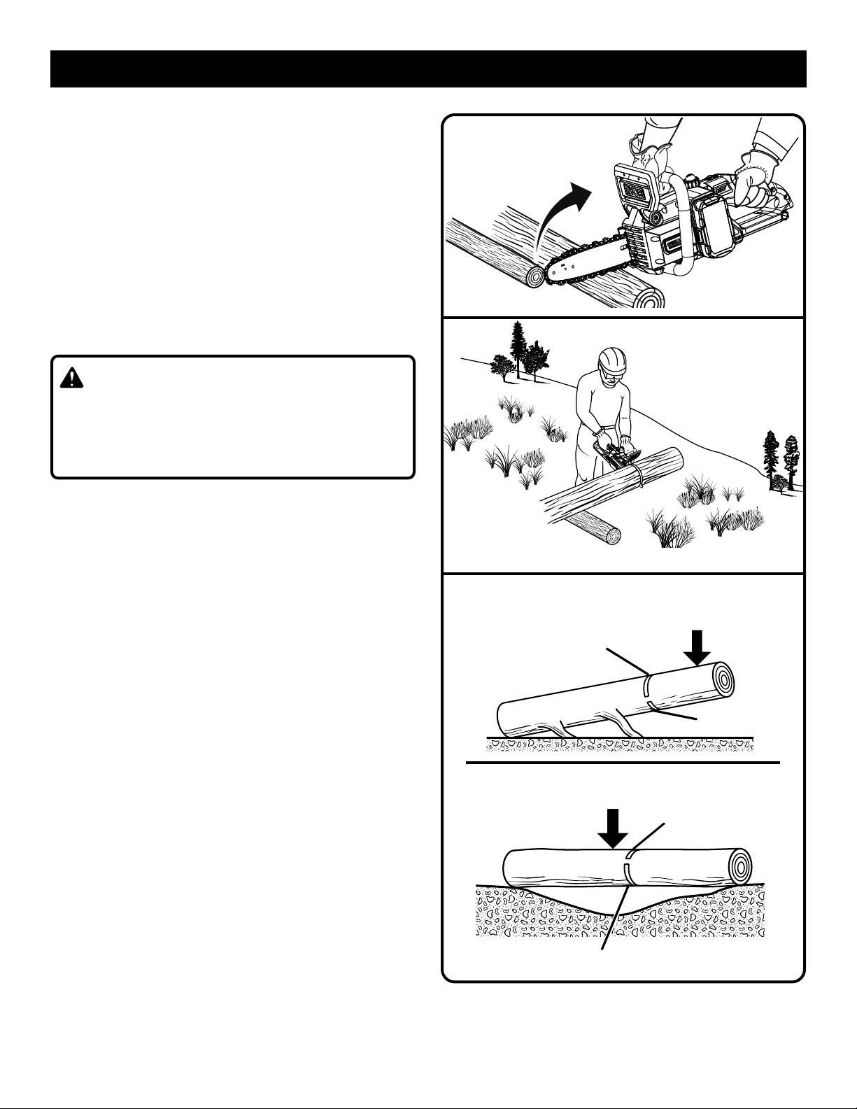
BUCKING
See Figures 16 - 19.
Bucking is the term used for cutting a fallen tree
to the desired log length.
Always make sure your footing is secure and
your weight is distributed evenly on both feet.
Cut only one log at a time.
Support small logs on a saw horse or another
log while bucking.
Keep a clear cutting area. Make sure that no
objects can contact the guide bar nose and
chain during cutting, this can cause kickback.
Refer to Kickback earlier in this manual.
When bucking on a slope, always stand on the
uphill side of the log. To maintain complete con-
trol of the chain saw when cutting through the
log, release the cutting pressure near the end of
the cut without relaxing your grip on the chain
saw handles. Do not let the chain contact the
ground. After completing the cut, wait for the
saw chain to stop before you move the chain
saw. Always stop the motor before moving from
tree to tree.
KICKBACK
Fig. 16
Fig. 17
LOAD
FINISHING CUT
1ST CUT
1/3 DIA
LOG SUPPORTED AT ONE END:
LOG SUPPORTED AT BOTH ENDS:
FINISHING CUT
1ST CUT 1/3 DIA
LOAD
Fig. 18
Loading ...
Loading ...
Loading ...