Loading ...
Loading ...
Loading ...
11Section 5 — Service
5. The gear oil level is correct if the gear oil is
approximately halfway up the side of the main
drive shaft.
6. If the gear oil level is low, add gear oil as
described next. If the gear oil level is okay,
securely replace the oil fill plug.
7. When adding gear oil, use Mobil 1® Synthetic
75W 140.
8. While checking frequently to avoid overfilling,
slowly add gear oil into the oil fill hole until it
reaches the halfway point on the drive shaft.
9. Securely replace the oil fill plug.
Off-Season Storage
When the tiller won’t be used for an extended
period, prepare it for storage as follows:
1. Clean the tiller and engine.
2. Do routine tiller lubrication and check for
loose parts and hardware.
3. Protect the engine and perform
recommended engine maintenance by
following the storage instructions found in the
Engine Operator’s Manual. Be sure to protect
the fuel lines, carburetor and fuel tank from
gum deposits by removing fuel or by treating
fuel with a fuel stabilizer (follow the engine
manufacturer’s recommendations).
4. Store the tiller in a clean, dry area.
5. Never store the tiller with fuel in the fuel
tank in an enclosed area where gas fumes
could reach an open flame or spark, or where
ignition sources are present (space heaters,
hot water heaters, furnaces, etc.).
Belt Replacement
If the drive belt or reverse drive belt needs to be
replaced, see your local authorized dealer or refer to the
Replacement Parts Section for ordering information.
Use only a factory-authorized belt as an “over- the-
counter” belt may not perform satisfactorily. The
procedure requires average mechanical ability and
commonly available tools.
NOTE: When reinstalling the belt cover, be
sure to engage the bail and hold it so that
the drive belt is tight before attempting to
reinstall the belt cover. This will enable the
belt to fall under the belt keeping mechanism
built into the belt cover. Failure to do so could
damage the belt and/or belt cover.
Tines
The bolo tines will wear with use and should be
inspected at the beginning of each tilling season
and after every 30 operating hours. The tines can be
replaced either individually or as a complete set. See
the Replacement Parts Section for tine identification
and part numbers.
Tine Inspection
With use, the tines will become shorter, narrower and
pointed. Badly worn tines will result in a loss of tilling
depth, and reduced effectiveness when chopping up
and turning under organic matter.
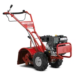
Refer to Figure 5-1 for the following tine procedures.
Front/Forward
Rear/Operator
Hex Screw
Flange Lock Nut
Hex Lock Nut
Hex Screw
Figure 5-1
Removing/Installing a Single Tine
1. With the engine shut off and the spark plug
wire disconnected, remove the two hex screws
(⁄-16 x 1.00) and hex lock nuts (⁄-16) that
attach a single tine to a tine holder. If needed,
use penetrating oil on the nuts.
2. When installing a single tine, be sure to
position it so that its cutting edge (sharp) will
enter the soil first as the tiller moves forward.
Removing/Installing a Tine Assembly:
1. A tine assembly consists of eight tines
mounted on a tine holder.
2. If removing both tine assemblies, mark them
“left” and “right” before removal. Remove the
hex screw (⁄-16 x 1.75) and flange lock nut
(⁄-16 ) that secure the tine assembly to the tine
shaft. If necessary, use a rubber mallet to tap
the tine assembly outward off the shaft.
3. Before reinstalling the tine assembly, inspect
the tine shaft for rust, rough spots or burrs.
Lightly file or sand, as needed. Apply a thin
coat of grease to the shaft.
4. Install each tine assembly so that the cutting
(sharp) edge of the tines will enter the soil first
when the tiller moves forward. Secure the tine
assembly to the tine shaft using the screw and
locknut.
Change Transmission Gear Oil
NOTE: The transmission gear oil does not need to be
changed unless it has been contaminated with dirt,
sand or metal particles.
1. Drain the gasoline from the fuel tank or run
the engine until the fuel tank is empty.
2. Drain the oil from the engine.
3. Remove the hex washer screw (⁄-20 x .500)
and flat washer (.28 x .74 x .500) from the left
side of the belt cover (if so equipped) and the
hex washer screw (⁄-20 x .500) from the right
side of the belt cover. Remove the belt cover.
See Figure 5-2.
Hex Washer Screw
Hex Washer Screw
Flat
Washer
Figure 5-2
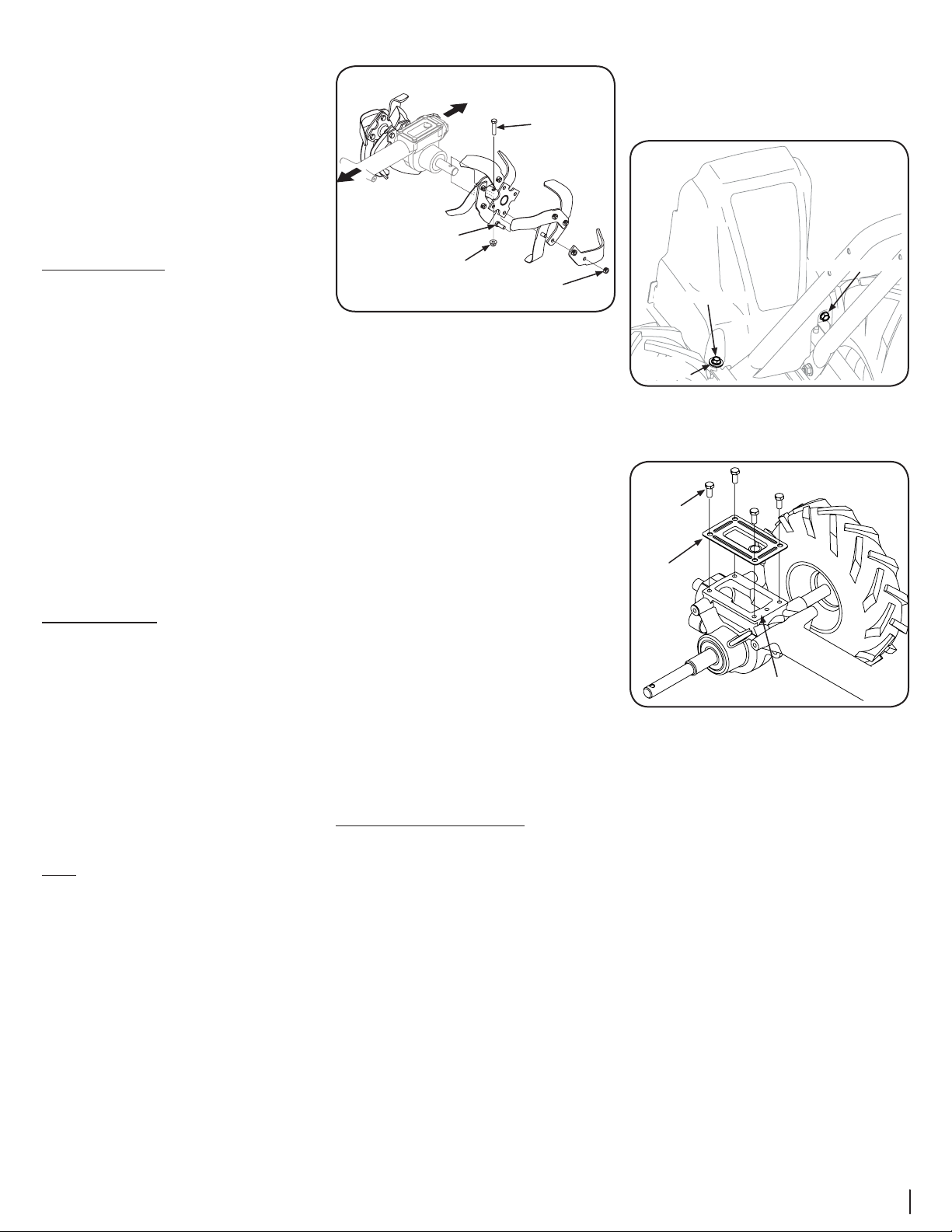
4. Remove all dirt and clean the area around the
transmission cover. See Figure 5-3.
Transmission
Housing
Transmission
Cover
Hex Screw
Figure 5-3
5. Remove the four hex screws (⁄-18 x .75)
securing the transmission cover to the drive shaft
and remove the cover. See Figure 5-3.
6. Remove the left-side wheel. Tilt the left-side
wheel shaft into a drain pan and allow the
gear oil to drain through the top of the
transmission.
7. Reinstall the wheel and reinstall the
transmission cover.
8. Refill the transmission using Mobil 1® Synthetic
75W 140. Refill the engine with motor oil and
replenish the fuel tank with gasoline.
9. Reinstall the belt cover.
Loading ...
Loading ...
Loading ...