Loading ...
Loading ...
Loading ...
Long press the 【TEST】 button to display/hide the 8 real-time measurement
parameters displayed in the upper part of the screen:
Vertical sensitivity.Indicates the voltage represented by one grid in the
vertical direction
1X/10X mode indicator icon.This must be consistent with the 1X/10X switch
setting on the probe handle.If the probe is in 1X gear, then the oscilloscope
should also be set to 1X gear.1X measures ±40V voltage, 10X measures
±400V voltage
Horizontal time base.Indicates the length of time represented by one grid in
the horizontal direction
Input coupling mode indicator icon.AC stands for AC coupling.DC stands for
direct current coupling
Run pause indicator.RUN means run.STOP means pause
7
8
9
10
11
Vmax = Maximum voltage
Vmin = Minimum voltage
Vave = Average Voltage
Vrms = RMS voltage
Vpp = Peak-to-Peak Voltage
Fre = Frequency
Dut = Positive duty cycle
Cyc = Cycle
【5.2】 Real-time Measurement Parameters
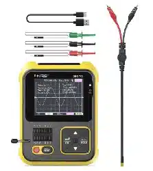
【5.3】 Oscilloscope Probe
NOTE!
Note: When the waveform amplitude exceeds the screen,these
measurements will produce large errors
PAGE
Insert the oscilloscope probe with the MCX plug into the top 【DSO】 jack.First
adjust the attenuation file on the probe.Clip the probe's ground to the
"reference ground" of the circuit under test
The probe tip or hook is securely connected to the node under test in the
circuit.Observe the voltage waveform of the measured point on the screen
1.The attenuation ratio of the probe should match the voltage of the
signal under test.Please do not measure voltage signals that exceed
the maximum range
2.When measuring the signal exceeding the safe voltage, the human
body should not touch the exposed metal part of the instrument to
avoid electric shock injury
Loading ...
Loading ...
Loading ...