Loading ...
Loading ...
Loading ...
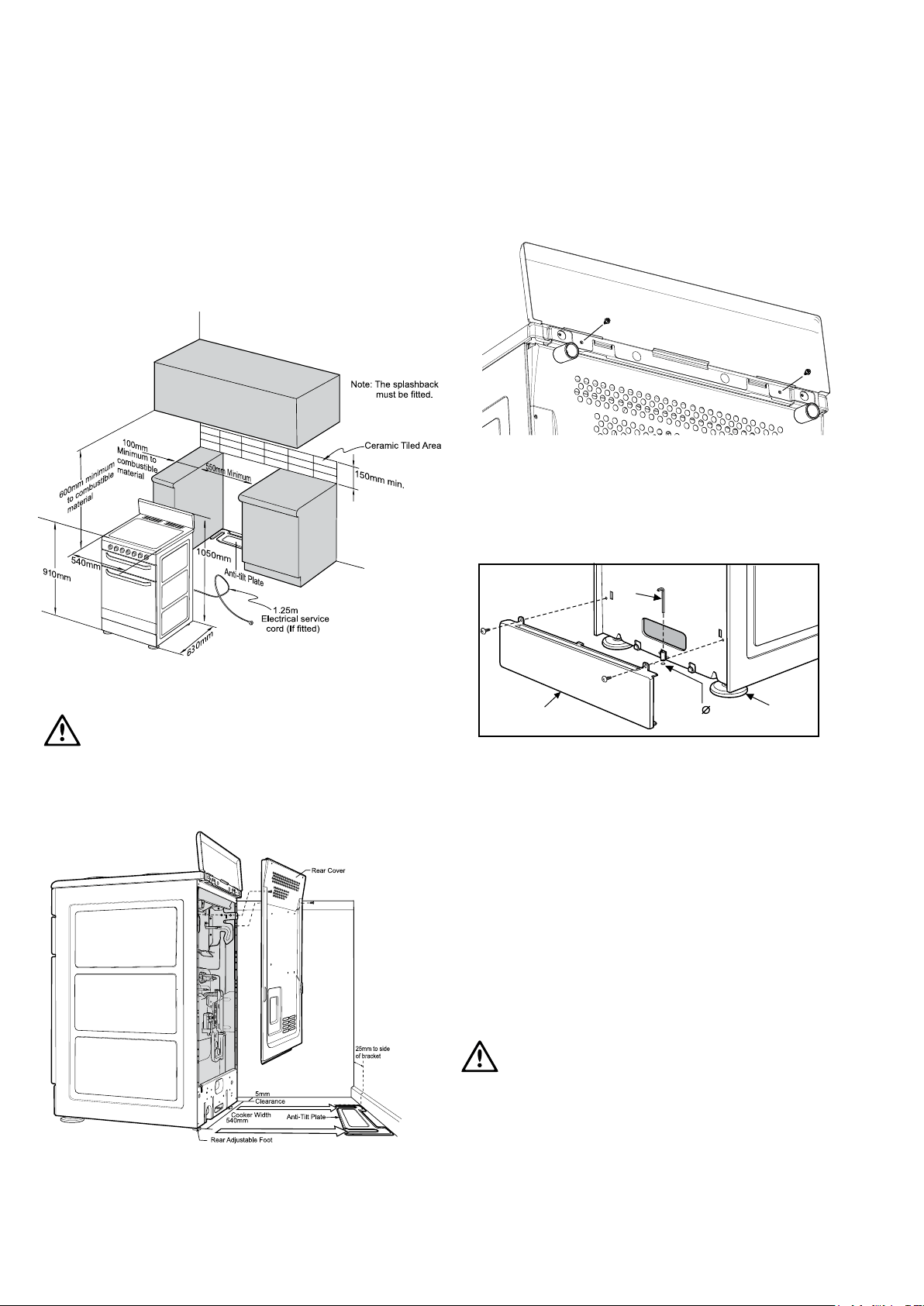
installation
Location
The appliance has been designed to fit in a 550mm wide gap
in kitchen cabinets or free space either side. Make sure the top of
the cooker is at least 10mm higher than the level of the bench top.
WARNING
warning
In order to avoid accidental tipping of the appliance (for
example, by a child climbing onto the open oven door), the
anti tilt plate and stabilising bolt MUST be installed.
Position anti-tilt plate to the rear wall and 25mm from side of
cupboard. Securely fix anti-tilt plate to the floor with fasteners.
Adjustlevellingfeetoncookerasrequired.
Chef 540 Upright Cooker INSTALLATION 17
Splash back must be fitted to the rear using two screws provided
Stabilising bolt
1. Removeovendoor-tobedonebyqualiedpersonnelonly.
(Refer to procedure).
2. Remove screws from kick panel. To remove kick panel lift
kick panel upwards to release the two Location Tabs from
the holes in the bottom of the panel
3. Position cooker into the ant-tilt plate and then mark the
position for the Stability Bolt hole on the floor
4. Pull cooker out and drill the bolt hole, using a 6.5mm
masonry or wood drill. Minimum 30mm deep for concrete
5. Reposition cooker back into place and fit the Stability
Bolt through the slot and into the drilled hole
6. If the cooker is placed on a base, measures must be
taken to prevent the appliance slipping from the base.
Front
Adjustable
Feet
Stability
Bolt
6.5mm
Drilled
Location Hole
Kick-panel
WARNING
For your safety this cooker is designed to be moved out of
positionbyaqualiedpersononly.
Loading ...
Loading ...
Loading ...