
Visit SSL at:
www.solidstatelogic.com
© Solid State Logic
All rights reserved under International and Pan-American Copyright Conventions
SSL
®
and Solid State Logic
®
are ® registered trademarks of Solid State Logic.
ORIGIN™, ORIGIN 16™, ORIGIN 32™, SuperAnalogue™, VHD™ and PureDrive™ are trademarks of Solid State Logic.
All other product names and trademarks are the property of their respective owners and are hereby acknowledged.
No part of this publication may be reproduced in any form or by any means, whether mechanical or electronic, without the
written permission of Solid State Logic, Oxford, OX5 1RU, England.
As research and development is a continual process, Solid State Logic reserves the right to change the features and
specications described herein without notice or obligation.
Solid State Logic cannot be held responsible for any loss or damage arising directly or indirectly from any error or omission in
this manual.
PLEASE READ ALL INSTRUCTIONS, PAY SPECIAL HEED TO SAFETY WARNINGS.
E&OE
October 2022
Revision History
Revision V1.0, January 2020 - Initial Release
Revision V1.1 - February 2020 - First Minor Revision Release
Revision V2.0 - October 2022 - Update to include 16 channel Origin
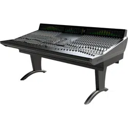
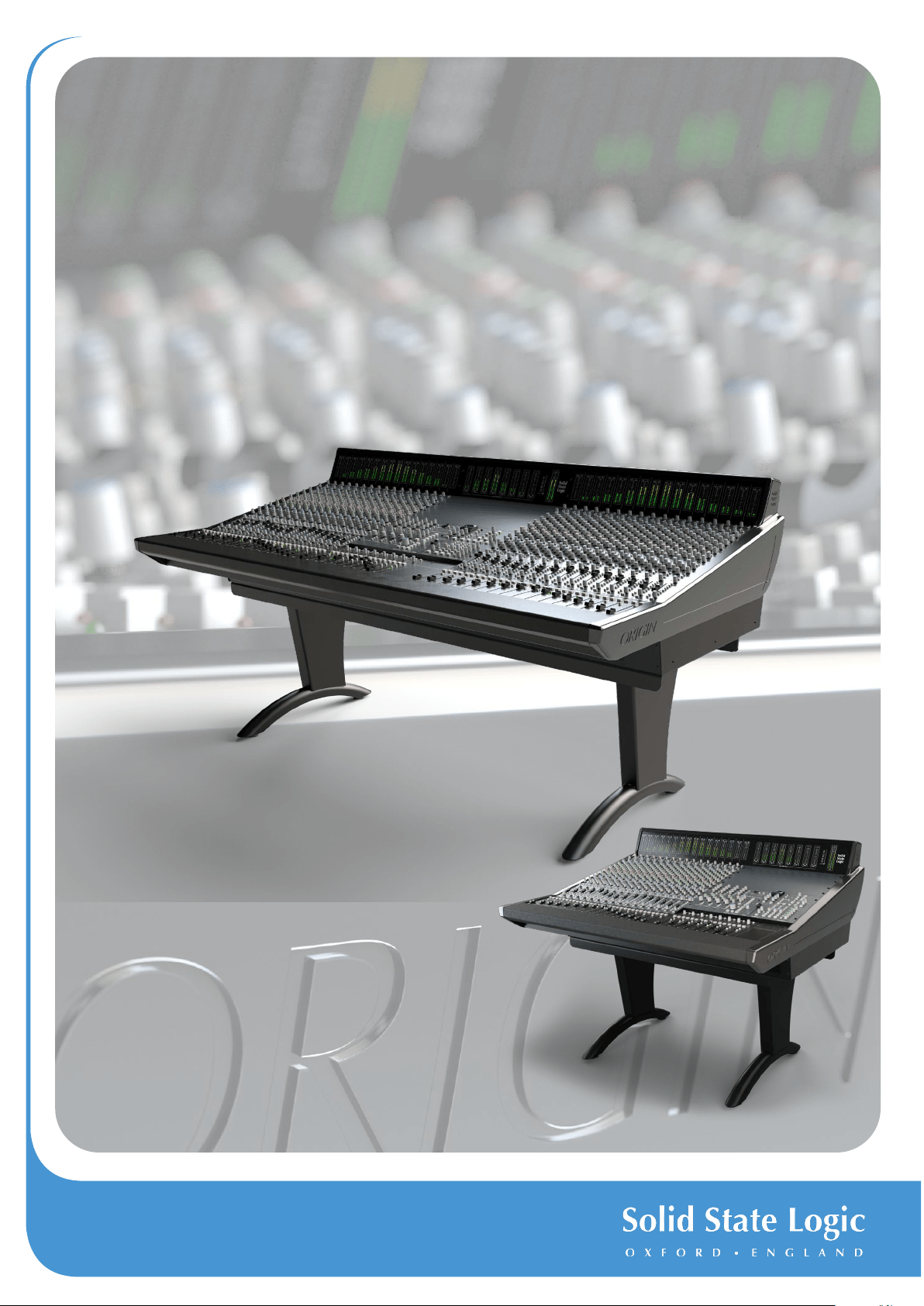
About ORIGIN
ORIGIN takes a fresh look at what a large format console needs to do to work in harmony with a modern DAW-driven production
studio. The functional design looks back at the ‘ORIGIN’ of in-line consoles for signal ow inspiration, but its circuits are at the
cutting edge of SSL’s latest analogue developments. These new analogue designs deliver huge dynamic range and bandwidth
yet still have the characterful, pleasing qualities of space and depth that analogue audio breathes on digital audio.
ORIGIN’s simple signal ow and layout make it easy to understand and use, while powerful features such as channel direct outputs,
a fully balanced electronic architecture and precision bargraph meters make it a perfect partner for the highest quality convertors
and DAWs in the most professional production applications.
A unique and innovative modular centre section allows ORIGIN to adapt to different applications and priorities, whether being used
as a purely tracking console with additional boutique analogue additions to the 19” rack centre section, or a very digital/analogue
hybrid approach with screens and controllers easily reached from the centre of the console.
ORIGIN offers engineers and producers the tools required for everything from large-scale tracking to hybrid mix down session.
Taking sustainability, ergonomics, modern gain-staging and communication requirements into consideration, ORIGIN offers a
reassuringly familiar Master Control feature-set with some ahead-of-the-curve functionality.

Contents
ORIGIN User Guide
Table of Contents
Introduction 1
Unpacking and Installation 2
Safety Notices 2
Dimensions 2
Origin 32 Channel Frame Widths 3
Origin 16 Channel Frame Widths 4
ORIGIN Channel Strip 5
Channel Strip Overview 5
Detailed Channel Description 6
SuperAnalogue PureDrive™ CHAN (Channel) Pre-Amp input 6
MON (Monitor) Input 7
Input Metering 8
Channel DIRECT OUT 8
Stereo Cue Sends 9
Mono Auxilliary (Aux) Sends 9
Parametric EQ and High Pass Filter (HPF) 10
ORIGIN 11
Path Block Diagram 11
ORIGIN EQ Curves 12
ORIGIN 13
Path Block Diagram 13
BUSES (LF or SF Path routing to Track Buses) 14
Small Fader (SF) Section 16
Small Fader (SF) 16
SF PAN 16
SF FROM LF 16
0dB 16
Small Fader Insert 16
Insert In (INS IN) and Insert Pre (INS PRE) 16
SF TO MIX 16
SOLO and CUT 16
Large Fader (LF) Section 17
Large Fader (LF) 17
LF PAN 17
Large Fader Insert 17
Insert In (INS IN) and Insert Pre (INS PRE) 17
LF TO MIX 17
0dB 17
SOLO and CUT 17
Stereo Groups 20
BUSES/STEREO GROUP METERS 21
MONO L and MONO R 21
BALANCE 21
0dB 21

Contents
ORIGIN User Guide
SOLO and CUT 21
ORIGIN Master Section 22
Overview 22
ORIGIN Master Section Detail 23
Stereo Returns 23
Bus Masters Trim and Routing 24
Monitoring 24
MIX BUS Fader 26
MIX BUS Insert 26
MIX BUS COMPRESSOR 26
MIX Bus Meter 27
COMMUNICATIONS 28
TALKBACK and LISTEN MIC 30
Talkback Microphone Connections (Mic and Line Inputs) 30
Listen Microphone Connections (Mic and Line Inputs) 31
CUES AND AUX MASTERS 31
AFL, PFL and the SOLO MASTER Section 32
SF SIP (Solo In Place), LF SIP, SUBGRP SIP and SOLO LINK 32
SOLO ACTIVE and SOLO CLEAR 32
PFL (Pre Fade Listen) 32
SOLO LEVEL 32
IN FRONT BALANCE 32
RED LIGHT 33
METERS Section 33
MIX METER FOLLOW MON SOURCE 33
PEAK MODE SELECT 33
PEAK CLEAR 33
DIM CHAN METERS and DIM BUS METERS 34
DIM MON METERS and DIM MIX METERS 34
OSCILLATOR 34
400 Hz ON and EXT IN 34
OSC LEVEL 34
TO MIX and TO BUSES 34
The MISC Section 34
SHIFT/ CLEAR ROUTE 34
Power Management Tools 35
Appendix A - ORIGIN Advanced Routing 36
Routing Terms 36
'From Channel' Routing - The typical approach for Analogue Consoles 36
Simple Channel to Bus Routing 36
Routing to Multiple Buses 36
Range Routing - more channels to more buses with less switch presses! 37
'To Bus' Routing - The other (more logical!) approach to routing 37
Simple Track Bus from Channel Routing 37
Routing from Multiple Channels 37
Range Routing 2 - more buses from more channels with less switch presses! 38

Contents
ORIGIN User Guide
Interrogating Routing - Finding Out What Is Routed Where? 38
Where Is This Channel Routed? 38
What Is Routed To This Track Bus? 38
Clearing Routes Quickly - the SHIFT switch 38
Clearing ALL Routes/Crosspoints Quickly 39
Routing LED Status Summary 39
Incremental Channel to Bus Routing 39
Latching/Momentary Key Function 39
Appendix B - Setup Functions 40
AUTO SLEEP Setup 40
ALT 3/Headphone Selection Setup 41
Automatic Incremental Routing Setup 41
Factory Setup Reset 42
To perform a Factory Reset: 42
Appendix C - Performance Specication 43
Audio Performance 43
PureDrive™ Channel Input Microphone/Line Amplier 43
Monitor Input Line Input Amplier 43
Channel Equaliser 44
Overall Channel Signal Chain Specications 44
Crosstalk 45
Overall Console Noise 45
Environmental Requirements 45
Appendix D - ORIGIN Block Diagram 46
Appendix E - Recall Sheets 47
Channel Recall Sheet 47
Master Section Recall Sheet 48
Stereo Group Recall Sheet 49
Appendix F - Suggested Patchbay Layouts 50
Origin 16 50
Origin 32 51

ORIGIN User Guide
Introduction
1
Introduction
Welcome to ORIGIN...
ORIGIN is a console that has traditional analogue ‘in-line’ studio workow at its heart and is the latest in a long heritage of large
format SSL studio mixing consoles. With the evolution of more sophisticated digital audio workstations and new hybrid approaches
to session workow, ORIGIN takes a fresh look at what an analogue console provides to complement these sophisticated tools to
make the production process fast, fun and creative.
While ORIGIN has a familiar surface, its design makes it adaptable for many different production scenarios. The 19” rack based
‘modular’ centre section allows the console to adapt to different control priorities and adds space for custom outboard processing.
For example, the addition of a 500 series rack provides a way to accommodate exible analogue processing from a number of
manufacturers, the ability to move the centre section allows for workstation controllers to be centrally located, even the 3U centre
meter panel can be moved to allow a workstation monitor to move closer to the engineer without obscuring the main meters.
SSL has invested thousands of hours of research into the sonic signatures of both analogue and digital processing in recent
years. This has resulted in new analogue designs that have found their rst showing in the acclaimed Fusion and SiX products
and which, along with a huge catalogue of proven and well-loved traditional SSL processing, have been brought together in the
design of ORIGIN.
A purely analogue design, ORIGIN represents a new benchmark in SSL’s SuperAnalogue™ performance with a unique sonic
signature while being unmistakably an SSL console;
- A new PureDrive™ mic pre inherits the clarity and purity of previous SSL Mic Pre designs that can also switch to a
warm, harmonically rich and driven tone that varies with mic pre gain when the “Drive” function is activated.
- A new mix bus and mix amp architecture delivers an amazingly low noise oor and huge headroom, along with SSL’s
latest summing bus technology that retains the classic SSL sound while bringing the breadth and space to mixes
that engineers and producers love from analogue.
- Acclaimed SSL E-Series four band parametric channel EQ.
- Classic SSL Bus Compressor with sidechain access and HP lter.
- Balanced Insert Point per Large Fader and Small Fader Channel paths.
- Dedicated Channel Direct Output make it easy to print mixes to the workstation for easy mix revisions.
- Modern circuit designs and unique power management tools deliver ultimate reliability and low running costs.
The in-line structure provides the twin paths needed for recording to and summing from a workstation with simple path routing
indication and fast push switch access to alter signal ow. The balanced insert point per fader path is perfect to insert an SSL
Sigma, adding level automation controlled directly from the DAW.
The console’s clear and simple signal ow make this an easy console to use. Simple path LED indicators show where processing
is in the signal chain, while a concise and clearly labelled master section is designed with all the tools needed to allow simple, fast
and creative session ow, plus the adaptable centre section provides great exibility for a focus on workstation control or more
pure analogue summing/recording applications.
ORIGIN brings a new SSL studio console within the reach of every large format production room budget and creates a great tool
for managing complex studio workow and maximising the efciency of modern workstation driven production processes.
Introduction
2
ORIGIN User Guide
Unpacking and Installation
This manual assumes that the ORIGIN console has been unpacked, assembled, wired to peripherals such as loudspeakers and
connected to a power source. Installation information can be found in the SSL ORIGIN Installation manual, which can be found in
the ORIGIN Documents section of the SSL Website (https://www.solidstatelogic.com/)
Safety Notices
IMPORTANT: Please read the safety notice information included in the Safety Guide supplied inside the box before using ORIGIN.
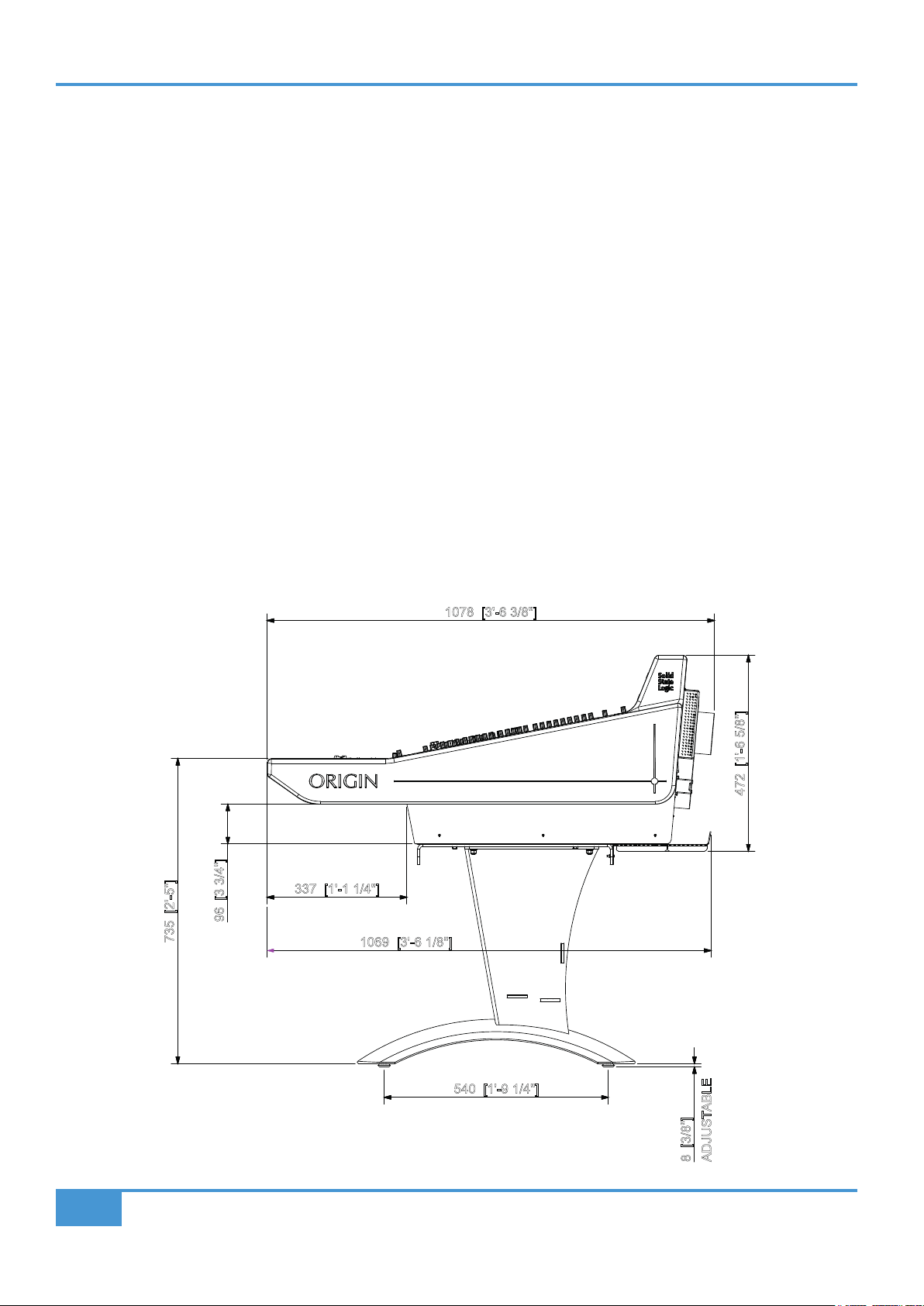
Dimensions
Approx. Dimensions in mm [and feet/inches] are shown in these diagrams.
Other specs are:
Approximate Weight:
330lb / 150kg including optional legs
Approximate Power Consumption:
Typically <900 Watts, 1200 Watts maximum when on
Typically <40 Watts when in standby/sleep.
540 [1'-9 1/4"]
735 [2'-5"]
1078 [3'-6 3/8"]
472 [1'-6 5/8"]
337 [1'-1 1/4"]
96 [3 3/4"]
8 [3/8"]
ADJUSTABLE
1069 [3'-6 1/8"]
ORIGIN User Guide
Introduction
3
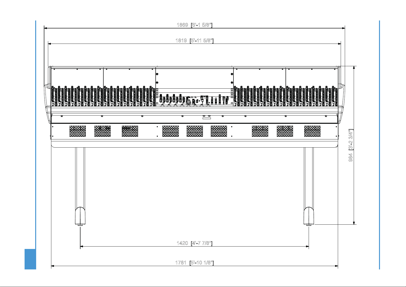
Origin 32 Channel Frame Widths
1420 [4'-7 7/8"]
1781 [5'-10 1/8"]
1869 [6'-1 5/8"]
1819 [5'-11 5/8"]
984 [3'-2 3/4"]
Introduction
4
ORIGIN User Guide
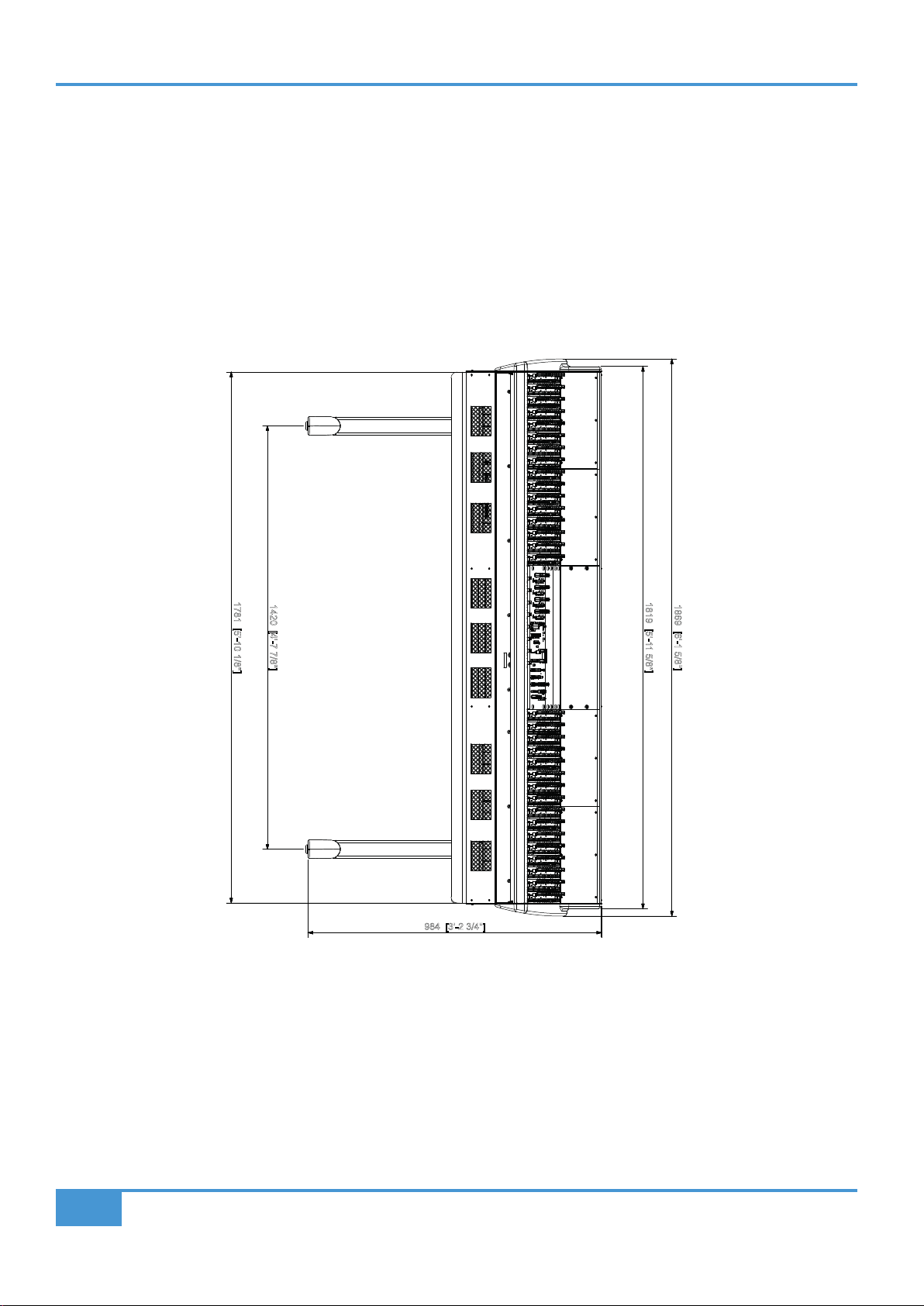
Origin 16 Channel Frame Widths
1420 [4'-7 7/8"]
1781 [5'-10 1/8"]
1869 [6'-1 5/8"]
1819 [5'-11 5/8"]
984 [3'-2 3/4"]

ORIGIN User Guide
Console Overview
5
ORIGIN Channel Strip
Channel Strip Overview
An overview of the ORIGIN Channel Strip features.
Section descriptions are in the following pages.
Channel Input typically feeds Small Fader Path for
recording, with versatile switchable Mic/Line pre-amp
featuring up to 70 dB of Gain, 48 V and Polarity Invert.
Drive provides a way to change the ultra clean linear pre-
amp to one with gentle warmth from harmonic distortion
and transient compression artefacts. Large Fader (LF)/
Small Fader (SF) Path indicator and ip switch allows use
of Drive circuit for Mixdown through Large Faders.
Line Level Monitor Input with Gain Trim, typically feeds
the Large Fader and is used with discrete DAW feeds
for analogue summing or record signal monitoring. The
Path Flip switch allows the Monitor Input to feed the
Small Fader.
Channel Direct Output provides the cleanest record path
to the recorder and frees track buses for more creative
use. It also provides a simple way to record post fader
paths to a DAW to 'print' Mix Stems.
The Pre Fader selection and LF/SF Path indicator/ip
switch allow for versatile path source selection.
Two Stereo Cue feeds (A and B), with Level Control and
Pan. Typically sent pre Large Fader to provide foldback
mixes that follow the control room Large Fader monitor
mix, the SF switch sources the feed from Small Fader
and Post Fader feed option allow use as additional
Stereo FX sends.
Four Mono Aux buses with Level control provides a
simple way to feed mixes to external effects or create
mono parallel mixes for additional bus needs. SF switch
to source Aux from Small Fader path and Pre Fader feed
option for creating mono foldback sends.
18 dB/oct High Pass Filter (HPF) sweeps from 10 Hz
to 400 Hz with IN switch and LF/SF Path indicator/ip
switch.
SSL E-Series ‘242’ EQ circuit
Four Band Parametric EQ with variable Cut/Boost per
band.
HF and LF bands have Bell switches to change from
shelving curves to bell curves for additional EQ sculpting.
HMF and LMF bands have separate Q controls to adjust
bell curve bandwidth in addition to gain and frequency.
IN switch for true circuit bypass.
LF/SF Path indicator/ip to switch path for the EQ.
Compact and sophisticated BUS/Channel Routing
ROUTE switch activates routing.
Blue LED indicates if channel routed to bus.
FOLLOW PATH PAN allows stereo odd/even bus
panning.
LF/SF Path indicator/ip switch.
OVERLOAD LED illuminates when Large or Small fader
paths within 3 dB of either path's clipping point monitored
pre Large and Small Fader, post processing.
Small Fader (SF) controls.
60mm high quality audio fader.
SF Pan with centre detent.
SF from LF sources feed from Large Fader.
0 dB switch bypasses fader to set unity gain.
INS IN switch SF Insert into Small Fader path.
INS PRE switches SF Insert pre fader.
SF TO MIX routes the Small Fader path to the MIX BUS.
SOLO and CUT for Small Fader path.
Large Fader (LF) controls.
100 mm high quality audio fader (not shown).
LF Pan with centre detent.
0 dB switch (not shown) bypasses fader to set unity gain.
INS IN switch LF Insert into Large Fader path.
INS PRE switches LF Insert pre fader.
LF TO MIX routes the Large Fader path to the MIX BUS.
SOLO and CUT for Large Fader path (not shown).
ORIGIN User Guide
Detailed Channel Description
6
Detailed Channel Description
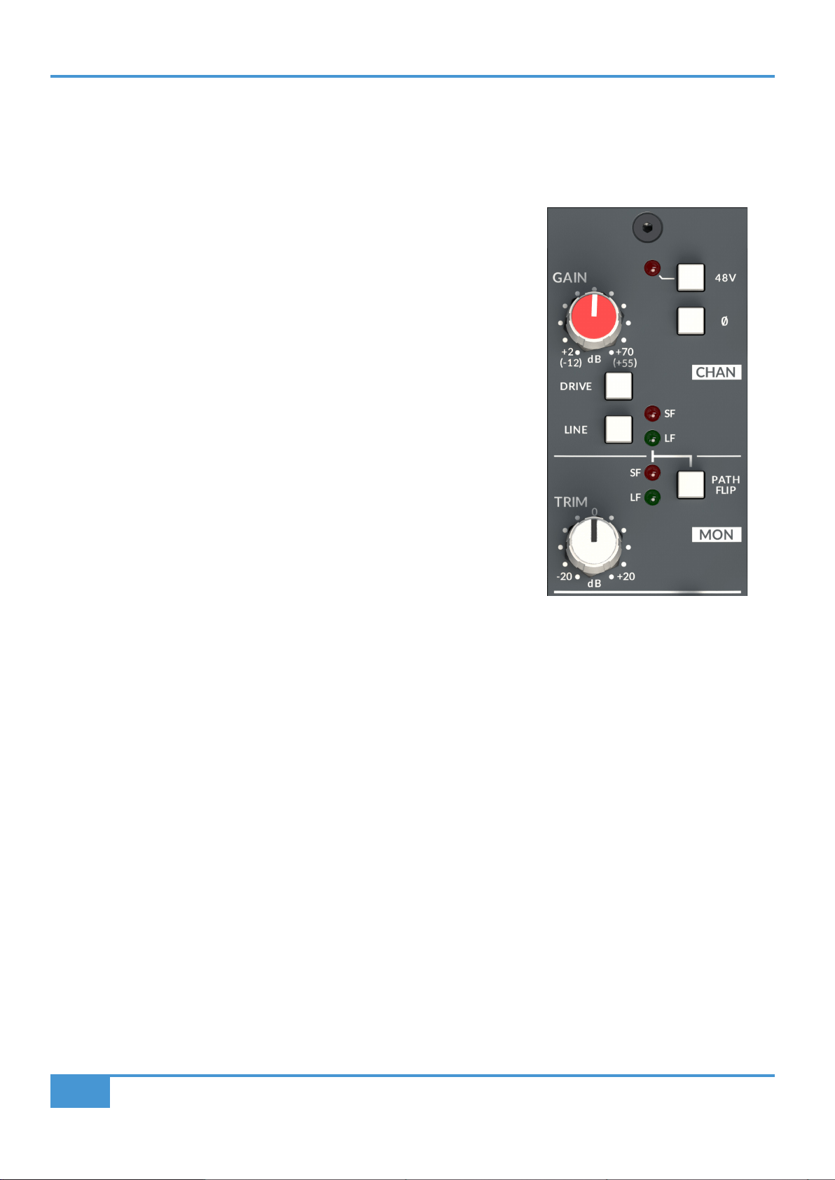
SuperAnalogue PureDrive™ CHAN (Channel) Pre-Amp input
ORIGIN’s pre-amp is a new wide gain range, ultra low noise SuperAnalogue design that provides both Line and Mic level
amplication by using a LINE gain range and input source switch to cover a wide range of source signals and levels.
The channel microphone input is via an XLR input on the rear of the console behind
the associated Channel strip. The line level channel input is via a DB-25 connector
also mounted on the rear of the console. Typically these inputs will be wired to a
Patchbay (see Appendix F). The XLR is the default source input, the source can be
switched to the DB-25 jack Line input by pressing the LINE switch on the channel.
The nominal Line Input impedance is 10 kΩ
The GAIN control adjusts either the microphone pre-amp gain (+2 dB to +70 dB),
or the Line amp gain (-12 dB to +55 dB), depending on the selected input source.
The Mic input’s nominal impedance is 1.5 kΩ and includes a ø polarity switch and
switched 48V phantom power.
DRIVE switch
The DRIVE switch signicantly changes the character of the pre-amp and how it
reacts to signal level. The default ORIGIN mic pre is a very clean, linear design which
has no distortion up to the clipping point of the channel strip (approx +27 dBu). With
the DRIVE switch pressed the pre-amp becomes reactive to signal level and gain
settings. As signal levels and gain settings increase there is an initial introduction
of 2nd harmonic distortion artefacts, then at higher signal levels/gain settings this
adds increasingly more 3rd harmonic distortion components up to the clipping point.
These effects also introduce some compression to transient signals.
The DRIVE feature is evolved from SSL's acclaimed VHD™ (Variable Harmonic Drive) circuits. These are found in a range of SSL
products from our 1U mic pre's to our largest production consoles.
ORIGIN User Guide
Detailed Channel Description
7
MON (Monitor) Input
The line level Monitor input is via a DB-25 connector (Mon Line In) also mounted on the rear of the console. Typically these inputs
will be wired to a patchbay (see Appendix F). Nominally this input is at unity gain, with a +20 db to -20 dB gain TRIM adjustment
to compensate for lower or higher Line level signals.
PATH FLIP
By default, the CHAN input feeds the Small Fader (SF) path and the MON input feeds the Large Fader (LF) path. This is indicated
by the red and green LEDs that bridge the line between these two sets of input controls. This default routing can be swapped by
using the PATH FLIP switch. When this switch is pressed, the red and green LEDs also ip status to show the path routing of the
input sections. This philosophy is repeated through the channel strip sections i.e.
RED LED : Small Fader Path
GREEN LED : Large Fader Path
Channel Input Block Diagram
GAIN
+48V
48V
MIC
+
-
MONITOR
LINE
+dB
TRIM
+2 to +70dB
[-12 to +55dB]
FLIP
PATH
10K
1.5K
LINE
-1
ø
DRIVE
-10dB
± 20dB
MONITOR
INPUT
CHANNEL
INPUT
LF
Large Fader Path
SF
Small Fader Path
MON
METER
CHAN
METER
ORIGIN User Guide
Detailed Channel Description
8
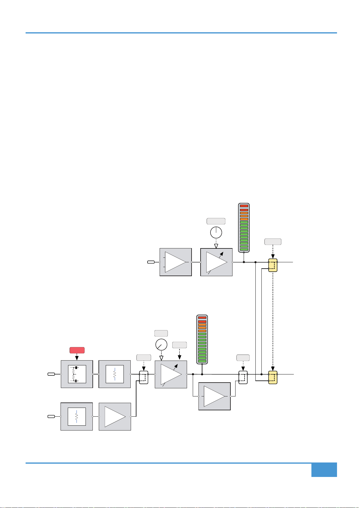
Input Metering
Above the channel are two high resolution 24 segment LED bargraph meters. These independently meter
the Channel and Monitor inputs for the channel below each respective meter and are calibrated in dBu
after the input gain stages.
Input Meters post input gain stages
The fast response peak meter has dened lines for
+24 dBu and +18 dBu as well as 0 dBu. The meter
has a fast ‘peak’ response and a slower release time
to meter peaks while still showing useful signal levels.
Origin's meters are accurately calibrated to a peak
reading of +24dBu, The metering of continuous signal
levels above +24dBu may show some slight differences
in decay rate from meter to meter arising from tolerance
variances in the meter's sample and hold circuits above
their calibrated peak level. This is normal behaviour for
these meters.
Channel DIRECT OUT
Each channel on ORIGIN has a fully balanced DIRECT
OUTput. This 'per channel' output provides a way to
send the selected path signal directly out of the channel
strip. This is normally post fader, but selectably pre-
fader using the PRE switch.
By default, the DIRECT OUTput is fed from the Small
Fader (SF) path as indicated by the red and green SF
and LF LEDs. This default routing can be swapped by
using the PATH FLIP switch.
The Channel Direct Out provides the cleanest record
path to the recorder and frees track buses for more
creative use. It also provides a simple way to print post
fader paths to a DAW to 'print' Mix Stems simplifying
mix revisions.
CHAN
IN
dBu
24
23
22
21
20
19
18
15
12
9
6
4
0
4
6
8
10
12
15
18
21
25
28
32
MON
IN
CHAN
IN
dBu
24
23
22
21
20
19
18
15
12
9
6
4
0
4
6
8
10
12
15
18
21
25
28
32
MON
IN
CHAN
IN
dBu
24
23
22
21
20
19
18
15
12
9
6
4
0
4
6
8
10
12
15
18
21
25
28
32
MON
IN
CHAN
IN
dBu
24
23
22
21
20
19
18
15
12
9
6
4
0
4
6
8
10
12
15
18
21
25
28
32
MON
IN
CHAN
IN
dBu
24
23
22
21
20
19
18
15
12
9
6
4
0
4
6
8
10
12
15
18
21
25
28
32
MON
IN
CHAN
IN
dBu
24
23
22
21
20
19
18
15
12
9
6
4
0
4
6
8
10
12
15
18
21
25
28
32
MON
IN
CHAN
IN
dBu
24
23
22
21
20
19
18
15
12
9
6
4
0
4
6
8
10
12
15
18
21
25
28
32
MON
IN
CHAN
IN
dBu
24
23
22
21
20
19
18
15
12
9
6
4
0
4
6
8
10
12
15
18
21
25
28
32
MON
IN
SF
FROM
LF
SOLO
MUTE
SOLO
MUTE
PRE FLIP
+
-
DIRECT OUT
PATH
to +10dB
Large Fader
Channel Path
0dB
0dB
MUTE
MUTE
to +10dB
Small Fader
Channel Path
GAIN
+48V
48V
MIC
+
-
MONITOR
LINE
+dB
TRIM
+2 to +70dB
[-12 to +55dB]
FLIP
PATH
10K
1.5K
LINE
-1
ø
DRIVE
-10dB
± 20dB
MONITOR
INPUT
CHANNEL
INPUT
LF
Large Fader Path
SF
Small Fader Path
MON
METER
CHAN
METER
ORIGIN User Guide
Detailed Channel Description
9
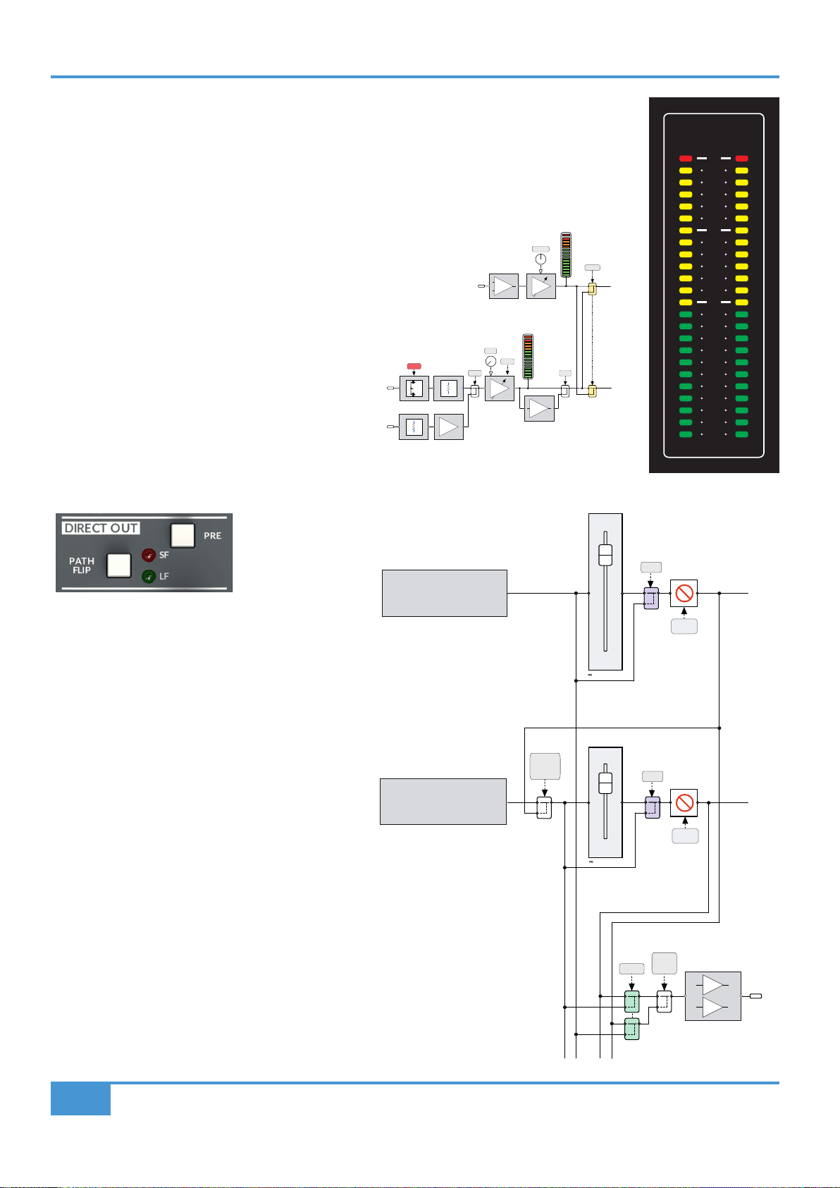
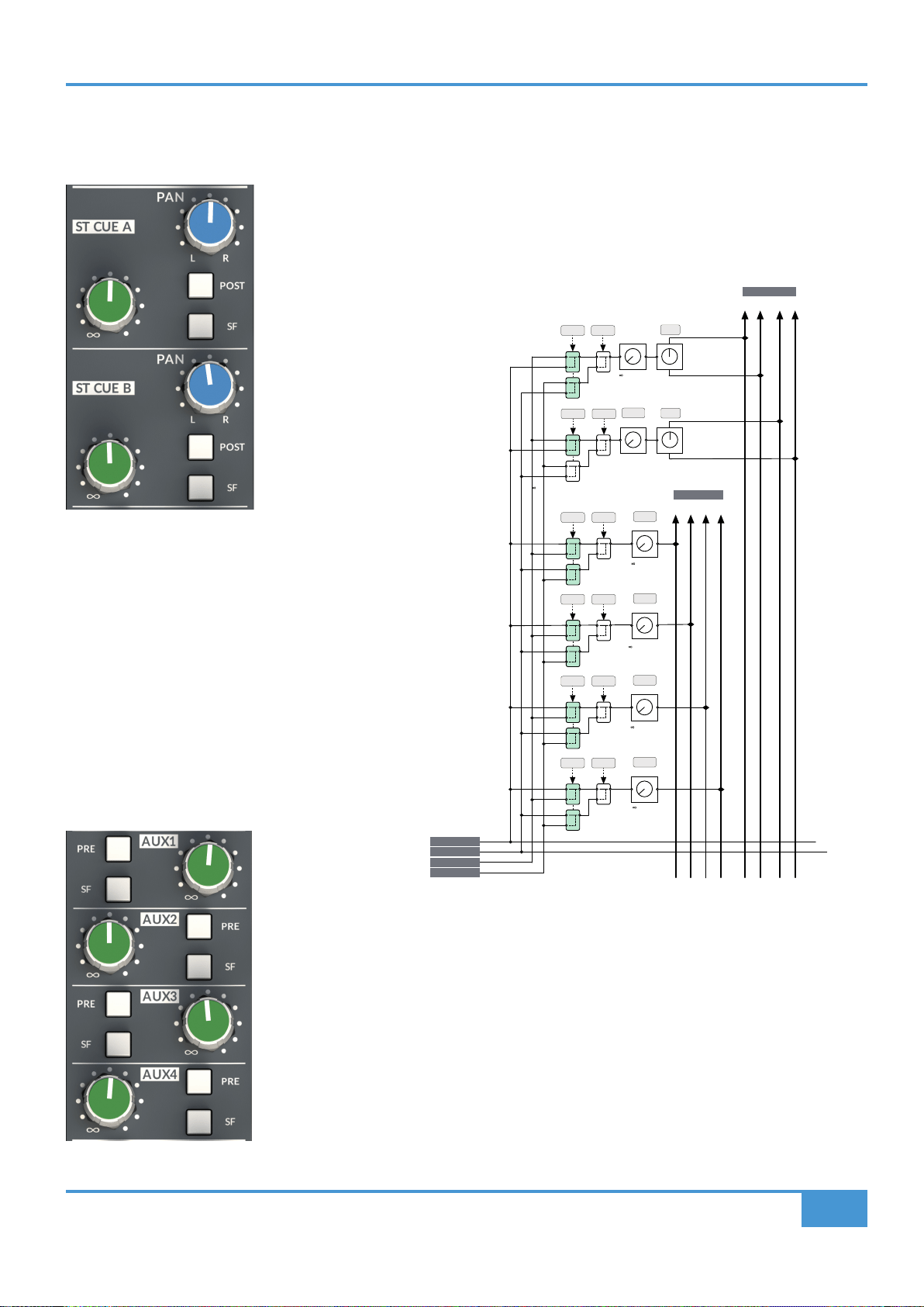
Stereo Cue Sends
Each channel can access two Stereo Cue sends (A and B) with independent Level and Pan controls.
By default, both sends are fed from the Large Fader path, pre-fader, post-insert, but can be
switched to Post Fader (post Insert) by engaging the corresponding POST switch. Each send can
also be switched to source their feed from the Small Fader path using the SF switch.
The channel signal is unity gain to the Cue Bus
when the Send Level control is fully clockwise
and the PAN control is hard left or right. The
centre Pan level is -4.5 dB from 0 dB to each bus:
a traditional SSL compromise between typical
mono -3 and -6 dB centre points for constant
perceived level or power.
Mono Auxilliary (Aux) Sends
Each channel can access four mono Aux sends
(1 to 4) with independent level controls.
By default, the Aux sends are fed from the Large Fader path, post-fader, post-insert, but can be
switched to Pre Fader (post Insert) by engaging the corresponding PRE switch. Each send can
also be switched to source their feed from the Small Fader path using the SF switch.
The channel signal is unity gain to the Cue Bus when the Send Level control is fully clockwise.
POST
SF
PAN
L R
L R
LEVEL
POST
SF
PAN
1 2 3 4
LEVEL
PRE
SF
LEVEL
PRE
SF
LEVEL
PRE
SF
LEVEL
PRE
SF
AUX 1 - 4
CUE A B
to 0dB
to 0dB
to 0dB
to 0dB
to 0dB
to 0dB
PRE LF PATH
POST LF PATH
PRE SF PATH
POST SF PATH
ORIGIN User Guide
Detailed Channel Description
10
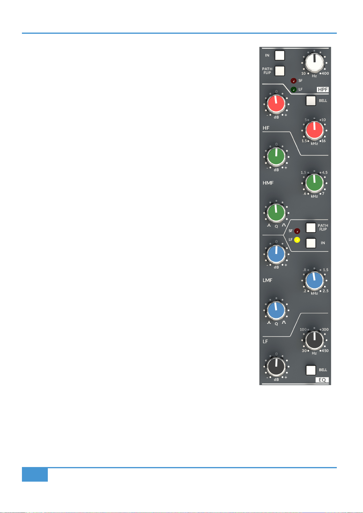
Parametric EQ and High Pass Filter (HPF)
At the top of the ORIGIN EQ section is the High Pass Filter (HPF) section. This has a 18 dB/
Octave slope and has a variable corner frequency from 10 Hz to 400 Hz. As can be seen in the
block diagram on the next page, the HPF actually follows the EQ section in the default signal
ow, however the HPF has an independant IN switch and also a PATH FLIP switch allowing it to
be separately positioned in the Small Fader (SF) or Large Fader (LF) paths.
The Parametric Equaliser in ORIGIN is based on the original SL4000E Series "242" equaliser
design i.e. SSL’s classic 'Black Knob' EQ.
The individual bands function as follows:
HF high frequency 12 dB/Octave shelving equaliser switchable to xed Q parametric (BELL).
HMF high frequency parametric mid band equaliser with continuously variable Q control.
LMF low frequency parametric mid band equaliser with continuously variable Q control.
LF low frequency 12 dB/Octave shelving equaliser switchable to xed Q parametric (BELL).
The EQ IN switch (located next to the insert switches) routes the channel signal through the EQ
section. The PATH FLIP switch allows the EQ to be separately positioned in the Small Fader (SF)
or Large Fader (LF) paths.
ORIGIN User Guide
Detailed Channel Description
11
+
-
+
-
PRE
IN
LF
INSERT
IN
FLIP
+
-
+
-
PRE
IN
FLIP
PATH
PATH
FLIP
PATH
IN
HPF
EQ
BELL
BELL
LF HF
Hz
to LARGE FADER
to SMALL FADER
from MONITOR INPUT
from CHANNEL INPUT
SF
INSERT
HPF
EQ
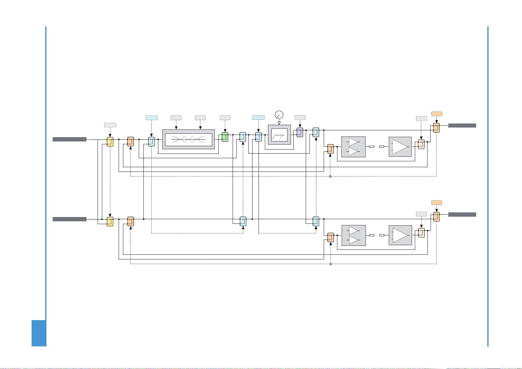
ORIGIN
Path Block Diagram

ORIGIN User Guide
Detailed Channel Description
12
HF Shelf HF Bell
HMF (Min and Max Q)
ORIGIN EQ Curves
LMF (Min and Max Q)
LF Shelf LF Bell
ORIGIN User Guide
Detailed Channel Description
13
+
-
+
-
PRE
IN
LF
INSERT
IN
FLIP
+
-
+
-
PRE
IN
FLIP
PATH
PATH
FLIP
PATH
IN
HPF
EQ
BELL
BELL
LF HF
Hz
to LARGE FADER
to SMALL FADER
from MONITOR INPUT
from CHANNEL INPUT
SF
INSERT
HPF
EQ
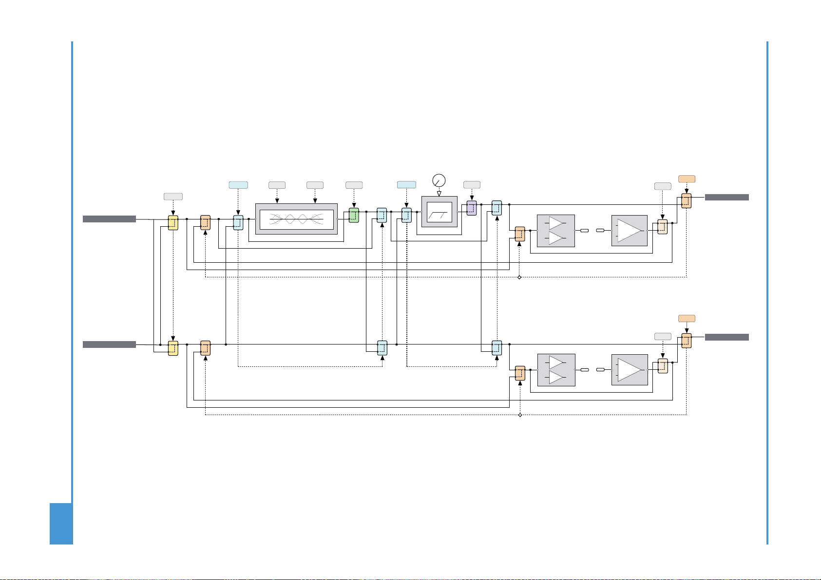
ORIGIN
Path Block Diagram
ORIGIN User Guide
Detailed Channel Description
14
BUSES (LF or SF Path routing to Track Buses)
ORIGIN is equipped with 16 buses, these buses are 'normally' connected in odd/even pairs to the 8 Stereo Group Buses. This
connection may be directly connected via DB25 connectors on the rear panel, or more typically, connected via half-normalled
connections on a patchbay for the console.
Typically on older analogue consoles, the track routing switches were located at the top of the channel strip. In ORIGIN we have
used some clever routing switching to minimise the amount of channel depth used for the routing feature while at the same time
adding a powerful and elegant way to route paths to buses.
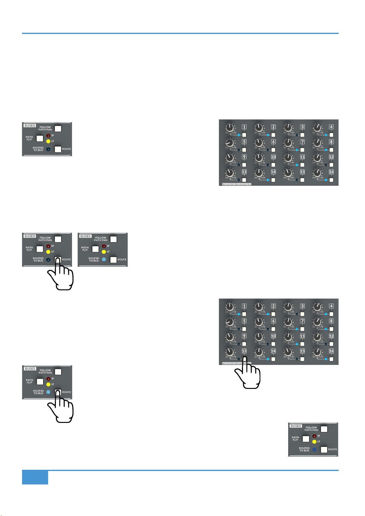
The key to routing to track buses with ORIGIN is using
the ROUTE switch in the BUSES section of the channel
strip (or a Stereo Return).
This works with the switches in the BUS TRIM MASTERS AND ROUTING
section in the centre section of the console.
In simple terms, there are two ways to route signals to track buses in ORIGIN:
Routing from a Path to a Bus (or Buses)
The rst, more traditional way, is to press the ROUTE switch in the BUSES section
on the channel strip you wish to route from.
The ROUTE LED in the channel will ash to show that it has been selected.
The switches in the BUS TRIM MASTERS AND ROUTING centre section panel
are now used to select which buses this channel strip will route to (e.g. 1 & 2).
When these switches are pressed the corresponding blue LED will brightly
illuminate to indicate that the selected path is currently routed to those buses.
Press the ashing channel strip ROUTE switch again
to deselect it from routing mode.
Exiting routing mode, the LEDs in the BUS TRIM MASTERS AND ROUTING section stay dimly illuminated
to show there is at least one path routed to the Bus. The same applies to the channel strip ROUTE LED,
which will also stay illuminated to indicate that the channel strip is routed to at least one bus.

ORIGIN User Guide
Detailed Channel Description
15
Routing to a Bus from a Path (or Paths)
The second way to route signals to Buses from Paths is to start with the Bus selection in the BUS TRIM MASTERS AND ROUTING
section in the Centre Section of ORIGIN.
Press the bus switch (adjacent to the Bus Trim control) in the BUS TRIM
MASTERS AND ROUTING section (e.g. Bus 1). This will ash the adjacent
blue LED to show that the Bus is selected.
Now use the ROUTE switch in the Path
(channel strip or FX return) that you wish
to route from.
This will cause the corresponding ROUTE LED to light bright blue.
You can select multiple Paths (e.g. channels 1,2,3,4,5,6,7,& 8) which will mean that channels 1 to 8 will be routed to Bus 1.
You can now press the selected bus switch again, or press the SHIFT/CLEAR ROUTE switch to escape routing mode.
Now any path or bus that has at least one path route will have its routing LED dimly lit.
Channel Strip Bus routing options
PATH FLIP : The default channel strip to Bus routing is from the Small Fader path (SF), indicated by the SF LED. The PATH FLIP
switch changes this to the Large Fader path (LF), indicated by the LF LED.
The bus routing is normally post fader, pre pan at unity gain. FOLLOW PATH PAN switches the Odd and Even Bus Routing to
follow the PAN of the selected path.
NOTE : For more advanced routing features see Appendix A (Advanced Routing)
ORIGIN User Guide
Detailed Channel Description
16
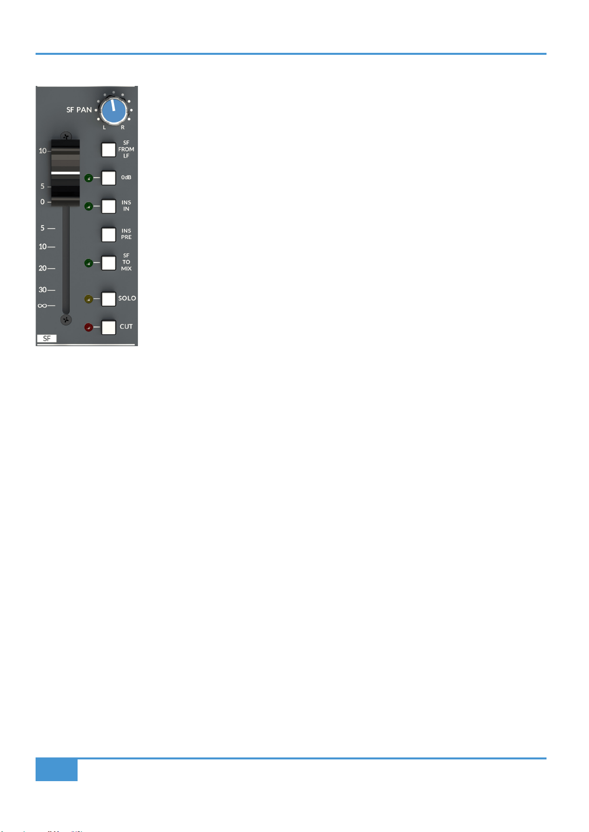
Small Fader (SF) Section
Small Fader (SF)
ORIGIN has two distinct signal paths in each channel strip. The Small Fader controls the signal level
in one of those paths (the SF path). ORIGIN's Small Fader is a 60 mm high quality audio fader, with a
fader law designed to provide more resolution around the 0 dB point, allowing subtle level changes
from modest fader movements. The fader output is unity gain to the bus when the Pan control is hard
left or right.
SF PAN
The Small Fader has a dedicated SF PAN control. As with other channel pan controls, the centre Pan
level is -4.5 dB from 0 dB to each bus - a traditional SSL compromise between typical mono -3 and -6
dB centre points for constant perceived level or power.
SF FROM LF
The Small Fader (SF) signal feed may be sourced from the Large Fader (LF) path (post fader) using
the SF FROM LF switch, This is useful when you want to use the Small Fader path to create a parallel
mix from the Large Fader path, routing via the buses to give a parallel mix with its own fader level/trim
control.
0dB
The 0dB switch bypasses the fader to give a xed unity gain through the Small Fader signal path. This is useful when levels are
set or automated within the DAW, thus allowing a session to be easily recalled by xing the console fader gain to unity.
Small Fader Insert
ORIGIN has a separate fully balanced Insert for both the Large Fader and Small Fader paths. The primary use of the insert is to
bring external processing into the signal path. For example, to insert a dynamics unit such as those found in SSL’s 500 series
modules. In conjunction with an automatable level control (e.g. SSL Sigma), they can also be a way to 'automate' the path level.
Insert In (INS IN) and Insert Pre (INS PRE)
In common with other SSL consoles, the Insert Send is always active, while the Insert Return switches into the signal path using
the INS IN switch. Typically the send is Post path processing, the INS PRE switch moves this point to Pre path processing. The
channel insert sends and returns are found on the rear panel 25 way D-Type connectors. Typically these are wired to a patchbay
for ease of use with other external devices. Wiring details are in the Connectors section, later in the document.
SF TO MIX
The SF TO MIX switch sends the Small Fader path to the main stereo Mix bus.
SOLO and CUT
The SOLO switch activates the Solo function for the Small Fader. The function of the SOLO switch is controlled by the SOLO
MASTER section in the centre section. Typically the SOLO switch is an After Fader Listen (AFL) function. This can be switched to
destructive Solo In Place using the SF SIP switch in the SOLO MASTER section. Additionally, the Small Fader Solo can be linked
to the Large Fader Solo and/or changed to be a Pre Fade Listen using the SOLO MASTER section PFL switch.
The CUT switch mutes the output of the Small Fader.
ORIGIN User Guide
Detailed Channel Description
17
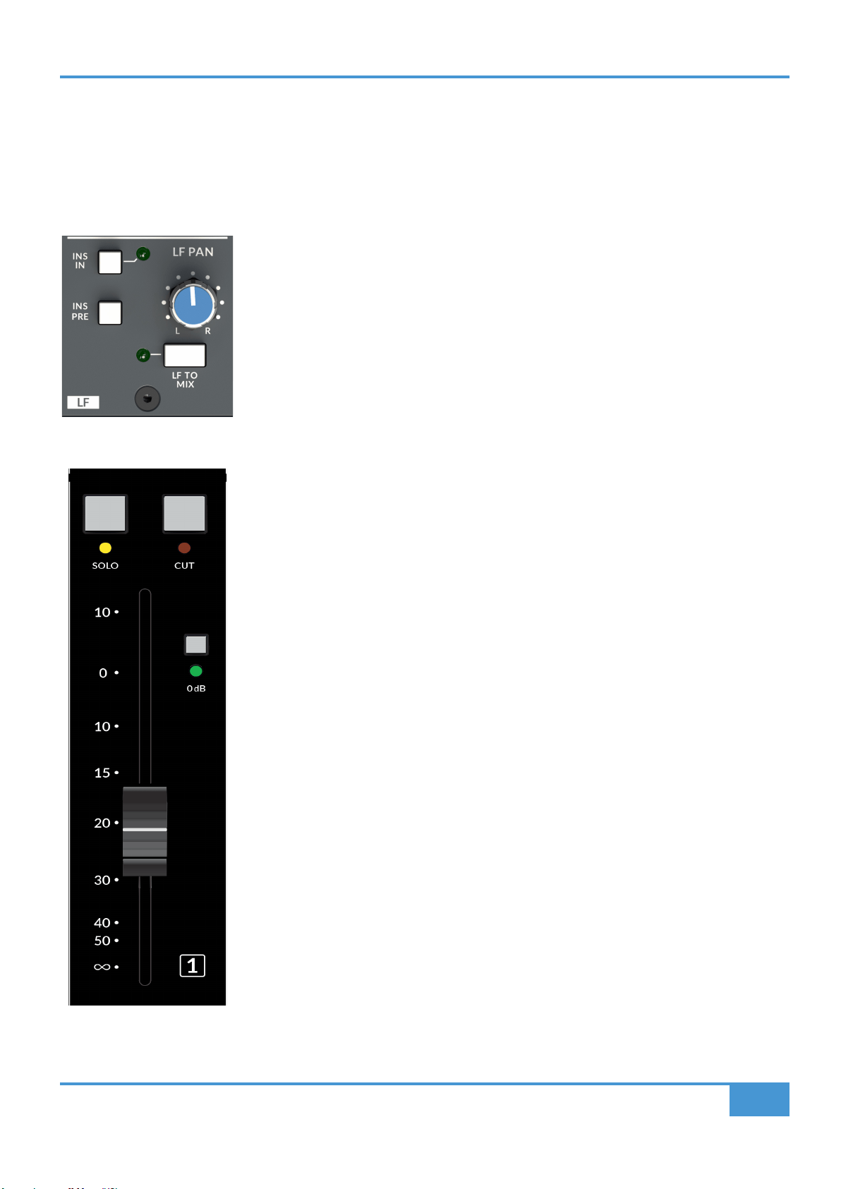
Large Fader (LF) Section
Large Fader (LF)
The Large Fader controls the signal level in the LF path. ORIGIN's Large Fader is a 100mm high quality audio fader, with a fader
law designed to provide more resolution around the 0 dB point, allowing subtle level changes from modest fader movements. The
fader output is unity gain to the bus when the Pan control is hard left or right.
LF PAN
The Large Fader has a dedicated LF PAN control. As with other channel pan controls, the centre
Pan level is -4.5 dB from 0 dB to each bus - a traditional SSL compromise between typical mono
-3 and -6 dB centre points for constant perceived level or power.
Large Fader Insert
ORIGIN has a separate fully balanced Insert for both the Large Fader and Small Fader paths.
The primary use of the insert is to bring external processing into the signal path. For example, to
insert a dynamics unit such as those found in SSL’s 500 series modules. In conjunction with an
automatable level control (e.g. SSL Sigma), they can also be a way to 'automate' the path level.
Insert In (INS IN) and Insert Pre (INS PRE)
Following the EQ and compressor in the channel signal ow is a fully balanced insert point.
In common with other SSL consoles, the Insert Send is always active, while the Insert Return
switches into the signal path using the INS IN switch. Typically the send is Post path processing,
the INS PRE switch moves this point to Pre path processing. The channel insert sends and returns
are found on the rear panel 25 way D-Type connectors. Typically these are wired to a patchbay
for ease of use with other external devices. Wiring details are in the Connectors section, later in
the document.
LF TO MIX
The LF TO MIX switch sends the Large Fader path to the main stereo Mix bus.
0dB
The 0dB switch bypasses the fader to give a xed unity gain through the Large Fader signal path.
This is useful when levels are set or automated within the DAW, thus allowing a session to be
easily recalled by xing the console fader gain to unity.
SOLO and CUT
The SOLO switch activates the Solo function for the Large Fader. The function of the SOLO switch
is controlled by the SOLO MASTER section in the centre section. Typically the SOLO switch is
an After Fader Listen (AFL) function. This can be switched to destructive Solo In Place using the
LF SIP switch in the SOLO MASTER section. Additionally, the Large Fader Solo can be linked to
the Small Fader Solo and/or changed to be a Pre Fade Listen using the SOLO MASTER section
PFL switch.
See the SOLO MASTER section on page 30 for more details on the Solo options.
The CUT switch mutes the output of the Large Fader.
ORIGIN User Guide
Detailed Channel Description
18
+
-
+
-
PRE
IN
LF
INSERT
IN
FLIP
+
-
+
-
PRE
IN
FLIP
PATH
PATH
FLIP
PATH
IN
HPF
EQ
BELL
BELL
LF HF
Hz
to LARGE FADER
to SMALL FADER
from MONITOR INPUT
from CHANNEL INPUT
SF
INSERT
HPF
EQ
Path Block Diagram

ORIGIN User Guide
Detailed Channel Description
19
Channel Section Notes
ORIGIN User Guide
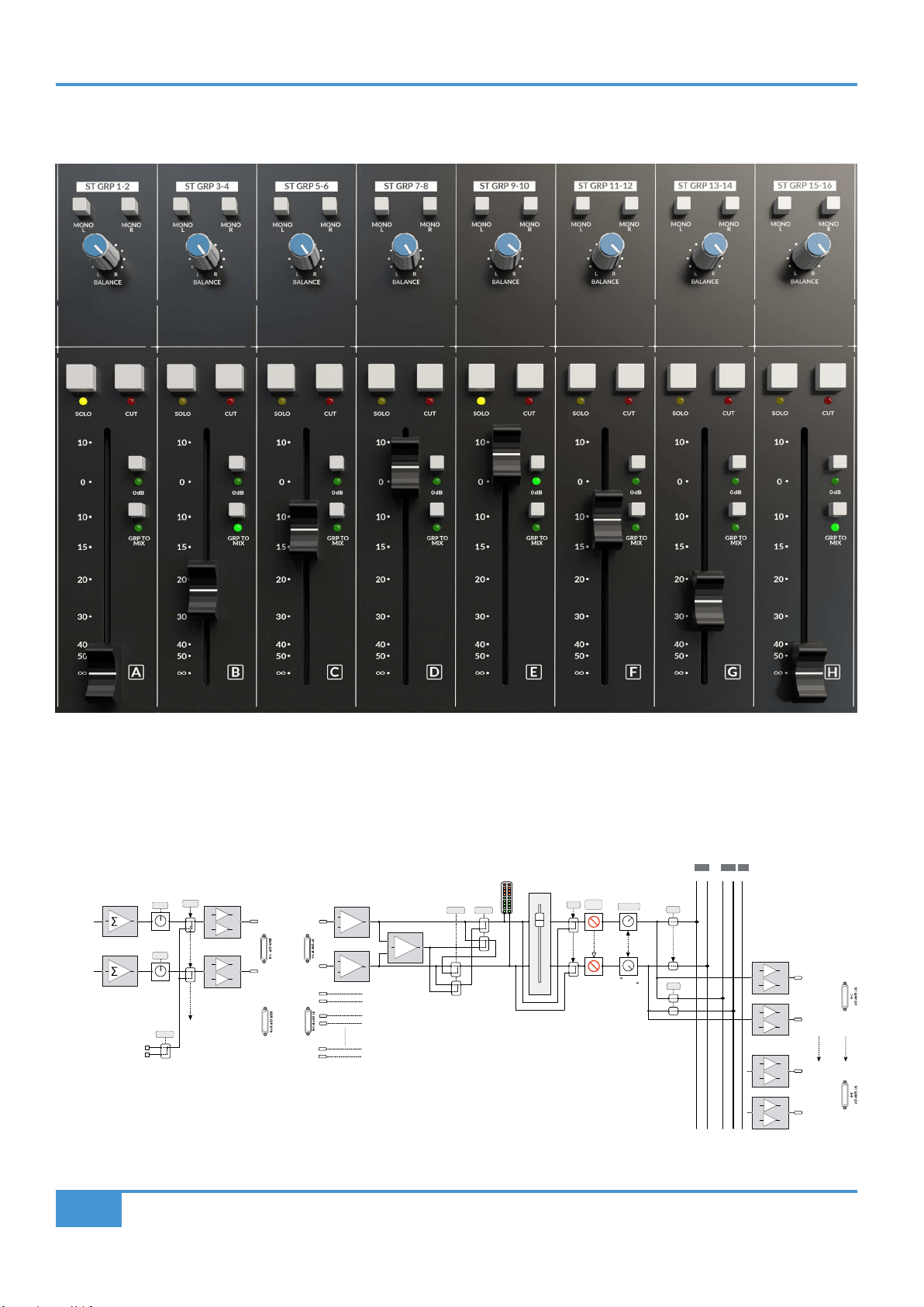
Origin Stereo Groups
20
Stereo Groups
Origin has eight Stereo Groups in the centre of the console. These are stereo 'audio' groups, i.e. they have audio passing through their faders,
as opposed to being VCA control groups. The inputs to these groups are via two DB-25 connectors on the rear of the console labelled ST GRP
IP 1-8 and ST GRP IP 9-16. This is because typically they are connected to the 16 console Track Buses, either directly via a DB-25 to DB-25 link
connector, or more typically via a patchbay. An overview of the Track Buses and Stereo Groups is shown in the block diagram below.
+
-
INPUT
+
-
+
MONO L MONO R
MUTE
BALANCE
to +3dB
+3dB to
MIX
SOLO
+
-
+
-
SUBGROUP
1L OUT
SUBGROUP
1R OUT
Stereo Groups
(A-H)
0dB
BUS SENDS CONNECT
TO STEREO GROUP IPs
VIA DB-25 LINK
OR HALF NORMALLED
PATCH ROW
+
-
+
-
SUBGROUP
8L OUT
SUBGROUP
8R OUT
L R
L R
L R
MIX AFL PFL
M
L R
MIX AFL
TRIM
BUS 1 SEND OUT
BUS 2 SEND OUT
OSC
SLATE
SLATE
TRIM
±20dB
±20dB
Track Buses
(1-16)
TONE
SLATE
TRACK BUS 1
TRACK BUS 2
+
-
+
-
ORIGIN User Guide
Origin Stereo Groups
21
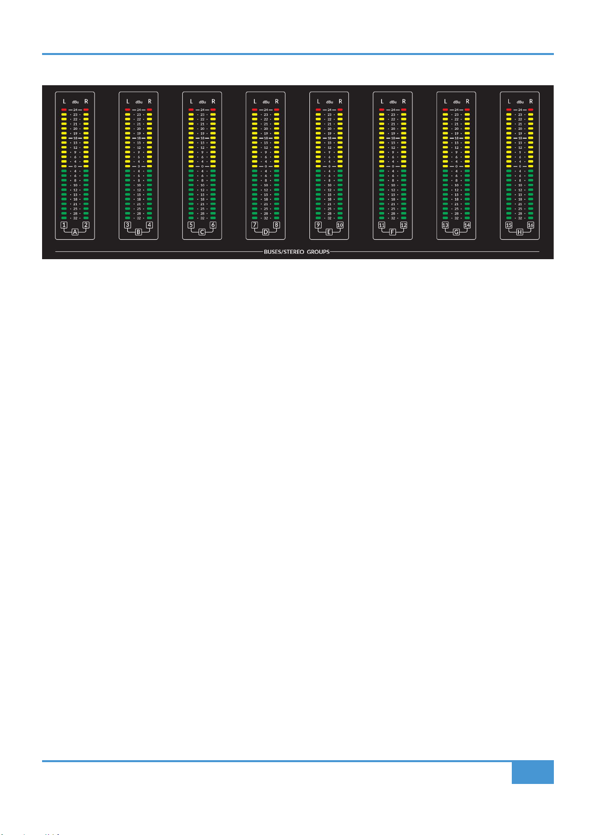
BUSES/STEREO GROUP METERS
Above the Centre Section are the eight stereo meters that show the levels coming into the Stereo Groups. As can be seen in the
block diagram on the previous page, the meters are fed after the input buffers and Mono switching, but before the Fader and
Balance controls. As the 'normal' wiring into the Stereo Groups is likely to be from the sixteen Track Buses, the meter labelling
shows this relationship with a combination of numbers with paired connections to the letters A-H representing the eight Stereo
Groups.
As with the channel metering, the meters are calibrated in dBu and they are peak meters with dened lines for +24 dBu and +18
dBu as well as 0 dBu. The meter has a fast ‘peak’ response and a slower release time to meter peaks while still showing useful
signal levels. (see note about high level signal metering on page 6 of this guide)
MONO L and MONO R
After the input buffers into the Stereo Groups there is Mono switching which allows a Mono signal to be split to both left and right
channels through the Stereo Group. The MONO L switch takes the left signal and sends it to left and right channels, the MONO R
switch takes the right signal and sends it to left and right channels. If both MONO L and MONO R switches are pressed, both left
and right paths are summed in mono through the Stereo Group.
BALANCE
The BALANCE control adjusts the balance of the left and right signals from the Stereo Group.
0dB
The 0dB switch bypasses the stereo group fader to give a xed unity gain through the Stereo Group signal path.
SOLO and CUT
The SOLO switch activates the Solo function for the Stereo Group Fader. The function of the SOLO switch is controlled by the
SOLO MASTER section in the centre section. Typically the SOLO switch is an After Fader Listen (AFL) function. This can be
switched to destructive Solo In Place using the SUBGROUP SIP switch in the SOLO MASTER section.
See the SOLO MASTER section on page 30 for more details on the Solo options.
ORIGIN User Guide
Origin Master Section
22
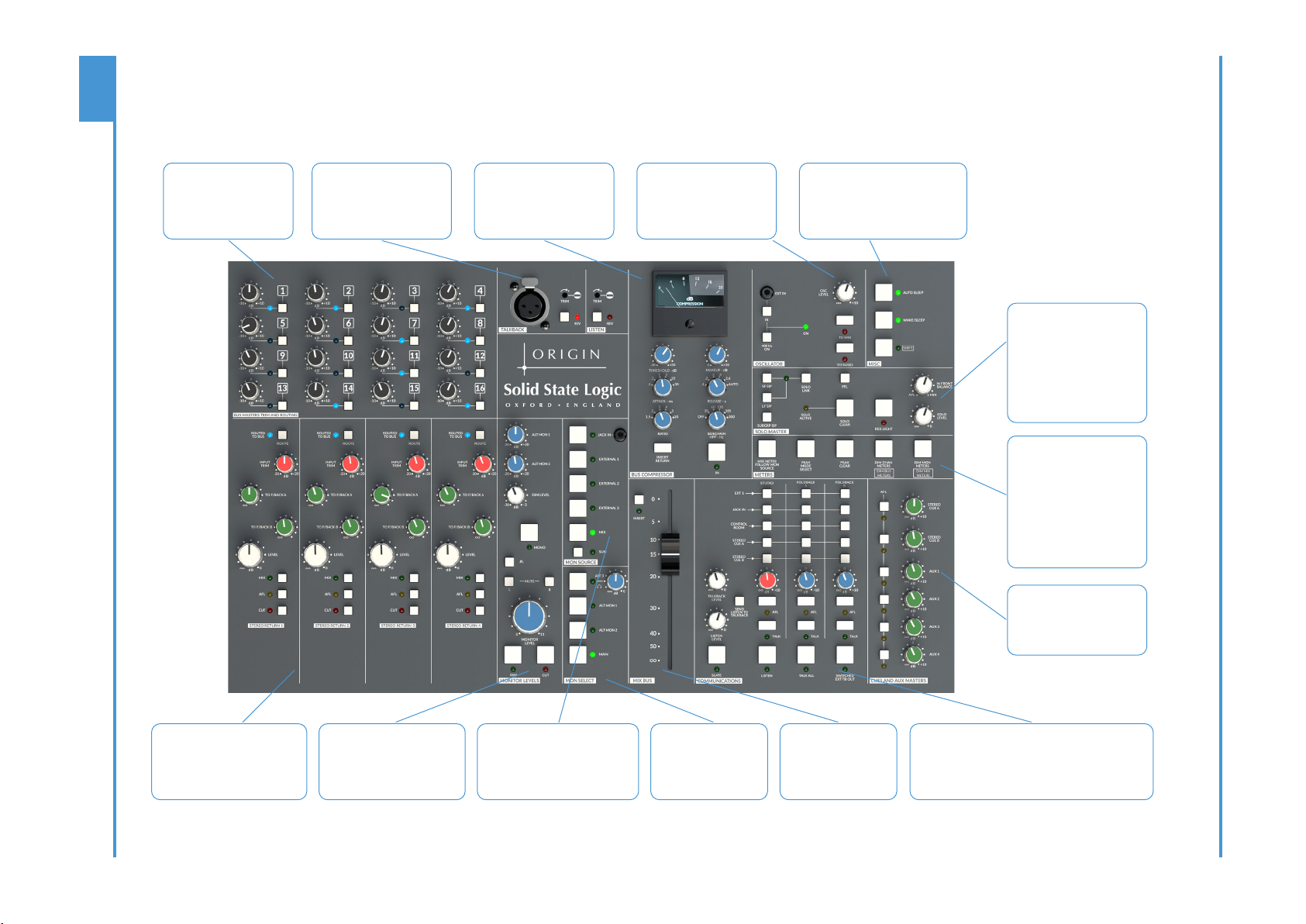
ORIGIN Master Section
Overview
Bus Trim Masters and
Routing
Sixteen +/-10 dB Trims for
the track buses
Routing assign switches for
each bus
Talkback and Listen Mic
XLR input for Talkback Mic
Level Trims and +48V
switches for Talkback and
rear panel Listen Mic Input
Bus Compressor
SSL Bus Compressor with
traditional and additional
Ratio settings, switchable
Sidechain High Pass Filter
and Sidechain from Insert
Return Switch
Oscillator
400 Hz Internal Oscillator with
additional switched 3.5mm
Jack external input. Level
Trim plus To Mix and To Bus
switches
Misc Section
Unique Auto Sleep function enables
automatic detection of prolonged
inactivity to put the console in
stand-by, drastically reducing
power consumption. Wake/Sleep for
manual control of the power state.
Solo Master Section
Comprehensive Solo controls
provide choice of Solo In
Front with Mix Balance, Solo
In Place for Large, Small
& Group Faders and PFL
options.
Solo Level, Solo Clear and
Red Light Switch complete
the available options.
Meters Section
Peak Hold selection plus
Peak Clear for all console LED
Meters.
Mix Meter Follow Monitor
Source option increases
main mix meter exibility.
Independent DIM controls
for path Channel and
Monitor Inputs reduce meter
distractions in busy sessions
CUE and AUX Masters
Master Output Trims and AFL
Switches for Stereo Cue A
and B buses plus mono Aux
Buses 1 to 4
Stereo Returns
Stereo Return Inputs with ability to
route to Mix and Track Buses plus
level controlled Feeds to Stereo
Foldback Outputs A & B
Monitor Level Controls
With independent Trims for
Alternate Monitors 1 & 2,
variable DIM level, MONO plus
Left & Right MUTES and øL
polarity switch.
Monitor Source Selector
Three Stereo External Sources plus
a front panel stereo 3.5mm Jack
Input. Sum switch allows selected
monitor sources to be listened to
simultaneously.
Monitor Speaker
Selector
Main Monitor plus two
Alternate monitor sets
plus headphones with
level control (under
console armrest)
Communications Section
Master Talkback and Listen controls. Matrix of sources
and outputs manage communications and foldback
to studio oor and artists. Listen To Talkback feature
provides a simple way for artist to artist communication
in larger recording rooms.
Mix Fader
High Quality 100 mm
Audio Fader
Fully balanced switched
Insert for external bus
processing

ORIGIN User Guide
Origin Master Section
23
ORIGIN Master Section Detail
Stereo Returns
ORIGIN has four Stereo Returns for external stereo sources such as external effects or additional stereo
submixes.
ROUTE
The Stereo Groups are able to be routed to the Track Buses in pairs and the routing works in an identical
way to the Channel routing (for more details see page 12 or Appendix A). The ROUTED TO BUS LED
illuminates at half brightness when the return is routed to any of the sixteen buses.
TO F/BACK A
Feeds the Stereo Return signal to Foldback A. Typically this is used to add an external effect (such as
reverb) to an artists headphone feed.
TO F/BACK B
In the same way as the previous control, this feeds the Stereo Return signal to Foldback B.
LEVEL
Controls the amount of the Stereo Return to the main stereo Mix Bus (or AFL)
MIX - Routes the Stereo Return to the main stereo Mix Bus
AFL - Routes the Stereo Return to the After Fade Listen (AFL) bus (and forces the monitoring to AFL)
CUT - Mutes the Stereo Return signal to the main Stereo Mix Bus
+
-
RETURN L
± 20dB
dB
TRIM
+
-
RETURN R
dB
L R
L R
LEVEL
LEVEL
LEVEL
MIX
AFL
1 2 3 4 5 6 7 8 9 10 11 12 13 14 15 16
1/2
3/4
5/6
7/8
9/10
11/12
13/14
15/16
CUT
FB 1
FB 2
L R
L R
to 0dB
to 0dB
to 0dB
BUSES 1 - 16
L R
MIX AFL
to 0dB
Stereo Return
F/B 1
F/B 2

ORIGIN User Guide
Origin Master Section
24
Bus Masters Trim and Routing
ORIGIN has sixteen track buses. These are
normally connected to the eight Stereo Group
buses (see page 18). This connection is either
directly via a DB-25 to DB-25 connection on
the rear of the console, or more typically via
normalled jack connections on a patchbay.
Bus Trim Controls
Upper left in the 6U Master Section, these 16
knobs are the individual +/- 10dB level trims
for the individual buses.
Route Switches and LEDs
Next to each of the Bus Trim controls is a Route
switch and LED. These switches and LEDs interact with the intelligent console bus routing system to both show and assign the
channels (and Stereo Returns) to the Buses. As described on page 12 and in Appendix A, these switches can be used to assign
or de-assign signals to the track buses. When the LEDs are illuminated with a solid (non-ashing) light this indicates something is
routed to that Bus. If the LED is not illuminated then there are no signals routed. If the LEDs are ashing, this indicates the section
is in 'Assign' mode and therefore using the Route switches will enable or disable signals. A more thorough explanation of ORIGIN's
powerful routing options can be found in the ROUTING section in Appendix A.
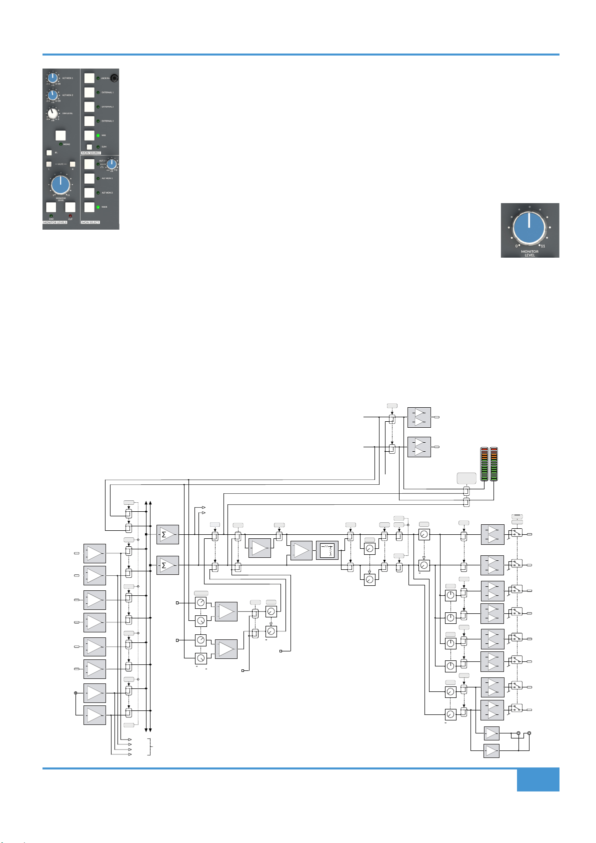
Monitoring
ORIGIN has a comprehensive control room monitor control and switching system. It supports up to three independent sets of stereo
monitors plus a headphone output. The section is split into three sub-sections covering monitor source, switching, level control and
audio image. In addition, there is a 'Studio' loudspeaker provision for a set of artist monitors located in the recording area, these
are described in the Communications section on page 26.
MON SOURCE
A choice of ve monitor sources are available with the default source being the internal MIX Bus.
This may be overridden by an intercancelling choice of three external sources (EXTERNAL 1, 2
& 3) plus an additional source from the front panel 3.5mm JACK IN Socket for sources such as
a tablet or mobile phone. External 1, 2 and 3 inputs are connected via a DB-25 connector on the
rear panel, these connections are also likely to be connected via an external patchbay.
An LED adjacent to the source switch shows current selection. There is also a source SUM feature
which allows a combination of any or all monitor sources to be listened to at the same time.
MON SELECT including headphones.
Three sets of control room monitors may be connected and selected from the MONitor SELECT
section. The available choices are MAIN, ALT MON 1 and ALT MON 2 and these are chosen with
the switch next to the label. An LED also indicates which monitor outputs are selected. All of the
monitor outputs are identical fully balanced outputs.
In addition to the Main and Alternate monitor outputs, there is also a pair of paralleled 1/4" Stereo
Headphone sockets located under the front armrest at the centre of the console. The output to
these is selected and the level controlled by the ALT 3/switch and shown by the adjacent
ORIGIN User Guide
Origin Master Section
25
LED. The headphone selection can be set up to intercancel with the other monitor selection switches (see
Appendix B - Setup Functions), however the level control is independent of the large MONITOR LEVEL
control in the MONITOR LEVELS section, but the output does follow the monitor CUT switch.
ALT3 output is also paralleled to a DB-25 connector on the rear of the console. It is therefore available as an
additional monitor output with independent level control (same pot as the headphone level).
MONITOR LEVELS
This section contains the main MONITOR LEVEL control plus additional level, mute and polarity switching.
The large MONITOR LEVEL pot is a precision audio taper pot that is calibrated from 0 to
11 (rst featured on an SL 4000 G-Series console supplied to Rhino Studios, Sydney in the
1980's and inspired by mythical guitarist Nigel Tufnel's custom ampliers). This level control
is the master level control for the MAIN, ALT MON 1 and ALT MON 2 monitor selections. Underneath the control
are switches for CUT and DIM. The CUT mutes the monitor outputs, the DIM control reduces the output of the
monitor output by an amount between -3dB and -30dB as determined by the DIM LEVEL control higher up in this section.
Above the large level control are MUTE L and MUTE R switches to independently cut the output of the left and right monitors
respectively. A large MONO switch mono's the L and R output to the monitors and reduces the level by 3dB to give a perceived
equal loudness when this is selected. The remaining controls in this section are trim levels for ALT MON 1 and ALT MON 2. These
allow additional monitors to trimmed to match the level of the main monitors to allow useful comparisons of a mix on the different
monitor sets.
+
-
+
-
MIX L OUT
MIX R OUT
+
-
MAIN L OUT
+
-
MAIN R OUT
ALT 1
+
-
ALT 1L OUT
+
-
ALT 1R OUT
ALT 2
+
-
ALT 2L OUT
+
-
ALT 2R OUT
ALT 3
+
-
ALT 3L OUT
+
-
ALT 3R OUT
MAIN
CUT L
CUT R
-1
POL
3dB
MONO
+
LISTEN
POWER
CUT
P/AFL
LISTEN
iJACK
+
-
L R
+
-
+
-
+
-
+
-
EXT 1
+
-
EXT 1L
EXT 1R
EXT 4
EXT 2
EXT 3
EXT 2L
EXT 2R
EXT 3L
EXT 3R
to 0dB
LEVEL
CUT
DIM
+dB
+dB
MIX
SUM
PFL
PFL
0 to -40dB
LEVEL
to 0dB
LEVEL
BALANCE
to 0dB
0dB to
AFL L
AFL R
+
+
TRIM
± 20dB
TRIM
± 20dB
to 0dB
LEVEL
Headphone Jacks
Control Room Monitoring
IN FRONT
SOLO
C/ROOM L
C/ROOM R
EXT 1L
EXT 1R
EXT 4L
EXT 4R
TONE
SLATE
MIX METER
FOLLOW MON
SOURCE
From MIX L
From MIX R
To COMMUNICATIONS Section
ORIGIN User Guide
Origin Master Section
26
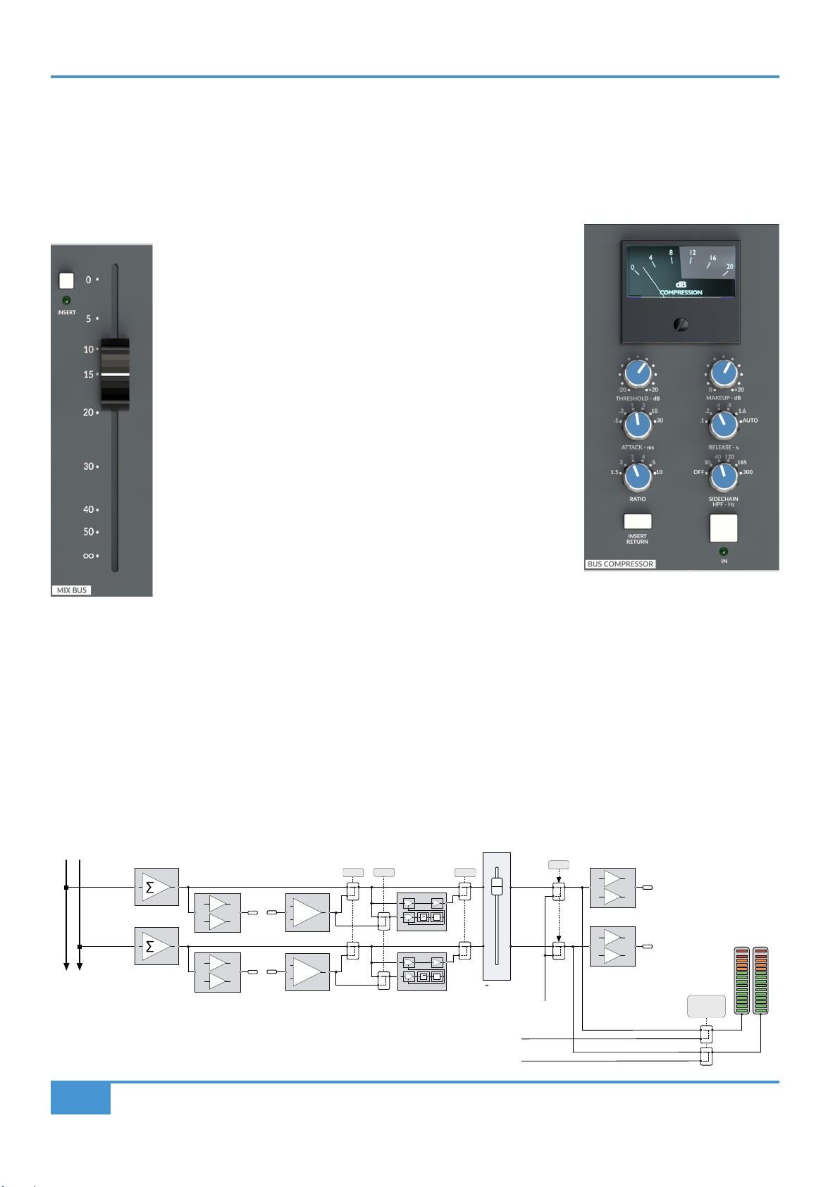
MIX BUS Fader
The main stereo MIX BUS fader is a 100mm high quality audio taper fader that controls the level of the main Mix Bus Out from the
console. The Mix Bus Fader is calibrated so that unity gain (0dB) is at the top of its travel. As can be seen in the block diagram
below, the fader follows the dedicated, balanced Mix Bus Insert Send and Return, which in turn is ahead of the classic SSL Bus
Compressor. An Oscillator inject is the last point in the Mix Bus signal ow, this inject is switched on using the TO MIX switch in
the Master Section OSCILLATOR controls.
MIX BUS Insert
ORIGIN's Mix Bus has a dedicated, fully balanced Insert Send and
Return. The Insert Send is always active, with the Insert Return being
switched into the Mix Bus circuit using the INSERT switch located next to
the Mix Bus fader (see picture left). This Insert is an ideal place to insert
mix bus processing devices such as SSL's Fusion.
MIX BUS COMPRESSOR
The classic SSL Bus Compressor in ORIGIN is a stereo compressor
applied across the Main Mix bus that uses exactly the same classic
design as the original unit found on the SL4000 G-Series console released
in 1989 (which in-turn was evolved from the earlier E-Series consoles).
The ‘soft’ knee point of the compressor, ie. the level at which compression
starts to take place, is set by the THRESHOLD control (±20dB). This is
intentionally designed to change depending on the setting of the RATIO
control; decreasing the RATIO setting lowers the effective threshold,
hence maintaining the perceived ‘loudness’ of the compressed signal.
The RATIO switch has six settings, 1.5:1, 2:1, 3:1, 4:1, 5:1 and 10:1. ATTACK time is switchable in six steps between 0.1 and
30 ms, and the RELEASE time is selectable between 0.1 and 1.6 seconds in ve steps. The AUTO release selection adjusts the
release time according to the signal envelope. The gain MAKEUP simply acts as a level control to compensate for the lowered
level that is a consequence of compressing the signal. This control may be set so as not to change the overall output level when
the compressor is switched in.
The compressor features a classic ‘dominant’ sidechain architecture. The left and right channels are independently rectied using
a true peak full wave detector circuit, and the dominant (loudest) channel controls the gain reduction of the overall stereo level
via the user selected time constants.
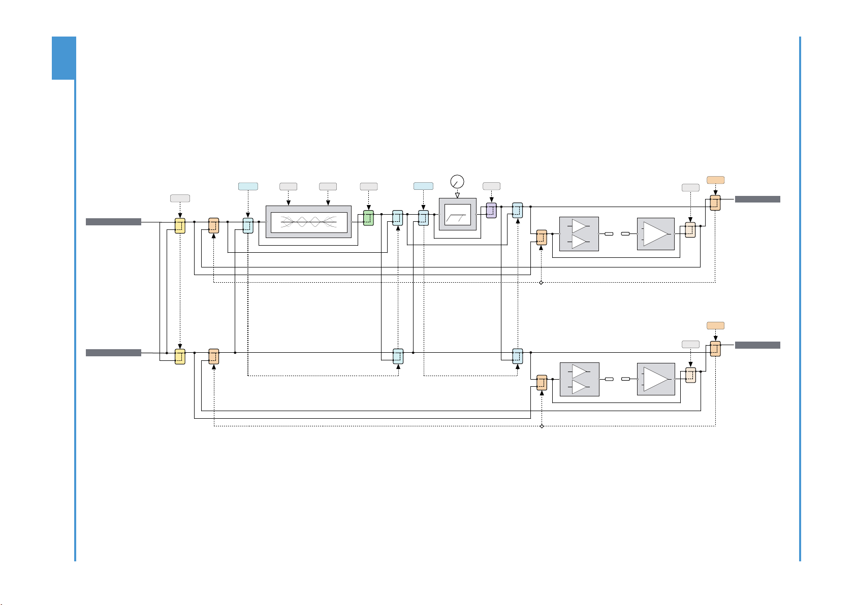
Block Diagram of the main Mix Bus section
+
-
+
-
IN
+
-
+
-
BUS COMP
+
-
+
-
MIX L OUT
MIX R OUT
Main Mix Bus
MIX METER
FOLLOW MON
SOURCE
IN
S/C
VCA
INSERT
VCA
S/C
VCA
VCA
KEY
INSERT INSERT COMP
to 0dB
TONE
SLATE
From MON L
From MON R
SLATE
SIGNAL
STEREO
MIX
BUS
L R
STEREO
MIX
METERS
L R
ORIGIN User Guide
Origin Master Section
27
As an enhancement to the earlier design, the ORIGIN Mix Bus Compressor has a
2nd order SIDECHAIN HPF (High Pass Filter) with 5 selectable lter frequencies (30,
60, 120, 185 and 300 Hz). Using this control to remove bass frequencies from the
sidechain reduces pumping effects when bass heavy mix bus signals 'dominate' the
action of the compressor.
The 'Key from INSERT RETURN' feature switches the sidechain source from the
Mix Bus path to the Mix Bus Insert Return allowing an independent key of the Bus
Compressor.
The illuminated COMPRESSION meter displays gain reduction in dB.
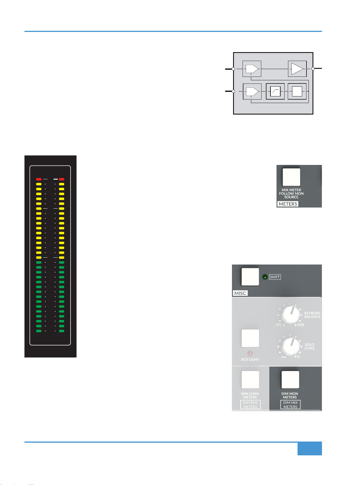
MIX Bus Meter
The 32 segment LED stereo MIX Bus Meter normally measures directly across the Mix L and Mix R outputs (as seen in the block
diagram on the previous page). There is a switch in the METERS controls in the Master Section (see
page 31) which changes the MIX Meter to follow the monitor source selection (pre
Monitor Level Control, but post AFL/PFL selection). This provides a useful way to
meter other sources on the MIX meter or meter selections from AFL/PFL.
Another useful use for this meter is monitoring/setting Oscillator levels as this meter
is fed directly when the Oscillator TO MIX function is selected (see page 32).
The fast response peak meter has dened markings for +24 dBu and +18 dBu as well as 0 dBu. The meter
has a fast ‘peak’ response and a slower release time to meter peaks while still showing useful signal levels.
The Mix Meter brightness may be 'dimmed' by holding the MISC section 'SHIFT' switch and simultaneously
pressing the METERS section 'DIM MON METERS' switch.
BUS COMP
S/C
VCA
VCA
BUSES/STEREO SUBGROUPS
O R I G I N
24
23
22
21
20
19
18
15
12
9
6
4
0
4
6
8
10
12
15
18
21
25
28
32
L R
dBu
24
23
22
21
20
19
18
15
12
9
6
4
0
4
6
8
10
12
15
18
21
25
28
32
A
1 2
24
23
22
21
20
19
18
15
12
9
6
4
0
4
6
8
10
12
15
18
21
25
28
32
L R
dBu
B
3 4
24
23
22
21
20
19
18
15
12
9
6
4
0
4
6
8
10
12
15
18
21
25
28
32
L R
dBu
C
5 6
24
23
22
21
20
19
18
15
12
9
6
4
0
4
6
8
10
12
15
18
21
25
28
32
L R
dBu
D
7 8
24
23
22
21
20
19
18
15
12
9
6
4
0
4
6
8
10
12
15
18
21
25
28
32
L R
dBu
E
9 10
24
23
22
21
20
19
18
15
12
9
6
4
0
4
6
8
10
12
15
18
21
25
28
32
L R
dBu
F
11 12
24
23
22
21
20
19
18
15
12
9
6
4
0
4
6
8
10
12
15
18
21
25
28
32
L R
dBu
G
13 14
L R
dBu
H
15 16
24
23
22
21
20
19
18
17
16
15
14
12
10
8
6
4
0
4
6
8
10
12
14
16
18
20
22
24
26
30
35
40
MIX
L R
dBu
ORIGIN User Guide
Origin Master Section
28
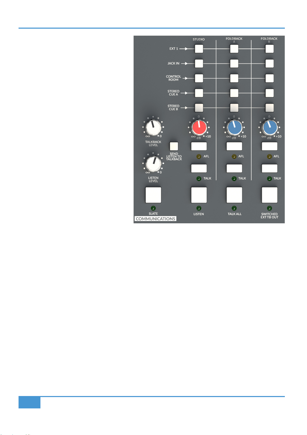
COMMUNICATIONS
As the name implies, the COMMUNICATIONS section
is the hub of how the control room communicates with
the artists and studio oor. The section is laid out
with three columns which represent the three main
destinations for the studio, namely FOLDBACK A,
FOLDBACK B and STUDIO. Typically FOLDBACK
A and FOLDBACK B are used to feed artist
headphones, while the STUDIO output is used to feed
loudspeakers in the performance area/studio oor.
For each of these three destinations there is a column
of 'source' switches. These connect the sources (listed
to the left of the switches) with the corresponding
destination. For example, pressing the STEREO CUE
A switch in the FOLDBACK A column will send the
Stereo Cue A bus to Foldback Output A.
Communications Source Options
EXT 1: Source connected to External 1
JACK IN: Source connected to the 3.5mm
Jack in the Monitor Section
CONTROL ROOM: The source selected in the MON
SOURCE section (see page 22)
STEREO CUE A: The Stereo Cue A bus (after the
master level control in the CUES
AND AUX MASTERS section, page 29)
STEREO CUE B: The Stereo Cue B bus (after the master level control in the CUES AND AUX MASTERS section, page 29)
TALKBACK and LISTEN LEVEL Controls
Under each column of the source selection switches there is a master level control for the three destinations. The STUDIO output
control is identied with a RED cap, with the Foldback outputs identied in BLUE. Details about the Talkback and Listen Mic inputs
can be found later in the guide (page 29).
AFL (After Fade Listen)
Underneath the level controls for each section there is an AFL switch. This feeds the appropriate communications output to the
AFL bus and forces the monitoring to switch to the AFL bus.
TALK
For each section there is an independent TALK switch. This sums the Talkback Mic signal to the corresponding communications
bus when pressed. This is a momentary switch with an automatic latch feature, i.e. if it is pressed and held it will act momentarily
(i.e. switch off when released), if it is pressed briey it will 'latch' on until pressed again. When the TALK feature is activated, by
default the monitors are also DIMmed. This interaction is programmable by holding down the TALK switch and simultaneously
pressing the DIM switch. This will link or unlink the DIM function to the TALK switch. This setting is remembered by the console
even when the console is powered down.
The Talkback Mic input connection and gain controls are detailed later in the guide (page 28).

ORIGIN User Guide
Origin Master Section
29
TALK ALL
TALK ALL is a grouped 'TALK' function. Typically this simultaneously activates the TALK function for all three communications
destinations. This is a momentary switch with an automatic latch feature (see previous paragraph). If it is pressed briey it will 'latch'
on until pressed again. The TALK ALL function is also programmable, holding down the TALK ALL switch and simultaneously
pressing a TALK switch (or LISTEN, or SEND LISTEN TO TALKBACK switches) will link or unlink the TALK function (and/or the
others) to the TALK ALL switch. This setting is remembered by the console even when the console is powered down.
The DIM function is not directly connected to the TALK ALL function. DIM will be activated if any of the functions connected to
TALK ALL have a DIM function attached.
LISTEN
The LISTEN switch switches the Listen Mic input into the control room monitoring. The Listen Mic input connection and gain
controls are detailed later in the guide (page 29). Typically, the Listen Mic is an omnidirectional mic (or mics) located centrally on
the studio oor (e.g. mounted on the ceiling). The Listen Mic Input is connected to the Listen Mic Compressor (LMC). The LMC
circuit is designed to allow a microphone connected to the Listen Input to maintain similar level signals regardless of whether the
source is close or distant. i.e. if an artist is close to the microphone and another artist is distant from it, the Listen Mic and LMC
will allow the control room to hear both artists legibly and at a similar level. This is a momentary switch with an automatic latch
feature, i.e. if it is pressed and held it will act momentarily (i.e. switch off when released), if it is pressed briey it will 'latch' on until
pressed again.
The LISTEN function can be connected (or disconnected) to the TALK ALL function by pressing and holding the TALK ALL switch
and simultaneously pressing the LISTEN switch. When the TALK ALL switch is released, the LISTEN switch will now be linked to
it. Repeating this operation will unlink the function.
SEND LISTEN TO TALKBACK
This feature connects together the Talkback and Listen Mic signals to allow a simple 'conference' system. This can be useful where
the Listen Mic is a convenient way for all artists in the session to talk to each other. For example, a session with musicians on the
Studio Floor, some in the Control Room and others in Isolation Booths. Using the Listen and Talkback features with SEND LISTEN
TO TALKBACK feature enabled would allow everyone to converse with one another.
CAUTION: If this feature is used with a listen mic in the same room as the talkback destination (e.g. studio loudspeakers, or loose
headphones), there is potential for feedback/howlround from the combination of the Listen Mic, TALK button and the STUDIO
output.
SWITCHED EXT TB (External Talkback) OUT
When pressed, this sends the Talkback amplier output directly to the DB-25 connector on the rear of the console (and potentially
then to a patchbay, if one is connected). This is useful when you want to use the Talkback circuits to feed external devices such
as a third party artist cue mix system. This is a momentary switch with an automatic latch feature, i.e. if it is pressed and held it will
act momentarily (i.e. switch off when released), if it is pressed briey it will 'latch' on until pressed again.
The Switched External Talkback function can be connected (or disconnected) to the Talk All function by pressing and holding the
TALK ALL switch and simultaneously pressing the SWITCHED EXT TB OUT switch. When the TALK ALL switch is released, the
SWITCHED EXT TB OUT switch will be linked to it. Repeating this operation will unlink the function.
SLATE
When pressed, this momentary only switch sends the Talkback signal directly to the all of 16 track Bus Outputs and to the main
stereo Mix Bus Output, replacing the signals that are feeding those outputs and CUTting the Main Monitor. Traditionally this function
was used to place a 'take marker' (e.g. "This is Take 1") onto the recorder attached to the Bus and/or Mix console outputs.
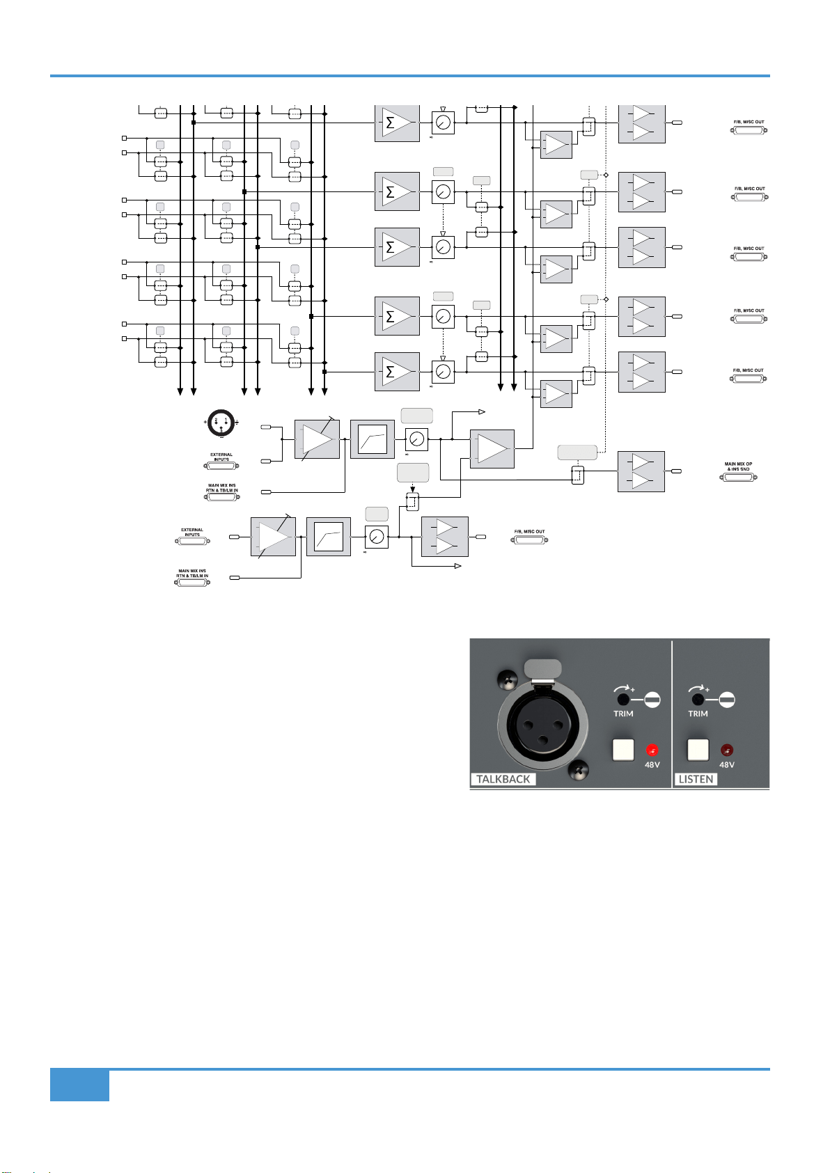
A block diagram of the communications section is shown on the next page.
ORIGIN User Guide
Origin Master Section
30
TALKBACK and LISTEN MIC
In the image on the right we can see the TALKBACK and LISTEN
sections in the Master Section. The TALKBACK section has an XLR input
for a Master Section mounted (or connected) Talkback Microphone, a
hole for a at blade trim tool to access and adjust the gain trim setting for
the Talkback microphone input and a +48V phantom power switch for the
input. Similarly the LISTEN section has a hole for a at blade trim tool to
access and adjust the gain trim setting for the Listen Microphone Input
and a +48V phantom power switch.
Talkback Microphone Connections (Mic and Line Inputs)
The Talkback Amplier has a front panel XLR connector, as shown in the picture above, it also has a paralleled connection on the
"EXTERNAL INPUTS" DB-25 rear connector if an externally located Talkback mic is desirable. If this DB-25 input is connected to
a patchbay, it allows the external Talkback Mic Amp to be over patched.
After the Talkback Mic Pre gain stage there is a second, summed, line-level input available on the "MAIN MIX INS RTN & TB/LM
IN" DB-25 rear connector. This can be seen in the lower half of the block diagram above. This allows an externally amplied Mic
Pre signal to be fed through the Talkback Mic Compressor (This is the same circuit as the infamous SSL Listen Mic Compressor).
With the SWITCHED EXT TB OUT switch pressed in the COMMUNICATIONS part of the Master Section, there is a Talkback Mic
output signal on the "MAIN MIX OP & INS SEND" DB-25 rear connector (and on the patchbay, if connected), this gives an input and
output path to use this compressor creatively. If you are using this feature, don't forget to disconnect, or over patch the Talkback
Mic Amp connections to prevent the talkback mic signals being summed with the external Line input!
SWITCHED
EXT TB OUT
EXT 4L
EXT 4R
C/ROOM L
C/ROOM R
CUE AL
CUE AR
CUE BL
CUE BR
to +10dB
+
-
EXT 1L
EXT 1R
to +10dB
LEVEL
AFL
+
-
+
-
to +10dB
LEVEL
AFL
+
-
+
-
STUDIO L OUT
STUDIO R OUT
+
TALKBACK MIC
FRONT PANEL TRIM
(+40 to +65dB)
dB
+
-
TALKBACK
MIC
INPUT
LISTEN
MIC
INPUT
+
-
SEND
LISTEN TO
TALKBACK
LISTEN
OUT
LISTEN
(Feed To Monitor Section)
+
F/BACK AR OUT
F/BACK BL OUT
F/BACK BR OUT
+
+
TALK
+
+
TALK
TALKBACK
LEVEL
to 0dB
SLATE
LISTEN
LEVEL
to 0dB
+
-
EXT TB OUT
≥1
LISTEN
FRONT PANEL TRIM
+40 to +65dB
TALKBACK
COMPRESSOR
LISTEN
COMPRESSOR
TALKBACK
LINE
INPUT
LISTEN
LINE
INPUT
FRONT
PANEL
XLR
dB
+
-
ORIGIN User Guide
Origin Master Section
31
Listen Microphone Connections (Mic and Line Inputs)
The Listen Mic Amplier connection is on the "EXTERNAL INPUTS" DB-25 rear connector. If this DB-25 input is connected via a
patchbay, it allows the Listen Mic Amp to be over patched.
As with the Talkback Mic, after the Listen Mic Pre gain stage there is a second, summed, line-level input available on the "MAIN
MIX INS RTN & TB/LM IN" DB-25 rear connector. This can be seen in the lower half of the block diagram on the previous page. This
allows an externally amplied Mic Pre signal to be fed through the Listen Mic Compressor (This is the same circuit as the infamous
SSL Listen Mic Compressor of Hugh Padgham/Peter Gabriel's Intruder snare sound fame). There is a Listen Mic output signal on
the "F/B, MISC OUT" DB-25 rear connector (and on the patchbay, if connected). This gives an input and output path to use this
compressor creatively. If you are using this feature don't forget to disconnect, or over patch the Listen Mic Amp connections to
prevent the Listen mic signals being summed with the external Listen Line input!
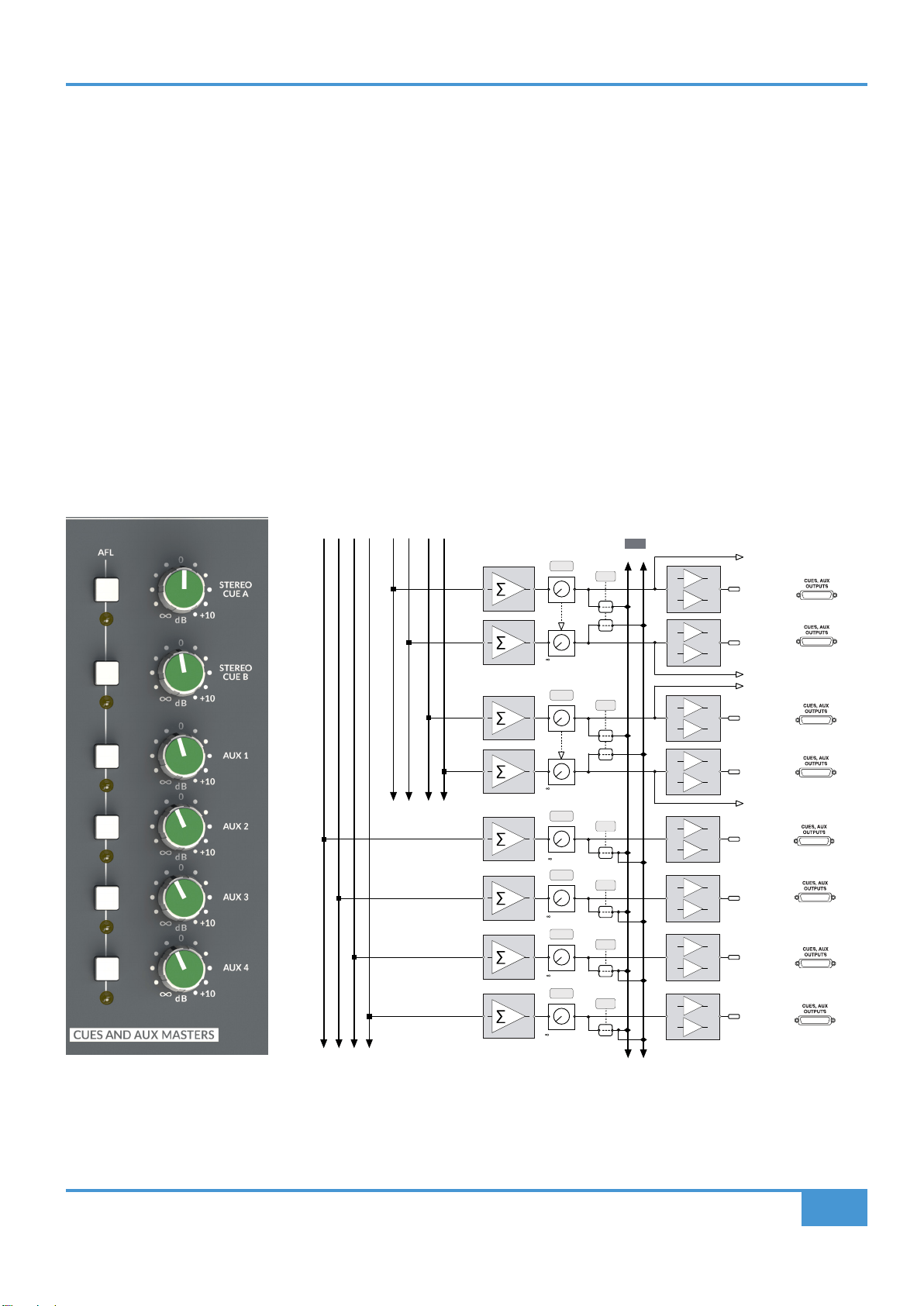
CUES AND AUX MASTERS
This section has the master level controls for the A and B Stereo Cue Mix buses and mono Aux buses 1-4. AFL switches the
selected signal into the Monitor section to allow the selected bus to be auditioned.
to +10dB
LEVEL
L R
L R
AFL
AFL
+
-
+
-
CUE AL OUT
CUE AR OUT
to +10dB
LEVEL
AFL
+
-
+
-
CUE BL OUT
CUE BR OUT
LEVEL
AFL
+
-
AUX 1 OUT
LEVEL
AFL
+
-
AUX 2 OUT
LEVEL
AFL
+
-
AUX 3 OUT
LEVEL
AFL
+
-
AUX 4 OUT
CUE AL
CUE AR
CUE BL
CUE BR
to +10dB
to +10dB
to +10dB
to +10dB
MONO AUX BUSES
1 2 3 4
STEREO CUE BUSES
AL AR BL BR
ORIGIN User Guide
Origin Master Section
32
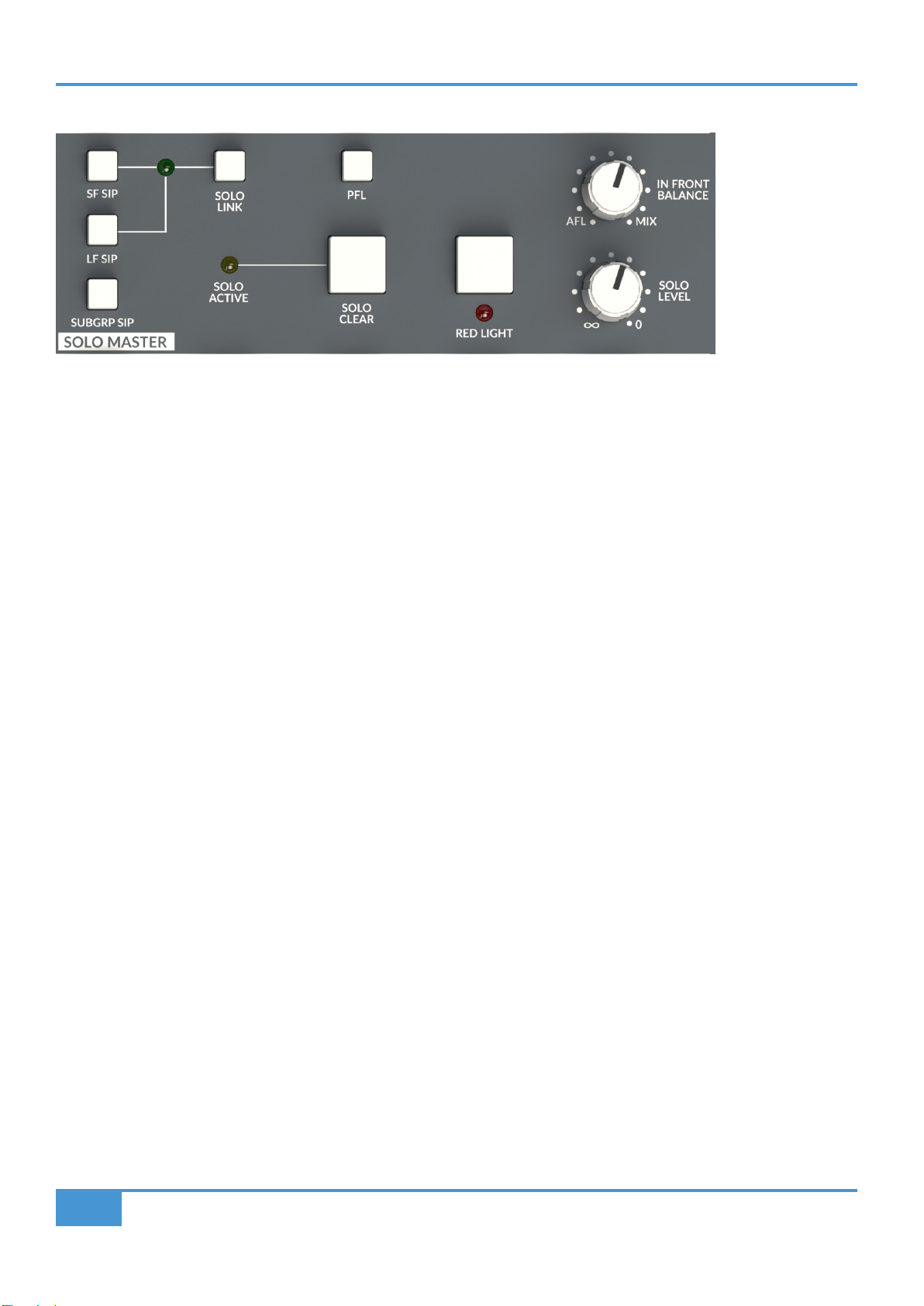
AFL, PFL and the SOLO MASTER Section
ORIGIN has a comprehensive and exible After Fade Listen, Pre Fade Listen (AFL/PFL) and Solo In Place (SIP) system. With no
options selected, the SOLO switches in the console channel strips activate the AFL function, i.e. they send the selected path to the
stereo AFL bus and the monitoring switches to output the AFL bus. The benet of this approach is two fold, it is non-destructive,
i.e. any paths being used to track or mix will not be Cut by the use of the Solo switch, and also it allows the selected path, or paths
to be listened to against the Mix Bus signal, using the IN FRONT BALANCE control.
SF SIP (Solo In Place), LF SIP, SUBGRP SIP and SOLO LINK
If a destructive Solo would be preferred to AFL, then the SIP (Solo In Place) switches are used to link the Solo and Cut actions.
These SIP functions are split into separate options for the Large Fader (LF SIP), Small Fader (SF SIP) and Subgroup (SUBGRP
SIP) sections of the console. This allows the different sections to be in different modes, for example, if the Small Fader paths are
being used as sends to a recorder, it may be useful to have these in AFL mode so that a SOLO selection of any Small Fader
wouldn't CUT the send from any of the other Small Fader record paths.
The SOLO LINK switch connects together the Solo/Cut connections for both the Large Fader and Small Fader paths. SOLO LINK
active is indicated by a green LED at the intersection of the lines linking the SIP functions. For SOLO LINK to be active, both LF
SIP and SF SIP switches must be in the same mode (i.e. both pressed, or both unpressed), if one of these is not pressed, the LED
will not illuminate and SOLO LINK will not be active.
SOLO ACTIVE and SOLO CLEAR
Whenever a console SOLO or AFL function is active the yellow SOLO ACTIVE LED will illuminate. Any active SOLO or AFL
functions can be cancelled using the SOLO CLEAR switch. When this is pressed, the SOLO ACTIVE LED will extinguish.
PFL (Pre Fade Listen)
Selecting PFL will change the default After Fade Listen (AFL) mode to Pre Fade Listen, i.e. Solo'd signals will be sent Pre Fader
to the Monitoring. Switches labelled AFL (such as those in the Stereo Return section) will always be AFL and are not affected by
the PFL selection.
SOLO LEVEL
This control adjusts the level of either the AFL signal or the PFL signal (depending on whether the PFL switch is selected).
IN FRONT BALANCE
In default mode (i.e. Not SIP or PFL) Pressing a channel SOLO switch routes a mix of the AFL signal and the selected left and right
monitor sources to the monitor outputs. The IN FRONT BALANCE level control adjusts the balance between AFL signal and MIX
in the Monitors. This is useful, for example, to EQ a source in context with the Mix and not in isolation. The IN FRONT BALANCE
control is adjusted to taste to give a useful balance depending on the source being listened to.
ORIGIN User Guide
Origin Master Section
33
NOTE : If the IN FRONT BALANCE control is left fully clockwise (i.e. an all mix bus balance) then it may appear that
the AFL/Solo function isn't working as there is no AFL signal feeding the monitoring, (i.e. you're only listening to the
mix bus signal, i.e. no AFL/Solo signal)!
RED LIGHT
The RED LIGHT function closes a relay on the DB-9 UTILITY connector on the rear panel of the console. Typically this is used for
a Record Light for the studio, to indicate not to disturb the recording area. If nothing is connected to the UTILITY connector, then
this switch has no function (other than illuminating the associated red front panel LED!). The RED LIGHT relay switch closure will
change state when the console goes to SLEEP. This could be used to switch off other studio equipment, or to signal externally that
the console is in sleep mode, if the RED LIGHT function is not required.
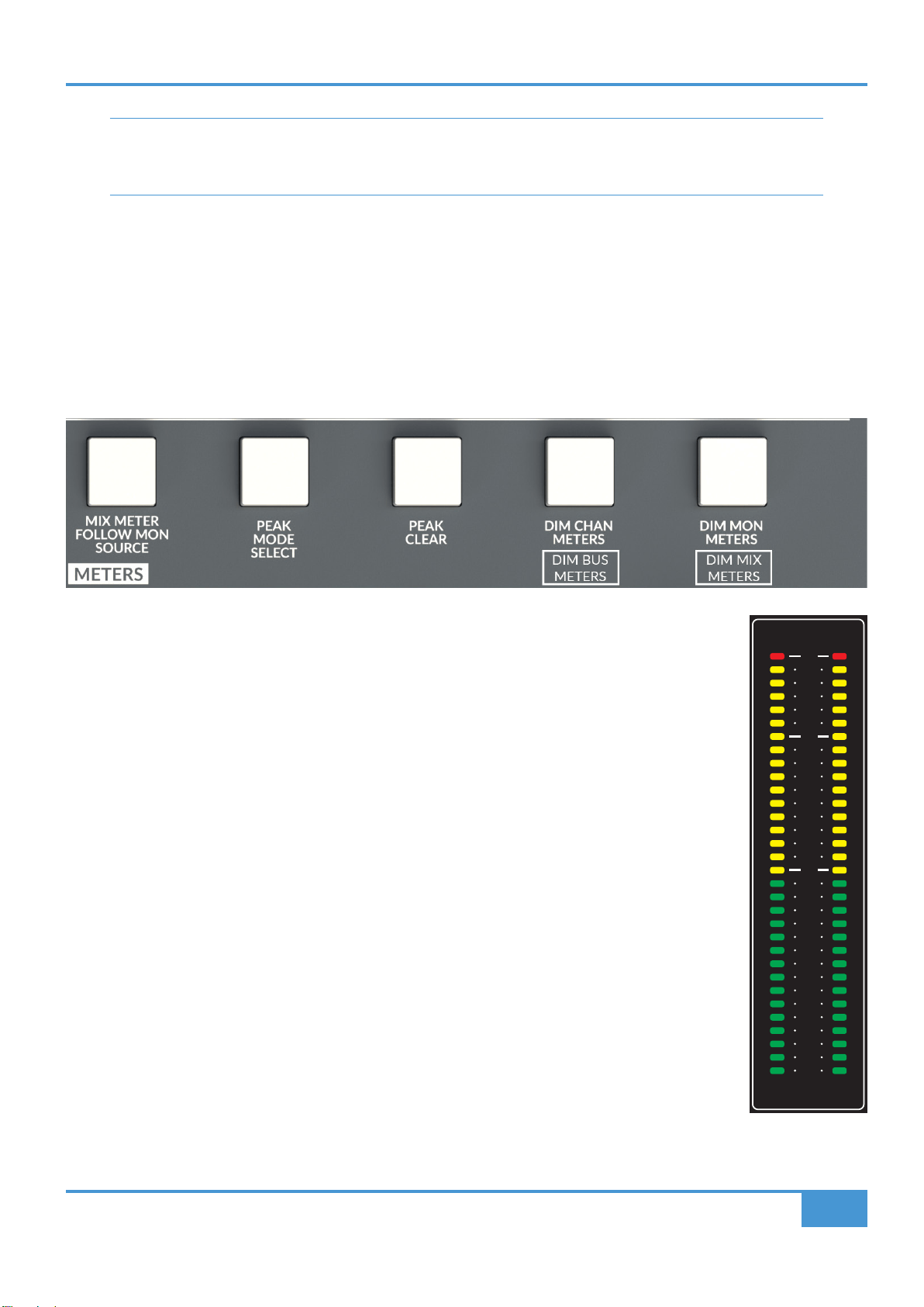
METERS Section
MIX METER FOLLOW MON SOURCE
The MIX meter typically shows the level of the main stereo Mix bus. Pressing the MIX METER FOLLOW MON
SOURCE switch switches the MIX meter to follow the selection on the MON SOURCE section. This is useful
to meter, or calibrate an external source connected to one of the four External Source selectors.
PEAK MODE SELECT
The meters in ORIGIN are fast detecting 'peak' meters. These meters have some options for displaying peaks
and the PEAK MODE SELECT switch cycles around these modes with repeated pressing. The options are:
- No Peak Hold. The meter displays instantaneous peak values only
- First Press - 1 second Peak Hold. Peak level LED stays illuminated for approximately 1 second and
then automatically resets. This mode can be identied when selected by the red +24dBu LEDs
illuminating for approx. 1 second and then falling to the current metered level.
- Second Press - 3 second Peak Hold. Peak level LED stays illuminated for approximately 3 seconds
and then automatically resets. This mode can be identied when selected by the red +24dBu LEDs
illuminating for approx. 3 seconds and then falling to the current metered level.
- Third Press - Permanent Peak Hold. The LED indicating Peak level achieved stays illuminated
indenitely and can be reset using the PEAK CLEAR function (see below). This mode can be identied
when selected by the red +24dBu LEDs rippling across 8 channel sections.
- Fourth Press - returns to the no Peak Hold state.
The console will remember the setting when powered off, so the start state for the rst press may be offset
(e.g. if in 1 second Peak hold when powered off, the next press after power on will be 3 second.)
PEAK CLEAR
Resets the captured Peak level (and indication) for all meters when permanent Peak Hold mode is selected (see PEAK MODE
SELECT above).
BUSES/STEREO SUBGROUPS
O R I G I N
24
23
22
21
20
19
18
15
12
9
6
4
0
4
6
8
10
12
15
18
21
25
28
32
L R
dBu
24
23
22
21
20
19
18
15
12
9
6
4
0
4
6
8
10
12
15
18
21
25
28
32
A
1 2
24
23
22
21
20
19
18
15
12
9
6
4
0
4
6
8
10
12
15
18
21
25
28
32
L R
dBu
B
3 4
24
23
22
21
20
19
18
15
12
9
6
4
0
4
6
8
10
12
15
18
21
25
28
32
L R
dBu
C
5 6
24
23
22
21
20
19
18
15
12
9
6
4
0
4
6
8
10
12
15
18
21
25
28
32
L R
dBu
D
7 8
24
23
22
21
20
19
18
15
12
9
6
4
0
4
6
8
10
12
15
18
21
25
28
32
L R
dBu
E
9 10
24
23
22
21
20
19
18
15
12
9
6
4
0
4
6
8
10
12
15
18
21
25
28
32
L R
dBu
F
11 12
24
23
22
21
20
19
18
15
12
9
6
4
0
4
6
8
10
12
15
18
21
25
28
32
L R
dBu
G
13 14
L R
dBu
H
15 16
24
23
22
21
20
19
18
17
16
15
14
12
10
8
6
4
0
4
6
8
10
12
14
16
18
20
22
24
26
30
35
40
MIX
L R
dBu
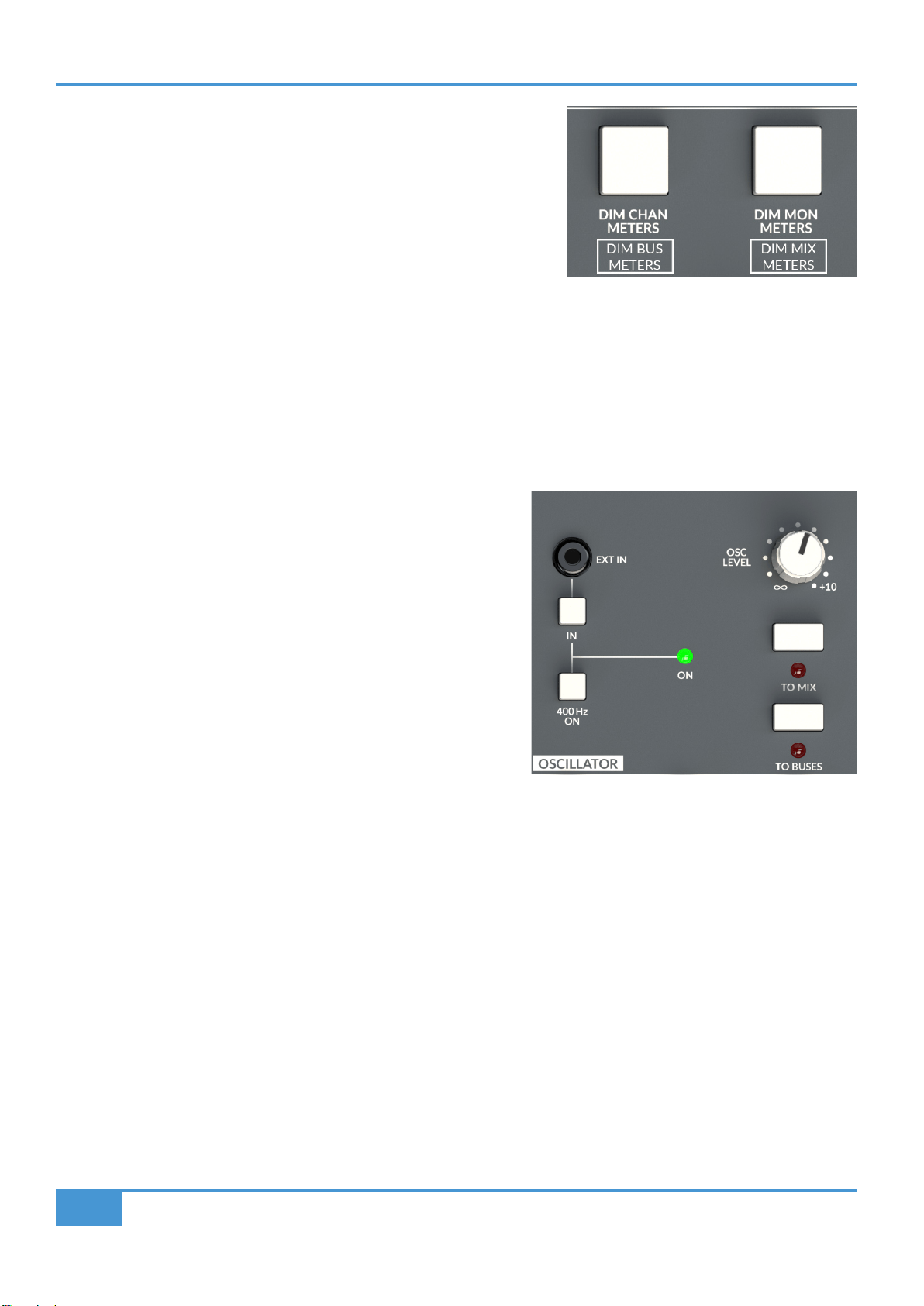
ORIGIN User Guide
Origin Master Section
34
OSCILLATOR
ORIGIN has a simple, yet exible OSCILLATOR section. It is designed to take advantage of the power of modern hand held
devices and the software applications available for them.
400 Hz ON and EXT IN
The in-built sine wave oscillator is xed to 400Hz. This frequency was
chosen over the more typical 1kHz as it's easier on the ear when listened
to for prolonged periods, such as when doing alignment or signal level
checks. The 400Hz ON switch enables the Oscillator and sends this signal
to the rear F/B, MISC OUT DB-25 connector on the rear of the console, and
typically from there to the patchbay. The internal Oscillator may be over-
ridden by selecting the IN switch for any source connected to the 3.5 mm
Jack EXT IN socket immediately above it. This is designed to allow an
external signal source to be connected such as a tablet or mobile phone,
typically running an application to generate test signals or sweeps.
OSC LEVEL
The OSC LEVEL control adjusts the level of the Oscillator, both the internal Oscillator and the external input.
TO MIX and TO BUSES
These switches send the Oscillator (or EXT IN) signal to the 16 track buses (TO BUSES) or the stereo Mix bus (TO MIX). Either of
these selections over-ride the default signals being fed to the respective outputs, so take care not to press them when recording
from these outputs..
The MISC Section
ORIGIN's MISC section is the home for a variety of functions.
SHIFT/ CLEAR ROUTE
The bottom switch in the MISC switch section has two basic functions which depend on the context of it being pressed.
SHIFT
The SHIFT switch provides secondary or setup functions to some of the switches in the Master Section.
DIM CHAN METERS and DIM BUS METERS
ORIGIN has high brightness LED meters. It may be useful to reduce the
brightness of the meters when lighting conditions, or what the user focuses on,
needs to change. The DIM CHAN METERS switch switches between bright and
dim CHAN meters (above the channel paths), When this switch is pressed with
the MISC section SHIFT switch, the BUSES/STEREO GROUP meters change
brightness.
DIM MON METERS and DIM MIX METERS
Similar to the previous item, the DIM MON METERS switch switches between bright and dim MON meters (above the console
channels), When this switch is pressed with the MISC section SHIFT switch, the MIX meter changes brightness.
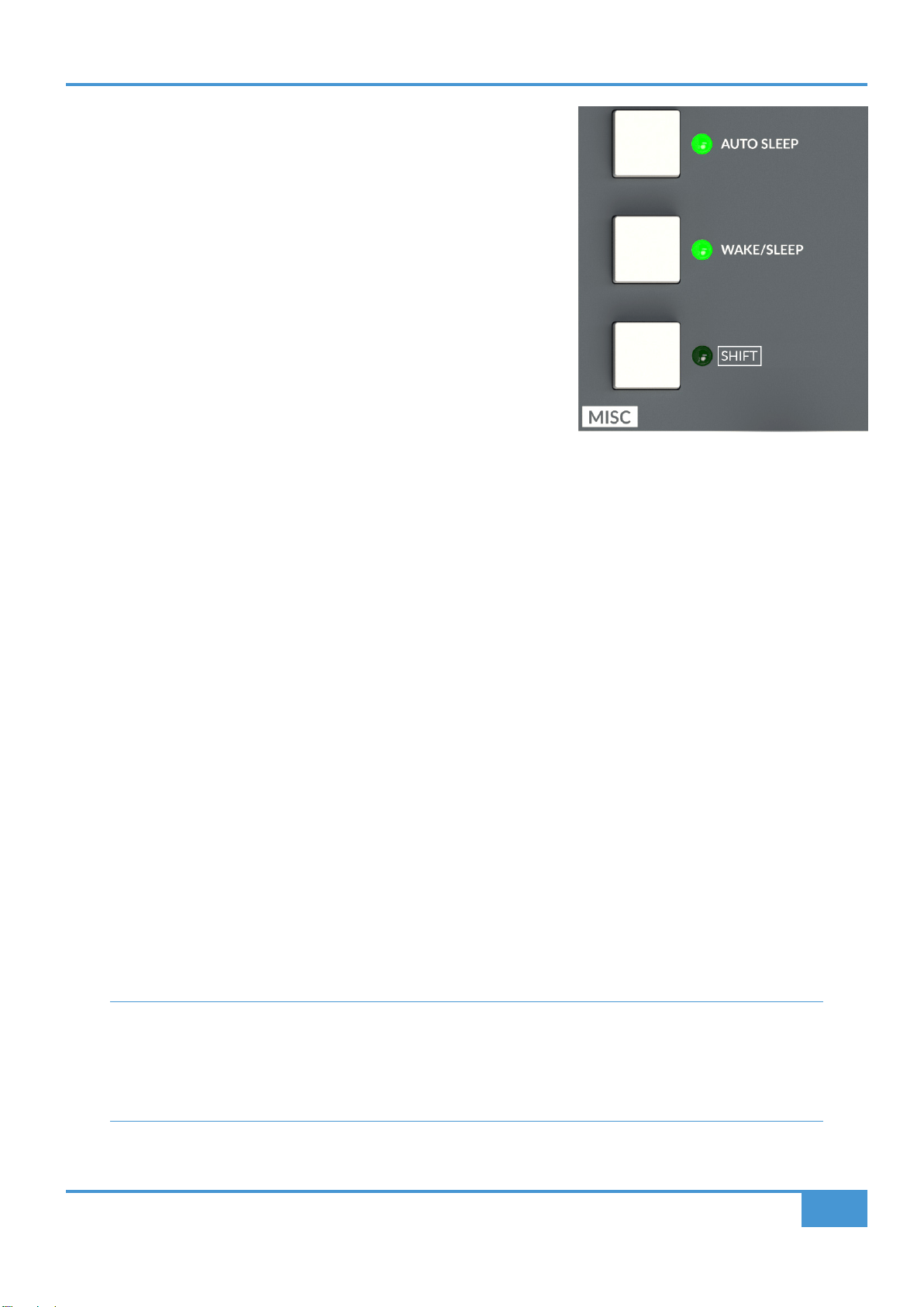
ORIGIN User Guide
Origin Master Section
35
For the METERS section, the Secondary functions are identied by a white outline
around the switch label, such as the DIM MIX METERS function. Pressing SHIFT
and the respective switch simultaneously activates the secondary function.
CLEAR ROUTE
The SHIFT switch also has some interaction with the Track Bus Routing functions.
When a channel or a bus is in Route Select mode (ashing blue LED) pressing
SHIFT will escape back to the normal console state. i.e. it acts to cancel/clear
Route Select function.
If SHIFT is pressed and held down and a ROUTE switch selected, either in a
Channel, Stereo Return or in the the Buses section, then routes to and/or from the
selected path will be cleared. (see Appendix A)
Power Management Tools
ORIGIN is designed with some clever and useful tools to help manage the power requirements of the console. Older analogue
consoles (and other studio devices) typically don't like being switched on and off. This is partly because of the heat/cool cycles
causing issues with components such as valves(tubes), transformers, relays and capacitors. Additionally because of the electrical
stresses caused by inrush currents when large linear power supplies are switched on. For these reasons, many older studio
consoles are left on 24 hours a day with the associated cooling/air conditioning plant also running at the same time. ORIGIN's
circuitry and power supplies are designed to be powered on and off under the control of the console's Power Management Tools.
This allows the console to be regularly powered on and off without issue and hence we have provided a WAKE/SLEEP switch and
an AUTO SLEEP function to provide a timed power down along with simple switches for this useful feature.
AUTO SLEEP and WAKE/SLEEP
Origin can be put into Sleep mode by pressing and holding the WAKE/SLEEP switch for approximately 3 seconds. When the
console is in Sleep mode, the WAKE/SLEEP LED will pulse smoothly at about 1 pulse per second. The console can be awoken
from Sleep by pressing the WAKE/SLEEP switch.
When the console enters 'Sleep' mode it carries out a controlled power down sequence. The Monitor Output Relays disconnect
the Monitor Loudspeakers, next the Master Section powers down with a controlled shutdown of the power rails, shortly followed by
the power rails for the console channels. Similarly when waking, the power up sequence is controlled. This means that monitors
left powered and connected are not affected by loud thumps caused by sudden circuit activation in the console.
The AUTO SLEEP switch enables the Auto Sleep function which monitors meter activity. If no activity is detected over a preset
amount of time (15 seconds to 75 minutes, see Appendix B - Setup Functions), the console automatically enters Sleep mode. As
above, when the console is in Sleep mode, the WAKE/SLEEP LED pulses smoothly at about 1 pulse per second and the console
can be awoken from Sleep by pressing the WAKE/SLEEP switch. Approximately 60 seconds before the Sleep mode is activated
the WAKE/SLEEP LED ashes quickly to indicate the console is about to go to sleep.
How it works - The console detects activity on any of the LED meters and/or the Routing/Talkback/Comms/Meter
switch functions to detect the console is in use. If no activity is detected for a preset period, the console can enter
a 'Sleep' state, where the bare minumum of circuitry is powered and the console is ready at any moment to Wake to
its pre-sleep state. When in Sleep mode ORIGIN consumes approximately 4% of the power needed in its wake state
(approximately 40 W in sleep state and <1 kW in its wake state).
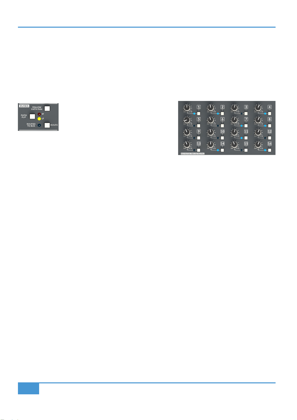
ORIGIN User Guide
Appendix A
36
Appendix A - ORIGIN Advanced Routing
ORIGIN is equipped with 16 buses, these buses are 'normally' connected in odd/even pairs to the 8 Stereo Group Buses. This
connection may be directly connected via DB25 connectors on the rear panel, or more typically, connected via half-normalled
connections on a patchbay for the console.
Typically on older analogue consoles, the track routing switches were located at the top of the channel strip, in ORIGIN we have
used some clever routing switching to minimise the amount of channel depth (and back stretching!) used for the routing feature
while at the same time adding a powerful and elegent way to route paths to buses.
The key to routing to track buses with ORIGIN is using
the ROUTE switch in the BUSES section of the channel
strip (or a Stereo Return).
This works with the switches in the BUS TRIM MASTERS AND ROUTING
section in the centre section of the console.
Routing Terms
Channel(s): a path or group of paths from which the signal can be routed from. Note: Includes Stereo Returns.
Crosspoint: (or Routing Crosspoint), the audio connection between Channel and Track Bus.
Idle Mode: mode in which no selection is active, this is the 'normal' state for the routing system.
Range Routing: the act of modifying Crosspoints for a range of Channels or Track Buses.
Range Selection: the act of selecting a range of paths or Track Buses.
Select Mode: Indicated by Blue Flashing LED(s). The routing system state to create or remove routes (Crosspoints)
Track Bus or Buses: The 16 summing buses that Channels can be routed to.
From Channel(s): Routing starting with the Channel or Channels and routing TO a Track Buses or Track Buses
To Bus(es): Routing starting with the Track Buses or Track Buses and routing FROM a Channel or Channels
'From Channel' Routing - The typical approach for Analogue Consoles
In a typical older analogue console the routing from channels to buses is done with 'routing switches' in the channel strip. The
routing in ORIGIN can be used in exactly the same way.
Simple Channel to Bus Routing
Starting with the simplest case of routing a Channel to a single Track Bus...
Press the ROUTE switch in the BUSES section on the Channel you wish to route from, this will put the Channel into Select Mode
and ash the ROUTED TO BUS LED in the Channel, you now use the switches in the BUS TRIM MASTERS AND ROUTING centre
section panel to select which Track Bus this channel strip will route to e.g. Track Bus 1. When the switch next to the Track Bus
is pressed the corresponding Track Bus blue LED will brightly illuminate to indicate that the channel strip is routed to Track Bus
1. When the ashing channel strip ROUTE switch is pressed again, the LED in the BUS TRIM MASTERS AND ROUTING section
stays dimly illuminated to show the Channel is routed to a Track Bus and the Channel ROUTED TO BUS LED will also stay dimly
illuminated to indicate that a Channel is routed to Track Bus 1.
Routing to Multiple Buses
As with the simple case above, the same process can be used to route a Channel to multiple Track Buses...
Press the ROUTE switch in the BUSES section on the Channel you which to route from, this will put the Channel into Select Mode
and ash the ROUTED TO BUS LED in the Channel, you now use the switches in the BUS TRIM MASTERS AND ROUTING centre
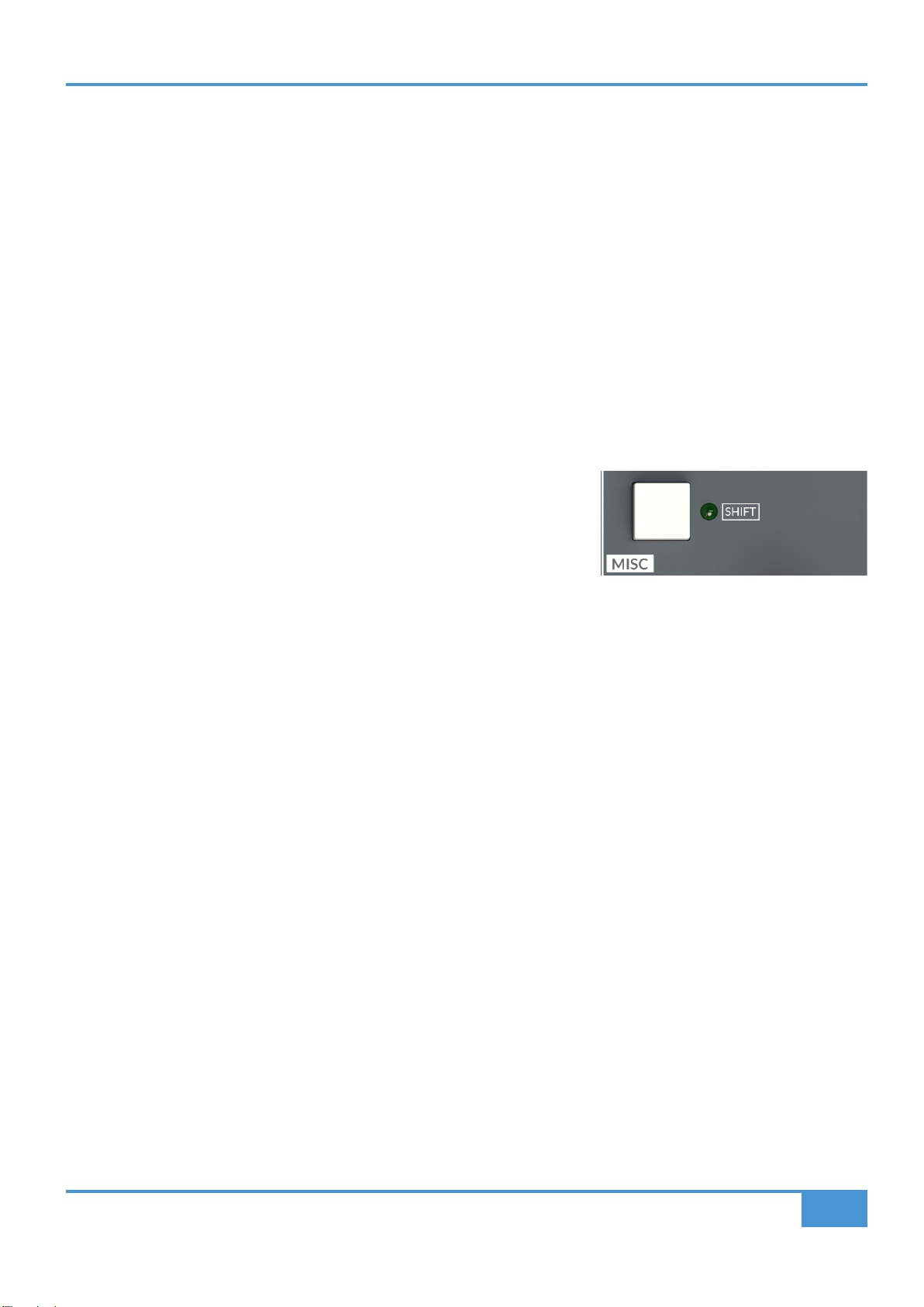
ORIGIN User Guide
Appendix A
37
section panel to select multiple Track Buses this channel strip will route to e.g. Track Bus 1, 2, 3 and 4. When the switch next to the
Track Bus is pressed the corresponding Track Buses blue LED will brightly illuminate to indicate that the channel strip is routed
to Track Buses 1 to 4. When the ashing channel strip ROUTE switch is pressed again, the LEDs in the BUS TRIM MASTERS
AND ROUTING section stays dimly illuminated to show the Channel is routed to Track Buses and the Channel ROUTED TO BUS
LED will also stay dimly illuminated to indicate that a Channel is routed to Track Buses 1 to 4.
Range Routing - more channels to more buses with less switch presses!
In the previous example, instead of pressing multiple Track Bus switches for buses 1 to 4 it is possible just to simultaneously press
Track Bus switches 1 and 4 to route to a range of Track Buses simultaneously.
Similarly to route a range of Channels to multple Track Buses it is possible to use a Range Selection of Channel ROUTE switches
to route from multiple Channels to a Track Bus or Track Buses.
A good example of this might be routing a range of Channels to a pair of Track Buses, for example to make a Drum stem, or
submix from eight channels of drum mic's on Channels 1 to 8 mixed to Track Buses 1 and 2. To do this, use a range of Channel
ROUTE switches on channels 1 to 8 by simultaneously pressing the ROUTE switches on Channel 1 and Channel 8. This should
now put Channels 1 to 8 into Select Mode and the Channel Blue ROUTE LEDs
ashing. Now by pressing Track Bus switches 1 and 2 simultaneously, all eight
Channels will be routed to Track Buses 1 and 2. To return to Idle Mode (dimmed
LEDs) from Select Mode(ashing and bright LEDs) you can now press the Range
Selection of Channels 1 to 8 again, or more simply press the Master Section SHIFT
switch to escape from Range Selection mode.
'To Bus' Routing - The other (more logical!) approach to routing
Having central, per Track Bus, routing select switches allows ORIGIN to provide a second way to route to Track Buses. This starts
from the bus, not from the Channel and in some ways is more logical once the principles are understood. Fundamentally with
this way of routing, it starts with putting the Track Bus into Select Mode, so routing starting with the Track Bus, not the Channel.
Simple Track Bus from Channel Routing
Starting with the simplest case of routing to a Track Bus from a single Channel...
Press the switch next to the chosen Track Bus, in the BUS TRIM MASTERS AND ROUTING section this will put the Track Bus
into Select Mode and ash the Track Bus LED next to the BUS TRIM knob, you now use the ROUTE switch in the BUSES
section of the Channel to select which Channel routes to this Track Bus. When the ROUTE switch in the Channel is pressed the
corresponding ROUTED TO BUS blue LED will brightly illuminate to indicate that the Channel is routed a Track Bus. When the
ashing Track Bus switch is pressed again, the LED in the BUS TRIM MASTERS AND ROUTING section stays dimly illuminated
to show the Channel is routed to a Track Bus and the Channel ROUTED TO BUS LED will also stay dimly illuminated to indicate
that a Channel is routed to a Track Bus.
Routing from Multiple Channels
As with the simple case above, the same process can be used to route multiple Channels to a Track Bus...
Press the switch next to the chosen Track Bus, in the BUS TRIM MASTERS AND ROUTING section this will put the Track Bus into
Select Mode and ash the Track Bus LED next to the BUS TRIM knob, you now use the ROUTE switches in the BUSES section
of a selection of Channels to select which Channels to route to this Track Bus. e.g. Channels 1, 2, 3 and 4. When the ROUTE
switched in each Channel is pressed the corresponding ROUTED TO BUS blue LEDs will brightly illuminate to indicate that the
Channels are routed the Track Bus. When the ashing Track Bus switch is pressed again, the LED in the BUS TRIM MASTERS
AND ROUTING section stays dimly illuminated to show Channels 1 to 4 are routed to the Track Bus and the Channel ROUTED
TO BUS LEDs will also stay dimly illuminated to indicate that those Channels are routed to a Track Bus.

ORIGIN User Guide
Appendix A
38
Range Routing 2 - more buses from more channels with less switch presses!
In the previous example, instead of pressing multiple Channel ROUTE switches for channels 1 to 4 it is possible just to
simultaneously press Channel ROUTE switches 1 and 4 to route to a range of Channels simultaneously.
Similarly to route to a range of Track Buses from multiple Channels it is possible to use a Range Selection of both Track Bus
switches and Channel ROUTE switches.
Looking at the drum submix again, but this time starting from Track Buses 1 and 2. As a reminder the task is to route a range of
Channels to a pair of Track Buses to make a Drum stem, or submix from eight channels of drum mic's on Channels 1 to 8 mixed
to Track Buses 1 and 2, this time starting from the Track Buses. Start by pressing Track Bus switches 1 and 2 simultaneously, this
puts Track Buses 1 and 2 into Select Mode and the corresponding blue Track Bus LEDs ashing. Now use a range of Channel
ROUTE switches on channels 1 to 8 by simultaneously pressing the ROUTE switches on Channel 1 and Channel 8. All eight
Channels (i.e. 1 TO 8) will be routed to Track Buses 1 and 2. To return to Idle Mode (dimmed LEDs) from Select Mode(ashing
and bright LEDs) you can now press the Range Selection of Track Buses 1 and 2 again, or more simply press the Master Section
SHIFT switch to escape from Range Selection mode.
Interrogating Routing - Finding Out What Is Routed Where?
Finding out what signals are routed where is a simple switch press away!
Where Is This Channel Routed?
If a Channel ROUTED TO BUS LED is dimly illuminated
in Idle Mode (normal operating mode) then it means that
Channel is routed to a Track Bus. To nd out which
Track Bus it is routed to press the channel's ROUTE
switch. This will brightly illuminate the Track Bus routing
LEDs in the Master Section, showing which Track Buses the Channel is routed
to. Press the selected ROUTE switch again to escape Select Mode.
What Is Routed To This Track Bus?
If a Track Bus LED is dimly illuminated in Idle Mode
(normal operating mode) then it means that a Channel
or Channels is/are routed to that Track Bus. To nd
out which Channels are routed to it press the Track
Bus switch. This will brightly illuminate the Channel
ROUTED TO BUS LEDs in the Channels, showing which Channels are routed
to that Track Bus.
Clearing Routes Quickly - the SHIFT switch
The SHIFT switch in the MISC section of the Master Section can be used to quickly
clear routing. Pressing and holding the SHIFT switch puts the switch into CLEAR
ROUTE mode. With the SHIFT switch held down the next press of either a Channel
ROUTE switch or Track Bus switch will clear any/all routing from that Channel or to
that Track Bus respectively.
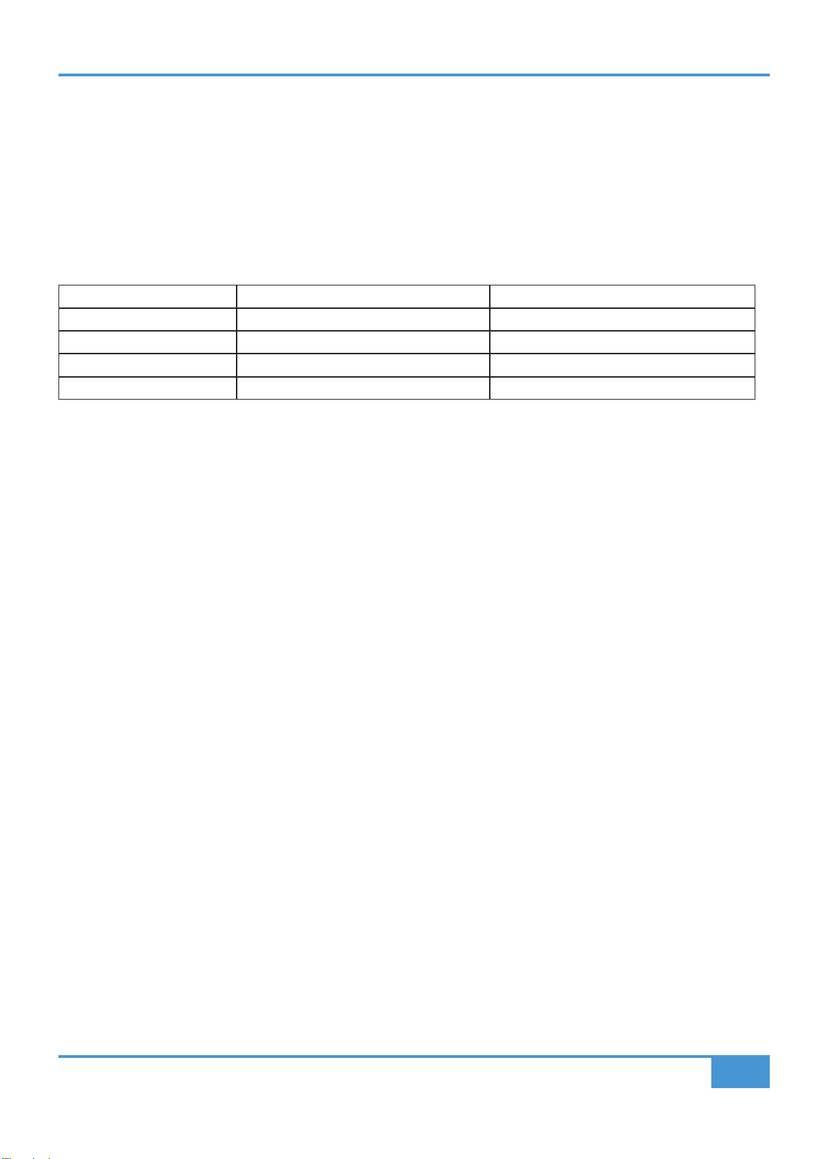
ORIGIN User Guide
Appendix A
39
Clearing ALL Routes/Crosspoints Quickly
The SHIFT/CLEAR ROUTE function also works with Range Selections. So a very quick way to clear all console routing from
all Channels to all Track Buses is to press and hold the SHIFT switch to put the console into CLEAR ROUTE mode and
simultaneously press the Track Bus 1 and Track Bus 16 switches in the centre section, this will clear all routes from Track Buses
1 to 16, i.e. all Track Bus routes/Crosspoints.
Routing LED Status Summary
A table of Track Bus and Path LED statuses.
LED Status Path ROUTED TO BUS LED Track Bus LED
Off No Path Routing No Paths Routed to Bus
On (Flashing) Path to Bus Routing Active Bus to Path Routing Active
On (Bright) Selected Path when Bus Routing Active Selected Bus when Path Routing Active
On (Dim) Path Routed to Bus Path Routed to Bus
Incremental Channel to Bus Routing
There is a shortcut to setup single Channel to single Bus routing (e.g. Channel 1 to Bus 1, Channel 2 to Bus 2 etc.) which may be
useful if working with multiple channels to a recorder attached to the Buses.
- Press and hold Channel 1 ROUTE key
- Channel 1 now selected, blinking
- Press and hold Channel 16 ROUTE key
- Channel 1 to Channel 16 now selected, all blinking
- Keep holding both switches down for 3 to 5 seconds
- Channel 1 to Channel 16 ROUTE LEDs will blink faster
- 1 to 1 incremental routing is made for the selected range.
NOTE: This incremental routing will override any existing Channel to Bus routes for the selected range.
Additionally, there is an option to change the way the incremental routes are made. The default is that the incrementally routed
Bus follows the Channel Selection, i.e. if a range of Channel 9 to Channel 16 is selected, then the Bus Routing will be Channel 9
to Bus 9, Channel 10 to Bus 10 etc. to Channel 16 to Bus 16.
This default routing can be amended using the Incremental Routing Setup option (See Page 39). With the optional setting, the
incrementally routed bus defaults to starting at Bus 1 and increments from there. i.e. using the previous example, if a range of
Channel 9 to Channel 16 is selected, then the Bus Routing will be Channel 9 to Bus 1, Channel 10 to Bus 2 etc. to Channel 16 to
Bus 8.
Latching/Momentary Key Function
The Routing keys have a similar automated latching/momentary feature to the Comms/Talkback switches, i.e. a fast press will 'latch'
the key, a longer press will make the key momentary.
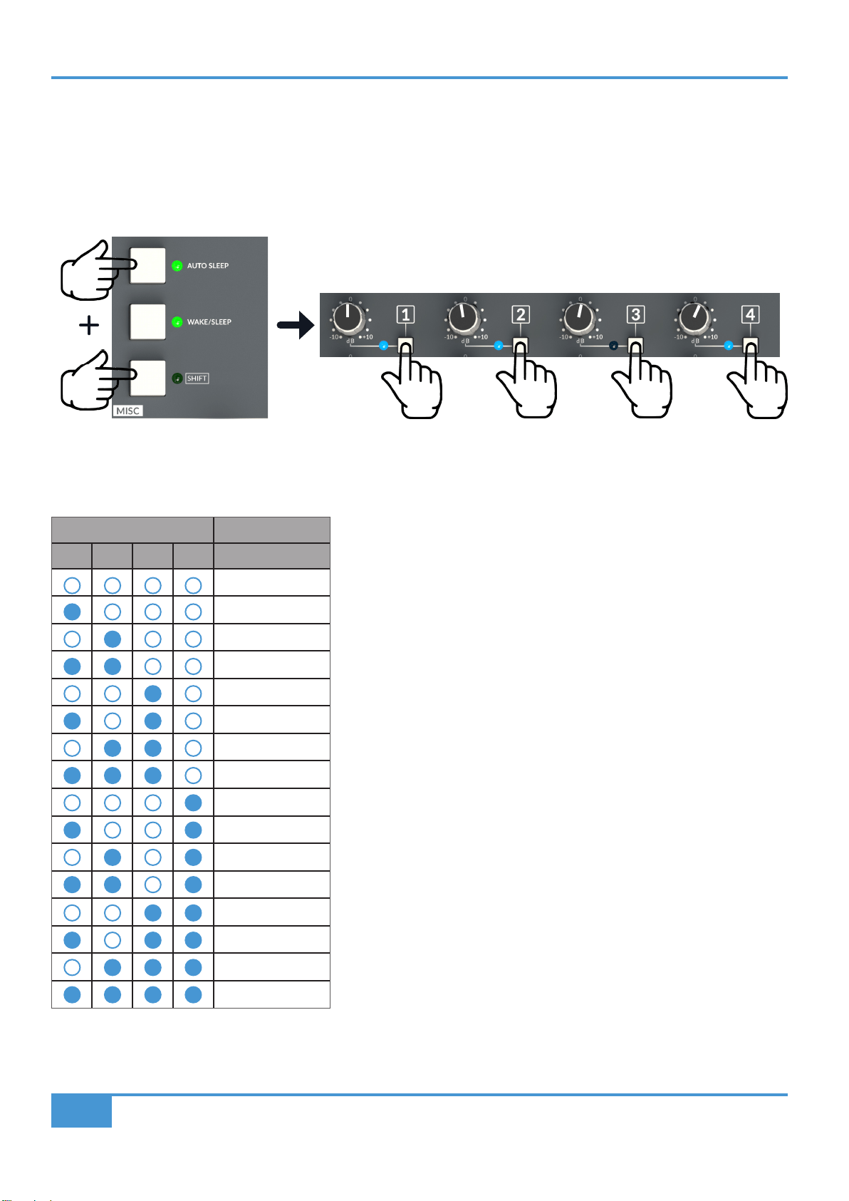
ORIGIN User Guide
Appendix B
40
Appendix B - Setup Functions
AUTO SLEEP Setup
To setup the AUTO SLEEP timeout, press and keep pressed both the SHIFT and AUTO SLEEP keys. This activates the Bus
Routing keys and LEDs to show AUTO SLEEP timeout where Bus LED's 1-4 are the console's AUTO SLEEP timeout setting and
the adjacent keys can be used to change the AUTO SLEEP timeout.
The LEDs show the timeout in binary format, with the left most LED (1) showing the least signicant digit, and the right most LED
(4) the most signicant digit. Each Binary number from 1 to 1111 is a 5 minute interval. So the AUTO SLEEP timing is represented
by the following table...
Bus LED
Time Until SLEEP
1 2 3 4 (Minutes)
15 seconds**
5
10
15
20
25
30
35
40
45
50
55
60
65
70
75
For example, the LED combination in the picture above means a time until Sleep of 55 minutes (1101)
The factory default Auto Sleep setting is 20 minutes.
** the 15 second setting may be useful to check if Auto Sleep is operating as expected.
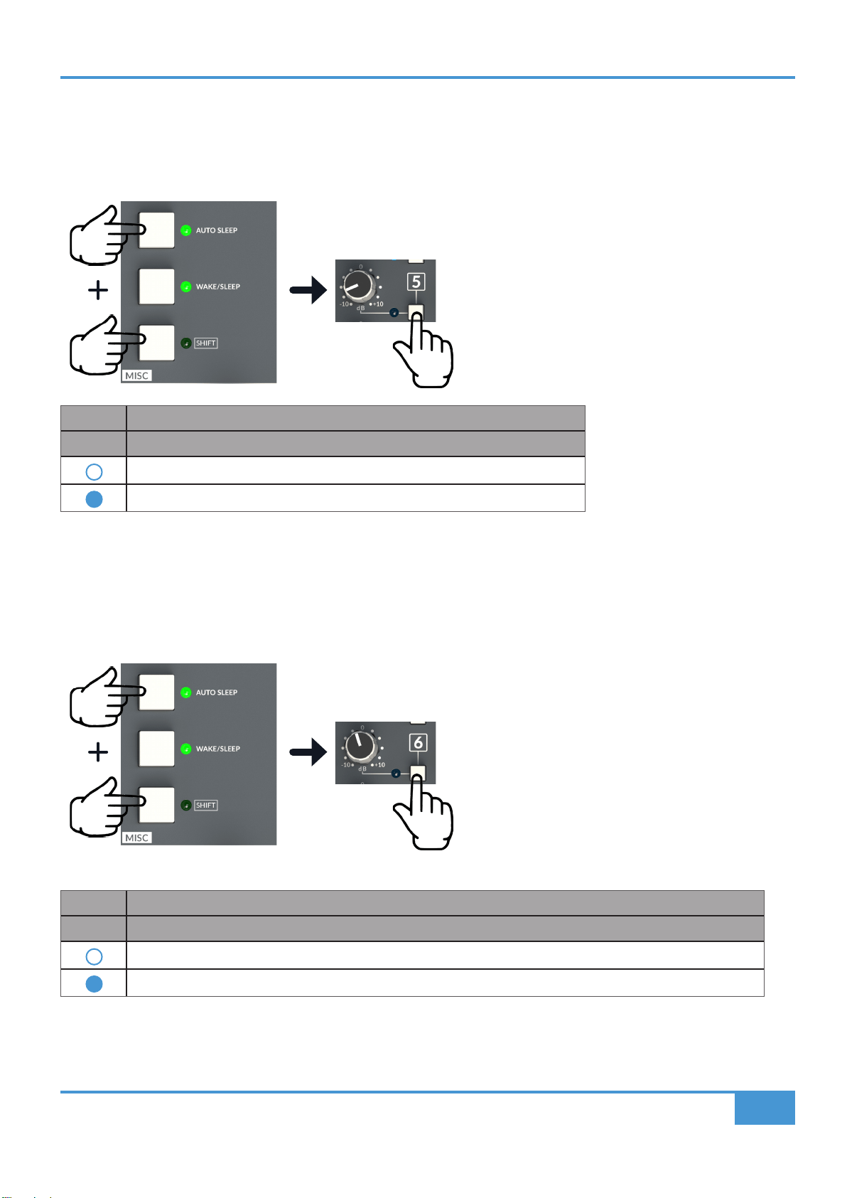
ORIGIN User Guide
Appendix B
41
ALT 3/Headphone Selection Setup
The ALT 3/Headphone Monitor Output key can be setup to intercancel with the other three Monitor Outputs (Main, ALT 1, ALT
2), rather than be an independent selection. This is another setting accessed with a simultaneous press of the SHIFT and AUTO
SLEEP keys to access the setup menu, and with the Bus 5 key/LED selecting and showing the status as per the table below.
Bus LED
5 Monitor Select Function
ALT 3/independent of Main/ALT 1/ALT 2 monitor selection. (Default)
ALT 3/intercancels with Main/ALT 1/ALT 2 monitor selection.
Automatic Incremental Routing Setup
This Setup option controls the behaviour of the Automatic Incremental Routing feature (See page 37). This is another setting
accessed with a simultaneous press of the SHIFT and AUTO SLEEP keys to access the setup menu, and with the Bus 6 key/LED
selecting and showing the status as per the table below.
Bus LED
6 Monitor Select Function
Channel number dictates the automatic bus assignment (e.g. Ch9 ->Bus 9, Ch10 -> Bus 10). (Default)
Lowest channel in selection goes to Bus 1, next channel to Bus 2, etc. (e.g. Ch9->Bus 1, Ch10-> Bus 2).
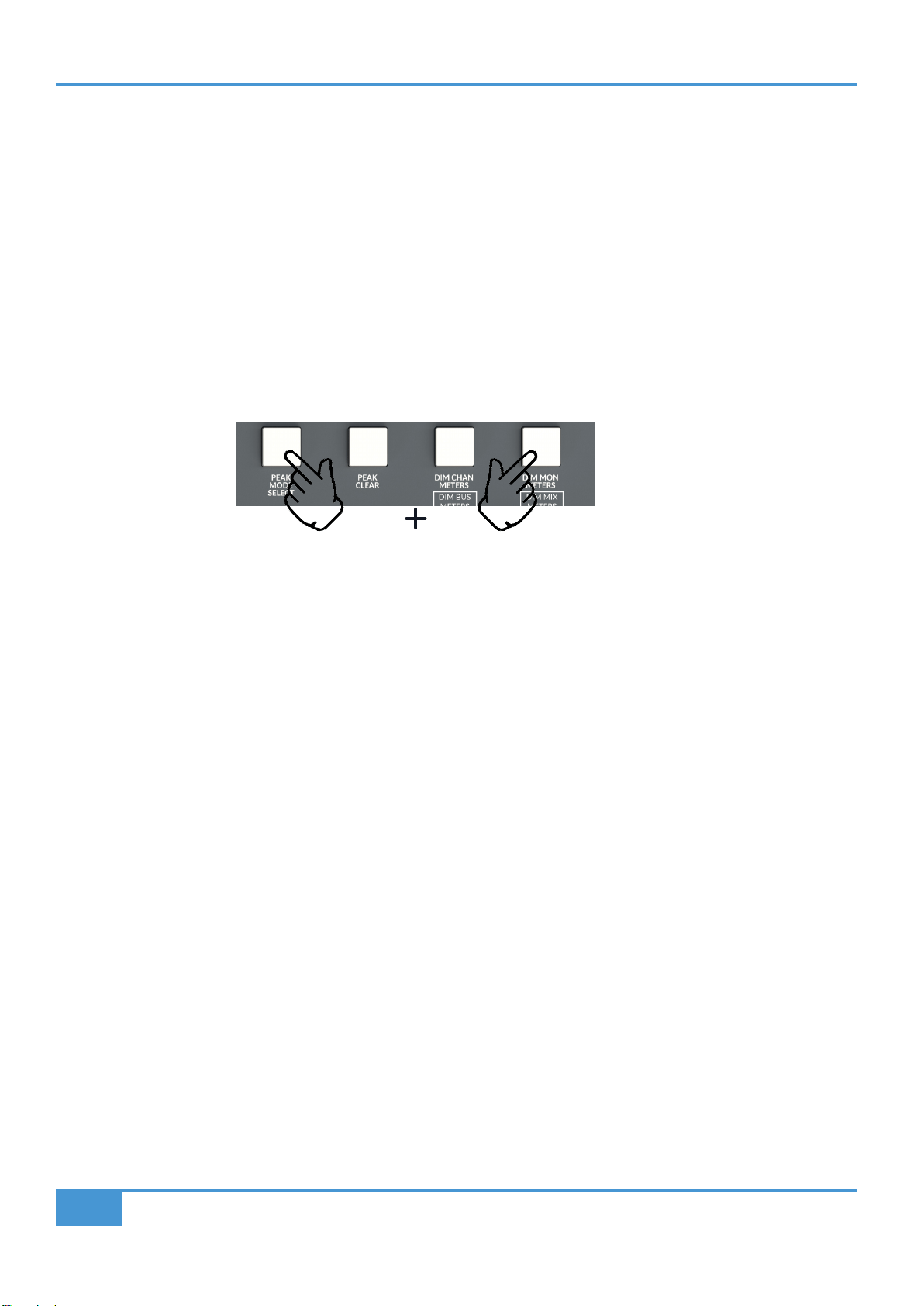
ORIGIN User Guide
Appendix B
42
Factory Setup Reset
Factory reset is provided to restore the console to its default settings and conditions.
Factory reset affects:
- Routing (all routes cleared)
- Comms settings (Monitor Dim assignments, Talk All assignments)
- Autosleep state
- Any Setting
- Monitor and Source Selection
To perform a Factory Reset:
Power up the console (either from off or from Sleep state)
Press and hold PEAK MODE SELECT + DIM MON METERS switches during and for the duration of the meter start-up sequence
which happens during power up.
Red Peak LEDs on every meter will start ashing which means that the Factory Reset has been performed.
Release the switches -> console restarts with settings back to Factory Default.
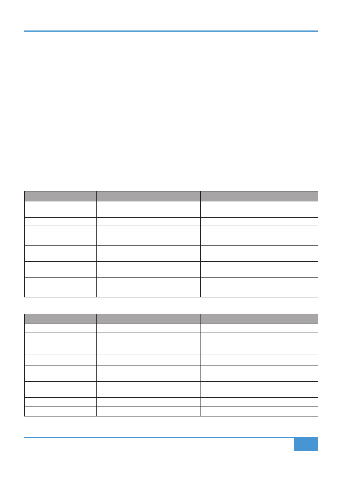
43
ORIGIN User Guide
Appendix C
Appendix C - Performance Specication
Audio Performance
Default test conditions (unless otherwise stated):
- Source impedance of Test Set: 40 Ω
- Input impedance of Test Set: 200 kΩ
- Reference frequency: 1 kHz
- Reference level: 0 dBu where 0 dBu = 0.775 V into any load
- Unless specied, all unweighted measurements are specied as 20 Hz to 20 kHz band limited RMS and are expressed in
units of dBu
- The onset of clipping (for headroom measurements) should be taken as 1% THD
- All distortion measurements are specied with a 36 dB/Octave low pass lter at 20 kHz and are expressed as a percentage
- All levels are intended balanced
Unless otherwise quoted all gures have a tolerance of ±0.5 dB or 5%.
PureDrive™ Channel Input Microphone/Line Amplier
Measurement Conditions Value
Gain **dependent on potentiometer tolerances Mic Amp Gain Variable from +5 dB to +70 dB**
Line Amp Gain Variable from -10 dB to +55 dB**
Input Impedance 1.4 kΩ
Max Input Level 1% THD Mic Amp : +21 dBu
Output Headroom >+26.5 dBu at onset of clipping
Frequency Response - 20 Hz to 20 kHz
- -3 dB high rolloff
- +0/-0.2 dB
- > 90 kHz
THD+Noise (-10 dBu applied, +30 dB gain) @ 1 kHz
(-10 dBu applied, +30 dB gain) @ 10 kHz
- <0.004% at 1 kHz (20 Hz to 20 kHz)
- <0.018% at 10 kHz (20 Hz to 40 kHz)
CMRR (-10 dBu applied, +30 dB gain) - > 57.5 dB 20 Hz to 20 kHz
Equivalent Input Noise (EIN) Mic Amp, 150 Ω termination, maximum gain - <-127.5 dBu (A-weighted)
Monitor Input Line Input Amplier
Measurement Conditions Value
Gain **dependent on potentiometer tolerances Variable from -20 dB to +20 dB**
Input Impedance 10 kΩ
Max Input Level 1% THD >+28 dBu before clipping
Output Headroom >+27.5dBu at onset of clipping
Frequency Response - 20 Hz to 20 kHz
- -3 dB high rolloff
+0/-0.03 dB
> 156 kHz
THD+Noise (-10 dBu applied, +20 dB gain) @ 1 kHz
(-10 dBu applied, +20 dB gain) @ 10 kHz
<0.0003% at 1 kHz (20 Hz to 20 kHz)
<0.0009% at 10 kHz (20 Hz to 40 kHz)
CMRR > 65 dB 20 Hz to 20 kHz
Equivalent Input Noise (EIN) 150 Ω termination, maximum gain <-104 dBu

44
ORIGIN User Guide
Appendix C
Channel Equaliser
Signal applied to line input and measured at the channel insert send. EQ switched in with EQ controls centred in shelf mode.
Measurement Conditions Value
Output Headroom >+26.5 dBu at onset of clipping
THD+Noise +20 dBu @ 1 kHz
+20 dBu @ 10 kHz
<0.003% at 20 dBu @1 kHz (lter 20 Hz to 20 kHz)
<0.003% at 20 dBu @10 kHz (lter 20 Hz to 40 kHz)
Noise <-80dBu
Overall Channel Signal Chain Specications
Signal applied to Line Input of a channel and routed to specied output by shortest path. All controls set at, out or at unity gain
as appropriate. Pan set to full left or right.
Measurement Conditions Value
Auxiliary Send, Track Bus and Main Mix
Bus Outputs
Output Headroom into 600 Ω at onset of clipping
into 10 kΩ at onset of clipping
>24 dBu
>26.5 dBu
THD+Noise +20 dBu @ 1 kHz
+20 dBu @ 10 kHz
<0.0008% @1 kHz (lter 20 Hz to 20 kHz)
<0.0008% @10 kHz (lter 20 Hz to 40 kHz)
Frequency Response
Track Buses
Main Mix Bus
Auxilliary Buses
- 20 Hz to 20 kHz
- -3 dB high rolloff
- 20 Hz to 20 kHz
- -3 dB high rolloff
- 20 Hz to 20 kHz
- -3 dB high rolloff
+0/-0.3 dB
>70 kHz
+0/-0.3 dB
>70 kHz
+0/-0.3 dB
>70 kHz
Pot centre detent accuracy: +/-1 dB, typically <0.5 dB
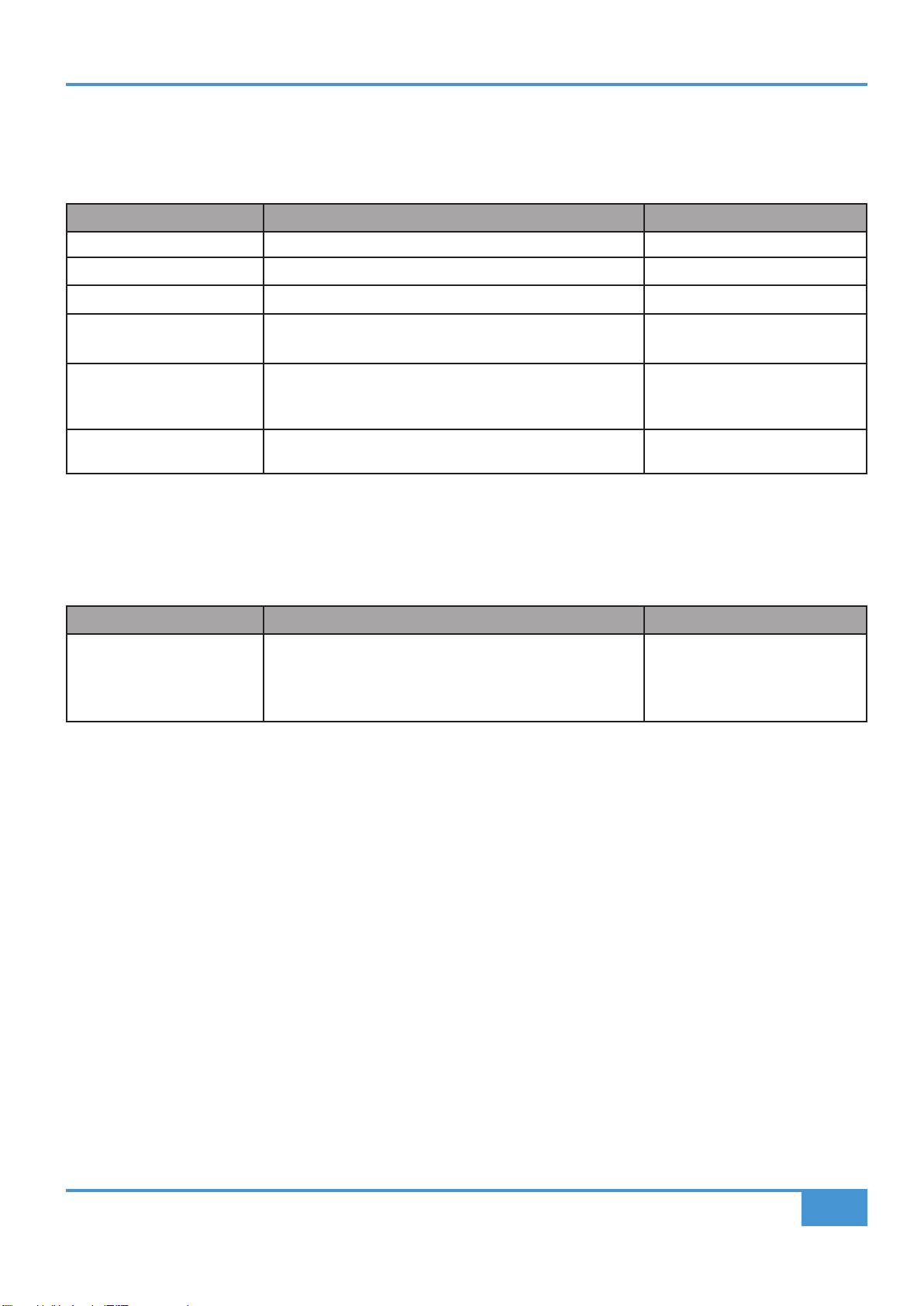
45
ORIGIN User Guide
Appendix C
Crosstalk
Signal applied to Line Input of a mono channel, and routed to specied output by shortest path. All controls set at, out or at unity
gain as appropriate. Pan set to full left or right.
Measurement Conditions Value
Channel Muting 20 Hz to 20 kHz <-100 dB
Maximum Fader Attenuation 20 Hz to 20 kHz <-89 dB
Pan pot Isolation 20 Hz to 20 kHz <-55 dB
Routing
Channel to Main Mix <-94 dB from 20 Hz to 20 kHz
Routing
Channel to Track Buses Channel routed to all buses apart from one under test
Channel not routed
<-64 dB from 20 Hz to 20 kHz
<-113 dB from 20 Hz to 20 kHz
Mic Input -50 dBu applied to Mic Input at maximum gain, measured at
Direct Output, Monitor path selected
<-95 dB
Overall Console Noise
Measured at main Mix outputs, channels routed as required with pans / balance controls centred, using Line input with termination.
All controls set at, out or at unity gain as appropriate, channel and master faders calibrated for 0dB.
Measurement Conditions Value
Line to Mix
(Pan to centre)
1 channel routed
16 channels routed
24 channels routed
32 channels routed
<-93 dBu
<-85 dBu
<-83 dBu
<-79 dBu
Environmental Requirements
Temperature range:
Operating: +1 to 30 °C (+34 to 86 °F).
Storage: -20 to 50 °C (-4 to 122 °F).
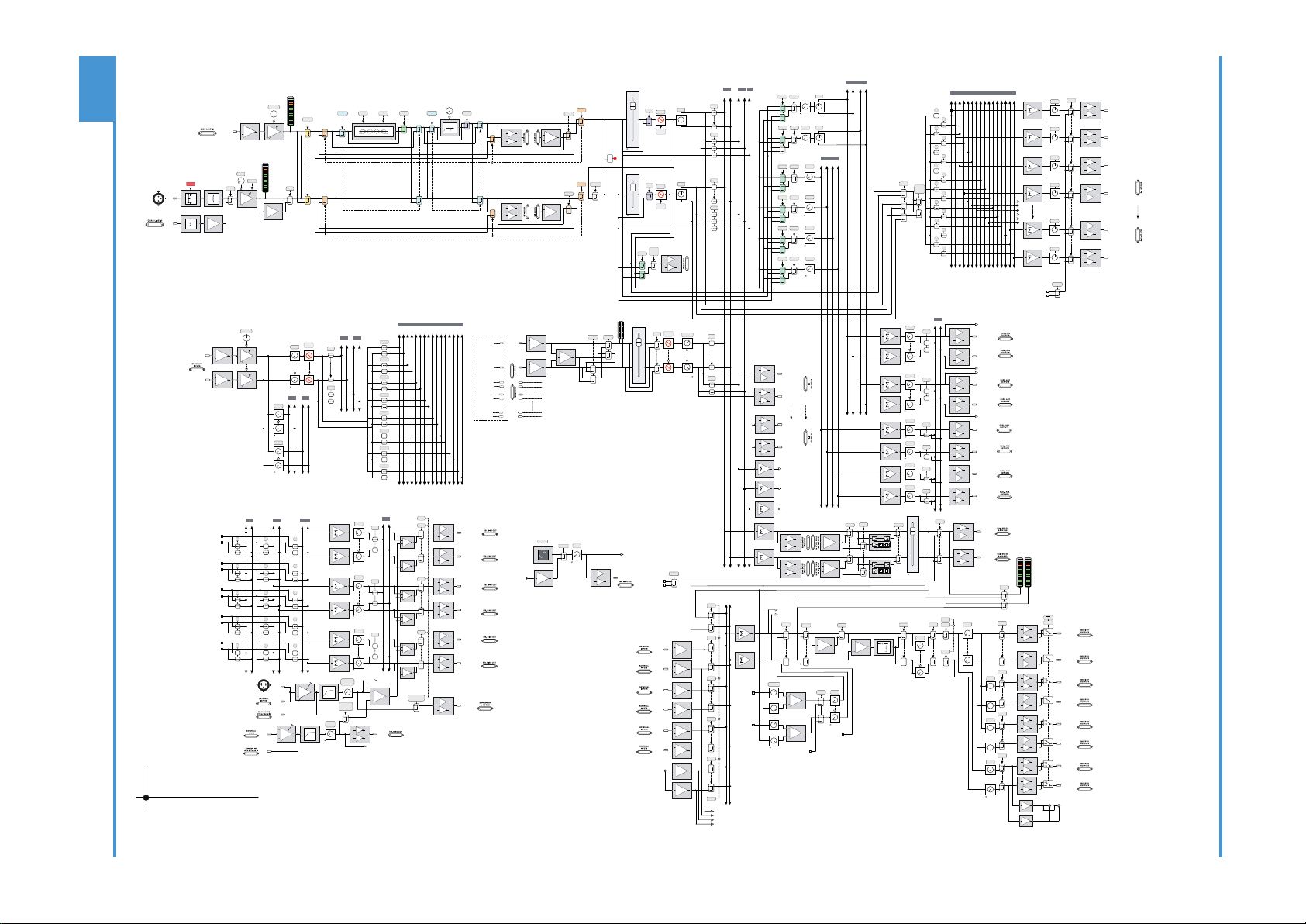
46
ORIGIN User Guide
Appendix D
Appendix D - ORIGIN Block Diagram
SWITCHED
EXT TB OUT
ON
EXT
to +10dB
GAIN
+48V
48V
MIC
+
-
MONITOR
LINE
+
-
+
-
PRE
IN
L R
1 2 3 4 5 6 7 8 9 10 11 12 13 14 15 16
+dB
TRIM
+2 to +70dB
[-12 to +55dB]
IN
FLIP
+
-
+
-
PRE
IN
FLIP
PATH
PATH
FROM LF
PAN
MIX
PAN
MIX
L R
SOLO
SOLO
CUT
SOLO
POST
SF
PAN
L R
L R
LEVEL
POST
SF
PAN
1 2 3 4
LEVEL
PRE
SF
LEVEL
PRE SF
LEVEL
PRE SF
LEVEL
PRE SF
FOLLOW
PATH
PAN
FLIP
1
2
3
4
5
6
7
8
9
10
11
12
13
14
15
16
PRE FLIP
+
-
DIRECT OUT
PATH
+
-
RETURN L
± 20dB
dB
TRIM
+
-
RETURN R
dB
L R
L R
LEVEL
LEVEL
LEVEL
MIX
AFL
1 2 3 4 5 6 7 8 9 10 11 12 13 14 15 16
1/2
3/4
5/6
7/8
9/10
11/12
13/14
15/16
CUT
FB 1
FB 2
L R
L R
to 0dB
to 0dB
to 0dB
+
-
INPUT
PATH
+
-
+
MONO L MONO R
MUTE
BALANCE
to +3dB
+3dB to
MIX
SOLO
+
-
+
-
TRIM
BUS 1 SEND OUT
BUS 2 SEND OUT
+
-
+
-
BUS 3 SEND OUT
BUS 4 SEND OUT
SUBGROUP
1L OUT
SUBGROUP
1R OUT
BUSES 1 - 16
L R
MIX AFL PFL
M
L R
MIX AFL
L R
MIX AFL
AUX 1 - 4
CUE A B
+
-
+
-
BUS 15 SEND OUT
BUS 16 SEND OUT
BUSES 1 - 16
LEVEL
L R
L R
AFL
AFL
+
-
+
-
CUE AL OUT
CUE AR OUT
to +10dB
LEVEL
AFL
+
-
+
-
CUE BL OUT
CUE BR OUT
LEVEL
AFL
+
-
AUX 1 OUT
LEVEL
AFL
+
-
AUX 2 OUT
LEVEL
AFL
+
-
AUX 3 OUT
LEVEL
AFL
+
-
AUX 4 OUT
CUE AL
CUE AR
CUE BL
CUE BR
OSC
SLATE
SLATE
L R
L R
L R
STUDIO
F/B 1
L R
F/B 2
EXT 1L
EXT 1R
EXT 4L
EXT 4R
C/ROOM L
C/ROOM R
CUE AL
CUE AR
CUE BL
CUE BR
to +10dB
LEVEL
L R
L R
AFL
AFL
+
-
+
-
F/BACK AL OUT
EXT 1L
EXT 1R
to +10dB
LEVEL
AFL
+
-
+
-
to +10dB
LEVEL
AFL
+
-
+
-
STUDIO L OUT
STUDIO R OUT
+
TALKBACK MIC
FRONT PANEL TRIM
(+40 to +65dB)
dB
+
-
TALKBACK
MIC
INPUT
LISTEN
MIC
INPUT
+
-
SEND
LISTEN TO
TALKBACK
LISTEN
OUT
LISTEN
(Feed To Monitor Section)
+
+
TALK
F/BACK AR OUT
F/BACK BL OUT
F/BACK BR OUT
+
+
TALK
+
+
TALK
ALL
to 0dB
TALKBACK
LEVEL
to 0dB
SLATE
LISTEN
LEVEL
to 0dB
+
-
+
-
IN
+
-
+
-
BUS COMP
+
-
+
-
MIX L OUT
MIX R OUT
AFL L
AFL R
PFL
+
-
MAIN L OUT
+
-
MAIN R OUT
ALT 1
+
-
ALT 1L OUT
+
-
ALT 1R OUT
ALT 2
+
-
ALT 2L OUT
+
-
ALT 2R OUT
ALT 3
+
-
ALT 3L OUT
+
-
ALT 3R OUT
MAIN
CUT L
CUT R
-1
POL
3dB
MONO
+
LISTEN
POWER
CUT
P/AFL
LISTEN
iJACK
+
-
L R
+
-
+
-
+
-
+
-
EXT 1
+
-
EXT 1L
EXT 1R
EXT 4
EXT 2
EXT 3
EXT 2L
EXT 2R
EXT 3L
EXT 3R
10K
1.5K
to 0dB
LEVEL
CUT
DIM
+dB
+dB
MIX
SUM
PFL
PFL
0 to -40dB
LEVEL
to 0dB
LEVEL
BALANCE
to 0dB
0dB to
AFL L
AFL R
+
+
TRIM
± 20dB
TRIM
± 20dB
to 0dB
LEVEL
Headphone Jacks (under armrest/front buffer)
EXT OSC
+dB
440Hz
to +10dB
LEVEL
TRIM
TRIM
TRIM
TRIM
TRIM
to 0dB
to 0dB
to 0dB
to 0dB
to +10dB
to 0dB
±20dB
±20dB
±20dB
±20dB
±20dB
±20dB
OSC
Channel Strip (x16 or x32)
Stereo Return (x4)
Stereo Groups (x8)
Oscillator
Communications (Foldback and Studio)
Control Room Monitoring
Stereo Cues
Aux Sends
Mix Bus
Track Buses (x16)
AFL/PFL
IN FRONT
SOLO
LINE
F/B 1
F/B 2
MON
+
-
OSC OUT
IN
S/C
VCA
INSERT
-1
ø
FLIP
PATH
IN
0dB
0dB
0dB
HPF
EQ
VCA
S/C
VCA
VCA
KEY
INSERT INSERT COMP
to +10dB
to +10dB
to +10dB
to +10dB
BUS SEND 1
BUS SEND 2
BUS SEND 3
BUS SEND 4
BUS SEND 5
BUS SEND 6
BUS SEND 15
BUS SEND 16
C/ROOM L
C/ROOM R
EXT 1L
EXT 1R
EXT 4L
EXT 4R
DRIVE
-10dB
± 20dB
BELL
BELL
LF HF
Hz
CUT
to 0dB
to +10dB
to 0dB
+
-
EXT TB OUT
TONE
SLATE
TONE
SLATE
OSC
SLATE
SLATE
LF
INSERT
SF
INSERT
OVERLOAD
(-3dB below
Path Clip)
≥1
LARGE
FADER
SMALL
FADER
CUT
SOLO
CUT
BUS SENDS
VIA DB-25 LINK
OR HALF NORMALLED
PATCH ROW
+
-
+
-
SUBGROUP
8L OUT
SUBGROUP
8R OUT
LISTEN
FRONT PANEL TRIM
+40 to +65dB
TALKBACK
COMPRESSOR
LISTEN
COMPRESSOR
TALKBACK
LINE
INPUT
LISTEN
LINE
INPUT
FRONT
PANEL
XLR
dB
+
-
+
-
+
-
O R I G I N
Drawn: NF, CJ
Revison: 2.00
Date: 21.09.2022
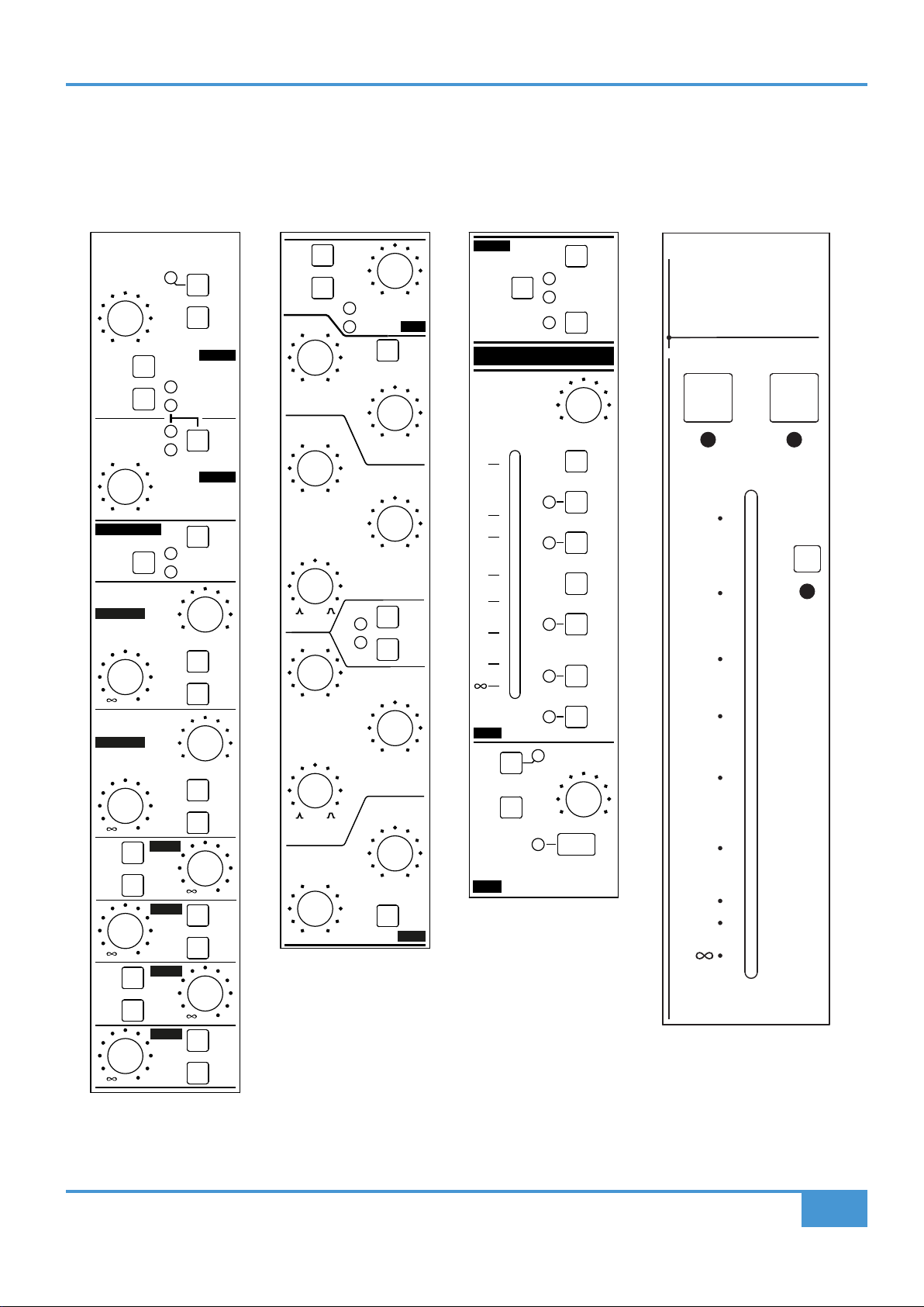
47
ORIGIN User Guide
Appendix E
Appendix E - Recall Sheets
Channel Recall Sheet
0
10
15
20
30
40
50
10
0 dB
SOLO CUT
LF
SF
INS
IN
INS
PRE
0dB
LF TO
MIX
ROUTE
30
20
10
5
0
5
10
BUSES
FOLLOW
PATH PAN
PATH
FLIP
ROUTED
TO BUS
OVERLOAD
SF PAN
RL
SF
FROM
LF
SF
TO
MIX
SOLO
CUT
SF
LF PAN
RL
LF
INS
IN
INS
PRE
LF
LF
SF
SF
LF
SF
SF
PRE
PRE
48 V
PRE
GAIN
TRIM
POST
SF
PAN
PAN
POST
SF
PRE
DRIVE
ST CUE A
ST CUE B
AUX1
AUX3
SF
PRE
SF
SF
PRE
AUX2
AUX4
0
/
+20-20
0
dB
dB
+70+2
(+55)(-12)
CHAN
LINE
PATH
FLIP
MON
PATH
FLIP
DIRECT OUT
RL
RL
LF
SF
IN
BELL
BELL
IN
EQ
+
-
0
dB
+-
0
dB
+
-
0
dB
+-
0
dB
PATH
FLIP
40 010
Hz
HPF
HF
161.5
kHz
105
HMF
Q
7.6
kHz
4.51.5
PATH
FLIP
LF
SF
Q
2.5.2
kHz
1.5.8
LMF
LF
45030
Hz
100 300
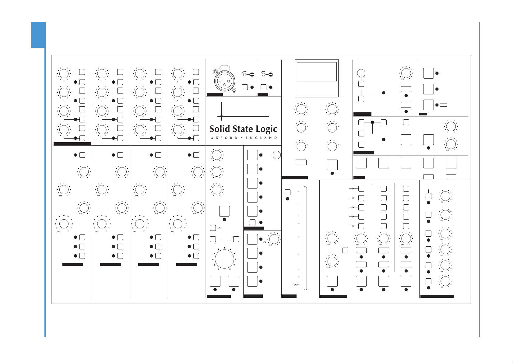
48
ORIGIN User Guide
Appendix E
TALKBACK
BUS COMPRESSOR
METERS
SOLO MASTER
OSCILLATOR
AFL
STEREO
CUE A
STEREO
CUE B
AUX 1
AUX 2
AUX 3
AUX 4
INPUT
TRIM
TO F/BACK A
TO F/BACK B
ALT MON 1
ALT MON 2
L
R
MUTE
EXTERNAL 1
EXTERNAL 2
EXTERNAL 3
PEAK
CLEAR
SOLO
CLEAR
IN FRONT
BALANCE
SOLO
LEVEL
SF SIP
PFL
SOLO
LINK
LF SIP
SOLO
ACTIVE
OSC
LEVEL
ON
AFL AFL AFL
LISTEN
LEVEL
EXT 1
CONTROL
ROOM
STEREO
CUE A
STEREO
CUE B
STUDIO
MON SOURCE
DIM LEVEL
MONO
SUM
COMMUNICATIONS
MON SELECT
MONITOR LEVELS
DIM
CUT
TALK TALK TALK
LISTEN
SLATE
SUBGRP SIP
MONITOR
LEVEL
ROUTED
TO BUS
IN
MAIN
8
4
7
3
6
2
9
5
1
10
5
43
2
1.5 300
185
12060
30
OFF
AUTO
1.6
.8.4
.2
.1
30
10
31
.3
.1
RATIO
ATTACK - ms RELEASE - s
THRESHOLD - dB
SIDECHAIN
HPF - Hz
STEREO RETURN 2STEREO RETURN 1 STEREO RETURN 3 STEREO RETURN 4
L 0
O R I G I N
LISTEN
TRIM TRIM
MIX
AFL
0
+10
0
dB
+10
0
dB
+10
0
dB
+10
0
dB
+10
0
dB
+10
0
dB
0
dB
+10
0
dB
+10
0
dB
+10
0 0 0 0
0 0 0 0
+20-20
0
dB
+20-20
0
dB
+20-20
0
dB
INPUT
TRIM
TO F/BACK A
TO F/BACK B
ROUTED
TO BUS
+20-20
0
dB
INPUT
TRIM
TO F/BACK A
TO F/BACK B
ROUTED
TO BUS
+20-20
0
dB
INPUT
TRIM
TO F/BACK A
TO F/BACK B
ROUTED
TO BUS
+20-20
0
dB
-3-30
dB
+ +
dB
0
0
0
AUTO SLEEP
WAKE/SLEEP
MAKEUP - dB
-20 +20 +200
10
+10-10
0
dB
+10-10
0
dB
+10-10
0
dB
+10-10
0
dB
+10-10
0
dB
+10-10
0
dB
+10-10
0
dB
+10-10
0
dB
+10-10
0
dB
+10-10
0
dB
+10-10
0
dB
+10-10
0
dB
+10-10
0
dB
+10-10
0
dB
+10-10
0
dB
+10-10
0
dB
BUS MASTERS TRIM AND ROUTING
16
12
15
11
14
10
13
TALKBACK
INSERT
RETURN
JACK IN
EXT IN
IN
400 Hz
ON
+10
MISC
RED LIGHT
PEAK
MODE
SELECT
DIM CHAN
METERS
DIM MON
METERS
MIX METER
FOLLOW MON
SOURCE
TO BUSES
JACK IN
SWITCHED
EXT TB OUT
SEND
LISTEN TO
TALKBACK
TALKBACK
LEVEL
FOLDBACK
A
FOLDBACK
B
MIX BUS
ALT 3
MIX
ALT MON 1
ALT MON 2
ROUTE ROUTE ROUTE ROUTE
LEVEL
MIX
AFL
CUT
MIX
AFL
CUT
MIX
AFL
CUT
MIX
AFL
CUT
LEVEL LEVEL LEVEL
dB
0
dB
0
dB
0
dB
0
110
INSERT
0
20
30
40
50
15
5
48 V 48 V
TO MIX
CUES AND AUX MASTERS
SHIFT
/ CLEAR ROUTE
DIM BUS
METERS
DIM MIX
METERS
TALK ALL
Master Section Recall Sheet
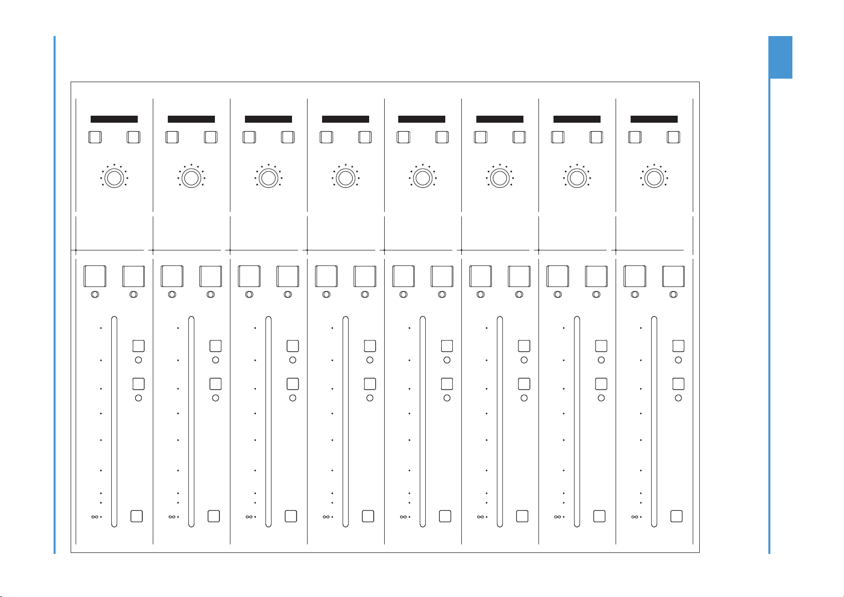
49
ORIGIN User Guide
Appendix E
GRP TO
MIX
GRP TO
MIX
GRP TO
MIX
GRP TO
MIX
GRP TO
MIX
GRP TO
MIX
GRP TO
MIX
GRP TO
MIX
0
10
15
20
30
40
50
10
0
10
15
20
30
40
50
10
0
10
15
20
30
40
50
10
0
10
15
20
30
40
50
10
0
10
15
20
30
40
50
10
0
10
15
20
30
40
50
10
0
10
15
20
30
40
50
10
0
10
15
20
30
40
50
10
MONO
L
MONO
R
BALANCE
SOLO CUT
0 dB
MONO
L
MONO
R
BALANCE
SOLO CUT
0 dB
MONO
L
MONO
R
BALANCE
SOLO CUT
0 dB
MONO
L
MONO
R
BALANCE
SOLO CUT
0 dB
MONO
L
MONO
R
BALANCE
SOLO CUT
0 dB
MONO
L
MONO
R
BALANCE
SOLO CUT
0 dB
MONO
L
MONO
R
BALANCE
SOLO CUT
0 dB
MONO
L
MONO
R
BALANCE
SOLO CUT
0 dB
A
B
C D E F G
H
ST GRP 15-16ST GRP 13-14ST GRP 11-12ST GRP 9-10ST GRP 7-8ST GRP 5-6ST GRP 3-4ST GRP 1-2
RL RL RL RL RL RL RL RL
Stereo Group Recall Sheet
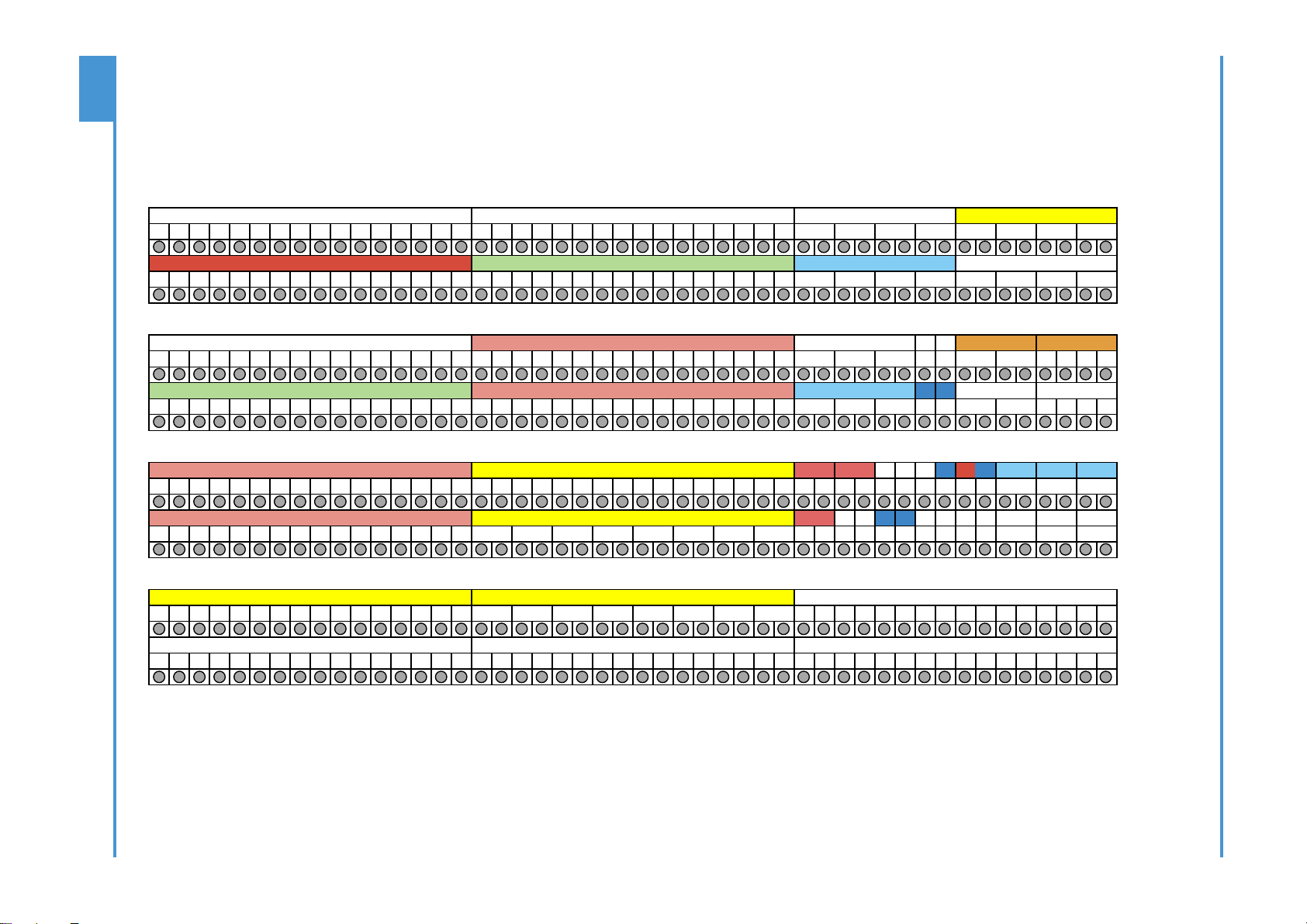
50
ORIGIN User Guide
Appendix F
1 2 3 4 5 6 7 8 9 10 11 12 13 14 15 16 17 18 19 20 21 22 23 24 25 26 27 28 29 30 31 32 33 34 35 36 37 38 39 40 41 42 43 44 45 46 47 48
1 2 3 4 5 6 7 8 9 10 11 12 13 14 15 16 1 2 3 4 5 6 7 8 9 10 11 12 13 14 15 16
A
1 2 3 4 5 6 7 8 9 10 11 12 13 14 15 16 1 2 3 4 5 6 7 8 9 10 11 12 13 14 15 16
B
1 2 3 4 5 6 7 8 9 10 11 12 13 14 15 16 1 2 3 4 5 6 7 8 9 10 11 12 13 14 15 16 1 2 3 4
C
Tb Lm
1 2 3 4 5 6 7 8 9 10 11 12 13 14 15 16 1 2 3 4 5 6 7 8 9 10 11 12 13 14 15 16 In In 1 2 3 4
D
Tb
Osc
Lm
1 2 3 4 5 6 7 8 9 10 11 12 13 14 15 16 1 2 3 4 5 6 7 8 9 10 11 12 13 14 15 16 L R L R op op op
E
TbL
LmL
1 2 3 4 5 6 7 8 9 10 11 12 13 14 15 16 L R In In
F
1 2 3 4 5 6 7 8 9 10 11 12 13 14 15 16 1 2 3 4 5 6 7 8 9 10 11 12 13 14 15 16
G
1 2 3 4 5 6 7 8 9 10 11 12 13 14 15 16 1 2 3 4 5 6 7 8 9 10 11 12 13 14 15 16 1 2 3 4 5 6 7 8 9 10 11 12 13 14 15 16
H
Coloured Idents are DB-25 (XLR for Mics) to/from Console Connector Panel(s)
L-S-R
Dist 1
Dist 2
SLS
L-1-R
L-2-R
L-S-R
DAW Inputs
Direct Outputs
M Snd
L-1-R
L-2-R
L-H-R
SF Insert Sends
Bus Outputs
MIX OP
M rt n
L-A-R
L-B-R
L-C-R
L-D-R
L-E-R
L-F-R
L-G-R
SF Insert Returns
Stereo Group Inputs
L-3-R
Line Tielines
LF Insert Sends
LF Insert Sends
Channel Line Inputs
Mic Tielines
DAW Outputs
Channel Mic Inputs
Monitor Inputs
L-3-R
FX Out
Monitor Outputs
L-1-R
L-2-R
L-3-R
User Option
User Option
L-A-R
L-B-R
L-1-R
L-2-R
L-3-R
L-4-R
L-1-R
L-2-R
FB 1
FB 2
Studio
L-4-R
L-1-R
L-2-R
L-F-R
L-G-R
L-H-R
Stereo Group Outputs
User Option
L-A-R
L-B-R
L-C-R
L-D-R
L-E-R
L-4-R
L-M-R
L-a1-R
L-a2-R
L-a3-R
Stereo Return Inputs
Amp I nput s
External Feeds
Cue Bus OP
Aux Bus OP
External IPs
Cue A
FX I n
L-1-R
L-2-R
L-3-R
L-1-R
L-2-R
Appendix F - Suggested Patchbay Layouts
Origin 16
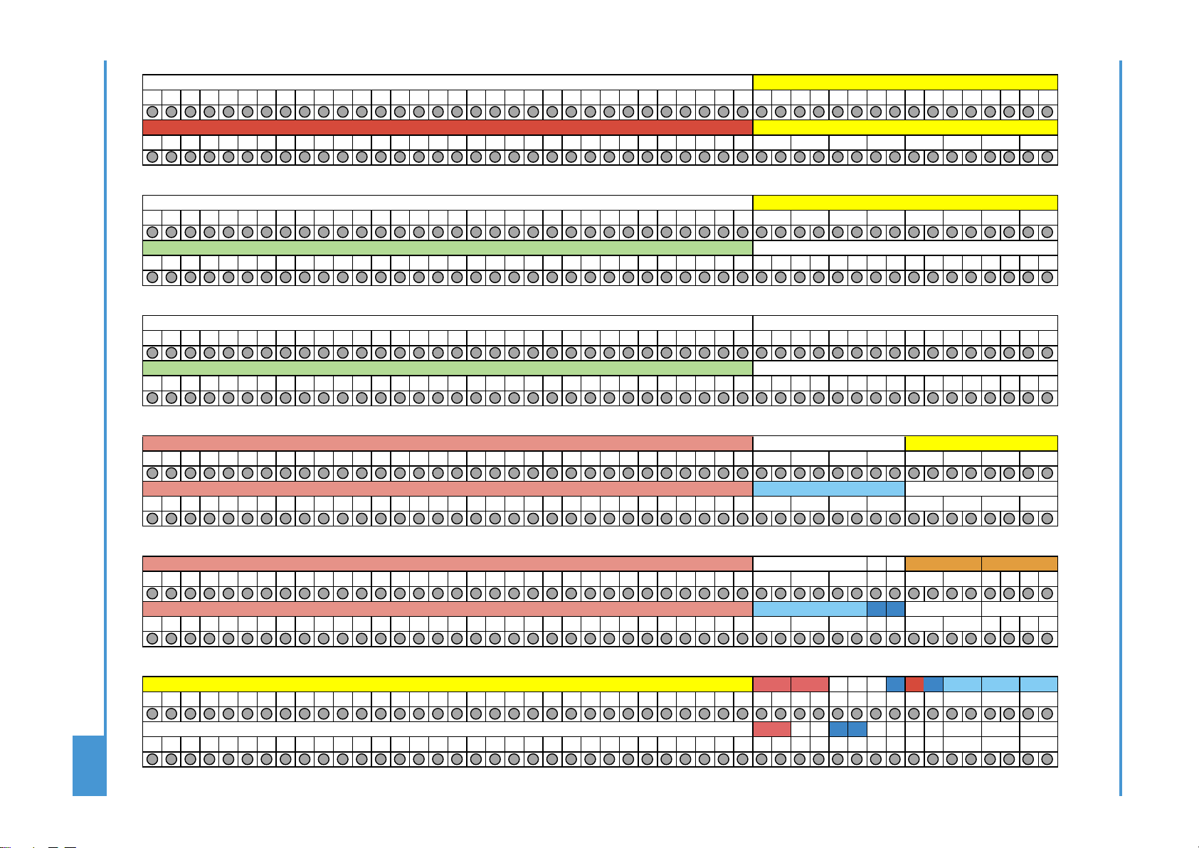
51
ORIGIN User Guide
Appendix F
1 2 3 4 5 6 7 8 9 10 11 12 13 14 15 16 17 18 19 20 21 22 23 24 25 26 27 28 29 30 31 32 33 34 35 36 37 38 39 40 41 42 43 44 45 46 47 48
1 2 3 4 5 6 7 8 9 10 11 12 13 14 15 16 17 18 19 20 21 22 23 24 25 26 27 28 29 30 31 32 1 2 3 4 5 6 7 8 9 10 11 12 13 14 15 16
A
1 2 3 4 5 6 7 8 9 10 11 12 13 14 15 16 17 18 19 20 21 22 23 24 25 26 27 28 29 30 31 32
B
1 2 3 4 5 6 7 8 9 10 11 12 13 14 15 16 17 18 19 20 21 22 23 24 25 26 27 28 29 30 31 32
C
1 2 3 4 5 6 7 8 9 10 11 12 13 14 15 16 17 18 19 20 21 22 23 24 25 26 27 28 29 30 31 32 1 2 3 4 5 6 7 8 9 10 11 12 13 14 15 16
D
1 2 3 4 5 6 7 8 9 10 11 12 13 14 15 16 17 18 19 20 21 22 23 24 25 26 27 28 29 30 31 32 1 2 3 4 5 6 7 8 9 10 11 12 13 14 15 16
E
1 2 3 4 5 6 7 8 9 10 11 12 13 14 15 16 17 18 19 20 21 22 23 24 25 26 27 28 29 30 31 32 1 2 3 4 5 6 7 8 9 10 11 12 13 14 15 16
F
1 2 3 4 5 6 7 8 9 10 11 12 13 14 15 16 17 18 19 20 21 22 23 24 25 26 27 28 29 30 31 32
G
1 2 3 4 5 6 7 8 9 10 11 12 13 14 15 16 17 18 19 20 21 22 23 24 25 26 27 28 29 30 31 32
H
1 2 3 4 5 6 7 8 9 10 11 12 13 14 15 16 17 18 19 20 21 22 23 24 25 26 27 28 29 30 31 32 1 2 3 4
I
Tb Lm
1 2 3 4 5 6 7 8 9 10 11 12 13 14 15 16 17 18 19 20 21 22 23 24 25 26 27 28 29 30 31 32 In
In 1 2 3 4
J
Tb
Osc
Lm
1 2 3 4 5 6 7 8 9 10 11 12 13 14 15 16 17 18 19 20 21 22 23 24 25 26 27 28 29 30 31 32 L R L R op op op
K
TbL
LmL
1 2 3 4 5 6 7 8 9 10 11 12 13 14 15 16 17 18 19 20 21 22 23 24 25 26 27 28 29 30 31 32 L R In In
L
Coloured Idents are DB-25 (XLR for Mics) to/from Console Connector Panel(s)
L-B-R
L-C-R
L-D-R
L-E-R
L-F-R
L-2-R
Mic Tielines
Bus Outputs
Channel Mic Inputs
Stereo Group Inputs
L-A-R
L-B-R
L-C-R
L-D-R
L-E-R
L-F-R
L-G-R
L-H-R
L-A-R
L-G-R
L-H-R
SF Insert Returns
M rt n
Dist 1
L-2-R
L-1-R
SF Insert Sends
Cue Bus OP
External IPs
L-3-R
External Feeds
DAW Inputs
Direct Outputs
L-A-R
L-2-R
L-3-R
L-1-R
DAW Outputs
Line Tielines
Channel Line Inputs
L-1-R
L-1-R
LF Insert Sends
LF Insert Returns
Monitor Inputs
L-2-R
Stereo Return Inputs
FX Out
L-4-R
L-3-R
User Option
User Option
L-1-R
Stereo Group Outputs
Studio
FB 2
M Snd
MIX OP
L-2-R
L-3-R
L-a1-R
Monitor Outputs
L-a3-R
Amp I nput s
L-4-R
L-M-R
L-a2-R
Aux Bus OP
User Option
L-2-R
L-S-R
Dist 2
SLS
L-1-R
L-4-R
L-S-R
L-2-R
Cue A
L-2-R
L-1-R
FB 1
L-1-R
FX I n
L-3-R
L-B-R
Origin 32

52
ORIGIN User Guide
Notes
Notes

53
ORIGIN User Guide
Notes
Notes