Heavy Duty Diagnostic Tool
HD V3.0
User Manual


Heavy Duty & OBDII Diagnostic Tool HD V3.0
I
EN
Disclaimer
All information, illustrations, and specifications contained in this manual
are based on the latest information available at the time of publication. The
right is reserved to make change at any time without notice.
Safety Precautions and Warnings
To prevent personal injury or damage to vehicles and/or the HD V3.0,
please read this user‟s manual first carefully and observe the following safety
precautions at a minimum whenever working on a vehicle:
Always perform automotive testing in a safe environment.
Do not attempt to operate of observe the tool while driving a vehicle.
Operating or observing the tool will cause driver distraction and could
cause a fatal accident.
Wear safety eye protection that meets ANSI standards.
Keep clothing, hair, hands, tools, test equipment, etc. away from all
moving or hot engine parts.
Operate the vehicle in a well-ventilated work area: Exhaust gases are
poisonous.
Put blocks in front of the drive wheels and never leave the vehicle
unattended while running tests.
Use extreme caution when working around the ignition coil, distributor
cab, ignition wires and spark plugs. These components create
hazardous voltages when the engine is running.
Put the transmission in P(for A/T) or N(for M/T) and make sure the
parking brake is engaged.
Keep a fire extinguisher suitable for gasoline/ chemical/ electrical fires
nearby.
Don‟t connect or disconnect any test equipment while the ignition is on or
the engine is running.
Keep the HD V3.0 dry, clean, free from oil/ water or grease. Use a mild
detergent on a clean cloth to clean the outside of the HD V3.0, when
necessary.

Heavy Duty & OBDII Diagnostic Tool HD V3.0
II
Table of contents
1 Introduction ............................................................................................... 1
2 General Information .................................................................................. 1
2.1 On-Board Diagnostics (OBD) II ......................................................... 1
2.2 Diagnostic Trouble Codes (DTCs) ..................................................... 2
2.2.1 OBDII DTC ................................................................................. 2
2.2.2 DTCs for J1587 /J1708 and J1939 ............................................. 3
2 .3 J1708/J1587/J1939 .......................................................................... 4
2.4 OBD Definitions ................................................................................. 5
3 Product Descriptions ................................................................................. 6
3.1 Outline of HD V3.0 ............................................................................. 7
3.2 Specifications .................................................................................... 8
3.3 Accsessories ..................................................................................... 9
3.4 Power supply ..................................................................................... 9
4 Connections & General Operations......................................................... 11
4.1 Connections .................................................................................... 11
4.2 Battery ............................................................................................. 12
4.3 DTC Library ..................................................................................... 13
4.4 Settings ........................................................................................... 13
4.5 About ............................................................................................... 14
5 Diagnose ................................................................................................ 14
5.1 Truck OBD Diagnosing ..................................................................... 16
5.1.1 Read DTC ................................................................................. 17
5.1.2 Clear DTC ................................................................................ 18
5.1.3 Live Data .................................................................................. 18
5.2 Car OBDII Diagnosing ..................................................................... 19
5.2.1 Read Codes .............................................................................. 19
5.2.2 Erase Codes ............................................................................ 20
5.2.3 I/M Readiness .......................................................................... 21
5.2.4 Live Data ................................................................................... 21
5.2.5 View Freeze Frame ................................................................... 21
5.2.6 Oxygen sensor test ................................................................... 21
5.2.7 On-board monitor test ............................................................... 22
6 How to Upgrade HD V3.0 ....................................................................... 22
6.1 Upgrading flowchart ......................................................................... 22
6.2 User registration .............................................................................. 23
6.3 Upgrading:......................................................................................... 24
7 FAQ ........................................................................................................ 24

Heavy Duty & OBDII Diagnostic Tool HD V3.0
1
EN
1 Introduction
The HD V3.0 is specially developed by iCarsoft for heavy duty vehicles,
which support all 10 modes of OBDII test (EVAP, 02 Sensor, I/M Readiness,
MIL Status, VIN info, and On – board monitors testing etc.) for a complete
diagnosis and enables users to read DTCs, clear DTCs and view the
datastream with a live color graphing. It covers a wide range of vehicles since
it offers multiple data bus protocols, such as J1587 and J1939. It can be
connected to PC through the USB cable or upgrade to keep updated with the
latest software version.
Notice: HD V3.0 may automatically reset while being disturbed by strong
static electricity. THIS IS A NORMAL REACTION.
2 General Information
2.1 On-Board Diagnostics (OBD) II
The first generation of On-Board Diagnostics (called OBD I) was
developed by the California Air Resources Board (ARB) and implemented in
1988 to monitor some of the emission control components on vehicles. As
technology evolved and the desire to improve the On-Board Diagnostic
system increased, a new generation of On-Board Diagnostic system was
developed. This second generation of On-Board Diagnostic regulations is
called “OBD II”.
The ODB II system is designed to monitor emission control systems and
key engine components by performing either continuous of periodic tests of
specific components and vehicle conditions. When a problem is detected, the
OBD II system turns on a warning lamp (MIL) on the vehicle instrument panel
to alert the driver typically by the phrase of “Check Engine” or “Service
Engine Soon”. The system will also store important information about the
detected malfunction so that a technician can accurately find and fix the
problem. Here below follow three pieces of such valuable information:
1. Whether the Malfunction Indicator Light (MIL) is commanded „on‟ or
„off‟;

Heavy Duty & OBDII Diagnostic Tool HD V3.0
2
2. Which, if any, Diagnostic Trouble Codes (DTCs) are stored;
3. Readiness Monitor status.
2.2 Diagnostic Trouble Codes (DTCs)
Diagnostic Trouble Codes (DTCs) are codes that are stored by the
on-board computer diagnostic system in response to a problem found in the
vehicle. These codes identify a particular problem area and the intended to
provide you with a guide as to where a fault might be occurring within a
vehicle.
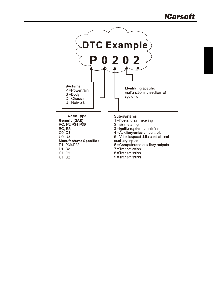
2.2.1 OBDII DTC
OBD II Diagnostic Trouble Codes consist of a five-digit alphanumeric
code. The first character, a letter, identifies which control system sets the
code. The second character, a number, 0-3; other three characters, a hex
character, 0-9 or A-F provide additional information on where the DTC
originated and the operating conditions that caused it to set. Here below is an
example to illustrate the structure of the digits:
Heavy Duty & OBDII Diagnostic Tool HD V3.0
3
EN
Figure 2-1
2.2.2 DTCs for J1587 /J1708 and J1939
This section explains the basic elements of fault codes for J1587 / J1708
and J1939 data bus protocols, how to view these codes on HD V3.0, and
what they mean. Each fault code on HD V3.0 contain three distinct pieces of
information, as described below.
J1587 /J1708 fault codes consist of the following, in this order:
Subsystem Identifier (SID) – Indicates what function on the ECU has
failed.
Failure Mode Indicator (FMI) – Indicates in what way the function
failed.
Occurrence (OC) – Indicates the occurrence times of fault codes.
J1939 fault codes consist of the following, in this order:
Suspect Parameter Number (SPN) – Indicates what function on the

Heavy Duty & OBDII Diagnostic Tool HD V3.0
4
ECU has failed.
Failure Mode Indicator (FMI) – Indicates in what way the function
failed.
Occurrence (OC) – Indicates the occurrence times of fault codes.
2 .3 J1708/J1587/J1939
SAE J1708, SAE J1587 and SAE J1939 are automotive diagnostic
protocol standard developed by the Society of Automotive Engineers (SAE).
SAE J1708
SAE J1708 is a standard used for serial communications between ECUs
on a heavy duty vehicle and also between a computer and the vehicle. With
respect to Open System Interconnection model (OSI), J1708 defines the
physical layer. Common higher layer protocols that operate on top of J1708
are SAE J1587 and SAE J1922.
SAE J1587
SAE J1587 is an automotive diagnostic protocol standard developed by
the Society of Automotive Engineers (SAE) for heavy-duty and most
medium – duty vehicles built after 1985. The J1587 protocol uses different
diagnostic connectors. Up to 1995, individual OEMs used their own
connectors. From 1996 to 2001, the 6-pin Deutsch-connector was standard.
Beginning in 2001, most OEMs converted to the 9-pin Deutsch. Some OEMs
still use the 6-pin Deutsch. It has mostly been used for US made vehicles,
and also by Volvo. SAE J1708 makes up the physical and data link layers
while SAE J1587 makes up the transport and application layers with respect
to the OSI model. SAE J1587 is used in conjunction with SAE J1708 for
automobile communication.
SAEJ1939
SAE J1939 is the vehicle bus standard used for communication and
diagnostics among vehicle components, originally by the car and heavy duty
truck industry in the United States.
SAE J1939 is used in the commercial vehicle area for communication
throughout the vehicle. With a different physical layer it is used between the
tractor and trailer. This is specified in ISO 11992.

Heavy Duty & OBDII Diagnostic Tool HD V3.0
5
EN
SAE J1939 can be considered the replacement for the older SAE J1708
and SAE J1587 specifications.
SAE J1939 has been adopted widely by diesel engine manufacturers.
One driving force behind this is the increasing adoption of the engine
Electronic Control Unit (ECU), which provides one method of controlling
exhaust gas emissions within US and European standards. Consequently,
SAE J1939 can now be found in a range of diesel-powered applications:
vehicles (on – and off - road), marine propulsion, power generation and
industrial pumping.
Applications of J1939 now include off-highway, truck, bus, and even
some passenger car applications.
2.4 OBD Definitions
Powertrain Control Module (PCM) -- OBD II terminology for the
on-board computer that controls engine and drive train.
Malfunction Indicator Light (MIL) -- Malfunction Indicator Light
(Service Engine Soon, Check Engine) is a term used for the light on the
instrument panel. It is to alert the driver and / or the repair technician that
there is a problem with one or more of vehicle‟s systems and may cause
emissions to exceed federal standards. If the MIL illuminates with a steady
light, it indicates that a problem has been detected and the vehicle should be
serviced as soon as possible. Under certain conditions, the dashboard light
will blink or flash. This indicates a severe problem and flashing is intended to
discourage vehicle operation. The vehicle onboard diagnostic system cannot
turn the MIL off until the necessary repairs are completed or the condition no
longer exists. DTC-Diagnostic Trouble Codes (DTC) that identifies which
section of the emission control system has malfunctioned.
Enabling Criteria -- Also termed Enabling Conditions. They are the
vehicle – specific events or conditions that must occur within the engine
before the various monitors will set, or run. Some monitors require the vehicle
to follow a prescribed " drive cycle " routine as part of the enabling criteria.
Drive cycles vary among vehicles and for each monitor in any particular
vehicle. Please refer to the vehicle‟s factory service manual for specific
enabling procedures.
OBD II Drive Cycle -- A specific mode of vehicle operation that provides
conditions required to set all the readiness monitors applicable to the vehicle

Heavy Duty & OBDII Diagnostic Tool HD V3.0
6
to the “ready” condition. The purpose of completing an OBD II drive cycle is to
force the vehicle to run its onboard diagnostics. Some form of drive cycle
needs to be performed after DTCs have been erased from the
PCM‟s memory or after the battery has been disconnected. Running through
a vehicle‟s complete drive cycle will “set” the readiness monitors so that
future faults can be detected. Drive cycles vary depending on the vehicle and
the monitor that needs be reset. For vehicle specific drive cycle, consult the
service manual.
Freeze Frame Data -- When an emissions related fault occurs, the OBD
II system not only sets a code but also records a snapshot of the vehicle
operating parameters to help in identifying the problem. This set of values is
referred to as Freeze Frame Data and may include important engine
parameters such as engine RPM, vehicle speed, air flow, engine load, fuel
pressure, fuel trim value, engine coolant temperature, ignition timing advance,
or closed loop status.
Fuel Trim (FT) -- Feedback adjustments to the base fuel schedule.
Short-term fuel trim refers to dynamic or instantaneous adjustments.
Long-term fuel trim refers to much more gradual adjustments to the fuel
calibration schedule than short-term trim adjustments. These long-term
adjustments compensate for vehicle differences and gradual changes that
occur over time.
3 Product Descriptions
Heavy Duty & OBDII Diagnostic Tool HD V3.0
7
EN
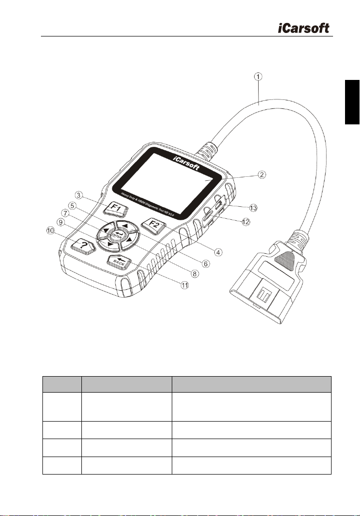
3.1 Outline of HD V3.0
Figure 3-1
Table3-1:
No.
Name
Descriptions
①
Cable with OBD II
Connector
Connects the HD V3.0 to the vehicle‟s
Data Link Connector (DLC).
②
LCD display
Indicates test result
③
F1 Function button
In case of special use
④
F2 Function button
In case of special use
Heavy Duty & OBDII Diagnostic Tool HD V3.0
8
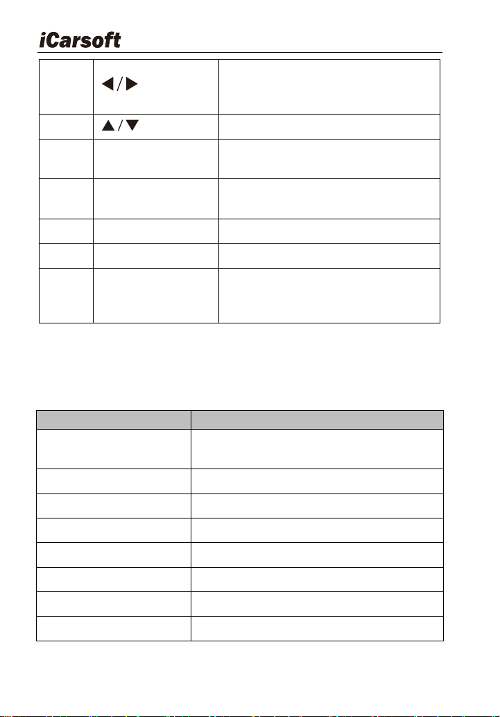
⑤/⑧
button
Move cursor right or left for selection ;
Or turn page up or down when more
than one page is displayed.
⑥/⑨
button
Move cursor up or down for selection
⑦
Enter button
Confirms a selection (or action) from a
menu list.
⑩
? button
Shows help information for test results
or user operation.
⑪
Back button
Returns to the previous menu
⑫
Storage Card Slot
Holds the system of the scan tool.
⑬
USB port
Connects the scan tool for power
supply and update the software if
needed.
3.2 Specifications
Table3-2:
Item
Description
Display
2.8 "TFT 262K true color, 320 x 240
QVGA LCD display
Input voltage range
8-32V
Operating current
< 100mA@12V(Typical)
Power consumption
<1.2W(Typical)
Operating temperature
32°F ~122°F / 0°C -50°C
Storage temperature
-4°F ~158°F / -20°C -70°C @RH60 %
Outline dimension
4.7‟ x 3.2‟ x 1.0‟ / 121 x 82 x 26mm LWH
Weight
<17.6 oz (500g)
Heavy Duty & OBDII Diagnostic Tool HD V3.0
9
EN
3.3 Accessories
Table3-3:
Name
Description
User manual
Instruction on tool operations
Data Cable
Allows easy update via a PC and internet
connection
6PIN and 9PIN DLC
adaptor
Connects tools with Vehicle to use
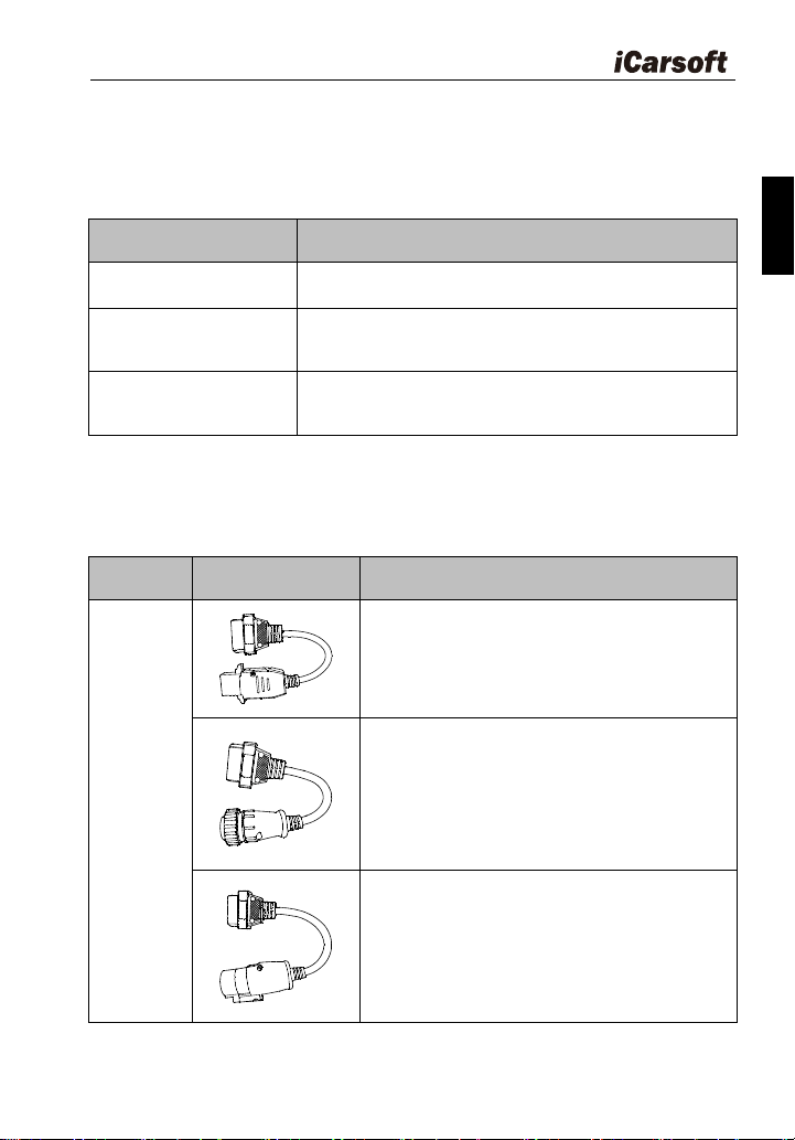
HD V3.0 also supports the following optional adaptor kits, which can be
purchased separately by contacting the dealer if necessary.
Table3-4:
Name
outline
Description
Optional
adaptors
1) 8Pin V2 for VOLVO
2) 16Pin for SCANIA
3) 30Pin V2 for IVECO
Heavy Duty & OBDII Diagnostic Tool HD V3.0
10
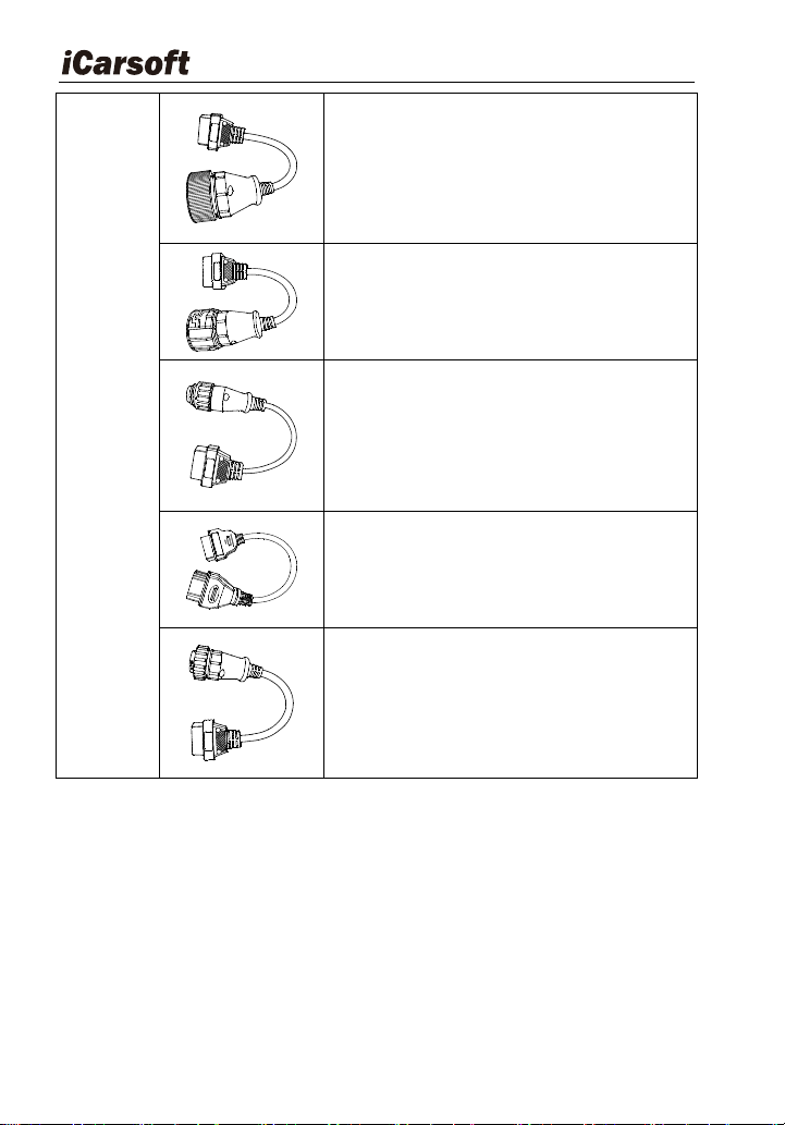
4) 37Pin for MAN
5) 12Pin for MAN
6) 7Pin for KNORR WABCO TRAILER
7) 12Pin for RENAULT
8) 14Pin OBD
3.4 Power supply
The power of the Diagnostic Tool is provided via the vehicle‟s Data Link
Connector (DLC). Follow the steps below to power it up:
1. Find DLC on heavy duty vehicle:
The DLC is the connector where diagnostic code readers interface
with the vehicle‟s on-board computer and usually located in the
driver‟s cab.
A plastic DLC cover may be found for some vehicles and you need
Heavy Duty & OBDII Diagnostic Tool HD V3.0
11
EN
to remove it before plugging DLC. If it cannot be found, refer to the
vehicle‟s service manual for the location.
2. Connect the data link connector to the interface of the data link
connector of the heavy duty.
4 Connections & General Operations
4.1 Connections
1. Turn the ignition off.
2. Locate the heavy duty vehicle‟s DLC.
3. Select the desired diagnostic adaptor according to your vehicle‟s DLC.
4. Plug one end of 6pin or 9pin DLC diagnostic adaptor into the included
OBD II 16pin connector, and connect the other end to the heavy duty
truck‟s DLC.
5. Turn the ignition on. Engine can be off or running.
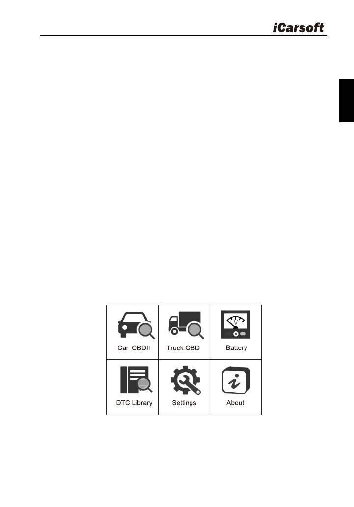
6. After finishing, the system will enter the main menu interface, as shown
in Figure 4-1.
Figure 4-1
The following table briefly describes the functions of the main menu of
the diagnostic tool.
Heavy Duty & OBDII Diagnostic Tool HD V3.0
12
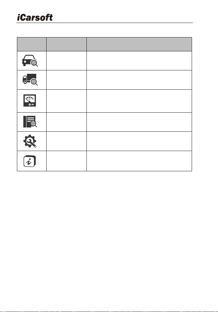
Table4-1:
Function
icon
Name
Descriptions
Car OBDII
To diagnose your car OBD II.
Truck OBD
To diagnose your heavy-duty truck
Battery
Displays the voltage of the data link
connector (DLC)
DTC Library
Select DTC Library icon to view the
definition of the DTC.
Settings
Set the language, unit, buzzer, etc. of the
diagnostic tool.
About
It mainly includes software version,
hardware version, serial number, support
protocol.
CAUTTION: Don‟t connect or disconnect any test equipment with ignition on
or engine running.
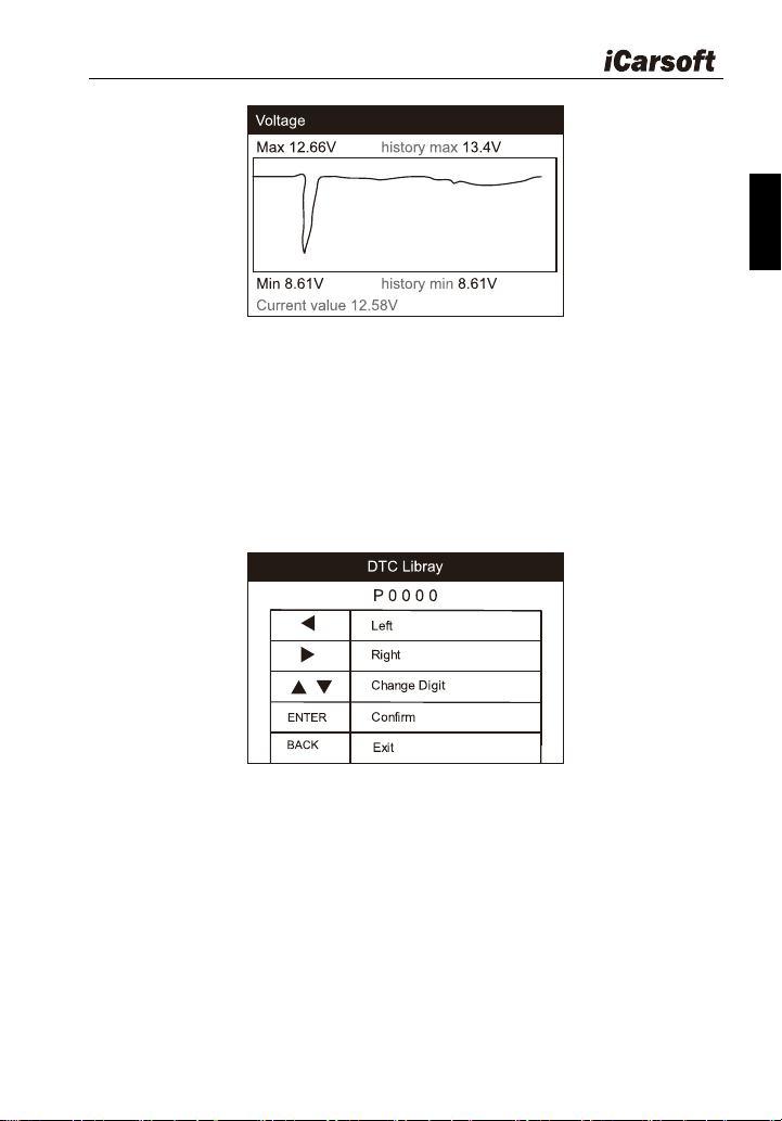
4.2 Battery
On battery voltage page, it shows the voltage of Data Link Connector
(DLC), which is approximately the vehicle battery‟s status. Especially, it can
observe the voltage while engine start.
Heavy Duty & OBDII Diagnostic Tool HD V3.0
13
EN
Figure 4-2
4.3 DTC Library
Select DTC Library icon from the main screen, press ENTER. Press
LEFT / RIGHT button to move the highlight bar to different position. Press UP
/ DOWN button to alter the value, and press [ENTER] button, the screen will
display definition of the DTC.
Figure 4-3
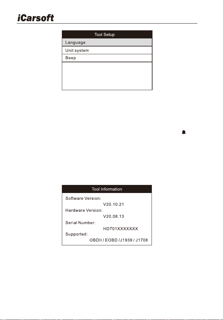
4.4 Settings
Select “Settings” icon on the main menu and press [ENTER] button. The
system will enter the system setup screen:
Heavy Duty & OBDII Diagnostic Tool HD V3.0
14
Figure 4-4
1) Language: Configure the system language to your preference.
2) Unit system: Set the measurement unit system.
3) Beep: Turn ON/OFF the Beeper. Once Beeper is set to ON, will
appear at bottom of the screen.
4.5 About
Select About icon on the main screen, press ENTER. On the Tool
Information page, there are software version, hardware version and product
serial number etc..
Figure 4-5
5 Diagnose
From the main menu, select the car OBDII or truck OBD icon.
If a heavy-duty truck is diagnosed, the system will continue scanning the
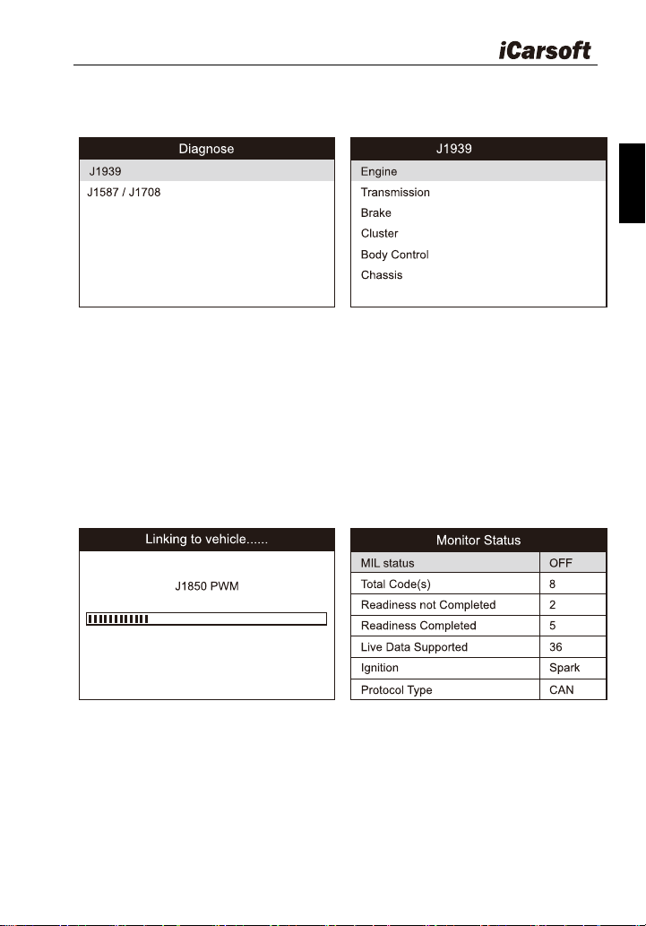
Heavy Duty & OBDII Diagnostic Tool HD V3.0
15
EN
protocols the truck supports and then enter the system selection screen. See
figure 5-1.
Figure 5-1
For detailed operations, please refer to Chapter 5.1 "Truck OBD
Diagnosing".
If a vehicle equipped with Car OBDII is tested, the system will enter the
function selection screen once scanning has finished successfully. See figure
5-2
Figure 5-2
Press [ENTER] to enter the system selection screen. For detailed
operations, please refer to Chapter 5.2 "Car OBDII Diagnosing".
Heavy Duty & OBDII Diagnostic Tool HD V3.0
16
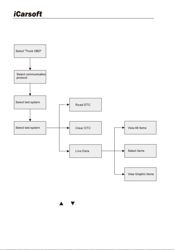
5.1 Truck OBD Diagnosing
Follow the diagnosis flowchart shown as below to proceed:
Figure 5-3
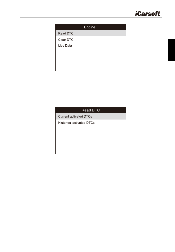
In Figure 5-4, use [ ] / [ ] button to select the desired system and
press ENTER to access:
Heavy Duty & OBDII Diagnostic Tool HD V3.0
17
EN
Figure 5-4
5.1.1 Read DTC
This option is used to read the current activated or historical activated
codes.
Figure 5-5
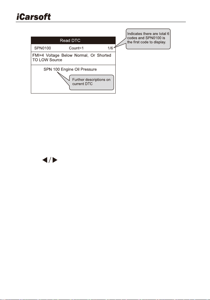
Generally, there are three elements for one J1939 DTC (See Figure
5-6):
Suspect Parameter Number (SPN) – Indicates what function on the
ECU has failed.
Failure Mode Indicator (FMI) – Indicates in what way the function
failed.
Occurrence (OC) - Indicates the occurrence times of the current DTC.
Heavy Duty & OBDII Diagnostic Tool HD V3.0
18
Figure 5-6
Whereas, if we choose [J1587/1708], the fault code includes:
Subsystem Identifier (SID) – Indicates what function on the ECU has
failed.
Failure Mode Indicator (FMI) – Indicates in what way the function
failed.
Occurrence (OC) - Indicates the occurrence times of the current DTC.
Press [ ] to view the next or previous trouble code; press [ BACK]
to exit and return to the function screen.
5.1.2 Clear DTC
This option allows you to clear the existing or historic trouble codes.
Note: After clearing, you should retrieve trouble codes once more or turn
ignition on and retrieve codes again. If there are still some trouble codes in
the system, please troubleshoot the code using a factory diagnosis guide,
then clear the code and recheck.
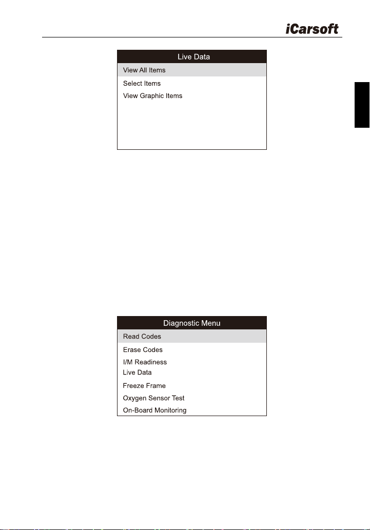
5.1.3 Live Data
This option enables you to read the real-time data stream in character or
graphic form.
Heavy Duty & OBDII Diagnostic Tool HD V3.0
19
EN
Figure 5-7
A. View All Items: To view all data stream items.
B. Select Items: Select the desired data stream items, and then press
[ENTER] to read the value of the selected items.
C. View Graphic Items: Select the desired data stream item and press
[ENTER] to display it in live graphic form.(Note: Max. 1 item is
supported.)
5.2 Car OBDII Diagnosing
Press [ENTER] in Figure 5-2, a screen similar to Figure 5-8 will appear:
Figure 5-8
5.2.1 Read Codes
This option is used to read the current, pending or permanent trouble
codes. If the trouble code is found, the system will display the detailed
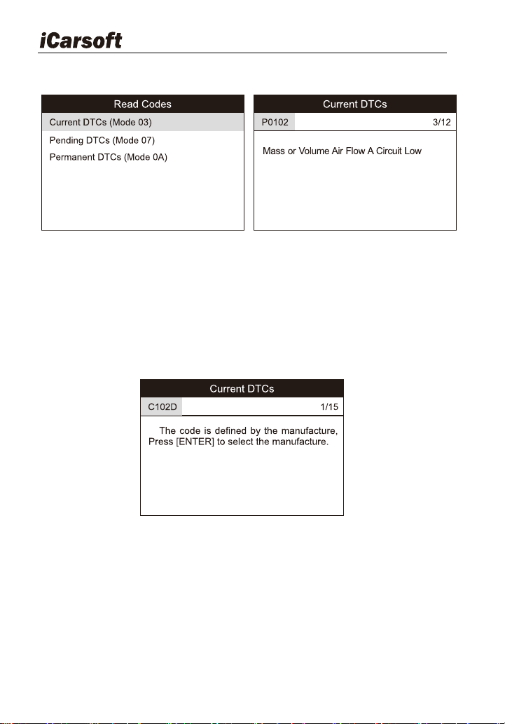
Heavy Duty & OBDII Diagnostic Tool HD V3.0
20
description of the trouble code:
Figure 5-9 Figure 5-10
In Figure 5-10, 3/12 indicates there are total 12 codes and P0102 is the third
code to display.
If the DTC is defined by the manufacturer, a screen similar to Figure 5-11 will
appear. In this case, press ENTER to select the manufacturer from the list
and the screen will show the detailed content of the trouble code.
Figure 5-11
5.2.2 Erase Codes
It is used to clear all existing trouble codes.
Notes: Before performing this function, make sure to retrieve and record the
trouble codes.
After clearing, you should retrieve trouble codes once more or turn ignition on

Heavy Duty & OBDII Diagnostic Tool HD V3.0
21
EN
and retrieve codes again. If there are still some trouble codes in the system,
please troubleshoot the code using a factory diagnosis guide, then clear the
code and recheck.
5.2.3 I/M Readiness
I/M refers to Inspection and Maintenance that is legislated by the
Government to meet federal clean-air standards. I/M Readiness indicates
whether or not the various emissions-related systems on the vehicle are
operating properly and are ready for Inspection and Maintenance testing.
The purpose of the I/M Readiness Monitor Status is to indicate which of
the vehicle‟s Monitors have run and completed their diagnosis and testing,
and which ones have not yet run and completed testing and diagnosis of their
designated sections of the vehicle‟s emissions system.
The I/M Readiness Monitor Status function also can be used (after repair
of a fault has been performed) to confirm that the repair has been performed
correctly, and / or to check for Monitor Run Status.
Note: N/A means not available on this vehicle; INC means incomplete or not
ready and OK means completed or Monitor ok.
5.2.4 Live Data
This item enables you to view all data stream items and the live
waveform of all selected items.
5.2.5 View Freeze Frame
When an emission-related fault occurs, certain vehicle conditions are
recorded by the on-board computer. This information is referred to as freeze
frame data. Freeze Data is a snapshot of the operating conditions at the time
of an emission-related fault.
Note: If DTCs were erased, Freeze Data may not be stored in vehicle
memory depending on vehicle.
5.2.6 Oxygen sensor test
The results of oxygen sensor test are not live values but instead the

Heavy Duty & OBDII Diagnostic Tool HD V3.0
22
results of the ECU‟s last oxygen sensor test. For live oxygen sensor readings,
refer to any of the live sensor screens such as Graph Screen.
Not all test values are applicable to all vehicles. Therefore, the list
generated will vary depending on vehicle. In addition, not all vehicles support
the Oxygen Sensors screen.
5.2.7 On-board monitor test
This function can be utilized to read the results of on-board diagnostic
monitoring tests for specific components / systems.
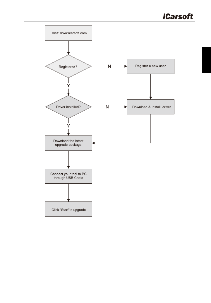
6 How to Upgrade HD V3.0
6.1 Upgrading flowchart
Heavy Duty & OBDII Diagnostic Tool HD V3.0
23
EN
Figure 6-1
6.2 User registration
As you buy a HD V3.0, please visit www.icarsoft.com to register. Only af
ter successfully registered, you can logon at the site and can download the
HD V3.0 driver & latest version program of HD V3.0.
Heavy Duty & OBDII Diagnostic Tool HD V3.0
24
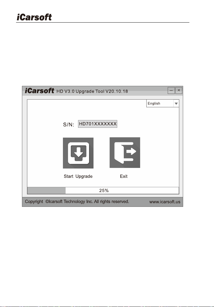
6.3 Upgrading:
Log on www.icarsoft.com, download the latest version of the HD V3.0
upgrade package and decompress the software to local disk.
Connect the HD V3.0 to computer through USB cable and run the HD
V3.0 Upgrade Tool.exe, the following window will appear:
Figure 6-2
Select the language, and then click " Start Upgrade", a progress bar will
appear at the bottom of the screen. When a message of upgrade success
pops out, click "Exit" and then unplug the USB cable to complete upgrade.
7 FAQ
Here we list some frequently asked questions and answers relating to
HD V3.0.

Heavy Duty & OBDII Diagnostic Tool HD V3.0
25
EN
Question: System halts when reading data stream. What is the reason?
Answer: It may be caused by a slackened connector. Please turn off the
diagnostic tool firmly connect the connector, and switch on it again.
Question: Screen of main unit flashes at engine ignition start.
Answer: Caused by electromagnetic disturbance and this is normal
phenomenon.
Question: There is no response when communicating with on-board
computer.
Answer: Please confirm the proper voltage of power supply and check if the
throttle has been closed, the transmission is in the neutral position, and the
water is in proper temperature.
Question: Why are there so many fault codes?
Answer: Usually, it caused poor connection or fault circuit grounding.
Note: All pictures illustrated here are for reference and demonstration
purpose only and this User‟s Manual is subject to change without prior notice.


Icarsoft Technology Inc.
All Rights Reserved
www.icarsoft.us
www.icarsoft.com
2020-11-03
Version: A0