User’s Manual
For BMM V3.0 / MB V3.0 / VAWS V3.0 / POR V3.0 / VOL
V3.0 / OP V3.0 / LR V3.0 / US V3.0 / FR V3.0 / JP V3.0 / FA
V3.0 / KR V3.0 / CR V3.0
Multi-system Car Diagnostic Tool series
PROFESSIONAL . FAST . SMART . POWERFUL


EN
Contents
1 PRODUCT DESCRIPTIONS .................................................................. 1
2 SPECIFICATIONS ................................................................................... 2
3 ACCESSORIES INCLUDED .................................................................. 2
4 PRODUCT FEATURES ........................................................................... 2
5 VEHICLE COVERAGE............................................................................ 5
6 OPERATION ............................................................................................ 5
6.1 DIAGNOSE................................................................................................. 6
6.1.1 Vehicle identification .................................................................. 6
6.1.2 Diagnostic mode .......................................................................... 8
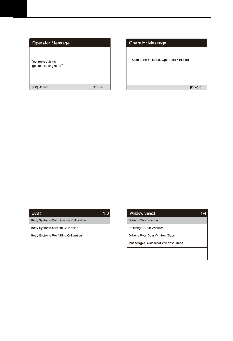
6.1.3 Diagnostic operation ................................................................ 10
6.2 SERVICE FUNCTION ................................................................................ 18
6.2.1 Oil Reset ....................................................................................... 19
6.2.2 EPB ................................................................................................ 21
6.2.3 BMS ............................................................................................... 22
6.2.4 DPF ................................................................................................ 23
6.2.6 SAS ................................................................................................ 25
6.2.5 ETC ................................................................................................ 26
6.2.7 ABS Bleeding.............................................................................. 27
6.2.8 Injector ......................................................................................... 28
6.2.9 Head Lamp .................................................................................. 30
6.2.10 Air Suspension ........................................................................ 31
6.2.11 TPMS ........................................................................................... 32
6.2.12 Air-conditioner ......................................................................... 33
6.2.13 Fuel pump ................................................................................. 34
6.2.14 Engine Idle ................................................................................ 35
6.2.15 Body stability............................................................................ 36
6.2.16 Air Filter ..................................................................................... 37
6.2.17 Door ............................................................................................ 38

EN
6.2.18 Seat ............................................................................................. 39
6.3 BATTERY VOLTAGE TEST ....................................................................... 40
6.4 OBDII / EOBD ...................................................................................... 40
6.5 DTC LOOKUP......................................................................................... 41
6.6 REVIEW AND REPORT ............................................................................ 41
6.7 SETUP..................................................................................................... 41
6.7.1 Language ..................................................................................... 41
6.7.2 Unit of Measure .......................................................................... 42
6.7.3 Buzzer .......................................................................................... 42
6.7.4 LOG ............................................................................................... 42
6.7.5 Clear Data .................................................................................... 42
6.7.6 Factory Data Reset ................................................................... 42
6.8 HELP ....................................................................................................... 43
6.9 ABOUT .................................................................................................... 43
7 WARRANTY ........................................................................................... 43
7.1 LIMITED ONE YEAR WARRANTY ............................................................ 43
7.2 SERVICE PROCEDURES ......................................................................... 44
8 SOFTWARE UPDATE&DATA PRINT .................................................. 44
8.1 UPDATE PROCEDURES: ......................................................................... 44
8.2 DATA PRINT PROCEDURES: ................................................................... 47
EN
1
Multi-system Car Diagnostic Tool series
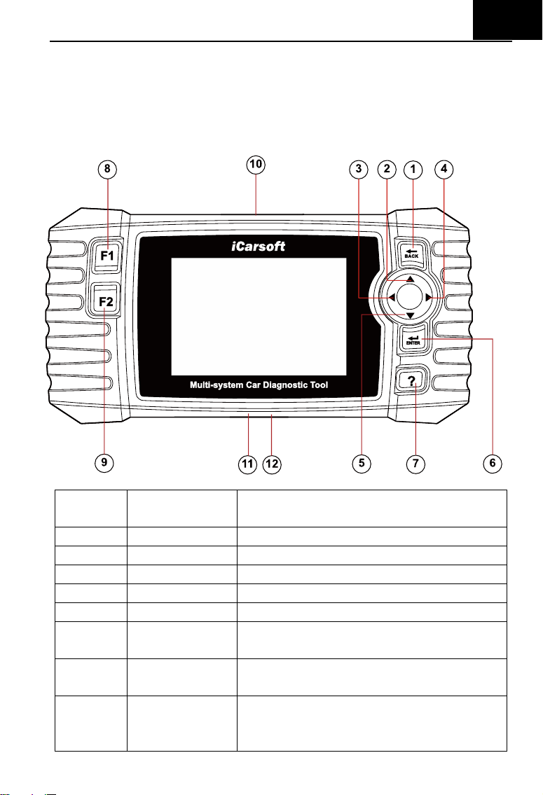
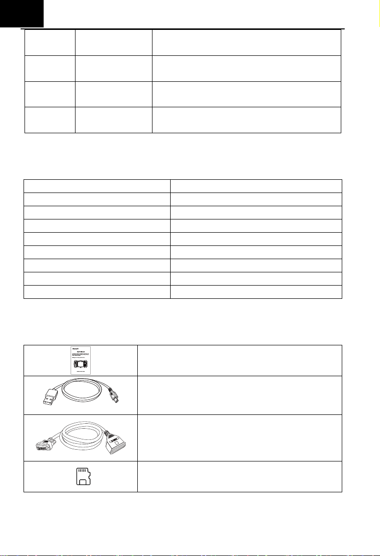
1 Product Descriptions
Serial
Number
Button Name
Description
1
BACK Button
Returns to previous menu
2
UP Button
Moves cursor up for selection
3
LEFT Button
Moves cursor left for selection
4
RIGHT Button
Moves cursor right for selection
5
DOWN Button
Moves cursor down for selection
6
ENTER Button
Confirms a selection (or action) from a
menu list
7
HELP Button
Shows help information for test results or
user operation.
8
F1 Function
Button
In case of special use
EN
2
9
F2 Function
Button
In case of special use
10
OBDII
Connector
Connects the scan tool to the vehicle’s
Data Link Connector via OBDII Cable
11
Storage Card
Slot
Holds the system of the scan tool.
12
DATA Cable
Connector
Connects the scan tool for power supply
and update the software if needed.
2 Specifications
Item
Description
Display
4.0” TFT LCD,With 480*320 Pixels
Operation Temperature
0° C ~50° C
Storage Temperature
-20° C ~70° C
Operating Voltage
9-18V
Operating Current
150mA@12V(Typical)
Power Consumption
1.8W(Typical)
Dimension
206*104.1*32.6mm(L*W*H)
Weight
<350g
3 Accessories Included
User’s manual
Instruction on tool operations
Data Cable
Allows easy update via a PC and internet
connection
OBDII Main Cable
Connects tools with Vehicle to use
Storage Card
Download Vehicle program
4 Product Features

EN
3
1) iCarsoft Multi-system Car Diagnostic tool V3.0 Series can do it all-reads
and clears trouble codes on all the systems such as engine ,transmission,
ABS and airbag etc.
2) Support OBDII / EOBD Ten Modes of Operation.
3) Read Live Data.
4) Full ECU Diagnosis.
5) Applies to the single Brand of all Models equipped with OBDII-16DLC.
6) Easy To Use with Silicone Keys.
7) Auto identify technology can automatically identify model and year
information in no time.
8) Actuation Test / Bi-directory Test is used to access vehicle-specific
subsystem and component tests.
9) Basic Setting means reset some basic parameter settings for each control
module, especially some parts / sensors, etc.
10) Adaption, this function allows you to perform adaptive learning / reset /
calibration and other functions for each control module, and also includes
some important module data for parameter adjustment.
11) Support Freeze Frame of Fault Code functions.
12) Oil Light / Service Reset: Support service lamp reset.
13) Electronic Parking Brake (EPB) system maintenance, deactivates and
reactivates the EPB system for replacement and initialization.
14) Battery Management System (BMS), registers new battery to the BMS
while battery replacement.
15) Diesel Particulate Filter (DPF) regeneration control system, request the
DPF regeneration process while DPF blockage and turn off the DPF
indicator.
16) Electronic Throttle Control system (ETC), relearns the throttle valve
control value while clear or replace the throttle value.
17) SAS: Steering Angle Sensor (SAS) calibration, calibrates the steering
wheel to straight ahead, or recalibrates SAS while steering part
replacement.
18) ABS Bleeding (BLD), Release the air to restore ABS brake sensitivity, or
relearn while ABS replaced.

EN
4
19) Injector Coding (INJ), relearn the injector control parameter while the
injector renewed or replaced.
20) Head Lamp is about the headlamp maintenance, maintenance and other
related operations (including AFS setting), and then perform this function
for calibration.
21) Air Suspension: After maintenance, replacement and other operations of
the suspension height sensor are performed in all aspects, this function
needs to be executed for suspension learning and calibration.
22) The TPMS service function include displaying sensor IDs from the
vehicle’s ECU, inputting TPMS sensor replacement IDs and testing
sensors.
23) Fuel pump, carry out this function, activate the replaced fuel pump, make
the car start can inject fuel normally, make the engine achieve the ideal
running state.
24) Air-conditioner, when the air conditioning system can not work normally,
this function can be performed, and the air conditioner can be activated for
a period of time to match the replaced refrigerant, blower pump and other
automotive components.
25) Engine Idle, adjust the engine speed at idle speed.
26) Body stability, learning and calibration after replacing body stability control
unit and other related components.
27) Air Filter, the disassembly, repair or replacement of the air filter will cause
some particles and impurities in the air to enter the parts of the car. It is
necessary to carry out the air filter learning and matching function to make
the air filter work normally.
28) Door, this function can provide users with calibration after maintenance or
replacement of window lifting motor. Such as window calibration.
29) Seat, this function can provide users with calibration after repairing or
replacing the seat position drive motor. Such as driver's seat calibration,
passenger’s seat calibration, etc.
30) The Print Data function allows you printing out diagnostic data recorded
by the scan tool or customized test reports.
31) Battery test allows you getting the voltage of battery with OBD port by the
scan tool when the engine starts.

EN
5
32) DTC Library to lookup when user is operating this tool.
33) Upgrade Via PC.
34) Multi-language: English, German, Dutch, Spanish, French.
Note:
Certain functions may be limited from the vehicle manufacturer due to the
requirement of a special factory access code.
This scan tool covers over 20 years of models, so some functions may not be
available on all years / models.
5 Vehicle Coverage
iCarsoft Multi-system Car Diagnostic Tool V3.0 Series is a Professional
and powerful vehicle fault diagnosis tool developed by iCarsoft Technology Inc.
With a 4.0” TFT LCD and unique diagnostic software, it features full ECU
diagnosis of single vehicle brand and test modes mainly include: CANBUS,
ISO9141, KWP2000, and J1850 etc . It enables technicians to accurately
diagnose complex problems. CR V3.0 is Multiple Choice of Vehicle Brands.
6 Operation
Note:
Welcome to using the scan tool of icarsoft, you should do something before
using the scan tool.
At first, please check production list such as scan tool and accessories
already when you open the package, read the user’s manual and connect
the OBDII cable to scan tool.
There are two ways to provide power the scan tool, one way is using data
cable external 5V power adapter or USB port, another way is using OBDII
Cable connection to the vehicle’s Data Link Connector.
Don’t open the scan tool in a rainy environment or in the absence of
training. Don’t soak the scan tool as the keypad and port are not
waterproof, also no solvents such as alcohol are allowed to clean the
keypad or display.
You can set the language, Unit of Measure and Buzzer your wanted when
EN
6
the scan tool connected power.
Make sure the ignition is ON when you connected the scan tool already.
Note:
For vehicles manufactured by different vendors, it is possible that it has
different diagnostic menus. For details, please follow the instructions on the
screen to proceed.
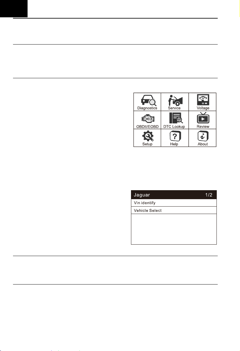
6.1 Diagnose
This function is specially designed to
diagnose electronic control system of
single vehicle model connected the scan
tool already.
The diagnostic application connects data to
the electronic control system of the test
vehicle used for vehicle diagnostics. The application performs function tests to
retrieve vehicle diagnostic information such as fault and event codes and
real-time data for various vehicle control systems such as engine,
transmission and ABS.
6.1.1 Vehicle identification
When the device is connected to the
vehicle, there are two ways to enter the
diagnostic system:
1. Auto identify or VIN identify
2. Vehicle select
Note:
“Auto identify” or “VIN identify” will be displayed on the interface, depending on
the vehicle type.
6.1.1.1 Auto identify
By reading the vehicle specific information (including VIN identify), the
vehicle identification can be carried out quickly.
6.1.1.2 VIN identify
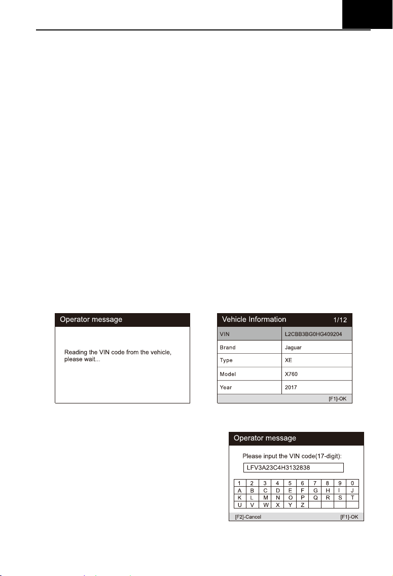
EN
7
The “VIN identify” can automatically parse the car model, eliminating the
cumbersome program manually input by the user.
The device diagnostic system has the latest automatic identification
function based on the vehicle identification number. It stores all the
diagnosable electronic control units of Scan on the vehicle and performs the
diagnosis on the selected system. Perform automatic VIN recognition. For
some vehicles that do not support the automatic vehicle identification number
scanning function, the diagnostic tool allows you to manually enter the vehicle
identification number. Recognize the VIN first. If the VIN cannot be recognized,
you need to enter it manually.
Automatic VIN identification
To perform Auto VIN identification
1. Click the Diagnostics application button from the device’s Job Menu. The
Vehicle Menu displays.
2. Click the vehicle manufacturer button to go to the next level menu.
3. Select VIN identify. Once the test vehicle is successfully identified, the
screen will show the Vehicle Identification, then tap OK to enter the
diagnosis.
Manual VIN input
To perform Manual VIN input
1. Perform the first 2 steps of automatic
VIN identification.
2. If the automatic VIN matching is not
successful, or if the VIN does not
match, a VIN input box will pop up,
manually input the VIN.
EN
8
6.1.1.3 Vehicle Select
When the vehicle cannot be retrieved automatically through the ECU of
the vehicle, or the specific VIN is unknown, you can manually select the
vehicle. Or in some cases, when the user selects vehicle selection rather than
vehicle VIN scanning, the system will provide the option of vehicle selection,
and the user can select the vehicle model, model year, etc. according to his
own model.
To perform vehicle selection:
1) Click the diagnostic application button in the device’s job menu. Vehicle
menu display.
2) Select the brand of the test vehicle.
3) Choose the "vehicle selection" option to make a series of selections
according to the on-screen prompts, select the correct vehicle model,
model year, etc.
4) Select step by step according to the screen prompts, and finally enter the
list of diagnosis modes.
5) The user performs various operations by selecting the diagnostic mode.
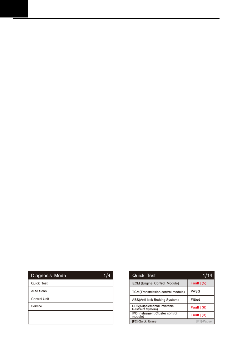
6.1.2 Diagnostic mode
The scan tool provides five diagnostic modes for users to choose, as
shown in the figure below: Quick Test, Auto Scan, Control Unit, Service, Quick
Erase. For the quick erase mode, it is in the form of a button. Users need to go
to the next layer to quickly clear the vehicle fault information recorded in the
diagnosis process.

EN
9
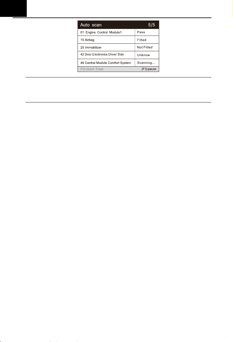
1) Quick test
Scan the control unit of the whole
vehicle, At the same time, the fault
information of each control unit is
detected to show the control unit list
and fault status.
Left side --- Show vehicle control unit number and system name.
Right side --- Show vehicle control unit status.
Fault | 5 : Indicates that the fault code is detected; 5 represents the
number of faults detected.
Pass: Indicates that the vehicle is equipped with this system and
has no fault code.
Fitted: Indicates that the vehicle is equipped with this system.
Not Fitted: Indicates that it is detected that the vehicle is not
equipped with this system.
Unknown: Indicates that it is detected that it is unknown whether
the vehicle is equipped with this system.
Scanning: Indicates that the device is scanning the vehicle system.
[Quick Erase] --- Press this button to quickly clear the fault code.
[Pause] / [Continue] --- Press this button to pause or continue scanning.
2) Auto scan
Select this option to automatically diagnose and scan all systems on the
vehicle. The following figure shows the operation interface of the
automatic scanning function:
EN
10
Note:
If quick test is performed first and then auto scan is performed, the
diagnostic status will be memorized.
3) Control Unit
This option allows you to manually locate the desired control system.
According to the menu driven program, the user manually selects the
specified control unit that he wants to detect, skips the whole vehicle
scanning, and directly carries out the diagnosis of the specified system.
4) Service
The car diagnostic tool provides an entry from the diagnostic mode to the
service function. You can easily select the service function from the
diagnosis mode, without returning to the service menu for selection. For
different models, the service functions are different. Select this option to
perform regular maintenance, such as reset oil service lamp and
calibrating different systems.
5) Quick erase
Quickly clear the vehicle fault information recorded in the diagnosis
process.
6.1.3 Diagnostic operation
The main function menu options of different vehicles will vary slightly, and the
main function menu usually includes the following options:
1. Module Information --- Read complete electronic system module
information.
2. Read fault code --- This function reads and displays the fault codes
retrieved from the vehicle control system.
EN
11
3. Clear fault memory --- Use this function to clear the original fault code
after reading the vehicle fault code and completing the repair.
4. View data --- When this function is selected, the data list of the selected
module will be displayed on the screen.
5. Actuation Test --- This function provides access to vehicle specific
subsystem tests and component tests.
6. Basic settings --- Basic Setting means reset some basic parameter
settings for each control module, especially some parts / sensors, etc.
7. Adaptation --- this function allows you to perform adaptive learning /
reset / calibration and other functions for each control module, and also
includes some important module data for parameter adjustment.
Note:
The function list will vary according to different models, and the actual
products shall prevail.
To perform diagnostic functions:
1) Select “Diagnostic” icon.
2) Select Vehicle Manufacturer. And select the version.
3) Select vehicle selection and select vehicle model, model year, etc.
according to the on-screen prompts.
4) Select the diagnosis mode and guide the selection through the menu of
any diagnosis mode to locate the required test system.
5) Select the test to be performed on the function list.
Module Information --- Read full electronic system module information,
such as VIN, part number, version, supplier, production date of ECU, Also
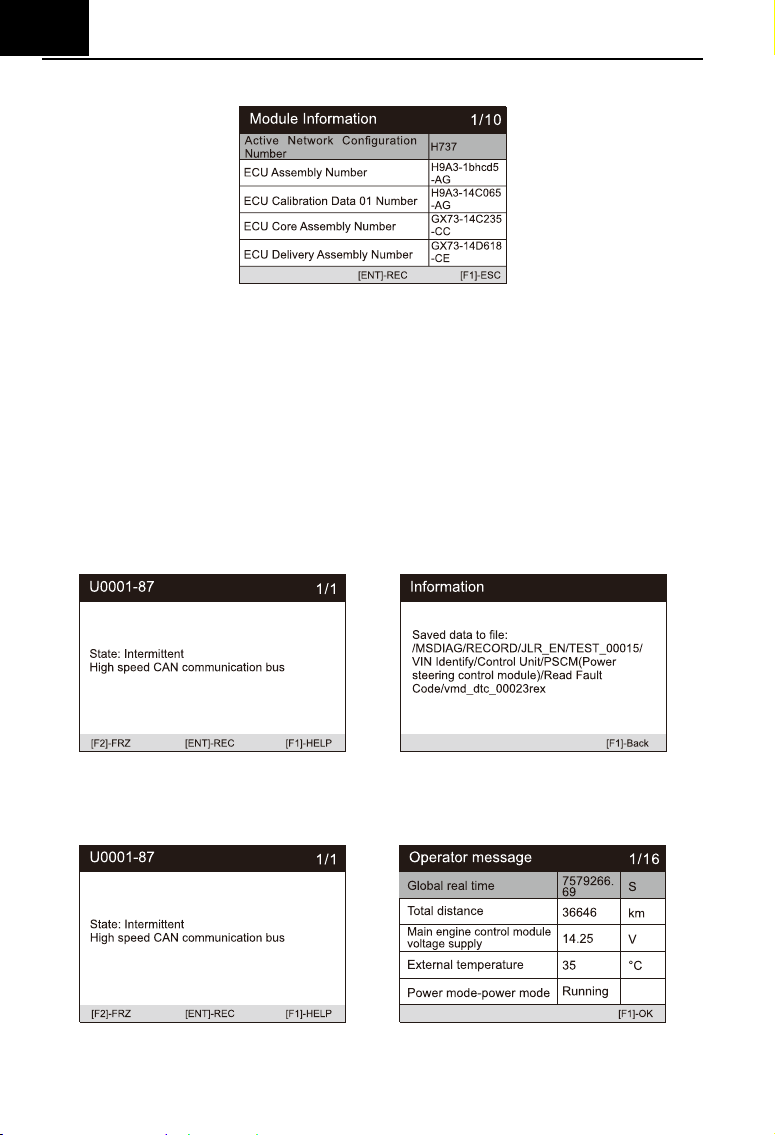
EN
12
you can save these data by press [REC].
Read fault code --- This function reads and displays the fault codes
retrieved from the vehicle control system. Read the fault code of all
electronic system module, display the fault status and description code. In
addition, you can press [REC] to save the fault information. The "read
fault code" interface varies according to the test vehicles, and some
vehicles can also read frozen frame data.
a) After press the [REC] button, the screen will display the recorded
data storage path, and the recorded fault code information can be
read on the computer. as shown in the figure below.
b)
Press the [FRZ] button to view the frozen frame information of fault
code, as shown in the figure below.
c) Press the [HELP] button to read the help information. as shown in
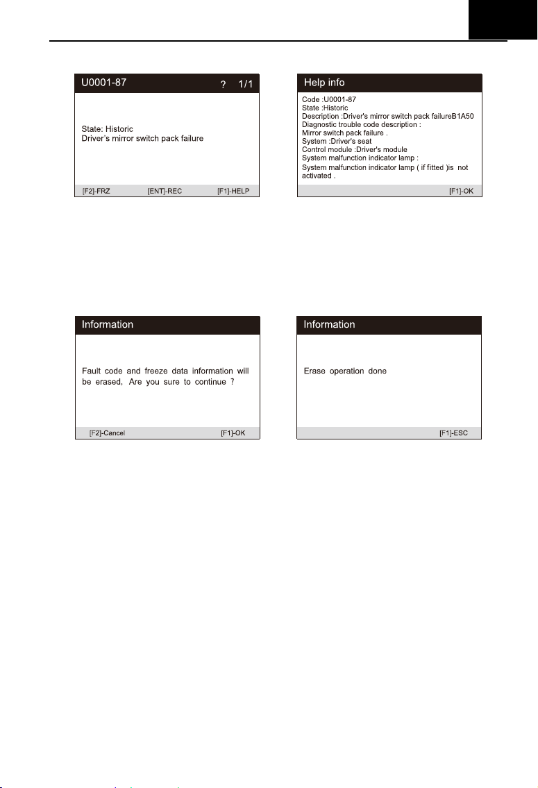
EN
13
the figure below.
Clear fault memory – After reading the vehicle fault code and completing
the repair, this function can be used to clear the original fault code. Before
clearing the fault code, make sure the vehicle engine is off and the ignition
key is in the on (run) position. Erase full electronic system module fault
code and diagnostic related freeze frame information.
How to clear the fault code:
1) Select the [Clear fault code] on the "function menu"
2) At this time, a warning message will appear on the screen, indicating
that the fault code and frozen data information will be cleared.
a) Select [OK] to continue. After the operation is successful, an
interface will be displayed on the screen.
b) Select [Cancel] to exit.
3) Re-enter the [Read fault code] function to retrieve the fault code to
ensure the successful code clearing operation.
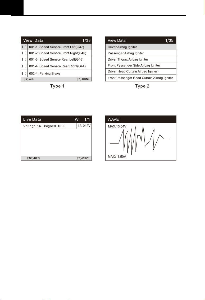
View data –When this function is selected, a list of data for the selected
module is displayed on the screen. The options available for different
vehicle control modules will vary. These parameters are displayed in the
order sent by the electronic control module, so there will be differences
EN
14
between different vehicles. Read full electronic system module live data
by text value or waveform. Also you can save these data by press [REC].
When there is [W] in the upper right corner of the data stream, select
[WAVE] to display the waveform, as shown in the following figure:
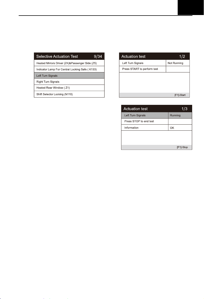
Actuation Test --- The "Actuation Test" function accesses vehicle specific
subsystem tests and performs component tests. The available test
functions vary according to the manufacturer, year and model, and the
menu will only show the available test options.
When performing the actuation test, the tester inputs the command to the
ECU to drive the actuator. This test can monitor the operation of the
actuator by reading the ECU data of the engine. For example, by
repeatedly switching the two working states of the solenoid valve, relay
and switch, it can determine whether the system or components are
working normally, and execute the command of the switch on the door or
window.
Left / Right turn signals
Through the left / right turn signal action test item, you can control
the left and right turn signal flashing to test whether the turn signal
works normally.
EN
15
To perform signal turn signal lamp action test (take left turn signal
lamp as an example):
1) Enter the action test and select left turn signals.
2) At this time, the signal indicator is not running.
3) Press the [Start] button to
execute the action.
4) At this time, the signal
indicator is running,
indicating that the action is
being executed. Press the
[stop] button to stop.
Window regulator front / rear left / right: down / up
Through the window regulator action test item, you can control the
whole vehicle window up and down to test whether the window up
and down works normally.
Windshield wiper motor (V) stage 1 / 2
Through the action test item of windshield wiper motor, the wiper
can be controlled to work at 1 / 2 gear to test whether the wiper
motor works normally
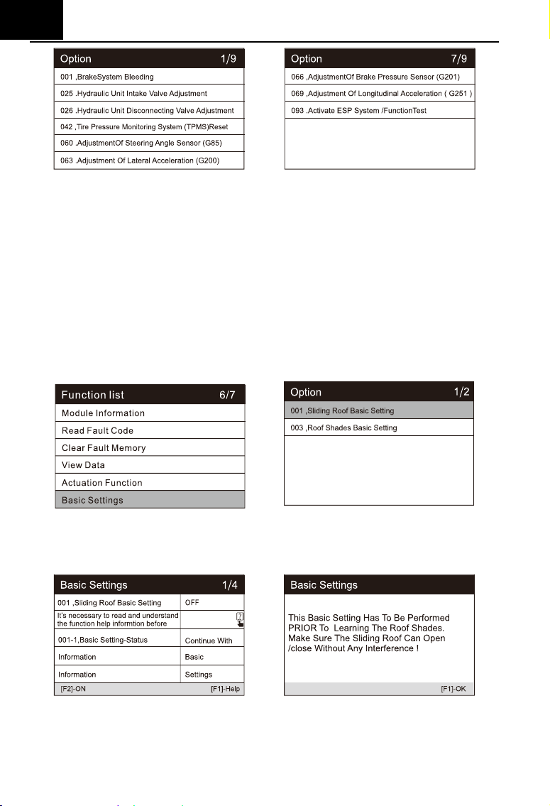
Basic settings --- Basic Setting means reset some basic parameter
settings for each control module, especially some parts / sensors, etc.
EN
16
Focus on the following three functions:
Sliding Roof Basic Setting
After the maintenance of the skylight, it is necessary to use the basic
setting to re match and learn the stop point value of the automatic
skylight at each position.
To Preform Sliding Roof Basic Setting:
1) Sliding roof basic setting is required after the maintenance of
the sunroof,access basic settings,select Sliding Roof Basic
Setting.
2) The basic settings of the sliding roof is closed. Press the help
button to display help information.
3) Press the [Help] button to display a prompt message as above.
4) Then press the [ON] button to rematch and learn the stop point
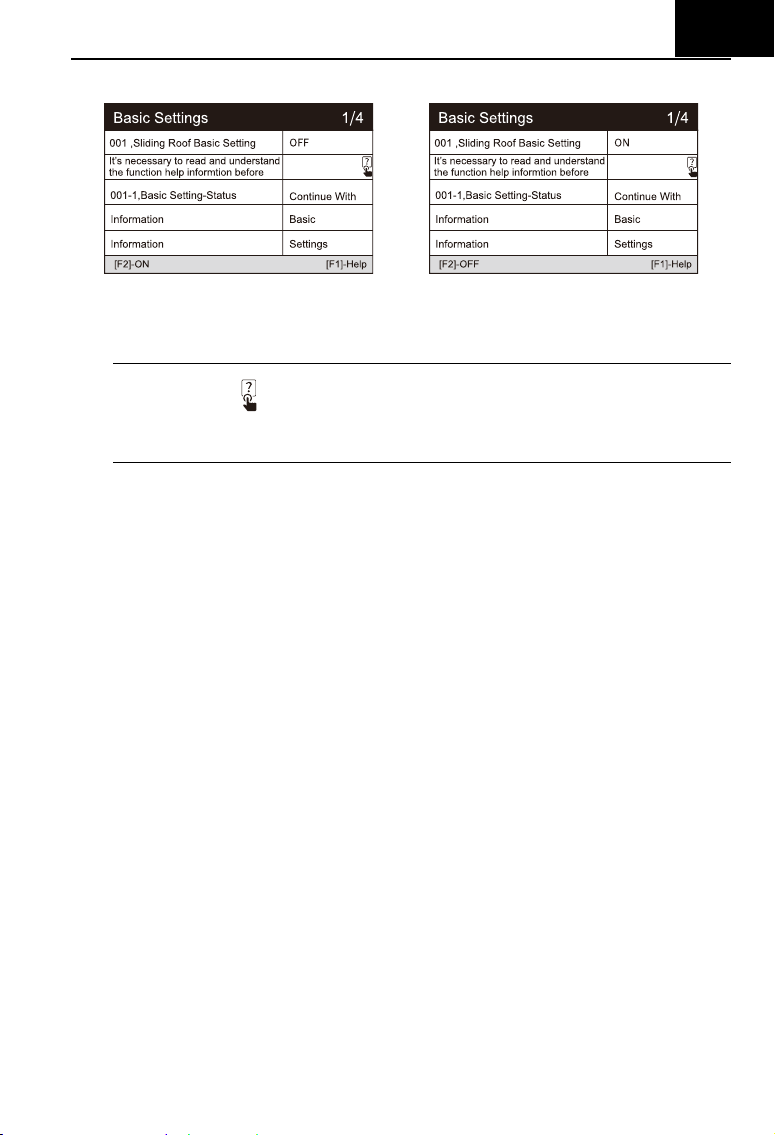
EN
17
value of the automatic sunroof at each position.
5) At this time, various actions of the sunroof will be executed. The
status on the screen changes to “ON”.
Note: marked
means that the information here is pressed [?] button to
see all information.
Activate ESP System / Function Test
After the ABS / ESP has been overhauled or replaced, it is
necessary to carry out the function test to activate the ABS / ESP system,
and at the same time, it is necessary to complete the matching of ABS /
ESP module according to the test procedure.
Brake System Bleeding
When replacing the ABS computer or when the ABS brake oil runs
out, you need to perform this basic adjustment to empty the air in the
brake fluid to ensure the safe and effective operation of the ABS system.
Adaptation --- This function allows you to perform adaptive learning /
reset / calibration and other functions for each control module, and also
includes some important module data for parameter adjustment.
Focus on the following three functions:
Central Locking: Auto-Lock
This setting allows you enable / disable the driving automatic locking
function according to your personal preference (when the vehicle speed
is greater than 15 km/h, all doors will be locked automatically).
To preform Central Locking: Auto-Lock:
1) Access “Adaptation”, select “Central Locking: Auto-Lock”.
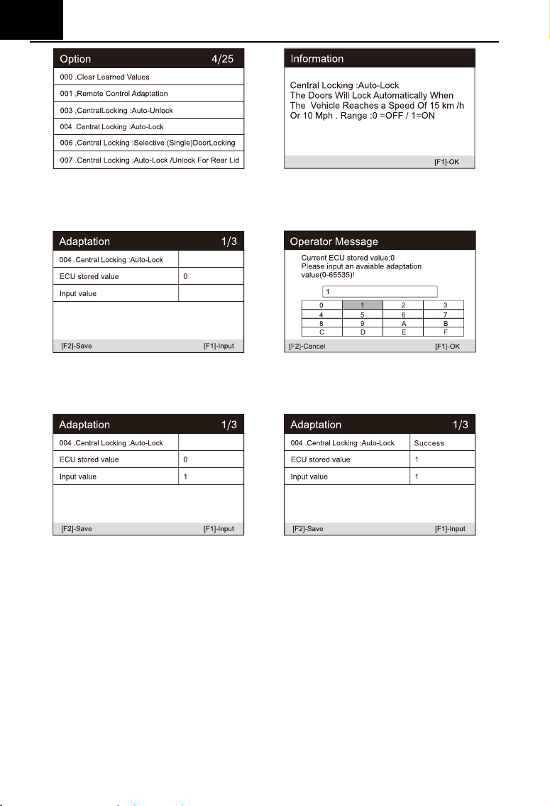
EN
18
2) Read the information on the screen: when the speed reaches
15 km/h, the doors will lock automatically. 0 is off, 1 is on.
3) Input “1”, and press the button [Save]. The status on the screen
changes to “Success”.
Remote Control Adaptation
After clearing all the learned remote control information data
(generally, remote key will be invalid), it is necessary to use this function
to restore the key remote control function.
Central Locking: Audible Locking / Unlocking Confirmation
This setting allows you enable / disable the horn sound feedback
when the vehicle is locked / unlocked.
6.2 Service functions
EN
19
iCarsoft V3.0 Multi-system Car Diagnostic Tool Series provide Oil Reset,
EPB, BMS, DPF, ETC, SAS, Bleeding, Injector and more service functions for
most modern vehicles on the road today. Select Service function from Main
menu to access these special functions. Whether the vehicle has service
function depends on the vehicle brand.
Select the "Service" function to quickly access the vehicle system and
match various special functions. A typical maintenance operation interface
contains a series of menu guided execution commands. Select the
appropriate operation options according to the on-screen instructions, input
the correct values or data, and carry out various necessary operations. By
completing these operations, the system will guide the user to complete
various operation procedures for vehicle maintenance and repair.
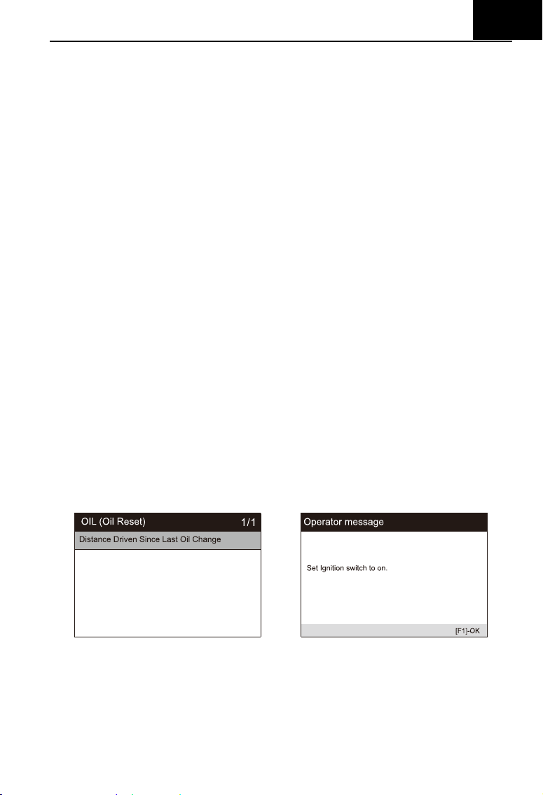
6.2.1 Oil Reset
Select Oil Reset icon in the Main Screen and wait for the vehicle
manufacturer screen. Choose the correct vehicle make.
Different vehicles may have different methods to do the oil maintenance,
generally, oil change is required whenever oil lamp is on and the
recommended maintenance period is reached. The Oil Reset function can
reset the maintenance period and distance and turn off the lamp when you
really change the oil. (Take Benz as a sample).
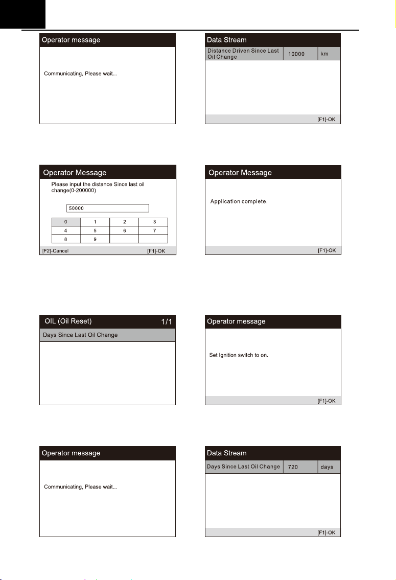
Set the distance driven since last oil change:
1) Select the "Distance driven since last oil change" option in the function
list. Turn on the vehicle ignition.
2) Wait for communication between vehicle and equipment. When the data
stream interface appears, press [OK] to next step.
EN
20
3) Enter the required mileage after oil change and press [OK] to next step
until the application is completed. Press [OK] to exit.
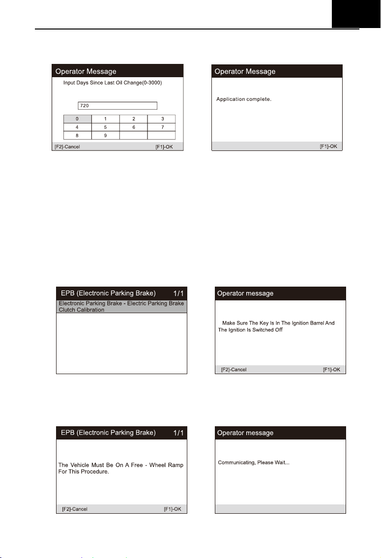
Set the number of days since last oil change:
1) Select the "Days since last oil change" option in the function list. Turn on
the vehicle ignition.
2) Wait for communication between vehicle and equipment. When the
interface of data stream appears, press [OK] to next step.
EN
21
3) Enter the number of days after oil change and press the [OK] to next step
until the application is completed. Press [OK] to exit.
6.2.2 EPB
Electronic Parking Brake (EPB) system maintenance, deactivates and
reactivates the EPB system for replacement and initialization (Take Jaguar as
a sample).
1) Select the "EPB" icon in the service function icon, Select the correct
vehicle according to the on-screen instructions.
2) Select "electronic parking brake - electronic parking brake clutch
calibration" in the function list.
3)
Operate step by step according to the screen, and make the vehicle on
the free ramp as required, and wait for the screen communication to
succeed
.
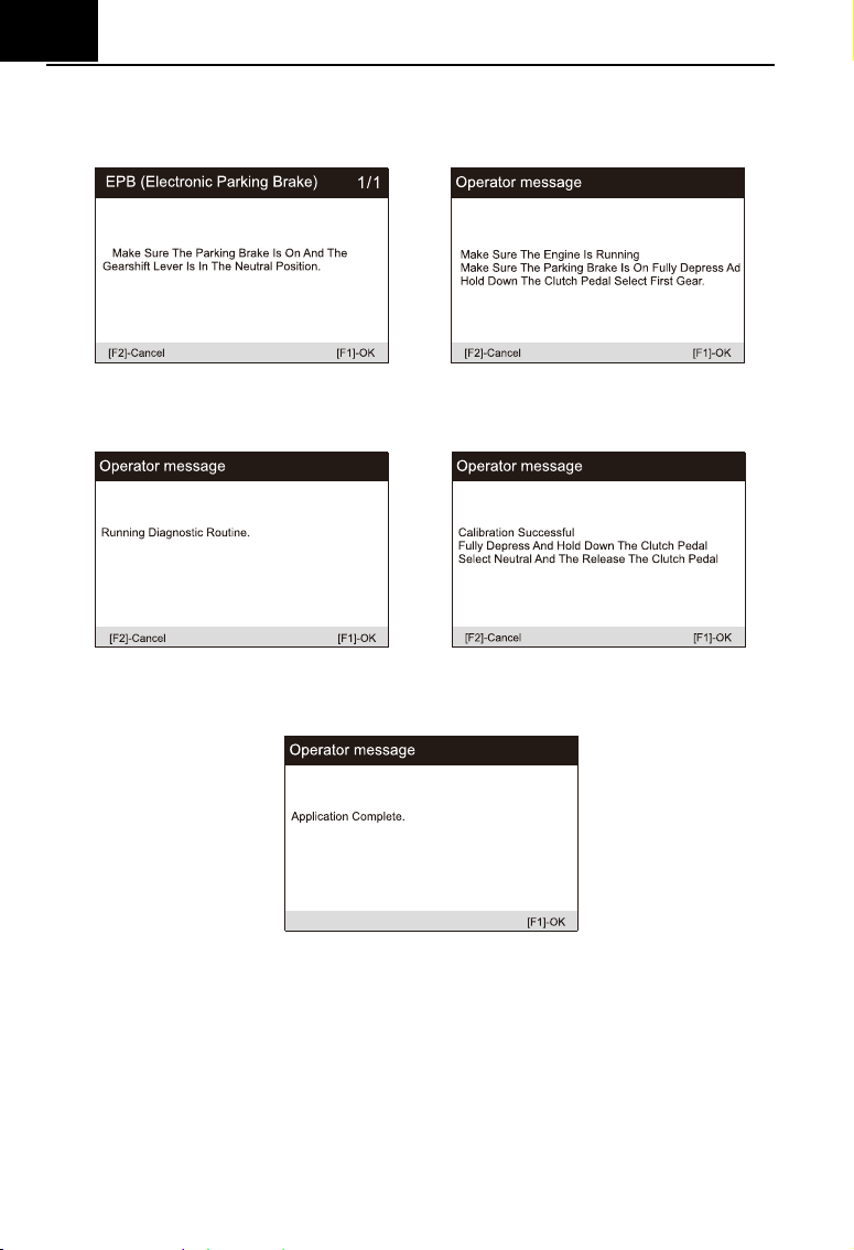
EN
22
4)
As shown in the figure below, make sure that the parking brake is
switched on and the shift lever is in N gear. Operate the clutch as required
when the engine is running
.
5) Press the [OK] to next step until the calibration is successful, fully depress
the clutch pedal, select neutral and release the clutch pedal.
6) The screen prompts that the application is complete, and press [OK] to
exit.
6.2.3 BMS
Battery Management System (BMS), registers new battery to the BMS
while battery replacement (Take LandRover as a sample).
If the vehicle has replaced the battery and needs to replace the battery,
this program will reset the stored internal battery monitoring data.
1) Select the "BMS" icon in the service function icon, Select the correct
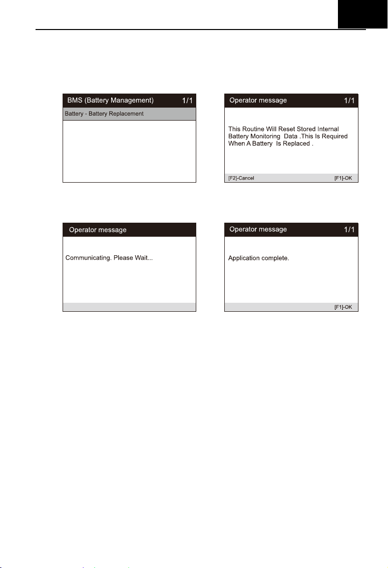
EN
23
vehicle according to the on-screen instructions.
2) Select the "battery - battery replacement" option in the function list, and a
operator message will appear on the screen: this operation will re store
the internal battery monitoring data. Press [OK] to continue.
3) Until the screen prompts the application to complete. The operation is
completed.
4) Press [OK] to exit.
6.2.4 DPF
Diesel Particulate Filter (DPF) regeneration control system, requests the
DPF regeneration process while DPF blockage and turn off the DPF indicator
(Take LandRover as a sample).
1) Select the "DPF" icon in the service function icon, Select the correct
vehicle according to the on-screen instructions.
2) Select the " Powertrain - Diesel Particulate Fitter Dynamic Regeneration"
option in the function list, and carefully read the screen prompts for the
conditions for dynamic regeneration of the diesel particulate filter, And
pay special attention to the need for two people to perform this operation.
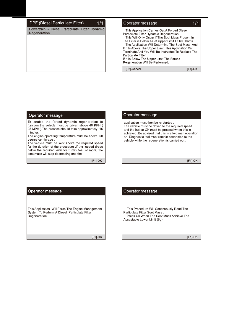
EN
24
3) Follow the instructions on the screen step by step, and start the vehicle to
drive at a speed higher than 40 km for about 15 minutes. Drive the vehicle
to the required speed and press the "OK" button when the speed is
reached.
4) Subsequent procedures will force the engine management system to
perform a diesel particulate filter regeneration.
5) Regeneration is completed when it is indicated that the soot mass in the
particulate filter is now at an acceptable lower limit. At this time, you can
stop and turn off the ignition switch.
EN
25
6) Application completed, press OK to exit.
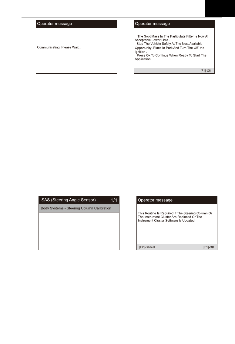
6.2.6 SAS
SAS: Steering Angle Sensor (SAS) calibration, calibrates the steering
wheel to straight ahead, or recalibrates SAS while steering part replacement
(Take Jaguar as a sample).
If the steering column or instrument cluster is replaced or the instrument
cluster software is updated, a body system steering column calibration is
required.
1) Select the "SAS" icon in the service function icon, Select the correct
vehicle according to the on-screen instructions.
2) Select “body system steering column calibration” in the function list and
follow the screen prompts.
3) The screen prompts that you need to input the 3rd to 10th digit tag
numbers, and enter as required.
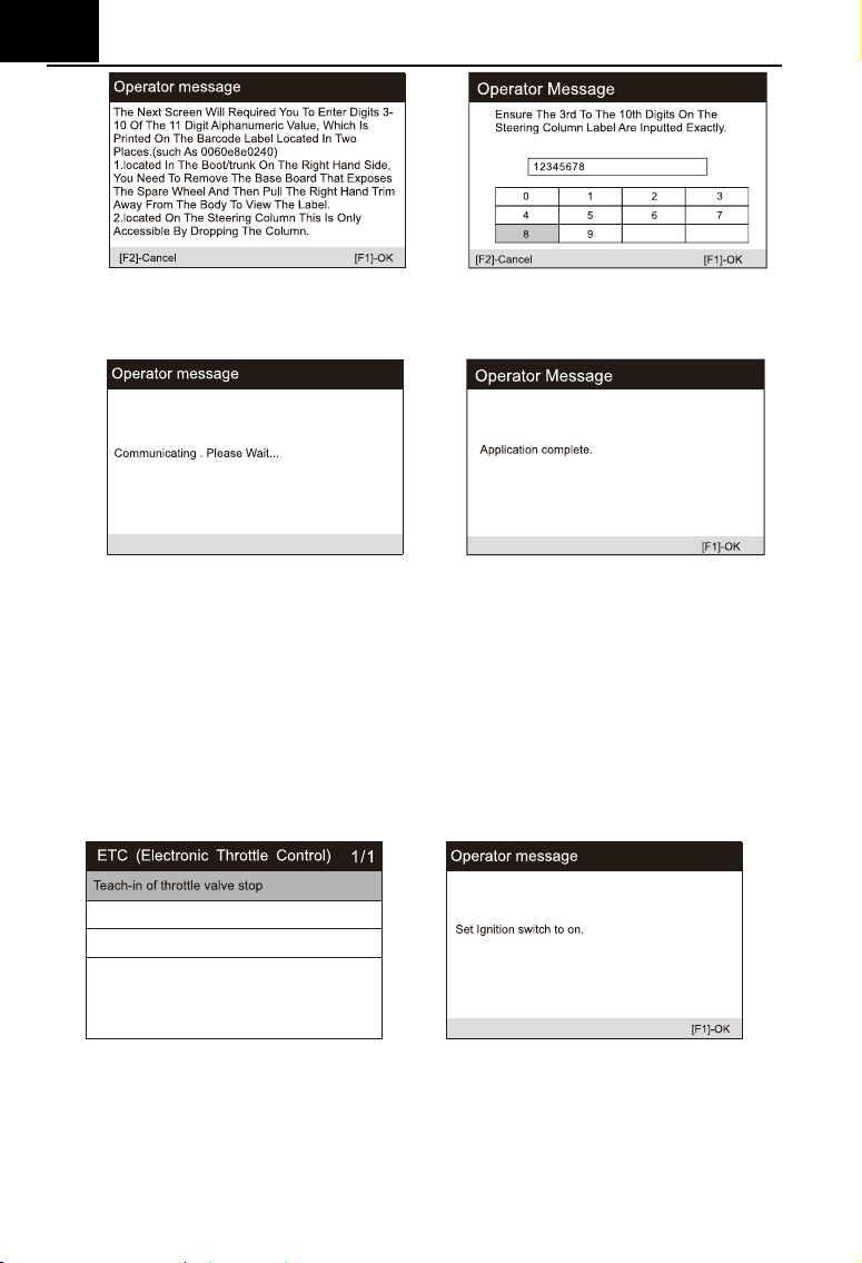
EN
26
4) In the next step of system communication, until the application program is
completed. Press [OK] to exit.
6.2.5 ETC
Electronic Throttle Control system (ETC), relearns the throttle valve
control value while clear or replace the throttle valve (Take Benz as a sample).
1) Select the "ETC" icon in the service function icon, Select the correct
vehicle according to the on-screen instructions.
2) Learn the throttle valve stop point value. Select the "teach in of throttle
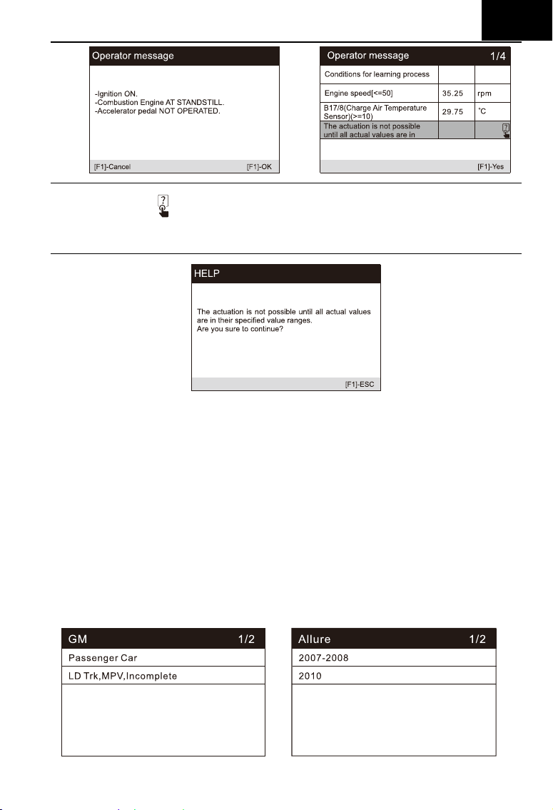
valve stop" option in the function list. Turn on the vehicle ignition.
3) Read the operator information on the screen, press OK to proceed to the
next step, and set the learning parameters as required. You can also
press [?] button to view the help information.
EN
27
Note: marked
means that the information here is pressed [?] button to
see help information. As shown in the figure below:
4) Press the [Yes] button to perform the learning process. Until the
application is complete, press [OK] to exit.
6.2.7 ABS Bleeding
When the ABS contains air, or the ABS computer / ABS pump / brake
master cylinder / brake cylinder / brake line / brake fluid is replaced, the ABS
bleeding function must be performed to bleed the brake system to restore ABS
brake sensitivity (Take GM as a sample).
1) Select the Bleeding option from Service function icon, and select right
options for your vehicle step by step according to each screen that
appears until the vehicle information is identified.
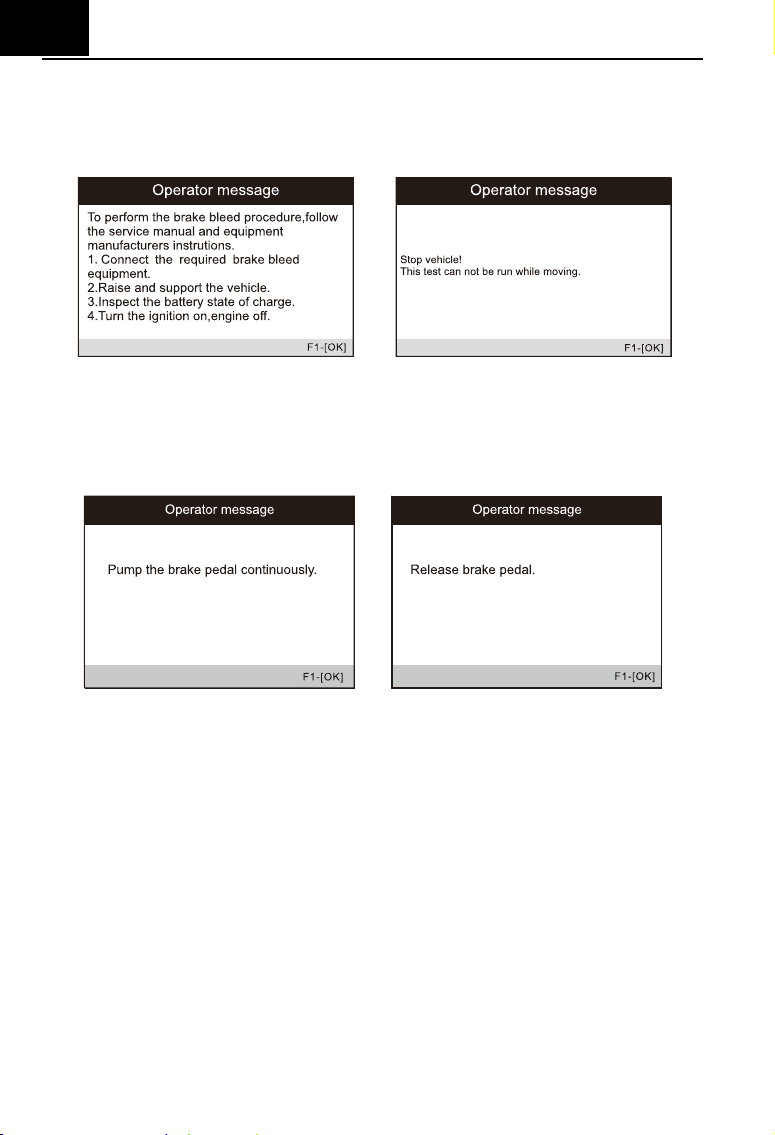
EN
28
2) Turn on the ignition switch and perform the brake exhaust procedure as
required. Carefully read the operator information that appears on the
screen. Note that this function cannot be operated while moving the
vehicle.
3) Turn on the left front exhaust screw as required by the screen and keep
pressing the brake pedal. Follow the instructions on the screen. After a
certain period of time, release the brake pedal and close the front exhaust
screw. The operation is complete.
4) Open the right front exhaust screw as required by the screen, and follow
the same method until the operation is complete.
5) After completing the operation, press [OK] to exit.
6.2.8 Injector
When individual injectors are renewed, the injector control module
requires the new configuration values for the injector to perform correctly.
Write injector actual code or rewrite code in the ECU to the injector code of the
corresponding cylinder so as to more accurately control or correct cylinder
injection quantity, After the ECU or injector is replaced, injector code of each
cylinder must be confirmed or re-coded so that the cylinder can better identify
injectors to accurately control fuel injection. (Take LandRover as a sample).
If the vehicle has replaced the fuel injector, in order to ensure the normal
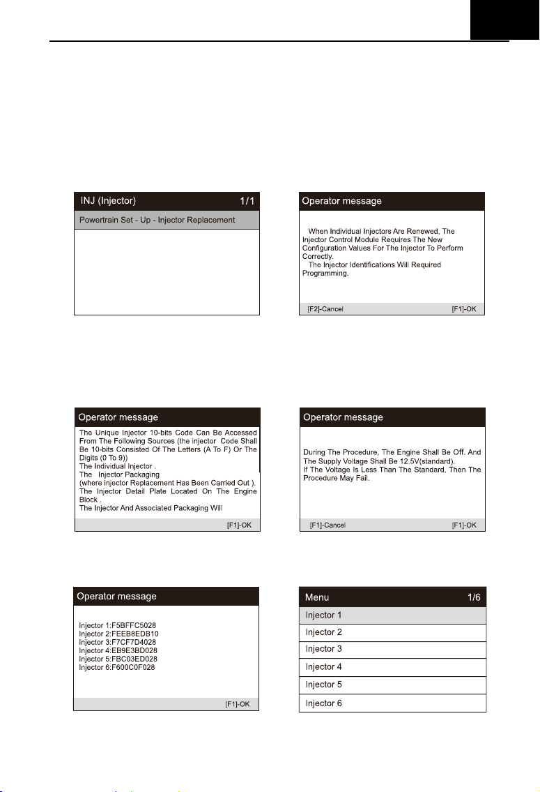
EN
29
operation of the fuel injector, you need to carry out this operation to replace
the fuel injector code.
1) Select the "Injector" icon in the service function icon, Select the correct
vehicle according to the on-screen instructions.
2) Select the "Powertrain Set - Up - Injector Replacement" option in the
function list. The screen indicates that the injector configuration value
needs to be updated.
3) Follow the screen operation step by step, press the [OK] to perform the
next step. In this process, the engine should be shut down, and the power
supply voltage is 12.5V. Pay attention to the prompt of fuel injector code
on the screen.
4) As shown in the figure below, select the serial number of the fuel injector
to be replaced.
5) Read the 10 digit sensor code from the replaced injector, press the [OK]
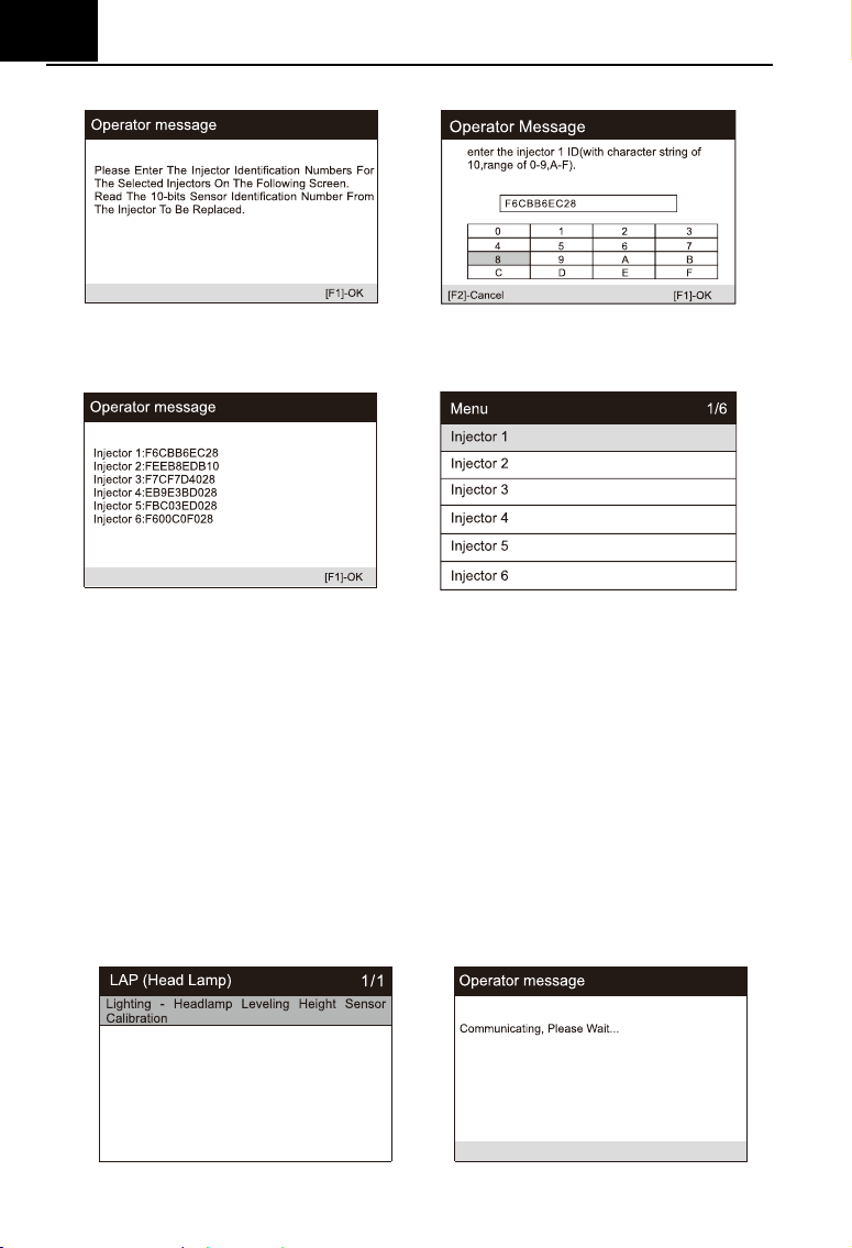
EN
30
to call up the input box and input the identification number.
6) Press [OK] to complete the execution. You can perform the next injector
code change or exit application.
6.2.9 Head Lamp
Head Lamp is about the headlamp maintenance, maintenance and other
related operations (including AFS setting), and then perform this function for
calibration. (Take Jaguar as a sample).
If the vehicle has a headlamp replacement, the calibration of the
headlamp leveling height sensor needs to be performed.
1) Select the "Head Lamp" icon in the service function icon, Select the
correct vehicle according to the on-screen instructions.
2) Select "lighting - headlamp leveling height sensor calibration" in the
function list.
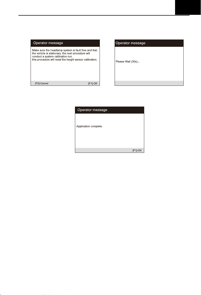
EN
31
3) Wait for the system communication, keep the vehicle stationary as
required, and press [OK] to perform the system calibration operation. This
process takes 30 seconds.
4) Wait until the screen prompts "application completed" to complete the
operation, and press [OK] to exit.
6.2.10 Air Suspension
Air Suspension: After maintenance, replacement and other operations of
the suspension height sensor are performed in all aspects, this function needs
to be executed for suspension learning and calibration. (Take LandRover as a
sample).
There are several function lists in air suspension. Here, select
"suspension system - air suspension inflation" as an example
1) Select the "Air Suspension" icon in the service function icon, Select the
correct vehicle according to the on-screen instructions.
2) Select the "Suspension System - Air Suspension Inflation" option in the
function list.
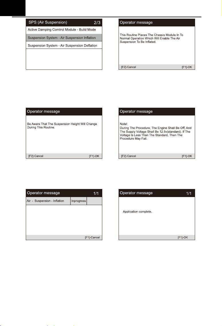
EN
32
3) Carefully read the operation information on the screen, and press the
operation step by step to select the [OK] to continue. Note that in some
processes, the suspension height will change, and the engine should be
turned off, and the power supply voltage is 12.5V.
4) If the conditions are met, the system will enter the communication state,
and the air suspension will enter inflation until the process is completed,
and the system will prompt to turn off the ignition.
6.2.11 TPMS
The TPMS service function include displaying sensor IDs from the
vehicle’s ECU, inputting TPMS sensor replacement IDs and testing
sensors(Take Jaguar as a sample).
Tire pressure sensor replacement:
During this application the wheel unit 8-bits identifications will need to be
entered using the screens provided. The sensor identifications can be
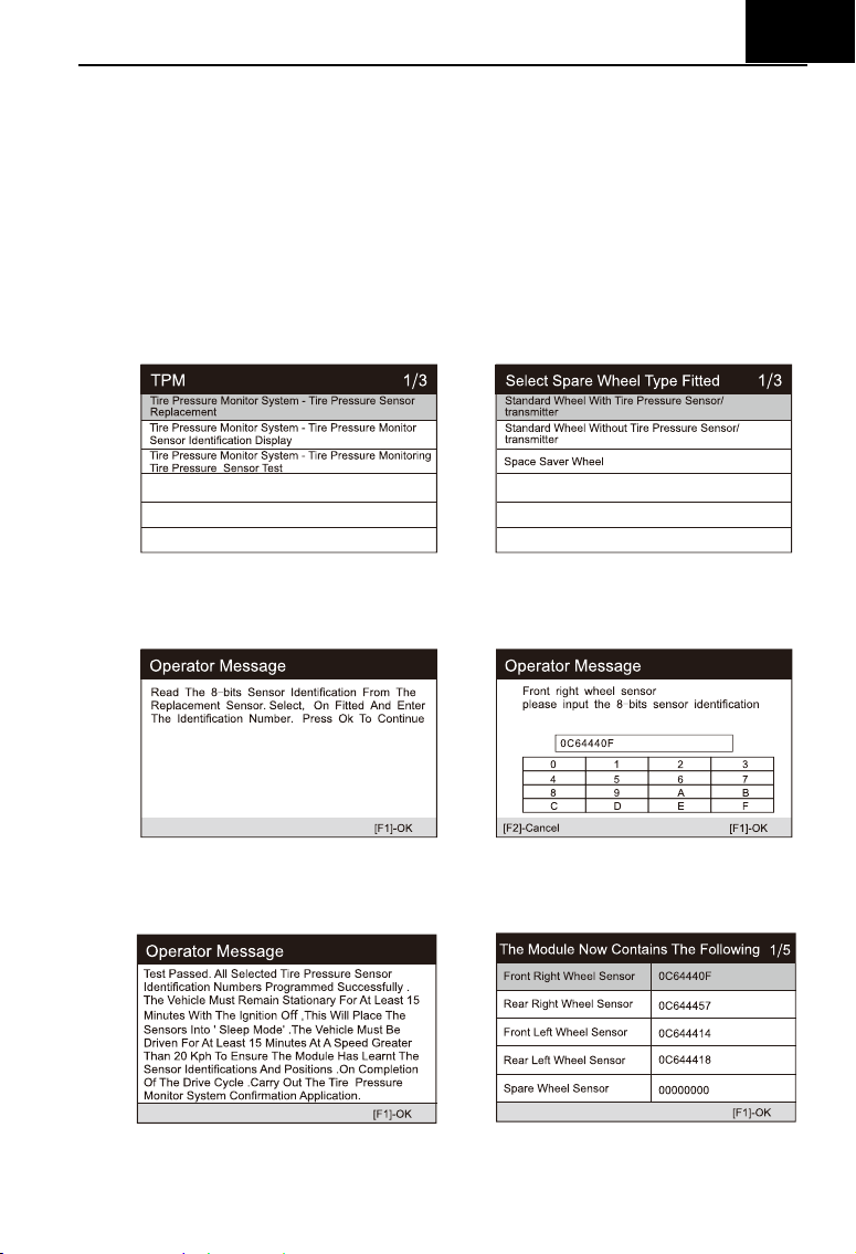
EN
33
accessed by reading directly from the wheel unit or by using the identification
reading tool. On completion, a specific road test will be required followed by
the tire pressure monitor system confirmation application.
1) Select the TPMS icon in the service function icon or the TPM option in
service in diagnostic mode.
Select the correct vehicle according to the
on-screen instructions.
2) Preform tire pressure sensor replacement to go to the next step and
select the standard wheel with tire pressure sensor. Select the right front
wheel sensor according to the screen.
3) Read the operation prompt carefully, input 8-bits Sensor Identifications as
required, and press [OK].
4) After passing the 8-bit sensor identification test, carry out a specific road
test.
6.2.12 Air-conditioner
EN
34
After the refrigerant, blower pump, etc. in the air conditioner are replaced,
the air conditioning system may not work normally. At this time, this function is
needed to activate the air conditioner for a period of time to match the
replaced refrigerant, blower pump and other automotive components. (Take
Benz as a sample).
1) Select the "Air-conditioner" icon in the service function icon, Select the
correct vehicle according to the on-screen instructions.
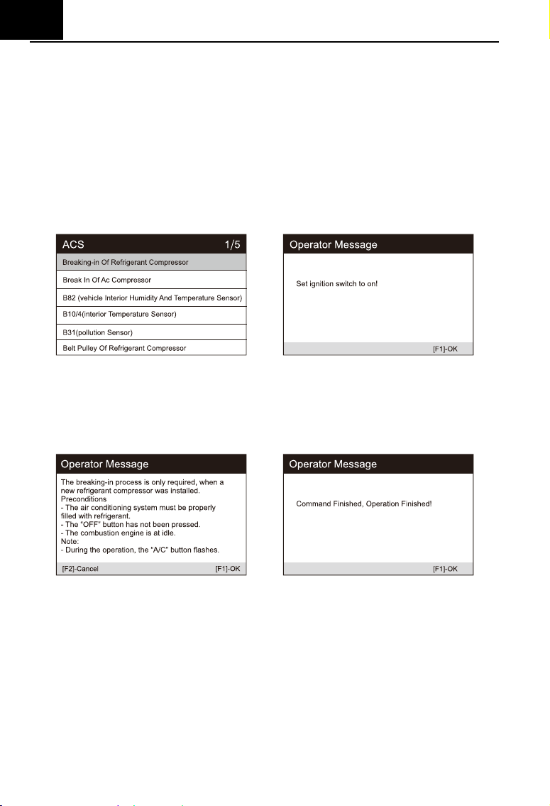
2) When a new refrigerant compressor is installed, the Breaking-in Of
Refrigerant Compressor process is required.
3) Turn on the ignition switch according to the prompt on the screen, and
press OK to display the operation information prompt on the screen.
Continue to press the OK button until the instruction to complete the
operation appears.
4) Press [OK] to exit.
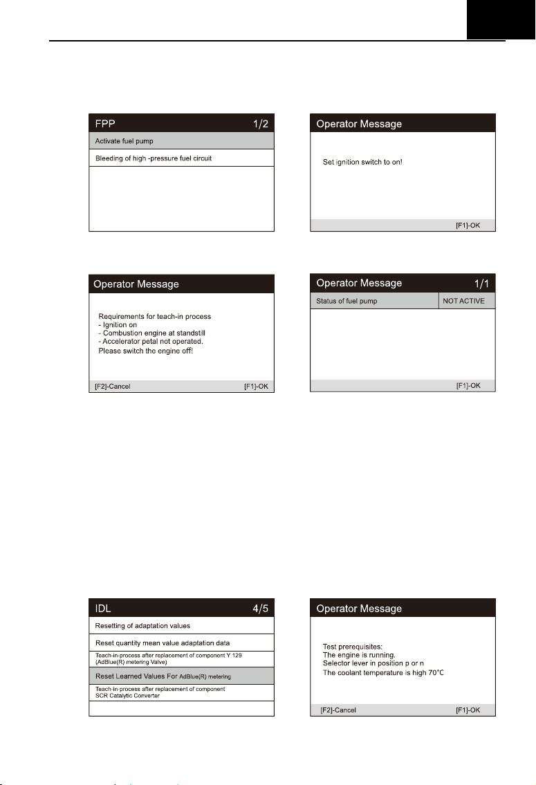
6.2.13 Fuel pump
After the fuel pump is disassembled, repaired or replaced, it may cause
the fuel pump to be unable to continuously provide fuel to the fuel injection
nozzle. At this time, the function needs to be executed to activate the replaced
fuel pump so that the car can start to inject fuel normally and make the engine
achieve the ideal Running status. (Take Benz as a sample).
EN
35
1) Select the "Fuel pump" icon in the service function icon, Select the
correct vehicle according to the on-screen instructions.
2) Select Activate fuel pump.
3) Follow the prompts on the screen until the operation is completed.
4) Press [OK] to exit.
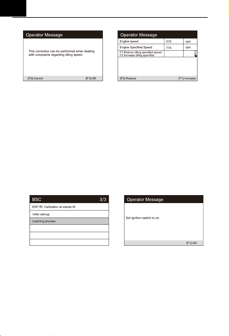
6.2.14 Engine Idle
This correction can be executed when the idle speed fault is resolved.
Adjust the engine speed of the car at idle speed. (Take Benz as a sample).
1) Select the "Engine Idle" icon in the service function icon, Select the
correct vehicle according to the on-screen instructions.
2) Choose to reset the learning value, read the screen prompts, and set the
vehicle as required.
EN
36
3) Press the [reduce] or [increase] button to adjust the engine idle speed.
4) Follow the prompts on the screen until the operation is completed.
5) Press [OK] to exit.
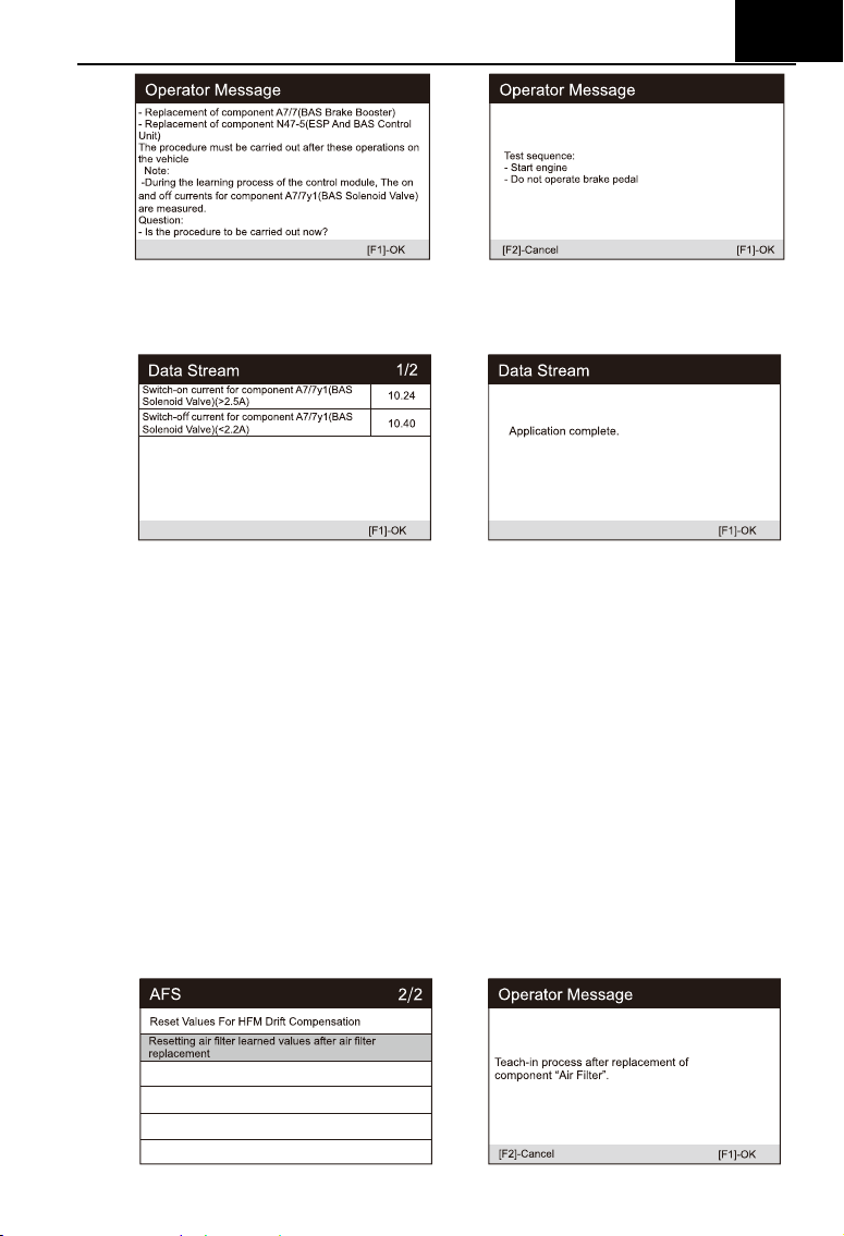
6.2.15 Body stability
Learning and calibration after replacing the body stability control unit and
other related components, such as: lateral acceleration sensor for active roll
stabilization system, BAS brake assist system, ESP electronic stability
program, calibration of yaw rate / lateral and longitudinal acceleration sensors,
pedal angle Sensors, etc. (Take Benz as a sample).
1) Select the "Body stability" icon in the service function icon, Select the
correct vehicle according to the on-screen instructions.
2) Select the learning process and turn on ignition.
3) Carefully read the prompt information on the screen. Before performing
this operation, complete the BAS brake assist system, and replace the
ESP and BAS press units and other components.
EN
37
4) Press [OK] to the next step, this process takes a long time, until the
completed instruction is prompted.
5) Press [OK] to exit.
6.2.16 Air Filter
The engine is a very precise machine part, and even the smallest
impurities will cause the wear of the engine. Therefore, the air must be filtered
by the air cleaner before entering the cylinder. Therefore, the disassembly,
maintenance or replacement of the air filter will cause some particulate
impurities in the air to enter the car parts. At this time, the air filter learning and
matching functions need to be performed to make the air filter work normally.
(Take Benz as a sample).
1) Select the "A / F Setting" icon in the service function icon, Select the
correct vehicle according to the on-screen instructions.
2) Perform resetting the air filter learning value.
EN
38
3) Follow the prompts Until the instruction to complete the command
operation appears.
4) Press [OK] to exit.
6.2.17 Door
After repairing or replacing the window lift motor, it is necessary to
perform relevant functions for calibration (Take Jaguar as a sample).
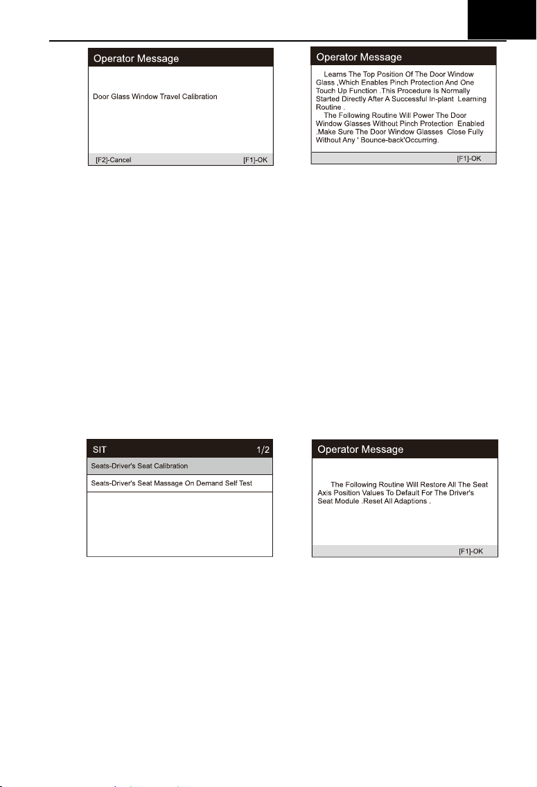
Door Window Calibration:
This routine learns the top position of the door window glass, which
enables pinch protection and one touch up function. The door window glass
position can be learned by executing this routine.
1) Select the "door" icon in the service function icon, Select the correct
vehicle according to the on-screen instructions.
2) Calibrate the drive’s doors and windows.
3) The position of the window glass can be learned by performing this
routine.
EN
39
4) Until the screen prompts that the operation is completed, press the OK to
exit.
6.2.18 Seat
After repairing or replacing the seat position drive motor, it is necessary to
perform relevant functions for calibration (Take Jaguar as a sample).
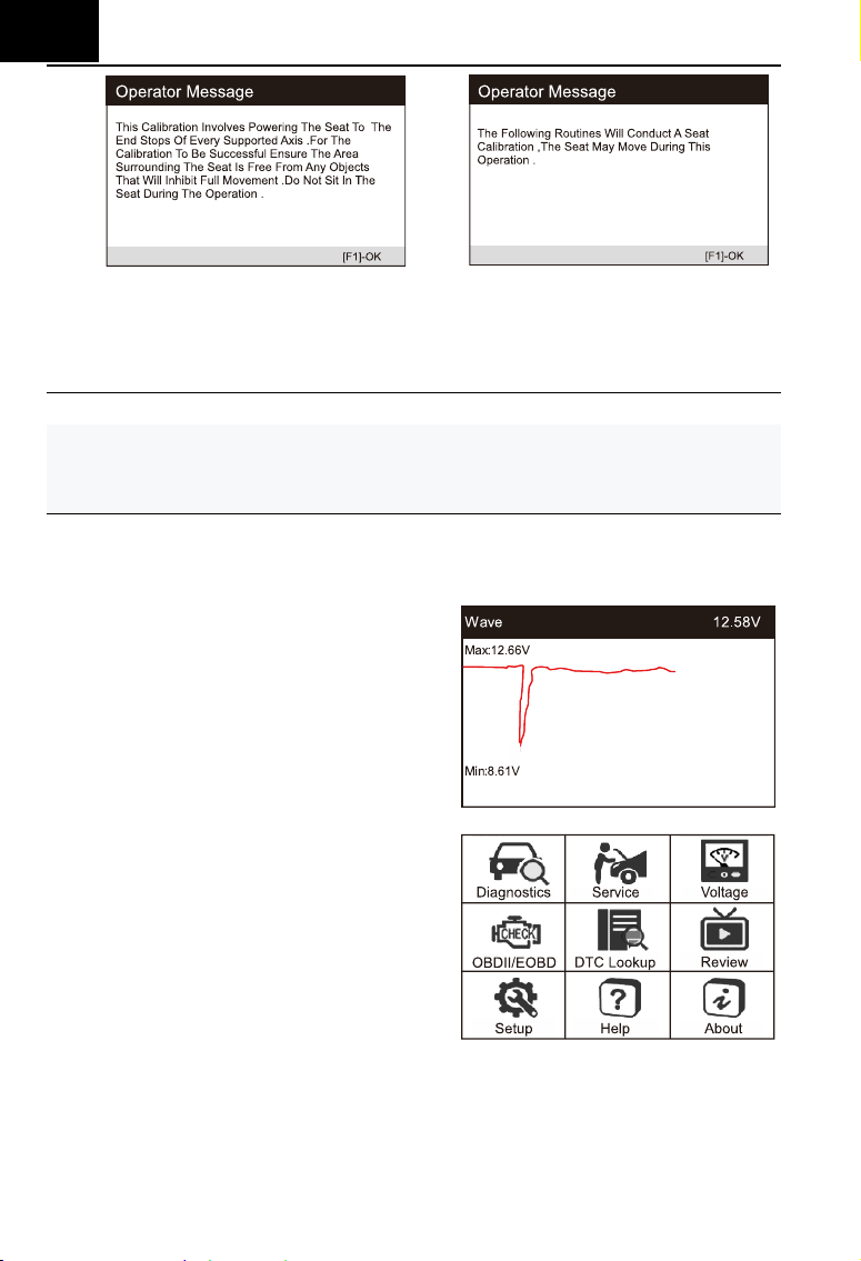
Driver's Seat Calibration:
The following routine will restore all the seat axis position values to
default for the driver's seat module.
1) Select "Seat" icon in service function icon, Select the correct vehicle
according to the on-screen instructions.
2) Calibrate the driver's seat.
3) The program will restore all seat axis position values of the driver's seat
module to the default values. Reset all adaptive values.
4) Make sure that the area around the seat is free of any objects that will
hinder full movement and do not sit on the seat during operation.
EN
40
Passenger's Seat Calibration:
The following routine will restore all the seat axis position values to
default for the passenger seat module.
Note:
Different models will have different menu modes. This manual is for reference.
Everything in kind shall prevail. If there is any increase or decrease in the
function of the product, the actual product shall prevail.
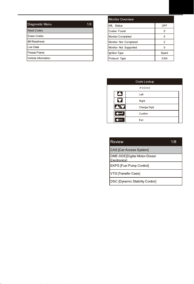
6.3 Battery Voltage Test
On battery voltage page, it shows
the voltage of Data Link Connector (DLC),
which is approximately the vehicle
battery’s status. Especially, it can
observe the voltage while engine start.
6.4 OBDII / EOBD
User cursor button to select the
OBDII / EOBD icon from the main screen,
press ENTER. On Monitor Overview,
press ENTER to the Diagnostic Menu. It
supports all 10 modes of OBDII / EOBD,
such as read current fault code, read
pending fault code, read permanent fault
code, erase fault code, read live data, read freeze frame, read vehicle
information, read IM readiness, read oxygen sensor data, read on-board
monitor data and trigger evaporation system leakage test.
EN
41
6.5 DTC Lookup
Use cursor button to select DTC
Lookup icon from the main screen,
press ENTER. Press LEFT / RIGHT
button to move the highlight bar to
different position. Press UP / DOWN
button to alter the value, and press
ENTER button, the screen will display
definition of the DTC.
6.6 Review and Report
Use the cursor button to select the
Review icon from the main screen, press
ENTER to review data. The saved data
also can be uploaded to PC by data
cable and create report document on
PC.
6.7 Setup
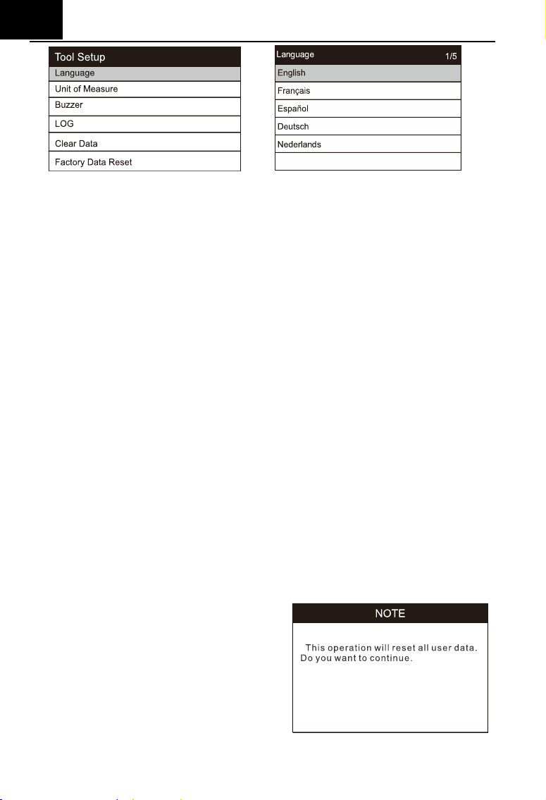
6.7.1 Language
Use cursor button to select Setup icon on the main screen, press ENTER.
Select Language and press ENTER to set the language.
EN
42
6.7.2 Unit of Measure
On Tool Setup, use DOWN button to select Unit of Measure and press
ENTER, where you can choose Metric or Imperial.
6.7.3 Buzzer
On Tool Setup, use DOWN button to select Buzzer and press ENTER,
where you can turn the buzzer ON or OFF.
6.7.4 LOG
On Tool Setup, use DOWN button to select Log and press ENTER, where
you can turn the Log ON or OFF.
Set to ON, the log function is enable. RECORD function will be disable.
The log function will be disable after reboot.
The log function is used to feed-back data to manufacturer,
the log file will be saved to the path MSDIAG / LOG / on memory card.
6.7.5 Clear Data
On Tool Setup, use Down button to select clear data and press ENTER.
You can clear the saved logs or clear the saved records.
6.7.6 Factory Data Reset
On Tool Setup, use Down button to
select Factory Data Reset and press
ENTER, where you can get a note “This
operation will reset all user data. Do you
want to continue”. You can choose yes or
no.
EN
43
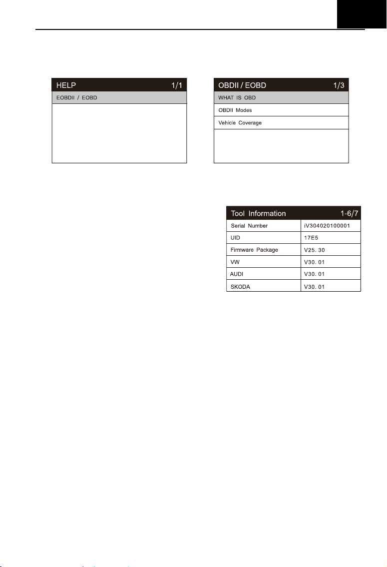
6.8 Help
Use cursor button to select Help icon on the main screen, press ENTER.
6.9 About
Use cursor button to select About icon
on the main screen, press ENTER. On the
Tool Information page, there are software
version, hardware version and product
serial number etc..
7 Warranty
7.1 Limited One Year Warranty
iCarsoft warrants to its customers that this product will be free from all
defects in materials and workmanship for a period of one year from the data of
the original purchase, subject to the following terms and conditions:
1) The sole responsibility of iCarsoft under the warranty is limited to either the
repair or, at the option of iCarsoft , replacement of the Diagnostic Tool at no
charge with Proof of Purchase. The sales receipt may be used for this
purpose.
2) This warranty does not apply to damages caused by improper use,
accident, flood, lightning, of if the product was altered or repaired by
anyone other than the manufacturer’s Service Center.
3) iCarsoft shall not be liable for any incidental or consequential damages
arising from the use, misuse, or mounting of the Diagnostic Tool. Some
states don’t allow limitations on how long an implied warranty lasts, so the

EN
44
above limitations may not apply to you.
7.2 Service Procedures
If you have any questions, please contact your local store, distributor or
visit our website
www.icarsoft.us / www.icarsoft.com .If it becomes necessary
to return the Diagnostic Tool for repair, contact your local distributor for more
information.
8 Software Update&Data Print
Software Update allows you to update the scanner’s software through a
PC / laptop (With Windows Operation System). Pls prepare a computer that
can access to the Internet and connect the scanner to the computer via data
cable. And the install the iCarsoft_MSDIAG_PCClientKits and run it.
The data print function allows you to print out the DTC data, Module
Information, Live Data and VIN recorded by the scanner when connecting the
scanner to a PC / laptop with data cable supplied.
Note:
The Software Update and Data Print functions share with the same application
which named iCarsoft_MSDIAG_PCClientKits.
8.1 Update Procedures:
1) Download the iCarsoft_MSDIAG_PCClientKits.exe package from
http://www.icarsoft.us or from your dealer.
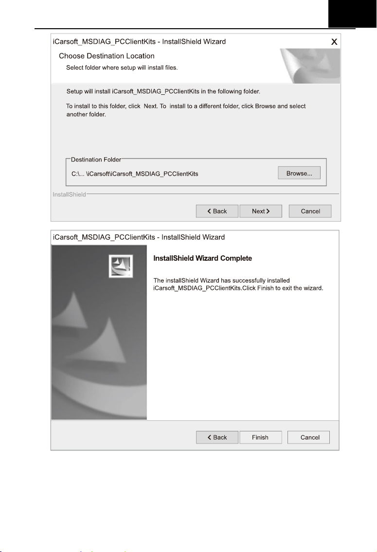
2) Run the installation package, just click [Next] button all the way, and finish
the installation.
EN
45
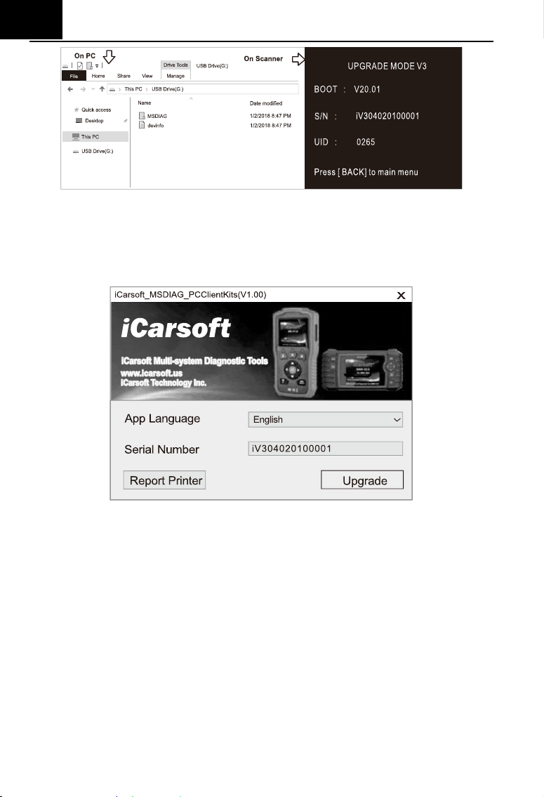
3) Connect PC / Laptop
Connect the scanner to PC via data cable (if you have a TF card reader,
you can also update via TF card reader),PC will recognize one more
removable U-disc.
EN
46
4) Start application
Run the application iCarsoft_MSDIAG_PCClientkits on your PC, the
application will recognize the scanner by SN.
5) Upgrade
Press Download button to start software upgrade, when the update
process is completed, it will come up with an update successful message.
EN
47
8.2 Data Print Procedures:
1) Save data
User can press [RECORD] button to save the diagnosis data such as
Module Information, Live Data, Fault, Data, Freeze Frame and Vehicle
Information etc., the data will be saved as *.rex file on the TF memory card,
these files can be used to create diagnosis report by the application
iCarsoft_MSDIAG_PCClientKits.
2) Supposed the application iCarsoft_MSDIAG_PCClientKits has already
being installed correctly, If NOT, please refer to above” Update
Procedures”.
3) Launch Report-Printers
Press the button [Report Printer] to launch Report-Printer center.
EN
48
4) Select files
BMW_EN_TEST_0001 shows all recorded data with BMW Diagnosis
Software.
OBD_EN_TEST_0001 shows all recorded data with OBD Diagnosis
Software.
Click the *.rex to add the data to edit box
EN
49
[CLEAR] button to clear all data in the edit area.
[SAVE] button to save all data in the edit area as a text file.
[PREVIEW] button for printer-preview.
[PRINT] button to print all data in the edit area.