Loading ...
Loading ...
Loading ...
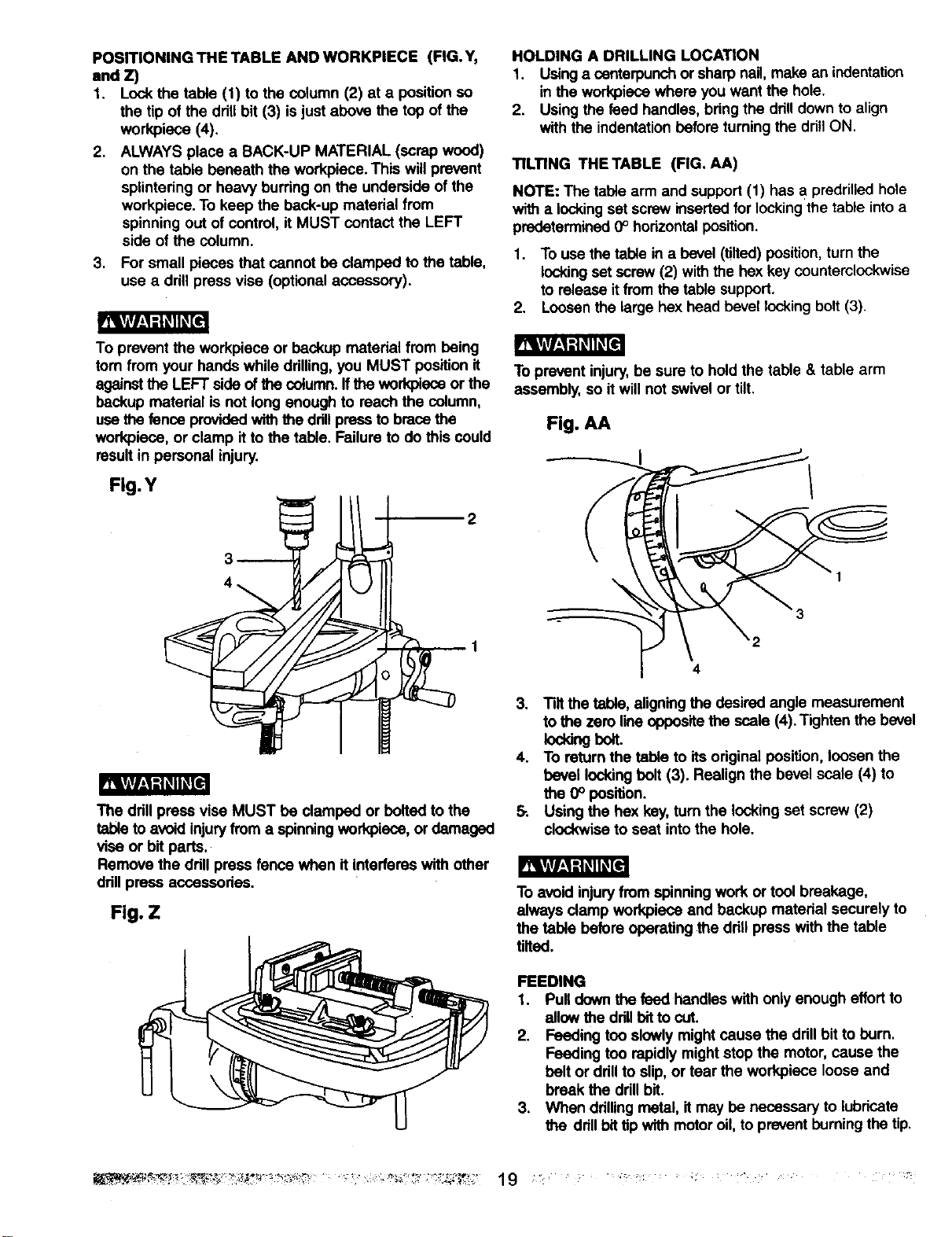
POSITIONING THE TABLE ANDWORKPIECE (FIG.Y,
and Z)
1. Lock the table (I) to the column (2) at a position so
the tip of the drill bit (3) is just above the top of the
workpiece (4).
2. ALWAYS place a SACK-UP MATERIAL (scrap wood)
on the table beneath the workpiece. This willprevent
splintering or heavy burring on the underside ofthe
workpiece. To keep the beck-up material from
spinning out of control, it MUST contact the LEFT
side of the column.
3. For small pieces that cannot be clamped to the table,
use a drill press vise (optional accessory).
fRgf/_qK_
To prevent the workpiece or beckup material from being
tom from your hands while drilling,you MUST position it
againstthe LEFT side ofthe column,ffthe workpisce or the
beckup matedal is not long enough to reach the column,
usethe fence providedwith the ddUpress to brace the
workpiece, or clamp it to the table. Failure to do this could
resultin personal injury.
Fig.Y
R_gf/i1_Kqi_e
The drillpress vise MUST be clamped or bolted to the
table to avoidinjuryfrom a spinningworkpiece, or damaged
vise or bit parts.
Remove the ddll press fence when it interferes with other
drillpress accessories.
Fig. Z
HOLDING A DRILLING LOCATION
1. Usinga centerpunch or sharp nail, make an indentation
in the workpiece where you want the hole.
2. Using the feed handles, bang the ddll downto align
withthe indentationbefore turning the drillON,
TILTING THETABLE (FIG. AA)
NOTE: The table arm and support(1) has a predrilled hole
with a locking set screw inserted for lockingthe table intoa
predetermined0° horizontalposition.
1. To use the table in a bevel (tilted) position,turn the
lockingset screw (2) with the hex key counterclockwise
to release it fromthe table support.
2. Loosen the large hex head bevel locking bolt (3).
To prevent injury,be sure to hold the table & table arm
assembly, so it will not swivel or tilt.
Fig. AA
3
2
4
3. Tiltthe table, aligningthe desired angle measurement
to the zero lineoppositethe ,scale(4).Tighten the bevel
lockingbolt.
4. To return the table to its original position, loosen the
bevel lockingbolt (3). Realign the bevel scale (4) to
the 0° position.
& Using the hex key, turn the lockingset screw (2)
clockwise to seat intothe hole.
To avoid injuryfrom spinningwork or tool breakage,
always clamp workpieco end backup material securely to
the table before operating the ddUpress with the table
tilted.
FEEDING
1. Pull downthe feed handles with only enough effort to
allow the ddll bitto cut.
2. Feeding too slowlymight cause the drill bit to burn.
Feeding too rapidly mightstop the motor, cause the
belt or ddll to slip, or tear the workpiece loose and
break the ddll bit.
3, When ddllingmetal, it may be necessary to lubricate
ttm drillbittip with motoroil, to prevent burningthe tip.
Loading ...
Loading ...
Loading ...