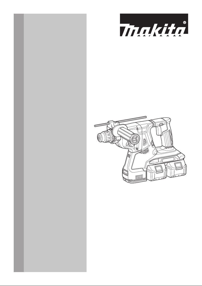
INSTRUCTION MANUAL
MANUAL DE INSTRUCCIONES
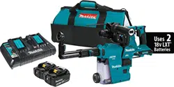
Cordless Combination Hammer
Martillo Rotativo Combinado
Inalámbrico
XRH08
XRH10
XRH11
IMPORTANT: Read Before Using.
IMPORTANTE: Lea antes de usar.

2 ENGLISH
ENGLISH (Original instructions)
SPECIFICATIONS
Model: XRH08 XRH10 XRH11
Capacities Concrete 28 mm (1-1/8")
Core bit 54 mm (2-1/8")
Diamond core bit (dry type) 65 mm (2-9/16")
Steel 13 mm (1/2")
Wood 32 mm (1-1/4")
No load speed 0 - 980/min
Blows per minute 0 - 5,000/min
Overall length 373 mm (14-3/4") 404 mm (15-7/8")
Rated voltage D.C. 36 V
Net weight 3.9 - 5.1 kg (8.6 - 11.2 lbs)
Optional accessory
Model: DX03 (For XRH08/XRH10) DX04 (For XRH11)
Suction performance 350 l/min
Operating stroke Up to 190 mm (7-1/2")
Suitable drill bit Up to 260 mm (10-1/4")
Rated voltage D.C. 18 V
Net weight 1.4 kg (3.2 lbs) 1.5 kg (3.2 lbs)
• Duetoourcontinuingprogramofresearchanddevelopment,thespecicationshereinaresubjecttochange
without notice.
• Specicationsandbatterycartridgemaydifferfromcountrytocountry.
• Theweightmaydifferdependingontheattachment(s),includingthebatterycartridge.Thelightestandheavi-
estcombination,accordingtoEPTA-Procedure01/2014,areshowninthetable.
Applicable battery cartridge
BL1815N / BL1820B / BL1830 / BL1830B / BL1840B / BL1850B / BL1860B
• Someofthebatterycartridgeslistedabovemaynotbeavailabledependingonyourregionofresidence.
WARNING: Only use the battery cartridges listed above. Use of any other battery cartridges may cause
injuryand/orre.
SAFETY WARNINGS
General power tool safety warnings
WARNING:
Read all safety warnings, instruc-
tions, illustrations and specications provided with this
power tool. Failure to follow all instructions listed below
mayresultinelectricshock,reand/orseriousinjury.
Save all warnings and instruc-
tions for future reference.
Theterm"powertool"inthewarningsreferstoyour
mains-operated(corded)powertoolorBATTERY-
operated (cordless) power tool.
Work area safety
1. Keep work area clean and well lit. Cluttered or
dark areas invite accidents.
2. Do not operate power tools in explosive atmo-
spheres, such as in the presence of ammable
liquids, gases or dust. Power tools create sparks
which may ignite the dust or fumes.
3. Keep children and bystanders away while
operating a power tool. Distractions can cause
you to lose control.
Electrical Safety
1. Power tool plugs must match the outlet. Never
modify the plug in any way. Do not use any
adapter plugs with earthed (grounded) power
tools. Unmodiedplugsandmatchingoutletswill
reduce risk of electric shock.
2. Avoid body contact with earthed or grounded
surfaces, such as pipes, radiators, ranges and
refrigerators.Thereisanincreasedriskofelec-
tric shock if your body is earthed or grounded.
3. Do not expose power tools to rain or wet con-
ditions. Water entering a power tool will increase
the risk of electric shock.

3 ENGLISH
4. Do not abuse the cord. Never use the cord for
carrying, pulling or unplugging the power tool.
Keep cord away from heat, oil, sharp edges
or moving parts. Damaged or entangled cords
increase the risk of electric shock.
5. When operating a power tool outdoors, use an
extension cord suitable for outdoor use. Use of
a cord suitable for outdoor use reduces the risk of
electric shock.
6. If operating a power tool in a damp location is
unavoidable, use a ground fault circuit inter-
rupter (GFCI) protected supply. Use of a GFCI
reduces the risk of electric shock.
7. Power tools can produce electromagnetic
elds (EMF) that are not harmful to the user.
However, users of pacemakers and other similar
medical devices should contact the maker of their
device and/or doctor for advice before operating
this power tool.
Personal Safety
1. Stay alert, watch what you are doing and use
common sense when operating a power tool.
Do not use a power tool while you are tired or
under the inuence of drugs, alcohol or med-
ication.Amomentofinattentionwhileoperating
powertoolsmayresultinseriouspersonalinjury.
2. Use personal protective equipment. Always
wear eye protection. Protective equipment such
as dust mask, non-skid safety shoes, hard hat, or
hearing protection used for appropriate conditions
willreducepersonalinjuries.
3. Prevent unintentional starting. Ensure the
switch is in the off-position before connecting
to power source and/or BATTERY pack, pick-
ing up or carrying the tool. Carrying power tools
withyourngerontheswitchorenergisingpower
tools that have the switch on invites accidents.
4. Remove any adjusting key or wrench before
turning the power tool on.Awrenchorakeyleft
attached to a rotating part of the power tool may
resultinpersonalinjury.
5. Do not overreach. Keep proper footing and
balance at all times.Thisenablesbettercontrol
of the power tool in unexpected situations.
6. Dress properly. Do not wear loose clothing or
jewellery. Keep your hair, clothing and gloves
away from moving parts.Looseclothes,jewel-
lery or long hair can be caught in moving parts.
7. If devices are provided for the connection of
dust extraction and collection facilities, ensure
these are connected and properly used. Use of
dust collection can reduce dust-related hazards.
8. Do not let familiarity gained from frequent use
of tools allow you to become complacent and
ignore tool safety principles.Acarelessaction
cancausesevereinjurywithinafractionofa
second.
9. Always wear protective goggles to protect
your eyes from injury when using power tools.
The goggles must comply with ANSI Z87.1 in
the USA.
It is an employer's responsibility to enforce
the use of appropriate safety protective equip-
ments by the tool operators and by other per-
sons in the immediate working area.
Power tool use and care
1. Do not force the power tool. Use the correct
power tool for your application.Thecorrect
powertoolwilldothejobbetterandsaferatthe
rate for which it was designed.
2. Do not use the power tool if the switch does
not turn it on and off.Anypowertoolthatcannot
be controlled with the switch is dangerous and
must be repaired.
3.
Disconnect the plug from the power source and/
or remove the BATTERY pack, if detachable,
from the power tool before making any adjust-
ments, changing accessories, or storing power
tools. Such preventive safety measures reduce the
risk of starting the power tool accidentally.
4. Store idle power tools out of the reach of chil-
dren and do not allow persons unfamiliar with
the power tool or these instructions to operate
the power tool. Power tools are dangerous in the
hands of untrained users.
5. Maintain power tools and accessories. Check
for misalignment or binding of moving parts,
breakage of parts and any other condition that
may affect the power tool’s operation. If dam-
aged, have the power tool repaired before use.
Many accidents are caused by poorly maintained
power tools.
6. Keep cutting tools sharp and clean. Properly
maintained cutting tools with sharp cutting edges
are less likely to bind and are easier to control.
7. Use the power tool, accessories and tool bits
etc. in accordance with these instructions, tak-
ing into account the working conditions and
the work to be performed. Use of the power tool
for operations different from those intended could
result in a hazardous situation.
8. Keep handles and grasping surfaces dry,
clean and free from oil and grease. Slippery
handles and grasping surfaces do not allow for
safe handling and control of the tool in unexpected
situations.
9. When using the tool, do not wear cloth work
gloves which may be entangled.Theentangle-
ment of cloth work gloves in the moving parts may
resultinpersonalinjury.
BATTERY tool use and care
1. Recharge only with the charger specied by
the manufacturer.Achargerthatissuitablefor
onetypeofBATTERYpackmaycreateariskof
rewhenusedwithanotherBATTERYpack.
2.
Use power tools only with specically des-
ignated BATTERY packs. Use of any other
BATTERYpacksmaycreateariskofinjuryandre.
3.
When BATTERY pack is not in use, keep it
away from other metal objects, like paper clips,
coins, keys, nails, screws or other small metal
objects, that can make a connection from one
terminal to another.ShortingtheBATTERYtermi-
nalstogethermaycauseburnsorare.
4. Under abusive conditions, liquid may be
ejected from the BATTERY; avoid contact. If
contact accidentally occurs, ush with water.
If liquid contacts eyes, additionally seek med-
ical help.LiquidejectedfromtheBATTERYmay
cause irritation or burns.
4 ENGLISH
5. Do not use a BATTERY pack or tool that is
damaged or modied.Damagedormodied
batteries may exhibit unpredictable behaviour
resultinginre,EXPLOSIONorriskofinjury.
6. Do not expose a BATTERY pack or tool to re
or excessive temperature.Exposuretoreor
temperature above 130 °C may cause explosion.
7. Follow all charging instructions and do not
charge the BATTERY pack or tool outside the
temperature range specied in the instruc-
tions. Charging improperly or at temperatures
outsidethespeciedrangemaydamagethe
BATTERYandincreasetheriskofre.
Service
1. Have your power tool serviced by a qualied
repair person using only identical replacement
parts.Thiswillensurethatthesafetyofthepower
tool is maintained.
2.
Never service damaged BATTERY packs. Service
ofBATTERYpacksshouldonlybeperformedbythe
manufacturer or authorized service providers.
3. Follow instruction for lubricating and chang-
ing accessories.
4. Do not modify or attempt to repair the appli-
ance or the BATTERY pack except as indicated
in the instructions for use and care.
CORDLESS ROTARY HAMMER
SAFETY WARNINGS
1. Wear ear protectors. Exposure to noise can
cause hearing loss.
2. Use auxiliary handle(s), if supplied with the
tool.Lossofcontrolcancausepersonalinjury.
3.
Hold power tool by insulated gripping sur-
faces, when performing an operation where the
cutting accessory may contact hidden wiring.
Cutting accessory contacting a "live" wire may
make exposed metal parts of the power tool "live"
and could give the operator an electric shock.
4.
Wear a hard hat (safety helmet), safety glasses and/
or face shield. Ordinary eye or sun glasses are NOT
safety glasses. It is also highly recommended that
you wear a dust mask and thickly padded gloves.
5. Be sure the bit is secured in place before
operation.
6.
Under normal operation, the tool is designed to
produce vibration. The screws can come loose
easily, causing a breakdown or accident. Check
tightness of screws carefully before operation.
7. In cold weather or when the tool has not been
used for a long time, let the tool warm up for
a while by operating it under no load. This
will loosen up the lubrication. Without proper
warm-up, hammering operation is difcult.
8.
Always be sure you have a rm footing. Be sure no
one is below when using the tool in high locations.
9. Hold the tool rmly with both hands.
10. Keep hands away from moving parts.
11. Do not leave the tool running. Operate the tool
only when hand-held.
12. Do not point the tool at any one in the area
when operating. The bit could y out and
injure someone seriously.
13.
Do not touch the bit, parts close to the bit, or
workpiece immediately after operation; they
may be extremely hot and could burn your skin.
14. Some material contains chemicals which may
be toxic. Take caution to prevent dust inhala-
tion and skin contact. Follow material supplier
safety data.
15.
Always be sure that the tool is switched off and
the battery cartridge and the bit are removed
before handing the tool to other person.
SAVE THESE INSTRUCTIONS.
WARNING: DO NOT let comfort or familiarity
with product (gained from repeated use) replace
strict adherence to safety rules for the subject
product. MISUSE or failure to follow the safety
rules stated in this instruction manual may cause
serious personal injury.
Symbols
Thefollowingsshowthesymbolsusedfortool.
volts
direct current
no load speed
revolutions or reciprocation per minute
number of blow
Important safety instructions for
battery cartridge
1. Before using battery cartridge, read all instruc-
tions and cautionary markings on (1) battery
charger, (2) battery, and (3) product using
battery.
2. Do not disassemble battery cartridge.
3. If operating time has become excessively
shorter, stop operating immediately. It may
result in a risk of overheating, possible burns
and even an explosion.
4. If electrolyte gets into your eyes, rinse them
out with clear water and seek medical atten-
tion right away. It may result in loss of your
eyesight.
5. Do not short the battery cartridge:
(1) Do not touch the terminals with any con-
ductive material.
(2) Avoid storing battery cartridge in a con-
tainer with other metal objects such as
nails, coins, etc.
(3) Do not expose battery cartridge to water
or rain.
A battery short can cause a large current
ow, overheating, possible burns and even a
breakdown.

5 ENGLISH
6. Do not store the tool and battery cartridge in
locations where the temperature may reach or
exceed 50 °C (122 °F).
7. Do not incinerate the battery cartridge even if
it is severely damaged or is completely worn
out. The battery cartridge can explode in a re.
8. Be careful not to drop or strike battery.
9. Do not use a damaged battery.
10. The contained lithium-ion batteries are subject
to the Dangerous Goods Legislation require-
ments.
For commercial transports e.g. by third parties,
forwarding agents, special requirement on pack-
aging and labeling must be observed.
For preparation of the item being shipped, consult-
ing an expert for hazardous material is required.
Please also observe possibly more detailed
national regulations.
Tapeormaskoffopencontactsandpackupthe
battery in such a manner that it cannot move
around in the packaging.
11. Follow your local regulations relating to dis-
posal of battery.
12. Use the batteries only with the products
specied by Makita. Installing the batteries to
non-compliantproductsmayresultinare,exces-
sive heat, explosion, or leak of electrolyte.
SAVE THESE INSTRUCTIONS.
CAUTION: Only use genuine Makita batteries.
Use of non-genuine Makita batteries, or batteries that
have been altered, may result in the battery bursting
causingres,personalinjuryanddamage.Itwill
also void the Makita warranty for the Makita tool and
charger.
Tips for maintaining maximum
battery life
1. Charge the battery cartridge before completely
discharged. Always stop tool operation and
charge the battery cartridge when you notice
less tool power.
2. Never recharge a fully charged battery car-
tridge. Overcharging shortens the battery
service life.
3. Charge the battery cartridge with room tem-
perature at 10 °C - 40 °C (50 °F - 104 °F). Let
a hot battery cartridge cool down before
charging it.
4. Charge the battery cartridge if you do not use
it for a long period (more than six months).
Important safety instructions for
wireless unit
1. Do not disassemble or tamper with the wire-
less unit.
2. Keep the wireless unit away from young chil-
dren. If accidentally swallowed, seek medical
attention immediately.
3. Use the wireless unit only with Makita tools.
4. Do not expose the wireless unit to rain or wet
conditions.
5. Do not use the wireless unit in places where
the temperature exceeds 50°C (122°F).
6. Do not operate the wireless unit in places
where medical instruments, such as heart
pace makers are near by.
7. Do not operate the wireless unit in places
where automated devices are near by. If oper-
ated, automated devices may develop malfunction
or error.
8. The wireless unit can produce electromagnetic
elds (EMF) but they are not harmful to the
user.
9. The wireless unit is an accurate instrument. Be
careful not to drop or strike the wireless unit.
10. Avoid touching the terminal of the wireless
unit with bare hands or metallic materials.
11. Always remove the battery on the tool when
installing the wireless unit.
12. When opening the lid of the slot, avoid the
place where dust and water may come into the
slot. Always keep the inlet of the slot clean.
13. Always insert the wireless unit in the correct
direction.
14. Do not press the wireless activation button
on the wireless unit too hard and/or press the
button with an object with a sharp edge.
15. Always close the lid of the slot when
operating.
16. Do not remove the wireless unit from the slot
while the power is being supplied to the tool.
Doing so may cause a malfunction of the wireless
unit.
17. Do not remove the sticker on the wireless unit.
18. Do not put any sticker on the wireless unit.
19. Do not leave the wireless unit in a place where
static electricity or electrical noise could be
generated.
20. Do not leave the wireless unit in a place sub-
ject to high heat, such as a car sitting in the
sun.
21. Do not leave the wireless unit in a dusty or
powdery place or in a place corrosive gas
could be generated.
22. Sudden change of the temperature may bedew
the wireless unit. Do not use the wireless unit
until the dew is completely dried.
23. When cleaning the wireless unit, gently wipe
with a dry soft cloth. Do not use benzine, thin-
ner, conductive grease or the like.
24. When storing the wireless unit, keep it in the
supplied case or a static-free container.
25. Do not insert any devices other than Makita
wireless unit into the slot on the tool.
26. Do not use the tool with the lid of the slot dam-
aged. Water, dust, and dirt come into the slot may
cause malfunction.
27. Do not pull and/or twist the lid of the slot more
than necessary. Restore the lid if it comes off
from the tool.
28. Replace the lid of the slot if it is lost or
damaged.
SAVE THESE INSTRUCTIONS.
6 ENGLISH
FUNCTIONAL
DESCRIPTION
CAUTION: Always be sure that the tool is
switched off and the battery cartridge is removed
before adjusting or checking function on the tool.
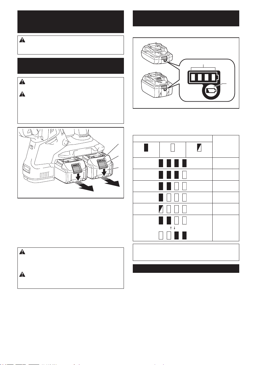
Installing or removing battery
cartridge
CAUTION: Always switch off the tool before
installing or removing of the battery cartridge.
CAUTION: Hold the tool and the battery car-
tridge rmly when installing or removing battery
cartridge. Failure to hold the tool and the battery
cartridgermlymaycausethemtoslipoffyourhands
and result in damage to the tool and battery cartridge
andapersonalinjury.
3
2
1
►1. Red indicator 2. Button 3. Battery cartridge
Toremovethebatterycartridge,slideitfromthetool
while sliding the button on the front of the cartridge.
Toinstallthebatterycartridge,alignthetongueonthe
battery cartridge with the groove in the housing and slip
it into place. Insert it all the way until it locks in place
with a little click. If you can see the red indicator on the
upper side of the button, it is not locked completely.
CAUTION: Always install the battery cartridge
fully until the red indicator cannot be seen. If not,
itmayaccidentallyfalloutofthetool,causinginjuryto
you or someone around you.
CAUTION: Do not install the battery cartridge
forcibly. If the cartridge does not slide in easily, it is
not being inserted correctly.
Indicating the remaining battery
capacity
Only for battery cartridges with the indicator
1
2
►1. Indicator lamps 2. Check button
Press the check button on the battery cartridge to indi-
catetheremainingbatterycapacity.Theindicatorlamps
light up for a few seconds.
Indicator lamps Remaining
capacity
Lighted Off Blinking
75% to 100%
50% to 75%
25% to 50%
0% to 25%
Charge the
battery.
Thebattery
may have
malfunctioned.
NOTE: Depending on the conditions of use and the
ambient temperature, the indication may differ slightly
from the actual capacity.
Tool / battery protection system
Thetoolisequippedwithatool/batteryprotectionsys-
tem.Thissystemautomaticallycutsoffpowertothe
motortoextendtoolandbatterylife.Thetoolwillauto-
matically stop during operation if the tool or battery is
placed under one of the following conditions:
Overload protection
When the battery is operated in a manner that causes
it to draw an abnormally high current, the tool automat-
ically stops without any indication. In this situation, turn
the tool off and stop the application that caused the tool
tobecomeoverloaded.Thenturnthetoolontorestart.
7 ENGLISH
Overheat protection
When the tool or battery is overheated, the tool stops
automatically. In this case, let the tool and battery cool
before turning the tool on again.
NOTE: When the tool is overheated, the lamp blinks.
Overdischarge protection
When the battery capacity is not enough, the tool stops
automatically. In this case, remove the battery from the
tool and charge the battery.
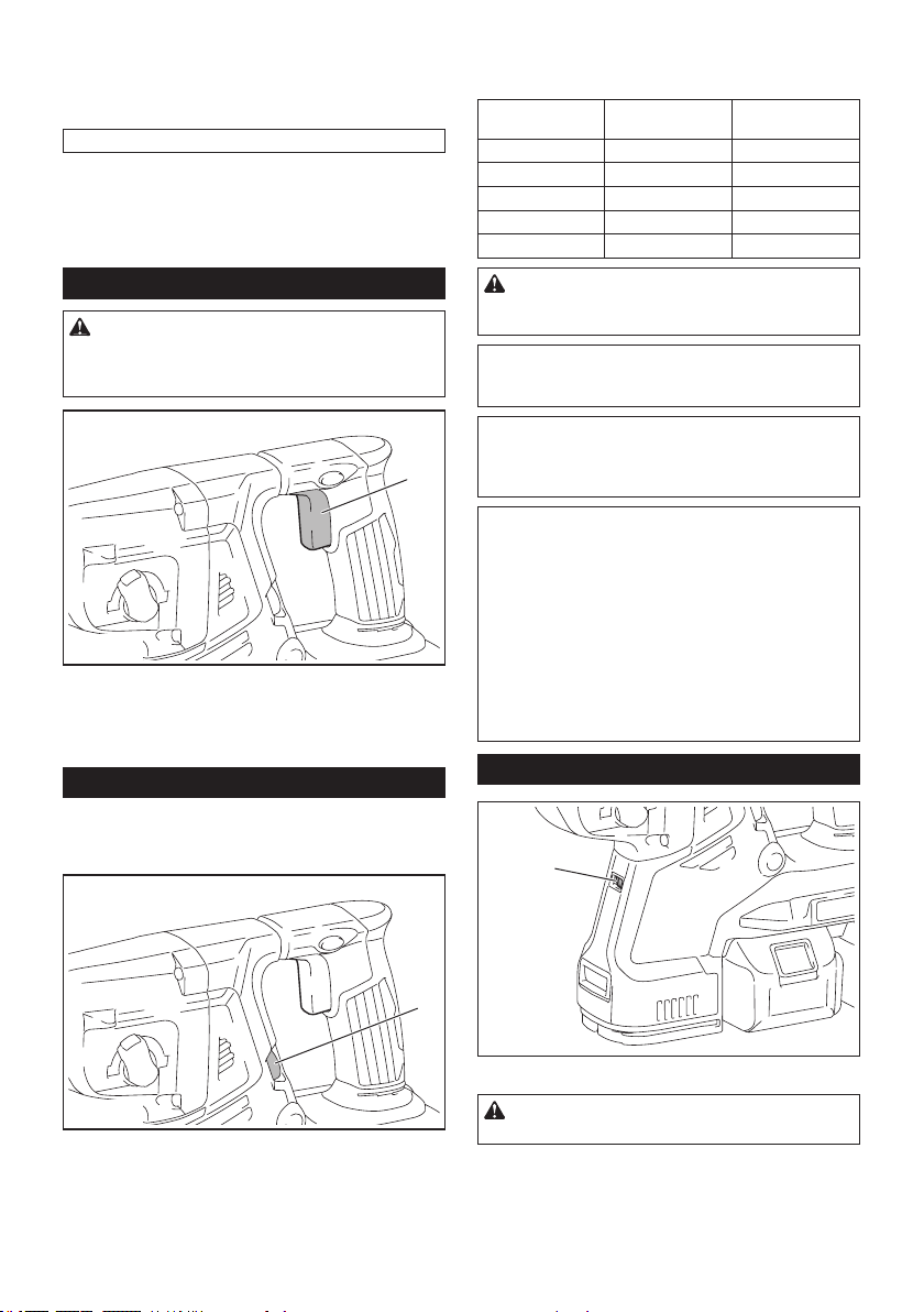
Switch action
WARNING: Before installing the battery car-
tridge into the tool, always check to see that the
switch trigger actuates properly and returns to
the "OFF" position when released.
1
►1. Switch trigger
Tostartthetool,simplypulltheswitchtrigger.Tool
speed is increased by increasing pressure on the switch
trigger. Release the switch trigger to stop.
Speed change
Therevolutionsandblowsperminutecanbeadjusted
byturningtheadjustingdial.Thedialismarked1(low-
est speed) to 5 (full speed).
1
►1.Adjustingdial
Refer to the table below for the relationship between the
numberontheadjustingdialandtherevolutionsand
blows per minute.
Number Revolutions per
minute
Blows per minute
5 980 5,000
4 810 4,130
3 640 3,260
2 470 2,400
1 300 1,550
CAUTION: Do not turn the adjusting dial when
the tool is running. Failure to do so may result in
the loss of control of the tool and cause an injury.
NOTICE: If the tool is operated continuously at
low speed for a long time, the motor will get over-
loaded, resulting in tool malfunction.
NOTICE: The speed adjusting dial can be turned
only as far as 5 and back to 1. Do not force it past
5 or 1, or the speed adjusting function may no
longer work.
NOTE: Soft no-load rotation function (For XRH10/
XRH11)
Whenthespeedadjustingdialissetto"3"orhigher,
the tool automatically reduces the speed at no-load to
reduce the vibration under no-load. Once operation
starts with a bit against concrete, blows per minute
increase and reach the numbers as shown in the
table. When temperature is low and there is less
uidityingrease,thetoolmaynothavethisfunction
even with the motor rotating.
Thisfunctionisnotavailablewhenthedustcollection
system is installed.
Lighting up the front lamp
1
►1. Lamp
CAUTION: Do not look in the light or see the
source of light directly.
Pulltheswitchtriggertolightupthelamp.Thelamp
keeps on lighting while the switch trigger is being pulled.
Thelampgoesoutapproximately10secondsafter
releasing the switch trigger.
8 ENGLISH
CAUTION: For XRH10/XRH11
If the lamp goes off after blinking for a few sec-
onds, the active feedback sensing technology or
the soft no-load rotation function is not working
properly. Ask your local Makita Service Center for
repair.
NOTE: Use a dry cloth to wipe the dirt off the lens of
the lamp. Be careful not to scratch the lens of lamp, or
it may lower the illumination.
NOTE: If the dust collection system is installed on the
tool, the lamp of the dust collection system lights up
instead of the lamp of the tool.
Reversing switch action
1
AB
►1. Reversing switch lever
CAUTION: Always check the direction of
rotation before operation.
CAUTION: Use the reversing switch only after
the tool comes to a complete stop. Changing the
direction of rotation before the tool stops may dam-
age the tool.
CAUTION: When not operating the tool,
always set the reversing switch lever to the neu-
tral position.
Thistoolhasareversingswitchtochangethedirection
of rotation. Depress the reversing switch lever from the
AsideforclockwiserotationorfromtheBsideforcoun-
terclockwise rotation.
When the reversing switch lever is in the neutral posi-
tion, the switch trigger cannot be pulled.
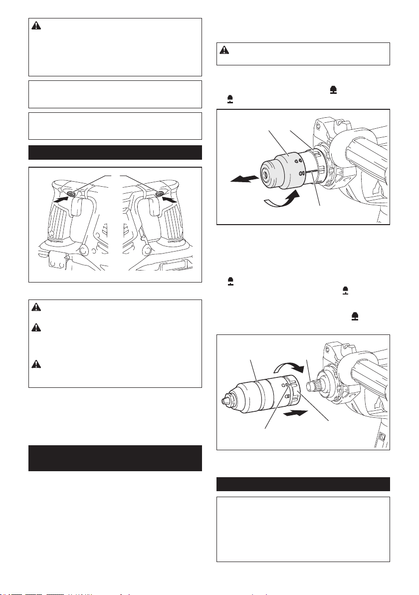
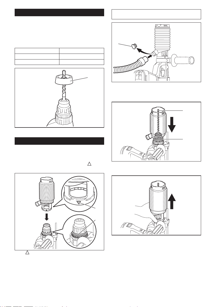
Changing the quick change chuck
for SDS-plus
For XRH11
ThequickchangechuckforSDS-pluscanbeeasily
exchanged for the quick change drill chuck.
Removing the quick change chuck
for SDS-plus
CAUTION: Before removing the quick change
chuck for SDS-plus, be sure to remove the bit.
Grasp the change cover of the quick change chuck for
SDS-plus and turn in the direction of the arrow until
the change cover line moves from the
symbol to
the
symbol. Pull forcefully in the direction of the arrow.
1 2
3
►1. Quick change chuck for SDS-plus 2. Change
cover 3. Change cover line
Installing the quick change drill chuck
Check the line of the quick change drill chuck shows
the
symbol. Grasp the change cover of the quick
change drill chuck and set the line to the
symbol.
Place the quick change drill chuck on the spindle of the
tool. Grasp the change cover of the quick change drill
chuck and turn the change cover line to the
symbol
until a click can clearly be heard.
1 2
3
4
►1. Quick change drill chuck 2. Spindle 3. Change
cover line 4. Change cover
Selecting the action mode
NOTICE: Do not rotate the action mode chang-
ing knob when the tool is running.Thetoolwillbe
damaged.
NOTICE: To avoid rapid wear on the mode
change mechanism, be sure that the action mode
changing knob is always positively located in one
of the three action mode positions.
9 ENGLISH
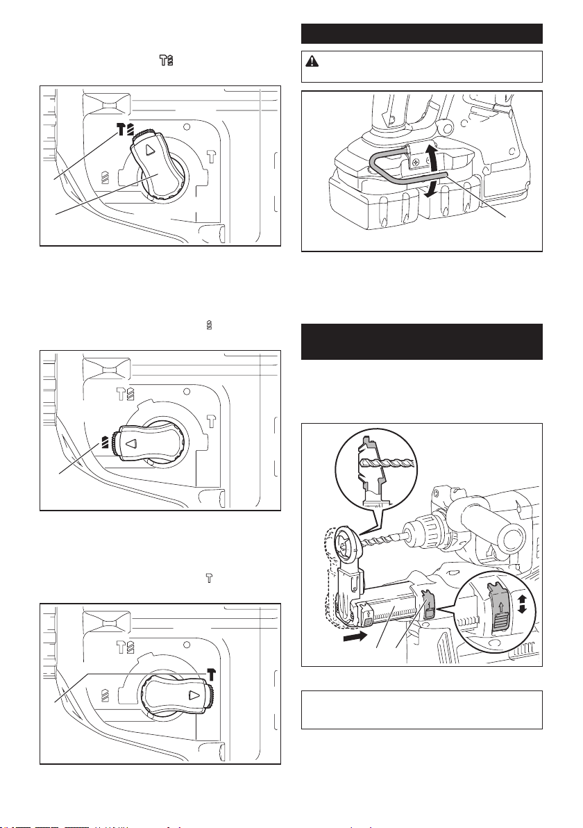
Rotation with hammering
For drilling in concrete, masonry, etc., rotate the action
mode changing knob to the
symbol. Use a tungsten-
carbide tipped bit (optional accessory).
1
2
►1. Rotation with hammering 2.Actionmodechang-
ing knob
Rotation only
For drilling in wood, metal or plastic materials, rotate
the action mode changing knob to the
symbol. Use a
twist drill bit or wood drill bit.
1
►1. Rotation only
Hammering only
For chipping, scaling or demolition operations, rotate
the action mode changing knob to the
symbol. Use a
bull point, cold chisel, scaling chisel, etc.
1
►1. Hammering only
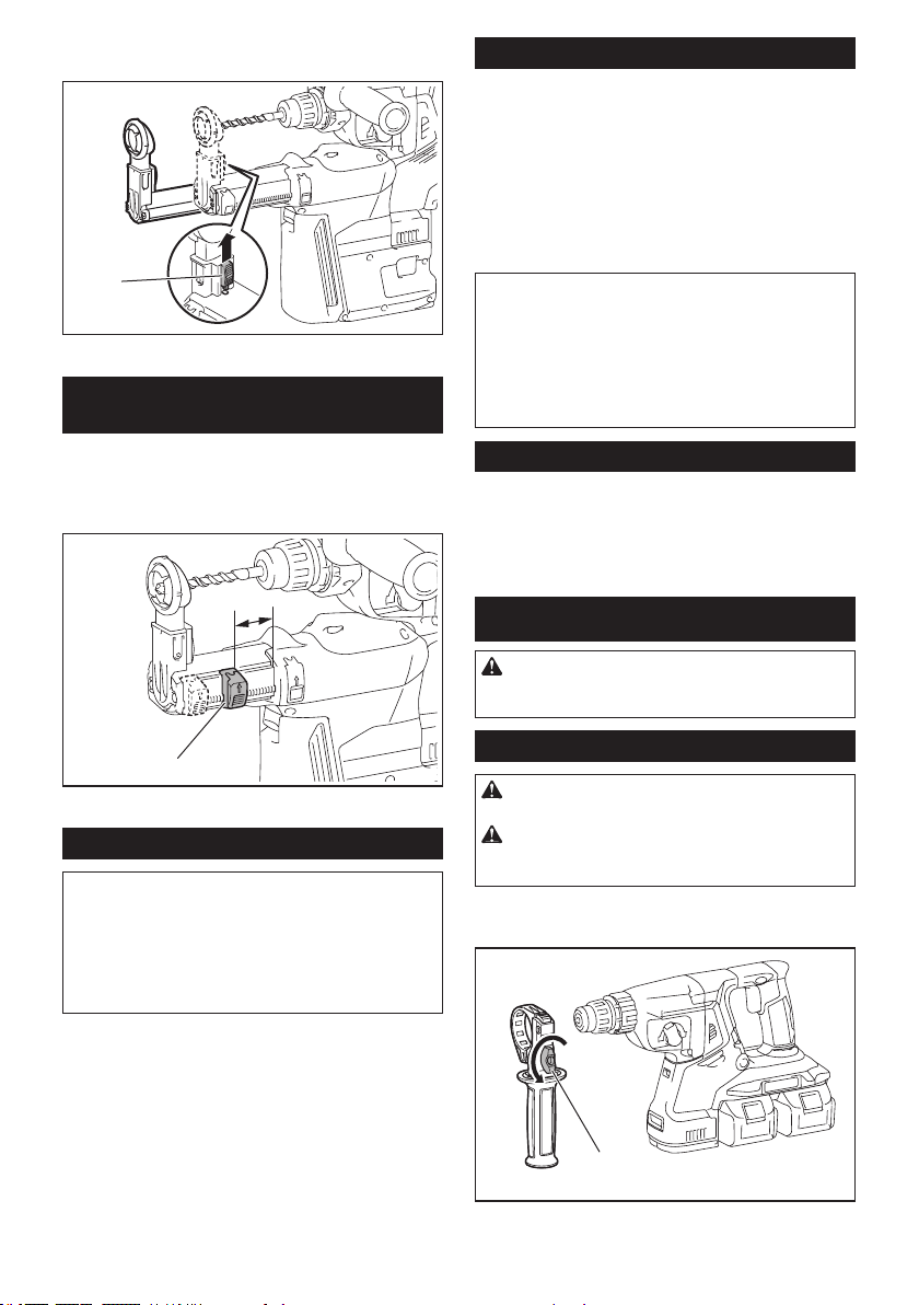
Hook
CAUTION: Never hook the tool at high loca-
tion or on potentially unstable surface.
1
►1. Hook
Thehookisconvenientfortemporarilyhangingthetool.
Tousethehook,simplyliftuphookuntilitsnapsinto
the open position. When not in use, always lower hook
until it snaps into the closed position.
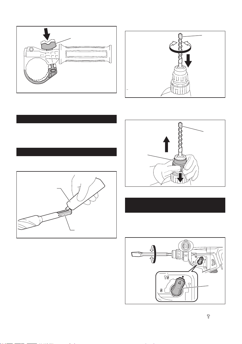
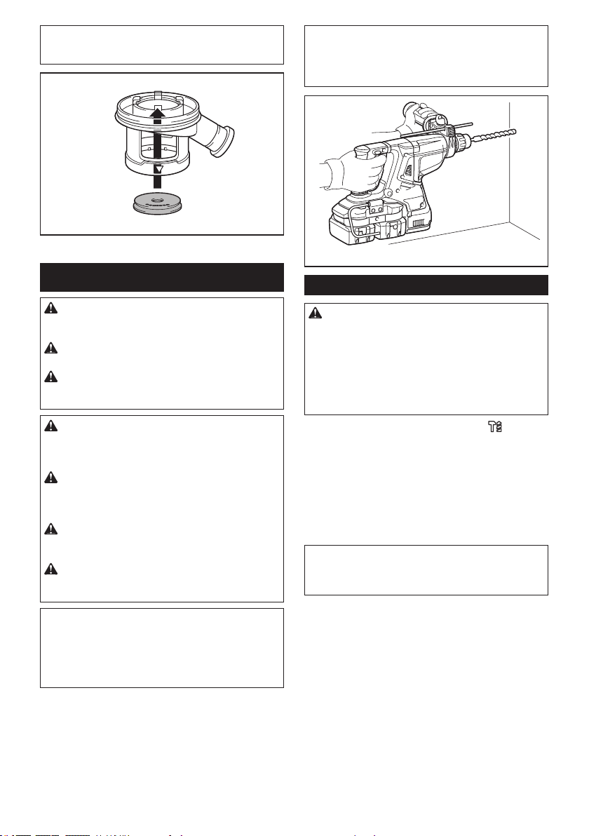
Adjusting the nozzle position of the
dust collection system
Optional accessory
Pushintheguidewhilepushinguptheguideadjust-
ment button, and then release the button at the desired
position.
1 2
►1. Guide 2.Guideadjustmentbutton
NOTE:Beforeadjustingthenozzleposition,release
the nozzle forward completely by pushing up the
guideadjustmentbutton.
10 ENGLISH
If a long drill bit is installed, extend the guide by pushing
up the extension button.
1
►1. Extension button
Adjusting the drilling depth of the
dust collection system
Optional accessory
Slidethedepthadjustmentbuttontothedesiredposi-
tionwhilepushingitup.Thedistance(A)isthedrilling
depth.
A
1
►1.Depthadjustmentbutton
Torque limiter
NOTICE: As soon as the torque limiter actuates,
switch off the tool immediately.Thiswillhelppre-
vent premature wear of the tool.
NOTICE: Drill bits such as hole saw, which tend
to pinch or catch easily in the hole, are not appro-
priate for this tool.Thisisbecausetheywillcause
the torque limiter to actuate too frequently.
Thetorquelimiterwillactuatewhenacertaintorque
levelisreached.Themotorwilldisengagefromthe
output shaft. When this happens, the drill bit will stop
turning.
Electronic function
Thetoolisequippedwiththeelectronicfunctionsfor
easy operation.
• Constantspeedcontrol
Thespeedcontrolfunctionprovidestheconstant
rotation speed regardless of load conditions.
• ActiveFeedbacksensingTechnology(ForXRH10/
XRH11)
If the tool is swung at the predetermined accelera-
tion during operation, the motor is forcibly stopped
to reduce the burden on the wrist.
NOTE:Thisfunctiondoesnotworkiftheacceleration
does not reach the predetermined one when the tool
is swung.
NOTE: If the bit is swung at the predetermined
acceleration during chipping, scaling, or demolishing,
the motor is forcibly stopped. In this case, release
the switch trigger, and then pull the switch trigger to
restart the tool.
Electric brake
Thistoolisequippedwithanelectricbrake.Ifthetool
consistently fails to quickly stop after the switch trigger
is released, have the tool serviced at a Makita service
center.
ASSEMBLY
CAUTION: Always be sure that the tool is
switched off and the battery cartridge is removed
before carrying out any work on the tool.
Side grip (auxiliary handle)
CAUTION: Always use the side grip to ensure
safe operation.
CAUTION: After installing or adjusting the
side grip, make sure that the side grip is rmly
secured.
Toinstallthesidegrip,followthestepsbelow.
1. Loosen the thumb screw on the side grip.
1
►1.Thumbscrew
11 ENGLISH
2. Attachthesidegripwhilepressingthethumb
screwsothatthegroovesonthegriptintheprotru-
sions on the tool barrel.
1
►1.Thumbscrew
3. Tightenthethumbscrewtosecurethegrip.The
gripcanbexedatdesiredangle.
Grease
Coat the shank end of the drill bit beforehand with a
small amount of grease (about 0.5 - 1 g).
Thischucklubricationassuressmoothactionandlon-
ger service life.
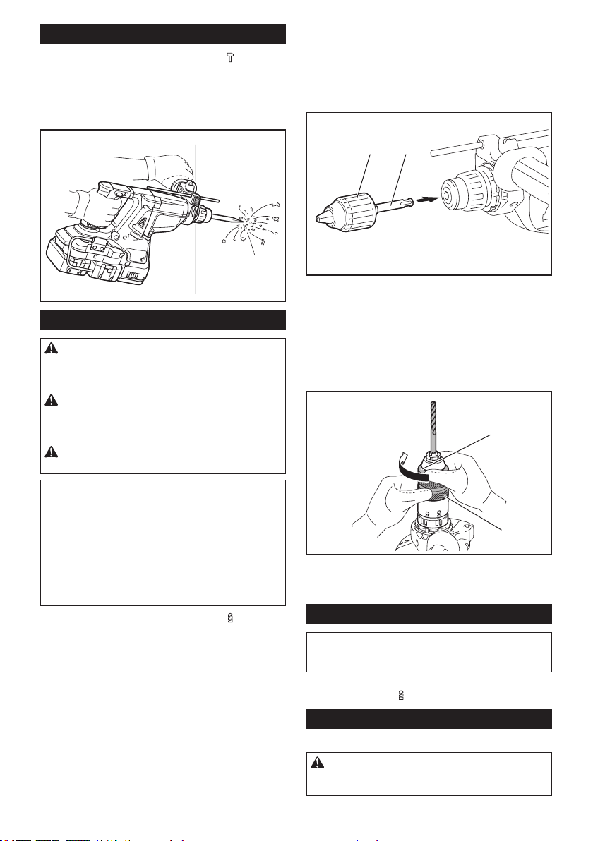
Installing or removing drill bit
Clean the shank end of the drill bit and apply grease
before installing the drill bit.
1
2
►1. Shank end 2. Grease
Insertthedrillbitintothetool.Turnthedrillbitandpush
it in until it engages.
Afterinstallingthedrillbit,alwaysmakesurethatthe
drill bit is securely held in place by trying to pull it out.
1
►1. Drill bit
Toremovethedrillbit,pullthechuckcoverdownallthe
way and pull the drill bit out.
1
2
►1. Drill bit 2. Chuck cover
Chisel angle (when chipping,
scaling or demolishing)
Thechiselcanbesecuredatthedesiredangle.To
change the chisel angle, rotate the action mode chang-
ingknobtotheOsymbol.Turnthechiseltothedesired
angle.
1
►1.Actionmodechangingknob
Rotate the action mode changing knob to the
sym-
bol.Thenmakesurethatthechiselissecurelyheldin
place by turning it slightly.
12 ENGLISH
Depth gauge
Thedepthgaugeisconvenientfordrillingholesof
uniform depth.
Press and hold the lock button, and then insert the
depth gauge into the hex hole. Make sure that the
toothed side of the depth gauge faces the marking.
12
4
3
►1. Depth gauge 2. Lock button 3. Marking
4.Toothedside
Adjustthedepthgaugebymovingitbackandforth
whilepressingthelockbutton.Aftertheadjustment,
release the lock button to lock the depth gauge.
NOTE: Make sure that the depth gauge does not
touch the main body of the tool when attaching it.
Installing or removing the dust
collection system
Optional accessory
Toinstallthedustcollectionsystem,insertthetoolinto
the dust collection system all the way until it locks in
place with a little double click.
Toremovethedustcollectionsystem,pullthetoolwhile
pressing the lock-off button.
1
►1. Lock-off button
13 ENGLISH
Dust cup
Optional accessory
Use the dust cup to prevent dust from falling over the
tool and on yourself when performing overhead drilling
operations.Attachthedustcuptothebitasshownin
thegure.Thesizeofbitswhichthedustcupcanbe
attached to is as follows.
Model Bit diameter
Dust cup 5 6 mm (1/4") - 14.5 mm (9/16")
Dust cup 9 12 mm (15/32") - 16 mm (5/8")
1
►1. Dust cup
Dust cup set
Optional accessory
Before installing the dust cup set, remove the bit from
the tool if installed.
Install the dust cup set on the tool so that the
sym-
bol on the dust cup is aligned with the groove in the tool.
1
2
►1. symbol 2. Groove
NOTE: If you connect a vacuum cleaner to the dust
cup set, remove the dust cap before connecting it.
1
►1. Dust cap
Toremovethedustcupset,removethebitwhilepulling
the chuck cover in the direction of the arrow.
1
2
►1. Bit 2. Chuck cover
Hold the root of dust cup and pull it out.
14 ENGLISH
NOTE: If the cap comes off from the dust cup, attach
it with its printed side facing up so that groove on the
captsintheinsideperipheryoftheattachment.
OPERATION
CAUTION: Always use the side grip (auxiliary
handle) and rmly hold the tool by both side grip
and switch handle during operations.
CAUTION: Always make sure that the work-
piece is secured before operation.
CAUTION: Do not pull the tool out forcibly
even the bit gets stuck. Loss of control may
cause injury.
CAUTION: The dust collection system is
intended for drilling in concrete only. Do not use
the dust collection system for drilling in metal or
wood.
CAUTION: When using the tool with the dust
collection system, be sure to attach the lter
to the dust collection system to prevent dust
inhalation.
CAUTION: Before using the dust collection
system, check that the lter is not damaged.
Failure to do so may cause dust inhalation.
CAUTION: The dust collection system col-
lects the generated dust at a considerable rate,
but not all dust can be collected.
NOTICE: Do not use the dust collection system
for core drilling or chiseling.
NOTICE: Do not use the dust collection system
for drilling in wet concrete or use this system
in wet environment. Failure to do so may cause
malfunction.
NOTE: If the battery cartridge is in low temperature,
the tool’s capability may not be fully obtained. In this
case, warm up the battery cartridge by using the
tool with no load for a while to fully obtain the tool’s
capability.
Hammer drilling operation
CAUTION:Thereistremendousandsudden
twisting force exerted on the tool/drill bit at the time of
hole break-through, when the hole becomes clogged
with chips and particles, or when striking reinforcing
rods embedded in the concrete. Always use the side
grip (auxiliary handle) and rmly hold the tool by
both side grip and switch handle during opera-
tions. Failure to do so may result in the loss of control
ofthetoolandpotentiallysevereinjury.
Set the action mode changing knob to the symbol.
Position the drill bit at the desired location for the hole,
then pull the switch trigger. Do not force the tool. Light
pressure gives best results. Keep the tool in position
and prevent it from slipping away from the hole.
Do not apply more pressure when the hole becomes
clogged with chips or particles. Instead, run the tool at
an idle, then remove the drill bit partially from the hole.
By repeating this several times, the hole will be cleaned
out and normal drilling may be resumed.
NOTE: Eccentricity in the drill bit rotation may occur
whileoperatingthetoolwithnoload.Thetoolauto-
maticallycentersitselfduringoperation.Thisdoesnot
affect the drilling precision.
15 ENGLISH
Chipping/Scaling/Demolition
Set the action mode changing knob to the symbol.
Holdthetoolrmlywithbothhands.Turnthetoolon
and apply slight pressure on the tool so that the tool will
not bounce around, uncontrolled.
Pressing very hard on the tool will not increase the
efciency.
Drilling in wood or metal
CAUTION: Hold the tool rmly and exert care
when the drill bit begins to break through the
workpiece.Thereisatremendousforceexertedon
the tool/drill bit at the time of hole break through.
CAUTION: A stuck drill bit can be removed
simply by setting the reversing switch to reverse
rotation in order to back out. However, the tool
may back out abruptly if you do not hold it rmly.
CAUTION: Always secure workpieces in a
vise or similar hold-down device.
NOTICE: Never use “rotation with hammering”
when the drill chuck is installed on the tool.The
drill chuck may be damaged.
Also,thedrillchuckwillcomeoffwhenreversingthe
tool.
NOTICE: Pressing excessively on the tool will
not speed up the drilling. In fact, this excessive
pressure will only serve to damage the tip of your drill
bit, decrease the tool performance and shorten the
service life of the tool.
Set the action mode changing knob to the symbol.
For XRH08/XRH10
Optional accessory
Attachthechuckadaptertoakeylessdrillchuckto
which 1/2"-20 size screw can be installed, and then
install them to the tool. When installing it, refer to the
section “Installing or removing drill bit”.
1
2
►1. Keyless drill chuck 2. Chuck adapter
For XRH11
Use the quick change drill chuck as standard equipment. When
installing it, refer to "changing the quick change chuck for SDS-plus".
Hold the ring and turn the sleeve counterclockwise to open the
chuckjaws.Placethebitinthechuckasfarasitwillgo.Holdthe
ringrmlyandturnthesleeveclockwisetotightenthechuck.
1
2
►1. Sleeve 2. Ring
Toremovethebit,holdtheringandturnthesleeve
counterclockwise.
Diamond core drilling
NOTICE: If performing diamond core drilling
operations using “rotation with hammering”
action, the diamond core bit may be damaged.
When performing diamond core drilling operations, always set
the change lever to the
position to use "rotation only" action.
Disposing of dust
Optional accessory
CAUTION: Always be sure that the tool is
switched off and the battery cartridge is removed
before carrying out any work on the tool.
16 ENGLISH
CAUTION: Be sure to wear dust mask when
disposing of dust.
CAUTION: Empty the dust case regularly
before the dust case becomes full. Failure to do so
may decrease the dust collection performance and
cause dust inhalation.
CAUTION: The performance of dust collection
decreases if the lter in the dust case become
clogged. Replace the lter with new one after
approximately 200 times of dust fulllment as a
guide. Failure to do so may cause dust inhalation.
1. Remove the dust case while pressing down the
lever of the dust case.
1
►1. Lever
2. Open the cover of the dust case.
1
►1. Cover
3. Disposeofthedust,andthencleanthelter.
NOTICE: When cleaning the lter, do not touch
the lter with brush or similar, or blow com-
pressed air on the lter. It may damage the lter.
Blow-out bulb
Optional accessory
Afterdrillingthehole,usetheblow-outbulbtocleanthe
dust out of the hole.
Using dust cup set
Optional accessory
Fit the dust cup set against the ceiling when operating
the tool.
NOTICE: Do not use the dust cup set when drill-
ing in metal or similar. It may damage the dust
cup set due to the heat produced by small metal
dust or similar.
NOTICE: Do not install or remove the dust cup
set with the drill bit installed in the tool. It may
damage the dust cup set and cause dust leak.
17 ENGLISH
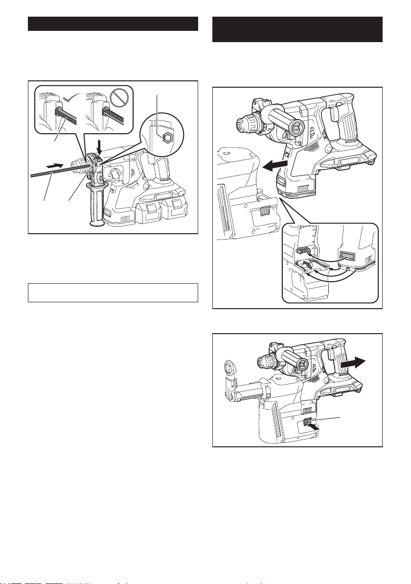
WIRELESS ACTIVATION
FUNCTION
Optional accessory for XRH10/XRH11
What you can do with the wireless
activation function
Thewirelessactivationfunctionenablescleanandcom-
fortable operation. By connecting a supported vacuum
cleaner to the tool, you can run the vacuum cleaner
automatically along with the switch operation of the tool.
Tousethewirelessactivationfunction,preparefollow-
ing items:
• Awirelessunit(optionalaccessory)
• Avacuumcleanerwhichsupportsthewireless
activation function
Theoverviewofthewirelessactivationfunction
setting is as follows. Refer to each section for detail
procedures.
1. Installing the wireless unit
2. Toolregistrationforthevacuumcleaner
3. Starting the wireless activation function
Installing the wireless unit
Optional accessory
CAUTION: Place the tool on a at and stable
surface when installing the wireless unit.
NOTICE: Clean the dust and dirt on the tool
before installing the wireless unit. Dust or dirt
may cause malfunction if it comes into the slot of the
wireless unit.
NOTICE: To prevent the malfunction caused by
static, touch a static discharging material, such
as a metal part of the tool, before picking up the
wireless unit.
NOTICE: When installing the wireless unit,
always be sure that the wireless unit is inserted
in the correct direction and the lid is completely
closed.
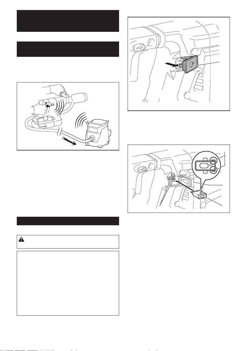
1. Openthelidonthetoolasshowninthegure.
1
►1. Lid
2. Insert the wireless unit to the slot and then close
the lid.
Wheninsertingthewirelessunit,aligntheprojections
with the recessed portions on the slot.
3
2
1
4
►1. Wireless unit 2.Projection3. Lid 4. Recessed
portion
18 ENGLISH
When removing the wireless unit, open the lid slowly.
Thehooksonthebackofthelidwillliftthewirelessunit
as you pull up the lid.
1
2
3
►1. Wireless unit 2. Hook 3. Lid
Afterremovingthewirelessunit,keepitinthesupplied
case or a static-free container.
NOTICE: Always use the hooks on the back of
the lid when removing the wireless unit. If the
hooks do not catch the wireless unit, close the lid
completely and open it slowly again.
Tool registration for the vacuum
cleaner
NOTE:AMakitavacuumcleanersupportingthe
wireless activation function is required for the tool
registration.
NOTE: Finish installing the wireless unit to the tool
before starting the tool registration.
NOTE: During the tool registration, do not pull the
switch trigger or turn on the power switch on the
vacuum cleaner.
NOTE: Refer to the instruction manual of the vacuum
cleaner, too.
If you wish to activate the vacuum cleaner along with
theswitchoperationofthetool,nishthetoolregistra-
tion beforehand.
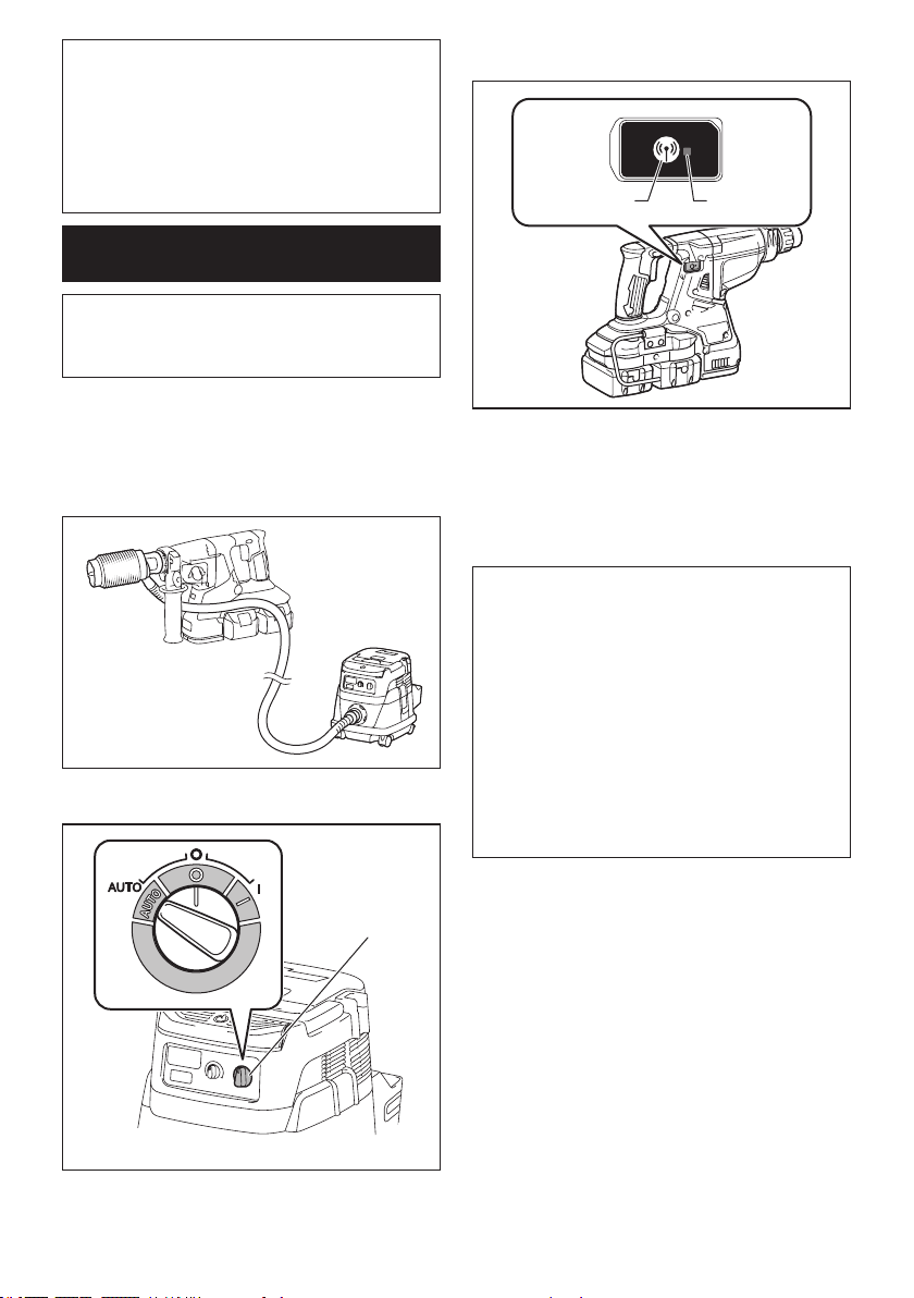
1. Install the batteries to the vacuum cleaner and the
tool.
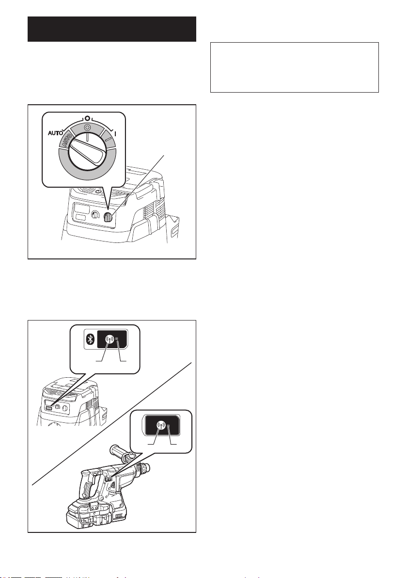
2. Set the stand-by switch on the vacuum cleaner to
"AUTO".
1
►1. Stand-by switch
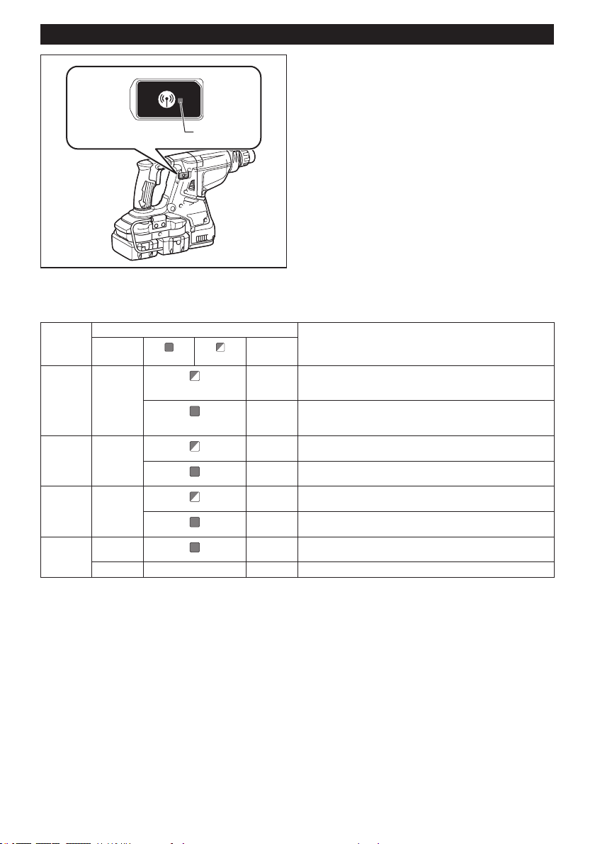
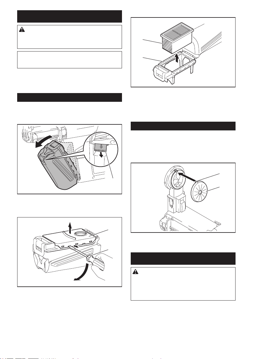
3. Press the wireless activation button on the vac-
uum cleaner for 3 seconds until the wireless activation
lampblinksingreen.Andthenpressthewirelessacti-
vation button on the tool in the same way.
1 2
1 2
►1. Wireless activation button 2. Wireless activation
lamp
If the vacuum cleaner and the tool are linked success-
fully, the wireless activation lamps will light up in green
for 2 seconds and start blinking in blue.
19 ENGLISH
NOTE:Thewirelessactivationlampsnishblinking
in green after 20 seconds elapsed. Press the wireless
activation button on the tool while the wireless acti-
vation lamp on the cleaner is blinking. If the wireless
activation lamp does not blink in green, push the wire-
lessactivationbuttonbrieyandholditdownagain.
NOTE: When performing two or more tool registra-
tionsforonevacuumcleaner,nishthetoolregistra-
tion one by one.
Starting the wireless activation
function
NOTE: Finish the tool registration for the vacuum
cleaner prior to the wireless activation.
NOTE: Refer to the instruction manual of the vacuum
cleaner, too.
Afterregisteringatooltothevacuumcleaner,the
vacuum cleaner will automatically runs along with the
switch operation of the tool.
1. Install the wireless unit to the tool.
2. Connect the hose of the vacuum cleaner with the
tool.
3. Set the stand-by switch on the vacuum cleaner to
"AUTO".
1
►1. Stand-by switch
4. Push the wireless activation button on the tool
briey.Thewirelessactivationlampwillblinkinblue.
1 2
►1. Wireless activation button 2. Wireless activation
lamp
5. Pull the switch trigger of the tool. Check if the
vacuum cleaner runs while the switch trigger is being
pulled.
Tostopthewirelessactivationofthevacuumcleaner,
push the wireless activation button on the tool.
NOTE:Thewirelessactivationlamponthetoolwill
stop blinking in blue when there is no operation for
2 hours. In this case, set the stand-by switch on the
vacuumcleanerto"AUTO"andpushthewireless
activation button on the tool again.
NOTE:Thevacuumcleanerstarts/stopswithadelay.
Thereisatimelagwhenthevacuumcleanerdetects
a switch operation of the tool.
NOTE:Thetransmissiondistanceofthewirelessunit
may vary depending on the location and surrounding
circumstances.
NOTE: When two or more tools are registered to one
vacuum cleaner, the vacuum cleaner may start run-
ning even if you don't pull the switch trigger because
an other user is using the wireless activation function.
20 ENGLISH
Description of the wireless activation lamp status
1
►1. Wireless activation lamp
Thewirelessactivationlampshowsthestatusofthewirelessactivationfunction.Refertothetablebelowforthe
meaning of the lamp status.
Status Wireless activation lamp Description
Color
On
Blinking
Duration
Standby Blue
2 hours Thewirelessactivationofthevacuumcleanerisavailable.The
lamp will automatically turn off when no operation is performed
for 2 hours.
When
the tool is
running.
Thewirelessactivationofthevacuumcleanerisavailableandthe
tool is running.
Tool
registration
Green
20 seconds Ready for the tool registration. Waiting for the registration by the
vacuum cleaner.
2 seconds Thetoolregistrationhasbeennished.Thewirelessactivation
lamp will start blinking in blue.
Cancelling
tool
registration
Red
20 seconds Ready for the cancellation of the tool registration. Waiting for the
cancellation by the vacuum cleaner.
2 seconds Thecancellationofthetoolregistrationhasbeennished.The
wireless activation lamp will start blinking in blue.
Others Red
3 seconds Thepowerissuppliedtothewirelessunitandthewirelessactiva-
tion function is starting up.
Off - - Thewirelessactivationofthevacuumcleanerisstopped.
21 ENGLISH
Cancelling tool registration for the
vacuum cleaner
Perform the following procedure when cancelling the
tool registration for the vacuum cleaner.
1. Install the batteries to the vacuum cleaner and the
tool.
2. Set the stand-by switch on the vacuum cleaner to
"AUTO".
1
►1. Stand-by switch
3. Press the wireless activation button on the vac-
uumcleanerfor6seconds.Thewirelessactivation
lampblinksingreenandthenbecomered.Afterthat,
press the wireless activation button on the tool in the
same way.
1 2
1 2
►1. Wireless activation button 2. Wireless activation
lamp
If the cancellation is performed successfully, the wire-
less activation lamps will light up in red for 2 seconds
and start blinking in blue.
NOTE:Thewirelessactivationlampsnishblinkingin
red after 20 seconds elapsed. Press the wireless acti-
vation button on the tool while the wireless activation
lamp on the cleaner is blinking. If the wireless acti-
vation lamp does not blink in red, push the wireless
activationbuttonbrieyandholditdownagain.

22 ENGLISH
Troubleshooting for wireless activation function
Beforeaskingforrepairs,conductyourowninspectionrst.Ifyoundaproblemthatisnotexplainedinthemanual,
donotattempttodismantlethetool.Instead,askMakitaAuthorizedServiceCenters,alwaysusingMakitareplace-
ment parts for repairs.
State of abnormality Probable cause (malfunction) Remedy
Thewirelessactivationlampdoes
not light/blink.
Thewirelessunitisnotinstalledintothetool.
Thewirelessunitisimproperlyinstalled
into the tool.
Install the wireless unit correctly.
Theterminalofthewirelessunitand/or
the slot is dirty.
Gently wipe off dust and dirt on the terminal of the
wireless unit and clean the slot.
Thewirelessactivationbuttononthe
tool has not been pushed.
Push the wireless activation button on the tool
briey.
Thestand-byswitchonthevacuum
cleanerisnotsetto"AUTO".
Set the stand-by switch on the vacuum cleaner to
"AUTO".
No power supply
Supply the power to the tool and the vacuum cleaner.
Cannotnishtoolregistration/can-
celling tool registration successfully.
Thewirelessunitisnotinstalledintothetool.
Thewirelessunitisimproperlyinstalled
into the tool.
Install the wireless unit correctly.
Theterminalofthewirelessunitand/or
the slot is dirty.
Gently wipe off dust and dirt on the terminal of the
wireless unit and clean the slot.
Thestand-byswitchonthevacuum
cleanerisnotsetto"AUTO".
Set the stand-by switch on the vacuum cleaner to
"AUTO".
No power supply
Supply the power to the tool and the vacuum cleaner.
Incorrect operation
Pushthewirelessactivationbuttonbrieyandperform
the tool registration/cancellation procedures again.
Thetoolandvacuumcleanerisaway
from each other (out of the transmission
range).
Get the tool and vacuum cleaner closer to each other.
Themaximumtransmissiondistanceisapproximately10
m however it may vary according to the circumstances.
Beforenishingthetoolregistration/
cancellation;
- the switch trigger on the tool is pulled or;
- the power button on the vacuum
cleaner is turned on.
Pushthewirelessactivationbuttonbrieyand
perform the tool registration/cancellation procedures
again.
Thetoolregistrationproceduresforthe
toolorvacuumcleanerhasnotnished.
Perform the tool registration procedures for both the
tool and the vacuum cleaner at the same timing.
Radio disturbance by other appliances
which generate high-intensity radio waves.
Keep the tool and vacuum cleaner away from the appli-
ances such as Wi-Fi devices and microwave ovens.
Thevacuumcleanerdoesnotrun
along with the switch operation of
the tool.
Thewirelessunitisnotinstalledintothetool.
Thewirelessunitisimproperlyinstalled
into the tool.
Install the wireless unit correctly.
Theterminalofthewirelessunitand/or
the slot is dirty.
Gently wipe off dust and dirt on the terminal of the
wireless unit and clean the slot.
Thewirelessactivationbuttononthe
tool has not been pushed.
Pushthewirelessactivationbuttonbrieyandmake
sure that the wireless activation lamp is blinking in blue.
Thestand-byswitchonthevacuum
cleanerisnotsetto"AUTO".
Set the stand-by switch on the vacuum cleaner to
"AUTO".
More than 10 tools are registered to the
vacuum cleaner.
Perform the tool registration again.
If more than 10 tools are registered to the vacuum
cleaner, the tool registered earliest will be cancelled
automatically.
Thevacuumcleanererasedalltool
registrations.
Perform the tool registration again.
No power supply
Supply the power to the tool and the vacuum cleaner.
Thetoolandvacuumcleanerisaway
from each other (out of the transmission
range).
Get the tool and vacuum cleaner closer each other.
Themaximumtransmissiondistanceisapproxi-
mately 10 m however it may vary according to the
circumstances.
Radio disturbance by other appliances
which generate high-intensity radio waves.
Keep the tool and vacuum cleaner away from the appli-
ances such as Wi-Fi devices and microwave ovens.
Thevacuumcleanerrunswhilethe
tool's switch trigger is not pulled.
Other users are using the wireless
activation of the vacuum cleaner with
their tools.
Turnoffthewirelessactivationbuttonoftheother
tools or cancel the tool registration of the other
tools.
23 ENGLISH
MAINTENANCE
CAUTION: Always be sure that the tool is
switched off and the battery cartridge is removed
before attempting to perform inspection or
maintenance.
NOTICE: Never use gasoline, benzine, thinner,
alcohol or the like. Discoloration, deformation or
cracks may result.
TomaintainproductSAFETYandRELIABILITY,
repairs,anyothermaintenanceoradjustmentshould
beperformedbyMakitaAuthorizedorFactoryService
Centers, always using Makita replacement parts.
Replacing lter of dust case
Optional accessory
1. Remove the dust case while pressing down the
lever of the dust case.
1
►1. Lever
2. Inserttheat-bladescrewdriverintotheslotsof
theltercovertoremovetheltercover.
2
1
►1. Flat-blade screwdriver 2. Filter cover
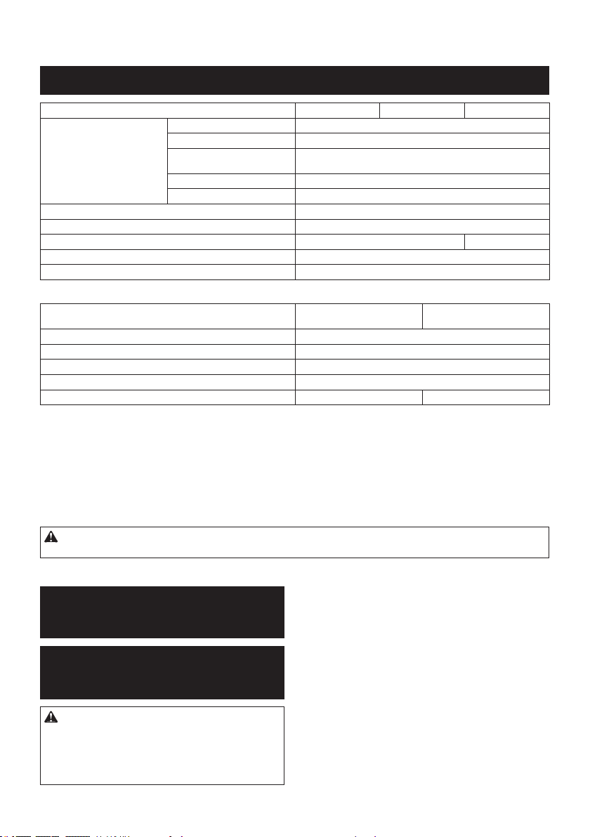
3. Removethelterfromtheltercase.
1
2
►1. Filter 2. Filter case
4. Attachanewltertotheltercase,andthen
attachtheltercover.
5. Close the cover of the dust case, and then attach
the dust case to the dust collection system.
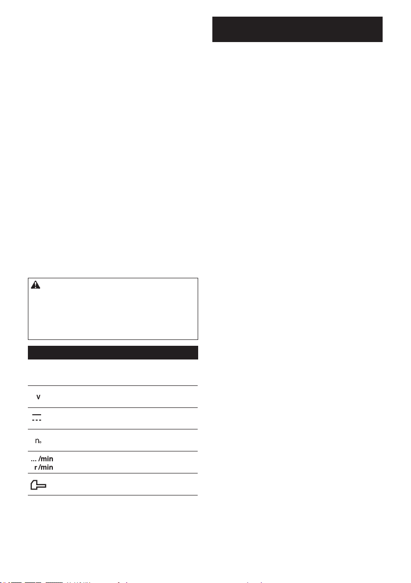
Replacing sealing cap
Optional accessory
If the sealing cap is worn out, the performance of the
dust collection decreases. Replace it if it's worn out.
Remove the sealing cap, and then attach a new one
with its protrusion facing upward.
1
2
►1. Protrusion 2. Sealing cap
OPTIONAL ACCESSORIES
CAUTION: These accessories or attachments
are recommended for use with your Makita tool
specied in this manual.Theuseofanyother
accessories or attachments might present a risk of
injurytopersons.Onlyuseaccessoryorattachment
for its stated purpose.
If you need any assistance for more details regard-
ing these accessories, ask your local Makita Service
Center.
• Carbide-tippeddrillbits(SDS-Pluscarbide-tipped
bits)
• Corebit
• Bullpoint

24
• Diamondcorebit
• Coldchisel
• Scalingchisel
• Groovingchisel
• Chuckadapter
• Keylessdrillchuck
• Bitgrease
• Depthgauge
• Blow-outbulb
• Dustcup
• Dustcupset
• Dustcollectionsystem
• Wirelessunit
• Makitagenuinebatteryandcharger
• Safetygoggles
• Plasticcarryingcase
NOTE: Some items in the list may be included in the
toolpackageasstandardaccessories.Theymay
differ from country to country.
MAKITA LIMITED WARRANTY
Please refer to the annexed warranty sheet for the
most current warranty terms applicable to this product.
If annexed warranty sheet is not available, refer to the
warranty details set forth at below website for your
respective country.
UnitedStatesofAmerica:www.makitatools.com
Canada: www.makita.ca
Other countries: www.makita.com
ENGLISH
25 ESPAÑOL
ESPAÑOL (Instrucciones originales)
ESPECIFICACIONES
Modelo: XRH08 XRH10 XRH11
Capacidades Concreto 28mm(1-1/8″)
Punta de corona 54mm(2-1/8″)
Punta de corona de diamante
(tipo seco)
65mm(2-9/16″)
Acero 13mm(1/2″)
Madera 32mm(1-1/4″)
Velocidad sin carga 0 r/min - 980 r/min
Golpes por minuto 0 gpm - 5 000 gpm
Longitud total 373mm(14-3/4″) 404mm(15-7/8″)
Tensiónnominal 36 V c.c.
Peso neto 3,9 kg - 5,1 kg (8,6 lbs - 11,2 lbs)
Accesorio opcional
Modelo: DX03
(Para los modelos XRH08/XRH10)
DX04
(Para el modelo XRH11)
Desempeñodesucción 350 l/min
Carreradeoperación Hasta190mm(7-1/2″)
Broca apropiada Hasta260mm(10-1/4″)
Tensiónnominal 18 V c.c.
Peso neto 1,4 kg (3,2 lbs) 1,5 kg (3,2 lbs)
• Debidoanuestrocontinuoprogramadeinvestigaciónydesarrollo,lasespecicacionesaquíincluidasestán
sujetasacambiosinprevioaviso.
• Lasespecicacionesyelcartuchodebateríapuedenvariardepaísapaís.
• Elpesopuedevariarenfuncióndelosaccesorios,incluidoelcartuchodebatería.Enlatablasemuestrala
combinacióndepesomásligeroymáspesadoconformealprocedimiento01/2014deEPTA.
Cartucho de batería aplicable
BL1815N / BL1820B / BL1830 / BL1830B / BL1840B / BL1850B / BL1860B
• Algunosdeloscartuchosdebateríaenumeradosarribapodríannoestardisponiblesdependiendodesuárea
de residencia.
ADVERTENCIA: Use únicamente los cartuchos de batería indicados arriba. El uso de cualquier otro
cartuchodebateríapodríaocasionarunalesióny/ounincendio.
ADVERTENCIAS DE
SEGURIDAD
Advertencias generales de
seguridad para herramientas
eléctricas
ADVERTENCIA: Lea todas las advertencias
de seguridad, instrucciones, ilustraciones y espe-
cicaciones suministradas con esta herramienta
eléctrica. El no seguir todas las instrucciones indi-
cadasacontinuaciónpodríaocasionarunadescarga
eléctrica, incendio y/o lesiones graves.
Conserve todas las advertencias
e instrucciones como referencia
en el futuro.
En las advertencias, el término “herramienta eléctrica” se
reereasuherramientaeléctricadefuncionamientocon
conexiónalaredeléctrica(concableadoeléctrico)oherra-
mientaeléctricadefuncionamientoabatería(inalámbrica).
Seguridad en el área de trabajo
1. Mantenga el área de trabajo limpia y bien ilu-
minada.Lasáreasoscurasodesordenadasson
propensas a accidentes.
2. No utilice las herramientas eléctricas en
atmósferas explosivas, tal como en la presen-
cia de líquidos, gases o polvo inamables. Las
herramientas eléctricas crean chispas que pueden
prender fuego al polvo o los humos.

26 ESPAÑOL
3. Mantenga a los niños y curiosos alejados
mientras utiliza una herramienta eléctrica. Las
distracciones le pueden hacer perder el control.
Seguridad eléctrica
1. Las clavijas de conexión de las herramientas
eléctricas deberán encajar perfectamente en la
toma de corriente. No modique nunca la cla-
vija de conexión de ninguna forma. No utilice
ninguna clavija adaptadora con herramientas
eléctricas que tengan conexión a tierra (puesta
a tierra). Lautilizacióndeclavijasnomodica-
dasyqueencajenperfectamenteenlatomade
corrientereduciráelriesgodequeseproduzca
una descarga eléctrica.
2. Evite tocar con el cuerpo supercies conec-
tadas a tierra o puestas a tierra tales como
tubos, radiadores, cocinas y refrigeradores. Si
su cuerpo es puesto a tierra o conectado a tierra
existiráunmayorriesgodequesufraunades-
carga eléctrica.
3. No exponga las herramientas eléctricas a la
lluvia ni a condiciones húmedas. La entrada de
aguaenunaherramientaeléctricaaumentaráel
riesgo de que se produzca una descarga eléctrica.
4. No maltrate el cable. Nunca utilice el cable
para transportar, jalar o desconectar la herra-
mienta eléctrica. Mantenga el cable alejado del
calor, aceite, objetos cortantes o piezas móvi-
les. Los cables dañados o enredados aumentan
el riesgo de sufrir una descarga eléctrica.
5. Cuando utilice una herramienta eléctrica en
exteriores, utilice un cable de extensión apro-
piado para uso en exteriores.Lautilizaciónde
un cable apropiado para uso en exteriores redu-
ciráelriesgodequeseproduzcaunadescarga
eléctrica.
6. Si no es posible evitar usar una herramienta
eléctrica en condiciones húmedas, utilice un
alimentador protegido con interruptor de cir-
cuito de falla a tierra (ICFT).ElusodeunICFT
reduce el riesgo de descarga eléctrica.
7. Las herramientas eléctricas pueden producir
campos electromagnéticos (CEM) que no son
dañinos para el usuario. Sin embargo, si los
usuarios tienen marcapasos y otros dispositivos
médicossimilares,deberánconsultaralfabricante
de su dispositivo y/o a su médico antes de operar
esta herramienta eléctrica.
Seguridad personal
1. Manténgase alerta, preste atención a lo que
está haciendo y utilice su sentido común
cuando opere una herramienta eléctrica. No
utilice una herramienta eléctrica cuando esté
cansado o bajo la inuencia de drogas, alco-
hol o medicamentos.Unmomentodedistracción
mientras opera las herramientas eléctricas puede
terminarenunalesióngrave.
2. Use equipo de protección personal. Póngase
siempre protección para los ojos. El equipo
protectortalcomomáscaracontraelpolvo,zapa-
tosdeseguridadantiderrapantes,cascorígidoy
protecciónparaoídosutilizadoenlascondiciones
apropiadasreduciráelriesgodelesiones.
3. Impida el encendido accidental. Asegúrese
de que el interruptor esté en la posición de
apagado antes de conectar a la alimentación
eléctrica y/o de colocar el cartucho de batería,
así como al levantar o cargar la herramienta.
Cargar las herramientas eléctricas con su dedo
en el interruptor o enchufarlas con el interrup-
tor encendido hace que los accidentes sean
comunes.
4. Retire cualquier llave de ajuste o llave de
apriete antes de encender la herramienta. Una
llavedeajusteollavedeaprietequehayasido
dejadapuestaenunapartegiratoriadelaherra-
mientaeléctricapuedeocasionaralgunalesión.
5. No utilice la herramienta donde no alcance.
Mantenga los pies sobre suelo rme y el equi-
librio en todo momento.Estopermiteunmejor
control de la herramienta eléctrica en situaciones
inesperadas.
6. Use una vestimenta apropiada. No use ropa
suelta ni alhajas. Mantenga el cabello, la ropa
y los guantes alejados de las piezas móviles.
Lasprendasdevestirholgadas,lasalhajasy
elcabellolargosueltopodríanengancharseen
estaspiezasmóviles.
7. Si dispone de dispositivos para la conexión
de equipos de extracción y recolección de
polvo, asegúrese de conectarlos y utilizarlos
debidamente.Hacerusodelarecolecciónde
polvo puede reducir los riesgos relacionados con
el polvo.
8. No permita que la familiaridad adquirida
debido al uso frecuente de las herramientas
haga que se sienta conado e ignore los prin-
cipios de seguridad de las herramientas. Un
descuidopodríaocasionarunalesióngraveen
unafraccióndesegundo.
9. Utilice siempre gafas protectoras para prote-
ger sus ojos de lesiones al usar herramientas
eléctricas. Las gafas deben cumplir con la
Norma ANSI Z87.1 en EUA.
Es responsabilidad del empleador imponer
el uso de equipos protectores de seguridad
apropiados a los operadores de la herramienta
y demás personas cerca del área de trabajo.
Mantenimiento y uso de la herramienta eléctrica
1. No fuerce la herramienta eléctrica. Utilice la
herramienta eléctrica correcta para su aplica-
ción.Laherramientaeléctricaadecuadaharáun
mejortrabajoydeformamásseguraalaveloci-
dad para la que ha sido fabricada.
2. No utilice la herramienta eléctrica si el inte-
rruptor no la enciende y apaga. Cualquier
herramienta eléctrica que no pueda ser contro-
lada con el interruptor es peligrosa y debe ser
reemplazada.
3. Desconecte la clavija de la fuente de alimen-
tación y/o retire la batería de la herramienta
eléctrica, en caso de ser removible, antes de
realizar ajustes, cambiar accesorios o almace-
nar las herramientas eléctricas.Talesmedidas
deseguridadpreventivasreduciránelriesgo
de poner en marcha la herramienta eléctrica de
forma accidental.

27 ESPAÑOL
4. Guarde la herramienta eléctrica que no use
fuera del alcance de los niños y no permita
que las personas que no están familiarizadas
con ella o con las instrucciones la operen. Las
herramientas eléctricas son peligrosas en manos
de personas que no saben operarlas.
5. Dé mantenimiento a las herramientas eléctri-
cas y los accesorios. Compruebe que no haya
piezas móviles desalineadas o estancadas,
piezas rotas y cualquier otra condición que
pueda afectar al funcionamiento de la herra-
mienta eléctrica. Si la herramienta eléctrica
está dañada, haga que la reparen antes de
utilizarla. Muchos de los accidentes son ocasio-
nados por no dar un mantenimiento adecuado a
las herramientas eléctricas.
6.
Mantenga las herramientas de corte limpias y
losas. Si recibe un mantenimiento adecuado y
tienelosbordesalados,esprobablequelaherra-
mientaseatasquemenosyseamásfácilcontrolarla.
7.
Utilice la herramienta eléctrica, los accesorios y
las brocas de acuerdo con estas instrucciones,
considerando las condiciones laborales y el
trabajo a realizar. Si utiliza la herramienta eléctrica
para realizar operaciones distintas de las indicadas,
podrápresentarseunasituaciónpeligrosa.
8. Mantenga los mangos y supercies de asi-
miento secos, limpios y libres de aceite o
grasa.Losmangosysuperciesdeasimiento
resbalososnopermitenunamanipulaciónsegura
ni el control de la herramienta en situaciones
inesperadas.
9. Cuando vaya a utilizar esta herramienta, evite
usar guantes de trabajo de tela ya que éstos
podrían atorarse.Silosguantesdetrabajode
telallegaranaatorarseenlaspiezasmóviles,
estopodríaocasionarlesionespersonales.
Uso y cuidado de la herramienta a batería
1. Recargue sólo con el cargador especicado
por el fabricante. Un cargador que es adecuado
paraunsolotipodebateríapuedegenerarriesgo
deincendioalserutilizadoconotrabatería.
2. Utilice las herramientas eléctricas solamente
con las baterías designadas especícamente
para ellas.Lautilizacióndecualquierotrabatería
puede crear un riesgo de lesiones o incendio.
3. Cuando no se esté usando la batería, mantén-
gala alejada de otros objetos metálicos, como
sujetapapeles (clips), monedas, llaves, clavos,
tornillos u otros objetos pequeños de metal
los cuales pueden actuar creando una cone-
xión entre las terminales de la batería. Originar
un cortocircuito en las terminales puede causar
quemaduras o incendios.
4. En condiciones abusivas, podrá escapar
líquido de la batería; evite tocarlo. Si lo toca
accidentalmente, enjuague con agua. Si hay
contacto del líquido con los ojos, busque asis-
tencia médica.Puedequeellíquidoexpulsado
delabateríacauseirritaciónoquemaduras.
5. No utilice una herramienta ni una batería que
estén dañadas o hayan sido modicadas. Las
bateríasdañadasomodicadaspodríanoca-
sionarunasituacióninesperadaprovocandoun
incendio,explosiónoriesgodelesiones.
6. No exponga la herramienta ni la batería al
fuego ni a una temperatura excesiva. La expo-
siciónalfuegooaunatemperaturasuperioralos
130°Cpodríacausarunaexplosión.
7.
Siga todas las instrucciones para la carga y
evite cargar la herramienta o la batería fuera del
rango de temperatura especicado en las ins-
trucciones. Una carga inadecuada o a una tempe-
raturafueradelrangoespecicadopodríadañarla
bateríaeincrementarelriesgodeincendio.
Servicio
1. Haga que una persona calicada repare la
herramienta eléctrica utilizando sólo piezas de
repuesto idénticas. Esto asegura que se man-
tenga la seguridad de la herramienta eléctrica.
2. Nunca dé servicio a baterías que estén daña-
das.Elservicioalasbateríassolamentedeberá
ser efectuado por el fabricante o un agente de
servicio autorizado.
3. Siga las instrucciones para la lubricación y
cambio de accesorios.
4. No modique ni intente reparar el aparato ni el
paquete de baterías salvo como se indique en
las instrucciones para el uso y cuidado.
ADVERTENCIAS DE SEGURIDAD
PARA EL MARTILLO ROTATIVO
INALÁMBRICO
1. Utilice protectores de oídos.Laexposiciónal
ruido puede provocar pérdida auditiva.
2. Utilice los mango(s) auxiliare(s) que se sumi-
nistren con la herramienta. La pérdida de con-
trol puede ocasionar lesiones.
3. Sujete la herramienta eléctrica por las super-
cies de asimiento aisladas al realizar una ope-
ración en la que el accesorio de corte pueda
entrar en contacto con cableado oculto. Si el
accesorio de corte entra en contacto con un cable
concorriente,laspiezasmetálicasexpuestasde
laherramientaeléctricasecargarántambiénde
corrienteyeloperadorpodríarecibirunades-
carga eléctrica.
4. Utilice un casco protector (casco de seguri-
dad), gafas de seguridad y/o careta de protec-
ción. Los anteojos comunes o de sol NO son
gafas de seguridad. También es muy recomen-
dable que utilice una máscara contra polvo y
guantes bien acolchados.
5. Asegúrese de que la punta se encuentre ase-
gurada en su lugar antes de la operación.
6. En condiciones normales de operación, la
herramienta está diseñada para producir vibra-
ción. Los tornillos pueden aojarse fácilmente
y causar una falla o accidente. Verique cuida-
dosamente que los tornillos estén apretados
antes de la operación.
7. En clima frío o cuando la herramienta no se
haya utilizado durante un tiempo prolongado,
permita que la herramienta se caliente un
rato haciéndola funcionar sin carga. Esto
facilitará la lubricación. Sin un calentamiento
apropiado, la operación de percusión resultará
difícil.
28 ESPAÑOL
8. Asegúrese siempre de que pisa sobre suelo
rme. Asegúrese de que no haya nadie debajo
cuando utilice la herramienta en lugares altos.
9. Sujete la herramienta rmemente con ambas
manos.
10. Mantenga las manos alejadas de las piezas
móviles.
11. No deje la herramienta funcionando. Tenga en
marcha la herramienta solamente cuando la
esté sosteniendo con la mano.
12. Durante la operación, no apunte con la herra-
mienta a ninguna persona en el área. La punta
podría salir volando y causarle una lesión
grave a alguien.
13. No toque la punta, las partes cerca de la punta
o la pieza de trabajo inmediatamente después
de la operación; éstas podrían estar extrema-
damente calientes y provocarle quemaduras
en la piel.
14. Algunos materiales contienen sustancias
químicas que pueden ser tóxicas. Evite inhalar
polvo y que éste entre en contacto con la piel.
Consulte la hoja de seguridad de materiales
del proveedor.
15. Asegúrese siempre de que la herramienta esté
apagada y de que el cartucho de batería y la
punta hayan sido extraídos antes de pasarle la
herramienta a otra persona.
GUARDE ESTAS
INSTRUCCIONES.
ADVERTENCIA: NO DEJE que la comodidad
o familiaridad con el producto (a base de utilizarlo
repetidamente) evite que siga estrictamente las
normas de seguridad para dicho producto. El
USO INCORRECTO o el no seguir las normas de
seguridad indicadas en este manual de instruc-
ciones puede ocasionar lesiones graves.
Símbolos
Acontinuaciónsemuestranlossímbolosutilizados
para la herramienta.
volts o voltios
corriente directa o continua
velocidad sin carga
revoluciones o alternaciones por minuto,
frecuenciaderotación
número de percusiones
Instrucciones importantes de
seguridad para el cartucho de batería
1. Antes de utilizar el cartucho de batería, lea
todas las instrucciones e indicaciones de
precaución en el (1) el cargador de batería, (2)
la batería, y (3) el producto con el que se utiliza
la batería.
2. No desarme el cartucho de batería.
3. Si el tiempo de operación se ha acortado en
exceso, deje de operar de inmediato. Podría
correrse el riesgo de sobrecalentamiento,
posibles quemaduras e incluso explosión.
4. En caso de que ingresen electrolitos en sus
ojos, enjuáguelos bien con agua limpia y con-
sulte de inmediato a un médico. Esto podría
ocasionar pérdida de visión.
5. Evite cortocircuitar el cartucho de batería:
(1) No toque las terminales con ningún mate-
rial conductor.
(2) Evite guardar el cartucho de batería en un
cajón junto con otros objetos metálicos,
tales como clavos, monedas, etc.
(3) No exponga el cartucho de batería al
agua o la lluvia.
Un cortocircuito en la batería puede causar
un ujo grande de corriente, sobrecalenta-
miento, posibles quemaduras e incluso una
descompostura.
6. No guarde la herramienta ni el cartucho de
batería en lugares donde la temperatura pueda
alcanzar o exceder los 50°C (122°F).
7. Nunca incinere el cartucho de batería incluso
en el caso de que esté dañado seriamente o
ya no sirva en absoluto. El cartucho de batería
puede explotar si se tira al fuego.
8. Tenga cuidado de no dejar caer ni golpear la
batería.
9. No use una batería dañada.
10. Las baterías de ión de litio están sujetas a los
requisitos reglamentarios en materia de bie-
nes peligrosos.
Paraeltrasportecomercial,porej.,mediante
terceros o agentes de transporte, se deben tomar
en cuenta los requisitos especiales relativos al
empaque y el etiquetado.
Paraefectuarlospreparativosdelartículoquese
va a enviar, se requiere consultar a un experto
en materiales peligrosos. Si es posible, consulte
ademásotrasregulacionesnacionalesmásdeta-
lladas.
Pegue o cubra con cinta adhesiva los contactos
abiertosyempaquelabateríademaneraqueésta
no pueda moverse dentro del paquete.
11. Siga las regulaciones locales relacionadas al
desecho de las baterías.
12. Utilice las baterías únicamente con los pro-
ductos especicados por Makita. Instalar las
bateríasenproductosquenocumplanconlos
requisitospodríaocasionarunincendio,uncalen-
tamientoexcesivo,unaexplosiónounafugade
electrolito.
GUARDE ESTAS INSTRUCCIONES.

29 ESPAÑOL
PRECAUCIÓN: Utilice únicamente baterías
originales de Makita.Elusodebateríasnoorigina-
lesdeMakita,odebateríasalteradas,puedeocasio-
narquelasbateríasexplotencausandounincendio,
lesionespersonalesydaños.Asimismo,estoinva-
lidarálagarantíadeMakitaparalaherramientayel
cargador Makita.
Consejos para alargar al máximo
la vida útil de la batería
1. Cargue el cartucho de batería antes de que
se descargue completamente. Pare siem-
pre la operación y cargue el cartucho de
batería cuando note menos potencia en la
herramienta.
2. No cargue nunca un cartucho de batería que
esté completamente cargado. La sobrecarga
acortará la vida de servicio de la batería.
3. Cargue el cartucho de batería a una tempera-
tura ambiente de 10 °C - 40 °C (50 °F - 104 °F).
Si un cartucho de batería está caliente, déjelo
enfriar antes de cargarlo.
4. Cargue el cartucho de batería si no va a utili-
zarlo durante un período prolongado (más de
seis meses).
Instrucciones importantes
de seguridad para la unidad
inalámbrica
1. No desarme ni modique la unidad
inalámbrica.
2. Mantenga la unidad inalámbrica alejada de
los niños pequeños. En caso de ingerirla
accidentalmente, solicite atención médica de
inmediato.
3. Utilice la unidad inalámbrica solamente con
herramientas de Makita.
4. No exponga la unidad inalámbrica a la lluvia ni
a condiciones de humedad.
5. No utilice la unidad inalámbrica en lugares
donde la temperatura exceda los 50°C (122°F).
6. No utilice la unidad inalámbrica en lugares
donde haya instrumentos médicos tales como
marcapasos cerca.
7. No utilice la unidad inalámbrica en lugares
donde haya dispositivos automáticos cerca.
Siseutiliza,losdispositivosautomáticospodrían
causaralgunaaveríaoerror.
8. La unidad inalámbrica puede producir campos
electromagnéticos (CEM), sin embargo éstos
no son dañinos para el usuario.
9. La unidad inalámbrica es un instrumento de
precisión. Tenga cuidado de no dejar caer ni
golpear la unidad inalámbrica.
10. Evite tocar la terminal de la unidad inalámbrica
con las manos descubiertas o con materiales
metálicos.
11. Retire siempre la batería en la herramienta al
instalar la unidad inalámbrica.
12. Cuando abra la tapa de la ranura, evite el lugar
donde el polvo y el agua puedan introducirse
en la ranura. Mantenga siempre la entrada de
la ranura limpia.
13. Inserte siempre la unidad inalámbrica en la
dirección correcta.
14. No oprima el botón de activación inalámbrica
en la unidad inalámbrica demasiado fuerte, ni
lo haga con ningún objeto que tenga un borde
loso.
15. Cierre siempre la tapa de la ranura durante la
operación.
16. No retire la unidad inalámbrica de la ranura
mientras se esté suministrando energía a la
herramienta.Elhacerlopodríacausarunaavería
delaunidadinalámbrica.
17. No retire la etiqueta en la unidad inalámbrica.
18. No coloque ninguna etiqueta en la unidad
inalámbrica.
19. No deje la unidad inalámbrica en un lugar
donde pueda generarse electricidad estática o
ruido eléctrico.
20. No deje la unidad inalámbrica en un lugar
sujeto a temperaturas altas, tal como un vehí-
culo estacionado bajo el sol.
21. No deje la unidad inalámbrica en un lugar
donde haya polvo o suciedad ni en un lugar
donde pueda generarse gas corrosivo.
22. Los cambios repentinos de temperatura
podrían humedecer la unidad inalámbrica. No
utilice la unidad inalámbrica hasta que la con-
densación se haya secado por completo.
23. Cuando vaya a limpiar la unidad inalámbrica,
hágalo cuidadosamente usando un paño
suave seco. No utilice bencina, disolvente,
grasa conductora o sustancias similares.
24. Cuando vaya a almacenar la unidad inalám-
brica, guárdela en el estuche suministrado o
en un contenedor libre de electricidad estática.
25. No inserte ningún otro dispositivo que no sea
la unidad inalámbrica de Makita en la ranura de
la herramienta.
26. No utilice la herramienta si la tapa de la ranura
está dañada. La entrada de agua, polvo o sucie-
dadenlaranurapodríacausarunaavería.
27. No jale ni tuerza la tapa de la ranura más de
lo necesario. Vuelva a colocar la tapa si ésta se
sale de la herramienta.
28. Reemplace la tapa de la ranura si llega a per-
derse o dañarse.
GUARDE ESTAS
INSTRUCCIONES.
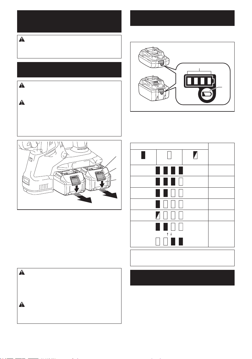
30 ESPAÑOL
DESCRIPCIÓN DEL
FUNCIONAMIENTO
PRECAUCIÓN: Asegúrese siempre de que la
herramienta esté apagada y el cartucho de batería
haya sido extraído antes de realizar cualquier
ajuste o comprobación en la herramienta.
Instalación o extracción del
cartucho de batería
PRECAUCIÓN: Apague siempre la herra-
mienta antes de colocar o quitar el cartucho de
batería.
PRECAUCIÓN: Sujete la herramienta y el car-
tucho de la batería con rmeza al colocar o quitar
el cartucho de batería.Sinosesujetaconrmezala
herramientayelcartuchodebatería,puedeocasio-
nar que se resbalen de sus manos causando daños
alaherramientayalcartuchodebatería,asícomo
lesiones a la persona.
3
2
1
►1.Indicadorrojo2.Botón3.Cartuchodebatería
Paraquitarelcartuchodebatería,deslícelodelaherra-
mientamientrasdeslizaelbotónsobrelapartedelan-
tera del cartucho.
Paracolocarelcartuchodebatería,alineelalengüeta
sobreelcartuchodebateríaconlaranuraenlacarcasa
y deslice en su lugar. Inserte por completo hasta que
sejeensulugarconunpequeñoclic.Sipuedeverel
indicadorrojodelladosuperiordelbotón,estoindica
quenohaquedadojoporcompleto.
PRECAUCIÓN: Introduzca siempre com-
pletamente el cartucho de batería hasta que
el indicador rojo no pueda verse.Sino,podría
accidentalmente salirse de la herramienta y caer al
suelocausandounalesiónaustedoalguienasu
alrededor.
PRECAUCIÓN: No instale el cartucho de
batería a la fuerza. Si el cartucho no se desliza al
interiorfácilmente,sedebeaquenoestásiendo
insertado correctamente.
Indicación de la capacidad restante
de la batería
Únicamente para cartuchos de batería con el
indicador
1
2
►1. Luces indicadoras 2.Botóndevericación
Oprimaelbotóndevericaciónenelcartuchodela
bateríaparaqueindiquelacapacidadrestantedela
batería.Laslucesindicadorasseiluminaránporalgu-
nos segundos.
Luces indicadoras Capacidad
restante
Iluminadas Apagadas Parpadeando
75% a 100%
50% a 75%
25% a 50%
0% a 25%
Cargar la
batería.
Labatería
pudo haber
funcionado
mal.
NOTA: Dependiendo de las condiciones de uso y
latemperaturaambiente,laindicaciónpodrádiferir
ligeramente de la capacidad real.
Sistema de protección para la
herramienta/batería
Laherramientaestáequipadaconunsistemadepro-
teccióndelaherramienta/batería.Estesistemacorta
enformaautomáticaelsuministrodeenergíaalmotor
paraprolongarlavidaútildelaherramientaylabatería.
Laherramientasedetendráautomáticamentedurante
laoperaciónsilaherramientaolabateríasesometena
una de las siguientes condiciones:
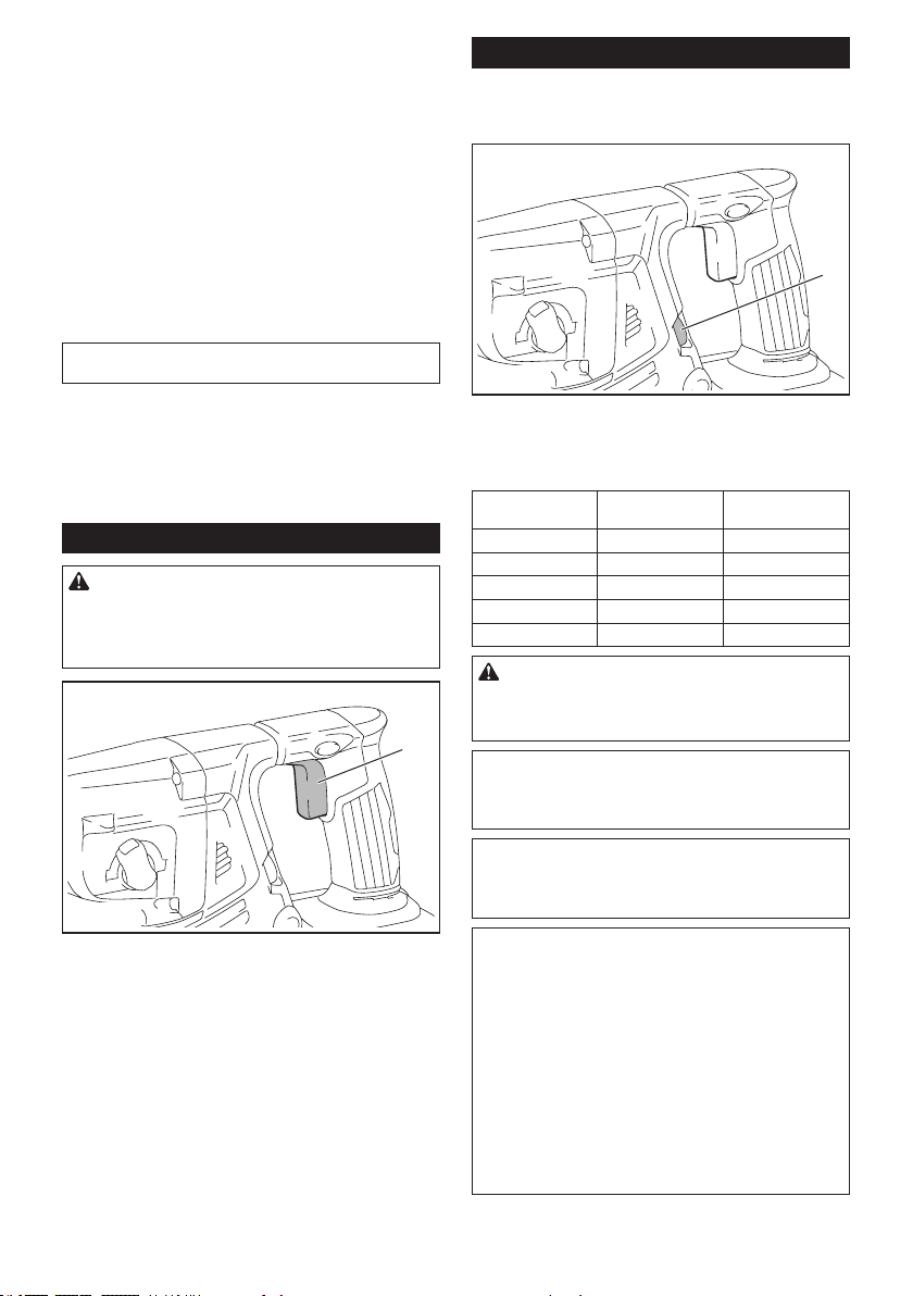
31 ESPAÑOL
Protección contra sobrecarga
Cuandolabateríaseestéutilizandodeunamanera
que cause que consuma una cantidad de corriente
anormalmentealta,laherramientasedetendráautomá-
ticamentesinindicaciónalguna.Enestecaso,apague
laherramientaydetengalaaplicaciónquecausóquela
herramienta se sobrecargara. Luego encienda la herra-
mienta para reiniciarla.
Protección contra
sobrecalentamiento
Cuandolaherramientaolabateríasesobrecalienten,
laherramientasedetendráautomáticamente.Eneste
caso,permitaquelaherramientaylabateríaseenfríen
antes de volver a encender la herramienta.
NOTA: Cuando la herramienta se sobrecaliente, la
lámparaparpadeará.
Protección en caso de
sobredescarga
Cuandolacapacidaddelabateríanoessuciente,la
herramientasedetieneautomáticamente.Enestecaso,
retirelabateríadelaherramientaycárguela.
Accionamiento del interruptor
ADVERTENCIA: Antes de insertar el car-
tucho de batería en la herramienta, compruebe
siempre y cerciórese de que el gatillo interruptor
se acciona debidamente y que vuelve a la posi-
ción “OFF” (apagado) cuando lo suelta.
1
►1. Gatillo interruptor
Paraarrancarlaherramienta,simplementejaleelgatillo
interruptor. La velocidad de la herramienta aumenta
alincrementarlapresiónenelgatillointerruptor.Para
detenerla, suelte el gatillo interruptor.
Cambio de velocidad
Lasrevolucionesygolpesporminutosepuedenajustar
girandoelselectordeajuste.Elselectorestámarcado
del1(velocidadmásbaja)al5(velocidadmásalta).
1
►1.Selectordeajuste
Consultelatablaacontinuaciónparaverlarelación
entreelnúmeroenelselectordeajusteylasrevolucio-
nes y golpes por minuto.
Número Revoluciones por
minuto
Golpes por minuto
5 980 5 000
4 810 4 130
3 640 3 260
2 470 2 400
1 300 1 550
PRECAUCIÓN: No gire el selector de ajuste
cuando la herramienta esté funcionando. De lo
contrario, podría resultar en la pérdida de control
de la herramienta y ocasionar una lesión.
AVISO: Si la herramienta es operada a baja velo-
cidad de forma continua durante un tiempo pro-
longado, el motor se sobrecargará provocando
que la herramienta se averíe.
AVISO: El selector de ajuste de velocidad solo
puede girarse hasta 5 y de regreso a 1. No lo
fuerce más allá de 5 o 1 o la función de ajuste de
velocidad podría dejar de funcionar.
NOTA: Función de rotación suave sin carga (para
los modelos XRH10/XRH11)
Cuandoelselectordeajustedevelocidadestáajus-
tadoen“3”omás,laherramientaautomáticamente
reducelavelocidadavelocidadsincargaande
disminuirlavibraciónenestamodalidad.Cuandola
operacióncomienzaconunapuntacontraconcreto,
los golpes por minuto se incrementan y alcanzan
los números que se muestran en la tabla. Cuando la
temperaturaesbajayhaymenosuidezdegrasa,la
herramientapodríanotenerestafunciónaunconel
motor girando.
Estafunciónnoestarádisponiblecuandoelsistema
derecoleccióndepolvoestéinstalado.
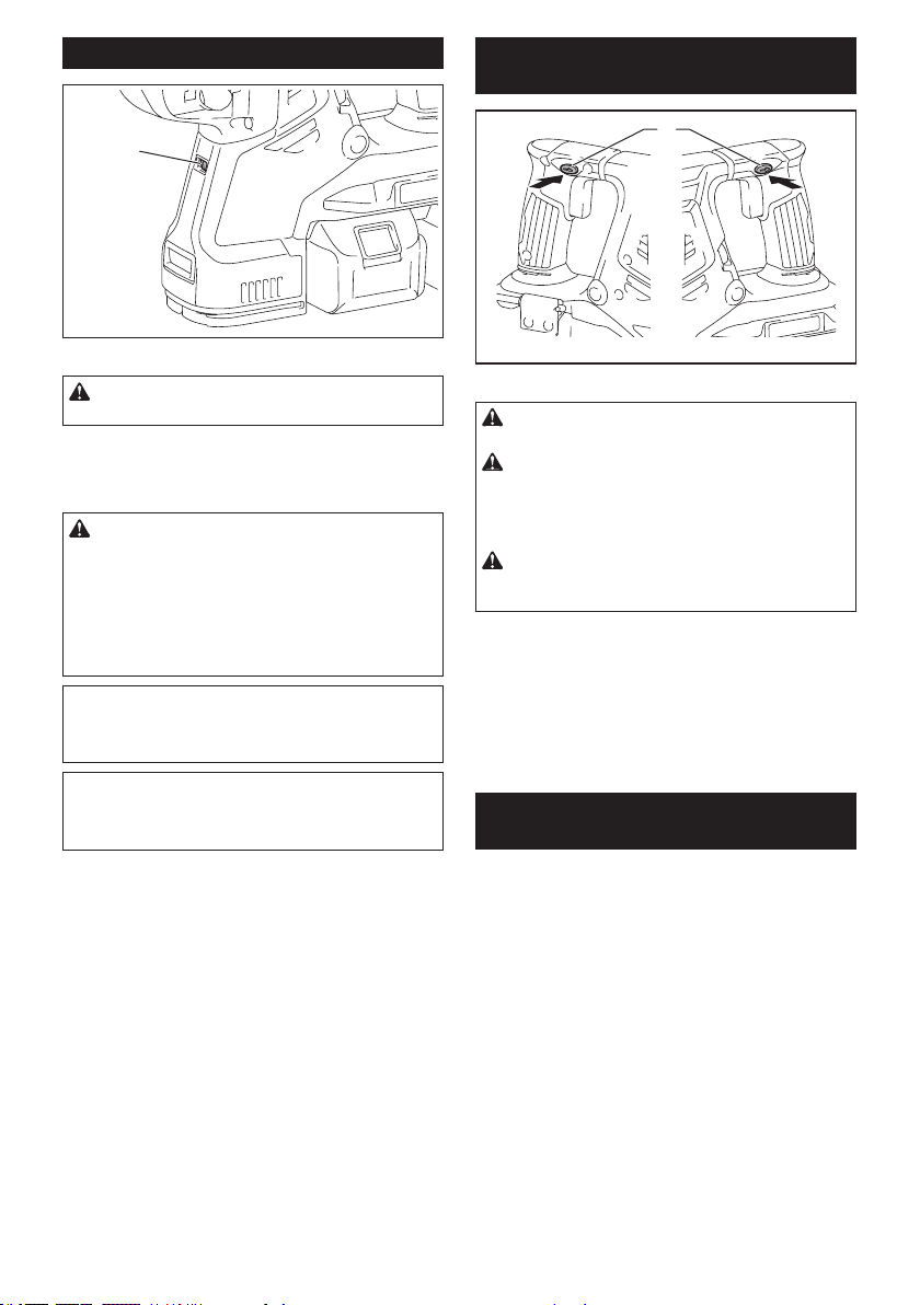
32 ESPAÑOL
Iluminación de la luz delantera
1
►1. Luz
PRECAUCIÓN: No mire a la luz ni vea a la
fuente de luz directamente.
Jale el gatillo interruptor para encender la luz. La luz
continúailuminándosemientrasseestájalandoel
gatillo interruptor. La luz se apaga aproximadamente 10
segundos tras haber liberado el gatillo interruptor.
PRECAUCIÓN: Para los modelos XRH10/
XRH11
Si la lámpara se apaga después de parpadear
durante algunos segundos, la tecnología de
detección de retroalimentación activa o la función
de rotación suave sin carga no está funcionando
correctamente. Solicite la reparación al centro de
servicio Makita de su localidad.
NOTA: Utilice un paño seco para quitar la suciedad
delalentedelalámpara.Tengacuidadodenorayar
lalentedelalámparayaquelailuminaciónpodría
disminuir.
NOTA:Cuandoelsistemaderecoleccióndepolvose
encuentreinstaladoenlaherramienta,lalámparadel
sistemaderecoleccióndepolvoseencenderáenvez
delalámparadelaherramienta.
Accionamiento del conmutador de
inversión de giro
1
AB
►1.Palancadelinterruptordeinversión
PRECAUCIÓN: Conrme siempre la direc-
ción de rotación antes de la operación.
PRECAUCIÓN: Utilice el conmutador de
inversión solamente después de que la herra-
mienta haya parado completamente. Si cambia
ladirecciónderotaciónantesdequelaherramienta
hayaparadopodríadañarla.
PRECAUCIÓN: Cuando no esté utilizando la
herramienta, ponga siempre la palanca del con-
mutador de inversión en la posición neutral.
Estaherramientatieneunconmutadordeinversión
paracambiarladirecciónderotación.Presionela
palancadelconmutadordeinversióndesdeelladoA
paraunarotaciónensentidodelasmanecillasdelreloj
odesdeelladoB,paraunarotaciónensentidoinverso
aldelasmanecillasdelreloj.
Cuandolapalancadelconmutadordeinversiónesté
enlaposiciónneutral,nosepodrájalarelgatillo
conmutador.
Cambio del portabrocas de cambio
rápido para SDS-plus
Para el modelo XRH11
ElportabrocasdecambiorápidoparaSDS-pluspuede
intercambiarsefácilmenteporelportabrocasadaptador
decambiorápido.
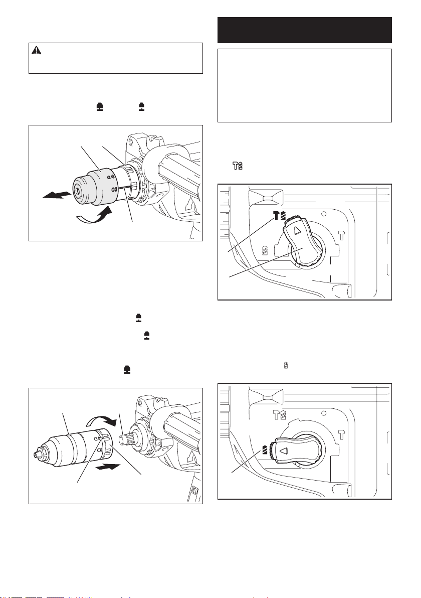
33 ESPAÑOL
Extracción del portabrocas de
cambio rápido para SDS-plus
PRECAUCIÓN:Antesdeextraerelportabro-
casdecambiorápidoparaSDS-plus,asegúresede
retirar la punta.
Sujetelacubiertadecambiodelportabrocasdecam-
biorápidoparaSDS-plusygírelaenladireccióndela
echahastaquelalíneadelacubiertadecambiose
desplacedelsímbolo
alsímbolo . Jale con fuerza
enladireccióndelaecha.
1 2
3
►1.PortabrocasdecambiorápidoparaSDS-plus
2. Cubierta de cambio 3.Líneadelacubiertade
cambio
Instalación del portabrocas
adaptador de cambio rápido
Veriquequelalíneadelportabrocasadaptadorde
cambiorápidomuestreelsímbolo
.Sujetelacubierta
de cambio del portabrocas adaptador de cambio
rápidoyajustelalíneaenelsímbolo
. Coloque el
portabrocasadaptadordecambiorápidoenelejede
laherramienta.Sujetelacubiertadecambiodelporta-
brocasadaptadordecambiorápidoygirelalíneadela
cubiertadecambioalsímbolo
hasta que se pueda
escuchar claramente un clic.
1 2
3
4
►1.Portabrocasadaptadordecambiorápido2.Eje
3.Líneadelacubiertadecambio4. Cubierta de
cambio
Selección del modo de
accionamiento
AVISO: No gire la perilla de cambio de modo de
accionamiento cuando la herramienta esté en
marcha.Estopodríacausardañosalaherramienta.
AVISO: Para evitar un desgaste rápido del meca-
nismo de cambio de modo, asegúrese siempre
de que la perilla de cambio de modo de acciona-
miento se encuentre realmente ubicada en una de
las tres posiciones del modo de accionamiento.
Rotación con percusión
Parataladrarenconcreto,mampostería,etc.,girela
perilladecambiodemododeaccionamientoalsím-
bolo
. Utilice una broca con punta de carburo de
tungsteno (accesorio opcional).
1
2
►1.Rotaciónconpercusión2. Perilla de cambio de
modo de accionamiento
Sólo rotación
Para taladrar en materiales de madera, metal o
plástico,girelaperilladecambiodemododeaccio-
namientoalsímbolo
. Utilice una broca helicoidal o
broca para madera.
1
►1.Sólorotación
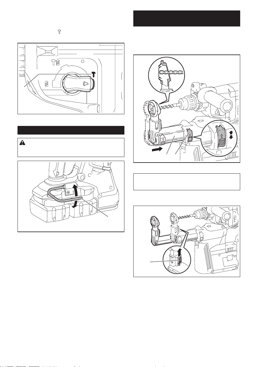
34 ESPAÑOL
Sólo percusión
Paraoperacionesdecincelado,desincrustacióno
demolición,girelaperilladecambiodemododeaccio-
namientoalsímbolo
. Utilice un cincel de punta,
cincelplano,cinceldedesincrustación,etc.
1
►1.Sólopercusión
Gancho
PRECAUCIÓN: Nunca enganche la herra-
mienta en un lugar elevado o en una supercie
potencialmente inestable.
1
►1. Gancho
El gancho resulta conveniente para colgar temporal-
mente la herramienta.
Cuandovayaautilizarelgancho,simplementeleván-
telohastaquequedetrabadoenlaposiciónabierta.
Cuandonolovayaautilizar,siemprebájelohastaque
quedetrabadoenlaposicióncerrada.
Ajuste de la posición de la boquilla
del sistema de recolección de polvo
Accesorio opcional
Empujehaciaadentrolaguíamientrasoprimehacia
arribaelbotóndeajustedelaguíayluegosuelteel
botónenlaposicióndeseada.
1 2
►1.Guía2.Botóndeajustedelaguía
NOTA:Antesdeajustarlaposicióndelaboquilla,
libere totalmente la boquilla hacia adelante opri-
miendohaciaarribaelbotóndeajustedelaguía.
Sivaainstalarunabrocalarga,extiendalaguíaopri-
miendohaciaarribaelbotóndeextensión.
1
►1.Botóndeextensión
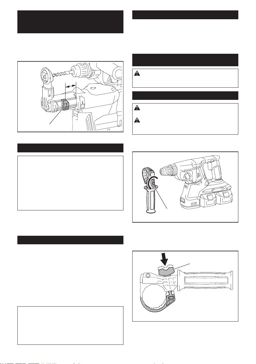
35 ESPAÑOL
Ajuste de la profundidad de
perforación del sistema de
recolección de polvo
Accesorio opcional
Desliceelbotóndeajustedeprofundidadhastala
posicióndeseadamientraslooprimehaciaarriba.La
distancia(A)eslaprofundidaddeperforación.
A
1
►1.Botóndeajustedeprofundidad
Limitador de torsión
AVISO: En cuanto el limitador de torsión se
accione, apague de inmediato la herramienta.
Estoayudaráaevitareldesgasteprematurodela
herramienta.
AVISO: Las brocas tales como las de sierra
perforadora, las cuales tienden a atorarse o
engancharse fácilmente en el agujero, no son
adecuadas para esta herramienta. Esto es debido
aquepuedenprovocarqueellimitadordetorsiónse
accione con demasiada frecuencia.
Ellimitadordetorsiónseaccionaráunavezquese
alcanceunciertoniveldetorsión.Elmotorsedesen-
gancharádelejedesalida.Cuandoestosuceda,la
brocadejarádegirar.
Funcionamiento electrónico
Laherramientaestáequipadaconfuncioneselectróni-
casparafacilitarlaoperación.
• Controldevelocidadconstante
Lafuncióndecontroldevelocidadpermiteuna
rotaciónconstanteindependientementedelas
condiciones de carga.
• Tecnologíadedetecciónderetroalimentación
activa(paralosmodelosXRH10/XRH11)
Silaherramientagiraalaaceleraciónpredetermi-
nadadurantelaoperación,elmotorserádetenido
forzadamente para reducir la carga en la muñeca.
NOTA:Estafunciónnoservirásilaaceleraciónno
alcanza la predeterminada al girar la herramienta.
NOTA:Silapuntagiraalaaceleraciónpredetermi-
nadaduranteelcincelado,ladesincrustaciónola
demolición,elmotorserádetenidoforzadamente.En
estecaso,suelteelgatillointerruptoryluegojálelo
para reiniciar la herramienta.
Freno eléctrico
Laherramientaestáequipadaconunfrenoeléctrico.Si
la herramienta falla constantemente en detenerse tras
soltar el gatillo interruptor, lleve la herramienta a mante-
nimiento a un centro de servicio Makita.
MONTAJE
PRECAUCIÓN:
Asegúrese siempre de que la herra-
mienta esté apagada y el cartucho de batería haya sido
extraído antes de realizar cualquier trabajo en la misma.
Empuñadura lateral (mango auxiliar)
PRECAUCIÓN: Utilice siempre la empuña-
dura lateral para garantizar una operación segura.
PRECAUCIÓN: Después de instalar o ajustar
la empuñadura lateral, asegúrese de que quede
rmemente asegurada.
Parainstalarlaempuñaduralateral,sigalospasosacontinuación.
1.
Aojeeltornillodemariposaenlaempuñaduralateral.
1
►1.Tornillodemariposa
2.
Instale la empuñadura lateral mientras presiona el tor-
nillo de mariposa de modo que las ranuras en la empuñadura
encajenenlasprotuberanciasdelcilindrodelaherramienta.
1
►1.Tornillodemariposa
3. Aprieteeltornillodemariposaparaasegurar
laempuñadura.Laempuñadurapuedejarseenel
ángulodeseado.
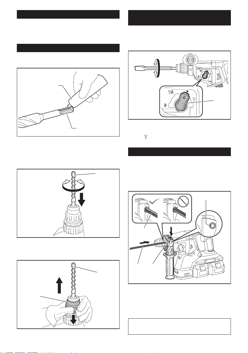
36 ESPAÑOL
Grasa
Apliquepreviamenteunapequeñacantidaddegrasa(alre-
dedor de 0,5 g - 1 g) en el extremo de la espiga de la broca.
Lalubricacióndelportabrocasaseguraunacciona-
mientosuaveyunavidaútilmáslarga.
Instalación o extracción de la broca
Limpie el extremo de la espiga de la broca y aplique
grasa antes de instalar la broca.
1
2
►1. Extremo de la espiga 2. Grasa
Inserte la broca en la herramienta. Gire la broca y
empújelahaciaadentrohastaquequedeenganchada.
Después de instalar la broca, asegúrese siempre de que la broca
quedeaseguradaensulugarintentandojalarlahaciaafuera.
1
►1. Broca
Paraextraerlabroca,jalehastaabajolacubiertadel
portabrocasyjalelabrocahaciaafuera.
1
2
►1. Broca 2. Cubierta del portabrocas
Ángulo del cincel (durante el cincelado,
desincrustación o demolición)
Elcincelpuedejarseenelángulodeseado.Para
cambiarelángulodelcincel,girelaperilladecambiode
mododeaccionamientoalsímboloO.Gireelcincelal
ángulodeseado.
1
►1. Perilla de cambio de modo de accionamiento
Gire la perilla de cambio de modo de accionamiento al
símbolo
. Luego asegúrese de que el cincel quede
aseguradoensulugargirándololigeramente.
Calibrador de profundidad
Elcalibradordeprofundidadsirveparaperforaroricios
de profundidad uniforme.
Oprimaymantengaoprimidoelbotóndebloqueoy
luegoinserteelcalibradordeprofundidadeneloricio
hexagonal.Asegúresedequeelladodentadodelcali-
brador de profundidad quede de frente a la marca.
12
4
3
►1. Calibrador de profundidad 2.Botóndebloqueo
3. Marca 4. Lado dentado
Ajusteelcalibradordeprofundidadmoviéndolohacia
atrásyhaciaadelantemientrasoprimeelbotóndeblo-
queo.Despuésdeajustarlo,suelteelbotóndebloqueo
para bloquear el calibrador de profundidad.
NOTA:Asegúresedequeelcalibradordeprofundi-
dad no toque el cuerpo principal de la herramienta al
momentodejarlo.
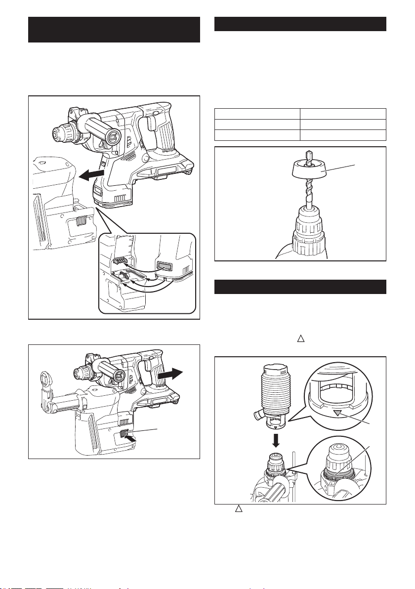
37 ESPAÑOL
Instalación o extracción del sistema
de recolección de polvo
Accesorio opcional
Parainstalarelsistemaderecoleccióndepolvo,inserte
laherramientaenelsistemaderecoleccióndepolvo
hasta que llegue al fondo y quede asegurado en su
lugar con un pequeño doble clic.
Paraextraerelsistemaderecoleccióndepolvo,jalela
herramientamientrasoprimeelbotóndedesbloqueo.
1
►1.Botóndedesbloqueo
Contenedor de polvo
Accesorio opcional
Utilice el contenedor de polvo para evitar que el polvo
caiga sobre la herramienta y sobre usted al realizar
operacionesdeperforaciónporencimadesucabeza.
Fijeelcontenedordepolvoenlapuntatalcomose
muestraenlailustración.Eltamañodelaspuntasen
lasqueelcontenedordepolvopuedejarseeselque
seindicaacontinuación.
Modelo Diámetrodelapunta
Contenedor de polvo 5 6mm(1/4″)-14,5mm(9/16″)
Contenedor de polvo 9 12mm(15/32″)-16mm(5/8″)
1
►1. Contenedor de polvo
Juego contenedor de polvo
Accesorio opcional
Antesdeinstalareljuegocontenedordepolvo,extraiga
la punta de la herramienta en caso de estar instalada.
Instaleeljuegocontenedordepolvoenlaherramienta
demaneraqueelsímbolo
en el contenedor de
polvo quede alineado con la ranura en la herramienta.
1
2
►1. símbolo2. Ranura
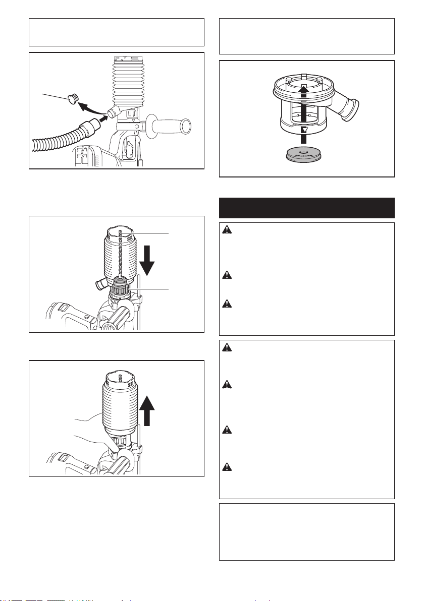
38 ESPAÑOL
NOTA:Siconectaunaaspiradoraaljuegocontene-
dor de polvo, retire la tapa guardapolvos antes de
conectarla.
1
►1.Tapaguardapolvos
Paraextraereljuegocontenedordepolvo,retirela
puntamientrasjalalacubiertadelportabrocasenla
direccióndelaecha.
1
2
►1. Punta 2. Cubierta del portabrocas
Tomeelcontenedordepolvodesdelaraízysáquelo.
NOTA: Si la tapa llega a salirse del contenedor de
polvo,fíjelaconsuladoimpresoorientadohacia
arribademaneraquelaranuraenlatapaencajeen
la periferia interior del accesorio.
OPERACIÓN
PRECAUCIÓN: Utilice siempre la empuña-
dura lateral (mango auxiliar) y sujete rmemente
la herramienta tanto de la empuñadura lateral
como del mango del interruptor durante las
operaciones.
PRECAUCIÓN: Asegúrese siempre de que
la pieza de trabajo quede asegurada antes de la
operación.
PRECAUCIÓN: No jale hacia afuera la herra-
mienta con demasiada fuerza aun si la punta
se atora. La pérdida de control podría causar
lesiones.
PRECAUCIÓN: El sistema de recolección de
polvo está diseñado para perforar en concreto
únicamente. No utilice el sistema de recolección
de polvo para perforar en metal ni en madera.
PRECAUCIÓN: Cuando vaya a utilizar la
herramienta con el sistema de recolección de
polvo, asegúrese de colocar el ltro en el sistema
de recolección de polvo para evitar la inhalación
de polvo.
PRECAUCIÓN: Antes de utilizar el sistema
de recolección de polvo, verique que el ltro no
esté dañado.Elnohacerlopodríacausarlainhala-
cióndepolvo.
PRECAUCIÓN: El sistema de recolección
de polvo recolecta el polvo que se genera en un
volumen considerable, sin embargo, es imposible
recolectarlo todo.
AVISO: No utilice el sistema de recolección de
polvo para taladrado con corona ni cincelado.
AVISO: No utilice el sistema de recolección de
polvo para perforar en concreto húmedo ni lo
utilice en entornos mojados. El hacerlo podría
causar averías.
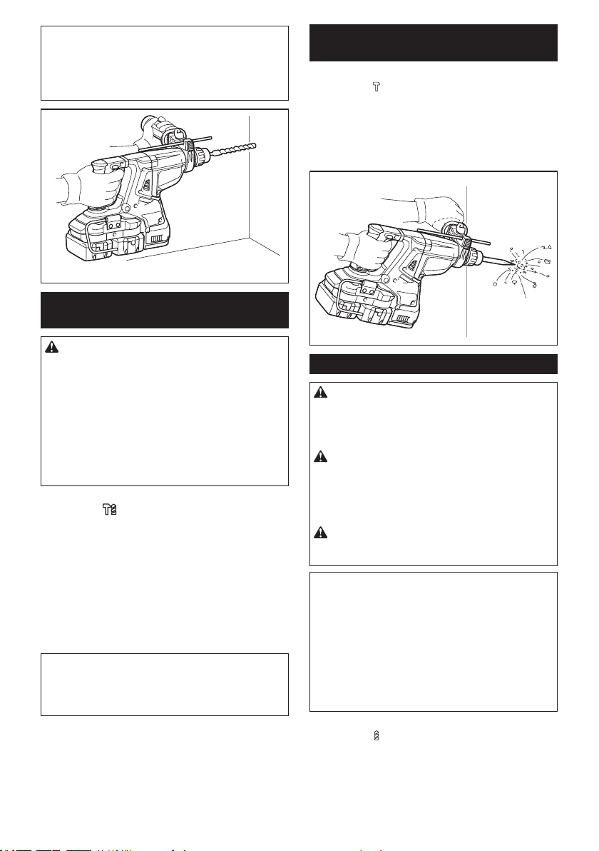
39 ESPAÑOL
NOTA:Sielcartuchodebateríaseencuentraabaja
temperatura,laherramientapodríanoalcanzarsu
máximacapacidad.Enestecaso,calienteelcartucho
debateríausandolaherramientasincargadurante
unratoandelograrquelaherramientaalcancesu
máximacapacidad.
Operación de taladrado con
percusión
PRECAUCIÓN: En el momento de comenzar
apenetrar,cuandoseobstruyeeloricioconviru-
tasypartículas,ocuandosetopacontravarillas
derefuerzodeconcreto,seejerceunatremenday
repentinafuerzadetorsiónsobrelaherramienta/
broca. Utilice siempre la empuñadura lateral
(mango auxiliar) y sujete rmemente la herra-
mienta tanto de la empuñadura lateral como del
mango del interruptor durante las operaciones. El
no hacerlo puede provocar la pérdida de control de
la herramienta y potencialmente ocasionar lesiones
graves.
Ajustelaperilladecambiodemododeaccionamiento
enelsímbolo
.
Coloquelabrocadondedeseehacerelagujeroyluego
jaleelgatillointerruptor.Nofuercelaherramienta.Los
mejoresresultadosseobtienenconunaligerapresión.
Mantengalaherramientaenposiciónyevitequese
desliceysesalgadelagujero.
Noapliquemáspresióncuandoelagujeroseobstruya
conastillasopartículas.Envezdeesto,hagafuncionar
laherramientasinpresiónyluegoretireparcialmente
labrocadelagujero.Repitiendoestovariasveces,el
agujeroselimpiaráysepodráreanudareltaladradode
manera normal.
NOTA: Es posible que se produzca excentricidad en
larotacióndelabrocaaloperarlaherramientasin
carga.Laherramientasecentraráautomáticamente
durantelaoperación.Estonoafectarálaprecisiónen
el taladrado.
Cincelado/desincrustación/
demolición
Ajustelaperilladecambiodemododeaccionamiento
enelsímbolo
.
Sujetelaherramientarmementeconambasmanos.
Enciendalaherramientayapliqueunaligerapresión
sobre ella de manera que no rebote de forma descon-
trolada.
Aplicarmuchapresiónsobrelaherramientanoincre-
mentarálaeciencia.
Taladrado en madera o metal
PRECAUCIÓN: Sujete rmemente la herra-
mienta y tenga cuidado cuando la broca de tala-
dro comience a penetrar en la pieza de trabajo. La
fuerzaejercidaenlaherramienta/brocadetaladroal
momentodelapenetraciónesenorme.
PRECAUCIÓN: Para extraer una broca de
taladro atorada, basta simplemente con ajustar el
interruptor de inversión en rotación inversa para
hacerla retroceder. Sin embargo, la herramienta
puede retroceder bruscamente si no la sujeta con
rmeza.
PRECAUCIÓN: Asegure siempre las piezas
de trabajo con un tornillo de banco o dispositivo
de sujeción similar.
AVISO: Nunca use la “rotación con percusión”
cuando el portabrocas adaptador esté instalado
en la herramienta.Estopodríacausardañosal
portabrocas adaptador.
Asimismo,elportabrocasadaptadorpodríasalirseal
invertirlarotacióndelaherramienta.
AVISO: Ejercer una presión excesiva sobre la
herramienta no hará que consiga taladrar más
rápido.Dehecho,unapresiónexcesivasólologrará
dañar la punta de la broca de taladro, reducir el des-
empeño y acortar la vida útil de la herramienta.
Ajustelaperilladecambiodemododeaccionamiento
enelsímbolo
.
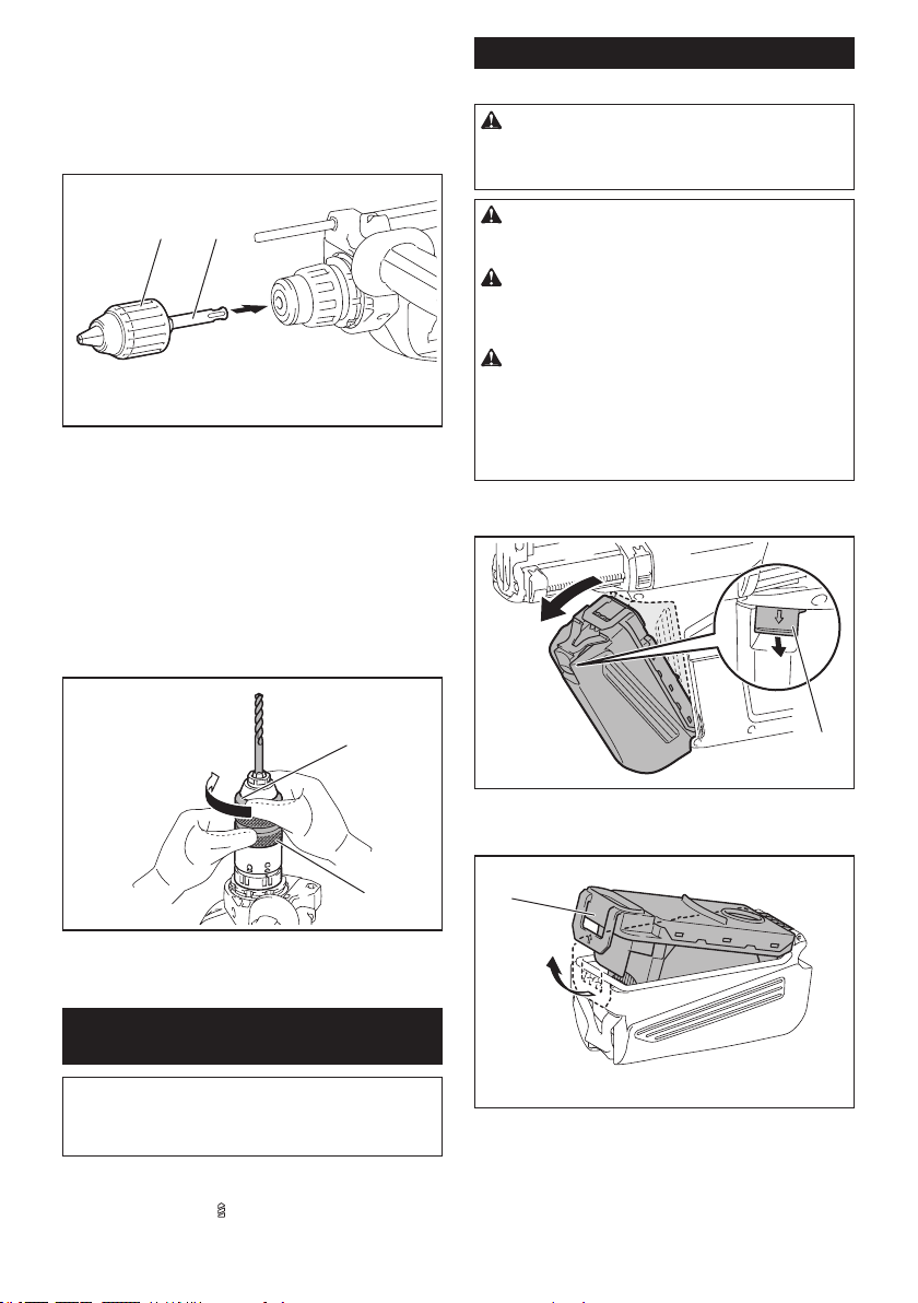
40 ESPAÑOL
Para los modelos XRH08/XRH10
Accesorio opcional
Fijeeladaptadordemandrilenunportabrocasadaptadorsin
llaveenelquepuedainstalarseuntornilloquemida1/2″-20,
ydespuésinstálelosenlaherramienta.Cuandoloinstale,
consultelasección“Instalaciónoextraccióndelabroca”.
1
2
►1. Portabrocas adaptador sin llave 2.Adaptadorde
mandril
Para el modelo XRH11
Utiliceelportabrocasadaptadordecambiorápidocomo
equipoestándar.Cuandoloinstale,consultelasección
“CambiodelportabrocasdecambiorápidoparaSDS-plus”.
Sostenga el anillo y gire el mandril en sentido inverso al de
lasmanecillasdelrelojparaabrirlasmordazasdelportabro-
cas. Coloque la punta en el mandril hasta que llegue al tope.
Sostengaelanillormementeygireelmandrilenelsentido
delasmanecillasdelrelojparaapretarelportabrocas.
1
2
►1. Mandril 2.Anillo
Para extraer la punta, sostenga el anillo y gire el man-
drilensentidoinversoaldelasmanecillasdelreloj.
Taladrado con punta de corona de
diamante
AVISO: Si realiza operaciones de taladrado con
punta de corona de diamante usando la acción de
“rotación con percusión”, la punta de corona de
diamante podría dañarse.
Cuando realice operaciones de taladrado con punta
decoronadediamante,ajustesiemprelapalancade
cambioenlaposición
parautilizarlaacción“sólo
rotación”.
Eliminación del polvo
Accesorio opcional
PRECAUCIÓN: Asegúrese siempre de que la
herramienta esté apagada y el cartucho de batería
haya sido extraído antes de realizar cualquier
trabajo en la misma.
PRECAUCIÓN: Cuando vaya a proceder a
eliminar el polvo, asegúrese de usar una máscara
contra polvo.
PRECAUCIÓN: Vacíe la caja para polvo regu-
larmente antes de que ésta se llene. El no hacerlo
podríareducireldesempeñodelarecolecciónde
polvoycausarlainhalacióndepolvo.
PRECAUCIÓN: El desempeño de la recolec-
ción de polvo se verá reducido si el ltro en la
caja para polvo llega a obstruirse. Como referen-
cia, reemplace el ltro con uno nuevo después de
aproximadamente 200 veces que la caja se haya
llenado de polvo.Elnohacerlopodríacausarla
inhalacióndepolvo.
1. Extraigalacajaparapolvomientraspresiona
haciaabajolapalancadelacajaparapolvo.
1
►1. Palanca
2. Abralacubiertadelacajaparapolvo.
1
►1. Cubierta
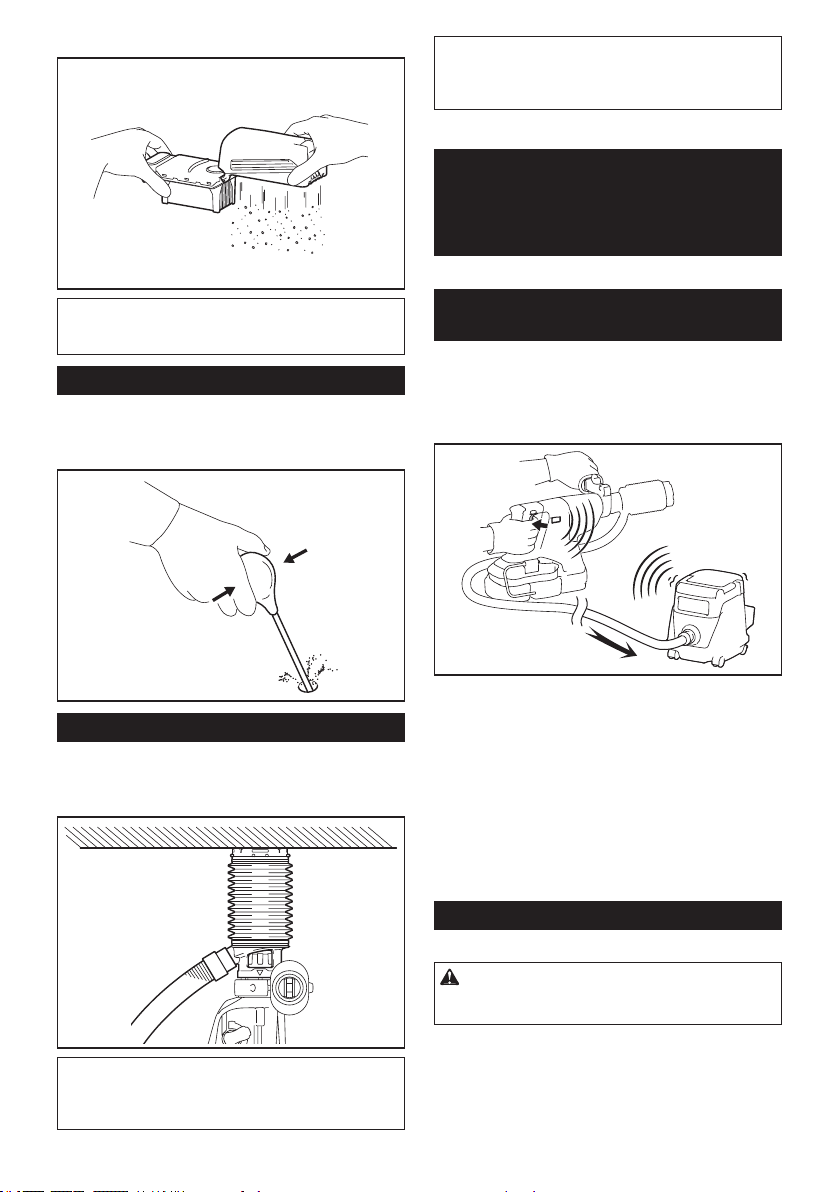
41 ESPAÑOL
3. Elimineelpolvoyluegolimpieelltro.
AVISO:
Cuando limpie el ltro, evite tocarlo con un
cepillo u objeto similar, ni sople aire comprimido al
ltro. El hacerlo podría causar daños al ltro.
Soplador
Accesorio opcional
Despuésdeperforarelagujero,utiliceelsopladorpara
limpiarelpolvodelagujero.
Uso del juego contenedor de polvo
Accesorio opcional
Fijeeljuegocontenedordepolvocontraeltecho
cuando opere la herramienta.
AVISO:
No utilice el juego contenedor de polvo cuando
perfore en metal o un material similar. Esto podría dañar el
juego contenedor de polvo debido al calor producido por
las pequeñas partículas de polvo de metal o material similar.
AVISO: No instale ni extraiga el juego contene-
dor de polvo con la broca instalada en la herra-
mienta. Esto podría dañar el juego contenedor de
polvo y causar la ltración de polvo.
FUNCIÓN DE
ACTIVACIÓN
INALÁMBRICA
Accesorio opcional para los modelos XRH10/XRH11
Lo que puede hacer con la función
de activación inalámbrica
Lafuncióndeactivacióninalámbricapermiteunaope-
raciónlimpiaycómoda.Siconectaalaherramienta
unaaspiradoracompatible,podráhacerqueésta
funcioneautomáticamentealactivarelinterruptordela
herramienta.
Parahacerusodelafuncióndeactivacióninalámbrica,
tenga preparado lo siguiente:
• Unaunidadinalámbrica(accesoriosopcionales)
• Unaaspiradoracompatibleconlafunciónde
activacióninalámbrica
Acontinuaciónsepresentaladescripcióngeneraldel
ajustedelafuncióndeactivacióninalámbrica.Consulte
cadasecciónparaverlosprocedimientosadetalle.
1. Instalacióndelaunidadinalámbrica
2. Registro de la herramienta para la aspiradora
3. Iniciodelafuncióndeactivacióninalámbrica
Instalación de la unidad inalámbrica
Accesorio opcional
PRECAUCIÓN: Coloque la herramienta sobre
una supercie plana y estable cuando vaya a
instalar la unidad inalámbrica.
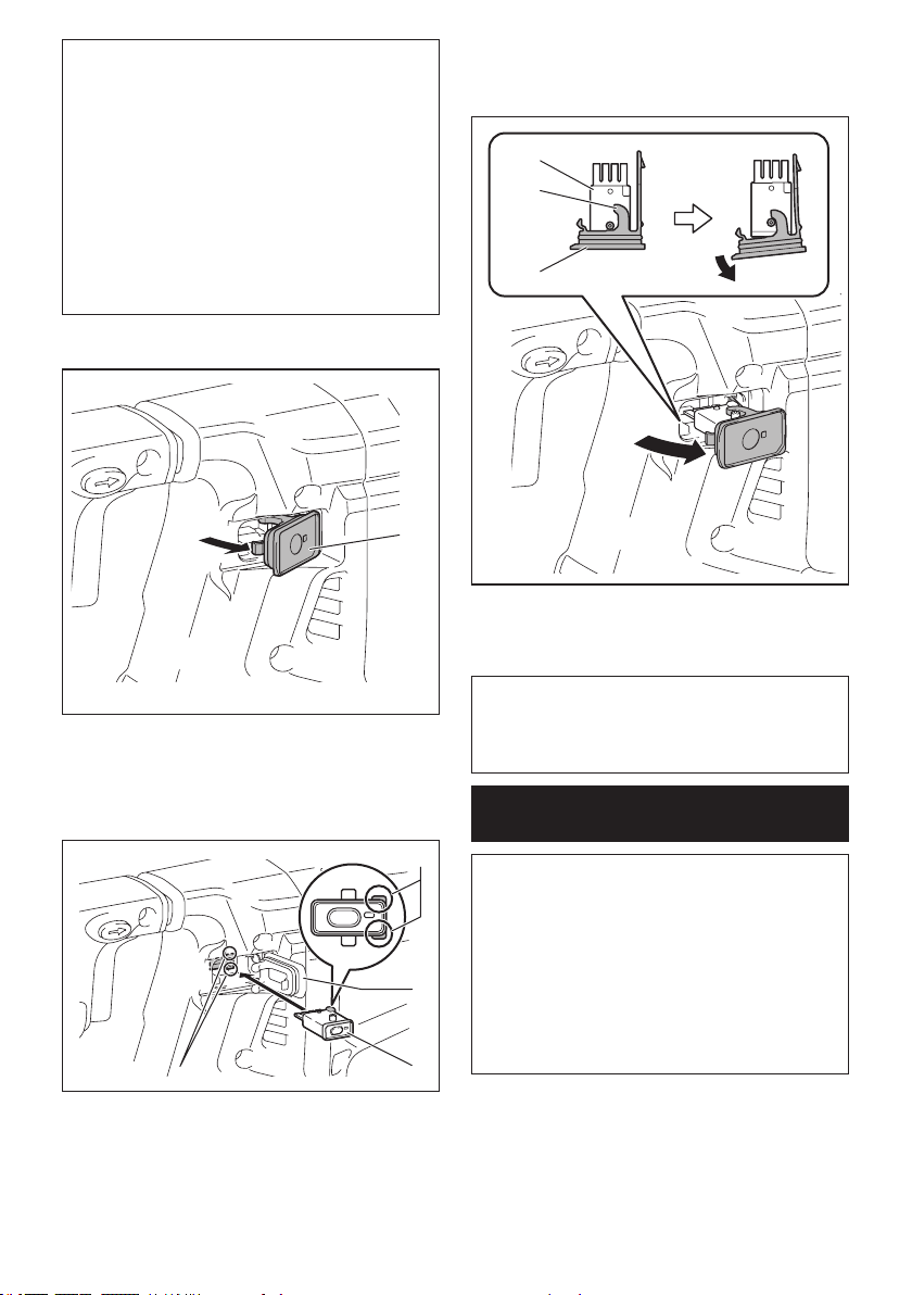
42 ESPAÑOL
AVISO: Limpie el polvo y la suciedad en la herra-
mienta antes de instalar la unidad inalámbrica.
Elpolvoolasuciedadpodríancausarunaavería
si llegan a introducirse en la ranura de la unidad
inalámbrica.
AVISO: Para evitar una avería a causa de la elec-
tricidad estática, toque un material de descarga
de electricidad estática, tal como una pieza metá-
lica de la herramienta antes de levantar la unidad
inalámbrica.
AVISO: Cuando vaya a instalar la unidad inalám-
brica, asegúrese siempre de que ésta sea inser-
tada en la dirección correcta y que la tapa esté
completamente cerrada.
1. Abralatapaenlaherramientatalcomosemues-
traenlailustración.
1
►1.Tapa
2. Insertelaunidadinalámbricaenlaranurayluego
cierre la tapa.
Cuandoinsertelaunidadinalámbrica,alineelaspartes
salientesconlaspartescóncavasenlaranura.
3
2
1
4
►1.Unidadinalámbrica2. Parte saliente 3.Tapa
4.Partecóncava
Cuandoextraigalaunidadinalámbrica,abralatapa
lentamente. Los ganchos en la parte posterior de la
tapalevantaránlaunidadinalámbricamientrasusted
jalahaciaarribalatapa.
1
2
3
►1.Unidadinalámbrica2. Gancho 3.Tapa
Unavezextraídalaunidadinalámbrica,guárdelaenel
estuche suministrado o en un contenedor libre de elec-
tricidadestática.
AVISO: Use siempre los ganchos en la parte
posterior de la tapa cuando extraiga la unidad
inalámbrica.Silosganchosnosujetanlaunidad
inalámbrica,cierrelatapaporcompletoyvuelvaa
abrirla lentamente.
Registro de la herramienta para la
aspiradora
NOTA: Para el registro de la herramienta, se requiere
unaaspiradoraMakitacompatibleconlafunciónde
activacióninalámbrica.
NOTA:Terminedeinstalarlaunidadinalámbricaen
la herramienta antes de comenzar con el registro de
la herramienta.
NOTA:Duranteelregistrodelaherramienta,nojale
el gatillo interruptor ni active el interruptor de encen-
dido en la aspiradora.
NOTA: Consulte también el manual de instrucciones
de la aspiradora.
Sideseaactivarlaaspiradorajuntoconelinterruptor
de la herramienta, termine antes con el registro de la
herramienta.
1. Instalelasbateríasenlaaspiradorayenla
herramienta.
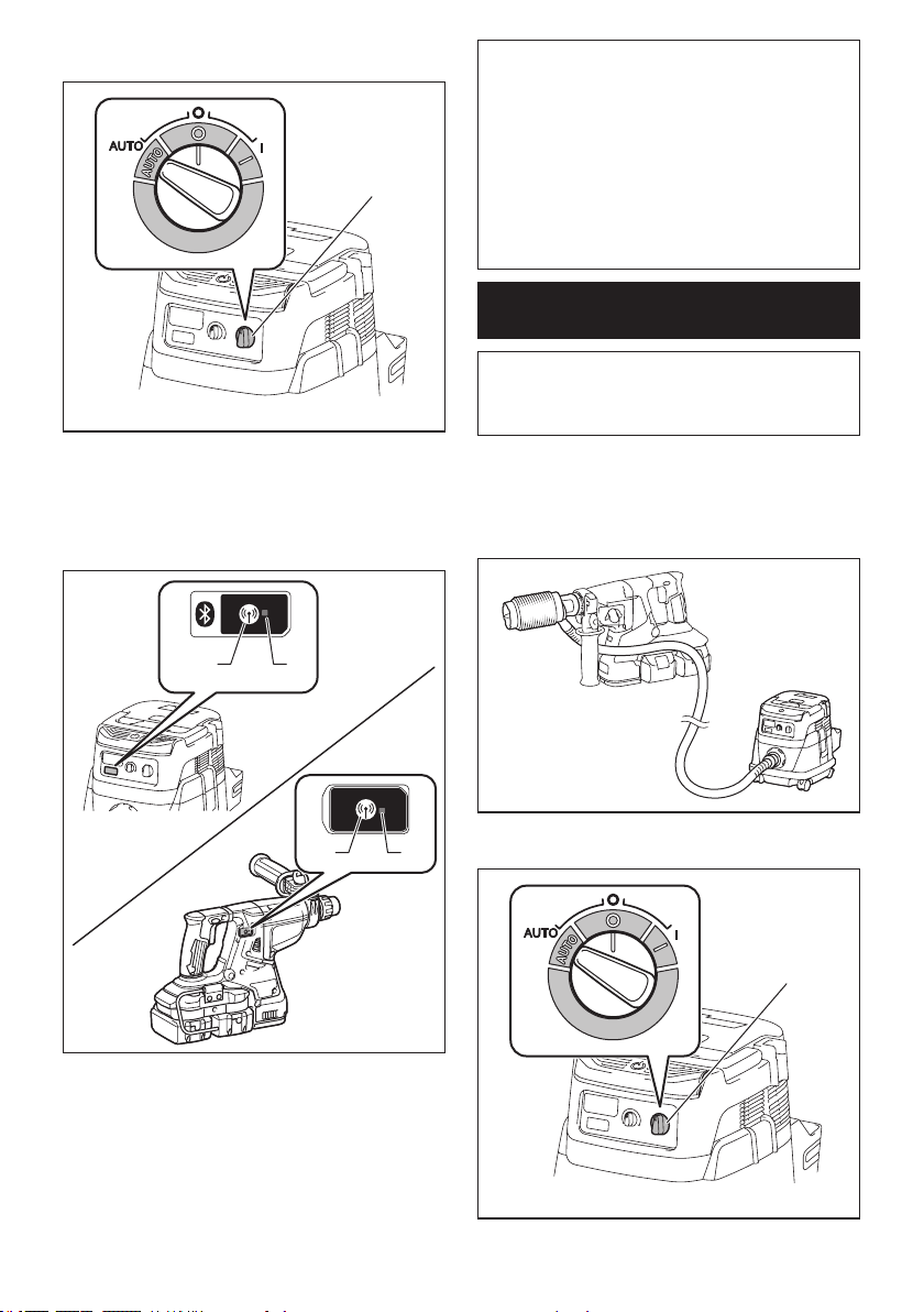
43 ESPAÑOL
2. Ajusteelinterruptordemodoenesperaenlaaspi-
radoraen“AUTO”.
1
►1. Interruptor de modo en espera
3. Oprimaelbotóndeactivacióninalámbricaenla
aspiradora durante 3 segundos hasta que la luz indica-
doradeactivacióninalámbricaparpadeeenverde.Y
luegooprimaelbotóndeactivacióninalámbricaenla
herramienta de la misma manera.
1 2
1 2
►1.Botóndeactivacióninalámbrica2. Luz indica-
doradeactivacióninalámbrica
Si la aspiradora y la herramienta han sido conectadas
exitosamente,laslucesindicadorasdeactivaciónina-
lámbricaseencenderánenverdedurante2segundosy
comenzaránaparpadearenazul.
NOTA:Laslucesindicadorasdeactivacióninalám-
bricaterminaránparpadeandoenverdedespuésde
unlapsode20segundos.Oprimaelbotóndeacti-
vacióninalámbricaenlaherramientamientraslaluz
indicadoradeactivacióninalámbricaenlaaspiradora
estéparpadeando.Silaluzindicadoradeactivación
inalámbricanoparpadeaenverde,oprimaelbotón
deactivacióninalámbricaduranteunlapsobrevey
vuelva a mantenerlo oprimido.
NOTA:Cuandorealicedosomásregistrosdela
herramienta para una aspiradora, termine el registro
de la herramienta de uno en uno.
Inicio de la función de activación
inalámbrica
NOTA:Termineconelregistrodelaherramientapara
laaspiradoraantesdelaactivacióninalámbrica.
NOTA: Consulte también el manual de instrucciones
de la aspiradora.
Después de registrar una herramienta en la aspiradora,
estaúltimaseactivaráautomáticamentejuntoconel
interruptor de la herramienta.
1. Instalelaunidadinalámbricaenlaherramienta.
2.
Conecte la manguera de la aspiradora a la herramienta.
3. Ajusteelinterruptordemodoenesperaenlaaspi-
radoraen“AUTO”.
1
►1. Interruptor de modo en espera
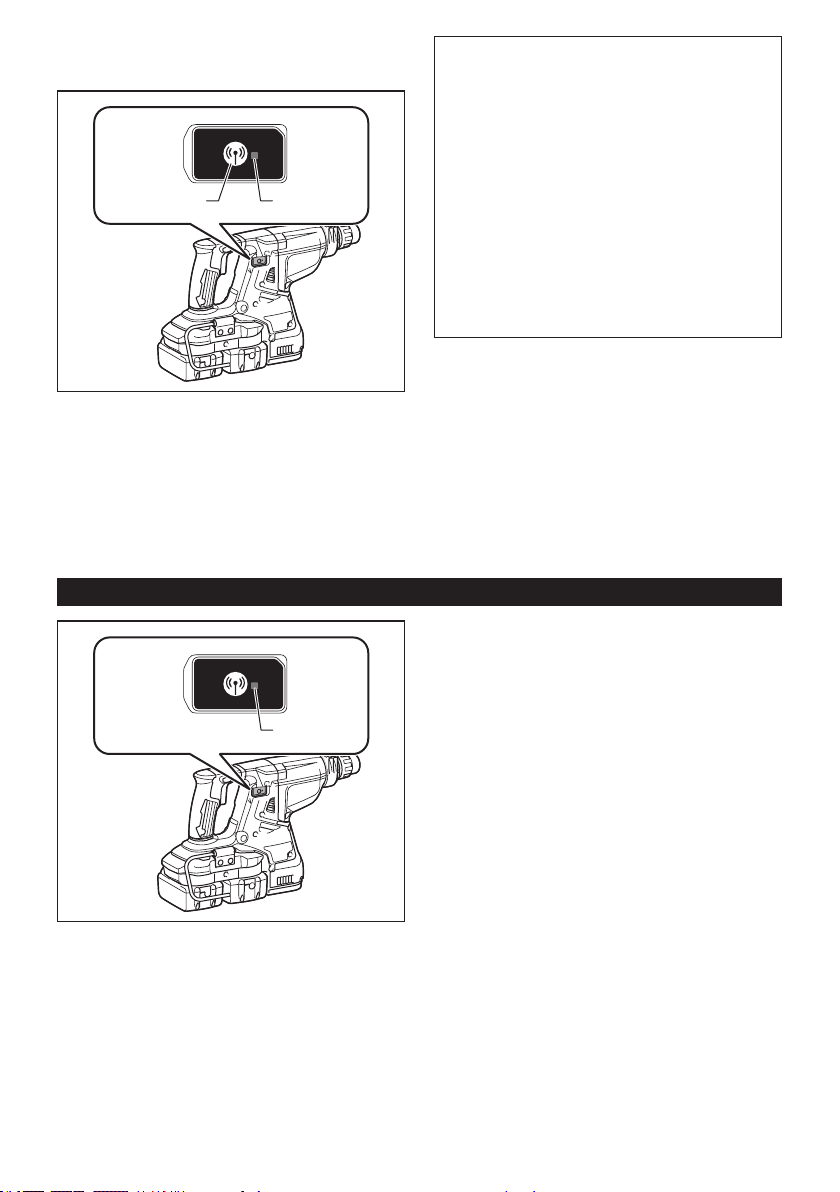
44 ESPAÑOL
4. Oprimaelbotóndeactivacióninalámbricaenla
herramienta durante un lapso breve. La luz indicadora
deactivacióninalámbricaparpadearáenazul.
1 2
►1.Botóndeactivacióninalámbrica2. Luz indica-
doradeactivacióninalámbrica
5. Jale el gatillo interruptor de la herramienta.
Veriquequelaaspiradorafuncionemientrasjalael
gatillo interruptor.
Paradetenerlaactivacióninalámbricadelaaspira-
dora,oprimaelbotóndeactivacióninalámbricaenla
herramienta.
NOTA:Laluzindicadoradeactivacióninalámbricaen
laherramientadejarádeparpadearenazulcuando
nohayaoperacióndurante2horas.Enestecaso,
ajusteelinterruptordemodoenesperaenlaaspi-
radoraen“AUTO”yoprimaelbotóndeactivación
inalámbricaenlaherramientanuevamente.
NOTA:Laaspiradorafuncionará/detendráconun
retraso.Existiráundesfasecuandolaaspiradora
detectelaactivacióndelinterruptordelaherramienta.
NOTA:Ladistanciadetransmisióndelaunidad
inalámbricapodrávariarenfuncióndellugarylas
circunstancias de los alrededores.
NOTA:Cuandodosomásherramientasestén
registradasenunaaspiradora,estaúltimapodrá
comenzarafuncionarinclusosiustednojalaelgatillo
interruptordebidoaqueotrousuarioestáutilizando
lafuncióndeactivacióninalámbrica.
Descripción del estado de la luz indicadora de activación inalámbrica
1
►1.Luzindicadoradeactivacióninalámbrica
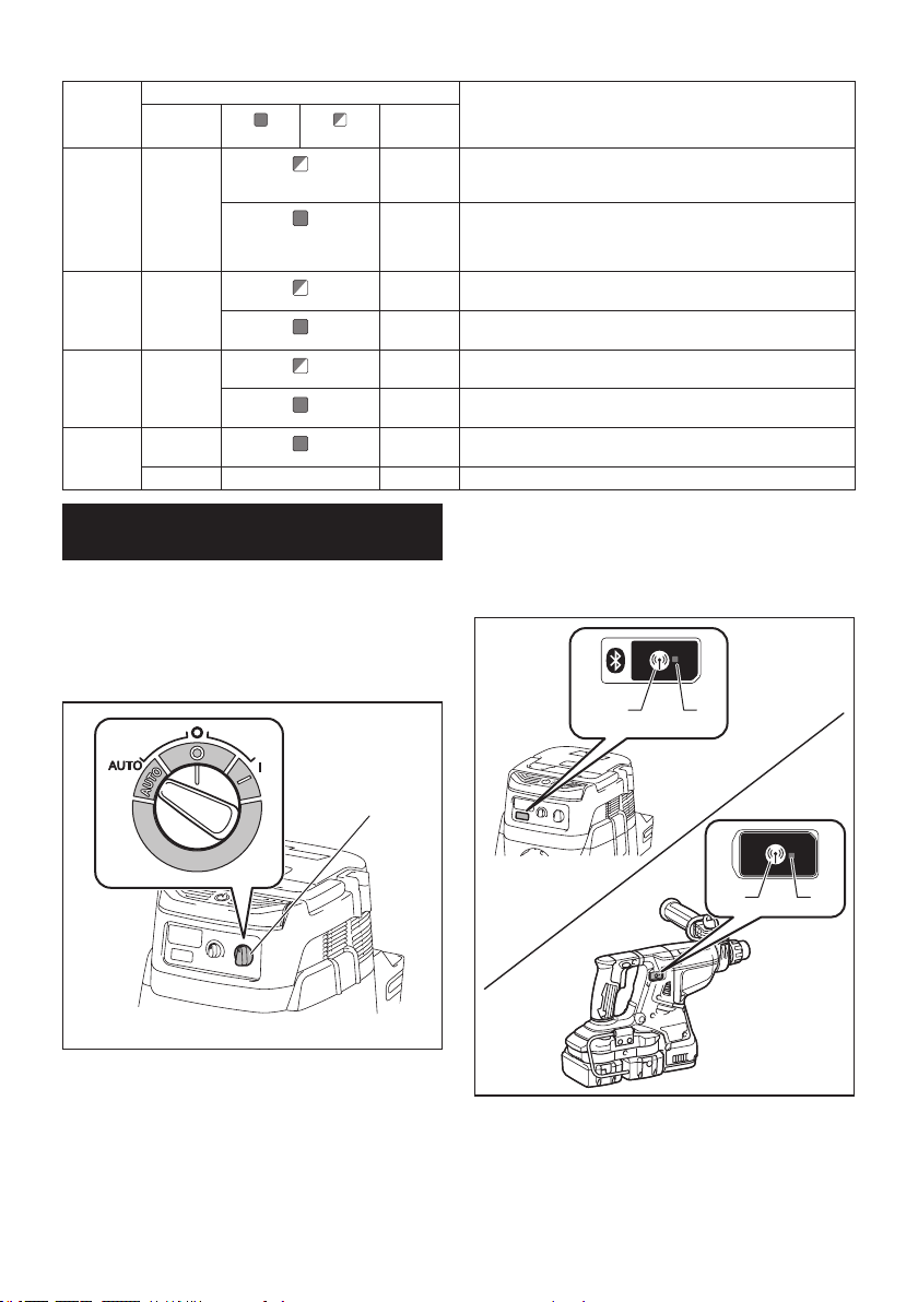
45 ESPAÑOL
Laluzindicadoradeactivacióninalámbricamuestraelestadodelafuncióndeactivacióninalámbrica.Consultela
tablaacontinuaciónparaverquésignicaelestadodelaluzindicadora.
Estado Luz indicadora de activación inalámbrica Descripción
Color
Encendida
Parpadeando
Duración
En espera Azul
2 horas Laactivacióninalámbricadelaaspiradoraestádisponible.La
luzseapagaráautomáticamentecuandonoserealiceninguna
operacióndurante2horas.
Cuando la
herramienta
estáfuncio-
nando.
Laactivacióninalámbricadelaaspiradoraestádisponibleyla
herramientaestáfuncionando.
Registro
de la
herramienta
Verde
20
segundos
Yasepuederealizarelregistrodelaherramienta.Esperandoel
registro por parte de la aspiradora.
2
segundos
El registro de la herramienta ha terminado. La luz indicadora de
activacióninalámbricacomenzaráaparpadearenazul.
Cancelación
del regis-
tro de la
herramienta
Rojo 20
segundos
Yasepuedecancelarelregistrodelaherramienta.Esperandola
cancelaciónporpartedelaaspiradora.
2
segundos
Lacancelacióndelregistrodelaherramientahaterminado.Laluz
indicadoradeactivacióninalámbricacomenzaráaparpadearenazul.
Otros Rojo 3
segundos
Laenergíaessuministradaalaunidadinalámbricaylafunción
deactivacióninalámbricaestáarrancando.
Apagada - - Laactivacióninalámbricadelaaspiradorasehadetenido.
Cancelación del registro de la
herramienta para la aspiradora
Realice el siguiente procedimiento para cancelar el
registro de la herramienta para la aspiradora.
1. Instalelasbateríasenlaaspiradorayenla
herramienta.
2. Ajusteelinterruptordemodoenesperaenlaaspi-
radoraen“AUTO”.
1
►1. Interruptor de modo en espera
3. Oprimaelbotóndeactivacióninalámbricaenla
aspiradora durante 6 segundos. La luz indicadora de
activacióninalámbricaparpadearáenverdeyluegose
pondráenrojo.Despuésdeeso,oprimaelbotónde
activacióninalámbricaenlaherramientadelamisma
manera.
1 2
1 2
►1.Botóndeactivacióninalámbrica2. Luz indica-
doradeactivacióninalámbrica
Silacancelaciónserealizaexitosamente,laslucesindi-
cadorasdeactivacióninalámbricaseencenderánenrojo
durante2segundosycomenzaránaparpadearenazul.

46 ESPAÑOL
NOTA:
Laslucesindicadorasdeactivacióninalámbricatermi-
naránparpadeandoenrojodespuésdeunlapsode20segun-
dos.Oprimaelbotóndeactivacióninalámbricaenlaherramienta
mientraslaluzindicadoradeactivacióninalámbricaenlaaspira-
doraestéparpadeando.Silaluzindicadoradeactivacióninalám-
bricanoparpadeaenrojo,oprimaelbotóndeactivacióninalám-
brica durante un lapso breve y vuelva a mantenerlo oprimido.
Detección y solución de problemas para la función de activación inalámbrica
Antesdesolicitaralgunareparación,primerorealiceunainspecciónporsucuenta.Sidetectaalgúnproblemaque
noestéexplicadoenelmanual,nointentedesensamblarlaherramienta.Envezdeesto,solicitelareparaciónaun
centro de servicio autorizado de Makita, usando siempre piezas de repuesto Makita.
Estado de la anomalía Causa probable (avería) Remedio
Laluzindicadoradeactivaciónina-
lámbricanoenciende/parpadea.
Launidadinalámbricanoestáinstalada
en la herramienta.
Launidadinalámbricaestáinstalada
incorrectamente en la herramienta.
Instalelaunidadinalámbricacorrectamente.
Laterminaldelaunidadinalámbricay/o
laranuraestásucia.
Retire con cuidado el polvo y la suciedad en la
terminaldelaunidadinalámbricaylimpielaranura.
Elbotóndeactivacióninalámbricaenla
herramienta no se ha oprimido.
Oprimaelbotóndeactivacióninalámbricaenla
herramienta durante un lapso breve.
El interruptor de modo en espera en la
aspiradoranoestáajustadoen“AUTO”.
Ajusteelinterruptordemodoenesperaenla
aspiradoraen“AUTO”.
Nohaysuministrodeenergía. Suministreenergíaalaherramientayala
aspiradora.
No se puede terminar/cancelar
el registro de la herramienta
exitosamente.
Launidadinalámbricanoestáinstalada
en la herramienta.
Launidadinalámbricaestáinstalada
incorrectamente en la herramienta.
Instalelaunidadinalámbricacorrectamente.
Laterminaldelaunidadinalámbricay/o
laranuraestásucia.
Retire con cuidado el polvo y la suciedad en la
terminaldelaunidadinalámbricaylimpielaranura.
El interruptor de modo en espera en la
aspiradoranoestáajustadoen“AUTO”.
Ajusteelinterruptordemodoenesperaenla
aspiradoraen“AUTO”.
Nohaysuministrodeenergía. Suministreenergíaalaherramientayala
aspiradora.
Operaciónincorrecta Oprimaelbotóndeactivacióninalámbricadurante
un lapso breve y realice los procedimientos de
registro/cancelacióndelaherramientanuevamente.
Laherramientaylaaspiradoraestán
lejosunadelaotra(fueradelrangode
transmisión).
Acerquemáslaherramientaalaaspiradora.La
distanciamáximadetransmisiónesdeaproxima-
damente10m,peropuedevariarenfuncióndelas
circunstancias.
Antesdeterminarelregistro/cancela-
cióndelaherramienta;
- el gatillo interruptor en la herramienta
sehajalado;o
-elbotóndeencendidoenlaaspira-
doraestáactivado.
Oprimaelbotóndeactivacióninalámbricadurante
un lapso breve y realice los procedimientos de
registro/cancelacióndelaherramientanuevamente.
Los procedimientos de registro para
la herramienta o aspiradora no se han
terminado.
Realice los procedimientos de registro tanto para
la herramienta como para la aspiradora al mismo
tiempo.
Laperturbaciónradioeléctricagenerada
por otros aparatos que emiten ondas de
radio de alta intensidad.
Mantengalaherramientaylaaspiradoralejosde
aparatos tales como dispositivos Wi-Fi y hornos de
microondas.
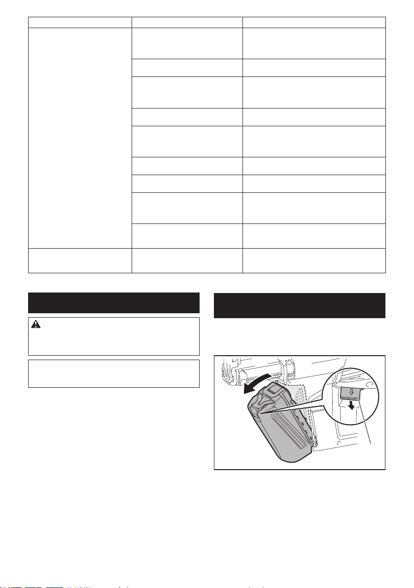
47 ESPAÑOL
Estado de la anomalía Causa probable (avería) Remedio
Laaspiradoranofuncionajuntocon
el interruptor de la herramienta.
Launidadinalámbricanoestáinstalada
en la herramienta.
Launidadinalámbricaestáinstalada
incorrectamente en la herramienta.
Instalelaunidadinalámbricacorrectamente.
Laterminaldelaunidadinalámbricay/o
laranuraestásucia.
Retire con cuidado el polvo y la suciedad en la
terminaldelaunidadinalámbricaylimpielaranura.
Elbotóndeactivacióninalámbricaenla
herramienta no se ha oprimido.
Oprimaelbotóndeactivacióninalámbricadurante
un lapso breve y asegúrese de que la luz indicadora
deactivacióninalámbricaestéparpadeandoen
azul.
El interruptor de modo en espera en la
aspiradoranoestáajustadoen“AUTO”.
Ajusteelinterruptordemodoenesperaenla
aspiradoraen“AUTO”.
Másde10herramientasestánregistra-
das en la aspiradora.
Vuelva a realizar el registro de la herramienta.
Simásde10herramientasestánregistradasenla
aspiradora, la herramienta registrada al principio se
cancelaráautomáticamente.
Laaspiradoraborrótodoslosregistros
de la herramienta.
Vuelva a realizar el registro de la herramienta.
Nohaysuministrodeenergía. Suministreenergíaalaherramientayala
aspiradora.
Laherramientaylaaspiradoraestán
lejosunadelaotra(fueradelrangode
transmisión).
Acerquemáslaherramientaalaaspiradora.La
distanciamáximadetransmisiónesdeaproxima-
damente10m,peropuedevariarenfuncióndelas
circunstancias.
Laperturbaciónradioeléctricagenerada
por otros aparatos que emiten ondas de
radio de alta intensidad.
Mantengalaherramientaylaaspiradoralejosde
aparatos tales como dispositivos Wi-Fi y hornos de
microondas.
La aspiradora funciona aun cuando
el gatillo interruptor de la herra-
mientanohasidojalado.
Otrosusuariosestánusandolaactiva-
cióninalámbricadelaaspiradoracon
sus herramientas.
Apagueelbotóndeactivacióninalámbricadelas
demásherramientasocanceleelregistrodedichas
herramientas.
MANTENIMIENTO
PRECAUCIÓN: Asegúrese siempre de que la
herramienta esté apagada y el cartucho de batería
extraído antes de intentar realizar una inspección
o mantenimiento.
AVISO: Nunca use gasolina, bencina, diluyente
(tíner), alcohol o sustancias similares. Puede que
esto ocasione grietas o descoloramiento.
ParamantenerlaSEGURIDADyFIABILIDADdelpro-
ducto, las reparaciones, y cualquier otra tarea de man-
tenimientooajustedeberánserrealizadasencentros
deservicioautorizadosodefábricaMakita,empleando
siempre repuestos Makita.
Reemplazo del ltro de la caja para
polvo
Accesorio opcional
1. Extraigalacajaparapolvomientraspresiona
haciaabajolapalancadelacajaparapolvo.
1
►1. Palanca
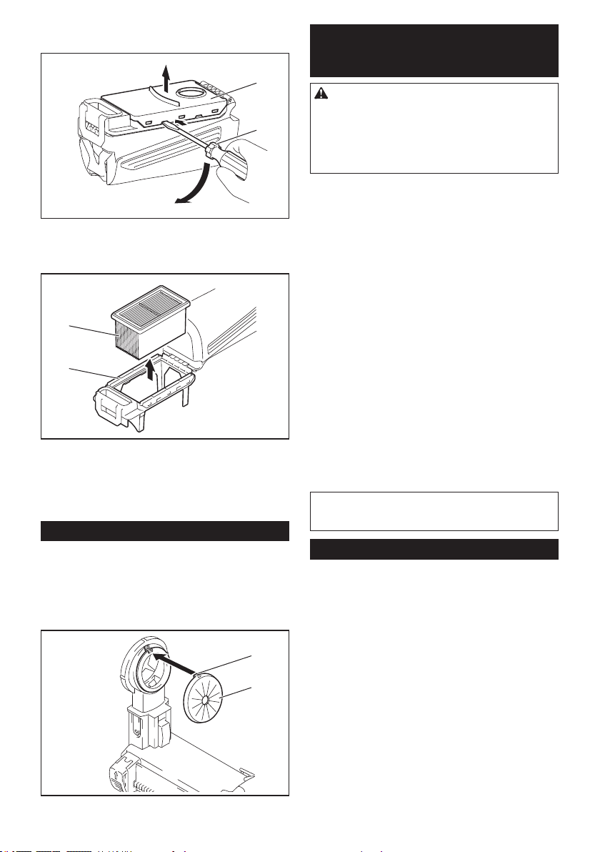
48 ESPAÑOL
2.
Inserte un destornillador de punta plana en las ranu-
rasdelacubiertadelltroparaextraerlacubiertadelltro.
2
1
►1. Destornillador de punta plana 2. Cubierta del
ltro
3. Extraigaelltrodelacajadelltro.
1
2
►1. Filtro 2.Cajadelltro
4. Coloqueunltronuevoenlacajadelltroyluego
jelacubiertadelltro.
5. Cierrelacubiertadelacajaparapolvoyluego
fíjelaenelsistemaderecoleccióndepolvo.
Reemplazo del tapón sellador
Accesorio opcional
Sieltapónselladorestádesgastado,eldesempeñode
larecoleccióndepolvoseveráreducido.Reemplácelo
si presenta indicios de desgaste.
Retireeltapónselladoryluegocoloqueunonuevocon
su protuberancia orientada hacia arriba.
1
2
►1. Protuberancia 2.Tapónsellador
ACCESORIOS
OPCIONALES
PRECAUCIÓN: Estos accesorios o aditamen-
tos están recomendados para utilizarse con su
herramienta Makita especicada en este manual.
El empleo de cualquier otro accesorio o aditamento
puede conllevar el riesgo de lesiones personales.
Utilice los accesorios o aditamentos solamente para
sunestablecido.
Sinecesitacualquierayudaparamásdetallesen
relaciónconestosaccesorios,pregunteasucentrode
servicio local Makita.
• Brocasconpuntasdecarburo(puntasdecarburo
SDS-Plus)
• Puntadecorona
• Cinceldepunta
• Puntadecoronadediamante
• Cincelplano
• Cinceldedesincrustación
• Cincelderanurado
• Adaptadordemandril
• Portabrocasadaptadorsinllave
• Grasaparapuntas
• Calibradordeprofundidad
• Soplador
• Contenedordepolvo
• Juegocontenedordepolvo
• Sistemaderecoleccióndepolvo
• Unidadinalámbrica
• BateríaycargadororiginalesdeMakita
• Gafasdeseguridad
• Maletíndetransportedeplástico
NOTA:Algunosdelosartículosenlalistapueden
incluirse en el paquete de la herramienta como acce-
soriosestándar.Éstospuedenvariardepaísapaís.
GARANTÍA LIMITADA DE MAKITA
Ésta Garantía no aplica para México
Consultelahojadelagarantíaanexaparaverlos
términosmásvigentesdelagarantíaaplicableaeste
producto.Encasodenodisponerdeestahojade
garantíaanexa,consultelosdetallessobrelagarantía
descritosenelsitiowebdesupaísrespectivoindicado
acontinuación.
EstadosUnidosdeAmérica:www.makitatools.com
Canadá:www.makita.ca
Otrospaíses:www.makita.com

49

50

51

Some dust created by power sanding, sawing, grinding, drilling, and other
construction activities contains chemicals known to the State of California
to cause cancer, birth defects or other reproductive harm. Some examples
of these chemicals are:
• lead from lead-based paints,
• crystalline silica from bricks and cement and other masonry products, and
• arsenic and chromium from chemically-treated lumber.
Your risk from these exposures varies, depending on how often you do this
type of work. To reduce your exposure to these chemicals: work in a well
ventilated area, and work with approved safety equipment, such as those
dust masks that are specially designed to filter out microscopic particles.
WARNING
< USA only >
ADVERTENCIA
Algunos polvos creados por el lijado, aserrado, esmerilado, taladrado y
otras actividades de la construcción contienen sustancias químicas
reconocidas por el Estado de California como causantes de cáncer, defectos
de nacimiento y otros peligros de reproducción. Algunos ejemplos de estos
productos químicos son:
• plomo de pinturas a base de plomo,
• sílice cristalino de ladrillos y cemento y otros productos de albañilería, y
• arsénico y cromo de maderas tratadas químicamente.
El riesgo al que se expone varía, dependiendo de la frecuencia con la que
realice este tipo de trabajo. Para reducir la exposición a estos productos
químicos: trabaje en un área bien ventilada y póngase el equipo de seguridad
indicado, tal como las máscaras contra polvo que están especialmente
diseñadas para filtrar partículas microscópicas.
< Sólo en los Estados Unidos >
Makita Corporation
3-11-8, Sumiyoshi-cho,
Anjo, Aichi 446-8502 Japan
www.makita.com
885632A949
XRH08-1
EN,ESMX
20180208