Loading ...
Loading ...
Loading ...
Troubleshooting
Ou
●
tdoor Board Diagram
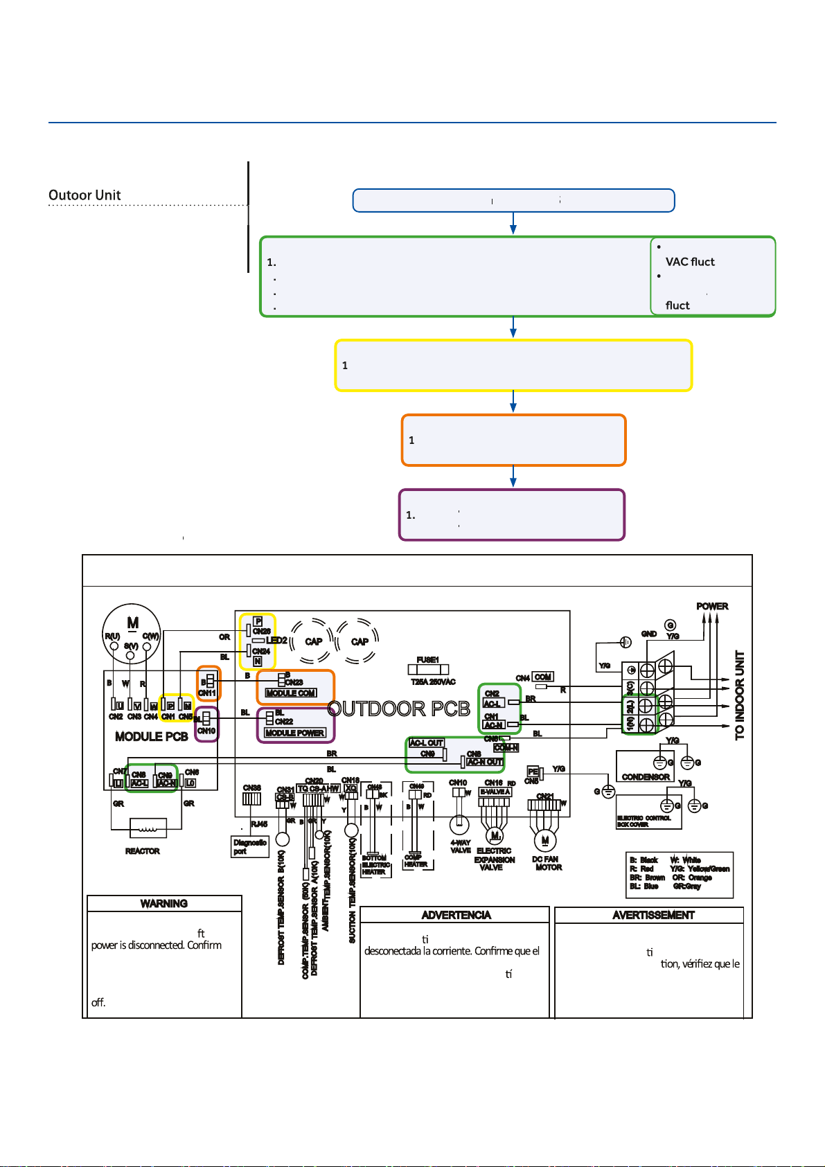
OUTDOOR UNIT WIRING DIAGRAM
COMPRESSOR
Electrical Shock Haza
●
rd
Capacitor retains charge a
e
●
r
voltage at capacitor has diss
●
ipated
(<10V DC) with hand held voltmeter
before servicing. LED2 light
between CN24 and CN26 should be
Riesgo de Descarga Eléctrica
El capacitor re
ene carga una vez
voltaje del capacitor se haya disipado (<10V
DC) apoyando la mano sobre el vol
metro
antes de realizar el servicio técnico. La luz
LED2 que se encuentra entre CN24 y CN26
deberá estar apagada.
Risque de choc électrique
Le condensateur conserve sa charge après la
coupure de l’alimenta
on électrique. Avant
de procéder à une répara
courant au condensateur s’est dissipé
(<10 VCC) à l’aide d’un voltmètre manuel. Le
voyant LED2 entre CN24 et CN26 doit être
éteint.
0011509127
Check This First
Models:
1U09EH2VHE
1U12EH2VHE
1U18EH2VHE
Line
v
oltage
a
v
ailable at:
1
.
TERMINAL
S
TRIP - 1(N) & 2 (L)
2
.
A
C
-L &
A
C
-N at the PCB - CN2 & CN1
3
.
A
C
-L OUT &
A
C
-N OUT at the PCB - CN8 & CN9
4
.
A
C
-L &
A
C
-N at the I
P
M -CN8 & CN9 (9K) / CN1 & CN2 (12K/18K)
310+ VDC
a
v
ailable at:
1
.
P & N at the I
P
M - CN1 & CN5 (9K) / CN8 & CN9 (12K/18K)
2
.
P & N at the PCB - CN24 & CN26
Module
C
OM 5-G-15 VDC
a
v
ailable at:
1
.
CN23 at the PCB
2
.
CN11 at the I
P
M
Module p
o
w
er 5-G-15 VDC
a
v
ailable at:
1
.
CN22
A
T THE PCB
A
A
2
.
CN10
A
T THE I
A
A
P
M
1 (N) and 3 (C): 0-80
uating
2 (L) and 3 (C):
0-140
V
A
V
V
C
uating
Wiring Diag
r
am
R
e
f
e
f
f
r
en
c
e
Conditions Needed for Basic Operation
3-minu
t
es of
time
del
a
y
f
r
f
f
om
the
call
f
or heating
f
f
or
c
ooling
ERROR CODES and Troubleshooting
PAGE 76
Loading ...
Loading ...
Loading ...