Loading ...
Loading ...
Loading ...
PAGE: 5 / 10
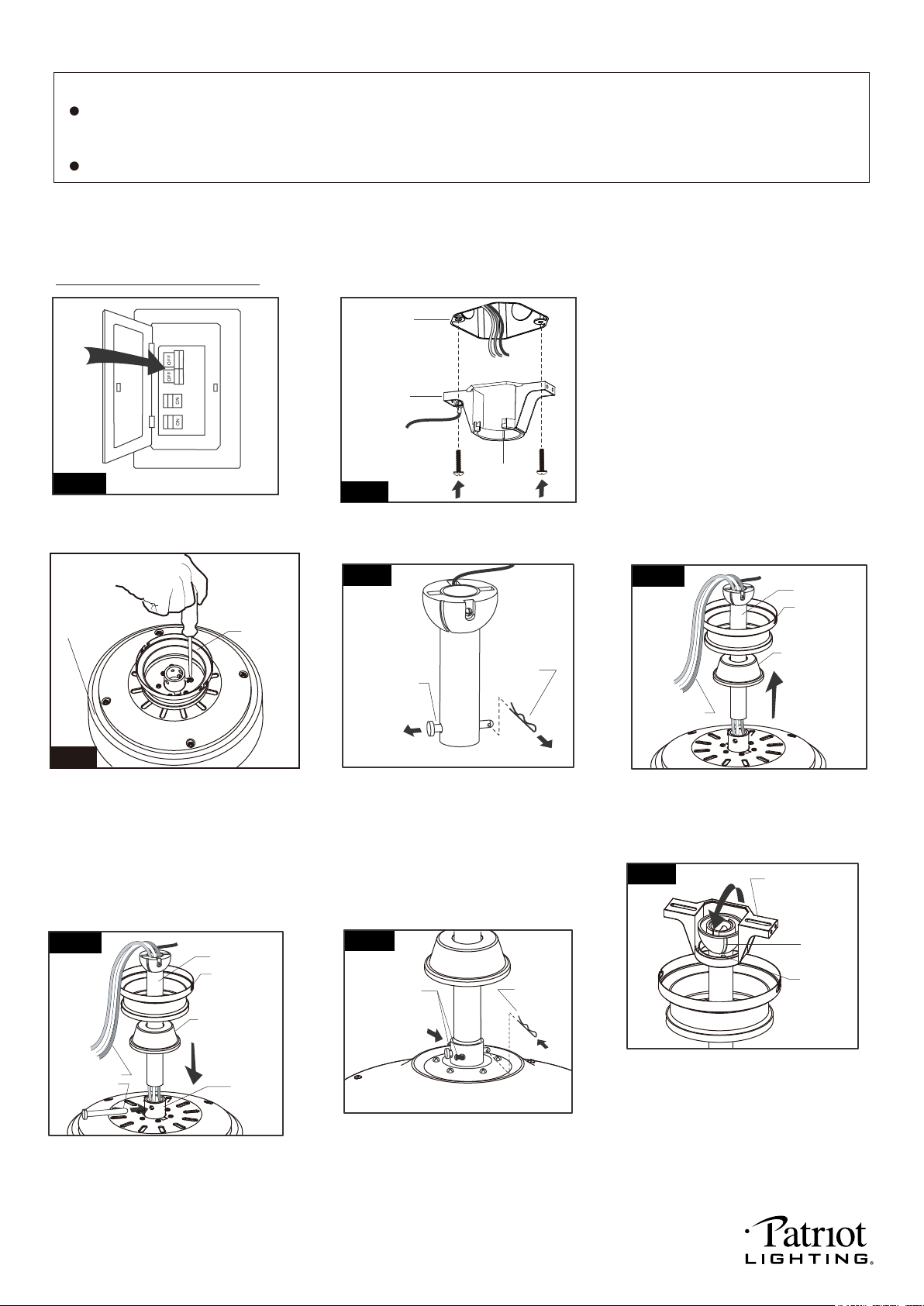
(For downrod mount only):
Thread the motor wires through the
downrod stand cover, canopy and
downrod.
Installation Steps :
Hanger Pin
Lock Pin
INSTALLATION INSTRUCTIONS
IMPORTANT:
NOTE: The fan weight is 21.1 lbs (9.57 kgs). Be sure the outlet box you are using is securely attached to the building
structure and can support the full weight of the fan. Failing to do so can result in serious injury.
Tighten the hanger bracket to the outlet
box with two mounting screws. (To reduce
the risk of fire, electric shock, or personal
injury, mount to an outlet box marked
"Acceptable for fan support" and use
mounting screws provided with the outlet
box.)
Note: For sloped ceiling installation, make
sure that the chip of the hanger bracket
is toward the floor.
(
For downrod mount only):
Hang the fan on hanger bracket,
and make sure the slot of hanger
ball is snapped into the chip of
hanger bracket exactly.
Note: For sloped ceiling installation,
make sure the slot of hanger ball
and the chip of hanger bracket
face down.
Fig.1
Turn OFF the electric circuit at the
main fuse or circuit breaker box.
(
For downrod mount only):
Remove the lock pin and take off
the hanger pin.
Fig.4
(
For downrod mount only):
Tighten the two collar screws.
Slide lock pin into hanger
pin until it is locked into position.
(
For downrod mount only):
Loosen the collar screws out part way.
Insert the downrod into the collar.
Slide hanger pin through holes of
collar and downrod.
(
For ceiling mount only):
Remove the canopy cover from the
canopy.
Remove three of six screws (every
other one screw) securing the motor
collar to the top of the fan motor housing.
Attach the canopy to the housing
with three screws.
Go to Fig.9 for the next step.
Fig.3
Housing
Canopy
Downrod
Canopy
Motor Wires
Downrod Stand
Cover
Fig.5
Fig.7
Lock Pin
Collar Screws
Hanger Pin
Downrod
Canopy
Motor Wires
Downrod Stand
Cover
Fig.6
Slot
Chip
Hanger Bracket
Fig.8
BEFORE YOU BEGIN INSTALLATION, CAREFULLY READ ALL INFORMATION PROVIDED IN THE SAFETY
INSTRUCTIONS AND INSTALLATION INSTRUCTIONS. IF IN DOUBT, CONSULT A QUALIFIED
ELECTRICIAN.
SAVE ALL INSTRUCTIONS.
Hanger
Bracket
Fig.2
Outlet Box
Chip
Collar
220104
Loading ...
Loading ...
Loading ...