
OWNER'S MANUAL
CAUTION
RISKOFELECTRICSHOCK
DO NOTOPEN
CAUTION: TO REDUCE THE RISK OF
ELECTRIC SHOCK, DO NOT REMOVE
COVER (OR BACK). NO USER-SERVICEABLE
PARTS INSIDE. REFER SERVICING TO
QUALIFIED SERVICE PERSONNEL.
• Explanation of Graphical Symbols
The lightning flash with arrowhead symbol, within an
equilateral triangle, is intended to alert you to the
presence of uninsulated "dangerous voltage" within
the product's enclosure that may be of sufficient
magnitude to constitute a risk of electric shock to
persons.
The exclamation point within an equilateral triangle
is intended to alert you to the presence of important
operating and maintenance (servicing) instructions in
the literature accompanying the appliance.
1 Read [nstructions - All the safety and operating instructions
should be read before the product is operated.
2 Retain Instructions - The safety and operating instructions
should be retained for future reference.
3 Heed Warnings - All warnings on the product and in the
operating instructions should be adhered to.
4 Follow Instructions - All operating and use instructions
should be followed.
5 Cleaning - Unplug this product from the wall outlet before
cleaning. Do not use liquid cleaners or aerosol cleaners.
6 Attachments - Do not use attachments not recommended by
the product manufacturer as they may cause hazards.
7 Water and Moisture - Do not use this product near water -
for example, near a bath tub, wash bowl, kitchen sink, or
laundry tub; in a wet basement; or near a swimming pool;
and the like.
8 Accessories - Do not place this product on an unstable cart,
stand, tripod, bracket, or table. The product may fall,
causing serious injury to a child or adult, and serious
damage to the product. Use only with a cart, stand, tripod,
bracket, or table recommended by the manufacturer, or sold
with the product. Any mounting of the product should
follow the manufacturer's instructions, and should use a
mounting accessory recommended by the manufacturer.
9 A product and cart combination should be moved with care.
Quick stops, excessive force, and uneven surfaces may
cause the product and cart combination to
overturn.
10 Ventilation - Slots and openings in the cabinet are provided
for ventilation and to ensure reliable operation of the
product and to protect it from overheating, and these
openings must not be blocked or covered. The openings
should never be blocked by placing the product on a bed,
sofa, rug, or other similar surface. This product should not
be placed in a built-in installation such as a bookcase or rack
unless proper ventilation is provided or the manufacturer's
instructions have been adhered to.
11 Power Sources - This product should be operated only from
the type of power source indicated on the marking label. If
you are not sure of the type of power supply to your home,
consult your product dealer or local power company. For
products intended to operate from battery power, or other
sources, refer to the operating instructions.
12 Grounding or Polarization - This product may be equipped
with a polarized alternating current line plug (a plug having
one blade wider than the other). This plug will fit into the
power outlet only one way. This is a safety feature. If you
are unable to insert the plug fully into the outlet, try
reversing the plug. If the plug should still fail to fit, contact
your electrician to replace your obsolete outlet. Do not
defeat the safety purpose of the polarized plug.
13 Power-Cord Protection - Power-supply cords should be
routed so that they are not likely to be walked on or pinched
by items placed upon or against them, paying particular
attention to cords at plugs, convenience receptacles, and the
point where they exit from the product.
14 Lightning - For added protection for this product during a
lightning storm, or when it is left unattended and unused for
long periods of time, unplug it from the wall outlet and
disconnect the antenna or cable system. This will prevent
damage to the product due to lightning and power-line
surges.
15 Power Lines - An outside antenna system should not be
located in the vicinity of overhead power lines or other
electric light or power circuits, or where it can fall into such
power lines or circuits. When installing an outside antenna
system, extreme care should be taken to keep from touching
such power lines or circuits as contact with them might be
fatal.
16 Overloading - Do not overload wall outlets, extension
cords, or integral convenience receptacles as this can result
in a risk of fire or electric shock.
17 Object and Liquid Entry - Never push objects of any kind
into this product through openings as they may touch
dangerous voltage points or short-out parts that could result
in a fire or electric shock. Never spill liquid of any kind on
the product.
18 Servicing - Do not attempt to service this product yourself
as opening or removing covers may expose you to
dangerous voltage or other hazards. Refer all servicing to
qualified service personnel.
19 Damage Requiring Service - Unplug this product from the
wall outlet and refer servicing to qualified service personnel
under the following conditions:
a) When the power-supply cord or plug is damaged,
b) If liquid has been spilled, or objects have fallen into the
product,
c) If the product has been exposed to rain or water,
Caution-i En
d) ff the product does not operate normally by following
the operating instructions. Adjust only those controls
that are covered by the operating instructions as all
irnproper adjustrnent of other controls rnay result ill
darnage and will often require extensive work by a
qualified technician to restore the product to its norrnal
operation,
e) ff the product has been dropped or darnaged in any
way, and
f) When the product exhibits a distinct change in perfor-
mance - this indicates a need for service.
20 Replacement Parts - When replacement parts are required,
be sure the service technician has used replacement parts
specified by the manufacturer or have the same
characteristics as the original part. Unauthorized
substitutions may result in fire, electric shock, or other
hazards.
2"1 Safety Check- Upon completion of any service or repairs to
this product, ask the service technician to perform safety
checks to determine that the product ix in proper operating
condition.
22 Wall or Ceiling Mounting - The unit should be mounted
to a wall or ceiling only as recommended by the
manufacturer.
23 Heat - The product should be situated away from heat
sources such as radiators, heat registers, stoves, or other
products (including amplifiers) that produce heat.
Note to CATV system installer:
This reminder is provided to call the CATV system installer's
attention to Article 820-40 of the NEC that provides
guidelines for proper grounding and, in particular, specifies
that the cable ground shall be connected to the grounding
system of the building, as close to the point of cable entry as
practical.
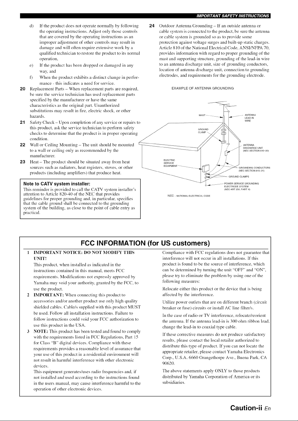
24
li_l'.Iol;_lCzfivEig.,.",lzf.,_=llJ'Jh%."tl[;llI_lffo]iv_
Outdoor Antenna Grounding - ff an outside antenna or
cable system is connected to the product, be sure the antenna
or cable system is grounded so as to provide some
protection against voltage surges and built-up static charges.
Article 810 of the National Electrical Code, ANSI/NFPA 70,
provides information with regard to proper grounding of the
mast and supporting structure, grounding of the lead-in wire
to an antenna discharge unit, size of grounding conductors,
location of antenna discharge unit, connection to grounding
electrodes, and requirements for the grounding electrode.
EXAMPLE OF ANTENNA GROUNDING
LEAD IN
WIRE
ELECTRIC
SERVICE
ANTENNA
D_SCHARGE UNiT
(NEC SECTION 810,20)
(NEC SECTION 810,21)
NEC NATIONAL ELECTRICAL CODE
ELECTRODE SYSTEM
(NEC ART 250. PART H)
FCC INFORMATION (for US customers)
1 IMPORTANT NOTICE: DO NOT MODIFY THIS
UNIT!
This product, when installed as indicated in the
instructions contained in this manual, meets FCC
requirements. Modifications not expressly approved by
Ymnaha may void your authority, granted by the FCC, to
use the product.
IMPORTANT: When connecting this product to
accessories and/or another product use only high quality
shielded cables. Cable/s supplied with this product MUST
be used. Follow all installation instructions. Failure to
follow instructions could void your FCC authorization to
use this product in the USA.
NOTE: This product has been tested and found to comply
with the requirements listed in FCC Regulations, Part 15
for Class "B" digital devices. Compliance with these
requirements provides a reasonable level of assurance that
your use of this product in a residential environment will
not result in harmful interference with other electronic
devices.
This equipment generates/uses radio frequencies and, if
not installed and used according to the instructions found
in the users manual, may cause interference harmful to the
operation of other electronic devices.
Compliance with FCC regulations does not guarantee that
interference will not occur in all installations. If this
product is found to be the source of interference, which
can be determined by turning the unit "OFF" and "ON",
please try to eliminate the problem by using one of the
following measures:
Relocate either this product or the device that is being
affected by the interference.
Utilize power outlets that are on different branch (circuit
breaker or iklse) circuits or install AC line filteffs.
[n the case of radio or TV interference, relocate/reorient
the antenna. If the antenna lead-in is 300 ohm ribbon lead,
change the lead-in to coaxial type cable.
If these corrective measures do not produce satisfactory
results, please contact the local retailer authorized to
distribute this type of product. If you can not locate the
appropriate retailer, please contact Yamaha Electronics
Corp., U.S.A. 6660 Orangethorpe Ave., Buena Park, CA
90620.
The above statements apply ONLY to those products
distributed by Yamaha Corporation of America or its
subsidiaries.
Caution-ii En
1 To assure the finest performance, please read this manual
carefully, Keep it in a safe place for future reference,
2 Install this sound system in a well ventilated, cool, dry, clean
place - away fi'orn direct sunlight, heat sources, vibration,
dust, moisture, and/or cold, Allow ventilation space of at least
30 crn on the top, 20 crn on the left and right, and 20 crn on
the back of this unit,
3 Locate this unit away fi'om other electrical appliances, motors,
or transformers to avoid humming sounds.
4 Do not expose this unit to sudden temperature changes from
cold to hot, and do not locate this unit in a environment with
high humidity (i.e. a room with a humidifier) to prevent
condensation inside this unit, which may cause an electrical
shock, fire, damage to this unit, and/or personal injury.
5 Avoid installing this unit where foreign object may fall onto
this unit and/or this unit may be exposed to liquid dripping or
splashing. On the top of this unit, do not place:
- other components, as they may cause damage and/or
discoloration on the surface of this unit.
- burning objects (i.e. candles), as they may cause fire,
damage to this unit, and/or personal injury.
- containers with liquid in them, as they may fall and liquid
may cause electrical shock to the user and/or damage to
this unit.
6 Do not cover this unit with a newspaper, tablecloth, curtain,
etc. in order not to obstruct heat radiation. If the temperature
inside this unit rises, it may cause fire, damage to this unit,
and/or personal injury.
7 Do not plug in this unit to a wall outlet until all connections
are complete.
8 Do not operate this unit upside-down. It may overheat,
possibly causing damage.
9 Do not use force on switches, knobs and/or cords.
.10 When disconnecting the power cable from the wall outlet,
grasp the plug; do not pull the cord.
.1.1 Do not clean this unit with chemical solvents; this might
damage the finish. Use a clean, dry cloth.
"12 Only voltage specified on this unit must be used. Using this
unit with a higher voltage than specified is dangerous and may
cause fire, damage to this unit, and/or personal injury. Yamaha
will not be held responsible for any damage resulting from use
of this unit with a voltage other than specified.
"1:3 To prevent damage by lightning, keep the power cord and
outdoor antennas disconnected from a wall outlet or the unit
during a lightning storm.
"14 Do not attempt to modify or fix this unit. Contact qualified
Yamaha service personnel when any service is needed. The
cabinet should never be opened for any reasons.
"15 When not planning to use this unit for long periods of time
(i.e. vacation), disconnect the AC power plug from the wall
outlet.
"16 [nstall this unit near the AC outlet and where the AC power
plug can be reached easily.
"17 Be sure to read the "Troubleshooting" section on common
operating errors before concluding that this unit is faulty.
"18 Before moving this unit, press @STANDBY/ON to set this
unit in the standby mode, and disconnect the AC power plug
from the wall outlet.
"19 VOLTAGE SELECTOR (Asia and General models only)
The VOLTAGE SELECTOR on the rear panel of this unit
must be set for your local main voltage BEFORE plugging
into the AC wall outlet.
Voltages are 110-120/220-240 V AC, 50/60 Hz.
20 The batteries shall not be exposed to excessive heat such as
sunshine, fire or like.
2"1 Excessive sound pressure from earphones and headphones can
cause hearing loss.
WARNING
TO REDUCE THE RISK OF FIRE OR ELECTRIC
SHOCK, DO NOT EXPOSE THIS UNIT TO RAIN
OR MOISTURE.
This unit is not disconnected from the AC power
source as long as it is connected to the wall outlet, even
if this unit itself is turned off by @STANDRY/ON
This state is called the standby mode. In this state, this
unit is designed to consume a very small quantity of
power.
FOR CANADIAN CUSTOMERS
To prevent electric shock, match wide blade of plug to
wide slot and fully insert.
This Class B digital apparatus complies with Canadian
ICES-003.
POUR LES CONSOMMATEURS CANADIENS
Pour &iter les chocs dlectriques, introduire la lame la
plus large de la fiche dans la borne correspondante de
la prise et pousser jusqu'au fond.
Cet appareil num&ique de la classe B est conforme
la norme NMB-003 du Canada.
IMPORTANT
Please record the serial number of this unit in the space
below.
MODEL:
Serial No.:
The serial number is located on the rear of the unit.
Retain this Owner's Manual in a safe place for future
reference.
Caution-iii En
Features ................................................................... 2
Getting started ........................................................ 3
Quick start guide .................................................... 4
Preparation: Check the items ..................................... 4
Step 1: Set up your speakers ...................................... 5
Step 2: Connect your DVD player and other
components ............................................................ 6
Step 3: Press SCENE 1 button ................................... 7
What do you want to do with this unit? ..................... 8
Connections ............................................................. 9
Rear panel .................................................................. 9
Placing speakers ....................................................... 10
Connecting speakers ................................................ 11
Information on jacks and cable plugs ...................... 13
Information on HDM[ TM .......................................... 14
Audio and video signal flow .................................... 14
Connecting video components ................................. 15
Connecting other components ................................. 16
Connecting audio components ................................. 18
Connecting a Yamaha iPod TM universal dock or
Bluetooth TM adapter ............................................. 19
Using the VIDEO AUX jacks on the fi'ont panel .... 19
Connecting the FM and AM antennas ..................... 20
Connecting the power cable ..................................... 20
Setting the speaker impedance ................................. 21
Turning on and off the power .................................. 21
Front panel display .................................................. 22
Optimizing the speaker setting
for your listening room .................................... 24
Using AUTO SETUP .............................................. 24
Selecting the SCENE templates ........................... 28
Selecting the desired SCENE template .................... 28
Creating your original SCENE templates ................ 31
Using remote control on the SCENE feature ........... 32
Playback ................................................................ 33
Basic operations ....................................................... 33
Selecting audio input jacks
(AUDIO SELECT) .............................................. 34
Selecting the MULTI CH INPUT component ......... 34
Displaying the current status of this unit on a video
monitor ................................................................ 35
Using your headphones ............................................ 35
Muting the audio output ........................................... 35
Playing video sources in the background of an audio
source ................................................................... 36
Displaying the input source information ................. 36
Using the sleep timer ............................................... 37
Sound field programs ........................................... 38
Sound field program descriptions ............................ 38
Using audio features ............................................. 41
Enjoying high quality sound .................................... 41
Adjusting the tonal quality ....................................... 41
Adjusting the speaker level ...................................... 41
Selecting the night listening mode ........................... 42
FM/AM tuning ...................................................... 43
Automatic tuning ..................................................... 43
Manual tuning .......................................................... 43
Automatic preset tuning ........................................... 44
Manual preset tuning ............................................... 44
Selecting preset stations ........................................... 45
Exchanging preset station ........................................ 45
XM Satellite Radio tning ...................................... 46
Connecting the XM Mini-Tuner Dock .................... 46
Activating XM Satellite Radio ................................ 47
Basic XM Satellite Radio operations ....................... 47
Setting XM Satellite Radio preset channels ............ 49
Displaying the XM Satellite Radio information ...... 50
SIRIUS Satellite Radio TM tuning ......................... 51
Connecting the SiriusConnect TM tuner .................... 51
Activating SIRIUS Satellite Radio TM subscription.. 52
Basic SIRIUS Satellite Radio TM operations ............ 52
Setting the SIRIUS Satellite Radio TM preset
channels ............................................................... 54
Setting the Parental Lock ......................................... 54
Displaying the SIRIUS Satellite Radio TM
information .......................................................... 56
Using iPod TM .......................................................... 57
Controlling iPod TM ................................................... 57
Using Bluetooth TM components ............................ 59
Pairing the Bluetooth TM adapter and your Bluetooth
component ........................................................... 59
Playback of the Bluetooth TM component ................. 59
Recording ............................................................... 6l!
SET MENU ............................................................ 61
Using SET MENU ................................................... 62
1 SOUND MENU .................................................... 63
2 INPUT MENU ...................................................... 68
3 OPTION MENU ................................................... 70
Remote control features ........................................ 73
Controlling this unit, a TV, or other components .... 73
Setting remote control codes ................................... 75
Advanced setup ...................................................... 76
_L__ _ Og, L_ • _ ._
Troubleshooting ..................................................... 78
Glossary .................................................................. 88
Specifications ......................................................... 911
Index ....................................................................... 91
(at the end of this manual)
Front panel ................................................................ i
Remote control ....................................................... ii
List of remote control codes ................................. iii
About this manual
• "4_"-indicates a tip lor your operation.
• Some operations can be performed by using either the buttons on the
fi'ont panel or the ones on the remote control. In case the button
names difli_r between the front panel and the remote control, the
button name on the remote control is given in parentheses.
• This manual is printed prior to production. Design and specifications
are subject to change in part as a result of improvements, etc. In case
of difli_rences between the manual and product, the product has
priority.
• "@SPEAKERS" or "@DVD" (example) indicates the name of the
parts on the front panel or the remote control. Relier to the attached
sheet or the pages at the end of this manual for the information about
each position of the parts.
• The symbol "_a " with page number(s) indicates the corresponding
refi_rence page(s).
R En
Built-in 5-channel power amplifier
• Minimum RMS output power
[U.S.A. and Canada models]
(1 kHz, 0.9% THD, 8 [2)
105 W/ch
[Other models]
(1 kHz, 0.9% THD, 6 [_)
105 W/ch
SCENE select function
• Preset SCENE templates for various situations
• SCENE template customizing capability
Decoders and DSP circuits
• Proprietary Yamaha technology for the creation of multi-
channel surround sound
• Compressed Music Enhancer )node
• Dolby Digital decoder
• Dolby Pro Logic/Dolby Pro Logic II decoder
• DTS decoder
• Neural Surround decoder
(U.S.A. and Canada models only)
• Virtual CINEMA DSP
• SILENT CINEMA _"
Radio tuners
• FM/AM tuning capability
• XM Satellite Radio tuning capability (using XM Mini-Tuner
and Home Dock, sold separately)
• SIRIUS Satellite Radio TM tuning capability (using SIRIUS
Connect tuner, sold separately)
HDMI (High-Definition Multimedia Interface)
• HDM[ interface for standard, enhanced or high-definition
video (includes 1080p video signal transmission) as well as
multi-channel digital audio
DOCK terminal
• DOCK terminal to connect a Yamaha iPod universal dock
(such as YDS-10, sold separately) or Bluetooth adapter
(such as YBA-10, sold separately).
Other features
• YPAO (Yamaha Parametric Room Acoustic Optimizer) for
automatic speaker setup
• 192-kHz/24-bit D/A converter
• DIRECT mode for high quality sound for all sources
• 6 additional input jacks for discrete multi-channel input
• OSD (on-screen display) menus that allow you to optimize
this unit to suit your individual audiovisual system
• Component video input/output capability
(3 COMPONENT VIDEO INs and 1 MONITOR OUT)
• Optical and coaxial digital audio signal jacks
• Sleep timer
• Cinema and music night listening )nodes
• iPod controlling capability
• Remote control with preset remote control codes
Drl
DIGITAL
Manufactured under license from Dolby Laboratories.
"Dolby", "Pro Logic", and the double-D symbol are trademarks
of Dolby Laboratories.
SILENT T_
CINEMA
"SILENT CINEMA" is a trademark of YAMAHA
CORPORATION.
iPod TM
"iPod" is a trademark of Apple, Inc., registered in the U.S. and
other countries.
Bluetooth TM
Bluetooth is a registered trademark of the Bluetooth SIG and is
used by Yamaha in accordance with a license agreement.
H m!
"HDM[", the "HDM[" logo and "High-Definition Multimedia
Interface" are trademarks or registered trademarks of HDM[
Licensing LLC.
Digffal Surm_nd
"DTS" and "DTS Digital Surround" are registered trademarks of
DTS, Inc.
XM£?Q XMMini.TunEr
The XM name and related logos are registered trademarks of XM
Satellite Radio Inc.
_neuralSURROUNO_
Neural Surround '_' name and related logos are trademarks owned
by Neural Audio Corporation.
©2006 SIRIUS Satellite Radio Inc. "SIRIUS", "Sirius Connect",
the SIRIUS dog logo, channel names and logos are trademarks of
SIRIUS Satellite Radio Inc.
2 En
• Supplied accessories
Check that you received all of the following parts.
Remote control
Batteries (2) (AAA, R03, UM-4)
Optimizer microphone
AM loop antenna
Indoor FM antenna
• VOLTAGE SELECTOR
(Asia and General models only)
Caution
The VOLTAGE SELECTOR on the rear panel of this
unit must be set for your local voltage BEFORE
plugging the power cable into the AC wall outlet.
Improper setting of the VOLTAGE SELECTOR may
cause damage to this unit and create a potential fire
hazard.
Rotate the VOLTAGE SELECTOR clockwise or
counterclockwise to the correct position using a
straight slot screwdriver.
Voltages are as follows:
Asia model ................... 2201230-240 V AC, 50160 Hz
General model
...................... 110/l 2012201230-240 V AC, 50160 Hz
VOLTAGE
SELECTOR
......... Voltage indication
We Want You Listening For A Lifetime
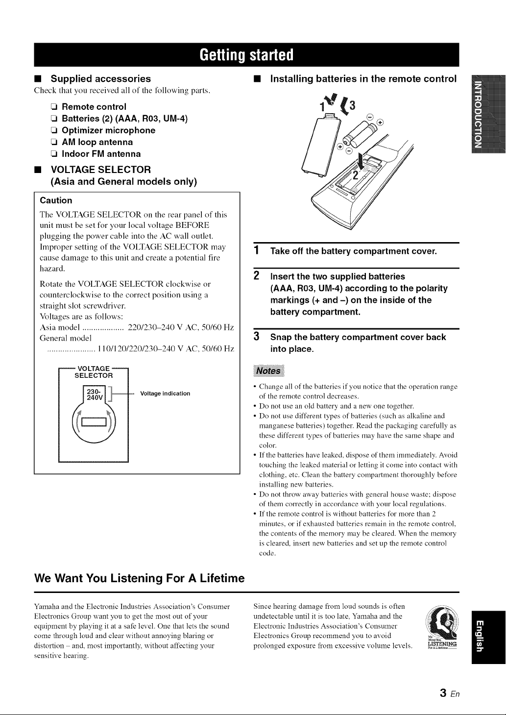
Installing batteries in the remote control
'3
1 Take off the battery compartment cover.
2 Insert the two supplied batteries
(AAA, R03, UM-4) according to the polarity
markings (+ and -) on the inside of the
battery compartment.
3
Snap the battery compartment cover back
into place.
• Change all of the batteries if you notice that the operation range
of the remote control decreases.
• Do not use all old battery and a new one together.
• Do not use different types of batteries (such as alkaline and
manganese batteries) together. Read the packaging carefully as
these different types of batteries )nay have the same shape and
color.
• If the batteries have leaked, dispose of them immediately. Avoid
touching the leaked material or letting it come into contact with
clothing, etc. Clean the battery compartment thoroughly before
installing new batteries.
• Do not throw away batteries with general house waste; dispose
of them correctly in accordance with your local regulations.
• If the remote control is without batteries for more than 2
minutes, or if exhausted batteries remain in the remote control,
the contents of the memory )nay be cleared. When the memory
is cleared, insert new batteries and set up the remote control
code.
Yamaha and the Electronic Industries Association's Consumer
Electronics Group want you to get the most out of your
equipment by playing it at a safe level. One that lets the sound
come through loud and clear without annoying blaring or
distortion and, most importantly, without affecting your
sensitive hearing.
Since hearing damage from loud sounds is often
undetectable until it is too late, Yamaha and the
Electronic Industries Association's Consumer
Electronics Group recommend you to avoid
prolonged exposure from excessive volume levels.
i'._ i
L!STENING
3 En
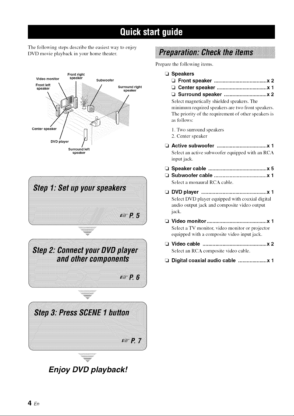
The following steps describe the easiest way to enjoy
DVD movie playback in your home theater.
Front right
Video monitor speaker Subwoofer
Front left
speaker Surround right
speaker
Center speaker
DVD player
Surround left
speaker
Prepare the following items.
Speakers
Front speaker ..................................... x 2
Center speaker ................................... x 1
Surround speaker .............................. x 2
Select magnetically shielded speakers. The
minimum required speakers are two front speakers.
The priority of the requirement of other speakers is
as follows:
1. Two surround speakers
2. Center speaker
Active subwoofer ................................... x 1
Select an active subwoofer equipped with an RCA
input jack.
Speaker cable ......................................... x 5
Subwoofer cable ..................................... x 1
Select a monaural RCA cable.
DVD player .............................................. x 1
Select DVD player equipped with coaxial digital
audio output jack and composite video output
jack.
Video monitor .......................................... x 1
Select a TV monitor, video monitor or projector
equipped with a composite video input jack.
Video cable ............................................. x 2
Select an RCA composite video cable.
Digital coaxial audio cable .................... x 1
Enjoy DVD playback!
4 En
Place your speakers in the room and connect them to this
unit.
Place your speakers and subwoofer in the
room.
2 Connect speaker cables to each speaker.
3
f
Cables are colored or shaped differently, perhaps with
a stripe, groove or ridge. Connect the striped
(grooved, etc.) cable to the '%" (red) terminals of
your speaker. Connect the plain cable to the "-"
(black) terminals.
Connect each speaker cable to the
corresponding speaker terminal of this unit.
_1_ _2 _3_ _4
Make sure that this unit and the subwoofer are
unplugged from the AC wall outlets.
@ Twist the exposed wires of the speaker cables
together to prevent short circuits.
@ Do not let the bare speaker wires touch each other.
@ Do not let the bare speaker wires touch any metal
part of this unit.
4
i
,rr/R,'lRgril.,,,g;r-
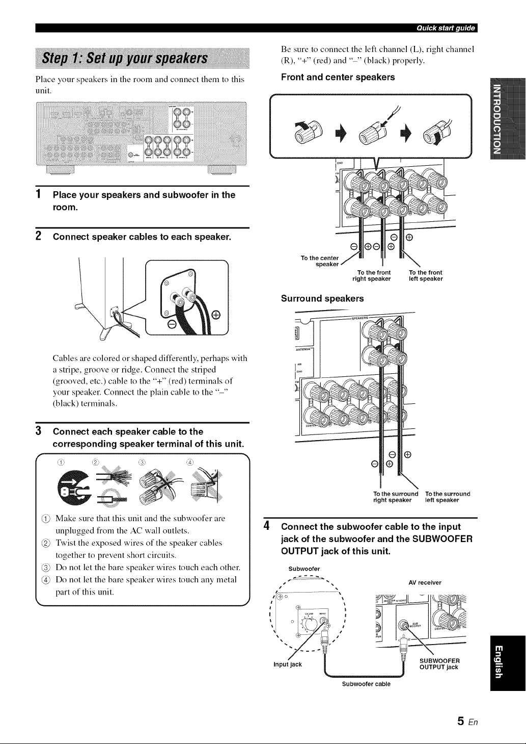
Be sure to connect the left channel (L), right channel
(R), '%" (red) and "-" (black) properly.
Front and center speakers
f
To th epent
To the front To the front
right speaker left speaker
1
Surround speakers
÷rg
To the surround To the surround
right speaker left speaker
Connect the subwoofer cable to the input
jack of the subwoofer and the SUBWOOFER
OUTPUT jack of this unit.
Subwoofer
s
s
AV receiver
SUBWOOFER
OUTPUT jack
Subwoofer cable
SEn
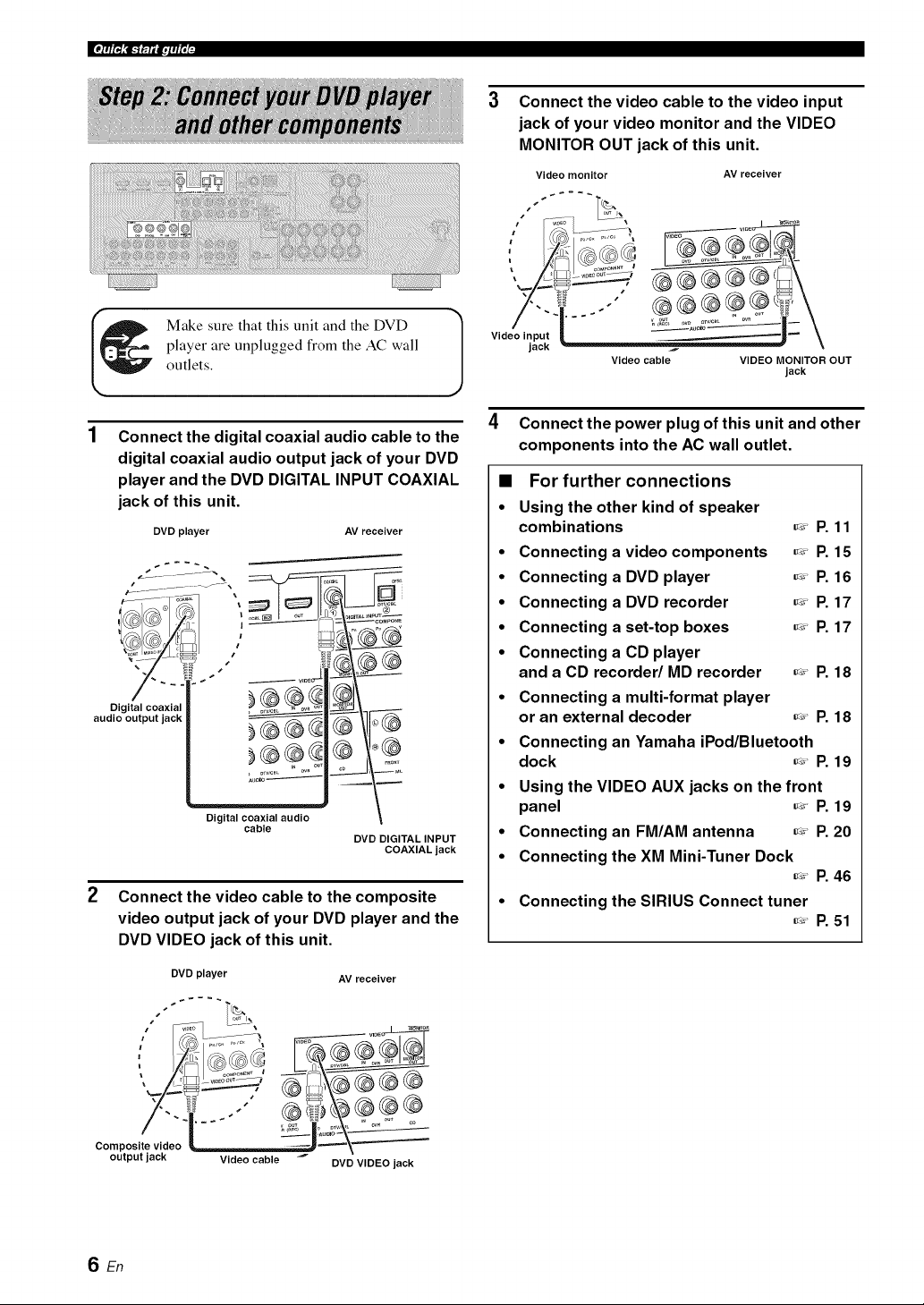
Connect the video cable to the video input
jack of your video monitor and the VIDEO
MONITOR OUT jack of this unit.
Video monitor
S
AV receiver
Make sure that this unit and the DVD
player are unplugged from the AC wall
outlets.
Connect the digital coaxial audio cable to the
digital coaxial audio output jack of your DVD
player and the DVD DIGITAL INPUT COAXIAL
jack of this unit.
DVD player AV receiver
....... ,
audio output jack | _ -_\-i_ (_
Digital coaxial audio
cable
DVD DIGITAL INPUT
COAXIAL jack
2 Connect the video cable to the composite
video output jack of your DVD player and the
DVD VIDEO jack of this unit.
AV receiver
DVD player
, ,,
Composite video _ili_TJ_ ="='==-'\"='-'_._='_
output jack Video cable
DVD VIDEO jack
Video input
jack
J
Video cable VIDEO MONITOR OUT
jack
4 Connect the power plug of this unit and other
components into the AC wall outlet.
• For further connections
• Using the other kind of speaker
combinations _' P. 11
• Connecting a video components _' P. 15
• Connecting a DVD player _' P. 16
• Connecting a DVD recorder _' P. 17
• Connecting a set-top boxes _' P. 17
• Connecting a CD player
and a CD recorder/MD recorder _' P. 18
• Connecting a multi-format player
or an external decoder _' P. 18
• Connecting an Yamaha iPod/Bluetooth
dock _' P. 19
• Using the VIDEO AUX jacks on the front
panel _' P. 19
• Connecting an FM/AM antenna _' P. 20
• Connecting the XM Mini-Tuner Dock
_' P. 46
• Connecting the SIRIUS Connect tuner
_' P. 51
SEn
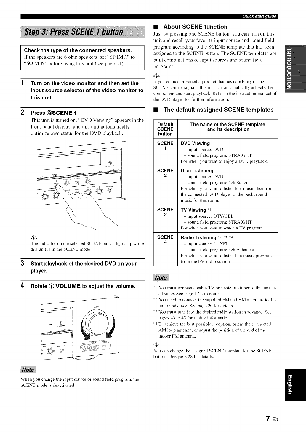
Check the type of the connected speakers.
If the speakers are 6 ohm speakers, set "SP IMP." to
"6_ MIN" before using this unit (see page 21).
1 Turn on the video monitor and then set the
input source selector of the video monitor to
this unit.
2 PressQSCENE 9.
This unit is turned on. "DVD Viewing" appears in the
front panel display, and this unit automatically
optimize own status for the DVD playback.
The indicator on the selected SCENE button lights up while
this unit is ill the SCENE mode.
Start playback of the desired DVD on your
player.
4 Rotate (_) VOLUME to adjust the volume.
When you change the input source or sound field program, the
SCENE mode is deactivated.
'F/R,'lRgril.,,,g;-
• About SCENE function
Just by pressing one SCENE button, you can turn on this
unit and recall your favorite input source and sound field
program according to the SCENE template that has been
assigned to the SCENE button. The SCENE templates are
built combinations of input sources and sound field
programs.
-_,._
If you connect a Yamaha product that has capability of the
SCENE control signals, this unit can automatically activate the
component and start playback. Refer to the instruction manual of
the DVD player for further information.
• The default assigned SCENE templates
Default
SCENE
button
SCENE
1
SCENE
2
SCENE
3
SCENE
4
The name of the SCENE template
and its description
DVD Viewing
- input source: DVD
- sound field program: STRAIGHT
For when you want to enjoy a DVD playback.
Disc Listening
- input source: DVD
- sound field program: 5ch Stereo
For when you want to listen to a music disc from
the connected DVD player as the background
music for this room.
TV Viewing *I
- input source: DTV/CBL
- sound field program: STRAIGHT
For when you want to watch a TV program.
Radio Listening _2, _3,_4
- input source: TUNER
- sound field program: 5ch Enhancer
For when you want to listen to a music program
from the FM radio station.
_1 You must connect a cable TV or a satellite tuner to this unit in
advance. See page 17 for details.
_2 You need to connect the supplied FM and AM antennas to this
unit in advance. See page 20 for details.
_3 You must tune into the desired radio station in advance. See
pages 43 to 45 for tuning information.
_4 To achieve the best possible reception, orient the connected
AM loop antenna, or adjust the position of the end of the
indoor FM antenna.
You can change the assigned SCENE template for the SCENE
buttons. See page 28 for details.
7 En
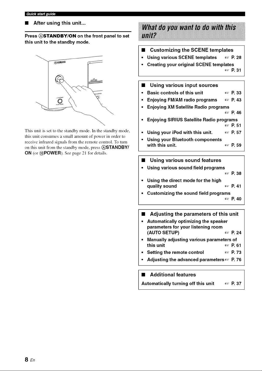
• After using this unit...
Press @STANDBY/ON on the front panel to set
this unit to the standby mode.
"---'_YA_AHA
This unit is set to the standby mode. In the standby mode,
this unit consumes a small amount of power in order to
receive infrared signals from the remote control. To turn
on this unit from the standby mode, press @STANDBY/
ON (or @POWER). See page 21 for details.
• Customizing the SCENE templates
• Using various SCENE templates _' P. 28
• Creating your original SCENE templates
_' P. 31
• Using various input sources
• Basic controls of this unit _' P. 33
• Enjoying FM/AM radio programs _' P. 43
• Enjoying XM Satellite Radio programs
_' P. 46
• Enjoying SIRIUS Satellite Radio programs
_' P. 51
• Using your iPod with this unit. _' P. 57
• Using your Bluetooth components
with this unit. _' P. 59
• Using various sound features
• Using various sound field programs
_' P. 38
• Using the direct mode for the high
quality sound _' P. 41
• Customizing the sound field programs
_' P. 40
• Adjusting the parameters of this unit
• Automatically optimizing the speaker
parameters for your listening room
(AUTO SETUP) _' P. 24
• Manually adjusting various parameters of
this unit _' P. 61
• Setting the remote control _' P. 73
• Adjusting the advanced parameters _' P. 76
• Additional features
Automatically turning off this unit
_' P, 37
SEn
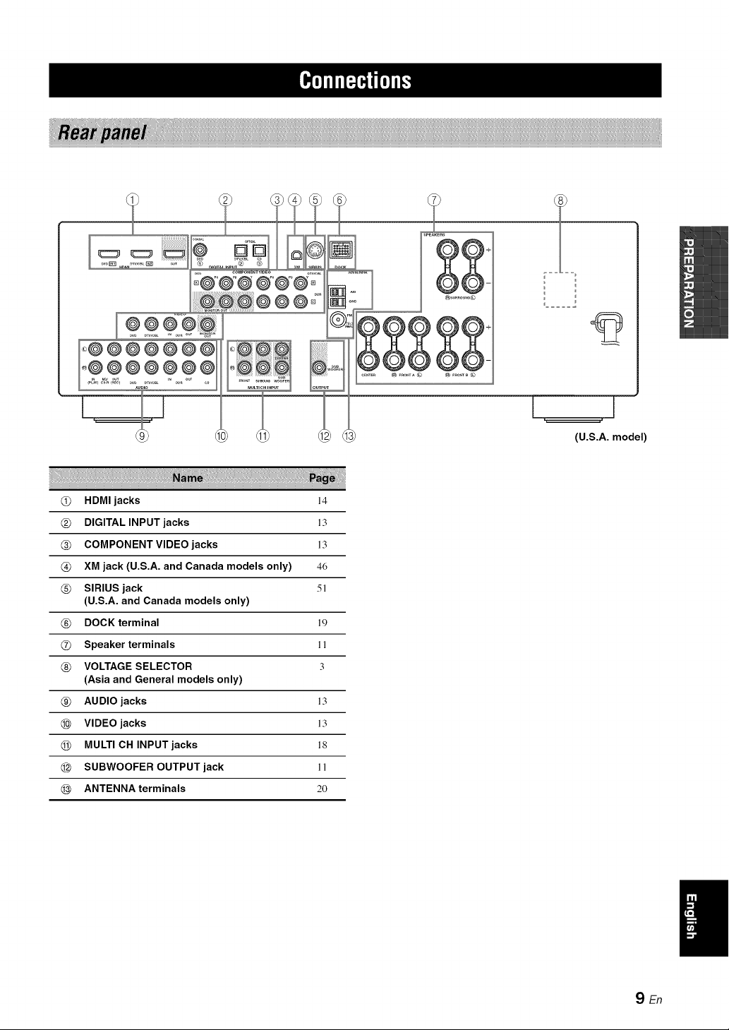
(U.S.A. model)
@ HDMIjacks 14
@ DIGITAL INPUT jacks 13
@ COMPONENT VIDEO jacks 13
@ XM jack (U.S.A. and Canada models only) 46
@ SIRIUS jack 5!
(U.S.A. and Canada models only)
@ DOCK terminal 19
@ Speaker terminals !!
@ VOLTAGE SELECTOR 3
(Asia and General models only)
@ AUDIO jacks !3
@ VIDEO jacks 13
@ MULTI CH INPUT jacks !8
@ SUBWOOFER OUTPUT jack !!
@ ANTENNA terminals 20
SEn
|_i'll If i:I"I_I'll I"
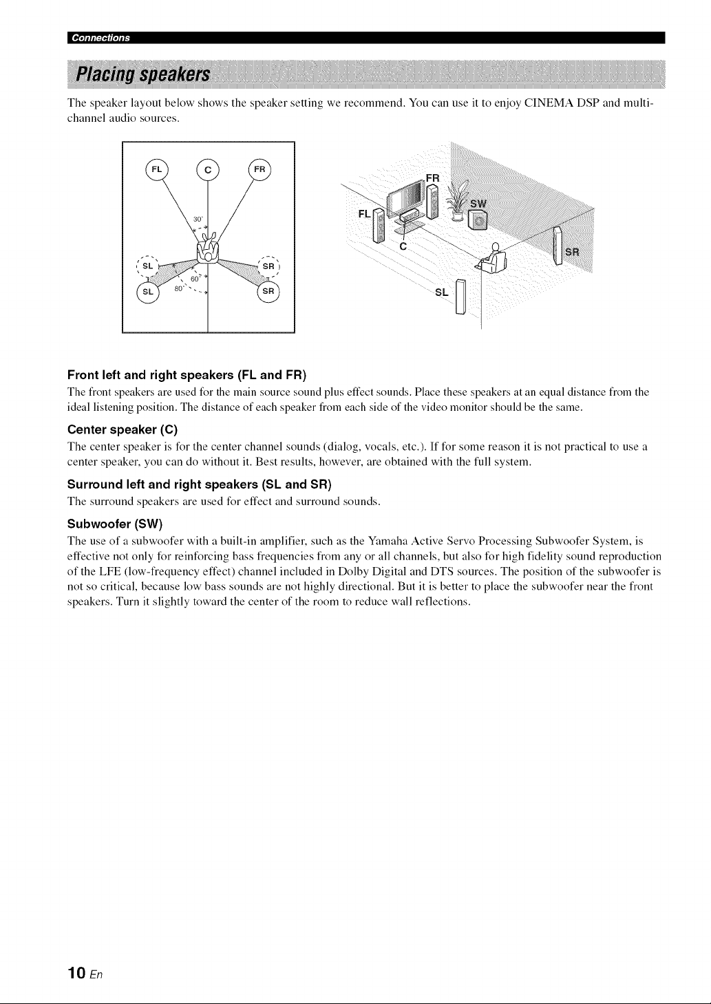
The speaker layout below shows the speaker setting we recommend. You can use it to enjoy CINEMA DSP and multi-
channel audio sources.
30 _
- , 6o_
SL
<,>>>>>>>
Front left and right speakers (FL and FR)
The front speakers are used for the main source sound plus effect sounds. Place these speakers at an equal distance froln the
ideal listening position. The distance of each speaker from each side of the video monitor should be the same.
Center speaker (C)
The center speaker is for the center channel sounds (dialog, vocals, etc.). If for some reason it is not practical to use a
center speaker, you can do without it. Best results, however, are obtained with the full system.
Surround left and right speakers (SL and SR)
The surround speakers are used for effect and surround sounds.
Subwoofer (SW)
The use of a subwoofer with a built-in amplifier, such as the Yamaha Active Servo Processing Subwoofer System, is
effective not only for reinforcing bass frequencies from any or all channels, but also for high fidelity sound reproduction
of the LFE (low-frequency effect) channel included in Dolby Digital and DTS sources. The position of the subwoofer is
not so critical, because low bass sounds are not highly directional. But it is better to place the subwoofer near the front
speakers. Turn it slightly toward the center of the room to reduce wall reflections.
lO En
l'lllll:iill'lli _
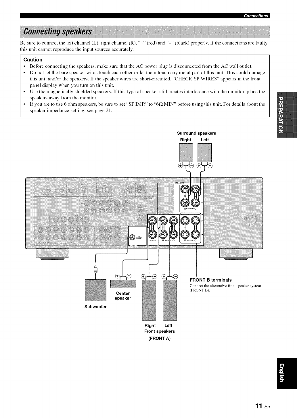
Be sure to connect the left channel (L), right channel (R), "+" (red) and "-" (black) properly. If the connections are faulty,
this unit cannot reproduce the input sources accurately.
Caution
• Before connecting the speakers, make sure that the AC power plug is disconnected from the AC wall outlet.
• Do not let the bare speaker wires touch each other or let them touch any metal part of this unit. This could damage
this unit and/or the speakers. If the speaker wires are short-circuited, "CHECK SP WIRES" appears in the front
panel display when you turn on this unit.
• Use the magnetically shielded speakers. If this type of speaker still creates interference with the monitor, place the
speakers away from the monitor.
• If you are to use 6 ohm speakers, be sure to set "SP IMP." to "6f_ MIN" before using this unit. For details about the
speaker impedance setting, see page 21.
Surround speakers
Right Left
I
Subwoofer
Center
speaker
FRONT B terminals
(7onnecl the alternative front speaker system
(FRONT B).
Right Left
Front speakers
(FRONT A)
I
11 E_
|¶'lllll:l't_|'lll-
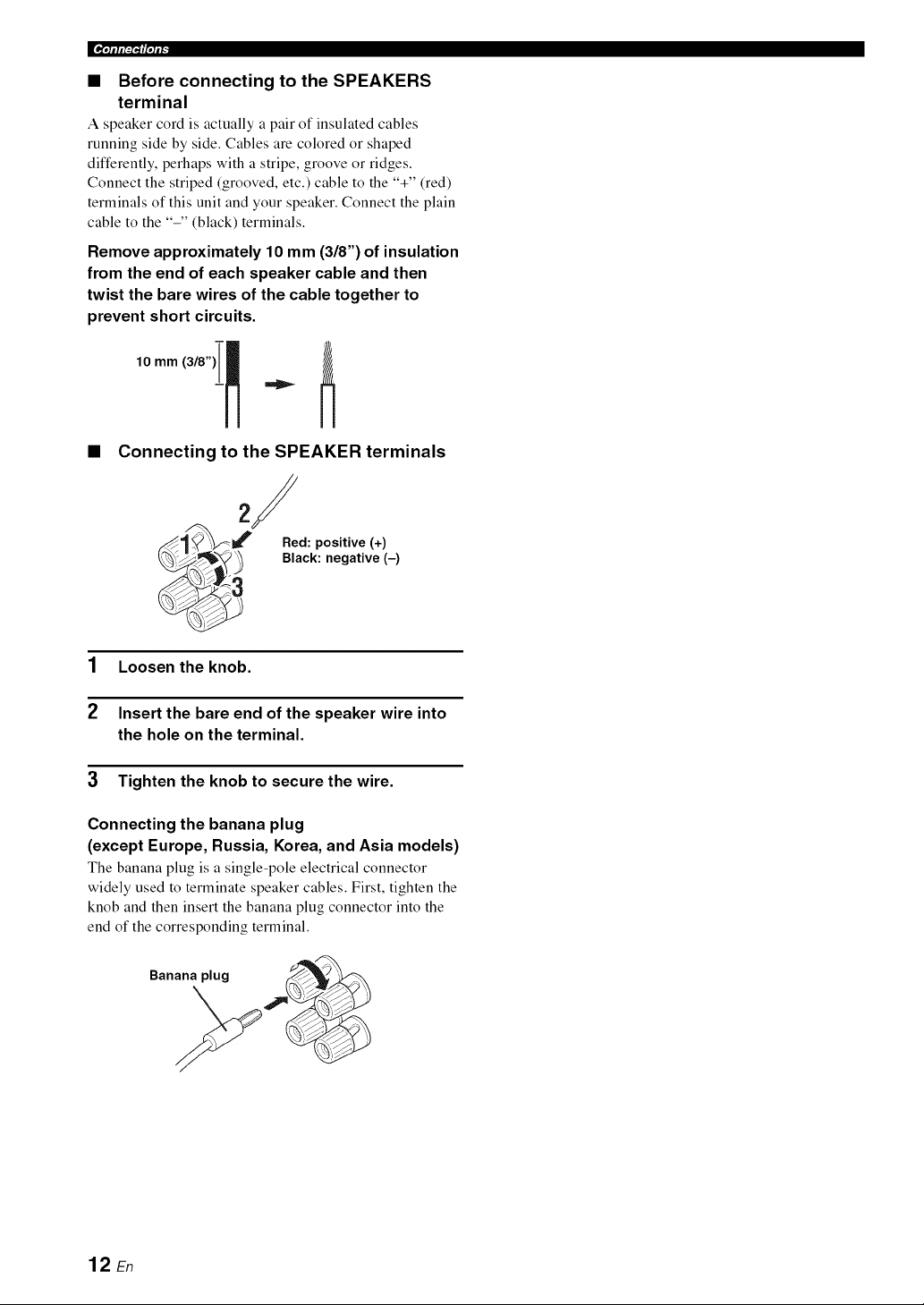
• Before connecting to the SPEAKERS
terminal
A speaker cord is actually a pair of insulated cables
running side by side. Cables are colored or shaped
differently, perhaps with a stripe, groove or ridges.
Connect the striped (grooved, etc.) cable to the "+" (red)
terminals of this unit and your speaker. Connect the plain
cable to the "-" (black) terminals.
Remove approximately 10 mm (3/8") of insulation
from the end of each speaker cable and then
twist the bare wires of the cable together to
prevent short circuits.
10 mm(3/8)i ]
t
• Connecting to the SPEAKER terminals
2/
._/'_' Red: positive (+)
_ Black: negative (-)
1 Loosen the knob.
2 Insert the bare end of the speaker wire into
the hole on the terminal.
3 Tighten the knob to secure the wire.
Connecting the banana plug
(except Europe, Russia, Korea, and Asia models)
The banana plug is a single-pole electrical connector
widely used to terminate speaker cables. First, tighten the
knob and then insert the banana plug connector into the
end of the corresponding terminal.
Banana plug
12 En
lqllll?'lllqli _
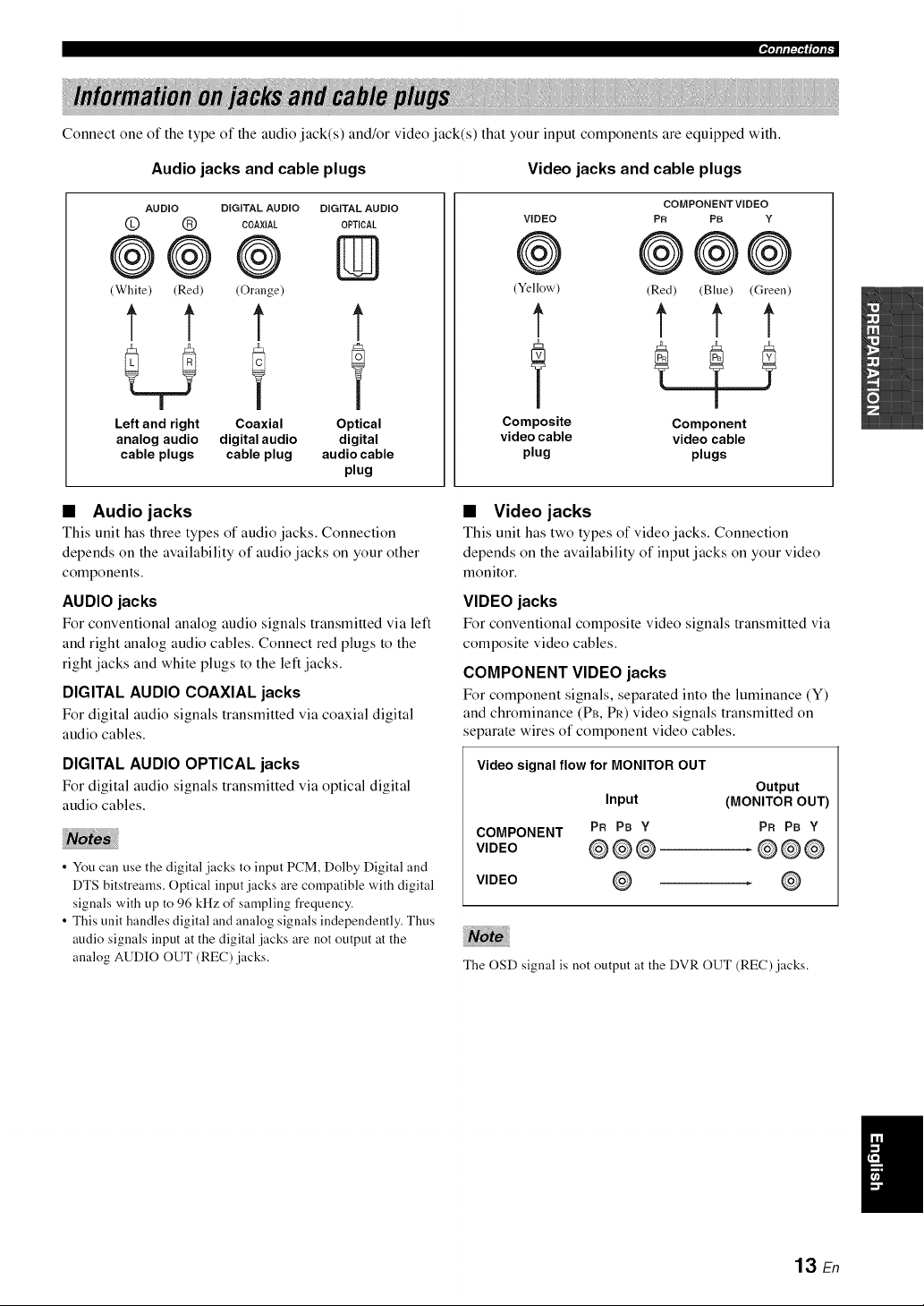
Connect one of the type of the audio jack(s) and/or video jack(s) that your input components are equipped with.
Audio jacks and cable plugs Video jacks and cable plugs
AUDIO DIGITAL AUDIO DIGITALAUDIO
@ (_ COAXIAL OPTICAL
@@@ ID
(White) (Red) (Orange)
t 1' t t
Left and right Coaxial Optical
analog audio digital audio digital
cable plugs cable plug audio cable
plug
COMPONENT VIDEO
VIDEO PR PB Y
@ @@@
(Yellow) (Red) (Blue) (Green)
t t t t
Composite Component
video cable video cable
plug plugs
• Audio jacks
This unit has three types of audio jacks. Connection
depends on the availability of audio jacks on your other
components.
AUDIO jacks
For conventional analog audio signals transmitted via left
and right analog audio cables. Connect red plugs to the
right jacks and white plugs to the left jacks.
DIGITAL AUDIO COAXIAL jacks
For digital audio signals transmitted via coaxial digital
audio cables.
DIGITAL AUDIO OPTICAL jacks
For digital audio signals transmitted via optical digital
audio cables.
• You call use the digital jacks to input PCM, Dolby Digital and
DTS bitstreams. Optical input jacks are compatible with digital
signals with up to 96 kHz of sampling frequency.
• This unit handles digital and analog signals independently. Thus
audio signals input at the digital jacks are not output at the
analog AUDIO OUT (REC) jacks.
• Video jacks
This unit has two types of video jacks. Connection
depends on the availability of input jacks on your video
monitor.
VIDEO jacks
For conventional composite vide() signals transmitted via
composite video cables.
COMPONENT VIDEO jacks
For component signals, separated into the luminance (Y)
and chrominance (PB, PR) video signals transmitted on
separate wires of component video cables.
Video signal flow for MONITOR OUT
Output
Input (MONITOR OUT)
COMPONENT PR PB Y PR PB Y
V,DEO @@@ .@@@
VIDEO @ . @
The OSD signal is not output at the DVR OUT (REC) jacks.
/
13 En
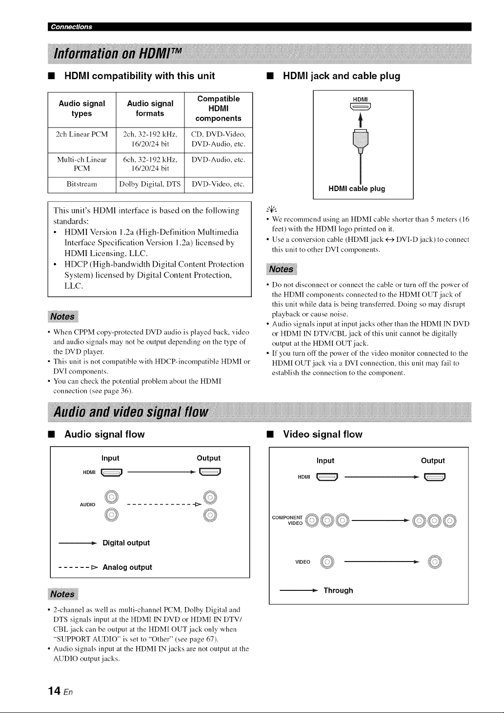
|_i'll If i:I"I_I'll I"
• HDMI compatibility with this unit
Audio signal Audio signal Compatible
HDMI
types formats
components
2ch Linear PCM 2ch, 32-192 kHz, CD, DVD-Video,
16/20/24 bit DVD-Audio, etc.
Multi-ch Linear 6ch, 32-192 kHz, DVD-Audio, etc.
PCM 16/20/24 bit
Bitstream Dolby Digital, DTS DVD-Video, etc.
This unit's HDMI interface is based on the following
standards:
• HDMI Version 1.2a (High-Definition Multimedia
Interface Specification Version 1.2a) licensed by
HDMI Licensing, LLC.
• HDCP (High-bandwidth Digital Content Protection
System) licensed by Digital Content Protection,
LLC.
• When CPPM copy-protected DVD audio is played back, video
and audio signals may not be output depending on the type of
the DVD player.
• This unit is not compatible with HDCP-incompatible HDM[ or
DVI components.
• You call check the potential problem about the HDM[
connection (see page 36).
HDMI jack and cable plug
HDMI
t
HDMI cable plug
• We recommend using an HDM[ cable shorter than 5 meters (16
feet) with the HDM[ logo printed on it.
• Use a conversion cable (HDM[ jack <---)DVI-D jack) to connect
this unit to other DVI components.
iiii
• Do not disconnect or connect the cable or turn off the power of
the HDM[ components connected to the HDM[ OUT jack of
this unit while data is being transferred. Doing so may disrupt
playback or cause noise.
• Audio signals input at input jacks other than the HDM[ IN DVD
or HDM[ IN DTV/CBL jack of this unit cannot be digitally
output at the HDM[ OUT jack.
• If you turn off the power of the video monitor connected to the
HDM[ OUT jack via a DVI connection, this unit may fail to
establish the connection to the component.
• Audio signal flow • Video signal flow
Input Output
AUDIO
---_ Digital output
...... _ Analog output
Input Output
WDEO__
VIDEO
---_ Through
• 2-channel as well as multi-channel PCM, Dolby Digital and
DTS signals input at the HDM[ IN DVD or HDM[ IN DTV/
CBL jack can be output at the HDM[ OUT jack only when
"SUPPORT AUDIO" is set to "Other" (see page 67).
• Audio signals input at the HDM[ IN jacks are not output at the
AUDIO output jacks.
14 En
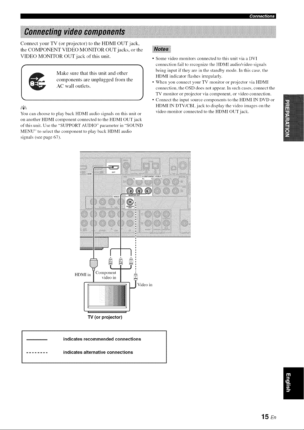
'lqllll:i"lllqli _
Connect your TV (or projector) to the HDMI OUT jack,
the COMPONENT VIDEO MONITOR OUT jacks, or the
VIDEO MONITOR OUT jack of this unit.
Make sure that this unit and other
components are unplugged from the
AC wall outlets.
You can choose to play back HDM[ audio signals on this unit or
on another HDM[ component connected to the HDM[ OUT jack
of this unit. Use the "SUPPORT AUDIO" parameter in "SOUND
MENU" to select the component to play back HDM[ audio
signals (see page 67).
• Some video monitors connected to this unit via a DVI
connection fail to recognize the HDMI audio/video signals
being input if they are ill the standby mode. In this case, the
HDMI indicator flashes irregularly.
• When you connect your TV monitor or projector via HDMI
connection, the OSD does not appear. In such cases, connect the
TV monitor or projector via component, or video connection.
• Connect the input source components to the HDMI IN DVD or
HDMI IN DTV/CBL jack to display the video images on the
video monitor connected to the HDMI OUT jack.
H_.., • Component
L/NIl 111 video in v
TV (or projector)
Video in
indicates recommended connections
indicates alternative connections
15 En
[_i'll If i:I"I _I'll I"
Make sure that this unit and other
components are unplugged from the
AC wall outlets.
• Be sure to make the same type of video connections as those
made for your TV (see page 15).
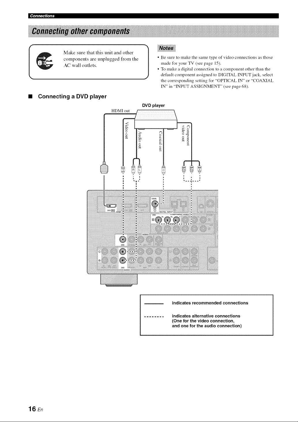
• To make a digital connection to a component other than the
default component assigned to DIGITAL INPUT jack, select
the corresponding setting for "OPTICAL IN" o1""COAXIAL
IN" in "INPUT ASSIGNMENT" (see page 68).
• Connecting a DVD player
DVD player
indicates recommended connections
indicates alternative connections
(One for the video connection,
and one for the audio connection)
16 En
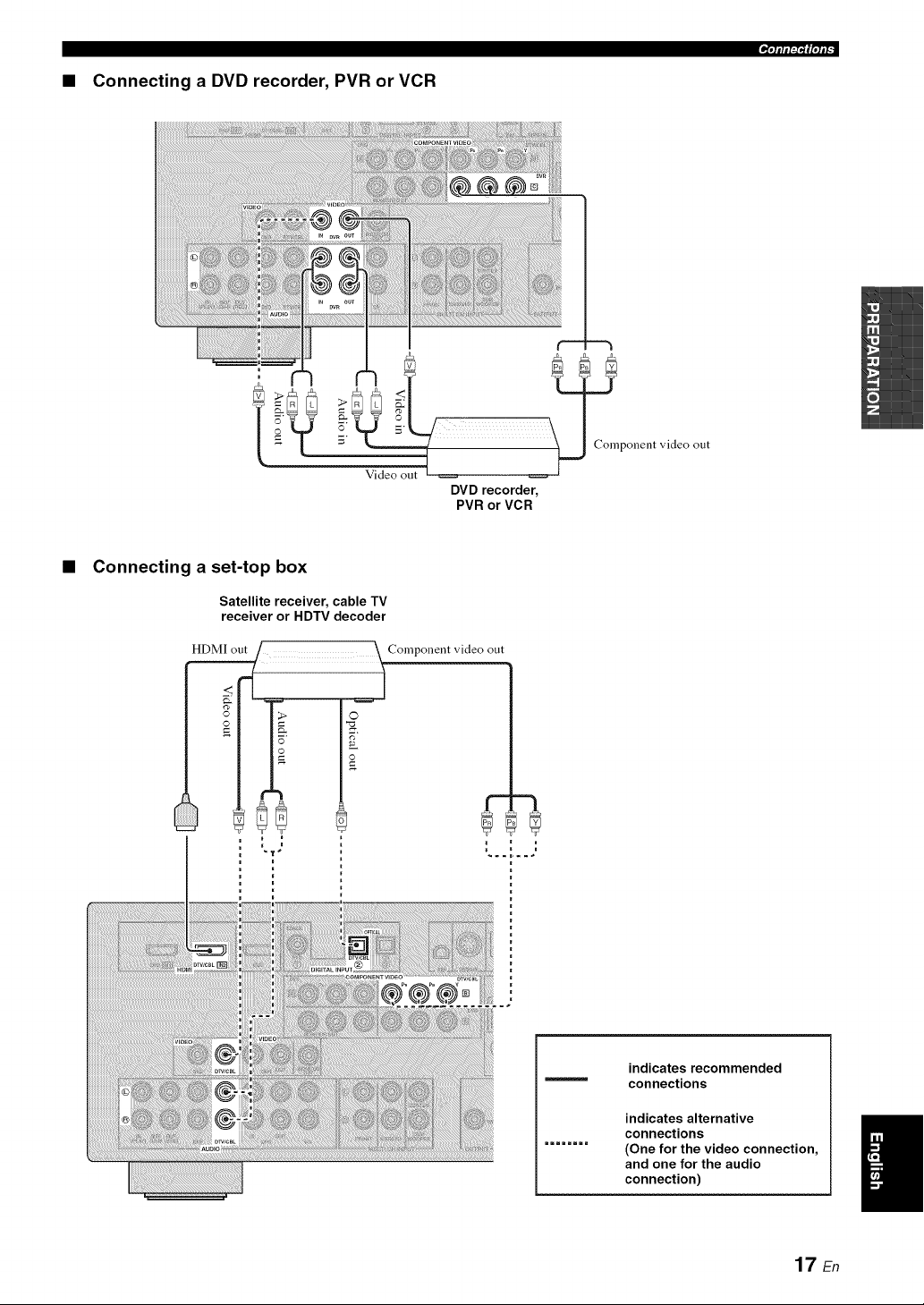
• Connecting a DVD recorder, PVR or VCR
'l'lllll:i"l(lqlF
• Connecting a set-top box
Satellite receiver, cable TV
receiver or HDTV decoder
HDMI
o..[_.:2_..................._ _ompol,ent
m
video out
indicates recommended
connections
indicates alternative
connections
(One for the video connection,
and one for the audio
connection)
17 En
i_i,lllll:l'l_l,lll -
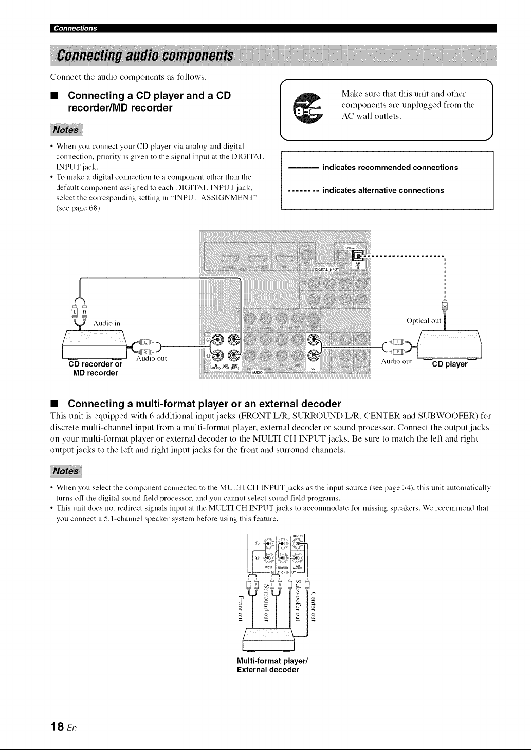
Connect the audio components as follows.
• Connecting a CD player and a CD
recorder/MD recorder
• When you connect your CD player via analog and digital
connection, priority is given to the signal input at the DIGITAL
INPUT jack.
• To make a digital connection to a component other than the
default component assigned to each DIGITAL INPUT jack,
select the corresponding setting in "INPUT ASSIGNMENT"
(see page 68).
Make sure that this unit and other
components are unplugged from the
AC wall outlets.
indicates recommended connections
........ indicates alternative connections
CD recorder or
MD recorder
Audio out CD player
• Connecting a multi-format player or an external decoder
This unit is equipped with 6 additional input jacks (FRONT L/R, SURROUND L/R, CENTER and SUBWOOFER) for
discrete multi-channel input from a multi-format player, external decoder or sound processor. Connect the output j acks
on your multi-format player or external decoder to the MULTI CH INPUT jacks. Be sure to match the left and right
output jacks to the left and right input jacks for the front and surround channels.
• When you select the component connected to the MULTI CH INPUT jacks as the input source (see page 34), this unit automatically
turns off the digital sound field processor, and you cannot select sound field programs.
• This unit does not redirect signals input at the MULTI CH INPUT jacks to accommodate for missing speakers. We recommend that
you connect a 5.l-channel speaker system before using this feature.
k a _Ik al i _ 1
(W
Multi-format player/
External decoder
18 En
'lqllll:i"lllqli _
I Make sure that this unit and other |
1
J
components are unplugged from the
AC wall outlets.
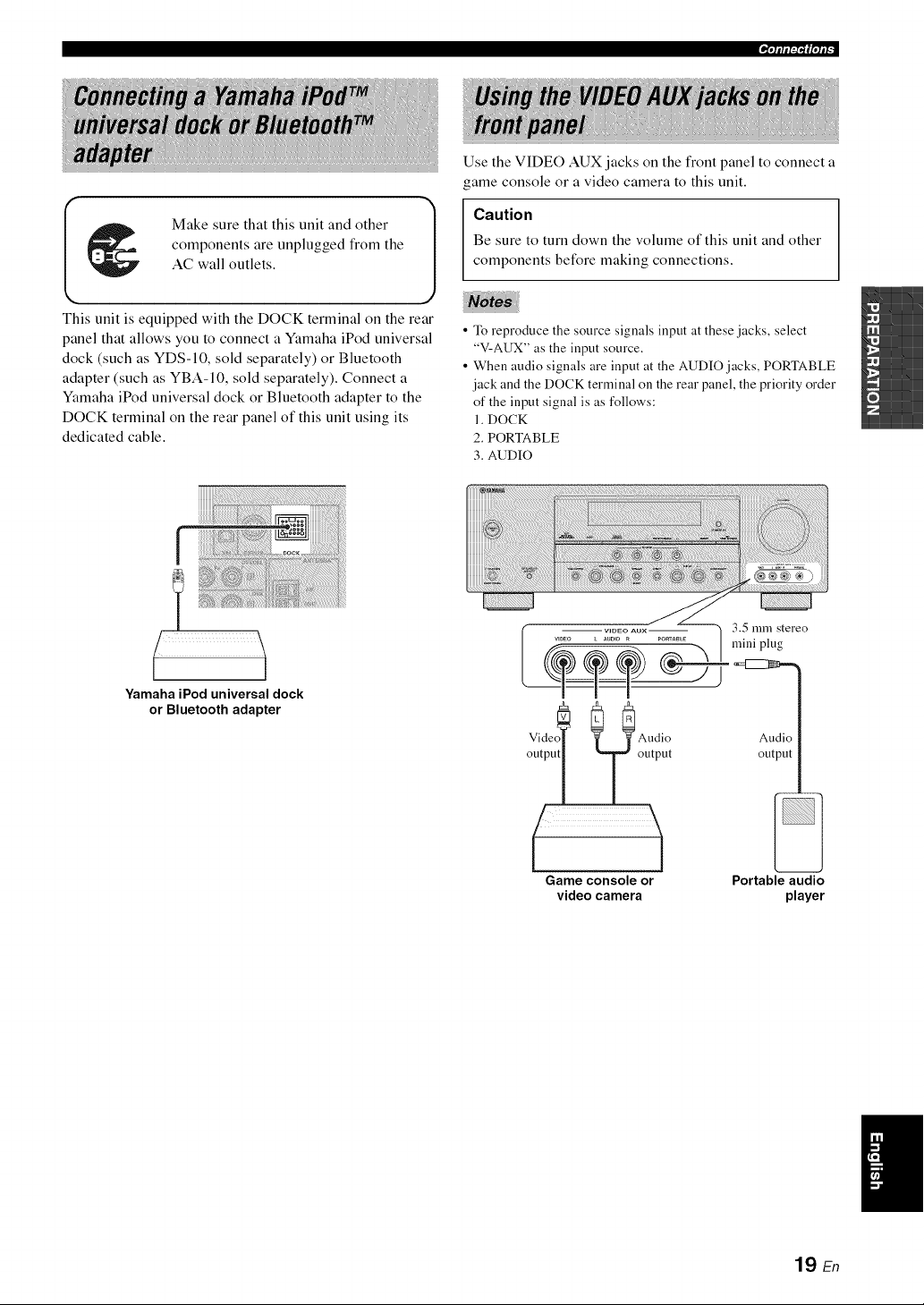
This unit is equipped with the DOCK terminal on the rear
panel that allows you to connect a Yamaha iPod universal
dock (such as YDS-10, sold separately) or Bluetooth
adapter (such as YBA-10, sold separately). Connect a
Yamaha iPod universal dock or Bluetooth adapter to the
DOCK terminal on the rear panel of this unit using its
dedicated cable.
Use the VIDEO AUK jacks on the front panel to connect a
game console or a video camera to this unit.
Caution
Be sure to turn down the volume of this unit and other
components before making connections.
• To reproduce the source signals input at these jacks, select
"V-AUX" as the input source.
• When audio signals are input at the AUDIO jacks, PORTABLE
jack and the DOCK terminal on the rear panel, the priority order
of the input signal is as follows:
1. DOCK
2. PORTABLE
3. AUDIO
r
Yamaha iPod universal dock
or Bluetooth adapter
Audio Audio
output output output
Game console or Portable audio
videocamera player
19 En
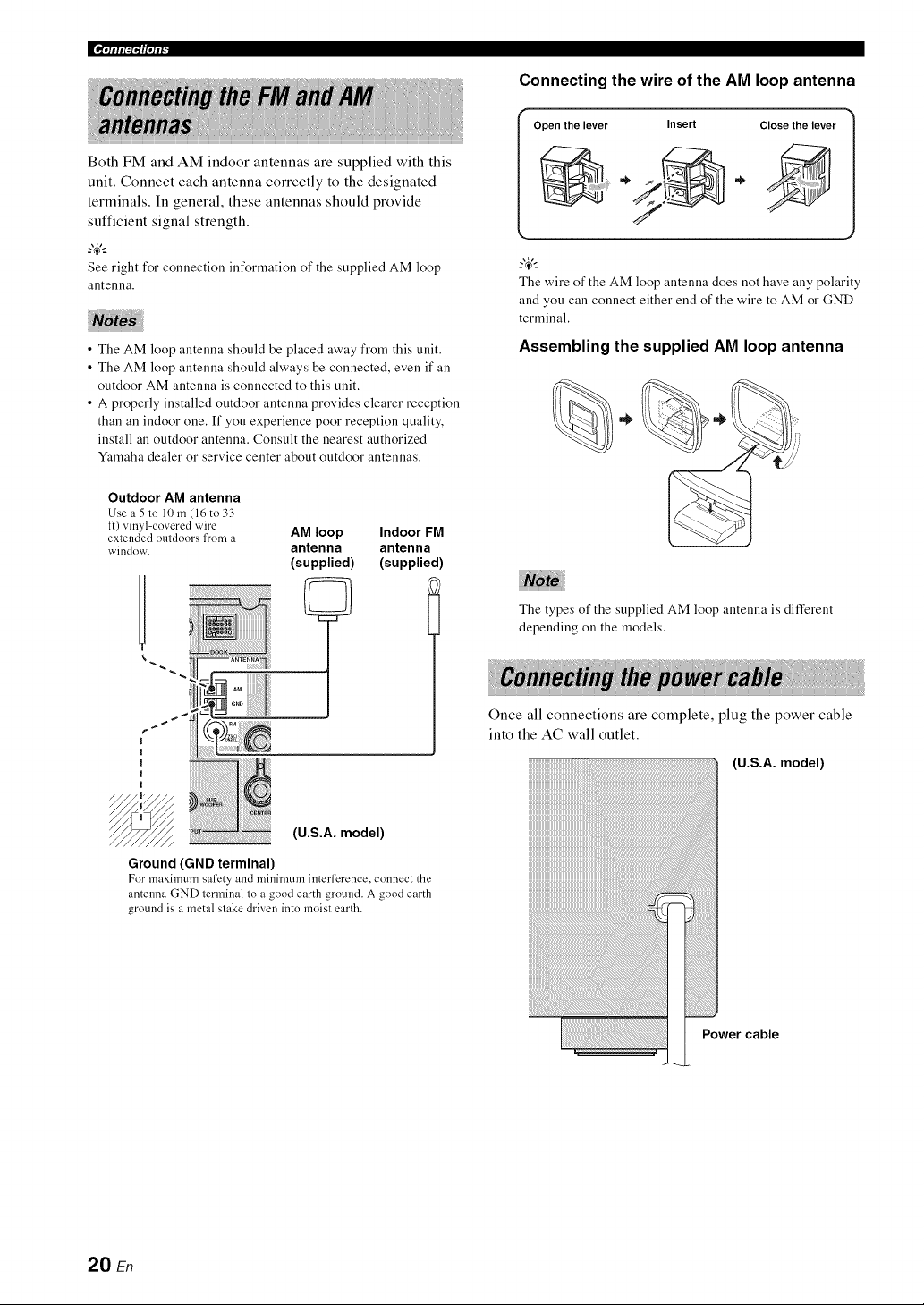
|_iqllll:l"l_lqll"
Both FM and AM indoor antennas are supplied with this
unit. Connect each antenna correctly to the designated
terminals. In general, these antennas should provide
sufficient signal strength.
_.,_,._
See right for connection information of the supplied AM loop
antenna.
• The AM loop antenna should be placed away from this unit.
• The AM loop antenna should always be connected, even if all
outdoor AM antenna is connected to this unit.
• A properly installed outdoor antenna provides clearer reception
than an indoor one. If you experience poor reception quality,
install an outdoor antenna. Consult the nearest authorized
Ymnaha dealer or service center about outdoor antennas.
Connecting the wire of the AM loop antenna
Openthelever Insert Close the lever
@
_.,_,._
The wire of the AM loop antenna does not have any polarity
and you can connect either end of the wire to AM or GND
terminal.
Assembling the supplied AM loop antenna
%.
Outdoor AM antenna
Use a 5 to 10 m (16 to 33
1:) vinyl-covered wire
extended outdoors fl'om a
window.
AM loop Indoor FM
antenna antenna
(supplied) (supplied)
(U.S.A. model)
Ground (GND terminal)
For maximum safety and minimum interference, connect the
antenna GND terminal to a good earth ground. A good earth
ground is a metal stake driven into moist earth.
The types of the supplied AM loop antenna is different
depending on the models.
Once all connections are complete, plug the power cable
into the AC wall outlet.
iiiiiiiiiiiiiiiiiiiiiiiiiiiiiiiiiiiiiiiiiiiiiiiiiiiiiiiiiiiiiiiiiiiiiiiiiiiiiiiiiiiiiiiiiiii_i:i
(U.S.A. model)
Power cable
20 En
'IqIIIFP'IIIqlF
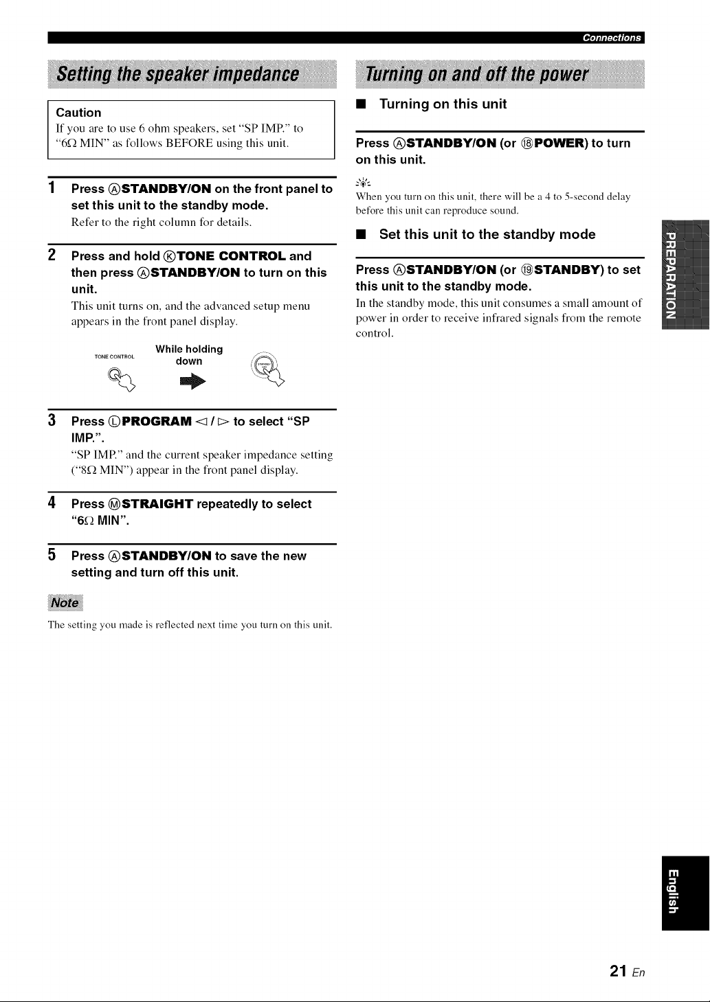
Caution
If you are to use 6 ohm speakers, set "SP IMR" to
"6f_ MIN" as follows BEFORE using this unit.
1 Press @STANDBY/ON on the front panel to
set this unit to the standby mode.
Refer to the right column for details.
2 Press and hold @TONE CONTROL and
then press @STANDBY/ON to turn on this
unit.
This unit turns on, and the advanced setup menu
appears in the front panel display.
• Turning on this unit
Press @STANDBY/ON (or @POWER) to turn
on this unit.
Whileholding
TONE CONTROL down
% ,.
When you turn on this unit, there will be a 4 to 5-second delay
before this unit call reproduce sound.
• Set this unit to the standby mode
Press @STANDBY/ON (or @STANDBY) to set
this unit to the standby mode.
In the standby mode, this unit consumes a small amount of
power in order to receive infrared signals from the remote
control.
Press @PROGRAM <1/I> to select "SP
IMP,".
"SP IMP." and the current speaker impedance setting
("8_ MIN") appear in the front panel display.
4 Press @STRAIGHT repeatedly to select
"6_ MIN".
5 Press @STANDBY/ON to save the new
setting and turn off this unit.
The setting you made is reflected next time you turn on this unit.
/
21 En
|¶,(llll,_l,'l(|qll -
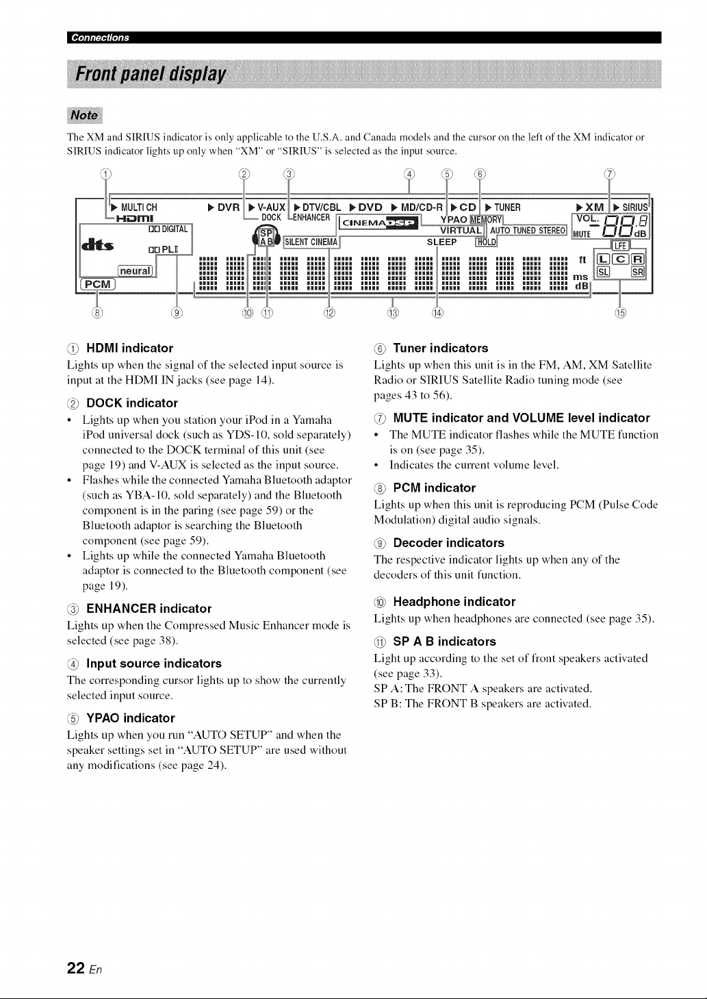
The XM and SIRIUS indicator is only applicable to the U.S.A. and Canada models and the cursor on the left of the XM indicator or
SIRIUS indicator lights up only when "XM" or "SIRIUS" is selected as the input source.
F a: t21C1 t
DIG(TALl __ II IN STE_ Vb_'+'_ ..............
_rl PL_ iilll iilll i iilll iilll iilll iilll iilll iilll iilll iilll iilll iilll iilll
))))))))))))))))))))))))))))))))))))))))))))))))))))))))))))))))))"
mN
)l:lll I:l:l , ,llll Illll Illll Illll Illll Illll Illll Illll Illll Illll Illll dB)
@ HDMI indicator
Lights up when the signal of the selected input source is
input at the HDMI IN jacks (see page 14).
@ DOCK indicator
• Lights up when you station your iPod in a Yamaha
iPod universal dock (such as YDS-10, sold separately)
connected to the DOCK terminal of this unit (see
page 19) and V-AUX is selected as the input source.
• Flashes while the connected Yamaha Bluetooth adaptor
(such as YBA-10, sold separately) and the Bluetooth
component is in the paring (see page 59) or the
Bluetooth adaptor is searching the Bluetooth
component (see page 59).
• Lights up while the connected Yamaha Bluetooth
adaptor is connected to the Bluetooth component (see
page 19).
@ ENHANCER indicator
Lights up when the Compressed Music Enhancer mode is
selected (see page 38).
@ Input source indicators
The corresponding cursor lights up to show the currently
selected input source.
@ YPAO indicator
Lights up when you run "AUTO SETUP" and when the
speaker settings set in "AUTO SETUP" are used without
any modifications (see page 24).
@ Tuner indicators
Lights up when this unit is in the FM, AM, XM Satellite
Radio or SIRIUS Satellite Radio tuning mode (see
pages 43 to 56).
@ MUTE indicator and VOLUME level indicator
• The MUTE indicator flashes while the MUTE function
is on (see page 35).
• Indicates the current volume level.
@ PCM indicator
Lights up when this unit is reproducing PCM (Pulse Code
Modulation) digital audio signals.
@ Decoder indicators
The respective indicator lights up when any of the
decoders of this unit function.
@ Headphone indicator
Lights up when headphones are connected (see page 35).
@ SP A B indicators
Light up according to the set of front speakers activated
(see page 33).
SP A: The FRONT A speakers are activated.
SP B: The FRONT B speakers are activated.
22 En

@ CINEMA DSP indicator
Lights up when you select a CINEMA DSP sound
field program (see page 39).
VIRTUAL indicator
Lights up when Virtual CINEMA DSP is active (see
page 39).
SILENT CINEMA indicator
Lights up when headphones are connected and a
sound field program is selected (see page 39).
Multi-information display
Shows the name of the current sound field program and
other information when adjusting or changing settings.
@ SLEEP indicator
Lights up while the sleep timer is on (see page 37).
@ Input channel and speaker indicators
_LFE indicator
Input channel indicators
Input channel indicators
• Indicate the channel components of the current
digital input signal.
• Light up or flash according to the settings of the
speakers when this unit is in the automatic setup
procedure (see page 24) or the speaker level setting
procedure in the "SP LEVEL" (see page 65).
'_'lflfl_"If|'lfF
• Using the remote control
The remote control transmits a directional infrared ray.
Be sure to aim the remote control directly at the remote
control sensor on this unit during operation.
ApprgXirn_;tg_t_ ]__
@ Infrared window
Outputs infrared control signals. Aim this window at the
component you want to operate.
--'4':
To set the remote control codes for other components, see
page 75.
• Do not spill water or other liquids on the remote control.
• Do not drop the remote control.
• Do not leave or store the remote control in the following types
of conditions:
- places of high humidity, such as near a bath
- places of high temperature, such as near a heater or stove
- places of extremely low temperatures
- dusty places
23 En
This unit employs the YPAO (Yamaha Parametric Room Acoustic Optimizer) technology which lets you avoid
troublesome listening-based speaker setup and achieves highly accurate sound adjustments automatically. The supplied
optimizer microphone collects and this unit analyzes the sound your speakers produce in your actual listening
environment.
• Be advised that it is normal for loud test tones to be output
during the "AUTO SETUP" procedure.
• To achieve the best results, make sure the room is as quiet as
possible while the "AUTO SETUP" procedure is ill progress. If
there is too much ambient noise, the results may not be
satisfactory.
_%,._
You call run "AUTO SETUP" using the system menu that appears
ill the OSD or in the front panel display. This manual uses the
OSD illustrations to explain the "AUTO SETUP" procedure.
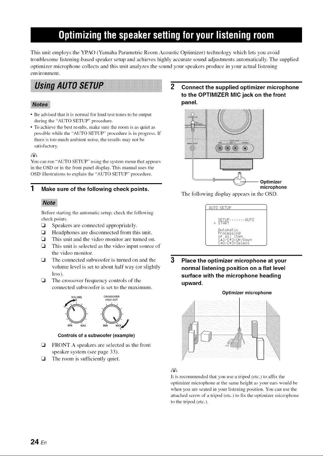
1 Make sure of the following check points.
Connect the supplied optimizer microphone
to the OPTIMIZER MIC jack on the front
panel.
Optimizer
microphone
The following display appears in the OSD.
Before starting the automatic setup, check the following
check points.
Speakers are connected appropriately.
Headphones are disconnected from this unit.
This unit and the video monitor are turned on.
This unit is selected as the video input source of
the video monitor.
The connected subwoofer is turned on and the
volume level is set to about half way (or slightly
less).
The crossover frequency controls of the
connected subwoofer is set to the maximum.
VOLUME CROSSOVER
Controls of a subwoofer (example)
[21 FRONT A speakers are selected as the front
speaker system (see page 33).
[21 The room is sufficiently quiet.
I::*tl-[0 _i_!E'f*..l{'='
:i;Erl..ll::',............ _%1..IT0
_-'k4'[Or,'*ii/'i;i _::;
,:::,'i:r_ll it_em
[i.,i,.]/[?'i" ] :r=I.k*.'i>c,*,4r*
[._i]/[ i,..] _ii;e 1,5_,:::i:,
Place the optimizer microphone at your
normal listening position on a flat level
surface with the microphone heading
upward.
Optimizer microphone
[t is recommended that you use a tripod (etc.) to affix the
optimizer microphone at the same height as your ears would be
when you are seated in your listening position. You can use the
attached screw of a tripod (etc.) to fix the optimizer microphone
to the tripod (etc.).
24 En
P_il_la[.mia[zlk_,Izl_.l:t:tdk_:Jiil_[.lai_l.IOlJl_'_t:lalli[.ml.I.l#r
Make sure that "SETUP" is set to "AUTO"
and the pointer is pointing at "START".
You can also select the following setup methods. [n this
case, press @A to select "SETUP", press @<:1 / 1:>to
select the one of the following choices and then select
"START".
Choices: AUTO, RELOAD, UNDO, DEFAULT
• Select "AUTO" to automatically run the entire
"AUTO SETUP" procedure.
• Select "RELOAD" to reload the last "AUTO
SETUP" settings and override the previous
settings.
• Select "UNDO" to undo the last "AUTO SETUP"
settings and restore the previous settings.
• Select "DEFAULT" to reset the "AUTO SETUP"
parameters to the initial factory settings.
"RELOAD" o1""UNDO" is available only when you have
previously run "AUTO SETUP" and confirmed the results.
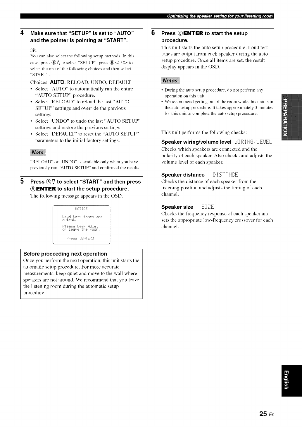
Press @V to select "START" and then press
@ENTER to start the setup procedure.
The following message appears in the OSD.
iqOTICE
OK"¸ ].¢?i_/_..n?? [1"_? K'C*C*_','_,r
F'I' e:_i:_i [:Ei47 li-_;i:?
6
Press @ENTER to start the setup
procedure.
This unit starts the auto setup procedure. Loud test
tones are output from each speaker during the auto
setup procedure. Once all items are set, the result
display appears in the OSD.
• During the auto setup procedure, do not perform any
operation on this unit.
• We recommend getting out of the room while this unit is in
the auto setup procedure. It takes approximately 3 minutes
for this unit to complete the auto setup procedure.
This unit performs the following checks:
Speaker wiring/volume level i.,.ii i::;:i HG,'q....iiiiii.,iiiiilL
Checks which speakers are connected and the
polarity of each speaker. Also checks and adjusts the
volume level of each speaker.
Speaker distance ill:,i STF!HCii.
Checks the distance of each speaker from the
listening position and adjusts the timing of each
channel.
Speaker size :i:.i;i 2=.E
Checks the frequency response of each speaker and
sets the appropriate low-frequency crossover for each
channel.
Before proceeding next operation
Once you perform the next operatkm, this unit starts the
automatic setup procedure. For more accurate
measurements, keep quiet and move to the wall where
speakers are not around. We recommend that you leave
the listening room during the automatic setup
procedure.
25 En
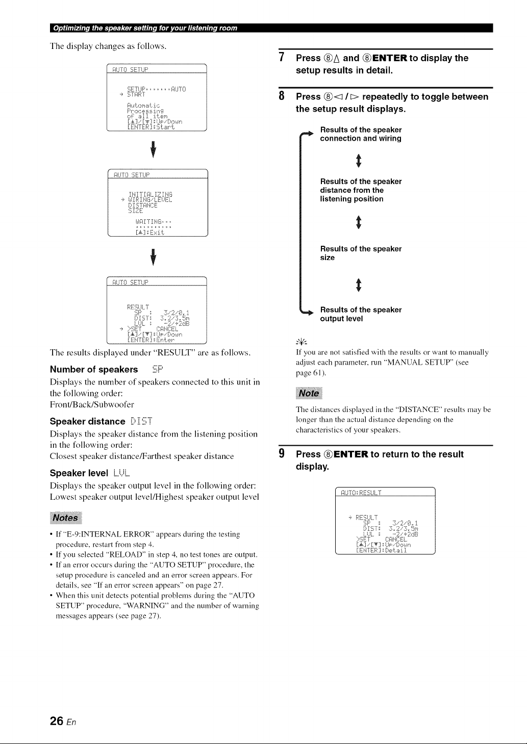
The display changes as follows.
i:_l..ITO:[i;ETI..IF'
:;J:TrL_........ i:_LF[O
'_' gTgRT
PP OC_i,:?i:hiJ._'"1'i_
O'i:: _i_].]. J.i:em
[X.] [,i,'] ',;1.1_: !::,o_.,.m
[ EI'4TIH:_::1x:5[,.._"_[,.
INI7 Ig:_LIZ IHG
,? I.dlRIHG.LEUEL
D IS TgINCE
61E E
}.,.li:_IT ]1HGoo o
_:_1.._'[1::1f];![iT[U P
RE6UL7
DISTs ::Lr 2"'3=r Um
LUL _" ....2. <2dB
':, :::'SEf I:::i:;iIIil:::El.
[:.,k] .. [:'_':i ',',UP i-X::,wn
[:EHTER :i _En i:.e_.
The results displayed under "RESULT" are as follows.
Number of speakers :i:i;P
Displays the number of speakers connected to this unit in
the following order:
Front/B ack/Subwoofer
Speaker distance [):[:iii;i
Displays the speaker distance from the listening position
in the following order:
Closest speaker distance/Farthest speaker distance
Speaker level ,....i...ii....
Displays the speaker output level in the following order:
Lowest speaker output level/Highest speaker output level
• ff "E-9:INTERNAL ERROR" appears during the testing
procedure, restart fi'om step 4.
• ff you selected "RELOAD" in step 4, no test tones are output.
• ff an error occurs during the "AUTO SETUP" procedure, the
setup procedure is canceled and an error screen appears. For
details, see "ff an error screen appears" on page 27.
• When this unit detects potential problems during the "AUTO
SETUP" procedure, "WARNING" and the number of warning
messages appears (see page 27).
Press @A and @ENTER to display the
setup results in detail.
Press @<1 /I:> repeatedly to toggle between
the setup result displays.
Results of the speaker
connection and wiring
Results of the speaker
distance from the
listening position
Results of the speaker
size
=,_ Results of the speaker
output level
-_,;
If you are not satisfied with the results or want to manually
adjust each parameter, run "MANUAL SETUP" (see
page 61 ).
The distances displayed in the "DISTANCE" results may be
longer than the actual distance depending on the
characteristics of your speakers.
Press @ENTER to return to the result
display.
_:ll..i!';::__Rlii::i;LIl..r
':, R_:6UL7
o :2;.-2 .-8,rJ.
:::':!_;Ef {}i:*HI:;EL
[:ENTER:i ',;[:,ei..!ii_:i.1
26 E,",
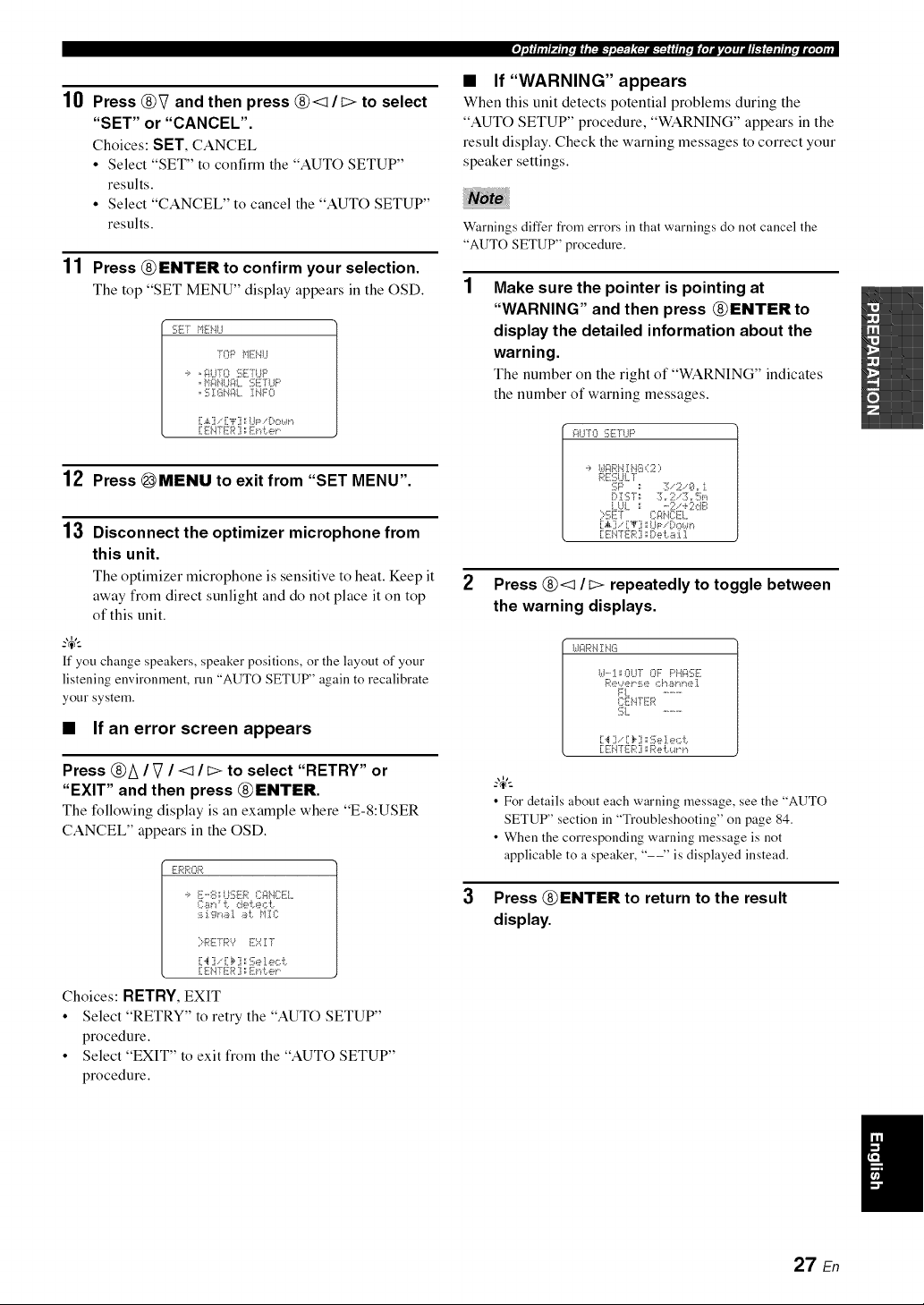
10
11
Press @V and then press @<1/I> to select
"SET" or "CANCEL".
Choices: SET, CANCEL
• Select "SET" to confirm the "AUTO SETUP"
results.
• Select "CANCEL" to cancel the "AUTO SETUP"
results.
Press @ENTER to confirm your selection.
The top "SET MENU" display appears in the OSD.
SET HEHU
]OP _'11ii,.ll..I
,i, , glLF[O ':;F]'LIF'
, g ]X_HI::IL IHF0
[.,i,.] , [i"i"] ::I..ll=, [)own
[:EH-[liFR] : Eni:.er
12 Press _MENU to exit from "SET MENU".
13 Disconnect the optimizer microphone from
this unit.
The optimizer microphone is sensitive to heat. Keep it
away from direct sunlight and do not place it on top
of this unit.
ff you change speakers, speaker positions, or the layout of your
listening environment, run "AUTO SETUP" again to recalibrate
your system.
• If an error screen appears
Press @A / V / <1 / i> to select "RETRY" or
"EXIT" and then press @ENTER.
The following display is an example where "E-8:USER
CANCEL" appears in the OSD.
,--i,-1,-1,-_-.1
m'*R ,R
'_, E'-E ..::'.:;,ED(::FIi'.}CEI....
I]:Br,:' i: de _.e¢ [.
:_i:i.gl"_i_I i_L tl]:C
}RErR9 E::::Zr
[:4 ] , .:_ 7.:::!];e]._,,:::.t.
[:EH-[liFR] : Eni:.er
Choices: RETRY, EXIT
• Select "RETRY" to retry the "AUTO SETUP"
procedure.
• Select "EXIT" to exit from the "AUTO SETUP"
procedure.
P_il_l.t.|l.[:lk_,I@l;(:talk'_:Jiil_[.lal_l.ZelJl_']t:l.llit.ml.I.l#r
• If"WARNING" appears
When this unit detects potential problems during the
"AUTO SETUP" procedure, "WARNING" appears in the
result display. Check the warning messages to correct your
speaker settings.
Warnings differ from errors in that warnings do not cancel the
"AUTO SETUP" procedure.
Make sure the pointer is pointing at
"WARNING" and then press @ENTER to
display the detailed information about the
warning.
The number on the right of "WARNING" indicates
the number of warning messages.
i:_UT0 SE TLIF'
._, I,.II::_RH]:HG (2 ;,
RE:i];U!..T
i..l..!i.. : ....2. +2dB
:::'6ET _:::l:l{.i_:::![-!....
[:.,_.] , .:'_7. .P ,"-, : .n
[:EH-Hi-R] : [:,,>i:._ :i.1
2
3
Press @<1 /I> repeatedly to toggle between
the warning displays.
UF4RHIi'tiii
U'-'I:OUT OF PHi:_SE
b_'ew_i,P:_e *::}'/i_lql./Jie].
FL ...........
CEH[ER
SL ...........
[:'_ ] , [:I__] :::!];eI e,:::i:.
[:EH7 li-R] : R,_H:._.a"n
• For details about each warning message, see the "AUTO
SETUP" section in "Troubleshooting" on page 84,
• When the corresponding warning message is not
applicable to a speaker, "--" is displayed instead.
Press @ENTER to return to the result
display.
I
27 En
This unit is equipped with 17 preset SCENE templates for
various situations of using this unit. As the initial factory
setting, the following SCENE templates are assigned to
each SCENE button:
SCENE 1 : DVD Viewing
SCENE 2: Disc Listening
SCENE 3: TV Viewing
SCENE 4: Radio Listening
If you want to use other SCENE templates, you can select
the desired SCENE templates from the SCENE template
library and assign the templates to the selected SCENE
buttons on the front panel and the remote control.
Select the desired SCENE
template
_ Assign the
SCENE
SCENE template library template to the
(Image) SCENE button
©
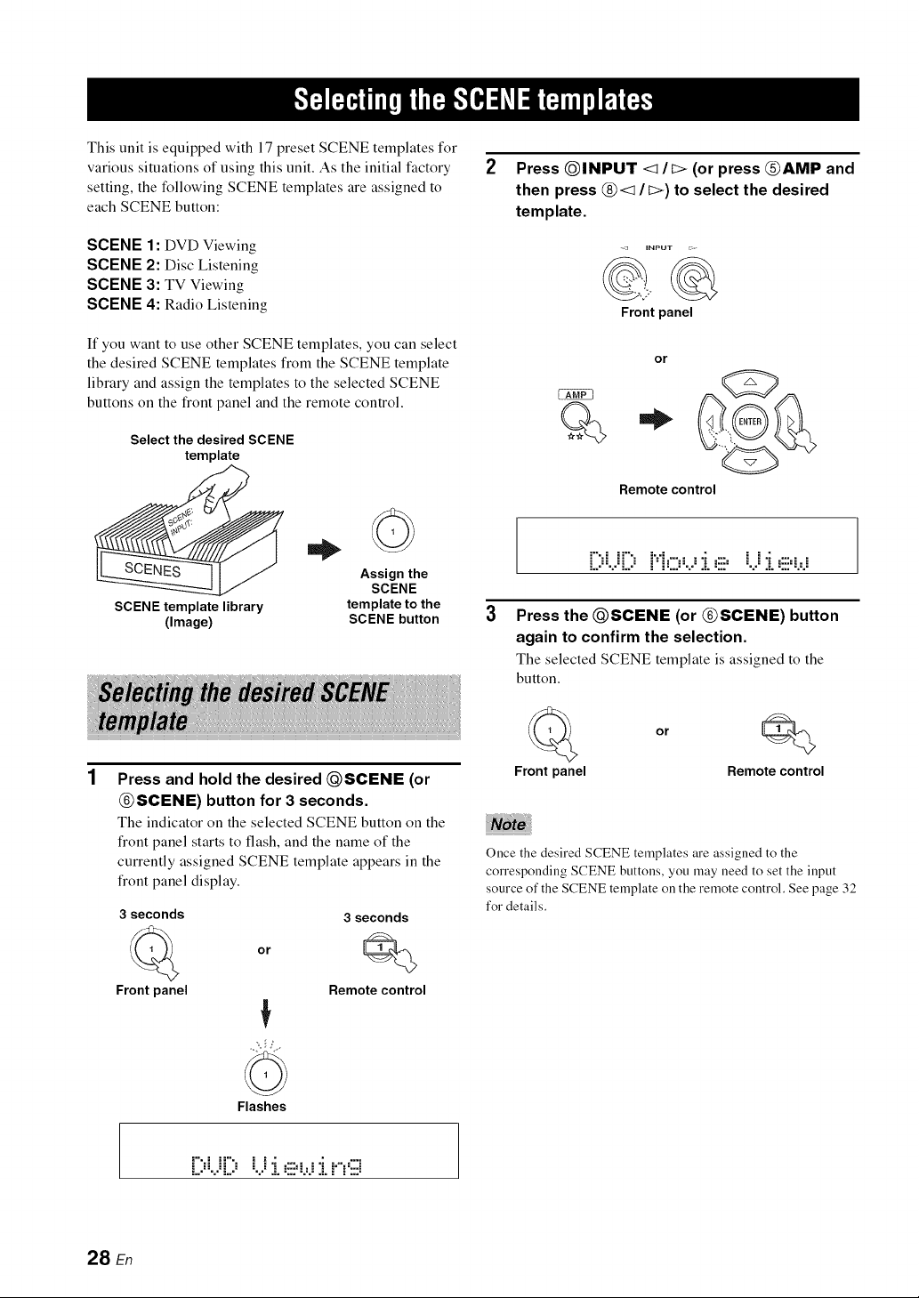
Press and hold the desired QSCENE (or
@SCENE) button for 3 seconds.
The indicator on the selected SCENE button on the
front panel starts to flash, and the name of the
currently assigned SCENE template appears in the
front panel display.
3 seconds 3 seconds
or Q
Front panel Remote control
Press QINPUT <It> (or press @AMP and
then press @< / I>) to select the desired
template.
- _ iNPUT ;:.
Frontpanel
or
Q*
Remote control
[;;i.i[;;H.=:.,.;J..=!ii=B..i
3 Press the @SCENE (or @SCENE) button
again to confirm the selection.
The selected SCENE template is assigned to the
button.
Front panel
or
Q
Remote control
Once the desired SCENE templates are assigned to the
corresponding SCENE buttons, you may need to set the input
source of the SCENE template on the remote control. See page 32
for details.
Flashes
[::¢..ii:::,
28 En
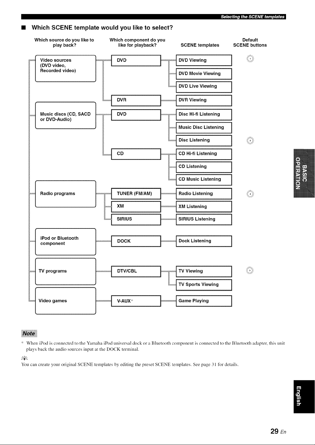
• Which SCENE template would you like to select?
Which source do you like to
play back?
Which component do you
like for playback?
_<_[ Video sources
(DVD video,
Recorded video)
DVD
DVR
DVD
CD
_f Music discs (CD, SACD
or DVD-Audio)
Radio programs
_._I iPod or Bluetooth
component
_<f TV programs
_f Video games
TUNER (FM/AM)
XM
SIRIUS
SCENE templates
DVD Viewing
DVD Movie Viewing
DVD Live Viewing
DVR Viewing
Disc Hi-fi Listening
Music Disc Listening
Disc Listening
CD Hi-fi Listening
CD Listening
CD Music Listening
Radio Listening
XM Listening
SIRIUS Listening
DOCK Dock Listening i
DTV/CBL TV Viewing i
TV Sports Viewing i
V-AUX* Game Playing i
Default
SCENE buttons
* When iPod is connected to the Ymnaha iPod universal dock or a Bluetooth component is connected to the Bluetooth adapter, this unit
plays back the audio sources input at the DOCK terminal.
_%,._
You call create your original SCENE templates by editing the preset SCENE templates. See page 31 for details.
29 En
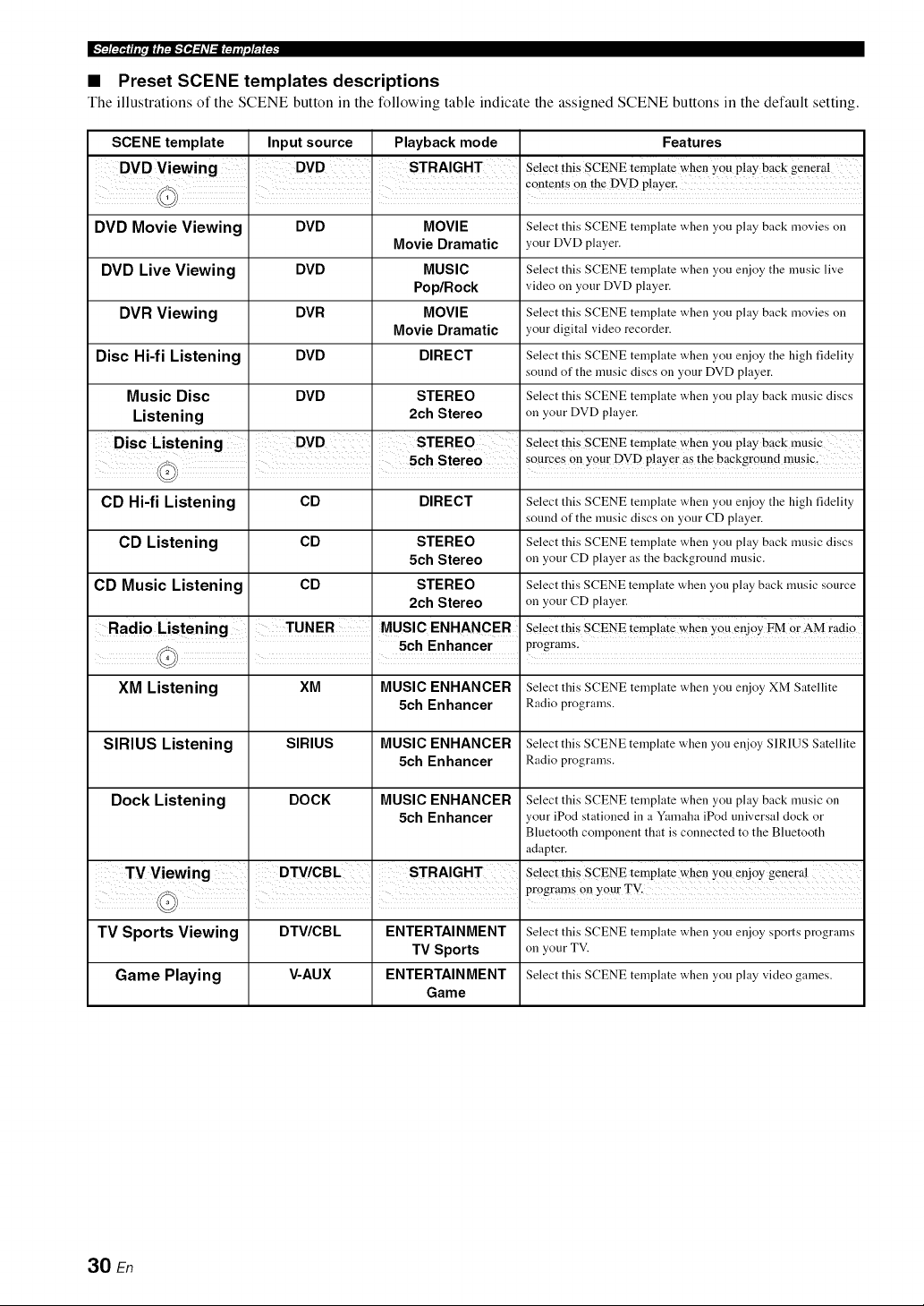
• Preset SCENE templates descriptions
The illustrations of the SCENE button in the following table indicate the assigned SCENE buttons in the default setting.
SCENE template
DVD Movie Viewing
DVD Live Viewing
DVR Viewing
Disc Hi-fi Listening
Music Disc
Listening
CD Hi-fi Listening
CD Listening
CD Music Listening
Input source
DVD
DVD
DVR
DVD
DVD
CD
CD
CD
Playback mode
MOVIE
Movie Dramatic
MUSIC
Pop/Rock
MOVIE
Movie Dramatic
DIRECT
STEREO
2ch Stereo
DIRECT
STEREO
5ch Stereo
STEREO
2ch Stereo
MUSIC ENHANCER
' ' 5ch Enhancer
Features
Select this SCENE template when you play back movies on
your DVD player.
Select this SCENE template when you enjoy the nmsic live
video on your DVD player.
Select this SCENE template when you play back movies on
your digital video recorder.
Select this SCENE template when you enjoy the high fidelity
sound of the mnsic discs on your DVD player.
Select this SCENE template when you play back nmsic discs
on your DVD player.
Select this SCENE template when you play bac k music
Select this SCENE template when you enjoy the high fidelity
sound of the mnsic discs on your CD player.
Select this SCENE template when you play back nmsic discs
on your CD player as the background music.
Select this SCENE template when you play back nmsic source
on your CD player.
Select this SCENE template when You enjoy FM Or AM ladio
programs.
XM Listening XM MUSIC ENHANCER Select this SCENE template when you enjoy XM Satellite
5ch Enhancer Radioprograms.
SIRIUS Listening SIRIUS MUSIC ENHANCER Select this SCENE template when you enjoy SIRIUS Satellite
5ch Enhancer Radioprograms.
Dock Listening DOCK MUSIC ENHANCER Select this SCENE template when you play back nmsic on
5ch Enhancer your iPod stationed in a Yanaaha iPod universal clock or
Bluetooth compouent that is connected to the Blnetooth
adapter.
Select this SCENE temp!ate when you enjoy general
TV Sports Viewing DTV/CBL ENTERTAINMENT Select this SCENE template when you enjoy sports programs
TV Sports on your TV.
Game Playing V-AUX ENTERTAINMENT Select this SCENE template when you play video games.
Game
30 En
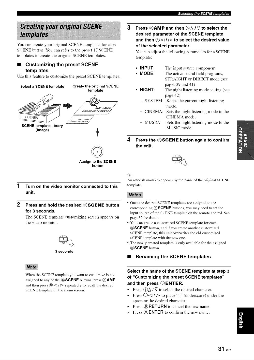
You can create your original SCENE templates for each
SCENE button. You can refer to the preset 17 SCENE
templates to create the original SCENE templates.
• Customizing the preset SCENE
templates
Use this feature to customize the preset SCENE templates.
Select a SCENE template Create the original SCENE
template
SCENE template library
(Image)
Assign to the SCENE
button
Turn on the video monitor connected to this
unit.
Press and hold the desired @SCENE button
for 3 seconds.
The SCENE template customizing screen appears on
the video monitor.
Q
3 seconds
3
Press @AMP and then @A / V to select the
desired parameter of the SCENE template
and then @<1 / I> to select the desired value
of the selected parameter.
You can adjust the following parameters for a SCENE
template:
• INPUT:
• MODE:
• NIGHT:
- SYSTEM:
- CINEMA:
- MUSIC:
The input source component
The active sound field programs,
STRAIGHT or DIRECT mode (see
pages 39 and 41)
The night listening mode setting (see
page 42)
Keeps the current night listening
mode.
Sets the night listening mode to the
CINEMA mode.
Sets the night listening mode to the
MUSIC mode.
4 Press the @SCENE button again to confirm
the edit.
All asterisk mark (*) appears by the name of the original SCENE
template.
• Once the desired SCENE templates are assigned to the
corresponding @SCENE buttons, you may need to set the
input source of the SCENE template on the remote control. See
page 32 for details.
• You can create a customized SCENE template for each
@SCENE button, and if you create another customized
SCENE template, this unit overwrites the old customized
SCENE template with the new one.
• The newly created template is only available for the assigned
@SCENE button.
• Renaming the SCENE templates
When the SCENE template you want to customize is not
assigned to any of the @SCENE buttons, press @AMP
and then press @<1 / t::> repeatedly to recall the desired
SCENE template on the menu screen.
Select the name of the SCENE template at step 3
of "Customizing the preset SCENE templates"
and then press @ENTER.
• Press @A / V to select the desired character.
• Press @<:1 It:> to place "_" (underscore) under the
space or the desired character.
• Press @RETURN to cancel the new name.
• Press @ENTER to confirm the new name.
31 En
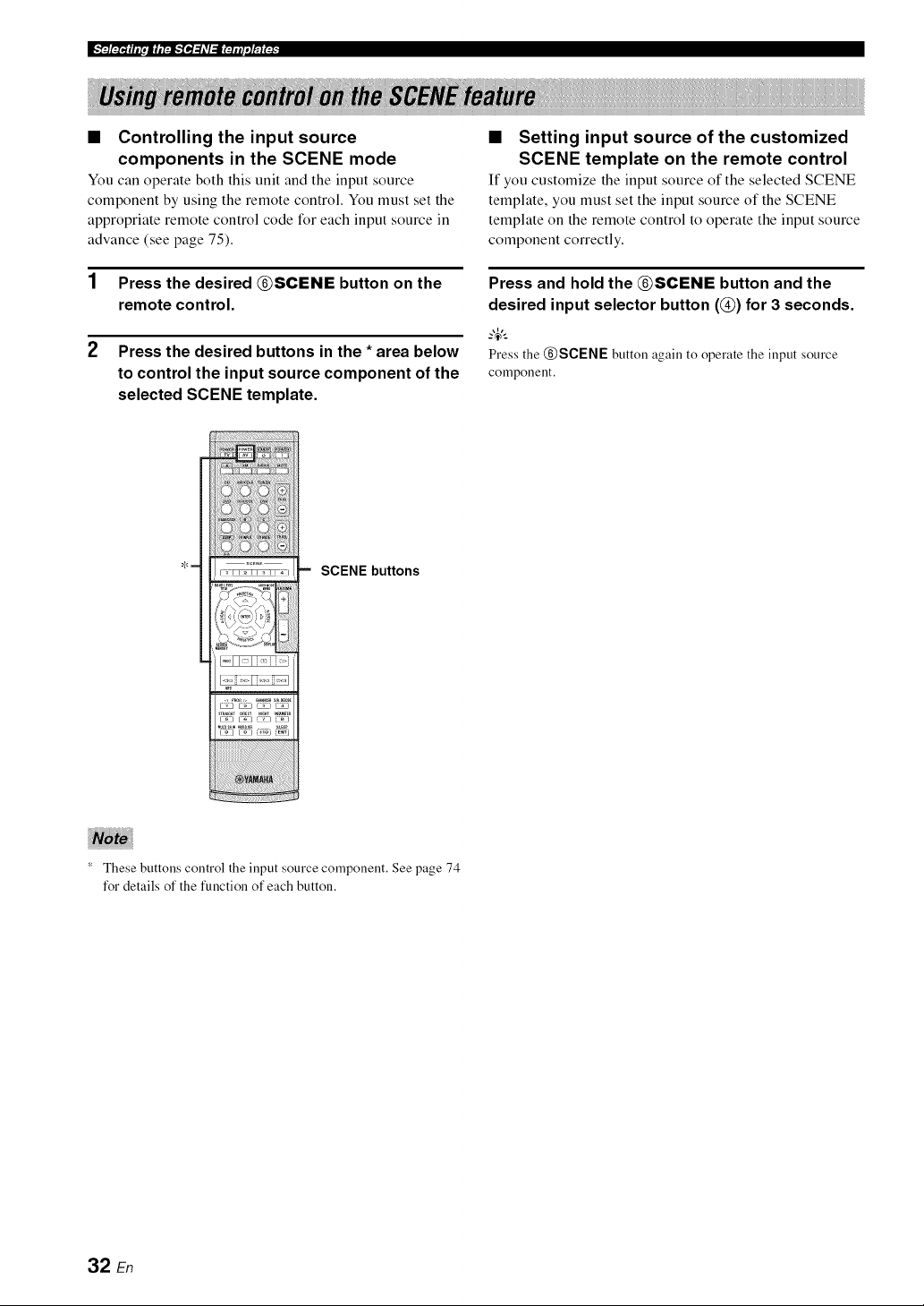
• Controlling the input source
components in the SCENE mode
You can operate both this unit and the input source
component by using the remote control. You must set the
appropriate remote control code for each input source in
advance (see page 75).
1 Press the desired @SCENE button on the
remote control.
2 Press the desired buttons in the * area below
to control the input source component of the
selected SCENE template.
, !! !! !! ! ! ! i i !ii! iiiiiiiiiiiiiiiiiiiiiiiiiiiiiiiiiiiiiiiiiiiiiiiiiiiiiiiiiiiiiiiiiiiiiiiiiiiiiiiiiiiiiiiiiii!i!!
_i_i_i_i_i_i_ii_ii_iiiiiiii_i_i_i!i_!_!_!_!_:!!:i_!_!!!!_!!_!_
m SCENE buttons
• Setting input source of the customized
SCENE template on the remote control
If you customize the input source of the selected SCENE
template, you must set the input source of the SCENE
template on the remote control to operate the input source
component correctly.
Press and hold the @SCENE button and the
desired input selector button (@) for 3 seconds.
_%,;
Press the @SCENE button again to operate the input source
component.
These buttons control the input source component. See page 74
for details of the function of each button.
32 En
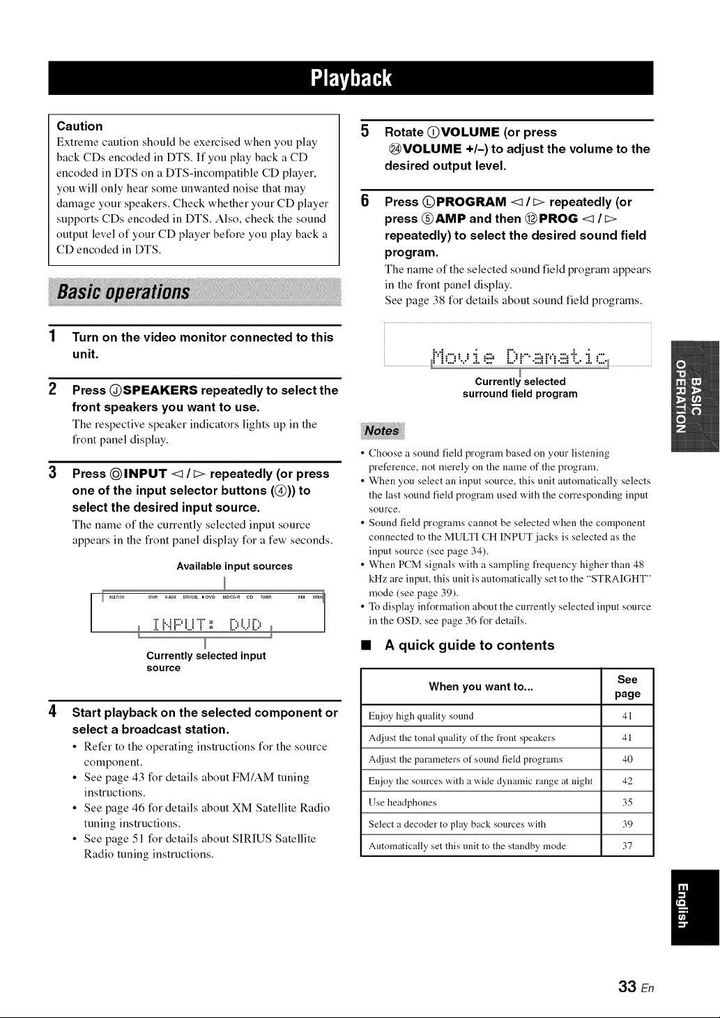
Caution
Extreme caution should be exercised when you play
back CDs encoded in DTS. If you play back a CD
encoded in DTS on a DTS-incompatible CD player,
you will only hear some unwanted noise that may
damage your speakers. Check whether your CD player
supports CDs encoded in DTS. Also, check the sound
output level of your CD player before you play back a
CD encoded in DTS.
1 Turn on the video monitor connected to this
unit.
2 Press @SPEAKERS repeatedly to select the
front speakers you want to use.
The respective speaker indicators lights up in the
front panel display.
Press QINPUT <1/I> repeatedly (or press
one of the input selector buttons (@)) to
select the desired input source.
The name of the currently selected input source
appears in the front panel display for a few seconds.
Available input sources
Dw _Au× DW/CSL_DVD MD/CD-ReD TUN_ ×M _
/
,L i"i i" mj i = L ,= %=L ,=
Currently selected input
source
Start playback on the selected component or
select a broadcast station.
• Refer to the operating instructions for the source
component.
• See page 43 for details about FM/AM tuning
instructions.
• See page 46 for details about XM Satellite Radio
tuning instructions.
• See page 51 for details about SIRIUS Satellite
Radio tuning instructions.
5
6
Rotate @VOLUME (or press
@VOLUME +/-) to adjust the volume to the
desired output level,
Press @PROGRAM <1/I> repeatedly (or
press @AMP and then @PROG <1 It>
repeatedly) to select the desired sound field
program,
The name of the selected sound field program appears
in the front panel display.
See page 38 for details about sound field programs.
M ,..-.: : ._ ...-. r'.::,.......:..,.....,i.._ ....
surround field program
• Choose a sound field program based on your listening
preference, not merely on the name of the program.
• When you select an input source, this unit automatically selects
the last sound field program used with the corresponding input
source.
• Sound field programs cannot be selected when the component
connected to the MULTI CH INPUT jacks is selected as the
input source (see page 34).
• When PCM signals with a sampling frequency higher than 48
kHz are input, this unit is automatically set to the "STRAIGHT"
mode (see page 39).
• To display information about the currently selected input source
in the OSD, see page 36 for details.
• A quick guide to contents
See
When you want to...
page
Enjoy high quality sound 41
Adjust the tonal quality of the front speakers 41
Adjust the parameters of sound field programs 40
Enjoy the sources with a wide dynamic range at night 42
Use headphones 35
Select a decoder to play back sources with 39
Automatically set this unit to the standby mode 37
33 En
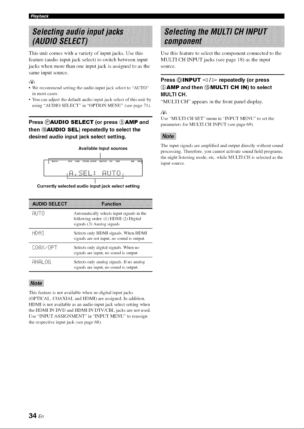
g-amq,N-qi
This unit comes with a variety of input jacks. Use this
feature (audio input jack select) to switch between input
jacks when more than one input jack is assigned to as the
same input source.
--'4'--
• We recommend setting the audio input jack select to "AUTO"
ill most cases.
• You can adjust the default audio input jack select of this unit by
using "AUDIO SELECT" ill "OPTION MENU" (see page 71 ).
Press @AUDIO SELECT (or press @AMP and
then @AUDIO SEL) repeatedly to select the
desired audio input jack select setting.
Available input sources
r Mumc_ Dw _Aux DTWCBL_OVD MD/CD-ReD T_N_ XM _r_1
/
H ,: .::;=i::_.L_ ,, H LJ i LJ
Currently selected audio input jack select setting
Use this feature to select the component connected to the
MULTI CH INPUT jacks (see page 18) as the input
source.
Press @INPUT <1/I> repeatedly (or press
@AMP and then @MULTI CH IN) to select
MULTI CH.
"MULTI CH" appears in the front panel display.
Use "MULTI CH SET" menu in "INPUT MENU" to set the
parameters for MULTI CH INPUT (see page 69).
The input signals are amplified and output directly without sound
processing. Therefore, you cannot activate sound field programs,
the night listening mode, etc. while MULTI CH is selected as the
input source.
1:::1].]"i"i[.[i Automatically selects input signals in the
following order: (1) HDMI (2) Digital
signals (3) Analog signals
{"{[){"{[[ Selects only HDMI signals. When HDMI
signals are not input, no sound is output.
([:([i{:::{'?:',.."([i{:::'"i' Selects only digital signals. When no
signals are input, no sound is output.
{:::{{"{{:::{[..()(:.ii Selects only analog signals. If no analog
signals are input, no sound is output.
This feature is not available when no digital input jacks
(OPTICAL, COAX[AL and HDMD are assigned. [n addition,
HDM[ is not available as an audio input jack select setting when
the HDM[ IN DVD and HDM[ IN DTV/CBL jacks are not used.
Use "INPUT ASSIGNMENT" in "INPUT MENU" to reassign
the respective input jack (see page 68).
34 En
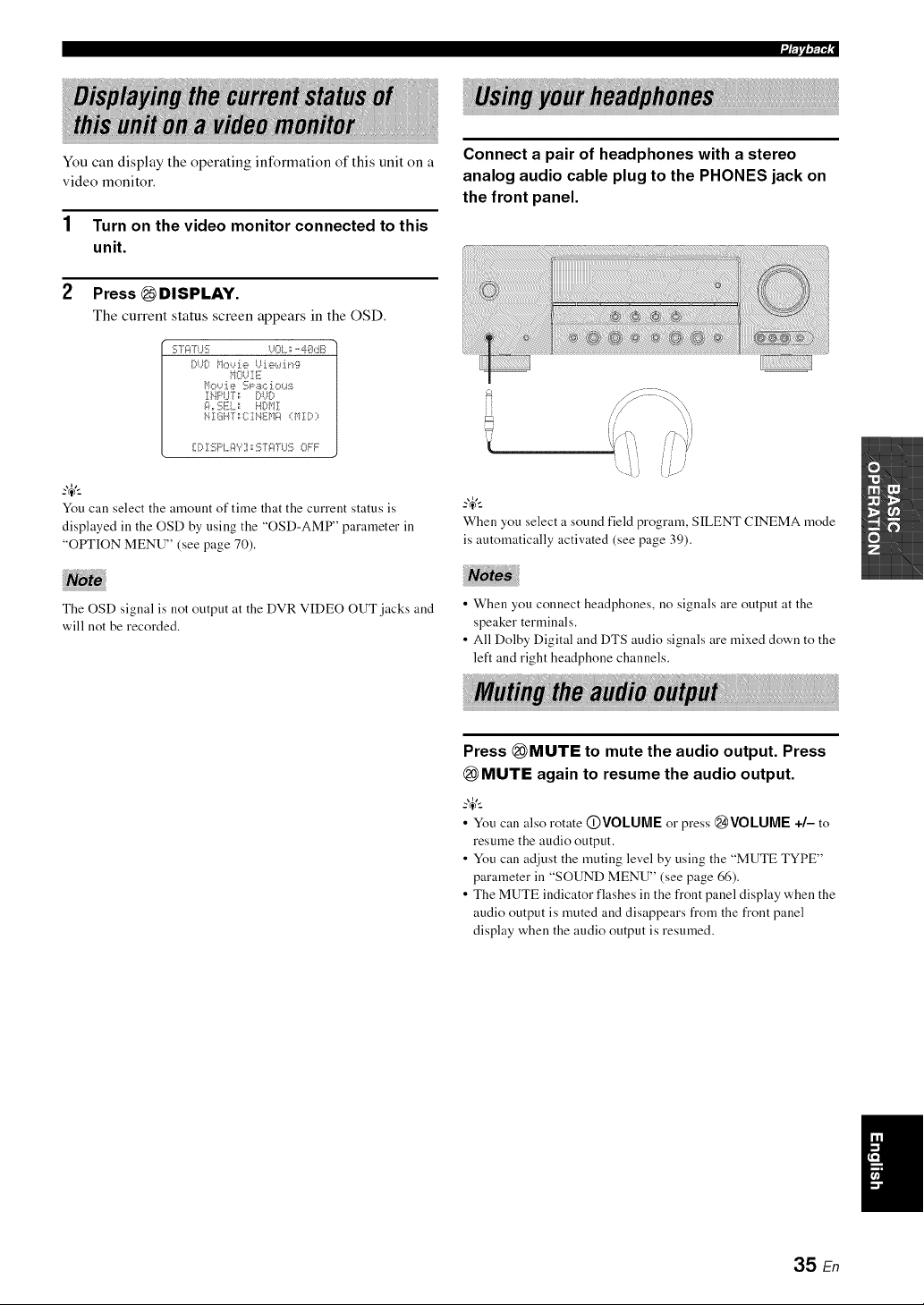
You can display the operating information of this unit on a
video monitor.
1 Turn on the video monitor connected to this
unit.
2 Press _DISPLAY.
The current status screen appears in the OSD.
i_r'rlv,7;r4:
:!!;7gIT{.IS U0L: -'4@dB
OUO M,>..deUiewir,g
MOUIE
_i{=rSE[. _ HO{r!l
NII]i.{[: CIi'_liMg (MID;=
l[.[ ,11 .,, io f..,_ :> OFF
You can select the amount of time that the current status is
displayed in the OSD by using the "OSD-AMP" parameter in
"OPTION MENU" (see page 70).
The OSD signal is not output at the DVR VIDEO OUT jacks and
will not be recorded.
Connect a pair of headphones with a stereo
analog audio cable plug to the PHONES jack on
the front panel.
When you select a sound field program, SILENT CINEMA mode
is automatically activated (see page 39).
• When you connect headphones, no signals are output at the
speaker terminals.
• All Dolby Digital and DTS audio signals are mixed down to the
left and right headphone channels.
Press (_MUTE to mute the audio output. Press
(_MUTE again to resume the audio output.
• You can also rotate (])VOLUME or press @VOLUME +/- to
resume the audio output.
• You can adjust the muting level by using the "MUTE TYPE"
parameter in "SOUND MENU" (see page 66).
• The MUTE indicator flashes in the front panel display when the
audio output is muted and disappears from the front panel
display when the audio output is resumed.
35 En
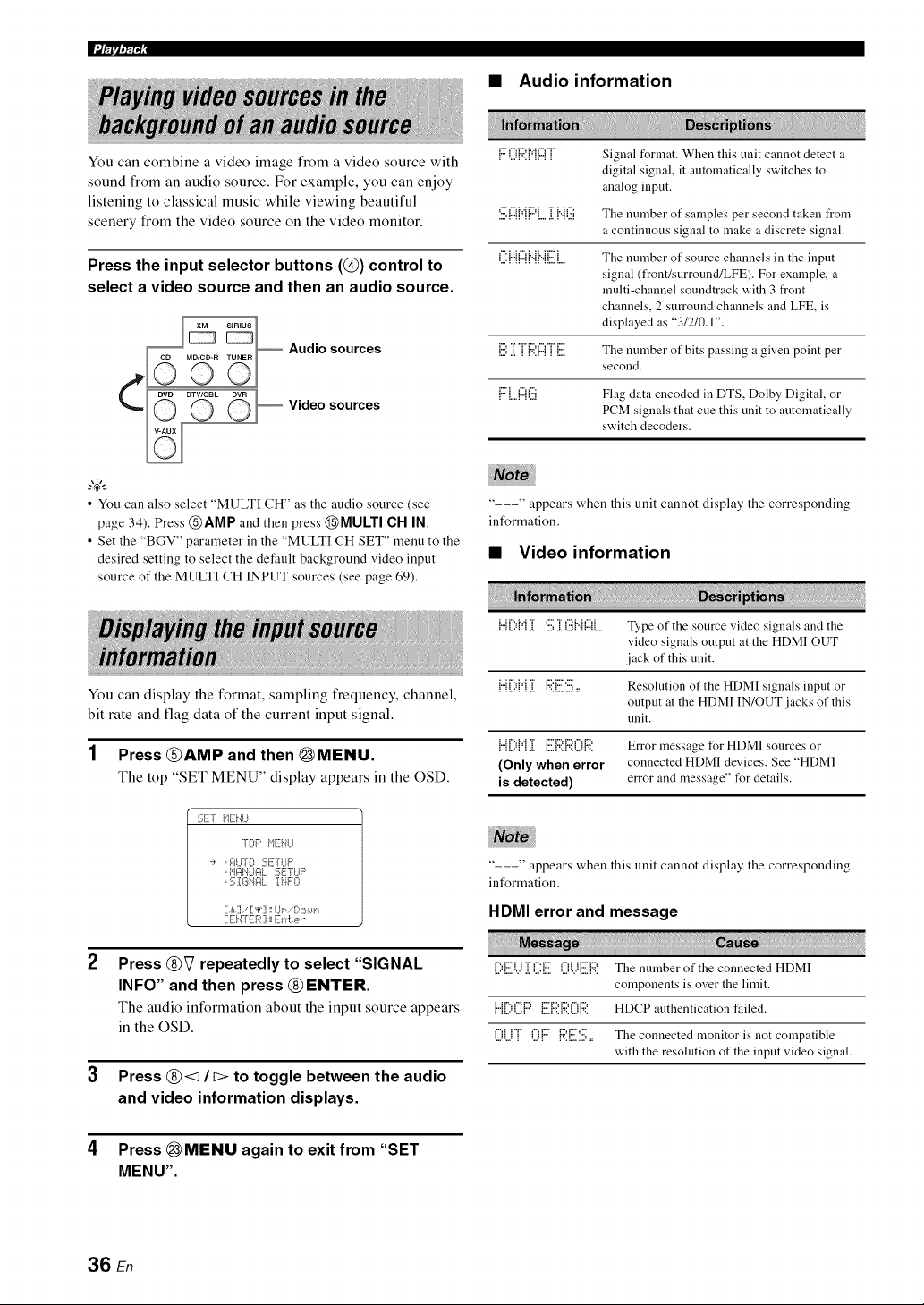
lumq,_i
• Audio information
You can combine a video image from a video source with
sound from an audio source. For example, you can enjoy
listening to classical music while viewing beautiful
scenery from the video source on the video monitor.
Press the input selector buttons (@) control to
select a video source and then an audio source.
Audio sources
Video sources
F0{::4'.M{:::{] Signal format. When this unit cannot detect a
digital signal, it autonaatically switches to
analog input.
'.iii;{:::{{"{{:::'{....][ {"{G The mnnber of samples per second taken from
a continuous signal to make a discrete signal.
(]:HIZI{".{{".{EL The number of source channels in the input
signal (front/surround/LFE). For example, a
multi-channel soundtrack with 3 front
channels, 2 surround channels and LFE, is
displayed as "31210.1".
[:.i:]]]"{::4'.1:::1]"[.. The number of bits passing a given point per
second.
FLlZ{(iii Flag data encoded in DTS, Dolby Digital, or
PCM signals that cue this unit to automatically
switch decoders.
• You can also select "MULTI CH" as the audio source (see
page 34), Press @AMP and then press @MULTI CH IN,
• Set the "BGV" parameter in the "MULTI CH SET" menu to the
desired setting to select the default background video input
source of the MULTI CH INPUT sources (see page 69),
You can display the format, sampling frequency, channel,
bit rate and flag data of the current input signal.
1 Press @AMP and then @MENU.
The top "SET MENU" display appears in the OSD.
---" appears when this unit cannot display the corresponding
information.
• Video information
2
3
SET _1Ei'_U
]-OF' _'11ii,.ll..I
,i, , _:ILITO SF]'LIF'
, :;ISN¢IL INFO
[A] , ["F] 1;I..ll;:,, [:_,::,J.,._t,
[ EI.I-I'E{z_:] : Er&er
Press @V repeatedly to select "SIGNAL
INFO" and then press @ENTER.
The audio information about the input source appears
in the OSD.
Press @<:1/b> to toggle between the audio
and video information displays.
1"11][:'1"1][ :iii;][(iii{"{!:::!LType of the source video signals and the
video signals output at the HDMI OUT
jack of this unit.
{...{[:,{v{[[ {:'4'.E'}.:,,, Resolution of the HDMI signals input or
output at the HDMI IN/OUT jacks of this
unit.
{"{[:'i"i]] [ii]:;;2i:42i]){:4: Error message for HDMI sources or
(Only when error connected HDMI devices. See "HDMI
is detected) error and message" t_r details.
---" appears when this unit cannot display the corresponding
information.
HDMI error and message
[:,EU ]](.]:E 0UER The number of the connected HDMI
components is over the limit.
{"{[:'i]]:F' E{:;?,{:;?,i]){:;?. HDCP authentication failed.
()U]" ()F {:4'.E'.i.:,,, The connected monitor is not compatible
with the resolution of the input video signal.
4 Press (_MENU again to exit from "SET
MENU".
36 En
Use this feature to automatically set this unit to the
standby mode after a certain amount of time.
i/Flv,7_r4:
Press _AMP and then press _SLEEP
repeatedly to set the amount of time.
Each time you press _SLEEP, the front panel display
changes as shown below.
The SLEEP indicator flashes while you are switching the
amount of time for the sleep timer. Once the sleep timer is
set, the SLEEP indicator lights up in the front panel
display, and the display returns to the selected sound field
program.
_%,._
• To cancel the sleep timer, press @AMP and then press
@SLEEP repeatedly until "SLEEP OFF" appears ill the front
panel display.
• The sleep timer setting can also be canceled bypressing
QSTANDBY/ON (or @STANDBY) to set this unit to the
standby mode.
37 En
This unit is equipped with a variety of precise digital
decoders that allow you to enjoy multi-channel playback
from almost any stereo or multi-channel sound source.
Press OPROGRAM <1 It> (or press @AMP and
then press @ PROG <1/t> repeatedly).
The name of the selected sound field program appears in
the front panel display.
• When you select all input source, this unit automatically selects
the last sound field program used with the corresponding input
source.
• Sound field programs cannot be selected when the component
connected to the MULTI CH INPUT jacks is selected as the
input source (see page 34).
• When PCM signals with a sampling frequency higher than 48
kHz are input, this unit is automatically set to the "STRAIGHT"
)node (see page 39).
_%,._
Choose a sound field program based on your listening preference,
not merely on the name of the program itself.
{:::'OF::'.."ROC.{.:i CINEMA DSP processing. This program presents an image nl pnp, rock, or jazz live
conceri. The sound field reproduces tile spaciousness nf a massive pavilion with an emphasis
on tile vividness nl vocals l>11the stage and snlo instruments and the beats of rhythm
instrument s.
MUSIC {{.!:.!_ii. ii. CINEMA DSP prncessing. This snund field is suitable 12!I"classic and orcbestral music. Tile
program uses data collected in a large concerl hall in Munich. You can enjoy delicate and
beautiful reverberatinn and a majestic atmospbere.
•.i[.!'.!!7:117 CINEMA DSP processing. The snund field is suitable fnr jazz and fusion music. It uses data
cnllecled in a 17.unousjazz club in New York. You can enjoy clear reverberation.
(:.ii.!:.!!p'!_!::= CINEMA DSP processing. You can enjoy dynamic and thrilling sound effecls as yon play
games. The program lets ynu feel the depth and three-dimensinnal surrnunding sounds of the
field where you are playing, and nffers cinema-like surrounding sound effects lk)r tile scenes
nf movies.
ENTERTAINMENT
'r"i.) s F:O DIL.:!:.!. CINEMA DSP processing. You can enjoy sports relays broadcast in steren and variety shows
with a live sound environment. For sports relays, the voices l>1cnmmentalors and
announcers come clearly fl'om the center: Ihe cheers and atmosphere in tile stadium spread
around within a comfortable range, and you can feel like as ilynu are in the stadium.
{'@"...'ii.'!:2 SF::'.!:.!!'I".ii.OL.!:!:.!. CINEMA DSP processing. The smmd field is suitable for movies with an emphasis on
speclacular sound effecls, and is a perfecl fit with a wide screen. The program reproduces a
wide dynamic range lrom minimum sound effects to powerhd sounds.
MOVIE {"l,:v..,:i.,!:? [)F.!:!ffq.!.!_i:..:i.,:. CINEMA DSP processing. This sound field is also suitable for movies with an emphasis on
three-dimensional sound effects. It restrains reverberatinn to an mnderate extent, blAl
reproduces sound effects and background music in a soft. three-dimensional manner with
clarity and center orientation nl voices as pivnls.
2C.{"! S'iL._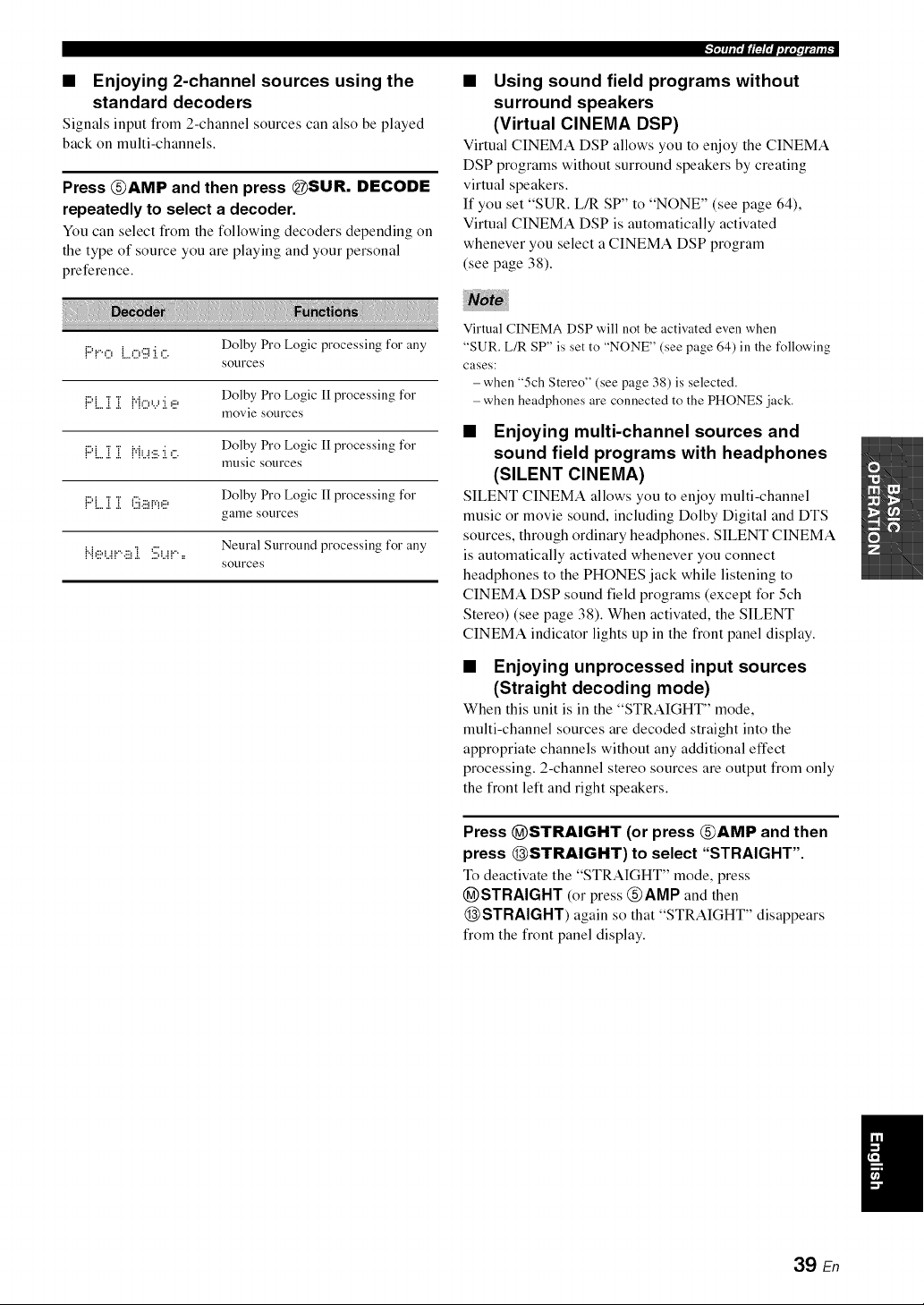
• Enjoying 2-channel sources using the
standard decoders
Signals input from 2-channel sources can also be played
back on multi-channels.
Press @AMP and then press @SUR. DECODE
repeatedly to select a decoder.
You can select from the following decoders depending on
the type of source you are playing and your personal
preference.
-'l,lqtl,dlFlOlpil;,,_,l_.,,_:
• Using sound field programs without
surround speakers
(Virtual CINEMA DSP)
Virtual CINEMA DSP allows you to enjoy the CINEMA
DSP programs without surround speakers by creating
virtual speakers.
If you set "SUR. L/R SP" to "NONE" (see page 64),
Virtual CINEMA DSP is automatically activated
whenever you select a CINEMA DSP program
(see page 38).
{:::'!o {...,:.:,'i:.ii:[,:.: Dolby Pro Logic processing for any
Sotlrces
{:::'{...]i]i {"{O'...':i.'2 Dolby Pro Logic 1Iprocessing for
movie SOtlrces
Dolby Pro Logic [I processing for
!" !....!,.!, !'{L.E::..!,%
mtlsic SOl.lrces
Dolby Pro Logic [I processing forr"._ "r "r :". .........
: :....:..:.._:...:: :...
game SOtlrces
Neural Surround processing for any
l'.b!!!<.!!'.!!!_i Su!" =
Sotlrces
Virtual CINEMA DSP will not be activated even when
"SUR. L/R SP" is set to "NONE" (see page 64) in the following
cases:
-when "5ch Stereo" (see page 38) is selected.
- when headphones are connected to the PHONES jack.
• Enjoying multi-channel sources and
sound field programs with headphones
(SILENT CINEMA)
SILENT CINEMA allows you to enjoy multi-channel
music or movie sound, including Dolby Digital and DTS
sources, through ordinary headphones. SILENT CINEMA
is automatically activated whenever you connect
headphones to the PHONES jack while listening to
CINEMA DSP sound field programs (except for 5ch
Stereo) (see page 38). When activated, the SILENT
CINEMA indicator lights up in the front panel display.
• Enjoying unprocessed input sources
(Straight decoding mode)
When this unit is in the "STRAIGHT" mode,
multi-channel sources are decoded straight into the
appropriate channels without any additional effect
processing. 2-channel stereo sources are output from only
the front left and right speakers.
Press @STRAIGHT (or press @AMP and then
press @STRAIGHT) to select "STRAIGHT".
To deactivate the "STRAIGHT" mode, press
@STRAIGHT (or press @AMP and then
@STRAIGHT) again so that "STRAIGHT" disappears
from the front panel display.
39 En
!..'_.i ,u r. I/1_l'i1.ioi. ;(ql i l:
• Editing sound fields parameters
You can enjoy good quality sound with the factory default
parameters. Although you do not have to change the initial
settings, you can change some of the parameters to better
suit the input source or your listening room.
1 While listening to a source, press @AMP
and then press _PARAMETER.
2 Press @/\ / V to select the desired parameter
you want to change.
3 Press @<1 It> to change the parameter
value.
You cannot change parameter values when "MEMORY GUARD"
ill "OPTION MENU" is set to "ON" (see page 70).
Initial settings are indicated ill bold under each parameter.
For Pop/Rock, Hall, Jazz, Game, TV Sports,
Movie Spacious and Movie Dramatic:
DSP level [)'.iii:PL.Ei,iEL.
Function: Adjusts the effect level.
Choices: MIN, MID, MAX
For 2ch Enhancer and 5ch Enhancer:
Effect level {iii]:::i:::iiii?2iL.iiii?..iEi....
Function: Adjusts the effect level.
Choices: LOW, HIGH
For Pro Logic II Music:
Panorama 1:::'1:::1bi01::;:1:::!H!:::!
Function: Sends stereo signals to the surround
speakers as well as the front speakers for
a wraparound effect.
Choices: OFF, ON
Dimension [) i {"{Eb{:iii:i 0H
Function: Gradually adjusts the sound field either
towards the front or towards the rear.
Control range: -3 (towards the rear) to +3 (towards the
front), initial setting is STD (standard).
Center width (?i i.,ii [)iH
Function: Adjusts the center image from all three
front speakers to varying degrees. A
larger value adjusts the center image
towards the front left and right speakers.
Control range: 0 (center channel sound is output only
from center speaker) to 7 (center channel
sound is output only from front left and
right speakers), initial setting is 3.
40 En
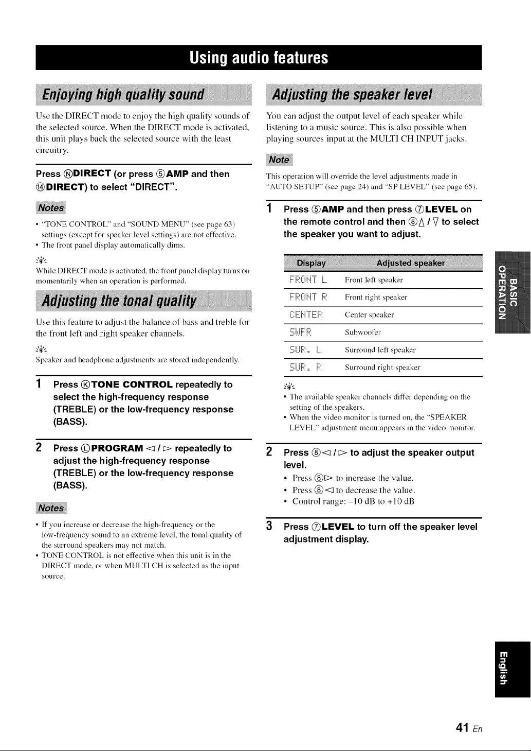
Use the DIRECT mode to enjoy the high quality sounds of
the selected source. When the DIRECT mode is activated,
this unit plays back the selected source with the least
circuitry.
Press @DIRECT (or press @AMP and then
@DIRECT) to select "DIRECT".
• "TONE CONTROL" and "SOUND MENU" (see page 63)
settings (except for speaker level settings) are not effective.
• The fi'ont panel display automatically dims.
_%,._
While DIRECT mode is activated, the front panel display turns on
momentarily when all operation is performed.
Use this feature to adjust the balance of bass and treble for
the front left and right speaker channels.
_%,._
Speaker and headphone adjustments are stored independently.
Press @TONE CONTROL repeatedly to
select the high4requency response
(TREBLE) or the low-frequency response
(BASS).
Press @PROGRAM <1It:> repeatedly to
adjust the high4requency response
(TREBLE) or the low-frequency response
(BASS).
• ff you increase or decrease the high-frequency or the
low-frequency sound to an extreme level, the tonal quality of
the surround speakers may not match.
• TONE CONTROL is not effective when this unit is in the
DIRECT mode, or when MULTI CH is selected as the input
SOtlrce,
You can adjust the output level of each speaker while
listening to a music source. This is also possible when
playing sources input at the MULTI CH INPUT jacks.
This operation will override the level adjustments made in
"AUTO SETUP" (see page 24) and "SP LEVEL" (see page 65).
1 Press @AMP and then press @LEVEL on
the remote control and then @A / V to select
the speaker you want to adjust.
2
3
F:{::;:(){..{TL Front left speaker
F:'{:;?.(.){".{T{:41 Front right speaker
('.i:[:.il{".{"i"[:.ilR Center speaker
'.::,W1"1":'. Subwoofer
'.i:.i;i.i{:;?.= L Surround left speaker
'.i:.i;i.i{:4'.= {:41 Surround right speaker
_%,-_
• The available speaker channels differ depending on the
setting of the speakers.
• When the video monitor is turned on, the "SPEAKER
LEVEL" adjustment menu appears in the video monitor.
Press @<:1 It:> to adjust the speaker output
level.
• Press @t:> to increase the value.
• Press @<:1 to decrease the value.
• Control range:-10 dB to +10 dB
Press @LEVEL to turn off the speaker level
adjustment display.
41 En
The night listening modes are designed to improve
listenability at lower volumes or at night.
2
Press _AMP and then _ NIGHT repeatedly
to select "NIGHT:CINEMA" or
"NIGHT:MUSIC".
Choices: NIGHT:CINEMA, NIGHT:MUSIC, OFF
• Select "NIGHT:CINEMA" when watching films to
reduce the dynamic range of film soundtracks and
make dialog easier to hear at lower volumes.
• Select "NIGHT:MUSIC" when listening to music
sources to preserve ease-of-listening for all sounds.
• Select "OFF" if you do not want to use this feature.
_%,._
When a night listening mode is selected, the NIGHT
indicator lights up ill the front panel display.
Press (_<_ It> to adjust the effect level while
"NIGHT:CINEMA" or "NIGHT:MUSIC" is
displayed in the front panel display.
E.i::.i::,iii=,:::.L.==L.,...,i ii H:[[:,
Choices: MIN, MID, MAX
• Select "MIN" for minimum compression.
• Select "MID" for standard compression.
• Select "MAX" for maximum compression.
_%,._
"NIGHT:CINEMA" and "NIGHT:MUSIC" adjustments are
stored independently.
• You cannot use the night listening modes in the following cases:
-when the DIRECT mode (see page 41 ) is selected.
- when the component connected to the MULTI CH INPUT
jacks is selected as the input source (see page 34).
- when headphones are connected to the PHONES jack.
• The night listening modes may vary in effectiveness depending
on the input source and surround sound settings you use.
42 En
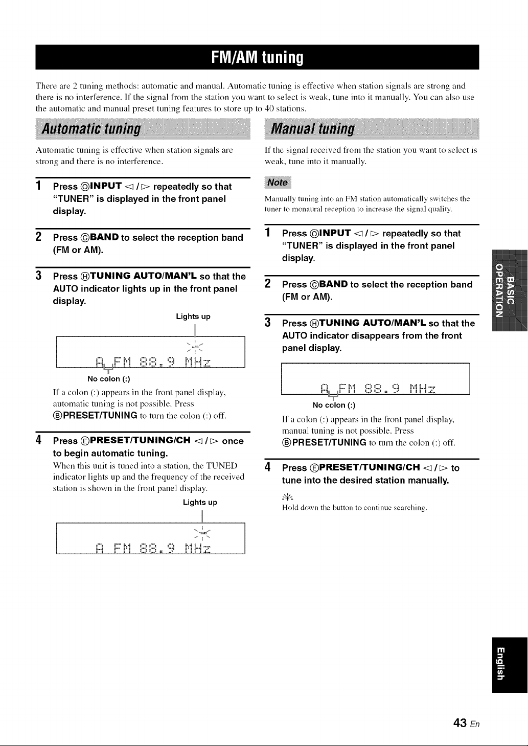
There are 2 tuning methods: automatic and manual. Automatic tuning is effective when station signals are strong and
there is no interference. If the signal from the station you want to select is weak, tune into it manually. You can also use
the automatic and manual preset tuning features to store up to 40 stations.
Automatic tuning is effective when station signals are
strong and there is no interference.
If the signal received from the station you want to select is
weak, tune into it manually.
Press @INPUT <1 It> repeatedly so that
"TUNER" is displayed in the front panel
display.
Manually tuning into an FM station automatically switches the
tuner to monaural reception to increase the signal quality.
Press OBAND to select the reception band
(FM or AM).
Press QTUNING AUTO/MAN'L so that the
AUTO indicator lights up in the front panel
display.
Lights up
..... I ....
No colon(:)
If a colon (:) appears in the front panel display,
automatic tuning is not possible. Press
®PRESET/TUNING to turn the colon (:) oft'.
Press (DPRESET/TUNING/CH <1 / t> once
to begin automatic tuning.
When this unit is tuned into a station, the TUNED
indicator lights up and the frequency of the received
station is shown in the front panel display.
Lights up
2
3
4
Press @INPUT <1/t> repeatedly so that
"TUNER" is displayed in the front panel
display.
Press OBAND to select the reception band
(FM or AM).
Press ®TUNING AUTO/MAN'L so that the
AUTO indicator disappears from the front
panel display.
No colon (:)
If a colon (:) appears in the front panel display,
manual tuning is not possible. Press
®PRESET/TUNING to turn the colon (:) oft'.
Press (DPRESET/TUNING/CH <I / t> to
tune into the desired station manually,
_%,-_
Hold down the button to continue searching.
., (_ ,
al
43 En
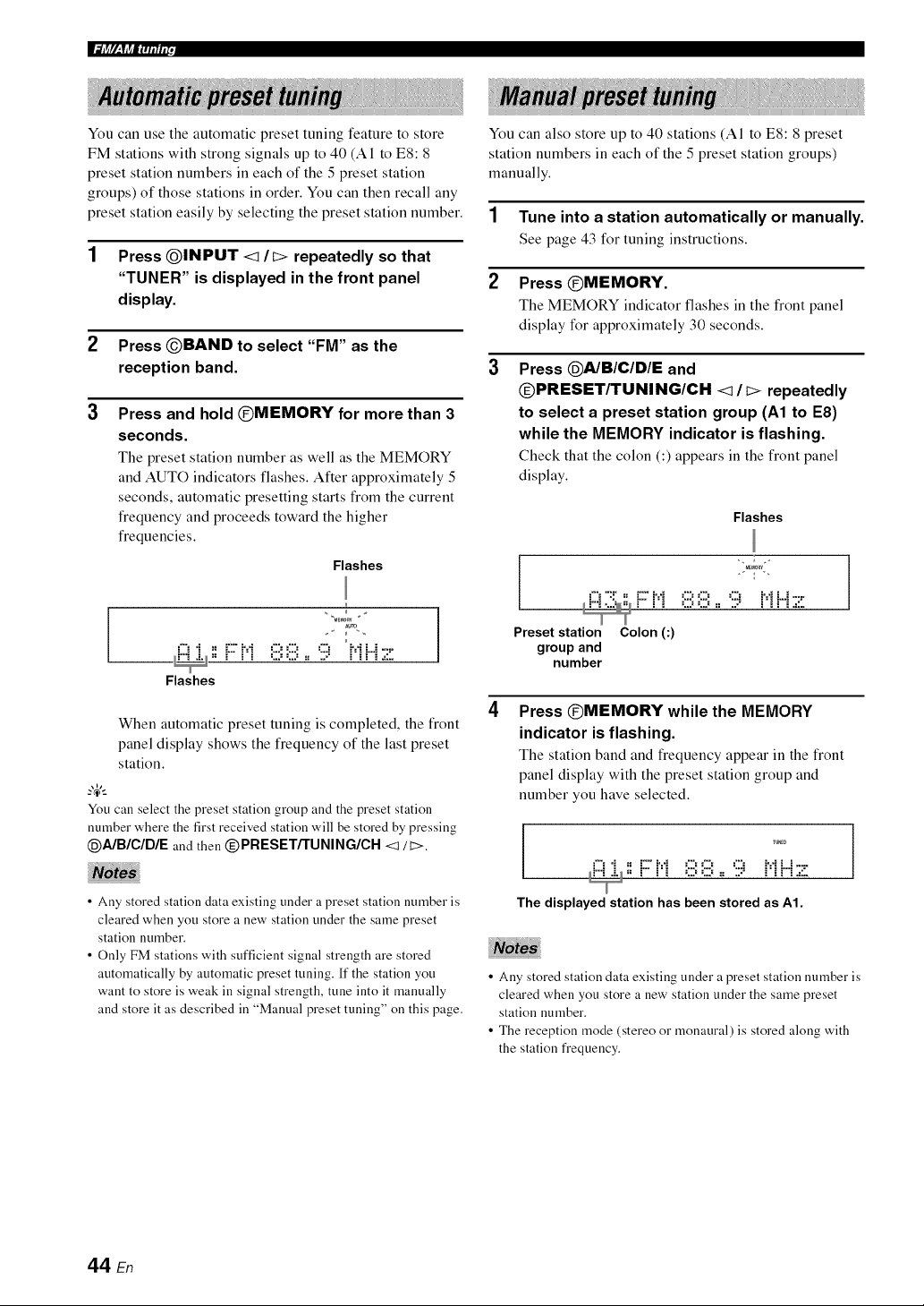
You can use the automatic preset tuning feature to store
FM stations with strong signals up to 40 (A1 to ES: 8
preset station numbers in each of the 5 preset station
groups) of those stations in order. You can then recall any
preset station easily by selecting the preset station number.
1 Press QINPUT <1/i> repeatedly so that
"TUNER" is displayed in the front panel
display.
2 Press @BAND to select "FM" as the
reception band.
3
Press and hold @MEMORY for more than 3
seconds.
The preset station number as well as the MEMORY
and AUTO indicators flashes. After approximately 5
seconds, automatic presetting starts from the current
frequency and proceeds toward the higher
frequencies.
Flashes
Aura
L..," i 2 D- m= ," :.,,: :.,.: ..,a m=," .".--,""::"
--. - = = =, .., ..,., .,= .., = =, = =, ,===
Flashes
When automatic preset tuning is completed, the front
panel display shows the frequency of the last preset
station.
You can select the preset station group and the preset station
number where the first received station will be stored by pressing
@A/B/C/DIE and then @PRESETf'FUNING/CH <1/ t>.
• Ally stored station data existing under a preset station number is
cleared when you store a new station under the same preset
station number.
• Only FM stations with sufficient signal strength are stored
automatically by automatic preset tuning. If the station you
want to store is weak in signal strength, tune into it manually
and store it as described in "Manual preset tuning" on this page.
You can also store up to 40 stations (AI to ES: 8 preset
station numbers in each of the 5 preset station groups)
manually.
1 Tune into a station automatically or manually.
See page 43 for tuning instructions.
2 Press @MEMORY.
The MEMORY indicator flashes in the front panel
display for approximately 30 seconds.
Press @AIBIClDIE and
@PRESETFIFUNING/CH <1/c> repeatedly
to select a preset station group (A1 to E8)
while the MEMORY indicator is flashing.
Check that the colon (:) appears in the front panel
display.
Flashes
r i_ o o := :;:; i_ ri .=::.
Preset station Colon (:)
groupand
number
]
Press @MEMORY while the MEMORY
indicator is flashing.
The station band and frequency appear in the front
panel display with the preset station group and
number you have selected.
='% "i _= r" i,. a. ¢% ¢% ¢% i,. a. i =......
_i"'_ .i._,, r" ['i OO := :;:; ['_r"_.=:;.
The displayed station has been stored as A1.
• Any stored station data existing under a preset station number is
cleared when you store a new station under the same preset
station number.
• The reception mode (stereo or monaural) is stored along with
the station frequency.
44 En
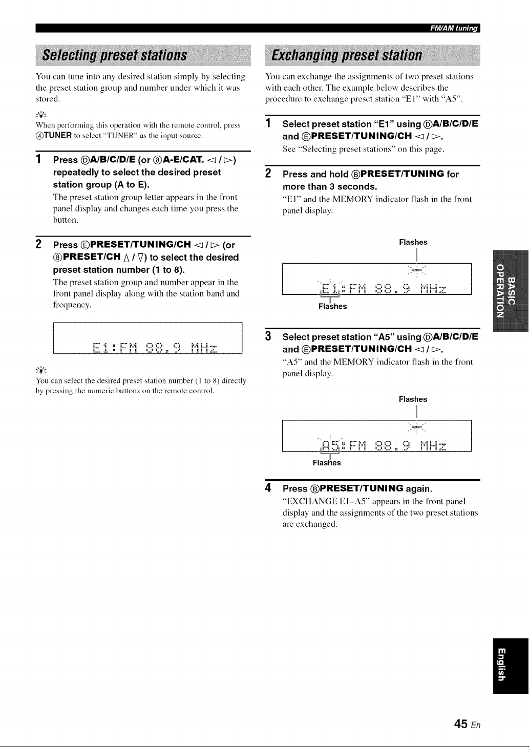
You can tune into any desired station simply by selecting
the preset station group and number under which it was
stored.
When performing this operation with the remote control, press
@TUNER to select "TUNER" as the input source.
Press @A/B/C/DIE (or @A-E/CAT. <1 /C>)
repeatedly to select the desired preset
station group (A to E).
The preset station group letter appears in the front
panel display and changes each time you press the
button.
Press @PRESET/TUNING/CH <1/I> (or
@PRESET/CH A / V) to select the desired
preset station number (1 to 8).
The preset station group and number appear in the
front panel display along with the station band and
frequency.
I i:::"'i _ i:::"M _:::__:::_ ':::i M i.4-::"
You can select the desired preset station number (1 to 8) directly
by pressing the numeric buttons on the remote control.
You can exchange the assignments of two preset stations
with each other. The example below describes the
procedure to exchange preset station "El" with "AS".
1 Select preset station "El" using @A/BIClDIE
and @PRESET/TUNING/CH <1 / _>.
See "Selecting preset stations" on this page.
2
Press and hold ®PRESET/TUNING for
more than 3 seconds.
"El" and the MEMORY indicator flash in the front
panel display.
Flashes
3
Select preset station "A5" using @A/BIClDIE
and @PRESET/TUNING/CH <1 / _>.
"A5" and the MEMORY indicator flash in the front
panel display.
Flashes
Fld'"i...._=_ F" _'i ,:::_,:::,:, :::: F_r"i.,::.
4
Press ®PRESET/TUNING again.
"EXCHANGE El-A5" appears in the front panel
display and the assignments of the two preset stations
are exchanged.
45 En
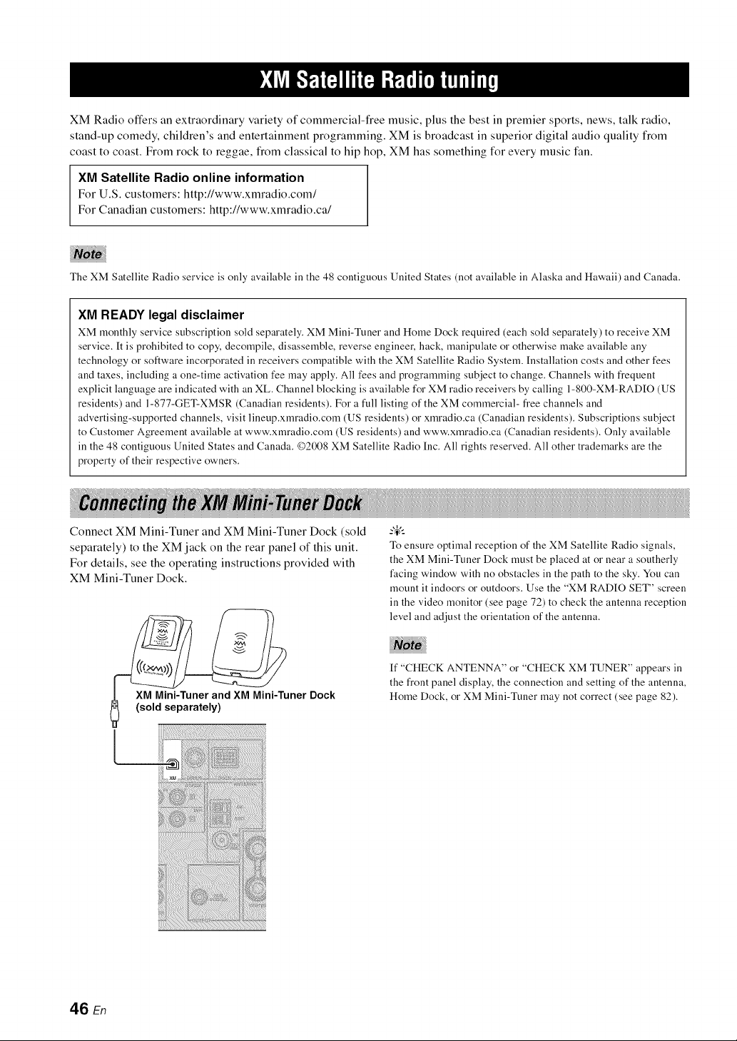
XM Radio offers an extraordinary variety of commercial-free music, plus the best in premier sports, news, talk radio,
stand-up comedy, children's and entertainment programming. XM is broadcast in superior digital audio quality from
coast to coast. From rock to reggae, from classical to hip hop, XM has something for every music fan.
XM Satellite Radio online information
For U.S. customers: http://www.xmradio.com/
For Canadian customers: http://www.xmradio.ca/
The XM Satellite Radio service is only available ill the 48 contiguous United States (not available ill Alaska and Hawaii) and Canada.
XM READY legal disclaimer
XM monthly service subscription sold separately. XM Mini-Tuner and Home Dock required (each sold separately) to receive XM
service. It is prohibited to copy, decompile, disassemble, reverse engineer, hack, manipulate or otherwise make available any
technology or software incorporated in receivers compatible with the XM Satellite Radio System. [nstallation costs and other fees
and taxes, including a one-time activation fee )nay apply. All fees and programming subject to change. Channels with frequent
explicit language are indicated with an XL. Channel blocking is available for XM radio receivers by calling 1-800-XM-RADIO (US
residents) and 1-877-GET-XMSR (Canadian residents). For a hdl listing of the XM commercial- fi'ee channels and
advertising-supported channels, visit lineup.xmradio.com (US residents) or xmradio.ca (Canadian residents). Subscriptions subject
to Customer Agreement available at www.xmradio.com (US residents) and www.xmradio.ca (Canadian residents). Only available
in the 48 contiguous United States and Canada. ©2008 XM Satellite Radio Inc. All rights reserved. All other trademarks are the
property of their respective owners.
Connect XM Mini-Tuner and XM Mini-Tuner Dock (sold
separately) to the XM jack on the rear panel of this unit.
For details, see the operating instructions provided with
XM Mini-Tuner Dock.
XM Mini-Tuner and XM Mini-Tuner Dock
(sold separately)
To ensure optimal reception of the XM Satellite Radio signals,
the XM Mini-Tuner Dock must be placed at or near a southerly
facing window with no obstacles in the path to the sky. You can
mount it indoors or outdoors. Use the "XM RADIO SET" screen
in the video monitor (see page 72) to check the antenna reception
level and adjust the orientation of the antenna.
[f "CHECK ANTENNA" or "CHECK XM TUNER" appears in
the fi'ont panel display, the connection and setting of the antenna,
Home Dock, or XM Mini-Tuner may not correct (see page 82).
46 En
:lirjB.'._FJIllF:'J.'ET;ll'_elamr°
Once you have installed the XM Mini-Tuner Dock,
inserted the XM Mini-Tuner, connected the XM
Mini-Tuner Dock to your XM Ready® home audio
system, and installed the antenna, you are ready to
subscribe and begin receiving XM programming. There
are three places to find your eight character XM Radio ID:
on the XM Mini-Tuner, on the XM Mini-Tuner package,
and on XM Channel 0. Record the Radio ID in the
following eight squares for reference.
r--lr--lr--lr--lr--lr--lr--lr--1
The XM Radio ID does not use the letters 'T', "O", "S" or "F".
Activate your XM Satellite Radio service in the U.S. online at
http:llwww.xmradio.com/or call 1-800-XM-RADIO
(1-800-967-2346). You will need a major credit card. XM will
send a signal from the satellites to activate the full channel lineup.
Activation normally takes 10 to 15 minutes, but during peak busy
periods you may need to keep your XM Ready home audio
system on for up to all hour. When you can access the full channel
lineup on your XM Ready home audio system you are done. For
more information or to subscribe in Canada, visit XM on the Web
at www.xmradio.ca or call XM's Listener Care at
1-877-GET-XMSR (1-877-438-9677).
Press QINPUT <1/c> repeatedly (or press
@XM) to select "XM" as the input source.
The cursor on the left of the XM indicator lights up in
the front panel display and the XM Satellite Radio
information (such as channel number, channel name,
category, artist name, or song title) for the currently
selected channel appears in the front panel display.
Lights up
MUL_e_ DVR V-AUX DTV/CBL DVD M_CD-R CD _En
1
When you select "XM" as the input source, this unit
automatically recalls the previously selected channel.
• The XM Satellite Radio signals cannot be output at the
AUDIO OUT (REC) jacks.
• If a status message or an error message appears in the front
panel display or in the OSD, see the "XM Satellite Radio"
section in "Troubleshooting" on page 78 for appropriate
remedies.
2 Search for a channel by using one of the XM
Satellite Radio search modes.
• To select a channel from the all channel list, see
"All Channel Search mode" on page 48.
• To select a channel by category, see "Category
Search mode" on page 48.
• To select a channel from the preset channels, see
"Preset Search mode" on page 48.
• To select the desired channel directly by entering
the channel number, see "Direct Number Access
mode" on page 48.
-4'--
• You can use the Neural Surround decoder to enjoy the XM HD
surround sound content of the XM Satellite Radio broadcasts in
multi-channels (see page 39).
• You can set the XM Satellite Radio preset channels (see
page 49).
• You can display the XM Satellite Radio information in the front
panel display or in the OSD (see page 50).
47 En
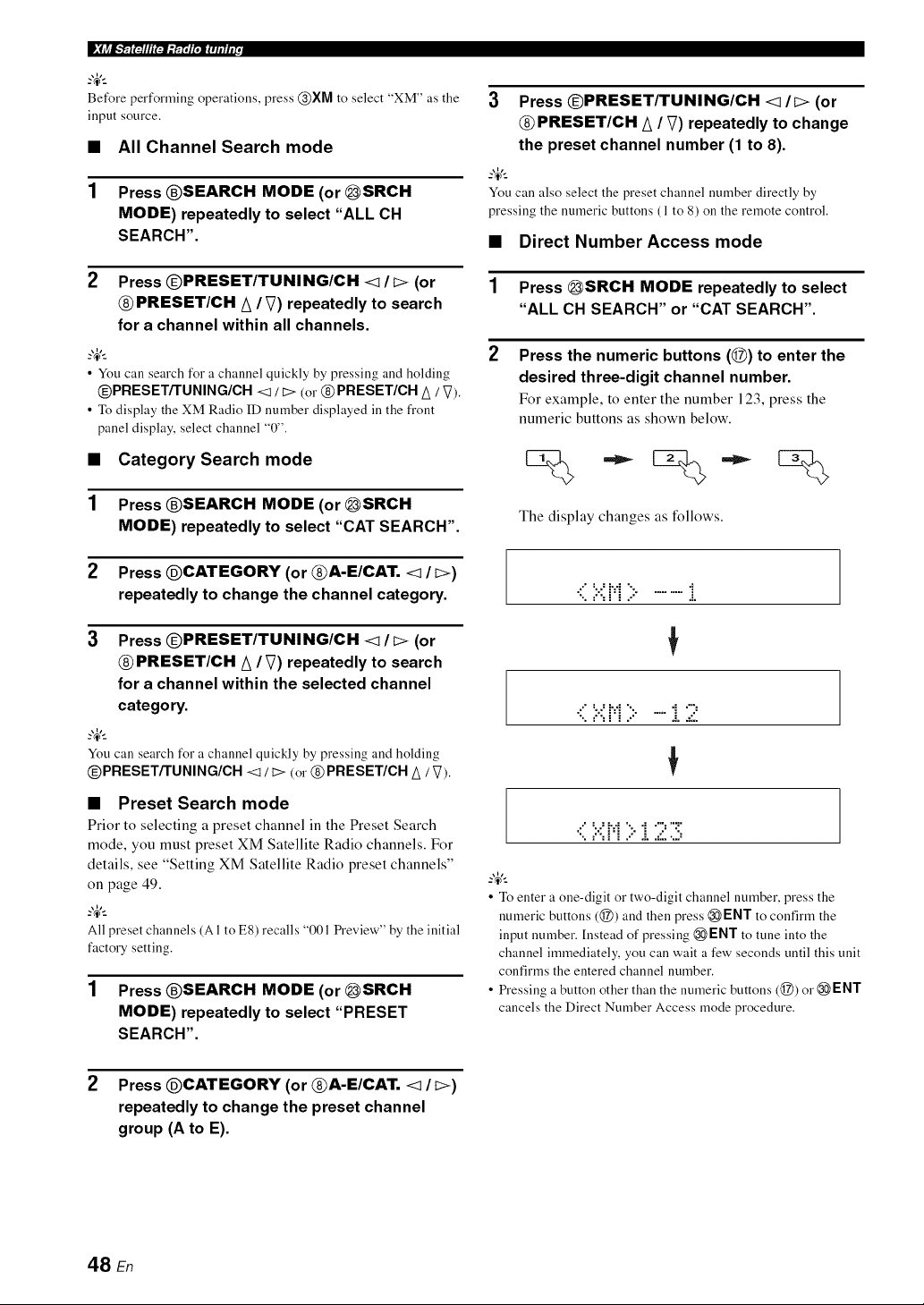
• ,'_-]ll'J_[ J[,ZI Iillii.
Before performing operations, press @XM to select "XM" as the
input source,
• All Channel Search mode
1 Press @SEARCH MODE (or _SRCH
MODE) repeatedly to select "ALL CH
SEARCH".
2 Press @PRESET/TUNING/CH <l/I> (or
@ PRESET/CH A / V) repeatedly to search
for a channel within all channels.
• You can search for a channel quickly by pressing and holding
@PRESETiTUNING/CH <t / I> (or @PRESET/CH A / V).
• To display the XM Radio ID number displayed ill the front
panel display, select channel "0".
• Category Search mode
1 Press @SEARCH MODE (or _SRCH
MODE) repeatedly to select "CAT SEARCH".
2 Press @CATEGORY (or @A-E/CAT. <1 / I>)
repeatedly to change the channel category.
3
Press OPRESET/TUNING/CH <1/t> (or
PRESET/CH A / V) repeatedly to search
for a channel within the selected channel
category,
_o_%_
You can search for a channel quickly by pressing and holding
@PRESETiTUNING/CH <1/ I> (or @PRESET/CH A / V).
• Preset Search mode
Prior to selecting a preset channel in the Preset Search
mode, you must preset XM Satellite Radio channels. For
details, see "Setting XM Satellite Radio preset channels"
on page 49.
_%,._
All preset channels (AI to E8) recalls "001 Preview" by the initial
factory setting.
1 Press @SEARCH MODE (or _SRCH
MODE) repeatedly to select "PRESET
SEARCH",
3 Press @PRESET/TUNING/CH <l/t> (or
PRESET/CH A /V) repeatedly to change
the preset channel number (1 to 8).
_o_%_
You can also select the preset channel number directly by
pressing the numeric buttons ( 1to 8) on the remote control.
• Direct Number Access mode
1 Press _SRCH MODE repeatedly to select
"ALL CH SEARCH" or "CAT SEARCH".
Press the numeric buttons (@) to enter the
desired three-digit channel number.
For example, to enter the number 123, press the
numeric buttons as shown below.
The display changes as follows.
•( 7,i:i;:...........i
•( 7:H;:..... i.2
•::':.:':'.H '::"'i "7'71
• Toenter a one-digit or two-digit channel number, press the
numeric buttons (@) and then press @ ENT to confirm the
input number.Instead of pressing @ENT to tune into the
channel immediately, you can wait a few seconds until this unit
confirms the entered channel number.
• Pressing a button other than the numeric buttons (@) or @ENT
cancels the Direct Number Access mode procedure.
2 Press @CATEGORY (or @A-E/CAT. <1 / t>)
repeatedly to change the preset channel
group (A to E).
48 En
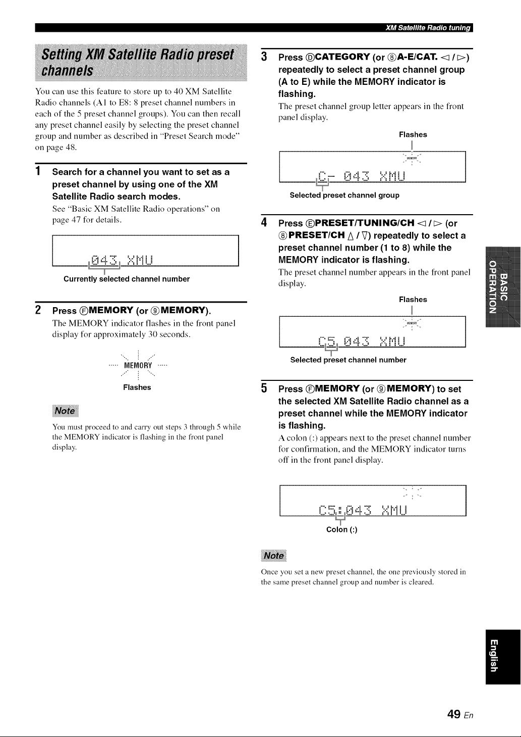
,_lir/_,"_ltJIl'_-l='r_P;l'_lIllllli[,_" , I
You can use this feature to store up to 40 XM Satellite
Radio channels (A1 to E8:8 preset channel numbers in
each of the 5 preset channel groups). You can then recall
any preset channel easily by selecting the preset channel
group and number as described in "Preset Search mode"
on page 48.
Search for a channel you want to set as a
preset channel by using one of the XM
Satellite Radio search modes.
See "Basic XM Satellite Radio operations" on
page 47 for details.
, =.'., _"_ _..E
Currently selected channel number
1
Press @MEMORY (or @MEMORY).
The MEMORY indicator flashes in the front panel
display for approximately 30 seconds.
',, : ..,"
..... MEMORY.....
Flashes
You must proceed to and carry out steps 3 through 5 while
the MEMORY indicator is flashing ill the front panel
display.
3
4
5
Press @CATEGORY (or @A-E/CAT. <1 It>)
repeatedly to select a preset channel group
(A to E) while the MEMORY indicator is
flashing.
The preset channel group letter appears in the front
panel display.
Flashes
Selected preset channel group
J
Press @PRESET/TUNING/CH <1 It:> (or
@ PRESET/CH A / _) repeatedly to select a
preset channel number (1 to 8) while the
MEMORY indicator is flashing,
The preset channel number appears in the front panel
display.
Flashes
J , ,.
_..._ _:_):"_" ..2_ =.'., _"_ _..E
Selected preset channel number
1
Press @MEMORY (or @ MEMORY) to set
the selected XM Satellite Radio channel as a
preset channel while the MEMORY indicator
is flashing.
A colon (:) appears next to the preset channel number
for confirmation, and the MEMORY indicator turns
off in the front panel display.
Colon (:)
Once you set a new preset channel, the one previously stored in
the same preset channel group and number is cleared.
49 En
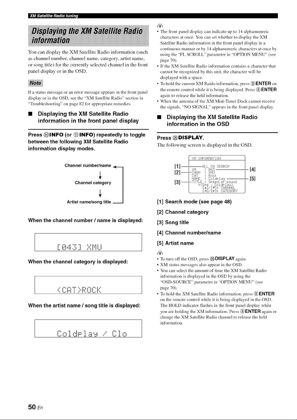
p_jrjlF; " _ e• ;'_-]ll'J_-'_faT i[,zli IilIiE.
You can display the XM Satellite Radio information (such
as channel number, channel name, category, artist name,
or song title) for the currently selected channel in the front
panel display or in the OSD.
If a status message o1"all error message appears in the front panel
display o1"ill the OSD, see the "XM Satellite Radio" section ill
"Troubleshooting" on page 82 for appropriate remedies.
• Displaying the XM Satellite Radio
information in the front panel display
Press (_)INFO (or (_INFO) repeatedly to toggle
between the following XM Satellite Radio
information display modes.
Channel number/name
Channel category
Artist name/song title
When the channel number / name is displayed:
L i::."=..!....?..i ="'=i'i L."
When the channel category is displayed:
When the artist name / song title is displayed:
i""=': "i=".i_:::."i ::::,...-, .." i"""i=':
• .... ,.....:. ,...=, : .:. ,...=, .... • ,...:. ,....
• The front panel display can indicate up to 14 alphanumeric
characters at once. You can set whether to display the XM
Satellite Radio information in the front panel display in a
continuous manner or by 14 alphanumeric characters at once by
using the "FL SCROLL" parameter in "OPTION MENU" (see
page 70).
• If the XM Satellite Radio information contains a character that
cannot be recognized by this unit, the character will be
displayed with a space.
• To hold the current XM Raido information, press @ENTER on
the remote control while it is being displayed. Press @ENTER
again to release the held information.
• When the antenna of the XM Mini-Tuner Dock cannot receive
the signals, "NO SIGNAL" appears in the front panel display.
• Displaying the XM Satellite Radio
information in the OSD
Press _ DISPLAY.
The following screen is displayed in the OSD.
[41
[51
[1] Search mode (see page 48)
[2] Channel category
[3] Song title
[4] Channel number/name
[5] Artist name
• To turn off the OSD, press _DISPLAY again.
• XM status messages also appear in the OSD.
• You can select the amount of time the XM Satellite Radio
information is displayed in the OSD by using the
"OSD-SOURCE" parameter in "OPTION MENU" (see
page 70).
• To hold the XM Satellite Radio information, press @ENTER
on the remote control while it is being displayed in the OSD.
The HOLD indicator flashes in the front panel display while
you are holding the XM information. Press @ENTER again or
change the XM Satellite Radio channel to release the held
information.
50 En
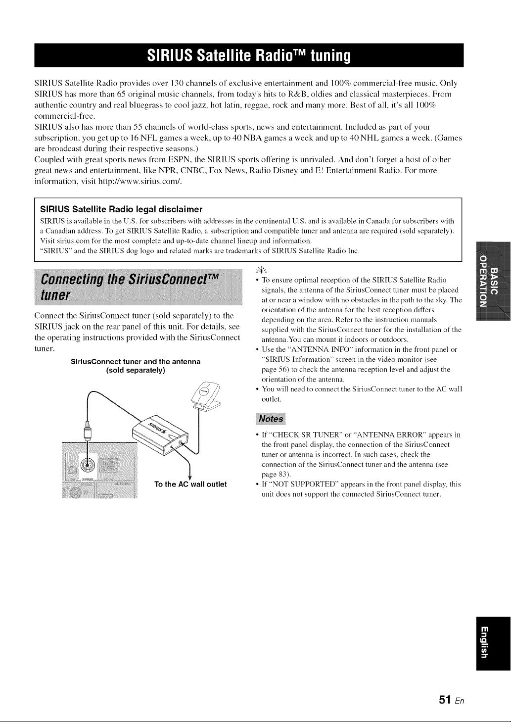
SIRIUS Satellite Radio provides over 130 channels of exclusive entertainment and 100% commercial-free music. Only
SIRIUS has more than 65 original music channels, from today's hits to R&B, oldies and classical masterpieces. From
authentic country and real bluegrass to cool jazz, hot latin, reggae, rock and many more. Best of all, it's all 100%
commercial-free.
SIRIUS also has more than 55 channels of world-class sports, news and entertainment. Included as part of your
subscription, you get up to 16 NFL games a week, up to 40 NBA games a week and up to 40 NHL games a week. (Games
are broadcast during their respective seasons.)
Coupled with great sports news from ESPN, the SIRIUS sports offering is unrivaled. And don't forget a host of other
great news and entertainment, like NPR, CNBC, Fox News, Radio Disney and E! Entertainment Radio. For more
information, visit http://www.sirius.com/.
SIRIUS Satellite Radio legal disclaimer
SIRIUS is available in the U.S. for subscribers with addresses in the continental U.S. and is available in Canada for subscribers with
a Canadian address. To get SIRIUS Satellite Radio, a subscription and compatible tuner and antenna are required (sold separately).
Visit sirius.corn for the most complete and up-to-date channel lineup and information.
"SIRIUS" and the SIRIUS dog logo and related marks are trademarks of SIRIUS Satellite Radio Inc.
Connect the SiriusConnect tuner (sold separately) to the
SIRIUS jack on the rear panel of this unit. For details, see
the operating instructions provided with the SiriusConnect
tuner.
SiriusConnect tuner and the antenna
(sold separately)
• To ensure optimal reception of the SIRIUS Satellite Radio
signals, the antenna of the SiriusConnect tuner must be placed
at or near a window with no obstacles in the path to the sky. The
orientation of the antenna for the best reception differs
depending on the area. Refer to the instruction manuals
supplied with the SiriusConnect tuner for the installation of the
antenna.You can mount it indoors or outdoors.
• Use the "ANTENNA INFO" information in the fi'ont panel or
"SIRIUS Information" screen in the video monitor (see
page 56) to check the antenna reception level and adjust the
orientation of the antenna.
• You will need to connect the SiriusConnect tuner to the AC wall
outlet.
To the AC wall outlet
• ff "CHECK SR TUNER" or "ANTENNA ERROR" appears in
the fi'ont panel display, the connection of the SiriusConnect
tuner or antenna is incorrect. In such cases, check the
connection of the SiriusConnect tuner and the antenna (see
page 83).
• ff "NOT SUPPORTED" appears in the front panel display, this
unit does not support the connected SiriusConnect tuner.
/
51 En
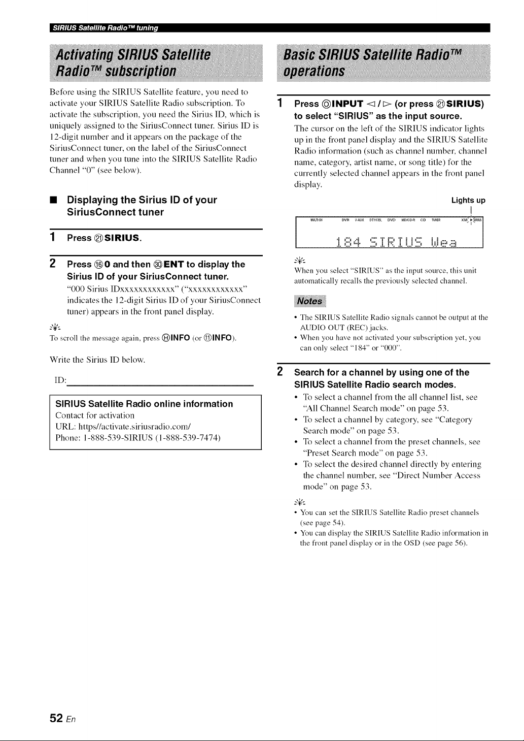
Before using the SIRIUS Satellite feature, you need to
activate your SIRIUS Satellite Radio subscription. To
activate the subscription, you need the Sirius ID, which is
uniquely assigned to the SiriusConnect tuner. Sirius ID is
12-digit number and it appears on the package of the
SiriusConnect tuner, on the label of the SiriusConnect
tuner and when you tune into the SIRIUS Satellite Radio
Channel "0" (see below).
• Displaying the Sirius ID of your
SiriusConnect tuner
1 Press (DSIRIUS.
2 Press (_O and then _ENT to display the
Sirius ID of your SiriusConnect tuner.
"000 Sirius IDxxxxxxxxxxxx" ("xxxxxxxxxxxx"
indicates the 12-digit Sirius ID of your SiriusConnect
tuner) appears in the front panel display.
-4'--
To scroll the message again, press (}J)INFO(or (_)INFO).
Write the Sirius ID below.
ID:
SIRIUS Satellite Radio online information
Contact for activation
URL: httpsl/activate.siriusradio.com/
Phone: 1-888-539-SIRIUS (1-888-539-7474)
Press @INPUT </I:> (or press (@SIRIUS)
to select "SIRIUS" as the input source.
The cursor on the left of the SIRIUS indicator lights
up in the front panel display and the SIRIUS Satellite
Radio information (such as channel number, channel
name, category, artist name, or song title) for the
currently selected channel appears in the front panel
display.
Lights up
DVR V-AU× DTWCBLDVD MOIC_R CD TU_E_ XM_
l
i =iii:,4 :iii:ZF;;:.Zi..i:iii: i.,j,_i,.ii_
When you select "SIRIUS" as the input source, this unit
automatically recalls the previously selected channel.
• The SIRIUS Satellite Radio signals cannot be output at the
AUDIO OUT (REC) jacks.
• When you have not activated your subscription yet, you
can only select "184" or "000",
Search for a channel by using one of the
SIRIUS Satellite Radio search modes.
• To select a channel from the all channel list, see
"All Channel Search mode" on page 53.
• To select a channel by category, see "Category
Search mode" on page 53.
• To select a channel from the preset channels, see
"Preset Search mode" on page 53.
• To select the desired channel directly by entering
the channel number, see "Direct Number Access
mode" on page 53.
-4'--
• You can set the SIRIUS Satellite Radio preset channels
(see page 54).
• You can display the SIRIUS Satellite Radio information in
the front panel display or in the OSD (see page 56).
52 En
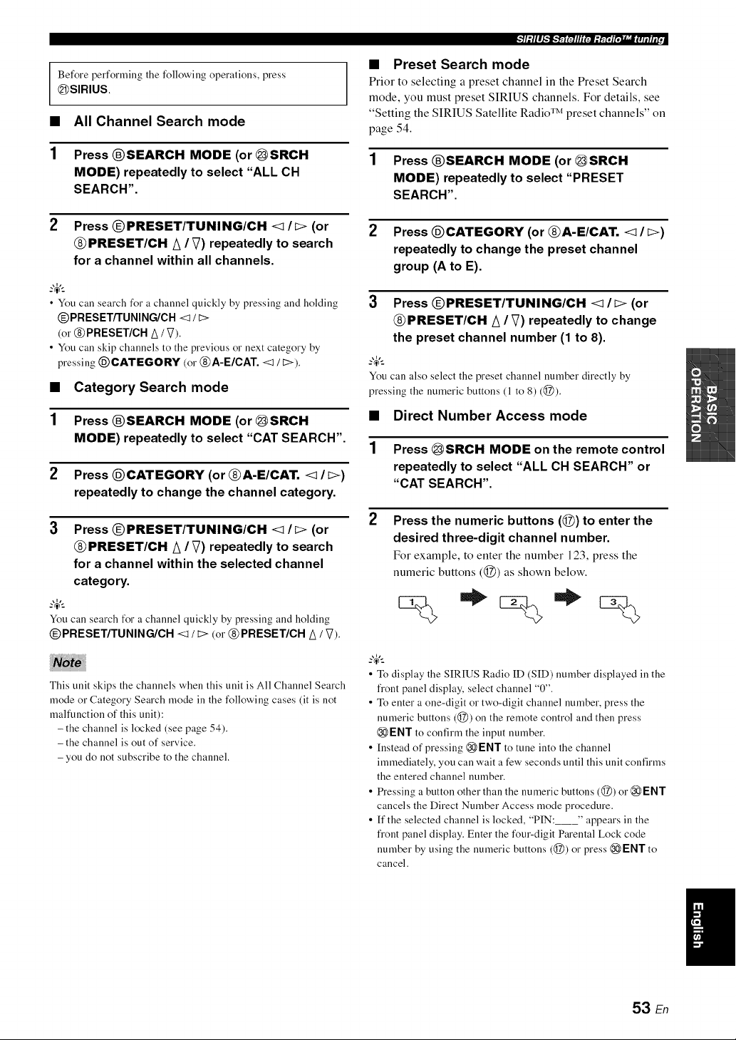
Before performing the followingoperations, press
_SIRIUS.
• All Channel Search mode
1 Press ®SEARCH MODE (or _SRCH
MODE) repeatedly to select "ALL CH
SEARCH".
2 Press @PRESET/TUNING/CH <lit> (or
@ PRESET/CH A / V) repeatedly to search
for a channel within all channels.
• You can search for a channel quickly by pressing and holding
@PRESET/TUNING/CH< / E>
(or @PRESET/CH A/ V).
• You call skip channels to the previous or next category by
pressing @CATEGORY (or @A-E/CAT. <1/ t>).
• Category Search mode
1 Press ®SEARCH MODE (or _SRCH
MODE) repeatedly to select "CAT SEARCH".
2 Press @CATEGORY (or @A-E/CAT. <1 / I>)
repeatedly to change the channel category.
Press @PRESET/TUNING/CH <1 It> (or
@ PRESET/CH A / V) repeatedly to search
for a channel within the selected channel
category.
?_t_
You can search for a channel quickly by pressing and holding
@PRESET/TUNING/CH <1 / D (or @PRESET/CH A / V).
This unit skips the channels when this unit is All Channel Search
mode or Category Search mode in the following cases (it is not
malfunction of this unit):
- the channel is locked (see page 54).
- the channel is out of service.
- you do not subscribe to the channel.
_]l: l l ll_']_'r_ t':Jllll rgll g r'TT_li'gMaJ l_Tit h,t ,
• Preset Search mode
Prior to selecting a preset channel in the Preset Search
mode, you must preset SIRIUS channels. For details, see
"Setting the SIRIUS Satellite Radio TM preset channels" on
page 54.
1 Press ®SEARCH MODE (or _SRCH
MODE) repeatedly to select "PRESET
SEARCH".
2 Press @CATEGORY (or @A-E/CAT. <1 / I>)
repeatedly to change the preset channel
group (A to E).
3 Press @PRESET/TUNING/CH <1/I> (or
@PRESET/CH A / V) repeatedly to change
the preset channel number (1 to 8).
?_t_
You can also select the preset channel number directly by
pressing the numeric buttons (1 to 8) (@).
• Direct Number Access mode
1 Press _SRCH MODE on the remote control
repeatedly to select "ALL CH SEARCH" or
"CAT SEARCH".
2
Press the numeric buttons (@) to enter the
desired three-digit channel number.
For example, to enter the number 123, press the
numeric buttons (@) as shown below.
%*:%*%
• To display the SIRIUS Radio ID (SID) number displayed inthe
front panel display, select channel "0".
• To enter a one-digit or two-digit channel number,press the
numeric buttons (@) on the remote control and then press
ENT to confirm the input number.
• Instead of pressing @ENT to tune into the channel
immediately, you canwait a few secondsuntil this unit confirms
the entered channel number.
• Pressing a button other than the numeric buttons (@) or @ENT
cancels the Direct Number Access mode procedure.
• If the selected channel is locked, "PIN: " appears in the
front panel display.Enter the four-digit Parental Lock code
number by using the numeric buttons (@) or press _ ENT to
cancel.
53 En
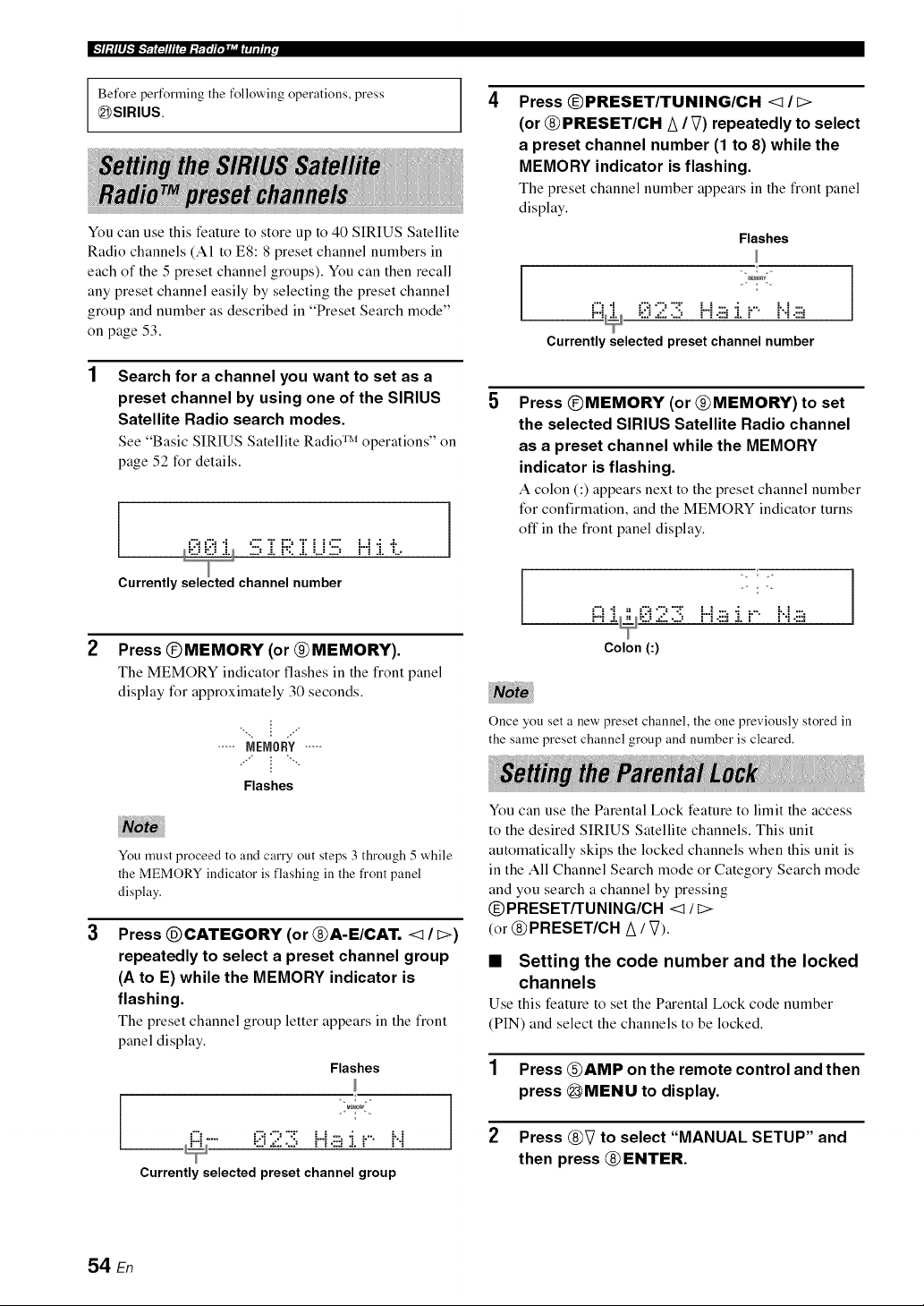
Before performing the following operations, press
_SIRIUS.
You can use this feature to store up to 40 SIRIUS Satellite
Radio channels (A1 to E8:8 preset channel numbers in
each of the 5 preset channel groups). You can then recall
any preset channel easily by selecting the preset channel
group and number as described in "Preset Search mode"
on page 53.
Search for a channel you want to set as a
preset channel by using one of the SIRIUS
Satellite Radio search modes,
See "Basic SIRIUS Satellite Radio TM operations" on
page 52 for details.
::J ::J J-L .--: J, _'.. J, :,J .--: = : a. ,.,,
Currently channel number
2
Press @MEMORY (or @MEMORY),
The MEMORY indicator flashes in the front panel
display for approximately 30 seconds.
..... NENORY.....
Flashes
3
You must proceed to and carry out steps 3 through 5 while
the MEMORY indicator is flashing in the fi'ont panel
display.
Press @CATEGORY (or @A-E/CAT. <1/ I>)
repeatedly to select a preset channel group
(A to E) while the MEMORY indicator is
flashing.
The preset channel group letter appears in the front
panel display.
Flashes
"-..... 0 2 3 Ha :i..... i..i
i
Currently selected preset channel group
Press @PRESET/TUNING/CH <1 /
(or @ PRESET/CH A / V) repeatedly to select
a preset channel number (1 to 8) while the
MEMORY indicator is flashing,
The preset channel number appears in the front panel
display.
Flashes
iZi "i iZ::i9 "Z i-.-i:::,"i i-"- H :::,
= :_ '=." .,,....=,, = : .,.,._ =... = = : .=,_,
Currently selected preset channel number
Press @MEMORY (or @MEMORY) to set
the selected SIRIUS Satellite Radio channel
as a preset channel while the MEMORY
indicator is flashing,
A colon (:) appears next to the preset channel number
for confirmation, and the MEMORY indicator turns
oft"in the front panel display.
/
i:::i 2 :i!!:H J.i.... i..i ]
Colon (:)
Once you set a new preset channel, the one previously stored in
the same preset channel group and number is cleared.
You can use the Parental Lock feature to limit the access
to the desired SIRIUS Satellite channels. This unit
automatically skips the locked channels when this unit is
in the All Channel Search mode or Category Search mode
and you search a channel by pressing
@PRESET/TUNING/CH <_ / _>
(or @PRESET/CH A / V).
• Setting the code number and the locked
channels
Use this feature to set the Parental Lock code number
(PIN) and select the channels to be locked.
1 Press @AMP on the remote control and then
press @MENU to display.
2 Press @V to select "MANUAL SETUP" and
then press @ ENTER.
54 En
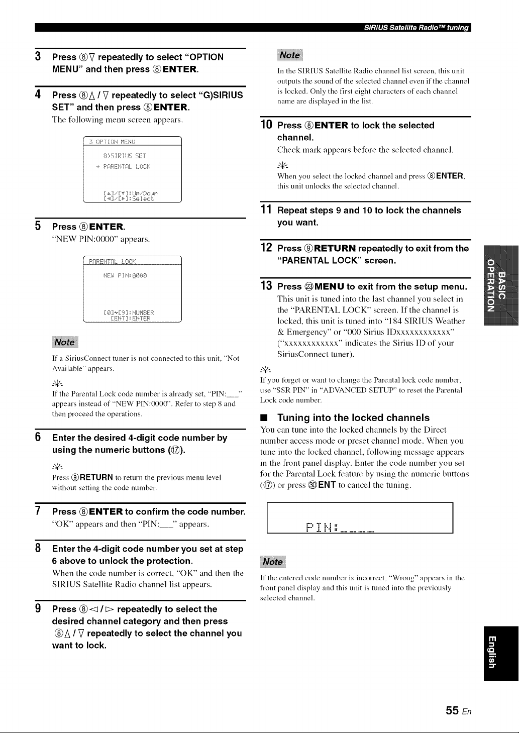
_I ."I I I ._'_J_'_F'31nEEE."{IT_R;',,g_J_3TEIl i r,
Press @V repeatedly to select "OPTION
MENU" and then press @ENTER.
Press @/\ / V repeatedly to select "G)SIRIUS
SET" and then press @ENTER.
The following menu screen appears.
:?; OPTION }}ENI..I
_:]i;,:[;! R! IJ!!7f;ET
._, P;:IREH72t. I..00:::
[ ._,[i.-'[v' ] :;I..ll=_-. !3,::,a_,,
[.4] .- [_ ] _":!i;e1.ec'i:.
Press @ ENTER.
"NEW PIN:0000" appears.
[ _.?:i_ [9 ] :rI".ll.._l%:!!i:R
ff a SiriusConnect tuner is not connected to this unit, "Not
Available" appears.
_.,_,._
ff the Parental Lock code number is already set, "PIN:_"
appears instead of "NEW PIN:0000". Refer to step 8 and
then proceed the operations.
Enter the desired 4-digit code number by
using the numeric buttons (@).
Press @ RETURN to return the previous menu level
without setting the code number.
Press @ENTER to confirm the code number.
"OK" appears and then "PIN: " appears.
Enter the 4-digit code number you set at step
6 above to unlock the protection.
When the code number is correct, "OK" and then the
SIRIUS Satellite Radio channel list appears.
Press @<1 / _ repeatedly to select the
desired channel category and then press
@/\ / V repeatedly to select the channel you
want to lock.
10
In the SIRIUS Satellite Radio channel list screen, this unit
outputs the sound of the selected channel even if the channel
is locked. Only the first eight characters of each channel
name are displayed in the list.
Press @ENTER to lock the selected
channel.
Check mark appears before the selected channel.
_.,_,._
When you select the locked channel and press @ ENTER,
this unit unlocks the selected channel.
11 Repeat steps 9 and 10 to Iockthe channels
you want.
12 Press @RETURN repeatedly to exit from the
"PARENTAL LOCK" screen.
13 Press @MENU to exit from the setup menu.
This unit is tuned into the last channel you select in
the "PARENTAL LOCK" screen. If the channel is
locked, this unit is tuned into "184 SIRIUS Weather
& Emergency" or "000 Sirius IDxxxxxxxxxxxx"
("xxxxxxxxxxxx" indicates the Sirius ID of your
SiriusConnect tuner).
_.,_,._
If you forgetor want to change the Parental lock code number,
use "SSR PIN" in "ADVANCEDSETUP" to reset the Parental
Lock code number.
• Tuning into the locked channels
You can tune into the locked channels by the Direct
number access mode or preset channel mode. When you
tune into the locked channel, following message appears
in the front panel display. Enter the code number you set
for the Parental Lock feature by using the numeric buttons
(@) or press @ ENT to cancel the tuning.
i::::T i'..i;',
If the entered code number is incorrect, "Wrong" appears in the
front panel display and this unit is tuned into the previously
selected channel.
55 En
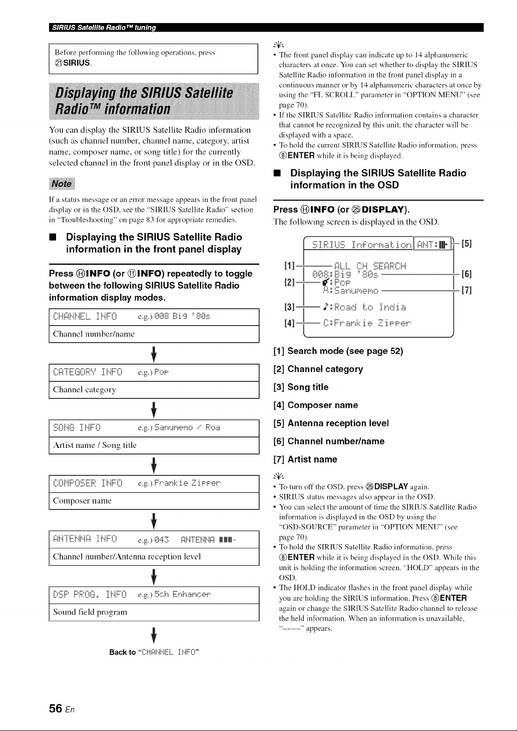
Before performing the following operations, press
_SIRIUS.
You can display the SIRIUS Satellite Radio information
(such as channel number, channel name, category, artist
name, composer name, or song title) for the currently
selected channel in the front panel display or in the OSD.
If a status message o1"an error message appears in the front panel
display o1"in the OSD, see the "SIRIUS Satellite Radio" section
in "Troubleshooting" on page 83 for appropriate remedies.
• Displaying the SIRIUS Satellite Radio
information in the front panel display
Press @INFO (or @INFO) repeatedly to toggle
between the following SIRIUS Satellite Radio
information display modes.
i2{{Ab{b{[iilL,lib{{:::() e.g.)00',i?,ii?,:i.';i:'',i?,0:....
Channel number/name
(ii:{:::{i[:ili)ii(){:;;:Y][{..{{:::(.ii e.g.) F::',:::,r
Channel category
:i:2;Oi".ii?2ii2i".ii:::0 e.g.):iii;._,nur.,er.,,:::......F;;:,...,.:::,
Artist name / Song title
i2()Mi:::'i3:iii;iiii]:;:i i".{i:::0 e.g.)F:'i"'.!!!,i"_i:::i.e ;;!::i.F::F::ei....
Compose]" name
{:)N"i"[:.ii{".{{".{{:)][{".{{:::'('.ii e.g.) 0,::i.11:.[;i:::ii".i"i=Eii".ii".ii:::iIIIIIIIIIIIII.....
Channel number/Antenna reception level
{
[;,:i:2;i:::'i:::'i::;:0(:2i==ii".ii:::0 e.g.)!=.:.k:.i",E:ni,.:::,,,,....,:::.,
Sound field program
Back to "(?lil:::li"ii"iEL. i I".iF::O"
• The front panel display can indicate up to 14 alphanumeric
characters at once. You can set whether to display the SIRIUS
Satellite Radio information in the front panel display in a
continuous manner or by 14 alphanumeric characters at once by
using the "FL SCROLL" parameter in "OPTION MENU" (see
page 70).
• If the SIRIUS Satellite Radio information contains a character
that cannot be recognized by this unit, the character will be
displayed with a space.
• To hold the current SIRIUS Satellite Radio information, press
@ENTER while it is being displayed.
• Displaying the SIRIUS Satellite Radio
information in the OSD
Press @INFO (or _ DISPLAY).
The following screen is displayed in the OSD.
[51
[61
[71
[1] Search mode (see page 52)
[2] Channel category
[3] Song title
[4] Composer name
[5] Antenna reception level
[6] Channel number/name
[7] Artist name
• To turn off the OSD, press _DISPLAY again.
• SIRIUS status messages also appear in the OSD.
• You can select the amount of time the SIRIUS Satellite Radio
information is displayed in the OSD by using the
"OSD-SOURCE" parameter in "OPTION MENU" (see
page 70).
• To hold the SIRIUS Satellite Radio information, press
@ENTER while it is being displayed in the OSD. While this
unit is holding the information screen, "HOLD" appears in the
OSD.
• The HOLD indicator flashes in the front panel display while
you are holding the SIRIUS information. Press @ ENTER
again or change the SIRIUS Satellite Radio channel to release
the held information. When an information is unavailable,
" appears.
56 En
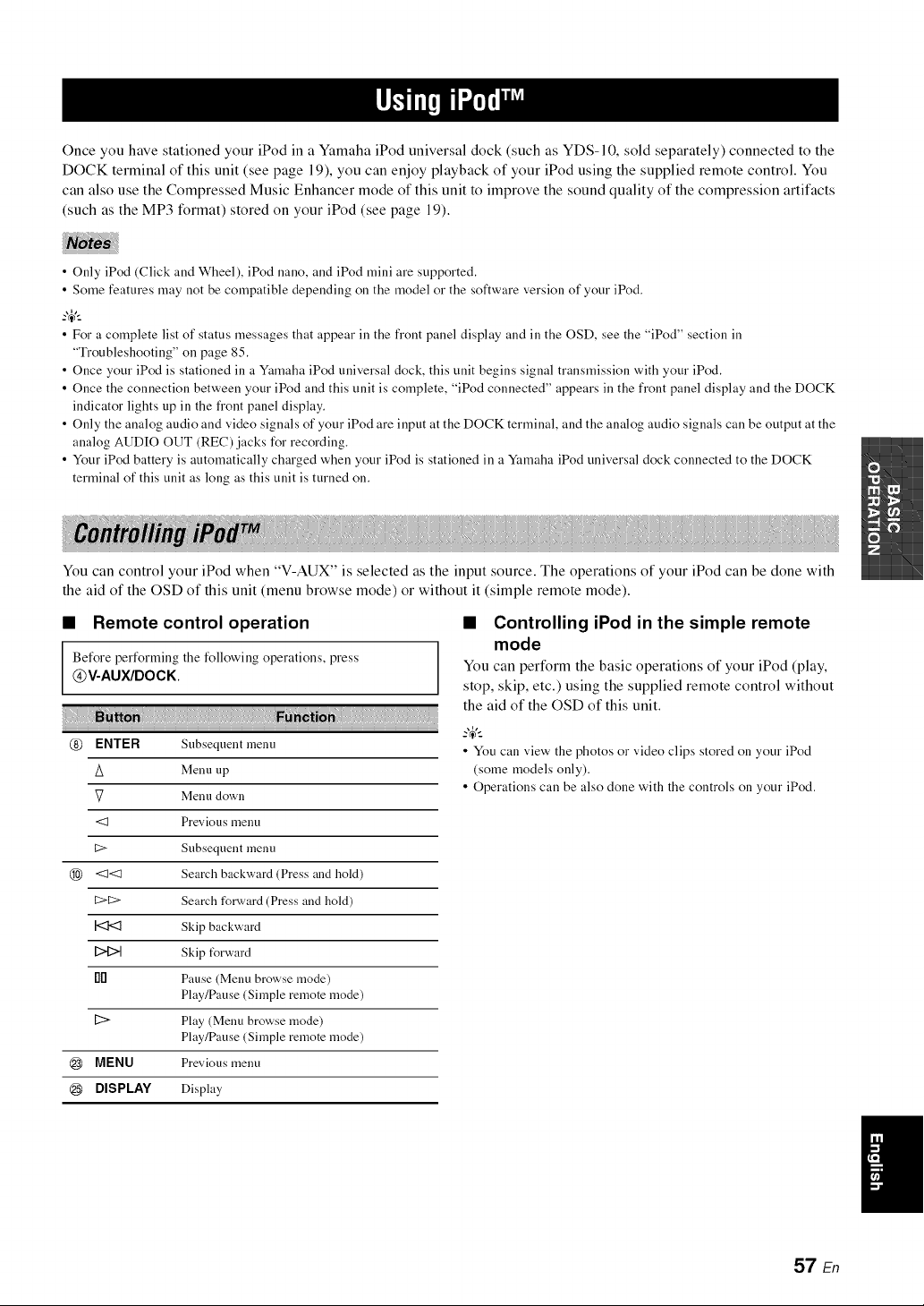
Once you have stationed your iPod in a Yamaha iPod universal dock (such as YDS-10, sold separately) connected to the
DOCK terminal of this unit (see page 19), you can enjoy playback of your iPod using the supplied remote control. You
can also use the Compressed Music Enhancer mode of this unit to improve the sound quality of the compression artifacts
(such as the MP3 format) stored on your iPod (see page 19).
• Only iPod (Click and Wheel), iPod nano, and iPod mini are supported.
• Some features may not be compatible depending on the model or the software version of your iPod.
--'4'--
• For a complete list of status messages that appear ill the front panel display and ill the OSD, see the "iPod" section ill
"Troubleshooting" on page 85.
• Once your iPod is stationed in a Ymnaha iPod universal dock, this unit begins signal transmission with your iPod.
• Once the connection between your iPod and this unit is complete, "iPod connected" appears in the front panel display and the DOCK
indicator lights up in the front panel display.
• Only the analog audio and video signals of your iPod are input at the DOCK terminal, and the analog audio signals can be output at the
analog AUDIO OUT (REC)jacks for recording.
• Your iPod battery is automatically charged when your iPod is stationed in a Ymnaha iPod universal dock connected to the DOCK
terminal of this unit as long as this unit is turned on.
You can control your iPod when "V-AUX" is selected as the input source. The operations of your iPod can be done with
the aid of the OSD of this unit (menu browse mode) or without it (simple remote mode).
• Remote control operation
Before performing the following operations, press
@V-AUX/DOCK
@ ENTER Subsequent menu
A Menu up
V Menu down
<1 Previous menu
C> Subsequent menu
@ <1<1 Search backward (Press and hold)
C>C> Search forward (Press and hold)
I<I<t Skip backward
DID Skip t_rward
fl[] Pause (Menu browse mode)
Play/Pause (Simple remote mode)
[2> Play (Menu browse mode)
Play/Pause (Simple remote mode)
@ MENU Previous menu
@ DISPLAY Display
• Controlling iPod in the simple remote
mode
You can perform the basic operations of your iPod (play,
stop, skip, etc.) using the supplied remote control without
the aid of the OSD of this unit.
• You can view the photos or video clips stored on your iPod
(some models only).
• Operations can be also done with the controls on your iPod.
57 En
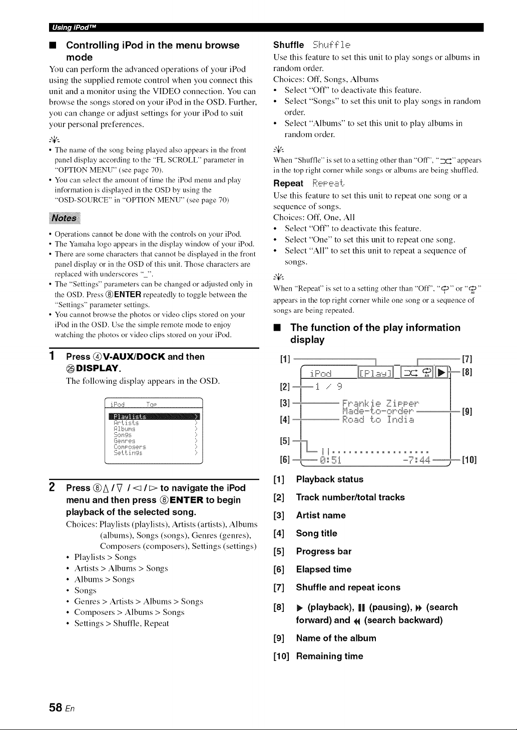
ll_,,_Wlii_lll'
• Controlling iPod in the menu browse
mode
You can perform the advanced operations of your iPod
using the supplied remote control when you connect this
unit and a monitor using the VIDEO connection. You can
browse the songs stored on your iPod in the OSD. Further,
you can change or adjust settings for your iPod to suit
your personal preferences.
-4'--
• The name of the song being played also appears ill the front
panel display according to the "FL SCROLL" parameter ill
"OPTION MENU" (see page 70).
• You call select the amount of time the iPod menu and play
information is displayed ill the OSD by using the
"OSD-SOURCE" ill "OPTION MENU" (see page 70)
• Operations cannot be done with the controls on your iPod.
• The Yamaha logo appears in the display window of your iPod,
• There are some characters that cannot be displayed in the front
panel display or in the OSD of this unit. Those characters are
replaced with underscores "_",
• The "Settings" parameters can be changed or adjusted only in
the OSD. Press @ENTER repeatedly to toggle between the
"Settings" parameter settings.
• You cannot browse the photos or video clips stored on your
iPod in the OSD, Use the simple remote )node to enjoy
watching the photos or video clips stored on your iPod,
1 Press @V-AUX/DOCK and then
@mSPLAY.
The following display appears in the OSD.
iP<:,d Tol;:
A<i. i:_ i.s ;;
I]:_el"*l" e:ii [:;
I[h3rq F o:il J_?v':_i )
ii{e i:. i:.:i.f_g:_i )-
2
Press @A / _7 / <1 / t> to navigate the iPod
menu and then press @ENTER to begin
playback of the selected song.
Choices: Playlists (playlists), Artists (artists), Albums
(albums), Songs (songs), Genres (genres),
Composers (composers), Settings (settings)
• Playlists > Songs
• Artists > Albums > Songs
• Albums > Songs
• Songs
• Genres > Artists > Albums > Songs
• Composers > Albums > Songs
• Settings > Shuffle, Repeat
Shuffle :iii;huF"F],e
Use this feature to set this unit to play songs or albums in
random order.
Choices: Oft', Songs, Albums
• Select "Oft" to deactivate this feature.
• Select "Songs" to set this unit to play songs in random
order.
• Select "Albums" to set this unit to play albums in
random order.
When "Shuffle" is setto a setting other than "Off", "__F'_"appears
in the top right corner while songs or albums are being shuftqed,
Repeat i:;;:e!:::,e.!!!ri:,
Use this feature to set this unit to repeat one song or a
sequence of songs.
Choices: Oft', One, All
• Select "Oft" to deactivate this feature.
• Select "One" to set this unit to repeat one song.
• Select "All" to set this unit to repeat a sequence of
songs.
-4'--
When "Repeat" is set to a setting other than "Off', "_10"or "_"
appears in the top right corner while one song or a sequence of
songs are being repeated.
• The function of the play information
display
111 _ 171
- 181
121 [ .... .., -
Nl Road t.o Ind:i.a
I51[L
[1] Playback status
[2] Track number/total tracks
[3] Artist name
[4] Song title
[5] Progress bar
[6] Elapsed time
[7] Shuffle and repeat icons
[8] b (playback), I| (pausing), t_ (search
forward) and 14 (search backward)
[9] Name of the album
[10] Remaining time
58 En
You can connect a Yamaha Bluetooth adapter (such as YBA-10, sold separately) to the DOCK terminal of this unit and
enjoy the music contents stored in your Bluetooth component (such as a portable music player) without wiring between
this unit and the Bluetooth component. You need to perform "pairing" the connected Bluetooth adapter and your
Bluetooth component in advance.
Pairing must be performed when using a Bluetooth
component with the Bluetooth adapter connected to this
unit for the first time or if the pairing data has been 4
deleted. "Pairing" refers to the operation of registering a
Bluetooth component for Bluetooth communications.
-4'--
• You only need the pairing operation for the first time that you
use the Bluetooth component with the Bluetooth adapter.
• Pairing requires operations on this unit and on the other 5
component with which Bluetooth communications are to be
established. If necessary,refer to the other component's
operating instructions.
There are two pairing methods: pairing by using "START
PAIRING" in "SET MENU" and quick pairing.
• Pairing by using "SET MENU"
Use this feature to perform pairing with the video monitor.
Select "START PAIRING" in "INPUT MENU". See
page 71 for details.
• Quick pairing
To ensure security, a time limit of 8 minutes is set for the
pairing operation. You are recommended to read and fully
understand all the instructions before starting.
1 Press @INPUT <:1It> repeatedly (or press
@V-AUX/DOCK) to select "V-AUX" as the
input source,
2 Turn on the Bluetooth component you want
to pair with,
3 Press and hold @BAND (or (2)BAND) for 3
seconds to start pairing.
Once the Bluetooth adapter starts pairing,
"Searching..." appears for a moment. While the
Bluetooth adapter is in the pairing mode, DOCK
indicator flashes in the front panel display.
-4'--
To cancel the pairing, press @BAND (or @BAND) again.
If the Bluetooth adapter is not connected to the DOCK
terminal of this unit, "No BT adapter" appears in the fi'ont
panel display.
Check that the Bluetooth component detects
the Bluetooth adapter.
If the Bluetooth component detects the Bluetooth
adaptel; "YBA-10 YAMAHA" (example) appears in
the Bluetooth device list.
Select the Bluetooth adapter in the Bluetooth
device list and then enter the pass key
"0000" on the Bluetooth component.
When the pairing procedure is successful,
"Completed" appears in the front panel display.
The Yamaha Bluetooth adapter can be paired with up to eight
Bluetooth components. When pairing is conducted successfully
with a ninth component and the pairing data is registered, the
pairing data for the least recently used other component is
cleared.
1 Press @INPUT <:lit:> repeatedly (or press
@V-AUX/DOCK) to select "V-AUX" as the
input source,
2 Start playback of your Bluetooth component.
When the connected Bluetooth adapter detects the
Bluetooth component, "BT connected" and the
DOCK indicator appears in the front panel display.
-4'--
• When you press @ENTER, the connected Bluetooth adapter
searches and connect to the last connected Bluetooth
component. If the Bluetooth adapter cannot find the Bluetooth
component, "Not found" appears in the front panel display.
• To disconnect the Bluetooth adapter from the Bluetooth
component, press @ RETURN.
59 En
Recording adjustments and other operations are performed from the recording components. Refer to the operating
instructions for those components.
• When this unit is set to the standby )node, you cannot record between other components connected to this unit.
• TONE CONTROL (see page 41) and VOLUME settings, speaker levels (see page 41) and the sound field programs (see page 38) do
not affect recorded material.
• The source connected to the MULTI CH INPUT jacks of this unit cannot be recorded.
• The XM Satellite Radio signals cannot be output at the AUDIO OUT (REC) jacks.
• The SIRIUS Satellite Radio signals cannot be output at the AUDIO OUT (REC) jacks.
• Digital signals input at the DIGITAL INPUT jacks are not output at the analog AUDIO OUT (REC)jacks for recording. Therefore, if
your source component is connected to provide only digital signals, you cannot record the source.
• A given input source is not output on the same OUT (REC) channel.
• The analog audio signals input at the DOCK terminal can be output at the analog AUDIO OUT (REC)jacks for recording.
• Once you have connected a recording component to this unit, keep the component turned on while using this unit. If the component is
turned off, this unit )nay distort the sound fl'om other components.
• Check the copyright laws in your country to record from CDs, radio, etc. Recording of copyrighted material )nay infringe copyright
laws.
?_t..
Do a test recording before you start an actual recording.
If you play back a video source that uses scrambled or encoded signals to prevent it from being dubbed, the picture
itself may be disturbed due to those signals.
1
2
Turn on all the connected components.
Press (_INPUT < / b> repeatedly (or press
one of the input selector buttons (@)) to
select the source component you want to
record from.
3 Start playback on the selected source
component or select a broadcast station.
4 Start recording on the recording component.
60 En
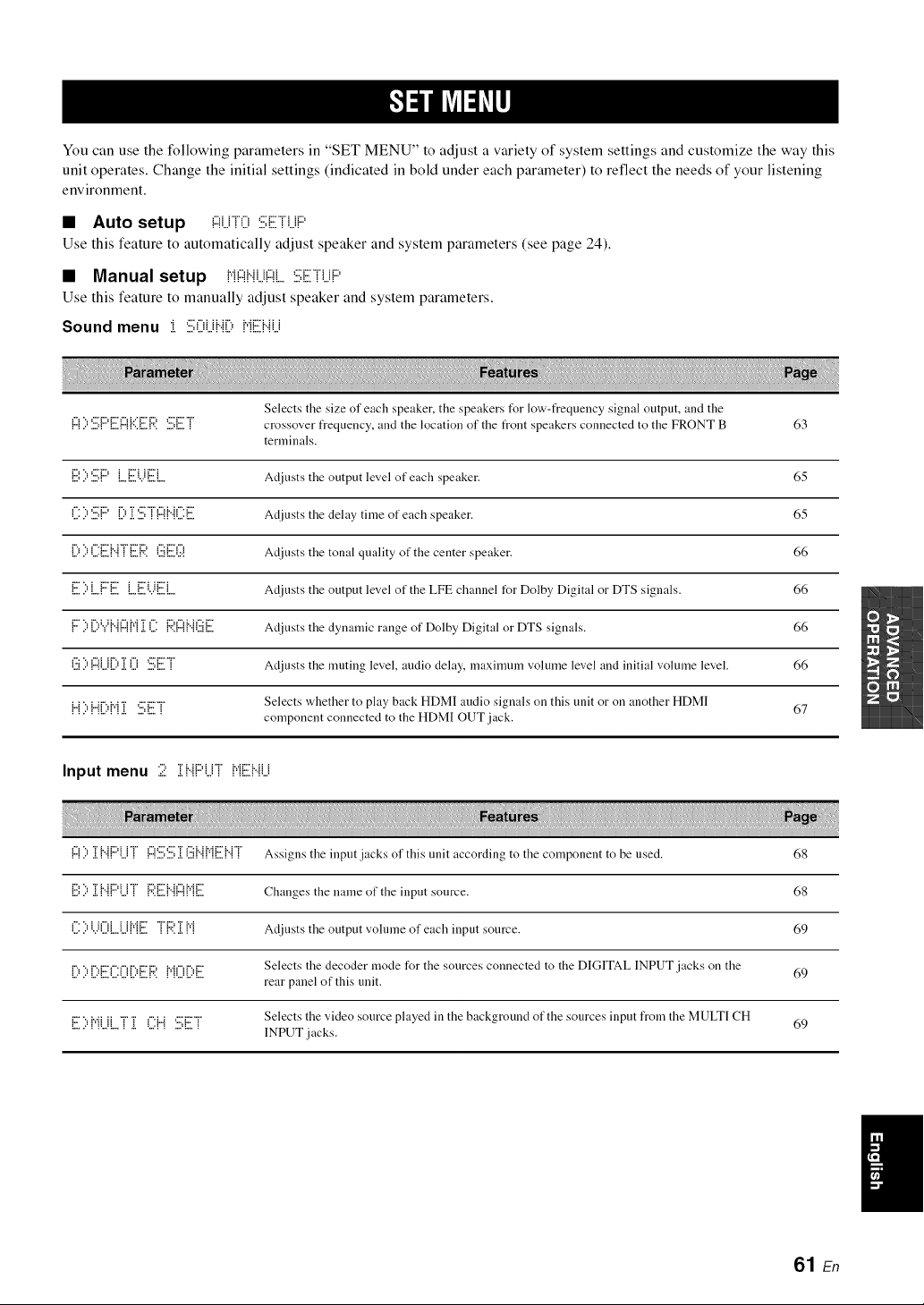
You can use the following parameters in "SET MENU" to adjust a variety of system settings and customize the way this
unit operates. Change the initial settings (indicated in bold under each parameter) to reflect the needs of your listening
environment.
• Auto setup !:::!LirO:iii:Eri..iP
Use this feature to automatically adjust speaker and system parameters (see page 24).
• Manual setup {,i{:::!i..ii...i!:::!i...:iii;Eri...iP
Use this feature to manually adjust speaker and system parameters.
Sound menu :i :ii;Oi..ii..{i){"iEi..iLi
Selects the size of each speaker, the speakers tUr low-t?equency signal output, and the
{:::1i:''.iii;{:::'{i:il1:::1{'::iE {:4'.SET crossover frequency, aud the location of the front speakers connected to the FRONT B 63
terminals.
{i:.i',i:''.i:.i;{:::'{...{i:.ili...i{i:.ii{ Adjusts the output level of each speaker. 65
('.i:i:''.i:.i;{:::'D ii=i'.i:.i;"i"{:::{{"{('.i:{i:.il Adjusts the delay time of each speaker. 65
D i:'('.i:{i:.ii{"{"i"{i:.ilR(:.ii{i:.ili7i Adjusts the tonal quality of the center speaker. 66
{i:.ili:'L.{:::'E {...{i:.ili...i{i:.ilL. Adjusts the output level of the LFE channel for Dolby Digital or DTS signals. 66
{:::"i:'DY{"{{:::{{"{ii.i('.i: {:i?.{:::{{"{(:.ii{i:.il Adiusts the dynamic range of Dolby Digital or DTS signals. 66
i.'.:i){"{U{).L i.i '.:..:,{:..:.! Adiusts the muting level, audio delay, maxinmm volume level and initial volume level. 66
{"{i:'{"{[i:'{"{i!i '.i:i;E"i" Selects whether to play back HDMI audio signals on this unit or on another HDMI 67
component connected to the HDMI OUT jack.
Input menu 2 iii{..{{:::'{..ii{,{Ebli.i
{"{) .L{"{{"'U! {"{'.:::,'.:::,.Li.'i{".{P'{{:::.{".{! Assigns the input .iacks of this unit according to the component to be used. 68
{i:.i',i:'ii.i{".{{:::'{.i"i" {:i?.{i:.ii{".{{:::{{"{{i:.il Changes the name of the input source. 68
{.:)i...ii.iL.Ul'q{:..:. ! 1":'..L1"1 Adiusts the output volume of each input source. 69
i"_"_Pd:::'i"'i"iPd:::'i:',:'i','ii"iPd:::" Selects the decoder mode for the sources connected to the DIGITAL INPUT jacks on the 69
"' " "' "'"'"'" "" " ' '"'" .... rear panel of this unit.
i:::"".=i.,.iiii "r""r _".i...i,:::'i:::'"r" Selects the video source played in the background of the sources input from the MULTI CH
_"""_ ""q"" _ "_" "'_ _ ""q""_ INPUT .iacks. 69
61 En
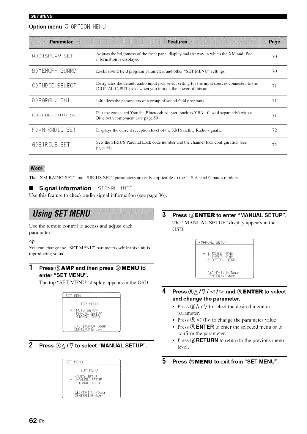
IF#_ljff_i'ij
Option menu 3 0F'[]i0bi iqENU
!:::!)[)]i '.iii;i:::'L.!:::!Y*.iii;iiiiTr Adjusts the brightness of the front panel display arid the way in which the XM and iPod
information is displayed. 70
ii:.i:)MEMi[)i:*;'.Y (:.iiU!:::!i:;;'.[) Locks sound field program parameters and other "SET MENU" settings. 70
i":3 i:i:iiii"?r ii *:::;i:::ii:::i:T Designates the default audio input jack select setting tUr the input sources connected to the 71
......................................... DIGITAL INPUT jacks when you turn on the power of this unit.
[) )i:::G:::!i:;;'.!:::!M= ]i i"i]i Initializes the parameters of a group of sound fiekt programs. 71
Pair the connected Yamaha Bluetooth adapter (such as YBA- 10, sold separately) with a 71
i7 "= iDi i iiZ'"r'f"u"¢T'i...i C'iZ"T"
.................................. Bluetooth component (see page 59).
i:::::,',::',i*ii::;'.!:::![)[i]() :7;E"i" Displays the current reception level of the XM Satellite Radio signals. 72
Sets the SIRIUS Parental Lock code number and the channel lock configuration (see 72
:". ".. ,"" "r i", "r i h"" ="'r""r"
i.'2!2 .D.!,r':..!,i.i.D .D!=.!
page 54).
The "XM RADIO SET" and "SIRIUS SET" parameters are only applicable to the U.S.A. and Canada models.
• Signal information :7;;[ (iiii".i!:::!i_,i i".ii:::'0
Use this feature to check audio signal information (see page 36).
Use the remote control to access and adjust each
parameter.
_.,_,._
You can change the "SET MENU" parameters while this unit is
reproducing sound.
1 Press @AMP and then press @MENU to
enter "SET MENU".
The top "SET MENU" display appears in the OSD.
:;ET tllTi:i'4U
TOP f,lli i.,.II..I
,i, , i:;II..ITO:[;!!7[I..IP
o117]:I;I_NI::II,,Ii".ii::O
[.,i,.] ," [,i,' ] 1:I,.Ip,-'D,::,t,.Iri
[:EI'4TER] a Et& er
2 Press @A / V to select "MANUAL SETUP".
:;ET tllTi:i'4U
TOP f,11i7i.,.ll..I
, i:;It.llO :i;ETLIF'
, :i;]:I:I_N_ll. I i..IFO
[:.,i,.]..[:,i,'] ::I..l_;:.-'Bmc,.*n
i]ENrER] :Erd:..et"
3 Press @ENTERto enter "MANUAL SETUP".
The "MANUAL SETUP" display appears in the
OSD.
,f,lir41%lgl,, :;ETI,,IP
._, !. 17_OLllI0,14EIIU
2 II..17:>l..l'rItEbll..J
:7; OPTION tllTi]'41,J
[:.,i,.] .. [:-,i,';i::I,.11::,. [)ot,ll,.i
[:Ei4-[ I['R:i: Erd:.er
Press @A/V /<1/I> and @ ENTER to select
and change the parameter.
• Press @/\ / Vto select the desired menu or
parameter.
• Press @<:111::> to change the parameter value.
• Press @ENTER to enter the selected menu or to
confirm the parameter.
• Press @RETURN to return to the previous menu
level.
5 Press _MENU to exit from "SET MENU".
62 En
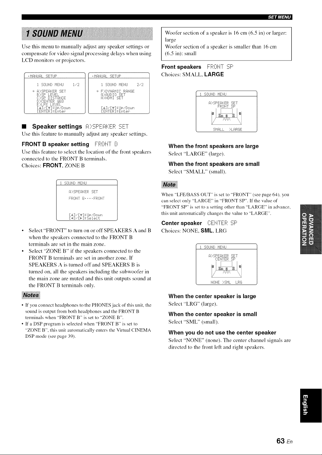
,l_llJff=ri'l_
Use this menu to manually adjust any speaker settings or
compensate for video signal processing delays when using
LCD monitors or projectors.
oI,iF4i_l.._gi..SErUp oMF#_I.._gL:::;ETUP
:1.SOLIN[:,MENU :1..2 :1.SOUbltMENU 2.2
':, FOSPEFIKER SET
S ::,5P LEUEL
{}},Sls t ZS1¢*NC!iT
D)CEbFfER GEQ
}7{) !..FE !..EUEL
[.£] . [,iq ::L.i_:_. Sowr,
[ ENTER ] ::_ir,i:.e_
'_, F::d:)Vbg*M:t:: RaN_I{_8
8)_LC, I 0 SET
H) HI:*11 :i_;lii:T
[.£] . ["F] ',:IJP. C<::,ur*
[:ENTER ] ::E_.,I:.e_"
• Speaker settings !:::!::,:iii;PE!:::{KER:iii;ET
Use this feature to manually adjust any speaker settings.
FRONT B speaker setting FRONT {i:.i:
Use this feature to select the location of the front speakers
connected to the FRONT B terminals.
Choices: FRONT, ZONE B
J. :iX)LINt MENU
_:C,:i_:PEFII<ER :iqii:T
FROWf S ........ FROWf
[:.,i,.]., [:"i"] ;:UP.i}c, wr_
[:.4] [:i,..] : :i_:e1e,:::i:.
Select "FRONT" to turn on or off SPEAKERS A and B
when the speakers connected to the FRONT B
terminals are set in the main zone.
Select "ZONE B" if the speakers connected to the
FRONT B terminals are set in another zone. If
SPEAKERS A is turned off and SPEAKERS B is
turned on, all the speakers including the subwoofer in
the main zone are muted and this unit outputs sound at
the FRONT B terminals only.
• ff you connect headphones to the PHONES jack of this unit, the
sound is output from both headphones and the FRONT B
terminals when "FRONT B" is set to "ZONE B".
• ff a DSP program is selected when "FRONT B" is set to
"ZONE B", this unit automatically enters the Virtual CINEMA
DSP mode (see page 39).
Woofer section of a speaker is 16 cm (6.5 in) or larger:
large
Woofer section of a speaker is smaller than 16 cm
(6.5 in): small
:.,..:.,.,,.,.,: :,.=., ,.,.,:.,.,
Front speakers !!.::u!".!! :::,!....
Choices: SMALL, LARGE
1 :!33LINt MEtlI..I
_:C,:i_:F'EgiKER SET
FROWf 5P
5MALL ::4._:_R61i
When the front speakers are large
Select "LARGE" (large).
When the front speakers are small
Select "SMALL" (small).
When "LFE/BASS OUT" is set to "FRONT" (see page 64), you
can select only "LARGE" in "FRONT SP". If the value of
"FRONT SP" is set to a setting other than "LARGE" in advance,
this unit automatically changes the value to "LARGE".
Center speaker CEHTER :iii;{:"
Choices: NONE, SML LRG
1 SO!..It._t MENU
_:C,SPEgI<FR SET
[:EiI4-fER SP
i1Ol'4E :::-$ML LR6
When the center speaker is large
Select "LRG" (large).
When the center speaker is small
Select "SML" (small).
When you do not use the center speaker
Select "NONE" (none). The center channel signals are
directed to the front left and right speakers.
63 En
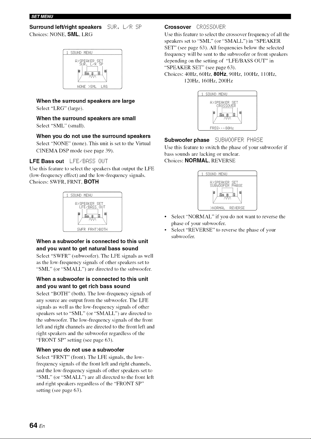
Surround left/right speakers :iii;UR,=LiR SP
Choices:NONE, SML, LRG
-1. %Lli.,l[:, MENU
r"-
!q"NE :::SML I,_
When the surround speakers are large
Select "LRG" (large).
When the surround speakers are small
Select "SML" (small),
When you do not use the surround speakers
Select "NONE" (none), This unit is set to the Virtual
CINEMA DSP mode (see page 39).
LFE Bass out LF[.ii.."[ii',!:::!'.i.i;:iii;()U]
Use this feature to select the speakers that output the LFE
(low-frequency effect) and the low-frequency signals.
Choices: SWFR, FRNT, BOTH
-1. SOI.-11'K;}1Ei'41.-1
g:l::,SPEI::$::ER :!;ET
LFE .-B_:lf;:; OUT
:i;I,,-1FRFR}"4"i-:::BOTi'}
When a subwoofer is connected to this unit
and you want to get natural bass sound
Select "SWFR" (subwoofer). The LFE signals as well
as the low-frequency signals of other speakers set to
"SML" (or "SMALL") are directed to the subwoofer.
When a subwoofer is connected to this unit
and you want to get rich bass sound
Select "BOTH" (both). The low-frequency signals of
any source are output from the subwoofer. The LFE
signals as well as the low-frequency signals of other
speakers set to "SML" (or "SMALL") are directed to
the subwoofer. The low-frequency signals of the front
left and right channels are directed to the front left and
right speakers and the subwoofer regardless of the
"FRONT SP" setting (see page 63).
When you do not use a subwoofer
Select "FRNT" (front). The LFE signals, the low-
frequency signals of the front left and right channels,
and the low-frequency signals of other speakers set to
"SML" (or "SMALL") are all directed to the front left
and right speakers regardless of the "FRONT SP"
setting (see page 63).
Crossover f"i::q"i C" C" f"fi i i:::"D
=.,."F', L.' =.' ,..' L."v" L,, V.
Use this feature to select the crossover frequency of all the
speakers set to "SML" (or "SMALL") in "SPEAKER
SET" (see page 63). All frequencies below the selected
frequency will be sent to the subwoofer or front speakers
depending on the setting of "LFE/BASS OUT" in
"SPEAKER SET" (see page 63).
Choices: 40Hz, 60Hz, 80Hz, 90Hz, 100Hz, 110Hz,
120Hz, 160Hz, 200Hz
-1. :!;OLli,l[_ i'l!i3".LI
I:::RO:i_::iKIl..iE_;i:
FREI::!,,, 8{}H:;i::
Subwoofer phase Si.j[ii:i.,.iOOF[ii:RPH!:::l:iii;E
Use this feature to switch the phase of your subwoofer if
bass sounds are lacking or unclear.
Choices: NORMAL, REVERSE
I. SOI.-11'K_}'1Ei'41.-1
gt::=SF'EF$::ER :gET
SUZ4,-1OOFERPl'g:ff;E
:::-I.40 RI_II::IL }z4:lii:l..i]i:__;1113lii:
• Select "NORMAL" if you do not want to reverse the
phase of your subwoofer.
• Select "REVERSE" to reverse the phase of your
subwoofer.
64 En
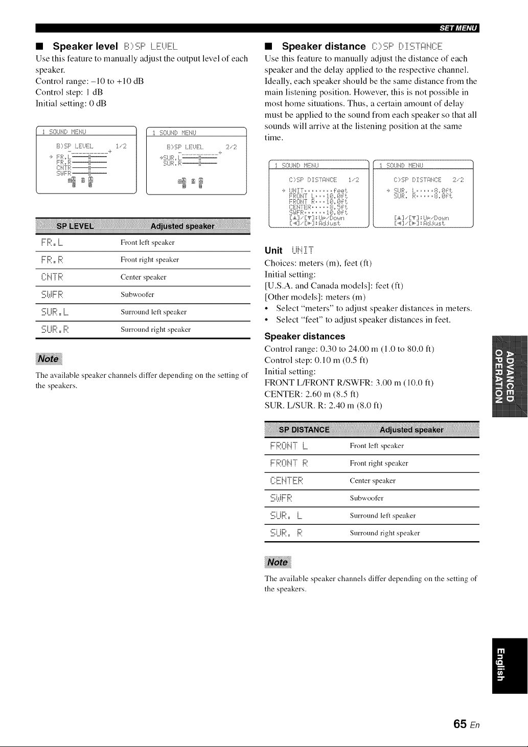
• Speaker level E:;,6F' L.Et,qEL
Use this feature to manually adjust the output level of each
speaker.
Control range: -10 to +10 dB
Control step: 1 dB
Initial setting: 0 dB
1 :i;OUt@IIEHU
S;,SP I,,EUEL :1..-2
....... k
'_ FRo I..il! -
FR,, R--li--
_'i:HTR--li--
:i;k_rm:--H--
_g ag
I :!;Ol..IH!:)HEHU
S;,SP LEUEL :2.-:2
.................. +
.:,'[5UR ,rL--{I--
:i;I..IR,,R--ii--
_m _m
_=lllliff=ri'|_
The available speaker channels differ depending on the setting of
the speakers.
• Speaker distance C ::,:iii;l:::'D i :iii;T!:::ff..iCE
Use this feature to manually adjust the distance of each
speaker and the delay applied to the respective channel.
Ideally, each speaker should be the same distance from the
main listening position. However, this is not possible in
most home situations. Thus, a certain amount of delay
must be applied to the sound from each speaker so that all
sounds will arrive at the listening position at the same
time.
1%I..IHI:) HEi'4LI
i:::::,:[;p [:, ! :[; Ti::fi',iCE :1..-':;;.'
,:, I,,IHIT° ........ Feeb
FRONT I,.°,, ]._h Oi:b
FROHT R°°,I@o@:B
C:EH7ER ..... 8, !=5F i.
[[.,i,.]/["F] ',;I,Jl:,-. [:,O Wr',
1%UHD HE*'4U
{;>SF' P !6 T_::_'.IC:E:2/:2
') 1_ _. J R =r L u .... 8 =r _}J[ b
]_;I, ;R ,r R ......... 8 ,r 8f [ J:,
[:.,i,.:] ., [:"l"[j;;Ul=-.[;,,::,*,,*n
[:._i:1. [:i,°iJs gd.:i *.a:_J:.
{:::'R,, L Front left speaker
Unit UHiT
{:::'R,, {:;?. Front right speaker Choices: meters (m), feet (ft)
C:{".{TR Center speaker Ini ti al setting:
[U.S.A. and Canada models]: feet (ft)
'.i:.i;i.,JFR Subwoofer [Other models]: meters (m)
• Select "meters" to adjust speaker distances in meters.
'.iii;UR= L Surround left speaker
• Select "feet" to adjust speaker distances in feet.
'.i:.i;UR.= P. Surround right speaker
Speaker distances
Control range: 0.30 to 24.00 m (1.0 to 80.0 ft)
Control step: O.10 m (0.5 ft)
Initial setting:
FRONT L/FRONT R/SWFR: 3.00 m (10.0 ft)
CENTER: 2.60 m (8.5 ft)
SUR. L/SUR. R: 2.40 m (8.0 ft)
FR0J..n L Front left speaker
FR0J..n {:;?. Front right speaker
L:1::.1"{! L 1"¢'. Center speaker
6i.,.iFR Subwoofer
'.i:.i;UR= L Surround left speaker
'.::,U{":'.,, 1":'. Surround right speaker
The available speaker channels differ depending on the setting of
the speakers.
/
65 En
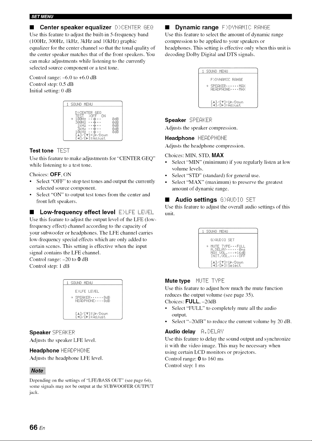
IFF_liff:_iP
• Center speaker equalizer ilI:,I:,CEHTERGE(;:!
Use this feature to adjust the built-in 5-frequency band
(100Hz, 300Hz, lkHz, 3kHz and 10kHz) graphic
equalizer for the center channel so that the tonal quality of
the center speaker matches that of the front speakers. You
can make adjustments while listening to the currently
selected source component or a test tone.
Control range: -6.0 to +6.0 dB
Control step: 0.5 dB
Initial setting: 0 dB
J. :i;81..*_.4DMENU
DI:,CENTER GEg_
TE57 ::;OFF ON
':, 188H:;-:: .. @.. 8dB
:388H::-:: .. @. o 8dB
:l.kH:z: o. "1" " ° 8dB
3kH:z: o.@oo 8dB
:1.8k Hz ,_..l o o,_ 8dB
.£ ,-' _F ',; ,.{=, :,(:)b.}lq
Test tone TE:iii;T
Use this feature to make adjustments for "CENTER GEQ"
while listening to a test tone.
Choices: OFF, ON
• Select "OFF" to stop test tones and output the currently
selected source component.
• Select "ON" to output test tones from the center and
front left speakers.
• Low-frequency effect level E::,L.FE L.EUE[
Use this feature to adjust the output level of the LFE (low-
frequency effect) channel according to the capacity of
your subwoofer or headphones. The LFE channel carries
low-frequency special effects which are only added to
certain scenes. This setting is effective when the input
signal contains the LFE channel.
Control range: -20 to 0 dB
Control step: 1 dB
_, :i;OU_.4DME'4U
E)I..FE I..E-UEL
':, :'.':;PE_KER ........ 8dB
HE_[)PHONE ....... 8dB
[:..,i:j.- [:i,..:j __::k:L:i_.a:_ii:.
Speaker :iii;PE:!:::!KE:R
Adjusts the speaker LFE level.
Headphone {iE:!:::![::.PH0 HE
Adjusts the headphone LFE level.
iiii
Depending on the settings of "LFE/BASS OUT" (see page 64),
some signals may not be output at the SUBWOOFER OUTPUT
jack.
• Dynamic range i:::::,D'.,.'H{:::{N:[C RF{H(iiiE
Use this feature to select the amount of dynamic range
compression to be applied to your speakers or
headphones. This setting is effective only when this unit is
decoding Dolby Digital and DTS signals.
_. :}!;(:}UNDMENU
F) DYNAII:[8 Rg_HGE
':, :'.':;PE_gER ........ _dR::::
[:.,i,,:].-'[:,{,':j:;UP . [::,,::,*.,m
[:._i:1. [:i,-:i agd.:i *.a:_i:.
Speaker :iii;PE:!:::!KE:R
Adjusts the speaker compression.
Headphone ii {iii:{:::{1:::,1:::'{ii:::ii".Jii::
Adjusts the headphone compression.
Choices: MIN, STD, MAX
• Select "MIN" (minimum) if you regularly listen at low
volume levels.
• Select "STD" (standard) for general use.
• Select "MAX" (maximum) to preserve the greatest
amount of dynamic range.
• Audio settings (iii::,!:::!U[::,:[0 :iii;ET
Use this feature to adjust the overall audio settings of this
unit.
:1. :i;OLIND }qii:i'4LI
7_:,i:_DT': :!;ET
.:, }dU'TI!i -YPE _ _. FULL
_4=r DE[.RY ....... 8p*:ii
I _'41{ Y ,r _''_(}L, _ u _ u u OFF
[:.,i,,:].-'[:,{,':j:;I..b_. Do*.,.m
Mute type {,{i...iijiii:TYPE[
Use this feature to adjust how much the mute function
reduces the output volume (see page 35).
Choices: FULL,-20dB
• Select "FULL" to completely mute all the audio
output.
• Select "-20dB" to reduce the current volume by 20 dB.
Audio delay !:::!,,[)E:L!:::!Y
Use this feature to delay the sound output and synchronize
it with the video image. This may be necessary when
using certain LCD monitors or projectors.
Control range: 0 to 160 ms
Control step: 1 ms
66 En
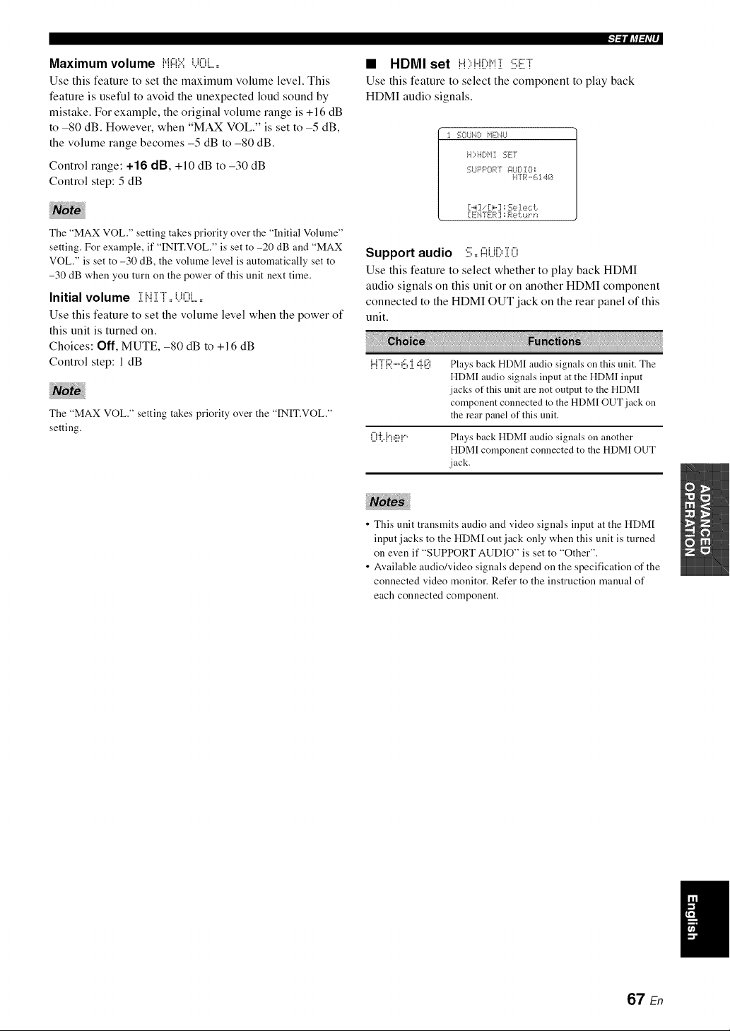
Maximum volume N!:::!::.::i...K)i......
Use this feature to set the maximum volume level. This
feature is useful to avoid the unexpected loud sound by
mistake. For example, the original volume range is +16 dB
to -80 dB. However, when "MAX VOL." is set to -5 dB,
the volume range becomes -5 dB to -80 dB.
Control range: +16 dB, +10 dB to -30 dB
Control step: 5 dB
The "MAX VOL." setting takes priority over the "Initial Volume"
setting. For example, if "INIT.VOL." is set to -20 dB and "MAX
VOL." is set to -30 dB, the volume level is automatically set to
-30 dB when you turn on the power of this unit next time.
Initial volume i Hi T ==i.)Oi......
Use this feature to set the volume level when the power of
this unit is turned on.
Choices: Off, MUTE, -80 dB to +16 dB
Control step: 1 dB
The "MAX VOL." setting takes priority over the "INIT.VOL."
setting.
• HDMI set H;,H[;,Ni :iii:ET
Use this feature to select the component to play back
HDMI audio signals.
1%UN[> MENU
H)HDMI :;ELY
:;UPPOPT _?UD!O=
H71_'-'614_)
[1._ili[:i,-?;;Se 1ecL.
[ EI"4"gER"aRe b.a"i"*
Support audio 5==!:::!U[)i0
Use this feature to select whether to play back HDMI
audio signals on this unit or on another HDMI component
connected to the HDMI OUT jack on the rear panel of this
unit.
{...nR ..-.6 i ,::i.(:.!i Plays back HDMI audio signals on this unit. The
HDMI audio signals input at the HDMI input
jacks of this unit are not output to the HDMI
component connected to the HDMI OUT jack on
the rear panel of this unit.
O'i:.{'7_!:.!=!.... Plays back HDMI audio signals on another
HDMI component connected to the HDMI OUT
jack.
• This unit transmits audio and video signals input at the HDM[
input jacks to the HDM[ out jack only when this unit is turned
on even if "SUPPORT AUDIO" is set to "Other".
• Available audio/video signals depend on the specification of the
connected video monitor. Refer to the instruction manual of
each connected component.
/
67 En
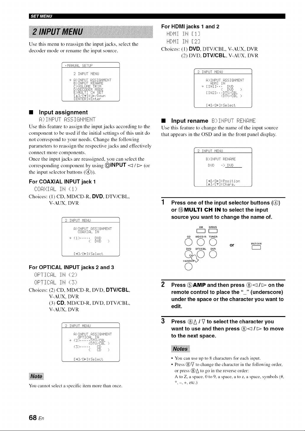
IFFilJff:_iP
Use this menu to reassign the input jacks, select the
decoder mode or rename the input source.
. It*'-:}bll..ll::fl..SETI..IF'
2 !I,.IF:'LFfHEHU
':, _:0 IbIPU-f i:_SSISHt'1EH-[
S ;, I HPI.JT REHI:It'IE
{; ;,_.._()l.,t._l"11iii7RIH
B;,!I)ECO[)ER I10!:)E
E)I"IULTI {::H SET
[:Ei47I[-P] _E_"d:.er
• Input assignment
="_".. "r i. H"...."i"r" ="_"'_"" "r _"q. H.Ar"L ;"r"
: : ...:. : :: .... : : : ......... .:. ...: : :: ::...: : :
Use this feature to assign the input jacks according to the
component to be used if the initial settings of this unit do
not correspond to your needs. Change the following
parameters to reassign the respective jacks and effectively
connect more components.
Once the input jacks are reassigned, you can select the
corresponding component by using (_INPUT <:1 / t:> (or
the input selector buttons (@)).
For COAXIAL INPUT jack 1
_".1","_:..: "r _"d "r i. ; ..' 4 ".
, , ,..., ... = ,..., = ,..= = = =
•.......: :: : .:. : ::... .=.:: ...:...
Choices: (1) CD, MD/CD-R, DVD, DTV/CBL
V-AUX, DVR
2 IHPtIrT HEHU
_?::,IHF:I..i7g_SS!Si,_HEi'4-[
80g::-::I _?L IH
'_, ,::I ::.......... I;:,t)!:;,
,:: I;:,t._D ::,
[[..,i] [[i,..] _ii;e 1e,:::i:.
For OPTICAL INPUT jacks 2 and 3
.....:......r..=...........: .=.: : .. =:...
Choices: (2) CD, MD/CD-R, DVD, DTV/CBL,
V-AUX, DVR
(3) CD, MD/CD-R, DVD, DTV/CBL
V-AUX, DVR
1;71Ii,41::'l..IrHlii.qLI
i:4;,! HPl.J7 _:!SSI8H_'11iH7
OPT ICI::_[.IN
':, (2; ....... D7 U..CBL
,::[2.b{;BL ;,
,::3 ::.......... 8D
,:: 80 ;,
[[..,i] [[i,..] _ii;e 1e,:::i:.
You cannot select a specific item more than once.
For HDMI jacks 1 and 2
i...ii ii,i i i i'..i i i i
: ::.,. : : .l. .:,: : :,..:, .,l
I 11% I,,I ,I, ,I, I I I- ,,,,, ,,I
!"!L.q'!.!. 2!"! LZ."
Choices: (1) OVO, DTV/CBL, V-AUX, DVR
(2) DVD, DTV/CBL, V-AUX, DVR
2 IHI::'UT f+112i,41,,I
g;, IHPUT _::_SS18HHIii_'47
l'.l[>bl! IH
':, [1Ii'4!1i.,. DUD
,:: DUD ::,
[11i'42],,. [:,-[U..CBL
,:[DTtL-{;17?L ;,
[i"i ] .- [ii" ] _ 1i_ ], e,:::i:,
• Input rename iiii:::,iHi:::'i_ri i::I:EH!:::!HiE
Use this feature to change the name of the input source
that appears in the OSD and in the front panel display.
1;71IHI::'UT fqTi]'41,,I
S;, Ii,.I!::'I,,IT REi41::IHE
I;:,t._l;:..... > i}t £:,
[[._4] .-'[[i,..] 1;PO:ii:[i:. :[,::?f '_
Press one of the input selector buttons (@)
or @MULTI CH IN to select the input
source you want to change the name of.
MD/CD-R TUNER
DVD DTV/CBL OVR
©
©
_ULTIOHIN
or U---I
Press @AMP and then press @<1/C> on the
remote control to place the "_" (underscore)
under the space or the character you want to
edit.
Press ®A / 2 to select the character you
want to use and then press ®<1 / I;> to move
to the next space.
• You can use tip to 8 characters for each input.
• Press @V to change the character in the following order,
or press @A to go in the reverse order:
A to Z, a space, 0 to 9, a space, a to z, a space, symbols (#,
*, -, +, etc.)
68 En
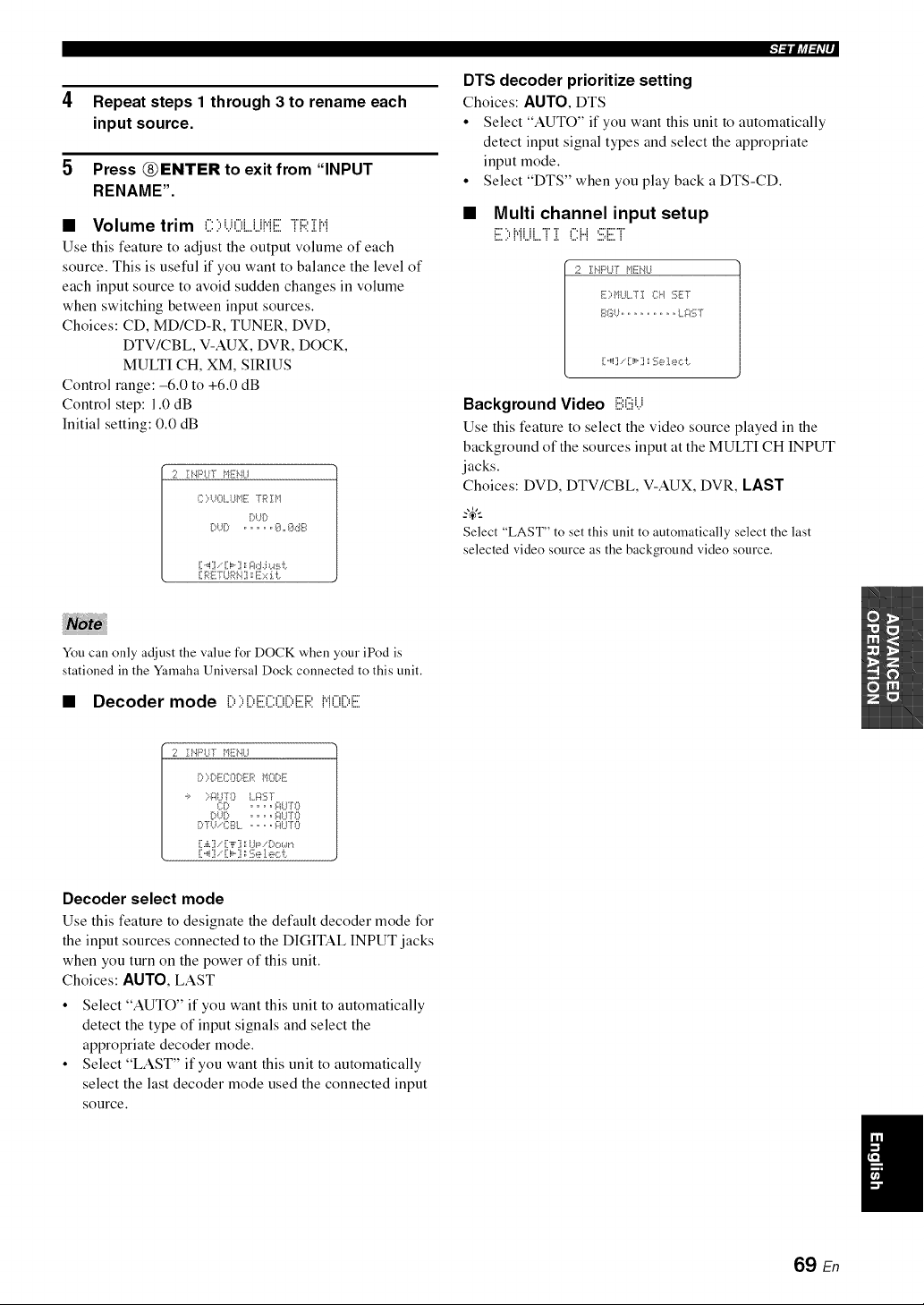
4 Repeat steps 1 through 3 to rename each
input source.
5 Press _ENTER to exit from "INPUT
RENAME".
• Volume trim C)UOLUHE TRill
Use this feature to adjust the output volume of each
source. This is useful if you want to balance the level of
each input source to avoid sudden changes in volume
when switching between input sources.
Choices: CD, MD/CD-R, TUNER, DVD,
DTV/CBL V-AUX, DVR, DOCK,
MULTI CH, XM, SIRIUS
Control range: -6.0 to +6.0 dB
Control step: 1.0 dB
Initial setting: 0.0 dB
12 IHPIY[ HEHLI
{:)UOLUHE TR IH
DUD
[ ,_i] , - i,,,] =,;i:b::_.:i*.4:i_i:
:l_lliff_i'l ,
DTS decoder prioritize setting
Choices: AUTO, DTS
• Select "AUTO" if you want this unit to automatically
detect input signal types and select the appropriate
input mode.
• Select "DTS" when you play back a DTS-CD.
• Multi channel input setup
_"" ",._..._ H ";" ";' :",_ _ ="'r"";
:_... : :._.:_. : .:.._.: : ..,..:.,.. :
2 ]:HPLiI" HEN{,i
EI:=ItI..II.,TI 04 SET
_{_G{._.................. {,,_:3 g
[ ,,,i] ,- [ i,,,] _:i_;e1e_:::i:,
Background Video E:(iiii...i
Use this feature to select the vide() source played in the
background of the sources input at the MULTI CH INPUT
jacks.
Choices: DVD, DTV/CBL V-AUX, DVR, LAST
Select "LAST" to set this unit to automatically select the last
selected video source as the background video source.
You can only adjust the value for DOCK when your iPod is
stationed in the Yamaha Universal Dock connected to this unit.
• Decoder mode :::::::::::::::::::::::::::::::::::::::::::HO[:,E
2 II..4PI,,IT HEi'4LI
[:0 [:,EI:::Oi)ER HI::)I:::,E
.:, ::-_iLI70 LaST
CD .... i::ii..IT(3
DU[? .... _:_LE0
DTU.-CI_:_L .. o. i::IUTO
[:.,i,,] ,-'[:"i"] ;;U_=,!:)o*.,.m
[:._i] . [:i,-] aSe I e_:::i:.
Decoder select mode
Use this feature to designate the default decoder mode for
the input sources connected to the DIGITAL INPUT jacks
when you turn on the power of this unit.
Choices: AUTO, LAST
• Select "AUTO" if you want this unit to automatically
detect the type of input signals and select the
appropriate decoder mode.
• Select "LAST" if you want this unit to automatically
select the last decoder mode used the connected input
source.
69 En
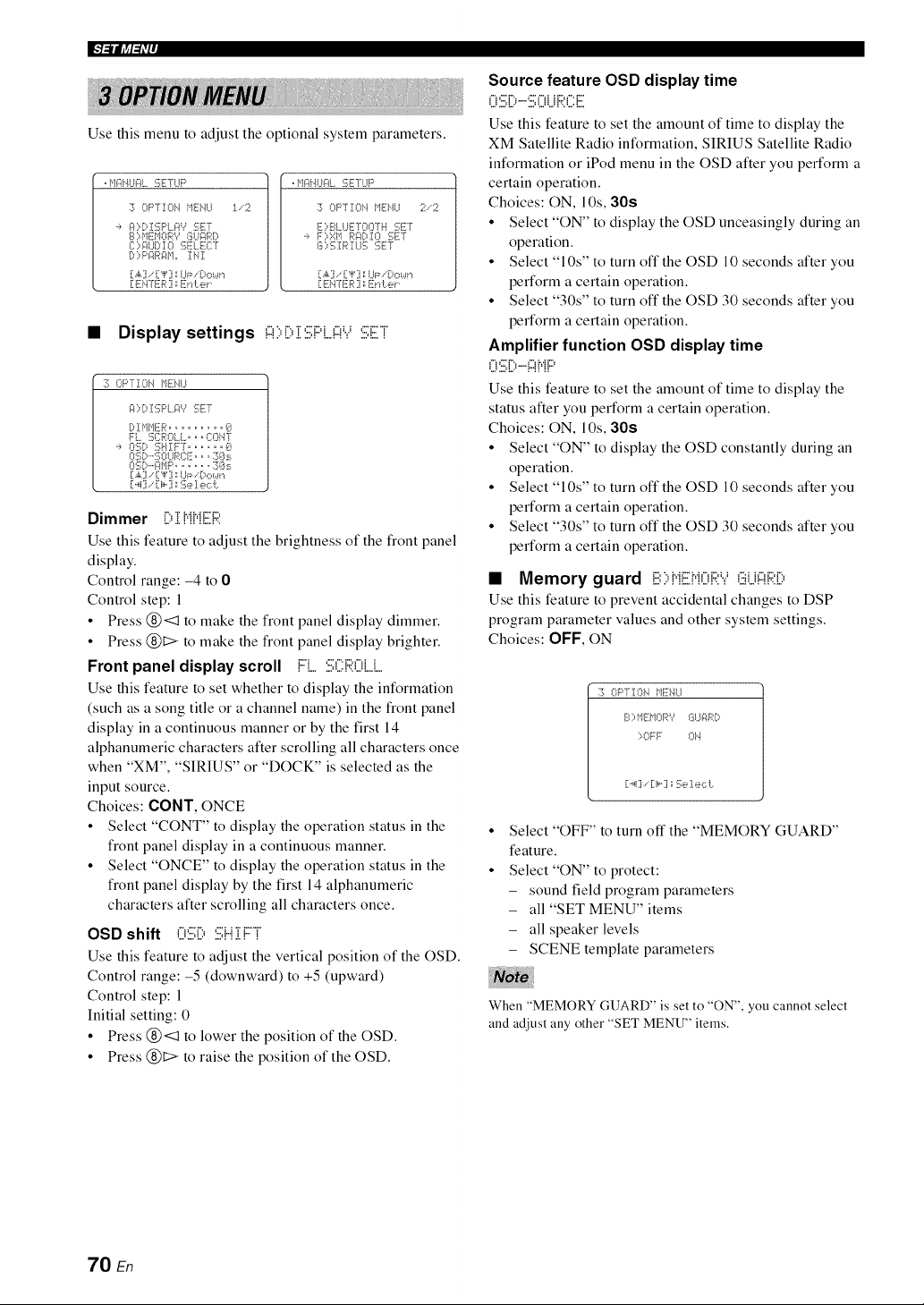
IF]_l(a:_iP
__________________________________________________________________________________________________________________________________________________________________________________________________________________________________________________________________________________________________________________________________________________________________________________________________________________________________________________
Use this menu to adjust the optional system parameters.
. f,l¢4i'_l..l¢4L%TfUP
:i_ OF'TIO_'_ MIH,_I,.I :1,,-2
':, gODISPL.i:_? :i!;ET
S 1:,blEMOR"/ SI..li:_R[:,
I11:1:,It:}l.] DI I[[[I:_;E[._qi]:-[
D) Pi::_R_:_M,r!NI
[1.,i,.] .. [1",i,'] :',UI;_-.--:,{::¢,.Jr_
!:E _q'E .:7:',Eud:.el
, f'l¢4i'_l..l¢4L:":;E'rLIF'
:30F'TIOhl ME!.JU 2,-2
E::,BL LIETOO'rH :!i;FT
':, FI:,ZIt Ri:I!)IO 5FT
S::,:i_I RI U:i_ :iqi];T
[:.,i,.:],. [:,i,'] :',UI::-,-[:,{::¢,.Jr_
[:ENTER ] ::Et'd:.el
• Display settings !:::!::,Di:iii;F'L!:::!'.i:iii;Ei
:i_ OPTION _lEi'41..I
_ )I:::,]::i;F'L _:Pv'5FT
[:,! @IER ......... 0
Fi.. 3CROt.t... {i:Oi'.lT
.:, O5!1:,5HII::T. ..... 0
O:[_D'-'SOUF:(TE,,o:7]<_:_.
OS[>-';:il_]P....... 3Os
[[.,i,,]/[[,l,'[j ',;I.JP/[)o_._r'l
[1._4] . [:i,°] _:'!;eI ec L
Dimmer D i J"iJ"iER
Use this feature to adjust the brightness of the front panel
display.
Control range: -4 to 0
Control step: 1
• Press (_)<:1 to make the front panel display dimmer.
• Press (_)1::> to make the front panel display brighter.
Front panel display scroll FL :i:.i;ii:ROL.J....
Use this feature to set whether to display the information
(such as a song title or a channel name) in the front panel
display in a continuous manner or by the first 14
alphanumeric characters after scrolling all characters once
when "XM", "SIRIUS" or "DOCK" is selected as the
input source.
Choices: OONT, ONCE
• Select "CONT" to display the operation status in the
front panel display in a continuous manner.
• Select "ONCE" to display the operation status in the
front panel display by the first 14 alphanumeric
characters after scrolling all characters once.
OSD shift O:iii;D :iii;i...iiFT
Use this feature to adjust the vertical position of the OSD.
Control range: -5 (downward) to +5 (upward)
Control step: 1
Initial setting: 0
• Press (_)<:1 to lower the position of the OSD.
• Press (_)1::> to raise the position of the OSD.
Source feature OSD display time
U1:.:,!.._-.1:.:,UU !.,::L.!._
Use this feature to set the amount of time to display the
XM Satellite Radio information, SIRIUS Satellite Radio
information or iPod menu in the OSD after you perform a
certain operation.
Choices: ON, lOs, 30s
• Select "ON" to display the OSD unceasingly during an
operation.
• Select "10s" to turn off the OSD 10 seconds after you
perform a certain operation.
• Select "30s" to turn off the OSD 30 seconds after you
perform a certain operation.
Amplifier function OSD display time
_% _"" i",, _"_ i.,.i i"_
"m=.m=In ' I II II
Use this feature to set the amount of time to display the
status after you perform a certain operation.
Choices: ON, 10s, 30s
• Select "ON" to display the OSD constantly during an
operation.
• Select "10s" to turn off the OSD 10 seconds after you
perform a certain operation.
• Select "30s" to turn off the OSD 30 seconds after you
perform a certain operation.
• Memory guard E:I:,i"iEMOi::I:'.,.'(iiii.j;:fi::i:ii:,
Use this feature to prevent accidental changes to DSP
program parameter values and other system settings.
Choices: OFF, ON
:i¢ OPTIOI'4 f+117i]'41,,1
S::,MEMORV SI,,I¢IRD
>OFF O1"4
[i'_4i] .'" [i i_"1i _ 1[];_], e ,:::i:,
Select "OFF" to turn off the "MEMORY GUARD"
feature.
Select "ON" to protect:
- sound field program parameters
- all "SET MENU" items
- all speaker levels
- SCENE template parameters
When "MEMORY GUARD" is set to "ON", you cannot select
and adjust any other "SET MENU" items.
70 En
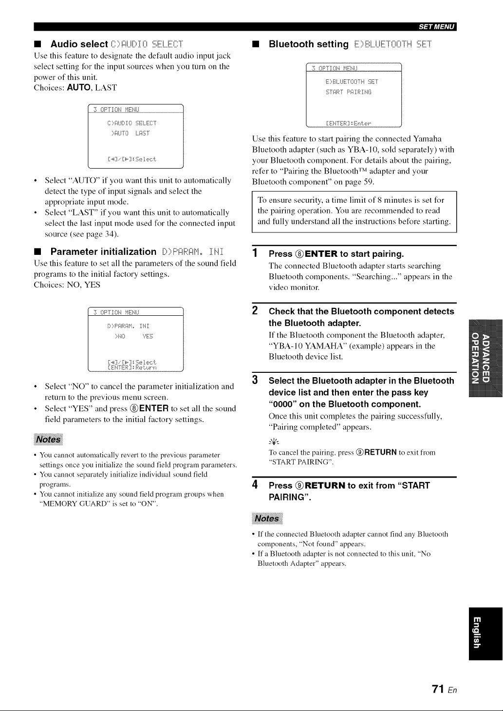
• Audio select (:::::,#J[:,:[ 0 :i;i;ELE(:::T
Use this feature to designate the default audio input jack
select setting for the input sources when you turn on the
power of this unit.
Choices: AUTO, LAST
:30Fq-]:Oi'.l ME!.,li..i
I::);A.IDI0 .....,li I.,_.......[
>-_:<1TO I.._:_:{;T
• Select "AUTO" if you want this unit to automatically
detect the type of input signals and select the
appropriate input mode.
• Select "LAST" if you want this unit to automatically
select the last input mode used for the connected input
source (see page 34).
• Parameter initialization [::,::,P!:::!R!:::!M,=:[H:[
Use this feature to set all the parameters of the sound field
programs to the initial factory settings.
Choices: NO, YES
:2_OPTION }'lEi'41..I
[:* ::=P{7:}R _:_M ,, I i"{ :[
>l<l Yli-S
[:,_i] , [:i,-] :;Se 1e,:::i:..
[:ENTER ] _[%4:._._1,i._
• Select "NO" to cancel the parameter initialization and
return to the previous menu screen.
• Select "YES" and press (_)ENTER to set all the sound
field parameters to the initial factory settings.
• You cannot automatically revert to the previous parameter
settings once you initialize the sound field program parameters.
• You cannot separately initialize individual sound field
programs.
• You cannot initialize any sound field program groups when
"MEMORY GUARD" is set to "ON".
Bluetooth setting E::,iiii:LLiETOOTH:iii;ET
::_ OPTION _'llii:i'_l,,I
E ::,BUJE TO07 H E;ET
gf_:_RT P;:<[ R :[NG
[:ENTER ] _E_"_te_
Use this feature to start pairing the connected Yamaha
Bluetooth adapter (such as YBA-I 0, sold separately) with
your Bluetooth component. For details about the pairing,
refer to "Pairing the Bluetooth TM adapter and your
Bluetooth component" on page 59.
To ensure security, a time limit of 8 minutes is set for
the pairing operation. You are recommended to read
and fully understand all the instructions before starting.
1 Press (_ENTERto start pairing.
The connected Bluetooth adapter starts searching
Bluetooth components. "Searching..." appears in the
video monitor.
2
3
4
Check that the Bluetooth component detects
the Bluetooth adapter.
If the Bluetooth component the Bluetooth adapter,
"YBA-10 YAMAHA" (example) appears in the
Bluetooth device list.
Select the Bluetooth adapter in the Bluetooth
device list and then enter the pass key
"0000" on the Bluetooth component.
Once this unit completes the pairing successfully,
"Pairing completed" appears.
_%,._
To cancel the pairing, press @RETURN to exit from
"STARTPAIRING".
Press _RETURN to exit from "START
PAIRING".
• ff the connected Bluetooth adapter cannot find any Bluetooth
components, "Not found" appears.
• If a Bluetooth adapter is not connected to this unit, "No
Bluetooth Adapter" appears.
71 En
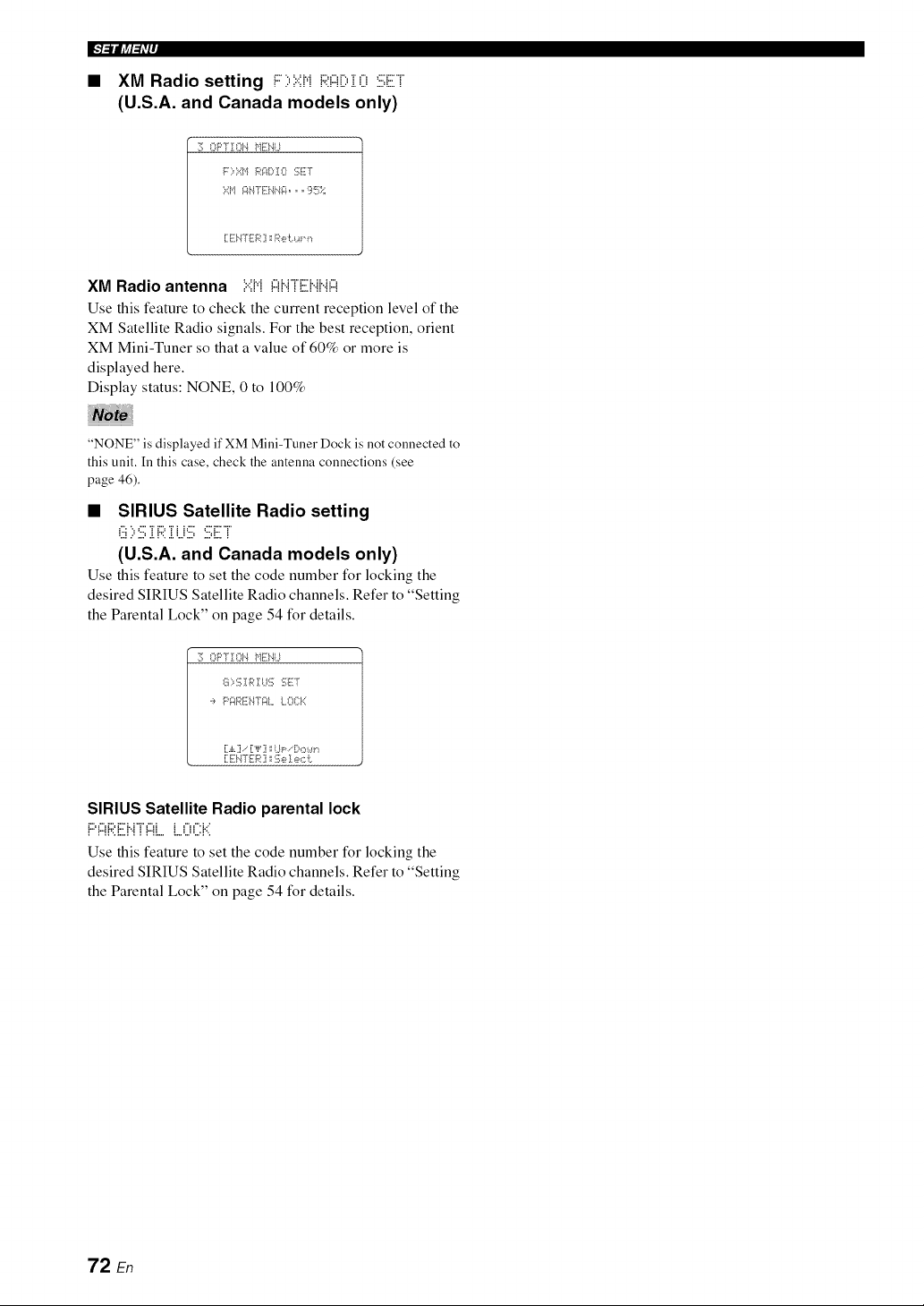
IF]_lJff_iP
• XM Radio setting i:::::,:?:;HRAil:,i O :iii;ET
(U.S.A. and Canada models only)
11_OPTION _lEi'41.1
F::=Xbl R_:II)!O :!i_liilT
:;:',1_1_iI-fli;i4iIi;4,,, lii_!_i;;-;;
[:ENTER ] ::Re i:.c_._,,
XM Radio antenna ....._.,._c,_..rn:::_..,.._,,
Use this feature to check the current receptkm level of the
XM Satellite Radio signals. For the best reception, orient
XM Mini-Tuner so that a value of 60% or more is
displayed here.
Display status: NONE, 0 to 100%
"NONE" is displayed if XM Mini-Tuner Dock is not connected to
this unit. In this case, check the antenna connections (see
page 46).
• SIRIUS Satellite Radio setting
i ..: ", ,... i i.., i i i ,... ,... i... i
%! ..' ..., .!. !'...!. ,..,..., ....q... !
(U,S,A, and Canada models only)
Use this feature to set the code number for locking the
desired SIRIUS Satellite Radio channels. Refer to "Setting
the Parental Lock" on page 54 for details.
:i¢ OPTIOI'4 _+11iii'41,,I
S 1:,1[_IR ! I..l:!];:iqiT:T
:, Pir4RI77:I4-f¢IILO{]:K
[1ENTER ]i _2;e I e,:::i:.
SIRIUS Satellite Radio parental lock
i": :": i": i"" i. l ";" :": i i :": :", i,.'
I I II '=I.,.I I I I ll.m l.m =..= =.,.= I ',
Use this feature to set the code number for locking the
desired SIRIUS Satellite Radio channels. Refer to "Setting
the Parental Lock" on page 54 for details.
72 En
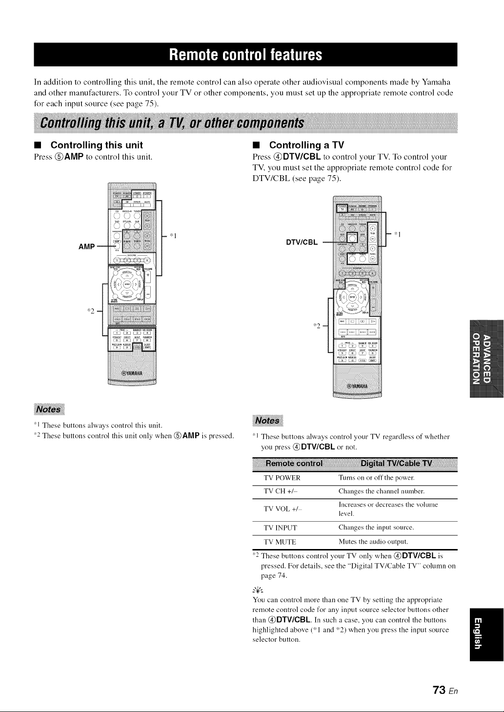
In addition to controlling this unit, the remote control can also operate other audiovisual components made by Yamaha
and other manufacturers. To control your TV or other components, you must set up the appropriate remote control code
for each input source (see page 75).
• Controlling this unit
Press @AMP to control this unit.
AMP --
*1
• Controlling a TV
Press @DTV/CBL to control your TV. To control your
TV, you must set the appropriate remote control code for
DTV/CBL (see page 75).
DTV/C B L
*2
!_;i/i!iiiiiiiii_i;i!iiiii¸i¸III;¸i¸;iiiiiii¸iii!¸iJil;¸i¸;i¸ili¸i¸ilii¸;ii¸I¸I!{¸iil);¸;{i;{i;{iiii}iii¸i¸!
-- *1
1 These buttons always control this unit.
_2 These buttons control this unit only when @AMP is pressed.
1 These buttons always control your TV regardless of whether
you press @ DTWCBL or not.
TV POWER Turns on or off the power.
TV CH +_ Changes the channel number.
Increases or decreases the volume
TV VOL +/
level.
TV INPUT Changes the input source.
TV MUTE Mutes the audio output.
*2 These buttons control your TV only when @DTV/CBL is
pressed. For details, see the "Digital TV/Cable TV" column on
page 74.
_%,._
You can control more than one TV by setting the appropriate
remote control code for any input source selector buttons other
than @DTV/CBL In such a case, you can control the buttons
highlighted above (*1 and *2) when you press the input source
selector button.
73 En
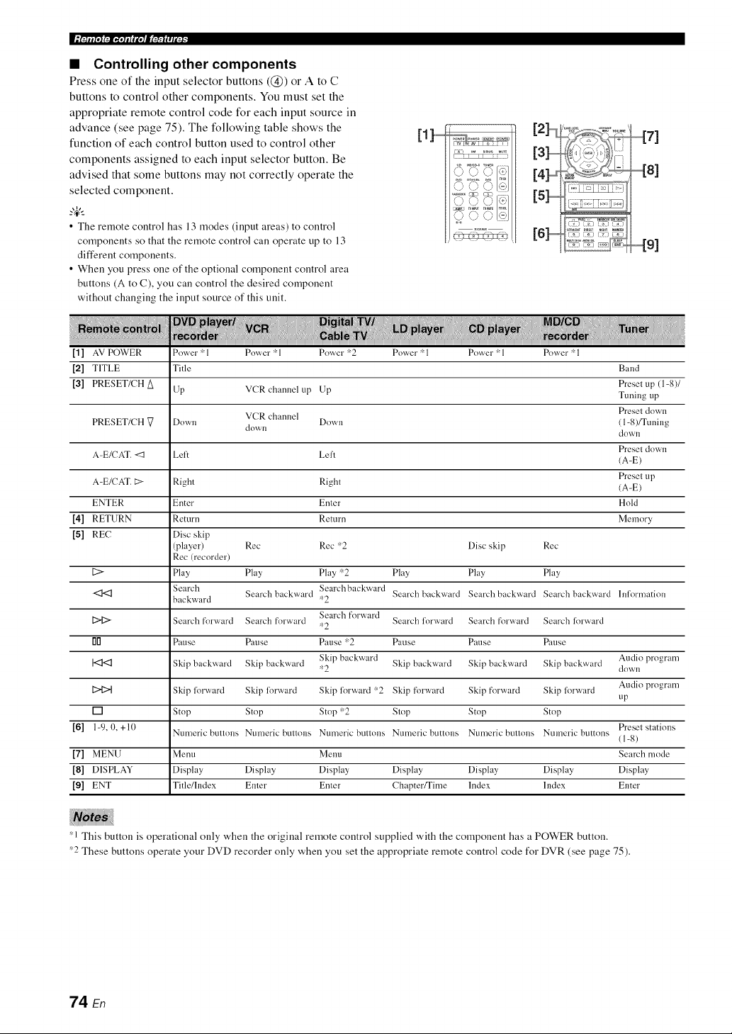
• Controlling other components
Press one of the input selector buttons ((_)) or A to C
buttons to control other components. You must set the
appropriate remote control code for each input source in
advance (see page 75). The following table shows the
function of each control button used to control other
components assigned to each input selector button. Be
advised that some buttons may not correctly operate the
selected component.
_%,._
• The remote control has 13 modes (input areas) to control
components so that the remote control call operate up to 13
different components.
• When you press one of the optional component control area
buttons (A to C), you can control the desired component
without changing the input source of this unit.
[1]...............
\_' k) .?
v/' %/ v_
_J \J
[2],,,,,,,,,_
[4],,,,,,,,_
[6]..............
[1] AV POWER Power *1 Pow,'er 'rq Pow,'er 'r:2 Power * 1 Pow,'er 'rq Power * 1
[2] TITLE Title Band
Preset up (1-8)1
[3] PRESET/CH A Up VCR channel up Lip Tuning up
VCR channel Preset down
PRESET/CH [7 Down Down 11-8)/Tuning
down dowi1
Presel dowi1
A-E/CAT. <1 Lelt Lelt /A-E)
Presel up
A-E/CAT. E:> Right Right /A-E)
ENTER Enter Enter Hold
[4] RETURN Return Return Memory
[5] REC Disc skip
(player) Rec Rec *2 Disc skip Rec
Rec/recorder)
[2> Play Play Play *2 Play Play Play
Search Search backward Searchbackward Search backward Search backward Search backward hflormation
backward *2
Search forward
[2>12> Search forward Search forward Search lorward Search [k_rward Search forward
*2
rlD Pause Pause Pause *2 Pause Pause Pause
Skip backward Audio program
I<I<1 Skip backward Skip backward *2 Skip backward Skip backward Skip backward down
Audio program
[2>{2>t Skip forvvrard Skip forvvrard Skip forward r¢2 Skip forward Skip forward Skip lorward
tip
[] Stop Stop Stop *2 Slop Stop Stop
[6] 1-9, 0, +10 Ntlmeric btlnolls Ntlmeric btlnolls Ntlmeric btlnolls Ntln?eric buttons Numeric btlnolls Numeric buttons Preset stations
11-8)
[7] MENU Menu Metal Search mode
[8] DISPLAY Display Display Display Display Display Display Display
[9] ENT Tifle/lndex Enter Enter Chapter/Time Index Index Enter
1 This button is operational only when the original remote control supplied with the component has a POWER button.
_2 These buttons operate your DVD recorder only when you set the appropriate remote control code for DVR (see page 75).
74 En
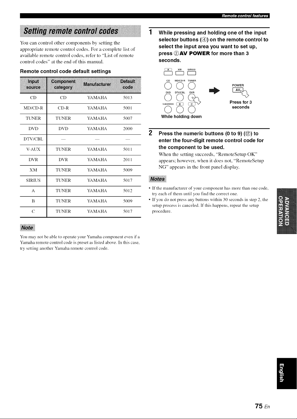
You can control other components by setting the
appropriate remote control codes. For a complete list of
available remote control codes, refer to "List of remote
control codes" at the end of this manual.
Remote control code default settings
CD CD YAMAHA 5013
MD/CD-R CD-R YAMAHA 5001
TUNER TUNER YAMAHA 5007
DVD DVD YAMAHA 2000
DTV/CBL -- -- --
V-AUX TUNER YAMAHA 5011
DVR DVR YAMAHA 2011
XM TUNER YAMAHA 5009
SIRIUS TUNER YAMAHA 5017
A TUNER YAMAHA 5012
B TUNER YAMAHA 5009
C TUNER YAMAHA 5017
While pressing and holding one of the input
selector buttons (@) on the remote control to
select the input area you want to set up,
press @AV POWER for more than 3
seconds.
XM SIRIUS
EZ3 r---I EZ3
MD/CD-R TUNER
0©©
DVD DTV/CBL DVR
V-AUXIDOCK_ ...............
000
While holding down
POWER
Press for 3
seconds
2
Press the numeric buttons (0 to 9) (@) to
enter the four-digit remote control code for
the component to be used.
When the setting succeeds, "RemoteSetup OK"
appears; however, when it does not, "RemoteSetup
NG" appears in the front panel display.
• ff the manufacturer of your component has more than one code,
try each of them until you find the correct one.
• If you do not press any buttons within 30 seconds in step 2, the
setup process is canceled. If this happens, repeat the setup
procedure.
You may not be able to operate your Yamaha component even if a
Yamaha remote control code is preset as listed above. In this case,
try setting another Ymnaha remote control code.
75 En
This unit has additional menus that are displayed in the
front panel display. The advanced setup menu offers
additional operations to adjust and customize the way this
unit operates. Change the initial settings (indicated in bold
under each parameter) to reflect the needs of your
listening environment.
• Only @STANDBY/ON, @PROGRAM <1 / t>, and
@STRAIGHT are effective while you are using the advanced
setup menu.
• No other operations call be made while you are using the
advanced setup menu.
• The advanced setup menu is only available ill the front panel
display.
1 Press @STANDBY/ON to set this unit to the
standby mode.
2
Press and hold @TONE CONTROL and
then press @STANDBY/ON to turn on this
unit.
This unit turns on, and the advanced setup menu
appears in the front panel display.
3
Press @PROGRAM <1 It> to select the
parameter you want to adjust.
The name of the selected parameter appears in the
front panel display.
4 Press @STRAIGHT repeatedly to change
the selected parameter setting.
5 Press @STANDBY/ON to confirm your
selection and set this unit to the standby
mode.
?_t
The settings you made are reflected next time you turn on this
unit.
• Speaker impedance :iii;i:::'i Mi:::'==
(U.S.A. and Canada models only)
Use this feature to set the speaker impedance of this unit
so that it matches that of your speakers.
Choices: 8_2 MIN, 6f_ MIN
• Select "8f2 MIN" to set the speaker impedance to 8 f_.
• Select "6f_ MIN" to set the speaker impedance to 6 f_.
Front(A or B)
Theimpedanceof each
8f.)MIN Center speaker must be 8 _Qor
higher.
Surround
6f,) MIN
Front (A or B)
The impedance of each
Center speaker must be 6 _Q or
higher.
Surround
• SIRIUS Satellite Radio Parental Lock
code number reset :iii;:iii;i::i:i:::'ili..i
Use this feature to set the code number for the SIRIUS
Satellite Radio Parental Lock feature to the initial factory
setting.
Choices: RESET, CANCEL
• Select "RESET" to set the code number to the initial
factory setting.
• Select "CANCEL" to set the code number to the initial
factory setting.
Even if you set "SSR PIN" to "RESET", this unit does not unlock
the locked channels. The initial factory setting of the Parental
Lock code number is "0000".
76 En
• Tuner frequency step .....U
(Asia and General models only)
Use this feature to set the tuner frequency step according
to the frequency spacing in your area.
Choices: AM 10/FM 100, AM9/FMS0
• Select "AMI 0/FM100" for North, Central and South
America.
• Select "AM9/FMS0" for all other areas.
• Initializing iHii==
Use this feature to reset all the parameters of this unit to
the initial factory settings (see page 87).
Choices: CANCEL, RESET
• Select "CANCEL" not to reset any parameters of this
unit.
• Select "RESET" to reset the parameters of this unit.
• This setting completely resets all the parameters of this unit
including the "SET MENU" parameters. However, the
advanced setup menu parameters will not be initialized.
• The initial factory settings are activated next time you turn on
this unit.
77 En
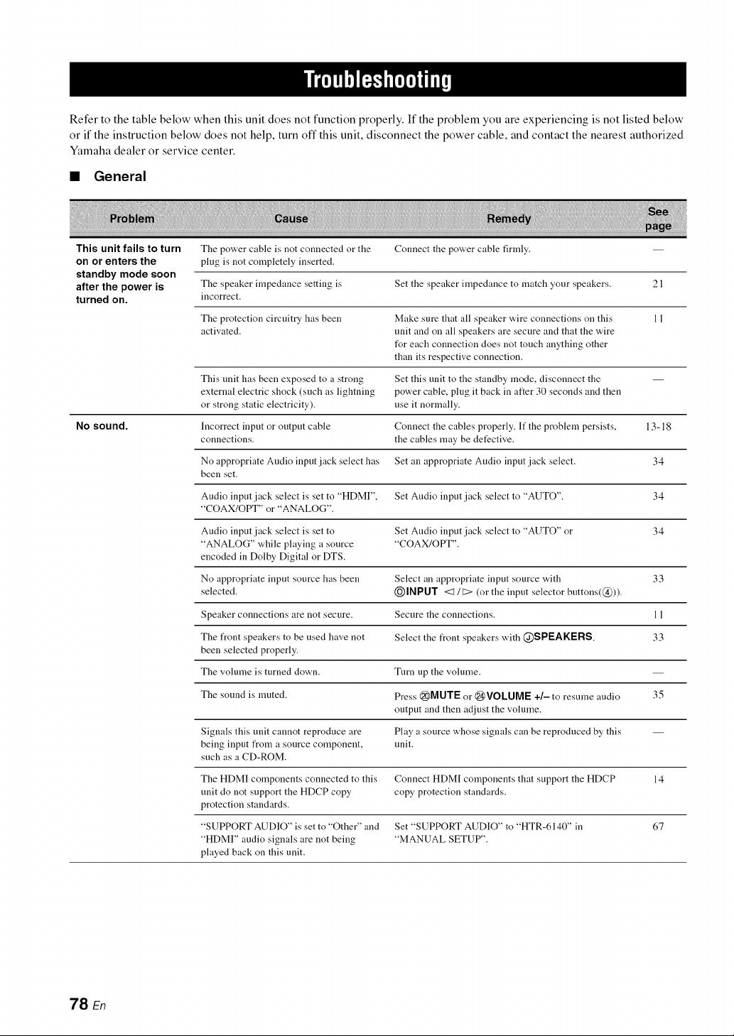
Refer to the table below when this unit does not function properly. If the problem you are experiencing is not listed below
or if the instruction below does not help, turn off this unit, disconnect the power cable, and contact the nearest authorized
Yamaha dealer or service center.
• General
This unit fails to turn The power cable is not connected or the Connect the power cable firmly.
on or enters the plug is not completely inserted.
standby mode soon
afterthe poweris The speaker impedance setting is Set the speaker impedance to match your speakers. 21
turned on. incorrect.
The protection circuitry has been Make sure that all speaker wire connections on this 1 1
activated, unit and on all speakers are secure and that the wire
for each connection does not touch anything other
than its respective connection.
This unit has been exposed to a strong Set this unit to the standby mode, disconnect the --
external electric shock (such as lightning power cable, plug it back in after 30 seconds and then
or strong static electricity), use it normally.
No sound. Incorrect input or output cable Connect the cables properly. If the problem persists, 13-18
connections, the cables may be detective.
No appropriate Audio input jack select has Set an appropriate Audio input jack select. 34
been set.
Audio input jack select is set to "HDMI", Set Audio input jack select to "AUTO". 34
"COAX/OPT' or "ANALOG".
Audio input jack select is set to Set Audio input jack select to "AUTO" or 34
"ANALOG" while playing a source "COAX/OPT".
encoded in Dolby Digital or DTS.
No appropriate input source has been Select an appropriate input source with 33
selected. I_)INPUT <:1 / C> (or the input selector buttons(@)).
Speaker connections are not secure. Secure the connections. 11
The front speakers to be used have not Select the front speakers with @SPEAKERS. 33
been selected properly.
The volume is turned clown. Turn up the volume.
The sound is muted. Press @MUTE or @VOLUME +/- to resume audio 35
output and then adjust the volume.
Signals this unit cannot reproduce are Play a source whose signals can be reproduced by this --
being input from a source component, unit.
such as a CD-ROM.
The HDMI components connected to this Connect HDMI components that support the HDCP 14
unit do not support the HDCP copy copy protection standards.
protection standards.
"SUPPORT AUDIO" is set to "Other" and Set "SUPPORT AUDIO" to "HTR-6140" in 67
"HDMI" audio signals are not being "MANUAL SETUP".
played back on this unit.
78 En
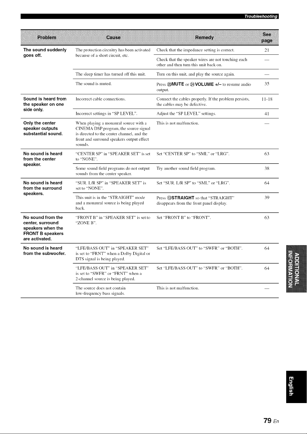
The sound suddenly
goes off.
The protection circuitry has been activated
because of a short circuit, etc.
Check that the impedance setting is correct.
Check that the speaker wires are not touching each
other and then turn this unit back on.
21
The sleep timer has turned off this unit. Turn on this unit, and play the source again.
The sound is muted. Press _MUTE or @VOLUME +/- to resume audio 35
output.
Sound is heard from Incorrect cable connections. Connect the cables properly. If the problem persists, 11-18
the speaker on one the cables may be defective.
side only.
Incorrect settings in "SP LEVEL". Adjust the "SP LEVEL" settings. 41
Only the center When playing a monaural source with a This is not malfimction.
speaker outputs CINEMA DSP program, the source signal
substantial sound, is directed to the center channel, and the
front and surround speakers output effect
sounds.
No sound is heard "CENTER SP" in "SPEAKER SET" is set Set "CENTER SP" to "SML" or "LRG". 63
from the center to "NONE".
speaker.
Some sound field programs do not output Try another sound field program. 38
sounds from the center speaker.
No sound is heard "SUR. L/R SP" in "SPEAKER SET" is Set "SUR. L/R SP" to "SML" or "LRG". 64
from the surround set to "NONE".
speakers.
This unit is in the "STRAIGHT" mode Press @STRAIGHT so that "STRAIGHT" 39
and a monaural source is being played disappears from the front panel display.
back.
No sound from the "FRONT B" in "SPEAKER SET" is set to Set "FRONT B" to "FRONT". 63
center, surround "ZONE B".
speakers when the
FRONT B speakers
are activated.
No sound is heard "LFE/BASS OUT" in "SPEAKER SET" Set "LFE/BASS OUT" to "SWFR" or "BOTH". 64
from the subwoofer, is set to "FRNT" when a Dolby Digital or
DTS signal is being played.
"LFE/BASS OUT" in "SPEAKER SET" Set "LFE/BASS OUT" to "SWFR" or "BOTH". 64
is set to "SWFR" or "FRNT" when a
2-channel source is being played.
The source does not contain This is not malfimction.
low-frequency bass signals.
79 En
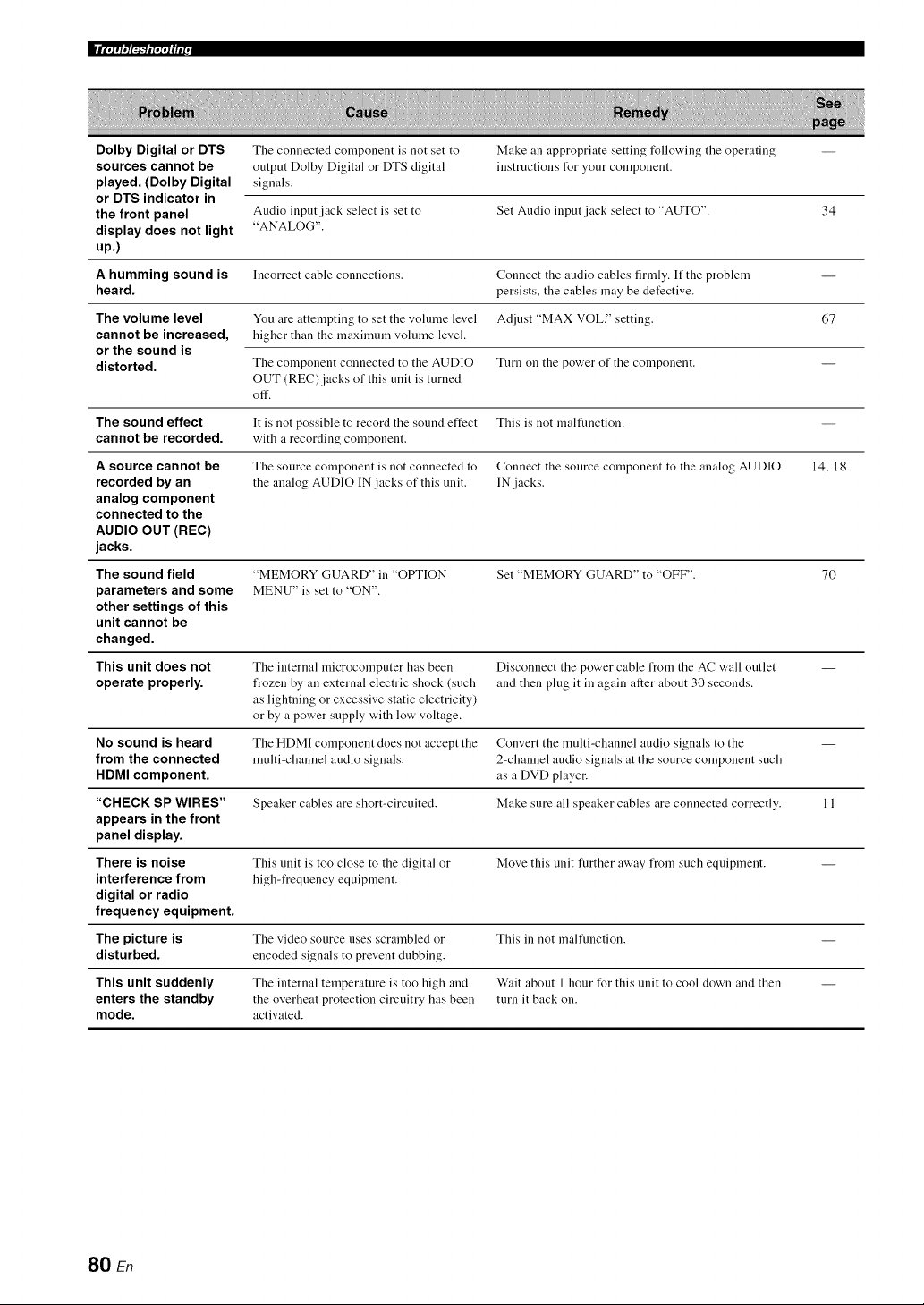
|J_ETT_IIIEr.
Dolby Digital or DTS Tile connected component is not set to Make an appropriate setting follo'_,ing tile operating --
sources cannot be output Dolby Digital or DTS digital instructions Ibr your component.
played. (Dolby Digital signals.
or DTS indicator in
the front panel Audio input jack select is set to Set Audio input jack select to "AUTO". 34
display does not light "ANALOG".
up.)
A humming sound is Incorrect cable conuections. Connect the audio cables firmly. If the problem --
heard, persists, the cables may be detective.
The volume level You are attempting to set the volume level Adjust "MAX VOL." setting. 67
cannot be increased, higher than the maximum vohnne level.
or the sound is
distorted. Tile compouent connected to tile AUDIO Turn on tile power of tile compouent. --
OUT (REC) jacks of this unit is turned
off.
The sound effect It is not possible to record the sound effect This is not malfimction.
cannot be recorded, with a recording component.
A source cannot be The source component is not connected to Connect the source component to the analog AUDIO 14, 18
recorded by an the analog AUDIO IN jacks of this unit. IN jacks.
analog component
connected to the
AUDIO OUT (REC)
jacks.
The sound field
parameters and some
other settings of this
unit cannot be
changed.
"MEMORY GUARD" in "OPTION
MENU" is set to "ON".
Set "MEMORY GUARD" to "OFF". 70
This unit does not The internal microcomputer has been Disconnect the power cable from the AC wall outlet --
operate properly, frozen by an external electric shock (such and then plug it in again after about 30 seconds.
as lightning or excessive static electricity)
or by a power supply with low voltage.
No sound is heard The HDMI component does not accept the Convert the multi-channel audio signals to the --
from the connected multi-channel audio signals. 2-channel audio signals at the source component such
HDMI component, as a DVD player.
"CHECK SP WIRES" Speaker cables are short-circuited. Make sure all speaker cables are connected correctly. 11
appears in the front
panel display.
There is noise This unit is too close to tile digital or Move this unit further away from such equipment. --
interference from high-frequency equipment.
digital or radio
frequency equipment.
The picture is The video source uses scrambled or This in not malfuuction.
disturbed, encoded signals to prevent dubbing.
This unit suddenly The internal temperature is too high and Wait about 1 hour for this unit to cool down and then --
enters the standby the overheat protection circuitry has been turn it back on.
mode. activated.
80 En
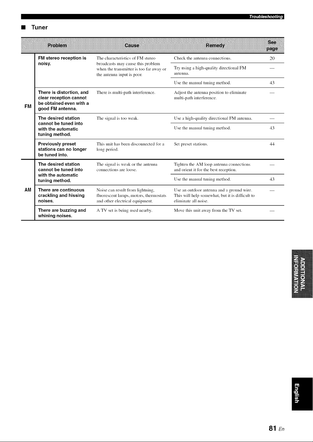
• Tuner
FM
FM stereo reception is
noisy.
There is distortion, and
clear reception cannot
be obtained even with a
good FM antenna.
The desired station
cannot be tuned into
with the automatic
tuning method.
The characteristics of FM stereo
broadcasts may cause this problem
when the transmitter is too far away or
the antenna input is poor.
There is multi-path interference.
The signal is too weak.
Check the antenna connections. 20
Try using a high-quality directional FM
antenna.
Use the manual tuning method. 43
Adjust the antenna position to eliminate
multi-path interference.
Use a high-quality directional FM antenna.
Use the manual tuning method. 43
Previously preset This unit has been disconnected t_r a Set preset stations. 44
stations can no longer long period.
be tuned into.
The desired station Tile signal is weak or tile antenna Tighten tile AM loop antenna connections --
cannot be tuned into connections are loose, and orient it for the best reception.
with the automatic
tuning method. 43
Use the manual tuning method.
AM There are continuous Noise can result from lightning, Use an outdoor antenna and a ground wire.
crackling and hissing fluorescent lamps, motors, thermostats This will help somewhat, but it is difficult to
noises, and other electrical equipment, eliminate all noise.
There are buzzing and A TV set is being used nearby. Move this unit away from the TV set. --
whining noises.
I
81 En
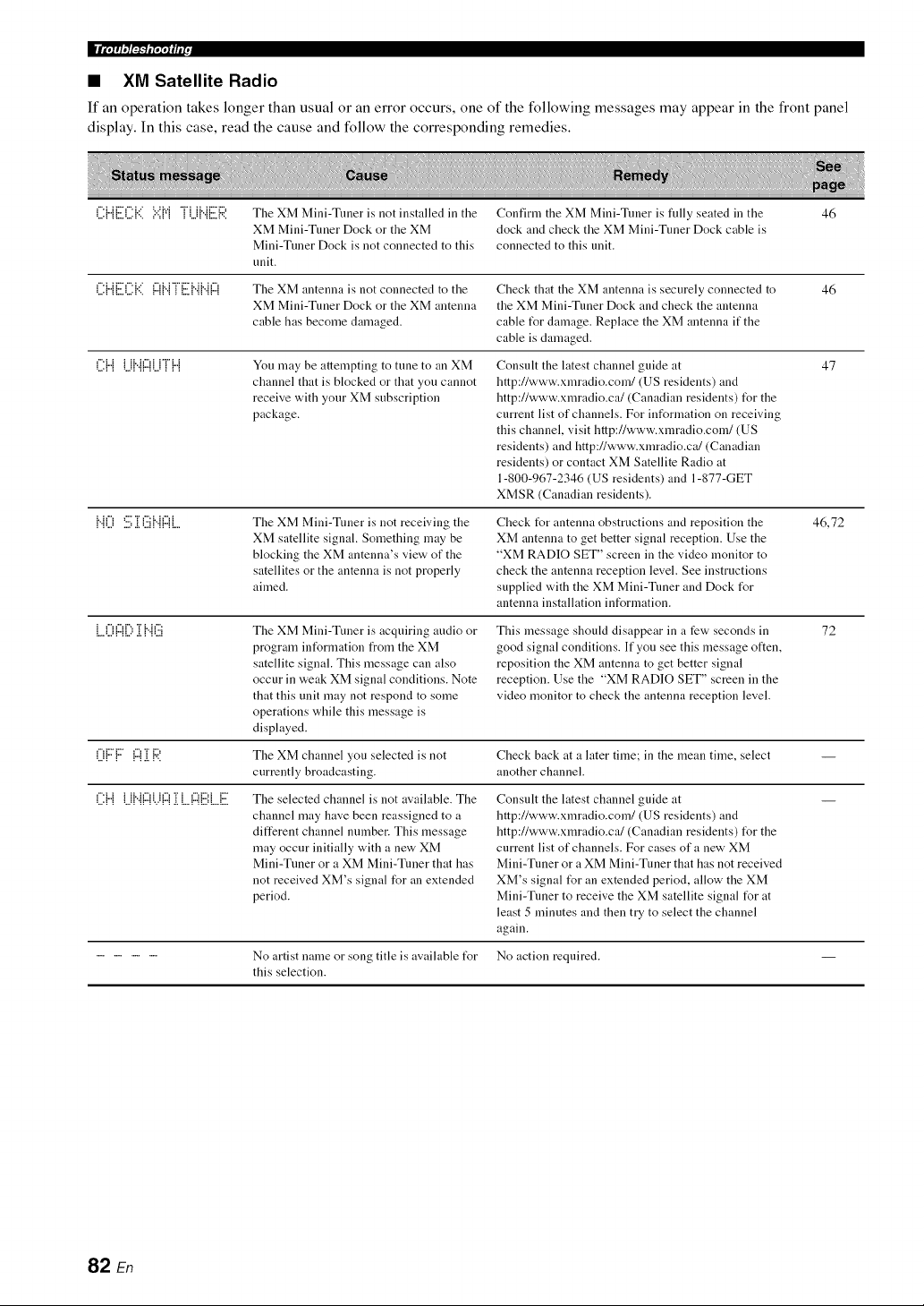
• ×M Satellite Radio
If an operation takes kruger than usual or an error occurs, one of the following messages may appear in the front pane]
display. In this case, read the cause and follow the corresponding remedies.
('.i:{"{[:.i)i'.i:{'::i':.:'{v{'iU{".{[:.ilR The XM Mini-Tuner is not installed in the Confirm the XM Mini-Tuner is fully seated in the 46
XM Mini-Tuner Dock or the XM dock and check the XM Mini-Tuner Dock cable is
Mini-Tuner Dock is not connected to this connected to this unit.
unit.
('.i:{"{[:.i)i'.i:{'::i{:::{{".{m[:.ii{".{{".{{:::{The XM antenna is not connected to the Check that the XM autelma is securely connected to 46
XM Mini-Tuner Dock or the XM antenna the XM Mini-Tuner Dock and check the antenna
cable has become dalnaged, cable I_r damage. Replace the XM antenna if the
cable is damaged.
('.i:{"{U{"{I:::IUT{"{ You may be attempting to tune to an XM Consult the latest chalmel guide at 47
channel that is blocked or that you cannot http://www.xmradio.com/(US residents) and
receive with your XM subscription http://www.xlnradio.ca/(Canadian residents) I_r the
package, current list of channels. For iuformation on receiving
this chalmel, visit http://www.xlnradio.cona/(US
residents) and http://www.xlnradio.ca/(Canadian
residents) or contact XM Satellite Radio at
1-800-967-2346 (US residents) and 1-877-GET
XMSR (Canadian residents).
{"{() '.i:.i;]i(:.ii{"{{:::{[ The XM Mini-Tuner is not receiving the Check I_r antenna obstructions and reposition the 46,72
XM satellite signal. Something lnay be XM antenna to get better signal reception. Use the
blocking the XM antenna's view of the "XM RADIO SET" screen in the video lnonitor to
satellites or the antenna is not properly check the antenna reception level. See instructions
aimed, supplied with the XM Mini-Tuner and Dock I_r
antenna installation information.
L.()A[) ]i{..{(:.ii The XM Mini-Tuner is acquiring audio or This message shoukt disappear in a few seconds in 72
prograln iutUrmation from the XM good signal conditions. If you see this lnessage otten
satellite signal. This message can also reposition the XM antenna to get better signal
occur in weak XM signal conditions. Note reception. Use the "XM RADIO SET" screen in the
that this unit may not respond to some video monitor to check the antenna reception level.
operations while this message is
displayed.
()F{:::" {:::1]i {:ii'. The XM channel you selected is not Check back at a later time; in the mean time, select --
currently broadcasting, another channel.
L:{"{ U{"{{"{i...i{"{.[ L.{"{{:'.:',L.{: The selected channel is not available. The Consult the latest chalmel guide at
channel may have been reassigned to a http://www.xmradio.com/(US residents) and
different channel number. This message http://www.xlnradio.ca/(Canadian residents) IUr the
may occur initially with a new XM current list of channels. For cases of a new XM
Mini-Tuner or a XM Mini-Tuner that has Mini-Tuner or a XM Mini-Tuner that has not received
not received XM's signal for an extended XM's signal IUr an extended period, allow the XM
period. Mini-Tuner to receive the XM satellite signal IUr at
least 5 minutes and then try to select the channel
again.
................ No artist name or song title is available I_r No action required.
this selection.
82 En
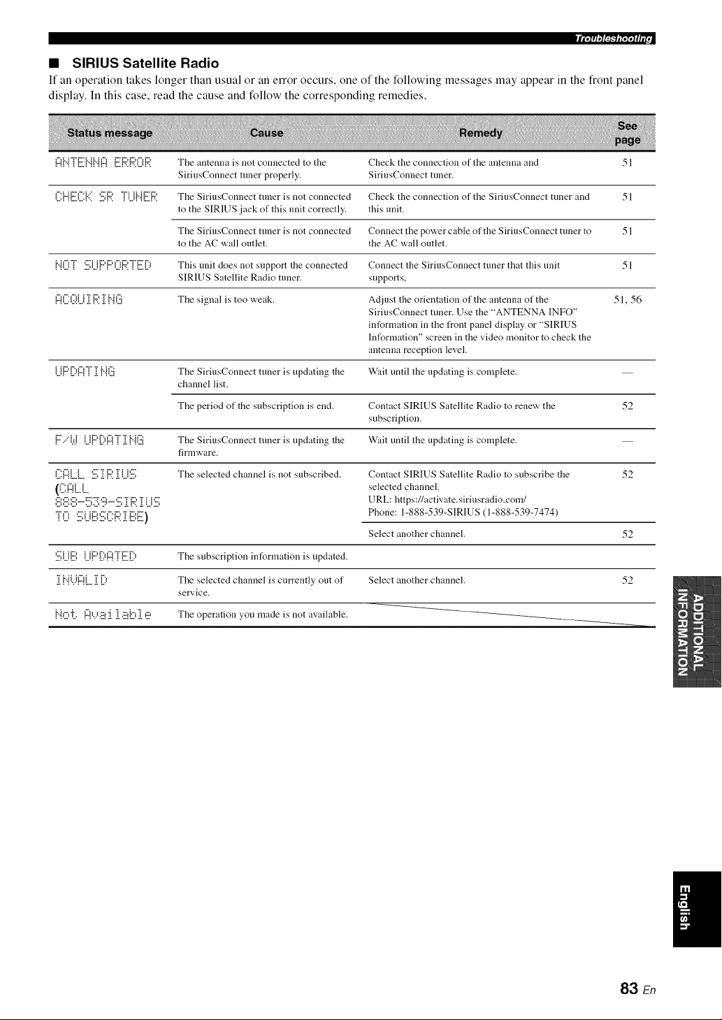
• SIRIUS Satellite Radio
If an operation takes longer than usual or an error occurs, one of the following messages may appear in the front panel
display. In this case, read the cause and follow the corresponding remedies.
{:::{{...{r[:.i]...{{...{{:::{[:.i]:4,.{:4,.(){::ii The antenna is not connected to the Check the connection of the antenna and 51
SiriusConnect tuner properly. SiriusConnect tuner.
('.i:{"{[:.i)]{'::i=.i:.i;R.'rLi{..{[:.i]:4'. The SiriusConnect tuner is not connected Check the connection of the SiriusConnect tuner and 51
to the SIRIUS jack of this unit correctly, this unit.
The SiriusConnect tuner is not connected Connect the power cable of the SiriusConnect tuner to 51
to the AC wall outlet, the AC wall outlet.
i..i()r :.i:.iJ..ii:::,i:::,()i::?.rii:.i]i) This unit does not support the connected Connect the SiriusConnect tuner that this unit 51
SIRIUS Satellite Radio tuner, supports,
l:::{('.X)i..j]i{:;?.]i {"{(:.ii The signal is too weak. Adjust the orientation of the antenna of the 51, 56
SiriusConnect tuner. Use the "ANTENNA INFO"
information in the front panel display or "SIRIUS
Information" screen in the video monitor to check the
antenna reception level.
Li{:::'[)I:::IT]i {"{(iii The SiriusConnect tuner is updating the Wait until the updating is complete. --
channel list.
The period of the subscription is end. Contact SIRIUS Satellite Radio to renew the 52
subscription.
1"."'W Li{"'{.){...{! .[{"{U The SiriusConnect tuner is updating the Wait until the updating is complete.
firmware.
r'.c'_i i ,:::"Ti:::,"ri i,:::" The selected channel is not subscribed. Contact SIRIUS Satellite Radio to subscribe the 52
((ii:!Z!L.L. selected channel.
@i:.iiii:.ii"-{:.:.!;ii:.!;'ii;i'°''.i:.i;ii.i{:;?.ii.ii..i'.i'.i; URL: https://activate, siriusradio.com/
'r() SLi[ii',Si[:{:;;:i[[ii',E) Phone: 1-888-539-SIRIUS (1-888-539-7474)
Select another channel.
".,,,i ii.,,1 1 ii.,,'i ii.,,i i i.,, i i
"ri, il h%i "r r',,
,!, ! "i :,..q"i !,., ,!, !,..:
:,:,,.,:. :: ....... : ,,.:,. : ,,.
: :,,., ,., : :v .,.: ,:, ,:, ,,.::,., ,:, ,,.
52
The subscription information is updated.
The selected channel is currently out of Select another channel. 52
service.
The operation you made is not available.
83 En
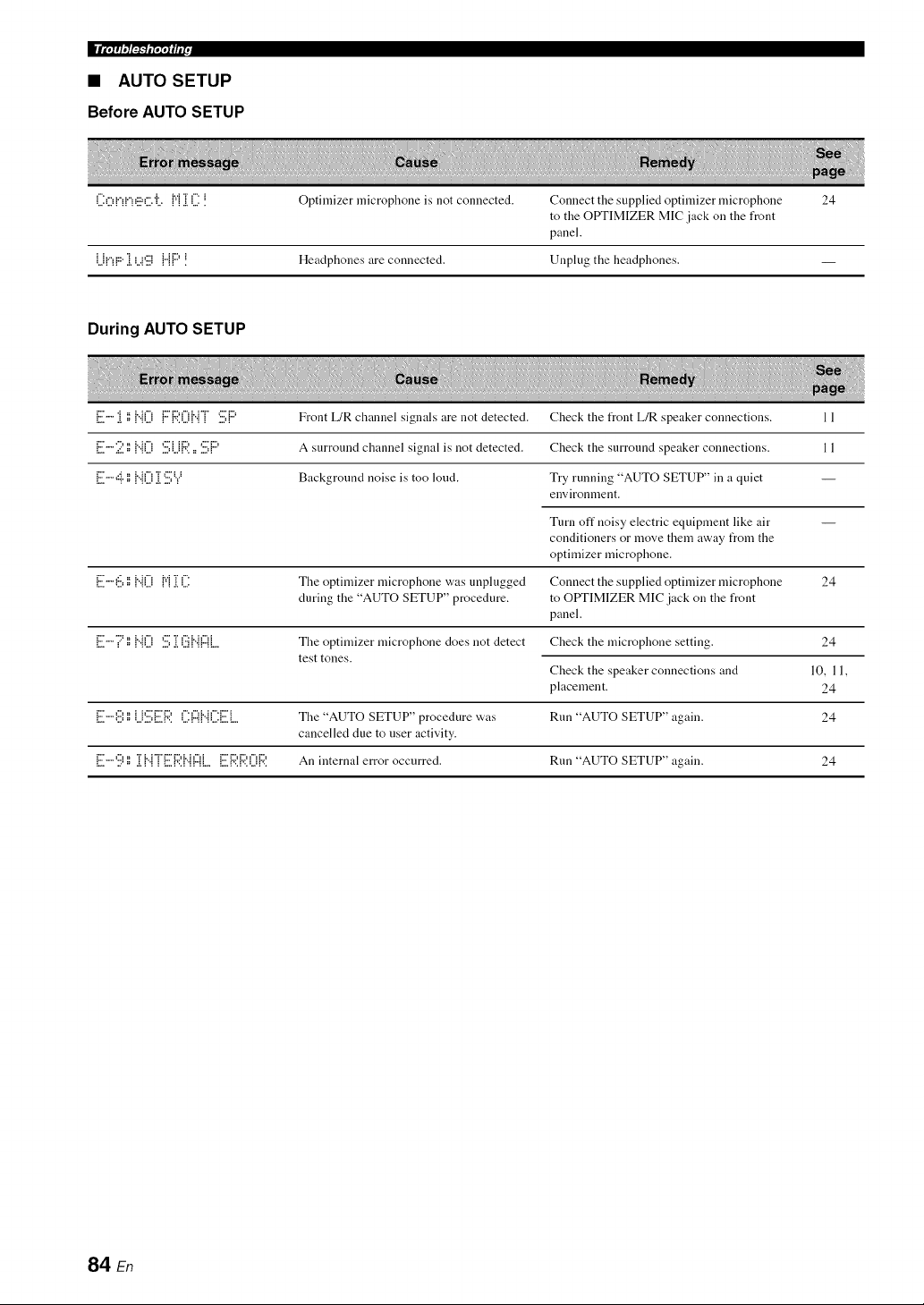
ImEigO_F-NE27!_IIE(,
• AUTO SETUP
Before AUTO SETUP
('.i:O!"!!"!_!:.!:C.'iL.{':'{]i('.i:! Optimizer microphone is not connected. Connect the supplied optimizer microphone 24
to the OPTIMIZER MIC jack on the front
panel.
U!"!F:"1 L.)g i"ii:::'! Headphones are connected. Unplug the headphones. --
During AUTO SETUP
{i:.ii""i i) {"i0 {:::i:;?.0i".H '.i:.i;i:::' Front L/R chalmel signals are not detected. Check the front L/R speaker connections. 11
ii:.ii'"2','=i"i0 '.i:.i;i..ji::?.=='.i:.i;i:" A surround channel signal is not detected. Check the surround speaker connections. 11
[iii""'::i"','=i"i0 i['.iii;Y Background noise is too loud. Try running "AUTO SETUP" in a quiet --
environnlent.
Turn off noisy electric equipment like air
conditioners or move them away from the
optimizer microphone.
E"'i:.:.i,i:,{"{0 {"{]i ('.i: The optimizer microphone was nnplugged Connect the supplied optimizer microphone 24
during the "AUTO SETUP" procedure, to OtYI'IMIZER MIC jack on the front
panel.
[:.ii""i::'','={"{0 '.i:.i;ii.i(:.ii{".{(ZlL. The optimizer microphone does not detect Check the microphone setting. 24
test tones.
10, 11,
24
24
Check the speaker connections and
placement.
[:.ii"",i:.i',i:,U'.i:.i:[:.i]::?.(.i:(z({".{(.i:[:.i]. The "AUTO SETUP" procedure was Run "AUTO SETUP" again.
cancelled due to user activity.
E""ii) ','=]i{"{T[:.i]::?.I"llZIL.[:.i]:,?.1::?.01:4'. An internal error occurred. Run "AUTO SETUP" again. 24
84 En
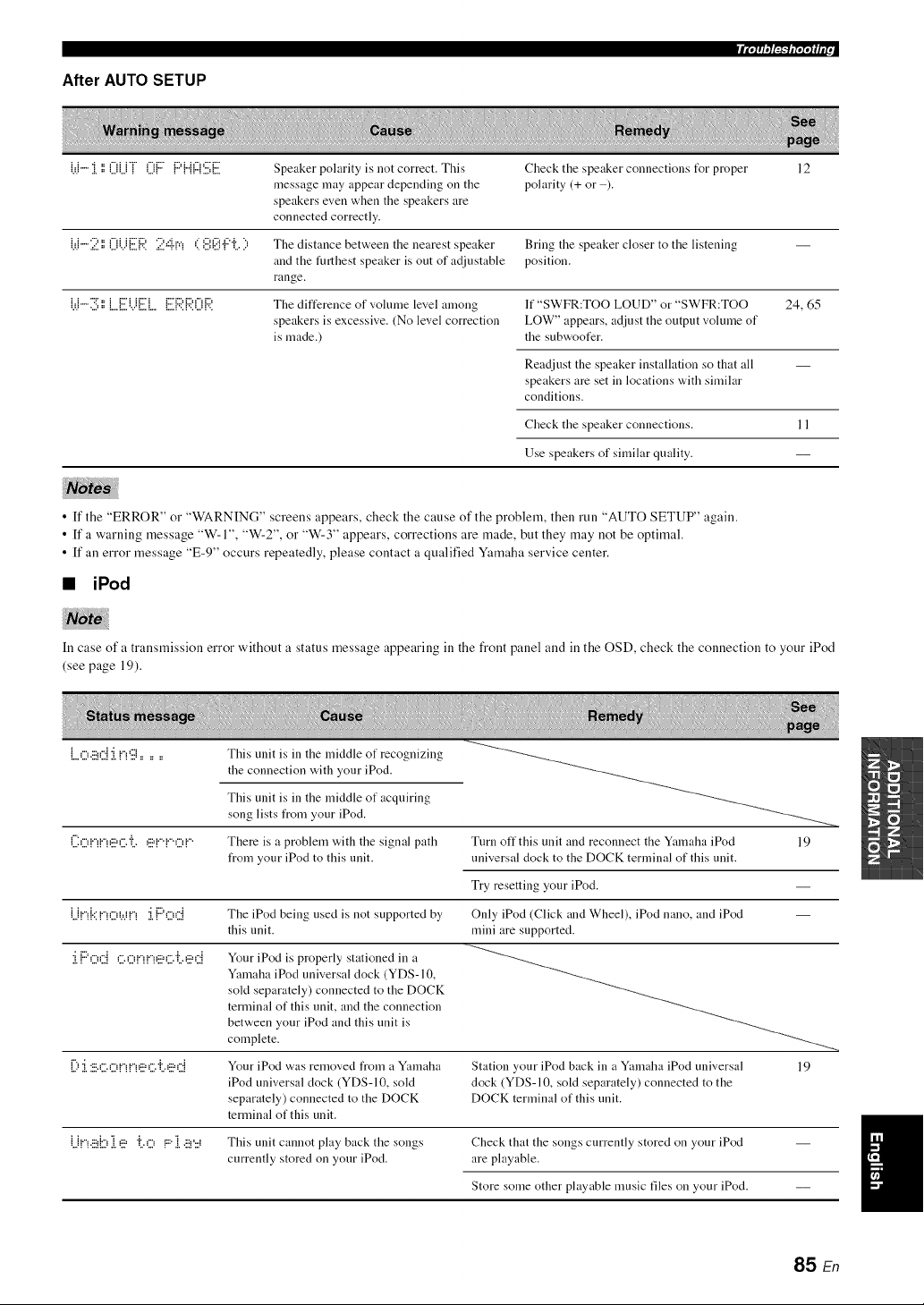
After AUTO SETUP
W"" i ',',0U"i" 0{ :7 {:::'{"{{z{'.i:.i;[i. Speaker polarity is not correct. This Check the speaker connections t_r proper 12
message may appear depending on the polarity (+ or ).
speakers even when the speakers are
connected correctly.
{._.b"'2',',0i.)[:.i]::4'. 2,::i.rq < ',i.i',@!:"il.i:, The distance between the nearest speaker Bring the speaker closer to the listening
and the furthest speaker is out of adjustable position.
range.
W"'3 ',',L.Ei.)[:.i]... [:.i]:4'.{:,?.0R The difference of volume level among If "SWFR:TOO LOUD" or "SWFR:TOO 24, 65
speakers is excessive. (No level correction LOW" appears, adjust the output volume of
is made.) the subwoofer.
Readjust the speaker installation so that all
speakers are set in locations with similar
conditions.
Check the speaker connections. 11
Use speakers of similar quality.
• If the "ERROR" or "WARNING" screens appears, check the cause of the problem, then run "AUTO SETUP" again.
• If a warning message "W-1", "W-2", or "W-3" appears, corrections are made, but they may not be optimal.
• If an error message "E-9" occurs repeatedly, please contact a qualified Yamaha service center.
• iPod
In case of a transmission error without a status message appearing in the front panel and in the OSD, check the connection to your iPod
(see page 19).
L.o.!_,::i:i!_g......
i"" ,.-, :.-, :.-, ,.-, ,.- ,i. ..-, :.-, :.-, ,.-, :.,.,
=..,:..q _ _::2":.., :., =:2"_ _ =..q
•...: ::..: :....v..: : ._: .......:
::...:::.: : :::.::.::...:: : :...::.:
.:,: .......: ........: :: :................:
: : : ....: : ::.::.::...:: : :...:: .:
:...._ ............: :: :................:
U!<_bi,!_=i>::,!:::i,!_'::_
This unit is in the middle of recognizing
the connection with your iPod.
This unit is in the middle of acquiring
song lists from your iPod.
There is a problem with the signal path
from your iPod to this unit.
Tnrn off this unit and reconnect the Yamaha iPod 19
universal dock to the DOCK terminal of this unit.
Try resetting your iPod.
The iPod being used is not supported by
this unit.
Your iPod is properly stationed in a
Yamaha iPod universal clock (YDS-10,
sold separately) connected to the DOCK
terminal of this unit, and the connection
between your iPod and this unit is
complete.
Your iPod was removed from a Yamaha
iPod universal clock (YDS-10, sold
separately) connected to the DOCK
terminal of this unit.
Only iPod (Click and Wheel), iPod nano, and iPod
mini are supported.
Station your iPod back in a Yamaha iPod universal 19
dock (YDS-10, sold separately) connected to the
DOCK terminal of this unit.
This unit cannot play back the songs
currently stored on your iPod.
Check that the songs currently stored on your iPod
are playable.
Store some other playable music files on your iPod.
85 En
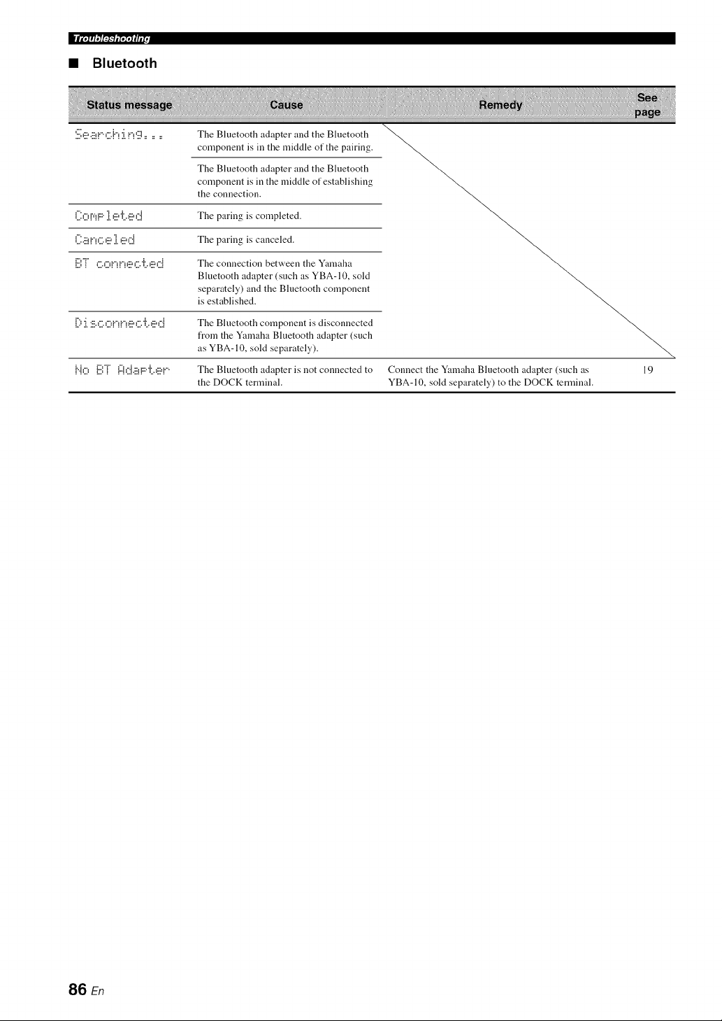
• Bluetooth
S,!:_,.!:_!",::.h:ing ......
The Bluetooth adapter and the Bluetooth
component is ill the middle of the pairing.
The Bluetooth adapter and the Bluetooth
component is in the middle of establishing
the connection.
('.i:OV!F:"1 _!:.!='ii._!:.!=d The paring is completed.
('.I:.!:.!H"!_:"._!:.!=1 _!:.!=_:'.:i The paring is canceled.
:.,.. -:- : :
_...:_ ," ,",v',v',,:::=,""r ,:::=,"._ The connection between the Yamaha
Bluetooth adapter (such as YBA- 10, sold
separately) and the Bluetooth component
is established.
[) :[:!:',_:",O!"H"!_!:'=_:",'i',_!:'=d The Bluetooth component is disconnected
from the Yamaha Bluetooth adapter (such
as YBA- 10, sold separately).
;. ; .,. r":"r" 1": .A ........ i.......
!"!u !:::,! !"!L:!.::!!""L._::=!"" The Bluetooth adapter is not connected to
the DOCK terminal.
Connect the Yamaha Bluetooth adapter (such as 19
YBA-10, sold separately) to the DOCK terminal.
86 En
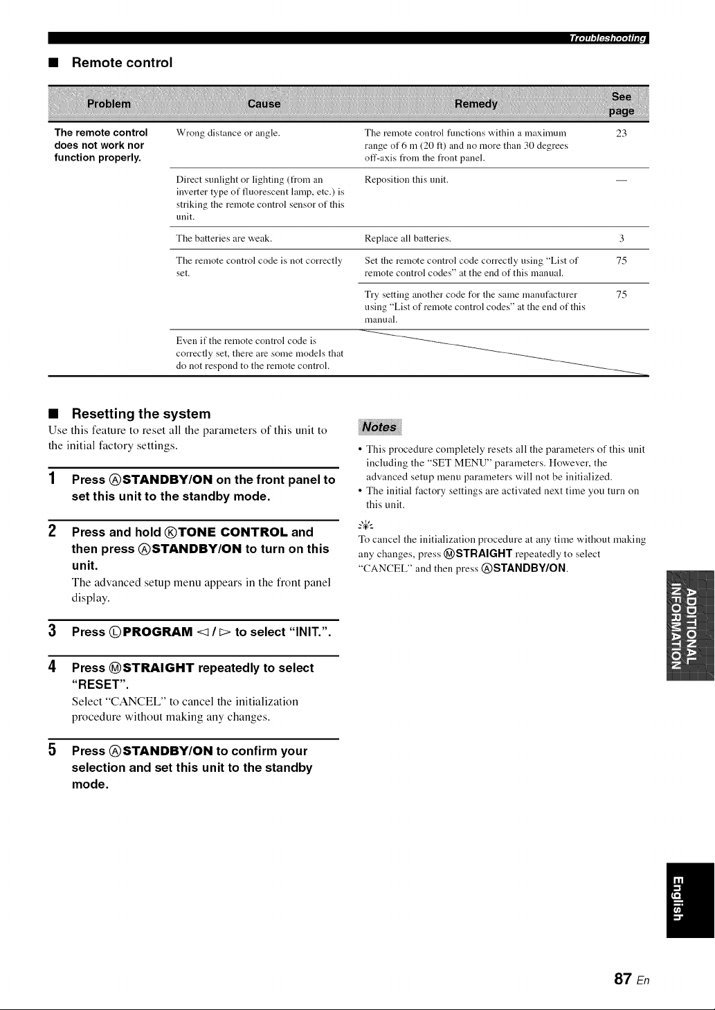
_l'g_f_fffP
• Remote control
The remote control Wrong distance or angle. Tile remote control functions "adthin a maximnnl 23
does not work nor range of 6 m (20 It) and no more than 30 degrees
function properly, off-axis t_om the front panel.
Direct sunlight or lighting (from an Reposition this unit.
inverter type of fluorescent lamp, etc.) is
striking the remote control sensor of this
unit.
The batteries are weak. Replace all batteries. 3
The remote control code is not correctly Set the remote control code correctly using "List of 75
set. remote control codes" at the end of this manual.
Try setting another code for the same manufacturer
using "List of remote control codes" at the end of this
nlanual.
Even if the remote control code is
correctly set, there are some models that
do not respond to the remote control.
75
• Resetting the system
Use this feature to reset all the parameters of this unit to
the initial factory settings.
1 Press @STANDBY/ON on the front panel to
set this unit to the standby mode.
Press and hold @TONE CONTROL and
then press @STANDBY/ON to turn on this
unit.
The advanced setup menu appears in the front panel
display.
3 Press @PROGRAM <1/I> to select "INIT.".
4 Press @STRAIGHT repeatedly to select
"RESET",
Select "CANCEL" to cancel the initialization
procedure without making any changes.
5 Press @STANDBY/ON to confirm your
selection and set this unit to the standby
mode.
• This procedure completely resets all the parameters of this unit
including the "SET MENU" parameters. However, the
advanced setup menu parameters will not be initialized.
• The initial factory settings are activated next time you turn on
this unit.
To cancel the initialization procedure at any time without making
any changes, press (_STRAIGHT repeatedly to select
"CANCEL" and then press @STANDBY/ON
87 En
• CINEMA DSP
Since the Dolby Surround and DTS systems were
originally designed for use in movie theaters, their effect
is best felt in a theater having many speakers designed for
acoustic effects. Since home conditions, such as room
size, wall material, number of speakers, and so on, can
differ so widely, it is inevitable that there are differences in
the sound heard. Based on a wealth of actually measured
data, Yamaha CINEMA DSP uses Yamaha original sound
field technology to combine Dolby Pro Logic, Dolby
Digital and DTS systems to provide the audiovisual
experience of a movie theater in the listening room of your
own home.
• Component video signal
With the component video signal system, the video signal
is separated into the Y signal for the luminance and the PB
and Pr signals for the chrominance. Color can be
reproduced more faithfully with this system because each
of these signals is independent. The component signal is
also called the "color difference signal" because the
luminance signal is subtracted from the color signal. A
monitor with component input jacks is required in order to
output component signals.
• Composite video signal
With the composite video signal system, the video signal
is composed of three basic elements of a video picture:
color, brightness and synchronization data. A composite
video jack on a video component transmits these three
elements combined.
• Dolby Digital
Dolby Digital is a digital surround sound system that gives
you completely independent multi-channel audio. With 3
front channels (front LIR and center), and 2 surround
stereo channels, Dolby Digital provides 5 full-range audio
channels. With an additional channel especially for bass
effects, called LFE (Low Frequency Effect), the system
has a total of 5.1 -channels (LFE is counted as 0.1
channel). By using 2-channel stereo for the surround
speakers, more accurate moving sound effects and
surround sound environment are possible than with Dolby
Surround. The wide dynamic range from maximum to
minimum volume reproduced by the 5 full-range channels
and the precise sound orientation generated using digital
sound processing provide listeners with unprecedented
excitement and realism. With this unit, any sound
environment from monaural up to a 5.1-channel
configuration can be freely selected for your enjoyment.
• Dolby Pro Logic II
Dolby Pro Logic II is an improved technique used to
decode vast numbers of existing Dolby Surround sources.
This new technology enables a discrete 5-channel
playback with 2 front left and right channels, 1 center
channel, and 2 surround left and right channels instead of
only 1 surround channel for conventional Pro Logic
technology. There are three modes available: "Music
mode" for music sources, "Movie mode" for movie
sources and "Game mode" for game sources.
• Dolby Surround
Dolby Surround uses a 4-channel analog recording system
to reproduce realistic and dynamic sound effects: 2 front
left and right channels (stereo), a center channel for dialog
(monaural), and a surround channel for special sound
effects (monaural). The surround channel reproduces
sound within a narrow frequency range. Dolby Surround is
widely used with nearly all video tapes and laser discs,
and in many TV and cable broadcasts as well. The Dolby
Pro Logic decoder built into this unit employs a digital
signal processing system that automatically stabilizes the
volume on each channel to enhance moving sound effects
and directionality.
• DTS Digital Surround
DTS digital surround was developed to replace the analog
soundtracks of movies with a 5.1-channel digital sound
track, and is now rapidly gaining popularity in movie
theaters around the world. DTS, Inc. has developed a
home theater system so that you can enjoy the depth of
sound and natural spatial representation of DTS digital
surround in your home. This system produces practically
distortion-free 5. l-channel sound (technically, left, right
and center channels, 2 surround channels, plus an LFE 0.1
channel as a subwoofer, for a total of 5.1 -channels).
88 En
• HDMI
HDMI (High-Definition Multimedia Interface) is the first
industry-supported, uncompressed, all-digital audio/video
interface. Providing an interface between any source (such
as a set-top box or AV receiver) and an audio/video
monitor (such as a digital television), HDMI supports
standard, enhanced or high-definition video as well as
multi-channel digital audio using a single cable. HDMI
transmits all ATSC HDTV standards and supports
8-channel digital audio, with bandwidth to spare to
accommodate future enhancements and requirements.
When used in combination with HDCP (High-bandwidth
Digital Content Protection), HDMI provides a secure
audio/video interface that meets the security requirements
of content providers and system operators. For further
information on HDMI, visit the HDMI website at
"http://www.hdmi.org/".
• LFE 0.1 channel
This channel reproduces low-frequency signals. The
frequency range of this channel is from 20 Hz to 120 Hz.
This channel is counted as 0.1 because it only enforces a
low-frequency range compared to the full-range
reproduced by the other 5 channels in Dolby Digital or
DTS 5.l-channel systems.
• Neural Surround
Neural Surround '_' represents the latest advancement in
surround technology and has been adopted by XM
Satellite Radio for digital radio broadcast of surround
recordings and live events in surround sound. Neural
Surround '_ employs psychoacoustic frequency domain
processing which allows delivery of a more detailed sound
stage with superior channel separation and localization of
audio elements.
• PCM (Linear PCM)
Linear PCM is a signal format under which an analog
audio signal is digitized, recorded and transmitted without
using any compression. This is used as a method of
recording CDs and DVD audio. The PCM system uses a
technique for sampling the size of the analog signal per
very small unit of time. Standing for "Pulse Code
Modulation", the analog signal is encoded as pulses and
then modulated for recording.
• Sampling frequency and number of
quantized bits
When digitizing an analog audio signal, the number of
times the signal is sampled per second is called the
sampling frequency, while the degree of fineness when
converting the sound level into a numeric value is called
the number of quantized bits. The range of rates that can
be played back is determined based on the sampling rate,
while the dynamic range representing the sound level
difference is determined by the number of quantized bits.
In principle, the higher the sampling frequency, the wider
the range of frequencies that can be played back, and the
higher the number of quantized bits, the more finely the
sound level can be reproduced.
• SILENT CINEMA
Yamaha has developed a natural, realistic sound effect
DSP algorithm for headphones. Parameters for
headphones have been set for each sound field so that
accurate representations of all the sound field programs
can be enjoyed on headphones.
• Virtual CINEMA DSP
Yamaha has developed a Virtual CINEMA DSP algorithm
that allows you to enjoy DSP sound field surround effects
even without any surround speakers by using virtual
surround speakers. It is even possible to enjoy Virtual
CINEMA DSP using a minimal two-speaker system that
does not include a center speaker.
89 En
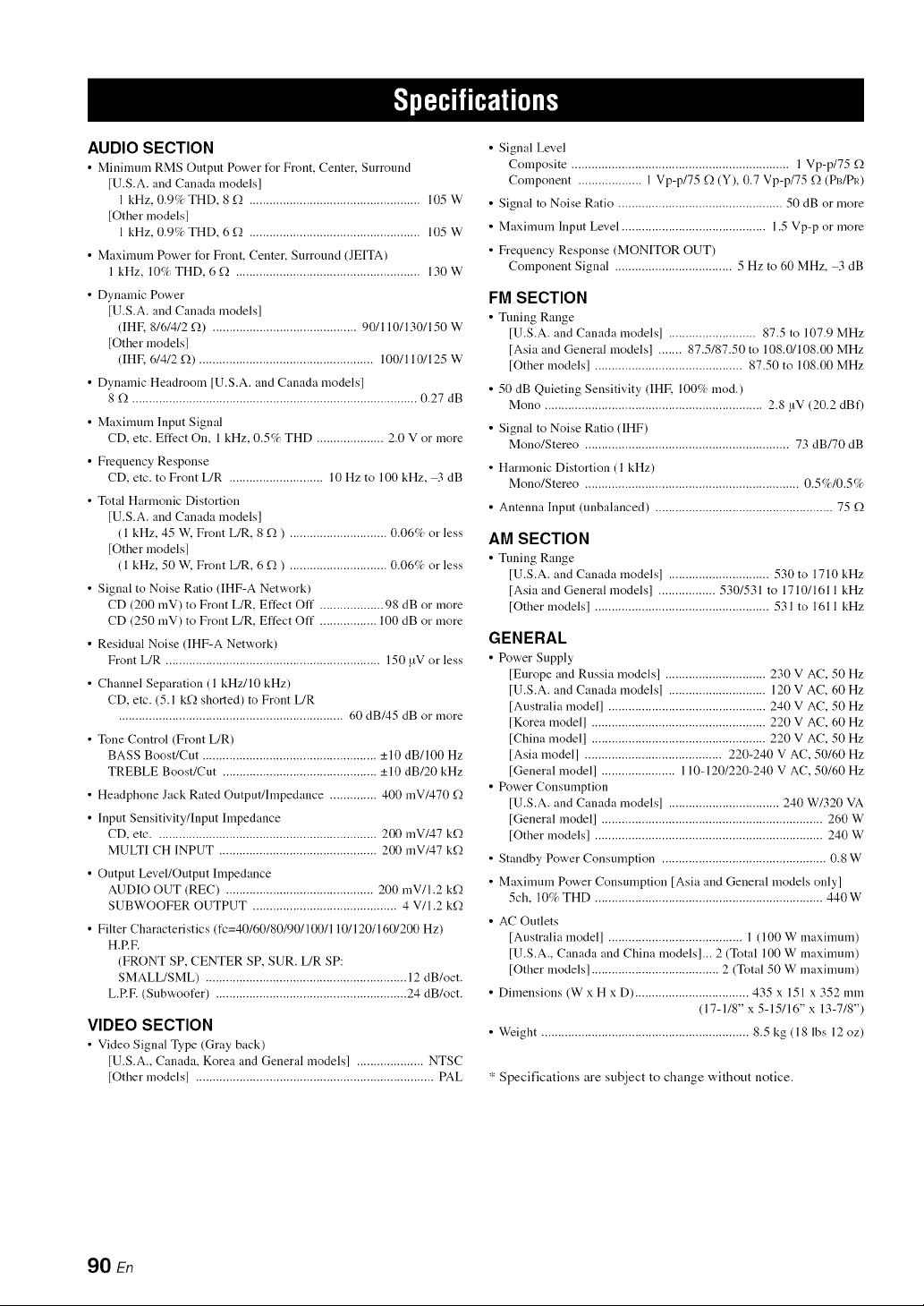
AUDIO SECTION
• Mininmm RMS Output Power t_r Front, Center, Surround
[U.S.A. and Canada modelsl
1 kHz, 0.9% THD, 8 f2 ................................................... 105 W
[Other models]
1 kHz, 0.9% THD, 6 f2 ................................................... 105 W
• Maxinmm Power t_r Front, Center, Surround (JEITA)
1 kHz, 10% THD, 6 f_ ....................................................... 130W
• Dynamic Power
[U.S.A. and Canada models]
(IHR 8/6/4/2 f2) ........................................... 90/110/130/150 W
[Other models]
(IHE (,/4/2 f2) .................................................... 100/110/125 W
• Dynamic Headroom [U.S.A. and Canada models]
8 f), ..................................................................................... 0.27 dB
• Maximum Input Signal
CD, etc. Effect On, 1 kHz, 0.5% THD .................... 2.0 V or more
• Frequency Response
CD, etc. to Front L/R ............................ 10 Hz to 100 kHz, 3 dB
• Total Harmonic Distortion
[U.S.A. and Canada models]
( 1 kHz, 45 W. Front L/R, 8 f,) ) ............................. 0.06% or less
[Other models]
(1 kHz, 50 W, Front L/R, 6 f,) ) ............................. 0.06% or less
• Signal to Noise Ratio (IHF-A Network)
CD (200 mV) to Front L/R, Effect Off ................... 98 dB or more
CD (250 mV) to Front L/R, Effect Off ................. 100 dB or more
• Residual Noise (IHF-A Network)
Front L/R ................................................................ 150 _V or less
• Channel Separation (1 kHz/10 kHz)
CD, etc. (5.1 kf_ shorted) to Front L/R
................................................................... 60 dB/45 dB or more
• Tone Control (Front L/R)
BASS Boost/Cut .................................................... +10 dB/100 Hz
TREBLE Boost/Cut .............................................. _+10 dB/20 kHz
• Headphone Jack Rated Output/hnpedance .............. 400 mV/470 _Q
• Input Sensitivity/Input hnpedance
CD, etc .................................................................. 200 mV/47 k_Q
MULTI CH INPUT ............................................... 200 mV/47 k_Q
• Output Level/Output Impedance
AUDIO OUT (REC) ............................................ 200 mV/l.2 k_Q
SUBWOOFER OUTPUT ........................................... 4 V/1.2 k_Q
• Filter Characteristics (fc=40/60/80/90/100/110/120/160/200 Hz)
H.RE
(FRONT SP, CENTER SP, SUR. L/R SP:
SMALL/SML) ............................................................ 12 dB/oct.
L.RE (Subwoofer) ......................................................... 24 dB/oct.
VIDEO SECTION
• Video Signal Type (Gray back)
[U.S.A., Canada, Korea and General models] .................... NTSC
[Other models] ....................................................................... PAL
• Signal Level
Composite ................................................................. l Vp-p/75 f_
Component ................... 1 Vp-p/75 f_ (Y), 0.7 Vp-p/75 f_ (PI3/PI0
• Signal to Noise Ratio ................................................. 50 dB or more
• Maximum Input Level ........................................... 1.5 Vp-p or more
• Frequency Response (MONITOR OUT)
Component Signal ................................... 5 Hz to 60 MHz, 3 dB
FM SECTION
• Tuning Range
[U.S.A. and Canada models] .......................... 87.5 to 107.9 MHz
[Asia and General models] ....... 87.5/87.50 to 108.0/108.00 MHz
[Other models] ............................................ 87.50 to 108.00 MHz
• 50 dB Quieting Sensitivity (IHR 100% rood.)
Mono ................................................................. 2.8 !iV (20.2 dBf)
• Signal to Noise Ratio (IHF)
Mono/Stereo ............................................................. 73 dB/70 dB
• Harmonic Distortion (l kHz)
Mono/Stereo ................................................................ 0.5%/0.5%
• Antenna Input (unbalanced) ..................................................... 75 f_
AM SECTION
• Tuning Range
[U.S.A. and Canada models] .............................. 530 to 1710 kHz
[Asia and General models] ................. 530/531 to 1710/1611 kHz
[Other models] .................................................... 531 to 1611 kHz
GENERAL
• Power Supply
[Europe and Russia models] .............................. 230 V AC, 50 Hz
[U.S.A. and Canada models] ............................. 120 V AC, 60 Hz
[Australia model] ............................................... 240 V AC, 50 Hz
[Korea model] .................................................... 220 V AC, 60 Hz
[China model] .................................................... 220 V AC, 50 Hz
[Asia model] ......................................... 220-240 V AC, 50/60 Hz
[General model] ...................... 110-120/220-240 V AC, 50/60 Hz
• Power Consumption
[U.S.A. and Canada models] ................................. 240 W/320 VA
[General model] .................................................................. 260 W
[Other models] .................................................................... 240 W
• Standby Power Consumption ................................................. 0.8 W
• Maximum Power Consumption [Asia and General models only]
5ch, 10% THD .................................................................... 440W
• AC Outlets
[Australia model] ........................................ 1 (100 W maximum)
[U.S.A., Canada and China models]... 2 (Total 100 W maximum)
[Other models] ...................................... 2 (Total 50 W maximum)
• Dimensions (W x H x D) .................................. 435 x 151 x 352 mm
(17-1/8" x 5-15/16" x 13-7/8")
• Weight .............................................................. 8.5 kg (18 lbs 12 oz)
* Specifications are subject to change without notice.
90 En
• Symbols
<XM> - - -,
XM tuning status message .................
• Numerics
l SOUND MENU, Manual setup ........ 61
2 INPUT MENU, Manual setup .......... 61
2ch Stereo, Sound field program ......... 38
3 OPTION MENU ............................... 70
3 OPTION MENU, Manual setup ....... 62
5ch Stereo, Sound field program ......... 38
• A
A)DISPLAY SET, Option menu ......... 70
A)INPUT ASSIGNMENT,
Input menu .........................................
A)SPEAKER SET, Sound menu ......... 63
A.DELAY, Audio settings ................... 66
ACQUIRING, SIRIUS Satellite Radio
status message .................................. 83
Activating XM Satellite Radio ............ 47
ALL CH SEARCH, XM tuning ........... 53
All Channel Search mode,
XM tuning .................................. 48, 53
AM antenna connection ....................... 20
AM tuning ............................................ 43
Amplifier hmction OSD display time,
Display settings ................................ 70
ANTENNA ERROR, SIRIUS Satellite
Radio status message ....................... 83
Audio components, Connection ........... 18
Audio delay, Audio settings ................. 66
Audio information ................................ 36
Audio input jacks selection .................. 34
AUDIO jacks ....................................... 13
Audio jacks .......................................... 13
AUDIO SELECT ................................. 34
Audio select, Option menu .................. 71
Audio settings, Sound menu ................ 66
Audio signal flow ................................. 14
AUTO SETUP ..................................... 24
AUTO SETUP, Error message ............ 84
Automatic preset tuning,
FM/AM tuning ................................. 44
Automatic tuning, FM/AM tuning ....... 43
• B
B)INPUT RENAME, Input menu ....... 68
B)MEMORY GUARD,
Option menu .................................... 70
B)SPEAKER LEVEL, Sound menu .... 65
Background Video,
Multi channel input setup ................ 69
BGV, Multi channel input setup .......... 69
Bluetooth setting, Option menu ........... 71
BT connected,
Bluetooth status message ................. 86
• C
C)AUDIO SELECT, Option menu ...... 71
Connection,
Connection,
Connection,
Connection,
Connection,
Connection,
Connection,
Connection,
Connection,
Connection,
Connection,
Connection,
Connection,
Connection,
Connection,
C)SP DISTANCE, Sound menu .......... 65
C)VOLUME TRIM, Input menu ......... 69
CALL SIRIUS, SIRIUS Satellite Radio
status message .................................. 83
Canceled, Troubleshooting .................. 86
CAT SEARCH, XM tuning ................. 53
Category Search mode, XM tuning ...... 48
CD player, Connection ......................... 18
CD recorder, Connection ..................... 18
CENTER SP, Speaker settings ............. 63
Center speaker equalizer,
Sound menu ..................................... 66
Center speaker, Speaker settings .......... 63
Center width, Sound field parameter ...40
CHECK ANTENNA, XM tuning status
message ............................................ 82
CHECK SR TUNER, SIRIUS Satellite
Radio status message ....................... 83
CINEMA DSP indicator ...................... 23
COAXIAL IN (1), Input assignment ...68
COAXIAL INPUT assignment,
Input assignment .............................. 68
COAXIAL INPUT jacks ...................... 68
Completed, Bluetooth status message ..86
COMPONENT VIDEO jacks .............. 13
Connect error, iPod controlling status
message ............................................ 85
Connect M[C!,
Auto setup error message ................. 84
Connecting to the FRONT A
terminals ........................................... 12
Connection, AM antenna connection ...20
Connection, Audio components ........... 18
CD player ......................... 18
CD recorder ..................... 18
DVD player ...................... 16
DVD recorder .................. 17
external decoder ............... 18
FM antenna ...................... 20
HDM[ ............................... 14
MD recorder ..................... 18
Multi-format player ......... 18
Power cable ...................... 20
PVR .................................. 17
set-top boxes .................... 17
VCR ................................. 17
Video components ........... 15
Yamaha iPod universal dock ........... 19
Controlling a TV .................................. 73
Controlling other components,
Remote control ................................. 74
Controlling this unit, Remote control ...73
Creating original SCENE templates ..... 31
CROSSOVER, Speaker settings .......... 64
Crossover, Speaker settings ................. 64
CT WIDTH, Sound field parameter ..... 40
Current status display ........................... 35
• D
D)CENTER GEQ, Sound menu .......... 66
D)DECODER MODE, Input menu ..... 69
D)PARAM. [NI, Option menu ..............
Decoder indicators ............................... 22
Decoder mode, Input menu ................. 69
Decoder select mode, Decoder mode .. 69
DIGITAL AUDIO COAXIAL jacks ... 13
DIGITAL AUDIO OPTICAL jacks .... 13
DIMENSION,
Sound field parameter ..................... 40
Dimension, Sound field parameter ...... 40
DIMMER, Display settings ................. 70
Dimmer, Display settings .................... 70
DIRECT ............................................... 41
Direct Number Access mode,
XM tuning ....................................... 48
Direct number access mode,
XM tuning ....................................... 53
Disconnected,
Bluetooth status message ................ 86
Disconnected,
iPod controlling status message ...... 85
Display settings, Option menu ............ 70
Displaying the XM Satellite Radio
information ...................................... 50
DIST .................................................... 26
DIST, Auto setup result ....................... 26
DISTANCE ......................................... 25
DISTANCE, Auto setup ...................... 25
DOCK indicator ................................... 22
DSP LEVEL,
Sound field parameter ..................... 40
DSP level, Sound field parameter ....... 40
DTS decoder prioritize setting,
Decoder mode ................................. 69
DVD player connection ....................... 16
DVD recorder connection .................... 17
Dynamic range, Sound menu .............. 66
• E
E)LFE LEVEL, Sound menu .............. 66
E)MULTI CH SET, Input menu .......... 69
E)XM RADIO SET,
Option menu .............................. 71,72
E- 1:NO FRONT SP,
Auto setup error message ................ 84
E-2:NO SURR.SP,
Auto setup error message ................ 84
E-4:NOISY,
Auto setup error message ................ 84
E-6:NO M[C,
Auto setup error message ................ 84
E-7:NO SIGNAL,
Auto setup error message ................ 84
E-8:USER CANCEL,
Auto setup error message ................ 84
E-9:INTERNAL ERROR,
Auto setup error message ................ 84
Effect level, Sound field parameter ..... 40
91 En
ENHANCER indicator ........................ 22
Exchange, Preset station,
FM/AM tuning ................................. 45
External decoder connection ................ 18
• F
F)DYNAMIC RANGE,
Sound menu ..................................... 66
F)XM RADIO SET .............................. 72
F/W UPDATING, SIRIUS Satellite Radio
status message ................................. 83
Factory presets, Advanced setup ......... 77
FL SCROLL, Display settings ............. 70
FM antenna .......................................... 20
FM antenna connection ........................ 20
FM tuning ............................................ 43
FRONT B speaker setting,
Speaker settings ............................... 63
FRONT B, Speaker settings ................. 63
Front panel display ............................... 22
Front panel display scroll,
Display settings ............................... 70
FRONT SP, Speaker settings ............... 63
Front speakers, Speaker settings .......... 63
• G
G)AUDIO SET, Sound menu .............. 66
G)SIRIUS SET .................................... 72
G)SIRIUS SET, Option menu ............. 72
Games, Sound field program ............... 38
• H
H) HDM[ SET, Sound menu ............... 67
Hall, Sound field program ................... 38
HDM[ indicator .................................... 22
HDM[ set, Sound menu ....................... 67
HDM[, Connection .............................. 14
HEADPHONE, Dynamic range .......... 66
Headphone, Dynamic range ................. 66
HEADPHONE,
Low-frequency effect level .............. 66
Headphone,
Low-frequency effect level .............. 66
Headphones .......................................... 35
Headphones indicator .......................... 22
• I
[nfl'ared window, Remote control ........ 23
INI.VOL., Audio settings .................... 67
Initial volume, Audio settings .............. 67
Input assignment, Input menu .............. 68
Input channel and speaker indicators ... 23
Input channel indicators ....................... 23
Input menu, Manual setup ................... 61
Input rename, Input menu .................... 68
Input source indicators ......................... 22
Input source information display ......... 36
INVALID, SIRIUS Satellite Radio
status message ................................. 83
iPod connected, iPod controlling status
message ............................................ 85
iPod control, Status message ............... 85
iPod using ............................................ 57
• J
Jazz, Sound field program ......................
• L
LFE/BASS OUT, Speaker settings ...... 64
LFE/Bass out, Speaker settings ............ 64
LOADING,
XM tuning status message .................
Loading ....
iPod controlling status message ....... 85
Low-frequency effect level,
Sound menu ..................................... 66
LVL ...................................................... 26
LVL, Auto setup result ......................... 26
• M
Manual preset tuning,
FM/AM tuning ................................. 44
MANUAL SETUP, SET MENU ......... 61
Manual setup, SET MENU .................. 61
Manual tuning, FM/AM tuning ............ 43
MAX VOL., Audio settings ................. 67
Maximum volume, Audio settings ....... 67
MD recorder, Connection ......................
Memory guard, Option menu ............... 70
Menu browse mode, iPod controlling ..58
Movie Dramatic,
Sound field program ..........................
Movie Spacious,
Sound field program ..........................
MULTI CH INPUT component
selection ........................................... 34
Multi channel input setup,
Input menu ....................................... 69
Multi-channel source
with headphones .............................. 39
Multi-format player connection ........... 18
Multi-information display .................... 23
Music Enh. 2ch,
Sound field program ..........................
Music Enh. 5ch,
Sound field program ..........................
MUTE .................................................. 35
MUTE indicator .....................................
MUTE TYPE, Audio settings .............. 66
Muting .................................................. 35
• N
Neural Surround ................................... 39
Night listening mode ............................ 42
No BT Adapter,
Bluetooth status message ................. 86
NO SIGNAL,
XM tuning status message .................
Not Available, SIRIUS Satellite Radio
status message .................................. 83
NOT SUPPORTED, SIRIUS Satellite
Radio status message ....................... 83
Number of speakers ............................. 26
Number of speakers,
Auto setup result .............................. 26
• O
OFF AIR,
XM tuning status message .............. 82
OPTICAL IN (2), Input assignment .... 68
OPTICAL IN (3), Input assignment .... 68
OPTICAL INPUT assignment,
Input assignment ............................. 68
OPTIMIZER M[C jack, Auto setup .... 24
Optimizer microphone ......................... 24
Optimizer microphone, Auto setup ..... 24
Optimizing speaker setting .................. 24
Option menu, Manual setup ................ 62
OSD SHIFT, Display settings ............. 70
OSD shift, Display settings ................. 70
OSD-AMP, Display settings ............... 70
OSD-SOURCE, Display settings ........ 70
Other components controlling
by remote control ............................ 74
Other components controlling,
Remote control ................................ 74
• P
PANORAMA,
Sound field parameter ..................... 40
Panorama, Sound field parameter ....... 40
Parameter initialization,
Option menu .................................... 71
PARENTAL LOCK,
SIRIUS Satellite Radio setting ........ 72
PCM indicator ..................................... 22
PHONES jack ...................................... 35
Play information display,
iPod controlling ............................... 58
Playing video sources
in the background ............................ 36
PLII Game ........................................... 39
PLII Movie .......................................... 39
PLII Music ........................................... 39
Pop/Rock, Sound field program .......... 38
Power cable, Connection ..................... 20
Preset channel setting,
XM tuning ................................. 49, 54
Preset SCENE templates ..................... 30
Preset Search mode,
XM tuning ................................. 48, 53
PRESET SEARCH,
XM tuning ....................................... 53
Preset station exchange,
FM/AM tuning ................................ 45
Preset station selection,
FM/AM tuning ................................ 45
PRESET, Advanced setup ................... 77
Pro Logic ............................................. 39
Pure hi-fi sound ................................... 41
PVR connection ................................... 17
• R
Remote control codes ........................... iii
Remote control, Troubleshooting ........ 87
Rename, SCENE template .................. 31
Repeat .................................................. 58
Repeat, iPod controlling ...................... 58
Resetting the system ............................ 87
92 En
• S
SCENE ................................................... 7
SCENE template selection .....................
Searching ....
Bluetooth status message ................. 86
Selection, Audio input jacks ................ 34
Selection,
MULTI CH INPUT component ...... 34
Selection, Preset station,
FM/AM tuning ................................. 45
Selection, SCENE template ...................
SET MENU .......................................... 61
Setting remote control codes ................ 75
Setting SCENE template input source,
Remote control ..................................
Set-top box connection ........................ 17
Shuffle, iPod controlling ........................
SILENT CINEMA ............................... 39
SILENT CINEMA indicator ................ 23
Simple remote mode,
iPod controlling ............................... 57
SIRIUS Satellite Radio ........................ 83
SIRIUS Satellite Radio parental lock .. 72
SIRIUS Satellite Radio Parental Lock,
Advanced setup ................................ 76
SIRIUS Satellite Radio setting ..............
SIRIUS Satellite Radio setting,
Option menu ......................................
SIRIUS Satellite Radio tuning ............. 51
SiriusConnect tuner .............................. 51
SIZE ..................................................... 25
SIZE, Auto setup .................................. 25
SLEEP indicator .................................. 23
Sleep timer ........................................... 37
Sound field programs
with headphones .............................. 39
Sound menu, Manual setup .................. 61
Source feature OSD display time,
Display settings ................................ 70
SP ......................................................... 26
SPA B indicators ...................................
SP IMP., Advanced setup .................... 76
SP, Auto setup result ............................ 26
Speaker distance ............................ 25, 26
Speaker distance, Auto setup ............... 25
Speaker distance, Auto setup result ..... 26
Speaker distance, Sound menu ............ 65
Speaker distances, Speaker distance .... 65
Speaker impedance setting ................... 21
Speaker impedance, Advanced setup ... 76
Speaker level ........................................ 26
Speaker level adjustment ..................... 41
Speaker level, Auto setup result .......... 26
Speaker level, Sound menu .................. 65
Speaker settings, Sound menu ............. 63
Speaker size ......................................... 25
Speaker size, Auto setup ...................... 25
Speaker wiring ..................................... 25
Speaker wiring, Auto setup .................. 25
Speaker wiring/volume level,
Auto setup ........................................ 25
SPEAKER, Dynamic range ................. 66
Speaker, Dynamic range ...................... 66
SPEAKER,
Low-frequency effect level .............. 66
Speaker, Low-frequency effect level ...66
Specifications ....................................... 90
SSR PIN, Advanced setup .................... 76
STRAIGHT .......................................... 39
Straight ................................................. 39
SUB UPDATED, SIRIUS Satellite Radio
status message .................................. 83
SUBWOOFER PHASE,
Speaker settings ............................... 64
Subwoofer phase, Speaker settings ...... 64
SUPPORT AUDIO, HDM[ set ............ 67
Support audio, HDM[ set ..................... 67
SUR. L/R SP, Speaker settings ............ 64
Surround left/right speakers,
Speaker settings ............................... 64
• T
Test tone, Center speaker equalizer ..... 66
TEST, Center speaker equalizer ........... 66
Tonal quality adjustment ...................... 41
Troubleshooting ................................... 78
TU, Advanced setup ............................. 77
Tuner (FM/AM), Troubleshooting ....... 81
Tuner frequency step,
Advanced setup ................................ 77
Tuner indicators ................................... 22
Turning off the power .......................... 21
Turning on the power ........................... 21
TV Sports, Sound field program .......... 38
• U
Unable to play, iPod controlling
status message .................................. 85
UNIT, Speaker distance ....................... 65
Unit, Speaker distance .......................... 65
Unknown iPod, iPod controlling
status message .................................. 85
Unplug HP!,
Auto setup error message ................. 84
UPDATING, SIRIUS Satellite Radio
status message .................................. 83
UPDATING,
XM tuning status message ............... 82
• V
VCR connection ................................... 17
VIDEO AUX jacks, Front panel .......... 19
Video components, Connection ........... 15
Video information ................................ 36
VIDEO jacks ........................................ 13
Video jacks ........................................... 13
Video signal flow ................................. 14
Video sources in the background ......... 36
Virtual CINEMA DSP ......................... 39
VIRTUAL indicator ............................. 23
VOLTAGE SELECTOR ........................ 3
VOLUME level indicator ..................... 22
Volume Trim, Input menu .................... 69
• W
W-I :OUT OF PHASE,
Auto setup error message ................. 85
W-2:DISTANCE ERROR,
Auto setup error message ................ 85
W-3:LEVEL ERROR,
Auto setup error message ................ 85
WIRING/LEVEL ................................ 25
WIRING/LEVEL, Auto setup ............. 25
• X
XM ANTENNA .................................. 72
XM ANTENNA,
XM Radio setting ............................ 72
XM Mini-Tuner Dock ......................... 46
XM Radio antenna ............................... 72
XM Radio antenna,
XM Radio setting ............................ 72
XM Radio setting ................................ 72
XM Radio setting, Option menu ......... 72
XM Satellite Radio .............................. 82
XM Satellite Radio tuning ................... 46
XM Satellite Radio, Status message .... 82
• Y
Yamaha iPod universal dock,
Connection ...................................... 19
Yamaha Parametric Room Acoustic
Optimizer ......................................... 24
YPAO .................................................. 24
YPAO (Yamaha Parametric Room
Acoustic Optimizer) ........................ 24
YPAO indicator ................................... 22
"@SPEAKERS" or "@DVD" (example)
indicates the name of the parts on the fl'ont
panel or the remote control. Refer to the
attached sheet or the pages at the end of this
manual for the information about each
position of the parts.
93 En
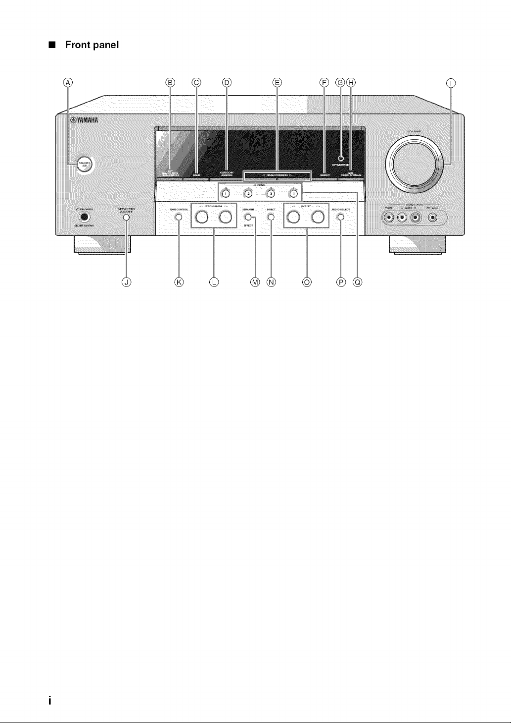
• Front panel
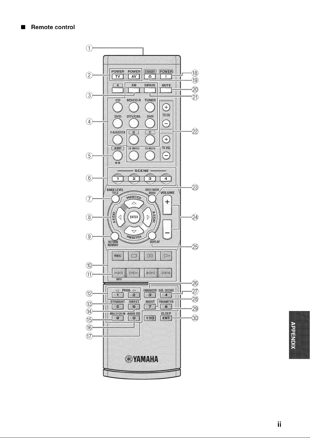
• Remote control
®
@
®
ii
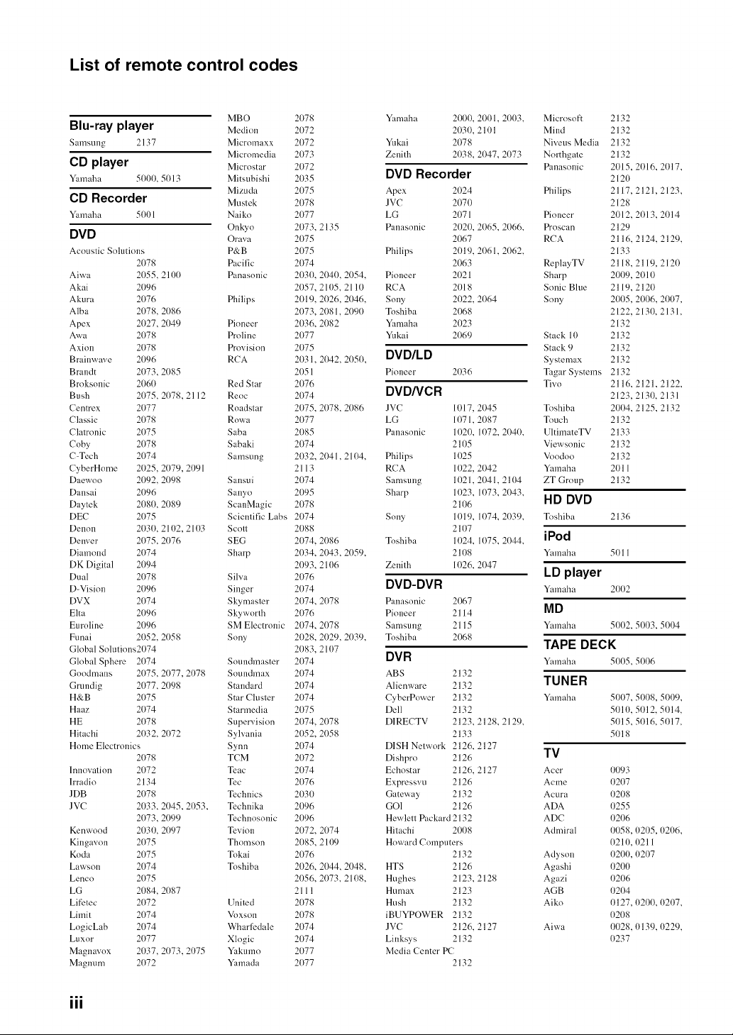
List of remote control codes
MBO
Blu-ray player Medi.....
Samsung 2137 Micromaxx
Micromedia
CD player Microstar
Yamaha 5000. 5013 Mitsubishi
Mizuda
CD Recorder Muslek
Yamaha 5001 Naiko
Onkyo
DVD Orava
Acoustic Solutions P&B
2078 Pacific
Aiwa 2055.2100 Panasonic
Akai 2096
Akura 2076 Philips
Alba 2078. 2086
Apex 2027, 2049 Pioneer
Awa 2078 Proline
Axion 2078 Provision
Brainwave 2096 RCA
Brandt 2073, 2085
Broksonic 2060 Red Star
Bush 2075. 2078, 2112 Reoc
Centrex 2077 Roadstar
Classic 2078 Rowa
Clatronic 2075 Saba
Coby 2078 Sabaki
C-Tech 2074 Samsung
CyberHome 2025, 2079, 2091
Daewoo 2092, 2098 Sansui
Dansai 2096 Sanyo
Daytek 2080, 2089 ScanMagic
DEC 2075 Scientific Labs
Denon 2030, 211)2, 2103 Scott
Denver 2075, 2076 SEG
Diamond 2074 Sharp
DK Digital 2094
Dual 2078 Silva
D-Vision 2096 Singer
DVX 2074 Skymaster
Elta 2096 Skyworth
Euroline 2096 SM Electronic
Funai 2052, 2058 Sony
Global Solutions2074
Global Sphere 2074 Soundmaster
Goodmans 2075, 2077, 2078 Soundmax
Grundig 2077, 2098 Standard
H&B 2075 Star Cluster
Haaz 2074 Starmedia
HE 2078 Supervision
Hitachi 2032, 2072 Sylvania
Home Electronics Synn
2078 TCM
Innovation 2072 Teac
lrradio 2134 Tec
JDB 2078 Technics
JVC 2033, 2045, 2053, Technika
2073, 2099 Technosonic
Kenwood 2030. 2(t97 Tevion
Kingavon 2075 Thomson
Koda 2075 Tokai
Lawson 2074 Toshiba
Lenco 2075
LG 2084, 2(t87
Lifetec 2072 United
Limit 2074 Voxson
LogicLab 2074 Wharllzdale
Luxor 2077 Xlogic
Magnavox 2037, 2073, 2075 Yakumo
Magnum 2072 Yamada
2078 Yamaha 2000. 2001.21)03,
2072 2030.211) 1
2072 Yukai 2078
2073 Zenith 2038. 2047, 2073
2072
2035 DVD Recorder
2075 Apex 2024
2078 JVC 2070
2077 LG 2071
2073, 2135 Panasonic 2020, 2065, 2066,
2075 2067
2075 Philips 2019. 2061. 2062,
2074 2063
2030, 2040, 2054. Pioneer 2021
2057, 2105.2110 RCA 2018
2019, 2026, 2046. Sony 2022. 2064
2073, 2081, 2090 Toshiba 2068
2036, 2082 Yamaha 2023
2077 Yukai 2069
2075
2031, 21142,2050, DVD/LD
2051 Pioneer 2036
2076
2074 DVD/VCR
2075, 2078, 2086 JVC 1017, 2045
2077 LG 1071,2087
2085 Panasonic 1020, 1072, 2040,
2074 2105
2032, 2041,2104, Philips 1025
2113 RCA 1022, 2042
2074 Samsung 11)21,2041,211)4
2095 Sharp 11)23, 1073, 2(t43,
2078 2106
2074 Sony 1019. 1074. 2039,
2088 2107
2074, 2086 Toshiba 1024. 1075. 2044,
2034, 2043, 2059. 2108
2093, 2106 Zenith 1026, 2047
2076
2074 DVD-DVR
2074, 2078 Panasonic 2067
2076 Pioneer 2114
2074, 2078 Samsung 2115
2028, 2029, 2039, Toshiba 2068
2083, 21 O7
2074 DVR
2074 ABS 2132
2074 Alienware 2132
2074 CyberPower 2132
2075 [)ell 2132
2074, 2078 D1RECTV 2123, 2128, 2129,
2052, 2058 2133
2074 DISH Network 2126, 2127
2072 Dishlwo 2126
2074 Echostar 2126, 2127
2076 Expresswl 2126
2030 Gateway 2132
2096 GO1 2126
2096 Hewlett Packard 2132
2072, 2074 Hitachi 2008
2085, 211)9 Howard Computers
2076 2132
2026, 2044, 2048. HTS 2126
2056, 2073. 2108. Hughes 2123. 2128
21 I 1 Humax 2123
2078 Hush 2132
2078 iBUYPOWER 2132
2074 JVC 2126. 2127
2074 Linksys 2132
2077 Media Center PC
2O77 2132
Microsoft
Mind
Niveus Media
Northgate
Panasonic
Philips
Pioneer
Proscan
RCA
ReplayTV
Sharp
Sonic Blue
Sony
Stack 10
Stack 9
Systemax
2132
2132
2132
2132
2015, 2(i)16, 2017,
2120
2117,2121,2123,
2128
2012, 2(i)13, 2014
2129
2116.2124,2129,
2133
2118, 2119. 2120
2009, 2010
2119,2120
2005, 2006, 2007.
2122, 2130. 2131.
2132
2132
2132
2132
Tagar Systems 2132
Tivo 2116.
2123,
Toshiba 2004.
Touch 2132
UltimateTV 2133
Viewsonic 2132
Voodoo 2132
Ymnaha 2011
ZT Group 2132
HD DVD
Toshiba 2136
iPod
Yamaha 5011
LD player
Ymnaha 2002
MD
Ymnaha 5002,
TAPE DECK
Ymnaha 5005,
TUNER
Ymnaha
TV
Acer
Acme
Acura
ADA
ADC
Admiral
Adyson
Agashi
Agazi
AGB
Aiko
Aiwa
2121,2122,
2130,2131
2125,2132
5003, 5004
5O06
5007, 5008, 5009,
5010, 5t) 12.5t)14.
5t) 15, 5t) 16, 5t) 17,
5t)18
0093
t)207
t)208
t)255
0206
0058, 0205, 0206,
0210, 0211
0200, 0207
0200
0206
02O4
0127, 0200, 0207,
0208
0028, 0139, 0229,
0237
III
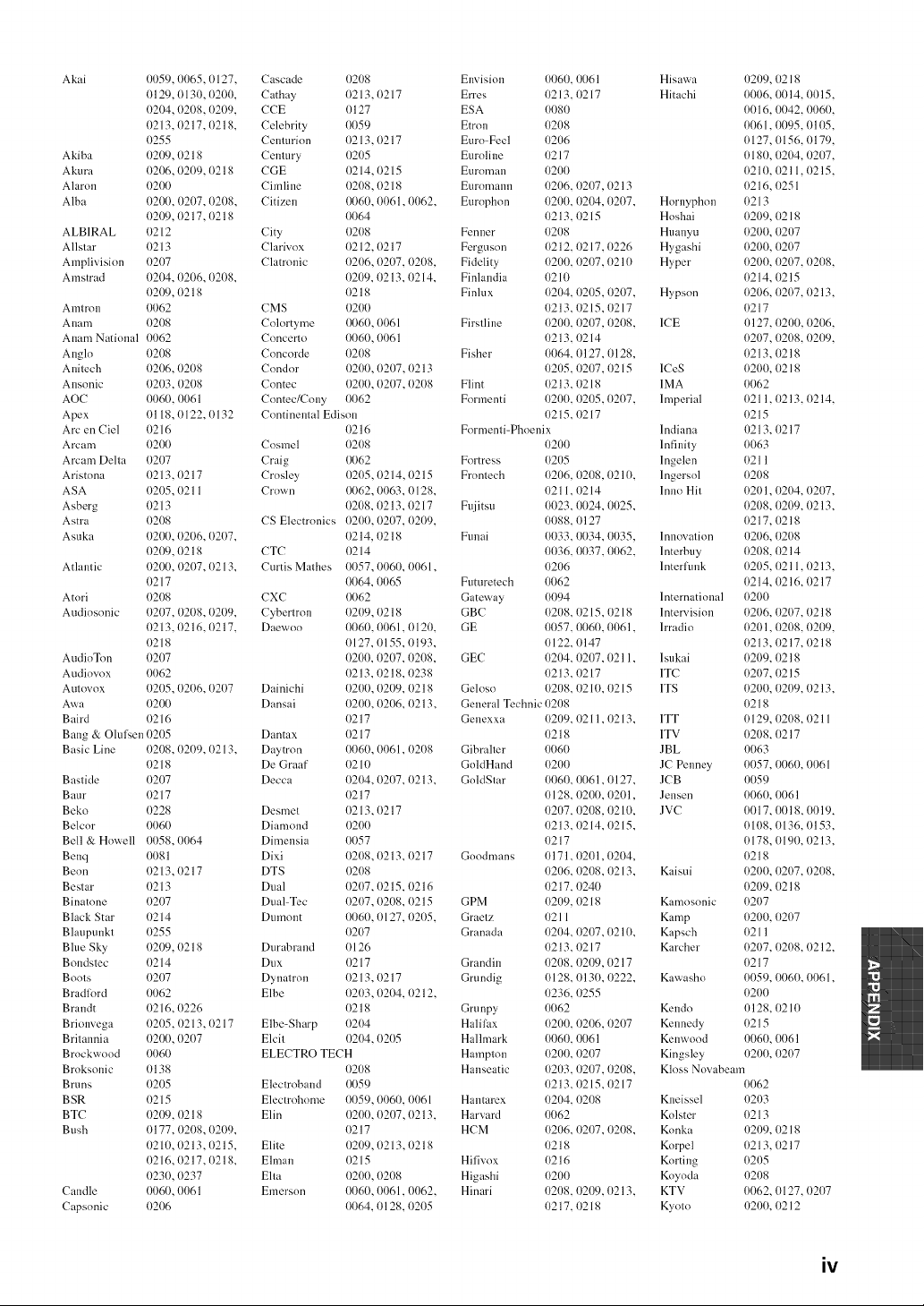
Akai 0059, 0065, 0127,
0129, 0130, 0200.
(/204, 0208, 0209,
(/213, 0217, 0218,
0255
Akiba (/209, 0218
Akura 0206, 0209, 0218
Alaron 0200
Alba 0200, 0207, 0208,
(/209, 0217, 0218
ALBIRAL {/212
Allstar {1213
Amplivisinn {/207
Amstrad t)204, 0206, 0208,
0209, 0218
Amtron 0062
A ham 0208
Anam National 0062
Angln t)208
Anitech (/206, 0208
Ansonic 0203, 0208
AOC 0060, 0061
Apex 11118, 0122, 0132
Arc en Ciel {/216
Arcam 0200
Arcam Delta (/207
Aristnna 11213, 0217
ASA {/205, (1211
Asberg 11213
Astra (/208
Asuka (/20(t, 0206, 02{t7,
(/209, 0218
Atlantic {/20(t, 0207, 0213,
{/217
Atnri {/208
Audiosonic (/207, {/208, 0209,
(/213, 0216, 0217,
11218
AudioTon 0207
Audiow) x 0062
Autnvnx (/205, (t2{t6, 02{t7
Awa (/20(t
Baird {)216
Bang & Olul%en 0205
Basic Line 0208, 02{t9, 0213,
11218
Bastide (/207
B aur 11217
Bekn (/228
Belcnr 0060
Bell & Howell (/(t58, 0064
Benq 0081
Beon 11213, 0217
Bestar 11213
Binatnne (/207
Black Star {/214
Blaupunkt 0255
Blue Sky 0209. ()218
B nndstec 11214
Boots 0207
Bradlord 0062
B randt {)216, (}226
Brionvega 0205,0213,0217
Britannia 0200, (}2{}7
Brockwnnd 0060
Broksnnic t)138
Bruns 0205
B SR 11215
BTC 0209, 11218
B ush 0177, 0208, (t209,
(/210, (t213, 0215,
(/216, (t217, 0218,
(/23(t, (t237
Candle 0060, 0061
Capsonic 0206
Cascade
Cathay
CCE
Celebrity
Centurion
Century
CGE
Cimline
Citizen
City
Clarivox
Clatronic
CMS
Colortyme
Concerto
Concorde
Condnr
Contec
Contec/Cony
(/208
0213,0217
(/127
0059
0213, 0217
{/205
(/214, 0215
0208, 0218
0060, 01161,0062,
0064
0208
0212, 0217
0206, 0207, 0208,
(}209, 11213,11214,
0218
020O
0060, 0061
0060, 0061
0208
0200, 0207, 0213
0200, 0207, 0208
0062
Continenlal Edison
0216
Cosmel
Craig
Crnsley
Crnwn
CS Electronics
CTC
Curtis Mathes
CXC
Cybertrnn
Daewno
Dainichi
Dansai
Dantax
Daytron
De Graaf
Decca
Desmet
Diamond
Dimensia
Dixi
DTS
Dual
Dual-Tec
Dumont
Dm'abrand
Dux
Dynatrnn
Elbe
Elbe-Sharp
Elcit
0208
0062
0205, 0214, 0215
0062, 0063, 0128,
0208, {1213, {1217
0200, 0207, 02{}9,
0214, {)218
(/214
0057, 0060, 0061,
0064, 0065
0062
0209, 0218
0060, 0061,0121),
0127, 0155, 0193,
0200, 0207, {/208,
0213, {/218, {/238
0200, 0209, 0218
0200, 0206, 0213,
0217
0217
0060, 0061,0208
0210
0204, 0207, 0213,
0217
0213, 0217
020O
0057
0208, 0213, 0217
0208
0207, 0215, 0216
0207, 0208, 0215
0060, 0127, 0205,
0207
0126
(/217
0213, 0217
0203, 0204, 0212,
0218
0204
0204, 0205
ELECTRO TECH
0208
Electroband
Electrohome
Elin
Elite
Elman
Elta
Emerson
0059
0059, 0060, 0061
0200, 0207, 0213,
0217
{/209, 0213, 0218
{1215
0201}, 0208
0060, 006 l, 0062,
0064, 0128, 0205
Envision 0060, 0061 Hisawa 0209, 0218
Erres {1213,{1217 Hi tachi 0006, 0014, 0015,
ESA 0080 0016. 0042, 0060,
Etron {/208 0061,0095, 0105,
Euro-Feel 0206 0127,0156,0179,
Euroline {1217 018{1, (}204, 0207,
Euronmn 0200 0210, 0211,0215,
El.lromanll {/206, {/207, 0213 0216,0251
Europhon 0200, {/204, 0207, Hornyphon 0213
{1213,{1215 Hoshai 0209, 0218
Fenner 0208 Huanyu 0200, 0207
Ferguson 0212, {/217, 0226 Hygashi 0200, 0207
Fidelity 0200, 0207, 0210 Hyper 0200, 0207, 0208,
Finlandia 0210 0214, 0215
Finlux 0204, 0205, 0207, Hypson 0206, 0207, 0213,
(/213, (/215, (/217 0217
Firstline 0200, 0207, 0208, ICE 0127, 0200, 0206,
0213,0214 0207, 0208, (/2{)9,
Fisher 0064, 0127, 0128, 0213, 0218
{/205, {/207, {1215 ICeS 0200, 0218
Flint 0213, {1218 1MA 0062
Formenti 0200, {/205, 02{}7, Imperial 0211,0213, 0214,
{1215,{1217 0215
Formenti-Phoenix Indiana {1213,0217
0200 Infinity 0063
Fortress 0205 lngelen 0211
Frontech 0206, 0208. 0210, lngersnl 0208
{1211,{/214 1nno Hit 0201,0204, 0207,
Fujitsu 0023, 0024, 0025, 0208, 0209, {)213,
{/{/88,0127 0217, 0218
Funai 0033, 0034, 0035, Innovation 0206, 0208
0036, 0037, 0062, lnterbuy 0208, 0214
0206 lnteHunk 0205, 0211,0213,
Fumretech 0062 0214, 0216, 0217
Gateway 0094 International 0200
GBC 0208, 0215,0218 lntervision 0206, 0207, 0218
GE 0057, 0060, 006 l, lrradin 020 l, 0208, 0209,
0122, 0147 0213, 0217, 0218
GEC 0204, 0207, 0211, l sukai 0209, 0218
0213,0217 1TC 0207, 0215
Gelosn 0208, 0210, {/215 ITS 0200, 0209, {/213,
General Technic 0208 0218
Genexxa 0209, 0211,0213, 1TT 0129, 0208, 0211
1)218 1TV 0208, 0217
Gibmlter 0060 ]BL 0063
GnldHand 0200 JC Penney 0057, 0060, 0061
GoldStar 0060, 0061, I)127, JCB 0059
11128,0200, 11201, Jensen 0060, 0061
{/207, {/208, {/210, ]VC 0017, 0018, 0019,
{)213, 0214, 0215, 0108, 0136, {)153,
{)217 0178, 0190, 0213,
Goodmans 0171, {)201,0204, 0218
0206, 0208, {)213, Kaisui 0200, 0207, 0208,
{1217,{/240 0209, 0218
GPM 0209, 0218 Kmnosonic 0207
Graetz {)21I Kamp 0200, 0207
Granada 0204, {/207, 0210, Kapsch 0211
11213,11217 Karcher 0207, 0208, 11212,
Grandin 0208, 0209, 0217 0217
Grundig 0128, 0130, (/222, Kawasho 0059, 0060, 0061,
(/236, (/255 0200
Grunpy 0062 Kendo 0128, 0210
Halilax 0200, 0206, 0207 Kennedy 0215
Hallmark 0060, 0061 Kenwnod 0060, 0061
Hampton 0200, {/207 Kingsley 0200, 0207
Hanseatic 0203, 0207, {/208, Kloss Novabeam
{1213,{1215, {1217 0062
Hantarex {/204, 0208 Kneissel 0203
Harvm'd 0062 Knlster 0213
HCM 0206, 0207, 0208, Knnka 0209, 0218
{1218 Korpel 0213, 0217
Hilivox 0216 Korting 0205
Higashi 0200 Knynda 0208
Hinari 0208, {/209, 0213, KTV 0062, 0127, 0207
{1217,{1218 Kyntn 0200, 0212
iv
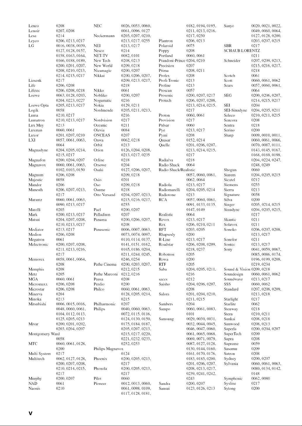
Lencn (/208 NEC 0026, 0053, 0060, (/182.
Lenoir (/207, 0208 0061,0096, 0127 11211,
Lesa (/214 Neckermann 0205, 0207. 0210. (/217.
Leyco 0206, 0213, 0217 0213, 0217, 0255 Plantron 0206,
LG 0016.0038,0039. NEI 0213,0217 Polaroid 0075
0127,0128.0157. Nesco 0214 Poppy 0208
(/158, 0163, 0164. NET-TV 0082, 0101 Portland 0060.
(/166, 0188, 0189. New Tech 0208, 0213 Prandoni-Prince (/204.
0200, 0201,0207. New World 0209, 0218 Precision 0207
(/208. 0210, 0213. Nicamagic 0200, 0207 Prima 0208.
0214,0215,0217 Nikkai 0200,0206,0207, Profex 0208
Liesenk 0217 0209, 0213, 0217, Profi-Tronic 0213
Lift-" 0206, 0208 0218 Proline 0213
Lifetec 0206, 0208, 0218 Nikko 0061 Proscan 0057
Loewe 0063, 0128, 0203, Nobliko 0200, 0207 Prosonic 0200,
(/204, 0223, 0227 Nogamatic (/216 Protech 0206,
Loewe Opta 0205, 0213, 0217 Nokia (/129, 11211 (/213,
Logik 0058 Nordmende 0205, 0211,0213, (/217
Lu ma 11210,0217 0216 Proton 0060,
Lumatron 0210,0213,0217 Nordvision (/217 Provision 0217
Lux May 11213 Oceanic 0211 Pulsar 0060
Luxman 0060, 0061 Olevia 0084 Pye 0213.
Luxor 0201,0207, 0210 ONCEAS 0207 Pymi 0208
LX1 0057, 0061,0063. Onwa 0062, 0218 Quasar 0152,
0064 Orbit 0213 Quelle {1201.
Magnadyne (/204, 0205, 0214. Orion 0126, 0204, 0208. 11213.
11215,0217 0213, 0217, 0235 11217
Magna f_m 0200, 0204, 0207 Orline 0218 Radialva 0218
Magnavox 0060, 0061,0063. Orsowe 0204 Radio Shack 0064
t)111)2,0103, 0150 Osaki t)127, 0206, 0207. Radio Shack/Realistic
Magnum 0206, 0208 0209, 0218 0057.
Majestic 0058 Osio {/201 0062.
Mandor (/206 Oso 0209, 0218 Radiola 0213,
Manesth 0206, 0207, 0213. Osume 0218 Radiomarelli 0204.
(/217 Otto Versand 0204, 0207, 0213, Radintone 0213
Marantz 0060, 0061,0063. 0215, 0216.0217. RCA 0057.
0090, 0213, 0217 0255 0091.
Marelli 0205 Pael 0200, 0207 0147.
Mark 0200, 0213, 0217 Palladium (/207 Realistic 0064
Matsui (/204, 0207, 0208. Panama 0200, 0206, 0207. Revox 0213.
11210,0213, 0217 0208 Rex 0206.
Mediator 11213,0217 Panasonic 0006, 0007, 0063. RFT (/203.
Medion 0206, 0208 0073, 0074. 0097. Rhapsody 0200
Megatron 0061 0110, 0114, 0137. R-Line (/213.
Melectronic 0200. 0207, 0208. 0141,0151.0162. Roadstar 0206.
11211,0213, 0216, 0165, 0186, 0204, 0218,
(/217 0211,0244, 0245, Robntron 0205
Memorex 0058, 0061,0064, 0246, 0254 Rowa 0200
(/208 Pathe Cinema 0200,(/203,0207, RTF 0205
Memphis (/208 0212, 0215 Saba 0204,
Metz 0205 Pathe Marconi (/212,0216 (/216
MGA 0060, (/(/61 Pausa (/208 saccs 11212
Micromaxx (/206, 0208 Perdio 0200 Saisho 0204.
Microstar 0206, 0208 Philco 0060, 0061,0063. 0208
Minerva 0204 0128, 0205. 0214. Salora 0201.
Minoka 0213 0215 0211.
Mitsubishi 0006. 0015, 0016, Philharmonic 0207 Sambers 0204
0048, 0060, 0061. Philips 0040, 0060, 0063. Sampo 0060.
(/1(/4, 0112, 0113, 0072, 0115, 0116, (/1(/1
0125,0205,0213 0124, 0130, 0150, Samsung 0029,
Mivar (/20(/, 0201,0202, 0175, 0184, 0187, 0032,
0203, 0204, 0207 0205, 0207, 0213, 0046
Montgomery Ward 0215, 0217, 0220, 0061
0058 0221,0232, 0233, 0069
MTC 0060, 0061,0128, 0252, 0253 0087
(/200 Philips Magnavox 0130
Multi System (/217 0124 0161
Multitech 0062, 0127, 0128, Phoenix 0200, 0205, 0213, 0183
0200, 0207, 0208, 0217 11201
0210, 0214, 0215, Phonola 0200, 0205, 0213, 0208
11217 0217 (/239
Murphy 0200. 0207 Pilot 0060 (/243
NAD 0061 Pioneer 0012, 0013, 0060. Sandra 0200.
Naonis 0210 0061,0098. 0109. Sansui 0123.
0117,0128, 0181,
{/194, 0195,
{/213, 0216,
{/250
{1213
0061
11210
11211
(/207, 11217
(/207, 0208,
(/214, 0215,
0061
0217
(/214
(/206, (t2(/7,
(/214, 0215,
0060, 0061,
0064
{)217
0205, 0214
0060, 0061,
0133, 0135,
0149
{)217
0210, 0211
0205
{/217
0208, 0209,
{/237
0205, 0211,
Sanyo 0020, 0021,0022,
0049, 0060, {){)64,
0127, 0128, 0200,
0203, 0207, {1215
SBR {)217
SCHAUB LORENTZ
0211
Schneider 0207, 0209, 0213,
0215, 0216. {)217.
0218
Scotch 0061
Scott 0060, 0061, (}062
Sears 0057, 0060, 0061,
0064
SEG 0200, 0206, 0207,
0214, 0215. {)217
SE1 {/204
SEl-Sinudyne {)204,0205,0211
Seleco 11210, 0211,0215
Sencora {/208
Sentra {1218
Serino 0200
Sharp 0009, 0010, 0011.
0060, 0061. {/{/66.
0070, 0087, {1111,
0143, 0145, {)167,
0168, 0169, 0198,
0204, 0224, (/247,
0248, 0249
Shogun 0060
Siarem 0204, 0205, 0215
Sicatel {1212
Siemens (/255
Sierra {)213
Signature 0058
Silva {/20{/
Singer {/205, {)214, 0215
Sinudyne 0204, 0205, 0215,
0217
Skantic {1211
Solavox {1211
Sonoko 0206, 0207, 0208,
0213.0217
Snnolor 0211
Snntec 0213. (1217
Sony 0041. (t059. 0067.
0085, 0086.0174.
0196, 0199, 0208,
0219, 0234
Sound & Vision 0209, 0218
Soundesign 0060, 0061,0062
Soundwave {)213,0217
0206, 0207, SSS 0060, 0062
Standard 0207, 0208, 0209,
{)204, {)21O, 0213, 0218
{)215 Starlight {)217
Starlite 0062
0061,0083, Stenway {)218
Stern {)210, 0211
0030, 0031, Sunkai {/208,0218
0044, 0045, Sunwood {/208,0213
0047, 0060, Superla 0200, 0204, 02{}7
0065, 0068, SuperTech 0200
0071,0079, Supra {/208
0127, 0128, Supreme 0059
{/144, 0160, Snsumu {/209
0170, 0176, Sutron {/208
{1185,(}20(}, Sydney 0200, 0207
{/206, (}207, Sylvania 0060, (}061,0063,
{)213, 0217. 0080, 0134. 0142.
{1241,0242, 0148
Symphonic 0062, 0080
0207 Sysline {)217
0126. {1213 Sytong 0200
v
Tan@
Tashiko
Tatung
TCM
Teac
Tec
Techwood
Teknika
Teleavia
Telecor
Telefi+mken
Telegazi
Teletech
Teletnn
TelevMenn
Tensai
Tesmet
Tevion
Texet
Thomson
Thorn
TMK
Tokai
Tokyo
Toshiba
Towada
Transtec
Trident
Tristar
Triumph
Uher
Ultravox
United
Universum
Univox
Vestel
Vexa
Victor
VIDEOLOG1C
Videologique
Videosat
VideoSystem
Videotechnic
Vidtech
Viewsnnic
Visiola
Visinn
Vortec
Voxsnn
Waltham
Wards
Watsoll
Watt Radio
Wega
0127, 0207, 0209,
(1211,0218
0200, 0207, 0210
0127, 0204, 0207,
13213, 0217, 0237
0206, 0208
1/127
1/207, 0208, 0214,
11215
0060, 0061
0058, 0()6(), 0061,
0062
1/216
0218
0065, 0213, 0216
0218
0208.0214, 0217
0207
0200
0208, 0209, 0213,
0218
0213
1/206.1/208
0200. 0207
0191.0192, 0207,
0213, 0216, 0226
0212, 0217
0060. 0061
11213
0200, 0207
0027, 0043, 0053,
0054, 0064, 0078,
0089, 0090, 0106,
0107, 0127. 0131.
0140, 0146, 0159,
{)197, 0225, 0231,
{)237
0211. 0215
0200
0204
0218
0204
{)211,0213
0200, 0205, 0207,
0214, 0215
0217
1/127, 0128, 0129.
11201. 0206, 0213.
1/214. 0215, 0217
11212
1/210. 11211,0213,
1/214, 0215, 0217
1/208. 11217
11213
0200
0200, 0207, 0209.
0218
0214
11213
020O
0060, 0061
0076, 0077, 0092,
0099, 0172, 0173
0200, 0207
11213
1/213, 0217
0205. 1121O, 0211,
0213
0207, 0212
0057, 0058, 0060.
0061,0063
0213.1/217, 0218
0200. 0207, 0212.
0215
0205
Weltblick 0213, 0217
Weston 0215
White Westinghouse
0200, {)207, {)217
Yamaha 0000, 0001,0002,
0003, 0004, 0005,
0060, 0061
Yamishi 0218
Yoko 0200, 0206, 0207,
0208, 0209, 11213,
0217, 0218
Yorx 0209, 0218
Zanussi 0210
Zenith 0058, 0060, 0100,
0105, 0119, 0121,
0154
TWDVD
Aiwa 0139, 2055
Apex 0132, 2049
Broksonic {)138, 21t61/
Bush 0230, 2112
JVC 0136, 2053
Panasnnic 0137, (}254, 2054,
21111
RCA 0133, 0135, 2050,
2051
Sylvania 0134, 2052
Thomson 0226, 2109
Toshiba 0131,0231,2048,
2111
TWDVD/VCR
Panasnnic 0141, 1040, 2057
Samsung 0241, 1070, 2113
Sharp 0143, 1028, 2059
Sylvania 0142, 1041. 2058
Toshiba 0140, 1029, 2056
TV/VCR
Aiwa
Bush
Daewon
GE
Gondmans
Grundig
Hitachi
JVC
Magnavnx
Orion
Panasonic
Philips
Quasar
RCA
Roadstar
Samsung
Sharp
Sony
Sylvania
Tatung
Toshiba
Zenith
0237, 1066
0237, 1066
0155, 0238. 1038.
1067
0147, 1030
0240, 1{)69
0236, 11)62
0156 11/39
1/153 1036
{)150 1033
0235 11)65
0151 11134
0151) 0232. 0233.
111t33 1062. 11}63
0152 11/35
1/149 1032
0237 11/66
0144, 0239. 11)27.
1068
0145, 1028
0234, 11/64
0148, 1031
1/237, 1066
0146. 0237, 11/29,
1066
0154, 1037
VCR
Admiral
Advenmra
Aiwa
Akai
Akiba
Akura
1008, 1013
IO05
1005, 1042, 1043,
1044, 1066
1007, 1043
IO50
11/43, 11/51/
Alba 1044, 1050 GoldHand 105{)
American High 1004 Goldstar 1000, 1003, 1042,
Amstrad 1042 1045
Anitech 1050 Gondmans 1042, 1045, 1050,
ASA 1045. 1046 11)69
Asha 1002, 1014 Gradiente 1005
Asuka 1042, 1045, 11)46, Graetz 11)43, 11)47
1050 Granada 1046, 11)47, 1049
Audio Dynamics 1000 Grandin 11/42, 11/45. 10511!
Audiovox 1003 Grundig 11/46, 11/50. 1062
Baird 11}42. 1043, 11/47 Hanseatic 1045, 11/46
Basic Line 1044. 1050 Harley Davidson1005
Baur 1046 Harrnan/Kardon 1000
Beaumark 1002, 1014 Harwnod 1006
Bell & Howell 1001 HCM 11)50
Blaupunkt 11)46, 1048 Headquarter 1001
Broksnnic 1012, 1013 Hinari 1044, 1051}
Bush 11)44, 1051}, 11}66 Hisawa 11}44
Calix 1003 Hitachi 1007, 1010, 1039,
Candle 1002, 1003 1042, 1043, 1046,
Canon 1004 1049
CCE 1006 Hughes Network Systems
CGE 11/42, 1043 11/10
Cimline 1044, 1051t Hypson 11/44, 11/51/
Citizen 1002. 1003 hnperial 11)42
Colortyme 1000 lnno Hit 1046, 11/50
Colt 1006 Innovation 1044, 11/48
Craig 1002, 1003, 1006, Instant Replay 1004
1014 1nterbuy 11145
Crown 11/51/ lnterfimk 1046. 11/47
Curtis Mathes 1000, 1002, 1004, lntervisinn 1042
1009 lrradio 1045, 11/51/
Cybernex 1002, 1014 1TT 11143,11147
Daewno 1005. 1038. 1061, 1TV 1045
1067 JC Pem]ey 1000, 1001, 1002,
Dansai 1050 1003, 1004. 1006
Dantax 1044 JCL 1004
DBX 1000 Jensen 1007
De Graaf 1046, 1049 JVC 1000, 1001, 1007,
Decca 1042, 1043, 11}46 1011, 11)17, 1036,
Demm 1010 1{)43
Dimensia 1009 Kaisui 1050
Dual 1043, 1046 Karcher 1046
Dumont 1042. 1046, 1047, Kendn 1044
1049 Kenwond 1000. 1001, 1007.
Dynatech 1005 1011, 1043
Electrohome 1003 KLH 1006
Electrophonic 1003 Kodak 1003, 1004
Elta 10511 Knrpel 1050
Emerson 1003. 1004, 1005, Leyco 1050
1012. 1013 LG 1003. 11/42. 11/45.
Etzuko 1050 1071
Ferguson 1043 Lillztec 1044, 11/48
Fidelity 11}42 Lloyd's 11}05
Finlandia 1046. 1047, 1049 Loev,_e 11/48
Finlux 1042. 1043. 11}46, Loewe Opta 11/45, 11/46
1047, 1049 Logik 1006, 1I)5t)
FIRST LINE 1044, 1045, 1049, Luxor 1047
1050 LXI 1003
Fisher 1001, 1047 M Electronic 1042
Flint 11)44 Magnasonic 11)47
Fnrmenti/Phoenix Magnavox 1004, 1018. 1033
1046 Magnin 1003, 1014
Fuji 1004 Manesth 11150
Fujitsu 11142 Marantz 1000, 1001, 1004,
Funai 1005, 11)42 11/46, 11151
Galaxy 1042 Marta 1003
Garrard 11)(15 Matsui 11/44, 11/45
GBC 10511 Matsushita 1004
GE 1002, 1004, 11/1/9, Mediator 11/46
1014, 1030 Medinn 1044, 11148
GEC 11}46 ME1 11}04
Gelosn 1050
General Technic 1044, 1048
Gn Video 1014
vi
Memorex 1001, 1002, 1003,
1004, 1005, 1008,
1(/13, 1014. 1042,
1045, 1047
Memphis 11150
Metz 1(148
MGA 1{/14
MGN Technology
1002. 1014
Micromaxx 1044, 1048
Micmstar 1(/44, 1048
Migros 1(142
Minolta 1010
Mitsubishi 1011, 1(/42, 1046
Montgomery Ward
1008
Motorola 1004, 1008
MTC 1002, 11)14
Multitech 1002, 1005, 1006,
1{/42, 1046, 1(t5(t
Murphy 11142
National 1(148
NEC 1000, 1001, 1007,
1(111, 1043, 1051
Neckermann 1{/43, 1{/46
NEI 11)46
Nesco 111511
Nikko 1003
Noblex 1002, 11)14
Nokia 11)43, 11)47
Nordmende 11)43
Oceanic 1(/42, 1(t43
Okano 1(144
Olympus 1004
Optimus 1003, 1008
Orion 11)12, 1013, 1044,
1(165
Orson 11)42
Osaki 1(/42, 1{t45, 1(t5(/
Otto Versand 1(146
Palladium 1(/43,
Panasonic 1004,
1040,
11172
PatheMarconi 1043 Samsung 1(t()2, 1(/14, 1021,
Penney 101{/, 1014 1{/27, 1{/52, 1{t68,
Pentax 1010, 1049 107(1
Perdio 1042 Sanky 1008
Philco 1004, 11151 Sansui 1(}07, 1011, 1013,
Philips 1004, 1(/25, 11t33, 1043
1046, 1056, 1(/57, Sanyo 1(t()1, 1(/(t2, 1(/14,
1059, 1062, 1(/63 1047
Philips Magnavox SBR 1046
1{t18 Schaub Lorenz 1042, 1043, 1047
Phonola 1046 Schneider 1042, 1{/44, 1{t45,
Pilot 1003 1046, 1{/5{/
Pioneer 1011, 11146 Scott 1012
Prinz 1042 Sears 1001, 1003, 1(}(}4,
Proli:x 1050 1010
Profitronic 1014 SEG 1(t50
Proline 1042 SEl-Sinudyne 1046
Proscan 1009 Seleco 1043
Prosonic 1044 Sentron 1050
Protec 1006 Sharp 1(t08, 1(/23, 1(/28,
Pye 1046, 1056 1053, 1{/73
Quarter 1001 Shintom 1006, 11147,11/5(/
Quartz 1001, 1(/47 Shivaki 1045
Quasar 1004, 11)35 Shogun 1002, 11)14
Quelle 1(/42, 1(/46, 1047 Siemens 1(/45, 1(/47
Radio Shack 1003 Signature 2(}00 1008
Radio Shack/Realistic Silva 1045
1001, 1002, 1003, Singer 1004, 1006
11}04,1005, 1{/(}8 Sinudyne 1046
Radiola 1{146 Sontec 1045
Radix 1003 Sony 1(t16, 11119,1055,
Randex 1003 106(/, 1(/64, 1(t74
RCA 1002, 1004, 1009, STS 1004. 1(/1(/
1010, 1014, 1(/15, Sunkai 1044
1022. 1032 Sunstar 1042
Realistic 1001, 1002, 1003, Suntronic 1042
1004, 1005, 1008 Sunwood 10511
Rex 1(143 Sylvania 1(}04, 1005, 1(131,
RFT 1046 1041
Roadstar 1045, 1050, 1066 Symphonic 1005
1045, 10511 Saba 1043 Taisho 1044
1020, 1034, Saisho 1044, 1050 Tmldy 1001
1048, 1054, Salora 1047 Tashiko 1003, 1(142
Tamng 1007, 1042, 1043,
1{)46, 1066
TCM 1044, 1048
Teac 1005, 1007
Technics 1004, 1048
Teknika 1003, 1004, 1005
Teleavia 1043
Telefimken 1043
Tenosal 105{i)
Tensai 1(t42, 1045, 1(t51t
Tevion 1(/44, 1048
Thomson 1043, 1058
Thorn 1043, 1047
TMK 1002, 1014
Tokai 1045. 1050
Tonsai 1(15(I
Toshiba 1013, 1024, 1029,
1043, 1(}46, 1(}66,
1()75
Totevision 1002, 1003, 1014
Towada 1(/5(/
Towika 105{i)
Uher 1045
Unitech 1002, 1014
Universum 1042, 1045, 1{t46
Vector Research 1000
Video Concepts 1000
Videon 1044, 1048
Videosonic 1002, 1014
Wards 1002, 1003, 1004,
1005, 1006, 1008,
1010, 1014
Weltblick 1045
White Westinghouse
1013
XR- 1000 1004, 1005. 1006
Yamaha 1000, 1001, 1007
Yamishi 1(/5(/
Yokan 1050
Yoko 1045, 105(1
Zenith 1013, 1026, 1037
OYAMAHA
_ JPRINTEDWITH
ISOYINK _o
© 2008 YAMAHA CORPORATION All rights reserved.
YAMAHA ELECTRONICS CORPORATION, USA 6660 ORANGETHORPE AVE., BUENA PARK, CALIF. 90620, U.S.A.
YAMAHA CANADA MUSIC LTD. 135 MILNER AVE., SCARBOROUGH, ONTARIO M1S 3R1, CANADA
YAMAHA ELECTRONIK EUROPA G.m.b.H. SIEMENSSTR. 22-34, 25462 RELLINGEN BEI HAMBURG, GERMANY
YAMAHA ELECTRONIQUE FRANCE S.A. RU E AMBROISE CROIZAT BP70 CROISSY-BEAUBOURG 77312 MARNE-LA-VALLEE CEDEX02, FRANCE
YAMAHA ELECTRONICS (UK) LTD. YAMAHA HOUSE, 200 RICKMANSWORTH ROAD WATFORD, HERTS WD18 7GQ, ENGLAND
YAMAHA SCANDINAVIA A.B. J A WETTERGRENS GATA 1, BOX 30053, 400 43 V_,STRA FROLUNDA, SWEDEN
YAMAHA MUSIC AUSTRALIA PTY, LTD. 17-33 MARKET ST., SOUTH MELBOURNE, 3205 VIC., AUSTRALIA
YAMAHA CORPORATION
Printed in China c WN25790
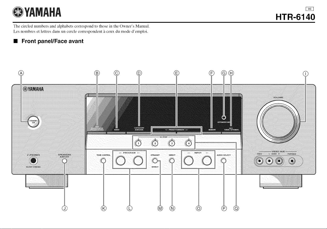
OYAMAHA
The circled numbers and alphabets correspond to those in the Owner's Manual.
Les nombres et lettres dans un cercle correspondent _ ceux du mode d'emploi.
• Front panel/Face avant
HTR-6140
© ® ® @
@ ® © @ ® @ ® @
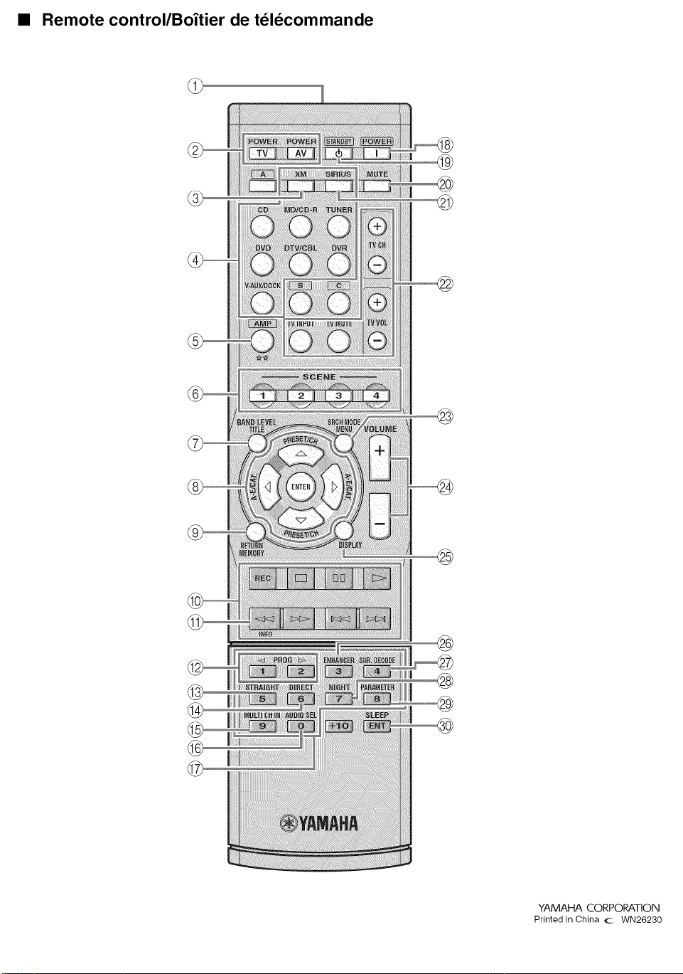
• Remote control/Bo_tier de teldcommande
@
@
®
YAMAHA CORPORATION
Printed in China c WN26230