Loading ...
Loading ...
Loading ...
Page 25
Indoor Unit
Installation
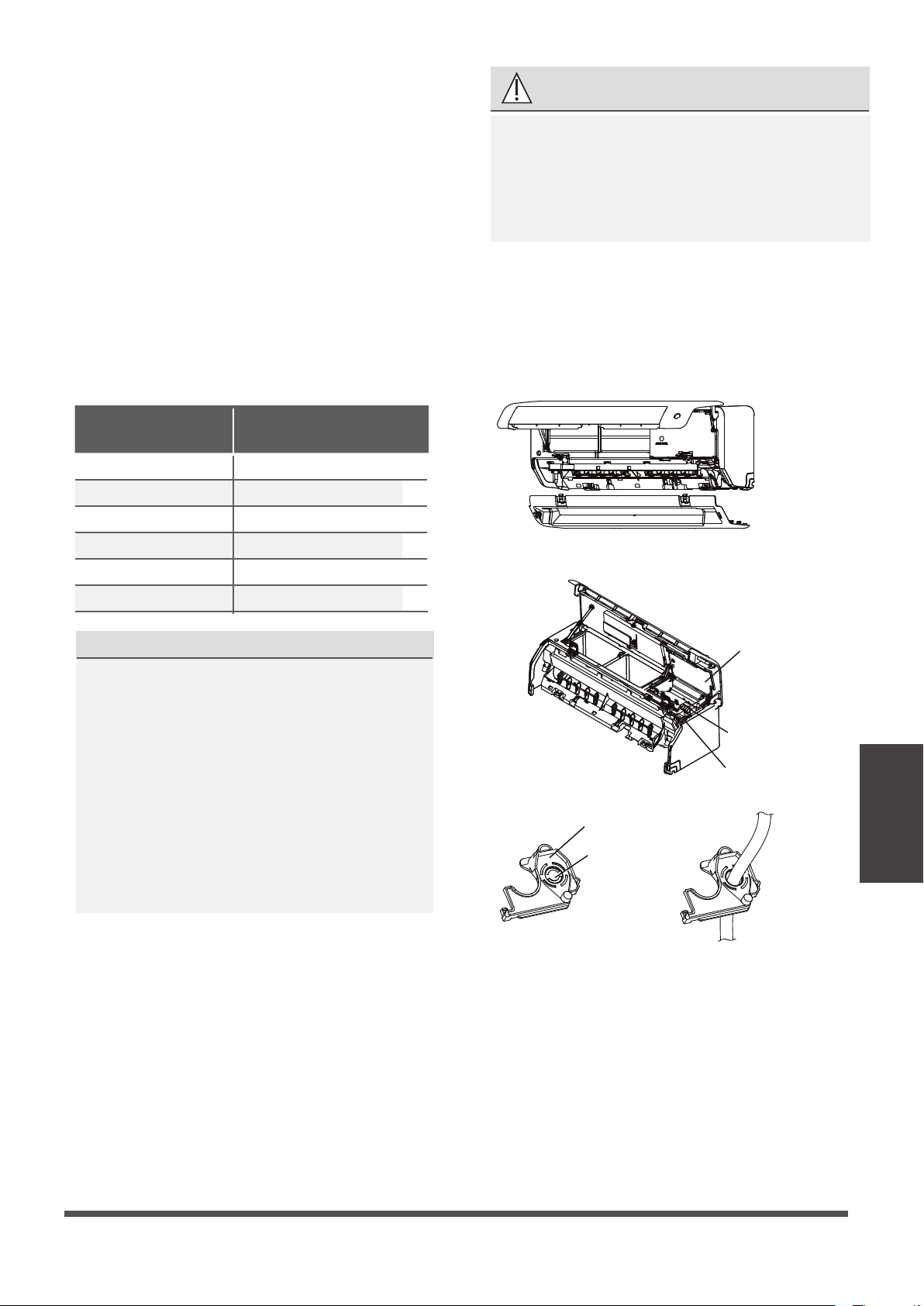
First remove the knok-out panel to create a
slot through whick the conduit tube can
install. Then make the cable through the
conduit tube and connect to the indoor unit.
First open the front panel, then remove
the lower panel.
Terminal
block
open the
Wire cover
Rat baffle(some units)
Knock-out
panel
Cable
clamp
NOTE: If the size of the cable is too big, remove
the middle small plastic knock-out panel to create
a slot through which the cable can exit. If you want
to remove the chassis or drain hose, please remove
the rat baffle first.
WARNING
1.
Open and fix the position of the panel,
then, open the covers of the two lock
blocks, unscrew the screw , then hold
both sides of the lower panel in the place
marked “PULL”, pull it upwards to release
the buckles, then take the lower panel
down (please refer to Page 22-23).
2. Open the wire box cover to connect the cable.
3.
Unscrew the cable clamp below the terminal
block and place it to the side.
4.
Facing the back of the unit, remove the plastic
panel on the bottom left-hand side.
ALL WIRING MUST BE PERFORMED
STRICTLY IN ACCORDANCE WITH THE
WIRING DIAGRAM LOCATED ON THE
BACK OF THE INDOOR UNIT S FRONT
PANEL .
’
5.
Feed the signal wire through this slot, from
the back of the unit to the front.
6.
Facing the front of the unit, connect the wire
according to the indoor unit’s wiring diagram,
connect the u-lug and firmly screw each wire
to its corresponding terminal.
In North America
Step 6: Connect signal and power cables
The signal cable enables communication between
the indoor and outdoor units. You must first choose
the right cable size before preparing it for connection.
Cable Types
•
Indoor Power Cable
(if applicable):
H05VV-F or H05V2V2-F
•
Outdoor Power Cable: H07RN-F or H05RN-F
•
Signal Cable: H07RN-F
(Not applicable for North America)
NOTE: In North America, choose the cable type
according to the local electrical codes and regulations.
Minimum Cross-Sectional Area of
Power and Signal Cables (For reference)
Rated Current of
Appliance (A)
Nominal Cross-Sectional
Area (in-mm²)
> 3 and ≤ 6
0.02in/0.75mm
> 6 and ≤ 10
0.03in/1mm
> 10 and ≤ 16
0.05in/1.5mm
> 16 and ≤ 25
0.09in/2.5mm
> 25 and ≤ 32
0.15in/4mm
> 32 and ≤ 40
0.23in/6mm
CHOOSE THE RIGHT CABLE SIZE
The size of the power supply cable, signal
cable, fuse, and switch needed is determined
by the maximum current of the unit. The
maximum current is indicated on the nameplate
located on the side panel of the unit. Refer to
this nameplate to choose the right cable, fuse,
or switch.
NOTE: In North America, please choose the
right cable size according to the Minimum
Circuit Ampacity indicated on the nameplate
of the unit.
Loading ...
Loading ...
Loading ...