©2001–2007 Sound Devices, LLC
Sound Devices, LLC
300 Wengel Drive
Reedsburg, WI 53959 USA
Voice +1 (608) 524-0625
Fax +1 (608) 524-0655
www.sounddevices.com
MP-1
Microphone Preamplifi er
User Guide and Technical Information

MP-1 Microphone Preamplifier
User Guide and Technical Documentation
page 4
General Description
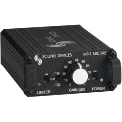
Sound Devices’ MP-1 is a portable, battery-powered microphone preamplifi er with phantom power. De-
signed for high-resolution fi eld production, this studio-quality mic pre is ideal for critical radio, televi-
sion, and fi lm production applications.
With its rugged mechanical and electrical construction, compact size and high-quality components, the
MP-1 will provide years of superb audio performance under the most punishing fi eld conditions.
Features
Audio Performance
• Maximum of 66 dB of gain, adjustable in eleven discrete steps for accurate, repeatable gain set-
tings
• Dynamic range exceeding 120 dB
• 20 Hz to 50 kHz audio bandwidth
• High immunity to RF interference due to transformers, RF fi ltering, and all-metal construction
• High current line output driver capable of driving very long cable runs
Transformer-Balanced
• Premium quality input transformer provides superior sonic quality and freedom from interfer-
ence problems
• Custom-designed output transformer provides line driving ability with freedom from interfer-
ence problems
Limiter
• Extended range peak limiter via dual opto-isolators makes unit virtually “unclippable”
Battery Powered
• Internal battery power (two AA) for convenient, low cost power
• Battery life greater than 24 hours (phantom power off)
Durable Mechanical Construction
• High strength extruded aluminum chassis with protective metal end rails to withstand punish-
ing fi eld conditions
• Easy access battery compartment for quick battery changes
Phantom Power
• Selectable 48-volt and 12-volt phantom power for condenser and dynamic microphones
High-Pass Filter
• Two selectable corner frequencies, 80 and 160 Hz, 6 dB per octave
page 5
Specifi cations
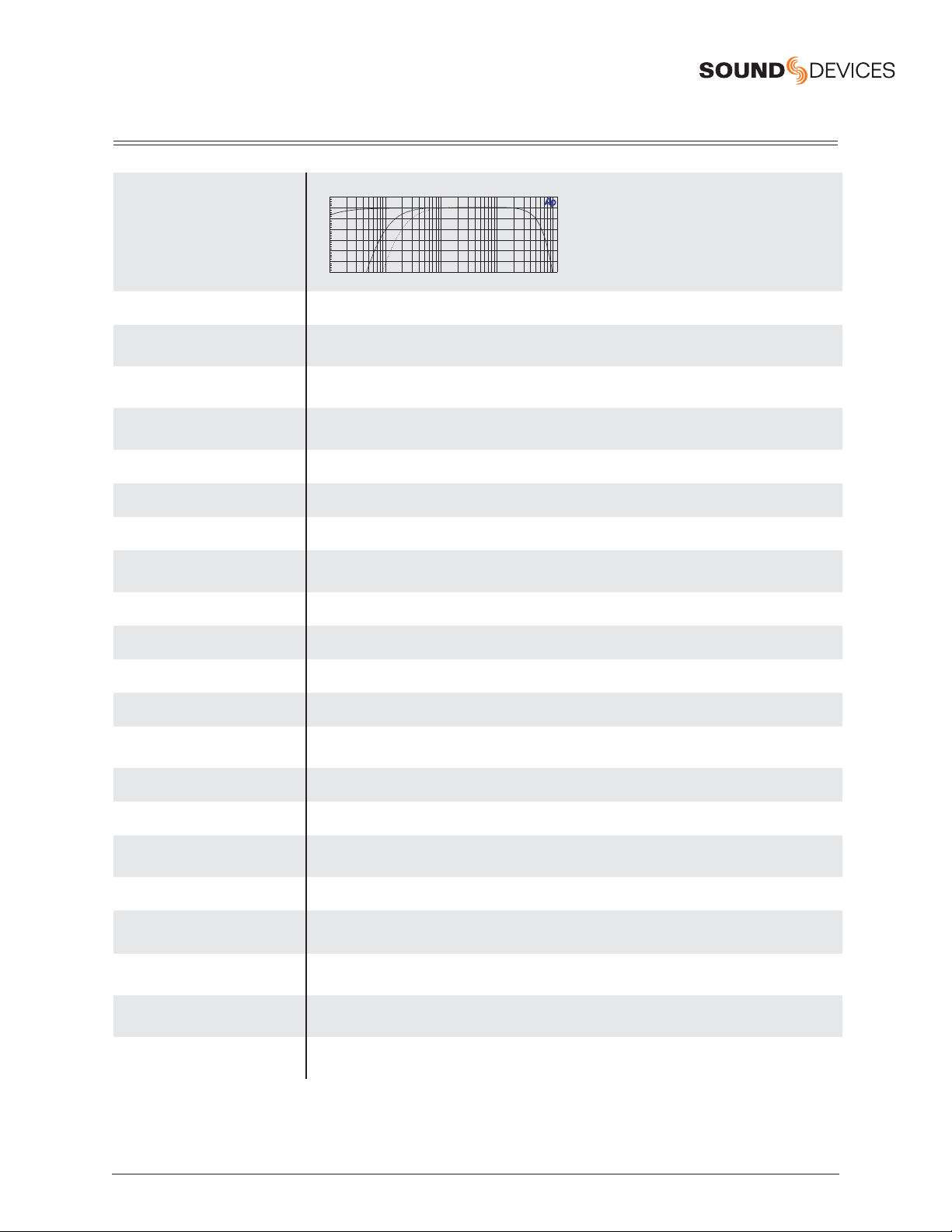
Frequency Response:
20 Hz to 22 kHz, +0.1, -0.5 dB, –1 dB at 50 kHz (relative to 1 kHz level with 150 ohm source)
-6
+1
-5
-4
-3
-2
-1
+0
d
B
u
10 100k20 50 100 200 500 1k 2k 5k 10k 20k 50k
Hz
Gain:
0 dB to 66 dB input to output, switch selectable
Gain Accuracy:
+0.6, –0.1 dB with reference to front panel gain markings
(150 ohm source, 100k ohm load impedances)
Equivalent Input Noise:
–126 dBu (–128 dBV) minimum
(150 ohm source, fl at weighting, 22–22 kHz bandwidth, gain setting 36 dB or greater
Output Clipping Level:
+22 dBu minimum with 100k ohm load
+20 dBu minimum with 600 ohm load
Input Clipping Level:
+4 dBu minimum at the 0 or +18 dB gain setting
Dynamic Range:
122 dB minimum at the +18 dB gain setting
THD + Noise:
0.05% maximum (from 50 Hz – 22 kHz @ +4 dBu output level, +46 dB gain setting)
Common Mode Rejection Ratio:
100 dB minimum at 80 Hz
60 dB minimum at 10 Hz
Input:
Transformer-balanced, 2000 ohm input impedance
Output:
Transformer-balanced, 130 ohm output impedance
Low Cut:
80 Hz or 160 Hz (switch selectable), 6 dB per octave
Phantom Power:
12-volt or 48-volt (switch selectable) per DIN 45 596 specification
Limiter:
Limits to +17 dBu output level 10:1 limiting ratio; 5 mS attack time, 100 mS release time;
Amber/Red LED indicates limiting/clipping
Internal Voltage Rails:
±15 V, regulated
Power:
2 AA batteries, 24 hours life typical with +4 dBu signal into 600 ohms, no phantom power.
Power LED:
Green indicates power and good battery. Red indicates power with low batteries. LED turns red when
approximately 4 hours of battery life remain.
Polarity:
Mic input to line output is non-inverting
Operating Temperature Range:
0° to 70° C 32° to 160° F
Dimensions:
43 mm x 94 mm x 140 mm (h x w x d)
(1.7” x 3.7” x 5.55”)
Weight: (unit only):
0.56 kg, 1.24 lbs (unit only)
0.86 kg, 1.90 lbs (packaged)
Certification:
Meets FCC Part 15 Class B
Eligible to bear CE mark (see conformance statement)
MP-1 Microphone Preamplifier
User Guide and Technical Documentation
page 6
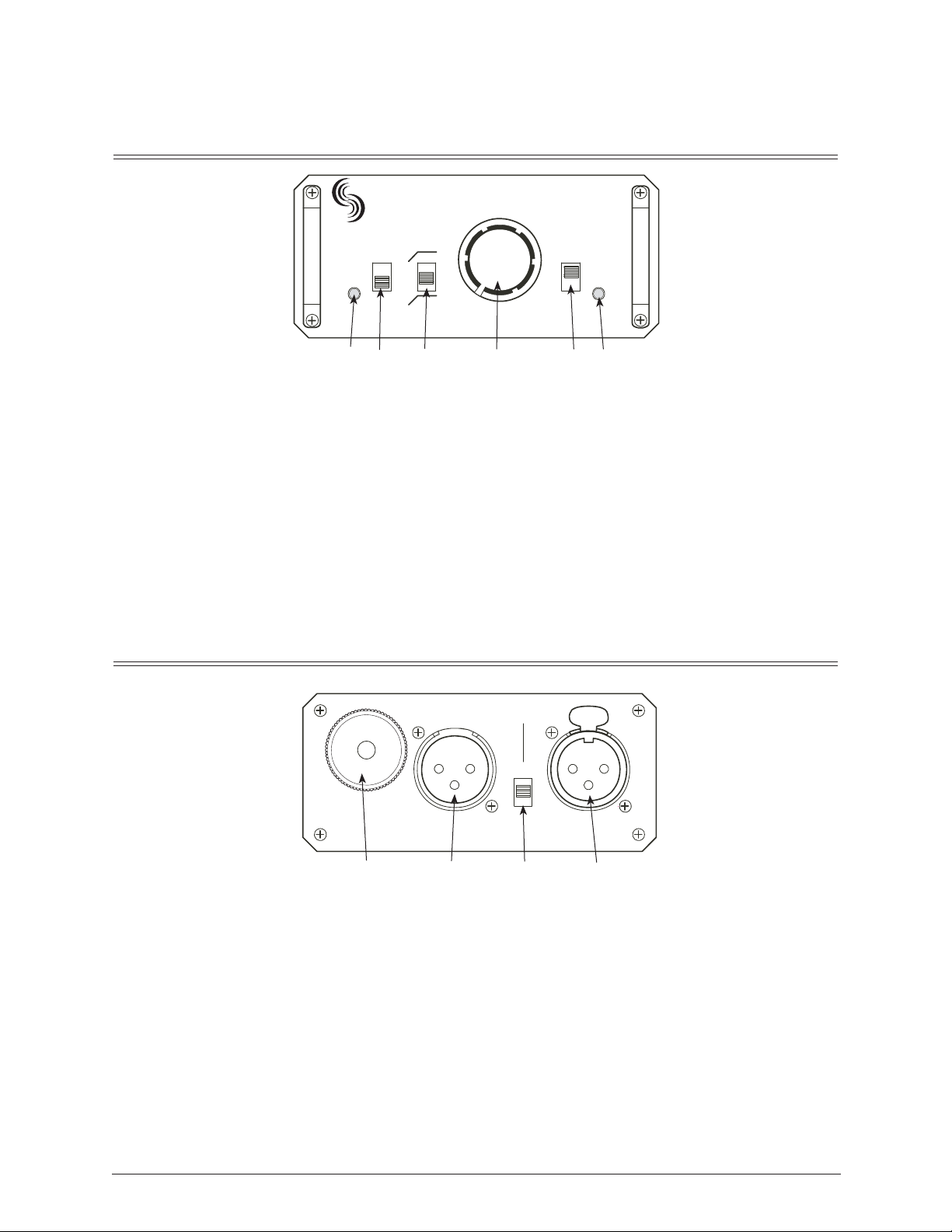
Front Panel Controls and Indicators
LIMITER POWER
160
80
MP-1 MIC PRESOUND DEVICES
FLAT
GAIN (dB)
ON ON
0
18
28
36
42
46
50
54
58
62
66
12 3 4 56
1. LIMITER/Peak LED
Bi-color LED illuminates red at 3 dB below
clipping; illuminates amber to indicate limiter
activity.
2. LIMITER Switch
Activates the peak limiter. Limits to +17 dBu
output.
3. High-Pass Filter Switch
Three-position switch selects inserts an 80 Hz
or 160 Hz corner frequency fi lter, 6 dB per
octave. Center position of switch removes the
fi lter from the signal path.
4. Rotary Gain Switch
Selects the amount of gain from input to out-
put, adjustable in 11 increments.
5. POWER Switch
Powers the unit when switch is in the up posi-
tion.
6. POWER LED
Bi-color LED illuminates green when the unit
is powered and changes to red when approxi-
mately four hours of battery life remain.
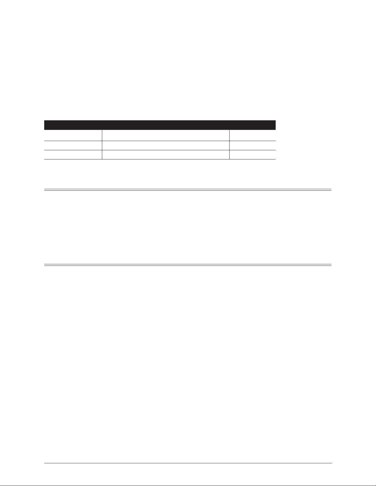
Back Panel Connectors and Controls
78910
MIC INLINE OUT
PHANTOM
48 V
12 V
OFF
BATTERIES
7. BATTERY Compartment
Requires two AA batteries for operation. Insert
positive (+) end of battery fi rst.
8. LINE OUT
Transformer balanced XLR line-level output.
+22 dBu peak output level.
9. PHANTOM Power Switch
Three-position switch selects either 48-volt or
12-volt phantom power. Center position turns
phantom power off.
10. MIC IN
Transformer-balanced XLR input accepts
microphone level signals

page 7
Operational Notes
Transformers
The isolation characteristics of transformers are superior to other balancing techniques for the adverse
and uncontrolled environments of fi eld production. Transformers provide complete galvanic isolation
from the driving source, meaning there is no direct electrical connection. Signals are “transformed”
magnetically. Both the transformers in the MP-1 use premium magnetic core material to achieve high
signal handling capability (especially at low frequencies) while keeping distortion to a minimum. Be-
cause of their inherently high common mode impedance, transformers are unrivaled by any other type
of input for common-mode noise rejection.
Both the input and output of the MP-1 can be balanced or unbalanced without any problems. When un-
balancing (either input or output) ground pin-3 to pin-1. There is no change in gain with an unbalanced
connection into or out of the MP-1.
Phantom Power
Microphones that require phantom power should use the lowest voltage acceptable to maximize battery
life. Electret-condenser microphones that can operate on phantom voltages from 11–52 volts will not
have any performance benefi t using 48-volt phantom; therefore 12-volt phantom is appropriate. Micro-
phones requiring 48-volt phantom will not operate, or may operate with lower headroom and increased
distortion, at 12 volts, therefore use 48-volt phantom. Consult your microphone documentation.
Dynamic microphones typically do not require phantom power. A properly connected balanced, dy-
namic microphone will, typically, not be affected by the presence of phantom power nor will it draw
any current. However, it is good practice to turn phantom power off if the microphone cable is suspect.
Poor or incorrectly wired microphone cable can cause audible artifacts in the microphone signal. (Phan-
tom is an excellent cable tester.)
High-Pass Filter
The two positions of the high pass fi lter (low cut) in the MP-1 are useful for removing excess low fre-
quency energy in the audio signal. The 80 Hz position is appropriate when recording general speech,
music, and ambient sound. The 160 Hz position is useful to enhance speech clarity. The high pass fi lter
is a single pole design, 6 dB per octave.
When possible, attempt to equalize at the sound source with microphone selection, use of a windscreen,
microphone placement, and onboard microphone fi ltering. A high pass fi lter on the microphone and a
high pass fi lter on the MP-1 will give an additive effect, increasing the slope of the fi lter.
Limiter
The MP-1 has a built in peak responding limiter which can be turned on or off by the switch on the front
panel. The MP-1 limiter is really two completely separate limiters activated by the one switch; the fi rst
limiter keeps the input gain stage from clipping, and the second limiter limits the output to +17 dBu.
The two limiters enable the MP-1 to limit in excess of 50 dB, meaning that it is very diffi cult to clip the
unit, no matter the gain setting. The Limiter LED on the front panel illuminates in proportion to the
amount of limiting.
MP-1 Microphone Preamplifier
User Guide and Technical Documentation
page 8
Batteries
The MP-1 is designed to operate on two AA alkaline cells for approximately 26 hours with typical sig-
nals (without phantom power). The audio performance of the MP-1 does not vary throughout the life of
the batteries.
Many factors affect battery life including—battery chemistry, ambient temperature of operation, phan-
tom voltage, microphone current draw, and output drive level. The chart below can be used as a starting
point to estimate battery life. Experimentation is recommended to determine battery life for each indi-
vidual setup. Note: Nickel-Cadmium batteries are not recommended in the MP-1 since these batteries
have lower energy per cell than other types and will result in very short service.
Battery Type Microphone Type Battery Life
Duracell AA MN 1500 Dynamic handheld 26 hrs.
Duracell AA MN 1500 Electret condenser, 12-volt phantom 18 hrs.
Duracell AA MN 1500 Studio condenser, 48-volt phantom 5 hrs.
Test conditions: 70 F, 42 dB gain with music source, 600 ohm load, +4 dBu output
FCC Statement
This device has been tested and found to comply with the limits for a class B digital device, pursuant
to part 15 of the FCC rules. These limits are designed to provide reasonable protection against harmful
interference in a residential installation. This equipment generates, uses, and can radiate radio fre-
quency energy and, if not installed and used in accordance with the instructions, may cause harmful
interference to radio communications. However, there is no guarantee that interference will not occur in
a particular installation.
Warranty
Sound Devices, LLC warrants the MM-1 Microphone Preamp with Headphone Monitoring against
defects in materials and workmanship for a period of ONE (1) year from date of original retail purchase.
This is a non-transferable warranty that extends only to the original purchaser. Sound Devices, LLC
will repair or replace the product at its discretion at no charge. Warranty claims due to severe service
conditions will be addressed on an individual basis. THE WARRANTY AND REMEDIES SET FORTH
ABOVE ARE EXCLUSIVE. SOUND DEVICES, LLC DISCLAIMS ALL OTHER WARRANTIES, EX-
PRESS OR IMPLIED, INCLUDING WARRANTIES OF MERCHANTABILITY AND FITNESS FOR A
PARTICULAR PURPOSE. SOUND DEVICES, LLC IS NOT RESPONSIBLE FOR SPECIAL, INCIDEN-
TAL, OR CONSEQUENTIAL DAMAGES ARISING FROM ANY BREACH OF WARRANTY OR UN-
DER ANY OTHER LEGAL THEORY. Because some jurisdictions do not permit the exclusion or limita-
tions set forth above, they may not apply in all cases.
For all service, including warranty repair, please contact Sound Devices for a return authorization num-
ber (RMA) before sending the unit for service. Service returns should be sent to:
Sound Devices, LLC
Service Repair (RMA # XXXX)
300 Wengel Drive
Reedsburg, WI 53959 USA
telephone: (608) 524-0625
page 9
CE Declaration of Conformity
According to ISO/IEC Guide 22
Sound Devices, LLC
300 Wengel Drive
Reedsburg, WI 53959 USA
declares that the product, MP-1 is in conformity with and passes:
EN55103-1 (1997)
EMC-product family standard for audio, video, audio-visual and
entertainment lighting control apparatus for professional use. Part 1:
Emissions
EN55103-2 (1997) EMC-product family standard for audio, video, audio-visual and
entertainment lighting control apparatus for professional use. Part 2:
Immunity
EN55022 (1995)/
CISPR 22 (1997)
Radiated and conducted emissions, Class B
EN61000-4-2 (1995)/
IEC1000-4-2 (1995)
ESD - 6kV contact, 8kV air-discharge
EN61000-4-3 (1995)/
IEC1000-4-3 (1995)
Radiated RF Immunity, 10 V/m, 80% 1 kHz amplitude modulation
EN61000-4-4 (1995)/
IEC1000-4-4 (1995)
EFT/Burst, I/O lines, +/- .25 kV to +/- 1.0 kV
EN61000-4-6 (1996)/
IEC1000-4-6 (1996)
Conducted RF Immunity, 10 V, 80% 1 kHz amplitude modulation
Tested by L. S. Compliance, Inc. Cedarburg, Wisconsin
December 16, 1999
Matthew Anderson
Director of Engineering
Sound Devices, LLC

MP-1 - Printed in U.S.A.