
MODEL
917.258591 OWNER'S MANUAL
- Assembly
oOperation
®Customer Responsibilities
-,o Service and Adjustments
®Repair Parts
CAUTION: Read and follow all safety rules and instructions before operating this equipment
FOR CONSUMER ASSISTANCE HOT LINE, CALLTHIS TOLL FREE NUMBER: 1-800-659-59t7
SAFETY RULES
Safe Operation Practices for Ride-On Mowers
IMPORTANT: THIS CUTTING MACHINE IS CAPABLE OFAMPUTATING HANDS AND FEET AND THROWING OBJECTS,.
FAILURE TO OBSERVE THE FOLLOWING SAFETY INSTRUCTIONS COULD RESULT iN SERIOUS INJURY OR DEATH+
I. GENERAL OPERATION
• Read, understand, and follow all Instructions in the manual
and on the machine before starting+
• Only allow responsible adults, who are famUiar with the
instructions, to operate the machine+
• Clear the area of objects such as rocks, toys, wire, etc.,
which could be picked up and thrown by the blade.
• Be surethe areais clearof other people before mowing+ Stop
machine if anyone enters the area_
• Never carry passengers..
• Do not mow inreverse unless absolutely necessary+ Always
look down and behind before and while backing.
° Be aware of the mower discharge direction and do not point
it at anyone+ Do not operate the mower without either the
entire grass catcher or the guard in place,
° Slow down before turning_
• Never leave a running machine unattended. Always turn off
blades, set parking brake, stop engine, and remove keys
before dismounting+
= Tum off blades when not mowing..
, Stop engine before removing grass catcher or unclogging
chute+
= Mow only in daylight or good artificial light..
• Do not operate the machine while under the influence of
alcohol or drugs..
° Watch for traffic when operating near or crossing roadways.
• Use extra care when loading or unloading the machine into
a trailer or truck,.
II. SLOPE OPERATION
Slopes are a major factor related to loss+of-control and
tipover accidents, which can result in severe injury or
death. All slopes require extra caution, tf you cannot back
up the slope or if you feet uneasy on it, do not mow it+
DO:
• Mow up and down slopes, not across+
• Remove obstacles such as rocks, tree limbs, etc+
• Watch for holes, ruts, or bumps. Uneven terrain could
overturn the machine Taft grass can hide obstacles+
° Use slow speed. Choose a low gear so that youwill not have
to stop or shift while on the slope.
• Follow the manufacturer's recommendations for wheel
weights or counterweights to improve stability
• Use extra care with grass catchers or other attachments.
These can change the stabilityof the machine.
° Keep all movement on the slopes slow and gradual Do not
make sudden changes in speed or direction+
• Avoid starting or stopping on a slope. If tires lose traction,
disengage the blades and proceed slowly straight down the
slope.
DO NOT:
° Donot turnon slopes unless necessary, andthen, turnslowly
and gradually downhill, if possible+
° Do not mow near drop-offs, ditches, or embankments+ The
mower could suddenly turn over if a wheel is over the edge
of a cliff or ditch, or if an edge caves in+
° Do not mow on wet grass. Reduced traction could cause
sliding+
° Do not try to stabilize the machine by puttingyourfoot on the
ground,
• Do not use grass catcher on steep slopes.
Iii. CHILDREN
Tragic accidents can occur if the operator is not alert to the
presence of children. Children are often attracted to the
machine and the mowing activity. Never assume that
children will remain where you last saw them+
• Keep children out of the mowfng area and under the watchful
care of another responsible adult+
• Be alert and turn machine off if children enter the area+
• Before and when backing, look behind and down for small
children.
• Never carry children They may fall off and be seriously
injured or interfere with safe machine operation+
° Never allow children to operate the machine.
• Use extra care when approaching blind corners, shrubs,
trees, or other objects that may obscure vision.+
IV. SERVICE
° Use extra care in handling gasoline andother fuels. They are
flammable and vapors are explosive+
Use only an approved container.
Never remove gas cap or add fuel with the engine
running, Allow engine to cool before refueling., Do not
smoke,.
Never refuel the machine indoors.
Never store the machine or fuel container inside where
there is an open flame, such as a water heater+
• Never run a machine inside a closed area.
° Keep nuts and bolts, especially blade attachment bolts, tight
and keep equipment in good condition+
• Never tamper with safety devices. Cheu_ their proper
operation regularly.
. Keep machine free of grass, leaves, or other debris build-up+
Clean oil or fuel spillage+ Allow machine to cool before
storing+
• Stop and inspect the equipment if you strike an object.
Repair, if necessary, before restarting+
• Never make adjustments or repairs with the engine running+
° Grass catcher components are subject to wear, damage, and
deterioration, which could expose moving parts or allow
objects to be thrown. Frequently check components and
replace with manufacturer's recommended parts, when nec+
essary+
• Mower blades are sharp and can cut+ Wrap the blade(s) or
wear gloves, and use extra caution when servicing them.
° Check brake operation frequently. Adjust and service as
required.
Lookfor this symbol topotnt outimportant
safety precautions. It means
CAUTIONII! BECOME ALERTlf! YOUR
SAFETY IS INVOLVED.
IIIJlllUllllllll
I '1 II
CAUTIONi
i
Always disconnect spark plug I
wlreand place wire where it cannot contact |
spark plug In order to prevent accidental |
starting when setting up, transporting, |
A WARNING A
The engine exhaust from this product contains
chemicals known to the State of California to
cause cancer, birth defe-c-ts, or other reproduc-
tive harm.

CONGRATULATIONS on your purchase of a Sears
tractor. It has been designed, engineered and manufac-
tured to give you the best possible dependability and
performahceo
Should you experience any problem you cannot easily
remedy, please contact your nearest Sears Service Cen-
ter/Department. We have competent, well-trained tech-
nicians and the proper tools to service or repair this trac-
tor°
Please read and retain this manual The instructions will
enable you to assemble and maintain your tractor prop-
erly. Always observe the "SAFETY RULES"°
MODEL
NUMBER 917_258591
SERIAL
NUMBER
DATE OF PURCHASE
THE MODEL AN D SERIAL NUMBERS WILL BE FOUN D
ON A PLATE UNDER THE SEAT°
YOU SHOULD RECORD BOTH SERIAL NUMBER AND
DATE OF PURCHASE AND KEEP IN A SAFE PLACE
FOR FUTURE REFERENCE.
MAINTENANCE AGREEMENT
A Sears maintenance agreement is available on this prod-
ucL Contact your nearest Sears store for details.
CUSTOMER RESPONSIBILITIES
• Read and observe the safety ruleso
° Follow a regular schedule in maintaining, caring for and
using your tractor.
° Follow the instnJctions under "Customer Responsibili-
ties" and "Storage" sections of this owner's manual
PRODUCT SPECiFiCATIONS
HORSEPOWER: 16
GASOLINE CAPACITY 3.5 GALLONS
AND TYPE: UNLEADED REGULAR
OIL TYPE (API-SF/SG/SH): SAE 10W-30 (above 32°F)
SAE 5W-30 (below 32°F)
OIL CAPACITY: W/FILTER: 4_0 PINTS
W/O FILTER: 3_5 PINTS
SPARK PLUG: CHAMPION RC12YC
(GAP: .040")
VALVE CLEARANCE: NOT ADJUSTABLE
GROUND SPEED (MPH): FORWARD: 5..5
REVERSE: 2.4
TIRE PRESSURE: FRON]:[ 14 PSI
REAR: 10 PSI
CHARGING SYSTEM: 15 AMPS @ 3600 RPM
BATTERY: AMPYHR: 30
MtNo CCA: 240
CASE SIZE: U1R
BLADE BOLT TORQUE: 30-35 FT. LBS.
WARNING: This tractor is equipped with an internal
combustion engine and should not be used on or near any
unimproved forest-covered, brush-covered or grass-cov-
ered land unless the engine's exhaust system is equipped
with a spark arrester meeting applicable local or state laws
(if any)., If a spark attester is used, it should be maintained
in effective working order by the operator,
in the state of California the above is required by law
(Section 4442 of the California Public Resources Code).
Other states may have similar laws. Federal laws apply on
federal lands_ A spark arrester for the muffler is available
through your nearest Sears Authorized Service Center
(See REPAIR PARTS section of this manual).
LIMITED "rwo YEAR WARRANTY ON CRAFTSMAN RIDING EQUIPMENT
For two (2) years from the date of purchase, if this Craftsman Riding Equipment is maintained, lubricated and tuned up according
to the instructions in the owner's manual, Sears will repair or replace, tree of charge, any parts found to be defective in material
or workmanship..
This Warranty does not cover:
° Expendable items which become worn during normal use, such as blades, spark plugs, air cleaners, belts, etco
• Tire replacement or repair caused by punctures from outside objects, such as nails, thorns, stumps, or glass_
• Repairs necessary because of operator abuse, negligence, improper storage or accident or the failure to maintain the
equipment accordingto the instructions contained in the owner's manual.
• Riding equipment used for commercial or rental purposes.
LIMITED 90 DAY WARRANTY ON BATTERY
For ninety (90) days from date of purchase, if any battery included with this riding equipment proves defective in material or
workmanship and our testing determines the battery will not hold a charge, Sears wil!replace the battery at no charge.
IN-HOME WARRANTY SERVICE ON YOUR CRAFTSMAN RIDING EQUIPMENT tS AVAILABLE AT NO-CHARGE FOR 30
DAYS FROM THE DATE OF PURCHASE° PLEASE CONTACT YOUR NEAREST SERVICE CENTER,. AFTER 30 DAYS
FROM THE DATE OF PURCHASE, WARRANTY SERVICE IS AVAILABLE BY'TAKING YOUR CRAFTSMAN RIDING EQUIP-
MENT TO YOUR NEAREST SEARS SERVICE CENTER. (IN-HOME WARRANTY SERVICE WILL STILL BE AVAILABLE
AFTER 30 DAYS FROM THE DATE OF PURCHASE BUT A STANDARD TRIP CHARGE WILL APPLY,.) THIS WARRANTY
APPLIES ONLY WHILE THIS PRODUCT tS IN THE UNITED STATES°
This Warranty gives you specific legal rights, and you may also have other rightswhich may vary from state to state,
SEARS, ROEBUCK AND COo, D/817 WA, HOFFMAN ESTATES, tL 60179
'H',"H'I'II'HI,II, II II I I Ill II I .............................
3
SAFETY RULES ............................................................ 2
PRODUCT SPECIFICATIONS ...................................... 3
CUSTOMER RESPONSIBILITIES ..................... 3, 16-19
WARRANTY .................................................................. 3
TRACTOR ACCESSORIES .......................................... 5
ASSEMBLY .............................................................. 7-10
OPERATION ........................................................... 11-16
MAINTENANCE SCHEDULE ...................................... 17
SERVICE AND ADJUSTMENTS ............................ 21-27
STORAGE .................................................................... 28
TROUBLESHOOTING ............................................ 29-30
REPAIR PARTS - TRACTOR ................................. 32-49
REPAIR PARTS - ENGINE .................................... 50-55
PARTS ORDERING/SERVICE ................ BACK COVER
INDEX
A
Accessories ........................................................5
Adjustments:
Brake .............................................. 24
Carburetor° ...................................................27
Mower
Front-To-Back ............................22
Side-To-Side .................................22
Throttle Control Cable ....................27
Air Filter, Engine ......................................20
Air Screen, Engine ........................................19
Assembly ....................................................7.10
B
Battery:
Charging ...................................................8
Cleaning ............................................18
Stadtng with Weak Battery ................26
Storage .........................................................28
Terminals ..........................................18
Belt:
Motion Ddve
Removal/Replacement ...............24
Mower Belt(s)
RemovaVReplacement ........... 23
Blade:
Sharpening .................................... 18
Replacement ................................................18
Brake Adjustment ...............................................24
C
Carburetor Adjustment .................................27
Controls, Tractor .................................... 12
Customer Responsibilities ..................17-20
Engine:
Air Filter..............................................20
AirScreen ......................................19
CoolingFins................................20
Engine Oil ......................................15,19
Fuel Filter .....................................20
Spark Plug(s) ....................................20
Traotor:
Battery.......................................... 18
Blade.............................................18
Lubrication Chart ..................... !7
Maintenance Schedule ............ i7
Tire Care ...............................8,18,25
Transaxle .......................................19
Cutting Height, Mower ............................13
E
Electrical:
interlocks and Relays ................... 26
Schematic ..............................................31
Widng Diagram ....................................32
Engine:
Air Filter ...................................................20
Air Screen .............................................19
Cooling Fins ...........................................20
Oil Change ...................................................19
Oil Level ...................................................19
Oil Type ..........................................15,19
Preparation ............................................15
Repair Parts .......................................50-55
Stading ..........................................................15
Storage ......................................................28
F
Filter:
Air Filter
......................................................
20
Fuel ...............................................................20
Fuel:
Type ...........................................................15
Storage .....................................................28
Fuse ...............................................................................26
H
Hood Removal/installation .......................26
L
Leveling Mower Deck ....................................22
Lubrication:
Chad .............................................17
Engine ......................................................19
M
Maintenance Schedule ........................t7
Mower:
Adjustment, Front-to-Back ..............22
Adjustment, Side-to-Side .................22
Blade Replacement ........................18
Blade Sharpening ...................................18
Cutting Height ..................................13
Installation ............................................29
Operation ....................................................14
Removal ..............................................2 t
Mowing Tips ............................................ 16
Muffler, ............................................................20
Spark Attester ....................................3,40
0i1:
0
Cold Weather Conditions ...........15,19
Engine ................................................19
Storage ...................................................28
Operation ..............................................12-16
Operating Mower ................................... 14
Options:
Accessories ...........................................5
Spark Arrester ...............................3,40
P
Parking Brake .....................................12-t3
Parts Bag ................................................. 6
Parts, Replacement]Repair _.................32-49
Product Specifications ...............................3
R
Repair Parts ...................................... 32-55
S
Safety Rules ...................................................... 2
Seat....................................................................8
Service and Adjustments ....................21-27
Carburetor.............................................27
Fuse ....................................................26
Hood Removal/Installation...............26
Motion Drive Belt
RemovaVReplacement ............ 24
Mower Belt(s)
Removal/Replacement ..............23
Mower Adjustment
Front4o-Back ............................22
Side-to-Side ..............................22
Mower Removal/Installation ...........21
Tire Care ..........................................8,18,25
Slope Guide Sheet ....................................59
Spark Plug(s) ..............................................20
Specifications .........................................3
Starting the Engine ...................................15
Steedng Wheel ...................................7,25
Stopping the Tractor ...............................13
Storage ......................................................28
T
ThrottleControlCable Adjustment........27
Tires..............................................8,18,25
Trouble Shooting Chad ....................29-30
Transaxle ................................................19
W
Warranty ...................................................3
Widng Diagram ............................................32
Wiring Schematic ...................................31
4

ACCESSORIES AND ATTACHMENTS
These accessories and attachments were available through most Sears retail outlets and service centers when the tractor was purchased,
Most Sears stores can order these items for you when you provide the model number of your tractor.
ENGINE
SPARK PLUG GAS CAN ENGINEOIL FUEL STABILIZER
AIR FILTER
%
,, ,, ,, ,,,,, ,,, ,i
MAINTENANCE
BLADES BELTS
PERFORMANCE
Sears offers a wide varlety ofattachments that fit your tractor Many of these are listed below with brief explanations of how they can help
you. This list was current at the time of publication;however, it may change in future years - more attachments may be added, changes
may be made in these attachments, or some may no longer be available or fit your model Contact your nearest Sears store for the
accessories and attachments that are available for your tractor.
Most of these attachments do not require additional hitches or conversion kits (those that do are indicated) and are designed for easy
attaching and detaching
AERATOR promotes deep root growth for a healthy lawn. Ta-
pered 2.5-inch steel spikes mounted on 10-inch diameter discs
puncture holes in soit at close intervals to let moisture soak in..
Steel weight tray for increased penetration..
BAGGER lets you collect grass clippings and leaves for a
healthier, heater looking lawn.. Two Permanex containers hold
30-gallon plastic bags.
BUMPER protects front end of tractor from damage.
CARTS make hauting easy. Variety of sizes available, plus
accessories such as side panel kits, toot caddy, cart cover,
protective mat and dolly..
CORING AERATOR takes small plugs out of soil to allow mois-
ture and nutrients to reach grass roots_ 36-inch swath. 24
hardened steel coring tips. 150 [b. capacity weight tray.
EASY OIL DRAIN VALVE makes oil changes easier, faster°
FRONT NOSE ROLLER canters in front of mower deck to reduce
chances of "scalping" on uneven terrain..
GANG HITCH lets you tow 2 or3 pull-behindattachments at once,
such as sweepers, dethatchers, aerators (not for use with rollers,
carts or other heavy attachments),
GAUGE WHEELS on both sides of the mower deck reduce
chances of"scalping" on uneven terrain,. For mower decks not so
equipped,
MULCH RAKE/DETHATCHER loosens soi| and flipsthatch and
matted leaves to lawn surface for easy pickup_ Twenty spring tine
teeth° Useful toprepare bare areas for seeding. Available for front
or rear mounting. HIGH PERFORMANCE REEL-ACTION
SPRING TINE DETHATCHER covers 36-inch wide path and
tosses thatch into large hopper_ Mounts behind tractor.
MULCHING CLOSE-OUT PLATE KIT, once installed, lets you
mulch, discharge or bag clippings (bagger optional) without
changing blades° For models not equipped as 3-in-! Convertible
mowers. See "MOWER" in the Repair Parts section of this
manual
RAMP TOPS AND FEET let you load and unload tractor from a
pickup truck,. Use with 2 x 8 or 2 x 10 lumber.
ROLLER for smoother lawn surface. 36-inch wide, 18-inch
diameter water-tight drum holds up to 390 lbs,.of weight,. Rounded
edges prevent harm to turf, Adjustable scraper automatically
cleans drum.
SNOW BLADE for snow removal only, 14-inch high, 48-inch wide
btade clears 42-inch path when angled left or right. Raises, lowers
with side lever. Adjustable skids; replaceable, reversible scraper
bar_ (Use with tire chains and wheel weights and/or rear drawbar
weight.)
SNOW'THROWER has 40-inch swath.. Drum-type auger handles
powdery and wet/heavy snow,. Mounts easily with simple pin
arrangement. Discharge chute adjusts from tractor seat., 6-inch
diameter spout discharges snow 10 to 50 feet. L! _controlled at
tractor seat. (Use with chains and wheel weights and/or rear
drawbar weight.)
SPRAYERS use 12-volt DC electric motor that connects to the
tractor battery or other 12-volt source, Includes booms for
automatic spraying and hand held wand for spot spraying.. Wand
has adjustable spray pattern. For appiying herbicides, insecti-
cides, fungicides and liquid fertilizers.
SPREADER/SEEDERS make seeding, fertilizing, and weed kill*
ing easy. Broadcast spreaders are also useful for granular de-
icers and sand..
SWEEPERS let you collect grass clippings and leaves.
TILLER has 5 hp engine and 36-inch swath to prepare seed beds,
cultivate and compost garden residue. Tiller has its own built-in
lift and depth control system and does NOT require a sleeve hitch.
Fits anylawn, yardorgardentractoro Simpiy hook uptothetractor
drawbar and go! Optional accessories convert unit for
dethatching, aerating, hilling.,,.without tools.
TIRE CHAINS are heavy duty; closely spaced extra-large cross
links give smooth ride, outstanding traction_
TRACTOR CAB has heavy duty vinyl fabric over tubular steel
frame, ABS plastic top; clear plastic windshield offers 360 degree
visibility. Hinged metal doors with catch, Keeps operator warm
and dry. Remove vinyl sides and windshields for use as sun
protector in summer° Optional accessories include: tinted/
tempered solid safety glass windshield with hand operated wiper;
12-volt amber caution light for mounting on cab top,
VACS for powerful collection of heavy grass clippings and leaves,.
Optional wand attachment to pick up debris in hard-to-reach
places. VACICHIPPER includes a chipper-shredder..
WEIGHT BRACKET for drawbar for snow removal applications.
Uses (1) 55 tb. weight.
WHEEL WEIGHTS for rear wheels provide needed traction for
snow removal or dozing heavy materials.
5

CONTENTS OF HARDWARE PACK
Parts Bag contents shown full size
................ ...... i ii
(1) Shoutder Bolt
5/16-18
(1) Knob
(1) Washer
17/32 x ! -3/16 x 12 Ga
tainer Springs (double loop)
(4) Retainer Springs (single loop)
In, I Iii ii illl
(2) Screws
#10 x 5/8
illulnnnl II
@
(2) Lock
Washers
#10
(2) Weld Nuts #10
__J (2) Washers 3/16 x 3/4 x 16 Gauge
(2) Hex Bolts 1/4_20 x 3/4
(2) Hex Nuts 1/4-20
_f'_'_'/(2) Washers _ (2) Lock
• '"----I /' 9/32 x 5/8 _ Washers 1/4
'_j,,J x 16 Ga,
Parts packed seParately in carton
Steering
Wheel
Manual
Seat
Mutcher
Plate
Video
Cassette
Parts Bag
..... i1,1iii,
Parts bag contents not shown full size
(2) Shoulder (2) CenteP (2) Gauge
Bolts lock Nuts Wheels
Assemblies
2) Washers 3/8x 7/8 x 14 Gauge
_'_12) Front Link Assemblies _
Steering
Wheel
Insert
(2) Keys
Slope Sheet
iiiiiiiiiiiiii iii L i iii I i iiiiiiii I L III " III
Steering
Sleeve
6
ASSEMBLY
Your new tractor has been assembled at the factory with exception of those parts left unassembled for shipping purposes_
To ensure safe and proper operation of your tractor, all parts and hardware you assemble must be tightened securely° Use
the correct tools as necessary to insure proper tightness,
TOOLS REQUIRED FOR ASSEMBLY
A socket wrench set will make assembly easier. Standard
wrench sizes are listed
(1) 3/4" wrench (2) 7/16" wrench
(1) 9/t 6" wrench Utility knife
(1) 1/2" wrench Tire pressure gauge
(1) 3/4" socket w/drive ratchet
When right and left hand is mentioned in this manual, it
means when you are in the operating position (seated
behind the steering wheel),
TO REMOVE TRACTOR FROM CARTON
UNPACK CARTON
• Remove all accessible loose parts and parts cartons
from carton (See page 6)°
• Cut, from top to bottom, along lines on all four corners
of carton, and lay panels flat.
• Remove mower and packing materials.
• Check for any additional loose parts or cartons and
remove,
BEFORE ROLLING TRACTOR OFF
SKID
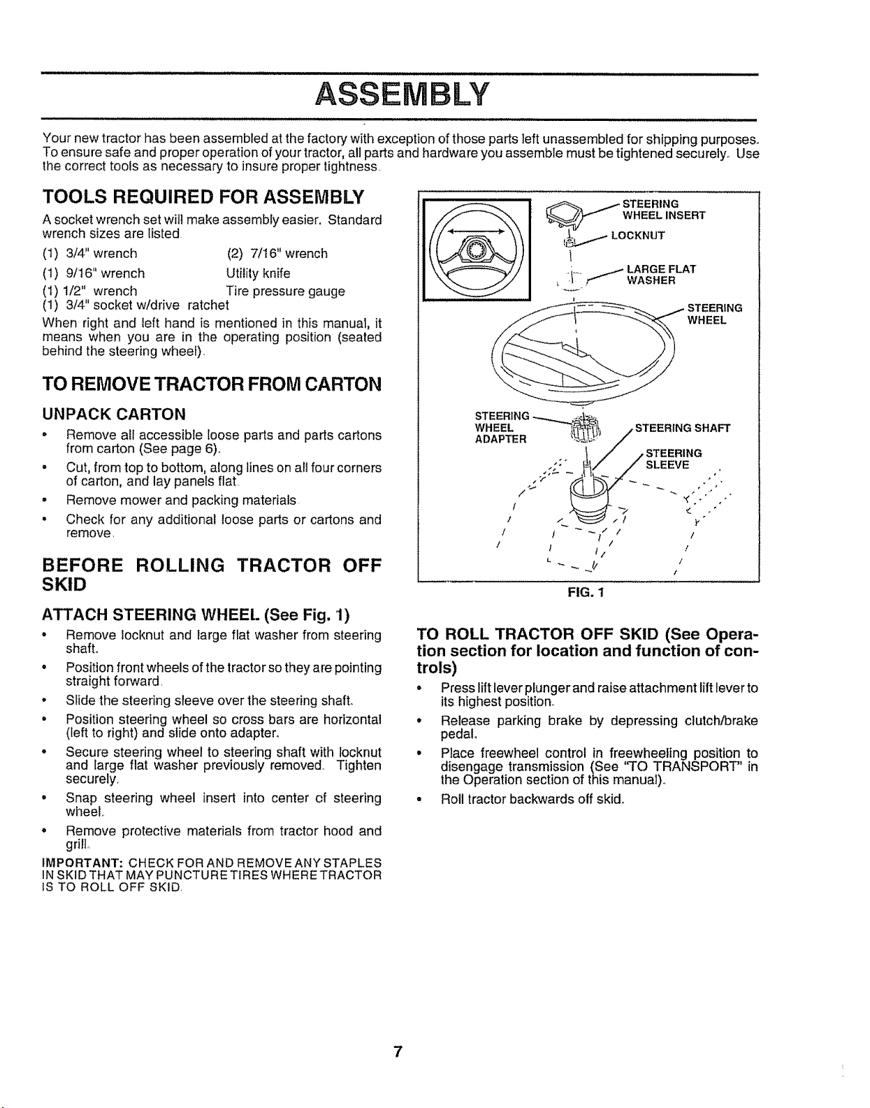
ATTACH STEERING WHEEL (See Fig. 1)
• Remove locknut and iarge flat washer from steering
shaft.
• Position front wheels of the tractor so they a re pointing
straight forward,
• Slide the steering sleeve over the steering shafL
° Position steering wheel so cross bars are horizontal
(left to right) and slide onto adapter.
o Secure steering wheel to steering shaft with locknut
and large fiat washer previously removed. Tighten
securely,
° Snap steering wheel insert into center of steering
wheel.,
• Remove protective materials from tractor hood and
grill,.
IMPORTANT: CHECK FOR AND REMOVEANY STAPLES
INSKID THAT MAY PUNCTU RE TIRES WHERE TRACTOR
IS TO ROLL OFF SKID,
/ / _" /
! /
1 I t1 ! /
FIG. 1
TO ROLL TRACTOR OFF SKID (See Opera-
tion section for location and function of con-
trols)
• Press lift lever plungerand raise attachment lift lever to
its highest position,
• Release parking brake by depressing clutch/brake
pedal.
° Place freewheel control in freewheeling position to
disengage transmission (See "TO TRANSPORT" in
the Operation section of this manual).,
• Roll tractor backwards off skid°
7
LY
HOW TO SET UP YOUR TRACTOR
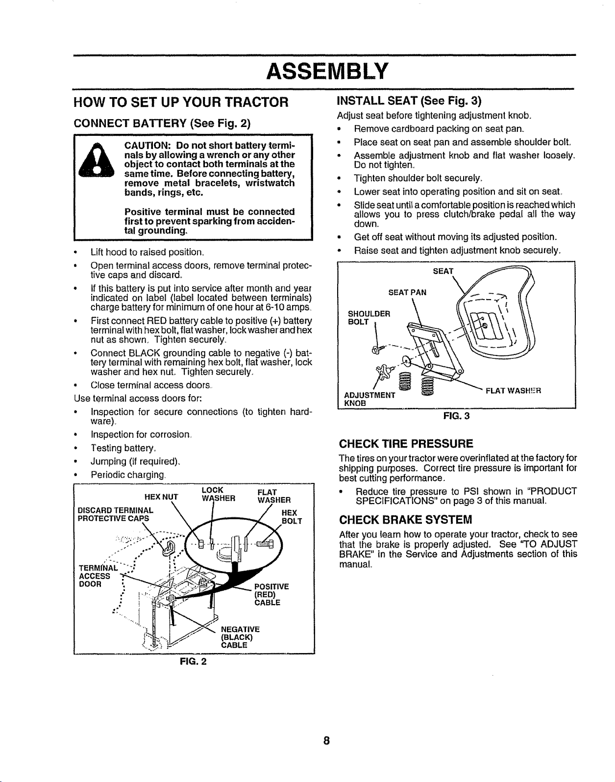
CONNECT BATTERY (See Fig. 2)
him.. i iiiilull ii ii ,,,,,,,,,,,,,,,,, 1 iiiiii nil I HI
CAUTION: Do not short batterytermi-
nats by allowing a wrench or any other
object to contact both terminals at the
same time. Before connecting battery,
remove metal bracelets, wristwatch
bands, rings, etc.
Positive terminal must be connected
first to prevent sparking from acciden-
tal grounding.
• Lift hood to raised position_
• Open terminal access doors, remove terminal protec-
tive caps and discard.,
• If this battery is put into service after month and year
indicated on label (label located between terminals)
charge battery for minimum of one hour at 6-10 amps
• First connect RED battery cable to positive (+) battery
terminal with hex bolt, flat washer, Iockwasher-and hex
nut as shown. Tighten securety_
° Connect BLACK grounding cable to negative (-) bat_
tery terminal with remaining hex bolt, flat washer, lock
washer and hex nut. Tighten securely.
• Close terminal access doors..
Use terminal access doors for:
• Inspection for secure connections (to tighten hard-
ware)_
° Inspection for corrosion,
• Testing battery.
° Jumping (if required)..
° Periodic charging.
LOCK FLAT
HEX NUT WASHER WASHER
INSTALL SEAT (See Fig. 3)
Adjust seat before tightening adjustment knob.
e
Remove cardboard packing on seat pan°
• Place seat on seat pan and assemble shoulder bolto
• Assemble adjustment knob and fiat washer loosely°
Do not tighten.,
• Tighten shoulder bolt securely,,
• Lower seat into operating position and sit on seat,
° Slide seat until a comfortable position is reache d which
allows you to press clutch/brake pedal all the way
down.
• Get off seat without moving its adjusted position.
• Raise seat and tighten adjustment knob securely.
SEAT
SEAT PAN
SHOULDER
BOLT
ADJUSTMENT
KNOB
FIG. 3
FLAT WASHER
CHECK TIRE PRESSURE
The tires on your tractor were overinflated at the factory for
shipping purposes. Correct tire pressure is important for
best cutting performance.
• Reduce tire pressure to PSi shown in "PRODUCT
SPECIFICATIONS" on page 3 of this manual
CHECK BRAKE SYSTEM
After you learn how to operate your' tractor, check to see
that the brake is properly adjusted. See "TO ADJUST
BRAKE" in the Service and Adjustments section of this
manual,,
FIG. 2
8
ASSEMBLY
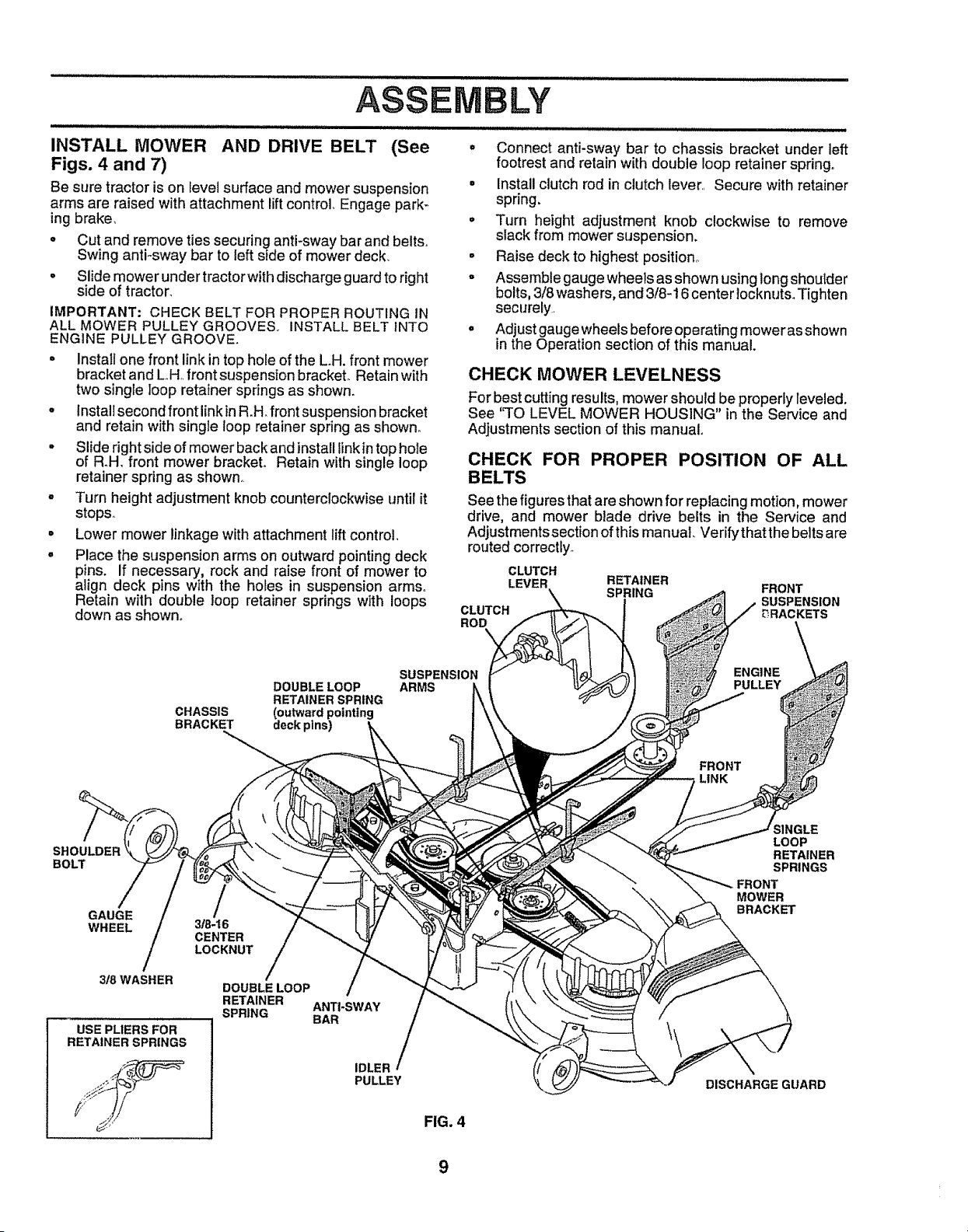
INSTALL MOWER AND DRIVE BELT (See
Figs. 4 and 7)
Be sure tractor is on level surface and mower suspension
arms are raised with attachment lift control+ Engage park-
ing brake,
o Cut and remove ties securing anti-sway bar and belts+
Swing anti+sway bar to left side of mower deck
• Slide mower under tractor with discharge guard to right
side of tractor+
IMPORTANT.* CHECK BELT FOR PROPER ROUTING IN
ALL MOWER PULLEY GROOVES, INSTALL BELT INTO
ENGINE PULLEY GROOVE.
• Install one front link in top hole of the L+H.front mower
bracket and L+H+front suspension bracket+ Retain with
two single loop retainer springs as shown.
• Install second front link inR.H. front suspension bracket
and retain with single loop retainer spring as shown.
• Slide right side of mower back and install finkin top hole
of R+H, front mower bracket. Retain with single loop
retainer spring as shown.
o Turn height adjustment knob counterclockwise until it
stops+
° Lower mower linkage with attachment lift control,
o Place the suspension arms on outward pointing deck
pins. if necessary, rock and raise front of mower to
align deck pins with the holes in suspension arms+
Retain with double loop retainer springs with loops
down as shown.
• Connect anti-sway bar to chassis bracket under left
footrest and retain with double loop retainer spring.
- Install clutch rod in clutch lever,+ Secure with retainer
spring.
° Turn height adjustment knob clockwise to remove
slack from mower suspension.
° Raise deck to highest position,
° Assemble gaugewheels as shown usinglong shoutder
bolts, 3/8 washers, and 3t8-16 center locknuts+Tighten
securely
o Adjust gauge wheels before operating mower as shown
in the Operation section of this manual.
CHECK MOWER LEVELNESS
For best cutting results, mower should be properly leveled.
See '_TOLEVEL MOWER HOUSING" in the Service and
Adjustments section of this manual
CHECK FOR PROPER POSITION OF ALL
BELTS
See the figures that are shown for replacing motion, mower
drive, and mower blade drive belts in the Service and
Adjustments section of this manual Verify'that the belts are
routed correctly,
CLUTCH
LEVER
CLUTCH
ROD
RETAINER
SPRING
FRONT
SUSPENSION
DRACKETS
DOUBLE LOOP
RETAINER SPRING
CHASSIS (outward pointing
BRACKET deck pins)
SUSPENSION
ARMS
ENGINE
PULLEY
FRONT
LINK
SHOULDER
BOLT
GAUGE
WHEEL
318 WASHER
USE PLIERS FOR
RETA|NERSPRINGS
3/8-16
CENTER
LOCKNUT
DOUBLE LOOP
RETAINER ANTI+SWAY
SPRING BAR
IDLER
PULLEY
FIG. 4
SINGLE
LOOP
RETAINER
SPRINGS
MOWER
BRACKET
DISCHARGEGUARD
JJuJ
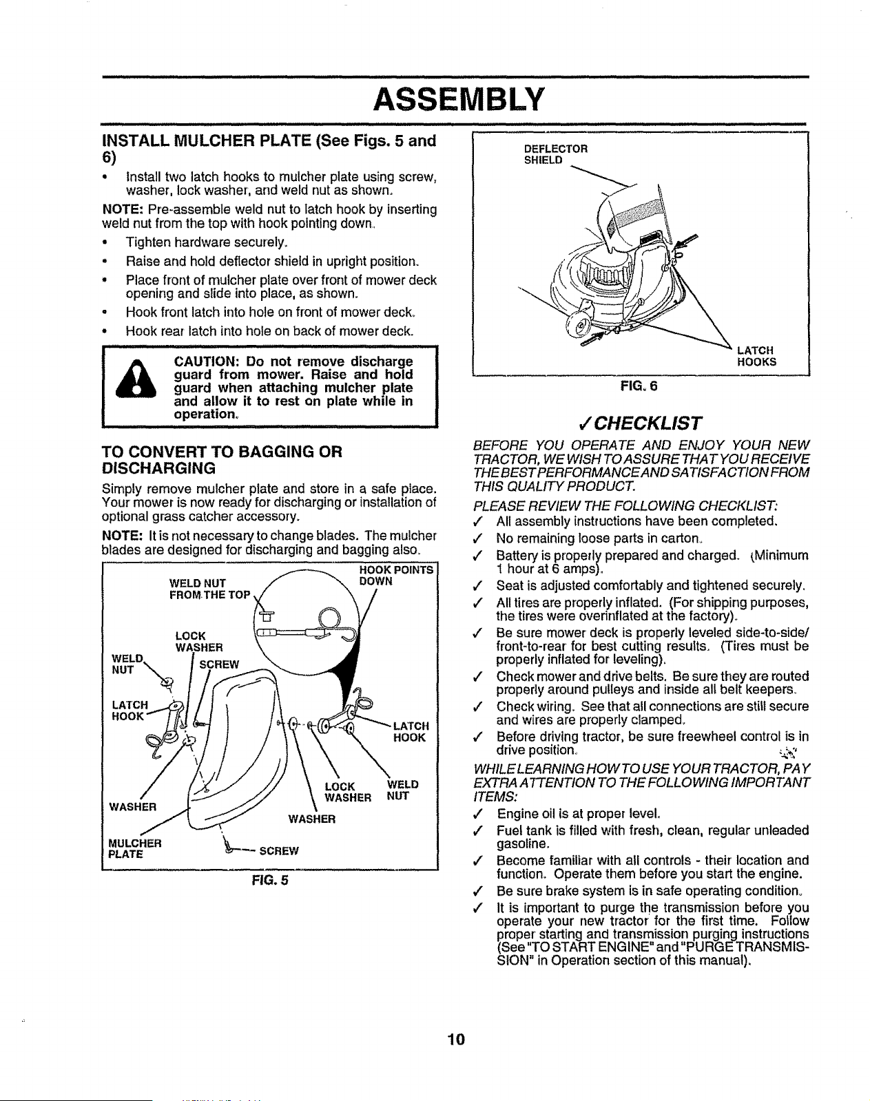
INSTALL MULCHER PLATE (See Figs. 5 and
6)
, Install two latch hooks to mulcher plate using screw,
washer, lock washer, and weld nut as shown.
NOTE; Pre-assemble weld nut to latch hook by inserting
weld nut from the top with hook pointing down
• Tighten hardware securely_
° Raise and hold deflector shield in upright position.
• Place front of nlulcher plate over front of mower deck
opening and slide into place, as shown.
• Hook front latch into hole on front of mower deck°
° Hook rear latch into hole on back of mower deck.
, ,,,,,,,,_, ,_,,, .......... ,,,, ,,, ...... IHI
CAUTION: Do not remove discharge
guard from mower. Raise and hold
guard when attaching mulcher plate
and allow it to rest on plate while in
operation,
TO CONVERT TO BAGGING OR
DISCHARGING
Simply remove mulcher plate and store in a safe place.
Your mower is now ready for discharging or installationof
optional grass catcher accessory.
NOTE- It is not necessary to change blades. The mulcher
blades are designed for discharging and bagging also.
WELD NUT
FROMTHE TOP,
HOOK POINTS
DOWN
LOCK
WASHER
WELD.
NUT \_ SCREW
LATCH
HOOK
WASHER
MULCHER
PLATE
LOCK
WASHER
WELD
NUT
FIG. 5
DEFLECTOR
SHIELD
FIG, 6
LATCH
HOOKS
,/CHECKLIST
BEFORE YOU OPERATE AND ENJOY YOUR NEW
TRACTOR, WE WISH TO ASSURE THAT YOU RECEIVE
THEBEST PERFORMANCE AND SATISFACTION FROM
THIS QUALITY PRODUCT.
PLEASE REVIEW THE FOLLOWING CHECKLIST:
v' All assembly instructions have been completed.
,/ No remaining loose parts in carton°
/ Battery is properly prepared and charged. _Minimum
1 hour at 6 amps).
,/ Seat is adjusted comfortably and tightened securely.
,/ All tires are properly inflated. (For shipping purposes,
the tires were 0verinflated at the factory)°
€" Be sure mower deck is properly leveled side-to-side/
front-to-rear for best cutting results. (Tires must be
properly inflated for leveling).
#" Check mowerand drive belts. Be sure they are routed
propedy around pulleys and inside all belt keepers.
/ Check wiring. See that all connections are still secure
and wires are properly clamped.
,/ Before driving tractor, be sure freewheel control is in
drive position°
WHILE LEARNING HOW TO USE YOUR TRACTOR, PAY
EXTRA ATTENTION TO THE FOLLOWING IMPORTANT
ITEMS:
v" Engine oil is at proper level,
,/ Fuel tank is filled with fresh, clean, regular unleaded
gasoline.
,," Become familiar with all controls - their location and
function. Operate them before you start the engine.
#" Be sure brake system is in safe operating condition°
_" It is important to purge the transmission before you
operate your' new tractor: for the first time. Follow
proper'starting and transmission purging instructions
(See "TO START ENGINE and "PURGE TRANSMIS-
SION" in Operation section of this manual),
10
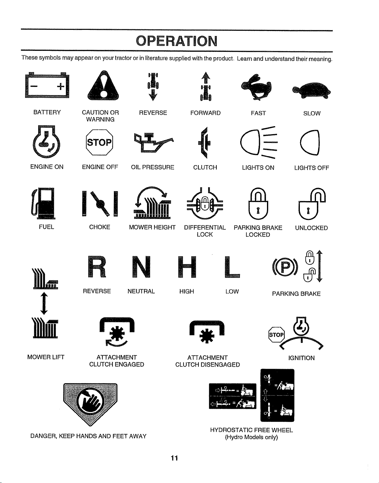
OPERATION
These symbols may appear on your tractor or in literature supplied with the product. Learn and understand their meaning_
BATTERY CAUTION OR REVERSE FORWARD FAST SLOW
WARNING
ENGINE ON ENGINE OFF OIL PRESSURE CLUTCH LIGHTS ON LIGHTS OFF
Ix! c--_@ 0
FUEL CHOKE MOWER HEIGHT DIFFERENTIAL PARKING BRAKE UNLOCKED
LOCK LOCKED
REVERSE NEUTRAL HIGH
L
LOW PARKING BRAKE
MOWER LIFT ATTACHMENT ATTACHMENT IGNITION
CLUTCH ENGAGED CLUTCH DISENGAGED
DANGER, KEEP HANDS AND FEET AWAY
HYDROSTATIC FREE WHEEL
(Hydro Models only)
11
i lll ii i llllllll illllllllllll i i i i ii HH Illlll
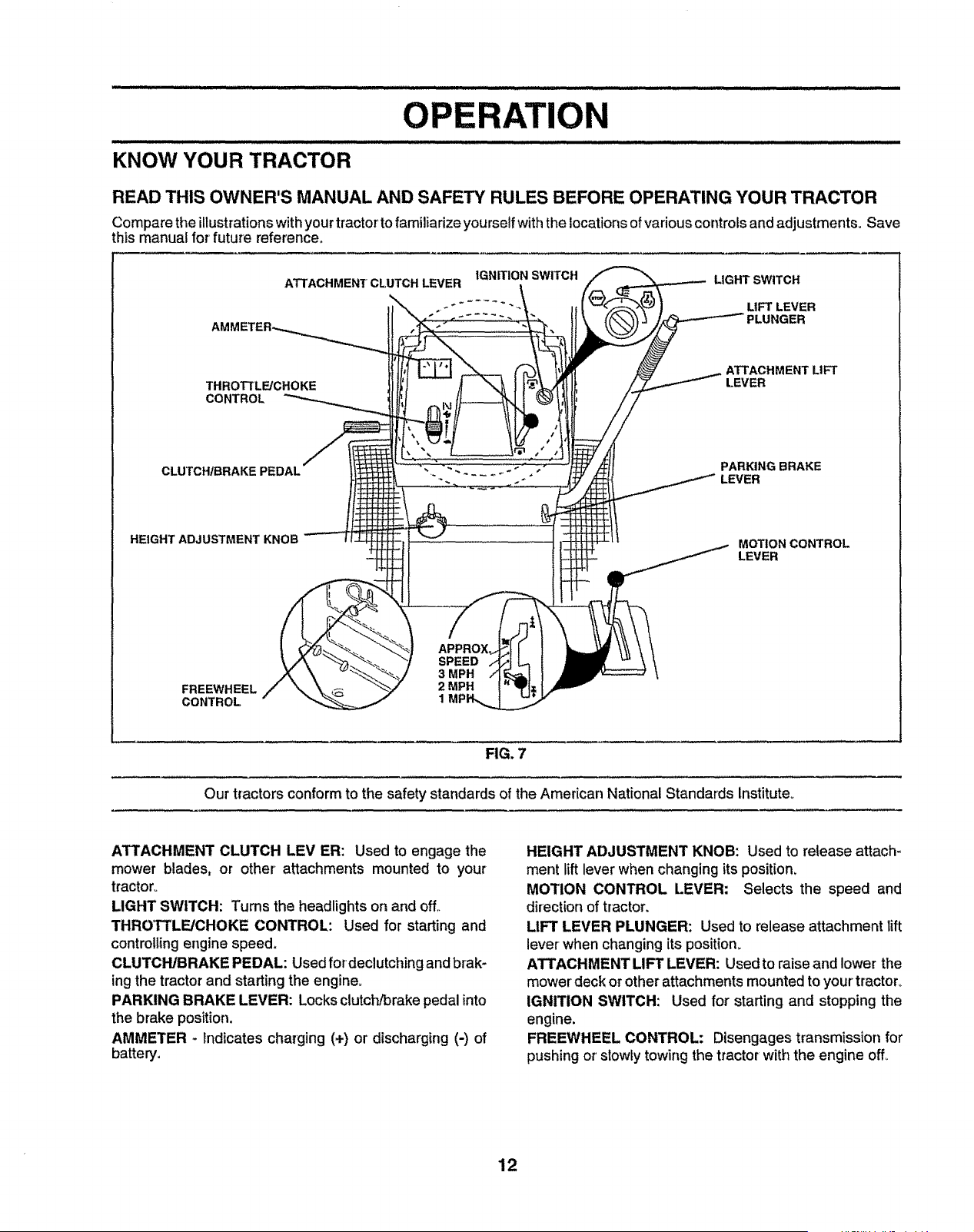
KNOW YOUR TRACTOR
OPERATION
READ THIS OWNER'S MANUAL AND SAFETY RULES BEFORE OPERATING YOUR TRACTOR
Compare the illustrationswithyourtractorto familiarize yourselfwiththe locationsof variouscontrols and adjustments_ Save
this manual for future reference_
ATTACHMENT CLUTCH LEVER
THROTTLE/CHOKE
CONTROL
IGNITION SWITCH LIGHT SWITCH
_ * ...... - LIFT LEVER
PLUNGER
CLUTCH/BRAKE
ATTACHMENT LIFT
LEVER
PARKING BRAKE
LEVER
HEIGHT ADJUSTMENT KNOB
MOTION CONTROL
LEVER
SPEED
3 MPH
FREEWHEEL 2 MPH
CONTROL 1
FIG. 7
Our tractors conform to the safety standards of the American National Standards institute°
ATTACHMENT CLUTCH LEV ER: Used to engage the
mower blades, or other attachments mounted to your
tractor°
LIGHT SWITCH: Turns the headlights on and off,.
THROTrLE/CHOKE CONTROL: Used for starting and
controlling engine speed,
CLUTCH/BRAKE PEDAL: Used for'declutching and brak-
ing the tractor and starting the engine,
PARKING BRAKE LEVER: Locks clutch/brake pedal into
the brake position.
AMMETER - Indicates charging (+) or discharging (-) of
battery,
HEIGHT ADJUSTMENT KNOB: Used to release attach-
ment lift lever when changing its position,
MOTION CONTROL LEVER: Selects the speed and
direction of tractor.
LIFT LEVER PLUNGER: Used to release attachment lift
lever when changing its position.
ATTACHMENT LIFT LEVER: Used to raise and lower the
mower deck or other attachments mounted to your tractor°
IGNITION SWITCH: Used for starting and stopping the
engine.
FREEWHEEL CONTROL: Disengages transmission for
pushing or'slowly towing the tractor with the engine off,,
12
OPERATI
,l,,,ll,l,_H ,l,Hlllllllll,l,, ,,,,,,l,,,,,,ui i,l,llll,i i i i
I _ The operation of any tractor can result in foreign objects thrown into the eyes, which can
I [L_'_r_ _E'] result in severe eye damage. Always wear safety glasses or eye shields while operating your
I _ tractor or performing any adjustments or repairs. We recommend a wide vision safety mask
I _ over the spectacles or standard safety glasses.
: :: : i,, ,,ii,ii .................... !,!,,, I L !
HOW TO USE YOUR TRACTOR
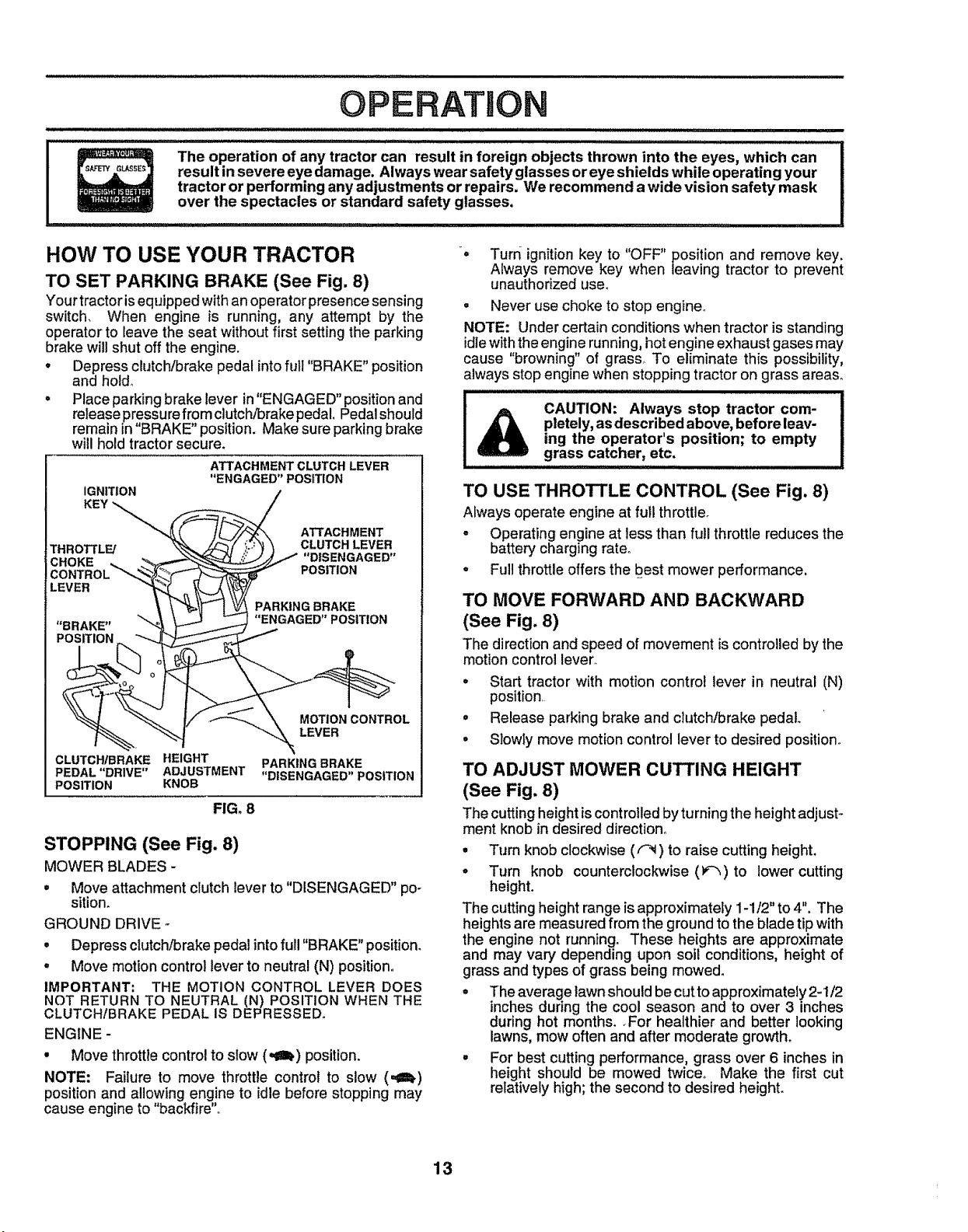
TO SET PARKING BRAKE (See Fig. 8)
Your tractor isequipped with an operator presence sensing
switch, When engine is running, any attempt by the
operator to leave the seat without first setting the parking
brake will shut off the engine.
. Depress clutch/brake pedal into futi "BRAKE" position
and hold_
° Place parking brake lever in "ENGAGED" position and
release pressure from clutch/brake pedal, Pedal should
remain in "BRAKE" position. Make sure parking brake
will hold tractor secure.
ATTACHMENT CLUTCH LEVER
"ENGAGED" POSITION
IGNITION
KEY _.
THROTTLE/
POSITION
CLUTCH/BRAKE HEIGHT
PEDAL "DRIVE" ADJUSTMENT
POSITION KNOB
FIG. 8
PARKING BRAKE
"DISENGAGED" POSITION
STOPPING (See Fig. 8)
MOWER BLADES -
• Move attachment clutch lever to "DISENGAGED" pc o
sition.
GROUND DRIVE -
• Depress clutch!brake pedal into full "BRAKE" position.
• Move motion control lever to neutral (N) position,
IMPORTANT: THE MOTION CONTROL LEVER DOES
NOT RETURN TO NEUTRAL (N) POSITION WHEN THE
CLUTCHIBRAKE PEDAL IS DEPRESSED°
ENGINE -
• Move throttlecontrol to slow (,_ub) position.
NOTE: Failure to move throttle control to slow (=,=h)
position and allowing engine to idle before stopping may
cause engine to "backfire"..
• Turn ignition key to "OFF" position and remove key.
Always remove key when leaving tractor to prevent
unauthorized use.
• Never use choke to stop engine,
NOTE: Under certain conditions when tractor is standing
idle with the engine running, hot engine exhaust gases may
cause "browning" of grass, To eliminate this possibility,
always stop engine when stopping tractor on grass areas,
CAUTION: Always stop tractor com-
pletely, as described above, before leav-
ing the operator's position; to empty
grass catcher, etc.
TO USE THROTTLE CONTROL (See Fig. 8)
Always operate engine at full throttle.
- Operating engine at less than full throttle reduces the
battery charging rate°
- Full throttle offers the best mower performance.
TO MOVE FORWARD AND BACKWARD
(See Fig. 8)
The direction and speed of movement is controlled by the
motion control lever_
° Start tractor with motion control lever in neutral (N)
position
• Release parking brake and clutch/brake pedal.
° Slowly move motion control lever to desired position°
TO ADJUST MOWER CUTTING HEIGHT
(See Fig. 8)
The cutting height is controlled by turning the height adjust-
ment knob in desired direction.
° Turn knob clockwise (f-_) to raise cutting height.
° Turn knob counterclockwise (P-_)to lower cutting
height.
The cutting height range is approximately 1-1/2" to 4". The
heights are measured from the ground to the blade tip with
the engine not running. These heights are approximate
and may vary depending upon soil conditions, height of
grass and types of grass being mowed.
° The average lawn should be cut to approximately 2-1/2
inches during the cool season and to over 3 inches
during hot months., For healthier and better looking
lawns, mow often and after moderate growth.
- For best cutting performance, grass over 6 inches in
height should be mowed twice° Make the first cut
relatively high; the second to desired height.
13
OPERATION
........:H
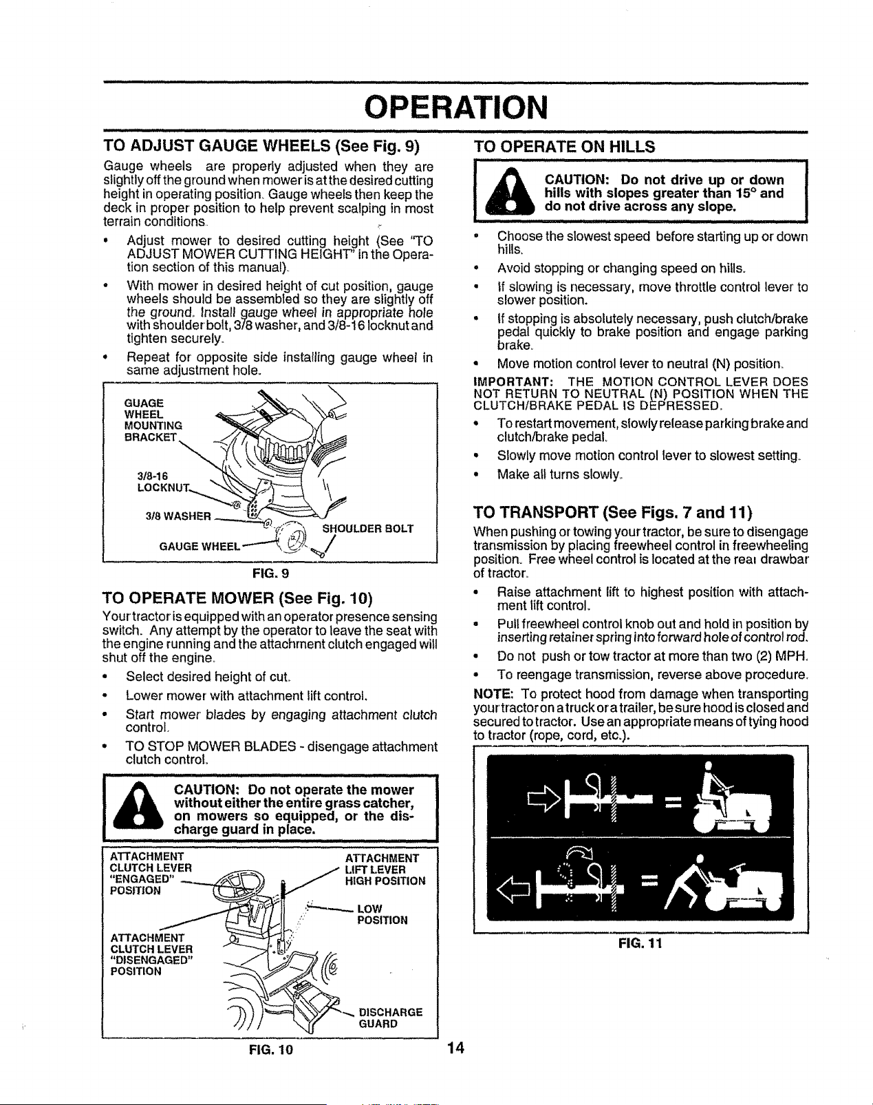
TO ADJUST GAUGE WHEELS (See Fig. 9)
Gauge wheels are properly adjusted when they are
slightly off the ground when mower is at the desired cutting
height in operating position. Gauge wheels then keep the
deck in proper position to help prevent scalping in most
terrain conditions
° Adjust mower to desired cutting height (See "TO
ADJUST MOWER CUTTING HEIGHT' inthe Opera-
tion section of this manual)
• With mower in desired height of cut position, gauge
wheels should be assembled so they are slightly off
the ground. Install gauge wheel in appropriate hole
with shoulder bolt, 3/8 washer, and 3/8-16 Iocknut and
tighten securely
• Repeat for opposite side installing gauge wheel in
same adjustment hole.
........................................................ :: ........ :::.?... :..............
TO OPERATE ON HILLS
CAUTION: Do not drive up or down
hills with slopes greater than 15° and
do not drive across any slope.
• Choose the slowest speed before starting up or down
hills,
° Avoid stopping or changing speed on hills.
• if slowing is necessary, move throttle control lever to
slower position.
• If stopping is absolutely necessary, push clutch/brake
pedal quickly to brake position and engage parking
brake.
° Move motion control lever to neutral (N) positiorL
IMPORTANT: THE MOTION CONTROL LEVER DOES
NOT RETURN TO NEUTRAL (N) POSITION WHEN THE
CLUTCH/BRAKE PEDAL IS DEPRESSED_
• To restart movement, slowly release parking brake and
clutch/brake pedal,
• Slowly move motion control lever to slowest setting°
• Make all turns slowly.
FIG. 9
TO OPERATE MOWER (See Fig. 10)
Your tractorisequipped withan operator presence sensing
switch. Any attempt by the operatorto leave the seat with
the engine runningand the attachment clutchengaged will
shut off the engine_
• Select desired height of cut.
Lower mower with attachment lift control.
t
i
Start mower blades by engaging attachment clutch
control.
TO STOP MOWER BLADES - disengage attachment
clutch control°
l i_l_ CAUTION: Do not operate the mower
without either the entire grass catcher,
on mowers so equipped, or the dis-
charg e guard in place.
ATTACHMENT ATTACHMENT
CLUTCH LEVER LIFT LEVER
"ENGAGED" HIGH POSITION
POSITION
ATTACHMENT
CLUTCH LEVER
"DISENGAGED"
POSITION
"_ DISCHARGE
GUARD
TO TRANSPORT (See Figs. 7 and 11)
When pushingortowingyour tractor,be sure to disengage
transmissionby placing freewheel controlin freewheeling
position. Free wheel controlis located at the real drawbar
of tractor.
• Raise attachment lift to highest position with attach-
ment lift control.
• Pull freewheel control knob out and hold in position by
insertingretainer spring intoforward hole of control rod.
• Do not push or tow tractor at more than two (2) MPH.
• To reengage transmission, reverse above procedure.
NOTE: To protect hood from damage when transporting
your tractor on atruck ora trailer, be sure hood is closed and
secured to tractor. Use an appropriate means of tying hood
to tractor (rope, cord, etc.).
FIG. 11
FIG. 10 14
OPEBA ON
BEFORE STARTING THE ENGINE
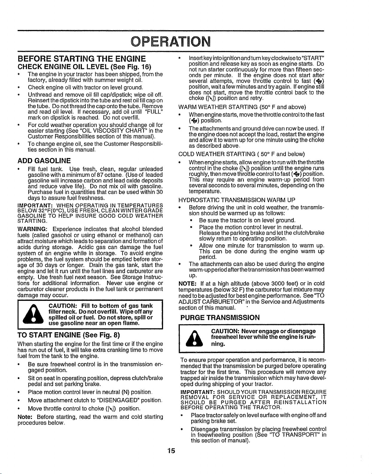
CHECK ENGINE OIL LEVEL (See Fig. 16)
• The engine in your tractor has been shipped, from the
factory_ already filled with summer weight oil
o Check engine oil with tractor on level ground.
• Unthread and remove oil fill cap/dipstick; wipe oil off..
Reinsert the dipstick intothe tube and rest oil fill cap on
the tube. Do not th read the cap onto the tube. Remove
and read oil level If necessary, add oil until "FULL"
mark on dipstick is reached. Do not overfill.
° For cold weather operation you should change oil for
easier starting (See "OIL VISCOSITY CHART' in the
Customer Responsibilities section of this manual).
° To change engine oil, see the Customer Responsibili-
ties section in this manual
ADD GASOLINE
° Fill fuel tank. Use fresh, clean, regular unleaded
gasoline with a minimum of B7octane (Use of leaded
gasoline will increase carbon and lead oxide deposits
and reduce valve life). Do not mix oil with gasoline.
Purchase fuel in quantities that can be used within 30
days to assure fuel freshness.
IMPORTANT: WHEN OPERATING IN TEMPERATURES
BELOW 32°F(0°C), USE FRESH, CLEAN WINTER GRADE
GASOLINE TO HELP INSURE GOOD COLD WEATHER
STARTING°
WARNING: Experience indicates that alcohol blended
fuels (called gasohol or using ethanol or methanol) can
attract moisture which leads to separation and formation of
acids during storage. Acidic gas can damage the fuel
system of an engine while in storage. To avoid engine
problems, the fuel system should be emptied before stor-
age of 30 days or longer. Drain the gas tank, start the
engine and let it run until the fuel lines and carburetor are
empty. Use fresh fuel next season° See Storage Instruc-
tions for additional information,. Never use engine or
carburetor cleaner products in the fueI tank or permanent
damage may occur.
_) AUTION: Fill to bottom of gas tank
filler neck. Do not overfill. Wipe off any
spilled oil or fuet. Do not store, spill or
use gasoline near an open flame.
TO START ENGINE (See Fig. 8)
When starting the engine for the first time or if the engine
has run out of fuel, it will take extra cranking time to move
fuel from the tank to the engine.
° Be sure freewheel control is in the transmission em
gaged position.
• Sit on seat in operating position, depress clutch/brake
pedal and set parking braker
° Place motion control lever in neutrat (N) position..
° Move attachment clutch to "DISENGAGED" position..
° Move throttle control to choke (N) position.
Note: Before starting, read the warm and cold starting
procedures below.,
o Insert key intoignitionand turn keyclockwise to"START'
position and release key as soon as engine starts. Do
not run starter continuously for more than fifteen sec-
onds per minute,. If the engine does not start after
several attempts, move throttle controi to fast (,ca,)
dPosition,wait a few minutes and try again.. Ifengine still
oes not start, move the throttle control back to the
choke (N) position and retry_
WARM WEATHER STARTING (50 ° F and above)
= When engine starts, move the throttlecontrol to the fast
(,_) position.
° The attachments and ground drive can now be used° If
the engine does not accept the load, restart the engine
and allow it to warm up for one minute using the choke
as described above.
COLD WEATHER STARTING ( 50 ° F and beiow)
• When engine starts, allow engine to run with the throttle
control in the choke (]\1) position until the engine runs
roughly, then move throttle control to fast (,t_) position°
This may require an engine warm-up period from
several seconds to several minutes, depending on the
temperature.
HYDROSTATIC TRANSMISSION WARM UP
° Before driving the unit in cold weather, the transmis-
sion should be warmed up as follows:
° Be sure the tractor is on level ground,,
° Place the motion control lever in neutral
Re{ease the parking brake and let the clutch/brake
slowly return to operating position.
° Allow one minute for transmission to warm up.
This can be done during the engine warm up
period.
° The attachments can also be used during the engine
warm-up period after the transmission has been warmed
up.
NOTE: if at a high altitude (above 3000 feet) or in cold
temperatures (below 32 F) the carburetor fuel mixture may
need to be adjusted for best engine performance. See 'TO
ADJUST CARBURETOR" in the Service and Adjustments
section of this manual
PURGE TRANSMISSION
t.... A CAUTION: Never engage or disengage
freewheel lever while the engine is run-
U ning.
To ensure proper operation and performance, it is recom-
mended that the transmission be purged before operating
tractor for the first time. This procedure will remove any
trapped air inside the transmission which may have devel-
oped during shipping of your tractor.
IMPORTANT: SHOULDYOUR TRANSMISSION REQUIRE
REMOVAL FOR SERVICE OR REPLACEMENT, IT
SHOULD BE PURGED AFTER REINSTALLATION
BEFORE OPERATING THE TRACTOR..
° Place tractor safely on level surface with engine off and
parking brake seL
° Disengage transmission by placing freewheel con!rol
in freewheeling position (See _TO TRANSPORT' in
this section of manual)°
'15

ATION
• Sitting inthe tractor seat, start engine° After the engine
is running, move throttle control to slow (,im_)position_
With motion control lever in neutral (N) position, slowly
disengage clutch/brake pedal.
• Move motion control lever to full forward positionand
hold for five (5) seconds. Move lever to full reverse
position and hold for five (5) seconds. Repeat this
procedure three (3) times.
NOTE: During this procedure there will be no movement of
drive wheels. The air is being removed from hydraulic drive
system.
° Move motion control leverto neutral (N)position. Shut-
off engine and set parking brake.
• Engage transmission by placing freewheel control in
driving position (See 'q'O TRANSPORT" in this section
of manual)°
• Sittingin thetractor seat, startengine. Afterthe engine
is running, move throttle control to half (1/2) speed.
With motion control lever in neutral (N) position, slowly
disengage clutch/brake pedal°
° Slowly move motion control lever forward, after the
tractor moves approximately five (5) feet, slowly move
motion control lever to reverse position° After the
tractor moves approximately five (5) feet return the
motion control lever to the neutral (N) position. Repeat
this procedure with the motion control lever three (3)
times.
• Your tractor is now purged and now ready for normal
operation.
MOWING TIPS
o Tire chains cannot be used when the mower housing
is attached to tractor°
° Mower' should be properly leveled for best mow!ng
performance. See'q'O LEVEL MOWER HOUSING in
the Service and Adjustments section of this manual.
= The left hand side of mower' should be used for trim-
ming.
• Drive so that clippings are discharged onto the area
that has been cut. Have the cut area to the ri_.htof the
machine. This will result in a more even distnbution of
clippings and more uniform cutting.
• When mowing large areas, start by turning to the right
so that clippings will discharge away from shrubs,
fences, driveways, etc_ After one or two rounds, mow
in the opposite direction making left hand turns until
finished (See Fig_ 12).
° tf grass is extremely tall, it should be mowed twice to
reduce load and possible fire hazard from dried clip-
pings, Make first cut relatively high; the second to the
desired height.
° Do not mow grass when it is wet. Wet grass will ptug
mower and leave undesirable clumps. Allow grass to
dry before mowing.
• Always operate engine at full throttle when mowing to
assure better mowing performance and proper dis-
charge of material. Regulate ground speed by select-
ing a low enough gear to give the mower cutting
performance as welt as the quality of cut desired.
• When operating attachments, select a groundspeed
that will suit the terrain and give best perform,=nceof
the attachment being used.
FIG. 12
MULCHING MOWING TIPS
IMPORTANT: FOR BEST PERFORMANCE, KEEP
MOWER HOUSING FREE OF BUILT-UP GRASS AND
TRASH. CLEAN AFTER EACH USE,.
° The special mulching blade will recut the grass clip-
pings many times and reduce them in size so that as
they fall onto the lawn they will disperse into the grass
and not be noticed. Also, the mulched grass will biode-
grade quickly to provide nutrients ferthe lawno Always
mulch with your highest engine (blade) speed as this
will provide the best recutting action of the blades_
° Avoid cutting your lawn when itis wet. Wet grass tends
to form clumps and interferes with the mulching action°
The best time to mow your' lawn is the early afternoon,
At this time the grass has dried and the newly cut area
will not be exposed to the direct sun°
° For best results, adjust the mower cutting height so that
the mower cuts off only the top one-third of the grass
blades (See Fig. 13). For' extremely heavy mulching,
reduce your' width of cut on each pass and mow slowly.
* Certain types of grass and grass conditions may re-
quire that an area be mulched a second time to com-
pletely hide the clippings° When doing a second cut,
mow across or perpendicular to the first cut path.
, Change your cutting pattern from week to week. Mow
north to south one week then change to east to west the
next week_ This will he_pprevent matting and graining
of the lawno
MAX 1/3
FIG. 13
16

MAINTENANCE SCHEDULE ' j"___.i_ _.,_e'_j_ '"
,,YOUooM
........................
Check Brake Operation _/' @i'
............. B .... ,,,, ,
Check Tire Pressure ............[##'
Check for Loose Fasteners if
R,,. Mowo,Siad,e .........V',....................
C Lubrication Chart _
T CheckBati'o' ;'Leve,,Rie,c, ';;' ......
0 Clean Battery and Te!m!na!s .... _ _ .....
a Check Transaxte Cooling _ ..... ,.......
Adjust Blade BeEt(s) Tension _i' s
Adjust Motion Drive Belt(s) Tension ........... _5
Check Engine Oil Leve, !................r, _ _.._
Change Engine Oil 1_1,2_ _#'
. ........... : : ................
E _,_€_leanAir Filter .................... ..... _#'2 ..............................
N Clean Air Screen _=
G Inspect Muffler/spark A;r'ester _' ......
I Replace Oil Filter (If equipped) _,2
N ciean Engine Cooling Fins , _;z: ' .......
Replace Spark Plug {if
Repl.'C'e'A'_';F,terPaperCartridge ......................_ .......
Replace FueI Filter .......... _1'
I - Change more o{ten when operating under a heavy {cador in high ambient temperatures
2 _Service more often when operating In dirty or dusty conditions.
3 - If equipped with oil filler, change o_Ievery 50 hours
4 - Replace biadee more often when mowing in sandy soil
5 - if equipped with adjustable system.
6 - Not required if equipped with mafntenance-h'ee battery
7 - Tighten front axle pivot bolt 1o 35 ft.-tbs m_{mum
Do not overtighlen
GENERAL RECOMMENDATIONS
The warranty on this tractor does not cover items that have
been subjected to operator abuse or negligence. To
receive full value from the warranty, operator must maintain
tractor as instructed in this manual_
Some adjustments will need to be made periodically to
properly maintain your tractor,
All adjustments in the Service and Adjustments section of
this manual should be checked at least once each season.
• Once a year you should replace the spark plug, clean
or replace air filter, and check blades and belts for
wear.. A new spark plug and clean air filter assure
proper air-fuel mixture and help your engine run better
and last Gonger.
BEFORE EACH USE
• Check engine oil level.
• Check brake operation_
• Check tire pressure,,
° Check for loose fasteners.
®
LUBRICATION CHART
SPINDLE ZERK ®
® ®
BEARING ZERK _ BEARING ZERK
®
CLUTCH PIVOT
(_)SAE 30 MOTOR OIL
®GENERAL PURPOSE GREASE
(_) REFER TO CUSTOMER RESPONSIBILITIES "ENGINE" SECTION
IMPORTANT: DO NOT OtL OR GREASE THE PIVOT POINTS,
WHICH HAVE SPECIAL NYLON BEARINGS VISCOUS LUBRI-
CANTS WILL ATTRACT DUST AND DIRT THAT WILL SHORTEN
THE LIFE OF THE SELF-LUBRICATING BEARINGS. IF YOU
FEEL THEY MUST BE LUBRICATED, USE ONLY A DRY, POW-
17 DERED GRAPHITE TYPE LUBRICANT SPARINGLY,

CUSTOMER R ILITIES
TRACTOR
Always obsewe safety ruleswhen performingany mainte-
nance_
BRAKE OPERATION
If tractor requires more than six (6) feet stopping distance
at high speed in highest gear, then brake must be adjusted_
(See "TO ADJUST BRAKE" in the Service and Adjust-
ments section of this manual).
TIRES
• Maintain proper air pressure in all tires (See "PROD-
UCT SPECIFICATIONS" on page 3 of this manual).
= Keep tires free of gasoline, oil, or insect control chemi-
cals which can harm rubber.
• Avoid stumps, stones, deep ruts, sharp objects and
other hazards that may cause tire damage.
NOTE: To seal tire punctures and prevent flat tires due to
slow leaks, tire sealant may be purchased from your local
parts dealer° Tire sealant also prevents tire dry rot and
corrosion.
BLADE CARE
For best results mower blades must be kept sharp_ Re-
place bent or damaged blades°
BLADE REMOVAL (See Fig. 14)
° Raise mower to highest position to allow access to
blades
• Remove hex bolt, lockwasher and flat washer securing
bIade_
• Install new or resharpened blade with trailing edge up
towards deck as shown°
° Reassemble hex bolt, lock washer and flat washer in
exact order as shown.
° Tighten bolt securely (30-35 Ft. Lbsotorque).
IMPORTANT: BLADE BOLT IS GRADE 8 HEATTREATED_
NOTE: We do notrecommend sharpening blade- but ifyou
do, be sure the blade is balanced_
BLADE
FLAT WISH ER__
__ MANDREL
ASSEMBLY
TRAILING
EDGE UP
_LT (GRADE 8)*
LOCKWASHER_,.,.._
*A GRADE 8 HEAT TREATED BOLT CAN 8E
IDENTIFIED BY SIX LINES ON THE BOLT HEAD,
TO SHARPEN BLADE (See Fig. 15)
Care should be taken to keep the blade balanced, An
unbalancedblade willcause excessive vibrationand even-
tual damage to mower and engine.
° The blade can be sharpened with a file or on a gdnding
wheel. Do not attempt to sharpen while on the mower.
• To check blade balance, you will need a 5/8" diameter
steel bolt, pin,ora cone balancer. (When using a cone
balancer, follow the instructions supplied with bat-
ancer).
° Slide blade on to an unthreaded portionofthe steel bolt
or pin and hold the bolt or pin parallel with the ground.
If btade is balanced, it should remain in a horizontal
position. If either end of the blade moves downward,
sharpen the heavy end until the blade is balanced.
NOTE: Do notuse a nail for balancing blade. The lobesof
the center hole may appear to be centered, but are not.
518"BOLT
OR PiN
FIG. 15
BATTERY
Your tractor has a battery charging system which is suffi-
cient for normal use. However, periodic charging of the
battery with an automotive charger witl extend its life.
• Keep battery and terminals clean.
° Keep battery bolts tight.
• Keep small vent holes open.
• Recharge at 6-10 amperes for 1 hour.
TO CLEAN BATTERY AND TERMINALS
Corrosion and dirt on the battery and terminals can cause
the battery to "leak" power.
° Remove terminal guard.
= Disconnect BLACK battery cable first then RED bat-
tery cable and remove battery from tractor.
° Rinse the battery with plain water and dry.
° Clean terminals and battery cable ends with wire brush
until bright.
• Coat terminals with grease or petroleum jelfy.
° Reinstall battery (See "CONNECT BATTERY" in the
Assembly section of this manual).
FIG, 14
18
CUSTOMER PONSI
TRANSAXLE COOLING
The fan and cooling fins of transmission should be kept
clean to assure proper cooling°
Do not attempt to clean fan or transmission while engine is
running or while the transmission is hot°
- Inspect cooling fan to be sure fan blades are intact and
clean,,
• Inspect cooling fins for dirt, grass clippings and other
materials,, To prevent damage to seals, do not use
compressed air or high pressure sprayer to clean
cooling fins.
TRANSAXLE PUMP FLUID
The transaxle was sealed at the factory and fluid mainte-
nance is not required forthe life of the transaxle, Should the
transaxle ever leak or require servicing, contact your near-
est authorized service center/department.
V-BELTS
Check V-belts for deterioration and wear after 100 hours of
operation and replace if necessary, The belts are not
adjustable. Replace belts if they begin to slip from wear.
ENGINE
LUBRICATION
Only use high quality detergent oil rated with API service
classificationSF, SG or SH Select the oil's SAE viscosity
grade according to your expected operating temperature°
SAE VISCOSITY GRADES
_'F ...........-20" 0 _ .......30 _ 32 ° 40* 60_ 80 ° 100 °
_'C -30" .2'0° .t0 _ 0° I0' 20 _'...............30' 40 °
TEMPERATURE RANGE ANTtCiPATEO BEFORE NEXT OIL CHANGE
FIG. 16
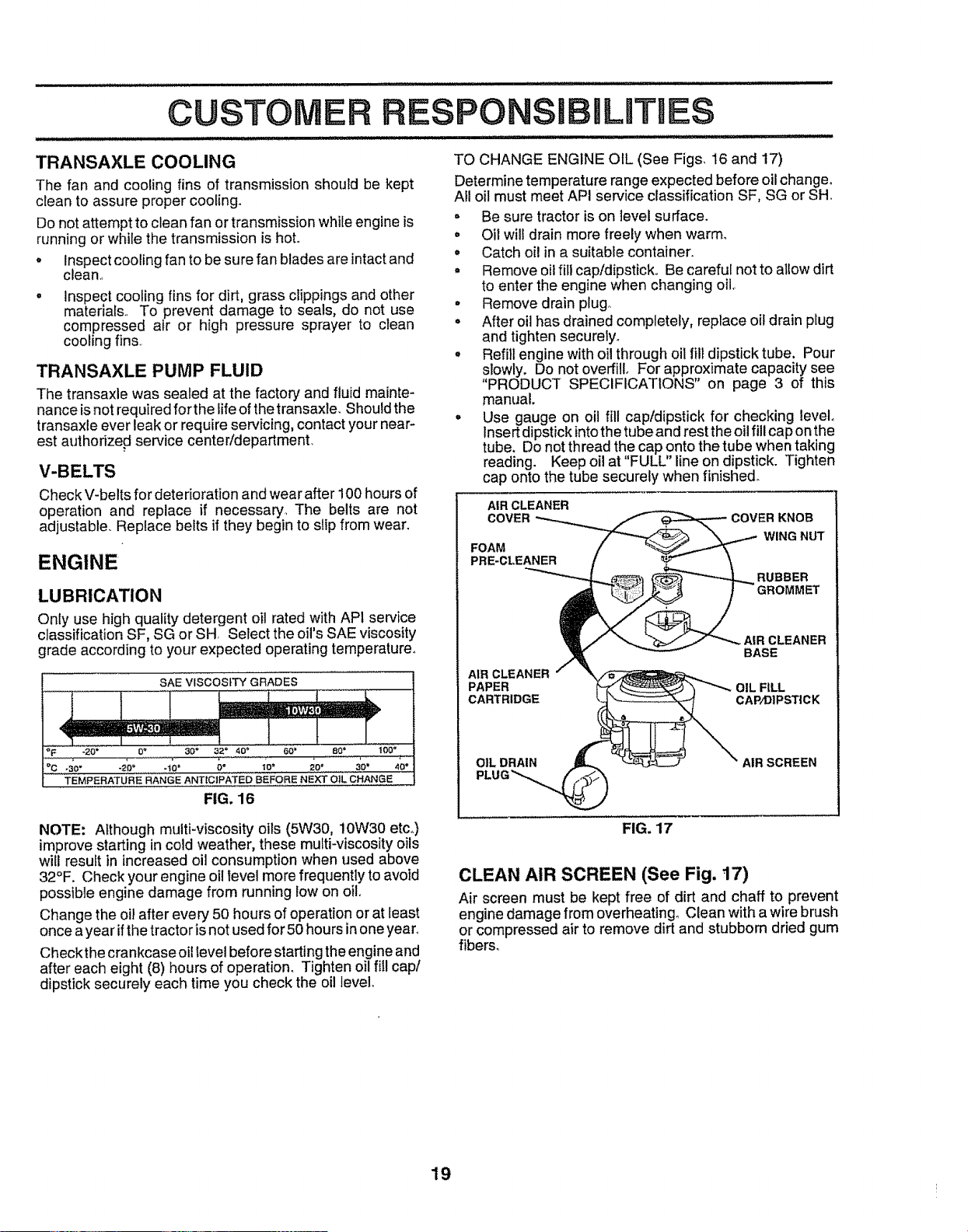
TO CHANGE ENGINE OIL (See Figs, 16 and 17)
Determine temperature range expected before oil change,
AII oil must meet API service classification SF, SG or SH
= Be sure tractor is on level surface.
o Oil will drain more freely when warm,
= Catch oil in a suitable container.
° Remove oil fill cap/dipstick, Be careful not to allow dirt
to enter the engine when changing oil,
• Remove drain plugo
• After oil has drained completely, replace oil drain plug
and tighten securely.
• Refill engine with oil through oil fill dipstick tube, Pour
slowly. Do not overfill. For approximate capacity see
"PRODUCT SPECIFICATIONS" on page 3 of this
manual.
° Use gauge on oil fill cap/dipstick for checking level°
Insert dipstick into the tube and rest the oil fill cap on the
tube. Do not thread the cap onto the tube when taking
reading. Keep oil at "FULL" line on dipstick. Tighten
cap onto the tube securely when finished.
AIR CLEANER
COVER
FOAM
PRE-Ct.EANER
KNOB
WING NUT
AIR CLEANER
BASE
AIR CLEANER
PAPER OIL FILL
CARTRIDGE CAP/DIPSTiCK
OIL DRAIN
PLUG_
AIR SCREEN
NOTE: Although multi-viscosity oils (5W30, i0W30 etc,,)
improve starting in cold weather, these multi-viscosity oils
will result in increased oil consumption when used above
32°F. Check your engine oil level more frequently to avoid
possible engine damage from running tow on oilo
Change the oil after every 50 hours of operation or at least
once a year if the tractor is not used for 50 hours in one year,
Checkthe crankcase oil level before starting the engine and
after each eight (8) hours of operation. Tighten oil fill cap/
dipstick securely each time you check the oil level,
FIG. 17
CLEAN AIR SCREEN (See Fig. 17)
Air screen must be kept free of dirt and chaff to prevent
engine damage from overheating. Clean with a wire brush
or compressed air to remove dirt and stubborn dried gum
fibers_
19
CUSTOMER R IBILITIES
AIR FILTER (See Fig. 17)
Your engine will not run properly using a dirty air filter°
Clean the foam pre-cleaner after every 25 hours of opera-
tion or every season° Service paper cartridge every 100
hours of operation or every season, whichever occurs first.
Service air cleaner more often under dusty conditions.
• Remove knob and cover.
° Remove wing nut and air cleaner from base_
TO SERVICE PRE-CLEANER
• Slide foam pre-cleaner off cartridge
• Wash it in liquid detergent and water.
• Squeeze it dry in a clean cloth. Allow it to dry.
• Saturate it in engine oil. Wrap it in clean, absorbent
cloth and squeeze to remove excess oil.
TO SERVICE CARTRIDGE
• Replace a dirty, bent, or damaged cartridgeo
NOTE: Do not wash the papercartridge or'use pressurized
air, as this will damage the cartridge.
= Reinstall the pre-cteaner (cleaned and oiled) over the
paper'cartridge.
• Reassemble air cleaner, wing nut, cover and tighten
knob secureiy_
CLEAN AIR INTAKE/COOLING AREAS
To insure proper' cooling, make sure the grass screen,
cooling fins, and other external surfaces of the engine are
kept clean at all times.
Every 100 hours of operation (more often under extremely
dusty, dirty conditions), remove the blower housing and
other cooling shrouds° Clean the cooling fins and external
surfaces as necessary. Make sure the cooling shrouds are
reinstalled.
NOTE: Operating the engine witha blocked grass screen,
dirty or plugged cooling fins, and/or cooling shrouds re-
moved will cause engine damage due to overheating_
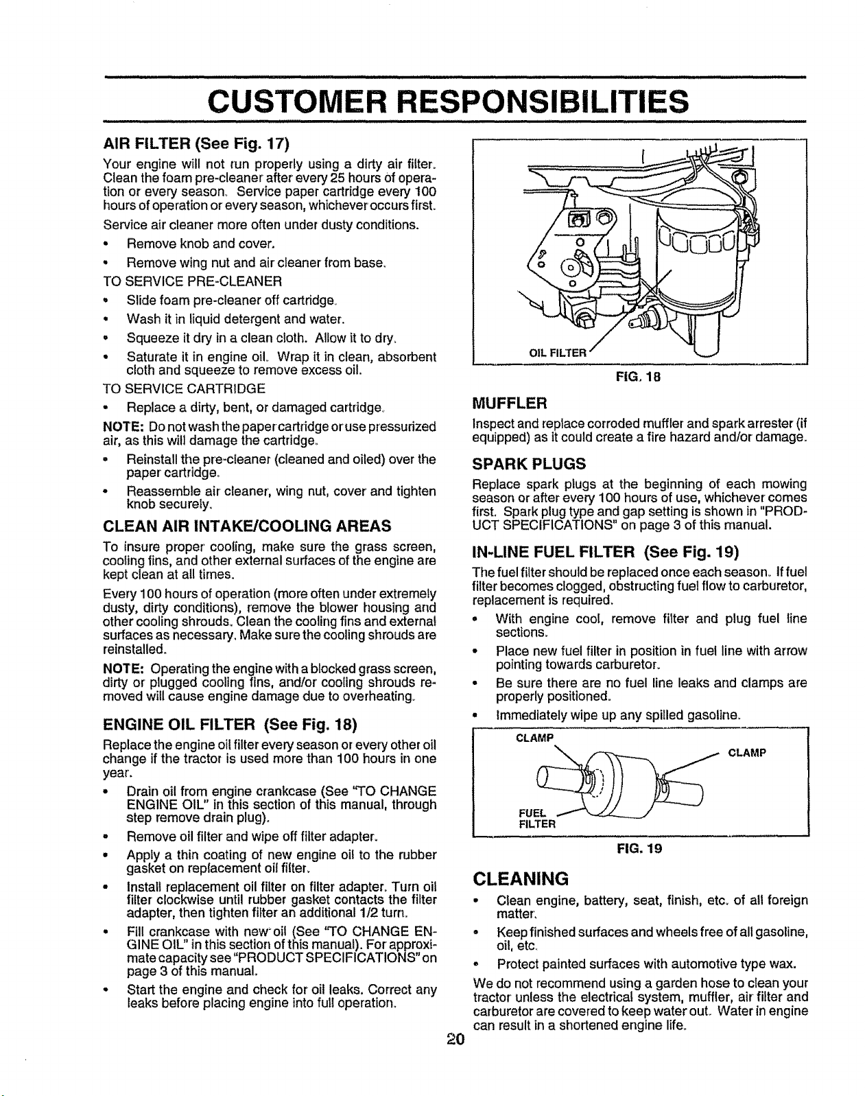
ENGINE OIL FILTER (See Fig. 18)
Replace the engine oil filter every season or every otheroil
change if the tractor is used more than 100 hours in one
year'.
° Drain oil from engine crankcase (See 'TO CHANGE
ENGINE OIL" in this section of this manual, through
step remove drain plug).
- Remove oil filter' and wipe off filter adapter.
° Apply a thin coating of new engine oil to the rubber
gasket on replacement oil filter,
• install replacement oil filter on filter adapter° Turn oil
filter clockwise until rubber gasket contacts the filter
adapter, then tighten filter an additional 1/2 turn.
° Fill crankcase with new'oit (See 'q'O CHANGE EN-
GINE OIL" in this section of this manual). For approxi-
mate capacitysee "PRODUCT SPECIFICATIONS" on
page 3 of this manual.
• Start the engine and check for oil leaks. Correct any
leaks before placing engine into futt operation.
I
FIG. 18
MUFFLER
Inspect and reptace corroded muffler and spark arrester (if
equipped) as it couldcreate a fire hazard and/or damage.
SPARK PLUGS
Replace spark plugs at the beginning of each mowing
season or after every 100 hours of use, whichever comes
first. Spark plug type and gap setting is shown in "PROD-
UCT SPECIFICATIONS" on page 3 of this manual.
IN-LINE FUEL FILTER (See Fig. 19)
The fuel filter should be replaced once each season_ If fuel
filter becomes clogged, obstructing fuel flow to carburetor,
replacement is required.
° With engine cool, remove fitter and plug fuel line
sections.
* Place new fuel filter in position in fuel line with arrow
pointingtowards carburetor_
• Be sure there are no fuel line leaks and clamps are
properlypositioned.
° Immediately wipe up any spilled gasoline,,
CLAMP
FUE__ CLAMP
FILTER
FIG, 19
2O
CLEANING
• Clean engine, battery, seat, finish, etc. of all foreign
matter'.
= Keep finished surfaces and wheels free of all gasoline,
oil, etc_
• Protect painted surfaces with automotive type wax.
We do not recommend using a garden hose to clean your
tractor unless the electrical system, muffler, air fitter and
carburetor are covered to keep water ouL Water in engine
can result in a shortened engine lifeo
i i_lr.l.i.
............. I,JIHIH,
SERVmCE AND ADJUSTMENTS
. i i i i...i..i, llll_ll_ll._ i . .i I'l'H"ll ""l"'ll',H I I" I _ I '
CAUTION; BEFORE PERFORMING ANY SERVICE OR ADJUSTMENTS:
• Depress clutch/brake pedal fully and set parking brake.
= Place motion control lever in neutral (N) position.
° Place attachment clutch in "DISENGAGED" position.
= Turn ignition key "OFF" and remove key.
o Make sure the blades and all moving parts have completely stopped.
Disconnect spark plug wire from spark plug and place wire where it cannot come in contact with
plug.
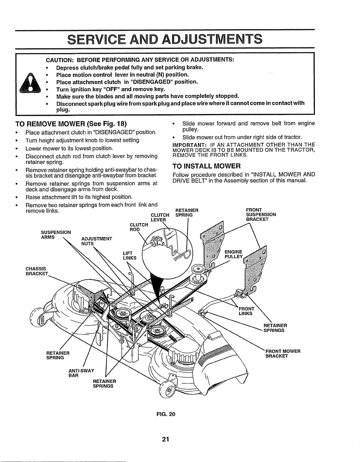
TO REMOVE MOWER (See Fig. 18)
, Place attachment clutch in "DISENGAGED" position_.
° Turn height adjustment knob to lowest setting.
o Lower mower to its lowest position_
, Disconnect clutch rod from clutch lever by removing
retainer spring.
o Remove retainer spring holding anti-swaybar to chas-
sis bracket and disengage anti-swaybar from bracket.
° Remove retainer springs from suspension arms at
deck and disengage arms from deck_
, Raise attachment tilt to its highest position..
° Remove two retainer springs from each front link and
remove tinkso
CLUTCH
LEVER
CLUTCH
ROD
SUSPENSION
ARMS ADJUSTMENT
NUTS
° Slide mower forward and remove belt from engine
pulleyo
• Slide mower out from under right side of tractor.
IMPORTANT; IF AN ATTACHMENT OTHER THAN THE
MOWER DECK IS TO BE MOUNTED ON THE TRACTOR.
REMOVE THE FRONT LINKS°
TO INSTALL MOWER
Follow procedure described in "INSTALL MOWER AND
DRIVE BELT" in the Assembly section of this manual.
RETAINER FRONT
SPRING SUSPENSION
BRACKET
LIFT
LINKS
ENGINE
PULLEY
CHASSIS
BRACKET
LINKS
RETAINER
-,SPRINGS
RETAINER
SPRING
ANTI-SWAY
BAR
RETAINER
SPRINGS
BRACKET
FIG. 20
21
AND ADJUSTMENTS
l llINNll, ............................................. I Lll =l=l= =l=l=l=l=l=l=,l=,I
TO LEVEL MOWER HOUSING
Adjust the mower while tractor is parked on level ground or
driveway. Make sure tires are properly inflated (See
"PRODUCT SPECIFICATIONS" on page 3 of this manual).
Iftires are over or underinflated, you will not properlyadjust
your mower_
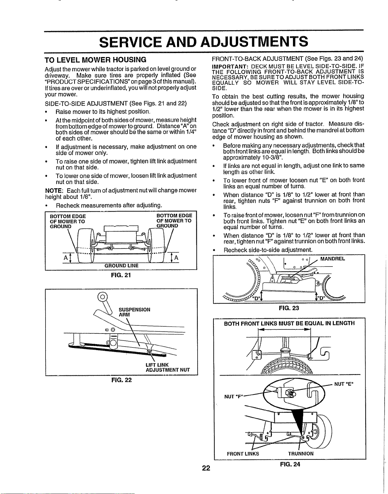
SIDE-TO-SIDE ADJUSTMENT (See Figs. 2i and 22)
• Raise mower to its highest position.
• At the midpoint of both sides of mower, measure height
from bottom edge of mower to ground. Distance"A" on
both sides of mower should be the same orwithin 1/4"
of each other.
° If adjustment is necessary, make adjustment on one
side of mower onfy.
° To raise one side of mower, tighten lift linkadjustment
nut on that side.
° To lower one side of mower', loosen lift linkadjustment
nut on that side.
NOTE: Each full turn of adjustment nut will change mower
height about 1/8".
• Recheck measurements after adjusting.
BOTTOM EDGE BOTTOM EDGE
OF MOWER TO OF MOWER TO
GROUND GROUND
GROUND LINE
FIG. 21
FRONT-TO-BACK ADJUSTMENT (See Figs. 23 and 24)
IMPORTANT: DECK MUST BE LEVEL SIDE-TO-SIDE. IF
THE FOLLOWING FRONT-TO-BACK ADJUSTMENT IS
NECESSARY, BE SURETO ADJUST BOTH FRONT LINKS
EQUALLY SO MOWER WILL STAY LEVEL SIDE-TO-
SIDE.
To obtain the best cutting results, the mower housing
should be adjusted so that the front is approximately 1/8" to
1/2" lower than the rear when the mower is in its highest
position.
Check adjustment on right side of tractor_ Measure dis-
tance"D" directly infront and behind the mandrel at bottom
edge of mower housing as shown.
• Before making any necessary adjustments, checkthat
both front links are equal in length. Both linksshould be
approximately 10-3/8".
° If links are not equal in length, adjust one link to same
length as other linko
° To lower front of mower loosen nut "E" on both front
links an equal number of turns°
° When distance "D" is 1/8" to 1/2" lower'at front than
rear, tighten nuts "F" against trunnion on both front
links.
° To raise front of mower, loosen nut"F" from trunnion on
both front links. Tighten nut "E" on both front links an
equal number of turns.
• When distance "D" is 1/8" to 1/2" lower at front than
rear, tighten nut"F" against trunnion on both front links.
• Recheck side-to-side adjustment.
MANDREL
SUSPENSION
ARM
LIFT LINK
ADJUSTMENT NUT
FIG. 22
22
FIG. 23
BOTH FRONTLINKS MUST BE EQUAL IN LENGTH
....... _
NUT "E"
NUT
FRONT LINKS
TRUNNION
FIG. 24

SERVmCE AND
TO REPLACE MOWER DRIVE BELT
MOWER DRIVE BELT REMOVAL (See Fig°25) -
o Parktractoron a levelsurface,,Engage parkingbrake°
Disengageattachmentclutchcontro!.
ADJUSTMENTS
TO REPLACE MOWER BLADE DRIVE BELT
(See Fig. 26)
Park the tractor on level surface_ Engage parking brake,
° Remove mower ddve belt (See'`TO REPLACE MOWER
• Remove four screws from Loll. mandrel cover and
remove cover,
° Roll belt over the top of L.H. mandrel pulley_
° Remove belt from engine puItey_
• Remove belt from idler pulleys_
° Remove any dirt or grass clippings which may have
accumulated around mandrels and entire upper deck
surface,
° Check primary idler arm and two idlers to see that they
rotate freely.
MOWER DRIVE BELT INSTALLATION (See Fig. 25) -
° Install belt in both idlers. Make sure belt is in both belt
keepers at the idlers as shown°
• Install new belt onto engine puIley.
° Ro!l belt into upper groove of L.H. mandrel pulley**
o Carefully check beit routing making sure belt is in the
grooves correctly and inside belt keepers.
• Reassemble LH. mandrel cover,,
SCREWS
LH. ENGINE
MANDREL IDLER PULLEY
COVER PULLEYS
MANDREL
MOWER
DRIVE
BELT BELT
KEEPERS
FIG. 25
DRIVE BELT" in this section of this manual).
Remove mower (See "TO REMOVE MOWER" in this
section of this manual)_
Remove four screws from R.Ho mandrel cover and
remove cover°
°
°
. Disconnect secondary clutch rod from pivot rod by
removing retainer spnng
o Carefully roll belt off R,,H. mandrel pulley.
. Remove belt from center mandrel pulley, idler pulley,
and L.H. mandrel pulley°
° Remove any dirt or grass which may have accumu-
lated around mandrels and entire upper deck surface.
- Check secondary idler arm and idler to see that they
rotate freely.
• Be sure spring is hooked in secondary idler arm and
sway-bar bracket.
o Install new belt in lower groove of L,,H.mandrel pulley,
idler pulley, and center mandrel pulley as shown.
• Roll belt over R_H.mandrel pulley. Make sure belt is in
all grooves properly.
° Reconnect secondary clutch rod to pivot rod with
retainer spring°
• Reinstall RoHomandrel cover.
o
Reinstall mower to tractor (See "INSTALL MOWER
AND DRIVE BELT" in the Assembly section of this
manual).
Reassemble mower drive belt (See "TO REPLACE
MOWER DRIVE BELT in this section of this manual)°
LH. MANDREL
MOWER CENTER
BLADE MANDREL
DRIVE BELT
SECONDARY
IDLER ARM
SPRING
g_N,
COVER
SWAY BAR
BRACKET
IDLER
PULLEY
SCREW
,,,,, ,,,,
FIG. 26
23
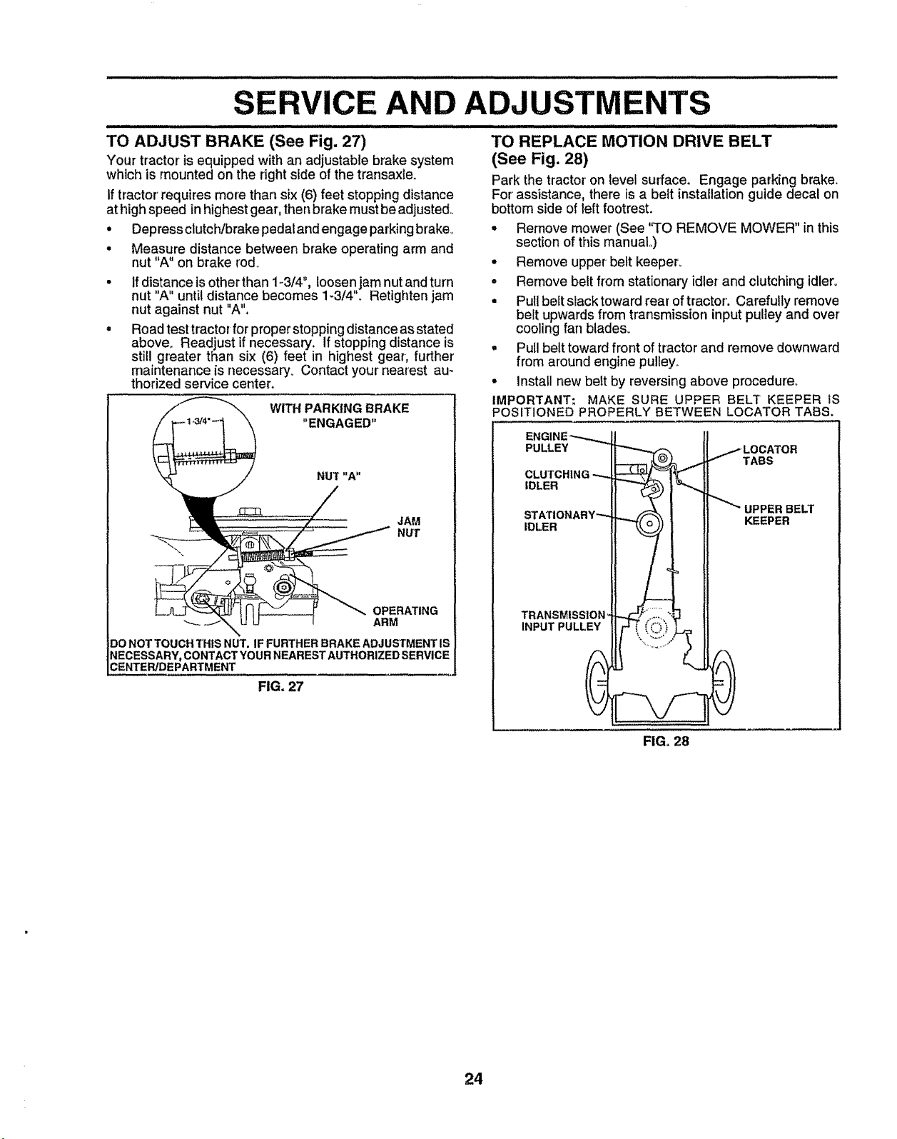
SERVICE AND ADJUSTMENTS
i
ii IIHI i i ii,lllll ii ill llll,,,,,,,,,,,, ,,, ,,,,,
TO ADJUST BRAKE (See Fig. 27)
Your tractor is equipped with an adjustable brake system
which is mounted on the right side of the transaxle.
If tractor' requires more than six (6) feet stopping distance
at high speed in highest gear, then brake must be adjusted,,
• Depress clutch/brake pedal and engage parking brake,,
Measure distance between brake operating arm and
nut "A" on brake rod.
If distance is other than 1-3/4", loosen jam nut and turn
nut "A" until distance becomes 1-3/4% Retighten jam
nut against nut "A".
Road test tractor for proper stopping distance as stated
above° Readjust if necessary. If stopping distance is
still greater than six (6) feet in highest gear, further
maintenance is necessary. Contact your nearest au-
thorized service center.
WITH PARKING BRAKE
"ENGAGED"
JAM
NUT
OPERATING
ARM
DONOTTOUCHTHISNUT. IFFURTHER BRAKEADJUSTMENT|S
NECESSARY, CONTACTYOURNEARESTAUTHORIZEDSERVICE
CENTERJDEPARTMENT
FIG. 27
i iiiilll.llllll i i ii i i illllll i i ii/ ii1/i ................ i, i ill,i
TO REPLACE MOTION DRIVE BELT
(See Fig. 28)
Park the tractor on level surface. Engage parking brake.
For assistance, there is a belt installation guide decal on
bottom side of left footrest.
• Remove mower (See "TO REMOVE MOWER" in this
section of this manual,,)
• Remove upper-belt keeper.
• Remove belt from stationary idler and clutching idler.
• Pull belt slack toward rear of tractor'. Carefully remove
belt upwards from transmission input pulley and over
cooling fan blades.
• Pull belt toward front of tractor and remove downward
from around engine pultey_.
• Install new belt by reversing above procedure.
IMPORTANT; MAKE SURE UPPER BELT KEEPER IS
POSITIONED PROPERLY BETWEEN LOCATOR TABS.
ENGINE _......_ II
PULLEY _'_ /LOCATOR
It-_ __ _TASS
CLUTCHING _--1'_
nDLER Jt _"_) I_"'-,,
II ! _ UPPER BELT
STATIONARY ......
IDLER IAP, Y_ r_=-'=H
TRANSMISStON_N_F ....._"_1
FIG. 28
24

SERVICE AND ADJUSTMENTS
TO ADJUST MOTION CONTROL LEVER TO ADJUST STEERING WHEEL ALIGNMENT
(See Fig. 29)
The motion control lever has been preset at the factory and
adjustment should not be necessary°
if for any reason the motion control lever will not hold its
position while at a selected speed, it may be adjusted at the
friction pack located on the right side of transmission°
• Park tractor on level surface° Stop tractor by turning
ignition key to "OFF" position, and engage parking
brake°
• Adjust motion control lever by tightening adjustment
locknut one half (1/2) turn.
NOTE; If for any reason the effort to move the motion
control lever becomes too excessive, reverse the above
adjustment procedure by loosening Iocknut 1/4 to 1/2 turn°
Road test tractor after adjustment and repeat procedure if
necessary°
ADJUSTMENT
LOCKNUT
If steering wheel crossbars are not horizontal (left to right)
when wheels are positioned straight forward, remove steer-
ingwheel and reassemble per instructions in the Assembly
section of this manual
FRONT WHEEL TOE-IN/CAMBER
The front wheel toe-in and camber are not adjustable on
your tractor. If damage has occurred to affect the front
wheel toe-in or camber, contact your nearest authorized
service center!department.
TO REMOVE WHEEL FOR REPAIRS
FRONT WHEEL (See Fig,,30) -
o Block up axle securely.
• Remove axle cover, retaining ring and washers to allow
wheel removal,
. Repair tire and reassemble.
° Replace washers and snap retaining ring securely in
axle groove.
= Replace axle cover,.
REAR WHEEL -
• Block rear axle securely°
• Remove five (5) hub bolts to allow wheel removal
o Repair tire and reassemble. Replace and tighten hub
bolts securely.
NOTE: To seal tire punctures and prevent flat tires due to
slow leaks, tire sealant may be purchased from your local
parts dealer. Tire sealant also prevents tire dry rot and
corrosion.
FIG, 29
TRANSMISSION REMOVAL/REPLACEMENT
Should your transmission require removal for service or
replacement, it should be purged after reinstaltation and
before operating the tractor. See "PURGE TRANSMIS-
SION" in Operation section of this manual
WASHERS
RETAINING
RING
AXLE COVER
!
SQUARE KEY
(REAR WHEEL ONLY)
FIG. 30
25

SERVICE AND ADJUSTMENTS
TO START ENGINE WITH A WEAK BATTERY
(See Fig, 32)
++..............................................
CAUTION: Lead=acid batteries gener-
ateexplosivegases, Keep sparks, flame
and smoking materials away from bat-
teries. Always wear eye protection
when around batteries.
..... iiiiiiiiii I
If your battery is too weak to start the engine, it should be
recharged+ If "jumper cables" are used for emergency
starting, follow this procedure:
IMPORTANT: YOUR TRACTOR IS EQUIPPED WITH A 12
VOLT NEGATIVE GROUNDED SYSTEM.+ THE OTHER
VEHICLE MUST ALSO BE A 12 VOLT NEGATIVE
GROUNDED SYSTEM. DO NOT USE YOUR TRACTOR
BATTERY TO START OTHER VEHICLES
TO ATTACH JUMPER CABLES -
• Connect each end of the RED cable to the POSITIVE
(+) terminal of each battery, taking care not to short
against chassis.,
• Connect one end of the BLACK cable to the NEGA-
TIVE (+)terminal of fully charged battery,.
° Connect the other end of the BLACK cable to good
CHASSIS GROUN D, away from fuel tank and battery.
TO REMOVE CABLES, REVERSE ORDER -
• BLACK cable first from chassis and then from the fully
charged battery+
° RED cable last from both batteries.
"POSITIVE" (+) "NEGATIVE" (-)
BOLT
/
TO REPLACE HEADLIGHT BULB
• Raise hood.
• Pull bulb holder out of the hole in the backside of the
grill+
° Replace bulb in holder and push bulb holder securely
back intothe hole in the backside of the grill+
° Close hood.
INTERLOCKS AND RELAYS
Loose or damaged wiring may cause your tractor to run
poorly, stop running, or+prevent it from starting+
• Check wiring. See electrical wiring diagram in the
Repair Parts section of this manual+
TO REPLACE FUSE
Replace with 30 amp automotive-type pLug-in fuse. The
fuse holder is located behind the dash+
TO REMOVE HOOD AND GRILL ASSEMBLY
(See Fig. 33)
• Raise hood.
• Unsnap headlight wire connector.
- Stand in front of tractor'. Grasp hood at sides, tilt toward
engine and riftoff of tractor+
° To replace, reverse above procedures+
HOOD
\
HEADLIGHT
WiRE
CONNECTOR
FIG. 33
FIG. 32
26

SERVICE AND ADJUSTMENTS
ENGINE
TO ADJUST THROTTLE CONTROL CABLE
(See Fig. 34)
The throttle control has been preset at the factory and
adjustment should not be necessary. Check adjustment as
described below before loosening cable. If adjustment is
necessary, proceed as follows:
o With engine not running, move throttle control lever
from slow (,,_!) to choke (N) position+ Slowly move
lever from choke (l\l) to fast ('_) position+
° Check to see if hole in throttte lever and hole in speed
control bracket are aligned.+
• If holes are not aligned, loosen cable clamp screw and
align the holes by inserting a pencil or a 1/4" drill bit
throughboth hotes.
° Pull throttle cable up to remove slack and tighten cable
clamp screw+ Remove alignment pencil or drill bit
TO ADJUST CARBURETOR (See Fig. 35)
The carburetor has been preset at the factory and adjust-
ment should not be necessary. However, minor adjust-
ment may be requiredto compensate for differences infuel,
temperature, altitude or load.. If the carburetor does need
adjustment, proceed as follows:
Jn general, turning the adjusting needles in (clockwise)
decreases the supply of fuel to the engine giving a leaner
fue!/air mixture+ Turning the adjusting needles out (counter-
clockwise) increases the supply of fuel to the engine giving
a richer fuel/air mixture..
IMPORTANT: DAMAGE TO THE NEEDLES AND THE
SEATS tN CARBURETOR MAY RESULT IF NEEDLE IS
TURNED IN TOO TIGHT.
NOTE: The carburetor on this engine is iow emission. It is
equipped with an idle fuel adjusting needle with a limiter
cap, which allows some adjustment within the limits allowed
by the cap+ Do not attempt to remove the limiter cap+ The
limiter cap cannot be removed without breaking the adjusting
needle.
• Be sure you have a clean air filter and the throttle
control cable is adjusted properly (see above)+
o Start engine and allow to warm for five minutes. Make
adjustments with engine running and shift/motion control
lever in neutral (N) position..
• Idle speed setting +With throttle control lever in slow
(,_) position, engine should idle at 1750 RPM+ If
engine idles too slow or fast, turn idle speed adjusting
screw in or out until correct idle is attained+
° Idle fuel needle setting + With throttle control lever in
slow (,_1_)position,turn idlefuel adjustment needle in
(clockwise) until engine begins to die and then turn out
(counterclockwise) until engine runs rough. Turn needle
+ !
to a point midway between ,hos8 ,h,_opositions.
• Recheck idle speed+ Readjust if necessary.
ACCELERATION TEST -
° Move throttle control tever from slow (_) to fast ('¢/_)
position+ If engine hesitates or dies, turn idle fuel
adjusting needle out (counterclockwise) 1/8 turn, Re-
peat test and continue to adjust, if necessary, until
engine accelerates smoothly,,
High speed stop is factory adjusted, Do not adjust -
damage may result+
IMPORTANT: NEVER TAMPER WITH THE ENGINE
GOVERNOR, WHICH IS FACTORY SET FOR PROPER
ENGLNE SPEED OVERSPEEDING THE ENGINE ABOVE
THE FACTORY HIGH SPEED SETTING CAN BE
DANGEROUS+ IFYOU THINKTHE ENGINE-GOVERNED
HIGH SPEED NEEDS ADJUSTING, CONTACT YOUR
NEAREST AUTHORIZED SERVICE CENTER/
DEPARTMENT, WHICH HAS PROPER EQUIPMENT AND
EXPERIENCE TO MAKE ANY NECESSARY
ADJUSTMENTS,
CABLE
CLAMP
BRACKET
FIG. 34
THROTTLE
LEVER
IDLE SPEED
ADJUSTING
IDLE FU
ADJUSTING
NEEDLE
FIG, 35
27
immediately prepare your tractor' for storage at the end of
the season or if the tractor will not be used for 30 days or
mo re
I X CAUTION: Never store the tractor with !
| • • gasoline in the tank inside a building !
| _ where fumes may reach an open flame |
| U or spark. Allow the engine to cool I
! before storing in any enclosure. !
TRACTOR
Remove mower from tractor for winter storage.. When
mower is to be stored for a period of time, clean it thor-
oughiy, remove all dirt, grease, leaves, etc. Store in a
clean, dry area,
• Clean entire tractor (See"CLEANING" in the Customer
Responsibilities section of this manual).
• Inspect and replace belts, if necessary (See belt re-
placement instructionsin the Service and Adjustments
section of this manual).
Lubricate as shown in the Customer Responsibilities
section of this manual.
I
m
Be sure that all nuts, bolts and screws are securely
fastened. Inspect moving parts for damage, breakage
and wear. Replace if necessary.
Touch up all rusted or chipped paint surfaces; sand
_ightlybefore painting°
BATTERY
• Fully charge the battery for storage.
. After a period of time in storage, battery may require
recharglng_
° To help prevent corrosion and power leakage during
long periods of storage, battery cables should be
disconnected and battery cleaned thoroughly (see "TO
CLEAN BATTERY AND TERMINALS in the Cus-
tomer Responsibilities section of this manual).
• After' cleaning, leave cables disconnected and place
cables where they cannot come in contact with battery
terminals.
• Be sure battery drain tube is securely attached.
, If battery is removed from tractor for storage, do not
store battery directly on concrete or damp surfaces.
ENGINE
FUEL SYSTEM
IMPORTANT: 1T IS IMPORTANT TO PREVENT GUM
DEPOSITS FROM FORMING IN ESSENTIAL FUEL
SYSTEM PARTS SUCH AS CARBURETOR, FUEL FILTER,
FUEL HOSE, OR TANK DURING STORAGE. ALSO,
EXPERIENCE INDICATES THAT ALCOHOL BLENDED
FUELS (CALLED GASOHOL OR USING ETHANOL OR
METHANOL) CAN ATTRACT MOISTURE WHICH LEADS
TO SEPARATION AND FORMATION OF ACIDS DURING
STORAGE. ACIDIC GAS CAN DAMAGE THE FUEL
SYSTEM OF AN ENG(NE WHILE _N STORAGE.,
° Drainthe fueltank.
• Start the engine and let it run until the fuel lines and
carburetor are empty.
• Never use engine or carburetorcleaner products in the
fuel tank or permanent damage may occur.
° Use fresh fuel next season_
NOTE: Fuel stabilizer is an acceptable alternative in
minimizing the formation of fuel gum deposits during stor-
age. Add stabilizer to gasoline in fuel tank or storage
container. Always follow the mix ratio found on stabilizer
container. Run engine at least 10 minutes after' adding
stabilizer to allow the stabilizer to reach the carburetor. Do
not drain the gas tank and carburetor if using fuel stabilizer.
ENGINE OIL
Drain oil (with engine warm) and replace with clean engine
clio (See "ENGINE" in the Customer Responsibilities
section of this manual).
CYLINDERS
• Remove spark plug(s).
° Pour one ounce of oil through spark plug hole(s) into
cylinder(s)o
° Turn ignitionkeyto"START" positionfor a few seconds
to distribute oil
° Replace with new spark plug(s).
OTHER
• Do not store gasoline from one season to another_
• Replace your'gasoline can if your can starts to rust.
Rust and/or dirt in your gasoline will cause problems.
• If possible, store your tractor indoors and cover it to
give protection from dust and dirt.
• Cover your'tractor with a suitable protective covetthat
does not retain moisture. Do not use plastic. Plastic
cannot breathe which allows condensation to form and
will cause your tractor to rust.
IMPORTANT: NEVER COVER TRACTOR WHILE ENGINE
AND EXHAUST AREAS ARE STILL WARM_
28

PROBLEM
mn,l,rmHi i
Will not start
Hard to start
Engine wilt not turn over
Engine clicks but will not
start
Loss of power
Excessive vibration
CAUSE
to Out offue_
2 Engine not"CHOKED" proper{y,
3. Engine flooded.
4. Bad spark plug.
5, Dirty air filter.
6, Dirty fuel filter,
7_ Watertn fuel.
8. Loose or damaged w[dng
9,, Carburetor out of adjustment.,
10. Engine vatves out of adjustment.
1. D]rtyalrffiter
2, Bad spark plug,
3. Weak or dead battery,
4, Dirty fuel filter.,
5, State or dirty fuel
6, Loose or damaged wfdng.
7. Carburetor out of adjustment•
CORRECTION
t,, Fifi fuel tank,
2. See "TO START ENGINE" in Operation section,
3. Wait several minutes before attempting to start
4 Replace spark plug,
5, Clear,Jreplace air filter.
6, Replace fuel f{Iter.
7. Drain fuel tank and carburetor, refill tank with fresh
gasoline and replace fuel filter.,
8, Check all wiring
9, See "To Adjust Carburetor" in Service Adjustments
section.
10 Contact an authorized service centerldepartment.
B, Engine valves out of adJuslmenL
1. CiutchJbrakepedal net depressed,
2. Attachment dutch is engaged,,
3., Weak or dead battery,
4. Blown fuse°
5_ Corroded battery terminals.
6. Loose or damaged wiring.
7. Faulty ignition switch,,
B. Faulty solenoid or starter.
9, Faulty operator presence switch(as},
I, Weak or dead battery.,
2. Corroded battery terminals.,
3, Loose or damaged wiring,
4. Faulty solenoid or starter,,
1, Cutting too much grassttoo fast.
2 ThrotUe in "CHOKE" position.
3 Build-up of grass, leaves and trash under mower,
4, Dirty air fitter.
5, Low ofl level/dirty ell
6. Faulty spark plugo
7, Dirty luel filter_
8. State or dirty fuel,
9. Water in fuel,
10- Spark plug wire loose,
11,, Dirty engine atr screen!fins.
12 Dtrtylclogged muffler
13, Loose or damaged wking.,
14 Carburetor out of adjustment.
1, Clean/replace air filter
2. Replace spark plug,
3, Recharge or replace battery.
4. Replace fuel filter,
5, Drain fuel tank and refill with fresh gasoline
6 Check all wiring,
7. See "To Adjust Carburetor' _nService Adjustments
section,
8° Contact an authorized service centertdepartment,
1, Depress clutch/brake pedal
2. Disengage attachment clutch,
3 Recharge or replace battery,
4. Reptace fuse,
5, Clean battery terminate
6_ Checkaffwlring
7., Check/replace ignitionswitch.,
8. Check/replace soteno{d or starter,
9, Contact an authorized service center/department
1 Recharge or replace battery_
2. Clean battery term(naBs,
3. Check all wtdng,
4. Check/replace solenoid or starter.
t, Set in "Higher Cut" positiorv'reduce speed_
2. Adjust throttle control,
3. Clean underside of mower housing.
15 Englne valves out of adjustment,
1, Worn, bent or loose b!ede,
2, Bent blade mandrel,
3 Loose/damaged part(s).
4. CleanirepIace air filter.
5 Check oil levee/change oil,
6. Clean and regap or change spark plug
7, Replace fuel litter.
8 Drain fuet tank and refill with fresh gasoline,
9. Drain fuel tank and carburetor, refill tank with fresh
gasoline and replace fuel filter,
I 0o Connect and tighten spark pfug wire,
!1. C{ean engine air screen/fins,
12. Clean/replace muffler.
13. Check all wiring,
14. See "To Adjust Carburetor" in Service Adjustments
section
15, Contact an authorized service centerfdepartment,
1 Replace blade, Tighten blade bolt,
2 Replace blade mandrel.
3. Tighten loose part(s). Replace damaged parts
29
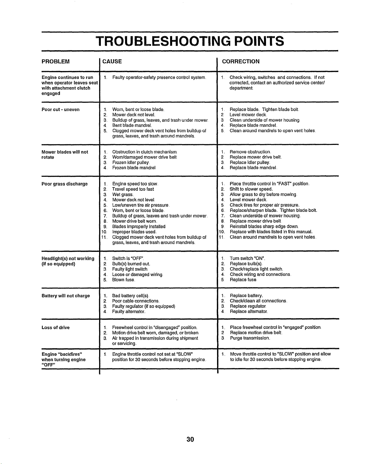
UIUjIUIIII_IIIllUIIlllIllmlllll I Ill II I
Engine continues to run
when operator leaves seat
with attachment clutch
engaged
.... illl
Poor cut - uneven
Mower blades wilt not
rotate
Poor grass discharge
Headlight(s) not working
(if so equipped)
Battery will not charge
Loss of drive
illlllll_l_ illll i]ll ill iiii illl IH
Engine "backfires"
when turning engine
"OFF"
CAUSE
iltltl i iiittt
1, Faulty operator_safety presence control system,
1, Worn, bent or Ioose blade.
2. Mower deck not level.,
3, Buildup of grass, leaves, and trash under mower
4, Bent blademandrel
5. Clogged mower deck vent holes from buildup of
grass, leaves, and trash around mandrels_
1, Obstruction in dutch mechanism
2, Womldamaged mower drive belt
3 Frozen Idler pulley,
4. Frozen blade mandrel
1, Engine speed too siow_
2, Travel speed too fast,
3. Wet grass.
4. Mower deck not Ievel
5, Lowfuneven tire air pressure,
6, Worn, bent or loose blade,
7. Buildup of grass, leaves and trash under mower.
8 Mower drive belt worn
9, Blades Improperly instaIIed
10, Improper blades used,
11, Clogged mower deck vent holes from buitdup of
grass, leaves, and trash around mandrels.
1, Switch is "OFF",
2 Bulb(s) bumed out,.
3 Faulty light switch
4, Loose or damaged wiring,
5, Blown fuse_
1. Bad battery ceil(s).
2, Poor cable connections.
3. Faulty regulator (if so equipped)
4. Faulty alternator,.
1, Freewheel control in "disengaged" position.
2. Motion ddvs belt worn, damaged, or broken.
3, Air trapped in transmission during shipment
or serviclng,_
1 Engine throttle control not set at "SLOW"
position for 30 seconds before stopping engine
CORRECTION
i= =l Mn,_ :HHI tl ,, JlIJI .....
1 Check wiring, switches and connections_ if not
corrected, contact an authorized service center/
department,
1, Replace brads. TIghten blade bolt
2 Level mower deck,
3 Clean underside of mower housing
4, Replace blade mandrel,
5, Clean around mandrels to open vent holes,
1, Remove obstr,_ction,
2 Replace mower drive belt,
3 Replace Idler pulley,
4. Replace blade mandrel,
1. Place throtUe control in "FAST" position,
2. Shift to slower speed.
3 Allow grass to dry before mowing
4, Level mower deck,
5, Check tires for proper air pressure.
6, Repiacelsharpen blade. Tighten blade bolt,,
7,. Clean underside of mower housing,
8 Replace mower drive belt
9 Reinstall blades sharp edge down,
10. Replace with blades listed in this manual.
11 Clean around mandrels to open vent holes,
1, Turn switch "ON"_
2. Replace bufb(s),
3. Check/replace light switch,
4. Check wiring and connections,
5 Replace fuse.
1, Replace battery_
2, Check/clean all connections,
3 Replace regulator
4, Replace alternator,
I, Place freewheel control in "engaged" position,
2 Replace motion drive belt,
3 Purge transmission,
1, Move throttle control to "SLOW" position and allow
to idle for 30 seconds before stopping engine,
30
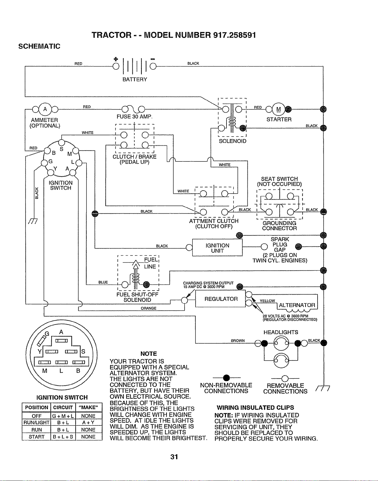
TRACTOR - - MODEL NUMBER 917.258591
SCHEMATIC
RED
BATTERY
BLACK
AMMETER
(OPTIONAL)
!
IGNITION
SWITCH
RED
WHITE
FUSE30 AMP.
r
I _ I
,©: ©',
I
BLACK
i
I
I
I I
I I
SOLENOID
WHITE
STARTER
BLACK
WHITE
I
I
I r
BLUE
BLACK
r J ORANGE
r !
i ._FUELI
, L,NE'
! 1
FUELSHUT-OFF
SOLENOID
ATT'MENT CLUTCH
(CLUTCH OFF)
C-_ IGNITIONUNIT
SEAT SWITCH
(NOT OCCUPIED)
|
f .... 1 1
GROUNDING
CONNECTOR
_ SPARK
PLUG
GAP '_ "
PLUGS ON
N CYL ENGINES)
CHARGING SYSTEM OUTPUT
t5 AMP DC @ 3600 RPM Q
28 VOLTS AC @ 3600 RPM
(REGULATOR DISCONNECTED)
IGNITION SWITCH
POSITION CIRCUIT "MAKE"
OFF G + M + L NONE
RUNIUGHT B + L A + Y
RUN B + L NONE
START B + L + S NONE
NOTE
YOUR TRACTOR IS
EQUIPPED WITH A SPECIAL
ALTERNATOR SYSTEM.
THE LIGHTS ARE NOT
CONNECTED TO THE
BATTERY, BUT HAVE THEIR
OWN ELECTRICAL SOURCE.
BECAUSE OF THIS, THE
BRIGHTNESS OF THE LIGHTS
WILL CHANGE WITH ENGINE
SPEED. AT IDLE THE LIGHTS
WILL DIM. AS THE ENGINE IS
SPEEDED UP, THE LIGHTS
WILL BECOME THEIR BRIGHTEST.
BROWN
HEADLIGHTS
NON-REMOVABLE
CONNECTIONS
REMOVABLE /-_
CONNECTIONS
WIRING INSULATED CLIPS
NOTE: IF WIRING INSULATED
CLIPS WERE REMOVED FOR
SERVICING OF UNIT, THEY
SHOULD BE REPLACED TO
PROPERLY SECURE YOUR WIRING°
31
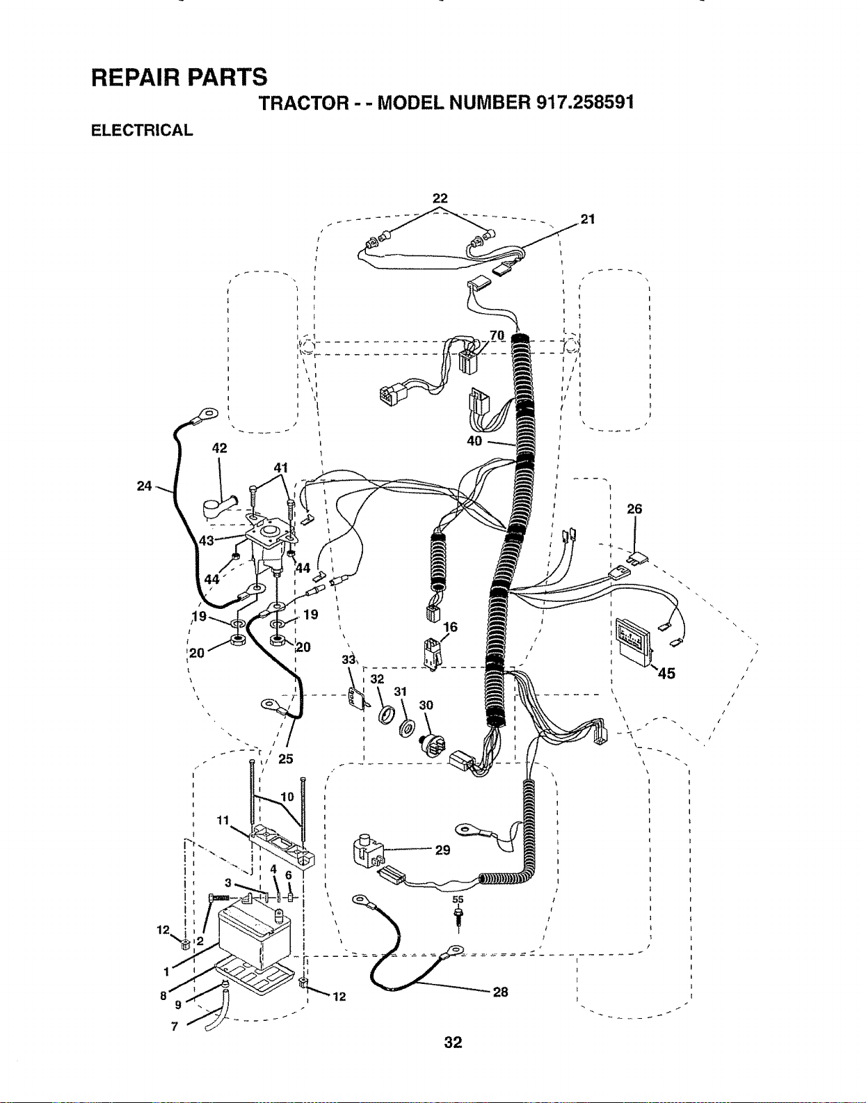
REPAIR PARTS
TRACTOR -- MODEL NUMBER 917.258591
ELECTRICAL
24
42
6
I
19
' i6
3O
26
I
t
!
\
\
\
{
}
12 _
32

REPAnR PARTS
TRACTOR - - MODEL NUMBER 917.258591
ELECTRICAL
KEY PART
NO. NO. DESCRIPTION
1 144926
2 74760412
3 STD551025
4 STD551125
6 STD541025
7 7697J
8 7603J
9 109596X
10 145211
11 150109
12 145769
16 153664
19 STD551125
20 73350400
21 I36850
22 4t52J
24 146136
25 146148
26 108824X
28 145491
29 121305X
30 140301
31 12421iX
32 141226
33 109310X
40 156149
41 71110408
42 131563
43 145673
44 73640400
45 122822X
55 17490508
70 140426
Battery 12 Volt 30 Amp
Bolt, Hex Head 1/4-20 unc x 3/4
Washer
Washer
Nut
Tube, Plastic, 46"
Tray, Battery
Clamp, Hose
Bolt BTR FRT 1-4-20 x 7_5
Holddown Battery
Nut, Push Nylon 1/4 Bat. Frt.
Switch Interlock Push-In
Washer, Lock
Nut, Hex, Jam 1/4-20 UNC
Harness, Light Socket
(includes 4t52J)
Bulb, Light
CabIe, Battery, Gauge, Red, 24"
Cabre, Battery, 66
Red, Wi
Gauge,
16 Wit 22"
Fuse, 30 Amp
Cable, Ground, 6 Gauge, Black, 21"
Switch, Plunger
Switch, Ignition
Nut, Ignition
Cover, Key Switch
Key, Ignition
Harness, Ignition
Bolt, Hex Head, Fin. 1/4-20 x 1/2
Cover, Terminal, Red
SoIenoid
Nut Keps BIk Hex I/4-20 UNC
Ammeter Rectangular 15 Amp
Screw, Thdrol 5/16-18 x 1/2
Harness Engine Koh Cmd-L 15AR
NOTE: All component dimensions given in U.S. inches
1 inch = 25..4 mm
33
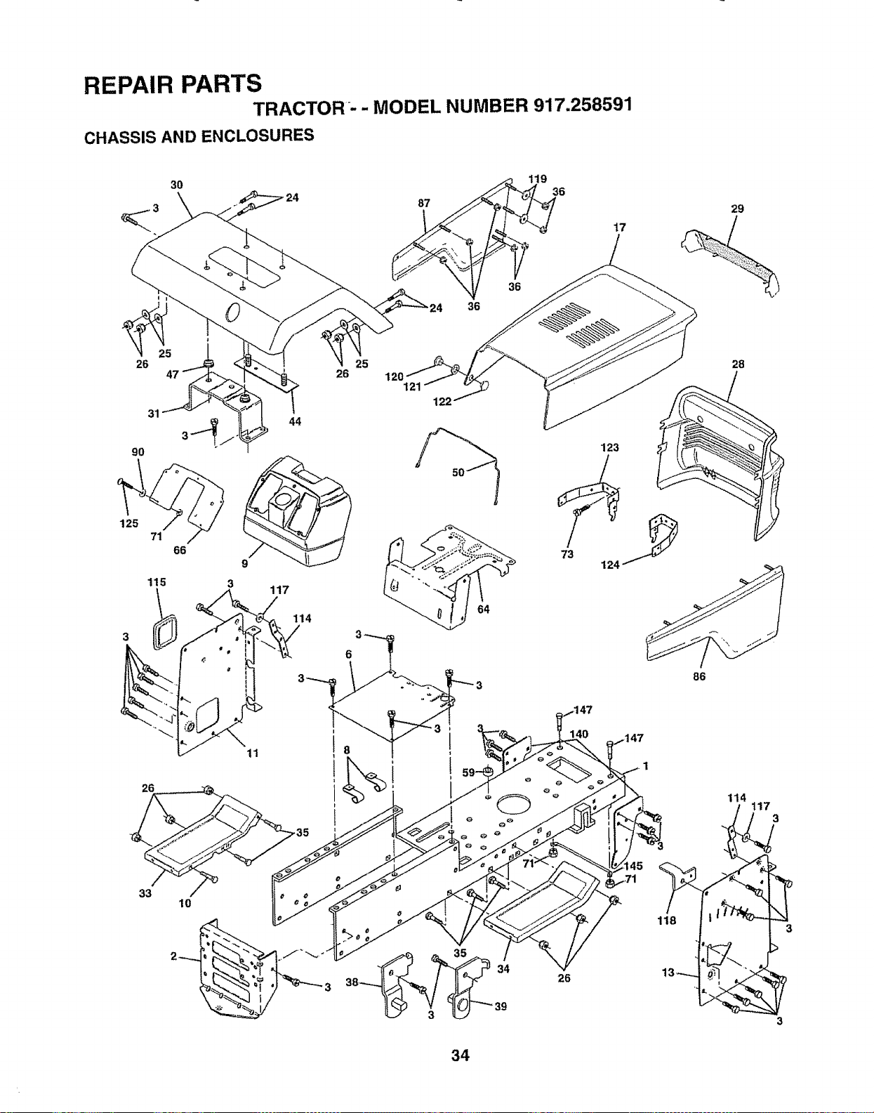
REPAIR PARTS
TRACTOR _-- MODEL NUMBER 917.258591
CHASSIS AND ENCLOSURES
30
\
26
125
71
66
115 3
26
33
10
6
8
36
17
29
25
26
121
28
44
117
114
6 3
i '
T
123
86
140
26
47
1
118
114
3
3
34
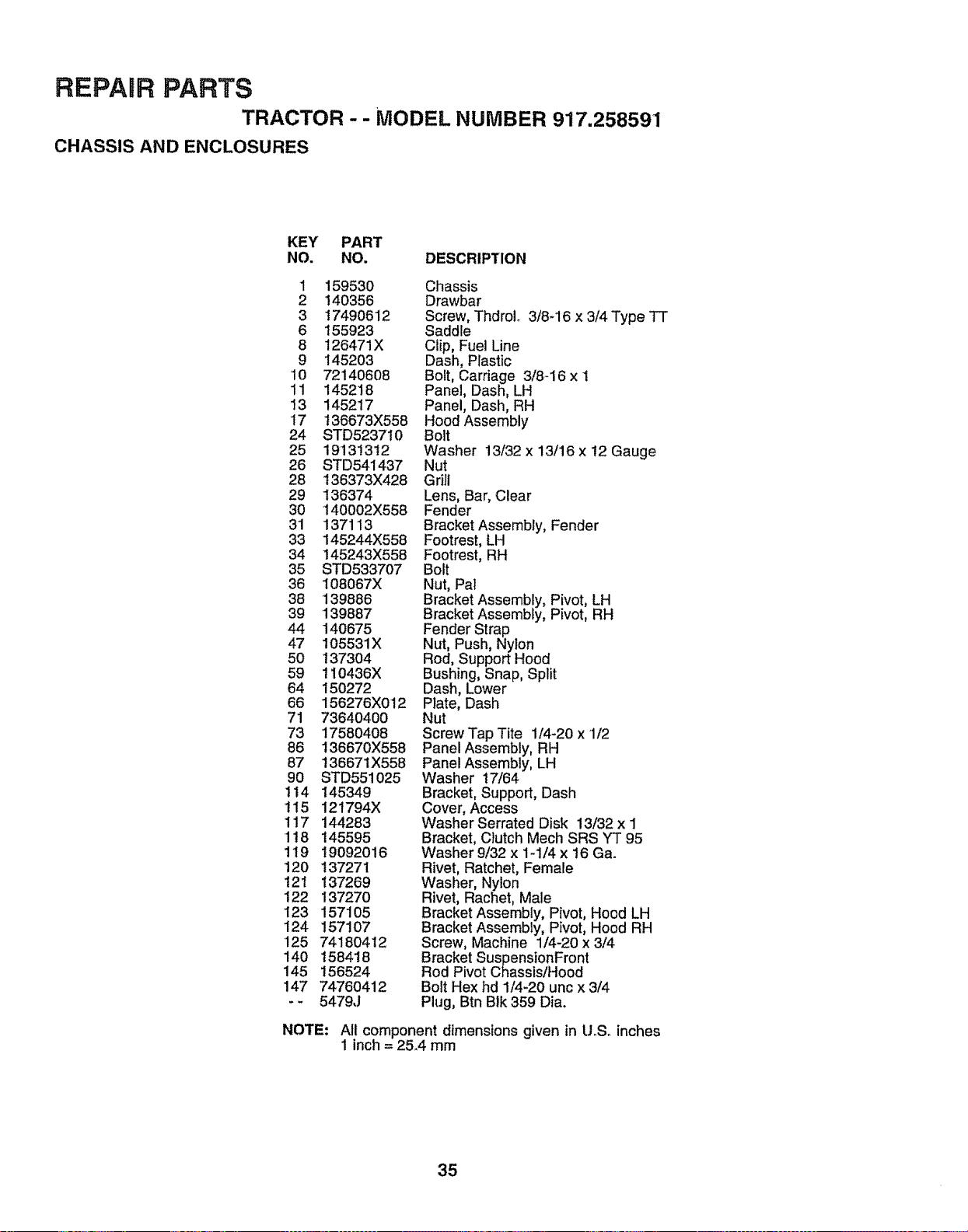
REPAIR PARTS
TRACTOR - - MODEL NUMBER 9"17.258591
CHASSIS AND ENCLOSURES
KEY PART
NO. NO. DESCRIPTION
1 159530 Chassis
2 140356 Drawbar
3 !7490612 Screw, ThdroL 3/8-16 x 3/4 Type TT
6 155923 Saddle
8 I26471X Clip, Fuel Line
9 I45203 Dash, Plastic
10 72140608 Bolt, Carriage 3/8-16 x 1
11 145218 Panel, Dash, LH
13 145217 Panel, Dash, RH
17 t36673X558 Hood Assembly
24 STD523710 Bolt
25 191313t2 Washer 13/32 x 13/16 x t2 Gauge
26 STD541437 Nut
28 t36373X428 Grill
29 136374 Lens, Bar, Clear
30 140002X558 Fender
31 137113 Bracket Assembly, Fender
33 145244X558 Footrest, LH
34 145243X558 Footrest, RH
35 STD533707 Bolt
36 I08067X Nut, Pal
38 139886 Bracket Assembly, Pivot, LH
39 139887 Bracket Assembly, Pivot, RH
44 140675 Fender Strap
47 105531X Nut, Push, Nylon
50 t37304 Rod, Support Hood
59 t10436X Bushing, Snap, Split
64 150272 Dash, Lower
66 156276X012 Plate, Dash
71 73640400 Nut
73 17580408 Screw Tap Tite 1/4-20 x 1/2
86 136670X558 Panel Assembly, RH
87 136671X558 PanelAssembly, LH
90 STD55i025 Washer 17/64
114 145349 Bracket, Support, Dash
't15 121794X Cover, Access
117 144283 Washer Serrated Disk 13/32 x 1
•118 145595 Bracket, Clutch Mech SRS YT 95
1t9 19092016 Washerg/32x 1-1/4x 16 Ga.
120 137271 Rivet, Ratchet, Female
121 137269 Washer, Nylon
122 137270 Rivet, Rachet, Male
123 157105 Bracket Assembly, Pivot, Hood LH
124 157107 Bracket Assembly, Pivot, Hood RH
125 74180412 Screw, Machine 1/4-20 x 3/4
140 1584!8 Bracket SuspensionFront
145 156524 Rod Pivot Chassis/Hood
147 74760412 Bolt Hex hd 1/4-20 unc x 3/4
- - 5479J Plug, Btn BIk 359 Dia.
NOTE:
Aft component dimensions given in I.LSoinches
1 inch = 25_4 mm
35
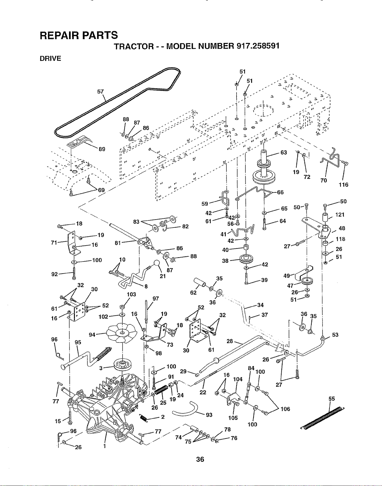
FIEPAIFIpARTS
.TRACTOR
. . t_oOEL t4UNIBP-.B917.256591
77
36
53
55

REPAIR PARTS
TRACTOR - - MODEL NUMBER 917.258591
DRIVE
KEY PART KEY PART
NO. NO. DESCRIPTION NO. NO,
1 150071 Transaxle (See Breakdown) Hydro 63 140186
Gr Model310-0650 64 71170764
2 142431 Spring, Return, Brake 65 STD551143
3 143995 Pulley, Transaxle 66 154778
8 141002 Rod Shift Hydro LT 69 142432
10 76020416 Pin Cotter 1/8x ! CAD 70 156470
15 74490544 Bolt Hex FIghd 5/16-t8 Gr,.5 71 140158
16 73800500 Nut Lock HexW/tnso 5/16-18 Unc 72 19132012
18 74780616 Bolt Fin Hex 3/8-16 Unc x 1 Gr. 5 73 156347
i9 73800600 Nut Lock HexW/Wsh 3/8-16 Uric 74 121199X
21 130564 Knob, Deluxe 1/2-13 75 121749X
22 145627 Rod, Brake Hydro 76 12000001
24 73350600 Nut, Hex Jam 3/8-t6 Unc 77 !23583X
25 106888X Spring, Brake Rod 78 I21748X
26 19131316 Washer 81 '140154
27 76020412 Pin Cotter 1/8 x 3/4 CAD. 82 123782X
28 145204 Rod, Parking Brake 83 19171216
29 124236X Cap, Parking Brake 84 140548
30 130807 Bracket, Transaxle 86 71208
32 74760512 Bolt Hex Hd 5/16_18 Uncx3!4 87 19212016
34 155071 Shaft, Foot Pedal 88 12000008
35 120183X Bearing, Nylon 89 151146
36 19211616 Washer 91 74780536
37 t572H Pin, Roll 92 74780524
38 t23674X Pulley, Idler, Flat 93 142564
39 74760644 Bolt 94 140462
40 4470J Spacer, Split 95 144643
41 154777 Keeper, Belt Idler 96 4497H
42 19131312 Washer 13/32 x t3/16x i2 Gauge 97 140469
47 127783 Pulley, Idler, V-Groove 98 73510600
48 154604 BellcrankAssembly 100 19111216
49 123205X Retainer, Belt 102 141322
50 74760624 Bolt 103 73940800
51 73680600 Nut Crowntock 3/8-16 UNC 104 140156
52 73680500 Nut, Crownlock 5/16-18 Unc 105 71070516
53 105710X Link, Clutch 106 74780520
55 105709X Spring, Return, Clutch 116 72110610
56 74760620 Bolt Hex 3/8d6x 1-1/4 118 154774
57 140294 V-Belt, Ground Drive 121 154419
59 140312 Keeper, Center Span
61 17490612 Screw ThdroL 3/8-16 x 3/4 Ty.."IT
62 8883R Cover, Pedal
DESCRIPTION
Pulley, Engine
Bolt Hex
Washer
Keeper Belt Engine
Screw
Keeper Belt Engine
Strap Torque Lh Hydro 18/20" T
Washer 13/32 x 1-1/4 x 12 Gauge
Strap Torque Rh Hydro 18/20" T
Spacer, Split
Washer 25/32 x 1-1/4 x 16 Gauge
E-Ring
Key, Square
Washer 25/32 x 1-5/8 x 16 Gauge
Shaft Asm.. Cross Hydro 20" Tires
Spring Torsion T/A
Washer 17/32 x 3/4 x 16 Gao
Rod, Tie Hydro 20" Tires
Bushing Rod Stdgo 629/632 tD
Washer 21/32 x 1-1/4 x 16 Gao
Ring Klip #5304-62
Console, Shift
Bolt Fin Hex 5/t6-18 x 2d/4
Bolt Fin Hex 5/6-18 Unc x 1-1/2
Line Fuel Hydro 4"
Fan, Hydro 7"
Control Bypass Hydro 20" Tires
Retainer Spring 1" Zinc/Cad
Keeper Bolt Rh Hydro 0750. 18/20"
Nut Keps Hex 3/8-16 Uric
Washer 11/32 x 3/4 x 16 Ga.
Washer Bellville °501D x 1.50D
Nut Hex Jam Toplock 1/4-20 Unf
Arm, Control Hydro
Screw Cap Hex 5t16 x 18 x 1
Bott Fin Hex 5/16-18 Unc x 1-1/4
Bolt Rdhd Sq Neck 3/8-16 x 1_25
Spacer Beltcrank
Nyliner Clutching STL
NOTE" All component dimensions given in U.S. inches
1 inch = 25.4 mm
37
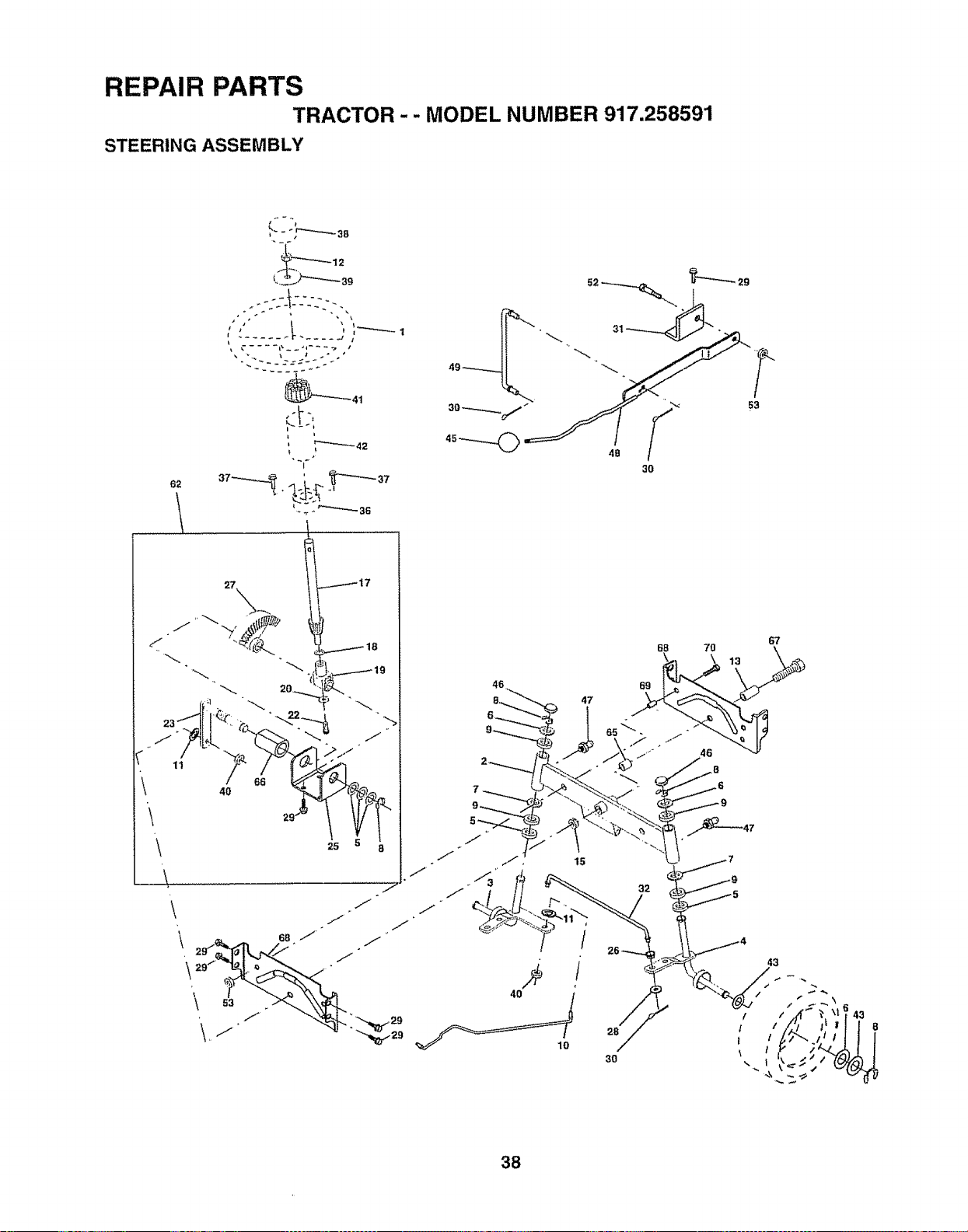
REPAIR PARTS
TRACTOR -- MODEL NUMBER 917,258591
STEERING ASSEMBLY
62
t #"
.... _41
t i
I
29
53
67
68 70 \
15
40
lO
32
28
30
38
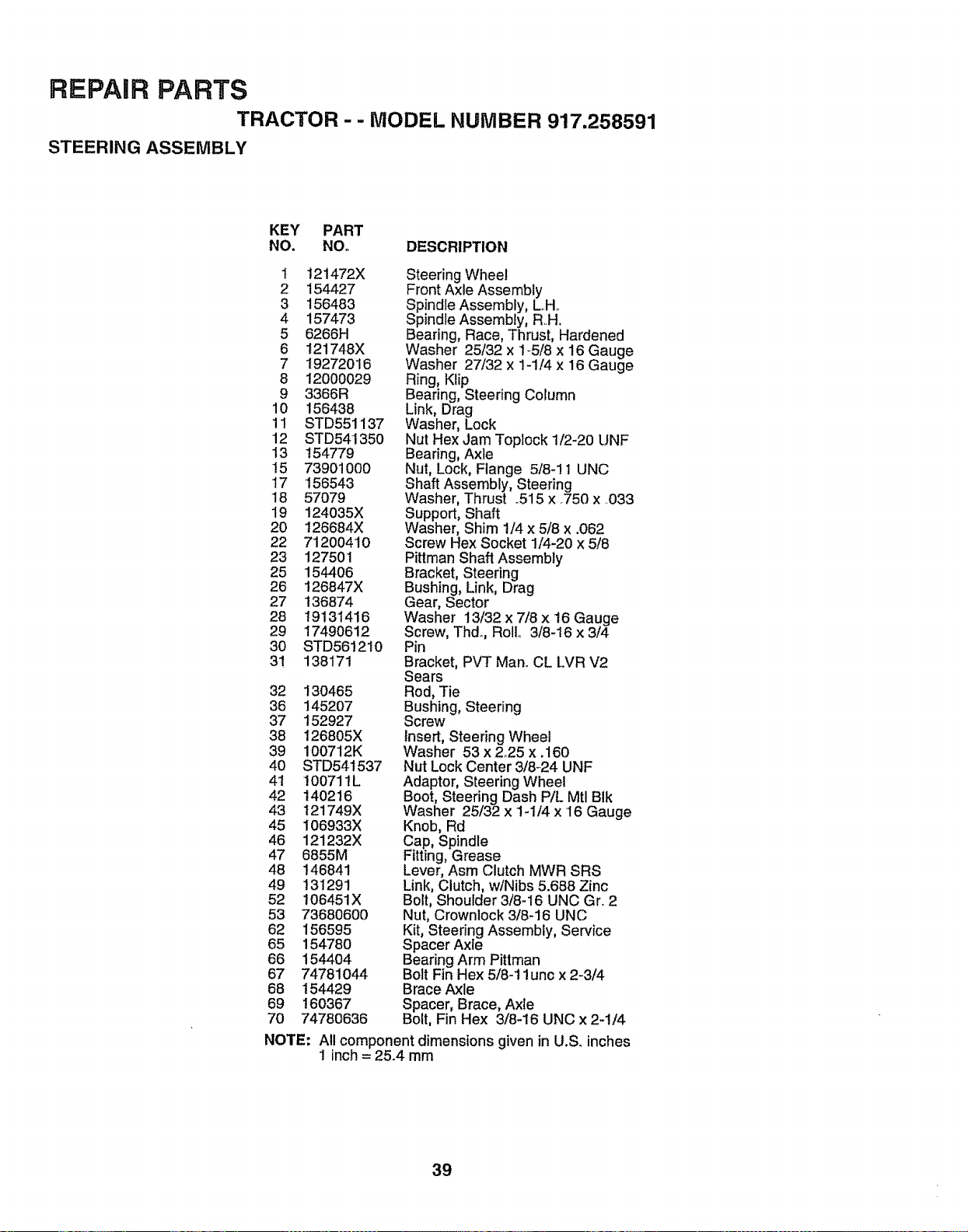
REPAIR PARTS
TRACTOR - - MODEL NUMBER 917.258591
STEERING ASSEMBLY
KEY PART
NO. NO. DESCRIPTION
1 t21472X
2 154427
3 156483
4 157473
5 6266H
6 121748X
7 19272016
8 12000029
9 3366R
10 156438
11 STD551137
12 STD541350
13 t54779
15 73901000
17 156543
18 57079
19 124035X
20 126684X
22 71200410
23 127501
25 154406
26 126847X
27 t36874
28 19131416
29 17490612
30 STD561210
31 138171
32 130465
36 145207
37 152927
38 126805X
39 i00712K
4O STD541537
41 100711L
42 14O216
43 t21749X
45 106933X
46 121232X
47 6855M
48 146841
49 131291
52 t0645iX
53 73680600
62 156595
65 154780
66 154404
67 74781044
68 154429
69 160367
70 74780636
Steering Wheel
Front Axle Assembly
Spindle Assembly, L,Ho
Spindle Assembly, RH.
Bearing, Race, Thrust, Hardened
Washer 25/32 x 1_5/8 x 16 Gauge
Washer 27/32 x 1-1/4 x 16 Gauge
Ring, Klip
Bearing, Steering Column
Link, Drag
Washer, Lock
Nut Hex Jam Toplock 1/2-20 UNF
Bearing, Axle
Nut, Lock, Flange 5/8-11 UNC
Shaft Assembly, Steering
Washer, Thrust .515 x .750 x 033
Support, Shaft
Washer, Shim 1/4 x 5/8 x .062
Screw Hex Socket 1/4-20 x 5/8
Pittman Shaft Assembly
Bracket, Steering
Bushing, Link, Drag
Gear, Sector
Washer 13/32 x 7/8 x 16 Gauge
Screw, Thd. Roll. 3/8-16 x 3/4
Pin
Bracket, PVT Man. CL LVR V2
Sears
Rod, Tie
Bushing, Steering
Screw
Insert, Steering Wheel
Washer 53 x 2°25 x .160
Nut Lock Center 3/8-24 UNF
Adaptor, Steering Wheel
Boot, Steering Dash P/L Mtl BIk
Washer 25/32 x t-1/4 x '16 Gauge
Knob, Rd
Cap, Spindle
Fitting, Grease
Lever, Asm Clutch MWR SRS
Link, Clutch, w/Nibs 5.688 Zinc
Bolt, Shoulder 3/8-16 UNC Gr. 2
Nut, Crownlock 3/8-16 UNC
Kit, Steering Assembly, Service
Spacer Axle
Bearing Arm Pittman
Bolt Fin Hex 5/8-11 unc x 2-3/4
Brace Axle
Spacer, Brace, Axle
Bolt, Fin Hex 3/8-16 UNC x 2-1/4
NOTE: All component dimensions given in U.So inches
1 inch= 25.4 mm
39
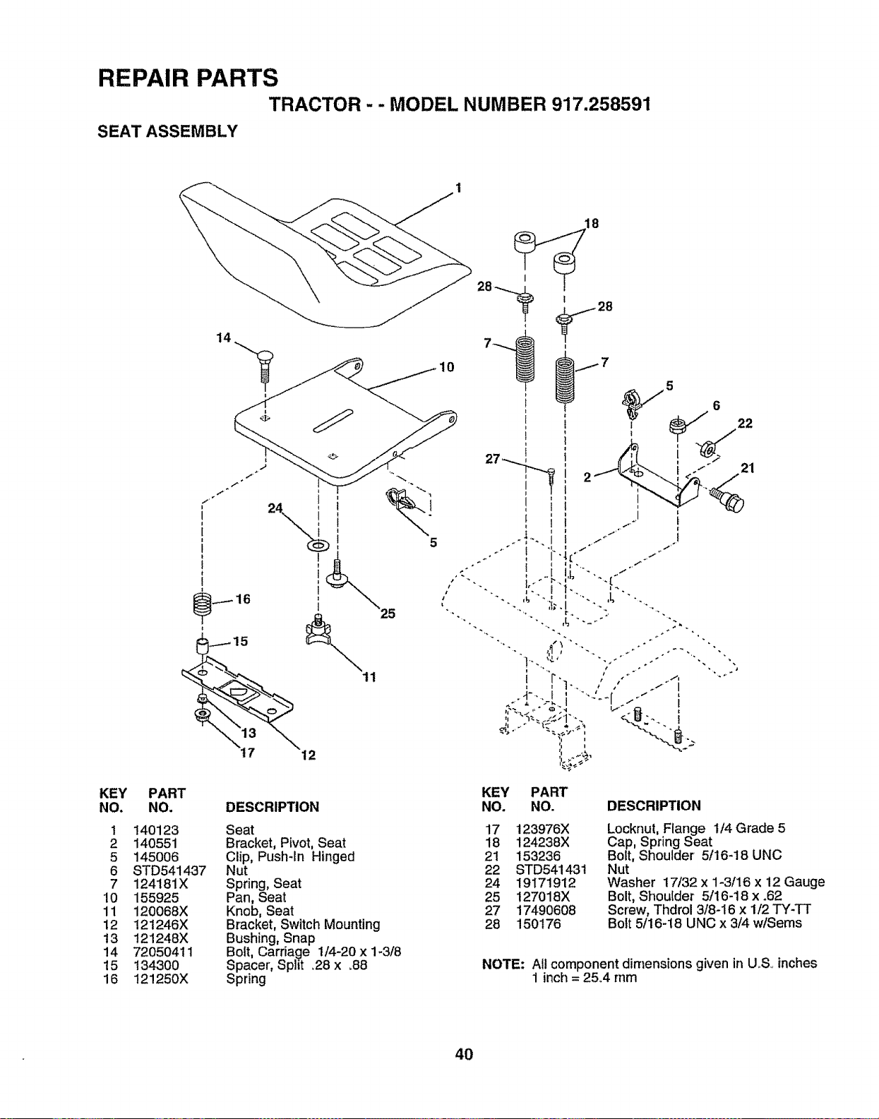
REPAIR PARTS
TRACTOR - - MODEL NUMBER 917.258591
SEAT ASSEMBLY
KEY PART
NO. NO.
1 140123
2 140551
5 145006
6 STD541437
7 124181X
10 155925
11 120068X
12 !21246X
13 121248X
14 72050411
!5 134300
16 12!250X
14
12
DESCRIPTION
Seat
Bracket, Pivot, Seat
Clip, Push-In Hinged
Nut
Spring, Seat
Pan, Seat
Knob, Seat
Bracket, Switch Mounting
Bushing, Snap
Bolt, Carriage i/4-20 x 1-3/8
Spacer, Split .28 x 38
Spring
10
5
o 21
KEY PART
NO. NO. DESCRIPTION
17 123976X
18 124238X
21 153236
22 STD541431
24 19171912
25 !27018X
27 17490608
28 150176
Locknut, Flange 1/4 Grade 5
Cap, Spring Seat
Bolt, Shoulder 5/16-18 UNC
Nut
Washer 17/32 x 1-3/16 x 12 Gauge
Bolt, Shoulder 5/16-t8 x .62
Screw, Thdrol 3/8-16 x 1/2 TY-TT
Bolt 5/16-18 UNC x 3/4 w/Seres
NOTE: All component dimensions given in U,Soinches
1 inch = 25.4 mm
4O
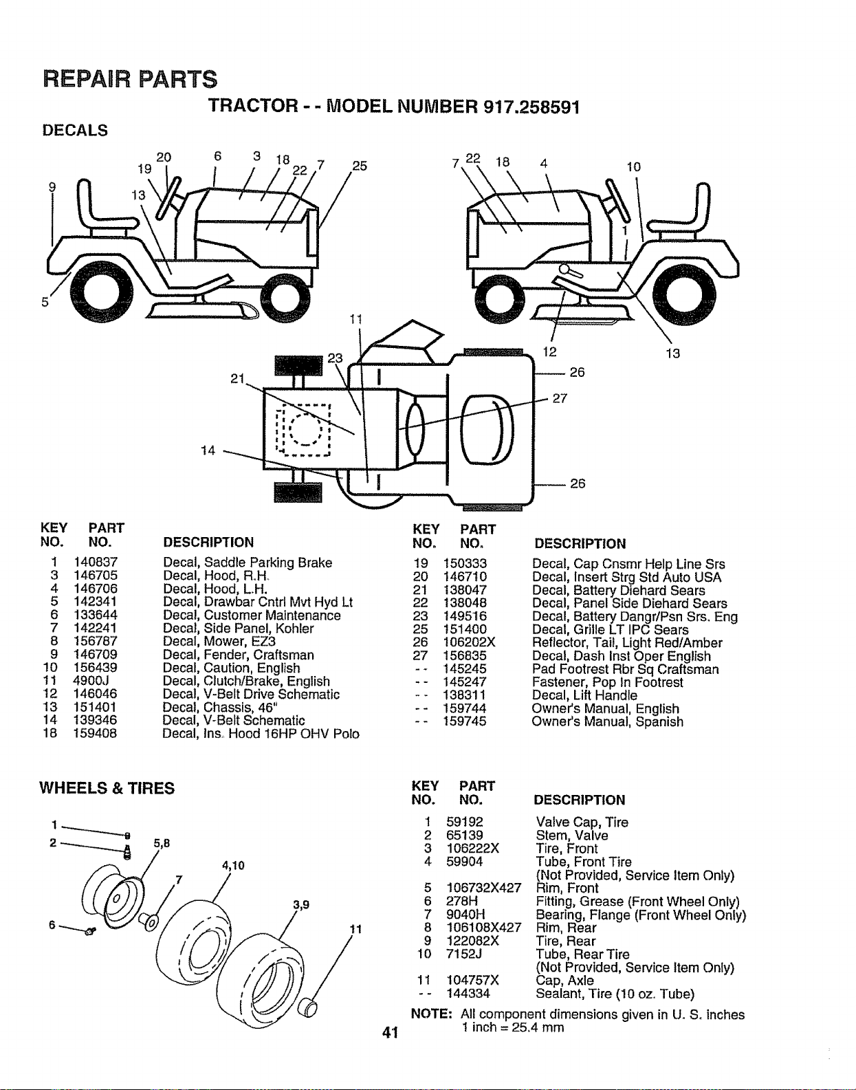
REPAIR PARTS
TRACTOR -- MODEL NUMBER 917.258591
20 6 3 18
19 7 25 7,
DECALS
21
11
18 4
12
26
27
10
13
14
KEY PART
NO. NO.
1 140837
3 146705
4 146706
5 142341
6 133644
7 142241
8 156787
9 146709
!0 156439
11 4900J
12 146046
13 151401
14 139346
18 159408
KEY PART
DESCRIPTION NO. NO.
Decal, Saddle Parking Brake 19 150333
Decal, Hood, RoH_ 20 146710
Decal, Hood, LH. 21 138047
Decal, Drawbar Cntrl Mvt Hyd Lt 22 138048
Decal, Customer Maintenance 23 149516
Decal, Side Panel, Kohler 25 151400
Decal, Mower, EZ3 26 I06202X
Decal, Fender, Craftsman 27 156835
Decal, Caution, English - - 145245
Decal, Clutch/Brake, English - - 145247
Decal, V-Belt Drive Schematic - - 138311
Decal, Chassis, 46" - - 159744
Decal, V-Belt Schematic - - 159745
Decal, Ins, Hood 16HP OHV Polo
DESCRIPTION
Decal, Cap Cnsmr Help Line Srs
Decal, Insert Strg Std Auto USA
Decal, Battery Diehard Sears
Decal, Panel Side Diehard Sears
Decal, Batter,] Dangr/Psn Srs. Eng
Decal, Grille LT IPC Sears
Reflector, Tail, Light Red/Amber
Decal, Dash inst Oper English
Pad Footrest Rbr Sq Craftsman
Fastener, Pop In Footrest
Decal, Lift Handle
Owner's Manual, English
Owner's Manual, Spanish
WHEELS & TIRES
5,8
4,10
7
11
4'i
KEY PART
NO. NO. DESCRIPTION
1 59192
2 65139
3 106222X
4 59904
5 106732X427
6 278H
7 9040H
8 106108X427
9 122082X
10 7152J
11 104757X
-- 144334
NOTE:
Valve Cap, Tire
Stem, Valve
Tire, Front
Tube, Front Tire
(Not Provided, Service Item Only)
Rim, Front
Fitting, Grease (Front Wheel Only)
Bearing, Flange (Front Wheel Only)
Rim, Rear
Tire, Rear
Tube, Rear Tire
(Not Provided, Service item Only)
Cap, Axle
Sealant, Tire (10 ozo Tube)
Al! component dimensions given in U. So inches
I inch = 25.4 mm

REPAIR PARTS
TRACTOR- - MODEL NUMBER 917.258591
ENGINE
32 31
40
39
I
34
37
80,
4
29
\
"" ,++" I Tt'_ +, _1 +
"+-=. ++'.<, ..+_++,l.,.-1,4,,+_-'
\%......"
23
OPTIONAL EQUIPMENT
Spark Arrester
42
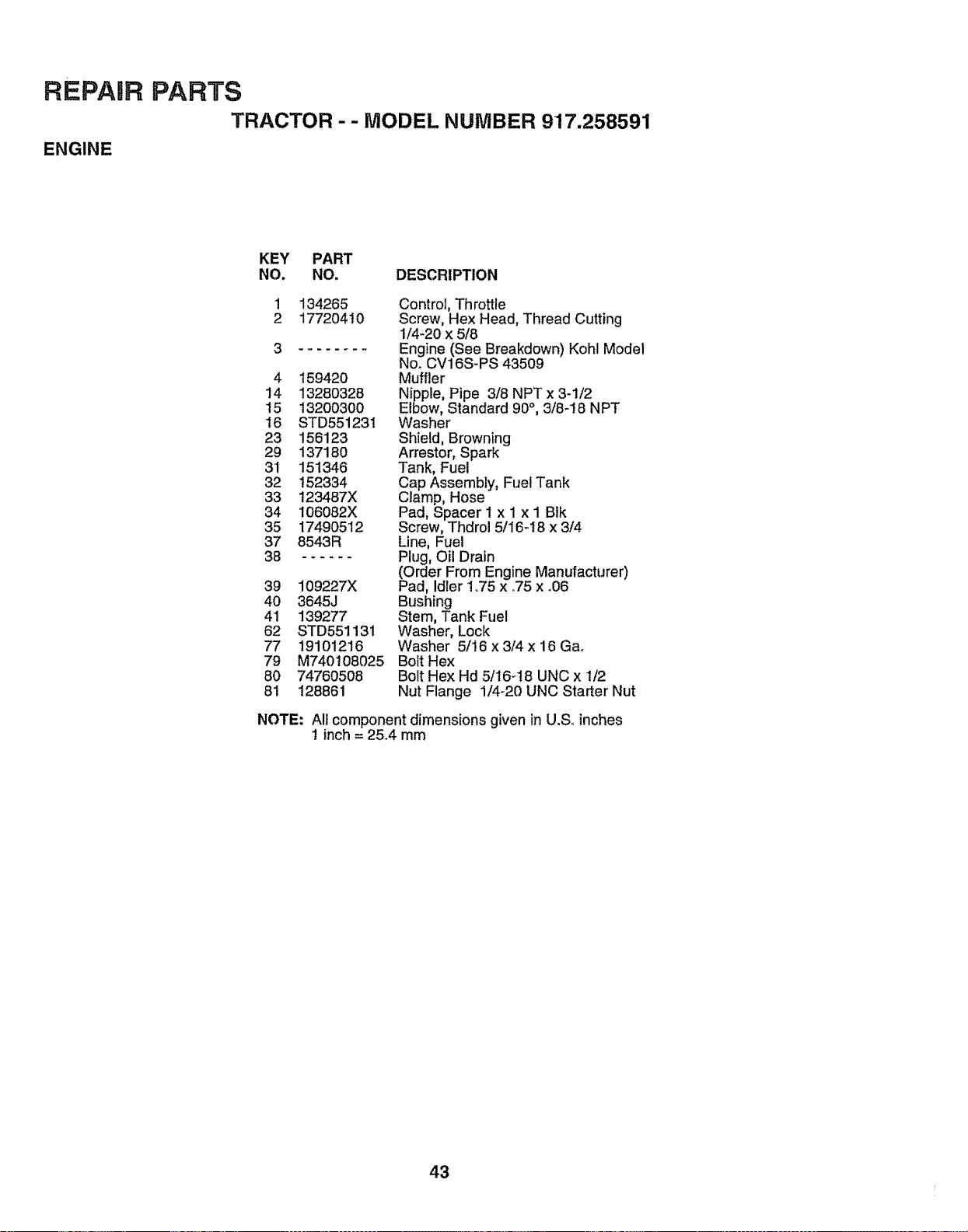
REPARR
ENGINE
PARTS
TRACTOR - - MODEL NUMBER 917.258591
KEY PART
NO. NO. DESCRIPTION
1 134265
2 17720410
3
4 159420
14 13280328
15 13200300
16 STD551231
23 156123
29 137180
3'1 151346
32 152334
33 123487X
34 106082X
35 17490512
37 8543R
38 ......
39 109227X
40 3645J
41 139277
62 STD551131
77 19101216
79 M740108025
80 74760508
81 128861
Control, Throttle
Screw, Hex Head, Thread Cutting
1/4_20 x 5/8
Engine (See Breakdown) Kohl Model
Nor CV16S-PS 43509
Muffler
Nipple, Pipe 3/8 NPT x 3-!/2
Elbow, Standard 90°, 3/8-18 NPT
Washer
Shield, Browning
Arrestor, Spark
Tank, Fuel
Cap Assembly, Fuel Tank
Clamp, Hose
Pad, Spacer 1 x 1 x I Blk
Screw, Thdrol 5/I6-t8 x 3/4
Line, Fuel
Plug, Oil Drain
(Order From Engine Manufacturer)
Pad, Idler 1,75 x °75 x °06
Bushing
Stem, Tank Fuel
Washer, Lock
Washer 5/16 x 3/4 x 16 Gao
Bolt Hex
Bolt Hex Hd 5/16_18 UNC x 1/2
Nut Flange 1/4-20 UNC Starter Nut
NOTE: All component dimensions given in U.S, inches
1 inch= 25.4 mm
43
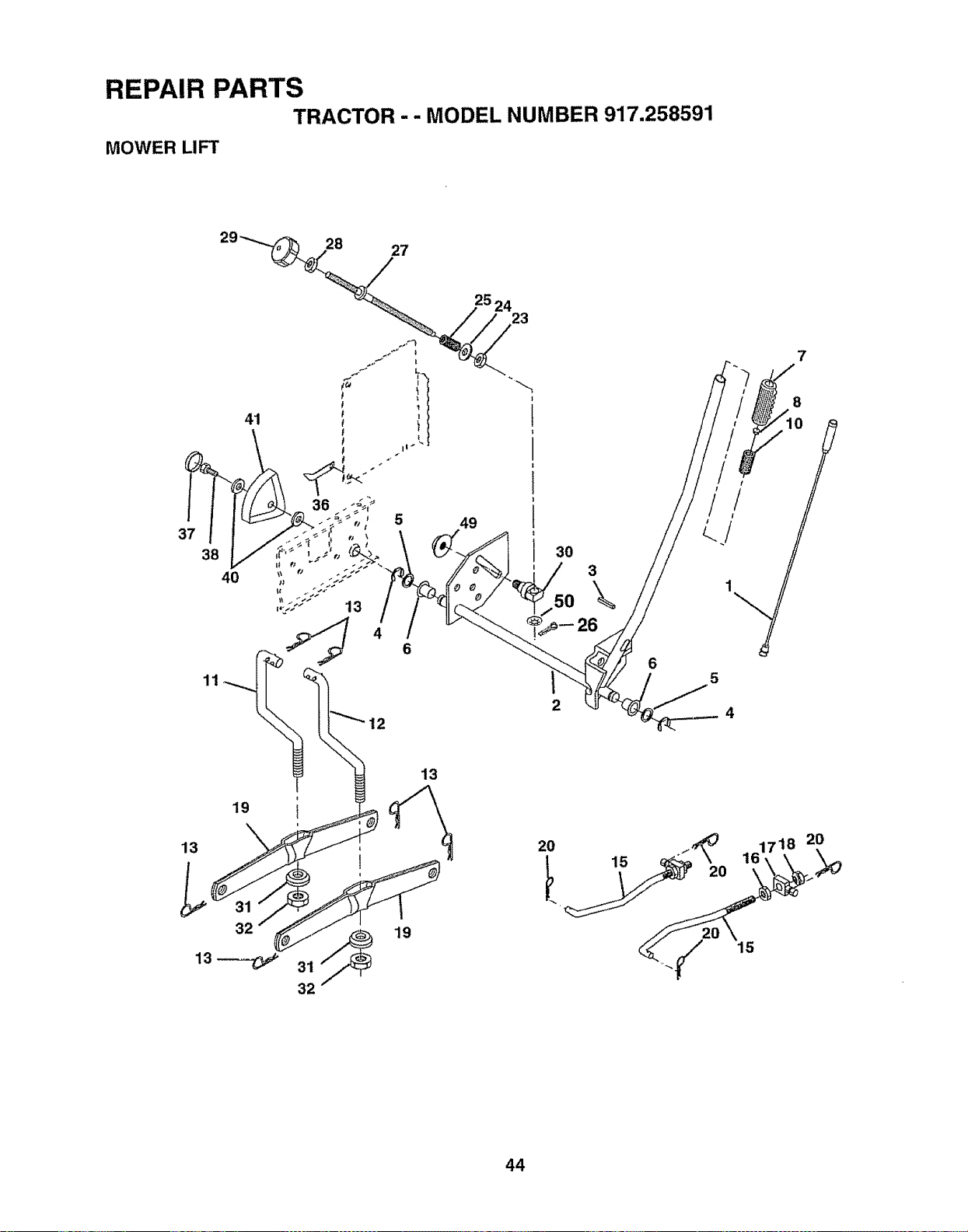
REPAIR PARTS
TRACTOR -- MODEL NUMBER 917.258591
MOWER LIFT
37
41
38
40
4
6
11
25 24
23
30
50
2
3
\
26
6
4
19
13
32
19
13
20 15 _'_ 16171_ 2_,_
44
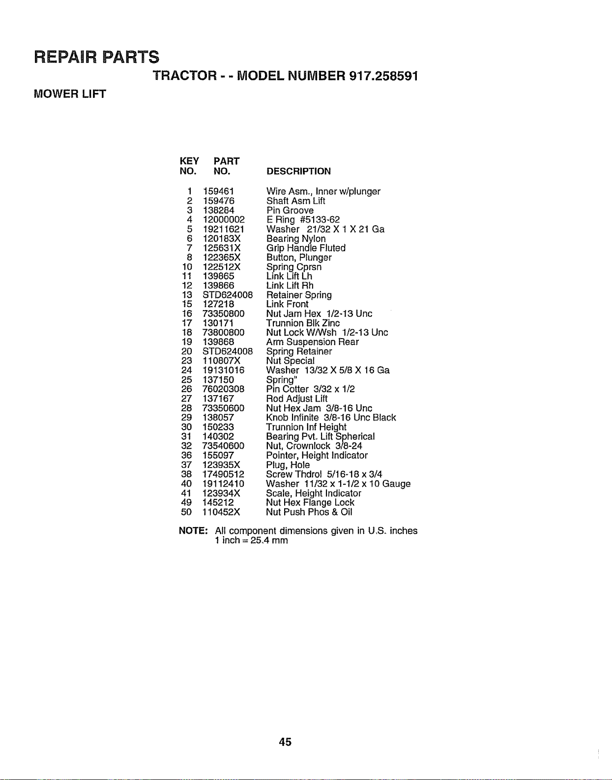
REPAIR PARTS
TRACTOR -- MODEL NUMBER 917.258591
MOWER LIFT
KEY PART
NO. NO. DESCRIPTION
1 159461 WireAsmo, Innerw/plunger
2 159476 Shaft Asm Lift
3 138284 Pin Groove
4 12000002 E Ring #5133-62
5 19211621 Washer 21/32 X 1 X 21 Ga
6 120183X Bearing Nylon •
7 125631X Grip Handte Fluted
8 122365X Button, Plunger
10 122512X Spring Cprsn
11 139865 Link Lift Lh
12 139866 Link Lift Rh
t3 STD624008 Retainer Spring
15 127218 Link Front
16 73350800 Nut Jam Hex t/2-13 Unc
I7 !30171 Trunnion BIk Zinc
18 73800800 Nut Lock WiWsh 1/2-13 Unc
19 139868 Arm Suspension Rear
20 STD624008 Spring Retainer
23 110807X Nut Special
24 19131016 Washer 13!32X518X 16 Ga
25 137150 Spring"
26 76020308 Pin Cotter 3/32 x 1/2
27 137167 Rod Adjust Lift
28 73350600 Nut Hex Jam 3/8-16 Unc
29 138057 Knob Infinite 3/8-16 Unc Black
30 150233 Trunnion Inf Height
31 140302 Bearing Pvto LEftSpherical
32 73540600 Nut, Crownlock 3/8-24
36 155097 Pointer, Height Indicator
37 t23935X Plug, Hole
38 17490512 Screw Thdrol 5/16-18 x 3/4
40 19112410 Washer 11/32 x 1-t/2 x 10 Gauge
41 123934X Scale, Height Indicator
49 145212 Nut Hex Flange Lock
50 110452X Nut Push Phos & Oil
NOTE: All component dimensions given in U.S. inches
1 inch = 25°4 mm
45
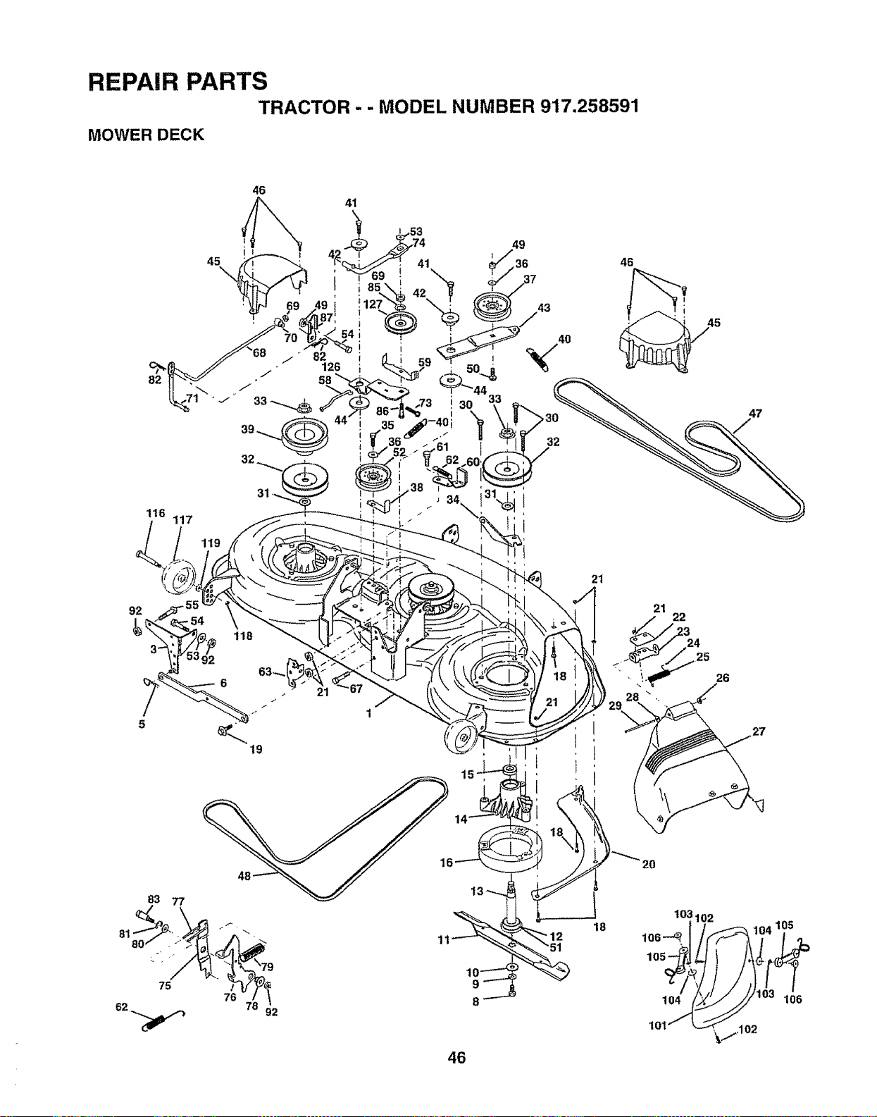
REPAIR PARTS
TRACTOR - - MODEL NUMBER 917.258591
MOWER DECK
46
41
116
117
15
21
21
22
26
81
83 77
75
f,
10
8
46
+12
18
104
10I
105
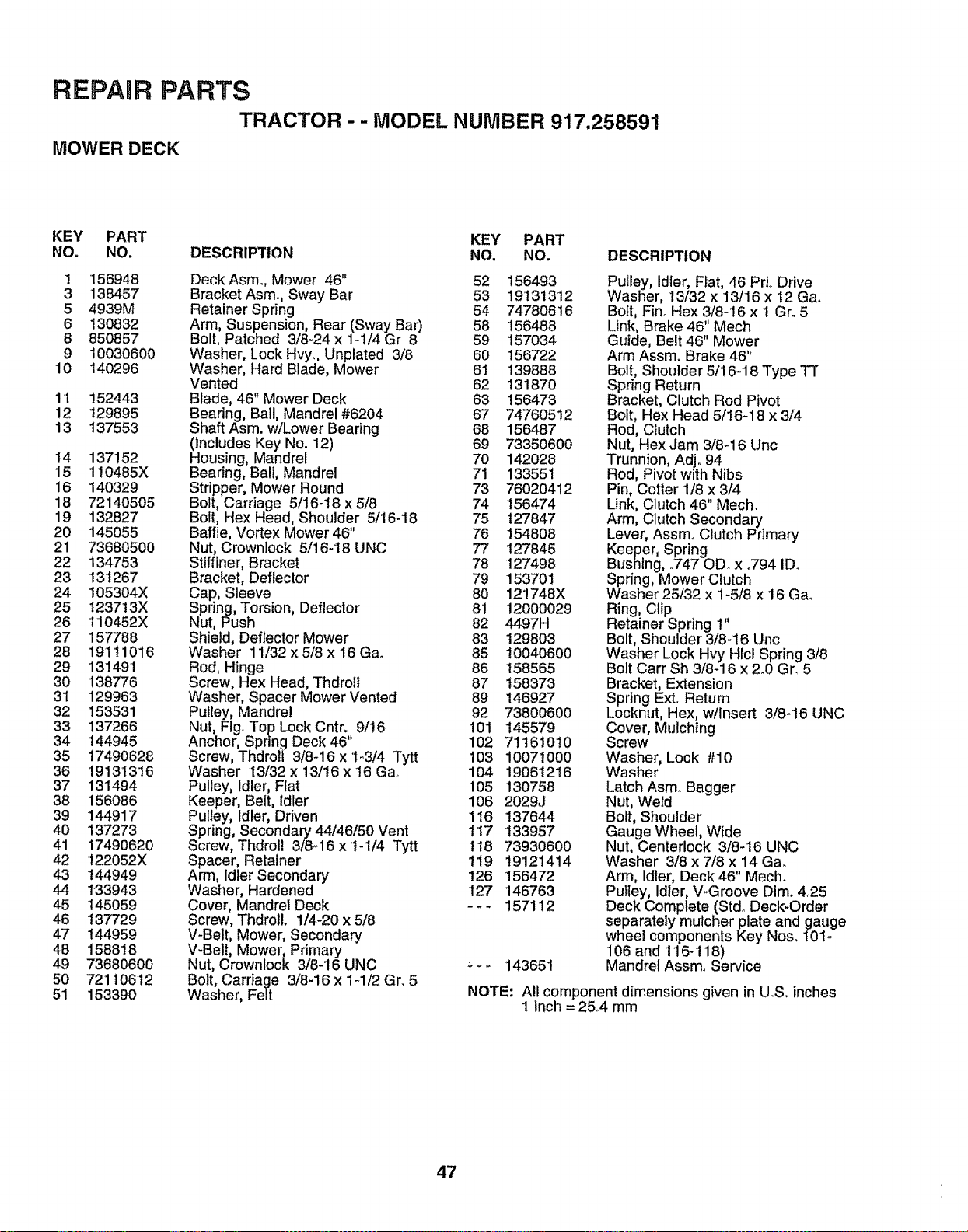
REPAIR PARTS
TRACTOR - - MODEL NUMBER 917.25859!
MOWER DECK
KEY PART KEY PART
NO. NO. DESCRIPTION NO, NO. DESCRIPTION
1 156948
3 138457
5 4939M
6 130832
8 850857
9 10030600
10 140296
11 152443
12 129895
13 137553
14 137152
15 110485X
16 140329
18 72140505
19 132827
20 145055
21 73680500
22 134753
23 131267
24 105304X
25 1237t3X
26 110452X
27 157788
28 19111016
29 131491
30 138776
31 129963
32 153531
33 137266
34 144945
35 17490628
36 19131316
37 131494
38 156086
39 144917
40 137273
41 17490620
42 122052X
43 144949
44 1"33943
45 145059
46 137729
47 144959
48 158818
49 73680600
50 721106"t2
51 153390
Deck Asm., Mower 46" 52 156493
BracketAsm, Sway Bar 53 19131312
Retainer Spring 54 74780616
Arm, Suspension, Rear (Sway Bar) 58 156488
Bolt, Patched 3/8-24 x 1-1/4 Gr. 8 59 157034
Washer, Lock Hvy., Unplated 3/8 60 156722
Washer, Hard Blade, Mower 61 139888
Vented 62 131870
Blade, 46" Mower Deck 63 156473
Bearing, Bail, Mandrel #6204 67 74760512
Shaft Asm. w/Lower Bearing 68 156487
(Includes Key No. 12) 69 73350600
Housing, Mandrel 70 142028
Bearing, Ball, Mandrel 71 133551
Stripper, Mower Round 73 76020412
Bolt, Carriage 5/16-18 x 5/8 74 156474
Bolt, Hex Head, Shoulder 5/16-18 75 127847
Baffle, Vortex Mower 46" 76 154808
Nut, Crownlock 5/16-18 UNC 77 127845
Stiffiner, Bracket 78 127498
Bracket, Deflector 79 153701
Cap, Sleeve 80 121748X
Spring, Torsion, Deflector 81 12000029
Nut, Push 82 4497H
Shield, Deflector Mower 83 129803
Washer 11/32 x 5/8 x 16 Ga. 85 10040600
Rod, Hinge 86 158565
Screw, Hex Head, Thdroil 87 t58373
Washer, Spacer Mower Vented 89 146927
Puitey, Mandrel 92 73800600
Nut, Fig. Top Lock Cntr. 9/!6 101 145579
Anchor, Spring Deck 46 102 71161010
Screw, Thdroll 3/8-i6 x 1-3/4 Tytt 103 10071000
Washer 13/32 x 13/16 x 16 Ga_ 104 19061216
Pulley, Idler, Flat 105 130758
Keeper, Belt, Idler 106 2029J
Pulley, Idler, Driven 116 137644
Spring, Secondary 44/46/50 Vent t 17 133957
Screw, Thdrol! 3/8-16 x 't-1/4 Tytt 118 73930600
Spacer, Retainer t19 19121414
Arm, Idler Secondary 126 156472
Washer, Hardened 127 146763
Cover, Mandrel Deck - - - 157112
Screw, ThdrolL 1/4-20 x 5/8
V-Belt, Mower, Secondary
V-Belt, Mower, Primary
Nut, Crownlock 3/8-16 UNC --- 143651
Bolt, Carriage 3/8-16 x 1-1/2 Gr. 5
Washer, Felt
Pulley, Idler, Fiat, 46 Prio Drive
Washer, 13/32 x 13/16 x 12 Ga.
Bolt, Fin_ Hex 3/8-16 x 1 Gro 5
Link, Brake 46" Mech
Guide, Belt 46" Mower
Arm Assm. Brake 46"
Bolt, Shoulder 5/16-18 Type TT
Spring Return
Bracket, Clutch Rod Pivot
Bolt, Hex Head 5/16-18 x 3/4
Rod, Clutch
Nut, Hex,Jam 3/8-16 Uric
Trunnion, Adjo 94
Rod, Pivot with Nibs
Pin, Cotter 1/8 x 3/4
Link, Clutch 46" Mech,
Arm, Clutch Secondary
Lever, Assm. Clutch Primary
Keeper, Spring
Bushing, ,.747 OD. x .794 ID.
Spring, Mower Clutch
Washer 25/32 x 1-5/8 x 16 Ga_
Ring, Clip
Retainer Spring 1"
Bolt, Shoulder 3/8-16 Unc
Washer Lock Hvy Hlci Spring 3/8
Bolt Cart Sh 3/8-16 x 2.0 Gr, 5
Bracket, Extension
Spring Ext. Return
Locknut, Hex, w/Insert 3/8-16 UNC
Cover, Mulching
Screw
Washer, Lock #10
Washer
Latch Asm° Bagger
Nut, We_d
Bolt, Shoulder
Gauge Wheel, Wide
Nut, Centerlock 3/8-'16 UNC
Washer 3/8 x 7/8 x 14 Ga.
Arm, idler, Deck 46" Mech.
Pulley, Idler, V-Groove Dim. 4°25
Deck Complete (Stdo Deck-Order
separately mulcher plate and gauge
wheel components Key Nos. t01-
106 and 116-118)
Mandrel Assmo Service
NOTE: All component dimensions given in U.S. inches
1 inch = 25°4 mm
47

REPAIR PARTS
TRACTOR -- MODEL NUMBER 917.258591
HYDRO GEAR TRANSAXLE - MODEL NUMBER 310-0650
58
90 i3 52
\
91
19
34
26
23
18
7
27
28
59
14
4
5
3
35
113
48
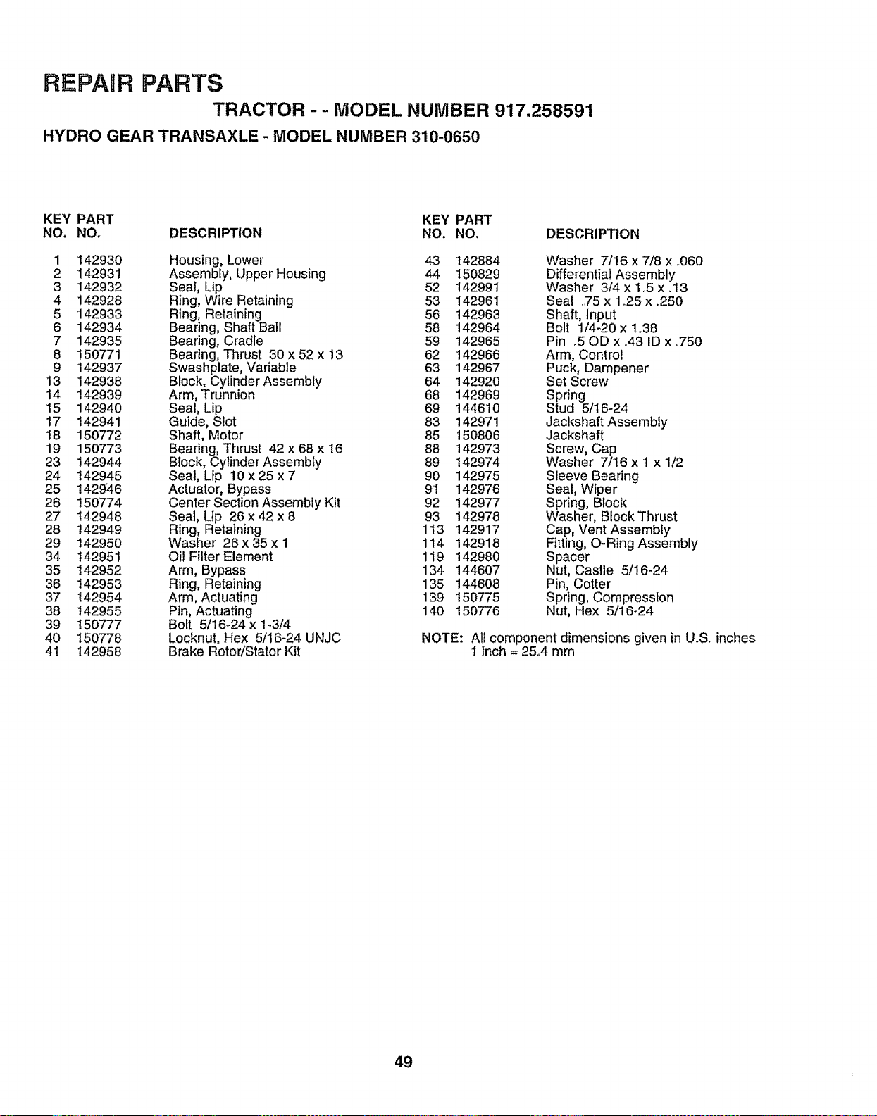
REPAIR PARTS
TRACTOR - - MODEL NUMBER 917.258591
HYDRO GEAR TRANSAXLE - MODEL NUMBER 310-0650
KEY PART KEY PART
NO. NO. DESCRIPTION NO. NO, DESCRIPTION
1 142930 Housing, Lower 43 142884 Washer 7/16 x 7/8 x 060
2 142931 Assembly, Upper Housing 44 150829 Differential Assembly
3 142932 Seal, Lip 52 142991 Washer 3/4 x 1o5 x.13
4 142928 Ring, Wire Retaining 53 142961 Seal ,.75x 1.25 x _250
5 142933 Ring, Retaining 56 142963 Shaft, Input
6 142934 Bearing, Shaft Ball 58 142964 Bolt 1/4-20 x 1.38
7 142935 Bearing, Cradle 59 142965 Pin .50D x .,43ID x ,750
8 150771 Bearing, Thrust 30 x 52 x 13 62 142966 Arm, Control
9 142937 Swashplate, Variable 63 142967 Puck, Dampener
13 142938 Block, Cylinder Assembly 64 142920 Set Screw
14 142939 Arm, Trunnion 68 142969 Spring
15 142940 Seal, Lip 69 144610 Stud 5/t6-24
17 142941 Guide, Slot 83 142971 JackshaftAssembly
18 150772 Shaft, Motor 85 150806 Jackshaft
19 150773 Bearing, Thrust 42 x 68 x 16 88 142973 Screw, Cap
23 142944 Block, Cylinder Assembly 89 142974 Washer 7/16 x 1 x 1/2
24 142945 Seal, Lip 10 x 25 x 7 90 142975 Sleeve Bearing
25 t429_,6 Actuator, Bypass 91 142976 Seal, Wiper
26 150774 Center Section Assembly Kit 92 142977 Sprang, Block
27 142948 Seal, Lip 26 x 42 x 8 93 142978 Washer, BIockThrust
28 142949 Ring, Retaining 113 142917 Cap, Vent Assembly
29 142950 Washer 26 x 35 x I 114 142918 Fitting, O-Ring Assembly
34 142951 Oil Filter Element 119 142980 Spacer
35 142952 Arm, Bypass 134 144607 Nut, Castle 5/16-24
36 142953 Ring, Retaining 135 144608 Pin, Cotter
37 142954 Arm, Actuating 139 150775 Spring, Compression
38 142955 Pin, Actuating 140 150776 Nut, Hex 5/16-24
39 t50777 Bolt 5/16-24 x 1-3/4
40 150778 Locknut, Hex 5/16-24 UNJC NOTE: All component dimensions given in U.So inches
41 142958 Brake RotoriStator Kit 1 inch = 25..4mm
49

REPAIR PARTS
TRACTOR -- MODEL NUMBER 917.258591
KOHLER ENGINE - MODEL NUMBER CV16S, TYPE NUMBER PS-43509
.................. II I'1 ..................................... m
CYLINDER HEAD, VALVE AND BREATHER !
......... nm_;.......
1
23
22
....................... II i,iiiii iii,
CRANKCASE !
t_8
..................... i,iii
19
_4
.... III II III
50

REPAIR PARTS
TRACTOR - - MODEL NUMBER 917.258590
KOHLER ENGINE - MODEL NUMBER CV16S, TYPE NUMBER PS-43509
CYLINDER HEAD/VALVEJBREATHER
CRANKCASE
KEY PART KEY PART
NO. NOo DESCRIPTION NO. NO. DESCRIPTION
1
2
3
4
5
12-351-02
12-755-63
12-41 I_01
12-041 -t 0
12_0t7-01
12-017-02
12-016-01
12-016-02
X-75-23
12-318-19
25-186-01
12-599-03
M-0640034
12-089-01
12-173-01
12-755-03
12_468-05
12-112-13
12-086-15
X-426-9
! 2-326-03
M-0645020
12-096-07
M-0545010
12-018-01
12-402-02
Lifter, valve (2)
Kit, cylinder head (Includes 3-17)
Rod, push (2)
Gasket, cylinder head
Valve, intake (Std)
Valve, intake (25)
Valve, exhaust (Std.)
Valve, exhaust (.25)
Plug, allen hd. pipe 1/8
Cylinder Head
Arm, rocker (2)
Pivot, rocker arm (2)
Screw, hex..flange M6xt..0x34 (2)
Spring, valve (2)
Cap, valve spring (2)
Kit, retainer (2)
Washer, plain 13/32
Spacer, head bolt exhaust port
Screw, hex. flange M10xt.5x81 (5)
Clamp, hose (2)
Hose, breather
Screw, hex. flange M6xl.0x20 (5)
Cover, valve w/nipple
Screw, hex. flange M5x0o8xl0
Retainer, breather reed
Reed, breather
7
8
9
10
11
12
13
14
15
16
17
18
19
2O
2!
22
23
24
1 12-032_03
2 Block, cylinder
3 12-445-02
4 M_0839025
5 12-380-17
6 12-755-49
7 12-089-18
8 12-422_08
12-422-09
12-422-10
12-422-11
12-422q 2
12-422-13
t2-422-07
9 t2-144-19
10 I2-874_07
12-874-08
12-874-09
11 12-018-02
12 12-108-07
12-108-08
12-108-09
13 12-067-05
12-067-06
14 12-380-01
15 12-043-05
16 M-0631005
17 12-144-02
18 52-139-09
19 12-755-64
20 12-144-24
21 X-25-t02
22 12-032-01
23 SM-0631015
24 12-154-05
Seal, crankshaft
(Use Short Block 12 522 18)
Strap, lifting
Screw, hex, flange M8xlo25x25
Dowel, locating (4)
Kit, camshaft (Includes 7-8)
Spring, actuating
Shim, camshaft - blue
Shim, camshaft (A,R,) red
Shim, camshaft (A,Ro) yellow
Shim, camshaft IA R / green
Shim, camshaft i i gray
Shim, camshaft (AR..) black
Shim, camshaft (A.R.) white
Shaft, balance
Piston w/Ring Set (St&)
(Includes 11-12)
Piston w/Ring Set (.25)
Piston w!Ring Set (.50)
Retainer, piston pin (2)
Ring Set (Stdo)
Ring Set (25)
Ring Set (.50)
Connecting Rod (Std.)
Connecting Rod (.25)
Pin, governor regulating
Gear, governor assembly
Washer, plain 6ram
Shaft, governor gear
Plug, cup
Kit, gow cross shaft w/clip
(Includes 20,24)
Shaft, governor cross
washer, plain 1/4
Seal, governor cross shaft
Washer, plain 6ram
Clip, hitch pin
5'I
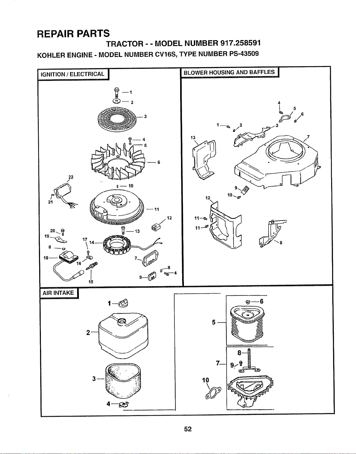
REPAIR PARTS
TRACTOR - - MODEL NUMBER 917.258591
KOHLER ENGINE - MODEL NUMBER CV16S, TYPE NUMBER PS-43509
I'L'J,J IIIIll,,l"'' ,, '" .......
IGNITION/ELECTRICAL I
7_
10
52
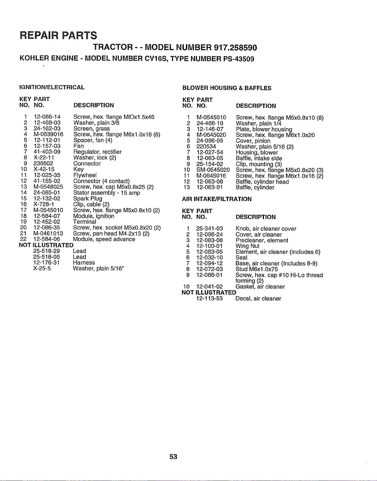
REPAIR PARTS
TRACTOR- - MODEL NUMBER 917,258590
KOHLER ENGINE - MODEL NUMBER CV16S, TYPE NUMBER PS-43509
IGNITION/ELECTRICAL
BLOWER HOUSING & BAFFLES
KEY PART KEY PART
NO. NO. DESCRIPTION NO. NOo DESCRIPTION
Screw, hex. flange MIOx1..5x46
Washer, plain 3/8
Screen, grass
Screw, hexo flange M6xlo0x16 (6)
Spacer, fan (4)
Fan
Regulator, rectifier
Washer, lock (2)
Connector
Key
Flywheel
Connector (4 contact)
Screw, hex_ cap M5x0.Sx25 (2)
Stator assembly - 15 amp
Spark Plug
Clip, cable (2)
Screw, hex, flange M5x0_Sxl0 (2)
Module, ignition
Terminal
Screw, hex. socket M5x0,8x20 (2)
Screw, pan head M4.2x13 (2)
Module, speed advance
1 12-086-14
2 12-468-03
3 24-162-03
4 M-0639016
5 12-112-01
6 12-157-03
7 41-403-09
8 X_22-11
9 236602
10 X-42-15
11 !2-025-35
12 41-155-02
13 M-0548025
14 24-085-01
15 12-132-02
16 X-728-1
17 M-0545010
18 12-584-07
19 12-452-02
20 12-086-35
21 M-0461013
22 12_584-06
NOT ILLUSTRATED
25-518-29 Lead
25-518-05 Lead
12-176-31 Harness
X-25-5 Washer, plain 5/16"
1 M-0545010
2 24-468-10
3 12-t46-07
4 M-0645020
5 24-096-05
6 220534
7 12-027-54
8 12-063-05
9 25_154-02
t0 SM-0545020
I1 M-0645016
12 12-063-08
13 12-063_01
Screw, hex. flange M5x0.Sxl0 (8)
Washer, plain 1/4
Plate, blower housing
Screw, hexo flange M6xl.0x20
Cover, pinion
Washer, plain 5/16 (2)
Housing, blower
Baffle, intake side
Clip, mounting (3)
Screw, hex. flange M5x0.8x20 (3)
Screw, hex. flange M6xl _0x16 (2)
Baffle, cylinder head
Baffle, cylinder
AIR INTAKE/FILTRATION
KEY PART
NO. NO.
DESCRIPTION
1 25-34!-03
2 I2-096-24
3 12-083-08
4 12-100-01
5 12-083-05
6 12-032-10
7 12-094-12
8 12-072-03
9 12-086-01
t0 12-041-02
NOT
Knob, air cleaner cover
Cover, air cleaner
Precleaner, element
Wing Nut
Element, air cleaner (Includes 6)
Seal
Base, air cleaner (Includes 8-9)
Stud M6xl o0x75
Screw, hex. cap #10 Hi-Lo thread
forming (2)
Gasket, air cleaner
ILLUS3"RATED
12-113-53 Decal, air cleaner
53
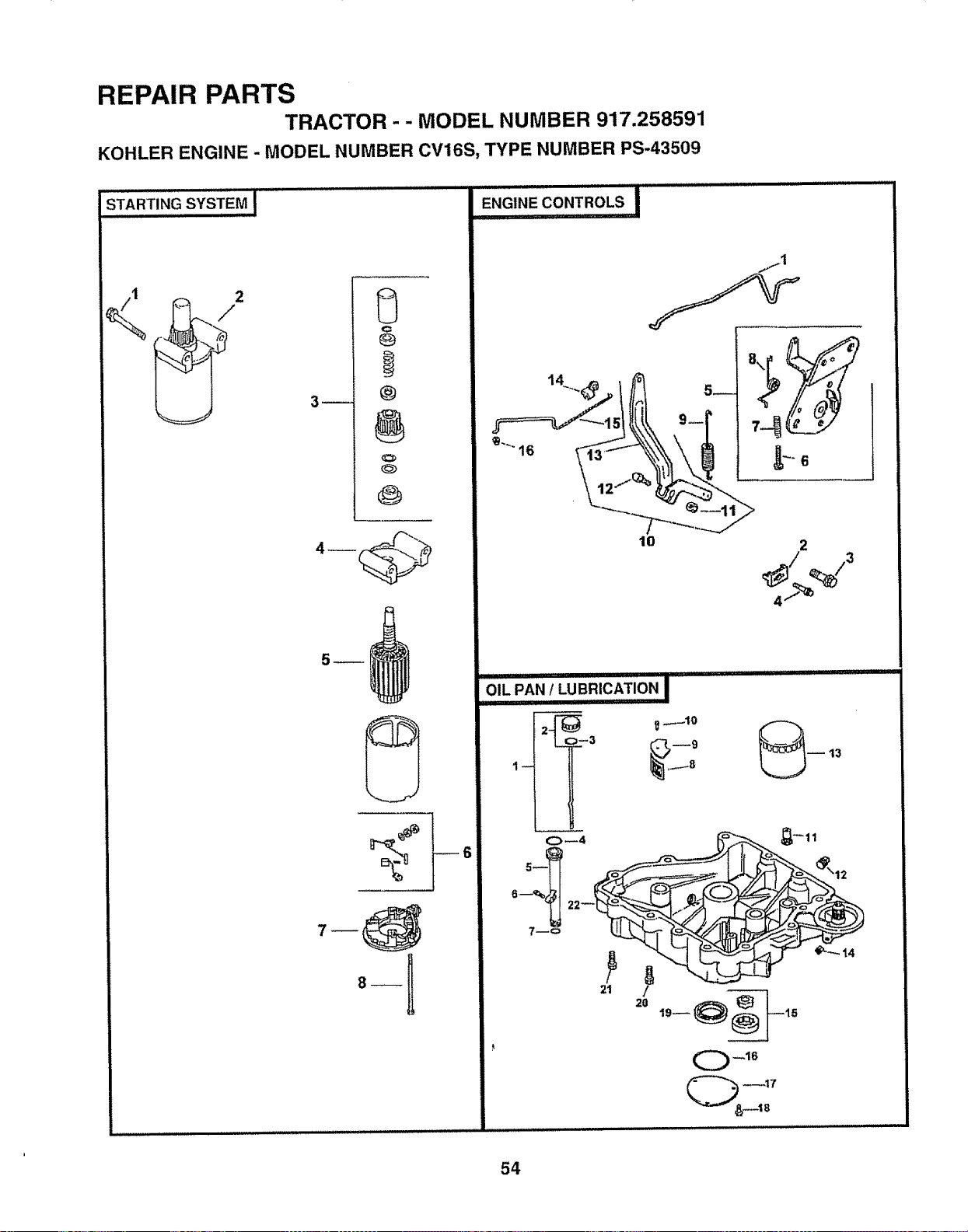
REPAIR PARTS
TRACTOR - - MODEL NUMBER 917,258591
KOHLER ENGINE - MODEL NUMBER CV16S, TYPE NUMBER PS-43509
/
0
C
3-- @
@
lO 2
4.....% '="
.................................... III iiiii II I1'1
OIL PAN / LUBRICATION I
/
2O
54
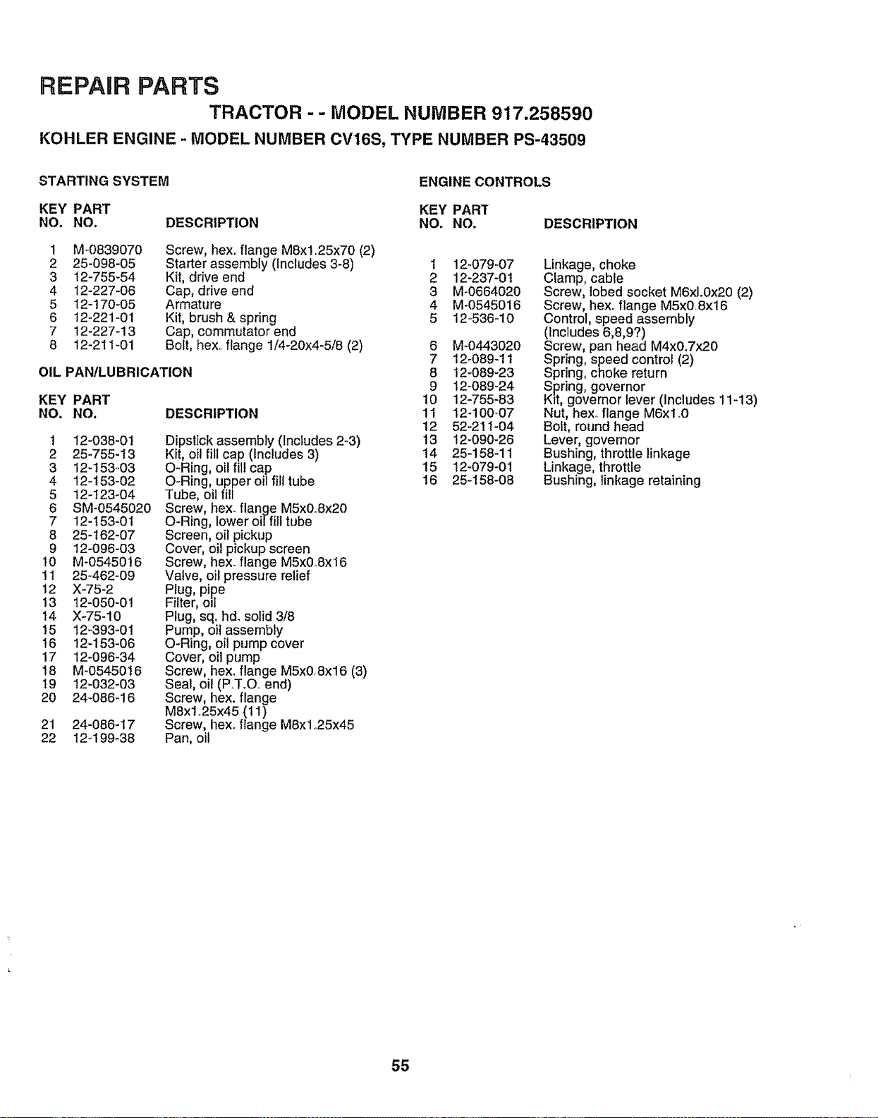
REPAIR PARTS
TRACTOR -- MODEL NUMBER 917.258590
KOHLER ENGINE - MODEL NUMBER CV16S, TYPE NUMBER PS-43509
STARTING SYSTEM ENGINE CONTROLS
KEY PART KEY PART
NO. NO, DESCRIPTION NOo NO. DESCRIPTION
1
2
3
4
5
6
7
8
M-0839070
25-098-05
t2-755-54
12-227-06
12-170-05
12-221-01
12-227-13
12-211-01
Screw, hexoflange M8x1.25x70 (2)
Starter assembly (Includes 3-8)
Kit, drive end
Cap, drive end
Armature
Kit, brush & spring
Cap, commutator end
Bolt, hex.. flange 1/4-20x4-5/8 (2)
OIL PANtLUBRICATION
KEY PART
NO. NO. DESCRIPTION
1
2
3
4
5
6
7
8
9
10
11
12
13
14
15
16
17
18
19
20
21
22
12-038-0t
25-755-13
12-153-03
12-t53-02
12-123-04
SM-0545020
12-I53-01
25-162-07
12-096-03
M-0545016
25-462-09
X-75-2
12-050-01
X-75-10
12-393-01
12-153-06
12-096-34
M-0545016
12-032-03
24-086-16
24-086-17
124 99-38
Dipstick assembly (Includes 2-3)
Kit, oil fill cap (Includes 3)
O-Ring, oil fill cap
O-Ring, upper oil fill tube
Tube, oil fill
Screw, hex. flange M5x0.Sx20
O-Ring, lower oil fill tube
Screen, oil pickup
Cover, oil pickup screen
Screw, hex. flange M5x0.8x16
Valve, oil pressure relief
Plug, pipe
Filter, ol!
Plug, sq. h& solid 3/8
Pump, oil assembly
O-Ring, oil pump cover
Cover, oil pump
Screw, hexoflange M5x0.Sx16 (3)
Seal, oil (P..T.Q. end)
Screw, hex. flange
MSxl. 25x45 (11)
Screw, hexoflange M8x1.25x45
Pan, oil
1 12_079_07
2 12-237-01
3 M-0664020
4 M-0545016
5 12_536-10
6 M-0443020
7 12-089-11
8 12-089-23
9 12-089-24
10 12-755-83
11 12-100_07
12 52-211-04
13 12-090-26
14 25-158-11
15 12-079-01
16 25-158-08
Linkage, choke
Clamp, cable
Screw, lobed socket M6xl.0x20 (2)
Screw, hexo flange MSx0..Sx16
Control, speed assembly
(includes 6,8,9?)
Screw, pan head M4x&7x20
Spring, speed control (2)
Spring, choke return
Spring, governor
K_t,governor lever (Includes 1 t-13)
Nut, hex. flange M6xtnO
Bolt, round head
Lever, governor
Bushing, throttle linkage
Linkage, throttle
Bushing, linkage retaining
55
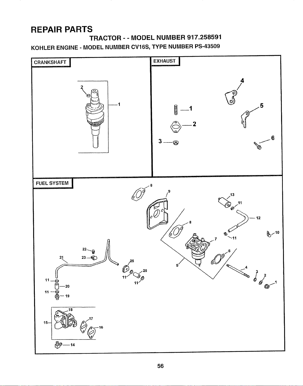
REPAIR PARTS
TRACTOR -- MODEL NUMBER 917.258591
KOHLER ENGINE - MODEL NUMBER CV16S, TYPE NUMBER PS-43509
CRANKSHAFT I
2
\e
----1
!
/9
13
11 __@
0--20
11 u___ t9
f /17
56
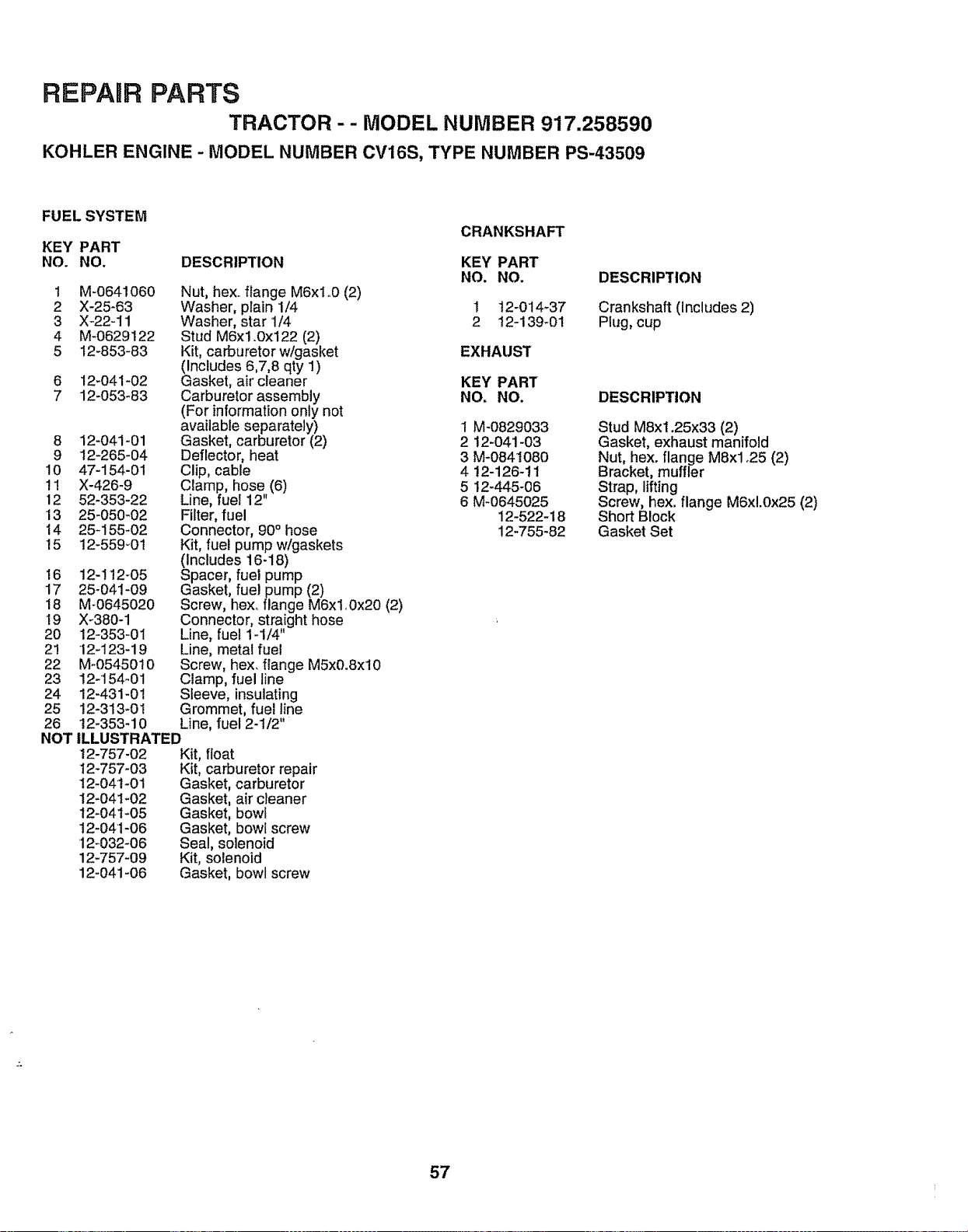
REPARR PARTS
TRACTOR - - MODEL NUMBER 917.258590
KOHLER ENGINE - MODEL NUMBER CV16S, TYPE NUMBER PS-43509
FUEL SYSTEM
KEY PART
NO. NO. DESCRIPTION
CRANKSHAFT
KEY PART
NO. NO.
1 M-0641060 Nut, hex flange M6xlo0 (2)
2 X-25-63 Washer, plain 1/4 1 t2-014_37
3 X-22-11 Washer, star 1/4 2 12-139-01
4 M-0629122 Stud M6x1.0x122 (2)
5 12-853-83 Kit, carburetorw/gasket EXHAUST
(Includes 6,7,8 qty 1)
Gasket, air cleaner
Carburetor assembly
(For information only not
available separately) 1 M-0829033
8 12-041-01 Gasket, carburetor (2) 2 12-041-03
9 12-265-04 Deflector, heat 3 M-0841080
10 47-154-01 Clip, cable 4 12-126-11
11 X-426-9 Clamp, hose (6) 5 !2-445-06
12 52-353-22 Line, fuel 12" 6 M_0645025
13 25-050-02 Filter, fuel 12-522-18
14 25-155-02 Connector, 90° hose 12-755-82
15 12-559-0t Kit, fuel pump w/gaskets
(Includes 16-18)
8 12-041-02 KEY PART
7 12-053-83 NO, NO,
16 12-1t2-05
17 25-041-09
18 M-0645020
19 X_380-1
20 12-353-01
2! 12-123-19
22 M-0545010
23 12-154-01
24 12-431-01
25 12-313-01
26 12-353-10
Spacer, fuel pump
Gasket, fuel pump (2)
Screw, hex. flange M6xl.0x20 (2)
Connector, straight hose
Line, fuel 1-1/4"
Line, metal fue!
Screw, hex. flange M5x0°8xl0
Clamp, fuel line
Sleeve, insulating
Grommet, fuel line
Line, fuel 2-1/2"
NOT ILLUSTRATED
12-757-02
12-757-03
12-04t_01
12-041-02
12-041-05
12-041-06
12-032-06
12-757-09
12-041-06
Kit, float
Kit, carburetor repair
Gasket, carburetor
Gasket, air cleaner
Gasket, bowl
Gasket, bowl screw
Seal, solenoid
Kit, solenoid
Gasket, bowl screw
DESCRIPTION
Crankshaft (includes 2)
PILJg,cup
DESCRIPTION
Stud MSx1.25x33 (2)
Gasket, exhaust manifold
Nut, hex. flange MSx1.25 (2)
Bracket, muffler
Strap, lifting
Screw, hex, flange M6xl.0x25 (2)
Short Block
Gasket Set
57

58

SUGGESTED GUIDE FOR SiGHTiNG SLOPES FOR SAFE OPERATION
SIGHTING
GUIDE
ONLY RIDE UP AND DOWN HILL,
NOT ACROSS HILL
SIGHT AND HOLD THIS LEVEL WITH
SKY LINE OR TREE.
15° MAX.
iiilliLtlJlllllllllllllll HIIIIIIllulllll ::::::
/% Operate your Tractor up and down the face of slopes (not !
H A & greater than 15°), never across the face. Make turns gradu- I
H O ally to prevent tipping or loss of control. Exercise extreme I
caution when changing direc!lon on slopes, i
U
OWNER'S
MANUAL
MODEL NO.
917.258591
IF YOU NEED
REPAIR SERVICE
OR PARTS:
FOR REPAIR SERVICE, CALL
THIS TOLL FREE NUMBER:
1-800-4-REPAIR
(1-800-473-7247)
FOR REPLACEMENT PARTS
INFORMATION AND
ORDERING, CALL THIS
TOLL FREE NUMBER:
1-800-FON-PART
(1-800-366-7278)
FOR CONSUMER ASSISTANCE
HOT UNE, CALL THIS
TOLL FREE NUMBER:
1-800-659-5917
CRAFTSMAN+
16 HP
ELECTRIC START
46" MOWER
Each tracto_ has its own model number', Each engine has
its own model number,
The mode! number for' your tractor will be found on the
model plate located under the seat°
The model number for your engine will be found on the
blower housing of the engine°
All parts listed herein may be ordered from any Sears,
Roebuck and Co, Service Center/Department and most Re-
tail Stores.
WHEN ORDERING REPAIR PARTS, ALWAYS GIVE THE
FOLLOWING INFORMATION:
• PRODUCT =TRACTOR
° MODEL NUMBER - 917.258591
° ENGINE MODEL NO. - CV16S.43509
• PART NUMBER
° PART DESCRIPTION
Your Sears merchandise has added value when you
consider Sears has service units nationwide staffed with
Sears trained technicians.,, professional technicians
specifically trained to insure that we meet our pledge to
you, we service what we sell.
159744 Rev. 1 04,01.97 BW/KFSW
! _!!!! III _ " ........
Printed in U.S,A,
I1_


