
INDEX
1. SAFETY CAUTIONS
2. TECHNICAL DATA
3. STRUCTURAL & PRINCIPLE
3.1 MAIN CONPONENTS
3.2 WORKING PRINCIPLE
3.3 PUMP BLOCK
3.4 GAUGE, SAFETY VALVE
3.5 PRESSURE SWITCH
3.6 ON/OFF
3.7 DRAIN VALVE
3.8 COOLING SYSTEM
4. INSTALLATION & OPERATION
4.1 INSTALLATION
4.2 CHECKING BEFORE OPERATION
4.3 TANK FILLING
5. MAINTAINENCE
5.1 LUBRICANT
5.2 FILTRATION
5.3 AIR HOSE
5. 4 AIR FILTER
5.5 CONDENSATE DRAIN
5.6 ACCESSORIES
6. CIRCUIT DIAGRAM
7. TROUBLESHOOTING
1
SAFETY CAUTIONS
Please read this operation manual carefully before
installation and operation
This series are high pressure air compressor. It compresses atmosphere air go to pressure
20/30Mpa, 3000/4500psi, after be purified and separated by the filter and separa■. It discharge
clean air accords to GB18435-2001 air quality standard.
It is widely be used for breathing of diving and fire fighting paintball PCP shooting and other high
pressure industries by its reliability, portability and easy to use.
make sure the voltage in nameplate meets local power supply.
Make sure the lubricant has been put in before running
Make sure the pressure setting is under 4500psi(310bar)

There is potential danger of pipe burst or connecting fitting blow off under high pressure, please
avoid body too near compressor when it running
For safety Don’t leave compressor and always keep eyes to look at until it reach rated pressure
whether it is automatic stop or manual stop
For safety, always keep eyes on it until it reaches rated pressure and needs to stop.
Double Check the lubricate oil has been put in before Running
2
TECHNICAL DATA
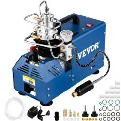
YH-QB01 Portable electric driven HP air compressor
Charging Rate:40-50U/min; 1.5-1.8cfm
Working pressure:100-300bar, 1500-4500psi
No. of stage and cylinder:2
Electric motor : 220v 50hz/110v 60hz, single phase
Cooling : water cooled
Shout down : manual stop/automatic stop(for optional
Pressure indicate : Gauge
Filtration : water/oil separator
Lubricating oil : ISO VG46 or AW 46
Dimension : 360 X 200 X 380mm
Weight : 18kg
Noise : Less than 78 dB(A)
Air hose connection : 8mm quick connect fitting
3
STRUCTURE
3.1 Main components
① power no/off ⑪oil replace drain
② temperature gauge ⑫High pressure hose
③ Siren ⑬oil/ water Filter
④ pressure gauge ⑭Quick connector
⑤ water outlet ⑮intake air filter
⑥ water inlet ⑯drain valve
⑦ Explosion-proof valve ⑰1st Safety valve
⑧ breather /oil inject ⑱overload protection
⑨ Pressure relief valve ⑲Power cord socket
⑩ oil level gauge ⑳Water pump power socket

3.2 Working process
Atmosphere air is compressed through two stage cylinder to reach 20Mpa/30Mpa, 3000/4500 psi.
And the air is filtrated by oil and moisture separator before filling in tanks.
The condensate and oil are separate from air and drain from separator.
3.3 Pump block
The pump block unit is composed of crankcase, crankshaft,
cylinder, piston intake and discharge valves, connect rod,
bearing etc.
It is splash lubrication, direct driven by motor shaft, water
cooled type
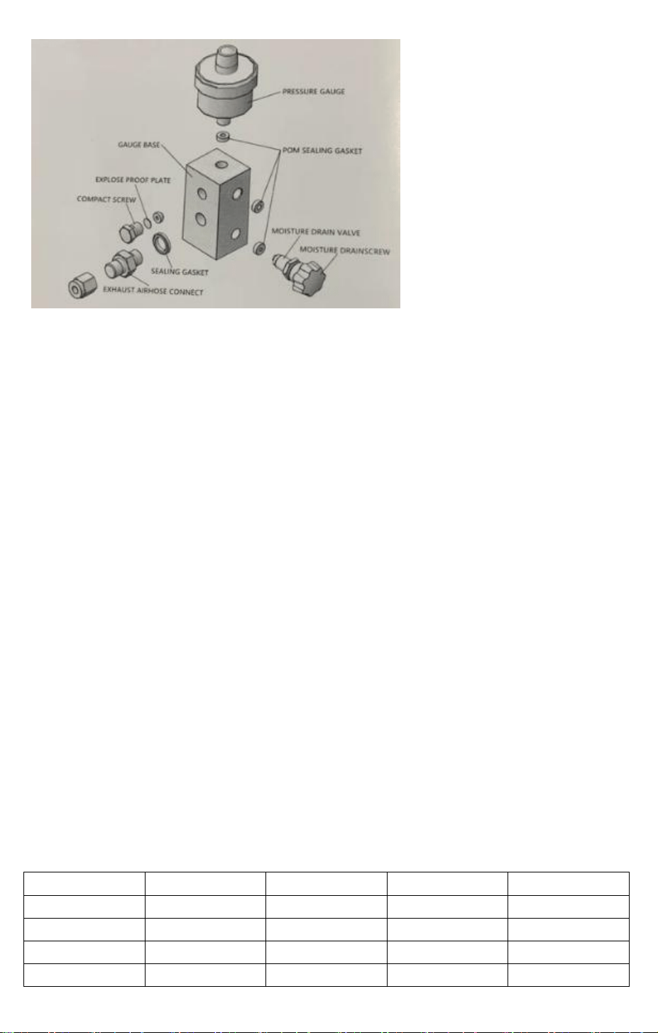
3.4 Gauge&safety valve

The pressure gauge is installed in final stage of the compressor to display discharge pressure.
The safety valve is installed at the place of discharge hole, if the discharge pressure is higher than
preset value, the safety valve will open and release pressure.
Note : release valve will supply protect with more reliable and safety
3.5 Pressure switch(Auto stop version only)
The compressors are preset rated working pressure as per order require. The compressor will stop
automatically when pressure reach rated pressure.
Note : don’t try to adjust it if not get authorized
3.6 ON/OFF
Press ON/OFF button to turn on and turn off compress.
3.7 Drain valve
Open valve in separator and filter to drain moisture and oil from piping when finish tank filling
every time
Note : make sure all drain valve are open when start Compressor
3.8 Cooling system
It is cooled by water, and water container is not included in compressor package.
Best temperature of cool water for working is between
50℃ to 70℃
Max working temperature is 75℃, when is reaches 75℃.
necessary to replace water or stop running the compressor.
The water in container should be no less than 20L/5 gallon, it works better with more water when
cooling down.
4
INSTALLATION AND OPERATION
4.1 Installation
Must use the compressor on the surface which is totally flat and dry. Put water in the container and
place the water pump into the container with no less than 20L/5 gallon fresh water, the water
pump has to be totally immersed in water, to make sure water flows smoothly.

4.2 Checking before operation
Checking
Make sure the voltage in nameplate meets local power supply.
Fill into lubricate oil to around middle place of oil glass.
Note : if the oil level is too high, air valves will easy
carbonize, if oil too low it will result in insufficient lubrication
and piston cylinder sticking
Install breather at oil filling port
Check connect fitting fasten strong and make sure no
Leakage
Check rotary direction of motor
Note : correct direction is cooling wind blow to ■
Trial running
Open the condensate drain valve to make compressor will start in no load.
closed the charging valve to begin a short time test running.
Turn on the compressor, after it runs in steady 3-5 mins
close condensate drain valve and the compressor begin to
pressurize, turn off compressor when it reach the rating
pressure
Caution : Longtime continually running is not suggested, because it may results in
temperature-rising, parts damaged and the machine life shortened
Note : open the drain valves to release high pressure and condensate after every refill operation
4.3 Tank filling
Connect the air tank to compressor with flex hose
Open the condensate drain valve for no loading start
Turn on compressor.
Open the bleed valve, to make sure the pump get start with no load.Turn on the compressor, and
turn the bleed valve off after it runs 30 seconds smoothly, then open the air-charging valve for
filling.
When the pressure reaches the requirement, turn ■ the compressor and close the charging valve,
then turn on the exhaust valve.
The compressor will stop automatically If it Is pressure setting version or the automatic stop
version
(Setting method : The red knob above the rotary pressure gauge can make the setting pointer stay
above the required number.)
Please shut down the power supply and close air-charging
valve if there’s any emergency in air filling.
Note : advise the paintball tank no more than 3 liters
4500psi 30Mpa, fill big tank will cause compressor over time
running, normal continue run no more than 1 hour
5
MAINTENANCE
General maintenance interval
Every Tine
50h
100h
annually
Lube Oil
△
◆
◆
◆
Air intake filter
△
◆
◆
Safety valve
◆
Air hose
◆
△ Check ◆replace
5.1 Lubricant oil
Oil level must be checked every time;
First time oil change : 50 hours, 0.5-0.6 liters
Regular oil change : 100 hours or annually
Lubricant oil features : ISO VG46, AW46
Warning : it is forbidden to mix different brand or ISO grade oil for lubricate, recommend MOBIL
827/829 or equivalent
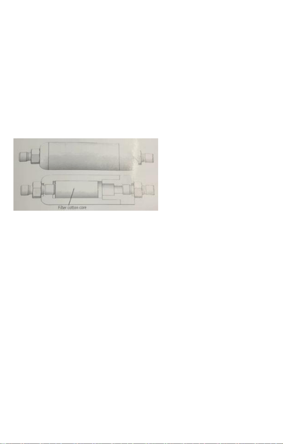
5.2 Filtration for air
The better outlet air quality will be got if use extra purification,
filter elements must be highly efficient fibrous materials and must be replaced periodically.
5.3 High pressure air hose
The air hose must be replaced regularly 1000 hours or
annually, bending radius does not exceed 250mm. With
8mm quick connector, connect directly to tank valve fitting.
5.4 Air filter
Us compressed air to blow air filter to clean dust. The air filter
must be changed every 100 working hours or annually.
Note : We would suggest to change filter every 50 hours if the compressor is used in dusty
environment.
5.5 Condensate drain
Drain condensate after every refill, Open the drain screw to
drain out Normal condensate is milk white or brown white
with a little few resident oil,
If the condensate is in black or oil smell, check lube oil quality or change oil
5.6 Accessories come with
Water pump
Water pipe
Air filling hose
Breather
Spare parts kit

Spare parts list and drawing
1 screw nut 9 discharge base spring
2 2nd stage discharge connect 10 1st stage intake valve
3 Sealing washer 11 intake air filter
4 2nd stage cylinder head 12 2nd piston
5 2nd stage discharge valve 13 up gasket upper
6 2nd stage valve base 14 42mm cylinder
7 2nd stage cylinder 15 connecting rod
8 1st stage discharge valve 16 Motor stator
17 breather /oil inject 22 Shock cushion foot
18 1st Safety valve 23 Motor bracket
19 down gasket 24 Crankcase
20 Ventilation hood 25 Crankcase side cover
21 Fan blade 26 Heat dissipation catheter
6
CIRCUIT DIAGRAM

Note : required 15AMP home breaker, do not use power strip
Panel with long power core
7
TROUBLESHOOTING
FAULT
REASONS
SOLUTION
Can’t start
1. motor breaker jump
2.Use power strip
panel with long core
3. Inside pressure high
1. press motor reset button
2. Use the wall socket
3. Open drain valve to release
Over heat
1. wrong fan rotary direction
2. Bad ventilation
3. Long time running
1. Correct it
2. Correct it
3. No more than 1 hours continually work
Slow filling
1. fitting / gasket leak
2. Pistonring valve wear
3. Safety valve blow
1. tighten again
2. Replace
3. Replace
Can’t turn
round
1. piston locked
2. Bad lubricate
1. Replace
2. replace
Smoke
1. high oil temperature
1. stop and cool down
Noise and
shake
1. connect bar/bearing damage
2. Belt loose
3. Not flat ground
1. Replace
2. tension belt
3. Correct it
Breather
blow away
1. high pressure in crankcase
1. check each stage valve and repair
