
Shenzhen Xtooltech Intelligent Co., LTD
User Manual
D9EV Smart Diagnostic System
Version 1.4
Revise date 2024/05

I
Please read this user manual carefully before using the N9EV Smart Diagnostic System, referred to as the “Scan Tool”
throughout this document. When reading the manual, please pay attention to the words “Note” or “Caution”, and read them
carefully for appropriate operation.
OPERATION INSTRUCTIONS
For safe operation, please follow the instructions below:
Keep the device away from heat or fumes when in use.
If the vehicle battery contains acid, please keep your hands and skin or fire sources away from the battery during
testing.
The exhaust gas of the vehicle contains harmful chemicals. Please ensure adequate ventilation.
Do not touch the vehicle cooling system components or exhaust manifolds when the engine is running due to the
high temperatures reached.
Make sure the car is securely parked, Neutral is selected or the selector is at the P or N position to prevent the
vehicle from moving when the engine starts.
Make sure the (DLC) Diagnostic Link Connector is functioning properly before starting the test to avoid damage to
the Diagnostic Computer.
Do not switch off the power or unplug the connectors during testing. Doing so may damage the ECU (Electronic
Control Unit) and/or the Diagnostic Computer.
CAUTIONS!
Avoid shaking, dropping or dismantling the scan tool as it may damage the internal components.
Use only your fingertips to touch the LCD screen. Hard or sharp objects may damage the scan tool.
Do not use excessive force;
Do not expose the screen to strong sunlight for a long period.
Please keep the scan tool away from water and moisture.
Store and use the scan tool only within the temperature ranges identified in the Technical Specifications section.
Keep the unit away from strong magnetic fields.
AFTERSALES-SERVICES
XTOOL strives to provide best-in-class support!
E-Mail: s[email protected]
Tel: +86 755 21670995 or +86 755 86267858 (China)
Official Website: www.xtooltech.com

i
C
ONTENT
OPERATION INSTRUCTIONS ............................................................................................................................. I
CAUTIONS! ...........................................................................................................................................................I
AFTERSALES-SERVICES ................................................................................................................................... I
CONTENT ............................................................................................................................................................. I
1. GENERAL INTRODUCTION ......................................................................................................................3
Main Units ......................................................................................................................................................................... 3
Vehicle Connection ........................................................................................................................................................... 5
WIFI connection ...................................................................................................................................................................................... 5
Wired Connection ...................................................................................................................................................................................5
Self-test......................................................................................................................................................................................................6
2. DIAGNOSTIC ............................................................................................................................................. 7
Beginning Diagnostic Testing ............................................................................................................................................8
Vehicle Selection .....................................................................................................................................................................................8
Diagnosis functions................................................................................................................................................................................9
ECU Coding & Programming...........................................................................................................................................................16
3. BATTERY PACK DETECTION ................................................................................................................18
4. CAN INSPECTION ................................................................................................................................... 18
5. COMPONENT TEST ................................................................................................................................ 20
Compressor detection ..................................................................................................................................................... 20
OBC detection ................................................................................................................................................................. 20
Component test-48V motor detection ..............................................................................................................................21
DCDC detection .............................................................................................................................................................. 21
6. SPECIAL FUNCTIONS ............................................................................................................................ 21
ABS BLEEDING .............................................................................................................................................................. 21
OIL RESET ......................................................................................................................................................................24

ii
EPB ................................................................................................................................................................................. 26
SAS ................................................................................................................................................................................. 27
BMS RESET ....................................................................................................................................................................28
INJECTOR CODING .......................................................................................................................................................29
DPF REGENERATION ................................................................................................................................................... 31
TPMS RESET ................................................................................................................................................................. 34
7. REPORT ................................................................................................................................................... 37
Replay ............................................................................................................................................................................. 39
File Manager ................................................................................................................................................................... 40
Data View ........................................................................................................................................................................ 40
8. UPDATE ................................................................................................................................................... 42
Update Software ..............................................................................................................................................................42
Delete Software ...............................................................................................................................................................43
9. WARRANTY & SERVICES ......................................................................................................................43
10. REMOTE ASSISTANCE .......................................................................................................................... 43

3
1. GENERAL INTRODUCTION
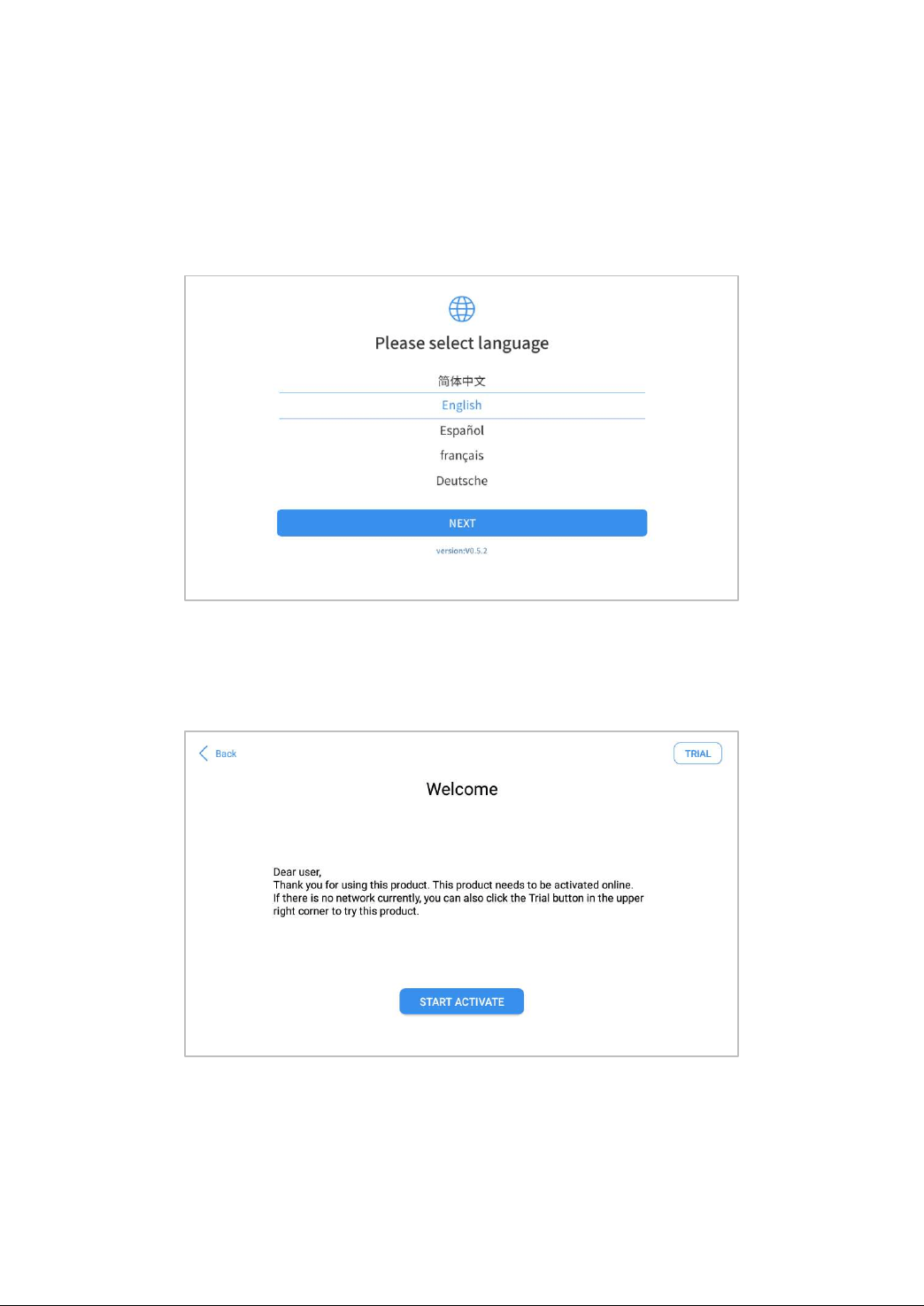
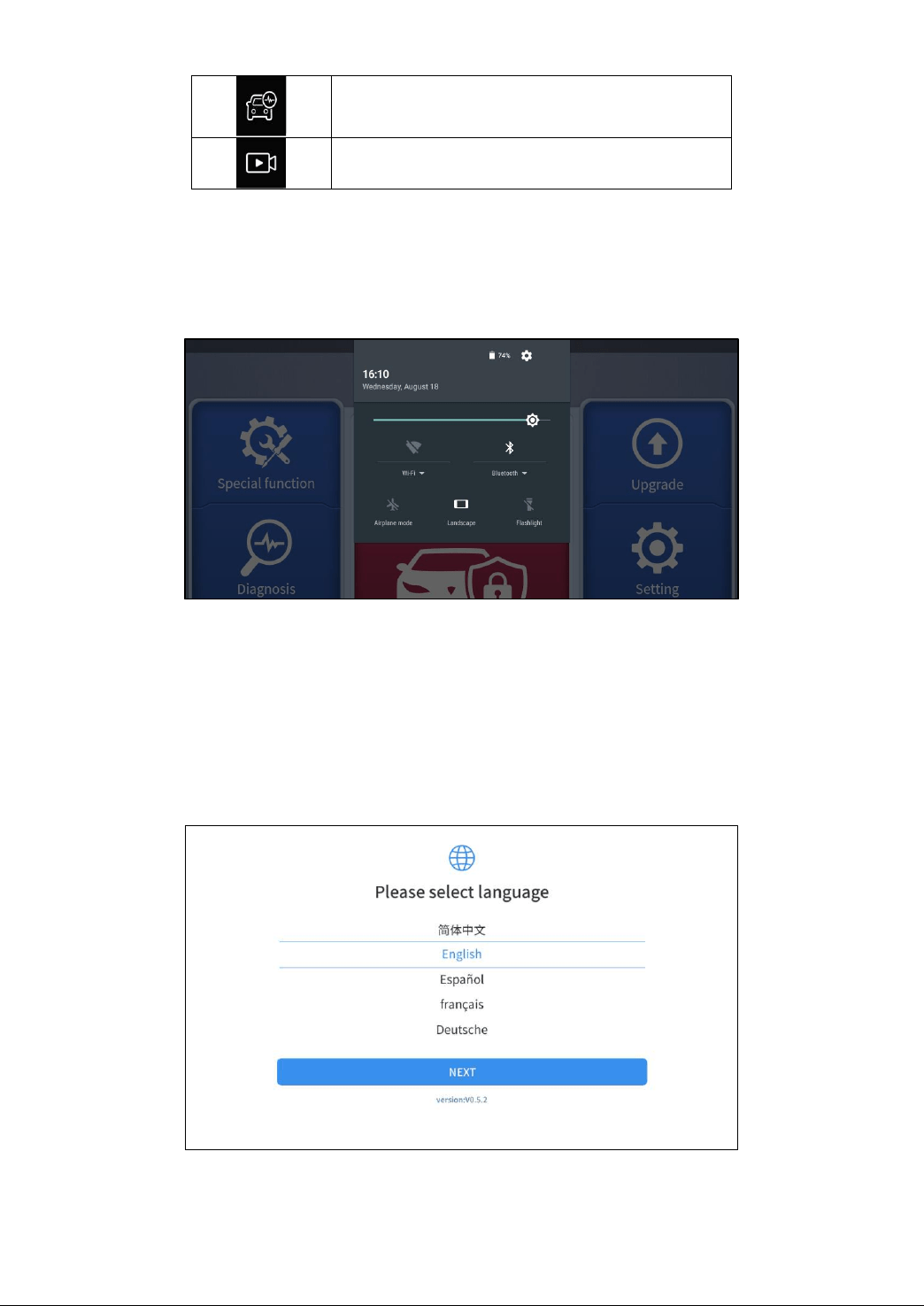
The XTOOL N9EV smart diagnostic system (referred to as the “Scan Tool”) is an advanced scanning tool based on the
Android operating system. It supports multiple languages and is suitable for different countries and regions. The
advantage of this OBD-II (On-Board Diagnostics version 2) scanner is its comprehensive functions and its ability to quickly
provide the user with more accurate diagnostic information.
N9EV Smart diagnostics System main units included:
Tablet: P902
Wireless Diagnostic Module: V207 VCI (Vehicle communication interface) box
Other accessories
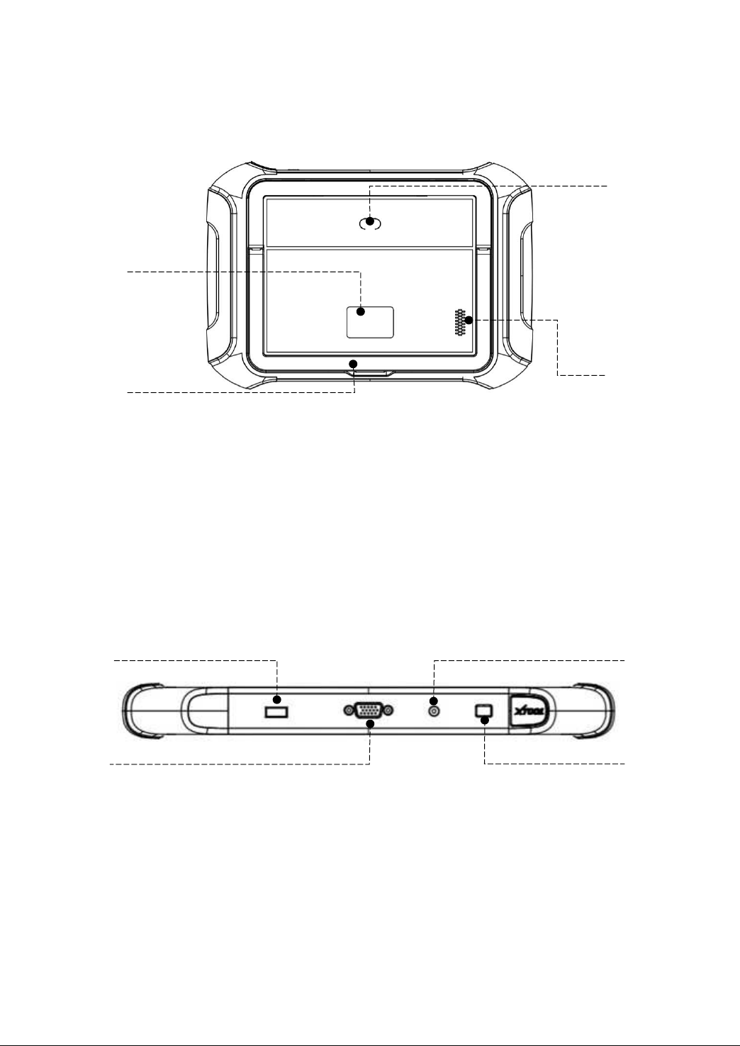
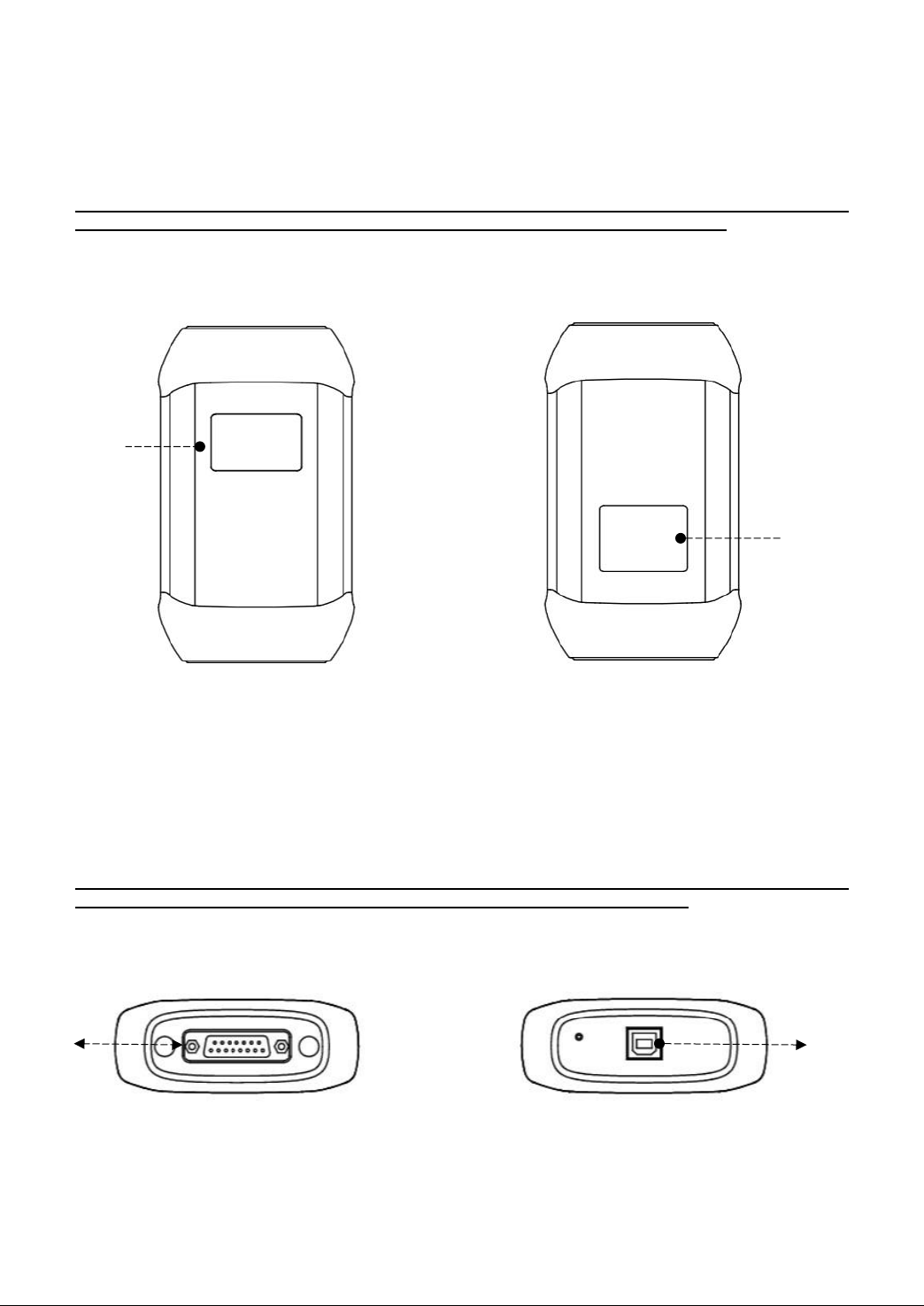
MAIN UNITS
Tablet
1. 9.7-inch touch screen
2. Type-C Port
3. Power Button – Long press to turn
off/on the tablet, short press to enter
sleeping mode
4. Rear Camera
5. Nameplate
6. Holder
7. Speaker

4
VCI Box
1. DB15 Port
2. Display with vehicle voltage
3. Type-B Port
OBD2-16 Adapter
1. OBD Male Connector – Plug into vehicle’s
DLC port
2. DB15 port – Connect to main cable
DB15 Main Cable
1. DB15 Port – to OBD2-16 Adapter
2. DB15 Port – to VCI
3. 12V DC Power Input Port

5
VEHICLE CONNECTION
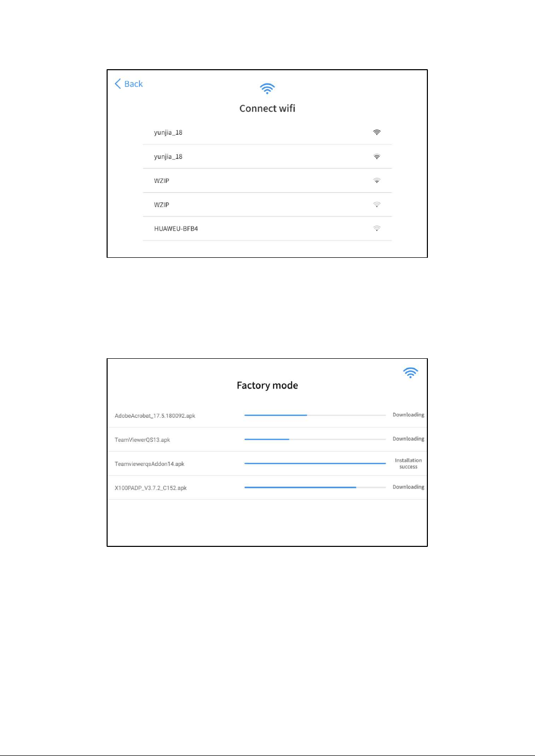
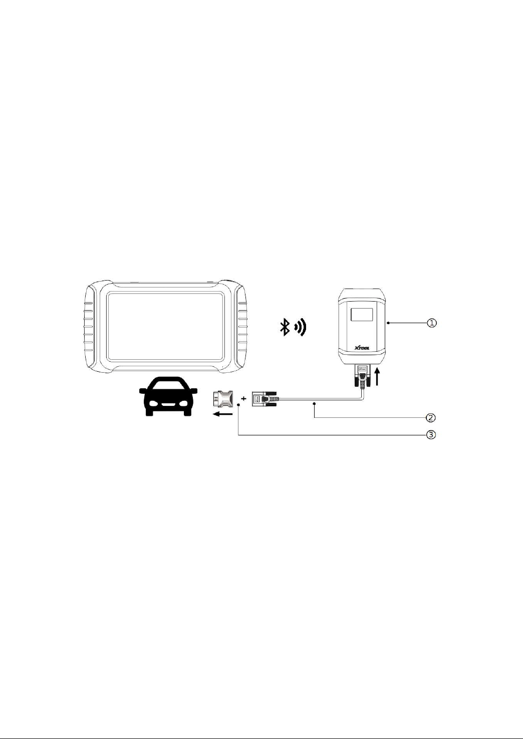
WIFI CONNECTION
The WIFI connection method is shown in the figure below:
The scan tool must be connected to the vehicle’s OBD-II port so that the tablet can establish correct vehicle
communication. Please perform the following steps:
1 Turn on the tablet
2 Connect VCI with Vehicle via main test cable and OBD adapter, make sure WIFI connection works fine
3 Switch on the ignition and tap on the Diagnostic application to start your diagnosis.
⚠
Note: The vehicle’s DLC is not always located under the dash; for the location of the DLC, please refer to
the vehicle owner’s manual. Some older vehicles are not compatible with the OBD
Ⅱ
-16 adapter, please make
sure you’re using the correct adapter.
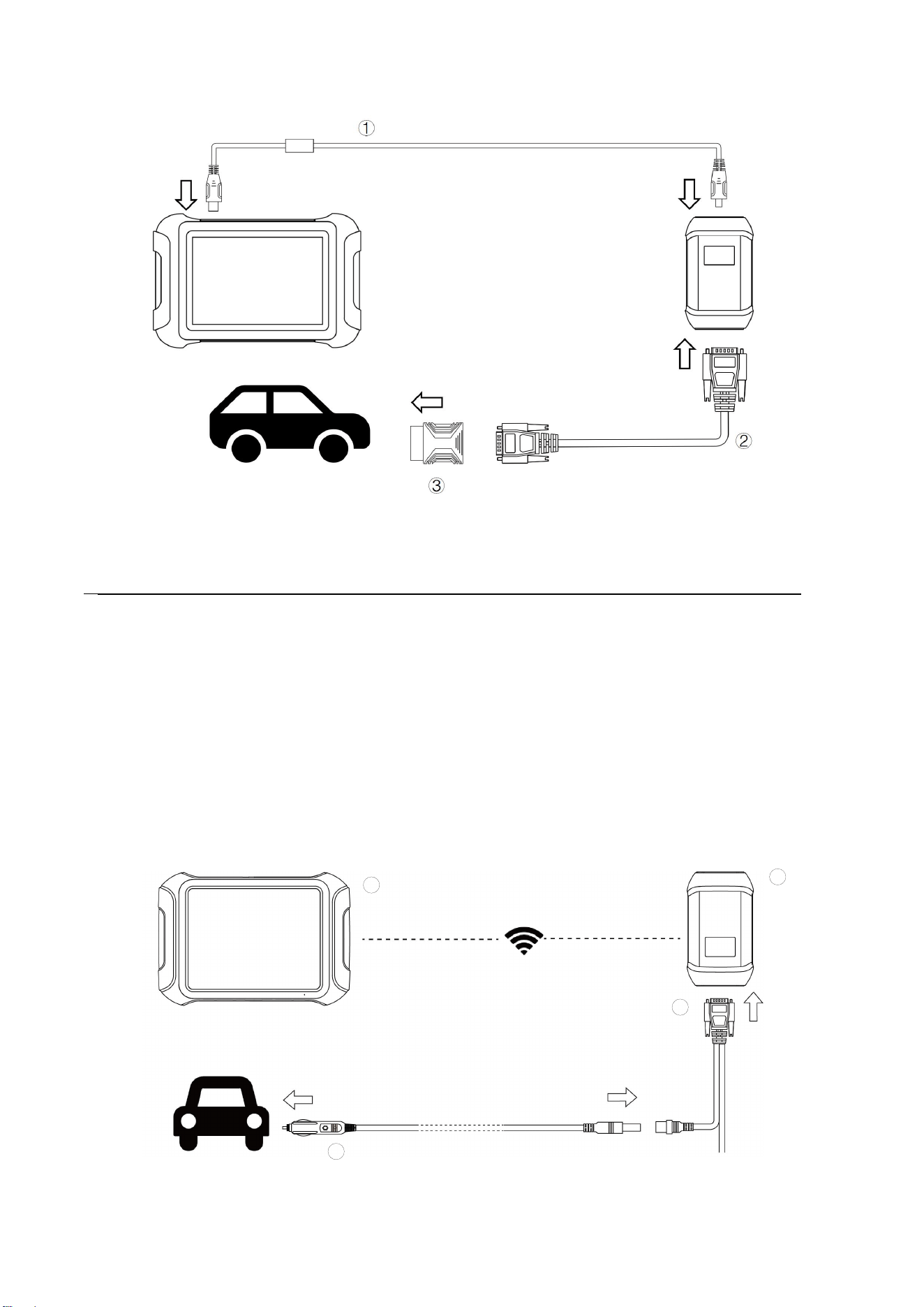
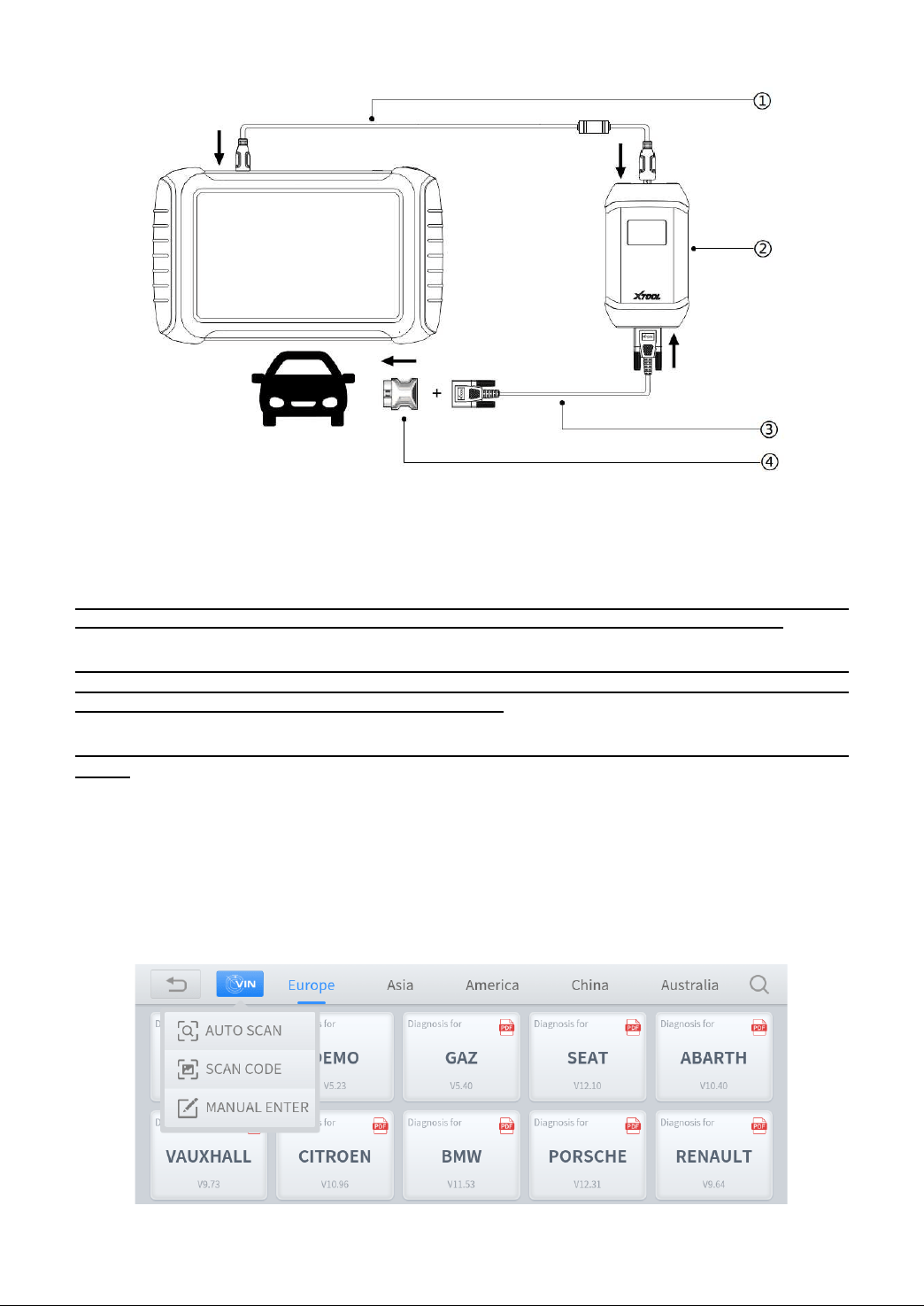
WIRED CONNECTION
When using functions such as ECU programming & coding, please use the USB 3.0 to TYPE-B main cable to connect the
tablet to the VCI box to prevent the failure of function execution due to unstable data transmission and thus any other
damage.
6
1. Type-C to Type-B cable
2. DB15 Main Test cable
3. OBDII-16 Adapter
For models with DoIP protocol communication, please be sure the device is connected to vehicle by wire.
SELF-TEST
The self-test is mainly used to detect whether there is a fault in the internal hardware of the device. When performing the
self-test function, please do not connect the VCI box or tablet directly to the vehicle’s OBD port, otherwise irreversible
damage may be caused to your vehicle!
• Plug the power cord into the 12V DC port of the VCI box
• Enter the following path: Main Menu>>Setting>>Self-test, make sure the device is not connected to any vehicle, click
OK to perform self-test function
1
4
2
3
7
1. Cigarette Lighter
2. DB15 Main test cable
3. VCI box
4. Tablet
Precautions for Diagnosis
1. The voltage range on the car: +9~+36V DC;
2. When testing some special functions, the operator must operate according to the prompts and meet the test conditions.
For some models [special functions], the conditions that need to be met are: engine water temperature 80 ℃~105 ℃, turn
off headlights and air conditioners, keep the accelerator pedal in the released position, etc.;
3. The electronic control systems of different models are very complicated. If you encounter situations where it is
impossible to test or a large amount of test data is abnormal, you can search for the ECU of the vehicle and select the
menu for the model on the ECU nameplate;
4. If the vehicle type or electronic control system to be tested is not found in the diagnostic function, please upgrade the
vehicle diagnostic software to the latest version using the Updates menu or consult the XTOOL technical service
department;
5. Only wiring harnesses provided by XTOOL and designed for the scan tool are permitted to be used with this scan tool to
avoid damage to the vehicle or the scan tool;
6. When running a Diagnostics function, it is forbidden to shut down the scan tool directly. You should cancel the task
before returning to the main interface and then shutting down the scan tool.
2. DIAGNOSTIC
The D9EV supports two diagnostic modes, EV mode and normal diagnostic mode, both of which support diagnostics, but
there is a difference in the models covered by their diagnostic functions. EV mode supports diagnostics for pure electric
vehicles and hybrid models only. General diagnostic mode supports gasoline, diesel, hybrid and pure electric models. It
should be noted that some pure electric vehicles can only be used in EV mode, such as Tesla. In addition to diagnostic
functions, EV mode also features battery pack dynamic inspection and component testing.
8
The diagnostic application can read ECU information, read and clear DTC (Diagnostic Trouble Codes) and check live data
and freeze frame data. The Diagnostic application can access the ECU of various vehicle control systems, including the
Engine, Transmission, Anti-lock Braking System (ABS), Airbag Safety Restraing System (SRS), Electronic Parking Brake
system (EPB) and perform many types of actuation tests.
BEGINNING DIAGNOSTIC TESTING
After the tablet device is properly connected to the vehicle, you could start the vehicle diagnosis.
VEHICLE SELECTION
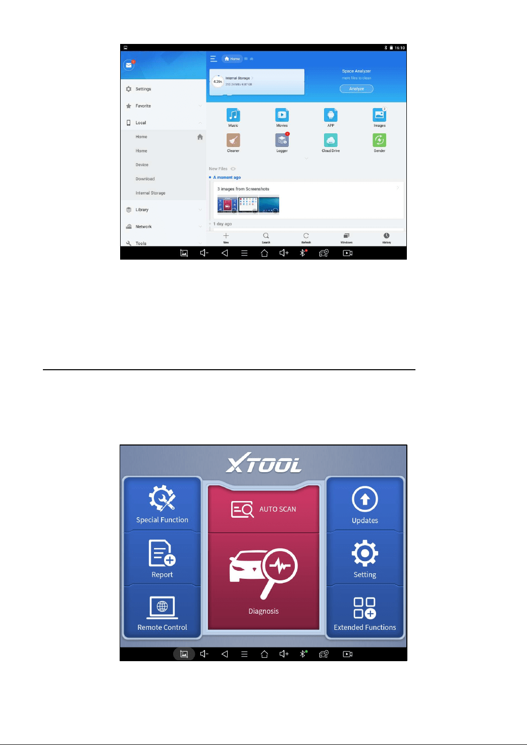
Click the “Diagnostic” icon on the main screen and get into the diagnostic menu. Like the immobilizer menu, the brands
will be shown on the screen. Select the region of your vehicle, click the correct brand, and start the diagnostic process.
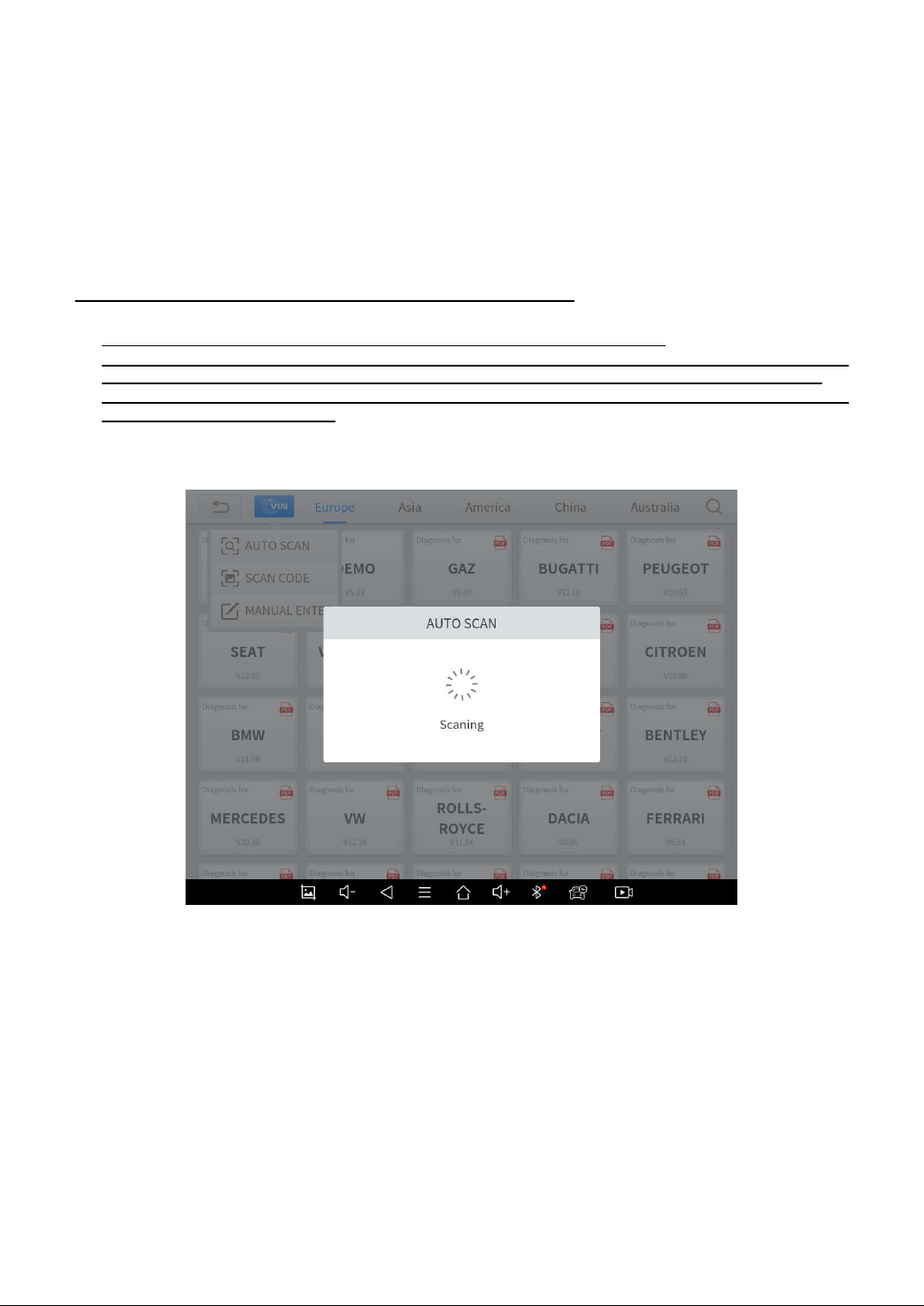
For some of the vehicle brands (like Volkswagen), when you click on the software, there are several ways to select the
model or system you want to run a diagnostic, including Automatic Detection, Manual Selection, and System Selection.

9
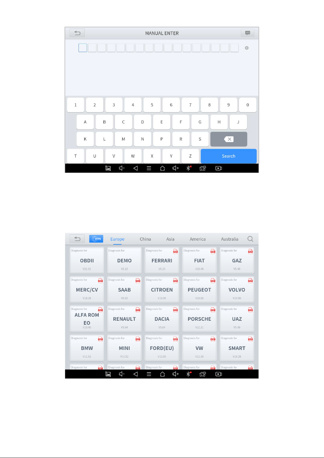
Automatic Detection will automatically identify the vehicle's VIN code, and then read the information of your target
diagnostic object. If you choose "Manual selection", then you can continue to select the vehicle brand, year, and model of
the vehicle in the sub-menu to diagnostic the vehicle. Enter "System Selection", you can also diagnose the vehicle
according to the system according to your needs after selecting the model.
OBDII menu supports reading the common fault codes in the engine. The DTCs may not be the same when
compared with using common diagnostic software.
DEMO is a demonstration program. You can perform basic diagnostic functions without connecting to the car. .
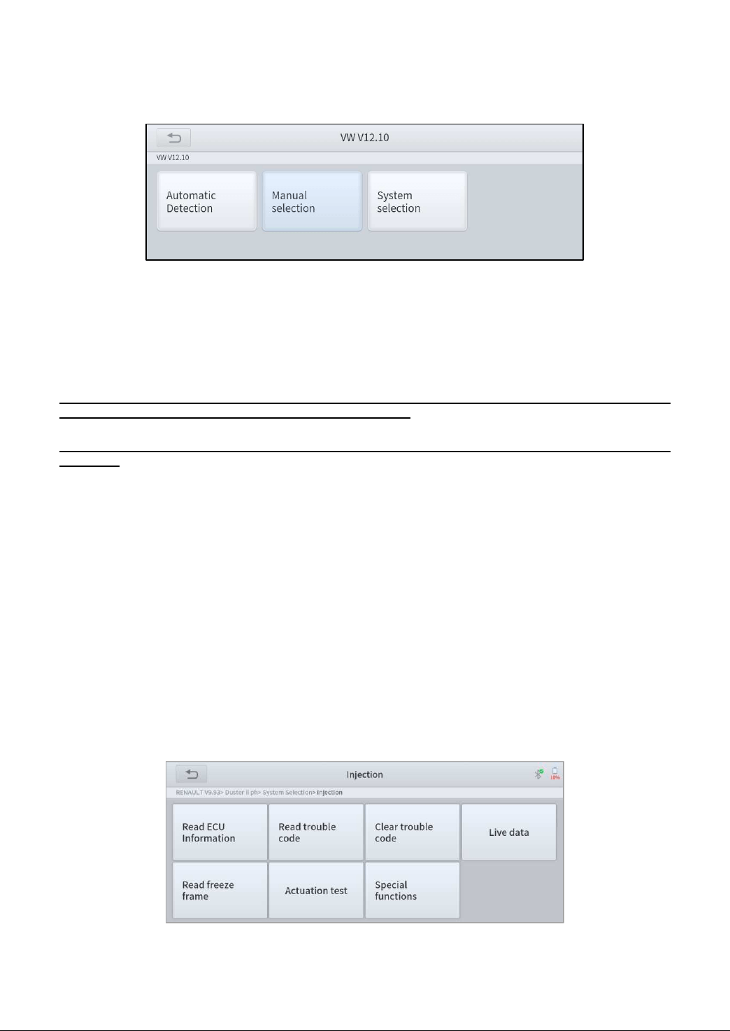
DIAGNOSIS FUNCTIONS
Diagnostics functions supported by the scan tool are listed below:
Read ECU Information
Read/Clear Trouble Code
Read Live Data
Freeze Frame
Actuation Test (Bi-Directional Control)
Special functions
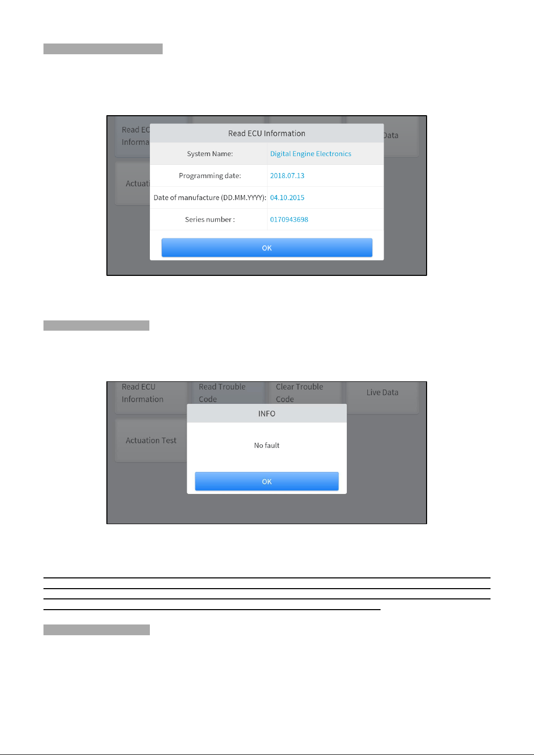
READ ECU INFORMATION
This function is to read ECU version information and is the equivalent of "System Identification" or "System
Information” in some electronic control systems. These equivalent terms all refer to reading ECU-related software and
hardware versions, models and production date of diesel engines, part numbers, etc. This information is helpful when
recording maintenance records and ordering new parts

10
READ TROUBLE CODE
In the process of diagnosis, if the device shows “System is OK” or “No Trouble Code”, it means there is no related trouble
code stored in ECU or some troubles are not under the control of ECU. Most troubles are mechanical system troubles or
executive circuit troubles. It is also possible that the signal of a sensor may be inaccurate but within limits, which can be
examined using Live Data.
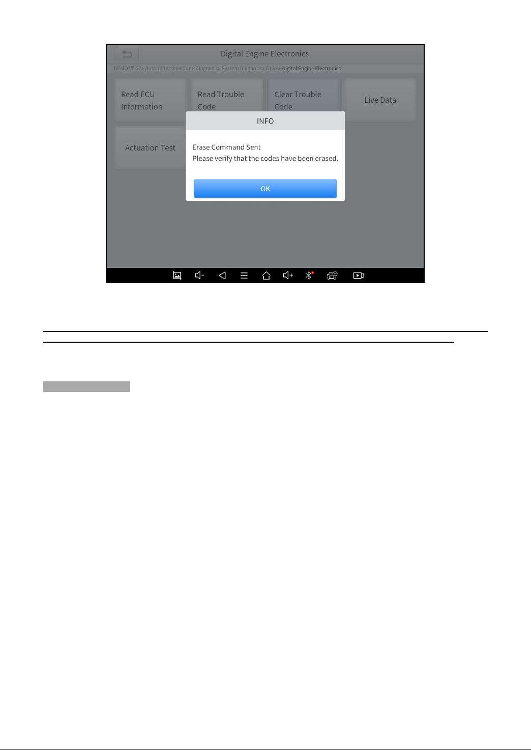
CLEAR TROUBLE CODE
It allows for clearing current and historical trouble codes stored in the ECU memory, under the premise that all the troubles
have been resolved.
Some troubles are immediately detected by the ECU with the key in the run position and without the engine running.
Other troubles are not detected until very specific test conditions are met such as engine coolant temperature within a
range, speed within a range for a duration of time, throttle percentage within a range, etc.
If the trouble codes are erased when the trouble remains unresolved, the trouble code will reappear in the ECU the next
time the ECU performs the specific diagnostic test for that trouble.
If the trouble is resolved but there is a stored trouble code, sometimes the ECU will detect the resolution and clear the
trouble code or more likely, classify it as “historical” trouble.
If the trouble is resolved and the user clears the trouble codes, the trouble history will be cleared.
If the user intends to have another colleague or mechanic investigate the problem, it is not recommended for the user to
clear the trouble code since doing so may erase information helpful to others who may investigate the issue.
11
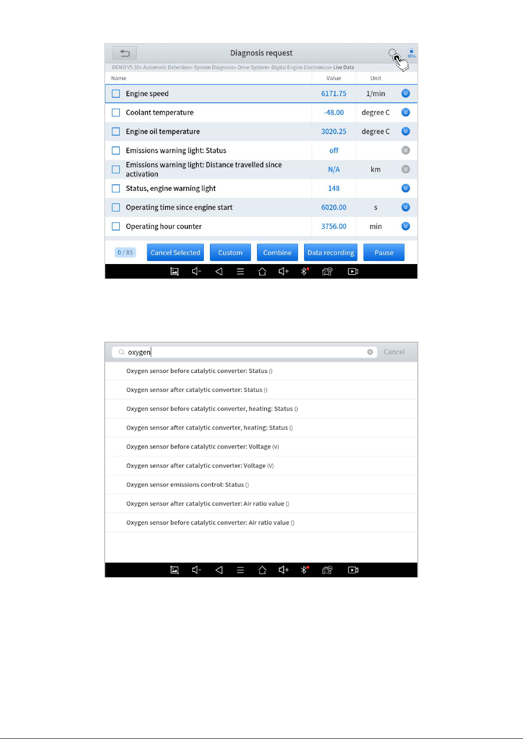
READ LIVE DATA
Real-time information about various sensors is called “Live Data”. Live Data includes parameter identifications (PIDs) of
the running engine such as oil pressure, temperature, engine speed, fuel oil temperature, coolant temperature, intake air
temperature, etc. Based on these parameters, we can predict directly where the problem lies, which helps to narrow the
scope of maintenance. For some vehicles, during their actual operation, the problems such as performance characteristics
or sensitivity reduction, can be evaluated using live data.
!Note: The speed may vary depending on the speed of data sent from the vehicle and the number of data parameters
being shown.
Click the magnifying glass on the top right, you can search for related PIDs based on keywords
12
Custom
The scan tool includes support to select and show multiple PIDs. Click Display All to display all PIDs. This enables you to
see relationships between data parameters.
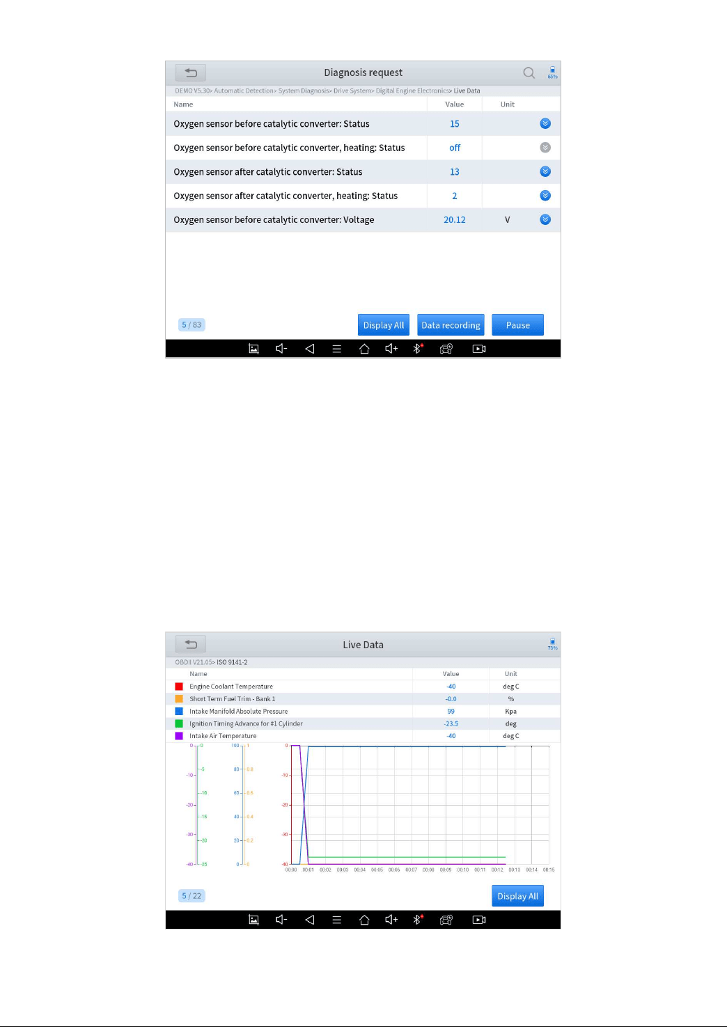
Graph
Click Graph to switch to multi-line graph mode. Click List to display all selected PIDs as a list
13
Combine
The scan tool includes support to select multiple PIDs and click Combine to combine different graphs into one chart.
Data recording
The scan tool supports recording the current data values in the form of text. You can view the recorded files in Reports-
>Data Replay.
Pause
Click this button to pause the recording timeline. It freezes the data display, for closer examination and review.
14
FREEZE FRAME
When the signal of the sensor is abnormal, the ECU will save the data at that moment of failure to form a freeze-frame. It
is usually used to analyze the reasons that may lead to component(?) failures.
The live data items supported by vehicles of different brands are not the same, so the freeze frames displayed when
diagnosing vehicles of different brands may also be different. Some vehicles may not have the option of a freeze-frame
which means that the model does not support this function.
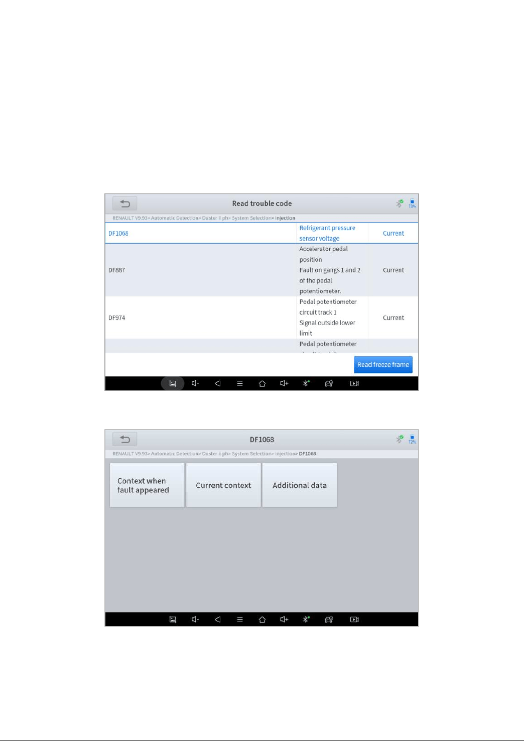
Take Renault Duster ii ph as an example. After selecting the system to enter the lower freeze frame menu, the device
will list all the fault codes under the system.
Users can click on a fault code, such as DF1068 to view the freeze frame recorded by the car when the fault code occurs,
including context when the fault appeared, and current context and additional data.
15
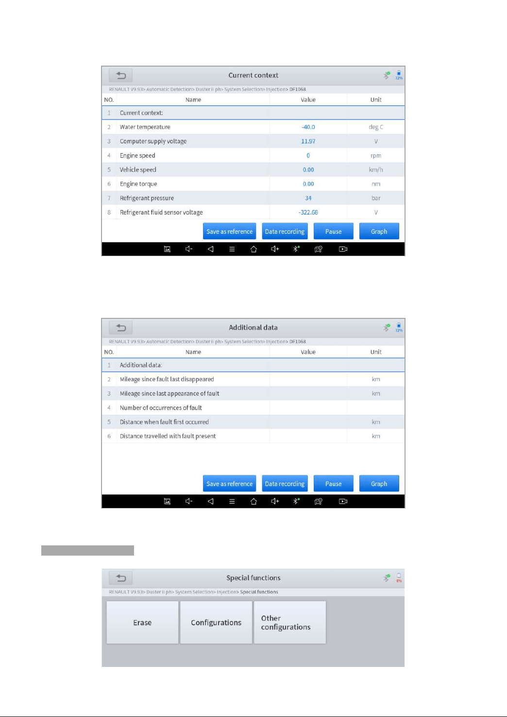
Context when fault appeared: record the live data when fault appeared to help the user to know the vehicle status.
*Some vehicles don't support this function; users will get a prompt when they click the menu.
Current context: Displays the current live data stream associated with the DTC
Additional data: record other data related to the fault
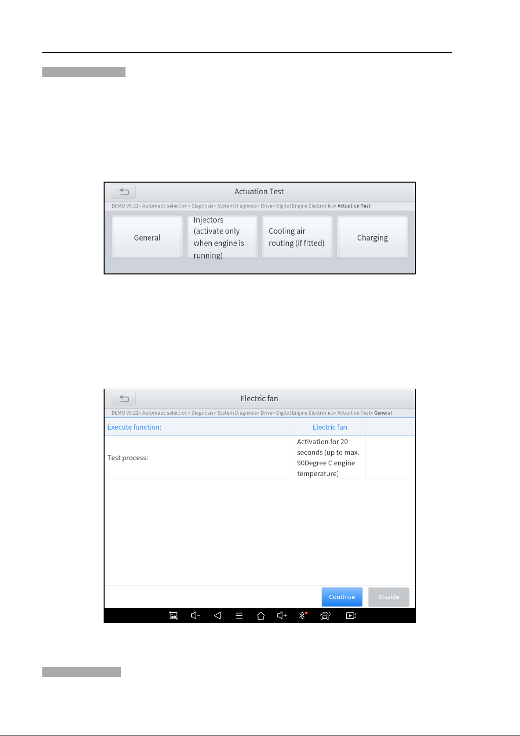
ACTUATION TEST (BI-DIRECTIONAL CONTROL)
Actuation test, also known as bidirectional control, is a generic term used to describe sending and receiving information
between one device and another. This function is used mainly to judge whether these actuating components of the engine
are working properly.
The vehicle engineers responsible for designing computer control systems programmed them so a scan tool could request
information or command a module to perform specific tests and functions. Some manufacturers refer to bidirectional
controls as functional tests, actuator tests, inspection tests, system tests or the like. Reinitialization and reprogramming
also can be included in the list of bidirectional controls.
This function allows the device to send information to and receive information from, vehicle control modules. For example,
in the case of OBD II generic information Mode 1 (which relates to data parameters), the scan tool user initiates a request
for information from the powertrain control module (PCM), and the PCM responds by sending the information back to the
scan tool for display. Most enhanced scan tools also can actuate relays, injectors and coils, perform system tests, etc.
Users could check the individual part to see what is working properly by actuation test.
16
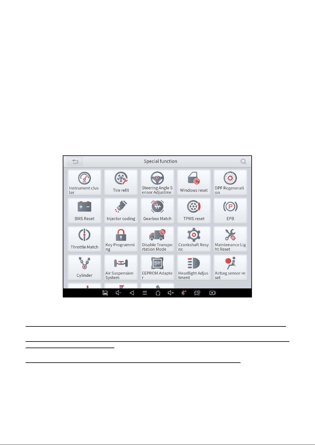
SPECIAL FUNCTIONS
Usually, special functions provide various reset or re-learning functions menus for most vehicle systems. You can easily
and quickly solve some faults through special functions for your car. After some functions are successfully executed, fault
codes will be generated, which need to be cleared manually after the car is running for a little while which could include a
single start of the engine or multiple warm up cycles.
And under each system, you can view the special features supported by that system. Different models and systems often
have different special functions. Even for the same system of the same model, the years and ECU type may lead to
different special functions supported.
ECU CODING & PROGRAMMING
Since the introduction of OBD II and leading up to modern Hybrids and EVs, computers, and software in cars have been
expanding at an exponential rate. In-car software is becoming one of the leading needs for service, and updating software
may be the only way to fix some of these issues:
• Drivability
• Fuel Efficiency
• Power Loss
• Fault Codes
• Durability of Mechanical Parts
17
The Programming and Coding function is used to re-flash the vehicle control modules, which allows you to update the
computer software of the vehicle to the latest version, as well as to reprogram adaptive data of certain components after
making repairs or replacements.
There are two general types of programming operations:
ECU Coding
ECU Coding, also known as Teach-in Program, or Component Adaptation, is used to reprogram adaptive data for
electronic control modules after repairs or replacements of parts.
*NOTE: Codable control modules/components are system-specific, which means that not all control modules are
codable.
ECU Programming
ECU Online programming means a user could download the latest version of the software from the online server database
through Internet access (this procedure is done automatically when the tablet is connected to the Internet, so there is no
need to check for software updates yourself), and reprograms the newest version into the ECU of vehicles.
Reprogramming involves taking the following steps, but there may be changes related to the vehicle type, so please
complete the operation according to the actual situation and software prompts.
Available programming or coding operations vary by test vehicle. Only the available operations are displayed in the
tablet menu.
The programming function applies only when the vehicle is connected with a VCI device, which serves as a
PassThru interface to establish communication with and transfer data to the vehicle’s ECU.
Before applying the ECU programming function, please make sure that the tablet computer is connected to a stable
Internet connection so that the tablet computer can access the vehicle manufacturer's server for update services.
Selecting the programming or coding function will open a menu of operating options, which differs depending on the
vehicle’s make and model. Selecting a menu option either displays a programming interface or opens another menu
containing other options. When performing programming or coding operations, follow all instructions on the screen.
The way and content of the information displayed on the screen differ depending on the type of operation being
performed.
NOTE: For some vehicle brands, such as BMW, the ability to program a module is limited to the number of times
it has already been programmed and the hardware version of the control module itself.
IMPORTANT
When reprogramming onboard, please always make sure the vehicle battery is fully charged and in good working
condition to avoid the operation failure caused by the abnormal voltage below the proper operating voltage. Sometimes
the failure can be recovered, but the failed reprogramming can also cause a fault in the control module. We recommend
connecting an external battery maintainer to the vehicle to ensure a steady voltage is maintained throughout programming.
The required voltage differs by the vehicle manufacturer. Consult vehicle manufacturer for correct voltage to be
maintained.
Occasionally a flash update procedure may not complete properly. Common causes of flash errors include
poor cable connections between the tablet, VCI, and vehicle, the vehicle ignition being switched off before the
flash procedure is complete, or low vehicle battery voltage.
If the process quits, recheck all the cable connections to assure good communications and initialize the flash
procedure. The programming procedure will automatically repeat if the previous operation does not succeed.
Please use this feature with caution and it is not recommended for non-professionals.
18
3. BATTERY PACK DETECTION
This function supports the detection of different types of battery packs for the mostly EV models on the market. It can read
the individual cell's voltage and each single temperature probe data of the vehicle’s battery pack.
It also allows checking the total voltage and the voltage of each cell in the battery pack and marks them with different
colors according to their value and range. You can easily get the cell position of Max/Min Volt and Temp by this functions,
it helps you locate the fault faster.
Click Set as Reference to save the current data as the reference value range. if the value is out of the reference range,
then the color of that cell will turn red automatically.
4. CAN INSPECTION
If the model of your battery pack is not covered, you can use the CAN INSPECTION function to collect data. It can detect
the pin voltage and custom the pin configuration, and support to check the baud rate, can automatically identify the OBD
pin voltage, and can quickly identify the CAN bus.
Select More to enter the CAN INSPECTION function
19
Complete the vehicle information, and select the NEXT
Select the Pin Config to detect the voltage of pin
Click Start to confirm the settings and select OK to collect the data
20
Note: If the detection results do not match the actual vehicle configuration, the corresponding pins may be faulty.
5. C
OMPONENT
T
EST
This tool supports different test functions for different components, such as compressor, DCDC, 48V motor and OBC.
After the repairment, there is no need to install the component back into the vehicle, users can test it off-vehicle to check
whether the component is in good working condition.
COMPRESSOR DETECTION
This function supports the off-vehicle drive of the compressor module. After the compressor module is repaired, it does not
need to be tested back on the vehicle. First, connect to the power supply according to the voltage identification on the
compressor nameplate, and then connect to VCI according to the jumper diagram. By doing this, you can achieve one-key
start of the compressor.
OBC DETECTION
This function enables the off-vehicle drive of the OBC module. After the OBC module is repaired, it does not need to be
tested back on the vehicle. First, connect the M812 box and VCI in series, and then connect the OBC and M812 box
according to the jumper diagram. After connecting AC power and load to OBC, you can achieve one-key start of OBC.
! IMPORTANT: After data collection, please contact XTOOL Technical Support Center
21
COMPONENT TEST-48V MOTOR DETECTION
This function allows you to do the off-vehicle drive for Audi’s 48V motor module. After the 48V motor is repaired, it does
not need to be tested back on the vehicle. Just connect the power supply and then connect to VCI according to the jumper
diagram. This way, you can achieve one-key start of the motor.
DCDC DETECTION
This function realizes the off-vehicle drive function of the DCDC module. After the DCDC module is repaired, it does not
need to be tested back on the vehicle. After connecting to VCI according to the jumper diagram, you can start the DCDC
by one click.
6. SPECIAL FUNCTIONS
The Scan Tool supports a lot of commonly used special reset functions, allowing you to quickly access your vehicle
system for various scheduled services, maintenance, and reset performance. These functions often eliminate the need to
reset codes after resolving common problems. Since XTOOL is continuously developing, the manual may not include all of
the latest special functions that are available for download. This user manual lists some of the commonly used special
reset services for your reference.
ABS BLEEDING
Anti-Lock Braking System keeps the tires from locking up immediately when there are brakes. Keeping ABS in good
condition can give full play to the effectiveness of the brakes, shorten the braking time and distance, prevent the vehicle
from skidding and tailing during emergency braking, ensure good driving stability and steering maneuverability, and avoid
violent friction between the tires and the ground to reduce tire wear. When the ABS contains air, the ABS bleeding function
must be performed to bleed the brake system to restore ABS brake sensitivity.
ABS Bleeding can be performed in the following cases:
replace the rear brake distributor pump or the front brake distributor pump. 2.
Severe brake fluid shortage
change the brake fluid
The operation guidelines of the ABS Bleeding function are shown as below:
1. Read the operating instructions and precautions that appear on the screen carefully before performing the operation
to ensure that the equipment and car are in the correct condition
2. Attach bleeder bottle to the left rear bleeder screw.
3. Open the left rear bleeder screw.
22
4. When ready, click "OK" to enter the bleed procedure, and pumping the brake pedal continuously with steady applies
every 2 seconds during the entire procedure
23
5. Continue pumping the brake pedal, when air bubbles are no longer visible, select OK to enter next bleed procedure
for left front wheel
6. Repeat the operation 3 times to complete the bleed procedure for the left front wheel, right front wheel and right rear
wheel in turn.
7. Stop pumping the brake pedal, and close the right rear bleeder screw
8. Click OK to complete the entire bleed procedure
24
Caution
The ABS pump screw needs to be unscrewed
Brake fluid will be under pressure during this process. Secure the bleed hose and open bleeder screws slowly
Some vehicles do not support automatic bleeding, but manually bleeding
OIL RESET
The scan tool can be used to reset the engine oil life system, which calculates the optimum oil life change interval based
on the vehicle’s driving conditions and climate. The oil life reminder must be reset each time the oil is changed so that the
system can calculate when the next oil change is required.
This function can be performed in the following cases:
If the service lamp is on, you must provide service for the car. After service, you need to reset the driving mileage or
driving time so that the service lamp turns off and the system enables the new service cycle.
After changing engine oil or electric appliances that monitor oil life, you need to reset the service lamp.
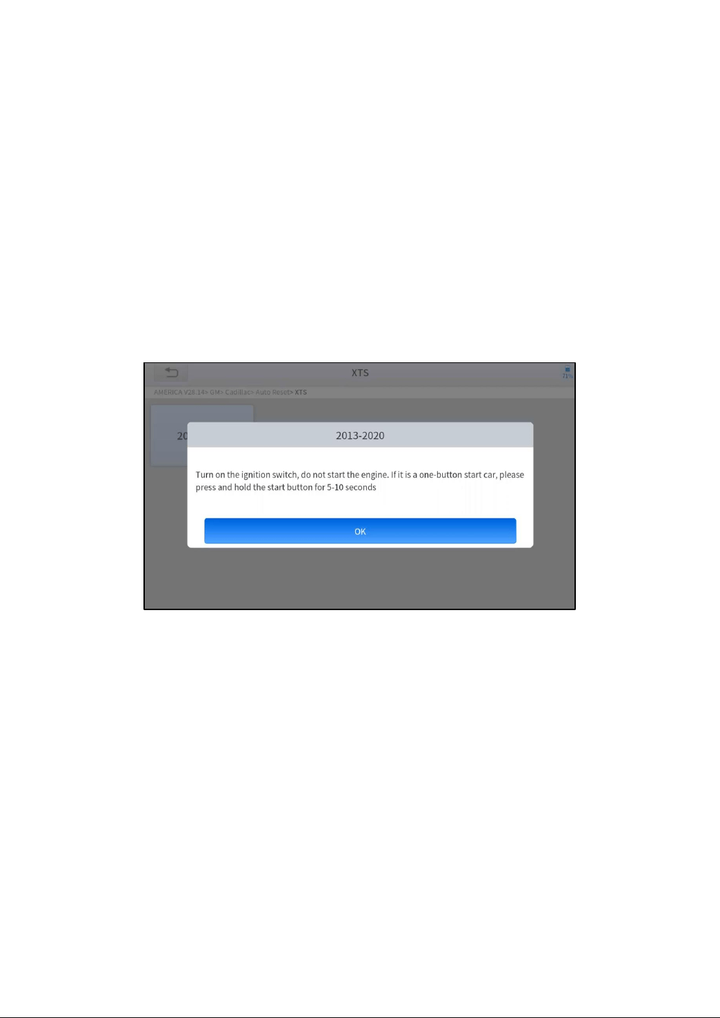
The operation guidelines of the Oil Reset function are shown as below:
1. Enter the Oil Reset menu and choose relevant models according to the vehicle being tested.
2. Follow the instructions displayed that are specific to the vehicle and press OK after completing the instructions
shown.
3. Enter Maintenance mileage reset menu.
25
4. Click INPUT and enter a reasonable value of remaining oil life and press OK.
5. Confirm the [New Value] you just entered, and then click OK at the bottom right to complete the procedure.
6. Message of ‘Write successfully’ displays when Oil Reset function has successfully performed.
26
EPB
Electronic Parking Brake (EPB) System reset is a popular special function. You can use this function to reset the
electronic parking brake system and brake pads (retraction, release of the brake pump), G-sensor and body angle
calibration. This function has multiple uses and can safely and effectively maintain the electronic brake system. These
applications include deactivating and activating brake control systems, assisting in controlling brake fluid, applying and
releasing brake pads, setting brakes after replacing brake discs or brake pads, etc.
1. If the brake pad wears the brake pad sense line, the brake pad sense line will send a signal to the onboard tablet asking
for replacing the brake pad. After replacing the brake pad, you must reset the brake pad to clear the trouble code.
Otherwise, the car continues to falsely notify the user that the brake pads are in need of replacement.
2. A reset must be performed in the following cases:
The brake pad and brake pad wear sensor are replaced.
The brake pad indicator lamp is on.
The brake pad sensor circuit is shorted.
The servo motor is replaced.
The operation guidelines of the EPB function are shown as below:
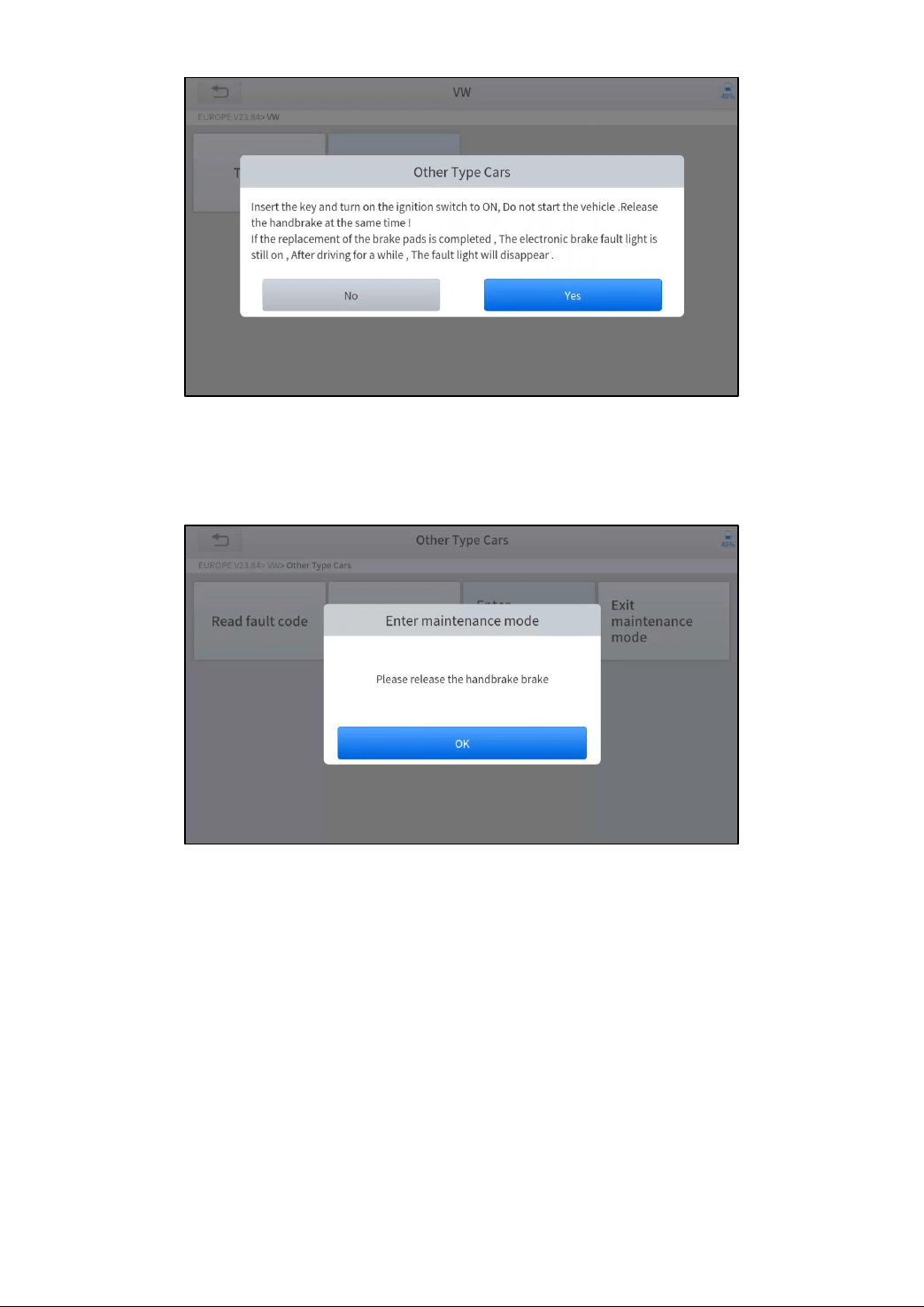
1. Enter the EPB menu and choose relevant models according to the vehicle being tested.
2. Follow the instructions displayed and press YES after completing the instructions shown.
3. Enter the Enter maintenance mode menu and release the handbrake brake. And press OK after completing the
instructions shown.
27
4. Wait until the message of ‘Successful operation’ popes up. And press OK to exit the menu.
5. Enter the Exit maintenance mode menu and wait until the message of ‘‘Successful operation’ popes up.
SAS
Steering Angle Sensors (SAS) System Calibration permanently stores the current steering wheel position as the straight-
ahead position in the SAS EEPROM. Therefore, the front wheels and the steering wheel must be set exactly to the
straight-ahead position before calibration. In addition, the VIN is also read from the instrument cluster and stored
permanently in the SAS EEPROM. On successful completion of calibration, the SAS fault codes will be automatically
cleared.
To reset the steering angle, you need to first find the relative zero point position for the car to drive in a straight line.
Taking this position as a reference, the ECU can calculate the accurate angle for left and right steering.
After replacing the steering angle position sensor, replacing steering mechanical parts (such as steering gearbox, steering
column, end tie rod, steering knuckle), performing four-wheel alignment, or repairing the car body, you must reset the
steering angle.
The operation guidelines of the SAS function are shown as below:
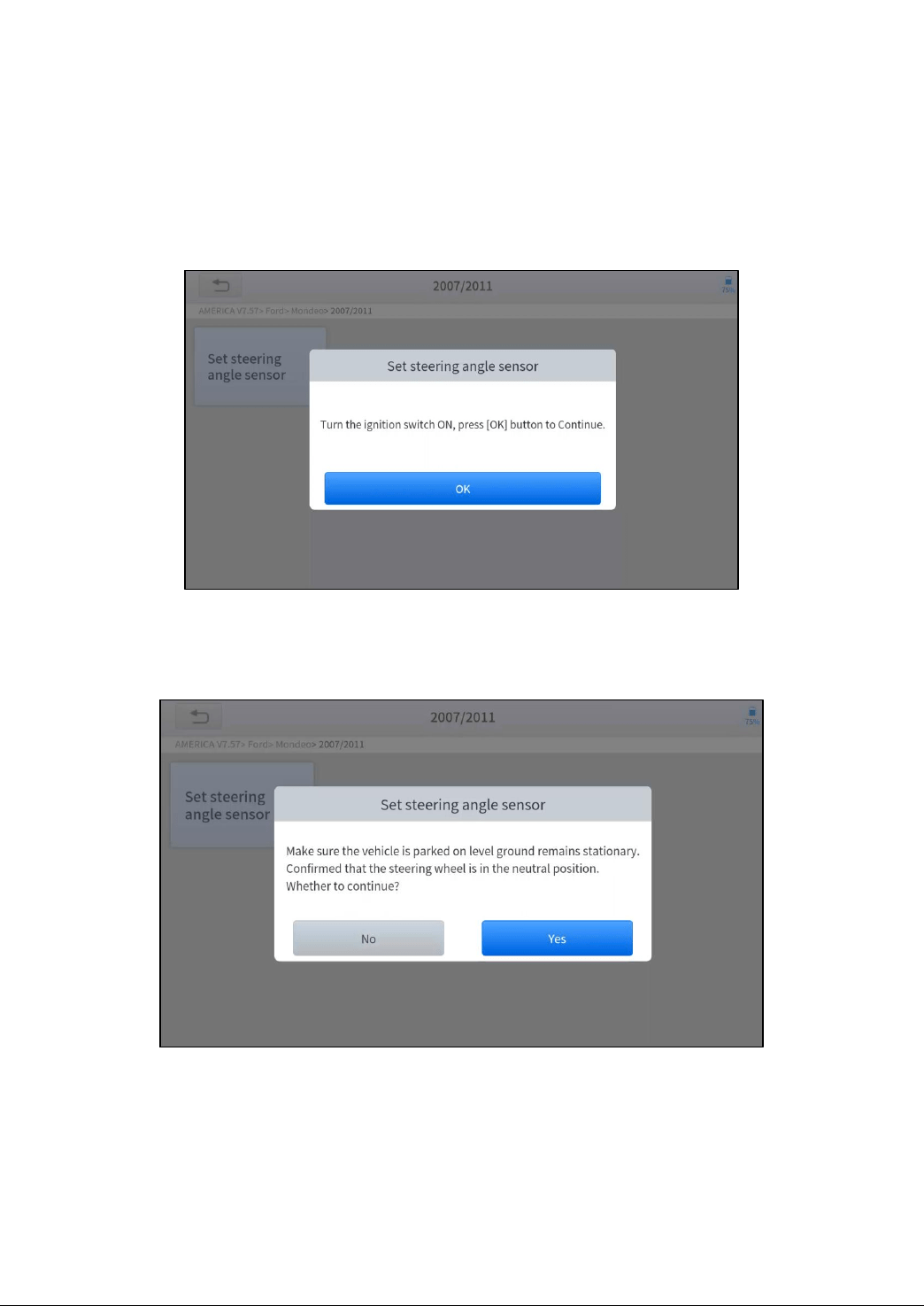
1. Enter the SAS menu and choose relevant models according to the vehicle being tested.
2. Enter the Set steering angle sensor menu and follow the instructions displayed.
3. Wait until the following instruction is displayed and press Yes after completing the instructions shown.
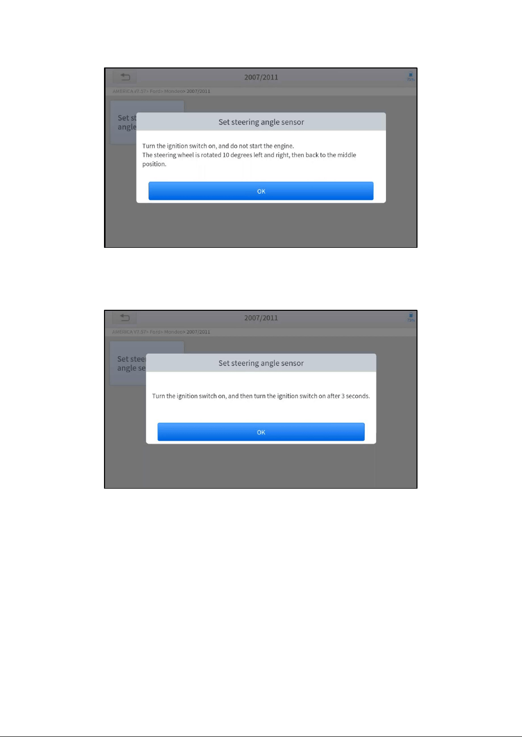
4. Follow the instructions displayed and press OK after completing the instructions shown.
28
5. Wait until the following instruction is displayed and press OK after completing the instructions shown.
1. Message of ‘Function execution is completed’ displayed when SAS reset function has successfully completed.
BMS RESET
The Battery Management System (BMS) allows the scan tool to evaluate the battery charge state, monitor the close-circuit
current, register the battery replacement and activate the rest state of the vehicle.
This function enables you to perform a resetting operation on the monitoring unit of the vehicle battery, in which the
original low battery fault information will be cleared and battery matching will be performed.
Battery matching must be performed in the following cases:
The main battery is replaced. Battery matching must be performed to clear original low battery information and
prevent the related control module from detecting false information. If the related control module detects false
information, it will invalidate some electric auxiliary functions, such as automatic start & stop function, sunroof without
one-key trigger function or power window without automatic function.
Battery matching is performed to re-match the control module and motoring sensor to detect battery power usage
more accurately, which can avoid an error message displayed on the instrument cluster.
The operation guidelines of the BMS Reset function are shown as below:
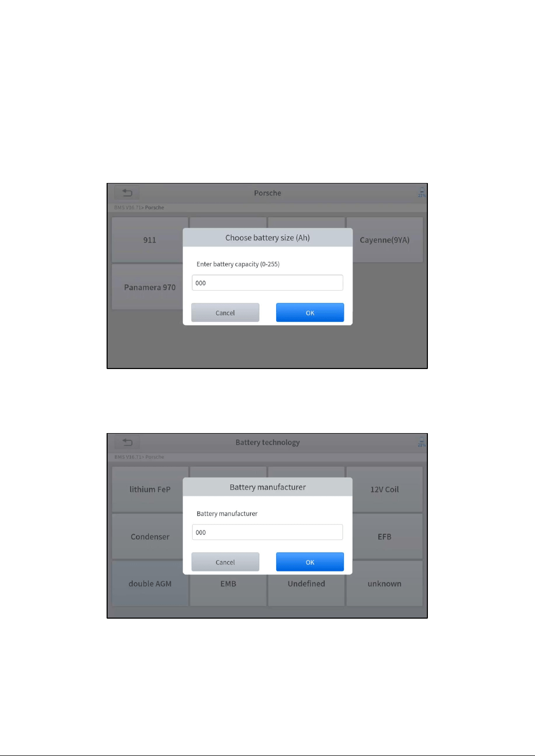
1. Enter the BMS Reset menu and choose relevant models according to the vehicle being tested.
2. Turn on the ignition switch.
3. Press OK to continue the BMS function.
4. Enter battery capacity (within the given range) and press OK after the input.
29
5. Enter the battery manufacturer and press OK after the input.
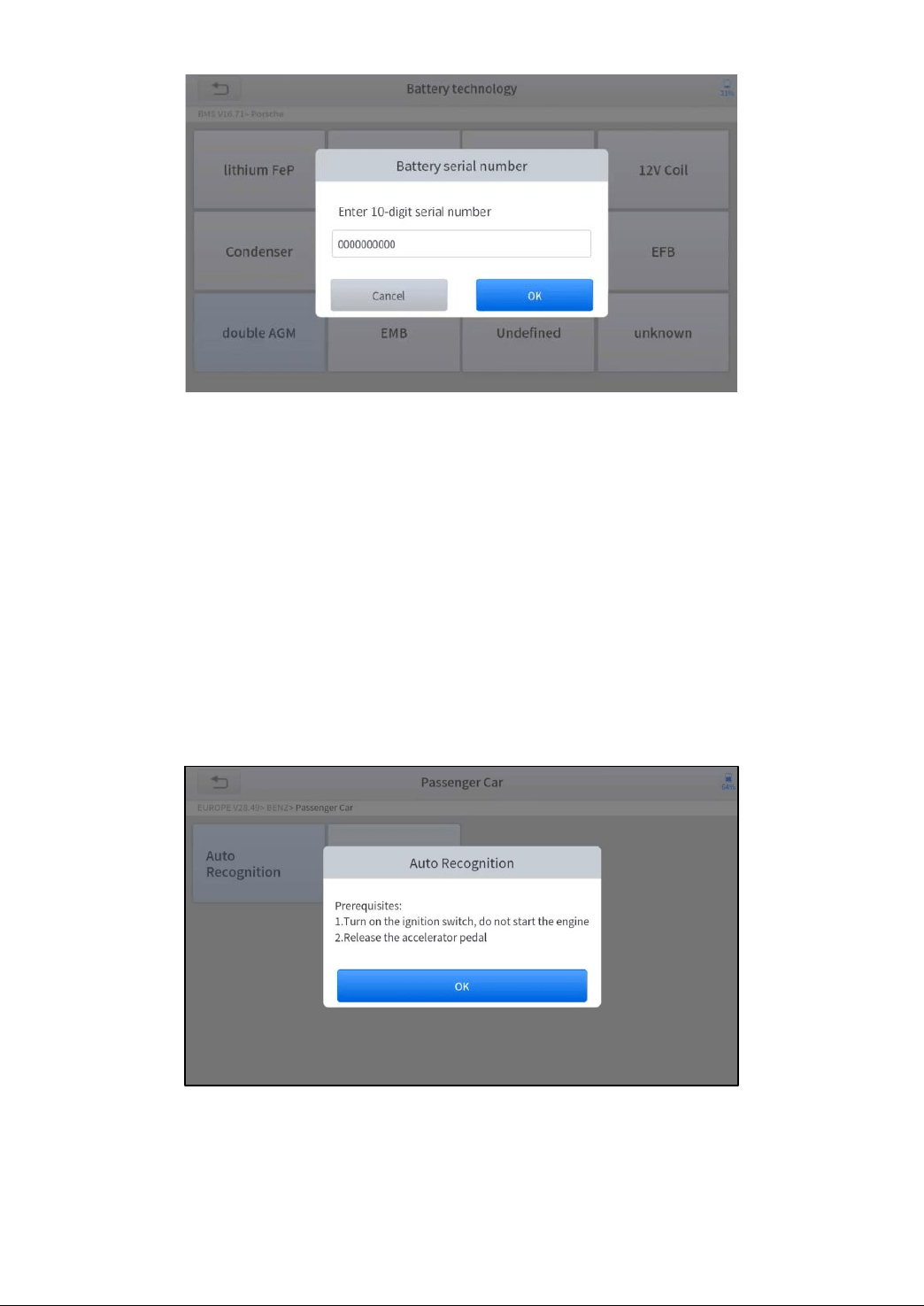
6. Enter the 10-digit battery serial number and press OK after the input.
INJECTOR CODING
This function can write the identification code of the fuel injector into the ECU so that the ECU can recognize the new
injector.
After the ECU or injector is replaced, the injector code of each cylinder must be confirmed or re-coded so that the cylinder
can better identify injectors to accurately control fuel injection.
30
In general cases, there is no need to perform the coding matching function after cleaning;
The identification of the fuel injector includes its working accuracy value and type value. When replacing an injector you need to
find the corresponding model for replacement;
At present, mainstream cars support injector coding functions.
The operation guidelines of the Injector Coding function are shown as below:
1. Enter the Injector coding menu and choose relevant chassis models according to the vehicle being tested.
2. Enter the Fuel injection nozzle injection volume adjustment menu.
3. Read the note displayed carefully and press OK after the reading.
4. Read and confirm the value stored in the cylinders.
5. Enter the Change the value of cylinder menu of the replaced injector(s), enter the new 5-digit value, and then
press OK.
31
Wait until the message ‘Write successfully’ pops up.
6. Turn off the ignition switch.
7. Wait until the message asks you to turn on the ignition switch.
8. Re-enter the Fuel injection nozzle injection volume adjustment menu to check whether the new value(s) are
shown.
DPF REGENERATION
The Diesel Particle Filter (DPF) function manages DPF regeneration, DPF component replacement teach-in, and DPF
teach-in after replacing the ECM.
The ECM monitors driving style and selects a suitable time to employ regeneration. Vehicles driven a lot at idling speed
and low load will attempt to regenerate earlier than vehicles driven more with higher load and speed. For regeneration to
take place, a prolonged high exhaust temperature must be obtained.
In the event of the car being driven in such ways that regeneration is not possible, i.e., frequent short journeys, a
diagnostic trouble code will eventually be registered in addition to the DPF light and “Check Engine” indicators displaying.
A service regeneration can be requested in the workshop using the diagnostic tool.
DPF regeneration is used to clear PM (Particulate Matter) from the DPF filter through continuous combustion oxidation
mode (such as high-temperature heating combustion, fuel additive or catalyst reduce PM ignition combustion) to stabilize
the filter performance.
DPF regeneration may be performed in the following cases:
The exhaust back pressure sensor is replaced.
The PM trap is removed or replaced.
The fuel additive nozzle is removed or replaced.
32
The catalytic oxidizer is removed or replaced.
The DPF regeneration MIL is on and maintenance is performed.
The DPF regeneration control module is replaced.
The operation guidelines of the DPF function are shown as below:
1. Enter the DPF menu and choose relevant models according to the vehicle being tested.
2. Enter the DPF regeneration menu.
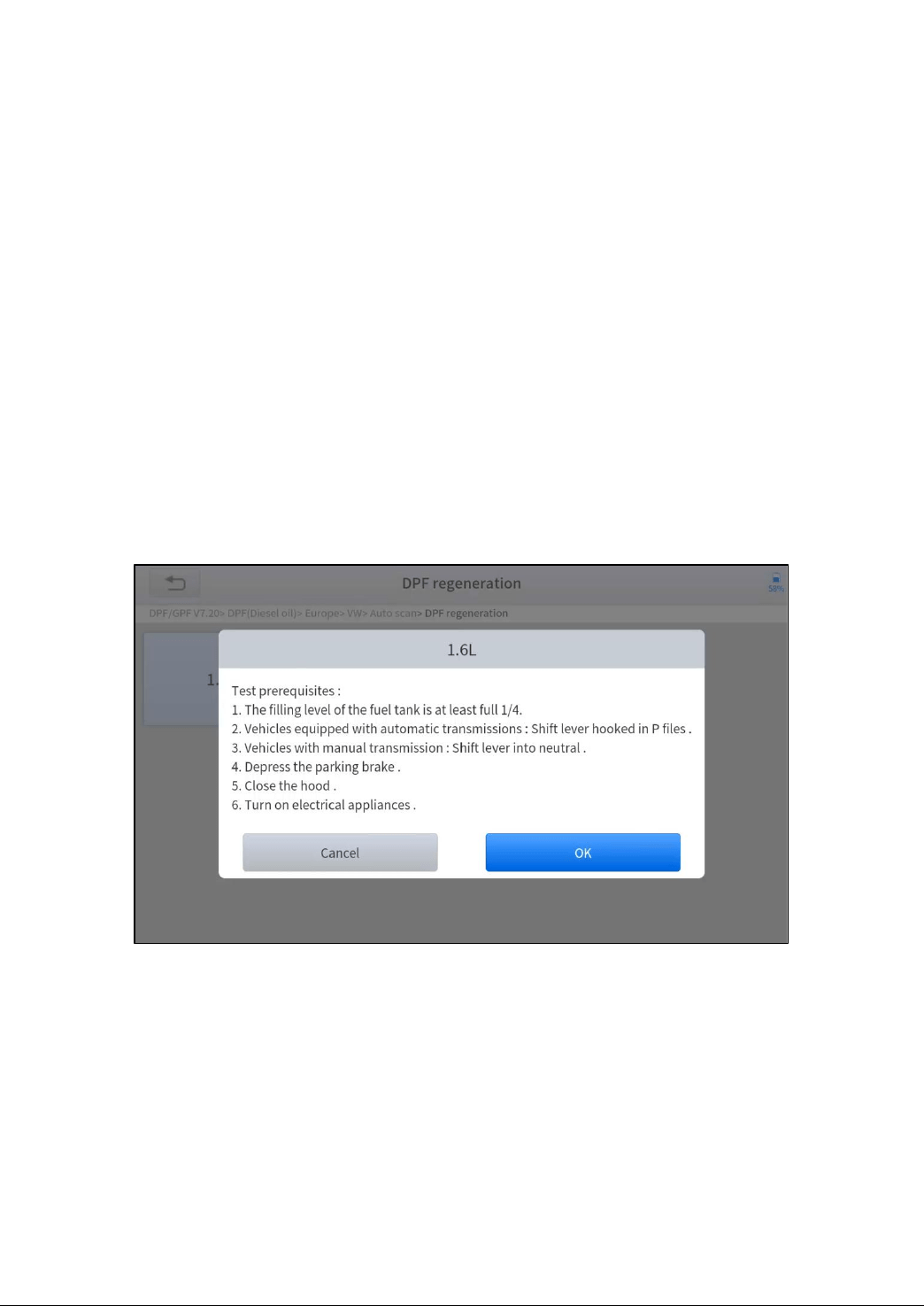
3. Read carefully and complete the requisites listed before performing the DPF regeneration function. Press OK after
completing the instructions shown.
4. Read the fuel tank level and make sure that it fulfills the requirement displayed.
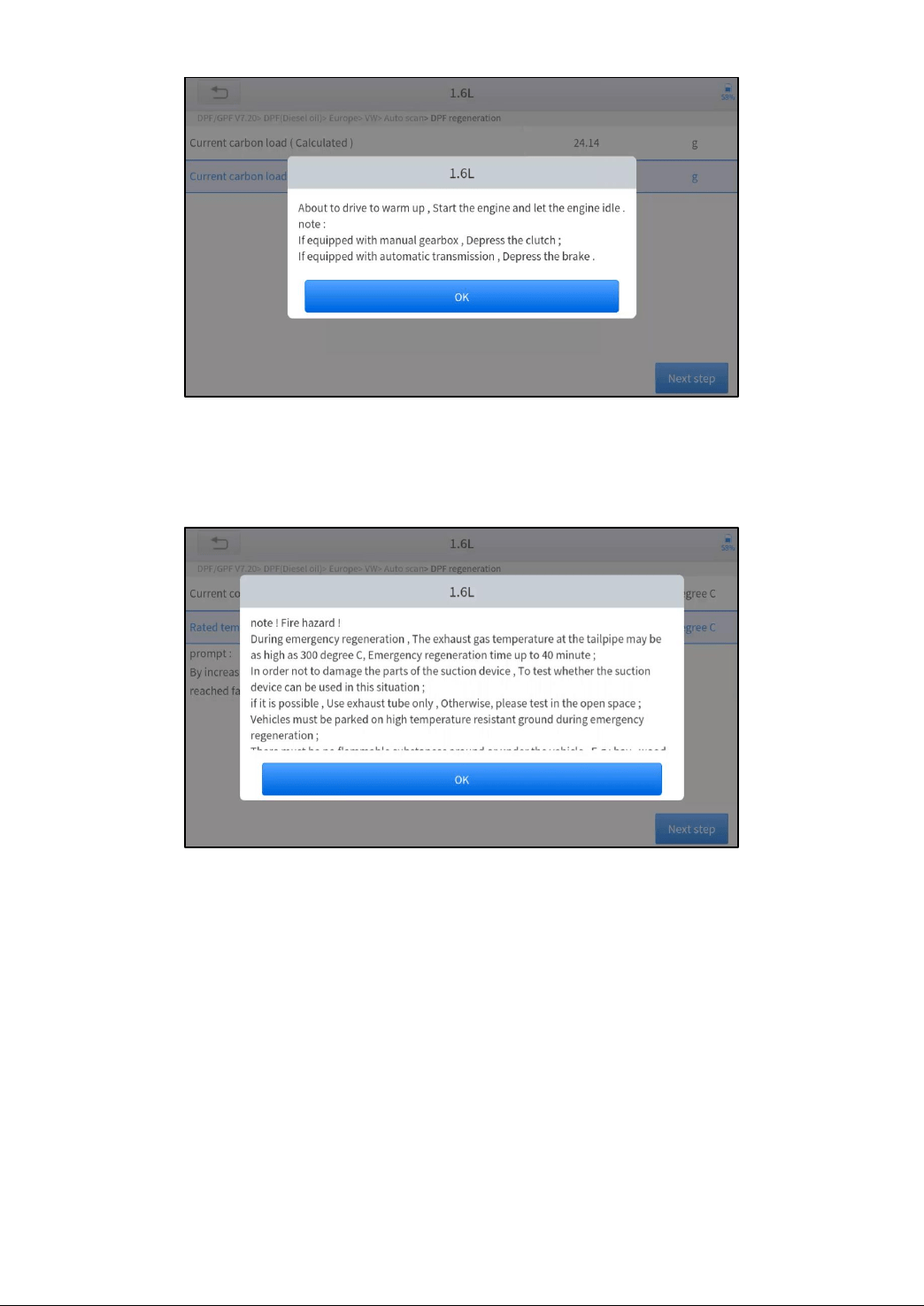
5. Read the carbon deposit load.
6. Choose the “drive to warm up” option and follow the instructions listed below. Press OK after completing the
instructions shown.
7. Read the instructions carefully and follow the instructions shown on the screen. Press OK after completing the
instructions shown.
33
8. Follow the instructions displayed and press OK after completing the instructions shown. IMPORTANT: Please pay
attention to the Note.
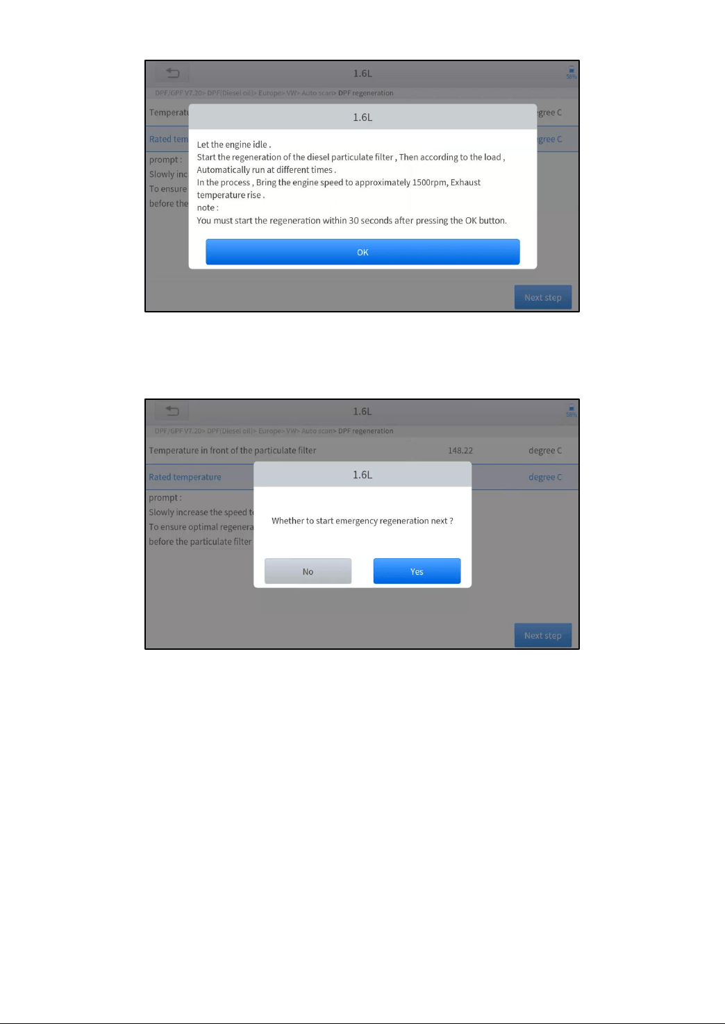
9. Press the OK button to start the regeneration.
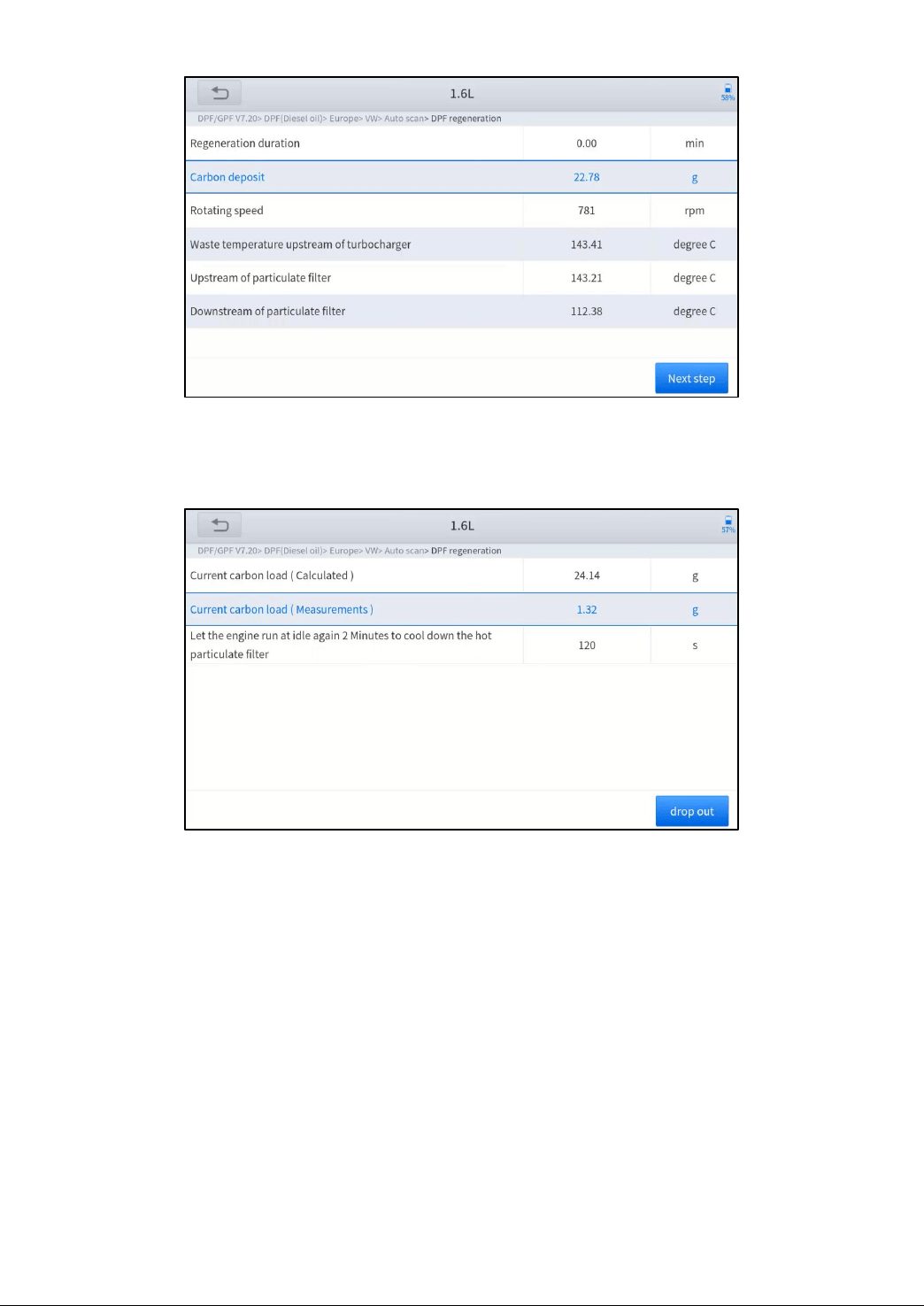
10. Wait for the value of carbon deposit to decrease until a message of ‘Emergency regeneration has been completed’
pops up, this process may take up to 40 minutes.
34
11. Wait for 2 minutes to let the particulate filter cool down.
12. Press drop out to exit the DPF function.
TPMS RESET
This function allows to perform the learning and matching and resetting functions of the tire pressure sensor.
TPMS Reset may be performed in the following cases:
Tire replacement
After troubleshooting tire pressure related problems
Other causes of loss of signal from the tire pressure sensor
1. For tire pressure sensor matching, some vehicle models may need the TPMS activation tool;
2. After learning process, you may need to run the car for some while before the fault light goes off;
3. Tire pressure imbalance may also cause the tire pressure light;
4. This function is only available for activated tire pressure sensors. If you have a brand-new sensor, please use the professional
tire pressure device.
Even for the same model, its tire pressure system may differ by the region where it is manufactured. Therefore, under the
TPMS Reset function, we provide 6 menus for the major automotive manufacturing regions, including Korea, Japan, USA,
China, Australia and Europe, as shown below.

35
And then please enter the sub-menu by the origin region of car make and select the vehicle model you need
TPMS reset can be further divided into 4 methods, such as Automatic Relearn, Static Relearn, Copy ID and OBD
Relearn, which is depending on the specific model. Also, even if the relearning methods are the same, the learning
procedure may differ.
AUTOMATIC RELEARN
1. Install tire pressure sensor appropriately
2. Adjust all TPMS sensors to the standard value
3. Keep the vehicle at a complete standstill status for more than 20 minutes (with the engine off and power off)
4. Drive at 30-100km/h for more than 15 minutes
5. The vehicle will automatically relearn the value, after that, the tire pressure warning will disappear
6. If the relearn procedure fails, please repeat steps 2-5
STATIC RELEARN
a) Install all tire pressure sensors appropriately
b) Pull up the parking brake
c) Turn the ignition to ON/RUN with the engine off
d) Enter the tire pressure learning mode through the instrument panel on vehicle. There will be the corresponding
prompt, which are differ from different car make and model, please subject to the vehicle manual or consult a
professional)
e) Starting from the left front wheel (some models flash the turn signal at the corresponding position), use the TPMS
Activation Tool to activate the sensor, and the vehicle will sound the horn or flash the turn signal at the corresponding
position after successful activation.
! Note: The first sensor should be learned within 2 minutes, otherwise please repeat step 4
f) After the left front wheel sensor is successfully relearned. For the remaining, please activate the remaining tire
pressure sensors in the order of right front, right rear and left rear. The prompt and activation success status are the
same as step 5
36
! Note: The remaining sensor learning needs to be completed within 3 minutes, otherwise please repeat the
relearn procedure from step 4!
g) Turn the vehicle off and power off. Adjust all sensors to the standard value.
h) Tire pressure warning light will disappear after success. If procedure fails, please repeat steps 4-7
OBD RELEARN
1. A TPMS Activation Tool is needed
2. Install tire pressure sensor appropriately
3. Adjust all TPMS sensors to the standard value
4. Activate all sensors in the order of left front, right front, right rear, left rear
5. Connect TPMS Activation Tool to the OBD port of vehicle and perform the OBD relearn function to write the sensor
ID
6. Turn the ignition to ON/RUN, re-trigger all sensors in the order of left front, right front, right rear, left rear
7. Keep the vehicle powered off for more than 25 minutes
8. Drive at 30-100km/h for more than 15 minutes. If relearn successful, the tire pressure warning light will go off.
Otherwise, please repeat steps 4-7
COPY ID RELEARN
! Note: This learning method of the vehicle can only copy ID to the new sensor through the following three
methods to replace the original sensor, if the new sensor cannot change its own ID, then the sensor can only be
replaced by the OEM equipment!
Method 1:
1. Use a TPMS Activation Tool to activate the original sensor, copy the sensor ID to the tire pressure activation device
2. And then program the copied ID into the new sensor through the TPMS Activation Tool (The binary of ID format
should be the same as the original sensor)
3. Remove the original sensor that has been just copied the ID, install the new sensor that has just been programmed,
and put the tire back on
Method 2:
1. Use the TPMS Activation Tool to connect the vehicle OBD port, enter the tire pressure system, copy the ID of the
sensor to be replaced
2. And then program the copied ID into the new sensor through the TPMS Activation Tool (The binary of ID format
should be the same as the original sensor)
3. Remove the original sensor that has been just copied the ID, install the new sensor that has just been programmed,
and put the tire back on
Method 3:
1. Remove the original sensor
2. Use the TPMS Activation Tool to copy the original sensor ID into the new sensor manually (The binary of ID format
should be the same as the original sensor)
3. Install the new sensor to the tire correctly, set the tire pressure to the standard value, and put the tire back on the
vehicle
! Note
a) Tire pressure standard is usually displayed in these places:
Vehicle owner's manual
Label next to the driver's door (near the B-pillar)
Drawer next to the driver's seat of the vehicle
Fuel tank cap
b) This Scan Tool is not a replacement for the TPMS activation tool, and it only provide TPMS Reset/Relearn
function but activation of TPMS sensors. If you need a professional TPMS activation tool, please consult your
local dealer.
37
7. REPORT
Diagnostic Report is used for viewing and printing the saved files, such as Live Data, Trouble codes or pictures generated
in the process of diagnosis. Users also can view a record of which cars have been previously tested. It includes 3 parts:
Diagnosis Report
Data Playback
File Manager
Report
This feature provides a history of diagnostic reports, where you can view and delete the vehicle's diagnostic reports
according to your needs.
When you finish the diagnostics progress and exit the diagnostic application specific to this vehicle, you will get a prompt
of report regeneration.
You can edit the vehicle information, including model year, VIN and mileage units (Mile/Km).
38
When you open the report, located in the header of the table is the workshop information you filled in advance in the
system setup, then the information of the vehicle, as shown below:
Note:
The vehicle information is allowed to edit by clicking the pen icon on the right side of the picture shown above.
You also can click "Print PDF Report" at the bottom right corner to output the pdf report. If you need to close the report
tap on the button “Exit”.
Please follow the below steps to print your report▼
39
Step 1: Install an APP that can connect to your target printer. Add the printer and input the IP address of the printer in the
⚠ The Scan tool doesn’t provide the printer driver software, please install a third part App on the tablet if you need the print
your Diagnostic report.
Step 2: On the Android main menu, go to Settings -> Printing-> Turn printer on.
Step 3: Report-> Choose report-> Print PDF Report-> Print
Step 4: Click the top-left corner of the screen and choose the printer previously added. Then click the button on the right to
print.
REPLAY
This function allows you to replay the living data recorded during the Diagnostic process.
Before replaying the living data, please make sure you have recorded the live data during the Diagnostic
40
FILE MANAGER
This function allows you to check and delete files on the device. Please use this function under the guidance of
professionals. Ordinary users are not recommended to use it by themselves, as it may cause the removal of software or
malfunctioning of the scan tool.
DATA VIEW
You can compare and view the selected and exported PID data on this page. The steps are as follows:
Select the PID you need to record, and click the custom button
Select the DATA EXPORT
Click DATA EXPORT again to stop, and as below you can see the path where the data file is stored on your local
device
41
Click OK to save data file
You can save the data as a file name you edit
42
Select the PREVIEW, and you will go to the DATA VIEW page directly. If you need to stay the Live data page, then
you can click the SAVE.
8. UPDATE
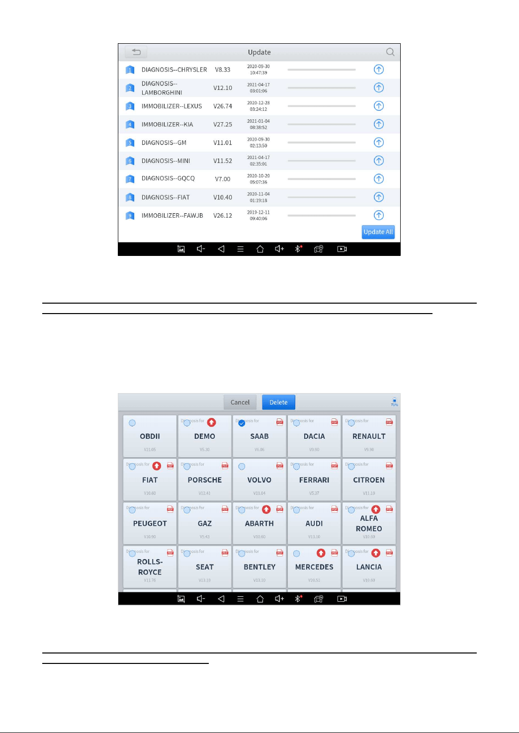
UPDATE SOFTWARE
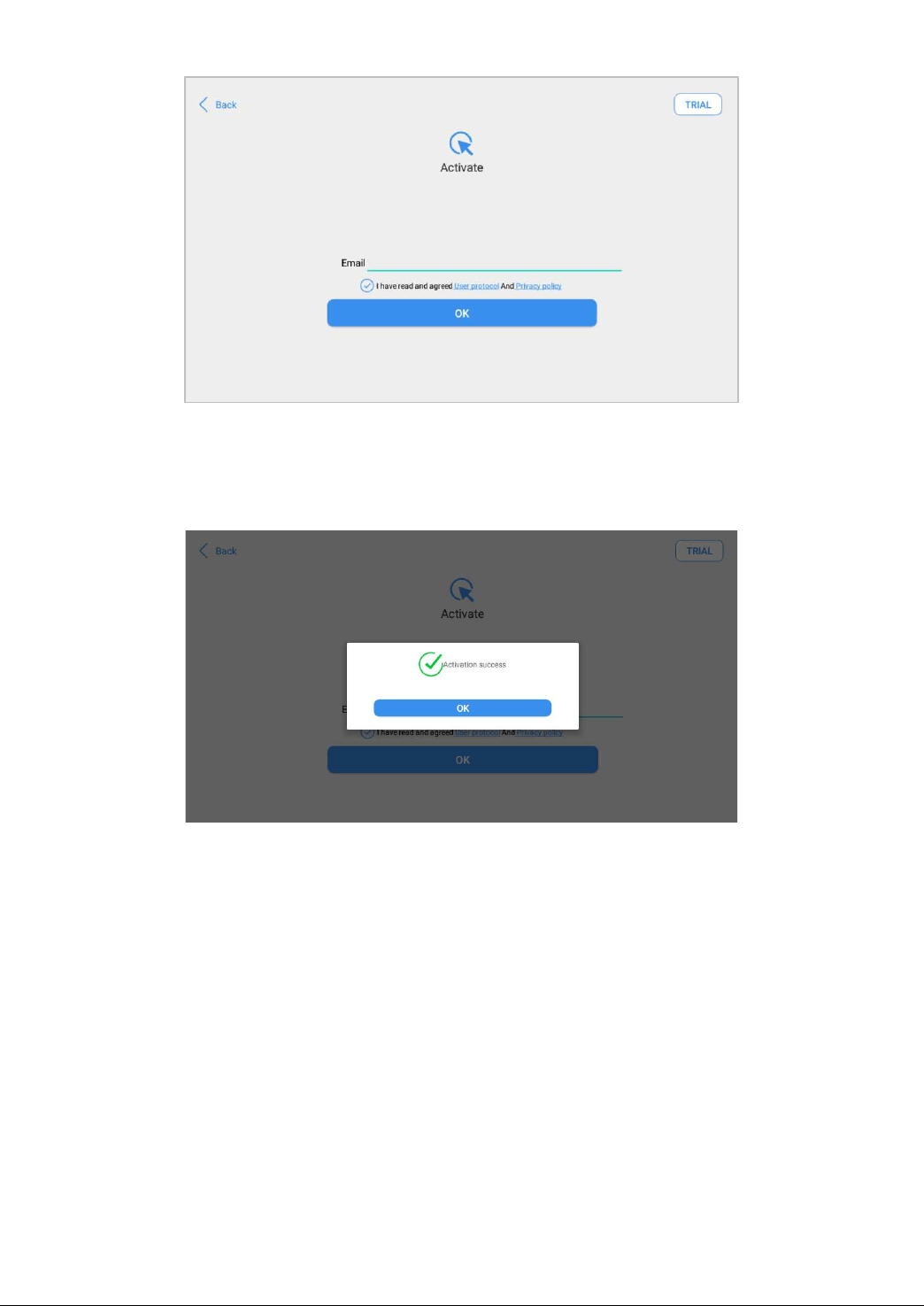
After activating the device, please update the software modules identified in the "Updates" screen. The device will
identify all currently available software packages, and you can download them as needed. ALL software updates directly
via the Internet. To access the update application, open the Diagnostic application and click Updates to enter the screen
shown below:
⚠ After contacting your XTOOL Support to change the language configuration, you need to download all the
software packages on the device again.
Cautions
When the subscription expires, the software has installed on your device itself still is available, but all updates will be
invalid. If you delete specific software due to the personal operation, XTOOL is not responsible for supporting the
restoration of the software when the subscription expires.
To renew your subscription, please contact your local dealer, or contact XTOOL technical support team directly.
43
DELETE SOFTWARE
Long-press the unwanted software until it has been selected, then click the Delete button shown on the upper part of the
screen. And you can select and delete multiple software at once.
9. WARRANTY & SERVICES
Shenzhen XTOOLtech Intelligent Co., LTD.(the Company) warrants to the original retail purchaser of this XTOOL device
that should this product or any part thereof during normal usage and under normal conditions be proven defective in
material or workmanship that results in product failure within ONE YEAR from the date of purchase, such defect(s) will be
repaired, or replaced (with new or rebuilt parts) with Proof of Purchase, at the Company’s option, without charge for parts
or labor directly related to the defect(s).
The Company shall not be liable for any incidental or consequential damages arising from the use, misuse, or mounting of
the device.
This warranty does not apply to:
1) Products subjected to abnormal use or conditions, accident, mishandling, neglect, unauthorized alteration, misuse,
improper installation/repair, or, improper storage;
2) Products whose mechanical serial number or electronic serial number has been removed, altered, or defaced;
3) Damage from exposure to excessive temperature or extreme environmental conditions;
4) Damage resulting from connection to, or use of any accessory or other product not approved or authorized by the
Company;
5) Defects in appearance, cosmetic, decorative, or structural items such as framing and non-operating parts;
6) Products damaged from external causes such as fire, dirt, sand, battery leakage, blown fuse, theft, or improper
usage of any electrical source.
10. REMOTE ASSISTANCE
Tap on "Remote" to start the TeamViewer quick support program, which is a simple, fast, and secure remote-control
screen. You can use this application to enable someone else to use their computer running TeamViewer software to
control your tablet over the Internet. This feature is frequently used by XTOOL's technical support centre when remotely
helping customers with technical support.
44
Computers and mobile devices running TeamViewer are identified by a globally unique ID. When the remote application is
started for the first time, the ID will be automatically generated according to the hardware characteristics and will not be
changed in the future. This TeamViewer ID can individually access all TeamViewer clients.
Before launching the remote desktop application, make sure that the tablet is connected to the Internet so that you can
access the tablet to receive remote support from a third party. If you encounter problems and are not able to solve them,
you could open this application and ask for remote assistance.
1. Turn on the power of the tablet.
2. Click Remote in the Diagnostic application. The TeamViewer screen is displayed, and the device ID will be generated.
3. Your partner must install the remote-control software on their computer by downloading the full version of the
TeamViewer program (http://www.teamviewer.com) online, and then start the software on their computer at the same time,
to provide support and remote control of the tablet.
4. Provide your ID to the partner or XTOOL technician, and then wait for them to send you a remote-control request.
5. A pop-up window will be displayed, asking you to permit the remote-control program to control your device.
6. Click Allow to accept, or click Reject to reject.
45
SHENZHEN XTOOLTECH INTELLIGENT CO., LTD.
Company address: 17&18/F, Building A2, Creativity City, Liuxian Avenue, Nanshan District, Shenzhen, China
Factory address: 2/F, Building 12, Tangtou Third Industrial Zone, Shiyan Street, Baoan District, Shenzhen, China
Service-Hotline: 0086-755-21670995/86267858
Email: m[email protected]
Fax: 0755-83461644
Website: www.Xtooltech.com