Loading ...
Loading ...
Loading ...
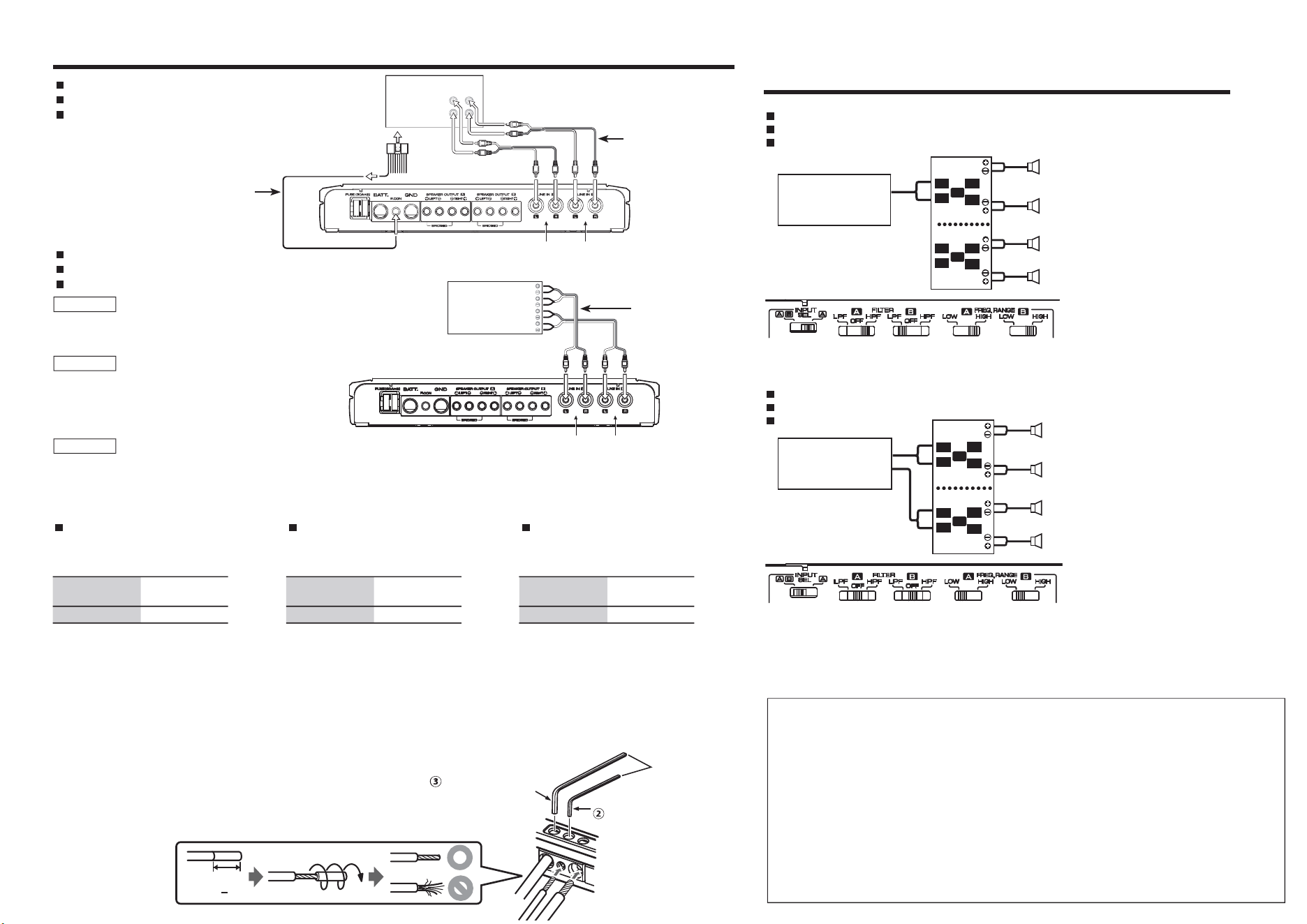
Connection / Raccordements / Conexiones System examples / Exemple de configuration /
Ejemplos del sistema
Bi-amplifer system
Système bi-amplis
Sistema con dos amplificadores
4-channel system
Système 4 voies
Sistema de 4 canales
A.ch B.ch
FACTORY INSTALLED
HEAD UNIT
SPEAKER OUTPUT
L-FRO NT-RL- REAR -R
R
R
L
L
A.ch B.ch
AFTER MARKET
HEAD UNIT
REA R
L
R
FRONT
L
R
R
R
L
L
L
R
RCA INPUT connection
Raccordement RCA INPUT
Conexión RCA INPUT
SPEAKER INPUT connection
Raccordement SPEAKER INPUT
Conexión SPEAKER INPUT
RCA cable
Câble RCA
Cable RCA
Speaker line to male
RCA adapter
Ligne de haut-
parleur à adaptateur
RCA mâle
Línea de altavoz
a adaptador RCA
macho
About the Lead Terminals
1. Wire Thicknesses
You can use wires with the following
thicknesses:
Battery wire and
ground wire
AWG 4 – AWG 6
Speaker wire AWG 8 – AWG 16
2. Strip the wire
Make a cut in the wire sheath (insulator made
from vinyl, etc.) at the position 10–13 mm
(3/8”–1/2”) away from the end of the wire, and
then remove the unnecessary portion of the
sheath by twisting it.
3. Install the wire
Loosen the screw using the supplied hexagon
wrench. Insert the conductor of the wire in the
terminal hole, and then tighten the screw.
À propos des bornes de câble
1. Épaisseurs des câbles
Vous pouvez utiliser des câbles aux épaisseurs
suivantes.
Câble de batterie
et câble de masse
AWG 4 – AWG 6
Câble d'enceinte AWG 8 – AWG 16
2. Dénuder le câble
Coupez la gaine du câble (isolant en vinyle,
etc.) à environ 10–13 mm (3/8”–1/2”) de
l'extrémité du câble, puis enlevez la portion
de gaine inutile en la faisant tourner dans vos
doigts.
3. Installer le câble
Desserrez la vis à l'aide de la clé hexagonale
fournie. Insérez le fil conducteur du câble dans
l'orifice de la borne, puis serrez la vis.
Acerca de los terminales conducto-
res
1. Grosores de cables.
Puede utilizar cables con los siguientes grosores:
Cable de batería
y cable de tierra
AWG 4 – AWG 6
Cable de altavoz AWG 8 – AWG 16
2. Pele el cable.
Realice un corte en el revestimiento del cable
(aislante de vinilo, etc.) a 10–13 mm (3/8”–1/2”)
del extremo del cable y, a continuación, retire la
parte innecesaria del revestimiento torciéndola.
3. Instale el cable.
Afloje el tornillo con la llave hexagonal sumi-
nistrada. Inserte el conductor del cable en el
orificio del terminal y apriete el tornillo.
Hexagon wrench
Clé polygonale
Llave hexagonal
Parts included
Pièces comprises
Partes incluidas
(2.5 mm)
Parts included
Pièces comprises
Partes incluidas
(4.0 mm)
10–13 mm
(3/8
”
1/2
”
)
For U.S.A.
FCC WARNING
This equipment may generate or use radio frequency energy. Changes or modifications to this equipment may cause harm-
ful interference unless the modifications are expressly approved in the instruction manual. The user could lose the authority
to operate this equipment if an unauthorized change or modification is made.
FCC NOTE
This equipment has been tested and found to comply with the limits for a Class B digital device, pursuant to Part 15 of the
FCC Rules. These limits are designed to provide reasonable protection against harmful interference in a residential installa-
tion. This equipment may cause harmful interference to radio communications, if it is not installed and used in accordance
with the instructions. However, there is no guarantee that interference will not occur in a particular installation. If this
equipment does cause harmful interference to radio or television reception, which can be determined by turning the
equipment off and on, the user is encouraged to try to correct the interference by one or more of the following measures:
• Reorient or relocate the receiving antenna.
• Increase the separation between the equipment and receiver.
• Connect the equipment into an outlet on a circuit different from that to which the receiver is connected.
• Consult the dealer or an experienced radio/TV technician for help.
L
R
L
R
L
R
L
R
A
B
HEAD UNIT
Front left speaker
Haut-parleur avant gauche
Altavoz delantero izquierdo
Front right speaker
Haut-parleur avant droit
Altavoz delantero derecho
Rear left speaker
Haut-parleur arrière gauche
Altavoz trasero izquierdo
Rear right speaker
Haut-parleur arrière droit
Altavoz trasero derecho
L
R
L
R
L
R
L
R
A
B
HEAD UNIT
Left speaker (Tweeter)
Haut-parleur gauche (Aigus)
Altavoz izquierdo (Altavoz de agudos)
Right speaker (Tweeter)
Haut-parleur droit (Aigus)
Altavoz derecho (Altavoz de agudos)
Left speaker (Woofer)
Haut-parleur gauche (Basses)
Altavoz izquierdo (Altavoz de graves)
Right speaker (Woofer)
Haut-parleur droit (Basses)
Altavoz derecho (Altavoz de graves)
NOTE
The output from the FACTORY INSTALLED HEAD UNIT up to 50W can be input.
The power is turned on and off as the unit detects input signal (SIGNAL SENSING
TURN-ON). Therefore it is not necessary to connect the power control wire.
REMARQUE
La puissance de sortie maximum de la FACTORY INSTALLED
HEAD UNIT ne doit pas dépasser 50W. L’alimentation est acti-
vée et désactivée lorsque l’appareil détecte le signal d’entrée
(SIGNAL SENSING TURN-ON). C’est pourquoi il n’est pas néces-
saire de connecter le câble de commande de l’alimentation.
NOTA
El FACTORY INSTALLED HEAD UNIT deberá tener una potencia de salida máxima
no superior a 50W. La alimentación se enciende y apaga conforme la unidad
detecte una señal de entrada (SIGNAL SENSING TURN-ON). Por lo tanto no es
necesario conectar el cable de control de alimentación.
Power control wire
Câble de commande de l’alimentation
Cable de control de alimentación
Loading ...
Loading ...
Loading ...