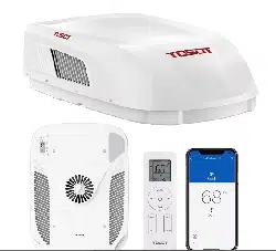

User Manual
RV AIR CONDITIONER
Before installing and using your TOSOT Air Conditioner,
please read this user manual in its entirety.
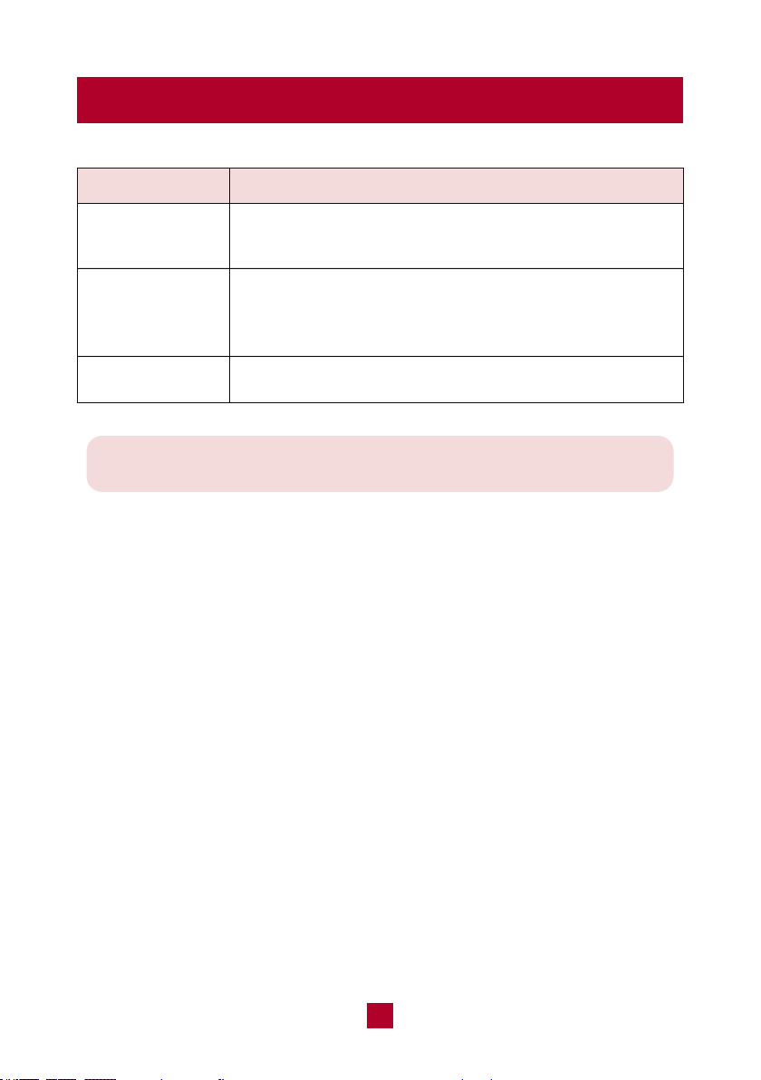
MO DEL NUMBER
Ceiling Assembly Roof Top Unit
GRH15DC-A6NNA1A/I GRH15DC-A6NNA1A/O

Welcome to the TOSOT Direct Family!
We’re extremely happy to welcome you as a new member of our family! Please
read the tips below before using your product for the first time.
1. The RV air conditioner is a heavy object, which needs two or more people to lift
and install. Failure to do so could result in injury or other accidents.
2. Allow the unit to sit upright for at least 3-4 hours before powering on. Shipping
carriers may set the unit on its side, which causes the refrigerant to pool in
certain areas. Standing the unit upright for 3-4 hours allows the refrigerant to
move freely within the coils.
3. Run the unit continuously for 24 hours after installation. This allows the unit to
work out any “kinks” that may have resulted during shipping from our factory to
your doorstep.
4. Some parts with sharp edges may cause injury, so gloves are highly recommended
for unpacking and installing.
5. For a quick start video guide of installation, please contact Customer Support.
6. If you have any problems with your product, please send us an email before
submitting a return request, as there might be a simple solution for your issue.
Tips for First-Time Use

Table of Contents
--------------------------------------------
--------------------------------------------------------------
----------------------------------------------
---------------------------------------
-----------------------------------------
------------------------------------------------------
---------------------------------------------------
--------------------------------------------
---------------------------------------------------
------------------------------------------------------------
-------------------------------------------------------------
----------------------------------------
Safety and Instructions
Installation and Setup
Electrical Safety Warning
Refrigerant Information
Part List
Parts Description
Installation
Operation
Control Panel
Remote Control
Combination Buttons
Cleaning and Maintenance
01
01
02
03
04
06
07
18
18
20
25
------------------------------------------
Replacing the Batteries
26
26
----------------------------------------------------
-------------------------------------------------
Troubleshooting
Malfunction Codes
28
30
-----------------------------------
Warranty & Customer Support
31
--------------------------------------------
-----------------------------------------------
Warranty Information
Customer Support
31
31

Safety and Instructions
01
Installation and Setup
Your safety and the safety of others are very important to us. Please read the
following safety precautions before use and installation. A digital version can be
obtained from customer support.
● Use the appliance only for its intended purpose as described in this manual.
● Do not use electric cords that have become frayed or otherwise damaged.
● This air conditioner must be properly installed in accordance with the Installation
instructions as described in this manual before it is used.
● Please turn off the unit and disconnect all power to the vehicle before cleaning
and servicing.
● When refrigerant leaks or requires discharge during installation, maintenance, or
disassembly, it should be handled by certified professionals or otherwise in
compliance with local laws and regulations.
● The appliance shall be stored in a room without continuously operating ignition
sources. (for example open flames, an operating gas appliance, or an operating
electric heater.)
● Compliance with national gas regulations shall be observed.
● Should repair be necessary, contact your nearest authorized Service Centre. Any
repairs carried out by unqualified personnel may be dangerous.
● Air conditioners covered in this manual are designed for installation on an RV’s roof.
● Installation of this air conditioner must be in accordance with NFPA 1192 and
NFPA 70.

02
Electrical Safety Warning
● All wiring must be complied with local and national electrical codes. All wiring
must be installed by qualified electricians. If you have any questions about the
instructions, contact a qualified electrician.
● Make sure the power supply is cut off you until finish installing the air conditioner.
Otherwise, it may cause an electric shock.
● Check the available power supply and resolve any wiring problems before
installing and operating this unit.
● This air conditioner is designed to operate from a 115V AC, 60Hz, 1 Phase
power supply.
● Air switch should include magnet buckle and heating buckle function to can
protect the circuit from short and overloading.
● An all-pole disconnection switch having a contact separation of at least 3mm in
all poles should be connected in the fixed wiring.
● Electrical wiring may be present between roof and ceiling. Be sure that power is
disconnected at the mains and battery.
FCC Information
However, there is no guarantee that interference will not occur in a particular
installation. If this equipment does cause harmful interference to radio or television
reception, which can be determined by turning the equipment off and on, the user
is encouraged to try to correct the interference by one or more of the following
measures:
This device complies with part 15 of the FCC Rules. Operation is subject to the
condition that this device does not cause harmful interference.
Note:
This equipment has been tested and found to comply with the limits for a Class
B digital device, pursuant to part 15 of the FCC Rules. These limits are designed
to provide reasonable protection against harmful interference in a residential
installation. This equipment generates, uses and can radiate radio frequency
energy and, if not installed and used in accordance with the instructions, may
cause harmful interference to radio communications.

03
● Reorient or relocate the receiving antenna.
● Increase the separation between the equipment and receiver.
● Connect the equipment into an outlet on a circuit different from that to which the
receiver is connected.
● Consult the dealer or an experienced radio/TV technician for help.
● This air conditioner utilizes fluoride R-32 refrigerant, which is a next-generation
refrigerant that efficiently carries heat and has a lower environmental impact than
other refrigerants.
● Compared to other common refrigerants, R32 is a nonpolluting refrigerant with no
harm to the ozone layer of the atmosphere. The influence of the greenhouse effect
is also lower. R32 has very good thermodynamic features which lead to high energy
efficiency. The units, therefore, need less filling and maintenance.
● The refrigerant is flammable and odorless. Furthermore, it can lead to explosions
under certain conditions. However, the flammability of the refrigerant is very low
and can only be ignited by fire.
● The appliance should be stored in a room without continuously operating ignition
sources, for example, open flames, an operating gas appliance, or an operating
electric heater.
● Ducts connected to an appliance should not contain an ignition source.
● Keep any required ventilation openings clear of obstructions.
● Do not pierce or burn the appliance or any of its components.
● Be aware that refrigerants may not contain an odor in the presence of a leak.
● Do not use means to accelerate the defrosting process or to clean, other than
those recommended by the manufacturer.
● Servicing shall be performed only as recommended by the manufacturer.
Appliance filled with flammable gas R32.
A2L
Refrigerant Information
04
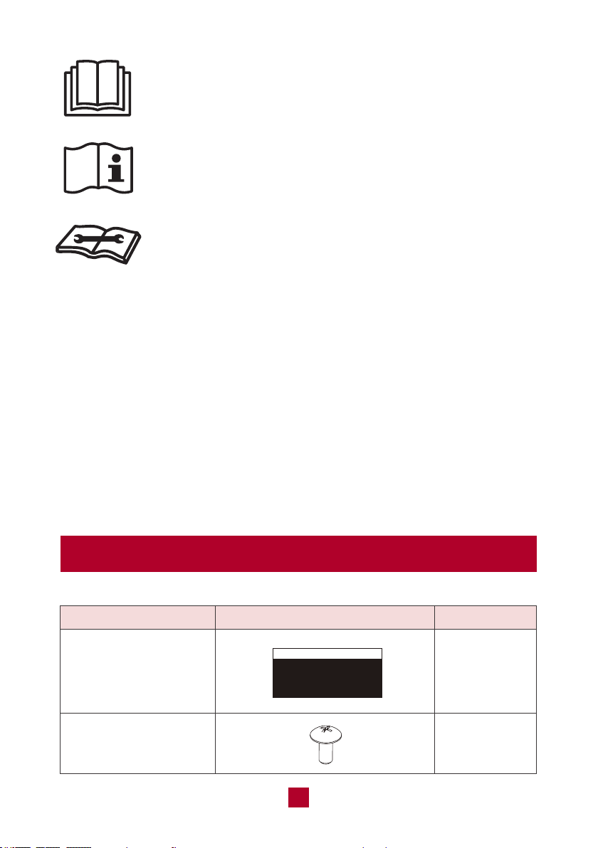
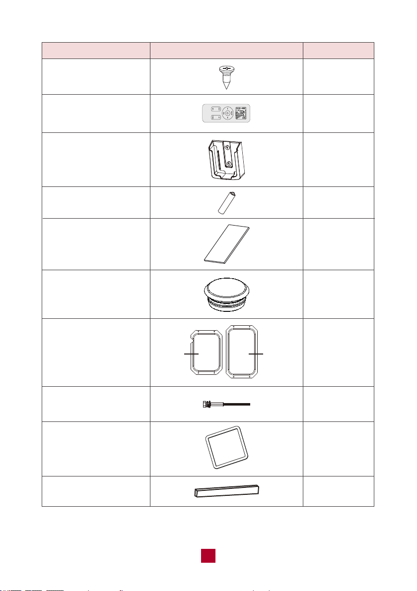
Parts List
Fabric duct
PART
LOOKS LIKE
QUANTITY
2
Before using the appliance, read the owner's manual first.
Before using the appliance, read the owner's manual first.
Before using the appliance, read the owner's manual first.
Recommended Operating Environment
● The recommended operating temperature range is 23°F-115°F (-5°C-46°C).
(Heating:23°F-75°F (-5°C-24°C ) /Cooling:64°F-115°F (18-46°C).
● The outdoor unit may stop operation due to various kinds of protection within the
working temperature range.
● Air inlet should be far away from obstacles and not have any objects near the air
outlet. Otherwise, it will affect the radiation of the heat-removal pipe.
● Please try your best to keep far away from fluorescent lamp.
● The appliance shall not be installed in laundry areas.
Tapping screw for
duct plate
8
05
Remote control holder
Double-sided tape
AAA battery
PART
LOOKS LIKE
Fixing screw for
remoter control holder
Remote control
Screw cap
Gasket
Sponge (sealing strip)
Duct plate
Bolt for ceiling
assembly (5.3 inch)
QUANTITY
2
1
1
2
1
6
1 set
4
1
1
use in
indoor
(bottom)
use in
outdoor
(upper)
06
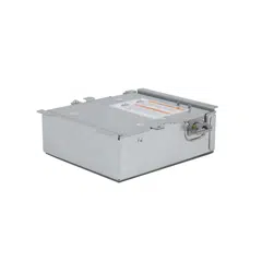
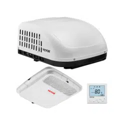
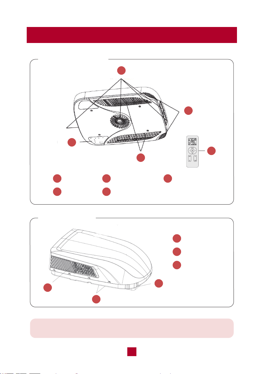
Parts Description
Ceiling Assembly
Roof Top Unit
Note: This is a universal introduction for a variety of models. The display
content may be different from the actual. Please refer to the actual unit.
1
Air Outlet
2
Filter Sub-assy
4
Air Inlet
5
Remote Control
3
Control Panel
2
1
3
4
5
1
Air Inlet
2
Drainage Outlet
3
Chassis
2
1
3

07
Installation
Warning
● The air conditioner has been designed for use in recreational vehicles.
● Be careful when testing the unit. Do not operate the unit with the exterior case
removed.
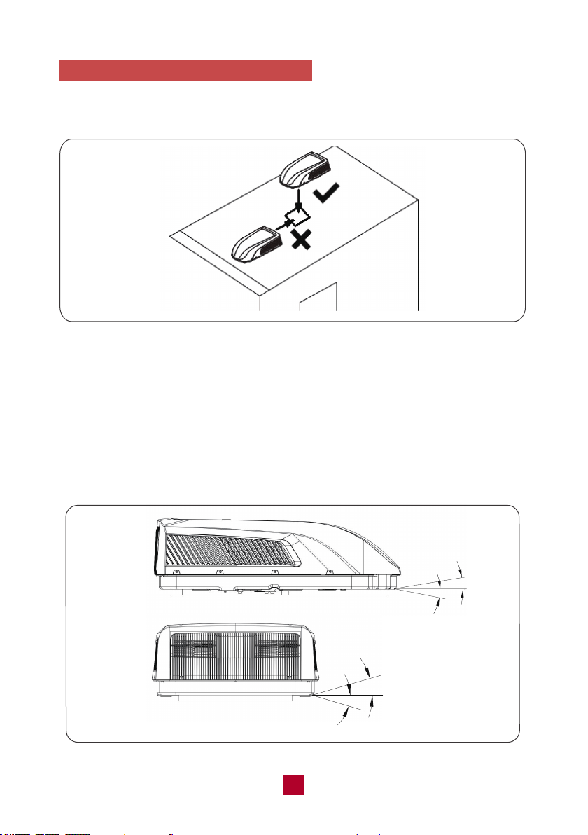
● Outdoor unit can't be installed at the low recess of the roof of the vehicle. It must
be mounted on the flat surface of the roof to make sure rain, car-washwater,
condensated water, etc. can be drained smoothly. No water is allowed to be
accumulated around the outdoor unit. Otherwise, it will cause malfunction or
safety hazards as the water will pour into the air conditioner.
● There must be 1.2 to 5.32 inches between the RV ceiling and roof.
Required Tools
1. Screwdriver
2. Electric Drill with 1/8” drill bit
3. Bubble Level
4. Pencil
5. Torque Wrench (0-60 in-lbs)
6. Ruler
7. Scissors

08
CASE A
If a roof vent is already present in the desired mounting location for the air
conditioner, you may follow the steps below:
● Remove all screws which secured the roof vent to the vehicle. Remove the
vent and any additional trim. Carefully remove all chalking around the opening
area to make the surface clean.
● It may be necessary to seal some of the previous roof vent mounting screw
holes which are not covered by the air conditioner chassis gasket.
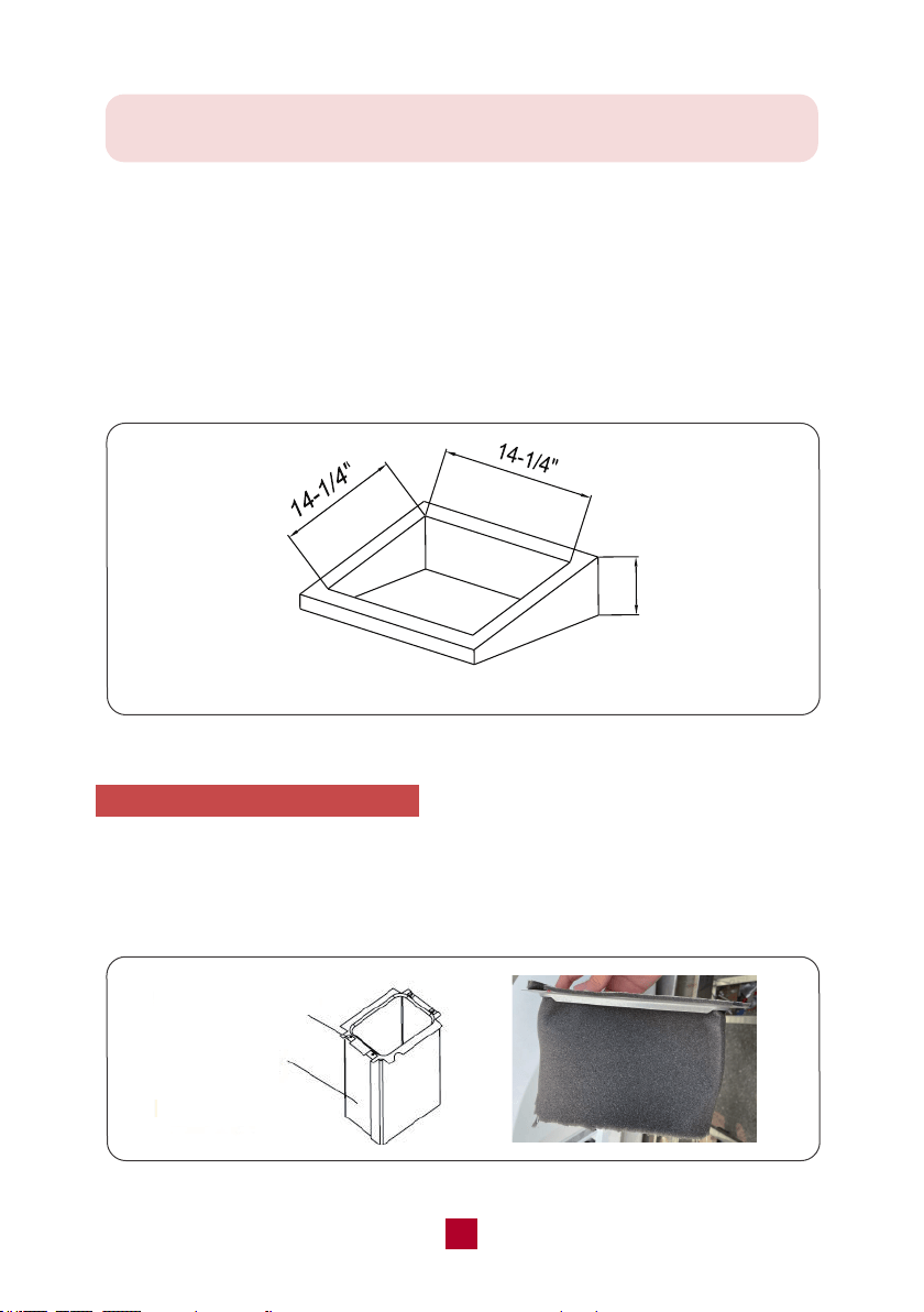
● Examine the roof opening size. If the opening is smaller than 14-1/4” x 14-1/4”,
the opening must be enlarged.
Installation
1. Select an Installation Site
● Check the roof of the vehicle to determine whether it can support both the rooftop
unit and the ceiling assembly without additional support.
● Choose an area where the installation of an indoor unit will not interfere with
existing structures.
● Check the roof of the vehicle to that there must be 1.2 to 5.32 inches between the
RV ceiling and roof.
● A vent hole (14-1/4” x 14-1/4”) is needed once the location for your air conditioner
has been determined. You may use existing vent holes referring to CASE A below,
or you need to cut a new hole referring to CASE B below.
09
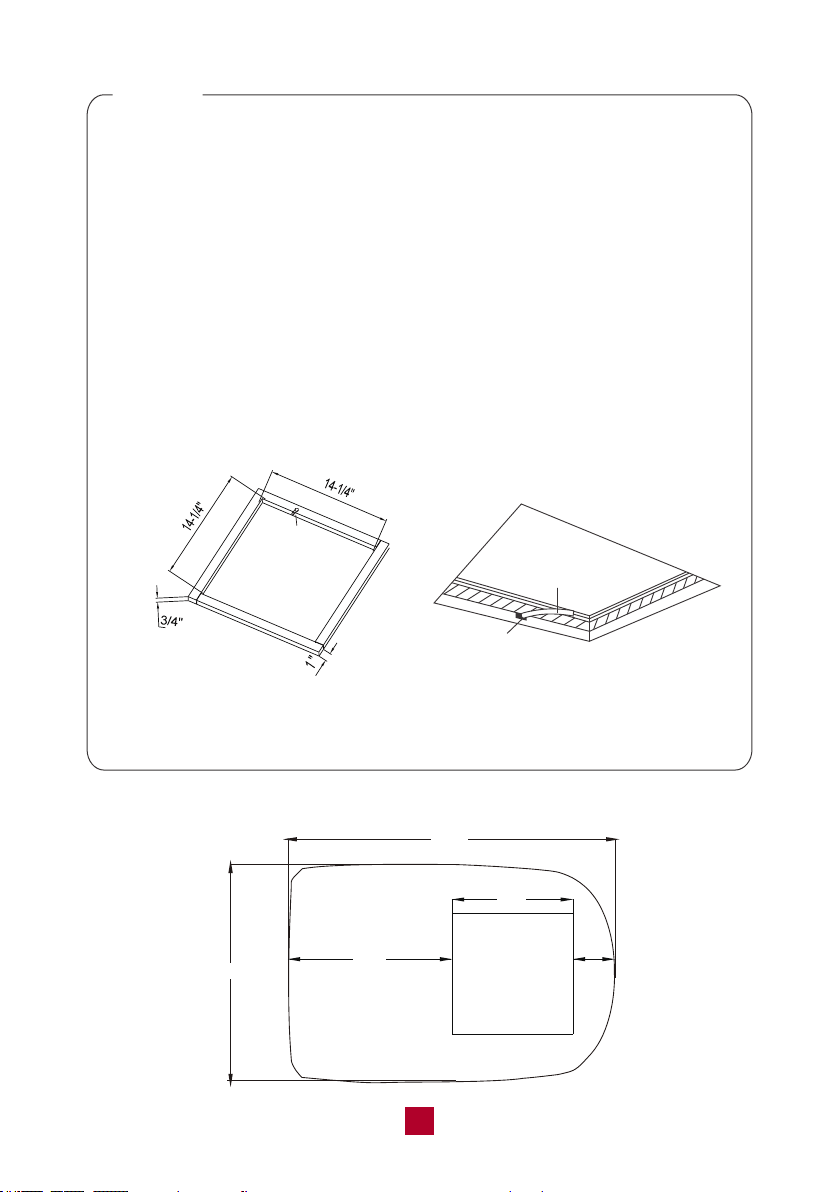
Hole for
Wires
Figure 1
Hole
Wires
CASE B
If there is no existing roof vent opening, a new opening (14-1/4” x 14-1/4”, see
Figure 1) is required to be cut in the vehicle roof and the interior vehicle ceiling.
● Make sure the ceiling opening edge is smooth to avoid snags.
● If the roof is not strong enough to support the machine, a support structure
must be placed between the exterior rooftop and interior ceiling. The reinforced
framed structure must follow the following guidelines:
1. It must be capable of supporting both the weight of the rooftop air conditioner
and the interior ceiling assembly.
2. It must be capable of holding the roof’s outer surface and interior ceiling apart
and supporting them so that when the outdoor and indoor unit are bolted
together, no collapsing occurs. A referencing support frame is shown in
Figure 1. The thickness of the frame should be 3/4” in minimum.
3. A hole through the frame for the power supply wiring is needed. Route the
supply wiring (not included) through the frame at the same time the support
frame is being installed.
Roof Top Unit Dimension Note
42.4”
(24”)
28.3”
14-1/4”
4.2”
(14-1/4”)x(14-1/4”)
OPENING
10
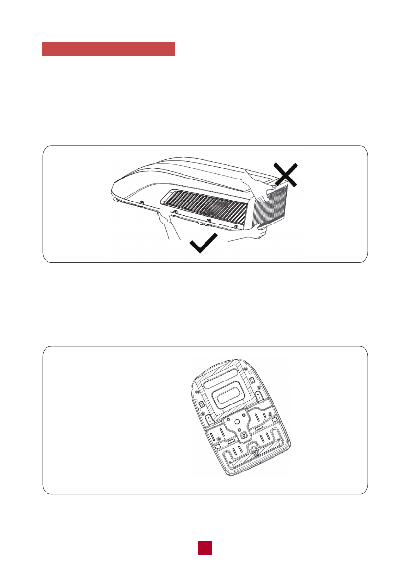
2. Stick Gasket and Sponge
● After the mounting hole area is properly prepared, open the package and remove
the carton and shipping pads from around the rooftop air conditioner.
● Carefully lift the outdoor unit with the package on top of the vehicle. Do not use
the outer plastic shroud for lifting. Do not lift by the air outlet grille at the back of
the outer case (see Figure 2).
● Take out 1 gasket and 1 sponge (sealing strip).
● Clean up any debris at the sticking position of the chassis (as shown in Figure 3)
on the outdoor unit to ensure that the sticking position is clean.
Figure 2
Figure 3
Sticking Position of Gasket
Sticking Position
of Sponge (Sealing Strip)
11
Level
Level
Level
Level
Figure 5
Front
● Center the rooftop air conditioner over the prepared cutting hole, making sure the
gasket is attached to the edge of the mounting hole.
● The front section of the outdoor unit of the air conditioner must be in the same
direction as the vehicle, which is useful for reducing wind resistance.
● Please make sure the rooftop air conditioner is mounted on a level plane from
front to rear and side to side. Figure 5 shows the maximum allowable degrees
that the unit can be mounted above or below level.
3. Install and mount the Roof Top Unit
● Lift the outdoor unit and then place the outdoor unit in the roof of the vehicle. Do
not drag the outdoor unit. Otherwise, the seal may fall off (see Figure 4).
Figure 4
12
Note: The unit can only operate for a short time at the maximum sloping
angle of 5° for preventing water leakage.
● If the roof of the vehicle is sloped (not level) such that the rooftop air conditioner
cannot be mounted within the maximum allowable degree specifications, an
exterior leveling shim will need to be added to make the unit level. A referencing
leveling shim is shown in Figure 6.
● Once the rooftop air conditioner has been leveled, some additional shimming may
be required above the interior ceiling assembly. The rooftop air conditioner and the
ceiling assembly must be parallel with each other before they are secured together.
4. Install the Ceiling Assembly
● Carefully take the ceiling assembly out of the carton and remove the ceiling grille.
● Remove the sticker on the fabric duct and assemble it to the flat side of the upper
duct plate. Then turn over the duct to make the black side out.
Figure 6
Height Varies to Make Unit Level
Upper Duct Plate
Fabric Duct
(black side out)
Figure 7
Fabric Duct
(black side out)
13
Warm tips:
please make sure you didn't shorten the length of fabric duct in this step.
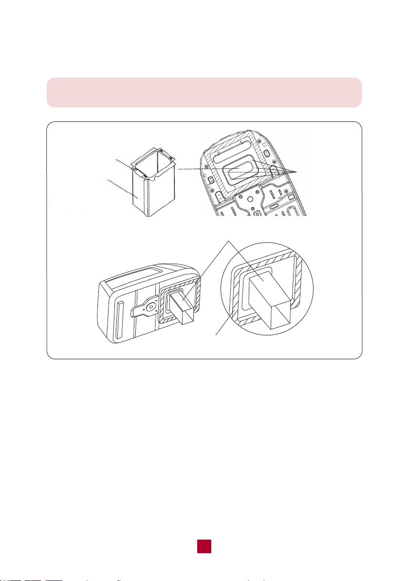
● Fasten the fabric duct (assembled) to the chassis of the rooftop air conditioner
with 4 tapping screws by the upper duct plate. See Figure 8.
from 2.3-2.5Nm (see Figure 9). Please start threading the mounting bolts by hand
to avoid cross-threading. DO NOT START THE MOUNTING BOLTS WITH AN AIR
GUN. The mounting bolts should be tightened until the chassis gasket has been
● Before lifting the ceiling assembly, pull the fabric duct so it hangs out of the way
and does not get caught under the ceiling assembly frame.
● Check the thickness of your roof. If the roof is 1.2-3.15 inch thick, please use the
5.3" bolts. If the roof is 3.15-5.32 inch thick, please use a 7.5" bolts (not included ).
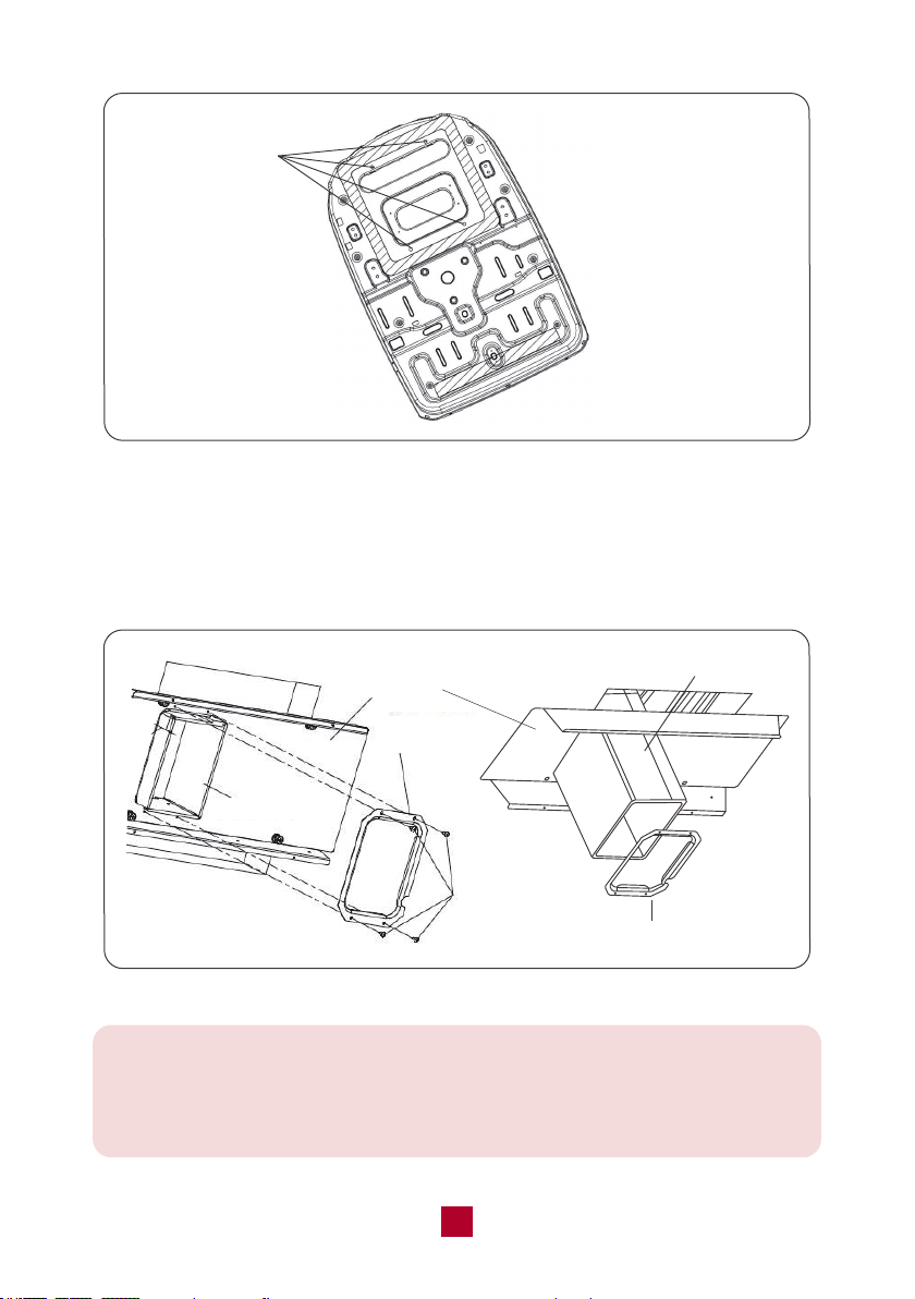
● Set the fabric duct into the duct opening of the frame. Secure the ceiling assembly
plate to the rooftop air conditioner with the mounting bolts with maximum torque
evenly compressed.
4 Holes for
Tapping Screw
Upper Duct Plate
Fabric Duct
Fabric Duct
Upper Duct Plate
Figure 8
14
Bottom Duct
Plate
Fabric Duct
4 Screws
● Secure the bottom duct plate to the ceiling assembly frame with 4 tapping screws
(see Figure 10) and fasten each side of the fabric duct. After the securing, there
might leave some spare fabric that may extend beyond the edge of the bottom
duct plate need to be cut.
Figure 9
Figure 10
Bottom Duct Plate
Fabric Duct
4 Bolts for
Ceiling Assembly
Frame Fixing
Frame
Warm tips:
If the fabric duct is too long to install (original length: 11.8 inches), you could
shorten the fabric duct for easier installation. But please make sure it would not
be over-cut to be too short to install the bottom duct plate.
15
5. Electric Wiring
Warning:
Make sure that all power supply to the unit is disconnected before performing
any work on the unit to avoid the possibility of shock or injury and damage to
the equipment.
After the interior ceiling assembly frame is properly secured to the rooftop air
conditioner, you can start on the electrical connections.
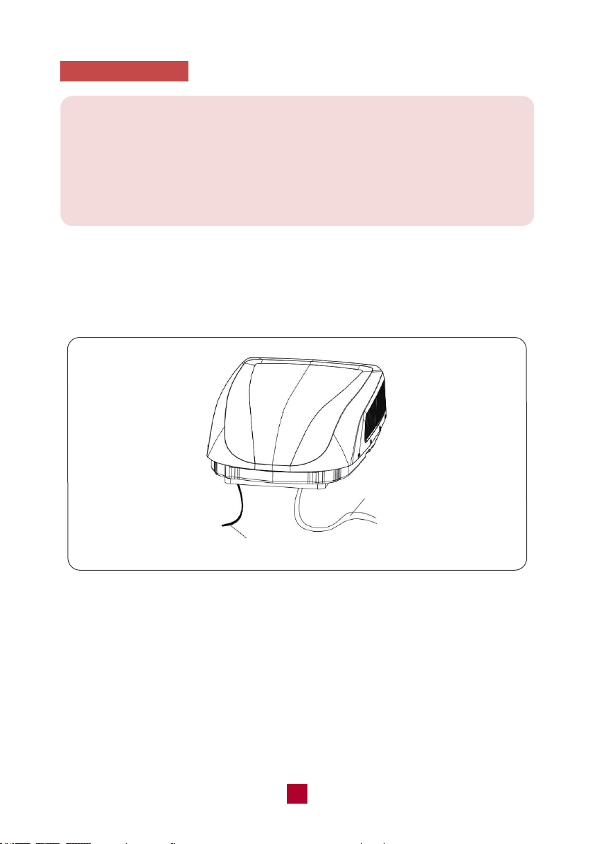
● As shown in Figure 11, the outdoor unit has two sets of outgoing wires: the power
cord (high current) and the control signal wire. The power cord should be directly
connected to the terminal box while the control signal wire should be connected to
the control signal wire of the indoor unit.
● Use copper wire with ground and supply with a minimum of 14 AWG (not included),
for the wiring from the power source to the junction box. Do not attach them at this
time.
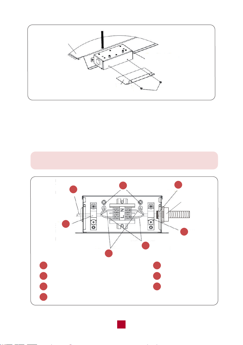
● Remove the 2 screws of the junction box cover. Take the power cord and push it
into the box through the strain relief clamp that is provided (see Figure 12).
Figure 11
Control Signal Wire
Power Cord
16
Note: When connecting the power cord, please use the pipe for
preventing cutting the power wire.
● Connect the power cord to the black, white, and ground wires found in the junction
box with a terminal board.
CAUTION: Connect black wire to black wire, white wire to white wire, and the ground
wire to earth. (see Figure 13)
Pipe
1
Power cord comes from the rooftop unit
2
Ground wire (yellow-green)
3
Power supply wire (not included)
5
Neutral wire (white)
6
Live wire (black)
7
Stain relief (clamp)
4
Stain relief (clamp)
2
1
3
4
5
6
7
Figure 13
Figure 12
Frame
Cover
Junction Box
2 Screws
17
● Tighten the strain relief clamp to secure the supply power cord. Be careful not
over tighten.
● Reinstall the junction box cover.
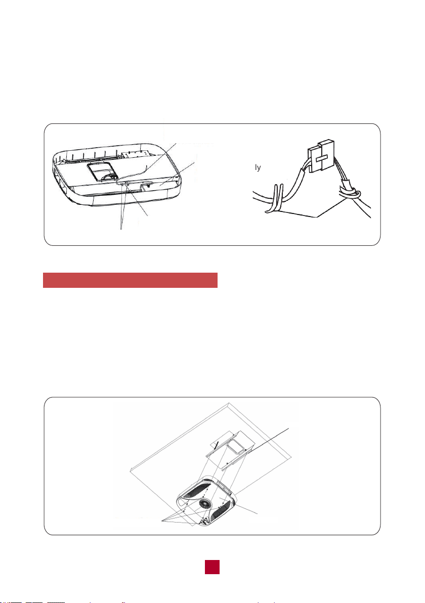
● Connect the connector of indoor and outdoor control signal wire and secure the
clamp (see Figure 14).
6. Install the Ceiling Assembly Grille
● Make sure the guide louver and the filters are properly positioned in the ceiling
grille.
● Secure the ceiling grille to the ceiling assembly frame with 4 screws.
(see Figure 15)
● Install screw caps into four screw holes.
● Switch on the power supply and check whether the unit is working or not.
Figure 15
Ceiling Grille
4 Screws with
Screw cap
Frame
Figure 14
Control Signal Wire
from the Roof Top Unit
Display Box of
Ceiling Assembly
Connector
Clamp
Clamp
19
Operation
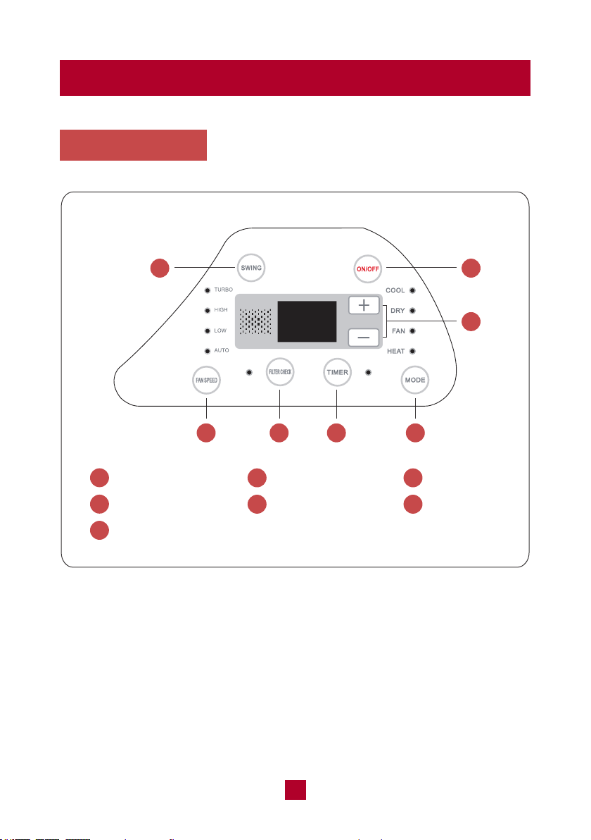
Control Panel
1
4
7
2
5
1
74 65
Swing Button
Fan Speed Button
Mode Button
ON/OFF Button
Filter Check Button
3
6
+/- Button
Timer Button
2
3
18

Note: This button is not valid under dry and fan model.
19
Swing Button
Press this button to activate the automatic air swing function.
ON/OFF Button
Press to power the air conditioner ON or OFF.
+/- Button
● Pressing this button will allow you to change the temperature setting.
● After pressing the timer button, the +/- buttons will adjust the timer setting from
0.5-24 hours in 0.5-hour increments. After the 10-hour mark, the +/- button will
adjust the timer setting in 1-hour increments. It will take 5 seconds for the timer
settings to be confirmed by the machine.
Fan Speed Button
Pressing this button will cycle the fan speed through LOW, HIGH, and TURBO.
Filter Check Button
After 250 hours of operation the Filter Check button will illuminate to remind you
to remove and clean the filter.
When you re-install the air filter and turn on the unit, the light will still be on.
Pressing this button will turn off the light.
Timer Button
● When the unit is running, press this button to schedule when the unit will power
off by using the +/- button to adjust the length of time before powering off.
● When the unit is not running, press this button to schedule when the unit will
power on by using the +/- button to adjust the length of time before powering on.
Mode Button
Pressing this button will cycle through the following modes through COOL, DRY,
FAN, and HEAT.
4
3
2
1
5
6
7
19
20
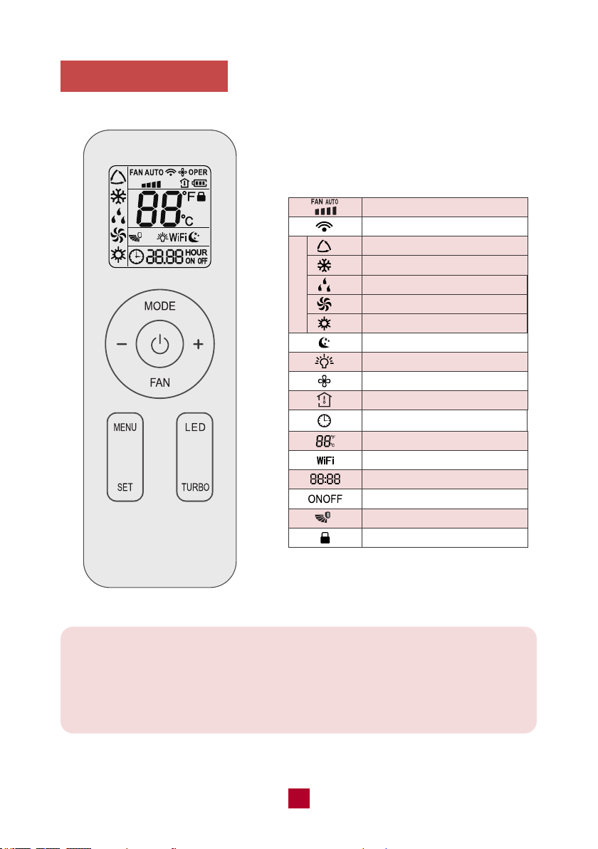
Remote Control
Function icons:
Operation Mode
Fan Speed Setting
Send Signal
Auto Mode
Cool Mode
Dry Mode
Fan Mode
Heat Mode
Sleep Mode
Display Light
X-FAN Function
Indoor Ambient Temp
Clock
Temperature Setting
WIFI Function
Timer Setting
Timer On/Off
Up & Down Swing
Child Lock
Note:
This is a universal remote control for a variety of different models. If your model
does not have a function listed on the remote control when you press the
corresponding button on the remote controller, the unit will keep the original
setting and there will be no changes in the operation of your unit.
Note: After starting up the heat mode, the indoor unit will delay 1-5
minutes before it starts blowing air. The actual delay time will depend on
the current indoor temperature.
19
21
● Once the unit is powered on the air conditioner will give out a sound and the
power indicator will light up. After that, you can operate the air conditioner by
using the remote control.
● When pressing a button on the remote control, the signal icon on the remote
control will blink once and the air conditioner will emit a single beep sound,
which means the signal has been sent to the air conditioner. The remote control
will display the active function icons.
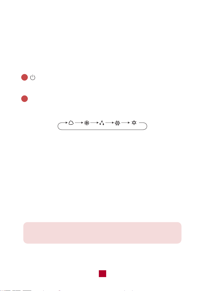
Button
Press this button to turn on the unit. Press this button again to turn off the unit.
MODE Button
Press this button to cycle through the following modes:
Auto mode: The air conditioner will operate automatically according to ambient
temperature. The set temperature can't be adjusted and will not be displayed.
Pressing the “FAN” button can adjust the fan speed.
Cool mode: The air conditioner will operate under standard cooling mode. The set
temperature and fan speed can be adjusted.
Dry mode: The air conditioner will run at low speed for dehumidification. The fan
speed cannot be adjusted.
Fan mode: The air conditioner will not produce cool or warm air, only blow air from
the current room temperature. The fan speed can be adjusted.
Heat mode: The air conditioner operates under heat mode instead of cooling. The
set temperature and fan speed can be adjusted.
2
1
AUTO COOL DRY FAN
HEAT
19
22
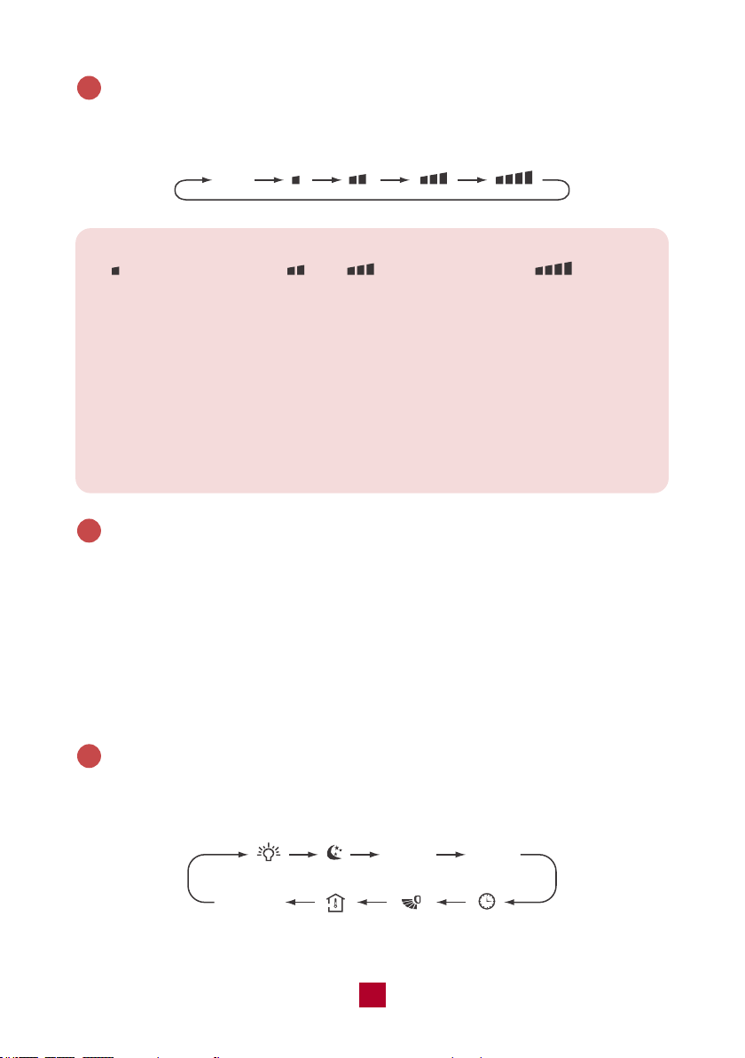
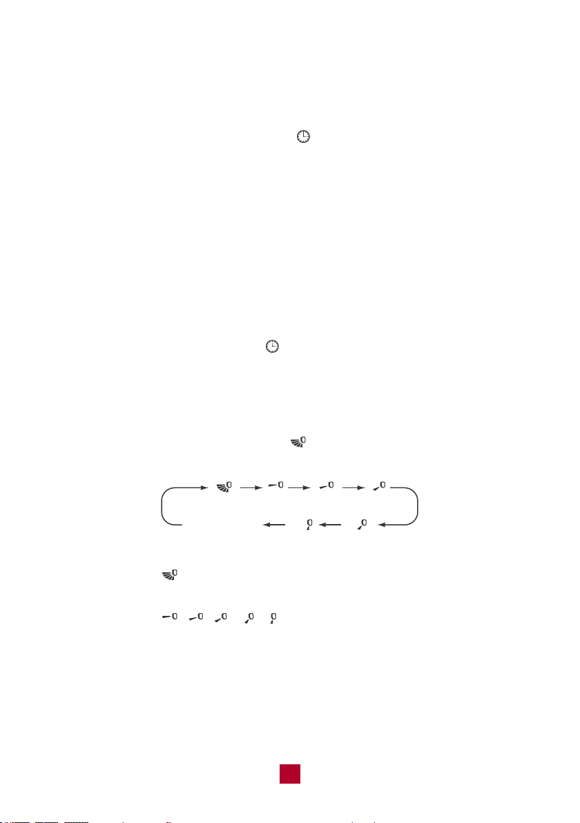
FAN Button
Press this button to cycle through the Auto fan mode and 3 fan speeds (Low, High,
TURBO)
3
Auto
Note:
● indicates low speed, and indicate high speed, indicates
turbo speed.
● Under AUTO fan mode, the air conditioner will select the proper fan speed
automatically.
● X-FAN Function: Hold the fan button for 2 seconds in COOL or DRY mode.
When you turn the machine off you will find the fan is running at a low speed
and will automatically stop. X-FAN is not available in AUTO, FAN, or HEAT
modes. To shut the X-FAN off after powering the unit off, hold the fan button
for 2 seconds.
+/- Button
● Pressing the “+” or “-” button will increase/decrease the set temperature by 1°F.
Holding the button for 2 seconds will cause the temperature to change rapidly.
Release the button once your desired temperature is reached. The set temperature
range is 61°F - 86°F (16°C - 30°C).
● After pressing the Timer button, each press of the +/- button will increase/decrease
the time by 1 minute. Holding the button for 2 seconds will cause the timer to
change rapidly. Release the button once your desired time setting has been reached.
MENU & SET Button
Press this button to select other functions and then press the “SET” button to set
the function status. The functions can be selected circularly as follows:
4
5
TIMER
ON
blank
No Setting
TIMER
OFF
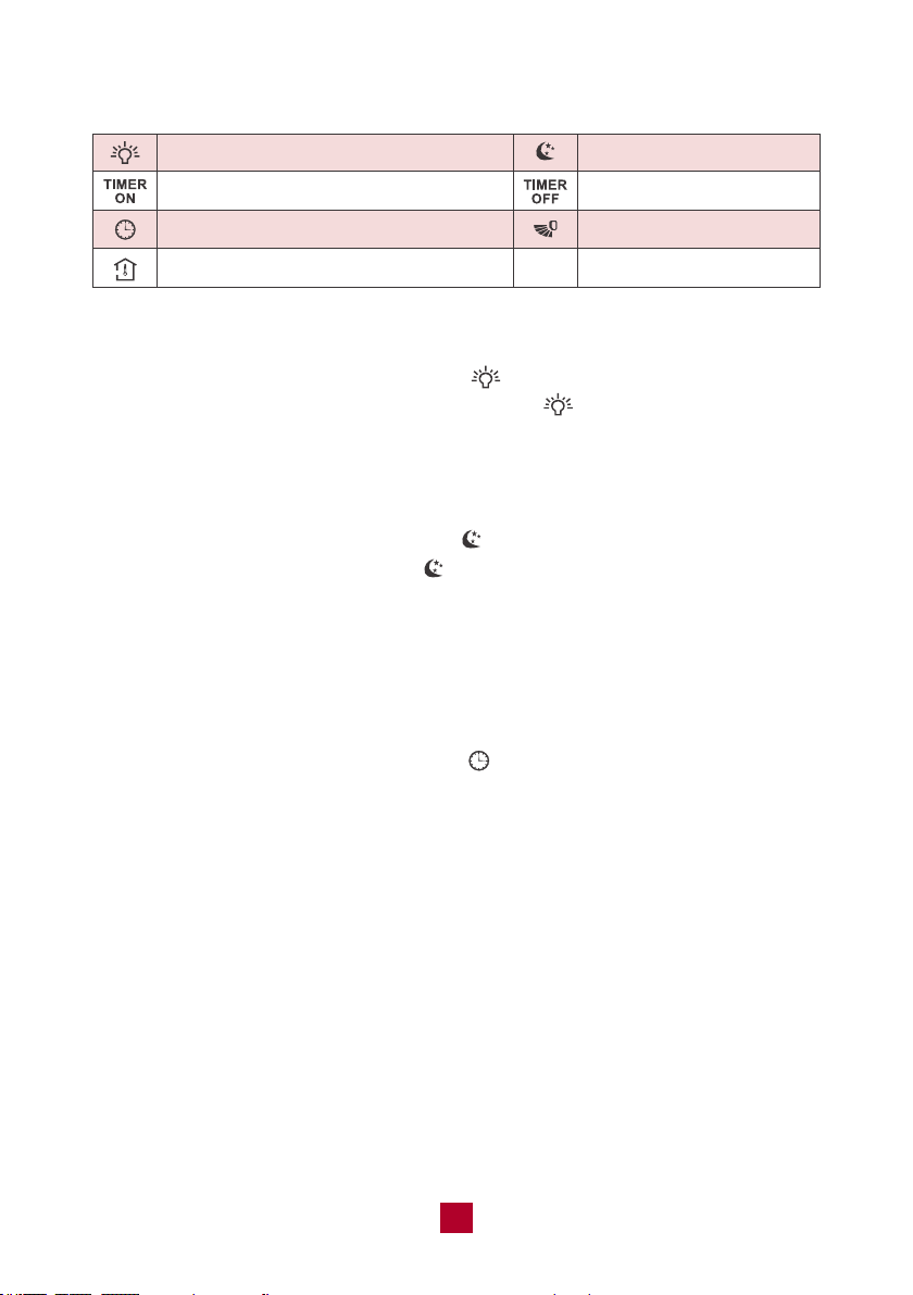
▷ Display Light Function
Press the MENU button until the light icon “ ” flashes then press the “SET” button
to turn off the display light on the indoor unit. The “ ” icon on the remote control
will disappear. Press the “SET” button again within 5 seconds to turn on the display
light.
▷ Sleep Mode
● Press the MENU button until the icon “ ” flashes then press the “SET” button
to turn on the sleep function. The “ ” icon will display on the remote control.
● Press the “SET” button again within 5 seconds to exit sleep mode.
▷ TIMER ON Function
TIMER ON function can set the time to turn on the unit.
● Press the MENU button until the “ON” icon flashes then press the “SET” button
to enter the timer function setting. The “ ” icon will disappear and the word
“ON” on the remote control will blink blinks.
● Use the +/- buttons to adjust the length of the timer before the unit powers on.
The timer setting will increase or decrease by 1 minute with each press of the
“+” or “-” button. Holding the “+” or “-” button for 2 seconds will change the time
rapidly. Press the “SET” button to confirm the timer and the word “ON” will stop
blinking.
● Cancel TIMER ON: Press the MENU button until the “ON” icon flashes then press
the “SET” button until the flashing “ON” disappears.
19
23
Display Light Sleep Mode
Timer On
Clock (not available for this mode)
Indoor Ambient Temp
Timer Off
Up & down Swing
19
24
▷ TIMER OFF Function
TIMER OFF function can set the time to turn off the unit.
● Press the MENU button until the “OFF” icon flashes then press the “SET” button
to enter the timer function setting. The “ ” icon will disappear and the word
“OFF” on the remote control will start blinking .
● Use the +/- buttons to adjust the length of the timer before the unit powers off.
The timer setting will increase or decrease by 1 minute with each press of the
“+” or “-” button. Holding the “+” or “-” button for 2 seconds will change the time
rapidly. Press the “SET” button to confirm the timer and the word “OFF” will stop
blinking.
● Cancel TIMER OFF: Press the MENU button until the character “OFF” flashes then
press the “SET” button until the flashing “OFF” disappears.
▷ Clock Function
● Press the MENU button until the “ ” icon flashes then press the “SET” button
to enter the clock setting.
● Use the +/- buttons to adjust the clock to match the real time.
▷ Up & Down Swing Function
● Press the MENU button until the icon “ ” flashes then press the “SET” button
to select airflow directions.
● When selecting , the horizontal louvers will automatically swing up & down
across the maximum range.
● When selecting , , , , , the unit will blow air at a fixed position.
The horizontal louvers will not move.
no display
(horizontal louvers
stops at current position)

19
25
LED Button
Not available for this model.
6
TURBO Button
In COOL/HEAT mode, press this button to start QUICK COOL/QUICK HEAT. When
in TURBO mode, the “ ” icon will display on the remote control. The unit will run
at super-high fan speed to cool/heat quickly so that the ambient temperature
approaches the preset temperature as soon as possible.
7
Combination Buttons
● Child Lock
Press the “+” and “-” buttons simultaneously to enter the child lock function. While
in this mode, the remote control will display the “ ” icon and will not send any
signal to the air conditioner. If you operate the remote controller, the “ ” icon will
blink 3 times without sending a signal to the unit.
● Change Between °F and °C
With the remote powered off, press the Mode and “-” buttons simultaneously to
switch between Fahrenheit and Celsius displays.
● WiFi Function
Press the “MODE” and “TURBO” buttons simultaneously to turn on/off the WiFi
function.
When the WiFi function is turned on, the remote control will display the “WiFi” icon.
Long press the “MODE” and “TURBO” buttons simultaneously for 10s to reset WiFi
to factory settings.
▷ Indoor Ambient Temperature Display Function
● Press the MENU button until the icon “ ” flashes then press the “SET” button
to turn on this function. The “ ” icon will display on the remote control. The
indoor unit displays the corresponding temperature and then automatically turns
to display the set temperature after a few seconds.
● Press the “SET” button again within 5 seconds to turn off this function.
26
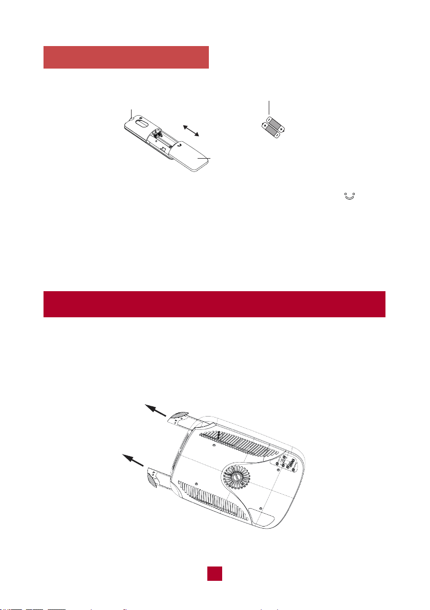
1. Press the back side of the remote control battery cover marked with “ ”, and
slide out following the engraved arrow.
2. Replace with two new AAA(1.5V) batteries of the same make and model. Make
sure the polarities (+ & -) are aligned correctly.
3. Reinstall the battery cover box.
Replacing the Batteries
Battery
Signal Sender
Reinstall
Remove
Cover of Battery Box
Cleaning and Maintenance
Cleaning the filter
1. Remove the filter
Remove the air filters by pulling them as illustrated below.
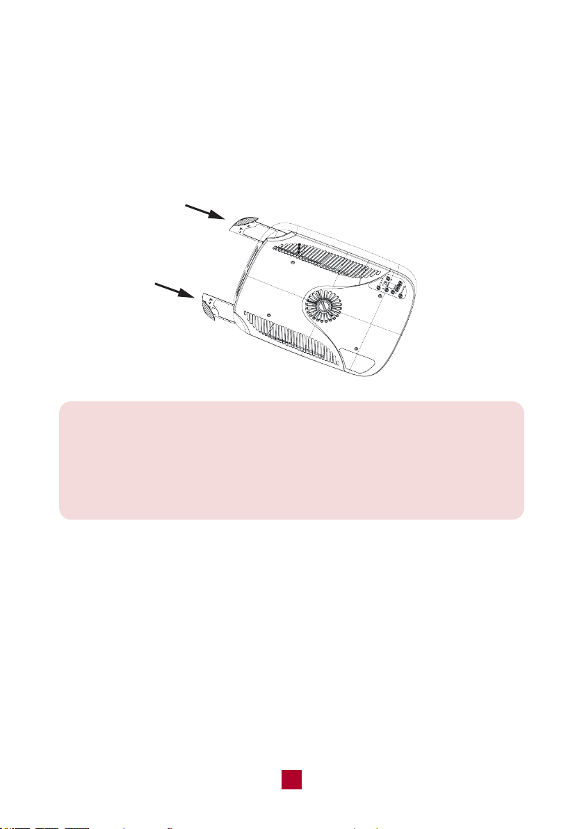
27
Note:
● Clean the filter when the air conditioner FILTER CHECK light is on.
More frequent cleaning may be necessary depending on the air quality.
● Do not operate the air conditioner if the air filter is missing.
● Remove the cover and wash the condenser coil twice a year.
2. Clean the filter
After removing, wash away dust from the air filters with clean water or vacuum the
filter with an electric household vacuum cleaner.
3. Reinstall the filter
Make surer the filters are completely dry before reinstalling. Place them back into
the AC unit.
Warning
● Don’t touch the capacitor terminals without the electric discharge. The capacitor
still may have a high voltage even though the power supply is turned off.
● To prevent water leakage, do not block the filter and the indoor air inlet.
28
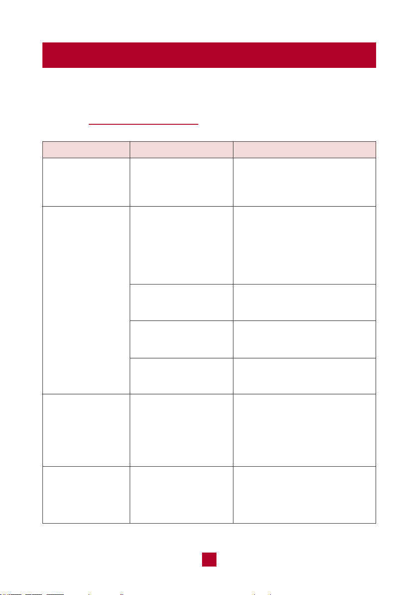
Troubleshooting
You may meet some common issues listed below. We recommend you do a
self-check first, but if the problem is not resolved, please contact customer
support at [email protected].
Whether the unit is
connected to the power
supply correctly?
Whether the rooftop
air conditioner is level?
Whether the set
temperature is proper?
Whether the air filter
is too dirty?
Has the unit just been
turned on or off?
Has the unit just been
turned on or off?
Has the chassis
gasket been evenly
compressed and
tightened?
Check the power supply of the
vehicle and make sure it is
provided correctly.
Mount the rooftop air conditioner
as level as possible from front to
rear and side to side when the
vehicle is parked. Make sure
that the mounting of the air
conditioner is correct and level.
Adjust the temperature.
Clean the air filter.
Allow a sufficient amount of time
for the unit to cool/heat the room.
The flowing water sound is the
refrigerant inside the air
conditioner, which is completely
normal.
Mounting bolts should be
tightened evenly by compressing
the chassis gasket.
Air conditioner
can't operate
Poor cooling
(or heating)
There's an
abnormal sound
during operation,
such as clicking
or gurgling
There’s water
dripping inside
the unit
Issues Self check Possible solutions

Whether the
temperature is low
inside?
Whether the air filter
is too dirty?
Select FAN mode at HIGH
fan speed.
Clean the air filter.
Ice or frost
appeared on
the coils
Issues Self check Possible solutions
29
● If you notice or experience any of the following conditions, please turn off the
air conditioner, disconnect from power, discontinue use, and contact support
immediately.
○ Abnormal sound during operation, not mentioned above.
○ A strange odor is emitted from the unit
○ Excessive water leakage from the unit
● Do not attempt to repair or retrofit the air conditioner by yourself. All repairs must
be performed by qualified individuals.
30
Malfunction Codes
E6 / E8
PL
F1 / F2 / F3 / F4
Error code Trouble shooting
It can be eliminated after restarting the unit.
If not, please contact support for help.
Please check whether the voltage is correct. It can be
eliminated after restarting the unit.
If not, please contact support for help.
Please contact the support for help.
Note: If other error codes appear, please contact our customer support
team for help.
31
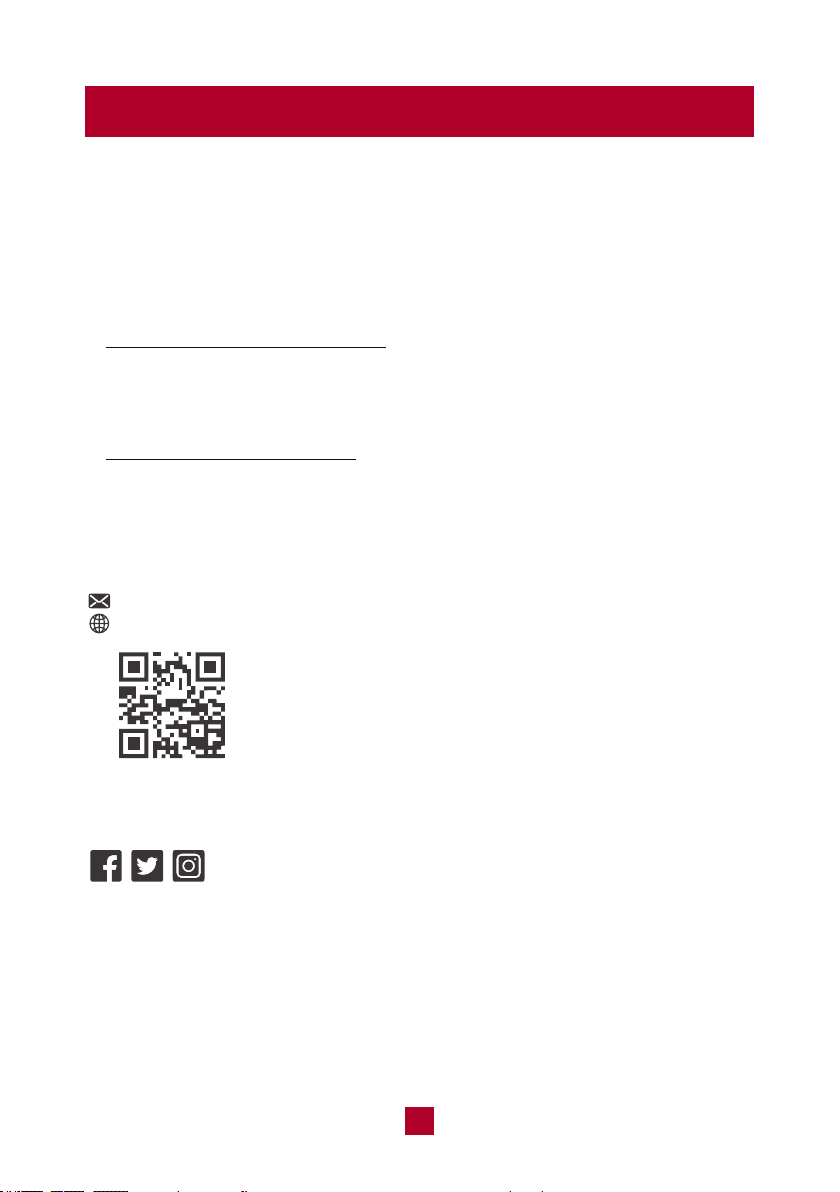
Warranty & Customer Support
Warranty Information
1. 2-Years warranty:
TOSOT RV Air Conditioner comes with a 2-years warranty from the date of
purchase.
This warranty covers manufacturing and material defects. Please visit
https://tosotdirect.com/warranty for more details.
2. Additional 6-Month warranty extension:
You can get a 6-month warranty extension by registering your new product
at
www.tosotdirect.com/extend
VTST20230404
.
Customer Support
Questions? We are here to help
support@tosotdirect.com
www.tosotdirect.com
@tosotdirect
Share your experience