Installation
Operation
Maintenance
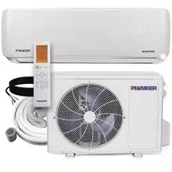
Owner’s Manual
RV ROOFTOP INVERTER HEAT PUMP AIR CONDITIONER
MODEL NO: PYZ012AZUDCIPD
IMPORTANT NOTICE:
Please read this manual carefully before installing
or operating your new air conditioning system.
Be sure to save this manual for future reference.
Wireless
Internet
Ready
FCC IDENTIFIER:2ANDL-CB3S
REV112124
304793

I. Operational Instructions.......................................................................1
1. Safety Information................................................................................................................................................1
2. Scope and Purpose of is Manual........................................................................................................................2
3. Model Number and Technical Details Identication.............................................................................................2
4. Handling Procedures.............................................................................................................................................3
5. Usage Information.................................................................................................................................................9
6. Best Practices for Optimal Performance................................................................................................................10
7. Warnings and Safety Precautions for A2L Refrigerant...........................................................................................10
8. Description of the Controls.................................................................................................................................11
9. Automatic Mode Operation.................................................................................................................................12
10. Cooling Mode Operation..................................................................................................................................12
11. Dehumidication Mode Operation...................................................................................................................13
12. Ventilation Mode Operation..............................................................................................................................13
13. Heat Pump Mode Operation.............................................................................................................................14
14. Night Mode Operation......................................................................................................................................14
15. Timer On and Timer O Mode Operation........................................................................................................15
16. Handling of the Remote Controller...................................................................................................................16
17. Description of the Decorative Panel...................................................................................................................16
18. Wi-Fi Connection and Instructions for Usage....................................................................................................17
19. Routine Maintenance........................................................................................................................................18
II. Installation Instructions....................................................................19
1. Getting Started....................................................................................................................................................19
2. Installation Positioning........................................................................................................................................19
3. Guidelines for a Successful Installation.................................................................................................................20
4. Dimensional Information....................................................................................................................................20
5. Creation of Roof Opening...................................................................................................................................21
6. Electrical Setup....................................................................................................................................................22
7. Opening Treatment.............................................................................................................................................22
8. Placement of Air Conditioner Onto Roof.............................................................................................................23
9. Interior Mounting and Connections....................................................................................................................24
10. Installation of Air Duct Foam............................................................................................................................25
11. Electrical Wiring................................................................................................................................................26
12. System Connections..........................................................................................................................................27
13. Mounting the Panel...........................................................................................................................................28
14. Initialization of System......................................................................................................................................29
III. DIAGNOSTICS , TECHNICAL CHARACTERISTICS , RECYCLING.........30
1. Troubleshooting..................................................................................................................................................30
2. Error Code Interpretation....................................................................................................................................30
3. Technical System Information..............................................................................................................................31
4. European Disposal Guidelines.............................................................................................................................33
Table of Contents
INSTRUCTIONAL HANDBOOK
1
Safety Information
OPERATIONAL INSTRUCTIONS
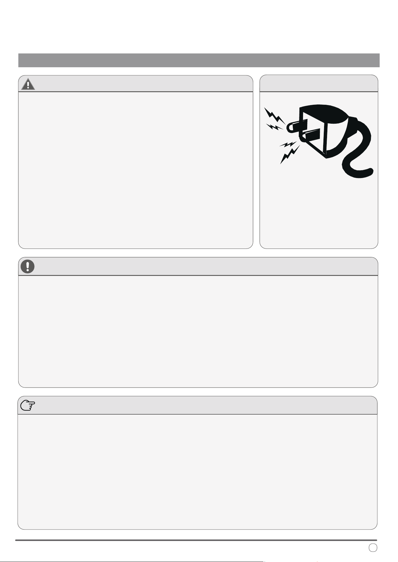
CAUTION - Read Before You Proceed
Read and Understand All Safety Precautions Prior to Installation
For safe operation, it is imperative that the following rules are obeyed:
• is appliance can only be used by children aged 8 years and above,
or by persons with reduced physical, sensory, or mental capabilities,
or persons with lack of experience and knowledge, if they have been
given supervision or instructions concerning usage of the appliance
in a safe way and understand the potential hazards involved.
• Children shall not play with this appliance. Proper cleaning and user
maintenance shall not be done by children without supervision.
• is appliance should only be installed by those whom are qualied
and suciently trained to do so, following the instructions herein.
• Modication of this product is an extremely dangerous operation,
and may lead to personal injury or loss of property.
Failure to abide by the
manufacturer cautions
can result in property
damage, personal
injury and/or death.
Electrical Danger
WARNING - e Manufacturer Is Not Liable For the Following:
•
Units that have sustained damage due to improper installation or have been connected with an incorrect
voltage. Abide by the installation instructions fully and completely to prevent unexpected malfunctions.
Note about Fluorinated Gasses and Operation of the System
1.
is air-conditioning unit contains uorinated gasses. For specic information on the type of gas and the
amount, please refer to the relevant label on the unit itself. Some refrigerants may not exude an odor.
2.
3.
4.
5.
6.
•
Products that have had extra modications, where written consent was not provided by the manfacturer.
•
Product usage in a way that is not the intended purpose as described in this operational instruction manual.
•
Any sort of collateral damage to property or injuring to nearby persons caused by failure of the product.
Installation, service, maintenance, and repair of this unit must be performed by a certied HVAC technician,
or qualied personnel familiar with the risks of handling refrigerant and regulations of air conditioner systems.
Product uninstallation and recycling must be performed by a certied HVAC technician.
e system and/or its internal moving parts should not be touched, poked, or prodded during operation.
Do not use the system near combustible objects or ammable uids. Keep a distance of at least 2 feet from
other nearby appliances. If a re occurs, a proper extinguishing agent, rather than water, must be used.
When the unit is being checked for leaks, proper logging and record-keeping of all checks by certied personnel is
strongly recommended. Refrigerant must never be released into the air, a proper recovery device should be used.
•
Improperly grounded products. e product must be properly grounded at the time of installation, else
electrical shock may occur.
•
Incorrect conguration of drainage. Install drainage channels according to the instructions in this manual.
Improper drainage may cause water damage to your vehicle and property.
2
Scope and Purpose of is Manual
OPERATIONAL INSTRUCTIONS
Model Number and Technical Details Identication
is manual has been specically compiled by the manufacturer and is an essential
component of the machine. e information contained within can guarantee
proper usage of the machine, if observed and followed carefully.
Sections I and III are intended to provide helpful instructions and knowledge to
the end user. Section II is intended to intruct the installer, who should be a person
that possesses expert knowledge and experience in this eld of work.
Where applicable, some portions of text may be accompanied by certain symbols,
that of which can be understood by referencing the below table:
is symbol indicates a potential source of danger.
is symbol indicates useful information or a helpful tip.
is symbol indicates information on being environmentally friendly.
Product details may vary and can change at any time, consult physical namebadge for best accuracy.
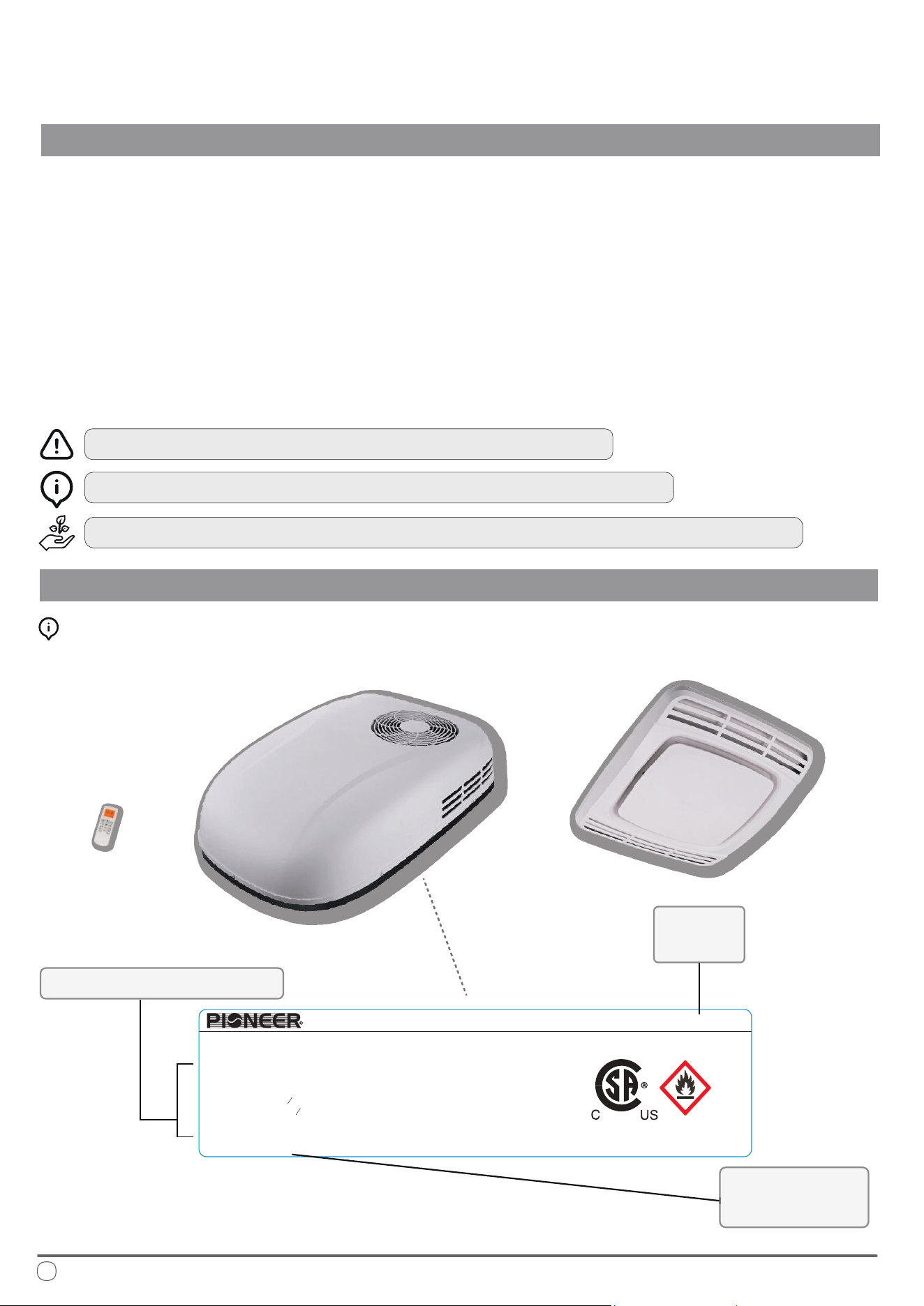
Interpreting the Rating Label:
Technical Specications
Model
Number
Supplier
Information
304793
13.5K RV ROOF AIR CONDITIONER(Inverter)
Model : PYZ012AZUDCIPD
A2L
Global Warming Potential: 675
Refrigerant R32 : 560 g/19.75 oz
3
Rated Input Current of the Power
Conversion Equipment: 11 A
MIN. CIR. AMPS 16 AMPS
MAX. CIR. PROTECTION 25 AMPS
Maximum allowable Pressure(High Side):
6.0 MPa / 870 PSIG
Degree of Protection (Outside IP): IPX4
Power: 115V~/60Hz/1Ph
Cooling Capacity (Btu/h): 7,500~13,500
Heating Capacity (Btu/h): 7,200~13,500
Indoor Fan Motor:
1
HP FLA - 0.8 A
15
Outdoor Fan Motor:
4
H
9
P FLA - 1.0 A
MADE IN CHINA
Date of Manufacture: See barcode
PARKER DAVIS HVAC INTERNATIONAL Miami, FL - www.pdhvac.com - (800)-675-7410

3
Handling Procedures
OPERATIONAL INSTRUCTIONS
• Do not use any methods other than those recommended by the manufacturer to accelerate the defrosting process
or to clean the appliance.
• e appliance must be stored in a room free from continuously operating open ames, ignition sources (e.g., an
operating gas appliance or electric heater), or other sources of ignition.
• Ensure that the appliance is stored in a way that prevents mechanical damage.
• Do not pierce or burn the appliance.
• Be aware that refrigerants used in this appliance may not have an odor, so leaks may not be immediately
detectable.
• Store the appliance in a well-ventilated area, ensuring the room size meets the minimum area requirements
specied for safe operation.
• Compliance with national gas regulations must be observed. e minimum applicable area for this machine is
160 ft². Ensure that there are no obstacles in front of the machine and keep ventilation openings clear of any
obstructions.
• Servicing should only be carried out as recommended by the manufacturer.
• Any person working on or accessing the refrigerant circuit must hold a valid certicate from an industry-accredited
authority, conrming their competence to handle refrigerants safely according to recognized industry standards.
• Maintenance and repairs requiring additional skilled personnel should be conducted under the supervision of a
person qualied in the safe handling of ammable refrigerants.
Before starting work on systems containing flammable refrigerants, safety checks must be conducted to minimize the risk of
ignition. When repairing the refrigeration system, the following precautions must be observed before beginning work:
Work Procedure
All work should be carried out under controlled conditions to minimize the risk of flammable gases or vapors being
present while the work is in progress.
General Work Area
• All maintenance personnel and others in the vicinity must be informed of the nature of the work being conducted.
• Avoid working in confined spaces whenever possible.
• Section off the area around the workspace to restrict access.
• Ensure that the area is safe by controlling any flammable materials present.
No Ignition Sources
Anyone working on a refrigeration system that involves exposing any pipework containing or that has contained
flammable refrigerant must ensure that no ignition sources are used in a way that could lead to a fire or explosion.
All potential sources of ignition, including cigarette smoking, must be kept at a safe distance from the site of
installation, repair, removal, or disposal, where flammable refrigerant could be released into the surrounding area.
Before beginning work, inspect the area around the equipment to ensure there are no flammable hazards or ignition
risks. Ensure the area is either outdoors or well-ventilated before breaking into the system or performing any hot
work. Ventilation should be maintained throughout the work to safely disperse any released refrigerant, preferably
directing it safely to the outside atmosphere.
PRELIMINARY PRECAUTIONS

4
Handling Procedures
OPERATIONAL INSTRUCTIONS
PRELIMINARY PRECAUTIONS (CONT’D)
Checks for Refrigeration Equipment
When replacing electrical components, ensure they are suitable for the intended purpose and meet the correct
specifications. Always follow the manufacturer’s maintenance and service guidelines. For any uncertainty, consult the
manufacturer’s technical support for assistance.
The following checks must be performed on installations using flammable refrigerants:
Refrigerant Charge Size: Ensure that the charge size is appropriate for the room size where refrigerant-containing
parts are installed.
Ventilation: Verify that ventilation equipment and outlets are functioning properly and are unobstructed.
Indirect Refrigeration Circuit: If using an indirect refrigeration circuit, inspect the secondary circuit to confirm the
absence of refrigerant.
Equipment Markings: Ensure that all markings on the equipment remain visible and legible. Replace any illegible
markings or signs.
Corrosion Prevention: Confirm that refrigeration pipes or components are installed in a location where they are
unlikely to be exposed to substances that could corrode refrigerant-containing parts. If exposure is possible, ensure
the components are made from materials resistant to corrosion or are adequately protected.
Checking for Presence of Refrigerant
• Before and during work, use an appropriate refrigerant detector to check the area for potentially flammable
atmospheres.
• Ensure that the leak detection equipment is suitable for flammable refrigerants (i.e., non-sparking, adequately
sealed, or intrinsically safe).
• Presence of Fire Extinguisher
• If any hot work is required on the refrigeration equipment or related parts, have suitable fire extinguishing
equipment readily available.
• A dry powder or CO2 fire extinguisher should be placed near the charging area.
Checks for Electrical Devices
Repair and maintenance of electrical components must include initial safety checks and thorough inspection
procedures. If a fault is identified that could compromise safety, the electrical supply should not be connected until
the issue is resolved. If the fault cannot be immediately corrected but operation must continue, a suitable temporary
solution may be applied. This should be communicated to the equipment owner to ensure all parties are informed.
Initial safety checks should include:
• Ensuring capacitors are safely discharged to prevent any risk of sparking.
• Verifying that no live electrical components or wiring are exposed while charging, recovering, or purging the
system.
• Confirming continuity of earth bonding.

5
Handling Procedures
OPERATIONAL INSTRUCTIONS
Repairs to Sealed Components
When repairing sealed components, disconnect all electrical supplies from the equipment before removing any
sealed covers or similar parts. If it is absolutely necessary to have an electrical supply during servicing, a continuously
operating leak detection device should be positioned at the most critical point to provide early warning of a
potentially hazardous situation.
Take particular care to ensure that repairs do not compromise the protective casing of electrical components. This
includes avoiding:
• Damage to cables,
• Excessive or improper connections,
• Use of terminals that don’t meet original specifications,
• Damage to seals, or
• Incorrect fitting of cable glands.
Ensure that all components are securely mounted, and that seals or sealing materials have not degraded to the point
where they no longer prevent the ingress of flammable atmospheres. Replacement parts should be consistent with
the original specifications.
Note: Be aware that using silicone sealant may impair the effectiveness of certain types of leak detection equipment.
Exception: Intrinsically safe components do not need to be isolated before working on them.
Repair of Intrinsically Safe Components
Do not apply any permanent inductive or capacitive loads to the circuit without verifying that they do not exceed
the permissible voltage and current limits for the equipment in use. Intrinsically safe components are the only types
that may be worked on while live in the presence of a flammable atmosphere. Ensure that the test apparatus is
correctly rated for the task.
Replace components only with parts specified by the manufacturer, as using non-specified parts may lead to
ignition of refrigerant from a potential leak.
Cabling
Ensure that cabling is protected from potential wear, corrosion, excessive pressure, vibration, sharp edges, or any
other adverse environmental effects. Consider the impact of aging and constant vibration from components like
compressors or fans when assessing cable durability.
Detection of Flammable Refrigerants
Under no circumstances should potential sources of ignition be used to search for or detect refrigerant leaks. Do not
use a halide torch or any other detector that involves an open flame.
MAINTENANCE, SERVICING, & REPAIRS

6
Handling Procedures
OPERATIONAL INSTRUCTIONS
MAINTENANCE, SERVICING, & REPAIRS (CONT’D)
Leak Detection Methods
The following methods are acceptable for detecting leaks in systems containing flammable refrigerants:
Electronic Leak Detectors: Use electronic detectors to identify flammable refrigerants; however, ensure that the
sensitivity is sufficient and recalibrate as necessary. Calibration should be performed in a refrigerant-free area.
Confirm that the detector is not a potential ignition source and is compatible with the refrigerant in use.
Calibration Settings: Set the leak detection equipment to a percentage of the refrigerant’s Lower Flammability
Limit (LFL) and calibrate it to the specific refrigerant being used. Verify that the gas concentration does not exceed
25% of the LFL.
Leak Detection Fluids: Most refrigerants are compatible with leak detection fluids, but avoid detergents containing
chlorine, as chlorine can react with the refrigerant and corrode copper piping.
Safety Precautions: If a leak is suspected, extinguish all open flames in the area.
Brazing Leaks: If a refrigerant leak requiring brazing is detected, recover all refrigerant from the system or isolate it
in a section of the system away from the leak using shut-off valves. Purge the system with oxygen-free nitrogen
(OFN) before and during the brazing process.
Removal and Evacuation
When accessing the refrigerant circuit for repairs or other purposes, use conventional procedures, but adhere to best
practices due to flammability considerations. The following steps should be followed:
Remove the Refrigerant: Recover the refrigerant into appropriate recovery cylinders.
Purge with Inert Gas: Purge the circuit with an inert gas such as oxygen-free nitrogen (OFN).
Evacuate the System: Evacuate the system to remove any remaining gases.
Purge Again: Perform a second purge with inert gas.
Open the Circuit: Open the circuit by cutting or brazing as needed.
The system should be “flushed” with OFN to ensure it is safe. This flushing process may need to be repeated several
times. Do not use compressed air or oxygen for this purpose.
To flush the system, break the vacuum with OFN until the working pressure is reached, vent to the atmosphere,
then pull down to a vacuum. Repeat this process until no refrigerant remains in the system. When applying the final
OFN charge, vent the system down to atmospheric pressure to allow for safe work, especially if brazing operations
are required on the pipework.
Ensure the outlet of the vacuum pump is kept away from any ignition sources and that the area is well-ventilated.

7
Handling Procedures
OPERATIONAL INSTRUCTIONS
MAINTENANCE, SERVICING, & REPAIRS (CONT’D)
Charging Procedures
In addition to standard charging procedures, observe the following requirements:
Prevent Contamination: Take care to prevent cross-contamination of different refrigerants when using charging
equipment. Hoses or lines should be kept as short as possible to minimize the refrigerant volume they contain.
Cylinder Position: Always keep cylinders upright.
Earthing: Ensure the refrigeration system is properly grounded before charging it with refrigerant.
Labeling: Label the system once charging is complete, if it hasn’t already been labeled.
Avoid Overfilling: Take extreme care not to overfill the refrigeration system.
Before recharging, perform a pressure test on the system with oxygen-free nitrogen (OFN). After charging, but
before commissioning, conduct a leak test. A follow-up leak test should be performed before leaving the site.
Decommissioning
Before starting the decommissioning process, the technician must be thoroughly familiar with the equipment and all
its details. It is recommended to safely recover all refrigerants. Prior to beginning the task, collect an oil and
refrigerant sample in case analysis is needed before reusing reclaimed refrigerant. Ensure that electrical power is
available before starting.
Preparation:
• Review equipment and its operation to ensure familiarity.
• Electrically isolate the system.
Verify the following before beginning:
• Mechanical Handling: Mechanical handling equipment is available if needed for refrigerant cylinders.
• Personal Protective Equipment (PPE): All necessary PPE is available and used correctly.
• Supervision: The recovery process is monitored at all times by a qualified person.
• Standards Compliance: Ensure recovery equipment and cylinders meet appropriate standards.
Recovery Process:
• Pump down the refrigerant system, if possible.
• If a vacuum cannot be achieved, set up a manifold to remove refrigerant from different parts of the system.
Place the recovery cylinder on a scale before starting recovery.
Operation:
• Start the recovery machine and follow the manufacturer's instructions.
• Avoid overfilling cylinders; limit the liquid charge to no more than 80% of the cylinder’s volume.
• Do not exceed the cylinder's maximum working pressure, even temporarily.

8
Handling Procedures
OPERATIONAL INSTRUCTIONS
MAINTENANCE, SERVICING, & REPAIRS (CONT’D)
Completion:
• Once cylinders are filled correctly and the recovery process is complete, remove the cylinders and equipment from
the site promptly.
• Close all isolation valves on the equipment.
• Recovered refrigerant must not be charged into another refrigeration system unless it has been properly cleaned
and inspected.
Recovery
When removing refrigerant from a system for servicing or decommissioning, it is best practice to ensure that all
refrigerants are safely removed. When transferring refrigerant to cylinders, only use appropriate refrigerant recovery
cylinders. Ensure that the correct number of cylinders is available to hold the total system charge. All cylinders used
must be designated and clearly labeled for the specific refrigerant being recovered. They should also be equipped
with pressure relief valves and functional shut-off valves. Empty recovery cylinders should be evacuated and, if
possible, cooled prior to use.
The recovery equipment must be in good working condition, suitable for use with flammable refrigerants, and
accompanied by operating instructions. Additionally, calibrated weighing scales should be available and in proper
working order. All hoses should have leak-free disconnect couplings and be in good condition. Before using the
recovery machine, verify that it is in proper working condition, well-maintained, and that all electrical components
are sealed to prevent ignition in the event of a refrigerant leak. Consult the manufacturer if there is any doubt.
Recovered refrigerant should be returned to the refrigerant supplier using the appropriate recovery cylinder, and a
relevant Waste Transfer Note must be arranged. Do not mix refrigerants in recovery units or cylinders.
If compressors or compressor oils need to be removed, ensure they are evacuated to a safe level to prevent residual
flammable refrigerant from remaining in the lubricant. This evacuation must be done before returning the
compressor to the supplier. To speed up the process, only use electric heating to warm the compressor body. Oil
drained from the system must be handled safely.
INSTALLATION ENVIRONMENT OF THE AIR CONDITIONER
The air conditioner can be installed either during the production phase of the RV or after its completion. It must be
installed horizontally on the top of the RV.
• The minimum spacing between rafters and joists on the roof structure should be 15-3/4 inches.
• The roof thickness of the RV must be at least 1 inch and no more than 4 inches.
• If the roof thickness exceeds 4 inches, an additional air duct connection is required.
Intended Purpose of the Air Conditioner
This air conditioner is designed specifically for RVs to enhance internal temperature control and create a
comfortable environment. It provides cooling during hot weather and heating during cold weather, along with
adjustable temperature settings for both conditions.
Usage Information
OPERATIONAL INSTRUCTIONS
9
OPERATIONAL CHARACTERISTICS
The performance of the air conditioner is influenced by the insulation properties of the RV itself. Users can take
preventive measures to minimize heat entry, thereby enhancing the cooling efficiency of the air conditioning system.
When the outdoor temperature is high, consider the following steps to reduce heat penetration into the RV and
improve system performance:
• Park the RV in a shaded or cool area.
• Enhance the thermal insulation of the compartment, block openings in the vehicle, and use shade curtains,
shutters, or hanging curtains over windows.
• Keep doors and windows closed and limit their opening and closing as much as possible.
• Avoid using heat-generating devices inside the vehicle.
• Turn on the air conditioner in advance for optimal cooling performance.
When indoor or outdoor temperatures are high, setting the air conditioner to cooling mode and using the high fan
speed setting can maximize its performance.
Note: Due to significant changes in air temperature within the vehicle, rapid cooling may cause some condensation to form
on surfaces near the air outlet. This is a normal occurrence. As the air conditioner operates for a longer period, the
condensate will typically dry out and detach from surfaces. To reduce condensation, keep doors and windows closed as much
as possible while the air conditioner is in use. The manufacturer is not liable for any damage resulting from condensation
on the ceiling or other surfaces due to the air conditioner’s operation.
Note:
• Please use connecting wires that comply with national regulations.
• When selecting a generator, consider the total power consumption of the RV.
• Generators may experience power loss at high altitudes or due to insufficient maintenance.
• Circuit Protection: Always use a leakage circuit breaker for safety.
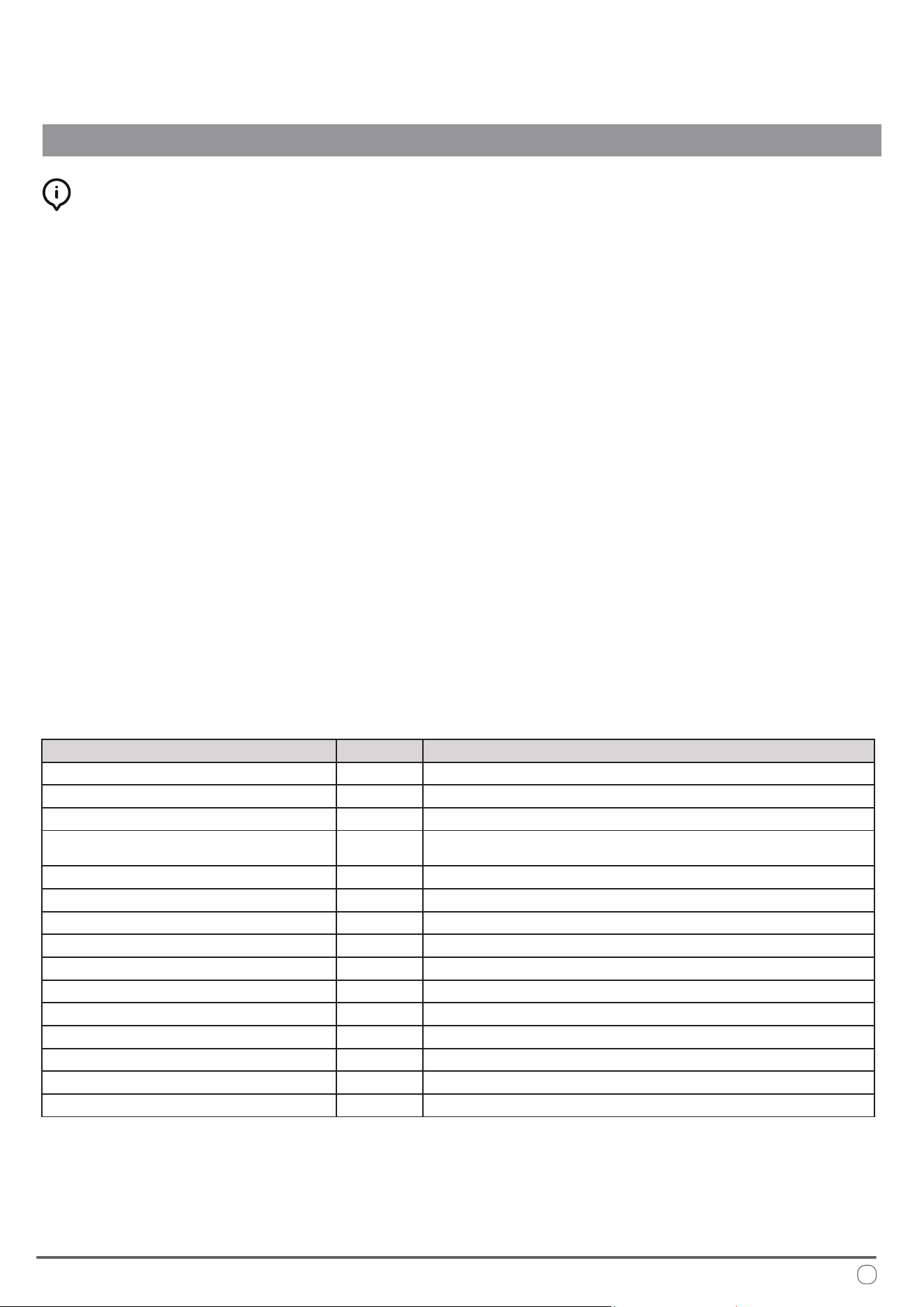
Description Unit Value
Model Number - PYZ012AZUDCIPD
Rated Cooling Capacity (Range) BTU/hr 7500 ~ 13500
Rated Heating Capacity (Range) BTU/hr 7200 ~ 13500
Power Supply / Frequency V / Hz 115 / 60
FLA of Fan Motor (Indoor) A 0.8
FLA of Fan Motor (Outdoor) A 1.0
MCA A 16
MOP A 25
Rated Input Current of the Converter A 11
Refrigerant Type - R32
Refrigerant Amount oz. 19.75
Cable Standard AWG / ft. 12 / <25
Circuit Protection Fuse A 20
Cooling Mode Operational Temperatures °F 63 ~ 109 (Outdoor) / 63 ~ 90 (Indoor)
Heating Mode Operational Temperatures °F 28 ~ 75 (Outdoor) / 28 ~ 81 (Indoor)

Best Practices for Optimal Performance
OPERATIONAL INSTRUCTIONS
For best results, the following tips are given in order to improve the output and
eciency of the machine:
Increase the vehicle’s insulation amount by sealing o openings and covering
glass surfaces with reective or blackout curtains.
When running the machine, select the desired temperature and fan speed and
ensure that the air vents are oriented in a suitable and proper direction.
Avoid the frequent opening of doors and/or windows when not necessary.
To prevent mechanical malfunctions and minimize risk of personal injury, ensure
that the following precautions are abided by:
Avoid obstruction of the ventiled air inlet. Do not cover with cloth, paper, etc.
Do not put hands or insert ngers into any of the machine’s openings.
Do not spray water into or onto the surface of the machine.
Keep ammable substances and objects 3 feet or more away from the machine.
Clean the machine’s air lters periodically.
Warnings and Safety Precautions for A2L Refrigerant
is appliance uses A2L refrigerant, which is classied as mildly ammable. It is critical to follow these safety precautions to minimize
the risk of re or explosion.
Handling and Installation:
• Only qualied personnel should handle A2L refrigerant. Improper handling can cause injury or damage.
• Before servicing, check for ignition sources and ensure proper ventilation. Use a suitable leak detector to conrm the area is safe.
• Ensure all electrical components are rated for A2L refrigerant and avoid any sources of ignition during installation or service.
• When charging the system, ensure proper grounding and secure connections. Avoid overlling the system.
Leak Detection and Repair:
• If a leak is suspected, do not use open ames or spark-generating tools. Use appropriate electronic leak detectors.
• Evacuate and ventilate the area immediately if a leak is found. Repair leaks only when the area is safe.
• Keep a re extinguisher rated for ammable materials nearby when working with A2L refrigerants.
Decommissioning and Disposal:
• Recover all refrigerant and purge the system with inert gas before disassembly.
• Dispose of refrigerant according to regulations and do not vent it into the atmosphere.
• Clearly label equipment containing A2L refrigerant and ensure all safety information is visible.
Adhering to these guidelines ensures safe handling and use of A2L refrigerant, preventing injury, damage, or environmental harm.
A2L
10
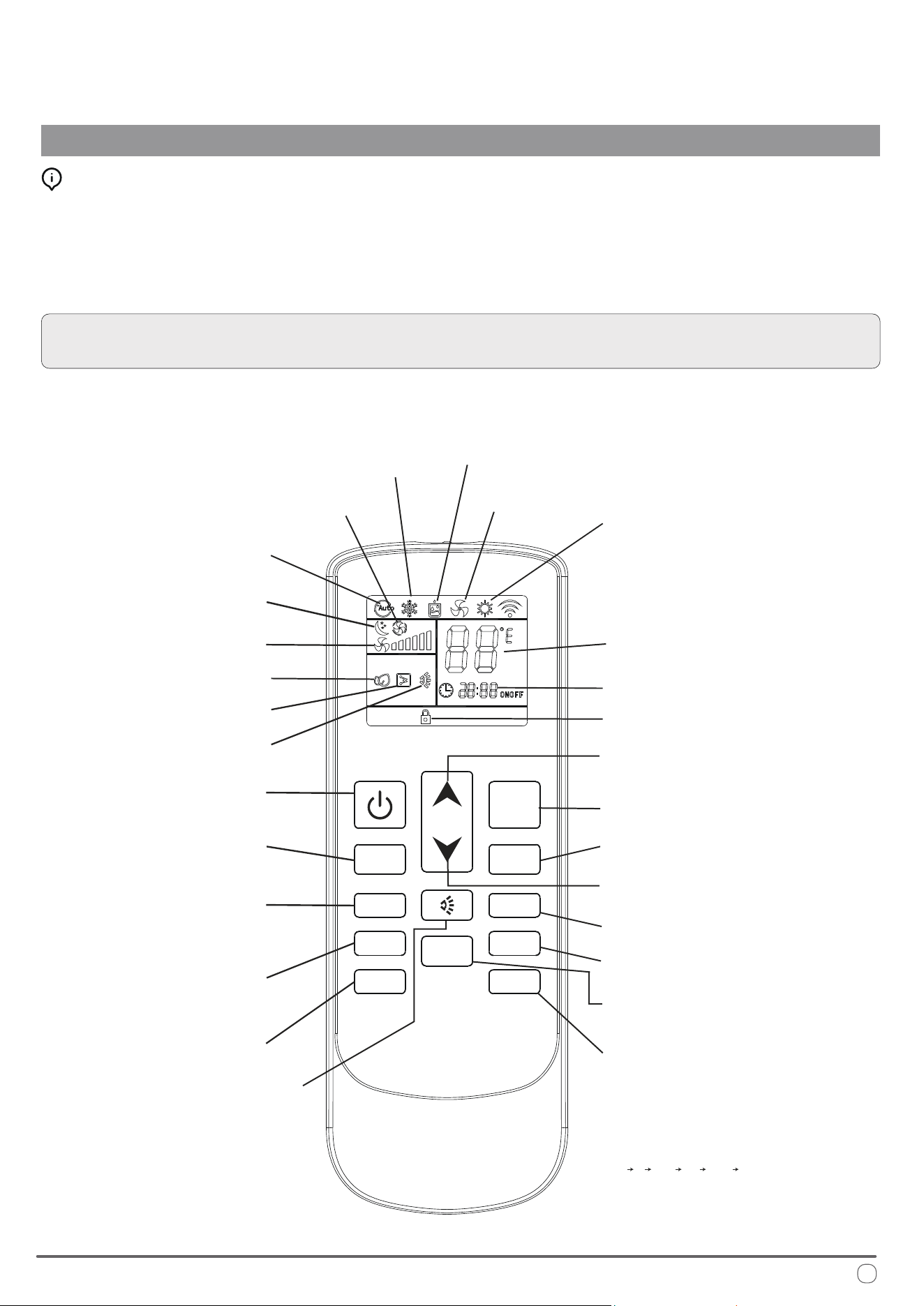
Description of the Controls
OPERATIONAL INSTRUCTIONS
Selecting the Functional Mode:
Press the MODE button to cycle between the available states on the machine.
After two seconds have elapsed, the system will conrm the selection with an
audible beep from the machine’s speaker. Always point the remote controller
toward the control panel when sending commands to ensure the best reception.
NOTE: When rst switching on the system, the machine will stay in standby
mode for a few minutes before the compressor begins operating.
Dehumidication
(Dry) Mode
Ventilation
Mode
Night
Mode
Automatic
Mode
Change Mode
Temperature
Selection (+)
Temperature
Selection (-)
Heat Pump Mode
Clock and Timer
Cooling Mode
Set Point
Fan Speed
On/O
Timer On/O
Clock Conguration
Toggle Celsius
or Fahrenheit
Light and LED Strip
Control Button
In cooling or heating mode, the
operation of the LED strip can be
controlled using the SLEEP button.
e LED strip will cycle continuously
through the following sequence:
"o on white blue yellow o."
Note: e LED strip cannot be
controlled while in dry mode.
(No Current
Function)
Louver Swing
(Function
Unavailable)
FAN- FAN+
MODE
HEATER SLEEP
CLOCK TIMER
LOCK
LIGHT
0
C /
0
F
Lock Indicator
Auto Fan
Lock Toggle
Light*
Electrical Heat*
Airow Direction
Fan Speed (+)
Fan Speed (-)
Sleep Mode
*indicates optional function
11
12
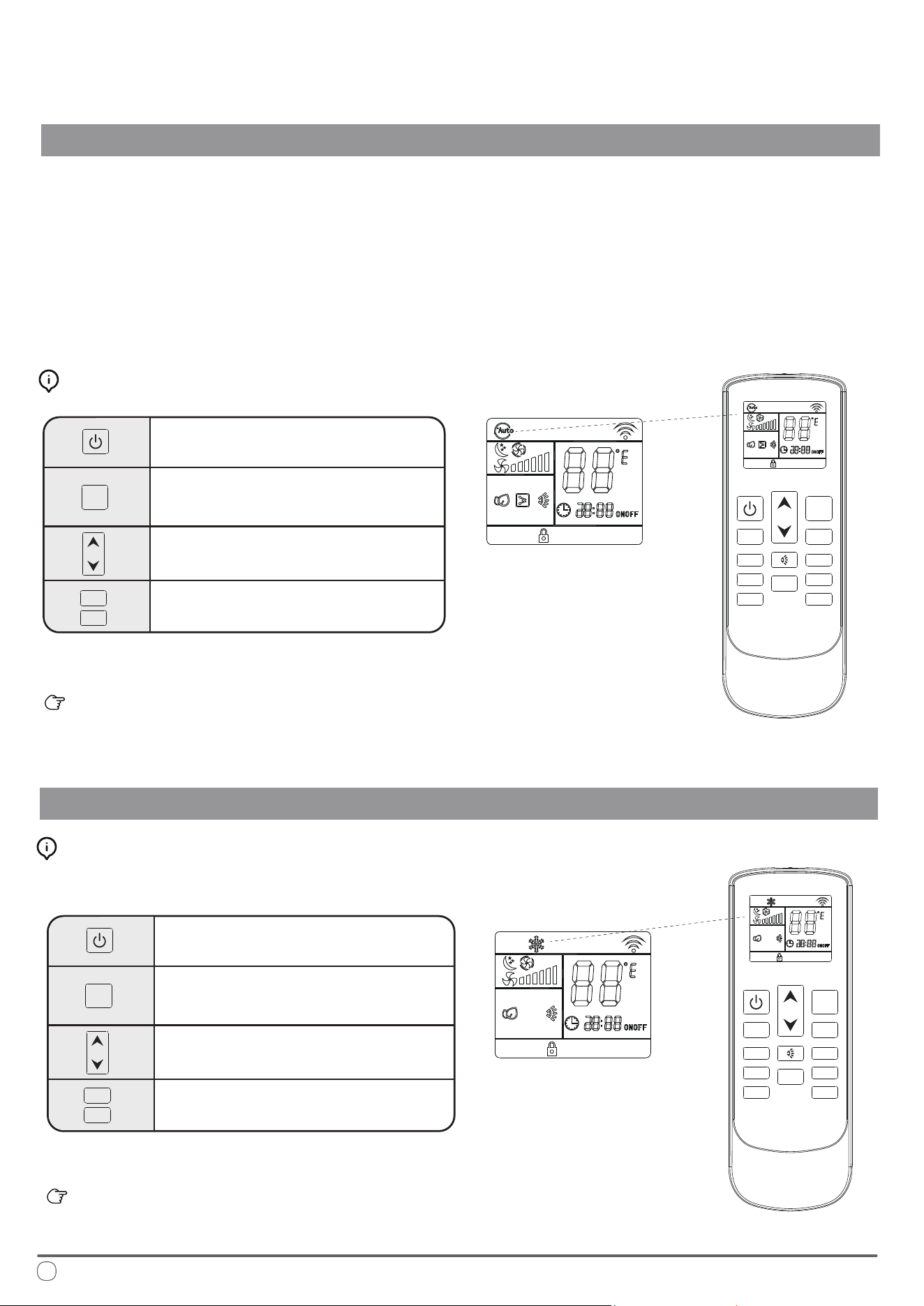
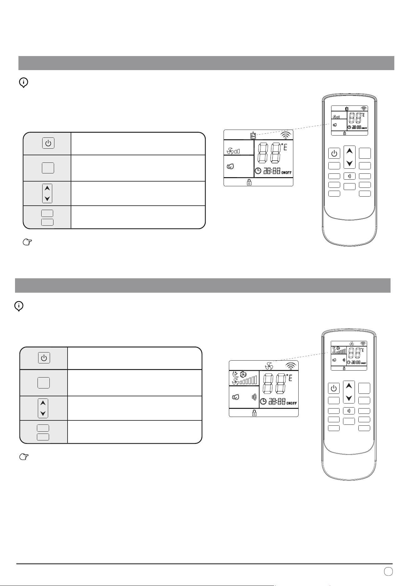
Automatic Mode Operation
OPERATIONAL INSTRUCTIONS
In AUTO mode, the system manages the compressor, heat pump, and fan speeds
entirely autonomously by comparing the set temperature with the current internal
temperature to determine whether to output heating or cooling.
On the AUTO speed setting the ventilation speed is set according to the dierence
in temperature between the set point and the current ambient temperature.
Automatic Mode Button Control:
Press the On/O button to switch the
machine on or o
Press the Change Mode button to
select AUTO mode
Use the temperature selection buttons to
select the desired set point temperature.
Press the fan speed buttons to select low,
medium, high, or automatic fan speed
Cooling Mode Operation
Press the On/O button to switch the
machine on or o
Press the Change Mode button to
select COOL mode
Use the temperature selection buttons to
select the desired set point temperature.
Press the fan speed button to select low,
medium, high, or automatic fan speed
e selected conguration will be retained in the system’s
memory when it is switched on again next.
Cooling Mode Button Control:
Note: Auto Fan speed is determined by the dierence between set and room temperature.
FAN-
FAN-
FAN+
FAN+
MODE
MODE
HEATER SLEEP
CLOCK TIMER
LOCK
LIGHT
FAN-
FAN+
MODE
0
C /
0
F
FAN- FAN+
MODE
HEATER SLEEP
CLOCK TIMER
LOCK
LIGHT
0
C /
0
F
e selected conguration will be retained in the system’s
memory when it is switched on again next.
Note: Auto Fan speed is determined by the dierence between set and room temperature.
is mode cools the room air it draws in and supplies it back into the vehicle.
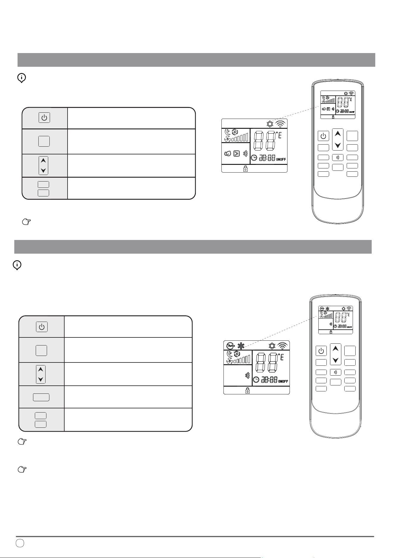
Dehudication Mode Operation
OPERATIONAL INSTRUCTIONS
Press the On/O button to switch the
machine on or o
Press the Change Mode button to
select DEHUDIFICATION mode
Use the temperature selection buttons to
select the desired set point temperature.
Fan speed selection button is disabled
in this mode and will remain low speed.
e selected conguration will be retained in the system’s
memory when it is switched on again next.
Dehumidication Mode Button Control:
Ventilation Mode Operation
Press the On/O button to switch the
machine on or o
Press the Change Mode button to
select VENTILATION mode
Use the temperature selection buttons to
select the desired set point temperature.
Press the fan speed button to select low,
medium, high, or automatic fan speed
e selected conguration will be retained in the system’s
memory when it is switched on again next.
Ventilation Mode Button Control:
Fan-only mode is used to set the system to use only air ventilation
and no heating or cooling.
Dehumidication mode is a limited function that can help reduce
the humidity/moisture of the room. However, this system is not
intended for use as a dedicated dehumidier and so this mode
should not be left running for very long periods of time.
FAN-
FAN+
MODE
FAN-
FAN+
MODE
FAN- FAN+
MODE
HEATER SLEEP
CLOCK
TIMER
LOCK
LIGHT
0
C /
0
F
FAN- FAN+
MODE
HEATER SLEEP
CLOCK
TIMER
LOCK
LIGHT
0
C /
0
F
13
Heat Pump Mode
OPERATIONAL INSTRUCTIONS
Press the On/O button to switch the
machine on or o
Press the Change Mode button to
select HEAT PUMP mode
Use the temperature selection buttons to
select the desired set point temperature.
Press the fan speed button to select low,
medium, high, or automatic speed
e selected conguration will be retained in the system’s
memory when it is switched on again next.
Heating Mode Button Control:
Night Mode Operation
Press the On/O button to switch the
machine on or o
Press the Change Mode button to
select the desired operation mode
Use the temperature selection buttons to
select the desired set point temperature.
e system automatically keeps the fan
speed to low when using this mode
Press the night mode button to turn
this feature on or o
e selected conguration will be retained in the system’s
memory when it is switched on again next.
is mode sets the ventilation on low speed therefore it is
not possible to switch to the other available options.
Night Mode Button Control:
is mode heats the room air it draws in and supplies it back into the vehicle.
Night mode is generally meant for periods of lower comfort
requirements, such as during typical sleeping hours. is mode
will result in decreased energy use, and can only be activated via
remote control.
FAN-
FAN+
FAN-
FAN+
MODE
MODE
FAN- FAN+
MODE
HEATER SLEEP
CLOCK TIMER
LOCK
LIGHT
0
C /
0
F
FAN- FAN+
MODE
HEATER SLEEP
SLEEP
CLOCK TIMER
LOCK
LIGHT
0
C /
0
F
14
Note: Auto Fan speed is determined by the dierence between set and room temperature.
15
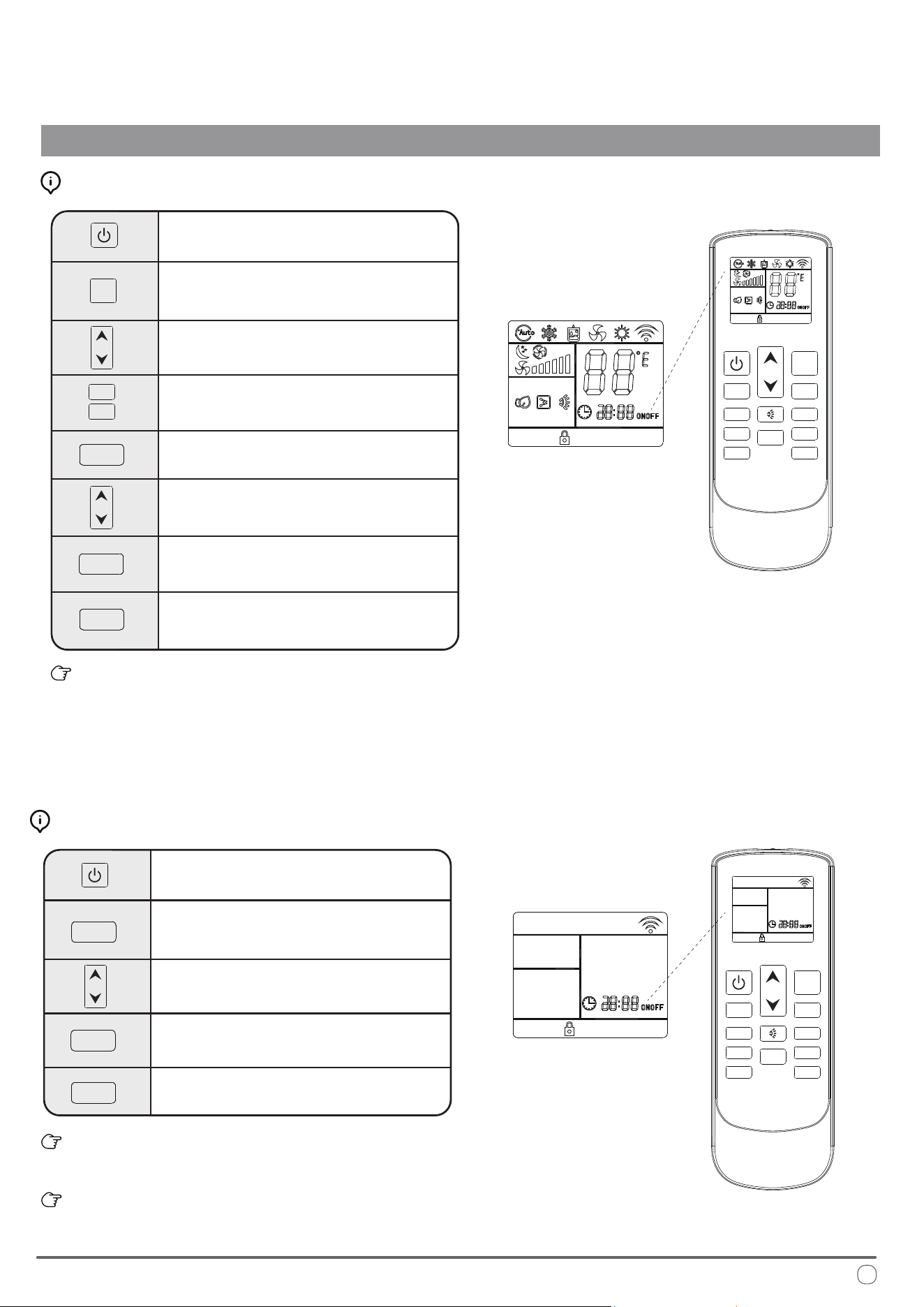
OPERATIONAL INSTRUCTIONS
Timer On and Timer O Mode Operation
Press the On/O button to switch the
machine on
Press the Change Mode button to
select the desired operation mode
Use the temperature selection buttons to
select the desired set point temperature.
Press the fan speed button to select low,
medium, high, or automatic fan speed
Press the Timer button to set the time at
which the system turns itself o
Use the temperature selection buttons to
modify the time value selection
When the Timer O button is rst pressed, the symbol on the
display will be ashing to signify the switch-o feature is being
set. Pressing it once more will conrm the data entered, and the
icon will remain solid to indicate that Timer O is set. Pressing
it a third time deactivates the Timer O function.
How to Congure the Timer O Feature:
e system must currently be o to
congure the Timer On function
Press the Timer button to set the time
at which the system will come on
Use the temperature selection buttons to
modify the time value selection
Use the UP arrow to increment the time value up by 1 hour.
Use the DOWN arrow to increment the time value up by 10 minutes.
e system starts in AUTO mode at time of Timer On activation.
How to Congure the Timer On Feature:
Press the Timer button to conrm
the selections entered
Pressing the Timer button once more
will deactivate the feature
Press the Timer button once more to
conrm the selections entered
Pressing the Timer button for a third
time will deactivate the feature
FAN-
FAN+
MODE
FAN- FAN+
MODE
HEATER SLEEP
CLOCK TIMER
TIMER
TIMER
TIMER
TIMER
TIMER
TIMER
LOCK LIGHT
0
C /
0
F
FAN- FAN+
MODE
HEATER SLEEP
CLOCK
TIMER
LOCK
LIGHT
0
C /
0
F
16
Handling the Remote Controller
OPERATIONAL INSTRUCTIONS
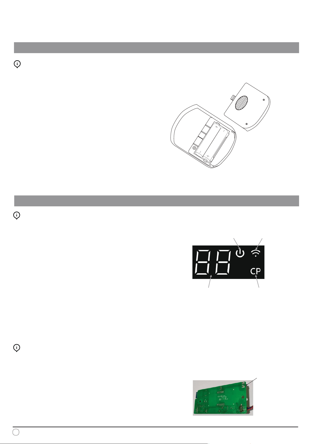
Installing/Changing the Remote Controller Batteries:
Display Panel Indicator Descriptions
Display Panel Buttons and Function Descriptions
1. Remove the rear battery cover.
2. If there are already batteries installed, remove
them and insert two fresh AAA size batteries,
ensuring to pay attention to the direction
of their polarities (+/-).
3. Slide the rear battery cover of the remote
back into place.
4. Check that the remote works properly by
pressing the ON button. If on pressing the
ON button no icon appears on the display,
re-install the batteries and conrm that they
are new and have been placed in the correct
orientation.
5. e system is now ready to be controlled.
• Temperature and Error Code Display: Shows the set
temperature, room temperature, and any error codes.
• Power Light: e power light will illuminate when the
machine is turned on and turn o when the machine is
shut down.
• Compressor Operation Indicator Light: is light
turns on when the compressor is running and turns o
when the compressor stops.
• WIFI Indicator Light: Indicates the status of the WIFI
connection. e light will ash when ready to connect
with a mobile app, and remain on continuously once
the app is successfully connected.
• WIFI Button: Used to enable or disable the WIFI connection.
• Urgency ON/OFF Button: Provides a way to urgently start or
shut down the machine when the remote controller is unavailable.
Power Indicator Wi-Fi Indicator
Compressor
Operation
Indicator
Manual
Operation
Button
Description of the Decorative Panel
Temperature
or Error Code
Indicator
Installation of “Pioneer Airlink” smartphone application
Search for “Pioneer Airlink” in the Google Play Store (for Android users) or the App Store (for iOS users).
Note that a 2.4GHz Wi-Fi connection is needed to use the Wi-Fi control feature.
Or, scan the below QR code to download the app from the respective app store.
Wireless Control App Setup Process
1. Registration and Log-In:
2. Adding a New Device:
Download iOS App
Download Android App
• Approve the “User Agreement” and “Privacy Policy” when they appear by tapping “I Agree”.
• Tap the “Sign Up” button, choose your country, and enter your mobile number/e-mail to register, tick “I
Agree” on “User Agreement and Privacy Policy”, then tap the “Get Verication Code” button. e phone
or e-mail that you’re registering will receive a registration verication code.
• Enter the verication code and select a password. You will then either land on the homepage of the App, or
back to the login interface to log into the app, by using the account you just created.
• Conrm that your phone is connected to Wi-Fi (2.4GHz networks only, 5Ghz will not work).
• Tap the “+” at the top-right corner of the homepage, to enter the device selection page.
• Once you’ve entered this page, head to the RV system and press the "Wind Swing" button on the remote control
ve times within 5 seconds to enter the network distribution mode. On the rst attempt, it will enter slow ash
distribution mode. Press the "Wind Swing" button ve times within 5 seconds again to enter fast ash mode.
• Clearing WIFI Pairing: After successful pairing, press the wind speed button ve times within 5 seconds to clear
the WIFI pairing.
Wi-Fi Connection and Instructions for Usage
OPERATIONAL INSTRUCTIONS
If you do not already have a “Pioneer Airlink” account, please create and account and log-in by following the
below steps:
17
18
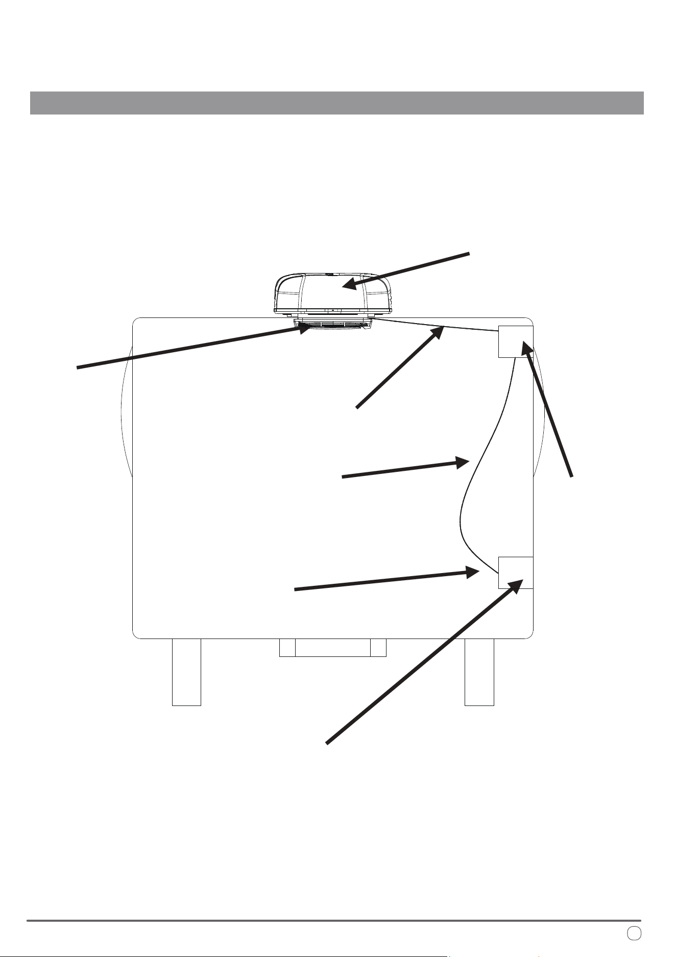
Routine Maintenance
OPERATIONAL INSTRUCTIONS
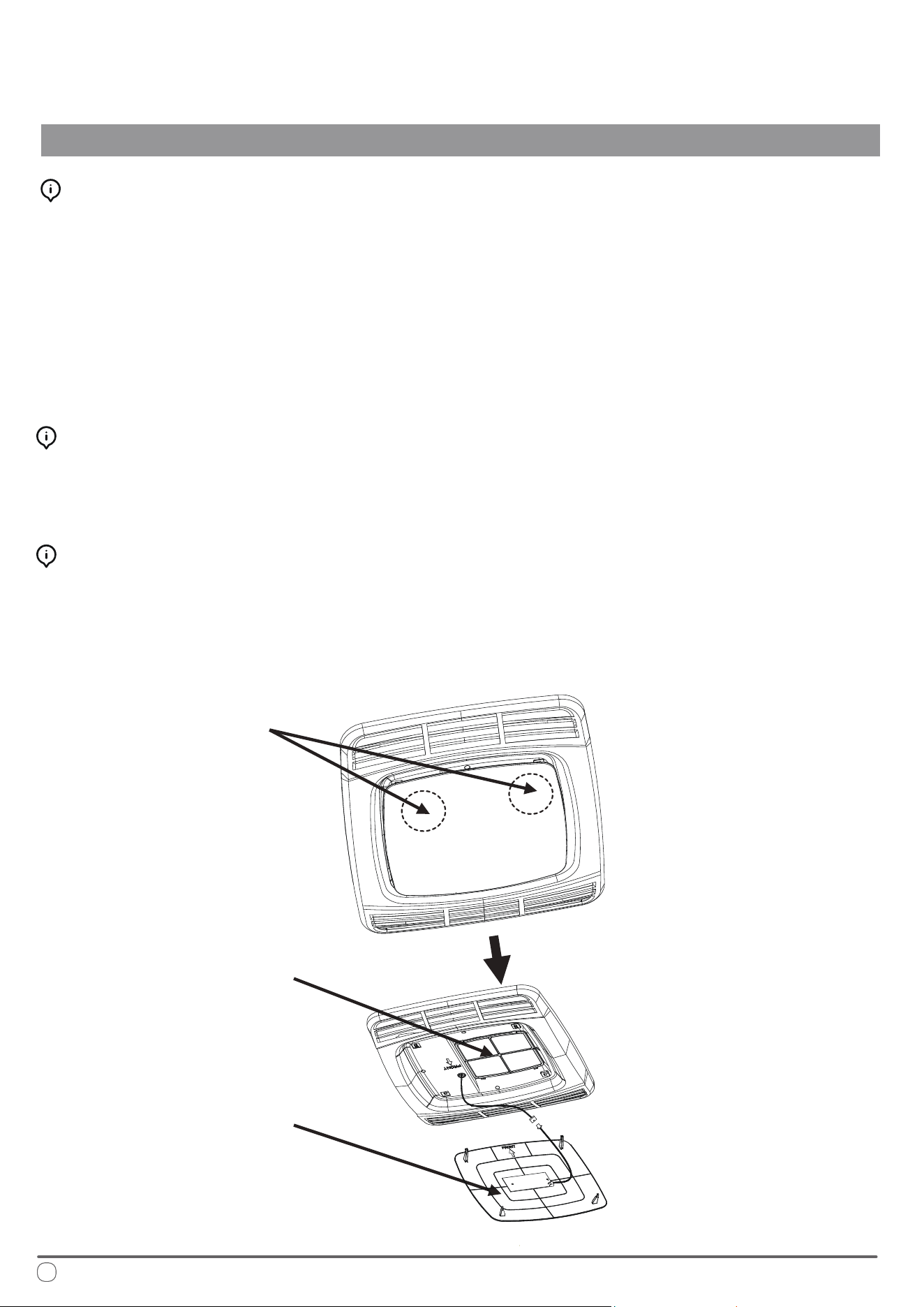
Cleaning the Filter Screen
To clean the lter screen, follow these steps:
1. Locate the left and right buckles of the decorative panel.
2. Press the buckles to remove the decorative panel and access the lter screen behind it.
3. Rinse the lter screen thoroughly with clean water from the reverse side.
4. Allow the lter screen to dry completely before reinstalling it.
Note: Do not operate the air conditioner without the lter screen in place, as this may lead to contamination
of the evaporator coil and negatively impact the air conditioner's service life.
Cleaning the Filter Screen
Use a soft cloth dipped in a neutral detergent to clean the outer surface of the panel.
Avoid using polishing agents or cleaning powders.
Fan Motor Maintenance
e fan motor is pre-lubricated at the factory and does not require special maintenance.
Head direction of the RV
Filter Screen
Position of left and
right buckles of the
decorative panel
Decorative Panel
Getting Started
Installation Positioning
INSTALLATION INSTRUCTIONS
19
Precautions
Please read the installation and operation instructions carefully before installing and using this product.
e manufacturer is not liable for any loss or injury resulting from failure to comply with this manual.
• Installation must adhere to national electrical code regulations or applicable industry standards.
• is product should not be equipped with any additional equipment or accessories without the manufacturer's
authorization.
• Installation and maintenance must be performed by qualied personnel.
is product is designed to be installed on the roof of an RV. When determining your cooling requirements, take
the following factors into consideration:
• Size of the RV: Larger RVs may require more cooling capacity.
• Window Area: A larger window area can result in increased heat inside the RV.
• ickness and ermal Insulation: Consider the thickness and thermal insulation properties of the compartment
walls and roof.
• Geographical Location: e climate and conditions of the location where the RV is used can impact cooling
requirements.
Factors for Installation
is product is intended to be installed on an existing roof
vent. Typically, a 14-1/4" x 14-1/4" ± 1/8" opening will be
available on the roof after the vent is removed.
If there is no vent on the roof, or if this product needs to be
installed in another position, it is recommended to follow
these guidelines:
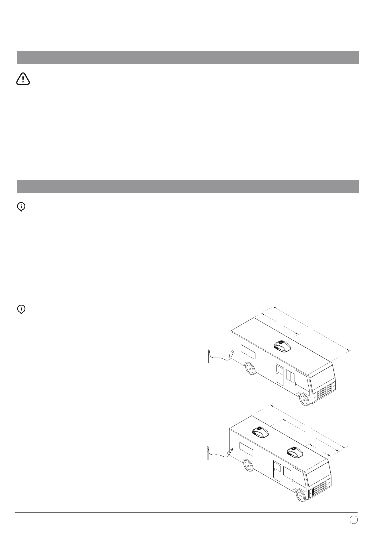
1. When installing a single air conditioner, it should be
positioned slightly ahead of the center point (as viewed
from the front of the vehicle) and centered between the left
and right sides, as shown in the following gure.
2. When installing two air conditioners, they should be
positioned at the 1/3 and 2/3 points from the front end
of the RV, and centered between the left and right sides,
as illustrated in the following gure.
Selection of Installation Position
L
1/2 L
L
2/3 L
1/3 L
For optimal performance, this product should be installed horizontally (assuming the RV is parked on a level
surface) with a maximum allowable gradient of no more than 15°.
Once the installation position is determined, check for any obstacles in the designated area. Ensure that there is a
minimum distance of 18 inches between the back of the vehicle body and any other roof equipment.
When the RV is in motion, the roof must be capable of supporting a load of 135 lbs. Typically, a static load design
of 220 lbs is sucient to meet this requirement.
Additionally, verify that there are no obstacles, such as door openings, partition frames, curtains, or ceiling xtures,
that would interfere with the installation of the inner panel of the air conditioner.
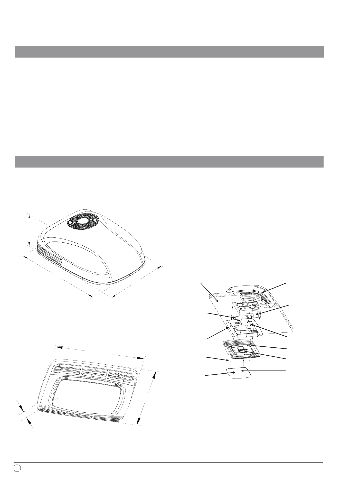
e overall dimensions of the RV rooftop heat pump system and panel are as follows:
Outdoor Unit
10”
41-5/8”
29-1/8”
21-1/4”
19-3/8”
2-7/8”
Guidelines for a Successful Installation
INSTALLATION INSTRUCTIONS
20
Dimensional Information
Control Panel
Installation Exploded Diagram
Roof of RV Outdoor Unit of
Air Conditioner
Control Box
Long Bolt
Screws
Display
Board
Decorative
Panel
Filter Screen
Panel
Fixing Plate
Air Duct
Foam
WARNING
1. Unscrew and remove the screws to detach the vent.
2. Remove all joint llers around the opening.
3. Seal all screw holes and joints on the roof washer using a high-quality, all-weather sealant to ensure a proper seal.
Preparation for Installation
• Mark a 14-1/4" x 14-1/4" ± 1/8" square on the roof and carefully cut out the opening.
• Next, cut a matching hole in the ceiling aligned with the roof opening, as illustrated in the following gure.
Ensure there are no obstacles within a minimum distance of 18 inches from the back of the vehicle body.
is opening must be positioned between the roof reinforcements and extend through both the roof and ceiling of the RV.
• If the opening exceeds 14-3/8" x 14-3/8", liners or llers must be employed to seal the leftover gap.
• If the opening is less than 14-1/8" x 14-1/8", the opening must be enlarged.
Wiring may be present between the roof and ceiling. Before installation, ensure the 115V AC power supply is turned o.
Failure to follow this instruction can result in electric shock, potentially leading to serious injury or death.
Creating a New Roof Opening (Not for Vent Installation)
21
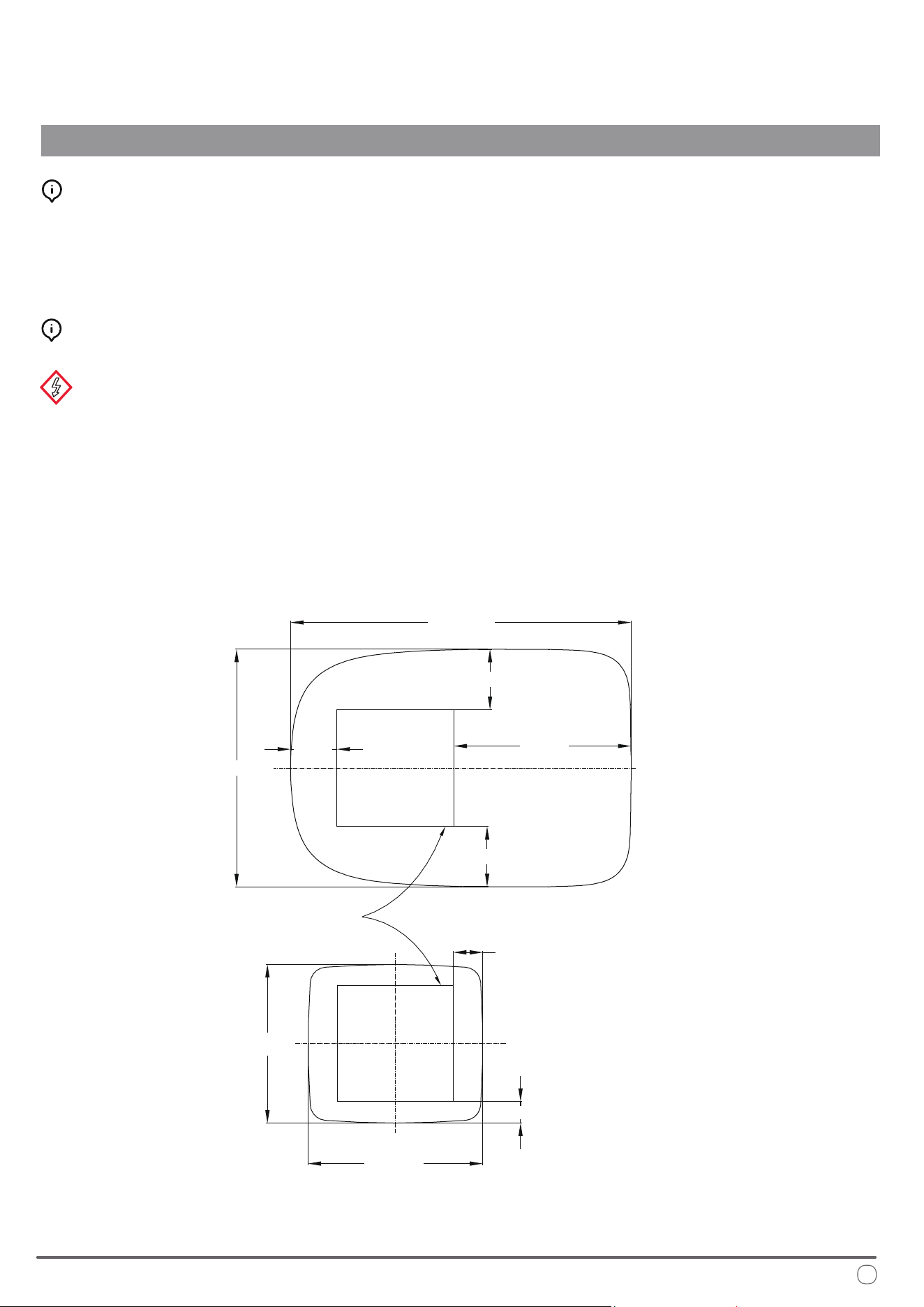
Creation of Roof Opening
INSTALLATION INSTRUCTIONS
41-9/16”
29-1/8”
5-11/16”
21-5/8”
7-3/8”
3-1/2”
2-1/2”
21-1/4”
19-5/16”
Front of the Machine
Opening 14-1/4" x 14-1/4" ± 1/8"
7-3/8”
WARNING
e installation personnel are responsible for ensuring the structural integrity of the RV's roof during air conditioning
installation.
Avoid creating any low-lying areas where water may accumulate on the roof, as stagnant water can seep into the vehicle
and potentially cause damage to both the air conditioning unit and the RV.
Electrical Setup
INSTALLATION INSTRUCTIONS
22
• All wiring methods must comply with all applicable national and local electrical regulations.
• A fuse or circuit breaker should be installed, and proper grounding must be ensured. Extend a eld-supplied
12 AWG copper cable from the circuit breaker to the front position of the roof opening.
▪ e power line must be on a dedicated 20A time delay circuit breaker.
• Ensure the wire extends at least 15 inches into the roof opening to facilitate the installation of the main air
conditioning unit.
• If the existing wire from the removed ventilator is of an appropriate size and the fuse specication is suitable, it
may be reused.
• Use appropriate conduit for protecting any wires entering the opening to prevent damage.
Wiring Requirements
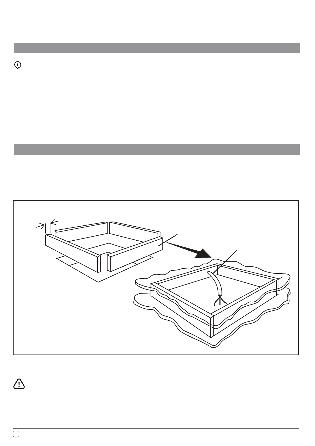
e opening must be properly supported, and the roof interlayer should be lled with insulating materials.
To prevent resonance caused by air within the upper interlayer, seal the perimeter using battens or insulating strips
that are at least 3/4 inch thick.
Additionally, provide an entry point for the power line, as illustrated in the following gure:
e 14-1/4" x 14-1/4" ± 1/8" roof opening forms an integral part of the return air duct, and must be smoothened
and nished in accordance with industry standards.
Opening Treatment
Minimum 3/4"
Frame opening
Provide a Wire Inlet
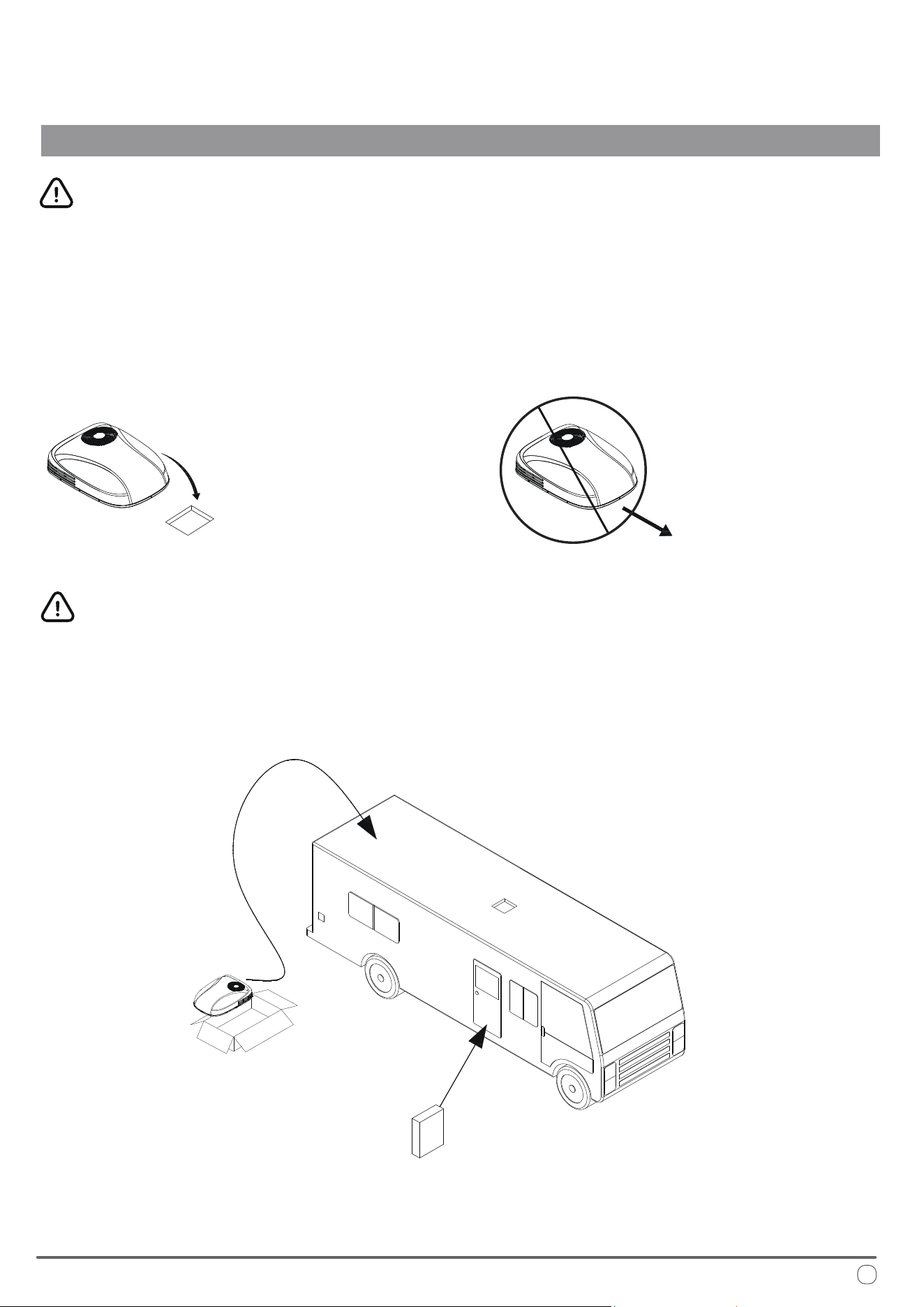
1. Remove the outdoor unit of the air conditioner from the carton.
2. Carefully place the outdoor unit on the roof of the RV.
3. Lift the equipment—do not drag it—by using the box sponge of the air conditioner, and position it over the
prepared opening, with the condenser coil facing the rear of the RV, as illustrated in the following gure:
Next, install the panel assembly inside the RV. e panel assembly includes fasteners designed for securing the air
conditioner, which will be used during installation, as illustrated in the following gure.
If any misalignment is found with the outdoor unit's positioning on the roof during panel installation, the outdoor
unit can be adjusted from inside through the mounting hole. Ensure that the bottom part’s insulation on the roof is
precisely aligned with the 14-1/4" x 14-1/4" square opening.
WARNING
Dragging the air conditioner is strictly prohibited, as it can damage the insulation at the bottom.
Doing so may lead to water leakage due to improper sealing of the insulation after installation.
23
Placement of Air Conditioner Onto Roof
INSTALLATION INSTRUCTIONS
Precaution
Variants of this machine can weigh up to 100 pounds. To prevent unintentional damage to the equipment, it is
highly recommended to use a crane or lifting device to raise the system onto the roof of the RV.
Dragging or sliding
is forbidden
Front of RV
Placement after lifting
*Recycle All Cardboard Packaging Upon Completion
24
Interior Mounting and Connections
INSTALLATION INSTRUCTIONS
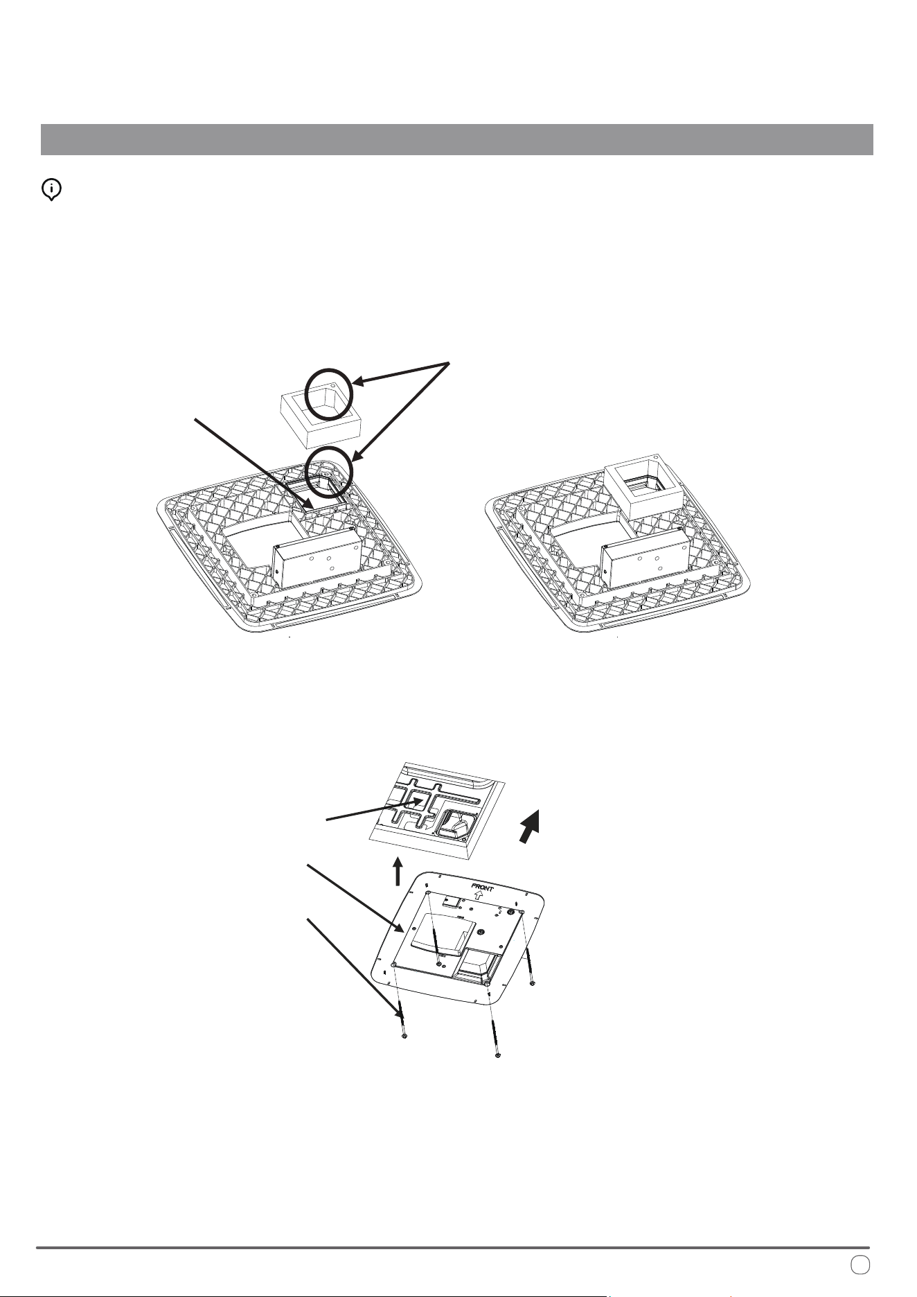
1. Remove the panel and installation accessories from the carton.
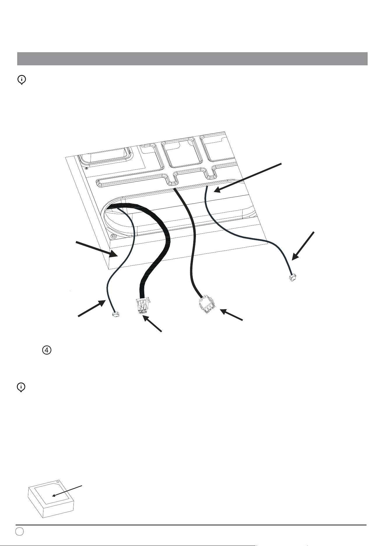
2. Reach through the return air inlet of the air conditioner and pull down the wire harness of the outdoor unit
(for heat pump models, this also includes the four-way valve connecting wire and sensor lead) to facilitate
subsequent connections, as illustrated in the following gure:
Installation of Air Duct and Top Mounting Plate
Measure the width from the ceiling to the roof and select the appropriate air duct foam thickness based on the
following guidelines:
1. For a width of 2.5 - 3cm, use an air duct foam with a thickness of 1.5cm.
2. For a width of 3 - 4
.5cm, use an air duct foam with a thickness of 3cm.
3. For a width of 4 - 6cm, use an air duct foam with a thickness of 4.5cm.
4. If the width is greater than 6cm, combine air duct foams of 15, 30, and 4.5cm thicknesses as needed based on
the actual situation.
5. For a distance greater than 10cm, a field-supplied pipe joint should be used.
Preparation of Air Duct Foam
Return Air Inlet
of Air Conditioner
Wire Harness of
Indoor Unit Fan Motor
Ceiling
Width
Communication Line
(to be connected
with on Page 27)
Power Wire Harness
of Outdoor Unit
Anti-Freezing Sensor
Chassis of the outdoor unit of the air conditioner.
e foam in the middle part should be removed during installation.
Installation of Air Duct Foam
INSTALLATION INSTRUCTIONS
25
Note: Middle portion of air duct foam is intended to prevent deformation and should be removed during installation.
Select the appropriate air duct foam thickness, remove the middle portion, and ax it to the xing plate along the
air outlet. Ensure that the holes on the foam align with the holes on the fastening plate, as illustrated in the
following gure:
Align the arrow on the fastening plate toward the front of the RV, position the plate over the 14-1/4" x 14-1/4"
ceiling opening, and secure it to the outdoor unit of air conditioner on the roof using four bolts of suitable length.
Note: Before fully tightening the bolts, begin by screwing each bolt in by hand. e four rivet nuts on the chassis of the
outdoor unit are located at the corners of the opening. Insert and hand-tighten the four long bolts into the corresponding
rivet nuts. Once all bolts are in place, tighten them evenly, one at a time, with a torque of 3.3 ft·lbs to 4 ft·lbs.
is will compress the box foam on the roof to a thickness of approximately 1/2". ese bolts are self-locking, so excessive
tightening is not necessary.
If the bolts are too loose, the roof may not be adequately sealed. Conversely, overtightening the bolts could cause damage to
the air conditioner chassis or the xing plate. Tighten the bolts according to the torque specications provided above.
A
ir Duct Foam (Available in Three Thicknesses: 1.5, 3, and 4.5cm)
Air Outlet
The through hole of air duct foam
should correspond to the hole on
the fastening plate
Chassis of the
Outdoor Unit of
Air Conditioner
Head Direction
Fastening Plate
Threaded Bolt (4)
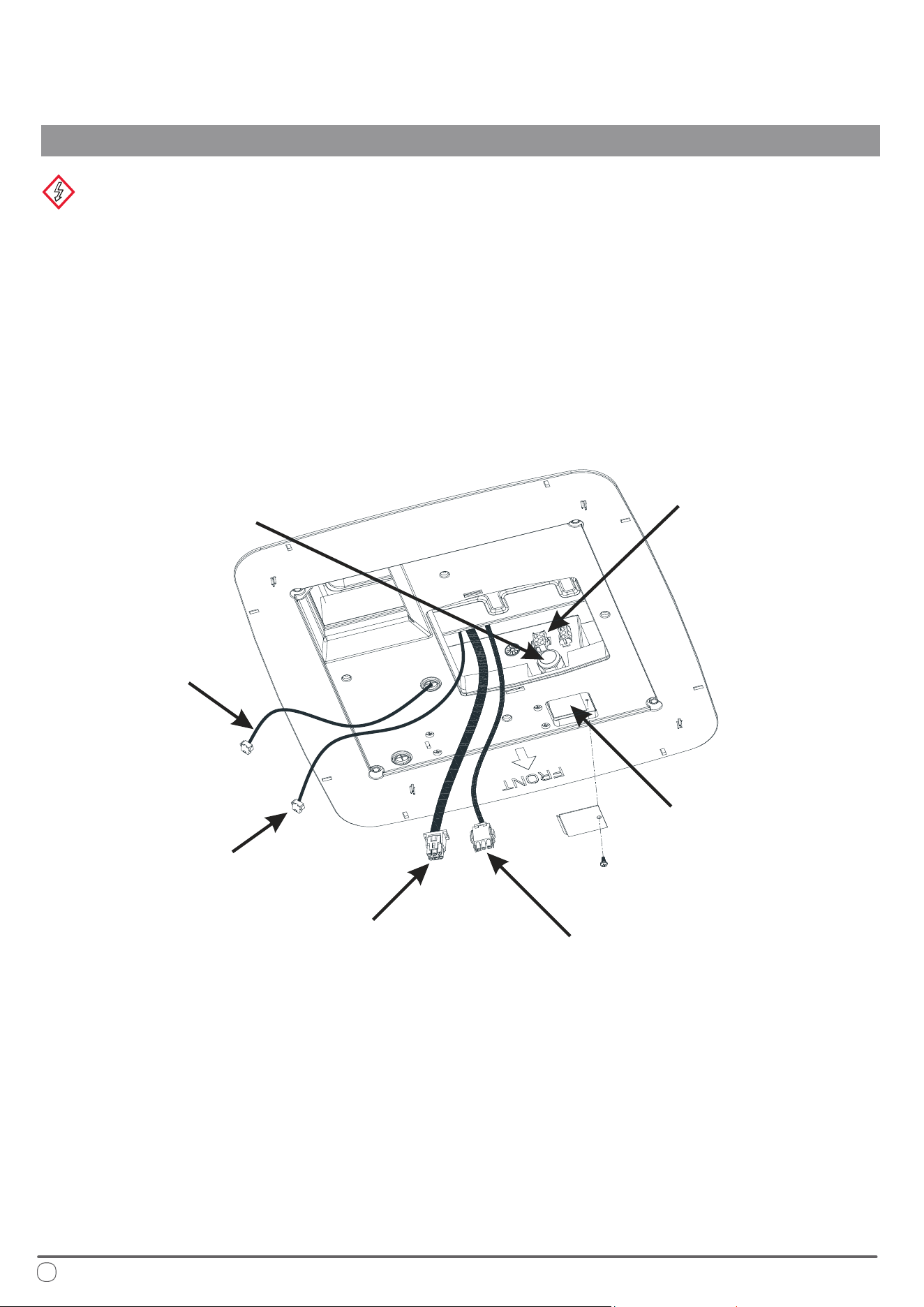
First, remove the maintenance plate covering the maintenance port of the control box. Feed the main power line
(approximately 6 inches long) into the control box through the cable stub. Secure the cable stub to prevent the main
power line from being pulled, which could lead to loose connections.
Connect the wires as follows:
• e white wire in the control box should be connected to the white wire (neutral wire) of the main power line.
• e black wire should be connected to the black wire (live wire) of the main power line.
• e yellow-green wire should be connected to the yellow-green wire (ground wire) of the main power line.
Use specialized wiring connectors for fastening these wires, ensuring they are well-secured and rmly in place.
Interior Underside View of Air Conditioner
26
Electrical Wiring
INSTALLATION INSTRUCTIONS
WARNING
Disconnect the main power supply before performing any work. Failure to comply with this instruction can result in
electric shock, leading to serious injury or death.
e air conditioning equipment must be properly grounded to prevent electric shock hazards. Ensure that the equipment
is connected to a 115V/60Hz circuit with reliable grounding. Failure to follow these instructions may result in death,
injury, or equipment damage.
Electrical installation must be performed by qualied professionals, and all wiring must comply with national electrical
codes and industry standards.
Communication Line
Wire harness of
indoor fan motor
Power Wire Harness of
Outdoor Unit
Maintenance Port
of Control Box
Corresponding
Terminal of
Control Box
Cable Stub of Control Box,
from which the Main Power
Line will be Introduced
Connecting Wire
of Display Panel
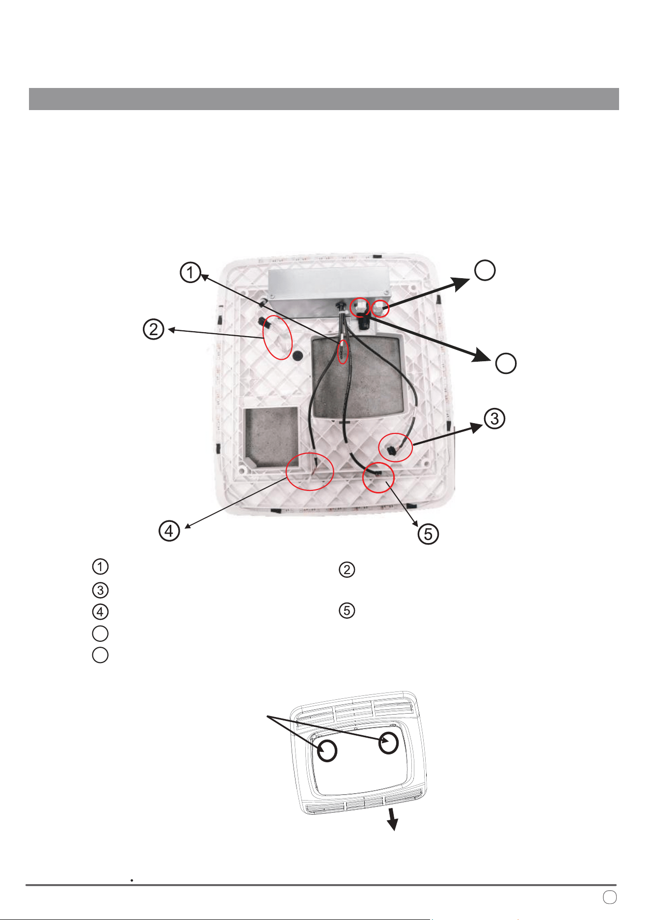
Place the connected wires back into the maintenance port of the control box and reattach the maintenance plate.
Insert the outdoor unit’s plug-in wire harness, which was pulled out from the return air outlet of the air conditioner,
into the corresponding six-core terminal plug of the control box. (For heat pump or electric heating models, the
three-core plug from the return air outlet should be inserted into the corresponding three-core terminal plug.)
Ensure all plug-in terminals are properly seated.
Connect the remaining plug-in wires on the control box as follows:
System Connections
INSTALLATION INSTRUCTIONS
27
Indoor Temp Sensor;
LED Strip Wire;
Connecting Wire of Display Panel;
Communication Line;
Anti-Freezing Sensor
Wire Harness of Electric Heater
Power Wire Harness of Outdoor Unit
6
7
6
7
Left and right buckles
on the decorative panel
Arrow direction on the panel
(vehicle head direction)
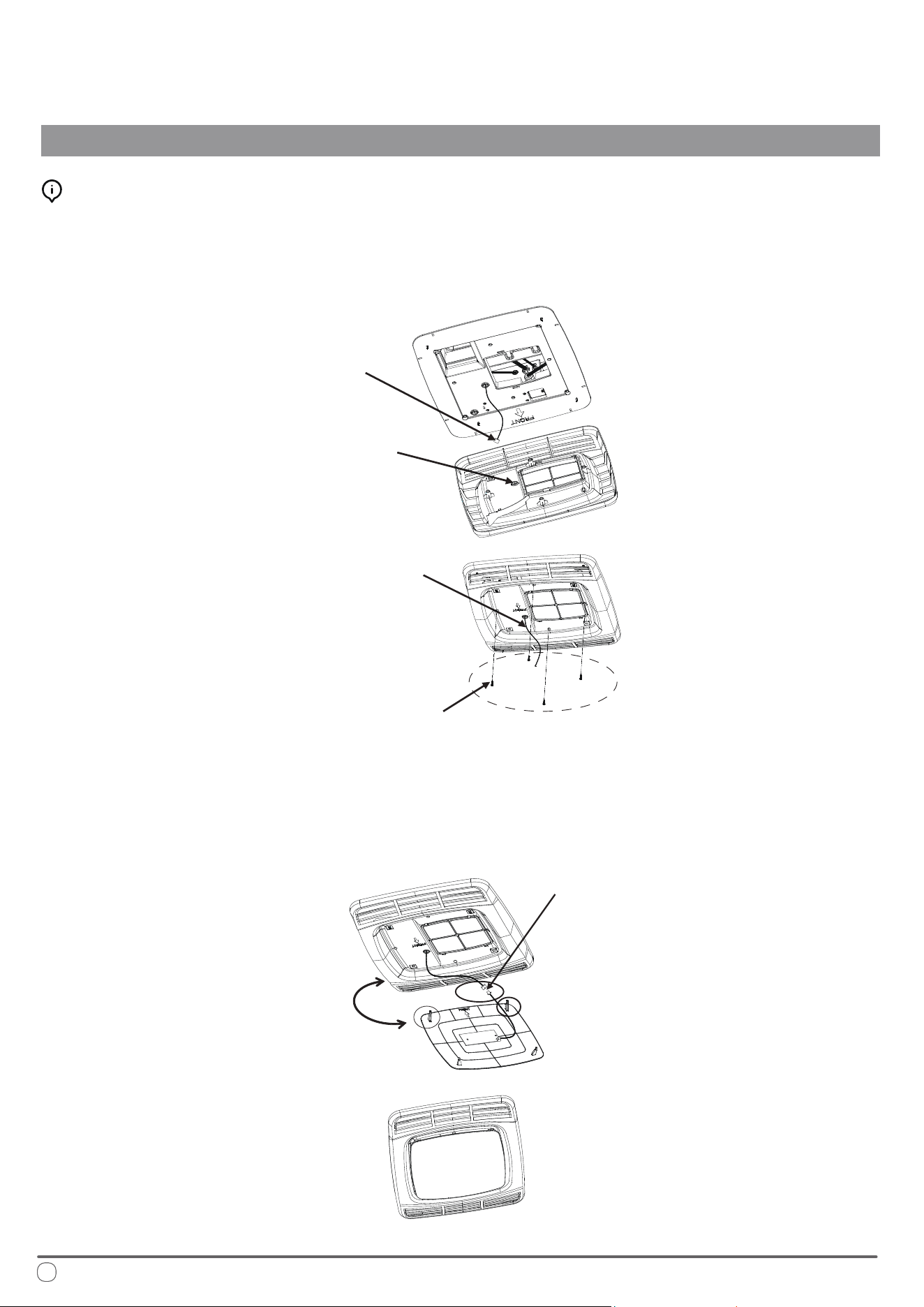
Remove the panel and align it according to the directional indicators on the panel. Pass the display panel's connect-
ing wire from the control box through the via hole on the panel. Attach the panel to the xing plate and secure it
tightly using four screws, as illustrated in the following gure:
Take out the decorative panel, and with the arrow direction facing the head of RV, plug the connecting wire of
display lamp board with the connecting wire of display lamp board of the decorative panel in place, and then install
the lamp board on the panel (when installing the decorative panel, rst clamp the two buckles in arrow direction on
the corresponding holes of the panel, and then clamp the rear two buckles on the panel lock), as shown in the
following gure:
28
Mounting the Panel
INSTALLATION INSTRUCTIONS
Alignment and Connection
Connecting Wire
of Display Lamp Board
Pass-through Hole
of the Panel
Screw (4)
Connecting Wire of
Display Lamp Board
Plugging of
Connecting Wire
of Display Lamp Board
Corresponding
Buckles
Initialization of System
INSTALLATION INSTRUCTIONS
29
After the air conditioning equipment is installed, turn on the power supply to perform a running inspection.
Be sure to read the operation instructions thoroughly before proceeding with further operation.
e permanent wiring for the air conditioning control box can be connected from the main incoming line of the
RV, which is routed along the side wall, as illustrated in the following gure.
A dedicated socket for the air conditioning equipment should be installed on the side wall of the RV.
e cable must be connected to both the socket and the fuse.
e main connecting cable should be resistant to oil, water, and ozone corrosion.
Panel
Air Conditioner
Main Cable
Preventive Wiring (Trunking)
Special Plug
Junction Box
It's forbidden to insert other plugs into this circuit
*System lock if occurring 6 times within 20 min.
Switch the system off/on to clear this error code.
30
Troubleshooting
Error Code Interpretation
DIAGNOSTICS, TECHNICAL CHARACTERISTICS, RECYCLING
If the air conditioning equipment is not functioning properly, please perform the following checks to troubleshoot
the issue:
• Verify that the fuse for the air conditioning equipment or the RV’s leakage circuit breaker is turned on.
If the air conditioner is powered by a generator, check whether:
• e generator's power output matches the air conditioner's requirements.
• e generator is operating correctly and producing electricity.
• e generator's voltage output is stable.
If the RV is connected to the main power supply, ensure that:
• e power line specications are suitable for the air conditioner’s operating load.
• ere is an active power supply.
• e mains voltage meets the required specications (operating voltage for the air conditioner is 115V).
• Check that all air conditioner connecting wires are properly inserted and in good condition.
If the air conditioner still does not operate correctly after these checks, please contact the manufacturer for further
assistance.
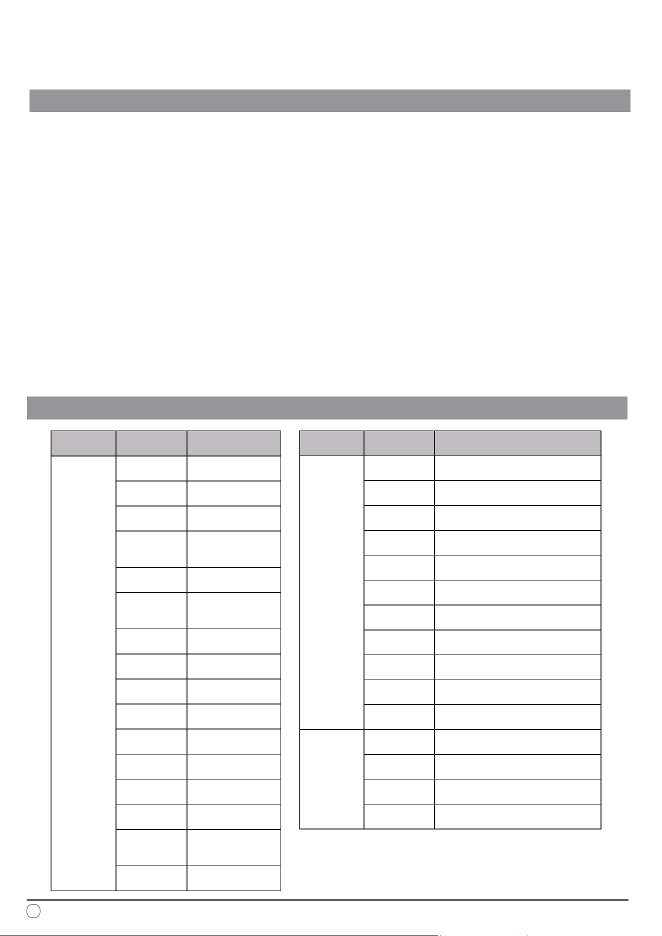
Error Type Error Code Cause of Error
Fault
EE
Indoor Unit
EEPROM
E3
Indoor Coil
Temperature Sensor
E4
Indoor Ambient
Temp Sensor
E7
Outdoor Unit Board
and/or Drive Board
Communication
E0
Outdoor Unit
EEPROM
E6
Main Board and
Drive Board
communication
F1*
Abnormal
Compressor Startup
F2*
Compressor
Out of Step
F3 IPM Module
F5
Discharge
Temperature Sensor
F6
Suction
Temperature Sensor
F7
Outdoor Coil
Temperature Sensor
F8
Outdoor Ambient
Temperature Sensor
F9
Outdoor DC Fan
Motor
E9
Display Board and
Main Board
Communication
Er
Wrong Model
Selection
Error Type Error Code Cause of Error
Protection
P1
Outdoor Unit
Current Overload
P2
Compressor
Phase Current
P3
Outdoor Unit
Over/Under-Voltage
P4
DC Busbar
Over/Under-Voltage
P5
IPM Over
Temperature
P6 Discharge Temp Overheating
P7
Anti-Freezing Protection for Indoor
Coil When Cooling
P8
Overheating Protection for
Outdoor Coil When Cooling
P9
Overheating Protection for
Indoor Coil When Heating
PC
Outdoor Ambient Low
Temperature Protection When Cooling
PH
Outdoor Ambient High Temperature
Protection When Heating
Drive
L1*
Over-Voltage
Protection of Busbar
L2*
Under-Voltage
Protection of Busbar
L3*
Over Current
Protection of Phase
L4* Abnormal Phase Current Sampling
Technical System Information
DIAGNOSTICS, TECHNICAL CHARACTERISTICS, RECYCLING
31
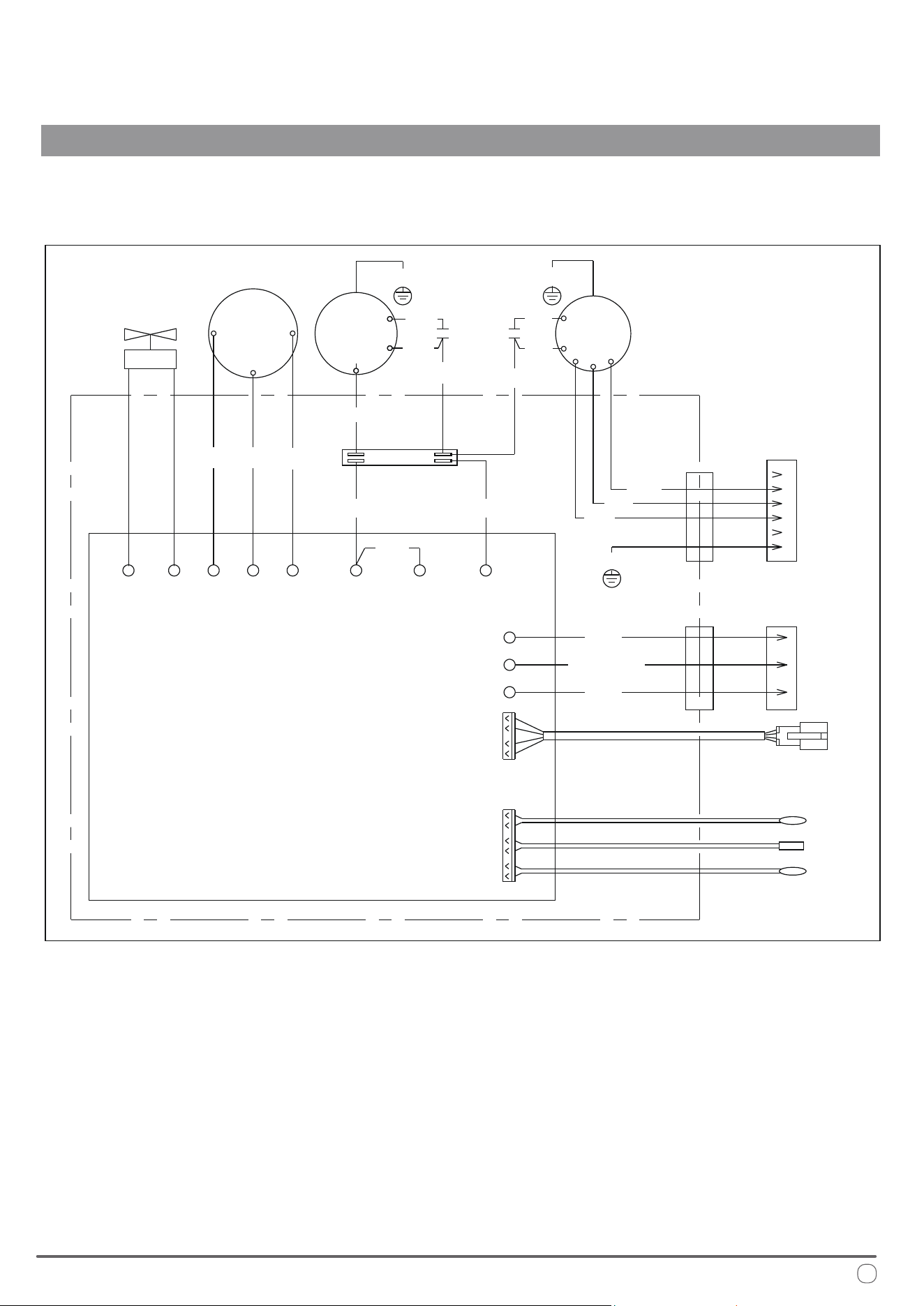
WIRING DIAGRAM
COMPRESSOR
OUTDOOR
MOTOR
TERMINAL
BLOCK
INDOOR
MOTOR
COMMUNICATION
WIRE
U
4WAY CN6
CN10
CN4
AC-N
OFAN-H OFAN-H OFAN-N
GROUND
AC-L
OUTDOOR
SENSOR
CONN. TO AIR DISTRIBUTION BOX
(USE COPPER CONDUCTORS ONLY)
OUTDOOR COIL
SENSOR
EXHAUST
SENSOR
U
W
W
MAIN
CONTROL
BOARD
BRN
BRN
BRN
BLK
BLU
1
1
2
3
4
5
6
2
3
BLU
BLK
BLK
BLK
YEL
RED
CAP CAP
WHT
WHT
WHT
WHT
WHT BLU RED
GRN/YEL
GRN/YEL
GRN/YEL
GRN/YEL
6PIN CONN.
3PIN CONN.
V
V
4-WAY
VALVE
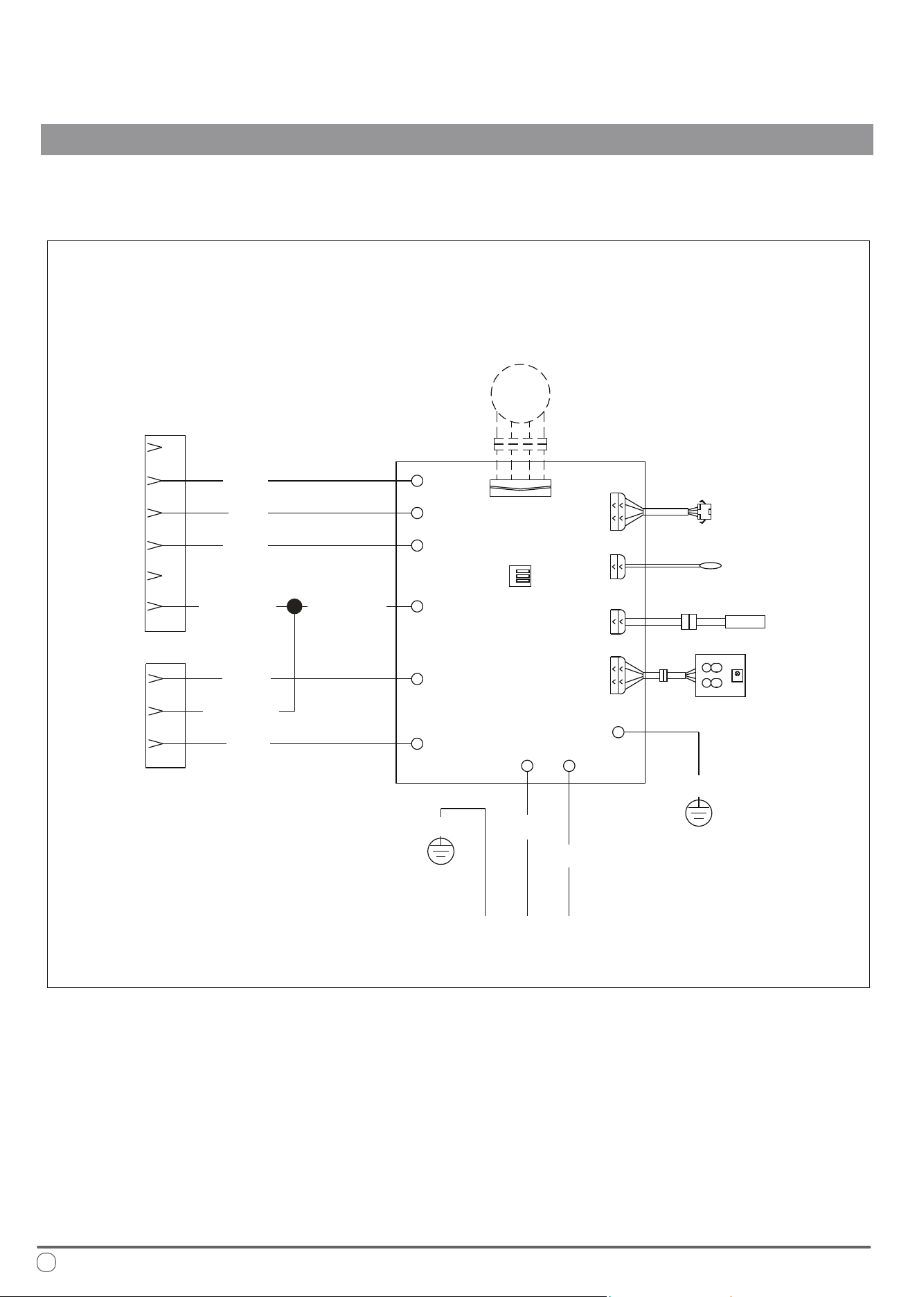
32
RGB
LED
MAIN
CONTROL
BOARD
LINE VOLTAGE
COMMUNICATION WIRE
ROOM SENSOR
GRN/YEL
GRN/YEL
GRN/YEL
GRN/YEL GRN/YEL
RED
YEL
FAN-H
FAN-M
FAN-L
AC-N
AC-N
AC-L
AC-L
E1
CN2
CN1
CN14
CN13
CN5
E1
CN19
BLK
CONN.
CONN.
BLK
BLK
WHT
WHT
FREEZE
SENSOR
DISPLAY
PCB
LED
OPTIONAL*
TO UPPER UNIT TO UPPER UNIT
Technical System Information
DIAGNOSTICS, TECHNICAL CHARACTERISTICS, RECYCLING
DIGITAL CONTROL
European Disposal Guidelines
is appliance contains refrigerant and other potentially hazardous materials. When disposing of this
appliance, the law requires special collection and treatment. Do not dispose of this product as household
waste or unsorted municipal waste.
When disposing of this appliance, you have the following options:
• Dispose of the appliance at a designated municipal electronic waste collection facility.
• When buying a new appliance, the retailer takes back the old appliance free of charge.
• e manufacturer takes back the old appliance free of charge.
• Sell the appliance to certied scrap metal dealers.
Special Notice
Disposing of this appliance improperly, or in other natural surroundings, endangers your health
and is bad for the environment. Hazardous substances may leak into the ground water and enter
the food chain. Please follow proper disposal protocol.
DIAGNOSTICS, TECHNICAL CHARACTERISTICS, RECYCLING
33

e design and specications of this product are subject to change without prior notice
as development continues. Consult with the sales agency or manufacturer for details.
Refer to the equipment nameplate for all other applicable specications.
is a registered trademark of Parker Davis HVAC International
Parker Davis HVAC International
7290 NW 77th Court, Miami, FL 33166 - USA
Tel : (305) 513-4488
Fax : (305) 513-4499
E-mail : [email protected]
Website : www.pdhvac.com
Pioneer product line, parts, and supplies are
available online for convenient ordering at:
www.highseer.com
www.pioneerminisplit.com
Scan the below code to visit our support page
where you can nd more installation materials:
Copyright 2025, Parker Davis HVAC International - All rights reserved.