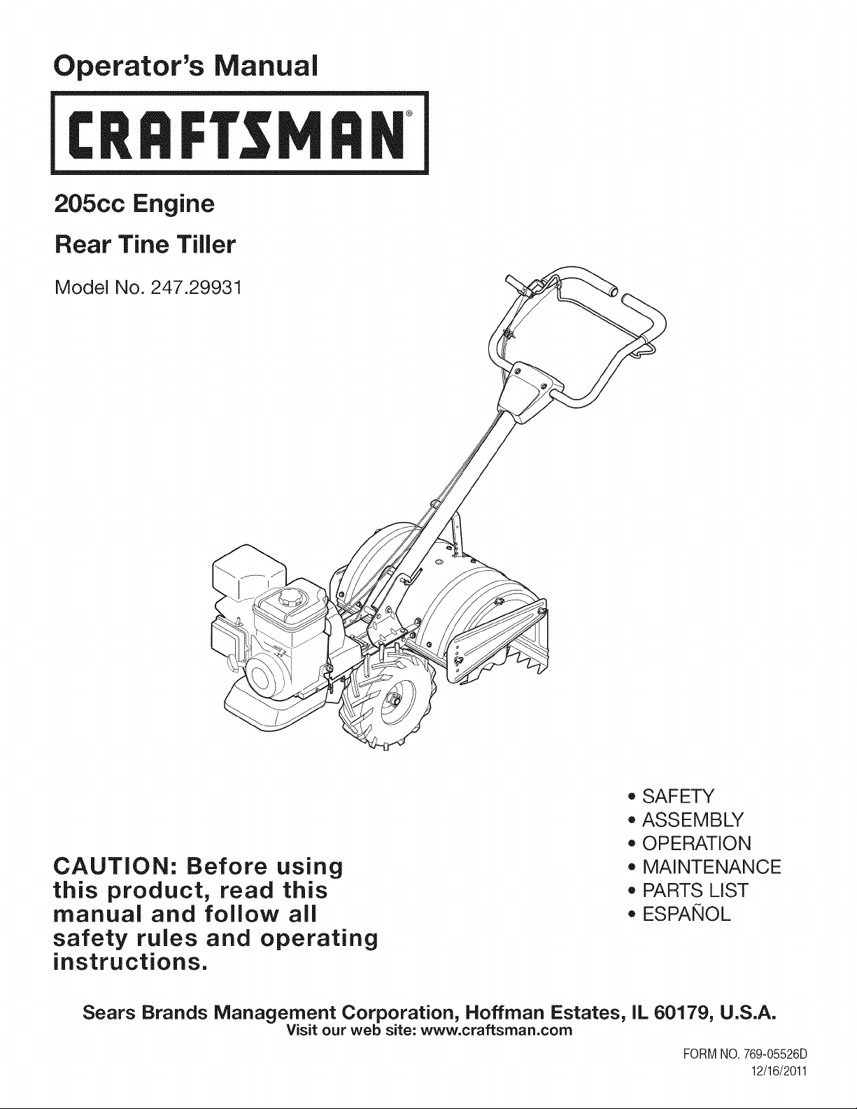
Operator's Manual
I:Rl FI'SlVl N
205cc Engine
Rear Tine Tiller
Model No. 247.29931
CAUTION: Before using
this product, read this
manual and follow aJl
safety rules and operating
instructions.
*SAFETY
*ASSEMBLY
*OPERATION
*MAINTENANCE
*PARTS LIST
*ESPANOL
Sears Brands Management Corporation, Hoffman Estates, IL 60179, U.S.A.
Visit our web site: www.craftsman.com
FORMNO.769-05526D
12/16/2011
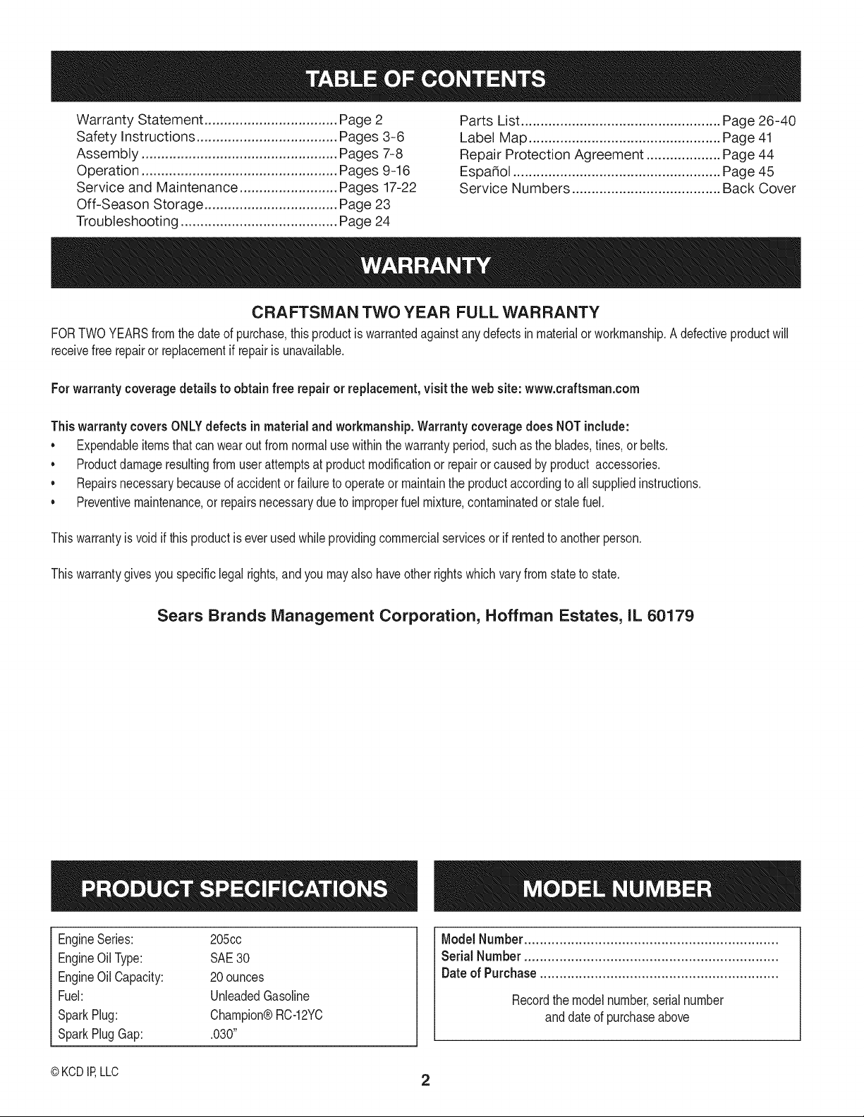
WarrantyStatement..................................Pac
Safetyinstructions....................................Pac
Assembly..................................................Pac
Operation..................................................Pac
ServiceandMaintenance.........................Pac
Off-SeasonStorage..................................Pac
Troubleshooting........................................Pac
e2
es3-6
es7-8
es9-16
es17-22
e23
e24
PartsList...................................................Page26-40
LabelMap.................................................Page41
RepairProtectionAgreement...................Page44
Espa_ol.....................................................Page45
ServiceNumbers......................................BackCover
CRAFTSMAN TWO YEAR FULL WARRANTY
FORTWOYEARSfromthe dateof purchase,this productis warrantedagainstanydefectsin materialor workmanship,A defectiveproductwill
receivefree repairor replacementif repairis unavailable,
For warranty coverage details to obtain free repairor replacement,visit the web site: www.craftsman.com
This warranty covers ONLYdefects in material andworkmanship. Warranty coverage does NOT include:
• Expendableitemsthatcan wearoutfromnormalusewithinthewarrantyperiod,such as the blades,tines, or belts.
• Productdamageresultingfrom userattemptsat productmodificationor repairor caused by productaccessories.
• Repairsnecessarybecauseof accidentor failureto operateor maintainthe productaccordingto all suppliedinstructions.
• Preventivemaintenance,or repairsnecessarydueto improperfuel mixture,contaminatedor stalefuel.
Thiswarrantyis void if thisproductis everusedwhile providingcommercialservicesor if rentedto anotherperson.
Thiswarrantygivesyou specificlegalrights,andyou mayalso haveotherrights whichvary from stateto state.
Sears Brands Management Corporation, Hoffman Estates, IL 60179
EngineSeries: 205cc
EngineOilType: SAE30
EngineOilCapacity: 20ounces
Fuel: UnleadedGasoline
SparkPlug: Champion®RC-12YC
SparkPlugGap: .030"
ModelNumber.................................................................
Serial Number .................................................................
Dateof Purchase.............................................................
Recordthe modelnumber,serialnumber
anddateof purchaseabove
© KCD IP,LLC 2
Thissymbolpointsout importantsafetyinstructionswhich,if not
followed,couldendangerthe personalsafetyand/orpropertyof
yourselfandothers. Readandfollowall instructionsin this manual
beforeattemptingto operatethis machine.Failureto complywith
theseinstructionsmay resultin personalinjury.Whenyou seethis
symbol,HEEDITSWARNING!
CALIFORNIA PROPOSITION 65
EngineExhaust,someof itsconstituents,andcertainvehicle
componentscontainoremitchemicalsknownto Stateof California
to causecancerandbirthdefects or other reproductiveharm.Bat-
tery posts,terminals,andrelatedaccessoriescontainleadand lead
compounds,chemicalsknownto the Stateof Californiato cause
cancerandreproductiveharm.Washhandsafterhandling.
Thismachinewasbuilt to beoperatedaccordingto the safeopera-
tion practicesin thismanual.As withany typeof powerequipment,
carelessnessor error on the part of the operatorcan resultin
seriousinjury.Thismachineis capableof amputatingfingers,hands,
toesandfeetandthrowingdebris.Failureto observethe following
safetyinstructionscouldresultin seriousinjuryordeath.
Your Responsibility--Restrictthe use of thispowermachineto
personswho read,understandand follow thewarningsand instruc-
tionsin thismanualandon the machine.
SAVETHESEINSTRUCTIONS!
TRAINING
•Read,understand,andfollowall instructionson the machineand
in themanual(s)beforeattemptingto assembleand operate.
Keepthis manualina safeplacefor futureand regularreference
andfor orderingreplacementparts.
• Readthe Operator'sManualand followallwarningsand safety
instructions.Failureto doso can resultin seriousinjuryto the
operatorand/or bystanders.Forquestions,call 1-800-4MY-HOME.
• Befamiliarwithall controlsandtheir properoperation.Knowhow
to stopthe machineanddisengagethemquickly.
• Neverallowchildrenunder 14 yearsof ageto operatethis
machine.Children14andover shouldreadandunderstandthe
instructionsand safe operationpracticesin thismanualandon
the machineandbe trainedandsupervisedby anadult.
• Neverallowadultsto operatethis machinewithoutproper
instruction.
• Keepbystanders,pets,andchildrenat least75feetfromthe
machinewhile it is in operation.Stopmachineif anyoneenters
the area.
• Neverrunanengineindoorsor ina poorlyventilatedarea.Engine
exhaustcontainscarbonmonoxide,an odorlessand deadlygas.
PREPARATION
•Thoroughlyinspecttheareawherethe equipmentis to be used.
Removeall rocks,bottles,cans,or otherforeignobjectswhich
could bepickedupor thrownandcausepersonalinjuryor
damageto the machine.
• Alwayswear safetyglassesor safetygogglesduringoperation
andwhile performingan adjustmentor repair,to protectyour
eyes.Thrownobjectswhich ricochetcan causeseriousinjuryto
the eyes.
• Wearsturdy,rough-soledworkshoesandclose-fittingslacksand
shirts.Loosefittingclothesor jewelrycan becaughtin movable
parts.Neveroperatethismachineinbarefeetorsandals.
• Beforestarting,checkallboltsandscrewsfor propertightnessto
besurethe machineis in safe workingcondition.Also,visually
inspectmachinefor any damageat frequentintervals.
• Disengageclutchleversandshift (if provided)into neutral("N")
beforestartingtheengine.
• Neverleavethis machineunattendedwiththe engine running.
• Neverattemptto make anyadjustmentswhilethe engineis
running,exceptwherespecificallyrecommendedinthe operator's
manual.
• Maintainor replacesafetyand instructionslabels,as necessary.
3
Safe Handling of Gasoline:
Toavoidpersonalinjuryor propertydamageuseextremecare in
handlinggasoline.Gasolineis extremelyflammableand the vaporsare
explosive.Seriouspersonalinjurycan occurwhengasolineis spilled
onyourselfor yourclotheswhichcan ignite.Washyour skinand
changeclothesimmediately.
• Useonlyan approvedgasolinecontainer.
• Neverfill containersinsidea vehicleor ona truckor trailerbed
witha plasticliner.Alwaysplacecontainersonthe groundaway
fromyour vehiclebeforefilling.
• Whenpractical,removegas-poweredequipmentfromthe truck
ortrailerand refueliton the ground.Ifthisis notpossible,then
refuelsuchequipmenton a trailerwitha portablecontainer,rather
thanfrom a gasolinedispensernozzle.
• Keepthe nozzleincontactwiththe rimof the fuel tank or
containeropeningat alltimes untilfuelingis complete.Do not use
a nozzlelock-opendevice.
• Extinguishallcigarettes,cigars,pipesandother sourcesof
ignition.
• Neverfuel machineindoors.
• Neverremovegas capor add fuel whilethe engineishot or run-
ning.Allowengineto cool at leasttwo minutesbeforerefueling.
• Neveroverfill fueltank. Fill tankto no morethan1/2inchbelow
bottomof filler neckto allowspacefor fuel expansion.
• Replacegasolinecapandtightensecurely.
• Ifgasolineisspilled,wipe itoff theengineandequipment.Move
unitto anotherarea.Wait5 minutesbeforestartingthe engine.
• To reducefire hazards,keepmachinefreeof grass, leaves,or
otherdebrisbuild-up.Cleanupoil or fuel spillageand removeany
fuel soakeddebris.
• Neverstorethe machineorfuel containerinsidewherethereis an
openflame,spark or pilotlightas on a water heater,space heater,
furnace,clothesdryer orothergas appliances.
OPERATION
•Do not puthandsorfeetnear rotatingparts.Contactwith the
rotatingpartscan amputatehandsand feet.
• Do notoperatemachinewhileunder the influenceof alcoholor
drugs.
• Neveroperatethismachinewithoutgoodvisibilityor light.Always
be sureof yourfootingandkeepa firm hold on the handles.
• Keepbystandersawayfromthe machinewhileit isinoperation.
Stopthe machineif anyoneentersthe area.
• Becarefulwhentilling in hard ground.Thetines maycatchin the
groundandpropelthe tillerforward.Ifthis occurs,let goof the
handlebarsand do not restrainthe machine.
• Exerciseextremecautionwhenoperatingonor crossinggravel
surfaces.Stayalert for hiddenhazardsortraffic. Do notcarry
passengers.
• Neveroperatethe machineat hightransportspeedson hardor
slipperysurfaces.
• Exercisecautionto avoidslippingor falling.
• Lookdownand behindandusecare whenin reverseor pulling
machinetowardsyou.
• Startthe engineaccordingto the instructionsfoundinthis manual
and keepfeetwell awayfromthe tinesat all times.
• Afterstrikinga foreignobjector ifyour machineshouldstart mak-
ingan unusualnoiseor vibration,immediatelyshutthe engineoff.
Disconnectthe sparkplug wire,ground itagainstthe engineand
performthe followingsteps:
a. Inspectfor damage.
b. Repairor replaceanydamagedparts.
c. Checkfor anyloose partsandtightento assurecontinued
safeoperation.
• Disengageall clutchlevers(if fitted)and stopengine beforeyou
leavethe operatingposition(behindthe handles).Waituntil
the tinescometo a completestopbeforeuncloggingthe tines,
makingany adjustments,or inspections.
• Neverrunanengineindoorsor in a poorlyventilatedarea.Engine
exhaustcontainscarbonmonoxide,an odorlessanddeadlygas.
• Mufflerand enginebecomehot and cancausea burn.Do not
touch.
• Usecautionwhentillingnearfences,buildingsandunderground
utilities.Rotatingtines can causepropertydamageor personal
injury.
• Donot overloadmachinecapacityby attemptingto till soil too
deepat too fastof a rate.
• If the machineshouldstart makingan unusualnoiseor vibration,
stopthe engine,disconnectthe sparkplugwire andgroundit
againstthe engine.Inspectthoroughlyfor damage.Repairany
damagebeforestartingandoperating.
• Keepall shields,guards,and safetydevicesinplaceand operat-
ing properly.
• Neverpick up or carry machinewhilethe engineis running.
• Useonly attachmentsand accessoriesapprovedby the manu-
factureras listedin the PartsList pagesof thisoperator'smanual.
Failureto doso can resultin personalinjury.
• If situationsoccur whichare notcoveredinthis manual,use care
andgoodjudgement.ContactCustomerSupportat 1-800-4MY-
HOMEfor assistanceandthe nameof thenearestservicedealer
MAINTENANCE & STORAGE
•Keepthe machine,attachmentsand accessoriesin safeworking
order.
•Allowthe machineto coolat leastfive minutesbeforestoring.
Nevertamperwithsafetydevices.Checktheirproperoperation
regularly.
•Checkboltsand screwsfor propertightnessat frequentintervals
to keepthe machineinsafeworkingcondition.Also,visually
inspectmachineforany damage.
• Beforecleaning,repairing,or inspecting,stop the engineand
makecertainthetines and all movingparts havestopped.
Disconnectthe sparkplugwireandgrounditagainstthe engineto
preventunintendedstarting.
4

• Do notchangethe enginegovernorsettingsor over-speedthe
engine.Thegovernorcontrolsthemaximumsafeoperatingspeed
of engine.
Maintainor replacesafetyandinstructionlabels,as necessary.
Followthis manualfor safe loading,unloading,transporting,and
storageof thismachine.
Alwaysreferto theoperator'smanualfor importantdetailsif the
machineis to be storedforan extendedperiod.
If thefuel tankhasto be drained,do this outdoors.
Observeproperdisposallawsandregulationsfor gas,oil, etc.to
protectthe environment.
Accordingto the ConsumerProductsSafetyCommission(CPSC)
andthe U.S.EnvironmentalProtectionAgency(EPA),thisproduct
hasan AverageUsefulLifeof seven(7)years,or 130 hoursof
operation.At the endof theAverageUsefulLifehavethe machine
inspectedannuallyby an authorizedservicedealerto ensurethat
allmechanicaland safetysystemsare workingproperlyandnot
wornexcessively.Failureto do so can resultin accidents,injuries
ordeath.
DO NOT MODIFY ENGINE
Toavoidseriousinjuryor death, do not modifyenginein anyway.
Tamperingwiththe governorsettingcan leadto a runawayengineand
causeit to operateat unsafespeeds.Nevertamperwithfactorysetting
of enginegovernor.
NOTICE REGARDING EMISSIONS
Engineswhich are certifiedtocomplywithCaliforniaandfederal
EPAemissionregulationsfor SORE(SmallOff RoadEquipment)are
certifiedto operateon regularunleadedgasoline,and mayinclude
the followingemissioncontrolsystems:EngineModification(EM),
OxidizingCatalyst(CO),SecondaryAirInjection(SAI)and ThreeWay
Catalyst(TWO)if so equipped.
SPARK ARRESTOR
Thismachineis equippedwith an internalcombustionengineand
shouldnotbe usedon or near anyunimprovedforest-covered,
brushcoveredor grass-coveredland unlessthe engine'sexhaust
systemis equippedwitha sparkarrestormeetingapplicablelocal or
statelaws (if any)
Ifa sparkarrestoris used,it shouldbe maintainedin effectiveworking
orderby theoperator.Inthe Stateof Californiathe aboveis required
bylaw (Section4442 of the CaliforniaPublicResourcesCode).Other
statesmayhavesimilarlaws. Federallawsapplyonfederallands.
A sparkarrestorfor the muffleris availablethroughyournearestSears
PartsandRepairServiceCenter.
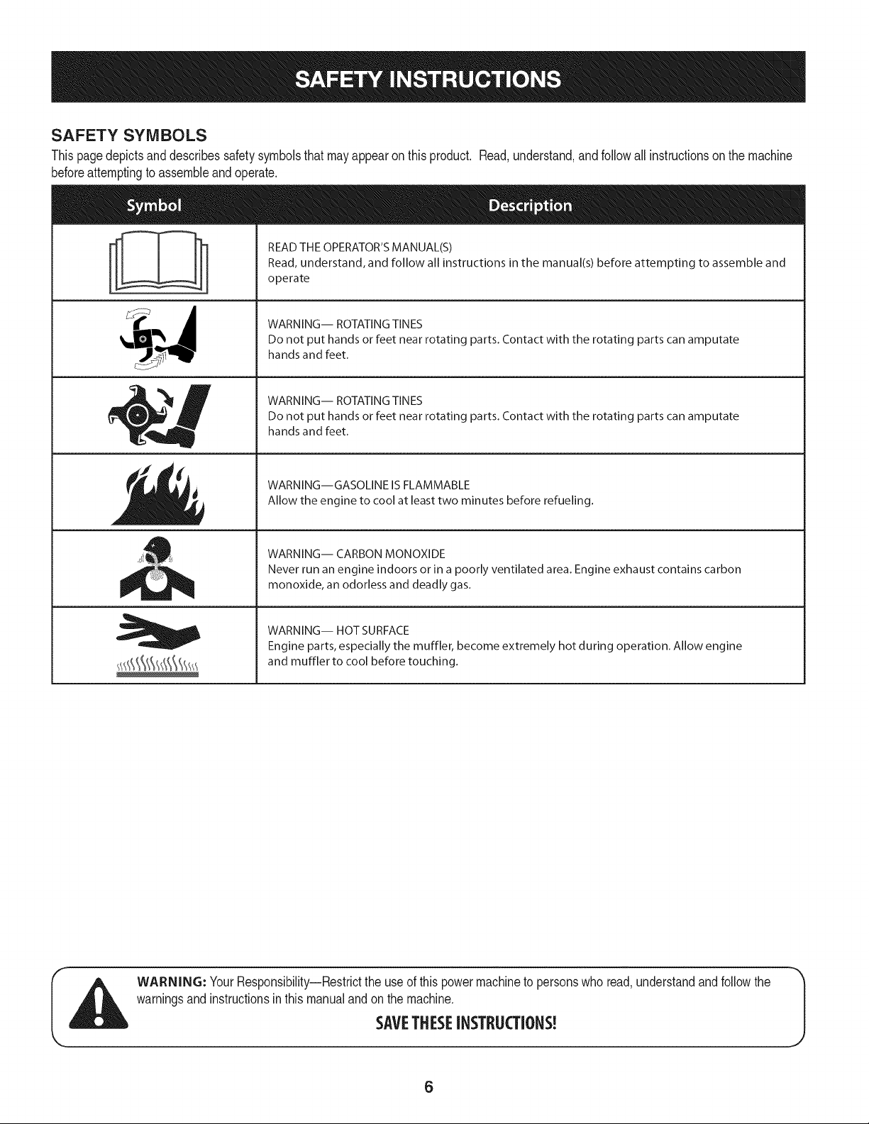
SAFETY SYMBOLS
Thispagedepictsand describessafetysymbolsthatmayappearonthisproduct. Read,understand,andfollowall instructionson the machine
beforeattemptingto assembleand operate.
i
i
READ THE OPERATOR'S MANUAL(S)
Read, understand, and follow all instructions in the manual(s) before attempting to assemble and
operate
WARNING-- ROTATING TINES
Do not put hands or feet near rotating parts. Contact with the rotating parts can amputate
hands and feet.
WARNING-- ROTATING TINES
Do not put hands or feet near rotating parts. Contact with the rotating parts can amputate
hands and feet.
WARNING--GASOLINE IS FLAMMABLE
Allow the engine to cool at least two minutes before refueling.
WARNING-- CARBON MONOXIDE
Never run an engine indoors or in a poorly ventilated area. Engine exhaust contains carbon
monoxide, an odorless and deadly gas.
WARNING-- HOT SURFACE
Engine parts, especially the muffler, become extremely hot during operation. Allow engine
and muffler to cool before touching.
WARNING: YourResponsibility--Restrictthe useof this powermachineto personswho read,understandand followthe
warningsand instructionsin this manualand on the machine.
SAVETHESEINSTRUCTIONS!
6
IMPORTANT:Thisunit is shippedwithoutgasolineor oil inthe engine.
Becertainto serviceenginewithgasolineandoilas instructedinthe
Operationsectionof this manualbeforeoperatingyourmachine.
NOTE:Referenceto rightand left hand sideof the Tilleris observed
fromthe operatingposition.
OPENING CARTON
1. Removeall staplesfromaroundthe bottomof the perimeter.
2. Removethe cartonfromthe skid.
3. Removeall looseparts.
4. Removeloosepackingmaterial.
REMOVING UNiT FROM SKiD
1. Thetiller is heavy,do notattemptto removeit fromthe skiduntil
instructedto do so intheseassemblysteps.
2. Checkcarton thoroughlyfor anyotherlooseparts.
LOOSE PARTS IN CARTON
• HandlebarAssembly
• Tiller
• EngineOil
• Operator'sManual
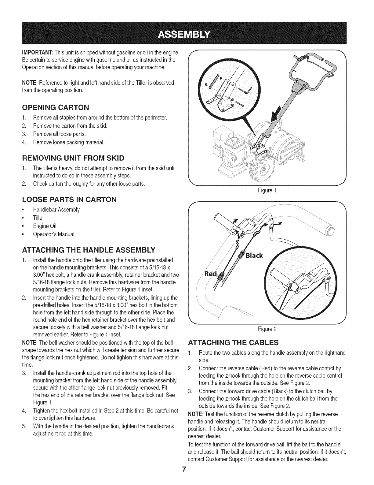
ATTACHING THE HANDLE ASSEMBLY
1. Installthe handleontothetiller usingthe hardwarepreinstalled
onthe handlemountingbrackets.Thisconsistsof a 5/16-18x
3.00"hex bolt,a handlecrankassembly,retainerbracketandtwo
5/16-18flangelocknuts. Removethis hardwarefromthe handle
mountingbracketson the tiller.Referto Figure1inset.
2. Insertthe handleintothe handlemountingbrackets,lining upthe
pre-drilledholes.Insertthe5/16-18x 3.00" hexbolt in the bottom
holefromthe left handside throughto the otherside.Placethe
roundholeendof the hex retainerbracketoverthe hexbolt and
securelooselywitha bellwasherand5/16-18flangelocknut
removedearlier.Referto Figure1 inset.
NOTE:Thebellwashershouldbe positionedwith the top of the bell
shapetowardsthe hexnutwhichwill createtensionandfurthersecure
theflange lock nutonce tightened.Donot tightenthishardwareatthis
time.
3. Installthe handle-crankadjustmentrodintothe top hole of the
mountingbracketfrom the lefthandsideof the handleassembly,
securewiththe otherflangelocknut previouslyremoved.Fit
the hexend of the retainerbracketoverthe flangelocknut.See
Figure1.
4. Tightenthe hexbolt installedin Step2 at this time. Be carefulnot
to overtightenthis hardware.
5. Withthe handleinthe desiredposition,tightenthe handlecrank
adjustmentrodat thistime.
Figure1
/
J
Figure2
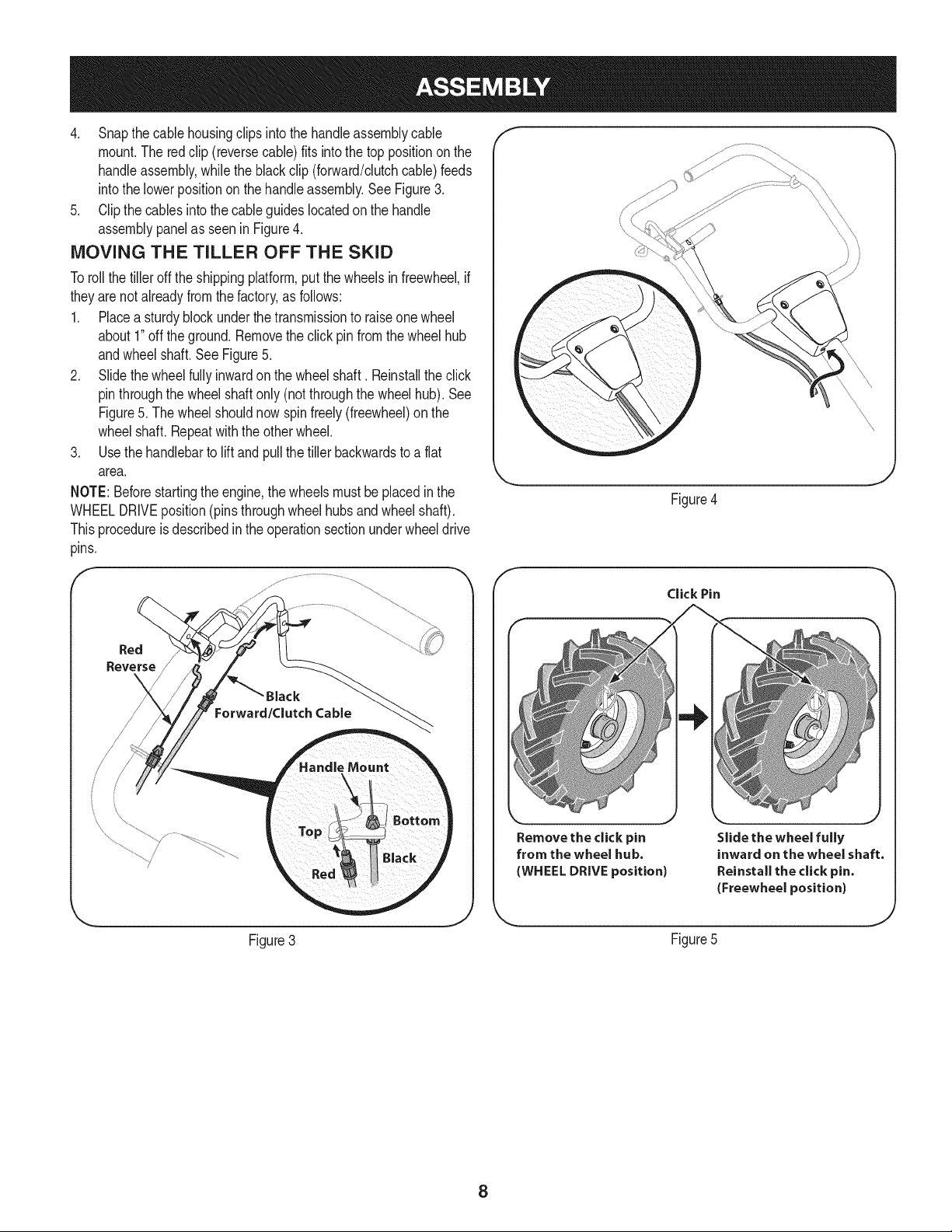
ATTACHING THE CABLES
1. Routethe two cables alongthe handleassemblyon the righthand
side.
2. Connectthe reversecable(Red)to the reversecablecontrolby
feedingthez-hookthroughthe holeon the reversecablecontrol
fromthe insidetowardstheoutside.SeeFigure2.
3. Connecttheforwarddrivecable(Black) to the clutchbailby
feedingthez-hookthroughthe holeon the clutchbailfromthe
outsidetowardsthe inside. See Figure2.
NOTE:Testthefunctionof the reverseclutchby pullingthe reverse
handleand releasingit. The handleshouldreturnto its neutral
position.If it doesn't,contactCustomerSupportforassistanceor the
nearestdealer.
Totest the functionof the forwarddrivebail, liftthe bailto the handle
and releaseit.The bailshouldreturnto itsneutralposition.If it doesn't,
contactCustomerSupportfor assistanceor the nearestdealer.
7
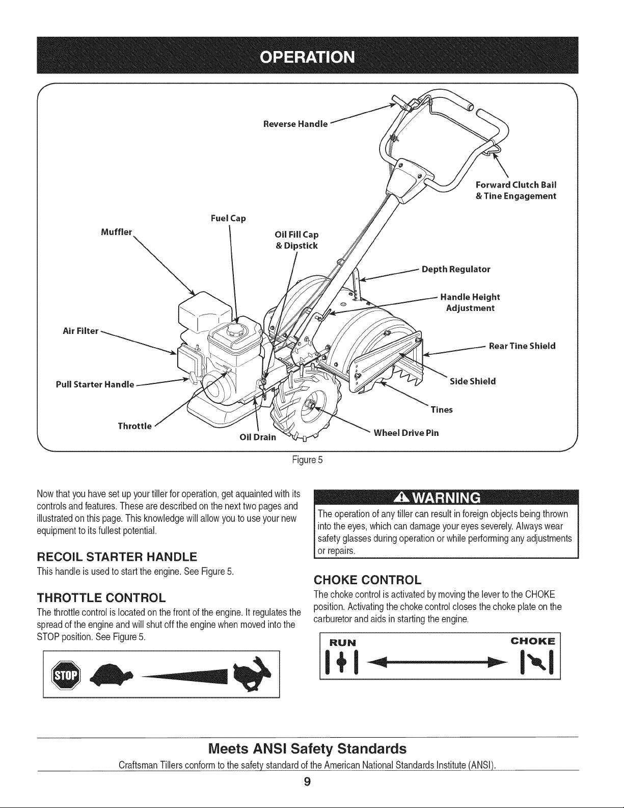
4. Snapthe cablehousingclips intothe handleassemblycable
mount.The red clip (reversecable)fits into thetop positiononthe
handleassembly,whilethe blackclip (forward/clutchcable)feeds
intothe lowerpositiononthe handleassembly.See Figure3.
5. Clipthe cablesintothe cableguideslocatedon the handle
assemblypanelas seenin Figure4.
MOVING THE TILLER OFF THE SKID
Toroll the tiller off the shippingplatform,putthe wheelsinfreewheel,if
theyarenotalreadyfromthe factory,as follows:
1. Placea sturdyblock underthe transmissionto raiseone wheel
about1"off theground.Removetheclick pinfromthe wheelhub
andwheelshaft. See Figure5.
2. Slidethewheelfullyinwardon the wheelshaft. Reinstallthe click
pinthroughthe wheelshaftonly (notthroughthe wheelhub).See
Figure5. The wheelshouldnowspinfreely(freewheel)on the
wheelshaft. Repeatwith the otherwheel.
3. Use the handlebarto liftand pullthetiller backwardsto a flat
area.
NOTE:Beforestartingthe engine,the wheelsmustbe placedinthe
WHEELDRIVEposition(pins throughwheelhubsandwheelshaft).
Thisprocedureis describedin the operationsectionunderwheeldrive
pins.
f
Figure4
f
Click Pin
Remove the click pin
from the wheel hub.
(WHEEL DRIVE position)
Slide the wheel fully
inward on the wheel shaft.
Reinstall the click pin.
(Freewheel position)
Figure3 Figure5
J
8
f
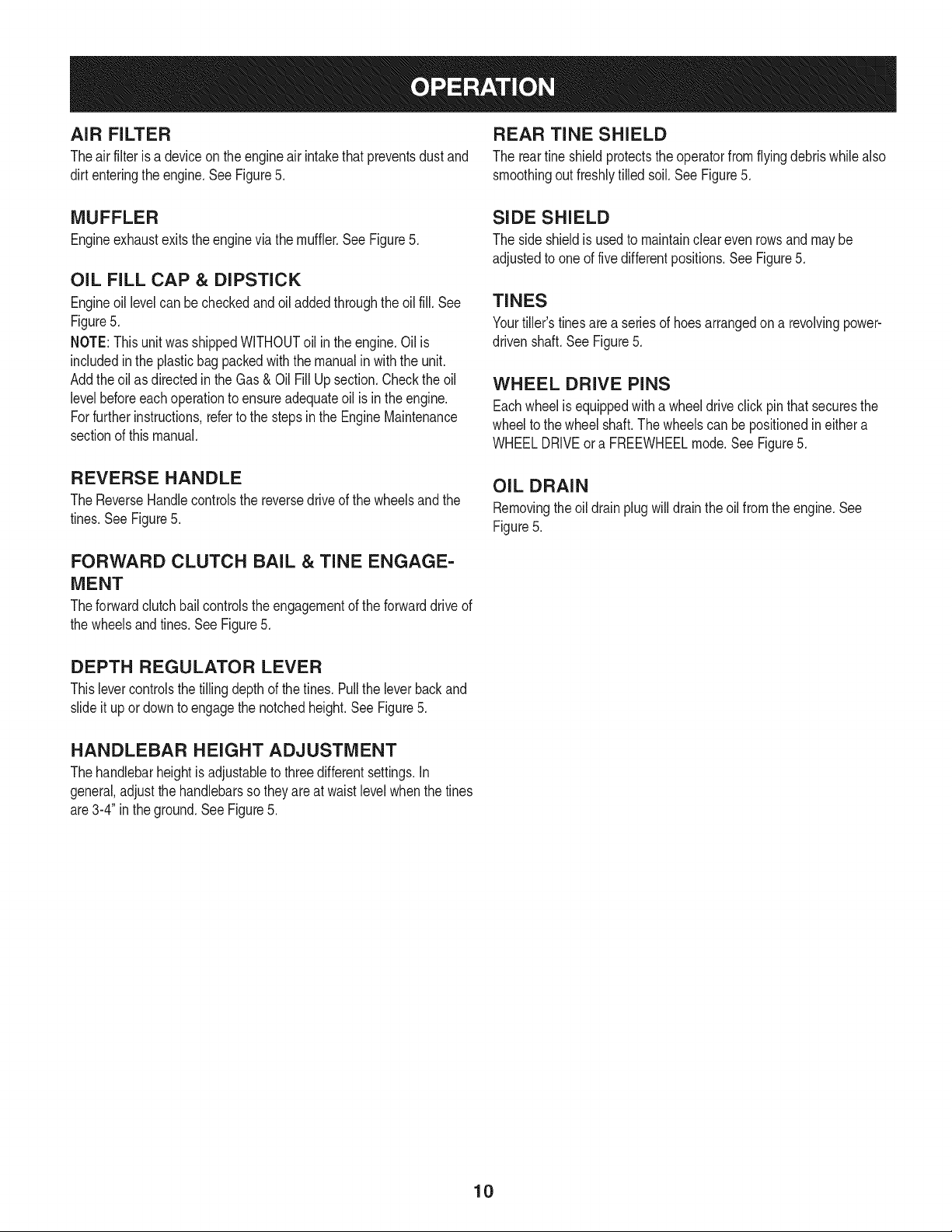
Reverse Handle
Fuel Cap
OU Fill Cap
& Dipstick
Depth Regulator
Forward Clutch Bail
& Tine Engagement
Air
Handle Height
Adjustment
Rear Tine Shield
Pull Starter Handle Side Shield
Throttle
Oil Drain
Tines
Wheel Drive Pin
Figure5
Nowthat youhavesetup yourtillerfor operation,get aquaintedwith its
controlsandfeatures.Thesearedescribedonthe nexttwopagesand
illustratedon thispage.This knowledgewill allowyou to useyour new
equipmentto itsfullestpotential.
RECOIL STARTER HANDLE
Thishandleis usedto startthe engine.See Figure5.
THROTTLE CONTROL
Thethrottlecontrolis locatedon thefrontof theengine.It regulatesthe
spreadof the engineandwill shutoff theenginewhen movedintothe
STOPposition.See Figure5.
The operationof anytiller can resultinforeignobjectsbeingthrown
intothe eyes,which can damageyoureyesseverely.Alwayswear
safetyglassesduringoperationor whileperforminganyadjustments
or repairs.
CHOKE CONTROL
The chokecontrolis activatedby movingthe leverto the CHOKE
position.Activatingthe chokecontrol closesthe chokeplateonthe
carburetorandaids instartingthe engine.
RUN CHOKE
Meets ANSi Safety Standards
CraftsmanTillersconformto the safety standardof the AmericanNationalStandardsInstitute(ANSI).
9
AiR FILTER REAR TJNE SHIELD
Theair filter isa deviceonthe engineair intakethatpreventsdust and The rear fine shieldprotectsthe operatorfromflying debriswhilealso
dirt enteringthe engine.See Figure5. smoothingoutfreshlytilled soil.See Figure5.
MUFFLER
Engineexhaustexitsthe enginevia the muffler.SeeFigure5.
OIL FILL CAP & DIPSTICK
Engineoil levelcan becheckedand oiladdedthroughtheoil fill. See
Figure5.
NOTE:This unitwasshippedWITHOUToil inthe engine.Oil is
includedinthe plasticbag packedwiththe manualinwiththe unit.
Addtheoil as directedin theGas & OilFill Up section.Checkthe oil
levelbeforeeachoperationto ensureadequateoil is inthe engine.
Forfurther instructions,referto the stepsinthe EngineMaintenance
sectionof this manual.
REVERSE HANDLE
The ReverseHandlecontrolsthe reversedriveof the wheelsandthe
tines.See Figure5.
FORWARD CLUTCH BAiL & TINE ENGAGE-
MENT
Theforwardclutchbailcontrolstheengagementof theforwarddriveof
the wheelsandtines.See Figure5.
SIDE SHIELD
The side shieldis usedto maintaincleareven rowsand may be
adjustedto oneof fivedifferentpositions.See Figure5.
TINES
Yourfiller's tinesarea seriesof hoesarrangedon a revolvingpower-
drivenshaft. See Figure5.
WHEEL DRIVE PiNS
Eachwheelis equippedwith a wheeldriveclickpinthat securesthe
wheelto the wheelshaft.The wheelscan bepositionedineithera
WHEELDRIVEora FREEWHEELmode.SeeFigure5.
OiL DRAIN
Removingtheoil drainplugwilldrain the oil from the engine.See
Figure5.
DEPTH REGULATOR LEVER
Thislevercontrolsthe tillingdepthof the tines.Pullthe leverbackand
slideit up or downto engagethe notchedheight.See Figure5.
HANDLEBAR HEIGHT ADJUSTMENT
Thehandlebarheightis adjustableto threedifferentsettings.In
general,adjustthe handlebarsso theyareat waistlevelwhenthe tines
are3-4" in the ground.See Figure5.
10
GAS AND OiL FILL-UP f "_
Oil (one bottle shipped with unit)
FirstTime Use
1. Removeoilfill dipstick.
2. With the tilleron levelground,usea funnelto emptyentire
contentsofoil bottle providedintothe engine.
3. Replaceoil fill dipstickand tighten.
Subsequent Uses
Only usehigh qualitydetergentoil ratedwithAPIserviceclassification
SF,SG, SH,SJor higher.Selectthe oil's SAEviscositygradeaccord-
ingto the expectedoperatingtemperature.Followthe chart below.
oc
Althoughmulti-viscosityoils (5W30,10W30,etc.)improvestarting
in coldweather,theywill result in increasedoil consumptionwhen
usedabove32°RCheckyourengineoil levelmorefrequentlyto avoid
possibleenginedamagefrom runninglowon oil.
1. Checkthe oil levelmakingcertainnotto rubthe dipstickalong
the insidewallsof the oil fill tube.This would resultin a false
dipstickreading.Wipedipstickcleanwith cloth. Replacedipstick
into theoil fillerneck, butdo not screwit in. Removeand check
oil level.Refillto FULLmarkon dipstick,if necessary.Capacityis
approximately20oz.Overfillingwill causethe engineto smoke
profuselyand will resultin poorengineperformance.
2. Replaceoil fill dipstickand tighten.
3. Keepoil levelat FULL.Runningthe enginewith too little oil can
resultinpermanentenginedamage.
Transmission/Gear Oil
FirstTime Use
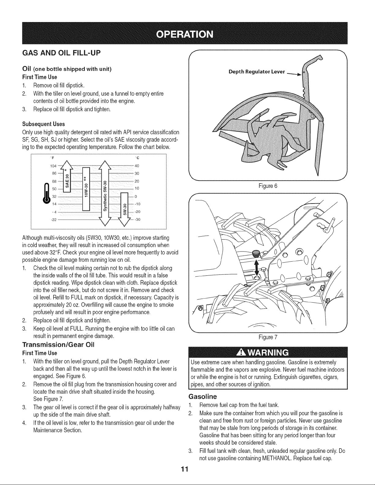
1. Withthe tilleron levelground,pullthe DepthRegulatorLever
backandthenall thewayup untilthe lowestnotchin the leveris
engaged.See Figure6.
2. Removethe oil fill plug from the transmissionhousingcoverand
locatethe maindrive shaftsituatedinsidethe housing.
See Figure7.
3. The gearoil levelis correctif the gear oil is approximatelyhalfway
up theside of the maindriveshaft.
4. If the oil levelis low, referto the transmissiongearoilunderthe
MaintenanceSection.
Depth Regulater Lever
11
Figure6
\
Figure7
J
Useextremecarewhen handlinggasoline.Gasolineis extremely
flammableandthevaporsare explosive.Neverfuel machineindoors
or whiletheengineis hot or running.Extinguishcigarettes,cigars,
pipes,andothersourcesof ignition.
Gasoline
1. Removefuel capfrom the fueltank.
2. Makesurethe containerfrom whichyou will pourthe gasolineis
cleanand free from rust or foreignparticles.Neverusegasoline
that maybe stalefromlongperiodsof storageinits container.
Gasolinethat has been sittingforany periodlongerthan four
weeksshouldbeconsideredstale.
3. Fillfuel tank with clean,fresh,unleadedregulargasolineonly. Do
not usegasolinecontainingMETHANOL.Replacefuel cap.
Alcoholblendedfuels(calledgasoholorusingethanolormethanol)
canattractmoisturewhichleadstoseparationandformationofacids
duringstorage.Acidicgascandamagethefuelsystemofanengine
whileinstorage.
Toavoidengineproblems,thefuelsystemshouldbeemptiedbefore
storagefor30daysorlonger.Drainthegastank,starttheengine
andletitrununtilthefuellinesandcarburetorareempty.Usefresh
fuelnextseason.SeeSTORAGEInstructionsforadditionalinforma-
tion.
Neveruseengineorcarburetorcleanerproductsinthefueltankor
permanentdamagemayoccur.
NOTE:Checkthefuellevelperiodicallytoavoidrunningoutof
gasolinewhileoperatingthetiller.
10.Pulltheropewitharapid,continuous,fullarmstroke.Keepafirm
griponthestarterhandle.Lettheroperewindslowly.
11.Repeat,ifnecessary,untilenginestarts.Whenenginestarts,
movechokecontrolgraduallytowardtheRUNI _'I position..
12.Ifenginefalters,movechokecontrolbacktowardtheCHOKE
I_,1positionandrepeatsteps5though8.
13.ALWAYSkeepthethrottlecontrolintheSTART/RUN(Rabbit
positionwhenoperatingthetiller.
TO STOP ENGINE
1. To stopthe wheelsandtines, releasethe ForwardClutchBail.
2. Movethrottlecontrol leverto slow(turtle) '_ position.
Wheneverpossible,graduallyreduceengine speedbefore
stoppingengine.
3. Movethrottlecontrol leverto STOP or OFFposition.
4. Turnthefuel shut-offvalveto the OFFposition.
5. Disconnectspark plugwireandgroundit againsttheengineto
preventaccidentalstartingwhilethe equipmentis unattended.
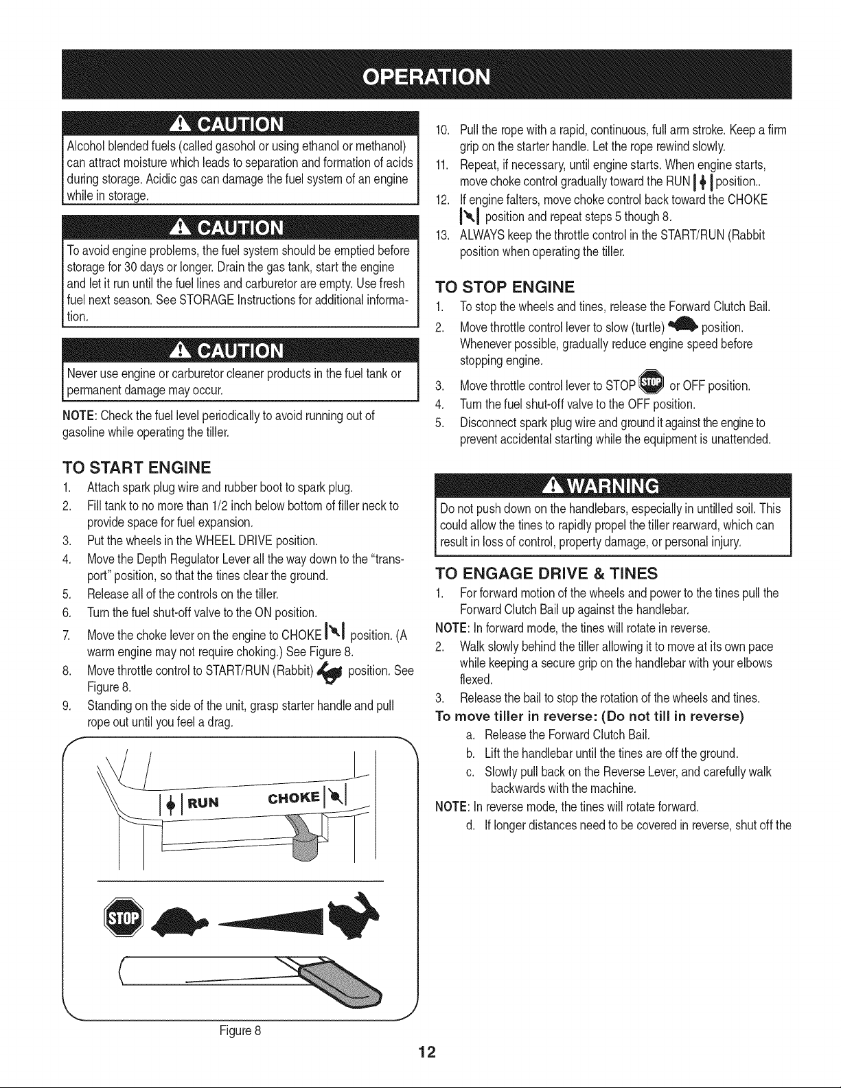
TO START ENGINE
1. Attachspark plugwire and rubberbootto sparkplug.
2. Filltank to no morethan 1/2 inch belowbottomof filler neckto
providespacefor fuelexpansion.
3. Putthewheelsinthe WHEELDRIVEposition.
4. Movethe DepthRegulatorLeverall the way downto the "trans-
port" position,so that the tinesclearthe ground.
5. Releaseallof the controlson the tiller.
6. Turnthefuel shut-offvalveto the ON position.
7. Movethe chokeleveron theengine to CHOKEI'_1 position.(A
warmenginemaynot requirechoking.)See Figure8.
8. Movethrottlecontrolto START/RUN(Rabbit)_ position.See
Figure8.
9. Standingon the sideof the unit,graspstarterhandleandpull
ropeout untilyoufeel a drag.
f
__jL
Do not pushdown onthe handlebars,especiallyin untilledsoil. This
couldallowthe tinesto rapidlypropelthetiller rearward,which can
resut n ossof contro, propertydamage,or persona njury.
TO ENGAGE DRIVE & TINES
1. Forforwardmotionof the wheelsandpowerto the tines pull the
ForwardClutchBail up againstthe handlebar.
NOTE:Inforwardmode,the tineswill rotatein reverse.
2. Walk slowlybehindthetiller allowingit to moveat its own pace
while keepinga securegrip on the handlebarwith yourelbows
flexed.
3. Releasethe bailto stopthe rotationof the wheelsandtines.
To move tiller in reverse: (Do not till in reverse)
a. Releasethe ForwardClutchBail.
b. Liftthe handlebaruntilthe tinesareoffthe ground.
c. Slowlypullbackon the ReverseLever,and carefullywalk
backwardswiththe machine.
NOTE:In reversemode,the tines will rotateforward.
d. Iflongerdistancesneedto becoveredin reverse,shutoff the
J
Figure8
12
engine,thenplacethe two wheelsin FREEWHEEL.
TURNING THE TILLER
1. Practiceturningthetiller in a level,open area. Be very carefulto
keepyourfeetandlegsawayfrom the tines.
2. Tobegina turn,lift the handlebarsuntilthe tinesareout of the
groundandthe engineandtinesare balancedoverthewheels.
3. Withthe tiller balanced,pushsidewayson the handlebarto steer
inthe directionof the turn.Afterturning,slowlylowerthetines into
Becertainsparkplugwireis disconnectedand groundedagainstthe
enginewhen performinganyadjustments.
the soilto resumetilling.
SETTING THE DEPTH
Tillingdepthis controlledby the depthstakewhichcan beadjustedto
fivedifferentsettings.Adjustthe side shieldsas youadjustthedepth
stake.
• Whenusingthe tillerfor thefirst time,use the secondadjustment
holefromthe top (1"of tillingdepth).
• Whenbreakingup sod and for shallowcultivation,usethe setting
whichgives1"of tillingdepth (secondholefromthe top).Place
the sideshields in theirlowestposition.
• Forfurther depth,raisethe depthstakeandside shieldsandalso
makeoneor twomorepassesoverthe area.
• Whentillingloosesoil, thedepth stakemaybe raisedto its
highestposition(usebottomadjustmenthole)to give the deepest
tillingdepth. Raisethe sideshieldsto their highestposition.
• Totransporttiller, lowerthe depthstake(usetop adjustment
hole).
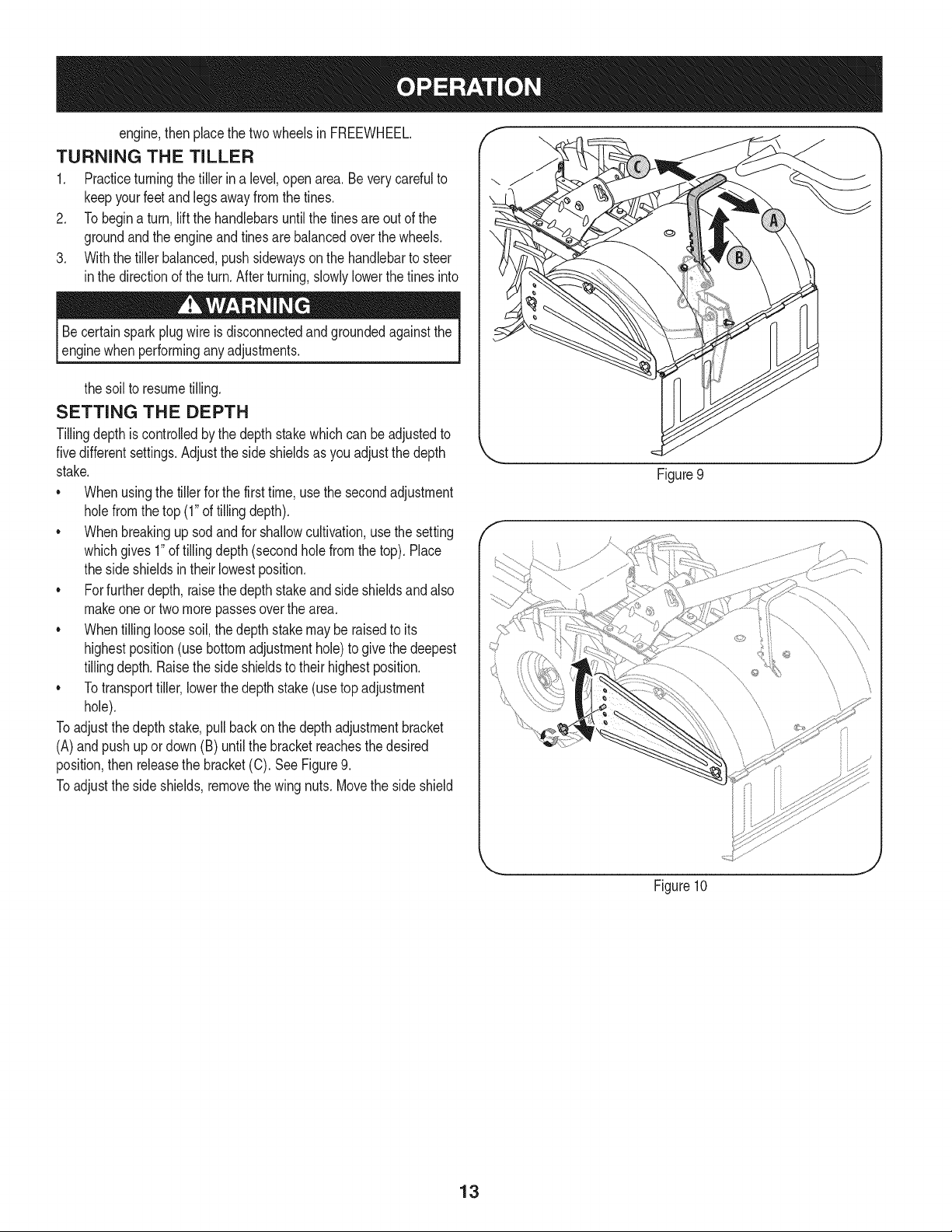
Toadjustthe depthstake,pullbackonthe depthadjustmentbracket
(A)andpush upordown (B)until the bracketreachesthe desired
position,then releasethe bracket(C). See Figure9.
Toadjustthe side shields,removethe wing nuts.Movethe side shield
Figure9
Figure10
J
13
to the desiredpositionandreplacethewing nuts.Tightensecurely.
SeeFigure10.
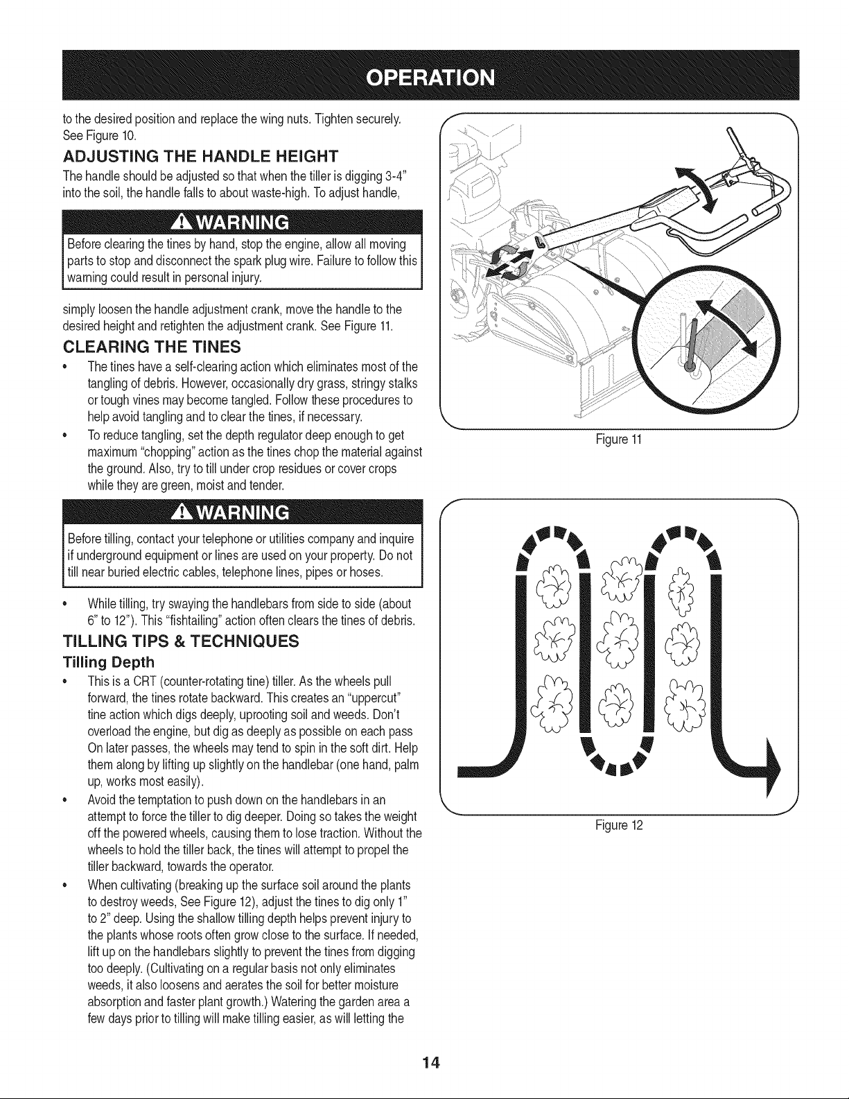
ADJUSTING THE HANDLE HEIGHT
Thehandle shouldbe adjustedso thatwhenthe tilleris digging3-4"
intothe soil, the handlefalls to aboutwaste-high.Toadjusthandle,
Beforeclearingthe tines by hand,stopthe engine,allowall moving
partsto stopanddisconnectthe sparkplugwire.Failureto follow this
warningcould resultin personalinjury.
simplyloosenthe handleadjustmentcrank,movethe handleto the
desiredheightandretightenthe adjustmentcrank.See Figure11.
CLEARING THE TINES
* Thetines havea self-clearingactionwhich eliminatesmostof the
tanglingof debris. However,occasionallydry grass,stringystalks
ortoughvines may becometangled.Followtheseproceduresto
helpavoidtanglingandto clearthe tines,if necessary.
* Toreducetangling,setthe depth regulatordeep enoughto get
maximum"chopping"actionas the tineschopthe materialagainst
the ground.Also,try to till undercrop residuesor covercrops
whilethey are green,moistand tender.
Beforetilling,contactyourtelephoneor utilitiescompanyandinquire
if undergroundequipmentor linesare usedon yourproperty.Do not
till near buriedelectriccables,telephonelines,pipesor hoses.
* Whiletilling,try swayingthe handlebarsfromsideto side (about
6"to 12").This"fishtailing"actionoftenclearsthe tinesof debris.
TILLING TIPS & TECHNIQUES
Tilling Depth
* Thisis a CRT(counter-rotatingtine)tiller.As the wheelspull
forward,the tinesrotatebackward.Thiscreatesan "uppercut"
tineaction whichdigs deeply,uprootingsoilandweeds.Don't
overloadthe engine,butdig as deeplyas possibleon eachpass
Onlater passes,the wheelsmaytendto spin in the soft dirt. Help
themalongby liftingupslightlyon the handlebar(one hand,palm
up,worksmosteasily).
* Avoidthe temptationto pushdownon the handlebarsin an
attemptto forcethe tiller to digdeeper.Doingso takestheweight
offthe poweredwheels,causingthem to losetraction.Withoutthe
wheelsto holdthe tillerback,the tineswillattemptto propelthe
tillerbackward,towardsthe operator.
* Whencultivating(breakingup the surfacesoil aroundthe plants
to destroyweeds,SeeFigure12),adjust the tinesto dig only 1"
to 2" deep.Usingthe shallowtillingdepth helpspreventinjuryto
the plantswhoserootsoftengrowcloseto the surface.If needed,
lift uponthe handlebarsslightlyto preventthe tinesfromdigging
too deeply.(Cultivatingona regularbasisnotonly eliminates
weeds,it alsoloosensand aeratesthesoil for bettermoisture
absorptionandfasterplantgrowth.)Wateringthe gardenarea a
fewdayspriorto tillingwill maketilling easier,as will lettingthe
Figure11
f
Figure12
14
newlyworkedsoil set fora day or two beforemakinga final, deep
tillingpass.
Choosing the Correct Wheel & Tine Speeds
Withexperience,youwill findthe tillingdepthand tilling speed
combinationthat is best for yourgarden.Setthe enginethrottleleverat
a speedto givethe engineadequatepowerand yet allowit to operate
at the slowestpossiblespeeduntilyou haveachievedthe maximum
tillingdepthyoudesire. Fasterenginespeedsmaybedesirable
whenmakingfinalpassesthroughthe seedbedorwhencultivating.
Selectionof the correctenginespeed,in relationto the tillingdepth,
willensurea sufficientpowerlevelto dothe jobwithoutcausingthe
engineto labor.
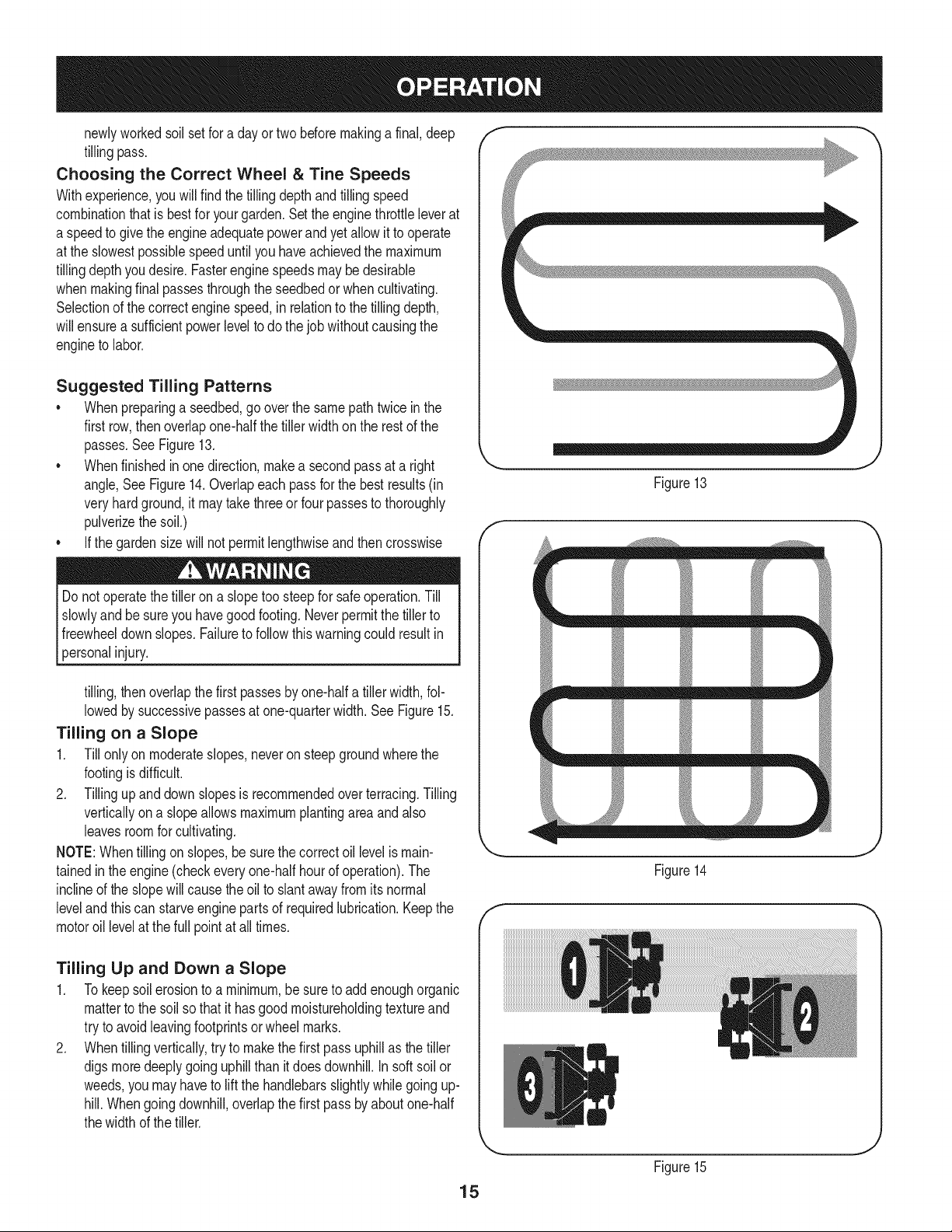
Suggested Tilling Patterns
• Whenpreparinga seedbed,go overthe samepathtwice inthe
first row,thenoverlapone-halfthetiller width on the rest of the
passes.SeeFigure13.
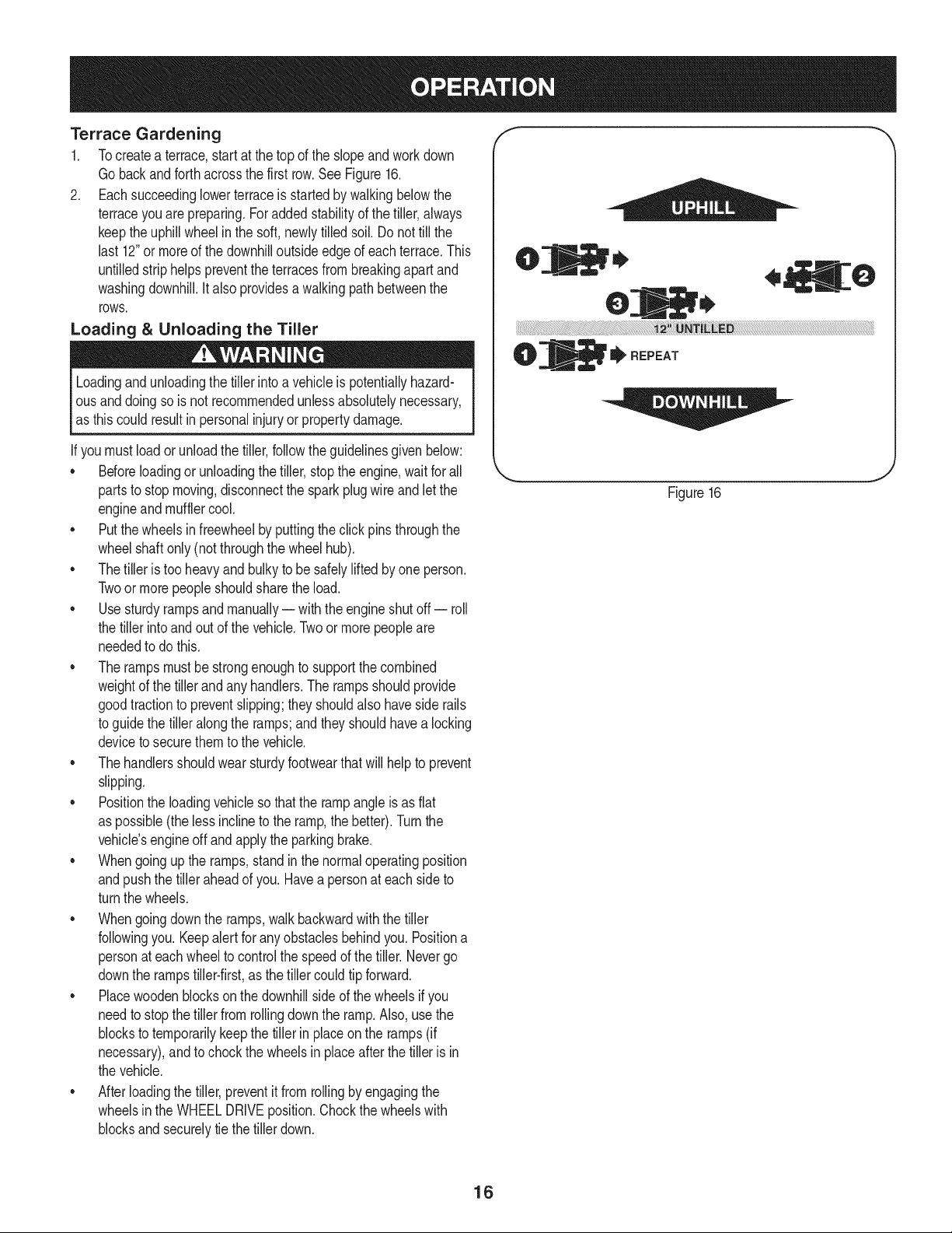
• Whenfinishedin one direction,makea secondpassat a right
angle,See Figure14.Overlapeach passfor the best results(in
veryhardground,itmaytakethreeor four passesto thoroughly
pulverizethe soil.)
• Ifthe gardensizewill not permitlengthwiseand then crosswise
Do notoperatethe tilleron a slopetoo steepfor safe operation.Till
slowlyandbe sureyou havegood footing.Neverpermitthetiller to
freewheeldownslopes.Failureto followthis warningcouldresultin
[persona njury.
tilling,then overlapthefirst passesbyone-halfa tillerwidth,fol-
lowedby successivepassesat one-quarterwidth.See Figure15.
Tilling on a Slope
1. Till onlyon moderateslopes,neveron steep groundwherethe
footingisdifficult.
2. Tillingup and downslopesisrecommendedoverterracing.Tilling
verticallyona slopeallowsmaximumplantingarea and also
leavesroomfor cultivating.
NOTE:Whentilling on slopes,besurethe correctoil levelismain-
tainedin the engine(checkeveryone-halfhour of operation).The
inclineof the slopewillcause theoil to slantawayfromitsnormal
leveland this can starveengine partsof requiredlubrication.Keepthe
motoroil levelat thefull pointat alltimes.
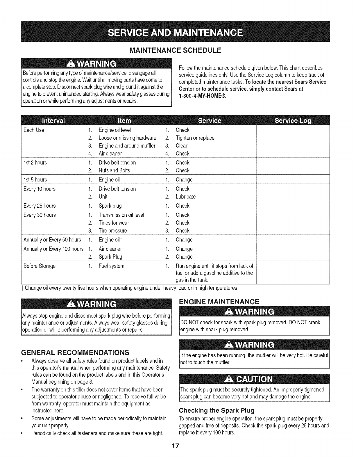
Tilling Up and Down a Slope
1. Tokeepsoil erosionto a minimum,be sureto addenoughorganic
matterto thesol so that it hasgood moistureholdingtextureand
try to avoidleavingfootprintsor wheel marks.
2. Whentillingvertically,try to makethe first passuphillas the tiller
digs moredeeplygoing uphillthan it doesdownhill.In soft soilor
weeds,you mayhaveto lift the handlebarsslightlywhilegoingup-
hill.Whengoingdownhill,overlapthe first pass byaboutone-half
thewidth of the tiller.
f
Figure13
J
f
T
mm _
f
Figure14
J
15
Figure15
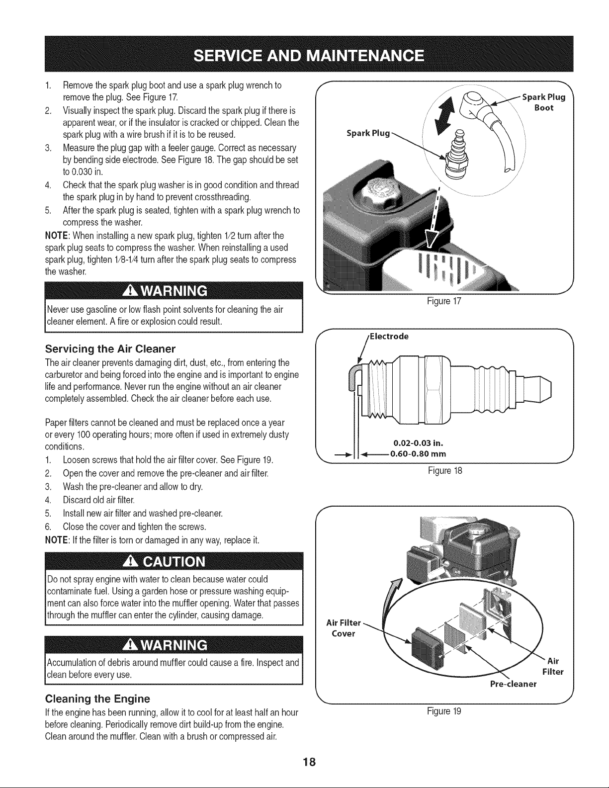
Terrace Gardening
1. Tocreatea terrace,start at thetop of the slopeand work down
Gobackandforthacrossthe first row.See Figure16.
2. Eachsucceedinglowerterraceis startedby walkingbelowthe
terraceyouare preparing.Foraddedstabilityof thetiller,always
keepthe uphillwheelin the soft,newlytilled soil.Donot till the
last 12"or moreof thedownhilloutside edgeof each terrace.This
untilledstrip helps preventtheterracesfrombreakingapart and
washingdownhill.Italso providesa walkingpathbetweenthe
rows.
Loading &Unloading the Tiller
Loadingandunloadingthe tiller intoa vehicleispotentiallyhazard-
ous anddoingso is not recommendedunlessabsolutelynecessary,
as this couldresultinpersonalinjuryor propertydamage.
If youmustloador unloadthe tiller,followthe guidelinesgiven below:
• Beforeloadingor unloadingthe tiller,stop the engine,wait forall
partsto stopmoving,disconnectthe sparkplug wireandlet the
engineandmufflercool.
• Putthe wheelsin freewheelby puttingthe clickpins throughthe
wheelshaftonly (notthroughthe wheelhub).
• Thetiller is too heavyand bulky to be safelylifted by one person.
Twoor morepeopleshouldsharethe load.
• Usesturdyrampsand manually-- with theengineshutoff -- roll
the tillerintoand outof the vehicle.Twoor morepeopleare
neededto dothis.
• The rampsmustbe strongenoughto supportthe combined
weightof the tillerand any handlers.The rampsshouldprovide
goodtractionto preventslipping;they shouldalso havesiderails
to guidethe tiller alongthe ramps;and they shouldhavea locking
deviceto securethemto the vehicle.
• Thehandlersshouldwearsturdyfootwearthat will helpto prevent
slipping.
• Positionthe loadingvehicleso thatthe rampangle is as flat
as possible(theless inclineto the ramp,the better).Turnthe
vehicle'sengineoff and applythe parkingbrake.
• Whengoingup the ramps,stand in the normaloperatingposition
andpushthe tilleraheadof you. Haveapersonat eachside to
turnthe wheels.
• Whengoingdownthe ramps,walkbackwardwiththe tiller
followingyou.Keepalert for anyobstaclesbehindyou. Positiona
personat each wheelto controlthe speedof thetiller.Nevergo
downthe rampstiller-first,as the tiller couldtip forward.
• Placewoodenblocksonthe downhillside of thewheelsif you
needto stopthe tiller fromrollingdownthe ramp.Also,use the
blocksto temporarilykeepthe tillerin placeon the ramps(if
necessary),and to chockthe wheelsin placeafter the tilleris in
the vehicle.
• Afterloadingthe tiller,preventit from rollingbyengagingthe
wheelsinthe WHEELDRIVEposition.Chockthe wheelswith
blocksand securelytie thetiller down.
,O
O
_ REPEAT
Figure16
16
MAINTENANCE SCHEDULE
Beforeperforminganytypeof maintenance/service,disengageall
controlsand stoptheengine.Waituntilall movingpartshavecometo
acompletestop.Disconnectsparkplugwireandgrounditagainstthe
enginetopreventunintendedstarting.Alwayswearsafetyglassesduring
operationor whileperforminganyadjustmentsor repairs.
Followthe maintenanceschedulegivenbelow.Thischartdescribes
serviceguidelinesonly. Usethe ServiceLogcolumnto keeptrackof
completedmaintenancetasks.To locate the nearest Sears Service
Centeror to scheduleservice,simplycontactSears at
1-800-4-MY-HOME®.
EachUse
1st2 hours
1st5 hours
Every10hours
Every25 hours
Every30 hours
Annuallyor Every50 hours
Annuallyor Every 100hours
BeforeStorage
1. Engineoil level
2. Looseor missinghardware
3. Engineandaroundmuffler
4. Air cleaner
1. Drivebelt tension
2. Nutsand Bolts
1. Engineoil
1. Drivebelt tension
2. Unit
1. Sparkplug
1. Transmissionoil level
2. Tines for wear
3. Tire pressure
1. Engineoi11-
1. Air cleaner
2. SparkPlug
1. Fuelsystem
1. Check
2. Tightenorreplace
3. Clean
4. Check
1. Check
2. Check
1. Change
1. Check
2. Lubricae
1. Check
1. Check
2. Check
3. Check
1. Change
1. Change
2. Change
1. Runengine untilit stopsf_m lackd
fuel oradda gasolineadditiveto the
gas inthe tank.
Changeoil every twentyfive hourswhenoperatingengineunder heavyload or in high temperatures
Alwaysstopengineanddisconnectsparkplugwirebeforeperforming
lany maintenanceor adjustments.Alwayswearsafetyglassesduring
[operationorwhile performingany adjustmentsor repairs.
ENGINE MAINTENANCE
DO NOTcheckfor sparkwith spark plug removed.DO NOTcrank
enginewithsparkplug removed.
GENERAL RECOMMENDATIONS
•Alwaysobserveallsafetyrulesfoundonproductlabelsandin
thisoperator'smanualwhenperformingany maintenance.Safety
rulescan be foundonthe productlabelsandin thisOperator's
Manualbeginningon page3.
• Thewarrantyon this tillerdoes notcover itemsthathavebeen
subjectedto operatorabuseor negligence.Toreceivefull value
fromwarranty,operatormust maintainthe equipmentas
instructedhere.
• Someadjustmentswillhaveto be madeperiodicallyto maintain
yourunit properly.
• Periodicallycheckall fastenersand makesurethesearetight.
Ifthe enginehas beenrunning,the mufflerwill be very hot. Be careful
notto touch the muffler.
Thespark plug mustbesecurelytightened.An improperlytightened
sparkplugcan becomeveryhot andmaydamagethe engine.
Checking the Spark Plug
Toensureproperengineoperation,the sparkplugmustbeproperly
gappedandfree of deposits.Checkthe sparkplugevery25hoursand
replaceitevery100hours.
17
1. Removethespark plug bootanduse a sparkplugwrenchto
removethe plug.See Figure17.
2. Visuallyinspectthe spark plug.Discardthe spark plug if thereis
apparentwear,or if the insulatoris crackedor chipped.Cleanthe
sparkplugwitha wirebrush if it is to be reused.
3. Measurethe plug gap with a feelergauge.Correctas necessary
by bendingsideelectrode.SeeFigure18.The gap shouldbeset
to 0.030in.
4. Checkthatthe sparkplug washeris in goodconditionandthread
the sparkplugin by handto preventcrossthreading.
5. After thesparkplugis seated,tightenwith a spark plugwrenchto
compressthe washer.
NOTE:Wheninstallinga newspark plug,tighten1/2turn after the
sparkplugseatsto compressthe washer.Whenreinstallinga used
sparkplug,tighten 1/8-1/4turnafterthe sparkplugseatsto compress
the washer.
Neverusegasolineorlow flashpointsolventsfor cleaningthe air
c eanereement. A f re orexpos on cou d resut.
Servicing the Air Cleaner
Theair cleanerpreventsdamagingdirt, dust,etc.,fromenteringthe
carburetorand beingforcedintothe engineand is importantto engine
life andperformance.Neverrunthe enginewithoutan air cleaner
completelyassembled.Checkthe aircleanerbeforeeach use.
Paperfilterscannotbe cleanedandmustbe replacedonce a year
orevery 100operatinghours;moreoftenif usedin extremelydusty
conditions.
1. Loosenscrewsthatholdthe airfiltercover.SeeFigure19.
2. Openthe coverand removethe pre-cleanerandairfilter.
3. Washthe pre-cleanerandallowto dry.
4. Discardold air filter.
5. Installnewairfilterandwashedpre-cleaner.
6. Closethe coverand tightenthe screws.
NOTE:If the filter is torn or damagedin anyway,replaceit.
Donot sprayenginewith waterto clean becausewatercould
contaminatefuel. Usinga gardenhoseor pressurewashingequip-
mentcanalso forcewater intothe muffleropening.Waterthat passes
throughthe mufflercanenterthe cylinder,causingdamage.
Accumulationof debrisaroundmufflercouldcausea fire.Inspectand
cleanbeforeevery use.
Cleaning the Engine
If theengine hasbeenrunning,allowit to coolfor at leasthalfan hour
beforecleaning.Periodicallyremovedirt build-upfrom theengine.
Cleanaroundthe muffler.Cleanwith a brushor compressedair.
Boot
Figure17
0.02-0.03 in.
===_1 _=====0.60=0.80 mm
Figure18
J
E
Air Filter
Cover
Figure19
Pre<leaner
J
18
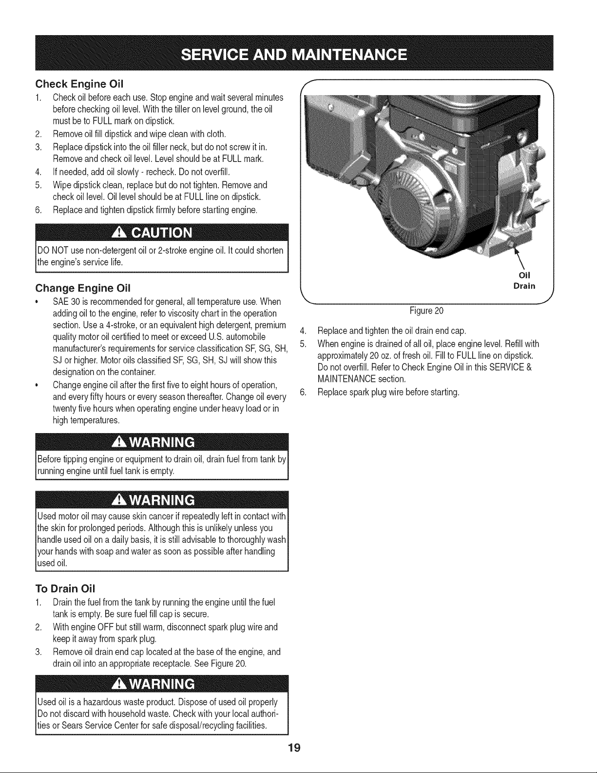
Check Engine Oil
1. Checkoil beforeeachuse. Stopengineandwaitseveralminutes
beforecheckingoil level.Withthe tilleron levelground,the oil
mustbe to FULLmarkon dipstick.
2. Removeoil fill dipstickandwipe cleanwith cloth.
3. Replacedipstick intothe oilfiller neck,but do not screwitin.
Removeand checkoil level.Levelshouldbeat FULLmark.
4. If needed,add oil slowly- recheck.Do not overfill.
5. Wipedipstickclean,replacebut do not tighten.Removeand
checkoil level.Oil levelshouldbe at FULLlineondipstick.
6. Replaceandtightendipstickfirmlybeforestartingengine.
DO NOTuse non-detergentoilor 2-strokeengineoil. Itcould shorten
the engine'sservicelife.
Change Engine Oil
•SAE30 is recommendedfor general,all temperatureuse.When
addingoilto theengine,referto viscositychartinthe operation
section.Usea4-stroke,oran equivalenthighdetergent,premium
qualitymotoroil certifiedto meetor exceedU.S.automobile
manufacturer'srequirementsfor serviceclassificationSF,SG, SH,
SJ or higher.MotoroilsclassifiedSF,SG, SH, SJwill showthis
designationon the container.
• Changeengineoil after thefirst fiveto eight hoursof operation,
andeveryfifty hoursor every seasonthereafter.Changeoil every
twentyfivehourswhenoperatingengineunder heavyload or in
hightemperatures.
Figure20
4. Replaceandtightenthe oildrainendcap.
5. Whenengineisdrainedof all oil, placeenginelevel.Refillwith
approximately20oz.of freshoil. Fillto FULLlineondipstick.
Donot overfill.Referto CheckEngineOil inthis SERVICE&
MAINTENANCEsection.
6. Replacesparkplugwire beforestarting.
Beforetippingengineor equipmentto drainoil, drain fuel fromtank by
runningengineuntilfuel tank isempty.
Usedmotoroil maycauseskincancerifrepeatedlyleft in contactwith
the skinfor prolongedperiods.Althoughthis isunlikelyunlessyou
handleusedoil on a daily basis,itis still advisableto thoroughlywash
yourhandswithsoapand wateras soonas possibleafter handling
usedoil.
To Drain Oil
1. Drainthe fuelfrom the tank by runningthe engineuntil thefuel
tankisempty.Be surefuel fill cap issecure.
2. Withengine OFF butstillwarm,disconnectspark plugwire and
keepitawayfromsparkplug.
3. Removeoil drainendcap locatedat the baseof the engine,and
drainoil into anappropriatereceptacle.See Figure20.
Usedoilisa hazardouswasteproduct.Disposeof usedoil properly
IDonot discardwithhouseholdwaste.Checkwithyourlocalauthori-
_tiesor SearsServiceCenterfor safedisposal/recyclingfacilities.
19
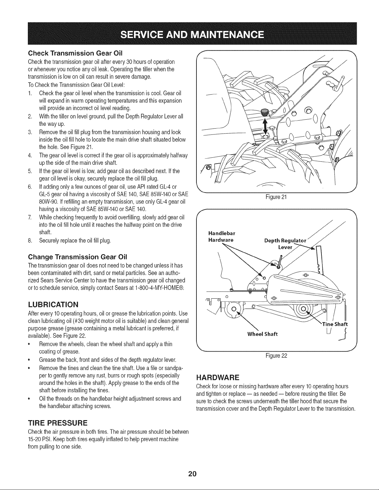
Check Transmission Gear Oil
Checkthetransmissiongear oil after every 30 hoursof operation
orwheneveryou noticeanyoil leak. Operatingthe tiller whenthe
transmissionis lowon oilcan resultin severedamage.
ToCheckthe TransmissionGearOil Level:
1. Checkthegearoil levelwhenthetransmissionis cool. Gearoil
will expandin warm operatingtemperaturesand this expansion
will providean incorrectoil levelreading.
2. With thetiller on levelground,pull the DepthRegulatorLeverall
the wayup.
3. Removetheoil fill plugfromthetransmissionhousingand look
insidethe oil fill hole to locate themaindrive shaftsituatedbelow
the hole.See Figure21.
4. Thegearoil levelis correctif the gearoilis approximatelyhalfway
upthe side of the maindriveshaft.
5. If thegearoil levelis low,add gearoil as describednext.Ifthe
gearoillevelis okay,securelyreplacethe oil fill plug.
6. If addingonlya fewouncesof gearoil, useAPI ratedGb4 or
Gb5 gearoil havinga viscosityof SAE 140,SAE85W-140or SAE
80W-90.Ifrefillingan emptytransmission,useonly Gb4 gear oil
havinga viscositydSAE 85W-140or SAE140.
7. Whilecheckingfrequentlyto avoidoverfilling,slowlyadd gear oil
intothe oil fill holeuntilit reachesthe halfwaypointon the drive
shaft.
8. Securelyreplacetheoil fill plug.
Change Transmission Gear Oil
Thetransmissiongearoildoes not needto be changedunlessit has
beencontaminatedwithdirt, sandor metalparticles.Seeanautho-
rizedSearsServiceCenterto havethetransmissiongearoil changed
orto scheduleservice,simplycontactSearsat 1-800-4-MY-HOME®.
LUBRICATION
Afterevery10operatinghours,oil or greasethe lubricationpoints.Use
cleanlubricatingoil (#30 weightmotoroil is suitable)andcleangeneral
purposegrease(greasecontaininga metallubricantis preferred,if
available).SeeFigure22.
• Removethewheels,clean thewheelshaft andapplya thin
coatingof grease.
• Greasethe back,frontandsidesof the depth regulatorlever.
• Removethetines and cleanthe fine shaft.Usea file or sandpa-
perto gentlyremoveany rust,burrsor roughspots(especially
aroundthe holesin the shaft). Applygreaseto the endsof the
shaftbeforeinstallingthe tines.
• Oilthe threadsonthe handlebarheightadjustmentscrewsand
the handlebarattachingscrews.
\
Figure21
Handlebar
Hardware Depth Reg_
Wheel Shaft
Figure22
Tine Shaft
J
HARDWARE
Checkfor looseor missinghardwareafterevery10operatinghours
andtightenor replace-- as needed-- beforereusingthe tiller. Be
sureto checkthe screwsunderneaththe tiller hoodthat securethe
transmissioncoverand the DepthRegulatorLeverto the transmission.
TIRE PRESSURE
Checktheair pressurein bothtires.The airpressureshouldbe betwen
15-20PSI.Keepbothtires equallyinflatedto helppreventmachine
frompullingto oneside.
2O
Beforeperformingany type of maintenanceonthe machine,waitfor
all partsto stopmovingand disconnectthe spark plugwire. Failure
to followthis instructioncouldresult in personalinjuryor property
damage.
BELT REPLACEMENT
Ifthe drive beltor augerbelts needto bereplaced,it is bestto replace
bothbelts at the sametime. Useonly a factory authorizedbeltas an
"over-the-counter"beltmaynot performsatisfactorily.The procedure
requiresaveragemechanicalabilityandcommonlyavailabletools.
To replacethe DriveandAugerbelts,followthesesteps:
1. Makesurethe tiller is ona flat surface,withthe engineturned
offandthe sparkplugwireunpluggedandgroundedto prevent
unintendedfiringof the engine.
2. Removethe beltcoverby first removingthe two1/4-20self-
tappinghexscrews.See Figure23. Liftthe beltcoverupand
awayfromthetiller and set in a safe locationuntilreinstallation.
3. Removethe four 1/4-20self-tappinghexscrewsthat securethe
pulleyshieldtothe frame and removethe pulleyshieldandset
asidein a safelocationuntil reinstallation.See Figure24.
4. Removethe idler bracketextensionspring.See Figure25. It is
recommendedto use a pairof needle-nosedpliers,and grabthe
springby theendthat hooksoverthe frame.Simplygrab it and
pullit awayfromthe frame,thenupwardsandcarefullyrelieve
thetensionof the spring.
5. Removethe idler pulleybracketby removingthe 5/16-24hex
headscrew,flatwasherandlockwasher.See Figure26.
NOTE:It willbe necessaryto removethe beltfromaroundthe idler
pulleybyworkingit off the pulleyandfromunderneatheach belt
keeper.
Figure24
Figure25
f
Figure23
J
f
Remove the
idler pulley
bracket by
removing the
he× head screw,
flat and lock
washers
Figure26
21
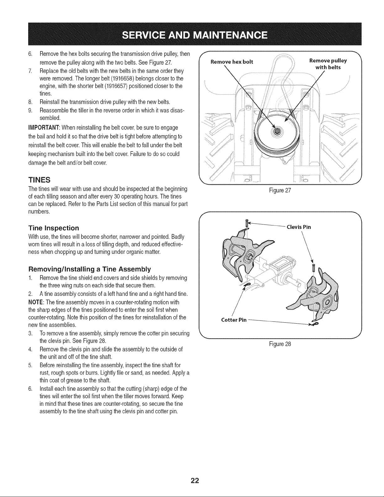
6. Removethehex boltssecuringthe transmissiondrivepulley,then
removethe pulleyalongwith the two belts. See Figure27.
7. Replacetheold beltswiththe new beltsin the sameorderthey
wereremoved.The longerbelt (1916658)belongscloserto the
engine,with the shorterbelt (1916657)positionedcloser to the
tines.
8. Reinstallthe transmissiondrive pulleywith the new belts.
9. Reassemblethe tiller in the reverseorder in whichit was disas-
sembled.
IMPORTANT:Whenreinstallingthe beltcover,be sureto engage
the bailandholdit so thatthe drivebelt is tight beforeattemptingto
reinstallthe beltcover.This will enablethe beltto fall underthebelt
keepingmechanismbuiltintothe beltcover.Failureto do so could
damagethe beltand/or belt cover.
f
x
TINES
Thetines will wearwithuseand shouldbe inspectedat the beginning
of eachtilling seasonand after every30 operatinghours.Thetines
can bereplaced.Refertothe PartsListsectionof thismanualfor part
numbers.
Tine inspection
Withuse,the tineswill becomeshorter,narrowerandpointed.Badly
worntines will resultin a lossof tilling depth,and reducedeffective-
nesswhenchoppingup andturningunderorganicmatter.
Removing/Installing a Tine Assembly
1. Removethefine shieldendcoversand sideshieldsby removing
the threewingnutsoneach sidethat securethem.
2. A fineassemblyconsistsof a left hand fineanda righthandtine.
NOTE:Thefine assemblymovesina counter-rotatingmotionwith
the sharpedgesof the tines positionedto enterthe soil firstwhen
counter-rotating.Notethis positionof thetinesfor reinstallationof the
newtine assemblies.
3. Toremovea tine assembly,simplyremovethe cotterpin securing
the clevispin.SeeFigure28.
4. Removetheclevispin and slidethe assemblyto the outsideof
the unitand off of the tine shaft.
5. Beforereinstallingthe fineassembly,inspectthe fine shaftfor
rust, roughspotsor burrs.Lightlyfile or sand,as needed.Applya
thincoat of greaseto the shaft.
6. Installeachfineassemblyso thatthecutting (sharp)edgeof the
tineswillenterthe soil firstwhenthe tiller movesforward.Keep
in mindthat thesetines are counter-rotating,so securethe fine
assemblyto the fine shaftusingthe clevispin and cotterpin.
Figure27
Figure28
J
22
Neverstoretiller withfuel in tankindoorsor in poorlyventilatedareasI
wherefuel fumesmayreachan open flame,spark,or pilotlightas on
a furnace,waterheater,c othesdryer,orgas app ance. 1
Neverleaveengineunattendedwhileit is running.
PREPARING THE ENGINE
Enginesstored between30 and 90 daysneedto betreatedwith a
gasolinestabilizerandenginesstoredover90daysneedto bedrained
of fuel to preventdeteriorationandgumfrom formingin fuel systemor
on essentialcarburetorparts.If the gasolineinyourenginedeterio-
ratesduringstorage,you mayneed to havethecarburetor,andother
fuel systemcomponents,servicedor replaced.
1. Removeallfuel fromtankby runningengineuntilit stopsfrom
lackof fuel.
2. Changethe oil. See ChangeEngineOil inSERVICEAND
MAINTENANCEsection.
3. Removespark plugand pourabouta 1/2ounceof engineoil into
the cylinder.Replacesparkplugandcrankit slowlyto distribute
oil.
4. Cleandebrisfrom aroundtheengineandthe muffler.Touchup
any damagedpaint,and coat otherareasthat may rustwith a light
filmof oil.
5. Storein a clean,dry andwellventilatedarea awayfromany ap-
pliancethat operateswith a flame or pilot light,suchas a furnace,
waterheater,orclothesdryer.Alsoavoidany areawith a spark
producingelectricmotor,orwherepowertoolsare operated.
6. Ifpossible,also avoidstorageareaswith high humidity,because
that promotesrust and corrosion.
7. Keeptheengine levelinstorage.Tiltingcan causefuel or oil
leakage.
PREPARING THE TILLER
Whenthe tillerwon't be usedfor an extendedperiod,prepareit for
storageas follows:
1. Cleanthe tillerandengine.
2. Followthe lubricationrecommendationsandcheckfor looseparts
and hardware.
3. Storethe tiller ina clean,dry area.
4. Neverstorethe tillerwith fuel in the fuel tank in an enclosedarea
wheregas fumescould reachan open flameor spark,or where
ignitionsourcesare present(spaceheaters,hot waterheaters,
furnaces,etc.).
23
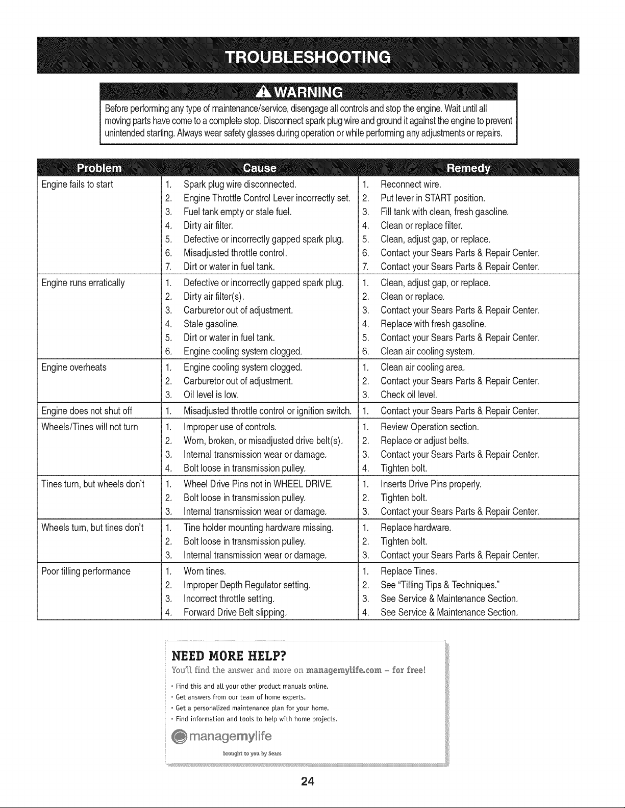
Beforeperforminganytype dmaintenance/service,disengageallcontrolsand stoptheengine.Waituntilall
movingpartshavecometo a completestop.Disconnectsparkplugwireandgroundit againsttheenginetoprevent
unintendedstarting.Alwayswearsafetyglassesduringoperationor whileperforminganyadjustmentsorrepairs.
Enginefailsto start
Enginerunserratically
Engineoverheats
Enginedoesnot shut off
Wheels/Tineswill notturn
Tinesturn, butwheelsdon't
Wheelsturn,buttines don't
Poortilling performance
1. Sparkplugwire disconnected.
2. EngineThrottleControlLeverincorrectlyset.
3. Fueltankemptyor stale fuel.
4. Dirtyair filter.
5. Defectiveor incorrectlygappedsparkplug.
6. Misadjustedthrottlecontrol.
7. Dirt or water in fuel tank.
1. Defectiveor incorrectlygappedsparkplug.
2. Dirtyair filter(s).
3. Carburetorout of adjustment.
4. Stalegasoline.
5. Dirt or water in fuel tank.
6. Enginecoolingsystemclogged.
1. Enginecoolingsystemclogged.
2. Carburetorout of adjustment.
3. Oil levelis low.
1. Misadjustedthrottlecontrolor ignitionswitch.
1. Improperuse of controls.
2. Worn,broken,or misadjusteddrive belt(s).
3. Internaltransmissionwearor damage.
4. Bolt loosein transmissionpulley.
1. WheelDrivePinsnot in WHEELDRIVE.
2. Bolt looseintransmissionpulley.
3. Internaltransmissionwearor damage.
1. Tine holdermountinghardwaremissing.
2. Bolt looseintransmissionpulley.
3. Internaltransmissionwearor damage.
1. Worntines.
2. ImproperDepthRegulatorsetting.
3. incorrectthrottlesetting.
4. ForwardDriveBeltslipping.
1. Reconnectwire.
2. Putleverin STARTposition.
3. Filltank with clean,fresh gasoline.
4. Cleanor replacefilter.
5. Clean, adjustgap,or replace.
6. Contactyour SearsParts& RepairCenter.
7. Contactyour SearsParts& RepairCenter.
1. Clean,adjustgap,or replace.
2. Cleanor replace.
3. Contactyour SearsParts& RepairCenter.
4. Replacewithfreshgasoline.
5. Contactyour SearsParts& RepairCenter.
6. Cleanair coolingsystem.
1. Cleanair coolingarea.
2. Contactyour SearsParts& RepairCenter.
3. Checkoil level.
1. Contactyour SearsParts& RepairCenter.
1. ReviewOperationsection.
2. Replaceor adjustbelts.
3. Contactyour SearsParts& RepairCenter.
4. Tightenbolt.
1. InsertsDrivePinsproperly.
2. Tightenbolt.
3. Contactyour SearsParts& RepairCenter.
1. Replacehardware.
2. Tightenbolt.
3. Contactyour SearsParts& RepairCenter.
1. ReplaceTines.
2. See"TillingTips& Techniques."
3. SeeService& MaintenanceSection.
4. SeeService& MaintenanceSection.
NEED MORE HELP?
Youq] [h}d the m_swe_ and mo_}_ on ma_agemy[_eo_em - fear f_'ee!
Find this and air your other product manuats ontine.
Get answers from our team of home experts.
Get a personatized maintenance ptan for your home.
Find information and toots to hetp with home projects.
÷ managemylife
_O_ght te yeI:_ by Sea_s
24

25
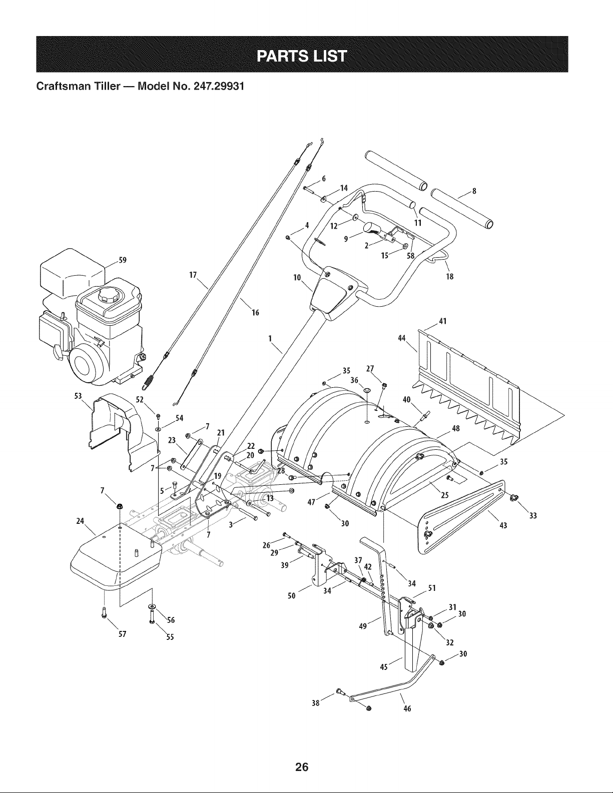
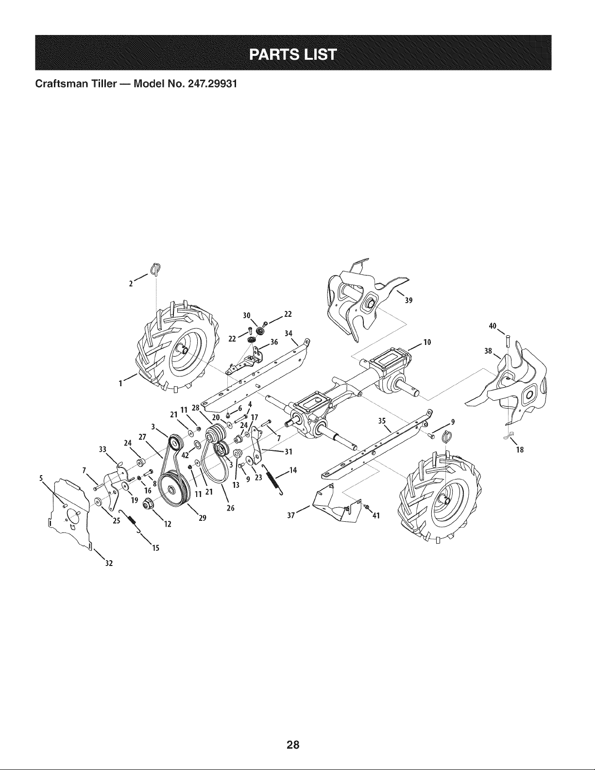
Craftsman Tiller BIViodel No. 247.29931
._ 17 10
\
\
18
53
1 44
\ \
4O
48
35
24 \30 \43
5O
49 _
57
3O
26
Craftsman Tiller BIViodel No. 247.29931
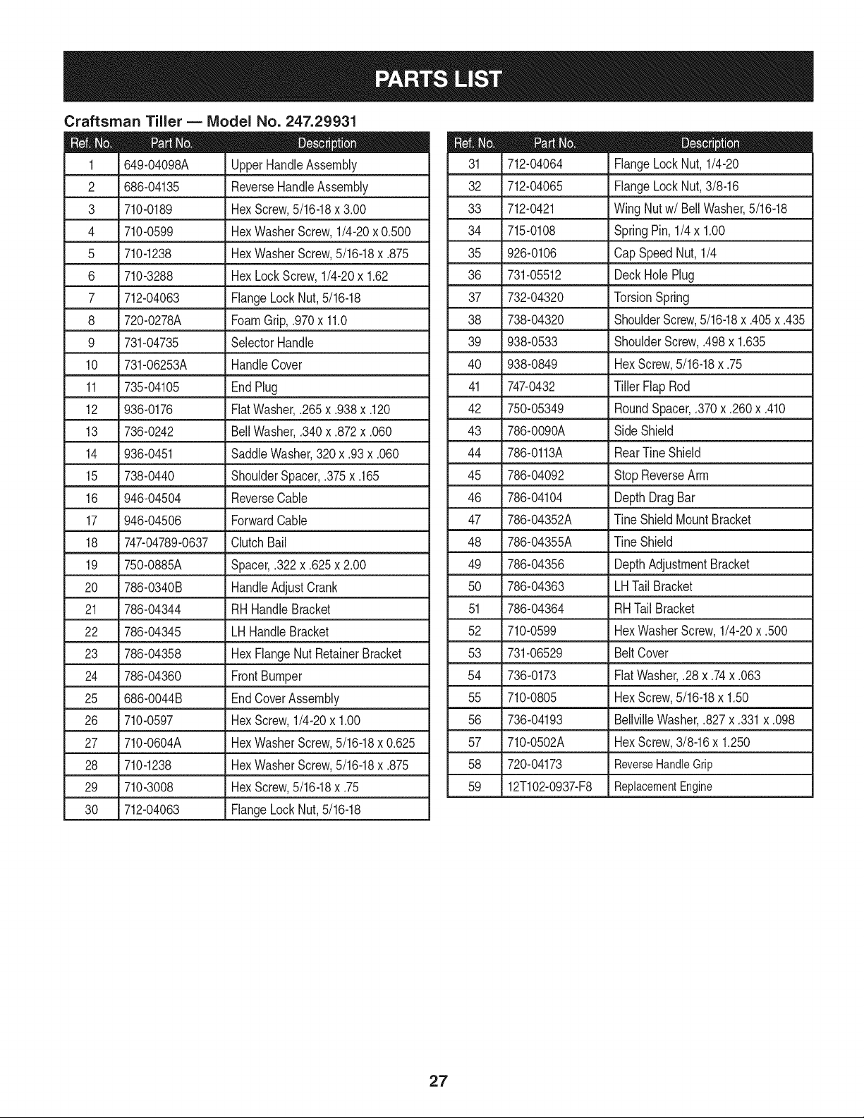
2
3
4
5
6
7
649-04098A
686-04135
710-0189
710-0599
710-1238
710-3288
712-04063
UpperHandleAssembly
ReverseHandleAssembly
HexScrew,5/16-18x 3.00
HexWasherScrew,1/4-20x 0.500
HexWasherScrew,5/16-18x .875
HexLockScrew,1/4-20x 1.62
FlangeLock Nut,5/16-18
8 720-0278A FoamGrip,.970x 11.0
9 731-04735 SelectorHandle
10 731-06253A HandleCover
11 735-04105
12 936-0176
13 736-0242
14 936-0451
15 738-0440
EndPlug
FiatWasher,.265x.938x.120
BellWasher,.340x.872x.060
SaddleWasher,320 x .93 x.060
ShoulderSpacer,.375x.165
16 946-04504 ReverseCable
17 946-04506 ForwardCable
18 747-04789-0637 ClutchBail
19 750-0885A
20 786-0340B
21 786-04344
22 786-04345
23 786-04358
24 786-04360
25 686-0044B
26 710-0597
27 710-0604A
28 710-1238
29 710-3008
30 712-04063
Spacer,.322x.625x 2.00
HandleAdjustCrank
RHHandleBracket
LHHandleBracket
HexFlangeNut RetainerBracket
FrontBumper
EndCoverAssembly
HexScrew,1/4-20x 1.00
HexWasherScrew,5/16-18x 0.625
HexWasherScrew,5/16-18x .875
HexScrew,5/16-18x .75
FlangeLock Nut,5/16-18
712-04064 FlangeLockNut, 1/4-20
32 712-04065 FlangeLockNut,3/8-16
33 712-0421 WingNut w/Bell Washer,5/16-18
34 715-0108 SpringPin, 1/4x 1.00
35 926-0106 CapSpeedNut,1/4
36 731-05512 DeckHole Plug
37 732-04320 TorsionSpring
38 738-04320 ShoulderScrew,5/16-18x .405x.435
39 938-0533 ShoulderScrew,.498x 1.635
40 938-0849 HexScrew,5/16-18x .75
41 747-0432 TillerFlap Rod
42 750-05349 RoundSpacer,.370x.260x.410
43 786-0090A SideShield
44 786-0113A RearTineShield
45 786-04092 StopReverseArm
46 786-04104 DepthDragBar
47 786-04352A TineShield MountBracket
48 786-04355A TineShield
49 786-04356 DepthAdjustmentBracket
50 786-04363 LHTail Bracket
51 786-04364 RHTailBracket
52 710-0599 HexWasherScrew,1/4-20x .500
53 731-06529 BeltCover
54 736-0173 Fiat Washer,.28 x.74x.063
55 710-0805 HexScrew,5/16-18x 1.50
56 736-04193 BellvilleWasher,.827x.331x.098
57 710-0502A HexScrew,3/8-16x 1.250
58 720-04173 ReverseHandleGrip
59 12T102-O937-F8 ReplacementEngine
27
Craftsman Tiller B Model No. 247.29931
33
7
3O
\
34
32
I0
40\
38
19
26
25_ 312 29 37/
\15
28
Craftsman Tiller BIViodel No. 247.29931
934-04652 CompleteWhl. Ass., 13x 5 x 6 (B, C)
2 714-0143A Click Pin
3 684-04168 Idler PulleyAssembly
4 710-0331 HexHeadScrew,3/8-24x 2.25 25
5 710-0170 HexHeadScrew,5/16-24x .625 26
6 710-0599 SelfTappingScrew,1/4-20x .500 27
7 710-0606 HexHeadScrew,1/4-20x 1.50 28
8 710-0672 HexHeadScrew,5/16-18x 1.25 29
9 710-1880 HexHeadScrew,5/16-18x .75,Patch 30
10 918-04815A TransmissionAssembly 31
11 712-04064 NylonHexLockNut, 1/4-20 32
12 712-0700 Nut,9/16-18,FlangeLock 33
13 718-04407 Hub, 5/8 Spline 34
14 732-04085 ExtensionSpring,.480ODX 5.00 LG 35
15 732-04276A ExtensionSpring,LT5PTO 36
16 936-0119 LockWasher,5/16 37
17 736-0173 Washer,.28x.74x.063 38
18 714-04043 InternalCotterPin 39
19 736-0343 FlatWasher,.330X 1.25X .120 40
20 936-0452 BellWasher,.396x 1.140x .095
21 736-3092 FlatWasher,.265x 1.0x .030
738-04425 ShoulderScrew,.342x.335 1/4-28
23 748-04087A PivotIdlerSpacer
24 750-04571 ShoulderSpacer,.260x.785x.538
750-04907 PivotIdlerSpacer
754-04090 V-Belt,4L x 25.375Long
754-04091 V-Belt,3L x 29.125Long
756-04198A EnginePulley
756-04355 TransmissionPulley
756-0625 CableRoller
786-04312 IdlerBracket,Forward
786-04343-4044 CoverPlate
786-04346
786-04416A-4044
786-04415B-4044
786-04357-4044
786-04371-4044
642-04071-4044
642-04072-4044
911-0415
IdlerBracket,Reverse
MountingFrame,RH
MountingFrame,LH
PulleyBracket
PulleyShield
Tine Assembly,LH
Tine Assembly,RH
ClevisPin,.375x 1.75
41 710-0896 HexWasherScrew,1/4-14x .625
42 736-0315 FlatWasher,.760x 1.500x .120
29
Craftsman Tiller B Model No. 247.29931
12
2
iiT
18
6
\4
19
2o \
17 18
14
21
7
11
1o
6
14
7
21
\
\
3O
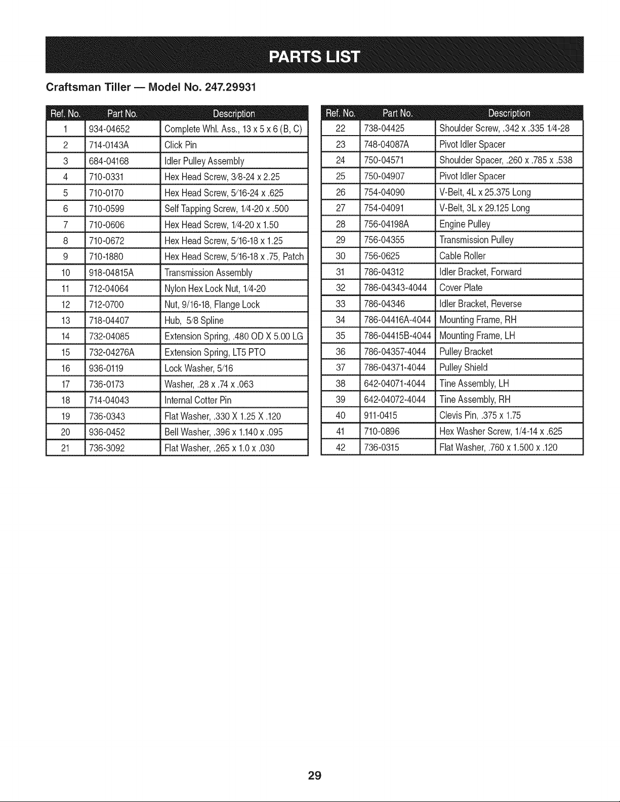
Craftsman Tiller BIViodel No. 247.29931
D = t 0
918-04815A TransmissionAssembly
1 919-04184A Housing,Transmission
2 710-3008 HexScrew,5/16-18,.75,Gr5
3 911-04844 Shaft,Tiller
4 911-04854 Shaft,Wheel
5 911-05028 Shaft,Worm
6 714-04059 Key, Hi Pro.25x 1.062
7 716-0204 Retaining Ring
8 716-04102 RetainingRing,Int
9 917-04380 WormGear,61t,RH
10 917-04381 WormGear,30t, LH
11 918-04435 BearingCover
12 921-04030 Seal,Oil, .750Shaftx 1.783Bore
13 921-04229 Gasket,GearHousing
14 721-04232 Seal,Oil, 1.00Shaftx 2.00 Bore
15 721-04271 RubberPlug,Oil
16 732-0614 Wire Ring
17 736-04305*
-- 736-04306"
-- 736-04307"
-- 736-04308"
18 736-0745
19 941-04298
20 941-04299
21 741-3114
Washer,Flat,1.50x 1.75x .062
Washer,Flat,1.50x 1.75x .005
Washer,Flat,1.50x 1.75x .03
Washer,Flat,1.50x 1.75x .010
Washer,Flat,1.010x 1.56x .060
Cone Bearing
BearingCup
Ball Bearing
22 786-04366 Cover,Transmission
23 786-04392 Cover,Transmission
* Theflatwasherslistedare usedas requiredto obtain.005to .015
inallowableend playonthe driveshaft.
31
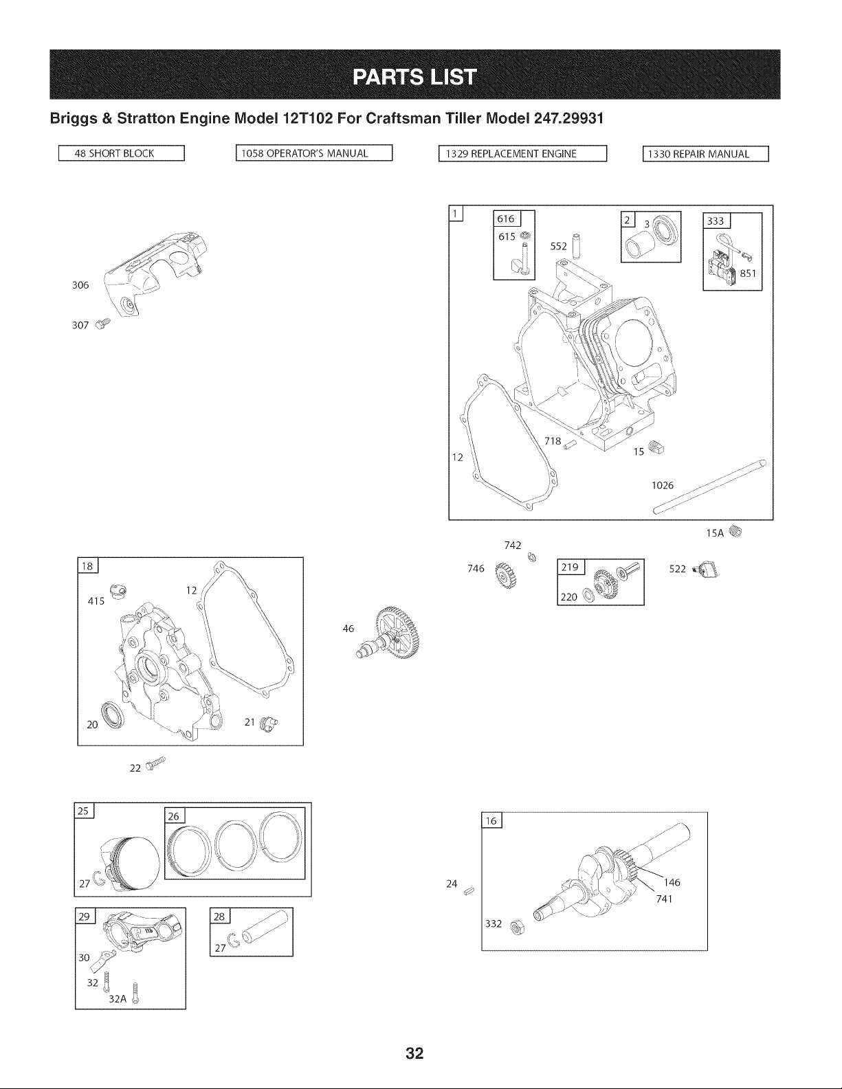
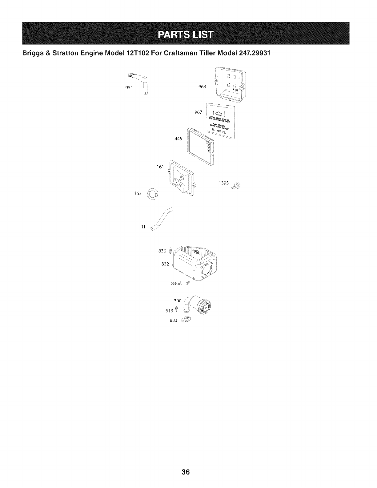
Briggs & Stratton Engine Model 12T102 For Craftsman Tiller Model 247.29931
306
307 _
1026
Y
415
12
46
742
746 _ 12191 ,_
122o_T_
22
24
0
332 _
146
741
32
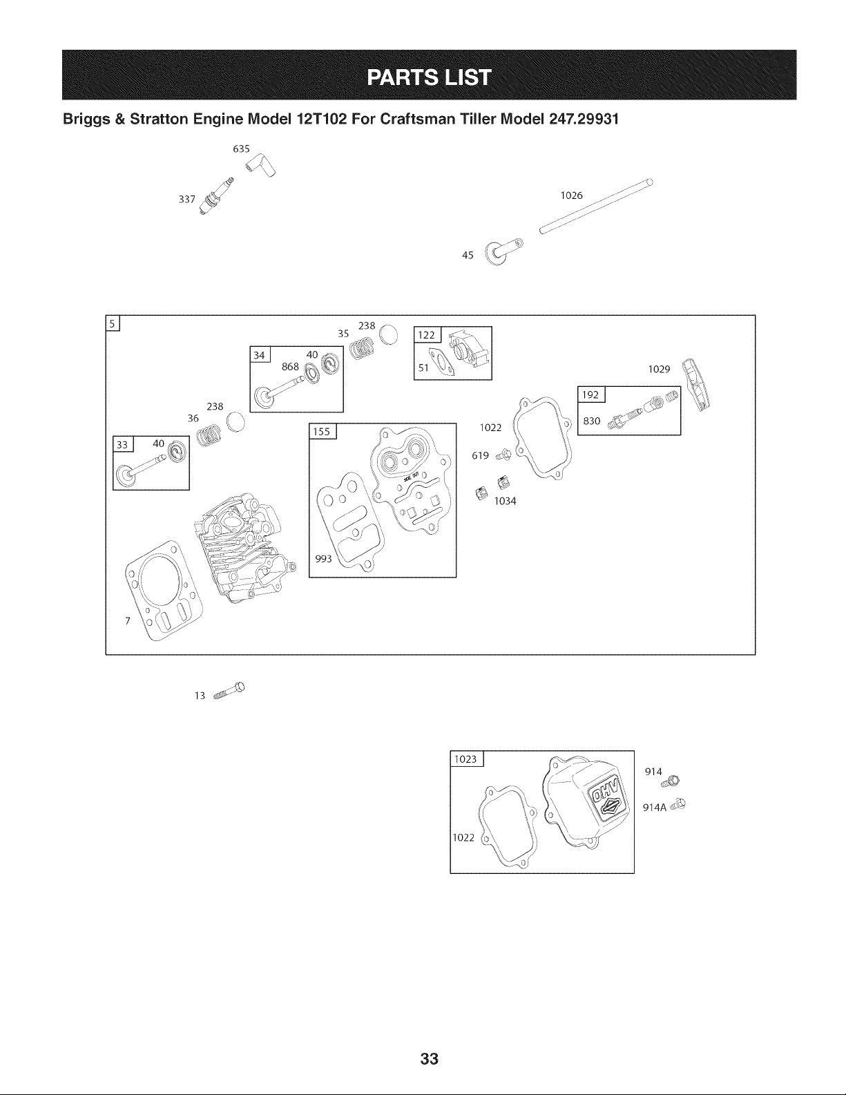
Briggs & Stratton Engine Model 12T102 For Craftsman Tiller Model 247.29931
635
45
1026 ........fJ;" .......
...... 7;;;:;:7;7;77;......
C;<.......
Y
238
4o_
..._ t% ,i
_jj --
1022
619
1034
1029
1022
914A_
33
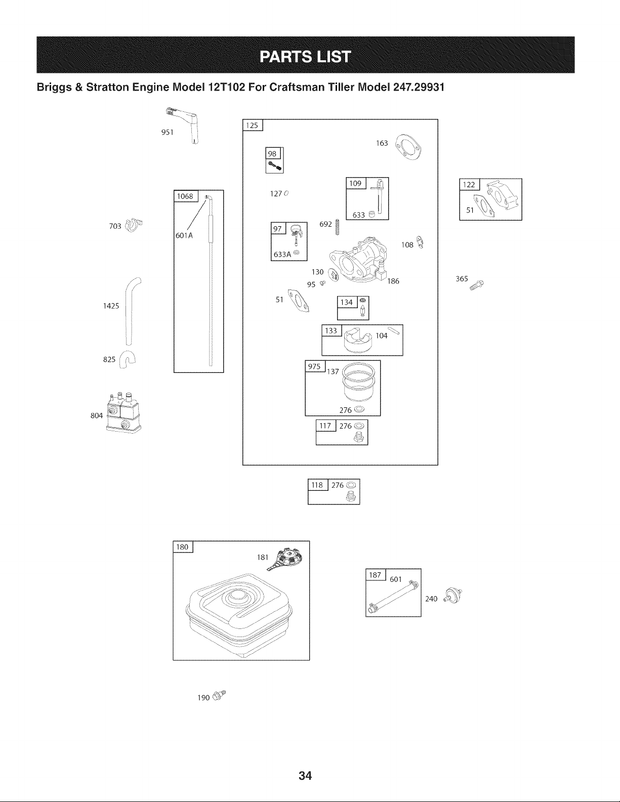
Briggs & Stratton Engine Model 12T102 For Craftsman Tiller Model 247.29931
,_)/_,,_
703 _(/_
1425 [
L9
825 _
804
951
601A
127(_
51
163
0921
lO8_)
276 IJ?)
240
190 @_
34
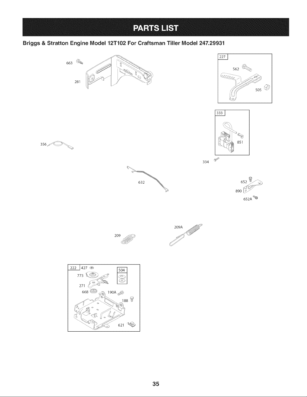
Briggs & Stratton Engine Model 12T102 For Craftsman Tiller Model 247.29931
663
281
562 'i_
334
652A %
209
22 1427 _
773
621
35
Briggs & Stratton Engine IViodel 12T102 For Craftsman Tiller IViodel 247.29931
951 i i 968
161
163
11
836A
36
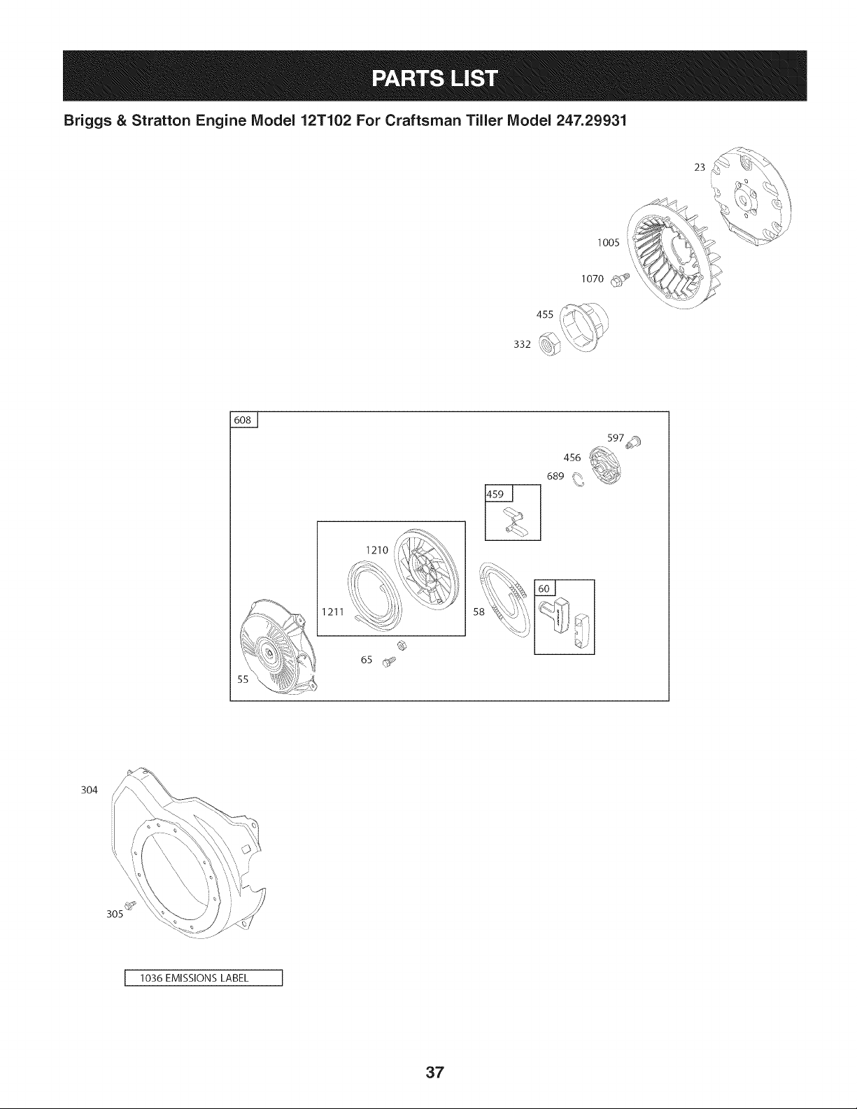
Briggs & Stratton Engine Model 12T102 For Craftsman Tiller Model 247.29931
23
lO7O;_ _
/
332
1211
1210
I
456
689 _
304
I 1036 EMISSIONS LABEL I
37
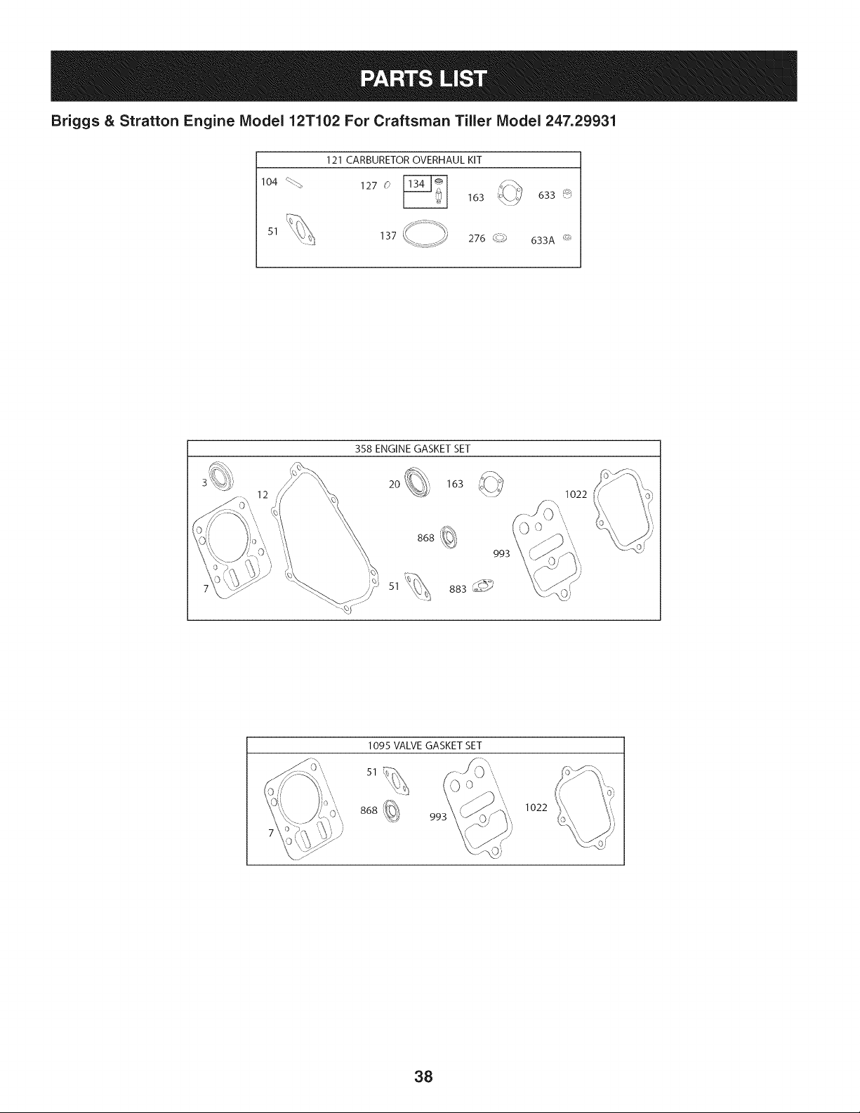
Briggs & Stratton Engine Model 12T102 For Craftsman Tiller Model 247.29931
104 %_,
51
121 CARBURETOR OVERHAUL KIT
127 0
163 633 _
633A _
358 ENGINE GASKET SET
20 163
868
51
993
883 _?_
1095 VALVE GASKET SET
51 _)\
868
0
99Z
1022
38

Briggs & Stratton Engine IViodel 12T102 For Craftsman Tiller IViodel 247.29931
|= o* |- 0=
699510 CylinderAssembly 690024 Shaft-Throttle
2 399269 Kit-Bushing/Seal(MagnetoSide) 98 398185 Kit-IdleSpeed
3 299819s Seal-Oil(MagnetoSide)
5 797439 Head-Cylinder
7 698210 Gasket-CylinderHead
11 790632 Tube-Breather
12 699485 Gasket-Crankcase
104 691242 Pin-FloatHinge
108 692567 Valve-Choke
109 790624 Shaft-Choke
117 498978 Jet-Main(Standard)
118 498975 Jet-Main(HighAltitude)
Screw(CylinderHead)
Plug-OilDrain
Plug-OilDrain
Crankshaft
Cover-Crankcase
Seal-Oil(PTOSide)
281658s Cap-OilFill
699478 LScrew(CrankcaseCover/Sump)
699488 Flywheel
222698s Key-Flywheel
795429 PistonAssembly(Standard)
121 792006 Kit-CarburetorOverhaul
122 795208 Spacer-Carburetor
125 791077 Carburetor
127 691739 Plug-Welch
130 691181 Valve-Throttle
133 398187 Float-Carburetor
134 398188 Kit-Needle/Seat
137 693981 Gasket-FloatBowl
146 690979 Key-Timing
155 797442 Plate-CylinderHead
161 795231 Base-AirCleaner
13 699482
15 691686
15A .691682
16 797074
18 699696
20 692550
21
22
23
24
25
-- 795430 PistonAssembly(.020"Oversize)
26 791969 RingSet (Standard)
-- 791969 RingSet (.020"Oversize)
27 691866 Lock-PistonPin
28 499423 Pin-Piston
29 690124 Rod-Connecting
30 791584 Dipper-ConnectingRod
32 .691664 J Screw(ConnectingRod) (Short)
163 696024 Gasket-AirCleaner
180 795705 Tank-Fuel
181 795221 Cap-FuelTank
186 692317 Hose-Connector
187 791766 Line-Fuel(Cutto RequiredLength)
188 699479 Screw(ControlBracket)
190 699220 Screw(FuelTank)
190A 795047 Screw(FueITank)
32A 695759 Screw(ConnectingRod)(Long)
33 499642 Valve-Exhaust
34 795443 Valve-Intake
35 691304 Spring-Valve(Intake)
36 691304 Spring-Valve(Exhaust)
40 692194 Retainer-Valve
45 690977 Tappet-Valve
46 693404 Camshaft
192 797440 Adjuster-RockerArm
209 691278 Spring-Governor(Platinum)
209A 692571 Spring-Governor
219 693578 Gear-Governor
220 691724 Washer(GovernorGear)
222 795669 Bracket-Control
227 794367 Lever-GovernorControl
238 691300 Cap-Valve
48 N/A ShortBlock
51 692555 Gasket-Intake
55 791848 Housing-RewindStarter
58 693389 Rope-Starter
60 490652 Grip-StarterRope
65 699228 Screw(RewindStarter)
95 691636 Screw(ThrottleValve)
39
240 394358s Filter-Fuel
271 694256 Lever-Control
276 271716 Washer-Sealing
281 793133 Panel-Control
300 693593 Muffler
304 795219 Housing-Blower
305 699480 Screw(BlowerHousing)

Briggs & Stratton Engine IViodel 12T102 For Craftsman Tiller IViodel 247.29931
D = 0 0
795334 Shield-Cylinder
307 699483 Screw(CylinderShield)
332 792723 Nut(Flywheel)
333 796964 Armature-Magneto
334 699477 Screw(MagnetoArmature)
337 491055s Plug-Spark
356 692390 Wire-Stop
358 791797 GasketSet-Engine
365 699484 Screw(Carburetor)
415 693463 Plug
427 694255 Nut(ControlBracket)
445 491588s Filter-AirCleanerCartridge
455 692591 Cup-Flywheel
456 692299 Plate-PawlFriction
459 281505s PawI-Ratchet
504 694254 WasherSet
505 691251 Nut(GovernorControl Lever)
522 697689 Plug-Dipstick/Fill
552 692346 Bushing-GovernorCrank
562 691119 Bolt(GovernorControlLever)
597 691696 Screw(PawlFrictionPlate)
601 791850 Clamp-Hose(Green)
601A 795230 Clamp-Hose
608 795930 Starter-Rewind
613 791972 Screw(Muffler)
615 692576 Retainer-GovernorShaft
616 692547 Crank-Governor
619 699230 Screw(CylinderHeadPlate)
621 692310 Switch-Stop(Brake)
632 693408 Spring/Link-MechanicalGovernor
633 693867 SeaI-Choke/ThrttleShaft (Choke)
633A 691321 SeaI-Choke/ThrttleShaft (Throttle)
635 692076 Boot-SparkPlug
652 699230 Screw(SupportBracket)
652A 699755 Screw(SupportBracket)
663 699206 Screw(ControlPanel)
668 694257 Spacer
689 691855 Spring-Friction
692 690572 Spring-Detent
703 795222 Clip
718 690959 Pin-Locating
D = O O
695087 Gear-Timing
742 692564 Retainer-ERing
746 790278 Gear-Idler
773 694258 Retainer
804 795223 Canister-Carbon(EVAP)
825 795226 Hose-Air
830 797441 Stud-RockerArm
832 693583 Guard-Muffler
836 699632 Screw(MufflerGuard)
836A 699203 Screw(MufflerGuard)
851 493880s Terminal-SparkPlug
868 795440 Seal-Valve
883 691893 Gasket-Exhaust
890 790203 Bracket-Support
914 699480 Screw(RockerCover)(Bottom)
914A 797444 Screw(RockerCover)
951 790630 Lever-Choke
967 493537s Filter-AirCleanerFoam
968 791082 Cover-AirCleaner
975 796611 Bowl-Fuel
993 694088 Gasket-CylinderHeadPlate
1005 692592 Fan-Flywheel
1022 691890 Gasket-RockerCover
1023 499924 Cover-Rocker
1026 790287 Rod-Push
1029 797443 Arm-Rocker
1034 691343 Guide-PushRod
1036 Label-Emissions(Availablefroma
Briggs& StrattonDealer)
1058 277040 Operator'sManual
1068 795229 Hose/ClampAssembly
1070 699201 Screw(FlywheelFan)
1095 791798 GasketSet-Valve
1210 791849 Pulley/SpringAssembly(Pulley)
1011 791849 Pulley/SpringAssembly(Spring)
1329 12T102-0937-F8 ReplacementEngine
1330 276781 RepairManual
1395 690370 Screw(Air CleanerBase)
1425 795227 Hose-PurgeLine
4O
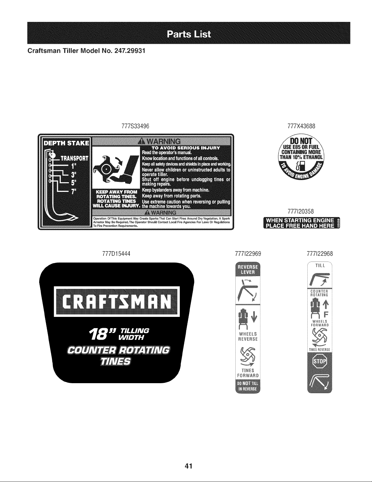
Craftsman Tiler IViodel No. 247.29931
777S33496 777X43688
777120358
777D15444 777122969 777122968
TllES
FORWARD
COUNYER i
ROTATIN{}
WIII£ S
FIIWAII
41
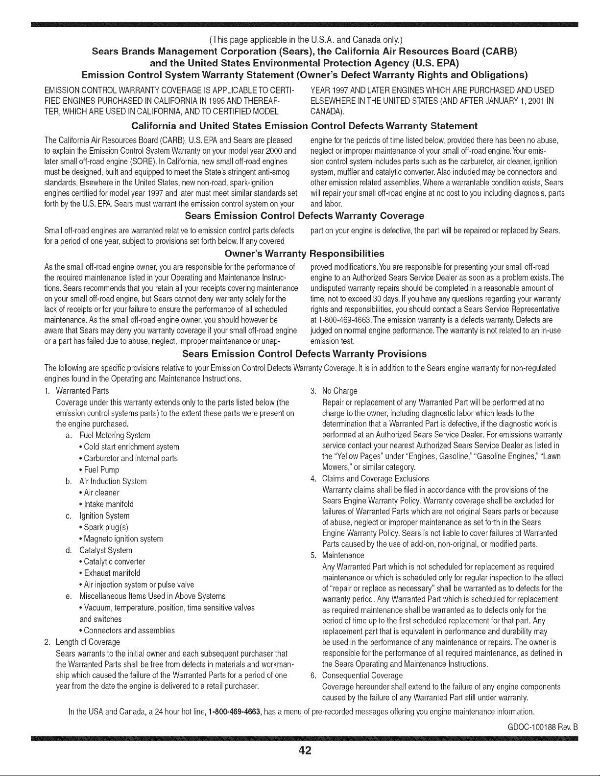
(Thispageapplicablein the U.S.A.and Canadaonly.)
Sears Brands Management Corporation (Sears), the California Air Resources Board (CARD)
and the United States Environmental Protection Agency (U.S. EPA)
Emission Control System Warranty Statement (Owner's Defect Warranty Rights and Obligations)
EMISSIONCONTROLWARRANTYCOVERAGEISAPPLICABLETO CERTI-
FIED ENGINESPURCHASEDIN CALIFORNIAIN 1995ANDTHEREAF-
TER,WHICHARE USEDINCALIFORNIA,ANDTO CERTIFIEDMODEL
California and United States Emission
The CaliforniaAir ResourcesBoard(CARD),U.S.EPAand Searsare pleased
to explainthe EmissionControlSystemWarrantyon your modelyear2000and
latersmalloff-roadengine(SORE).InCalifornia,newsmall off-roadengines
mustbe designed,builtand equippedto meetthe State'sstringentanti-smog
standards.Elsewherein the UnitedStates, newnon-road,spark-ignition
enginescertifiedfor modelyear 1997and latermustmeetsimilarstandardsset
forth bythe U.S.EPA.Sears mustwarrantthe emissioncontrol systemon your
YEAR 1997AND LATERENGINESWHICHARE PURCHASEDAND USED
ELSEWHEREIN THE UNITEDSTATES(ANDAFTERJANUARY1,2001 IN
CANADA).
Control Defects Warranty Statement
enginefor the periodsoftime listedbelow,providedthere has been noabuse,
neglector impropermaintenanceof your smalloff-roadengine.Youremis-
sion controlsystem includespartssuch as the carburetor,air cleaner,ignition
system,mufflerand catalyticconverter.Also includedmay be connectorsand
otheremissionrelatedassemblies.Wherea warrantableconditionexists,Sears
will repairyour smalloff-roadengineat no costto you includingdiagnosis,parts
and labor.
Sears Emission Control Defects Warranty Coverage
Smalloff-roadenginesarewarrantedrelativeto emissioncontrol partsdefects
fora period of one year,subjectto provisionsset forth below.Ifany covered
Owner's Warranty
Asthe smalloff-roadengine owner,you are responsiblefor the performanceof
therequiredmaintenancelistedin yourOperatingand MaintenanceInstruc-
tions.Searsrecommendsthat you retain all yourreceiptscoveringmaintenance
on yoursmalloff-roadengine,butSears cannotdenywarrantysolelyfor the
lackof receiptsor for yourfailureto ensurethe performanceof all scheduled
maintenance.As the smalloff-roadengineowner,you shouldhoweverbe
awarethat Searsmay denyyou warrantycoverageif your smalloff-roadengine
ora part hasfailed dueto abuse,neglect,impropermaintenanceor unap-
parton yourengineis defective,the part will be repairedor replacedbySears.
Responsibilities
provedmodifications.Youare responsiblefor presentingyour smalloff-road
engineto an AuthorizedSearsServiceDealeras soonas a problemexists.The
undisputedwarrantyrepairsshouldbe completedin a reasonableamountof
time,not to exceed30 days. Ifyou haveany questionsregardingyourwarranty
rightsand responsibilities,you shouldcontacta SearsService Representative
at 1-800-469-4663.The emissionwarrantyis a defectswarranty.Defectsare
judged on normalengineperformance.The warrantyis not relatedto an in-use
emissiontest.
Sears Emission Control Defects Warranty Provisions
ThefollowingarespecificprovisionsrelativetoyourEmissionControlDefectsWarrantyCoverage.Itisin additiontotheSearsenginewarrantyfornon-regulated
enginesfoundin theOperatingand MaintenanceInstructions.
1. WarrantedParts
Coverageunderthis warrantyextendsonly to the parts listedbelow (the
emissioncontrolsystemsparts)to the extentthese partswere presenton
theengine purchased.
a. FuelMeteringSystem
•Cold start enrichmentsystem
•Carburetorand internalparts
•FuelPump
b. Air lnductionSystem
•Air cleaner
•Intakemanifold
c. IgnitionSystem
•Spark plug(s)
•Magnetoignitionsystem
d. CatalystSystem
•Catalyticconverter
•Exhaustmanifold
•Air injectionsystemor pulsevalve
e. MiscellaneousItemsUsedin AboveSystems
•Vacuum,temperature,position,timesensitivevalves
andswitches
• Connectorsandassemblies
2. Lengthof Coverage
Searswarrantsto the initialownerand eachsubsequentpurchaserthat
the WarrantedPartsshallbe free from defects in materialsand workman-
shipwhich causedthefailure of the WarrantedPartsfor a periodof one
yearfrom the datethe engineis deliveredto a retailpurchaser.
3. NoCharge
Repairor replacementof anyWarrantedPartwill beperformedat no
chargeto the owner,includingdiagnosticlabor whichleadsto the
determinationthata WarrantedPartis defective, if the diagnosticwork is
performedat an AuthorizedSears ServiceDealer.For emissionswarranty
servicecontact yournearestAuthorizedSears ServiceDealeras listed in
the "YellowPages"under"Engines,Gasoline,""GasolineEngines,""Lawn
Mowers,"orsimilar category.
4. Claimsand CoverageExclusions
Warrantyclaimsshall be filed in accordancewith the provisionsof the
Sears EngineWarrantyPolicy.Warrantycoverageshall be excludedfor
failuresof WarrantedPartswhichare not original Sears partsor because
of abuse,neglector impropermaintenanceas setforth inthe Sears
EngineWarrantyPolicy.Sears is not liableto coverfailuresof Warranted
Partscausedby the use of add-on,non-original,or modifiedparts.
5. Maintenance
Any WarrantedPart whichis notscheduledfor replacementas required
maintenanceor whichis scheduledonly for regularinspectionto the effect
of "repairor replaceas necessary"shallbe warrantedas to defectsfor the
warrantyperiod.Any WarrantedPartwhich is scheduledfor replacement
as requiredmaintenanceshallbe warrantedas to defectsonly forthe
periodof time up to the first scheduledreplacementfor that part.Any
replacementpart that is equivalentin performanceand durabilitymay
be usedin the performanceof any maintenanceor repairs.The owneris
responsibleforthe performanceof all requiredmaintenance,as definedin
the SearsOperatingand MaintenanceInstructions.
6. ConsequentialCoverage
Coveragehereundershallextend to thefailure of any enginecomponents
caused bythe failureof any WarrantedPartstill underwarranty.
Inthe USAandCanada,a 24 hour hotline, 1-800-469-4663,has a menu of pre-recordedmessagesofferingyou enginemaintenanceinformation.
GDOC-100188Rev.B
42
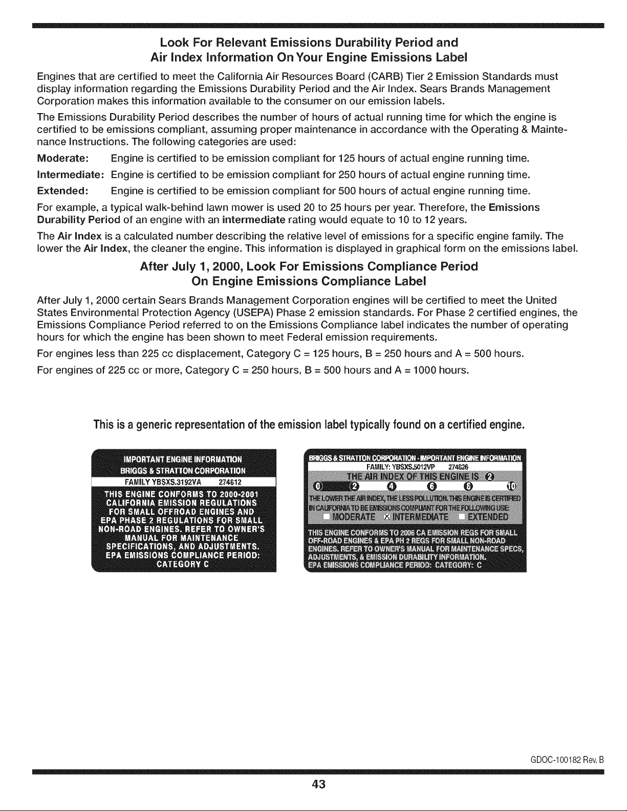
Look For Relevant Emissions Durability Period and
Air index information On Your Engine Emissions Label
Engines that are certified to meet the California Air Resources Board (CARB) Tier 2 Emission Standards must
display information regarding the Emissions Durability Period and the Air Index. Sears Brands Management
Corporation makes this information available to the consumer on our emission labels.
The Emissions Durability Period describes the number of hours of actual running time for which the engine is
certified to be emissions compliant, assuming proper maintenance in accordance with the Operating & Mainte-
nance Instructions. The following categories are used:
Moderate: Engine is certified to be emission compliant for 125 hours of actual engine running time.
Intermediate: Engine is certified to be emission compliant for 250 hours of actual engine running time.
Extended: Engine is certified to be emission compliant for 500 hours of actual engine running time.
For example, a typical walk-behind lawn mower is used 20 to 25 hours per year. Therefore, the Emissions
Durability Period of an engine with an intermediate rating would equate to 10 to 12 years.
The Air index is a calculated number describing the relative level of emissions for a specific engine family. The
lower the Air Index, the cleaner the engine. This information is displayed in graphical form on the emissions label.
After July 1,2000, Look For Emissions Compliance Period
On Engine Emissions Compliance Label
After July 1, 2000 certain Sears Brands Management Corporation engines will be certified to meet the United
States Environmental Protection Agency (USEPA) Phase 2 emission standards. For Phase 2 certified engines, the
Emissions Compliance Period referred to on the Emissions Compliance label indicates the number of operating
hours for which the engine has been shown to meet Federal emission requirements.
For engines less than 225 cc displacement, Category C = 125 hours, B = 250 hours and A = 500 hours.
For engines of 225 cc or more, Category C = 250 hours, B = 500 hours and A = 1000 hours.
This is ageneric representation of the emission label typically found on a certified engine.
FAMILYYBSXS.3192VA 274812
GDOC-100182Rev.B
43
Congratulations on making a smart purchase. Your new Craftsman® product is designed and
manufactured for years of dependable operation. But like all products, it may require repair
from time to time. That's when having a Repair Protection Agreement can save you money and
aggravation.
Here's what the Repair Protection Agreement* includes:
[] Expert service by our 10,000 professional repair specialists
[] Unlimited service and no charge for parts and labor on all covered repairs
[] Product replacement up to $1500 if your covered product can't be fixed
[] Discount of 25% from regular price of service and related installed parts not covered by the
agreement; also, 25% off regular price of preventive maintenance check
[] Fast help by phone - we call it Rapid Resolution - phone support from a Sears representative.
Think of us as a "talking owner's manual."
Once you purchase the Repair Protection Agreement, a simple phone call is all that it takes for you
to schedule service. You can call anytime day or night, or schedule a service appointment online.
The Repair Protection Agreement is a risk-free purchase. If you cancel for any reason during the
product warranty period, we will provide a full refund. Or, a prorated refund anytime after the
product warranty period expires. Purchase your Repair Protection Agreement today!
Some limitations and exclusions apply. For prices and additional information in the U.S.A.
call 1=800=827=6655.
*Coverage in Canada varies on some items. For full details call Sears Canada at 1=800=361=
6665.
Sears Installation Service
For Sears professional installation of home appliances, garage door openers, water heaters, and
other major home items, in the U.S.A. or Canada call 1=800=4=MY=HOME®.
44
Declaraci6n de garantia ........................ P_,gina 45
Medidas importantes de seguridad ..... P_,ginas 46-49
Armado ................................................. P_,ginas 50-51
Funcionamiento .................................... P_,ginas 52-59
Servicio y Mantenimiento ..................... P_.ginas 60-65
Almacenamiento fuera de temporada.. P_,gina 66
Soluci6n de problemas ......................... P_,gina 67
Acuerdo de protecci6n para reparaciones P_,gina 71
NQmero de servicio ............................... Cubierta posterior
CRAFTSMAN DOS AltOS DE GARANTIA
Durantedos aSosdesdela fechade compra,este productoest_ garantizadocontracualquierdefectode materialeso manodeobra. Un
productodefectuosorecibir_la reparaci6no sustituci6ngratuitasi la reparaci6nnoest_disponible.
Paradetalles sobre la garantia de coberturapara obtener reparaci6ngratuita o reemplazo,visite el sitio web: www.craftsman.com
Esta garantias61ocubre defectos en rnateriaiesy mano de obra. Cobertura de lagarantiano ineiuye:
• Bienesfungiblesque puedendesgastarsecon el usonormalenel periodode garantia,comolas cuchillas,dientes,o cinturones.
• DaSosenel productoresultantede los intentosdel usuariode modificaci6ndel productoo la reparaci6no causadospor accesoriosde
productos.
• Las reparacionesnecesariasdebidoa un accidenteo falla paraoperaro mantenerel productoseg0nlas instruccionessuministradas.
• Mantenimientopreventivoo reparacionesnecesariasdebidoa la mezclade combustibleinadecuado,eJcombustiblecontaminadoo viciado.
Estagaranfiaser_nulasi el productoes utilizadoalgunavez, mientrasquela prestaci6nde servicioscomercialo si se alquilaa otra persona.
Estagaranfiale otorgaderechoslegalesespecificos,y ustedtambi_npuedetenerotrosderechosquevariande estadoa estado.
Sears Brands Management Corporation, Hoffman Estates, IL 60179
Seriedel motor:
Tipode aceite del motor:
Capacidadde aceitedel motor:
Combustible:
Bujia:
Separaci6nde las bujias:
205cc
SAE3O
20onzas
Gasolinasin plomo
Champion@RC-12YC
.030"
NSmerode modelo ..........................................................
NSmerode serie ..............................................................
Fechade compra .............................................................
Registreel nOmerode modelo,nQmerode serie
y fechade compram_s arriba
© KCD IR LLC 45
Lapresenciadeestesimboloindicaquesetratadeinstruccionesde
seguridadimportantesquesedebenrespetarparaevitarponerenpeligro
suseguridadpersonaly/omaterialyladeotraspersonas.Leaycumpla
todaslasinstruccionesdeestemanualantesdeintentaroperaresta
m&quina.Sinorespetaestasinstruccionespuedeprovocarlesiones
personales.Cuandoveaestesimbolo,ipresteatenci6nalaadvertencia!
Estam&quinaest&diseSadaparaserutilizadarespetandolasnormas
deseguridadcontenidasenestemanual.AIigualqueconcualquiertipo
deequipomotorizado,undescuidooerrorporpartedeloperadorpuede
producirlesionesgraves.Estam_quinaescapazdeamputardedos,
manosypiesydearrojarresiduos.Denorespetarlasinstruccionesde
seguridadsiguientessepuedenproducirlesionesgravesolamuerte.
PROPOSICION 65 DE CALiFORNiA
El escapedel motorde este producto,algunos de sus componentesy
algunoscomponentesdel vehiculocontieneno liberansustanciasquimicas
que el estadode Californiaconsideraque puedenproducircancer,
defectosde nacimientou otrosproblemasreproductivos.Los homes de la
bateriay los accesoriosalines contienenplomoy compuestosde plomo,
sustanciasquimicasque segQnIo establecidopor el Estadode California
causanc&ncery daSosen el sistemareproductivo.L&veselas manos
despuesde estar en contacto con estoscomponentes.
Su responsabilidad--Lirnite el uso deestarn_.quinarnotorizada
alas personasque lean,cornprendany curnplanlas advertenciase
instruccionesque aparecenen este manualyen larn_.quina.
i6UARI)E ESTASINSTRUCCIONES!
CAPACITACION
• Lea,cornprenday respetetodas las instruccionesquefiguranen
la rn_.quinayen el o los rnanualesantesde procedera arrnarlay
hacerlafuncionar.Guardeeste manualen un lugarseguropara
consultasfuturasy peri6dicas,asi cornoparasolicitarrepuestos.
• Leael manualdeloperadory sigatodaslas advertenciase
instruccionesde seguridad.De no hacerlo,puedeocasionar
heridasde gravedadal operadory/oa los observadores.Ante
cualquierduda,Ilarneal 1-800-4MY-HOME.
•Farniliaricesecontodoslos controlesy su correcto
funcionarniento.Sepac6rnodetenerla rn_.quinay c6rno
desconectarloscontrolesr_.pidarnente.
• No perrnitanuncaque losni_os rnenoresde 14a_osutilicen
estarn_.quina.Los ni_osde 14a_osen adelantedebenleery
entenderlas instruccionesde operaci6ny norrnasdeseguridad
contenidasen este manualyen larn_.quinay debenser
entrenadosy supervisadospor un adulto.
•Nuncaperrnitaque losadultosoperenesta rn_quinasin recibir
antesla instrucci6napropiada.
• Mantengaa los observadores,rnascotasy ni_osal rnenosa 25
metrosde la rn_.quinarnientrasest,. en funcionarniento.Detenga
la rn_.quinasi alguienseacerca.
• Nuncaenciendael motoren espacioscerradoso en una zona
con pocaventilaci6n.El escapedel motorcontienernon6xidode
carbono,un gasinodoroy letal.
PREPARATIVOS
•Reviserninuciosarnenteel &readondese va a usarel equipo.
Retiretodaslas piedras,botellas,latasy otrosobjetosextra_os
que puedanserlevantadoso arrojadoscausandolesiones
personaleso da_osa la rn_.quina.
•Paraprotegerselosojos, utilice siernpregalas o anteojosde
seguridadrnientrasoperala rn_.quinao rnientraslaajustao
repara.Losobjetosarrojadosquerebotanpuedenproducir
lesionesocularesgraves.
•Utilicezapatosde trabajoresistentes,desuelafuerte,y
pantalonesy carnisasajustados.Las prendassueltasy las
alhajasse puedenengancharen las piezasrn6viles.Nuncaopere
estarn_.quinaestandodescalzoo con sandalias.
•Antesde encenderla rn_quinacontroleque todos los pernosy
tornillosest_nbienajustadospara garantizarque la rn_.quinase
encuentraen condicionessegurasde operaci6n.Adern_.s,realice
una inspecci6nvisualde la rn_.quinaa intervalosfrecuentespara
controlarsi la rnisrnaest,. da_ada.
•Antesde arrancarel motor,desenganchelas palancasdel
ernbraguey despl_.celas(en casode haber)a la posici6nneutral
("N").
•Nuncadejelarn_.quinaen funcionarnientosin vigilancia.
•Nuncaintenterealizarajustesrnientrasel motorest,. en rnarcha,
exceptoen los casosespedficarnenterecornendadosenel
manualdel operador.
•Mantengao reernplacelas etiquetasde seguridade instrucciones
segQnsea necesario.
46
Manejo seguro de la gasolina:
Paraevitar lesionespersonalesy da_os materialestenga muchocuidado al
manipularla gasolina.La gasolinaes sumamenteinflamabley sus vapores
puedencausarexplosiones.Si se derramagasolinaencimao sobre la ropa
se puedelesionargravementeya que se puedeincendiar. Lavesela piely
c_mbiesede ropade inmediato.
• Utilices61olosrecipientespara gasolinaautorizados.
• Nunca Ilenelosrecipientesen el interiorde un vehiculoo cami6n o
cajade remolquecon un recubrimientopl_stico.Coloquesiemprelos
recipientesen el pisoy lejosdel vehiculo antes de Ilenarlos.
• Cuandosea factible,retireel equipo a gasolinadel cami6no remolquey
Ileneloen el suelo.Si esto no es posible,Ilene el equipoen un remolque
con contenedorport_til,en vezde desdeuna boquilladispensadorade
gasolina.
• Mantengala boquillaen contactocon el hordedel tanquede
combustibleo de la abertura del recipienteen todo momento,hasta
terminarde cargar.No utilice un dispositivopara abrir/cerrarla boquilla.
• Apaguetodos los cigarrillos,cigarros,pipasy otrasfuentesde
combusti6n.
• Nunca carguecombustibleen la m_quinaen un espacio cerrado.
• Nuncasaquela tapade la gasolinani agreguecombustiblemientrasel
motorest_ calienteo en marcha.Permitaque el motorse enfrie pot Io
menosdos minutosantesde volver a cargar combustible.
• Nuncalleneen excesoel tanquede combustible.Lleneel tanque no
m_sde Y2pulgadapor debajo de la basedel cuello del tap6n de carga,
para dejarespacio para la expansi6ndel combustible.
• Vuelvaa colocarla tapadel combustibley ajOstelabien.
• Limpiela gasolinaquese puedahaberderramadosobreel motoro el
equipo.Trasladela m_quinaa otra zona.Espere5 minutosantesde
encenderel motor.
• Para reducirel riesgode incendio,mantengala m_quinalimpiade
pasto,hojas y de acumulaci6nde otrosescombros.Limpie los derrames
de aceite o combustibley saque todoslos escombrosembebidosde
combustible.
• Nuncaguardela m_quinao el recipientede combustibleen un espacio
cerradodonde hayafuego, chispas o luz piloto,como porejemplo de
calentadoresde agua, calefactoresde ambientes,hornos,secadoresde
ropa u otros aparatosa gas.
FUNCIONAlVlIENTO
•Nocoloque las manosni los piescerca de piezasgiratorias.Elcontacto
con las piezasgiratoriaspuede ocasionaren la amputaci6nde manos
o pies.
• No utilicela m_quinabajo la influenciadel alcoholo las drogas.
• Nunca opereestam_quinasi no hay buenavisibilidado iluminaci6n.
Siempredebe estarsegurode queest_ bienafirmado y sujetando
firmementelas manijas.
• Mantengaa los transeL]ntesalejadosde la m_quinamientrasla misma
est_ en funcionamiento.Detengala m_quinasi alguiense acerca.
• Tengacuidado al labrarun terrenoduro.Los dientes puedenclavarseen
latierra e impulsar lacultivadorahacia adelante.Si esto ocurre, suelteel
manubrioy deje la m_quinalibre.
• Sea sumamenteprecavidocuandoopere la m_quinasobre una
superficiecon grava o al cruzarla.Mantengasealerta por si se
presentanpeligrosocultoso tr_nsito.Notransporte pasajeros.
• Nuncautilicela m_quinaa altasvelocidadesde desplazamientosobre
superficiesduras o resbaladizas.
• Tengacuidado para evitarresbalaro caerse.
• Mire haciaabajo y haciaarrasy tenga cuidadocuandose desplaceen
marchaarraso cuandojale de la m_quinahaciausted.
• Arranqueel motorde acuerdocon lasinstruccionesdel manual y aleje
los piesde losdientesen todo momento.
•Si golpeaalgQnun objeto extra_oo si la m_quinacomienzaa emitir
un sonidopococomL]no a vibrar, apagueel motorde inmediato.
Desconecteel cable de labujia, p6ngalohaciendomasacontrael motor
y siga los pasossiguientes:
a. Inspeccionela m_quinapara vet si est_ da6ada.
b. Repareo reemplacelas piezasda_adas.
c. Controle si hay piezasflojas y ajQstelaspara asegurarque la
m_quinafuncionede maneraseguray continua.
• Desenganchetodaslas palancasde embrague(si lashay)y detengael
motorantes de dejar la posici6nde operaci6n(detr_sde las manijas).
Esperehastaque los dientesse detengancompletamenteantes de
limpiarlos,haceralgQnajusteo inspeccionarlos.
• Nuncaenciendael motoren espacioscerradoso en unazonacon poca
ventilaci6n.El escape del motorcontienemon6xidode carbono, un gas
inodoroy letal.
• El silenciadory el motorse calientany puedencausarquemaduras.No
lostoque.
• Tengaprecauci6ncuandolabreterrenocercade vallas,edificios y
servicios subterr_neos.Los dientesrotatoriospuedencausar daSos
materialeso lesionespersonales.
• Nosobrecarguela capacidadde la m_quinaintentandolabrarel sueloa
un niveldemasiadoprofundoo a unavelocidaddemasiador@ida.
• Si la m_quinaarrancahaciendoun sonidoo unavibraci6nrata, detenga
el motor,desconecteel cable de la bujia y con@telo a masacontra el
motor.Inspeccionela m_quinaminuciosamenteparaver si est_ da6ada.
Reparetodos los da_osantes de encendery operar la m_quina.
• Mantengatodos los escudos,protectoresy dispositivosde seguridaden
su lugar yen correctofuncionamiento.
• Nuncalevanteo transportela m_quinacuandoel motorest_ encendido.
• Utilices61odispositivosde sujeci6no accesoriosaprobadosporel
fabricanteque figuranen laspaginasde la listade piezasdeeste
manualdel operador.Si no Io hace,puedenproducirselesiones
personales.
• Si se presentansituacionesque no est_n previstasen estemanual,sea
cuidadosoy useel sentido comL]n.P6ngaseen contactocon Asistencia
al Cliente parasolicitar ayuday el hombredel distribuidorde servicio
m_scercano.
iVlANTENllVIIENTO YALIViACENAIVlIENTO
•Mantengala m_quina,losaditamentosy accesoriosen condicionesde
funcionamientoseguro.
• Deje quela m_quinase enfrie por Io menoscincominutosantes
de guardarla.Nuncaaltere los dispositivosde seguridad.Controle
peri6dicamentequefuncionancorrectamente.
• Verifiquefrecuentementeque los pernosy tornillosestenajustados
correctamenteparaasegurarsede que la m_quinaeste trabajandode
manerasegura.Adem_s,hagaunainspecci6nvisualde lam_quinapara
verificarsi est_da_ada.
• Antesde limpiar,repararo revisar,detengael motory asegQresede que
los dientesy todas las partesm6vilesse hartdetenido.Desconecteel
cable de la bujia y p6ngalohaciendomasacontrael motorpara evitarque
se enciendaaccidentalmente.
• Nocambielaconfiguraci6ndel reguladordel motor niIo hagafuncionar
a demasiadavelocidad.Elreguladordel motorcontrolala velocidad
m_ximade funcionamientosegurodel motor.
• Mantengao reemplacelas etiquetasde seguridady de instrucciones
segQnsea necesario.
• Siga las instruccionesde este manual paracargar,descargar,transportar
y almacenarde maneraseguraesta m_quina.
• Si la m_quinase va a almacenarpor un periodo prolongado,consulte
siempreel manualdel operadorpara obtenerinformaci6nimportante.
• Si debevaciareltanquede combustible,h_galoalaire libre.
47
,, Observelareglamentaci6nylasnormasrespectoalaeliminaci6n
correctadegasolina,aceite,etc.paraprotegerelmedicambiente.
• SegQnlaComisi6ndeSeguridaddeProductosparaelConsumidorde
losEstadosUnidos(CPSC)ylaAgenciadeProtecci6nAmbientaldelos
EstadosUnidos(EPA),esteproductotieneunavidaQtilmediadesiete
(7)a_os6130horasdefuncionamiento.AIfinalizarlavidaQtilmedia
hagainspeccionaranualmenteestaunidadporundistribuidordeservicio
autorizadoparacerciorarsedequetodoslossistemasmec_nicosyde
seguridadfuncionancorrectamenteynotienenexcesivodesgaste.Sino
Iohace,puedenproducirseaccidentes,lesionesolamuerte.
NO MODIFIQUE EL MOTOR
Para evitarlesionesgraveso la muerte,no modifiqueel motorbajo ninguna
circunstancia.Si altera la configuraci6ndel regulador,el motorse puede
desbocary funcionar a velocidadesqueno son seguras. Nuncamodifiquela
configuraci6nde f_brica del reguladordel motor.
AVISO REFERIDO AEMISIONES
Los motoresque est_ncertificadosy cumplencon las regulacionesde
emisionesfederales EPAy de Californiapara SORE (EquiposSmall Off Road
Equipment)est_ncertificados para operarcon gasolinacomL]nsin plomoy
pueden incluirlos siguientessistemasde controlde emisiones: Modificaci6n
de motor(EM), catalizadoroxidante(OC), inyecci6nde airesecundaria(SAI)
y catalizadorde tres vias (TWO)si est_nequipadosde esa manera.
AMORTIGUADOR DE CHISPAS
Esta m&quinaest&equipadacon un motorde combusti6ninternay no
debeser utilizadaen un terrenoagrestecubiertopot bosque,malezaso
hierbani cercadel mismoexceptoque el sistemade escapedel motor
este equipadocon un amortiguadorde chispas quecumpla con las leyes
localeso estatalescorrespondientes(encaso de existir).
Si se utilizaun amortiguadorde chispasel operadorIo debe manteneren
condicionesde uso adecuadas.En el Estadode Californialas medidas
anteriormentemencionadasson exigidas por ley (Arficulo4442del C6digode
RecursosPQblicosde California).Es posibleque existanleyessimilaresen
otros estados. Las leyesfederalesse aplicanen territoriosfederales.
Podr_obtener un amortiguadorde chispasparael silenciadoren el centrode
servicio de piezasy reparacionesSears m_scercano.
48
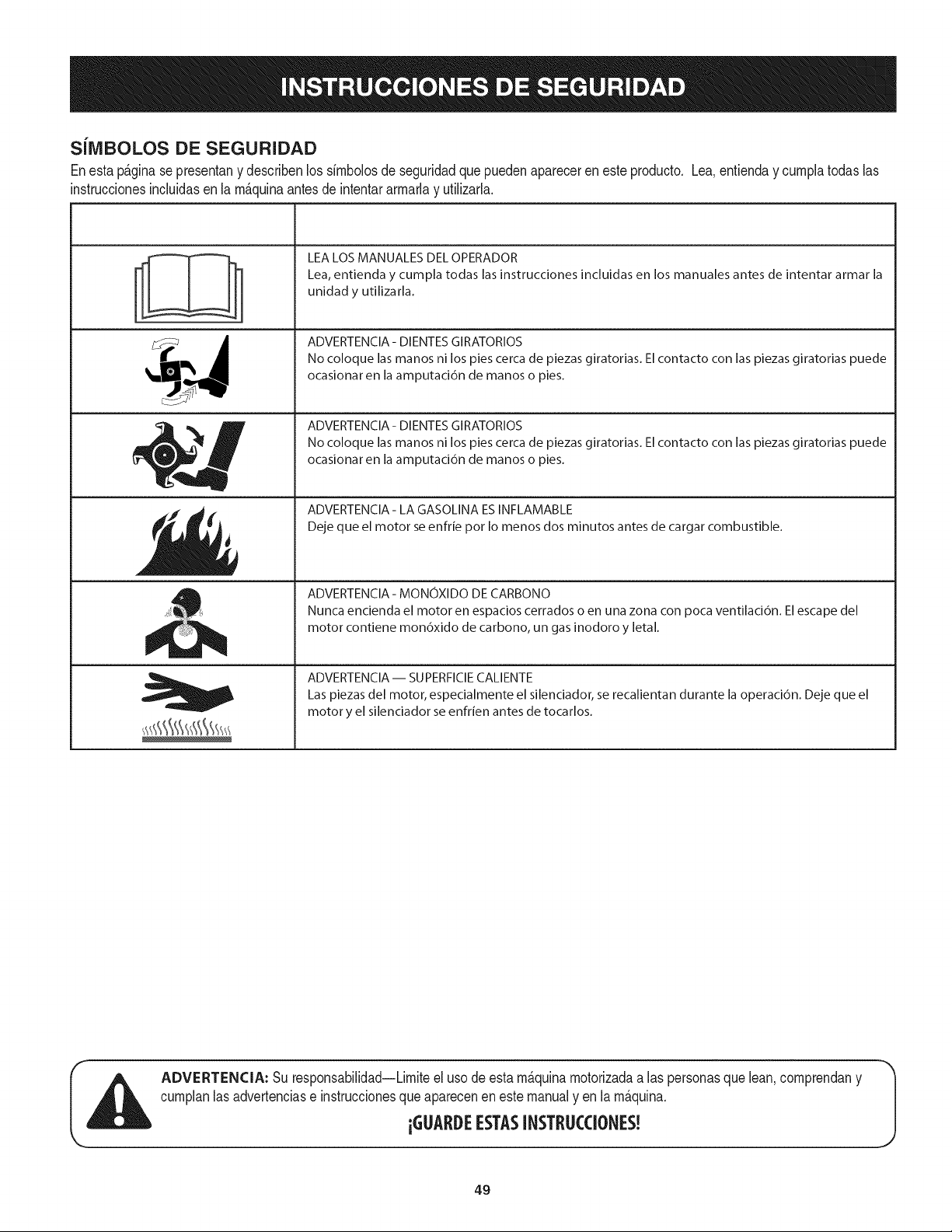
SiIVIBOLOS DE SEGURIDAD
Enestap&ginase presentany describenlos simbolosde seguridadque puedenapareceren esteproducto. Lea,entienday cumplatodaslas
instruccionesincluidasen la m_quinaantesdeintentararmarlay utilizarla.
-'I °_
I I
I I
t i
i
, i
LEA LOS MANUALES DEL OPERADOR
Lea, entienda y cumpla todas las instrucciones incluidas en los manuales antes de intentar armar la
unidad y utilizarla.
ADVERTENCIA- DIENTES GIRATORIOS
No coloque las manos ni los pies cerca de piezas giratorias. El contacto con las piezas giratorias puede
ocasionar en la amputaci6n de manos o pies.
ADVERTENCIA- DIENTES GIRATORIOS
No coloque las manos ni los pies cerca de piezas giratorias. El contacto con las piezas giratorias puede
ocasionar en la amputaci6n de manos o pies.
ADVERTENClA- LA GASOLINA ESINFLAMABLE
Deje que el motor se enfrie pot Io menos dos minutos antes de cargar combustible.
ADVERTENCIA - MONOXIDO DE CARBONO
Nunca encienda el motor en espacios cerrados o en una zona con poca ventilaci6n. El escape del
motor contiene mon6xido de carbono, un gas inodoro y letal.
ADVERTENCIA- SUPERFIClE CALIENTE
Las piezas del motor, especialmente el silenciador, se recalientan durante la operaci6n. Deje que el
motor y el silenciador se enfrien antes de tocarlos.
ADVERTENCIA: Su responsabilidad--Limiteel uso deestam_quinamotorizadaa las personasque lean,comprendany
cumplanlas advertenciase instruccionesqueaparecenen este manualy en la m_quina.
iGUARDEESTASINSTRUCCIONES!
49
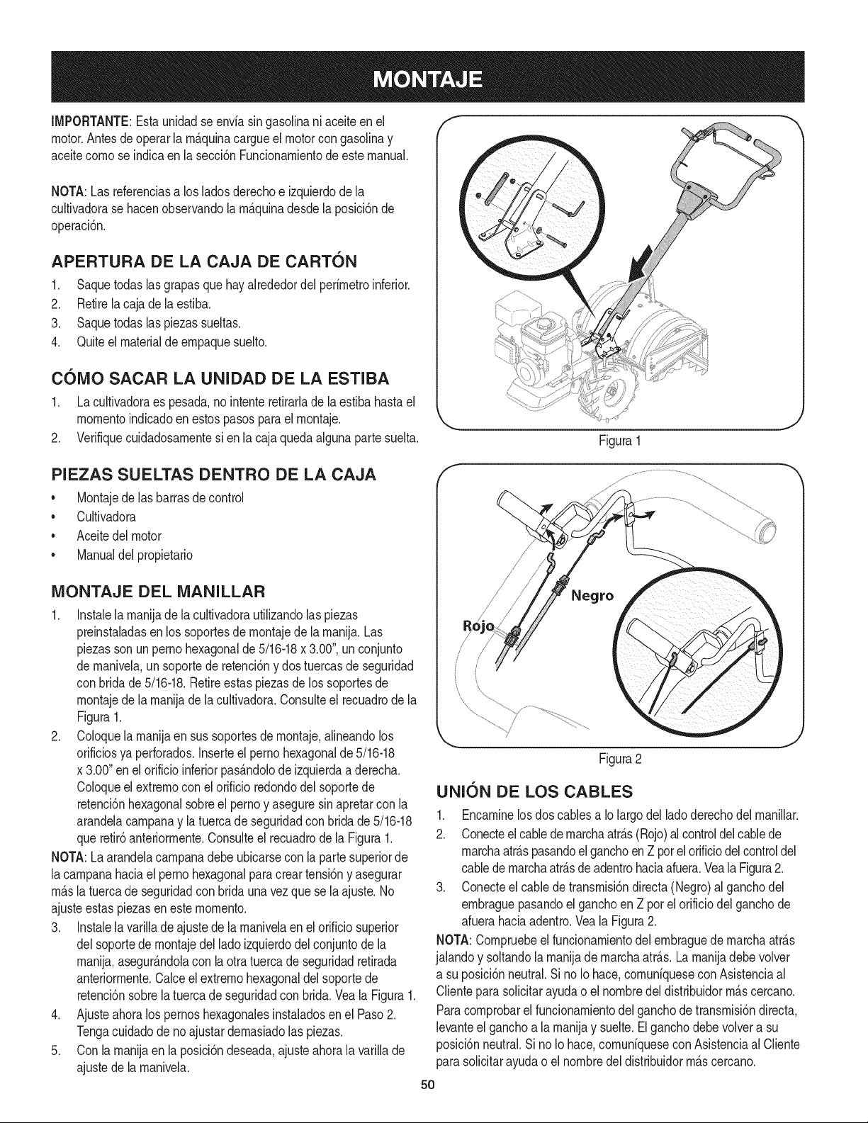
IMPORTANTE:Estaunidadse enviasin gasolinani aceiteen el
motor,Antesde operarla rn_.quinacargueel motorcon gasolinay
aceitecornose indicaenla secci6nFundonarnientode este manual,
NOTA:Las referenciasa los ladosderechoe izquierdode la
cultivadorase hacenobservandolarn_.quinadesdela posici6nde
operaci6n.
APERTURA DE LA CAJA DE CARTON
1. Saquetodas lasgrapasque hayakededordel perirnetroinferior.
2. Retirela cajade laestiba.
3. Saquetodaslaspiezas sueltas.
4. Quiteel materialdeempaquesuelto.
COIVIO SACAR LA UNIDAD DE LA ESTIBA
1. La cultivadoraes pesada,no intenteretirarlade la estiba hastael
rnornentoindicadoen estospasosparael rnontaje.
2. Verifiquecuidadosarnentesi enla cajaquedaalgunapartesuelta. Figura1
PIEZAS SUELTAS DENTRO DE LA CAJA
•Montajede las barrasde control
• Cultivadora
• Aceitedel motor
• Manualdel propietario
iVIONTAJE DEL iVlANILLAR
1. Instalelarnanijadela cultivadorautilizandolaspiezas
preinstaladasen los soportesde rnontajede la rnanija.Las
piezasson unpernohexagonalde5/16-18x 3.00",unconjunto
de rnanivela,unsoportede retenci6ny dos tuercasde seguridad
con bridade 5/16-18.Retireestas piezasdelos soportesde
rnontajede la rnanijade la cultivadora.Consulteel recuadrodela
Figura1.
2. Coloquela rnanijaen sus soportesde rnontaje,alineandolos
orificiosya perforados.Inserteel pernohexagonalde 5/16-18
x 3.00"en el orificioinferiorpas_.ndolode izquierdaa derecha.
Coloqueel extrernocon el orificio redondodel soportede
retenci6nhexagonalsobreel pernoy aseguresin apretarcon la
arandelacarnpanay la tuercade seguridadcon bridade5/16-18
queretir6anteriorrnente.Consulteel recuadrode la Figura1.
NOTA:La arandelacarnpanadebeubicarsecon la partesuperiorde
lacarnpanahaciael pernohexagonalpara creartensi6ny asegurar
rn_.slatuercadeseguridadcon bridauna vez que se la ajuste.No
ajusteestaspiezasen este rnornento.
3. Instalelavarillade ajuste de la rnanivelaen elorificiosuperior
delsoportede rnontajedel lado izquierdodel conjuntode la
rnanija,asegur_.ndolacon la otratuercade seguridadretirada
anteriorrnente.Calceel extrernohexagonaldelsoportede
retenci6nsobrela tuercade seguridadcon brida.Veala Figura1.
4. Ajusteahoralos pernoshexagonalesinstaladosen el Paso2.
Tengacuidadode no ajustardernasiadolas piezas.
5. Con la rnanijaen la posici6ndeseada,ajusteahora la varillade
ajustede larnanivela.
f
/
J
Figura2
UNION DE LOS CABLES
1. Encarninelosdos cablesa Io largodel ladoderechodelrnanillar.
2. Conecteel cabledernarchaatr_.s(Rojo)al controldel cablede
rnarchaatr_.spasandoel ganchoenZ porelorificiodelcontroldel
cablede rnarchaatrAsdeadentrohaciaafuera.Vea la Figura2.
3. Conecteel cablede transrnisi6ndirecta (Negro)al ganchodel
ernbraguepasandoel ganchoen Z pot el orificiodel ganchode
afuerahaciaadentro.Veala Figura2.
NOTA:Cornpruebeelfuncionarnientodel ernbraguede rnarchaatrAs
jalandoy soltandola rnanijadernarchaatrAs.La rnanijadebevolver
a su posici6nneutral.Sino Io hace,cornuniqueseconAsistenciaal
Clienteparasolicitarayudao el nornbredeldistribuidorrn_.scercano.
Paracornprobarel funcionarnientodelganchodetransrnisi6ndirect&
levanteel ganchoa la rnanijay suelte.Elganchodebevolvera su
posici6nneutral.Si noIo hace,cornuniqueseconAsistenciaal Cliente
parasolicitarayudao el nornbredel distribuidorrn_.scercano.
50
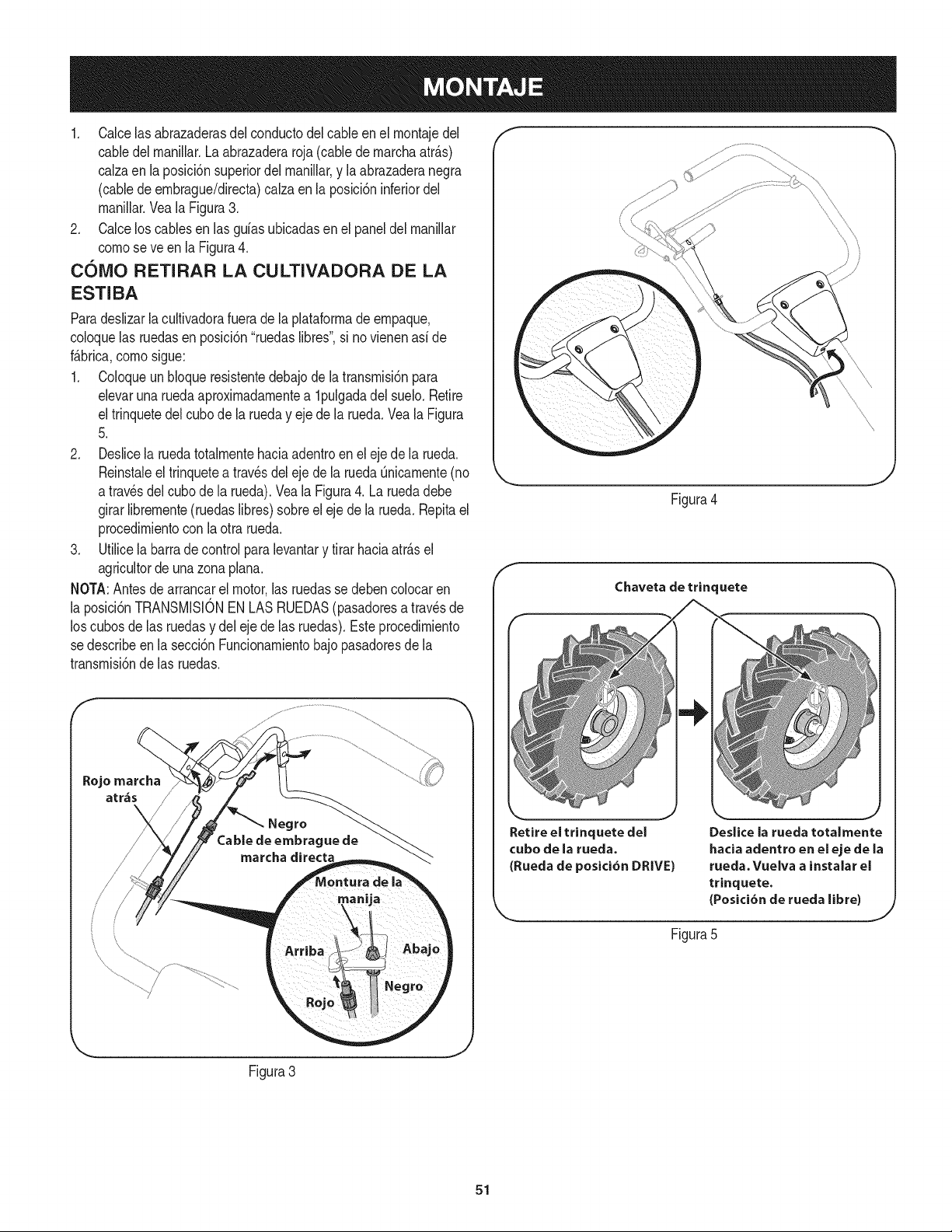
1. Calcelas abrazaderasdel conductodelcableen el rnontajedel
cabledel rnanillar.La abrazaderaroja(cablede rnarchaatr_.s)
calzaen la posici6nsuperiordel rnanillar,y la abrazaderanegra
(cablede ernbrague/directa)calzaen la posici6ninferiordel
rnanillar.Vea la Figura3.
2. Calcelos cablesen las guiasubicadasen el paneldel rnanillar
comese ve en la Figura4.
come RETIRAR LA CULTIVADORA DE LA
ESTIBA
Paradeslizarla cultivadorafuerade laplataforrnade ernpaque,
coloquelas ruedasenposici6n"ruedaslibres",si novienenasi de
f_.brica,comesigue:
1. Coloqueun bloqueresistentedebajodela transrnisi6npara
elevaruna ruedaaproximadarnentea lpulgada del suelo. Retire
el trinquetedelcubede la rueday ejede larueda.Veala Figura
5.
2. Deslicela ruedatotalrnentehaciaadentroen el eje de la rueda.
Reinstaleel trinquetea travesdel eje de la rueda Qnicarnente(no
a travesdel cubede la rueda).Veala Figura4. La ruedadebe
girarlibrernente(ruedaslibres)sobreeleje dela rueda.Repitael
procedirnientocon laotra rueda.
3. Utilicela barradecontrolparalevantary tirar haciaatr_.sel
agricultorde unazona plana.
NOTA:Antesdearrancarel motor,las ruedasse debencolocaren
la posici6nTRANSMISIONEN LAS RUEDAS(pasadoresa travesde
los cubesde las ruedasy del ejede las ruedas).Esteprocedirniento
se describeenla secci6nFuncionarnientobajo pasadoresde la
transrnisi6nde las ruedas.
Rojo marcha
arras
Figura4
Chaveta de trinquete
Retire el trinquete del
cube de la rueda.
(Rueda de posici6n DRIVE)
Deslice la rueda totalmente
hacia adentro en el eje de la
rueda. Vuelva a instalar el
trinquete.
(Posici6n de rueda libre)
Figura5
Figura3
J
51
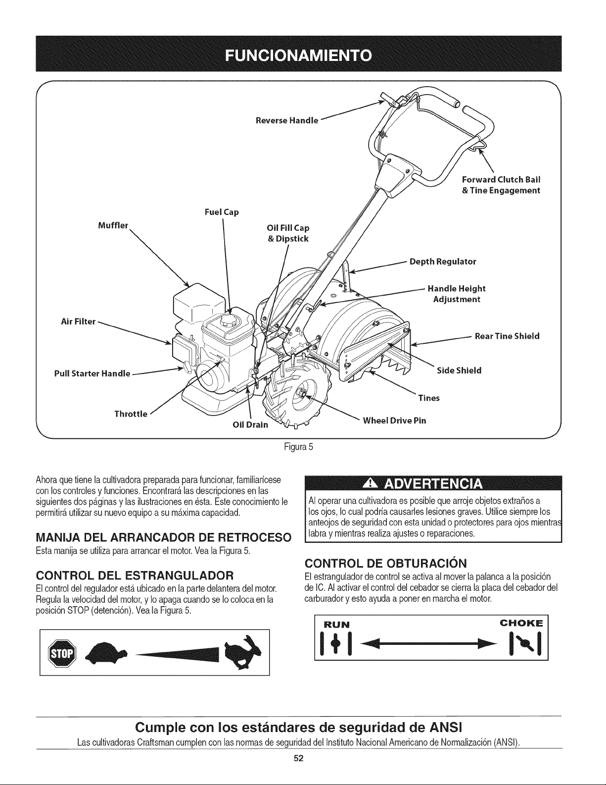
f
Reverse Handle
Fuel Cap
OU Fill Cap
& Dipstick
Depth Regulator
Forward Clutch Bail
& Tine Engagement
Air
Handle Height
Adjustment
Rear Tine Shield
Pull Starter Handle Side Shield
Throttle
Oil Drain
Tines
Wheel Drive Pin
Figura5
Ahoraquetienela cultivadorapreparadaparafuncionar,farniliaricese
conloscontrolesy funciones.Encontrar_.las descripcionesen las
siguientesdos p_.ginasy las ilustracionesen _sta.Esteconocirnientole
perrnitir_,utilizarsunuevoequipoa su rn_.xirnacapacidad.
iVlANIJA DEL ARRANCADOR DE RETROCESO
Estarnanijase utilizaparaarrancarel motor.Yeala Figura5.
CONTROL DEL ESTRANGULADOR
Elcontroldel reguladorest,.ubicadoen la partedelanteradel motor.
Regulala velocidaddelmotor,y IoapagacuandoseIo colocaen la
posici6nSTOP(detenci6n).Veala Figura5.
AI operarunacultivadoraes posibbquearrojeobjetosextra_osa
losojos,Iocual podriacausarbsbsiones graves.Utilicesiernprelos
anteojosdeseguridadconestaunidado protectoresparaojosrnientras
labray rnientrasrealizaajusteso reparaciones.
CONTROL DE OBTURACION
Elestranguladordecontrolseactivaal moverla palancaa laposici6n
de IC.AIactivarelcontroldelcebadorse cierrala placadelcebadordel
carburadory estoayudaa poneren rnarchaelmotor.
RUN CHOKE
I+1
Cumple con los estandares de seguridad de ANSI
LascultivadorasCraftsmancurnplencon lasnorrnasde seguridaddelInstitutoNacionalArnericanodeNorrnalizaci6n(ANSI).
52
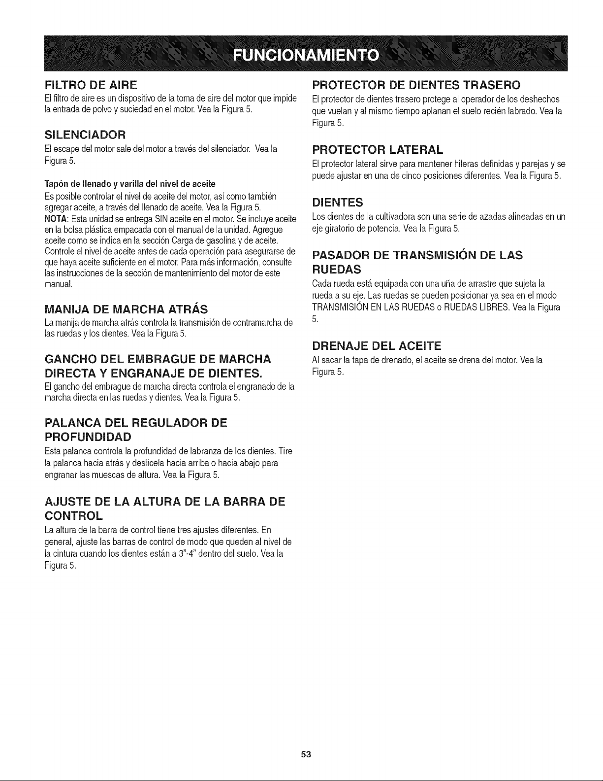
FILTRO DE AIRE
Elfiltrodeairees undispositivode latomadeairedelmotorqueimpide
laentradade polvoy suciedadenel motor.Veala Figura5.
SILENCIADOR
Elescapedel motorsaledel motora travesdel silenciador.Veala
Figura5.
Tap6nde Ilenadoyvarilla del nivel de aceite
Es posiblecontrolarel nivelde aceitedel motor,asicomotambi_n
agregaraceite,a travesdel Ilenadodeaceite.Veala Figura5.
NOTA:EstaunidadseentregaSINaceiteenel motor.Se incluyeaceite
enla bolsapl_.sticaempacadaconelmanualdela unidad.Agregue
aceitecomoseindicaen la secci6nCargade gasolinay de aceite.
Controleel niveldeaceiteantesdecadaoperaci6nparaasegurarsede
quehayaaceitesuficienteen el motor.Param_.sinformaci6n,consulte
lasinstruccionesdelasecci6nde mantenimientodel motorde este
manual.
MANIJA DE MARCHA ATRAS
Lamanijade marchaatr_.scontrolala transmisi6nde contramarchade
las ruedasy los dientes.Veala Figura5.
GANCHO DEL EMBRAGUE DE iVlARCHA
DIRECTA Y ENGRANAJE DE DIENTES,
Elganchodel embraguede marchadirectacontrolaelengranadode la
marchadirectaen lasruedasy dientes.VealaFigura5.
PROTECTOR DE DIENTES TRASERO
Elprotectorde dientestraseroprotegeal operadorde los deshechos
quevuelany al mismotiempoaplananelsuelo reci_nlabrado.Veala
Figura5.
PROTECTOR LATERAL
Elprotectorlateralsirve para mantenerhilerasdefinidasy parejasy se
puedeajustarenunade cincoposicionesdiferentes.Veala Figura5.
DIENTES
Losdientesde la cultivadorason unaseriede azadas alineadasen un
eje giratoriodepotencia.Vea la Figura5.
PASADOR DE TRANSiVlISION DE LAS
RUEDAS
Cadaruedaest,. equipadacon unau_adearrastrequesujetala
ruedaa su eje.Las ruedassepuedenposicionarya seaenel modo
TRANSMISIONEN LAS RUEDASo RUEDASLIBRES.Veala Figura
5.
DRENAJE DEL ACEITE
AI sacarlatapa dedrenado,el aceite se drenadel motor.Veala
Figura5.
PALANCA DEL REGULADOR DE
PROFUNDIDAD
Estapalancacontrolala profundidadde labranzade losdientes.Tire
la palancahaciaatr_.sy deslicelahaciaarribao haciaabajopara
engranarlas muescasde altura.Veala Figura5.
AJUSTE DE LA ALTURA DE LA BARRA DE
CONTROL
Laalturade la barrade control tienetresajustesdiferentes.En
general,ajustelas barrasdecontrolde modoque quedenal nivelde
la cinturacuandolos dientesest_.na 3"-4"dentrodel suelo.Vea la
Figura5.
53
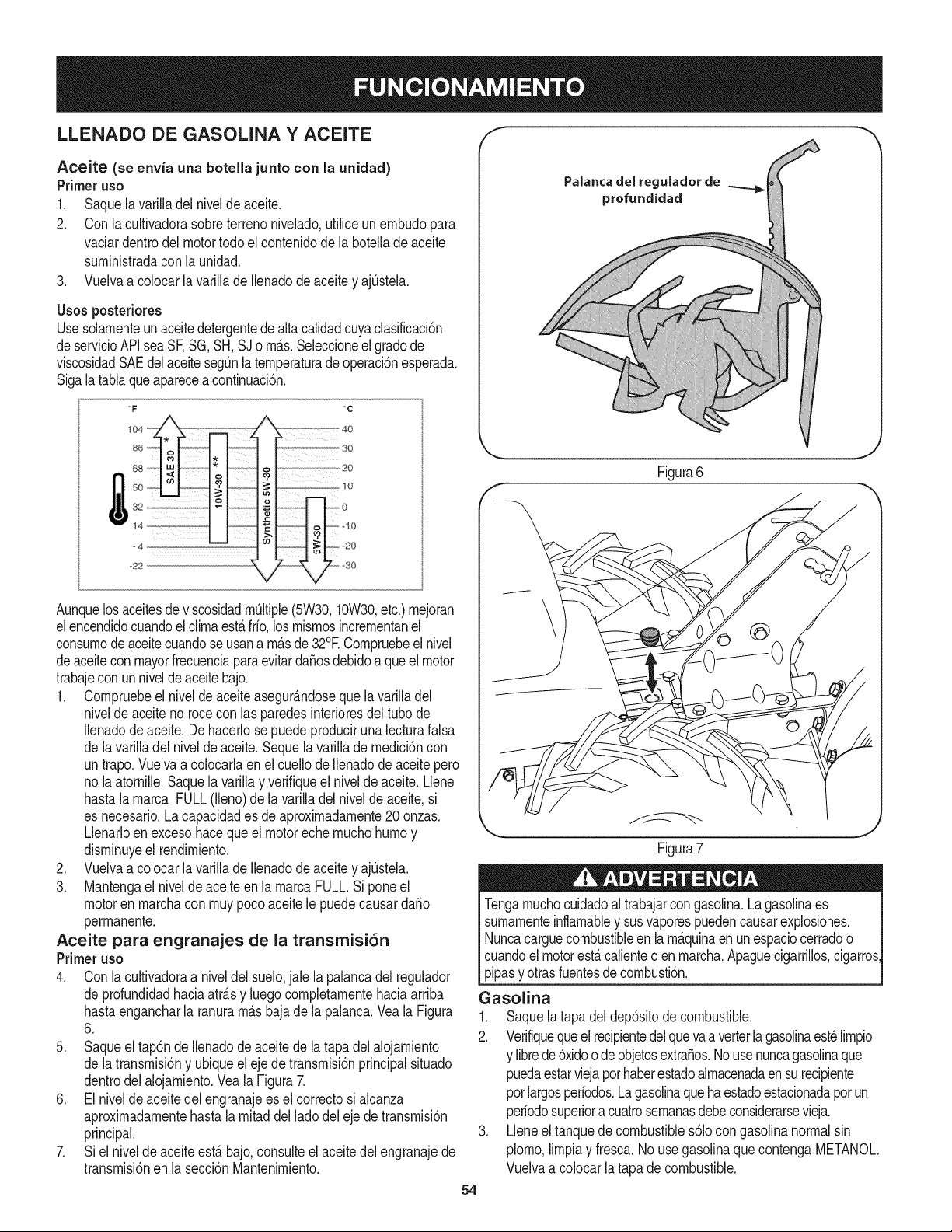
LLENADO DE GASOLINA YACEITE f "_
Aceite (se envia una botella junto con la unidad)
Primeruso
1. Saquela varilladel niveldeaceite.
2. Con la cultivadorasobreterrenonivelado,utiliceunernbudopara
vaciardentrodel motortodo el contenidodela botellade aceite
surninistradacon la unidad.
3. Vuelvaa colocarla varilladeIlenadodeaceitey ajOstela.
Usos posteriores
Usesolarnenteunaceitedetergentedealtacalidadcuyaclasificaci6n
de servicioAPIseaSF,SG,SH,SJo rn_.s.Seleccioneelgradode
viscosidadSAEdelaceitesegOnla ternperaturade operaci6nesperada.
Sigalatablaqueapareceacontinuaci6n.
oF
86
68
50
32
14
_22
oc
_20
Aunquelosaceitesde viscosidadrnOltiple(5W30,10W30,etc.)rnejoran
elencendidocuandoelclirnaest_frio,los rnisrnosincrernentanel
consurnodeaceitecuandoseusana rn_sde 32°E Cornpruebeel nivel
deaceiteconmayorfrecuenciaparaevitardafiosdebidoa queelmotor
trabajecon un niveldeaceitebajo.
1. Cornpruebeel nivelde aceiteasegur_ndosequelavarilladel
nivelde aceite no rocecon lasparedesinterioresdel tubode
Ilenadode aceite.De hacerlose puedeproduciruna lecturafalsa
de lavarilladel nivelde aceite.Seque la varillade rnedici6ncon
untrapo.Vuelvaa colocarlaen el cuellode Ilenadodeaceitepero
no laatornille.Saquela varillay verifiqueel nivelde aceite.Llene
hastalarnarca FULL(lleno)de la varilladel niveldeaceite,si
es necesario.La capacidades de aproxirnadarnente20 onzas.
Llenarloen excesohaceque el motoreche rnuchohurnoy
disrninuyeel rendirniento.
2. Vueivaa co[ocarla varillade Ilenadode aceite y ajOstela.
3. Mantengael nivelde aceiteen la rnarcaFULL.Siponeel
motoren rnarchacon rnuypocoaceite le puedecausardafio
perrnanente.
Aceite para engranajes de la transmisi6n
Primeruso
4. Con lacultivadoraa niveldel suelo,jale la palancadel regulador
de profundidadhaciaatr_sy luegocornpletarnentehaciaarriba
hastaengancharla ranurarn_sbajade la palanca.Veala Figura
6.
5. Saqueel tap6ndeIlenadode aceite de la tapa del alojarniento
de latransrnisi6ny ubiqueel eje de transrnisi6nprincipalsituado
dentrodel alojarniento.Vea la Figura7.
6. El nivelde aceitedel engranajeesel correctosi alcanza
aproxirnadarnentehastalarnitaddel lado del eje detransrnisi6n
principal.
7. Si el nivelde aceiteest_bajo,consulteel aceitedelengranajede
transrnisi6nen la secci6nMantenirniento.
Paianca del regulador de
profundidad
Figura6
\
Figura7
Tengarnuchocuidadoaltrabajarcon gasolina.La gasolinaes
surnarnenteinflarnabley susvaporespuedencausarexplosiones.
Nuncacarguecombustibleenla rn_.quinaenunespaciocerradoo
cuandoel motorest,.calienteo en rnarcha.Apaguecigarrillos,cigarros
pipasy otrasfuentesdecornbusti6n.
Gasolina
1. Saquelatapadel dep6sitode combustible.
2. Verifiquequeel recipientedelquevaa verterla gasolinaest_lirnpio
y librede6xidoo de objetosextrafios.Nousenuncagasolinaque
puedaestarviejapot haberestadoalrnacenadaensu recipiente
porlargosperiodos.La gasolinaquehaestadoestacionadaporun
periodosuperiora cuatrosernanasdebeconsiderarsevieja.
3. Lleneeltanquede combustibles61ocongasolinanormalsin
plorno,lirnpiay fresca.No usegasolinaquecontengaMETANOL.
Vuelvaa colocarla tapade combustible.
54
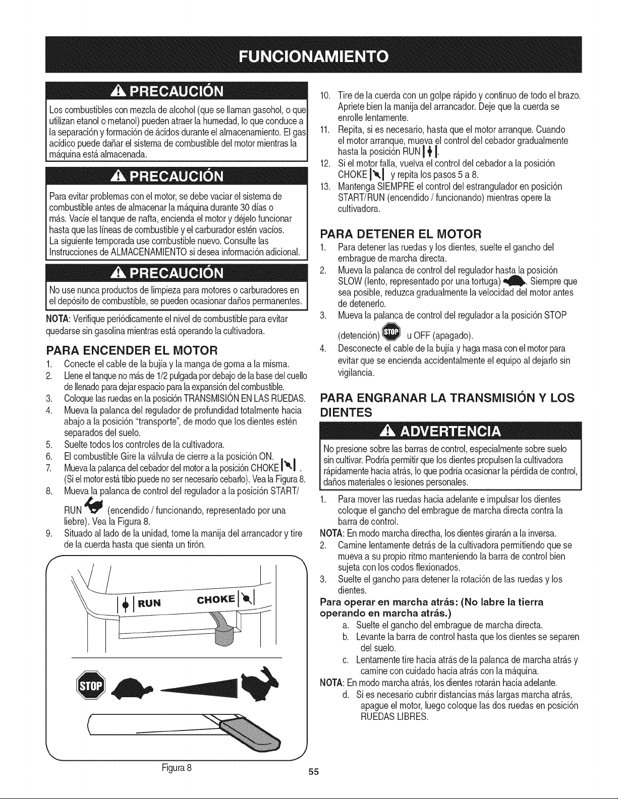
Loscombustiblescon rnezcladealcohol(que seIlarnangasohol,o que
utilizanetanolo rnetanol)puedenatraerla hurnedad,Ioqueconducea
laseparaci6ny forrnaci6nde&cidosduranteelalrnacenarniento.El gas
acfdicopuededaSarel sisternadecombustibledelmotorrnientrasla
rn&quinaest&alrnacenada.
Paraevitarproblernasconel motor,se debevaciarel sisternade
combustibleantesdealrnacenarla rnAquinadurante30 dfaso
rn_.s.Vacfeel tanquede nafta,enciendael motory d_jelofuncionar
hastaquelas Ifneasde combustibley el carburadorest_nvacfos.
Lasiguienteternporadausecombustiblenuevo.Consultelas
InstruccionesdeALMACENAMIENTOsi deseainforrnaci6nadicional.
Nousenuncaproductosde lirnpiezapararnotoreso carburadoresen
el dep6sitodecombustible,sepuedenocasionarda_osperrnanentes.
NOTA:Verifiqueperi6dicarnenteel nivelde combustibleparaevitar
quedarsesingasolinarnientrasest_operandola cultivadora.
PARA ENCENDER EL MOTOR
1. Conecteel cablede la bujfay la rnangade gornaa la rnisrna.
2. Lleneeltanqueno rn_sde1/2pulgadapotdebajodelabasedelcuello
deIlenadoparadejarespacioparala expansi6ndel combustible.
3. Coloquelasruedasen la posici6nTRANSMISlONENLASRUEDAS.
4. Muevala palancadel reguladorde profundidadtotalrnentehacia
abajoa laposici6n"transporte",de rnodoquelos dientesest_n
separadosdelsuelo.
5. Sueltetodoslos controlesde la cultivadora.
6. ElcombustibleGirela v_lvuladecierrea la posici6nON. , ,
7. Muevalapalancadelcebadordelmotora laposici6nCHOKEI&l .
(Siel motorest_tibiopuedenosetnecesariocebarlo).VealaFigura8.
8. Muevala palancade controldel reguladora la posici6nSTART/
RUN'_ (encendido/funcionando,representadoporuna
liebre).Vea la Figura8.
Situadoal lado de la unidad,tome la rnanijadel arrancadory tire
de lacuerdahastaque sienta untir6n.
jL
C
10. Tire dela cuerdaconun golper_.pidoy continuodetodoel brazo.
Aprietebien la rnanijadel arrancador.Dejequelacuerdase
enrollelentarnente.
11. Repita,si es necesario,hastaque el motorarranque.Cuando
el motorarranque,rnuevael controldel cebadorgradualrnente
hastala posici6nRUNI _tI.
12. Siel motorfalla,vuelvaelcontroldel cebadora la posici6n
CHOKEI'*-I Y repitalos pasos5 a 8.
13. MantengaSIEMPREel controldel estranguladoren posici6n
START/RUN(encendido/funcionando)rnientrasoperela
cultivadora.
PARA DETENER EL MOTOR
1. Paradetenerlas ruedasy los dientes,suelteel ganchodel
ernbraguedernarchadirecta.
2. Muevala palancade controldel reguladorhastala posici6n
SLOW(lento,representadoporunatortuga)_. Siernpreque
seaposible,reduzcagradualrnentela velocidaddelmotorantes
de detenerlo.
3. Muevala palancade controldel reguladora la posici6nSTOP
(detenci6n) u OFF(apagado).
Desconecteel cablede la bujfay hagarnasaconelmotorpara
evitarquese enciendaaccidentalrnenteel equipoal dejarlosin
vigilancia.
PARA ENGRANAR LA TRANSMISI6N Y LOS
DIENTES
No presionesobrelas barrasdecontrol,especialrnentesobresuelo
sincultivar.Podrfaperrnitirque losdientespropulsenla cultivadora
rApidarnentehaciaatr_s,Ioquepodrfaocasionarlaperdidade control,
da_osrnaterialeso lesionespersonales.
1. Paramoverlas ruedashaciaadelantee irnpulsarlosdientes
coloqueel ganchodelernbraguedernarchadirectacontra la
barradecontrol.
NOTA:Enrnodornarchadirectha,losdientesgirar_na lainversa.
2. CarninelentarnentedetrAsde la cultivadoraperrnitiendoque se
rnuevaa su propio ritrnornanteniendola barrade controlbien
sujetaconlos codos flexionados.
3. Suelteel ganchopara detenerla rotaci6nde las ruedasy los
dientes.
Para operar en marcha arras: (No labre la tierra
operando en marcha arras.)
a. Suelteel ganchodel ernbraguede rnarchadirecta.
b. Levantelabarradecontrolhastaquelos dientesse separen
delsuelo.
c. Lentarnentetire haciaatr_.sde la palancade rnarchaatr_s y
carnineconcuidadohaciaatr_scon la rn_.quina.
NOTA:Enrnodornarchaatr_s,los dientesrotar_nhaciaadelante.
d. Sies necesariocubrirdistanciasrn_.slargasrnarchaatr_s,
apagueel motor,luegocoloquelas dos ruedasen posici6n
RUEDASLIBRES.
J
Figura8 55
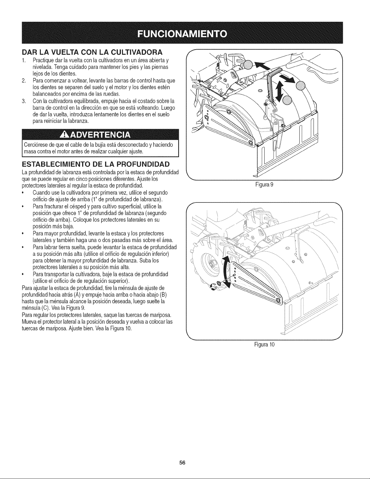
DAR LA VUELTA CON LA CULTIVADORA
1. Practiquedarla vueltacon la cultivadoraen un _.reaabiertay
nivelada.Tengacuidadoparamantenerlos pies y las piernas
lejosde losdientes.
2. Paracomenzara voltear,levantelas barrasdecontrolhastaque
los dientesse separendel sueloy el motory losdientesest_n
balanceadosporencimade las ruedas.
3. Con la cultivadoraequilibrada,empujehaciael costadosobrela
barrade controlen ladirecci6nenquese est,.volteando.Luego
dedar lavuelta,introduzcalentamentelos dientesen elsuelo
parareiniciarla labranza.
Cercbresedequeelcablede labujiaest,.desconectadoy haciendo
masacontrael motorantesderealizarcualquierajuste.
ESTABLECIMIENTO DE LA PROFUNDIDAD
Laprofundidadde labranzaestAcontroladaporla estacade profundidad
quesepuederegularen cincoposicionesdiferentes.Ajustelos
protectoreslateralesal regularlaestacade profundidad.
• Cuandouse la cultivadorapor primeravez,utiliceel segundo
orificiode ajustedearriba(1"de profundidadde labranza).
• Parafracturarel c_spedy paracultivosuperficial,utilice la
posici6nqueofrece1"de profundidaddelabranza(segundo
orificiode arriba).Coloquelos protectoreslateralesen su
posici6nm_.sbaja.
• Paramayorprofundidad,levantela estacay los protectores
lateralesy tambienhagauna o dos pasadasm_.ssobreel Area.
• Paralabrartierrasuelta,puedelevantarlaestacadeprofundidad
a su posicidnm_.salta (utiliceel orificiode regulacidninferior)
paraobtenerla mayorprofundidadde labranza.Subalos
protectoreslateralesa su posici6nm_.salta.
• Paratransportarla cultivadora,baje la estacade profundidad
(utiliceel orificiode de regulaci6nsuperior).
Paraajustarlaestacade profundidad,tirelam_nsuladeajustede
profundidadhaciaatr_.s(A)y empujehaciaarribao haciaabajo(B)
hastaquela m_nsulaalcancelaposici6ndeseada,luegosueltela
m_nsula(C).Veala Figura9.
Pararegularlos protectoreslaterales,saquelastuercasde mariposa.
Muevael protectorlaterala la posici6ndeseaday vuelvaacolocarlas
tuercasde mariposa.Ajustebien.Vea la Figura10.
Figura9
Figura10
J
56
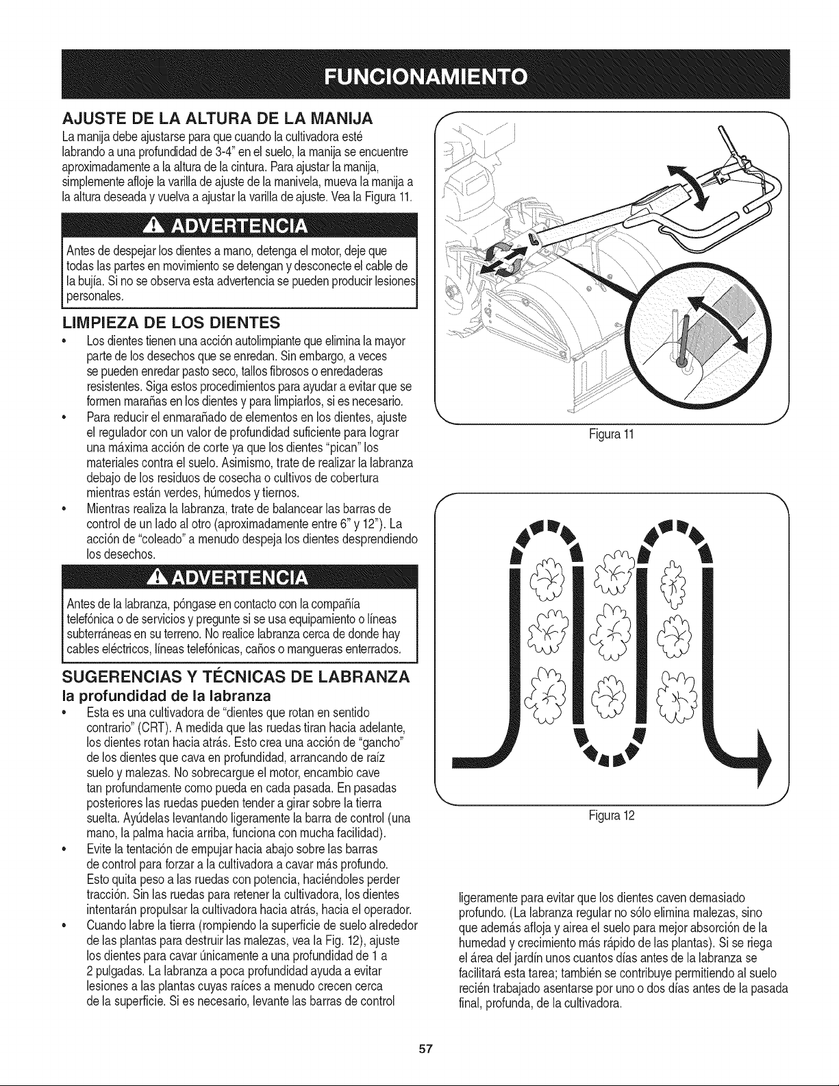
AJUSTE DE LA ALTURA DE LA MANIJA
Larnanijadebeajustarseparaque cuandolacultivadoraest_
labrandoa unaprofundidadde 3-4"enelsuelo,larnanijase encuentre
aproximadarnentea la alturadelacintura.Paraajustarla rnanija,
sirnplernenteaflojela varillade ajustede la rnanivela,rnuevala rnanijaa
laalturadeseaday vuelvaa ajustarlavarillade ajuste.VealaFigura11.
Antesdedespejarlosdientesa rnano,detengael motor,deje que
todaslaspartesen rnovirnientosedetengany desconecteel cablede
la bujfa.Si noseobservaesta advertenciase puedenproducirlesiones
personales.
LIMPIEZA DE LOS DIENTES
•Losdientestienenuna acci6nautolirnpiantequeelirninalamayor
partede losdesechosque seenredan.Sin embargo,a veces
se puedenenredarpastoseco,tallosfibrososo enredaderas
resistentes.Sigaestosprocedirnientosparaayudara evitarquese
forrnenmaracasen losdientesy paralirnpiarlos,si es necesario.
•Parareducirel enrnara_adode elernentosen losdientes,ajuste
el reguladorcon unvalorde profundidadsuficienteparaIograr
unarn_xirnaacci6n de corte ya quelos dientes"pican"los
rnaterialescontrael suelo.Asimisrno,tratede realizarla labranza
debajode los residuosdecosechao cultivosde cobertura
rnientrasestanverdes,h0rnedosy tiernos.
•Mientrasrealizala labranza,trate de balancearlas barrasde
controlde unladoalotro (aproxirnadarnenteentre6" y 12").La
acci6nde "coleado"a rnenudodespejalos dientesdesprendiendo
los desechos.
Antesde lalabranza,p6ngaseen contactocon la cornpaSia
telef6nicao de serviciosy preguntesi se usaequiparnientoo lineas
subterr&neasen suterreno.Norealicelabranzacercade dondehay
cablesel_ctricos,lineastelef6nicas,caSoso rnanguerasenterrados.
SUGERENCIAS Y Ti_CNICAS DE LABRANZA
la profundidad de la labranza
•Estaes unacultivadorade "dientesquerotanen sentido
contrario"(CRT).A rnedidaque las ruedastitan haciaadelante,
los dientesrotanhaciaatr_.s.Estocrea unaacci6nde"gancho"
delos dientesquecavaen profundidad,arrancandode rdz
sueloy rnalezas.1/osobrecargueel motor,encarnbiocave
tan profundarnentecornopuedaen cadapasada.Enpasadas
posterioreslas ruedaspuedentendera girar sobrelatierra
suelta.Ay0delaslevantandoligerarnentelabarradecontrol(una
rnano,la palrnahaciaarriba,funcionacon rnuchafacilidad).
• Evitelatentaci6nde ernpujarhaciaabajo sobrelas barras
decontrolparaforzarala cultivadoraa cavar rn&sprofundo.
Estoquita pesoalas ruedascon potencia,haci_ndolesperder
tracci6n.Sinlas ruedaspara retenerla cultivadora,losdientes
intentar&npropulsarla cultivadorahaciaatr&s,haciael operador.
• Cuandolabre la tierra (rornpiendola superficiede sueloalrededor
delas plantasparadestruirlas rnalezas,veala Fig. 12),ajuste
los dientesparacavar Onicarnentea una profundidadde 1 a
2 pulgadas.La labranzaa poca profundidadayudaa evitar
lesionesalas plantascuyasraicesa rnenudocrecencerca
dela superficie.Si es necesario,levantelas barrasde control
Figura11
f
.... J
Figura12
ligerarnenteparaevitar que los dientescavendernasiado
profundo.(Lalabranzaregularno s61oelirninarnalezas,sino
queadern&saflojay aireael suelopararnejorabsorci6nde la
hurnedady crecirnientorn_.sr&pidode las plantas).Si se riega
el _.readel jardinunoscuantosalas antesde la labranzase
facilitar&esta tarea; tarnbi_nse contribuyeperrnitiendoalsuelo
reci_ntrabajadoasentarsepot uno o dosdias antesde la pasada
final,profunda,de lacultivadora.
57
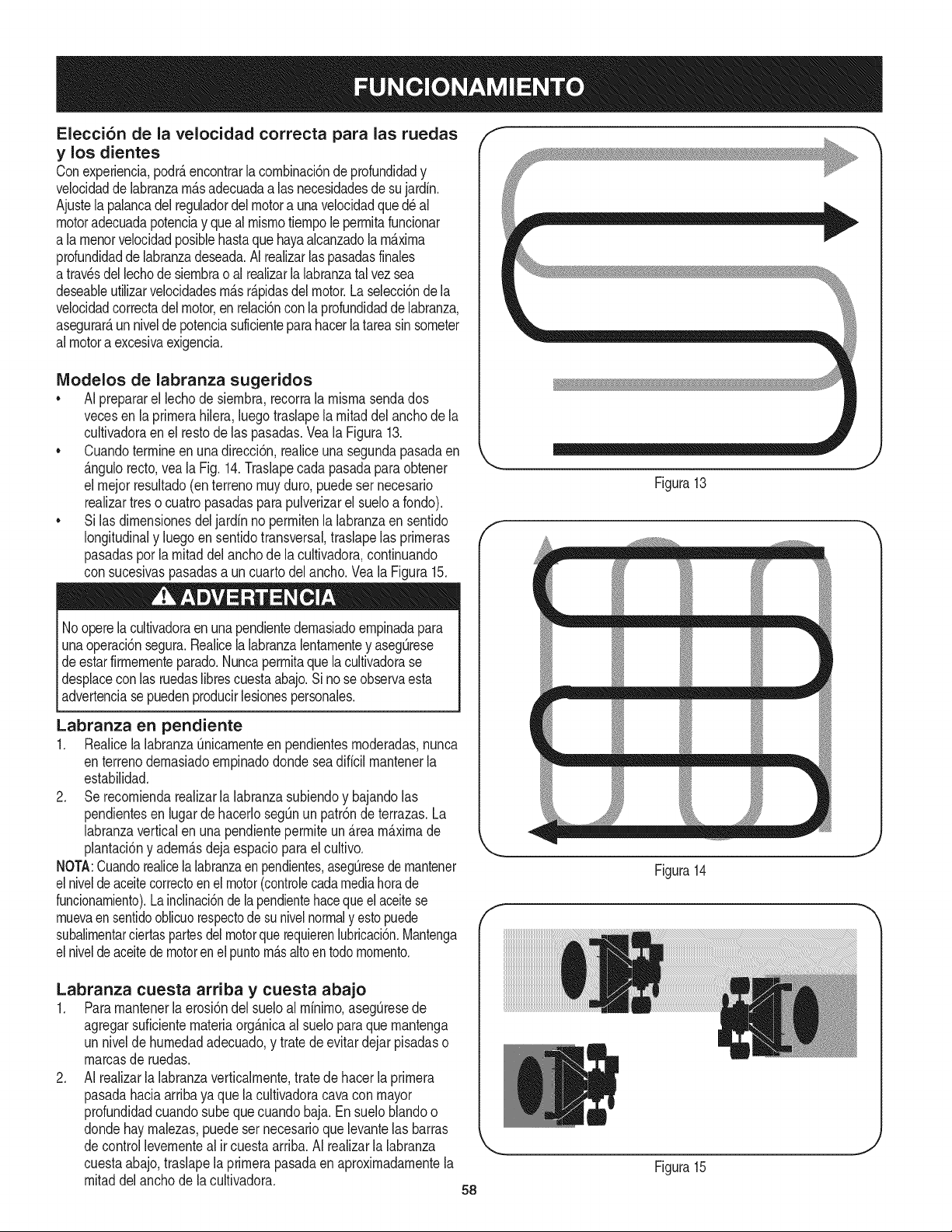
Elecci6n de la velocidad correcta para las ruedas
y los dientes
Conexperiencia,podrAencontrarlacornbinaci6ndeprofundidady
velocidadde labranzarnAsadecuadaalas necesidadesde sujardin.
Ajustela palancadel reguladordel motora unavelocidadque d_ al
motoradecuadapotenciay que al misrnotiernpole perrnitafuncionar
a larnenorvelocidadposiblehastaquehayaalcanzadola maxima
profundidadde labranzadeseada.AI realizarlaspasadasfinales
atrav_sdellechode siernbrao alrealizarla labranzatalvez sea
deseableutilizarvelocidadesrnAsrApidasdelmotor.Laselecci6nde la
velocidadcorrectadel motor,enrelaci6ncon la profundidaddelabranza,
asegurarAun nivelde potenciasuficienteparahacerlatareasinsorneter
almotoraexcesivaexigencia.
IVlodelos de labranza sugeridos
•AI prepararel lechodesiernbra,recorrala rnisrnasendados
vecesen la prirnerahilera,luegotraslapela rnitaddel anchode la
cultivadoraen el restode las pasadas.Vea la Figura13.
•Cuandoterrnineen una direcci6n,realiceunasegundapasadaen
Angulorecto,veala Fig.14.Traslapecadapasadapara obtener
el rnejorresultado(enterrenornuyduro,puedeser necesario
realizartreso cuatropasadasparapulverizarel sueloa fondo).
•Si lasdirnensionesdel jardinno perrnitenla labranzaen sentido
longitudinaly luegoensentidotransversal,traslapelas prirneras
pasadasporlarnitaddel anchode lacultivadora,continuando
con sucesivaspasadasa un cuartodel ancho. Veala Figura15.
Nooperela cultivadoraen unapendientedernasiadoernpinadapara
unaoperaci6nsegura.Realicela labranzalentarnentey asegQrese
de estarfirrnernenteparado.Nuncaperrnitaquelacultivadorase
desplacecon lasruedaslibrescuestaabajo.Si no seobservaesta
advertenciasepuedenproducirlesionespersonales.
Labranza en pendiente
1. Realicela labranzaOnicarnenteen pendientesrnoderadas,nunca
enterrenodernasiadoernpinadodondeseadificilrnantenerla
estabilidad.
2. Se recorniendarealizarla labranzasubiendoy bajandolas
pendientesen lugardehacerlosegOnun patr6nde terrazas.La
labranzaverticalen una pendienteperrniteun Areamaximade
plantaci6ny adernAsdeja espacioparael cultivo.
NOTA:Cuandorealice[alabranzaen pendientes,aseguresede rnantener
elniveldeaceitecorrectoen el motor(controlecadamediahorade
funcionarniento).Lainclinaci6ndelapendientehacequeel aceitese
rnuevaen sentidooblicuorespectode sunivelnormaly estopuede
subalirnentarciertaspartesdel motorque requierenlubricaci6n.Mantenga
elniveldeaceitedemotorenel puntornAsaltoen todornornento.
Labranza cuesta arriba y cuesta abajo
1. Pararnantener[aerosi6ndel sueloal rninirno,aseg_resede
agregarsuficienternateriaorgAnicaal sueloparaquernantenga
un nivelde hurnedadadecuado,y tratede evitardejar pisadaso
rnarcasde ruedas.
2. AI realizarla labranzaverticalrnente,tratedehacerla prirnera
pasadahaciaarriba yaque lacultivadoracavacon mayor
profundidadcuandosube quecuandobaja. En sueloblandoo
dondehay rnalezas,puedeser necesarioquelevantelas barras
decontrollevernenteal ircuestaarriba.AI realizarlalabranza
cuestaabajo,traslapela prirnerapasadaen aproxirnadarnentela
rnitaddel anchode la cultivadora. 58
f
Figura13
_ m _ m
f
Figura14
J
Figura15
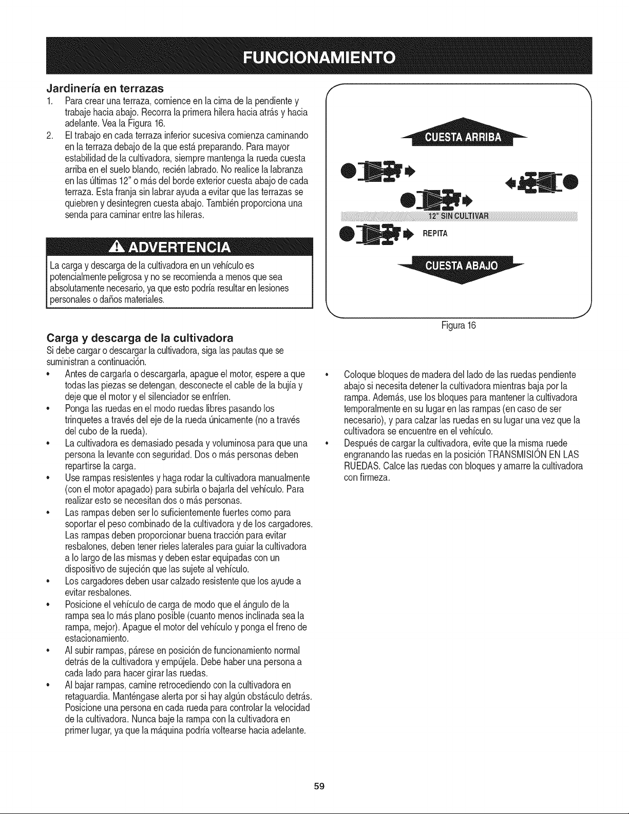
Jardineria en terrazas
1. Paracrearunaterraza,cornienceenla cirnade la pendientey
trabajehaciaabajo. Recorrala prirnerahilerahaciaatr_.sy hacia
adelante.Veala Figura16.
2. El trabajoencada terrazainferiorsucesivacornienzacarninando
enla terrazadebajode laqueest,.preparando.Paramayor
estabilidaddela cultivadora,siernprernantengala ruedacuesta
arribaen el sueloNando,reci_nlabrado.No realicela labranza
enlas QItirnas12"o rn_.sdel bordeexteriorcuestaabajode cada
terraza.Estafranjasin labrarayudaa evitarque las terrazasse
quiebreny desintegrencuestaabajo.Tarnbi_nproporcionauna
sendaparacarninarentrelas hileras.
Lacargay descargade la cultivadoraen unvehiculoes
potencialrnentepeligrosay no se recorniendaa rnenosquesea
absolutarnentenecesario,yaqueestopodriaresultarenlesiones
personalesodaSosrnateriales.
Carga y descarga de la cultivadora
Sidebecargaro descargarla cultivadora,sigalas pautasquese
surninistrana continuaci6n.
• Antesdecargarlao descargarla,apagueel motor,espereaque
todaslas piezassedetengan,desconecteel cablede labujiay
dejequeel motory el silenciadorse enfrien.
• Pongalas ruedasen el rnodoruedaslibrespasandolos
trinquetesa travesdel eje de la ruedaQnicarnente(noa traves
delcubode la rueda).
• Lacultivadoraesdernasiadopesaday volurninosaparaqueuna
personala levantecon seguridad.Dos o rn_.spersonasdeben
repartirselacarga.
• Userarnpasresistentesy hagarodarla cultivadorarnanualrnente
(conel motorapagado)para subirlao bajarladelvehiculo.Para
realizarestose necesitandoso rn_.spersonas.
• Las rarnpasdeben ser Iosuficienternentefuertescornopara
soportarel pesocornbinadodela cultivadoray de los cargadores.
Las rarnpasdeben proporcionarbuenatracci6npara evitar
resbalones,debentener rieleslateralesparaguiarla cultivadora
a Iolargo de las misrnasy debenestarequipadascon un
dispositivodesujeci6nquelas sujeteal vehiculo.
• Loscargadoresdeben usarcalzadoresistenteque losayudea
evitarresbalones.
• Posicioneel vehiculode cargade rnodoque el _.ngulode la
rarnpaseaIo rn_.spianoposible(cuantornenosinclinadaseala
rarnpa,rnejor).Apagueel motordel vehiculoy pongael frenode
estacionarniento.
• AI subirrarnpas,p_.reseen posici6nde funcionarnientonormal
detr_.sde la cultivadoray ernpQjela.Debehaber una personaa
cadalado para hacergirarlas ruedas.
• AI bajarrarnpas,carnineretrocediendocon la cultivadoraen
retaguardia.Mant_ngasealertapor si hayalgOnobst_.culodetr_.s.
Posicioneunapersonaen cadaruedaparacontrolarlavelocidad
dela cultivadora.Nuncabajela tampacon la cultivadoraen
primerlugar,ya que la rn_.quinapodriavoltearsehaciaadelante.
®
I_ REPITA
Figura16
• Coloquebloquesde rnaderadel lado de las ruedaspendiente
abajosi necesitadetenerlacultivadorarnientrasbajapor la
rarnpa.Adern_.s,use los bloquespara rnantenerlacultivadora
ternporalrnenteen su lugarenlas rarnpas(en caso de ser
necesario),y para calzarlas ruedasen sulugarunavezquela
cultivadorase encuentreen el vehiculo.
• Despu_sde cargarla cultivadora,eviteque la rnisrnaruede
engranandolas ruedasen la posici6nTRANSMISIONEN LAS
RUEDAS.Calcelas ruedasconbloquesy arnarrela cultivadora
con firrneza.
59
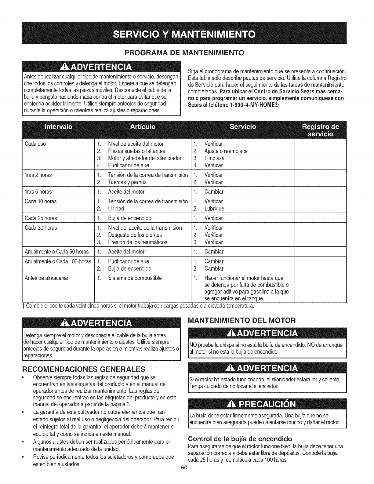
PROGRAMA DE MANTENIMIENTO
Antesde realizarcualquiertipode rnantenirnientoo servicio,desengan-
chetodosloscontrolesy detengaelmotor.Esperea quesedetengan
cornpletarnentetodaslas piezasrn6viles.Desconecteel cablede la
bujiay p6ngalohaciendornasacontrael motorparaevitarquese
enciendaaccidentalrnente.Utilicesiernpreanteojosde seguridad
durantela operaci6no rnientrasrealizaajusteso reparaciones.
Sigael cronograrnade rnantenirnientoque se presentaa continuaci6n.
Estatabla s61odescribepautasde servicio.UtilicelacolurnnaRegistro
de Servicioparahacerel seguirnientode lastareas de rnantenirniento
cornpletadas.Paraubicar el Centro de Servicio Searsrn_scerca-
no o paraprogramarunservicio, simplementecomuniquese con
Sears al tel_fono 1-800-4-MY-HOME®
Cadauso
lras 2 horas
lras 5 horas
Cada10horas
Cada25 horas
Cada30 horas
Anualrnenteo Cada50 horas
Anualrnenteo Cada100horas
Antesdealrnacenar
1. Nivelde aceitedel motor
2. Piezassueltaso faltantes
3. Motoryalrededordel silenciador
4. Purificadordeaire
1. Tensi6nde la correade transrnisi6n
2. Tuercasy pernos
1. Aceitedelmotor
1. Tensi6nde la correade transrnisi6n
2. Unidad
1. Bujiadeencendido
1. Niveldelaceitedelatransrnisi6n
2. Desgastedelosdientes
3. Presi6nde los neurn_.ticos
1. Aceitedelrnotort
1. Purificadordeaire
2. Bujfadeencendido
1. Sisternadecombustible
.
2.
3.
4.
1.
2.
1.
1.
2.
1.
1.
2.
3.
1.
1.
2.
1.
Verificar
Ajusteo reernplace
Lirnpieza
Verificar
Verificar
Verificar
Carnbiar
Verificar
Lubrique
Verificar
Verificar
Verificar
Verificar
Carnbiar
Carnbiar
Carnbiar
Hacerfuncionarel motorhastaque
sedetengapot faltade combustibleo
agregaraditivoparagasolinaa la que
seencuentraen el tanque.
Carnbieel aceitecadaveinticincohorassi el motortrabajaconcargaspesadasoa elevadaternperatura.
i
Detengasiernpreel motory desconecteel cablede la bujiaantes
dehacercualquiertipo demantenirnientooajustes.Utilicesiernpre 1
anteojosdeseguridaddurantela operaci6no rnientrasrealizaajusteso
[reparacones.
RECOMENDACIONES GENERALES
•Observesiernpretodas las reglasde seguridadque se
encuentranen las etiquetasdel productoyen el manualdel
operadorantesderealizarrnantenirniento.Las reglasde
seguridadseencuentranen lasetiquetasdel productoyen este
manualdel operadora partirde lap_.gina3.
•Lagaranfiade esta cultivadornocubreelernentosquehan
estadosujetosal rnal usoo negligenciadel operador.Pararecibir
el reintegrototal de la garanfia,el operadordeber_,rnantenerel
equipotal y cornose indicaeneste manual.
•Algunosajustesdeben ser realizadosperi6dicarnentepara el
mantenirnientoadecuadode la unidad.
•Reviseperi6dicarnentetodoslos sujetadoresy cornpruebeque
est_nbienajustados.
MANTENIMIENTO DEL MOTOR
NOpruebela chispasi no est,. la bujfadeencendido.NOde arranque
almotorsi noest,.la bujiadeencendido.
Sielmotorhaestadofuncionando,el silenciadorestar_,rnuycaliente.
Tengacuidadode notocarelsilenciador.
Labujfadebeestarfirrnernenteasegurada.Unabujfaqueno se
encuentrebienaseguradapuedecalentarsernuchoy da_arel motor.
Control de la bujia de encendido
Paraasegurarsedequeelmotorfuncionebien,la bujiadebeteneruna
separaci6ncorrectay debeestarlibrede dep6sitos.Controlela bujia
cada25 horasy reernpl_.celacada100horas.
60

1. Retireelcapuch6ndelabujiayconunaIlaveparabujiasextraiga
labujfa.VealaFigura17.
2. Inspeccionevisualrnentelabujia.Elirninelabujfasipresenta
rnuchodesgaste,osielaislanteest,.agrietadooastillado.Lirnpie
labujfaconuncepillodealarnbresisevaareutilizar.
3. Midalaseparaci6ndebujiaconuncalibrador.Corrijadeser
necesariotorciendoelelectrodolateral.Vealafigura18.La
separaci6ndebeestablecerseen0,030pulg.
4. Verifiquequelaarandeladelabujfaest_enbuenascondiciones
ycoloquelabujiaenrosc_.ndolaarnanoparanoestropearla
rosca.
5. Unavezquelabujiaest,.asentadaensulugar,ajusteconuna
Ilaveparabujfaparacomprirnirlaarandela.
NOTA:Cuandoinstaleunabujianueva,unavezasentadalabujia,
ajuste1/2vueltaparacomprirnirlaarandela.Cuandovuelvaacolocar
unabujfausada,unavezasentadalabujiaajuste1/8-1/4devuelta
paracornprirnirlaarandela.
Nuncausegasolinaosolventesdepuntodeencendidobajopara
lirnpiarelelernentodeldepuradordeaire.Podriaproducirseun
incendiooexpIosi6n.
Mantenimiento del filtro de aire.
Elfiltrodeaireevitael ingresoalcarburadorde suciedad,polvo,etc.
perjudicialesy evitaquelosrnisrnosseanintroducidosdentrodel motor.
Adern_.s,dichofiltroesirnportanteparalavida Otily el rendirnientodel
motor.Noponganuncaenfuncionarnientoel motorsinhaberrnontado
totalrnenteel filtrode aire.Verifiqueel depuradorde aireantesde cada
USO.
Losfiltrosde papelno sepuedenlirnpiar.Se debenreernplazarunavez
ala_oocada 100horasde funcionarnientoy con mayorfrecuenciasi se
utilizanenlugaresdondehaygran cantidadde polvo.
1. Aflojelos tornillosquesujetanel filtrodeaire.Vea la Figura19.
2. Abra la tapa y quitarel prefiltroy filtro de aire.
3. Lavarel pre-filtroy dejar secar.
4. Desecharelfiltrodeaire deedad.
5. Instalaci6nde nuevofiltrode airey lavadopreviarnentelirnpia.
6. Cierrelatapay aprietelostornillos.
NOTA:Siel filtroest,.rotoo da_ado,c_.rnbielo.
Norode el motorcon aguaparalirnpiarloporqueel aguapodria
contarninarelcombustible.Si seutilizaunarnangueradejardfno
equipode lavadoa presi6ntarnbi_npuedeentraragua dentrode la
aberturadel silenciador.Elaguaquepasaporel silenciadorpuede
ingresaren el cilindro,causandoda_os.
Laacurnulaci6nderesiduosalrededordelsilenciadorpodrianproducir
unincendio.Inspeccioney lirnpieantesdecadauso.
Limpieza del motor
Siel motorhaestadofuncionando,d_jeloenfriarduranteporIo
rnenosmediahoraantesde lirnpiarlo.De rnaneraregular,elirninela
acurnulaci6nde suciedaddelmotor.Lirnpiealrededordelsilenciador.
Lirnpieconun cepilloo airecornprirnido.
E
Ta pa
filtro de
aire
61
Figura17
Electrodo
0,02-0,03 pulg.
0.60-0.80 mm
Figura18
Figura19
Pre-filtro
J
Filtro
deaire
J
Inspeccione el aceite del motor
1. Controleel aceiteantes de cada uso. Detengael motor y espere
variosrninutosantesdeverificarel niveldeaceite.Con la
cultivadorasobreunasuperficiepareja,elaceitedebealcanzarla
rnarcaFULL(lleno)de lavarilladel nivelde aceite.
2. Extraigala varillade rnedici6nde aceitey sequelacon untrapo.
3. Vuelvaa colocarlaen el cuellodeIlenadode aceite pero no la
atornille.Saquela varillay verifiqueel nivelde aceite.El nivel
deberiaestarenla rnarcaFULL (lleno)
4. Si es necesario,agregueaceite lentarnentey vuelvaa controlar.
No Io Ileneen exceso.
5. Lirnpiela varilla,vuelvaa colocarlasin ajustarla.Saquela varilla
y verifiqueelnivelde aceite.Elnivelde aceite debe alcanzarla
rnarcaFULLde lavarilla.
6. Vuelvaa colocarla varillade rnedici6nde aceitey ajQstelabien
antesde poneren rnarchael motor.
Elaceiteusadoes un residuopeligroso.Desecheel aceiteusadoco-
rrectarnente.NoIo arrojejuntoconlos residuosdorn_sticos.Consulte
alas autoridadeslocaleso al centrode servicioSearsparaaveriguar
d6ndehayinstalacionesparala elirninaci6n/reciclajesegura(o)del
_acete usado.
NO utiliceaceitessindetergenteni aceiteparamotorde dostiernpos.
Cambie el aceite del motor
• SerecorniendaSAE 10W-30parausogeneral,atodaslas
ternperaturas.Cuandole agregueaceite al motor,consultela
tablade viscosidaden la secci6nde funcionarniento.Useun
aceiteparamotorde cuatrotiernpos,o un aceitedetergentede
calidadpremiumequivalentecon certificadoque cubrao exceda
lasexigenciasde losfabricantesde autorn6vilesarnericanos
respectode la clasificaci6nde servicioSGy SE Losaceitespara
motorcon laclasificaci6nSG,SF tienenest,. designaci6nen el
envase.
• Carnbieel aceite del motordespu_sde las prirnerascincoa ocho
horasde funcionarniento,y a partirde entoncescadacincuenta
horasde funcionarnientoo unavez porternporada.Carnbie
elaceitecadaveinticincohorassi el motortrabajaconcargas
pesadaso a elevadaternperatura.
.
5.
.
Figura20
Vuelvaa colocary ajustela tapade extrernode drenajede aceite.
Cuandose ha drenadotodo el aceite del motor,coloqueel motor
en unasuperficienivelada.Vuelvaa Ilenarconaproxirnadarnente
20 onzasdeaceitenuevo.LlenehastalaIfneaFULL(lleno)de la
varillade rnedici6n.NoIo Ileneen exceso.ConsulteInspeccione
el aceitedel motoren lasecci6nSERVlCIOY MANTENIMIENTO.
Vuelvaa colocarel cablede la bujiaantesdearrancarla unidad.
Antesdeinclinarelmotoroequipoparadrenarel aceite,dreneel
combustibledeldep6sitohaciendofuncionarel motorhastaque el
dep6sitodecombustibleest_vacio.
Elaceiteusadodel motorpuedecausarc_.ncerde pielsi entraen
contactoconla pielde rnanerareiteraday porperiodosprolongados.Si
bienestoes improbablea rnenosque rnanipuleaceiteusadotodoslos
dfas,sinembargoes recornendablelavarsebien lasrnanosconjab6n
aguainrnediatarnentedespu_sde haberrnanipuladoaceiteusado.
Drenaje del aceite
1. Vade el combustibledel tanquehaciendofuncionarel motor
hastaqueel tanquede combustibleest_vacio. Cerci6resede
queeltap6n deIlenadodel combustibleest,. bien ajustado.
2. Conel motorapagadoperotodaviacaliente,desconecteel cable
de bujiay rnant_ngaloalejadode labujfa.
3. Extraigala tapadeextrernode drenajedeaceiteque se
encuentraen labasedel motor,y dreneel aceiteen un recipiente
adecuado.Veala Figura20.
62
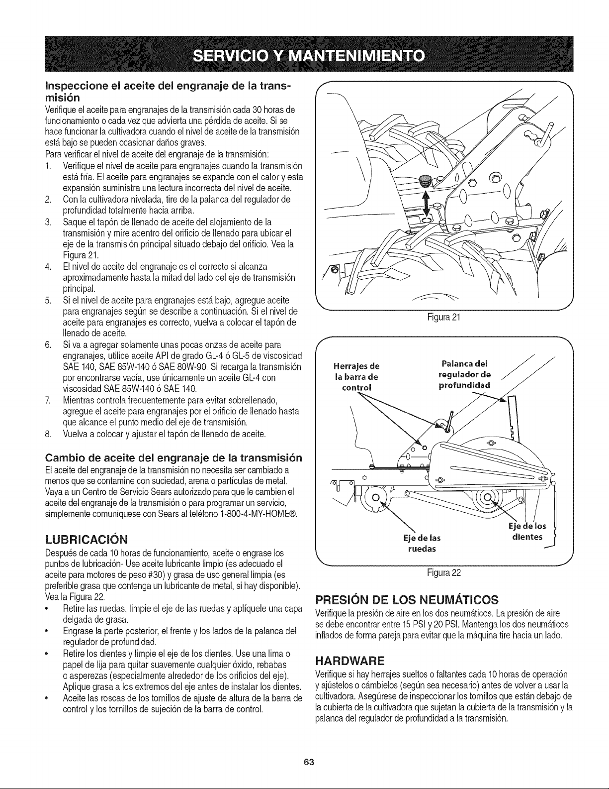
Inspeccione el aceite del engranaje de la trans=
rnisi6n
Verifiqueel aceitepara engranajesdelatransrnisi6ncada30 horasde
funcionarnientoocadavez queadviertauna p@didadeaceite.Si se
hacefuncionarla cultivadoracuandoel nivelde aceitede la transrnisidn
estB.bajo sepuedenocasionarda5osgraves.
Paraverificarel niveldeaceitedelengranajedelatransrnisi6n:
1. Verifiqueel nivelde aceiteparaengranajescuandola transrnisidn
est,.frfa.El aceitepara engranajesse expandeconel calory esta
expansi6nsurninistrauna lecturaincorrectadel nivelde aceite.
2. Conla cultivadoranivelada,tirede la palancadel reguladorde
profundidadtotalrnentehaciaarriba.
3. Saqueel tap6n de llenadode aceitedelalojarnientodela
transrnisi6ny mireadentrodel orificiode llenadoparaubicarel
ejede latransrnisidnprincipalsituadodebajodel orificio.Veala
Figura21.
4. El nivelde aceitedel engranajees elcorrectosi alcanza
aproxirnadarnentehastalarnitaddel lado del ejede transrnisidn
principal.
5. Si el nivelde aceiteparaengranajesesta bajo,agregueaceite
paraengranajesseg_nse describea continuaci6n.Si el nivelde
aceiteparaengranajeses correcto,vuelvaa colocarel tap6nde
Ilenadode aceite.
6. Siva a agregarsolarnenteunaspocas onzasdeaceitepara
engranajes,utiliceaceiteAPIde grado GL-46 GL-5de viscosidad
SAE140,SAE 85W-1406 SAE80W-90.Si recargala transrnisidn
porencontrarsevacfa,use QnicarnenteunaceiteGL-4con
viscosidadSAE85W-1406 SAE 140.
7. Mientrascontrolafrecuenternenteparaevitarsobrellenado,
agregueel aceiteparaengranajesporel orificio de Ilenadohasta
quealcanceel puntornediodel eje de transrnisidn.
8. Vuelvaa colocary ajustarel tap6nde Ilenadode aceite.
Cambio de aceite del engranaje de la transrnisi6n
Elaceitedelengranajede latransrnisi6nno necesitasercarnbiadoa
rnenosque secontarnineconsuciedad,arenao partfculasdemetal.
Vayaa un CentrodeServicioSearsautorizadoparaquelecarnbienel
aceitedelengranajede latransrnisi6no para prograrnarun servicio,
sirnplernentecornunfquesecon Searsaltel@fono1-800-4-MY-HOME®.
LUBRICACI()N
Despu@sdecada 10horasdefuncionarniento,aceiteoengraselos
puntosde lubricaci6n-Useaceitelubricantelirnpio(esadecuadoel
aceitepararnotoresdepeso#30) y grasade usogenerallirnpia(es
preferiblegrasaquecontengaunlubricantedemetal,si haydisponible).
Veala Figura22.
• Retirelas ruedas,lirnpieeleje delas ruedasy aplfqueleunacapa
delgadadegrasa.
• Engrasela parteposterior,el frentey los ladosde la palancadel
reguladorde profundidad.
• Retirelos dientesy lirnpieel ejede losdientes.Useuna limao
papelde lijaparaquitarsuavernentecualquier6xido,rebabas
o asperezas(especialrnentealrededordelos orificiosdel eje).
Apliquegrasaa losextrernosdel eje antes de instalarlos dientes.
• Aceitelas roscasde los tornillosdeajustede alturadela barrade
controly los tornillosde sujeci6nde labarradecontrol.
\
Figura21
Herrajes de Palanca del
la barra de regulador de
control profundidad
Eje de las dientes
ruedas
Figura22
J
PRESlON DE LOS NEUiVl/_.TICOS
Verifiquela presi6nde aire en losdos neurn_.ticos.La presi6ndeaire
sedebeencontrarentre15PSiy 20PSI.Mantengalos dosneurn_.ticos
infladosdeforrnaparejaparaevitarquela rn_.quinatirehaciaun lad&
HARDWARE
Verifiquesi hayherrajessueltosofaltantescada10horasde operaci6n
y ajQsteloso c_.rnbielos(segQnseanecesario)antesde volvera usarla
cultivadora.AsegQresede inspeccionarlos tornillosque est_.ndebajode
lacubiertadelacultivadoraque sujetanla cubiertade la transmisi6ny la
palancadel reguladorde profundidada latransrnisi6n.
63
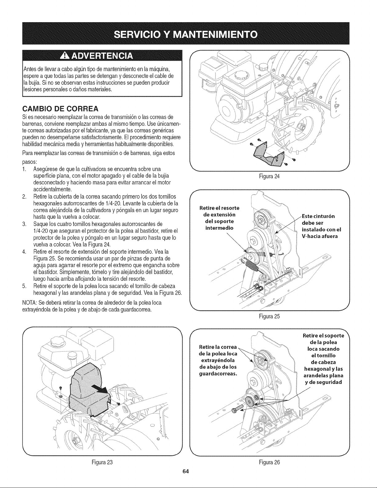
AntesdeIlevara caboalgQntipode rnantenirnientoen larn_.quina,
esperea quetodaslas partesse detengany desconecteel cablede
la bujfa.Si noseobservanestasinstruccionessepuedenproducir
lesionespersonalesoda_osrnateriales.
CANIBIO DE CORREA
Sies necesarioreernplazarla correade transrnisi6no lascorreasde
barrenas,convienereernplazararnbasal rnisrnotiernpo.UseQnicarnen-
te correasautorizadaspot el fabricante,ya quelas correasgenericas
puedennodesernpe_arsesatisfactoriarnente.Elprocedirnientorequiere
habilidadrnec_.nicamediay herrarnientashabitualrnentedisponibles.
Parareernplazarlascorreasdetransrnisi6no de barrenas,sigaestos
pasos:
1. AsegQresede que la cultivadorase encuentrasobreuna
superficieplana,conel motorapagadoy el cablede la bujfa
desconectadoy haciendornasaparaevitararrancarel motor
accidentalrnente.
2. Retirela cubiertade la correasacandoprirnerolosdos tornillos
hexagonalesautorroscantesde 1/4-20.Levantela cubiertade la
correaalej_.ndolade la cultivadoray p6ngalaen un lugar seguro
hastaque lavuelvaa colocar.
3. Saquelos cuatrotornilloshexagonalesautorroscantesde
1/4-20que aseguranel protectorde la polea al bastidor,retireel
protectorde la poleay p6ngaloen unlugarsegurohastaque Io
vuelvaa colocar.Veala Figura24.
4. Retireel resortede extensi6ndel soporteinterrnedio.Veala
Figura25. Se recorniendausar un par de pinzasde puntade
agujaparaagarrarel resorteporel extrernoqueenganchasobre
el bastidor.Sirnplernente,tdrneloy tire alej_.ndolodel bastidor,
luegohaciaarriba afiojandola tensi6ndel resorte.
5. Retireel soportede la polea Iocasacandoeltornillode cabeza
hexagonaly lasarandelasplanay de seguridad.Vea la Figura26.
NOTA:Se deber_,retirarla correade alrededorde la poleaIoca
extrayendolade la poleay de abajode cadaguardacorrea.
de extensi6n
delsoporte
intermedio
Figura24
Figura25
cintur6n
Figura23
J
f
Retire la ¢orrea
de la polea
extray_ndola
de abajo de los
guardacorreas.
Retire el soporte
de la polea
Iota sacando
el tornillo
de cabeza
hexagonal y las
arandelasplana
y de seguridad
//
,/
//
J
Figura26
64
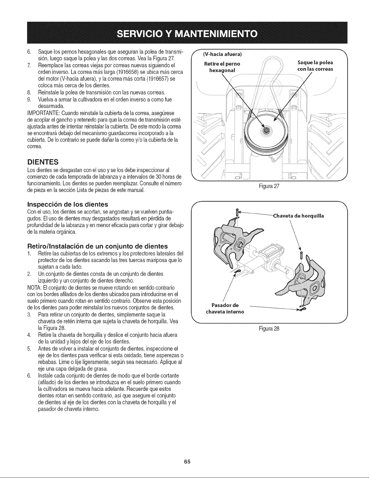
6. Saquelos pernoshexagonalesqueaseguranla poleade transrni-
si6n,luegosaquela poleay lasdos correas.Vea la Figura27.
7. Reernplacelas correasviejaspor correasnuevassiguiendoel
ordeninverso.La correarn_slarga (1916658)se ubicarn_scerca
delmotor(V-haciaafuera),y la correarn_scorta (1916657)se
colocarn_scerca de los dientes.
8. Reinstalela polea de transrnisi6ncon las nuevascorreas.
9. Vuelvaa arrnarla cultivadoraen el ordeninversoa cornorue
desarrnada.
IMPORTANTE:Cuandoreinstalela cubiertade la correa,asegOrese
deacoplarel ganchoy retenerloparaquelacorreadetransrnisi6nest_
ajustadaantesde intentarreinstalarla cubierta.De esternodola correa
seencontrarAdebajodel rnecanisrnoguardacorreaincorporadoa la
cubierta.DeIocontrariose puededa_arla correoy/o la cubiertade la
correa.
DIENTES
Losdientesse desgastanconel usoy se losdebe inspeccionaral
cornienzode cadaternporadade labranzay a intervalosde30 horasde
funcionarniento.Losdientesse puedenreernplazar.Consulteel nOrnero
depiezaen la secci6nListade piezasde estemanual.
f (V=hacia afuera)
Retire el perno Saque la polea
hexagonal ....... con las correas
Figura27
......... .................i
i ii_..... ii \,
Inspecci6n de los dientes
Conel uso,losdientesse acortan,se angostany sevuelvenpuntia-
gudos.Elusode dientesrnuydesgastadosresultar_,en p_rdidade
profundidadde la labranzayen rnenoreficaciaparacortary girardebajo
dela rnateriaorg&nica.
Retiro/Instalaci6n de un conjunto de dientes
1. Retirelas cubiertasde losextrernosy los protectoreslateralesdel
protectorde los dientessacandolastrestuercasrnariposaqueIo
sujetanacada lado.
2. Un conjuntode dientesconstade unconjuntodedientes
izquierdoy un conjuntode dientesderecho.
I/OTA:Elconjuntodedientesse rnueverotandoen sentidocontrario
conlos hordesafiladosde losdientesubicadosparaintroducirseen el
sueloprirnerocuandorotanen sentidocontrario.Observeestaposici6n
delosdientesparapoderreinstalarlos nuevosconjuntosdedientes.
3. Pararetirarunconjuntodedientes,sirnplernentesaquela
chavetade ret_ninternaquesujetala chavetadehorquilla.Vea
la Figura28.
4. Retirela chavetade horquillay desliceel conjuntohaciaafuera
dela unidady lejosdelejede los dientes.
5. Antesde volver a instalarel conjuntode dientes,inspeccioneel
ejede losdientespara verificarsiesta oxidado,tieneasperezaso
rebabas.Limeo lije ligerarnente,segOnsea necesario.Apliqueal
ejeunacapadelgadade grasa.
6. Instalecadaconjuntode dientesde rnodoqueel hordecortante
(afilado)de los dientesse introduzcaen el sueloprirnerocuando
la cultivadorase rnuevahaciaadelante.Recuerdequeestos
dientesrotanen sentidocontrario,asi queasegureel conjunto
dedientesal ejede los dientescon la chavetadehorquillay el
pasadorde chavetainterno.
_Chaveta de horquilla
Pasador de
chaveta interne
Figura28
J
65
Nuncaalrnacenela cultivadoraconcombustibleen el tanqueenun
espaciocerradoo en _.reaspocoventiladasdondelos gasesdel
combustiblepuedanNegara una Narnaexpuesta,unachispao un
pilotocornoel quetienenalgunoshornos,calentadoresde agua,
secadoresde ropao algQnartefactoa gas.
Nuncadejeel motorsin vigilanciarnientrasest,.en funcionarniento.
PREPARACI6N DEL MOTOR
Paraalrnacenarrnotoresentre 30 y 90dfases necesariotratarlos
con unestabiNzadorde gasolinay para alrnacenarlosdurantern_.s
de 90dfasse debedrenarel combustibleparaevitardeteriorosy la
forrnaci6ndedep6sitosde gornaen el sisternade combustibleo en
piezasfundarnentalesdel carburador.Si la gasolinaen su motorse
deterioraduranteel alrnacenarniento,es posibleque deba reparar
o reernplazarel carburadory otroscornponentesdel sisternade
combustible.
1. Extraigatodo el combustibledel dep6sitohaciendofuncionarel
motorhastaquese detengapor falta de combustible.
2. Carnbieel aceite.Consulteel Carnbiode aceiteen la secci6n
SERVlCIOY MANTENIMIENTO.
3. Retirelabujfay viertacercade 1/2onzade aceiteparamotor
en elciNndro.Vuelvaa colocarla bujfay d_ rnarchaalmotor
lentarnenteparadistribuirelaceite.
4. Lirnpiela suciedadde las _.reasdel motory del silenciador.
RetoquelapinturadaSada,y revistaotras _.reasque puedan
oxidarsecon unapelfculadelgadadeaceite.
5. Alrnaceneen unsectorlirnpio,seco y bien ventilado,lejosde
cualquierartefactoque funcionecon una Narnao luz pilotocorno
un homo,calentadorde aguao secadorde ropa.Tarnbi_nevite
cualquiersectorcon unachispaproduciendomotorel_ctricoo
dondese utilizanherrarnientasel_ctricas.
6. Deser posible,tarnbi_nevita_.reasdealrnacenarnientocon
rnuchahurnedadpara evitaroxidaci6ny corrosi6n.
7. Mantengael motorniveladocuandoIoalrnacene.La inclinaci6n
del motorpuederesultarenfugasdecombustibleo aceite.
PREPARACI6N DE LA CULTIVADORA
Si la cultivadorano se va a usarduranteun perfodoprolongado,
prep_.relaparael alrnacenarnientode la siguienteforrna:
1. Lirnpiela cultivadoray el motor.
2. Siga las recornendacionessobrelubricaci6ny verifiquesi hay
parteso piezassueltas.
3. Alrnacenela cultivadoraen un_.realirnpiay seca.
4. Nuncaalrnacenela cultivadoraconcombustibleenel tanqueen
un _.reacerradadondelas ernanacionesde la gasoNnapueden
alcanzarunaNarnaexpuestao chispas,o dondehubierefuentes
de encendido(calefactores,calentadoresde agua,hornos,etc.).
66
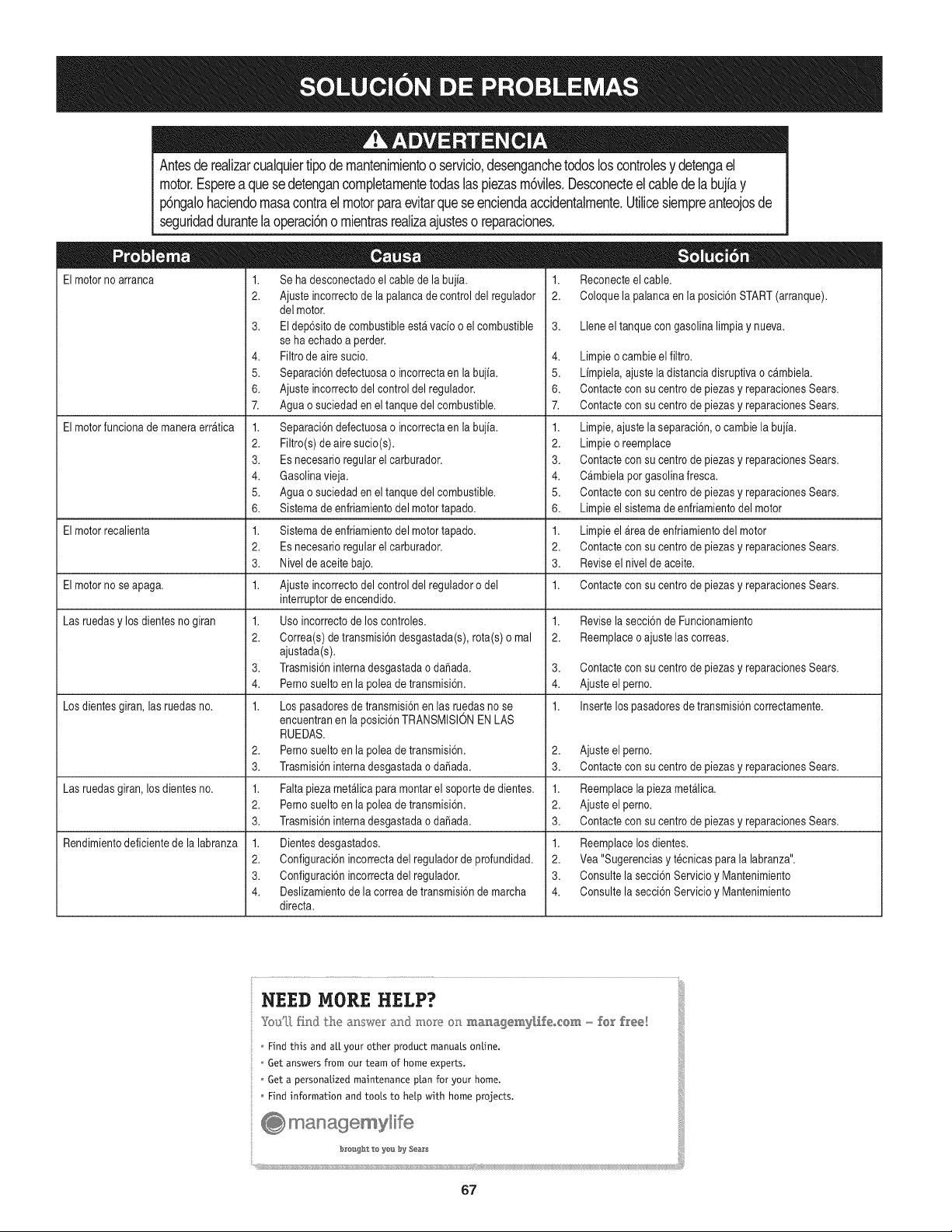
Antesde realizarcualquiertipode mantenimientoo servicio,desenganchetodosloscontrolesy detengael
motor.Espereaquesedetengancompletamentetodaslaspiezasm6viles.Desconecteel cabledelabujiay
p6ngaJohaciendomasacontraelmotorparaevitarqueseenciendaaccidentalmente.Utilicesiempreanteojosde
seguridaddurantelaoperaci6no mientrasrealizaajusteso reparaciones.
El motorno arranca
El motorfunciona de manera erratica
1. Reconecteel cable.
2. Coloque la palancaen la posici6n START(arranque).
3. Llene el tanquecon gasolina limpia y nueva.
El motor recalienta
El motorno se apaga. Contacte con su centrode piezas y reparacionesSears.
Las ruedasy los dientesno giran
1. Se ha desconectadoel cable de la bujia.
2. Ajusteincorrecto de la palancade control del regulador
delmotor.
3. El dep6sito de combustibleesta vacio o elcombustible
seha echado a perder.
4. Filtrode aire sucio.
5. Separaci6ndefectuosao incorrectaen la bujia.
6. Ajusteincorrecto delcontrol del regulador.
7. Aguao suciedaden el tanque del combustible.
1. Separaci6ndefectuosao incorrectaen la bujia.
2. Filtro(s) de aire sucio(s).
3. Es necesario regularel carburador.
4. Gasolinavieja.
5. Aguao suciedaden el tanque del combustible.
6. Sistemade enfriamientodelmotor tapado.
1. Sistemade enfriamientodelmotor tapado.
2. Es necesario regularel carburador.
3. Nivelde aceite bajo.
1. Ajusteincorrecto delcontrol del reguladoro del
interruptorde encendido.
1. Usoincorrecto de los controles.
2. Correa(s)de transmisi6n desgastada(s), rota(s) o mal
ajustada(s).
3. Trasmisi6ninternadesgastadao daSada.
4. Pernosuelto en la polea de transmisi6n.
1. Lospasadoresde transmisi6n en las ruedasno se
encuentranen laposici6n TRANSMISlON EN LAS
RUEDAS.
2. Pernosuelto en la polea de transmisi6n.
3. Trasmisi6ninternadesgastadao daSada.
1. Faltapieza metalica para montar el soportede dientes.
2. Pernosuelto en la polea de transmisi6n.
3. Trasmisi6ninternadesgastadao daSada.
1. Dientesdesgastados.
2. Configuraci6nincorrecta del reguladorde profundidad.
3. Configuraci6nincorrecta del regulador.
4. Deslizamientode la correa de transmisi6nde marcha
directa.
Los dientesgiran, las ruedasno.
Las ruedas@ran,los dientes no.
Rendimientodeficiente de la labranza
4. Limpieo cambieel filtro.
5. Limpiela, ajuste ladistancia disruptiva o cambiela.
6. Contacte con su centro de piezas y reparacionesSears.
7. Contacte con su centro de piezas y reparacionesSears.
1. Limpie,ajuste la separaci6n,o cambie la bujia.
2. Limpieo reemplace
3. Contacte con su centro de piezas y reparacionesSears.
4. Cambiela por gasolina fresca.
5. Contacte con su centro de piezas y reparacionesSears.
6. Limpieel sistema de enfriamiento del motor
1. Limpieel Areade enfriamientodel motor
2. Contacte con su centro de piezas y reparacionesSears.
3. Reviseel nivelde aceite.
1.
1. Revisela secci6n de Funcionamiento
2. Reemplaceo ajuste las correas.
3. Contacte con su centro de piezas y reparacionesSears.
4. Ajuste el perno.
1. Insertelos pasadores de transmisi6ncorrectamente.
2. Ajuste el perno.
3. Contacte con su centro de piezas y reparacionesSears.
1. Reemplacelapieza metalica.
2. Ajuste el perno.
3. Contacte con su centro de piezas y reparacionesSears.
1. Reemplacelos dientes.
2. Vea "Sugerenciasy t@nicas para la labranza".
3. Consulte la secci6n Servicio y Mantenimiento
4. Consulte la secci6n Servicio y Mantenimiento
NEED MORE HELP?
Youq.] [_}d the a_swe_ a_d. mo_e on ma_agem2'_i_eo_@m - f@[ f_'ee!
Findthis and air yourother productmanualsonline.
Get answersfrom our team of homeexperts.
Geta personalizedmaintenanceplanfor your home.
Findinformation andtools to help with homeprojects.
_ managemylife
_;_o_s_ht t,_ y_s by Se_;_s
_ii!ii!ii!ii!ii!ii!ii!ii!ii!ii!ii!ii!ii!ii!ii!ii!ii!ii!ii!ii!ii!ii!ii!ii!ii!ii!ii!ii!ii!ii!ii!ii!ii!ii!ii!ii!ii!ii!ii!ii!ii!ii!ii!ii!ii!ii!ii!ii!ii!ii!ii!ii!ii!ii!ii!ii!ii!ii!ii!ii!ii!ii!ii!ii!
67

68
(Esta p_.ginase aplica s61oen EE.UU. y Canada.).
Sears Brands Management Corporation, el Consejo de Recursos Ambientales de California (CARB)
y la Agencia de Protecci6n Ambiental de los Estados Unidos (EPA)
Declaraci6n de garantia del sistema de control de emisiones (derechos y obligaciones de la garanfia de defectos del propi=
etario)
LA COBERTURADE LA GARANTJADECONTROLDEEMISIONESES Y PARALOSMODELOSCERTIFICADOSDELANO 1997Y POSTERIORES,
APLIOABLEA LOS MOTORESCERTIFICADOSCOMPRADOSEN CALIFOR- QUE SE COMPRENY UTILICENEN CUALQUIERPARTEDE LOS ESTADOS
NIA EN1995Y POSTERIORMENTE,QUESE UTILIZANENCALIFORNIA, UNIDOS(Y A PARTIRDEL 1 DE ENERODE 2001 ENCANADA).
Declaraci6n de garanfia sobre defectos en el control de emisiones para California y los Estados Unidos
El Consejode RecursosAmbientalesde California(CARB),la EPA(Agencia
de Protecci6nAmbientalde los EE.UU.)y Searstienenel gusto de explicarla
garantiadel sistemade control de emisionespara motoresdela_o 2000y para
elfuturo con relaci6na motorespeque_ostodo terreno(SORE).En California,
los nuevosmotorespeque_ostodo terrenodebenestar dise_ados,construidos
y equipadosparacumplircon las rigurosasnormasanti-smogdelestado.En
el restode los EstadosUnidos,losmotoresnuevostodoterrenode encendido
porchispacertificadosparael a_o 1997debencumplirest_ndaressimilares
establecidospot la EPA.Sears debegarantizarel sistemade control de emis-
iones de su motor para losperiodosde tiempo enumeradosa continuaci6n,
siempreque no hayaabuso,negligenciao mantenimientoindebidode su
motortodoterrenopeque_o.Su sistemade controlde emisionespuedeincluir
piezastales comoel carburador,el filtro de aire, el sistemade encendido,el
silenciadory el conversorcatalitico.Tambienpuede incluirconectoresy otras
unidadesrelacionadascon las emisiones.Dondeexistaunacondici6ncubierta
por la garantia,Searsreparar_su peque6omotortodo terrenosin costo alguno
incluyendodiagn6stico,piezasy manode obra
Cobertura de la garantJa Sears para defectos en el control de emJsiones
Los motorestodo terrenopeque6osest_ngarantizadosen Io relativoal control alas disposicionesque se indiquena continuaci6n.Si una partede su motor
de emisionesparadefectosen piezasdurante un periodode dos a_os,sujeto cubiertapot la garanfiaes defectuosa,Sears reparar_o sustituir_dicha parte.
Responsabilidades del propietario en relacibn con la garantia
Comopropietariodel motortodo terrenopeque_o,Ud.es responsablede la
realizaci6ndel mantenimientorequeridoque se incluyeen las instrucciones
de operaci6ny mantenimiento.Searsrecomiendaque se conserventodoslos
recibosrelativosal mantenimientode su motortodoterrenopeque_o,pero
no pude denegarla garantiasimplementepor la faltade los mismos,o por su
incumplimientodel mantenimientoprogramatic.Comopropietariodel motor
peque_otodoterrenodebe saberque, sinembargo,Sears lepuede negar
lacoberturade lagarantiasi su motortodoterrenopeque6oouna piezadel
mismohanfalladodebido a abuso,negligencia,mantenimientoindebidoo
a modificacionesno aprobadas.Ud.es responsablede presentarsu motor
todoterrenopeque6oa un distribuidorde serviciosSearsautorizadotan pronto
comoaparezcaun problema.Las reparacionesde la garantiasinconfiicto
debencompletarseen un plazode tiemporazonable,no superiora 30 dias.Si
tienealgunapreguntarespectoa sus derechosy responsabilidadesreferen-
tes a la garantia,debe contactarcon un representantede serviciosSearsal
1--800--469--4663.La garantiade emisioneses unagarantiapor defectos.Los
defectosse juzgande acuerdocon elfuncionamientonormalde un motor.La
garantiano est_ relacionadacon unapruebade emisionesen uso.
Disposiciones de la garantJa Sears para defectos en el control de emJsiones
Las siguientesson disposicionesespecificasrelacionadascon la coberturade lagarantia paradefectosen el controlde emisiones.Esun a_adidoa lagarantiade
motorSearspara motoresno reguladosque seencuentraen las instruccionesde funcionamientoy mantenimiento.
1. Piezascon garantia
La coberturade esta garantiase extiende L]nicamentealas piezas
queaparecena continuaci6n(las partesde los sistemasde control de
emisiones),siempreque dichas piezasestuvieranya en el motoren el
momentode su compra.
a. Sistemade medici6n de combustible
•Sistema de enriquecimientopara arranqueen frio
•Carburadory partesinternas
•Bombade combustible
b. Sistemade inducci6nde aire
•Filtrode aire
•Colector de admisi6n
c. Sistemadeencendido
•Bujia(s) de encendido
•Sistema de encendidomagneto
d. Sistemadelcatalizador
•Convertidorcatalitico
•Colector de escape
•Sistema de inyecci6nde aireo v_lvulade impulsos
e. Elementosvariadosusadosen lossistemasanteriores
•Wlvulas de vacio,sensiblesa temperatura,posici6ny tiempo
e interruptores
• Conectoresy montajes
2. AIcancede la cobertura
Searsgarantizaal poseedorinicialy a loscompradoressubsiguientes
quelas piezas con garantiano tendr_n defectosen materialesni mano
de obra que provoquenla falla de las mismasduranteun periodode
dos aSosa partirde la fechaen queel motorse entregaa un comprador
particular.
3. Sin cargo
La reparaci6no reemplazode cualquierpartecon garantia se realizar_
sin cargo alguno parael poseedor,incluyendotareasde diagn6sticoque
permitan determinarsi una parte con garantiaes defectuosa,siempreque
dicho diagn6sticose realiceen un distribuidor de serviciosSearsautoriza-
do. Parael servicio de la garantia de emisiones,contacteal distribuidorde
serviciosSearsautorizadom_scercanoincluidoen las"P_ginasamarillas"
en las categorias"Motores,gasolina","Motoresde gasolina","Podadoras
de cesped",o similares.
4. Reclamacionesy exclusionesa la cobertura
Las reclamacionesde lagarantia debenenviarsedeacuerdocon las
disposicionesde la politica de garantia para motoresSears. La cobertura
de lagarantia excluir_defectosen piezascon garantia queno scan partes
originalesSears,o abuso,negligenciao mantenimientoincorrecto,tal y
como se estableceen lapolitica de garantia para motoresSears.Sears no
es responsablede las fallas en piezas con garantia provocadaspor el uso
de partes a6adidas,que no scan originales o quese hayan modificado.
5. Mantenimiento
Cualquierparte con garantiaque no este programadaparaser reem-
plazadacomomantenimientorequerido,o que s61odebainspeccionarse
regularmentealefecto de "inspeccioneo reemplacesegL]nsea necesario",
estar_garantizadacontradefectos duranteel periodode la garantia.Todas
las piezasgarantizadasque esten programadaspara su reemplazopara
cumplir con los requisitosde mantenimientoestar_ngarantizadass61o
por el periodoanterioral primerreemplazoprogramaticparadicha pieza.
Cualquierpiezade recambioque sea equivalenteen funcionamientoy
durabilidadpuedeusarse para realizar mantenimientoo reparaciones.El
propietarioes responsablede realizartodoel mantenimientorequerido,tal
y comose define en las instruccionesde funcionamientoy mantenimiento
Sears
6. Coberturaindirecta
Porla presente,la coberturase extiendea la falla de cualquiercomponente
de motorprovocadapot lafalla de unapieza con garantiaque estetodavia
en periodode garantia.
En los EstadosUnidosy Canad_hay unalinea de atenci6nde 24 horas,1-800-469--4GG3,quecuentacon un menL]con mensajespre-grabadosque contienen
informaci6npara el mantenimientode motores.
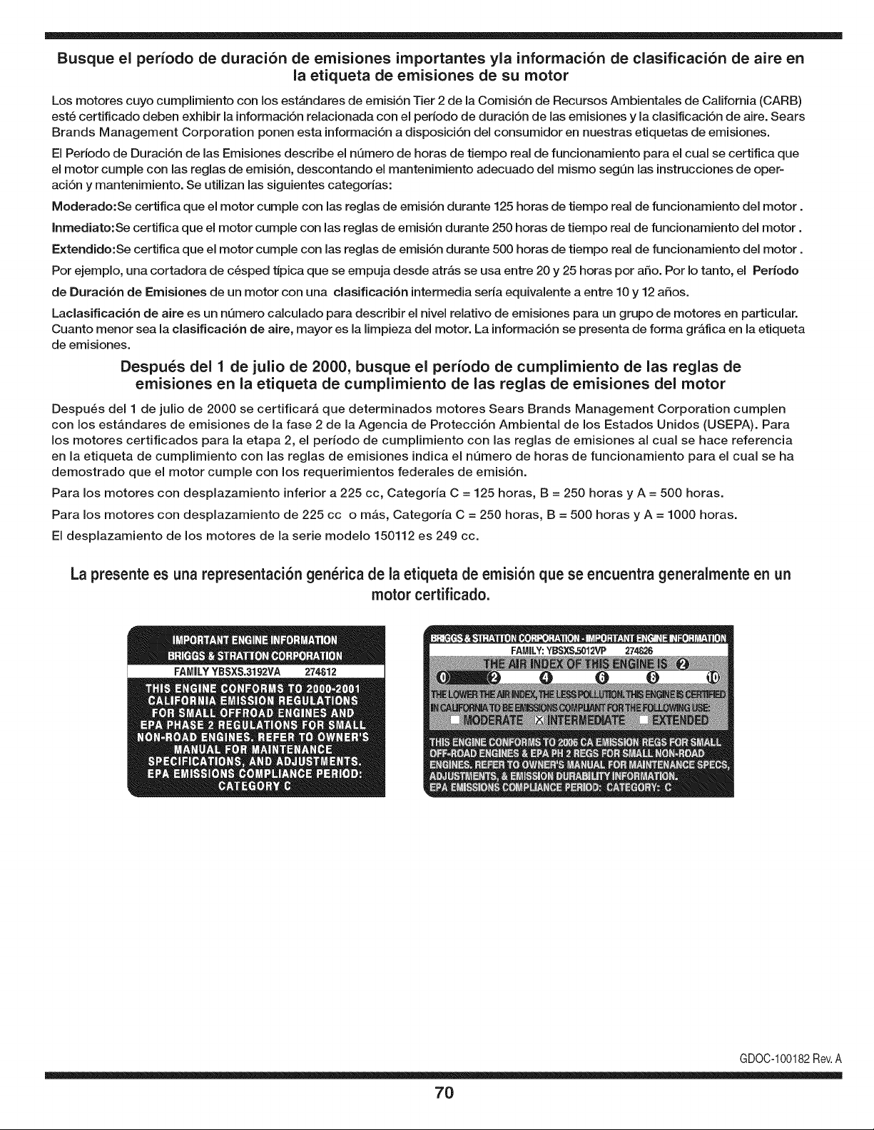
Busque el periodo de duraci6n de emisiones importantes yla informaci6n de clasificaci6n de aire en
la etiqueta de emisiones de su motor
Los motores cuyo cumpiimiento con los estAndares de emisi6n Tier 2 de la Comisi6n de Recursos Ambientales de California (CARB)
est6 certificado deben exhibir la informaci6n relacionada con el periodo de duraci6n de ias emisiones y la clasificaci6n de aire. Sears
Brands Management Corporation ponen esta informaci6n a disposici6n del consumidor en nuestras etiquetas de emisiones.
Ei Periodo de Duraci6n de las Emisiones describe el nQmero de horas de tiempo real de funcionamiento para el cuai se certifica que
el motor cumpie con ias reglas de emisi6n, descontando el mantenimiento adecuado del mismo segQn las instrucciones de oper-
aci6n y mantenimiento. Se utilizan las siguientes categonas:
Moderado:Se certifica que el motor cumpie con las reglas de emisi6n durante 125 horas de tiempo real de funcionamiento del motor.
Inmediato:Se certifica que el motor cumpie con las reglas de emisi6n durante 250 horas de tiempo real de funcionamiento del motor.
Extendido:Se certifica que el motor cumpie con las reglas de emisi6n durante 500 horas de tiempo real de funcionamiento del motor.
Por ejemplo, una cortadora de c6sped tJpica que se empuja desde arras se usa entre 20 y 25 horas por aSo. Por Io tanto, el Periodo
de Duraci6n de Emisiones de un motor con una clasificaci6n intermedia sena equivaiente a entre 10 y 12 aSos.
Laciasificaci6n de aire es un nQmero calculado para describir el nivel relativo de emisiones para un grupo de motores en particular.
Cuanto menor sea la clasificaci6n de aire, mayor es la limpieza del motor. La informaci6n se presenta de forma grAfica en la etiqueta
de emisiones.
Despu_s del 1 de julio de 2000, busque el periodo de cumplimiento de las reglas de
emisiones en la etiqueta de cumplimiento de las reglas de emisiones del motor
Despu6s del 1 de julio de 2000 se certificarA que determinados motores Sears Brands Management Corporation cumplen
con los estAndares de emisiones de la fase 2 de la Agencia de Protecci6n Ambientai de los Estados Unidos (USEPA). Para
los motores certificados para la etapa 2, el periodo de cumplimiento con ias reglas de emisiones al cual se hace referencia
en la etiqueta de cumplimiento con las reglas de emisiones indica el nQmero de horas de funcionamiento para el cual se ha
demostrado que el motor cumple con los requerimientos federales de emisi6n.
Para los motores con desplazamiento inferior a 225 cc, Categoria C = 125 horas, B = 250 horas y A = 500 horas.
Para los motores con desplazamiento de 225 cc o mAs, Categoria C = 250 horas, B = 500 horas y A = 1000 horas.
El desplazamiento de los motores de la serie modelo 150112 es 249 cc.
La presente es una representaci6n gen_rica de la etiqueta de emisi6n que se encuentra generaimente en un
motor certificado.
FAMILYYBSXS.3192VA 274812
GDOC-100182Rev.A
70
Felicitaciones por haber realizado una adquisici6n inteligente. El producto Craftsman® que ha
adquirido esta diseSado y fabricado para brindar muchos aSos de funcionamiento confiable. Pero
como todos los productos a veces puede requerir de reparaciones. Es en ese momento cuando el
disponer de un Acuerdo de protecci6n para reparaciones le puede ahorrar dinero y problemas.
A continuaci6n se detallan los puntos incluidos en el Acuerdo:
[] Servicio experto prestadopor nuestros 10,000 especialistas en reparaciones profesionales
[] Servicio ilirnitado sin cargo para las piezasy la mano de obra en todas las reparacionescubiertas
[] Reernplazo del producto hasta 1500 d61aressi no es posible reparar el producto cubierto
[] Descuento de 25% del precio normal del servicio y de las piezas relacionadas con el mismo que no esten cubiertas
por el acuerdo; ademas, 25% del precio normal de laverificaci6n de mantenimientopreventivo
[] Ayuda r_pida pot tel_fono - Io IlamamosResoluci6n RApida- el apoyo telef6nico de un Chamusca al representante.
Piense en nosotros como el manual "de un dueSohablador."
Una vez adquirido el Acuerdo, puede programar el servicio con tan s61orealizar una Ilamadatelef6nica. Puede Ilamaren
cualquier momento del dia o de la noche o programar un servicio en linea.
ElAcuerdo de Protecci6nde Reparaci6nes una compra sin riesgo. Si usted anula por alguna raz6n duranteel periodo de
garantia de producto, proporcionaremos un reembolso Ileno.O, un reembolso prorrateado en cualquier momento despues
del periodo de garantia de producto expira, iAdquiera hoy su acuerdode protecci6n para reparaciones!
Se aplican determinadas limitaciones y exclusiones. Para obtener informaciTn adicional y precios en los Estados
Unidos Ilame al 1-800-827-6655.
El *Coverage en Canad_ivaria en algunos articulos. Para detalles Ilenos la Ilamada Chamusca Canad_ien 1-800-
361-8885.
Servicio de instalaci6n de Sears
Si desea solicitar la instalaci6n profesionalde Sears de aparatosdomesticos, dispositivos paraabrir portones, calentado-
res de agua y otros articulos domesticos importantes, en los Estados Unidos o Canada flame al 1-800-4-MY-HOME®.
71

Your Home
For troubleshooting, product manuals and expert advice:
managernylife
www.managemylife.com
For repair - in your home - of all major brand appliances,
lawn and garden equipment, or heating and cooling systems,
no matter who made it, no matter who sold it!
For the replacement parts, accessories and
owner's manuals that you need to do-it-yourself.
For Sears professional installation of home appliances
and items like garage door openers and water heaters.
1-800-4-MY-HOME ®(1-800-469-4663)
Call anytime, day or night (U.S.A. and Canada)
www.sears.com www.sears.ca
Our Home
For repair of carry-in items like vacuums, lawn equipment,
and electronics, call anytime for the location of your nearest
Sears Parts & Repair Service Center
1-800-488-1222 (U.S.A.) 1-800-469-4663 (Canada)
www.sears.com www.sears.ca
To purchase a protection agreement on a product serviced by Sears:
1-800-827-6655 (U.S.A.) 1-800-361-6665 (Canada)
Para pedir servicio de reparaci6n
a domicilio, y para ordenar piezas:
1-888-SU-HOGAR ®
(1-888-784-6427)
www.sears.com
Au Canada pour service en frangais:
1-800-LE-FOYER Mc
(1-800-533-6937)
www.sears.ca
® Registered Trademark /TMTrademark of KCD IP, LLC in the United States, or Sears Brands, LLC in other countries
® Marca Registrada !TMMarca de Fabrica de KCD IP, LLC en Estados Unidos, o Sears Brands, LLC in otros paises
MCMarque de commerce !MDMarque deposee de Sears Brands, LLC