Owner's Manual
ICRnFTSMAN°I
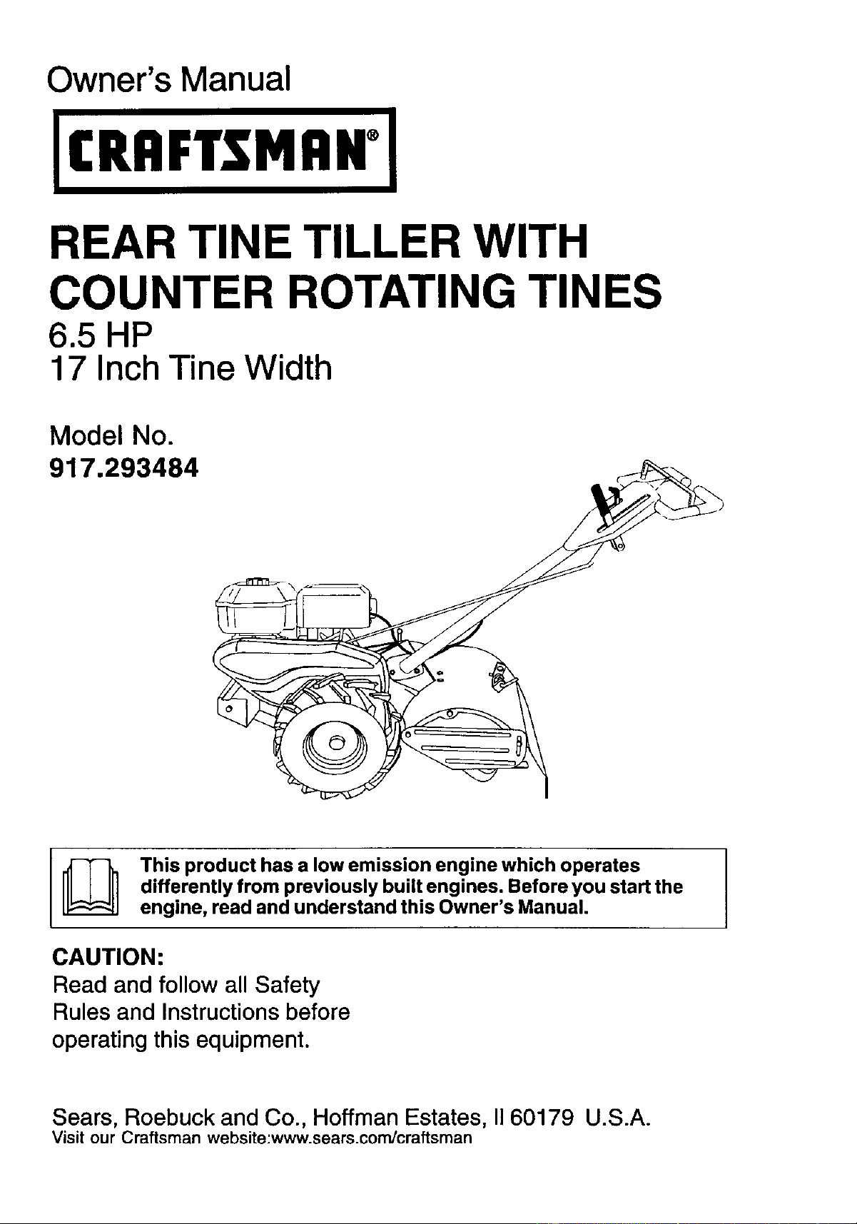
REAR TINE TILLER WITH
COUNTER ROTATING TINES
6.5 HP
17 Inch Tine Width
Model No.
917.293484
This product has a low emission engine which operates
differently from previously built engines. Before you start the
engine, read and understand this Owner's Manual.
CAUTION:
Read and follow all Safety
Rules and Instructions before
operating this equipment.
Sears, Roebuck and Co., Hoffman Estates, II 60179 U.S.A.
Visit our Craftsman website:www.sears.com/craftsman
Safety Rules ......................................... 2
Warranty ............................................... 2
Product Specifications .......................... 4
Assembly .............................................. 5
Operation .............................................. 8
Maintenance ....................................... 13
Service and Adjustments .................... 15
Storage ............................................... 19
Troubleshooting ................................. 20
Illustrated Parts List ............................ 42
Sears Service ...................... Back Cover
LIMITED TWO YEAR WARRANTY ON CRAFTSMAN TILLER
For two (2) years from date of purchase, when this Craftsman Tiller is maintained,
lubricated, and tuned up according to the operating and maintenance instructions in
the owner's manual, Sears will repair free of charge any defect in material or workman-
ship.
This Warranty does not cover:
• Expendable items which become worn during normal use, such as tines, spark
plugs, air cleaners and belts.
• Repairs necessary because of operator abuse or negligence, including bent
crankshafts and the failure to maintain the equipment according to the instructions
contained in the owner's manual..
• If this Craftsman Tiller is used for commercial or rental purposes, this Warranty
applies for only thirty (30) days from the date of purchase.
Warranty service is available by returning the craftsman power mower to the nearest
sears service center/department in the united states. This warranty applies only while
this product is in use in the united states.
This Warranty gives you specific legal rights, and you may also have other rights which
vary from state to state.
SEARS, ROEBUCKAND CO., D/817WA, HOFFMAN ESTATES, IL 60179 U.S.A.
IMPORTANT; This cutting machine is capable of amputating hands and feet and
throwing objects. Failure to observe the following safety instructions could result in
serious injury or death.
TRAINING
• Read the Owner's Manual carefully. Be
thoroughly familiar with the controls
and the proper use of the equipment.
Know how to stop the unit and disen-
gage the controls quickly.
• Never allow children to operate the
equipment. Never allow adults to
operate the equipment without proper
instruction.
• Keep the area of operation clear of all
persons, particularly small children,
and pets.
PREPARATION
• Thoroughly inspect the area where the
equipment is to be used and remove all
foreign objects.
2
• Disengage all clutches and shift into
neutral before starting the engine
(motor).
• Do not operate the equipment without
wearing adequate outer garments.
Wear footwear that will improve footing
on slippery surfaces.
• Handle fuel with care; it is highly
flammable.
• Use an approved fuel container.
• Never add fuel to a running engine or
hot engine.
• Fill fuel tank outdoors with extreme
care. Never fill fuel tank indoors.
• Replace gasoline cap securely and
clean up spilled fuel before restarting.
• Use extension cords and receptacles
as specified by the manufacturer for all
units with electric drive motors or
electric starting motors.
• Never attempt to make any adjustments
while the engine (motor) is running
(except where specifically recommend-
ed by manufacturer).
OPERATION
• Do not put hands or feet near or under
rotating parts.
• Exercise extreme caution when
operating on or crossing gravel drives,
walks, or roads. Stay alert for hidden
hazards or traffic. Do not carry passen-
gers.
• After striking a foreign object, stop the
engine (motor), remove the wire from
the spark plug, thoroughly inspect the
tiller for any damage, and repair the
damage before restarting and operat-
ing the tiller.
• Exercise caution to avoid slipping or
falling.
• If the unit should start to vibrate
abnormally, stop the engine (motor)
and check immediately for the cause.
Vibration is generally a warning of
trouble.
• Stop the engine (motor) when leaving
the operating position.
• Take all possible precautions when
leaving the machine unattended.
Disengage the tines, shift into neutral,
and stop the engine.
• Before cleaning, repairing, or inspect-
ing, shut off the engine and make
certain all moving parts have stopped.
Disconnect the spark plug wire, and
keep the wire away from the plug to
prevent accidental starting. Disconnect
the cord on electric motors.
• Do not run the engine indoors; exhaust
fumes are dangerous.
• Never operate the tiller without proper
guards, plates, or other safety protec-
tive devices in place.
• Keep children and pets away.
• Do not overload the machine capacity
by attempting to till too deep at too fast
a rate.
• Never operate the machine at high
speeds on slippery surfaces. Look
behind and use care when backing.
• Never allow bystanders near the unit.
• Use only attachments and accessories
approved by the manufacturer of the
tiller.
• Never operate the tiller without good
visibility or light.
• Be careful when tilling in hard ground.
The tines may catch in the ground and
propel the tiller forward. If this occurs,
let go of the handlebars and do not
restrain the machine.
MAINTENANCEAND STORAGE
• Keep machine, attachments, and
accessories in safe working condition.
• Check shear pins, engine mounting
bolts, and other bolts at frequent
intervals for proper tightness to be sure
the equipment is in safe working
condition.
• Never store the machine with fuel in the
fuel tank inside a building where
ignition sources are present, such as
hot water and space heaters, clothes
dryers, and the like. Allow the engine to
cool before storing in any enclosure.
• Always refer to the operator's guide
instructions for important details if the
tiller is to be stored for an extended
period.
_Look for this symbol to point out
important safety precautions. It means
CAUTIONIH BECOMEALERT!!! YOUR
SAFETY IS INVOLVED.
ACAUTION: Always disconnect spark
plug wire and place wire where it cannot
contact spark plug in order to prevent
accidental starting when setting up,
transporting, adjusting or making repairs.
_,WARNING: Engine exhaust, some of its
constituents, and certain vehicle compo-
nents contain or emit chemicals known to
the State of California to cause cancer
and birth defects or other reproductive
harm.
3
PRODUCT SPECIRCATIONS
Gasoline 3 Quarts
Capacity: Unleaded
Regular
Oil (API-SF-SJ): SAE 30
(Capacity: 19 oz.) (Above 40°F)
SAE5w-30/10W-30
(Below 40°F)
Spark Plug : Champion
(Gap: .030") RC12YC
CONGRATULATIONS on your purchase
of a Sears 1311er.It has been designed,
engineered and manufactured to give
you the best possible dependability and
performance.
Should you experience any problems you
cannot easily remedy, please contact a
Sears or other qualified Service Center.
We have competent, well-trained techni-
cians and the proper tools to service or
repair this unit.
Please read and retain this manual. The
instructions will enable you to assemble
and maintain your tiller properly. Always
observe the "SAFETY RULES".
Your new tiller has been assembled at the
factory with exception of those parts left
unassembled for shipping purposes. To
ensure safe and proper operation of your
tiller all parts and hardware you as-
semble must be tightened securely. Use
the correct tools as necessary to insure
proper tightness.
CUSTOMER RESPONSIBILITIES
• Read and observe the safety rules.
• Follow a regular schedule in maintain-
ing, caring for and using your tiller.
• Follow the instructions under the
=Customer Responsibilities" and
"Storage" sections of this Owner's
Manual.
J_kWARNING: This unit is equipped with
an internal combustion engine and
should not be used on or near any
unimproved forest-covered, brush-
covered or grass covered land unless the
engine's exhaust system is equipped with
a spark arrester meeting applicable local
or state laws (if any). If a spark arrester is
used, it should be maintained in effective
working order by the operator.
In the state of California the above is
required by law (Section 4442 of the
California Public Resources Code).
Other states may have similar laws.
Federal laws apply on federal lands. A
spark arrester for the muffler is available
through your nearest Sears service
center (See REPAIR PARTS section of
this manual).
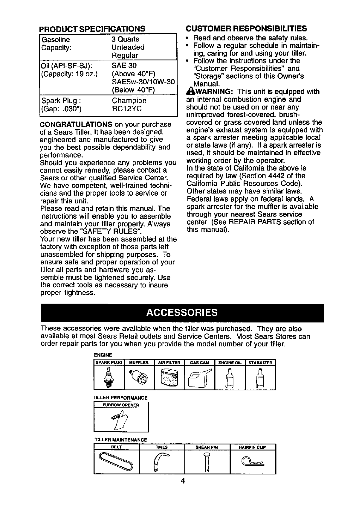
These accessories were available when the tiller was purchased. They are also
available at most Sears Retail outlets and Service Centers. Most Sears Stores can
order repair parts for you when you provide the model number of your tiller.
ENGINE
SPARK___I__PLUGMUFFLER AIR FILTER GAS CAN ENGINE OIL STABILIZER
TILLER PERFORMANCE
FUR_ENER I
TILLER MAINTENANCE
BELT TINES SHEAR PIN HAIRPIN CLIP
4
Your new tiller has been assembled at the
factory with the exception of those parts
left unassembled for shipping purposes.
To ensure safe and proper operation of
your tiller all parts and hardware you
assemble must be tightened securely.
Use the correct tools as necessary to
insure proper tightness.
TOOLS REQUIRED FOR ASSEMBLY
A socket wrench set will make assembly
easier. Standard wrench sizes are listed.
(1) Utility knife
(1) Wire cutter
(1) 13re pressure gauge
(1) Screwdriver
(1) Pair of pliers
(1) 9/16" wrench
OPERATOR'S POSITION
When right or left hand is mentioned in
this manual, it means when you are in the
operating position (standing behind tiller
handles).
LEFT
FRONT
OPERATOR'S
POSITION
RIGHT
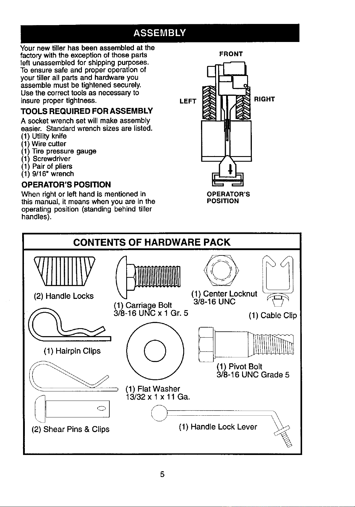
CONTENTS OF HARDWARE PACK
(2) Handle Locks
(1) Hairpin Clips
(2) Shear Pins & Clips
(1) Carriage Bolt
3/8-16 UNC x 1 Gr. 5
(1) Flat Washer
13/32 x 1 x 11 Ga.
©
(1) Center Locknut
3/8-16 UNC
(1) Cable Clip
(1) Pivot Bolt
3/8-16 UNC Grade 5
(1) Handle Lock Lever
5
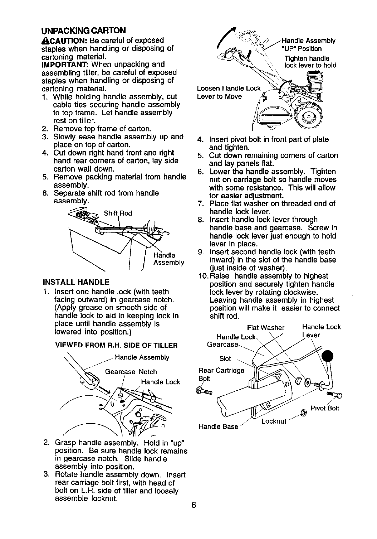
UNPACKING CARTON
_I_CAUTION: Be careful of exposed
staples when handling or disposing of
cartoning material.
IMPORTANT: When unpacking and
assembling tiller, be careful of exposed
staples when handling or disposing of
cartoning material.
1. While holding handle assembly, cut
cable ties securing handle assembly
to top frame. Let handle assembly
rest on tiller.
2. Remove top frame of carton.
3. Slowly ease handle assembly up and
place on top of carton.
4. Cut down right hand front and right
hand rear corners of carton, lay side
carton wall down.
5. Remove packing material from handle
assembly.
6. Separate shift rod from handle
assembly.
Assembly
INSTALL HANDLE
1. Insert one handle lock (with teeth
facing outward) in geamase notch.
(Apply grease on smooth side of
handle lock to aid in keeping lock in
place until handle assembly is
lowered into position.)
VIEWED FROM R.H. SIDE OF TILLER
Ha-Hand'eAssernbly
arcase Notch
ndle Lock
2. Grasp handle assembly. Hold in "up"
position. Be sure handle lock remains
in geamase notch. Slide handle
assembly into position.
3. Rotate handle assembly down. Insert
rear carriage bolt first, with head of
bolt on L.H. side of tiller and loosely
assemble Iocknut.
,_'" :::_-,,._J.,,,:',,'_ Handle Assembly
!' _ i:,.:_::_.,,/ "UP" Position
<_'k'_ _.. Tighten handle
_-_'_.i", lock lever tllpohold
Loosen Handle Lo_
4. Insert pivot bolt in front part of plate
and tighten.
5. Cut down remaining corners of carton
and lay panels flat.
6. Lower the handle assembly. Tighten
nut on carriage bolt so handle moves
with some resistance. This will allow
for easier adjustment.
7. Place flat washer on threaded end of
handle lock lever.
8. Insert handle lock lever through
handle base and gearcase. Screw in
handle lock lever just enough to hold
lever in place.
9. Insert second handle lock (with teeth
inward) in the slot of the handle base
(just inside of washer).
10. Raise handle assembly to highest
position and securely tighten handle
lock lever by rotating clockwise.
Leaving handle assembly in highest
position will make it easier to connect
shift rod.
Flat Washer Handle Lock
Handle Lock Lever
Gearcase_
Slot
Rear Cartridge
Handle Base
Locknut j
J
Pivot Bolt
6
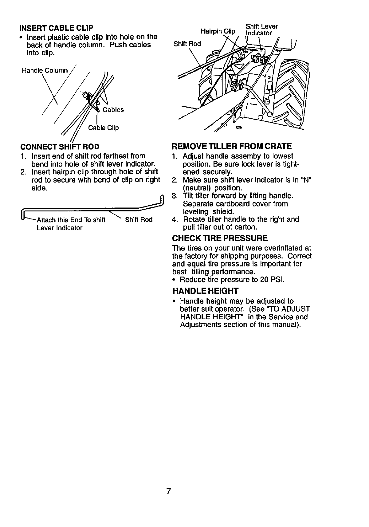
INSERT CABLE CLIP
• Insert plastic cable clip into hole on the
back of handle column. Push cables
into clip.
Handle Column
Hairpir7
Shift Rod
Shift Lever
Indicator
, Cables
Cable Clip
CONNECT SHIFT ROD
1. Insert end of shift rod farthest from
bend into hole of shift lever indicator.
2. Insert hairpin clip through hole of shift
rod to secure with bend of clip on right
side.
LAttach this End To shift _ Shift Rod
Lever Indicator
REMOVE TILLER FROM CRATE
1. Adjust handle assemby to lowest
position. Be sure lock lever is tight-
ened securely.
2. Make sure shift lever indicator is in "N"
(neutral) position.
3. Tilt tiller forward by lifting handle.
Separate cardboard cover from
leveling shield.
4. Rotate tiller handle to the right and
pull tiller out of carton.
CHECKTIREPRESSURE
The tires on your unit were overinfiated at
the factory for shipping purposes. Correct
and equal tire pressure is important for
best tilling performance.
• Reduce tire pressure to 20 PSI.
HANDLE HEIGHT
• Handle height may be adjusted to
better suit operator, (See "TO ADJUST
HANDLE HEIGHT" in the Service and
Adjustments section of this manual).
7
These symbols may appear on your Tiller or in literature supplied with the product.
Learn and understand their meaning.
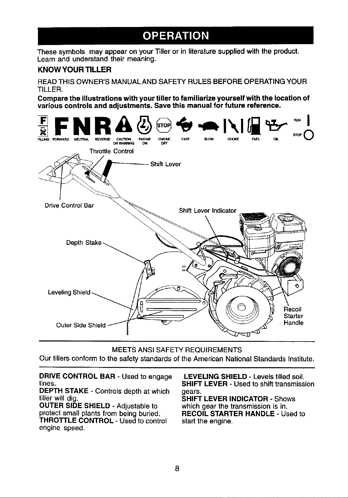
KNOW YOUR TILLER
READ THIS OWNER'S MANUALAND SAFETY RULES BEFORE OPERATING YOUR
TILLER,
Compare the illustrations with your tiller to familiarize yourself with the location of
various controls and adjustments. Save this manual for future reference.
FNR& ®
FILLING FORWARD NEUTRAL REVERSE CALr t'IIGN ENGINE ENGINE FAST SLOW C),XJKE FUEL OIL
OR WARNIt_i ON OFF
Throttle Control
Shift Lever
Drive Control Bar
Shift Lever Indicator
Leveling
c ©
Recoil
Starter
Outer Side Handle
MEETS ANSI SAFETY REQUIREMENTS
Our tillers conform to the safety standards of the American National Standards Institute.
DRIVE CONTROL BAR - Used to engage
tines.
DEPTH STAKE - Controls depth at which
tiller will dig.
OUTER SIDE SHIELD - Adjustable to
protect small plants from being buried.
THROTTLE CONTROL - Used to control
engine speed.
LEVELING SHIELD - Levels tilled soil.
SHIFT LEVER - Used to shift transmission
gears.
SHIFT LEVER INDICATOR - Shows
which gear the transmission is in.
RECOIL STARTER HANDLE - Used to
start the engine.
8
The operation of any tiller can result in foreign objects thrown into the eyes,
which can result in severe eye damage. Always wear safety glasses or eye
shields before starting your tiller and while tilling.We recommend a wide
vision safety mask over spectacles or standard safety glasses.
HOW TO USE YOUR TILLER
Know how to operate all controls before
adding fuel and oil or attempting to start
engine.
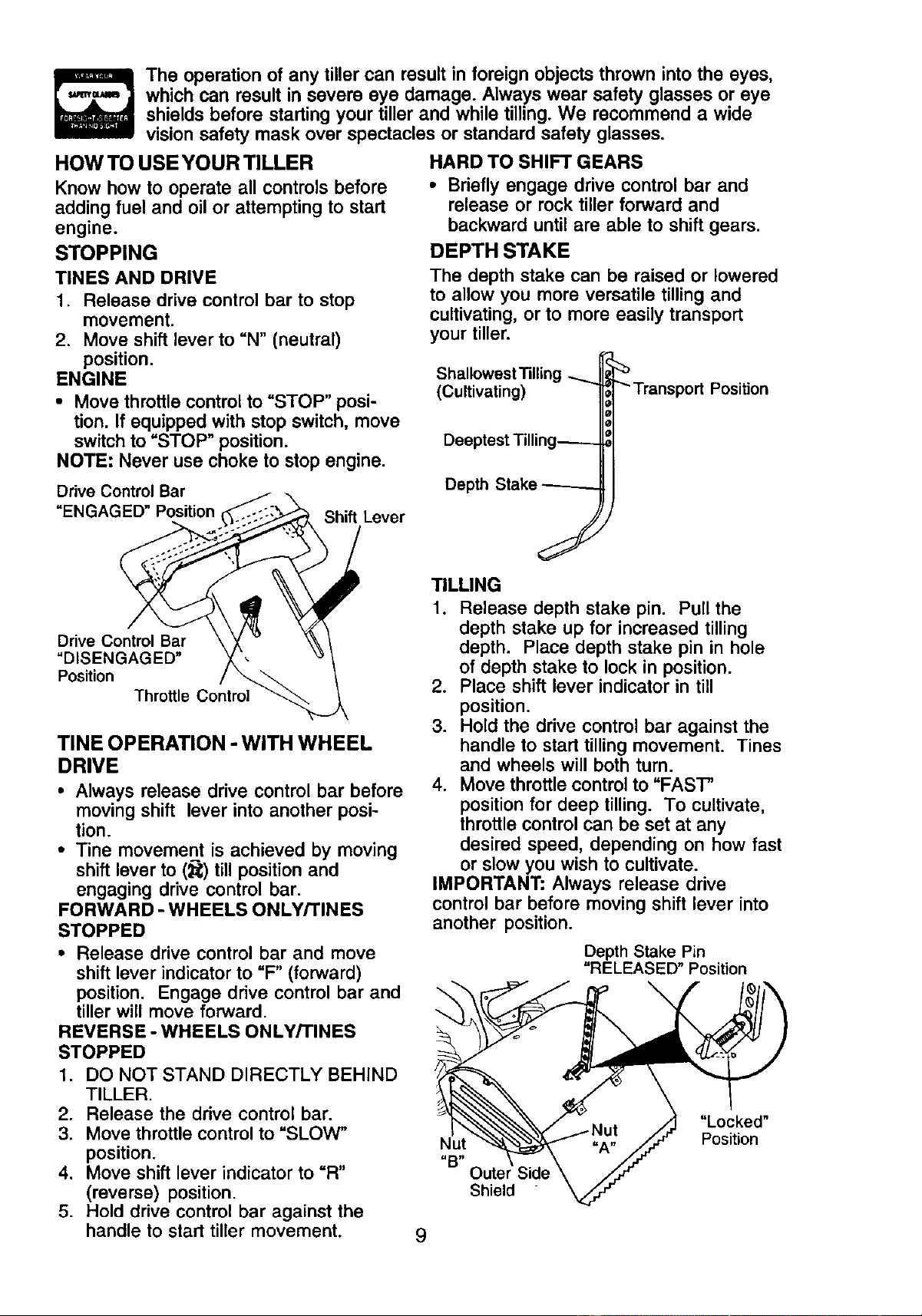
STOPPING
TINES AND DRIVE
1. Release drive control bar to stop
movement.
2. Move shift lever to "N" (neutral)
position.
ENGINE
• Move throttle control to =STOP" posi-
tion. If equipped with stop switch, move
switch to =STOP" position.
NOTE: Never use choke to stop engine.
Drive Control Bar
=ENGAGED" Position
Shift Lever
HARD TO SHIFT GEARS
• Briefly engage drive control bar and
release or rock tiller forward and
backward until are able to shift gears.
DEPTH STAKE
The depth stake can be raised or lowered
to allow you more versatile tilling and
cultivating, or to more easily transport
your tiller.
ShallowestTilling ..........
(Cultivating)
Deeptest Tilling_
Depth Stake ------.
"Transport Position
J
Drive Control Bar
"DISENGAGED"
Position
Throttle Control
TINE OPERATION -WITH WHEEL
DRIVE
• Always release drive control bar before
moving shift lever into another posi-
tion.
• Tine movement is achieved by moving
shift lever to (_) till position and
engaging drive control bar.
FORWARD - WHEELS ONLY/TINES
STOPPED
• Release drive control bar and move
shift lever indicator to =F" (forward)
position. Engage drive control bar and
tiller will move forward.
REVERSE - WHEELS ONLY/TINES
STOPPED
1. DO NOT STAND DIRECTLY BEHIND
TILLER.
2. Release the drive control bar.
3. Move throttle control to "SLOW"
position.
4. Move shift lever indicator to "R"
(reverse) position.
5. Hold drive control bar against the
handle to start tiller movement.
TILLING
1. Release depth stake pin. Pull the
depth stake up for increased tilling
depth. Place depth stake pin in hole
of depth stake to lock in position.
2. Place shift lever indicator in till
position.
3. Hold the drive control bar against the
handle to start tilling movement. Tines
and wheels will both turn.
4. Move throttle control to "FAST"
position for deep tilling. To cultivate,
throttle control can be set at any
desired speed, depending on how fast
or slow you wish to cultivate.
IMPORTANT: Always release drive
control bar before moving shift lever into
another position.
Depth Stake Pin
"RELEASED" Position
\
Nut
=B"
Oute
Shield
"Locked"
Position
9
TURNING
1. Release the drive control bar.
2. Move throttle control to =SLOW"
position.
3. Place shift lever indicator in "F"
(forward) position. Tines will not turn.
4. Lift handle to raise tines out of ground.
5. Swing the handle in the opposite
direction you wish to turn, being
careful to keep feet and legs away
from tines.
6. When you have completed your turn-
around, release the drive control bar
and lower handle. Place shift lever in
(till) position and move throttle control
to desired speed. To begin tilling,
hold drive control bar against the
handle.
OUTER SIDE SHIELDS
The back edges of the outer side shields
are slotted so that the shields can be
raised for deep tilling and lowered for
shallow tilling to protect small plants from
being buried.
1. Loosen nut "A" in slot and nut "B".
2. Move shield to desired position (both
sides).
3. Retighten nuts.
TO TRANSPORT
_I, CAUTION: Before lifting or transporting,
allow tiller engine and muffler to cool.
Disconnect spark plug wire. Drain
gasoline from fuel tank.
AROUND THE YARD
1. Release the depth stake pin. Move
the depth stake down to the top hole
for transporting the tiller. Place depth
stake pin in hole of depth stake to lock
in position. This prevents tines from
scuffing the ground.
2. Place shift lever indicator in "F"
(forward) position for transporting.
3. Hold the drive control bar against the
handle to start tiller movement. Tines
will not turn.
4. Move throttle control to desired speed.
AROUND TOWN
1. Disconnect spark plug wire.
2. Drain fuel tank.
3. Transport in upright position to
prevent oil leakage.
BEFORE STARTING ENGINE
IMPORTANT: Be very careful not to allow
dirt to enter the engine when checking or
adding oil or fuel. Use clean oil and fuel
and store in approved, clean, covered
containers, use clean fill funnels.
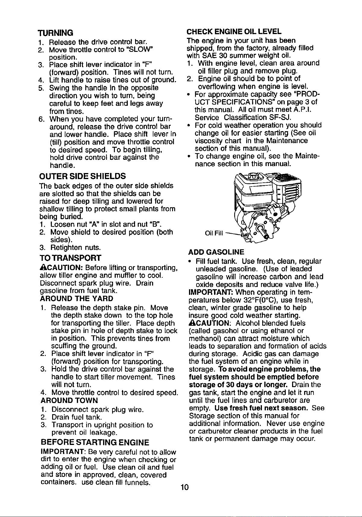
CHECK ENGINE OIL LEVEL
The engine in your unit has been
shipped, from the factory, already filled
with SAE 30 summer weight oil.
1. With engine level, clean area around
oil filler plug and remove plug.
2. Engine oil should be to point of
overflowing when engine is level.
• For approximate capacity see "PROD-
UCT SPECIFICATIONS" on page 3 of
this manual. All oil must meet A.P.I.
Service Classification SF-SJ.
• For cold weather operation you should
change oil for easier starting (See oil
viscosity chart in the Maintenance
section of this manual).
• To change engine oil, see the Mainte-
nance section in this manual.
Oil Fill
ADD GASOLINE
• Fill fuel tank. Use fresh, clean, regular
unleaded gasoline. (Use of leaded
gasoline will increase carbon and lead
oxide deposits and reduce valve life.)
IMPORTANT: When operating in tem-
peratures below 32°F(0°C), use fresh,
clean, winter grade gasoline to help
insure good cold weather starting.
_I_CAUTION: Alcohol blended fuels
(called gasohol or using ethanol or
methanol) can attract moisture which
leads to separation and formation of acids
during storage. Acidic gas can damage
the fuel system of an engine while in
storage. To avoid engine problems, the
fuel system should be emptied before
storage of 30 days or longer. Drain the
gas tank, start the engine and let it run
until the fuel lines and carburetor are
empty. Use fresh fuel next season. See
Storage section of this manual for
additional information. Never use engine
or carburetor cleaner products in the fuel
tank or permanent damage may occur.
10
&CAUTION: Fill to within 1/2 inch of top
of fuel tank to prevent spills and to allow
for fuel expansion. If gasoline is acciden-
tally spilled, move machine away from
area of spill. Avoid creating any source of
ignition until gasoline vapors have
disappeared.
Do not overfill. Wipe off any spilled oil or
fuel. Do not store, spill or use gasoline
near an open flame.
TO START ENGINE
&CAUTION: Keep drive control bar in
"DISENGAGED" position when starting
engine.
When starting engine for the first time or if
engine has run out of fuel, it will take
extra pulls of the recoil starter to move
fuel from the tank to the engine.
1. Make sure spark plug wire is properly
connected.
2. Move shift lever indicator to "N"
(neutral) position.
3. Place throttle control in "FAST"
position.
4. Turn fuel shut-off valve 1/4 turn to
open position.
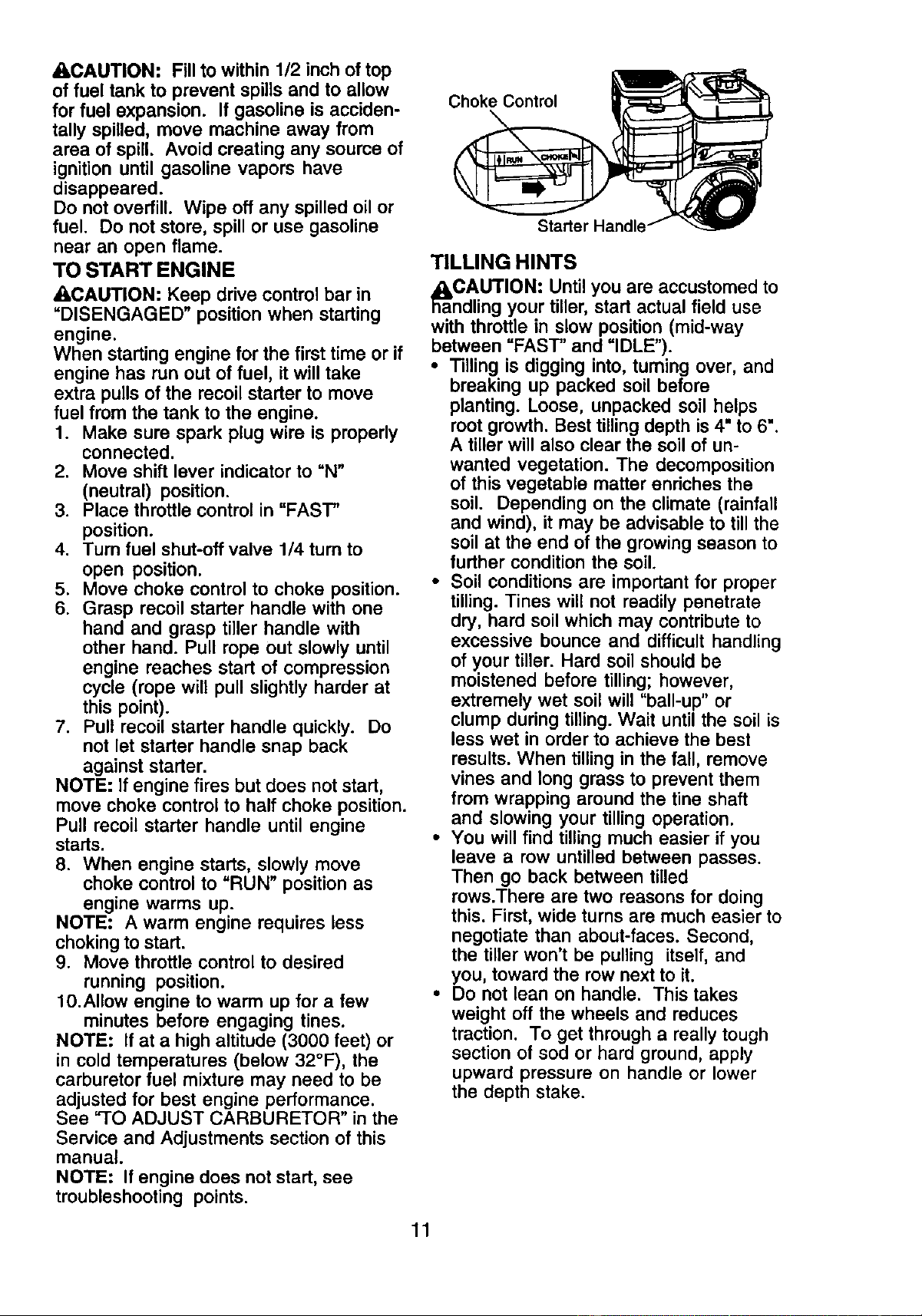
5. Move choke control to choke position.
6. Grasp recoil starter handle with one
hand and grasp tiller handle with
other hand. Pull rope out slowly until
engine reaches start of compression
cycle (rope will pull slightly harder at
this point).
7. Pull recoil starter handle quickly. Do
not let starter handle snap back
against starter.
NOTE: If engine fires but does not start,
move choke control to half choke position.
Pull recoil starter handle until engine
starts.
8. When engine starts, slowly move
choke control to "RUN" position as
engine warms up.
NOTE: A warm engine requires less
choking to start.
9. Move throttle control to desired
running position.
10.Allow engine to warm up for a few
minutes before engaging tines.
NOTE: If at a high altitude (3000 feet) or
in cold temperatures (below 32°F), the
carburetor fuel mixture may need to be
adjusted for best engine performance.
See "TO ADJUST CARBURETOR" in the
Service and Adjustments section of this
manual.
NOTE: If engine does not start, see
troubleshooting points.
Choke Contml
11
TILLING HINTS
_aaCAUTION: Until you are accustomed to
ndling your tiller, start actual field use
with throttle in slow position (mid-way
between "FAST" and "IDLE").
• Tilling is digging into, turning over, and
breaking up packed soil before
planting. Loose, unpacked soil helps
root growth. Best tilling depth is 4" to 6".
A tiller will also clear the soil of un-
wanted vegetation. The decomposition
of this vegetable matter enriches the
soil. Depending on the climate (rainfall
and wind), it may be advisable to till the
soil at the end of the growing season to
further condition the soil.
• Soil conditions are important for proper
tilling. Tines will not readily penetrate
dry, hard soil which may contribute to
excessive bounce and difficult handling
of your tiller. Hard soil should be
moistened before tilling; however,
extremely wet soil will "ball-up" or
clump during tilling. Wait until the soil is
less wet in order to achieve the best
results. When tilling in the fall, remove
vines and long grass to prevent them
from wrapping around the tine shaft
and slowing your tilling operation.
• You will find tilling much easier if you
leave a row untilled between passes.
Then go back between tilled
rews.There are two reasons for doing
this. First, wide turns are much easier to
negotiate than about-faces. Second,
the tiller won't be pulling itself, and
you, toward the row next to it.
• Do not lean on handle. This takes
weight off the wheels and reduces
traction. To get through a really tough
section of sod or hard ground, apply
upward pressure on handle or lower
the depth stake.
CULTIVATING
Cultivating is destroying the weeds
between rows to prevent them from
robbing nourishment and moisture from
the plants. At the same time, breaking up
the upper layer of soil crust will help
retain moisture in the soil. Best digging
depth is 1" to 3" (2.5-7.5 cm). Lower the
outer side shields to protect small plants
from being buried.
• Cultivate up and down the rows at a
speed which will allow tines to uproot
weeds and leave the ground in rough
condition, promoting no further growth
of weeds and grass.
P'_ A
/-'_\ \
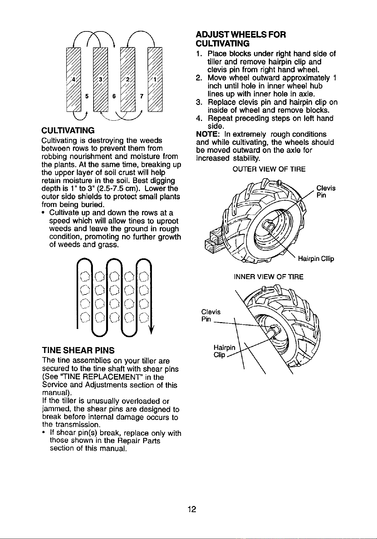
ADJUSTWHEELS FOR
CULTIVATING
1. Place blocks under right hand side of
tiller and remove hairpin clip and
clevis pin from right hand wheel.
2. Move wheel outward approximately 1
inch until hole in inner wheel hub
lines up with inner hole in axle.
3. Replace clevis pin and hairpin clip on
inside of wheel and remove blocks.
4. Repeat preceding steps on left hand
side.
NOTE: In extremely rough conditions
and while cultivating, the wheels should
be moved outward on the axle for
increased stability.
OUTER VIEW OF TIRE
_)__ levis
Pin
Hairpin Cllip
O
Clevis
Pin
INNER VIEW OF TIRE
TINE SHEAR PINS
The tine assemblies on your tiller are
secured to the tine shaft with shear pins
(See "-FINE REPLACEMENT" in the
Service and Adjustments section of this
manual).
If the tiller is unusually overloaded or
jammed, the shear pins are designed to
break before internal damage occurs to
the transmission.
• If shear pin(s) break, replace only with
those shown in the Repair Parts
section of this manual.
Hairpin
12
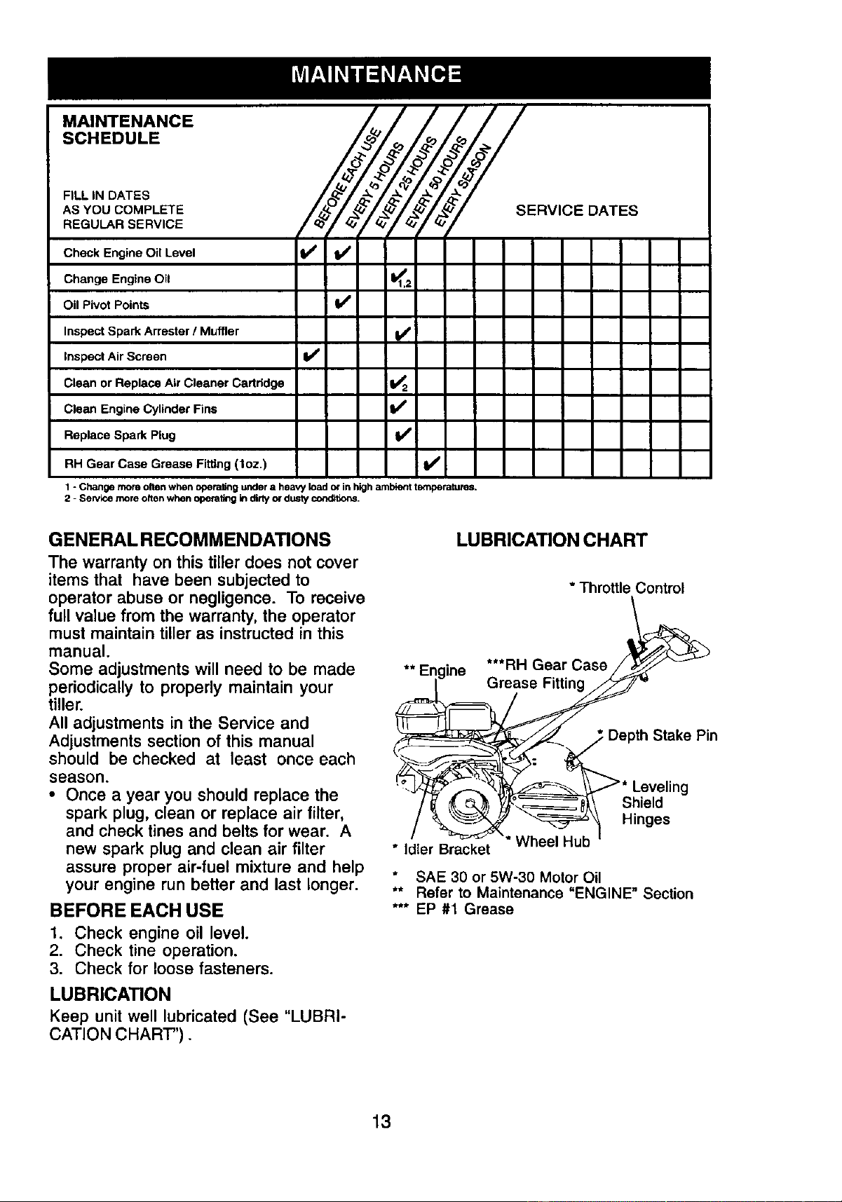
MAINTENANCE
SCHEDULE
FILL IN DATES
AS YOU COMPLETE
REGULAR SERVICE
_
s °v,o
Check Engine Oil Level If If
Change Engine 0il _1
Oil Pivot Points I_
Inspect Spark Arrester / Muffler I_
Inspect Air Screen I1_
Clean or Replace Air Cleaner Cartridge _2
Clean Engine Cylinder Fins t_
Replace Spark Plug V'
RH Gear Case Grease Fiffing (toz.) I_
1 - Change more olten when opera,rig under a heavy load o_"in high arnbie_ temperatures.
2 - Sentice more often when operating in dirtyordusty conditk_,s.
GENERALRECOMMENDATIONS
The warranty on this tiller does not cover
items that have been subjected to
operator abuse or negligence. To receive
full value from the warranty, the operator
must maintain tiller as instructed in this
manual.
Some adjustments will need to be made
periodically to properly maintain your
tiller.
All adjustments in the Service and
Adjustments section of this manual
should be checked at least once each
season.
• Once a year you should replace the
spark plug, clean or replace air filter,
and check tines and belts for wear. A
new spark plug and clean air filter
assure proper air-fuel mixture and help
your engine run better and last longer.
BEFOREEACHUSE
1. Check engine oil level.
2. Check tine operation.
3. Check for loose fasteners.
LUBRICATION
Keep unit well lubricated (See "LUBRI-
CATION CHART").
LUBRICATION CHART
* Throttle Control
** Engine ***RH Gear Cas;e!_-/V
.in es
* Idler Bracket Wheel Hub
SAE 30 or 5W-30 Motor Oil
** Refer to Maintenance "ENGINE" Section
*** EP #1 Grease
13
_IbCAUTION: Disconnect spark plug wire
before performing any maintenance
(except carburetor adjustment) to prevent
accidental starting of engine.
Prevent fires! Keep the engine free of
grass, leaves, spilled oil, or fuel. Remove
fuel from tank before tipping unit for
maintenance. Clean muffler area of all
grass, dirt, and debris.
Do not touch hot muffler or cylinder fins
as contact may cause burns.
ENGINE
LUBRICATION
Use only high quality detergent oil rated
with API service classification SF-SJ.
Select the oil's SAE viscosity grade
according to your expected temperature.
SAEVISCOStTYGRADES
F *20 0 30 3_ 40 60 P_ 100
c ._ ._ -_ _ 1'o _ _
TEMPERATURERANGEANTICIPATEDBEFORENEXTOILCHANGE
NOTE: Although multi-viscosity oils (5W-
30, 10W-30, etc.) improve starting in cold
weather, these multi-viscosity oils will
result in increased oil consumption when
used above 32°F (O°C). Check your
engine oil level more frequently to avoid
possible engine damage from running
low on oil.
Change the oil after every 25 hours of
operation or at least once a year if the
tiller is not used for 25 hours in one year.
Check the crankcase oil level before
starting the engine and after each five (5)
hours of continuous use. Add SAE 30
motor oil or equivalent. Tighten oil filler
plug securely each time you check the oil
level.
TO CHANGE ENGINE OIL
Determine temperature range expected
before oil change. All oil must meet API
service classification SF-SJ.
• Be sure tiller is on level surface.
• Oil will drain more freely when warm.
• Use a funnel to prevent oil spill on tiller,
and catch oil in a suitable container.
1. Remove drain plug.
2. Tip tiller forward to drain oil.
3. After oil has drained completely,
replace oil drain plug and tighten
securely.
4. Remove oil filler plug. Be careful not
to allow dirt to enter the engine.
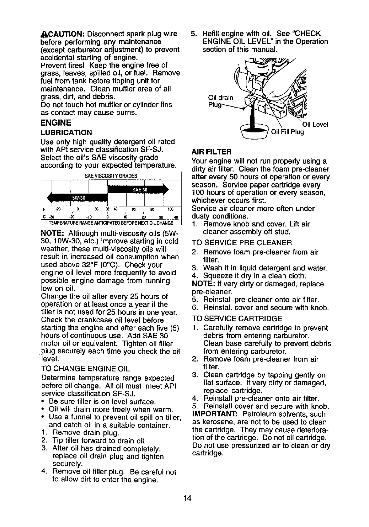
5. Refill engine with oil. See "CHECK
ENGINE OIL LEVEL" in the Operation
section of this manual.
AIR FILTER
Your engine will not run properly using a
dirty air filter. Clean the foam pre-cleaner
after every 50 hours of operation or every
season. Service paper cartridge every
100 hours of operation or every season,
whichever occurs first.
Service air cleaner more often under
dusty conditions.
1. Remove knob and cover. Lift air
cleaner assembly off stud.
TO SERVICE PRE-CLEANER
2. Remove foam pre-cleaner from air
filter.
3. Wash it in liquid detergent and water.
4. Squeeze it dry in a clean cloth.
NOTE: If very dirty or damaged, replace
pre-cleaner.
5. Reinstall pre-cleaner onto air filter.
6. Reinstall cover and secure with knob.
TO SERVICE CARTRIDGE
1. Carefully remove cartridge to prevent
debris from entering carburetor.
Clean base carefully to prevent debris
from entering carburetor.
2. Remove foam pre-cleaner from air
filter.
3. Clean cartridge by tapping gently on
flat surface. If very dirty or damaged,
replace cartridge.
4. Reinstall pre-cleaner onto air filter.
5. Reinstall cover and secure with knob.
IMPORTANT: Petroleum solvents, such
as kerosene, are not to be used to clean
the cartridge. They may cause deteriora-
tion of the cartridge. Do not oil cartridge.
Do not use pressurized air to clean or dry
cartridge.
14
_Cover Knob
Priiiii_ Cartridge
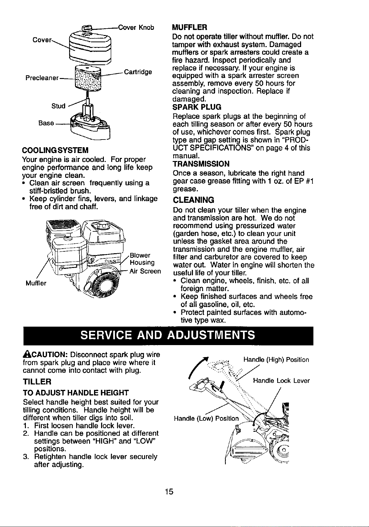
COOLING SYSTEM
Your engine is air cooled. For proper
engine performance and long life keep
your engine clean.
• Clean air screen frequently using a
stiff-bristled brush.
• Keep cylinder fins, levers, and linkage
free of dirt and chaff.
Muffler
Blower
Screen
MUFFLER
Do not operate tiller without muffler. Do not
tamper with exhaust system. Damaged
mufflers or spark arresters could create a
fire hazard. Inspect periodically and
replace if necessary. If your engine is
equipped with a spark arrester screen
assembly, remove every 50 hours for
cleaning and inspection. Replace if
damaged.
SPARK PLUG
Replace spark plugs at the beginning of
each tilling season or after every 50 hours
of use, whichever comes first. Spark plug
type and gap setting is shown in "PROD-
UCT SPECIFICATIONS" on page 4 of this
manual.
TRANSMISSION
Once a season, lubricate the right hand
gear case grease fitting with 1 oz. of EP #1
grease.
CLEANING
Do not clean your tiller when the engine
and transmission are hot. We do not
recommend using pressurized water
(garden hose, etc.) to clean your unit
unless the gasket area around the
transmission and the engine muffler, air
filter and carburetor are covered to keep
water out. Water in engine will shorten the
useful life of your tiller.
• Clean engine, wheels, finish, etc. of all
foreign matter.
• Keep finished surfaces and wheels free
of all gasoline, oil, etc.
• Protect painted surfaces with automo-
tive type wax.
,_,CAUTION: Disconnect spark plug wire
from spark plug and place wire where it
cannot come into contact with plug.
TILLER
TO ADJUST HANDLE HEIGHT
Select handle height best suited for your
tilling conditions. Handle height will be
different when tiller digs into soil.
1. First loosen handle lock lever.
2. Handle can be positioned at different
settings between "HIGH" and =LOW"
positions.
3. Retighten handle lock lever securely
after adjusting.
Handle (Low)
Handle (High) Position
Handle Lock Lever
15
TIRE CARE
_I, CAUTION: When mounting tires, unless
beads are seated, overinflation can
cause an explosion.
• Maintain 20 pounds of tire pressure. If
tire pressures are not equal, tiller will
pull to one side.
• Keep tires free of gasoline or oil which
can damage rubber.
TO REMOVE WHEEL
1. Place blocks under transmission to
keep tiller from tipping.
2, Remove hairpin clip and clevis pin
from wheel.
3. Remove wheel and tire.
4. Repair tire and reassemble.
l Clevis Pin
Hairpin Clip
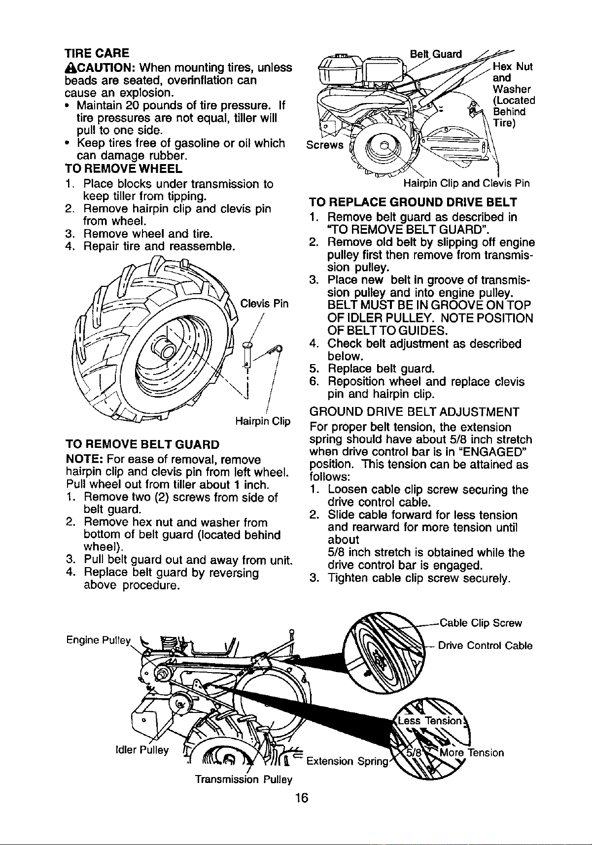
TO REMOVE BELT GUARD
NOTE: For ease of removal, remove
hairpin clip and clevis pin from left wheel.
Pull wheel out from tiller about 1 inch.
1. Remove two (2) screws from side of
belt guard.
2. Remove hex nut and washer from
bottom of belt guard (located behind
wheel).
3. Pull belt guard out and away from unit.
4. Replace belt guard by reversing
above procedure.
Screws
Belt Guard
Hex Nut
Washer
(Located
Behind
Tire)
Hairpin Clip and Clevis Pin
TO REPLACE GROUND DRIVE BELT
1. Remove belt guard as described in
"TO REMOVE BELT GUARD".
2. Remove old belt by slipping off engine
pulley first then remove from transmis-
sion pulley.
3. Place new belt in groove of transmis-
sion pulley and into engine pulley.
BELT MUST BE IN GROOVE ON TOP
OF IDLER PULLEY. NOTE POSITION
OF BELT TO GUIDES.
4. Check belt adjustment as described
below.
5. Replace belt guard.
6. Reposition wheel and replace clevis
pin and hairpin clip.
GROUND DRIVE BELT ADJUSTMENT
For proper belt tension, the extension
spring should have about 5/8 inch stretch
when drive control bar is in "ENGAGED"
position. This tension can be attained as
follows:
1. Loosen cable clip screw securing the
drive control cable.
2. Slide cable forward for less tension
and rearward for more tension until
about
5/8 inch stretch is obtained while the
drive control bar is engaged.
3. Tighten cable clip screw securely.
Engine Pulley\
Clip Screw
Cable
Idler Pulley
Extension Spring
Transmission Pulley
16
More Tension
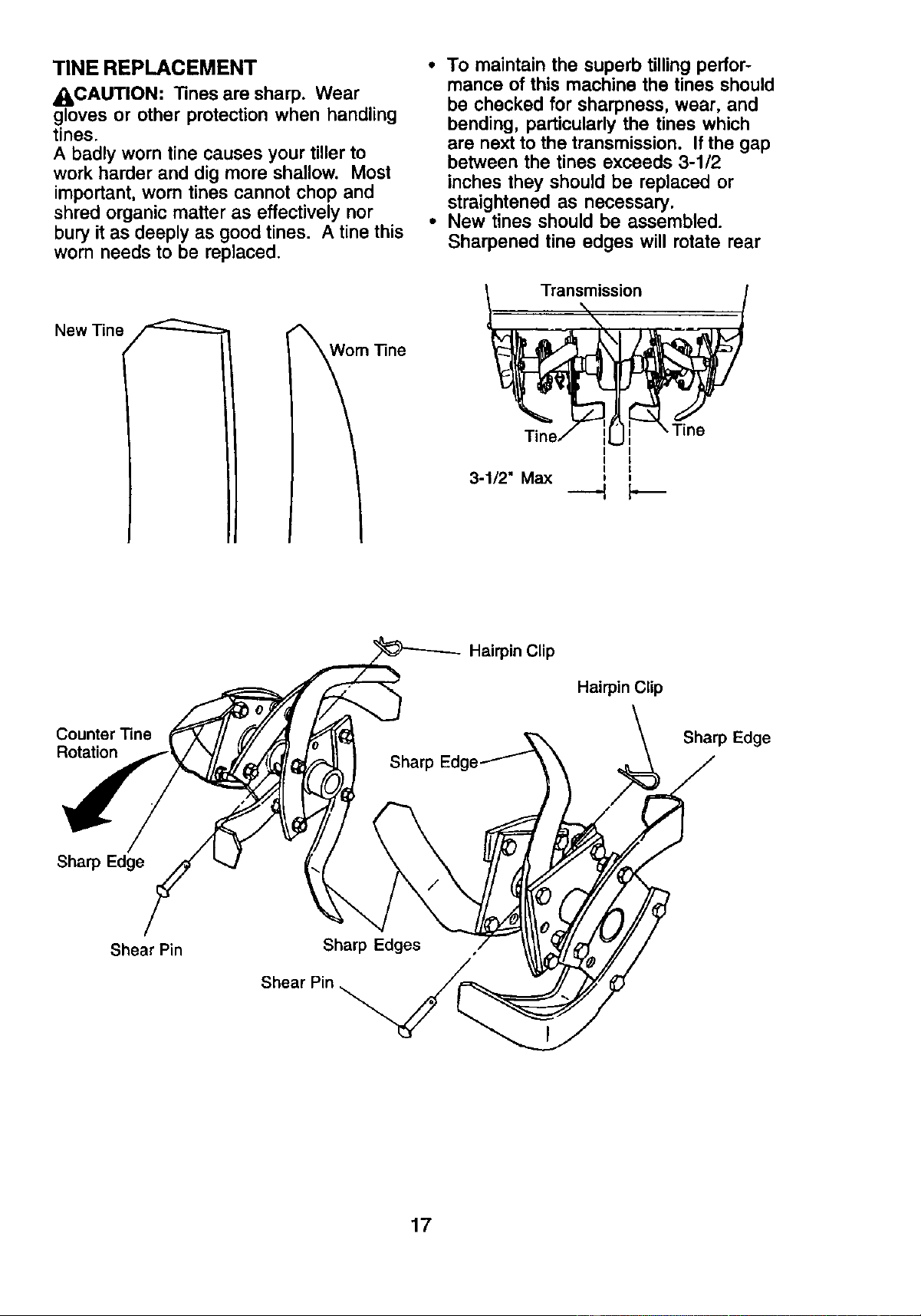
TINE REPLACEMENT
_I_CAUTION: Tines are sharp. Wear
gloves or other protection when handling
tines.
A badly worn tine causes your tiller to
work harder and dig more shallow. Most
important, worn tines cannot chop and
shred organic matter as effectively nor
bury it as deeply as good tines. A tine this
worn needs to be replaced.
New "line
m "Fine
• To maintain the superb tilling perfor-
mance of this machine the tines should
be checked for sharpness, wear, and
bending, particularly the tines which
are next to the transmission. If the gap
between the tines exceeds 3-1/2
inches they should be replaced or
straightened as necessary.
• New tines should be assembled.
Sharpened tine edges will rotate rear
Transmission
I I
I I
3-1/2" Max i ,
---t
Hairpin Clip
Hairpin Clip
Counter "line
Rotation
Sharp Edge
Sharp Edge
Shear Pin
Sharp Edges
Shear
17
ENGINE
Maintenance, repair, or replacement of
the emission control devices and sys-
tems, which are being done at the
customers expense, may be performed
by any non-road engine repair establish-
ment or individual. Warranty repairs must
be performed by an authorized engine
manufacturer's service outlet.
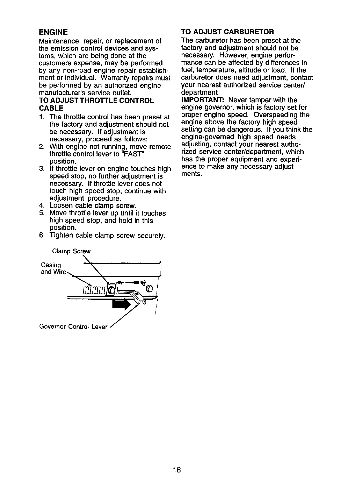
TO ADJUST THRO'rFLE CONTROL
CABLE
1. The throttle control has been preset at
the factory and adjustment should not
be necessary, if adjustment is
necessary, proceed as follows:
2. With engine not running, move remote
throttle control lever to "FAST
position.
3. If throttle lever on engine touches high
speed stop, no further adjustment is
necessary. If throttle lever does not
touch high speed stop, continue with
adjustment procedure.
4. Loosen cable clamp screw.
5. Move throttle lever up until it touches
high speed stop, and hold in this
position.
6. Tighten cable clamp screw securely.
Clamp Screw
\
Casing
and Wire,,.,, "X_
" m
Governor Control Lever _
TO ADJUST CARBURETOR
The carburetor has been preset at the
factory and adjustment should not be
necessary. However, engine perfor-
mance can be affected by differences in
fuel, temperature, altitude or load. If the
carburetor does need adjustment, contact
your nearest authorized service center/
department
IMPORTANT: Never tamper with the
engine governor, which is factory set for
proper engine speed. Overspeeding the
engine above the factory high speed
setting can be dangerous. If you think the
engine-governed high speed needs
adjusting, contact your nearest autho-
rized service center/department, which
has the proper equipment and experi-
ence to make any necessary adjust-
ments.
18
Immediately prepare your tiller for storage
at the end of the season or if the unit will
not be used for 30 days or more.
ACAUTION: Never store the tiller with
gasoline in the tank inside a building
where fumes may reach an open flame or
spark. Allow the engine to cool before
storing in any enclosure.
TILLER
1. Clean entire tiller (See "CLEANING" in
the Maintenance section of this
manual).
2. Inspect and replace belts, if necessary
(See belt replacement instructions in
the Service and Adjustments section
of this manual).
3. Lubricate as shown in the Mainte-
nance section of this manual.
4. Be sure that all nuts, bolts and screws
are securely fastened. Inspect moving
parts for damage, breakage and wear.
Replace if necessary.
5. Touch up all rusted or chipped paint
surfaces; sand lightly before painting.
ENGINE
FUEL SYSTEM
IMPORTANT: It is important to prevent
gum deposits from forming in essential
fuel system parts such as the carburetor,
fuel filter, fuel hose, or tank during
storage. Also, alcohol blended fuels
(called gasohol or using ethanol or
methanol) can attract moisture which
leads to separation and formation of
acids during storage. Acidic gas can
damage the fuel system of an engine
while in storage.
1. Drain the fuel tank.
2. Start the engine and let it run until the
fuel lines and carburetor are empty.
• Never use engine or carburetor cleaner
products in the fuel tank or permanent
damage may occur.
• Use fresh fuel next season.
NOTE: Fuel stabilizer is an acceptable
alternative in minimizing the formation of
fuel gum deposits during storage. Add
stabilizer to gasoline in fuel tank or
storage container. Always follow the mix
ratio found on stabilizer container. Run
engine at least 10 minutes after adding
stabilizer to allow the stabilizer to reach
the carburetor. Do not drain the gas tank
and carburetor if using fuel stabilizer.
ENGINE OIL
Drain oil (with engine warm) and replace
with clean oil (See "ENGINE" in the
Maintenance section of this manual).
CYLINDER
1. Remove spark plug.
2. Pour 1 ounce (29 ml) of oil through
spark plug hole into cylinder.
3. Pull starter handle slowly several
times to distribute oil.
4. Replace with new spark plug.
OTHER
• Do not store gasoline from one season
to another.
• Replace your gasoline can if your can
starts to rust. Rust and/or dirt in your
gasoline will cause problems.
• If possible, store your unit indoors and
cover it to give protection from dust and
dirt.
• Cover your unit with a suitable protec-
tive cover that does not retain moisture.
Do not use plastic. Plastic cannot
breathe which allows condensation to
form and will cause your unit to rust.
IMPORTANT: Never cover tiller while
engine and exhaust areas are still warm.
19
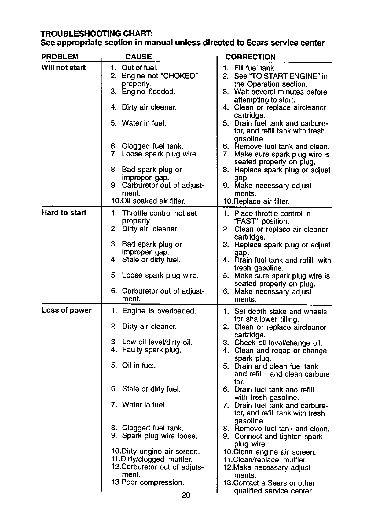
TROUBLESHOOTING CHART:
See appropriate section in manual unless directed to Sears service center
PROBLEM CAUSE
Will not start
Hard to start
Loss of power
1. Out of fuel.
2. Engine not "CHOKED"
properly.
3. Engine flooded.
4. Dirty air cleaner.
5. Water in fuel.
6. Clogged fuel tank.
7. Loose spark plug wire.
8. Bad spark plug or
improper gap.
9. Carburetor out of adjust-
ment.
10.Oil soaked air filter.
1. Throttle control not set
properly.
2. Dirty air cleaner.
3. Bad spark plug or
improper gap.
4. Stale or dirty fuel.
5. Loose spark plug wire.
6. Carburetor out of adjust-
ment.
1. Engine is overloaded.
2. Dirty air cleaner.
3. Low oil level/dirty oil.
4. Faulty spark plug.
5. Oil in fuel.
6. Stale or dirty fuel.
7. Water in fuel.
8. Clogged fuel tank.
9. Spark plug wire loose.
10.Dirty engine air screen.
11.Dirty/clogged muffler.
12.Carburetor out of adjuts-
ment.
13.Poor compression.
20
CORRECTION
1. Fill fuel tank.
2. See "TO START ENGINE" in
the Operation section.
3. Wait several minutes before
attempting to start.
4. Clean or replace aircleaner
cartridge.
5. Drain fuel tank and carbure-
tor, and refill tank with fresh
gasoline.
6. Remove fuel tank and clean.
7. Make sure spark plug wire is
seated properly on plug,
8. Replace spark plug or adjust
gap.
9. Make necessary adjust
ments.
10.Replace air filter.
1. Place throttle control in
"FAST" position.
2. Clean or replace air cleaner
cartridge.
3. Replace spark plug or adjust
gap.
4. Drain fuel tank and refill with
fresh gasoline.
5. Make sure spark plug wire is
seated properly on plug.
6. Make necessary adjust
ments.
1. Set depth stake and wheels
for shallower tilling.
2. Clean or replace aircleaner
cartridge.
3. Check oil level/change oil.
4. Clean and regap or change
spark plug.
5. Drain and clean fuel tank
and refill, and clean carbure
tor.
6. Drain fuel tank and refill
with fresh gasoline.
7. Drain fuel tank and carbure-
tor, and refill tank with fresh
gasoline.
8. Remove fuel tank and clean.
9. Connect and tighten spark
plug wire.
10.Clean engine air screen.
11.Clean/replace muffler.
12.Make necessary adjust-
ments.
13.Contact a Sears or other
qualified service center.
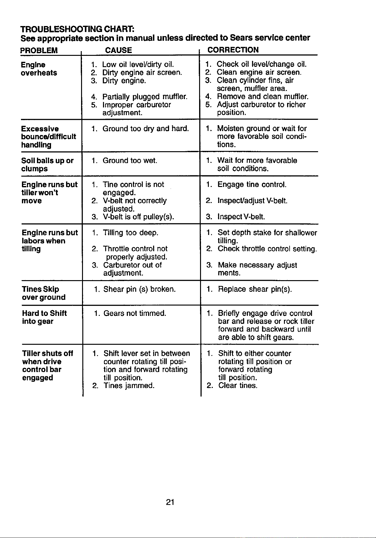
TROUBLESHOOTING CHART:
See appropriate section in manual unless directed to Sears service center
PROBLEM CAUSE CORRECTION
Engine
overheats
1. Low oil level/dirty oil.
2. Dirty engine air screen.
3. Dirty engine.
.
2.
3.
Check oil level/change oil.
Clean engine air screen.
Clean cylinder fins, air
screen, muffler area.
Remove and clean muffler.
Adjust carburetor to richer
position.
4. Partially plugged muffler. 4.
5. Improper carburetor 5.
adjustment.
Excessive 1. Ground too dry and hard. 1. Moisten ground or wait for
bounce/difficult more favorable soil condi-
handling tions.
Soil balls up or 1. Ground too wet. 1. Wait for more favorable
clumps soil conditions.
Engine runs but 1. Tine control is not 1. Engage tine control.
tiller won't engaged.
move 2. V-belt not correctly 2. Inspect]adjust V-belt.
adjusted.
3. V-belt is off pulley(s). 3. InspectV-belt.
Engine runs but 1. Tilling too deep. 1. Set depth stake for shallower
labors when tilling.
tilling 2. Throttle control not 2. Check throttle control setting.
properly adjusted.
3. Carburetor out of 3. Make necessary adjust
adjustment, ments.
TinesSkip 1. Shear pin (s) broken. 1. Replace shear pin(s).
over ground
Hard to Shift 1. Gears not timmed. 1. Briefly engage drive control
into gear bar and release or rock tiller
forward and backward until
are able to shift gears.
1.Tiller shuts off
when drive
control bar
engaged
.
1. Shift lever set in between
counter rotating till posi-
tion and forward rotating
till position.
2. Tines jammed.
Shift to either counter
rotating till position or
forward rotating
till position.
Clear tines.
21
Reglas de Seguridad ................................... 22
Garantfa ...................................................... 22
Especificaciones del producto .................... 24
Montaje ........................................................ 25
Operaci6n .................................................... 28
Mantenimiento ............................................. 33
Programa de Mantenimianto ....................... 33
Servicio y Ajustes ...................................... 35
Almacenamiento .......................................... 39
Identificaci6n de Problemas ........................ 40
Vea el Manual Inglds........... Inglds del DueSo
GARANTIA LIMITADA DE DOS AIgOS PARA LA CULTIVADORA CRAFTSMAN
Per dos (2) afios, a partir de la fecha de compra, cuando esta Cultivadora Craftsman se
mantenga, lubriquey afine seg0n las instrucciones para la operaci6n y el mantenimiento en el
manual del dueho, Sears reparar&, gratis, todo defecto en el matedal y la mano de obra.
Esta Garantia no cubre:
• Artfculos qua se desgastan durante el uso normal tales como los brazos, las bujias, los filtros
de aire y las correas.
• Reparaciones necesarias debido al abuso o a la negligencia del operador, incluy6ndose a los
cigQefiales doblados y a la falta de mantenimiento del equipo segOn las instrucciones que se
incluyen en el manual del due5o.
• Si la Cultivadora Craftsman se usa para fines de arriendo, esta garanfia se aplica solamente
por treinta (30) treintadias a partir de la fecha de compra.
El Servicio de Garanfia esta disponible al devolver la cultivadora Craftsman al centro/
departamento de servicio Sears m&s cercano en los estados unidos.
Esta Garantfa se aplica solamente mientras el producto este en use en los estados unidos. Esta
Garantfa le otorga derechos legales especfficos, y puede que tambi6n tenga otros derechos qua
varfan de estado a estado.
SEARS, ROEBUCK AND CO., D/817WA, HOFFMAN ESTATES, IL 60179 U.S.A.
IMPORTANTE: Esta Maquina cortadora es capaz de amputar las manosy los pies y de lanzar
objetos, si no se observan las instrucciones de seguridad siguientes se pueden producir
tesiones graves o la muerte.
ENTRENAMIENTO
• Lea el Manual del Due_o cuidadosamente.
Familiaricese completamente con los
controles y con el uso adecuado del equipo.
Sepa c6mo parar la unidad y desenganchar
los controles r&pidamente.
• Nunca permita que los nihos operen el
equipo. Nunca permita que los adultos
operen el equipo sin los conocimientos
adecuados.
• Mantenga el area de operaci6n despejada
de personas, especialmente nifios
pequeSos y animales dom_sticos.
PREPARACI(_N
• Inspeccione cuidadosamente el drea en
donde se va usar el equipo y remueva los
objetos extrafios.
• Desenganche todos los embragues y
cambie a neutro antes de hacer arrancar el
motor.
• No opere el equipo sin usar ropa exterior
adecuada. Use zapatos qua mejoren el
equilibrio en superficies resbalosas.
• Maneje el combustible con cuidado pues es
• Use un envase de combustible aprobado.
• Nunca aSada combustible a un motor en
funcionamiento o caliente.
• Llene el estanque de combustible afuera
con mucho cuidado. Nunca Ilene el
estanque de combustible en un recinto
cerrado.
• Vuelva a colocar la tapa del dep6sito de
gasolina en forma segura y limpie el
combustible derramado antes de volver a
arrancar.
• Use cordones de extensi6n y receptdculos,
segdn las especificaciones del fabricante,
para todas las unidades con motores de
impulsibn o con motores de arranque
el_ctrico.
• Nunca trate de hacer ning0n ajuste
mientras que el motor est6 funcionando
(excepto en los casos especificamente
recomendados por el fabricante).
OPERACI(_N
• No ponga ni las manos ni los pies cerca o
debajo de las piezas rotatodas,
muy inflamable.
22
• Tenga mucho cuidado cuando opere o
cruce entradas para autom6viles de ripio,
senderos o caminos. Est_ alerta en Io que
se refiere a los peligros escondidos o al
trdfico.No Ileve pasajeros.
• Despuds de pegarle a un objeto extraSo,
pare el motor, remueva el alambre de la
bujfa, inspeccione la cultivadora
cuidadosamente, para veriflcar si hay
da_os, y repare el da_o antes de volver a
arrancar y operar la cultivadora.
• Tenga cuidado para evitar resbalarse o
caerse.
• Si la unidad empieza a vibrar anormalmente,
pare el motor y revfsela inmediatamente
para vedficar la causa. La vibraci6n
normalmente es un aviso de problemas.
• Pare el motor cuando abandone la posicibn
de operaci6n.
• Tome todas las precauciones posibles
cuando deje la m&quina desatendida.
Desenganche los brazos, cambie a neutro
y pare el motor.
• Antes de limpiar, reparar e inspeccionar,
apague el motor y aseg_rese que todas las
partes en movimiento se han detenido.
Desconecte el alambre de la bujia, y
mant_ngalo alejado de _sta para evitar el
arranque por accidente. Desconecte el
cord6n en los motores el_ctricos.
• No haga funcionar el motor en recintos
cerrados; los gases de escape son
peligrosos.
• Nunca opere la cultivadora sin las
protecciones,y las planchas adecuadas y
sin los demas dispositivos de seguridad en
su lugar.
• Mantenga a los niSos y a los animales
dom(_stioosalejados.
• No sobrecargue la capacidad de la
m_quina, tratando de cultivar a mucha
profundidad, muy r&pido.
• Nunca opere la m_.quinaa altas velocidades
en superficies resbalosas. Mire hacia atr_s
y tenga cuidado cuando retroceda.
• Nunca permita la presencia de
espectadores cema de la unidad.
• Use solamente accesorios y aditamentos
para la cultivadora aprobados por el
fabricante.
• Nunca opere la cultivadora sin buena
visibilidado luz.
• Tenga cuidado al cultivar en terreno duro.
Los brazos pueden quedarse agarrados en
el suelo e impulsar a la coltivadora hacia
adelante. Si esto sucede, suelte los mangos
y no restdnja la m_quina.
MANTENIMIENTO Y
ALMACENAMIENTO
• Mantenga los accesorios y aditamentos de
la mdquina en buenas condiciones para et
funcionamiento.
• Revise las clavijas de seguro, los pemos de
montaje del motor y otros pernos, a
intervalos frecuentes, para verificar si est_.n
apretados en forma segura y asegurarse
que el equipo est_ en buenas condiciones
de funcionamiento.
• Nunca guarde la m_.quina con combustible
en el estanque de combustible dentro de un
edificio en donde hay fuentes de ignici6n
presentes, tales como calentadores de
agua o del ambiente, secadoras de ropa u
otros artefaotos parecidos. Permita que se
enfrie el motor antes de guardarlo en algL_n
lugar cerrado.
• Siempre refi(_rase alas instrucciones en la
gufa del operador para ver los detalles de
importancia si la cultivadora va a ser
guardada por un periodo de tiempo largo.
ABusque este simbolo que se5ala las
precauciones de seguridad de importancia.
Quiere decir- ilIATENCl6NNI iiiESTE
ALERTO]!! SU SEGURIDAD ESTA COMPRO-
METIDA.
_.PRECAUCI(3N" Siempre desconecte el
alambre de la bujia y p6ngalo donde no pueda
entrar en contacto con la bujia, para evitar el
arranque por accidente, durante la
preparaci6n, el transporfe, el ajuste o cuando
se hacen reparaciones.
_ADVERTENClA: El tubo de escape del
motor, algunos de sus constituyentes y
algunos componentes del veh(culo contienen
o desprenden productos quimioos conocidos
en el Estado de California oomo causa de
c_,ncer y defectos al nacimiento u otros daSos
reproductivos.
23
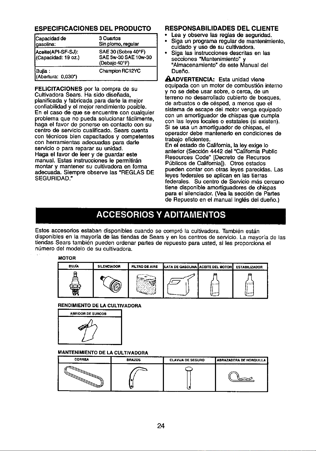
ESPEClFICAClONES DEL PRODUCTO
Capacidad de
9asolina:
Aceite(API-SF-SJ):
(Capacidad: 19 oz.)
Bujia :
(Abertura: 0,030")
3 Cuartos
Sin plomo,reQular
SAE 30 (Sobre 40°F)
SAE 5w-30 SAE 10w-30
(Debajo 40°F)
ChampionRC12YC
FELICITACIONES por la compra de su
Cultivadora Sears. Ha sido diseSada,
planificada y fabricada para dade la mejor
confiabilidady el mejor rendimiento posible.
En el caso de que se encuentre con cualquier
problema que no pueda solucionar f_.ciimente,
haga el favor de ponerse en contacto con su
centro de servicio cualificado. Sears cuenta
con t6cnicos bien capacitados y competentes
con herramientas adecuadas para dade
servicio o para reparar su unidad.
Haga el favor de leer y de guardar este
manual. Estas instrucciones le permitirdn
montar y mantener su cultivadora en forma
adecuada. Siempre observe las "REGLAS DE
SEGURIDAD."
RESPONSABILIDADES DEL CLIENTE
• Lea y observe las reglas de seguridad.
• Siga un programa regular de mantenimiento,
cuidado y uso de su cultivadora.
• Siga las instrucciones descritas en las
secciones =Mantenimiento" y
"Almacenamiento" de este Manual del
DueSo.
_,ADVERTENClA: Esta unidad viene
equipada con un motor de combusti6n intemo
y no se debe usar sobre, o cerca, de un
terreno no desarrollado cubierto de bosques,
de arbustos o de c6sped, a menos que el
sistema de escape del motor venga equipado
con un amortiguador de chispas que cumpla
con las leyes locales o estatales (si existen).
Si se usa un amortiguador de chispas, el
operador debe mantenerlo en condiciones de
trabajo eficientes.
En el estado de California, la ley exige Io
anterior (Secci6n 4442 del "California Public
Resources Code" [Decreto de Recursos
P_blicos de California]). Otros estados
pueden contar con otras leyes parecidas. Las
leyes federales se aplican en las tierras
federales. Su centro de Servicio m_.scercano
tiene disponible amortiguadores de chispas
para el silenciador. (Vea la secci6n de Partes
de Repuesto en el manual Ingles del dueSo.)
Estos accesorios estaban disponibles cuando se compr6 la cultivadora. Tambi6n estdn
disponibles en la mayorfa de las tiendas de Sears yen los centros de servicio. La mayor[a de las
tiendas Sears tambi6n pueden ordenar partes de repuesto para usted, si les proporciona el
nSmero del modelo de su cultivadora.
MOTOR
BU_A
SILENCtADOR FILTRO DE AIRE LATA DE GASOUN_ ACEITE DEL MOTOR ESTABIUZADOR
RENDIMIENTO DE LA CULTIVADORA
ABR_DOR DE SURCOS
MANTENIMIENTO DE LA CULTIVADORA
CORREA BRAZOS CLAVlJA DE SEGURO ABRAZADERA DE HORQUILLA
24
Su cultivadora nueva ha sido montada en la
fdbdca, con la excepci6n de aquellas partes
que se dejaron sin montar pot razones de
envio. Para asegurarse que la cultivadora
operarb en torma segura y adecuada, todas
las partes y los artfculos de ferreteria que
monte tienen que estar apretados en forma
segura. Use las herramientas correctas,
segdn sea necesado, para asegurarse de que
queden apretadas en forma segura.
HERRAMIENTAS NECESARIAS PARA
EL MONTAJE
Sele facilitardel montaje si cuenta con un
juego de Ilaves de tubo. Se han enumerado los
tamafios estdndar de las Ilaves.
(1) Cuchillo para todo uso
(1) Cortador de alambres
(1) Destornillador
(1) Medidor de presi6n de las Ilantas
(1) Par de alicates
(1) Llave de 9/16"
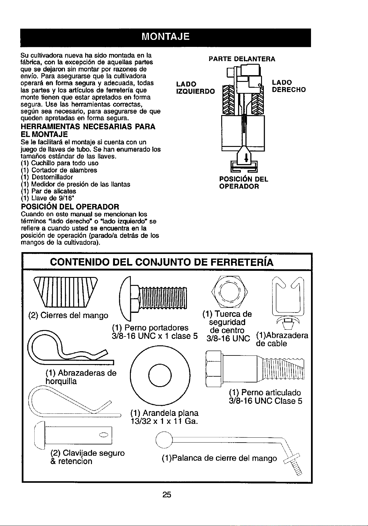
POSICI(3N DEL OPERADOR
Cuando en oste manual se mencionan los
tdrminos "lado derecho" o =lado izquierdo" se
refiere a cuando usted se encuentra en la
posici6n de operaci6n (parado/a detrds de los
mangos de la cultivadora).
PARTE DELANTERA
LADO LADO
IZQUIERDO DERECHO
POSICI6N DEL
OPERADOR
CONTENIDO DEL CONJUNTO DE FERRETERfA
/llllll/Y
(2) Cierres del mango
(1) Abrazaderas de
horquilla
(2) Clavijade seguro
& retencion
(1) Perno portadores
3/8-16 UNC x 1 clase 5
(1) Arandela plana
13/32 x 1 x 11 Ga.
©
(1) Tuerca de
seguridad
de centro
3/8-16 UNC
(1)Abrazadera
de cable
(1) Perno articulado
3/8-16 UNC Clase 5
©
(1)Palanca de cierre del mango _F.__
25
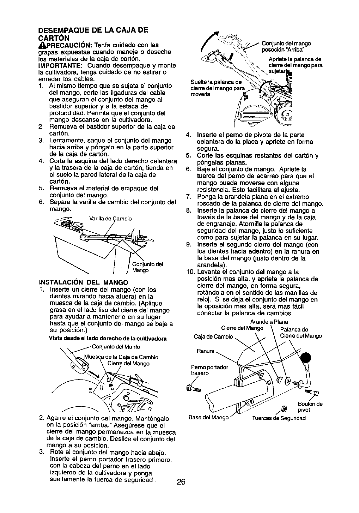
DESEMPAQUE DE LA CAJA DE
CART6N
_PRECAUCION: Tenfa cuidado con las
grapas expuestas cuando maneje o deseche
los matedales de la caja de cart6n.
IMPORTANTE: Cuando desempaque y monte
la cultivadora, tenga cuidado de no estirar o
enredar los cables.
1. AI mismo tiempo que se sujeta el conjunto
del mango, corte las ligaduras del cable
que aseguran el conjunto del mango al
bastidor superior y a la estaca de
profundidad. Permita que el conjuntodel
mango descanse en la cultivadora.
2. Remueva el bastidor superior de la caja de
cart6n.
3. Lentamente, saque el conjunto del mango
hacia arriba y p6ngalo en la parte superior
de la caja de cart6n.
4. Corte la esquina del lado derecho delantera
y la trasera de la caja de cartbn, tienda en
el suelo la pared lateral de la caja de
cart6n.
5. Remueva el material de empaque del
conjunto del mango.
6. Separe la varilla de cambio del conjuntodel
mango.
Varillade(
Conjunto del
Mango
INSTALACI(_N DEL MANGO
1. Inserte un cierre del mango (con los
dientes mirando hacia afuera) en la
muesca de la caja de cambio. (Aplique
grasa en el lado liso del cierre del mango
para ayudar a mantenerlo en su lugar
basra que el conjunto del mango se baje a
su posici6n.)
Vistadesdeelladoderechodela cultlvadora
_X_MMuConjunto delManfo
escadela CajadeCambio
_._ _ Cierr/edel Mango
2. Agarre el conjunte del mango. Mant6ngalo
en la posicidn _ardba." Aseg_rese que el
cierre del mango permanezca en la muesca
de la caja de cambio. Deslice el conjunto del
mango a su posici6n.
3. Rote el conjunto del mango hacia abajo.
Inserte el perno portador trasero primero,
con la cabeza del perno en el lado
izquierdo de la cultivadora y ponga
sueltamente la tuerca de seguridad.
26
posoci6n"Arriba"
"i:i',,_:' Aprietelapalancade
m
'. ,::_. cierredelmangopara
Suelta la
cierra del mango para
moveda
4. Inserte el perno de pivote de la parte
delantera de la placa y apriete en forma
segura.
5. Corte las esquinas restantes del cart6n y
p6ngalas planas.
6. Baje el conjunto de mango. Apriete la
tuerca del pemo de acarreo para que el
mango pueda moverse con alguna
resistencia. Esto facilitara el ajuste.
7. Ponga la arandela plana en el extremo
roscado de la palanca de cierre del mango.
8. Inserte la palanca de cierre del mango a
trav6s de la base del mango y de la caja
de engranaje. Atornillela palanca de
seguridad del mango, justo Io suficiente
como para sujetar la palanca en su lugar.
9. Inserte el segundo cierre del mango (con
los dientes hacia adentro) en la ranura en
la base del mango (justo dentre de la
arandela).
10. Levante el conjunto del mango a la
posici6n mas alta, y apriete la palanca de
cierre del mango, en forma segura,
rot&ndolaen el sentido de las manillas del
reloj. Si se deja el conjunto del mango en
la oposici6n mas alta, ser& mas f_.cil
conectar la palanca de cambios.
ArandelaPlana
CierredelMango Palancade
CajadeCambio CierredalMango
Ranura
Perno portador
trasero
Base del Mang(
Boulonde
/_ pivot
Tuercasde Seguridad
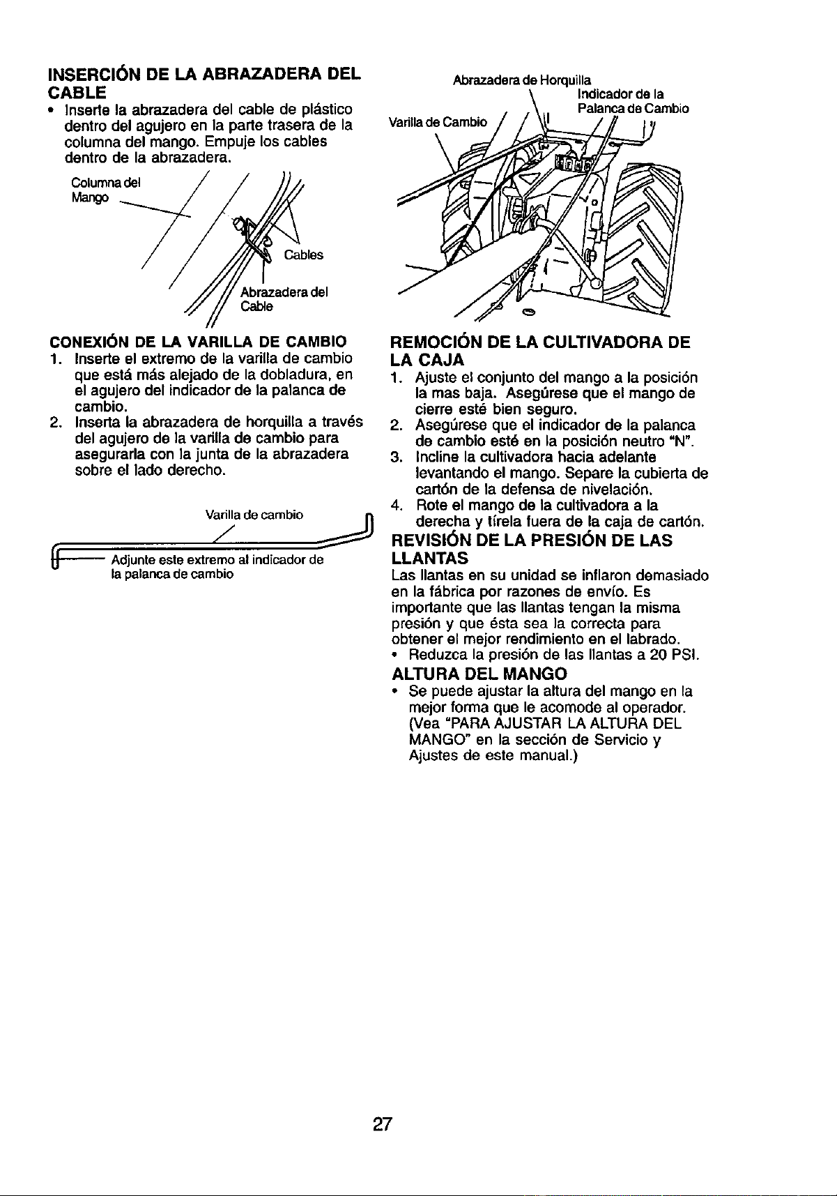
INSERCI(_N DE LA ABRAZADERA DEL
CABLE
• Inserte la abrazadera del cable de pldstico
dentin del agujem en la parte trasera de la
columna del mango. Empuje los cables
dentro de la abrazadera.
Columnadel
Mango
Abrazadera de Horquilla
Indicadorde la
Palancade Cambio
Varillade Cambio
CabEes
Abrazaderadel
Cable
CONEXI(_N DE LA VARILLA DE CAMBIO
1. Inserte el extremo de la varilla de cambio
que estd m_,salejado de la dobladura, en
el agujero del indicaclorde la palanca de
cambio.
2. Inserta la abrazadera de horquilla a travds
del agujero de la varilla de cambio para
asegurarla con la junta de la abrazadera
sobre el lado derecho.
Varilladecambio
_'-'--- Adjunteesteextremoal indicadorde
la palancadecambio
REMOCION DE LA CULTIVADORA DE
LA CAJA
1. Ajuste el conjunto del mango a la posici6n
lamas baja. Asegdrese que el mango de
cierre est_ bien seguro.
2. AsegSrese que el indicador de la palanca
de cambio est6 en la posici6n neutro "N",
3. Incline la cultivadora hacia adelante
levantando el mango. Separe la cubierta de
cart6n de la defensa de nivelaci6n.
4. Rote el mango de la cultivadora a la
derecha y t(rela fuera de la caja de cart6n.
REVISI6N DE LA PRESI6N DE LAS
LLANTAS
Las Ilantas en su unidad se inflaron demasiado
en la fabrica por razones de envfo. Es
importante que las Ilantas tengan la misma
presi6n y que dsta sea la correcta para
obtener el mejor rendimientoen el labrado.
• Reduzca la presi6n de las Ilantas a 20 PSI.
ALTURA DEL MANGO
• Se puede ajustar la altura del mango en la
mejorforma que le acomode al operador.
(Vea "PARAAJUSTAR LA ALTURA DEL
MANGO" en la secci6n de Servicio y
Ajustes de este manual.)
27
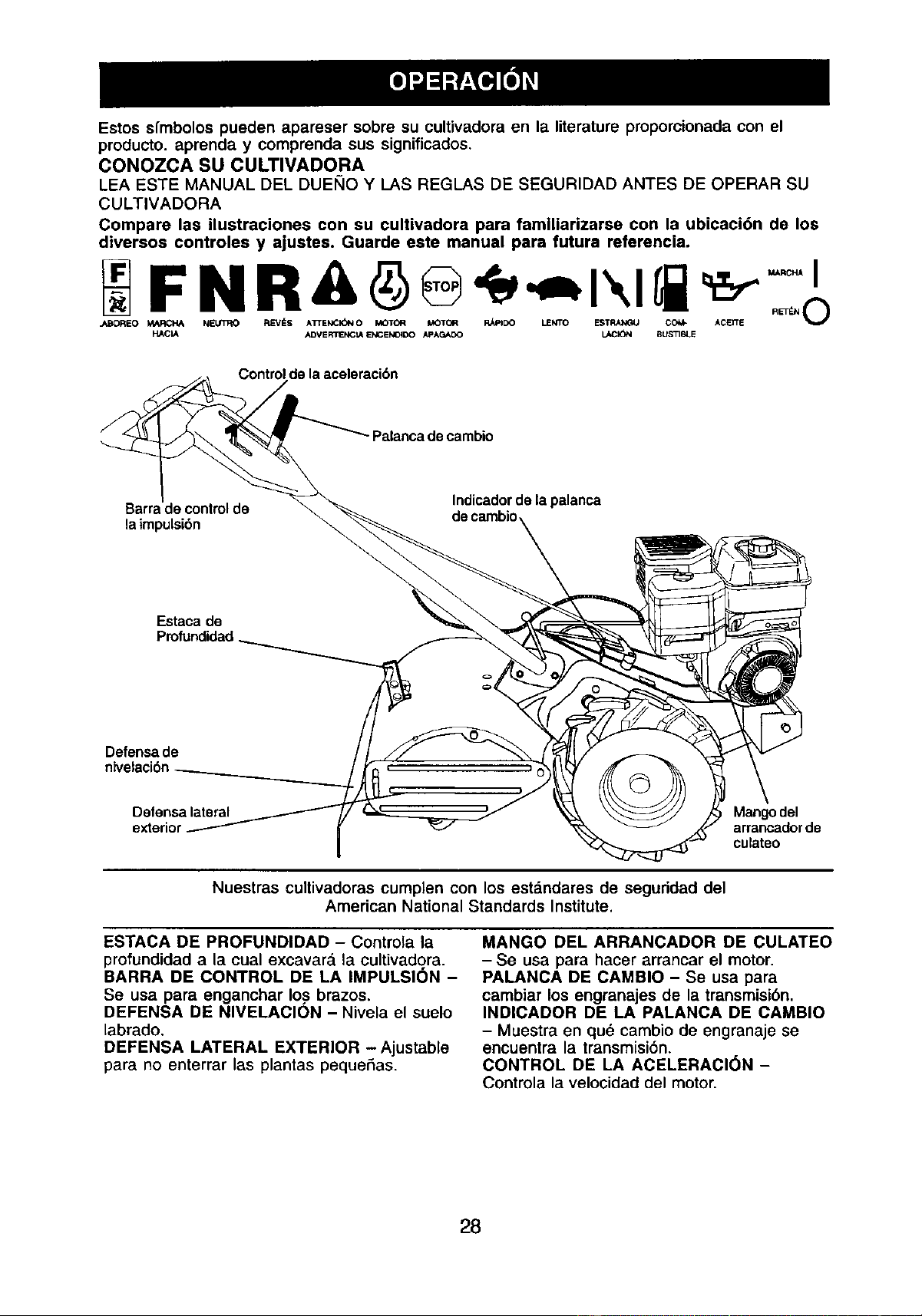
Estos s{mbolos pueden apareser sobre su cultivadora en la literature propomionada con el
producto, aprenda y comprenda sus significados.
CONOZCA SU CULTIVADORA
LEA ESTE MANUAL DEL DUEI_IOY I_ASREGLAS DE SEGURIDAD ANTES DE OPERAR SU
CULTIVADORA
Compare las ilustraciones con su cultivadora para famlliarizarse con la ubicaci6n de los
diversoa controles y ajustes. Guarde este manual para futura referencla.
F N R&
J_BOREO MARCH& NELR3_O RLcVI_S A_ENC_N O MOTOR M_OI[QR R_pI[X_ MENTO ESTRANGU C(_ ACI_E RL=TI_N _lJ
HACIA ADVER1PENClA ENCENO_DO APAGAOO LACI(_N BUSTIBLE
Control de la aceleraci6n
Palanca de cambio
Barra de controlde
la impulsibn
Indicadorde la palanca
de cambio
Estaca de
Profundidad
Defensa de
nivelacibn
Defensalateral
Mangodel
arrancadorde
culateo
Nuestras cultivadoras cumplen con los estdndares de seguridad del
American National Standards Institute.
ESTACA DE PROFUNDIDAD - Controla la
profundidad a la cual excavar_, la cultivado.ra.
BARRA DE CONTROL DE LA IMPULSION -
Se usa para enganchar Io.sbrazos.
DEFENSA DE NIVELAClON - Nivela el suelo
labrado.
DEFENSA LATERAL EXTERIOR -Ajustable
para no enterrar las plantas peque£tas.
MANGO DEL ARRANCADOR DE CULATEO
- Se usa para hacer arrancar el motor.
PALANCA DE CAMBIO - Se usa para
cambiar los engranajes de la transmisi6n,
INDICADOR DE LA PALANCA DE CAMBIO
- Muestra en qu_ cambio de engranaje se
encuentra la transmisi6n.
CONTROL DE LA ACELERACI(_N -
Controla la velocidad del motor.
28
La operacibn de cualquier cultivadora puede hacer que salten objetos extraSos
dentre de sus ojos, Io que puede producirda_os graves en _stos. Siempre use
anteojos de seguridad o protecciones para los ojos antes de hacer arrancar su
cultivadora o mientras est_ labrando con dlla. Recomendamos el uso de la
mdscara de seguddad de visi6n amplia, para uso sobre los espejuelos o anteojos
de seguridad estdndar.
COMO USAR SU CULTIVADORA
Sepa c6mo operar todos los contreles antes
de agregar combustible y aceite o antes de
tratar de hacer arrancar el motor.
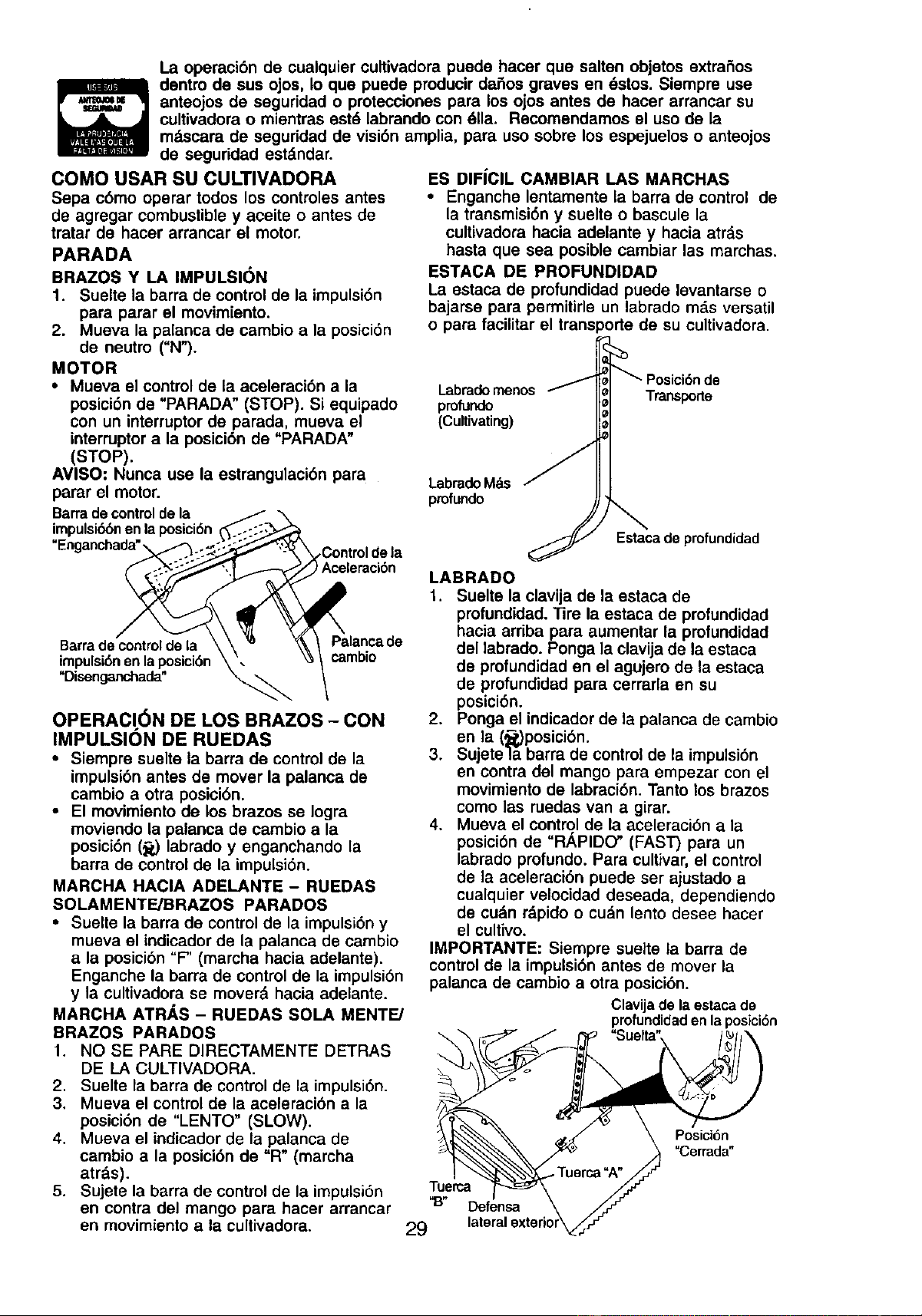
PARADA
BRAZOS Y LA IMPULSION
1. Suelte la barra de control de la impulsi6n
para parar el movimiento.
2. Mueva la palanca de cambio a la posici6n
de neutro ("N").
MOTOR
• Mueva el control de la aceleraci6n a la
posici6nde "PARADA" (STOP). Si equipado
con un interruptorde parada, mueva el
interruptora la posici6n de "PARADA"
(STOP).
AVISO: Nunca use la estrangulaci6n para
parar el motor.
Barradecontroldela _ \
impulsi(_bnenla posici6n_.::-:,_._
"Enganchada"_-/_. S-_"-_"_ Controldela
leraci6n
Barrada'controldela \\ _ _k_ Palancade
!mpulsi6nen laposici6n\\ _ / cambio
OPERACI6N DE LOS BRAZOS - CON
IMPULSION DE RUEDAS
• Siempre suelte la barra de control de la
impulsi6n antes de mover la palanca de
cambio a otra posici6n.
• El movimiento de los brazos se Iogra
moviendo la palanca de cambio a la
posici6n (_,) labredo y enganchando la
barra de control de la impulsi6n.
MARCHA HAClA ADELANTE - RUEDAS
SOLAMENTE/BRAZOS PARADOS
• Suelte la barra de control de la impulsi6ny
mueva el indicador de la palanca de cambio
a la posicibn"F" (marcha hacia adelante).
Enganche la barra de control de la impulsi6n
y la cultivadora se mover& hacia adelante.
MARCHA ATR_,S - RUEDAS SOLA MENTE/
BRAZOS PARADOS
1. NO SE PARE DIRECTAMENTE DETRAS
DE LA CULTIVADORA.
2. Suelte la barra de control de la impulsi6n.
3. Mueva el controlde la aceleraci6n a la
posici6n de "LENTO" (SLOW).
4. Mueva el indicadorde la palanca de
cambio a la posici6n de "R" (marcha
atrds).
5. Sujete la barra de control de la impulsi6n
en contra del mango para hacer arrancar
en movimiento a la cultivadora.
ES DIFiCIL CAMBIAR LAS MARCHAS
• Enganche lentamente la barra de control de
la transmisi6n y suelte o bascule la
cultivadora hacia adelante y hacia atrds
hasta que sea posible cambiar las marchas.
ESTACA DE PROFUNDIDAD
La estaca de profundidad puede levantarse o
bajarse para permitirle un labrado m_,s versatil
o para facilitar el transporte de su cultivadora.
Labradomenos
profundo
(Cultivating)
Transporte
LabradoMds
profundo
Estacade profundidad
LABRADO
1. Suelte la clavija de la estaca de
profundidad. ]ire la estaca de profundidad
hacia arriba para aumentar la profundidad
del labredo. Ponga la clavija de la estaca
de profundidad en el agujere de la estaca
de profundidad para cerrarla en su
posici6n.
2. Ponga el indicadorde la palanca de cambio
en la (_,)posici6n.
3. Sujetela barra de control de la impulsi6n
en contra del mango para empezar con el
movimiento de labraci6n. Tanto los brazos
como las ruedas van a girar.
4. Mueva el control de la aceleraci6n a la
posici6n de =R,_PIDO" (FAST) para un
labracloprofundo. Pare cultivar, el control
de la aceleraci6n puede set ajustado a
cualquier velocidad deseada, dependiendo
de cudn rdpido o cu_n lento desee hacer
el cultivo.
IMPORTANTE: Siempre suelte la barra de
controlde la impulsi6n antes de mover la
palanca de cambio a otra posici6n.
Clavijadelaestacade
profundidadenlaposici6n
"Suelta"
muerca
"13" Defensa
29 laterali
Posici6n
"Cerrada"
GIRO
1. Suelte la barra de control de la impulsi6n.
2. Mueva el control de la aceleraci6n a la
posici6n de "LENTO" (SLOW).
3. Ponga ei indicador de la palanca de cambio
en la posici6n de "F" (marcha hacia
adelante). Los brazos no van a girar.
4. Levante el mango para levantar los brazos
fuera del suelo.
5, Mueva el mango en la direcci6n opuesta
en la que desea girar, con cuidado de
mantener los pies y las piernas alejados
de los brazos de la cultivadora.
6. Cuando haya completado su vuelta, suelte
la barra de control de la impulsi6ny baje el
mango. Ponga la palanca de cambio en la
posici6n labrado y mueva el control de la
aceleraci6n a la velocidad deseada. Para
empezar a cultivar, sujete la barra de
controlde la impulsi6n en contra del
mango.
DEFENSAS LATERALES EXTERIORES
Los hordes trasero de las defensas laterales
extedores son rasurados de modo que 6stas
se puedan levantar para hacer un labrado
profundo y bajar para uno poco profundo, para
evitar enterrar las plantas pequeSas.
1. Suelte la tuerca =A" en la ranura y la tuerca
ugh"
2. Mueva la defensa a la posici6n deseada
(en ambos lados).
3. Vuelva a apretar las tuercas.
PARA EL TRANSPORTE
_I_PRECAUCI6N: Antes de levantarla o
transportarla, permita que el motor de la
cultivadora y el silenciador se enfrfen.
Desconecte el alambre de la bujia. Drene la
gasolina del estanque de combustible.
EN EL JARD|N
1. Suelte la clavija de la estaca de
profundidad. Mueva la estaca de
profundidad hacia abajo, al agujero
superior, para transportar la cultivadora.
Ponga la clavija de la estaca de profundi-
dad en el agujero de la estaca de
profundidad para asegurarla en su lugar.
Esto impide que los brazos se arrastren
por et suelo.
2. Ponga el indicador de la palanca de cambio
en la posici6n de =F" (marcha hacia
adelante) para el transporte.
3. Sujete la barra de controlde la impulsi6n
en contra del mango para empezar con el
movimiento de la cultivadora. Los brazos
no van a girar.
4. Mueva el control de la aceleraci6n a la
velocidad deseada.
EN LA CIUDAD
1. Desconecte el alambre de la buj_a.
2. Drene el estanque de combustible.
3. Transp6rtela en la posici6n derecha hacia
arriba para evitar la fuga del aceite.
ANTES DE HACER ARRANCAR EL
MOTOR
IMPORTANTE: Tenga mucho cuidado de no
permitir que entre mugre al motor cuando
revise o a_ada aceite o combustible. Use
aceite y combustible limpiosy gudrdelos en
envases aprobados, limpios y con tapa. use
embudos para relleno limpios.
REVISION DEL NIVEL DEL ACEITE DEL
MOTOR
El motor en su unidad ha sido enviado desde
la fabrica Ileno con aceite de calidad para el
verano SAE 30.
1. Con el motor nivelado, limpie un _,rea
alrededor del tap6n del dep6sito para
relleno del aceite y remueva el tap6n.
2. Con el motor nivelado, d aceite del motor
debe Ilegar hasta el punto de derramarse.
• Para verificar la capacidad aproximada yea
=ESPECIFICACIONES DEL PRODUCTO"
en la pdgina 24 de este manual. Todo el
aceite tiene que cumplir la clasificaci6n de
servicio API SF o SJ.
• Para la operaci6n en clima frfo, debe
cambiarse el aceite para facilitar el arranque
(yea la "T'ABLA DE VISCOSIDAD DEL
ACEITE-" en la secci6n de Mantenimiento en
este manual).
• Para cambiar el aceite del motor, yea la
secci6n de Mantenimiento en este manual.
Tap6nde depositode :P_'-,_
rellenodeaceite
AGREGUE GASOLINA
• Llene el estanque de combustible. Use
gasolina regular, sin ptomo, nueva y Umpia.
(El uso de gasolina con plomo aumentar_,
los dep6sitos de 6xido de plomo y carbono
y se reducir_,la duraci6n de la v._lvula.)
IMPORTANTE: Cuando se opere en
temperaturas por debajo de 32°F (0°C) use
gasolina de calidad de invierno, limpia y nueva
para ayudar a asegurar un buen arranque en
clima fHo.
• IJ_DVERTENClA: La experiencia ha indicado
que los combustibles mezclados con alcohol
(conocidos como gasohol, o el uso de etanol o
metanol) pueden atraer la humedad, la que
conduce a la separaci6n y formaci6n de
dcidos durante el almacenamiento. La gasolina
acidica puede dahar el sistema del combus-
tiblede un motor durante el almacenamiento.
Para evitar problemas con el motor, se
debe vaciar el sistema de combustible
antes de guardarlo por un periodo de 30
dias o rods. Vacie el estanque de combus-
tible, haga arrancar el motor y hdgalo
funcionar hasta que las lineas del combustible
3O
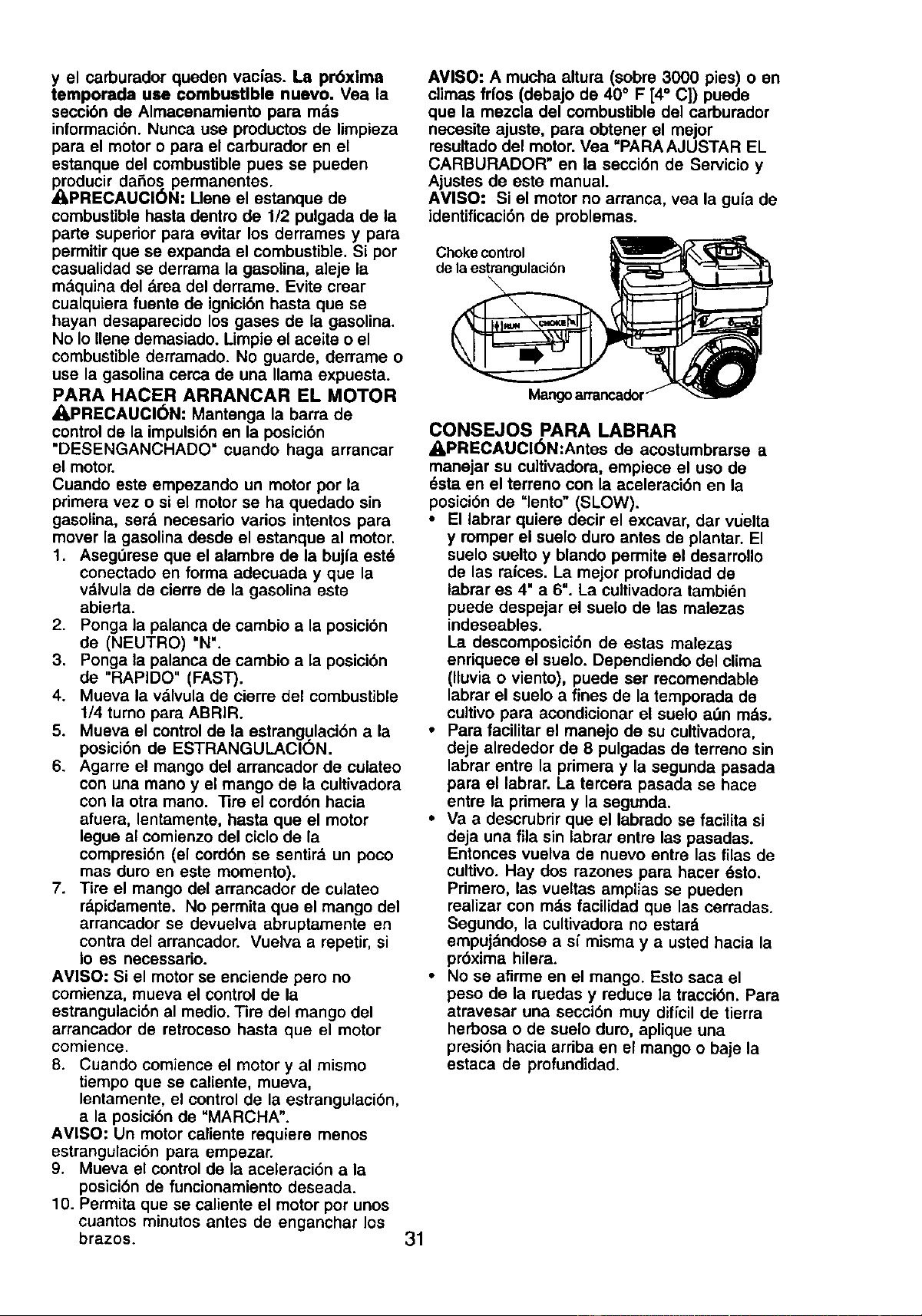
y el carbumdor queden vacias. La pr6xlma
temporada use combustible nuevo. Vea ia
secci6n de Almacenamiento para rods
informaci6n. Nunca use productos de limpieza
para el motor o para el carburador on el
estanque del combustible pues se pueden
Rroducir dafios permanentes.
_I,PRECAUCl6N: Llene el estanque de
combustible hasta dentro de 1/2 pulgada de la
parte superior para evitar los derrames y para
permitirque se expanda el combustible. Si pot
casualidad se derrama la gasolina, aleje la
mdquina del area del derrame. Evite crear
cualquiera fuente de ignici6n hasta que so
hayan desaparecido los gases de la gasolina.
No Io Ilene demasiado. Limpie el aceite o el
combustible derramado. No guarde, derrame o
use la gasolina cerca de una llama expuesta.
PARA HACER ARRANCAR EL MOTOR
_I,PRECAUCI(_N: Mantenga la barra de
controlde la impulsi6n en la posicibn
"DESENGANCHADO" cuando haga arrancar
el motor.
Cuando este empezando un motor pot la
primera vez o si el motor se ha quedado sin
gasolina, serd necesario varios intentos para
mover la gasolina desde el estanque al motor,
1. AsegOrese que el alambre de la bujla est_
conectado on forma adecuada y que la
vdlvula de cierre de la gasolina este
abierta.
2. Ponga la palanca de cambio a la posici6n
de (NEUTRO) "N".
3. Ponga la palanca de cambio a la posici6n
de "RAPIDO" (FAST).
4. Mueva la valvula de cierre del combustible
1/4 tumo para ABRIR.
5. Mueva el control de la estrangulacibn a la
posici6n de ESTRANGULACI(_N.
6. Agarre el mango del arrancador de culateo
con una mano y el mango de la cultivadora
con la otra mano. ]]re el cord6n hacia
afuera, lentamente, hasta que el motor
legue al comienzo del ciclo de la
compresi6n (el cord6n se sentird un poco
mas duro en este momento).
7. Tire el mango del arrancador de culateo
rdpidamente. No permita que el mango del
arrancador se devuelva abruptamente en
contra del arrancador. Vuelva a repetir, si
Io es necessario.
AVISO: Si el motor se enciende pero no
comienza, mueva el control de la
estrangulaci6n al medio. Tire del mango del
arrancador de retroceso hasta que el motor
comience.
8. Cuando comience el motor y al mismo
tiempo que se caliente, mueva,
lentamente, el control de la estrangulaci6n,
a la posici6n de "MARCHA".
AMISO: Un motor caliente requiem menos
estrangulaci6n para empezar.
9. Mueva el control de la aceleraci6n a la
posici6n de funcionamiento deseada.
10. Permita que se caliente el motor por unos
cuantos minutos anles de enganchar los
brazos.
AVISO: A mucha altura (sobre 3000 pies) o en
climas frfos (debajo de 40° F [4° C]) puede
que la mezcla del combustible del carburador
necesite ajuste, para obtener el mejor
resultadodel motor.Vea "PARA AJUSTAR EL
CARBURADOR" en la secci6n de Servicio y
Ajustes de este manual.
AVISO: Si el motor no arranca, vea la guia de
identificaci6n de problemas.
31
Choke control
de la estrangulaci6n
Mangoarrancador
CONSEJOS PARA LABRAR
,APRECAUCI(_N:Antes de acostumbrarse a
manejar su cultivadora, empiece el uso de
_sta en el terreno con la aceleraci6n en la
posici6n do "lento" (SLOW).
• El labrar quiere decir el excavar, dar vuelta
y romper el suelo duro antes de plantar. El
suelo suelto y blando permite el desarrollo
de las raices. La mejor profundidad de
labrar es 4" a 6". La cultivadora tambidn
puede despejar el suelo de las malezas
indeseables.
La descomposici6n de estas malezas
enriquece el suelo. Dependiendo del clima
(lluvia o viento), puede set recomendable
labrar el suelo a fines de la temporada de
cultivo para acondicionar el suelo a_n mds.
• Para facilitar el manejo de su cultivadora,
deje alrededor de 8 pulgadas de terreno sin
labrar entre la primera y la segunda pasada
para el labrar. La tercera pasada se hace
entre la primera y la segunda.
• Va a descrubdr que el labrado se facilita si
deja una ilia sin labrar entre las pasadas.
Entonces vuelva de nuevo entre las filas de
cultivo. Hay dos razones para hacer dsto.
Primero, las vueltas amplias so pueden
realizar con rods facilidad que las cerradas.
Segundo, la cultivadora no estard
empuj_.ndosea sf misma y a usted hacia la
pr6xima hilera.
• No se afirme en el mango. Esto saca el
peso de la ruedas y reduce la tracci6n. Para
atravesar una seccibn mW diflcil de tierra
herbosa o de suelo duro, aplique una
presi6n hacia arriba en el mango o baje la
estaca de profundidad.
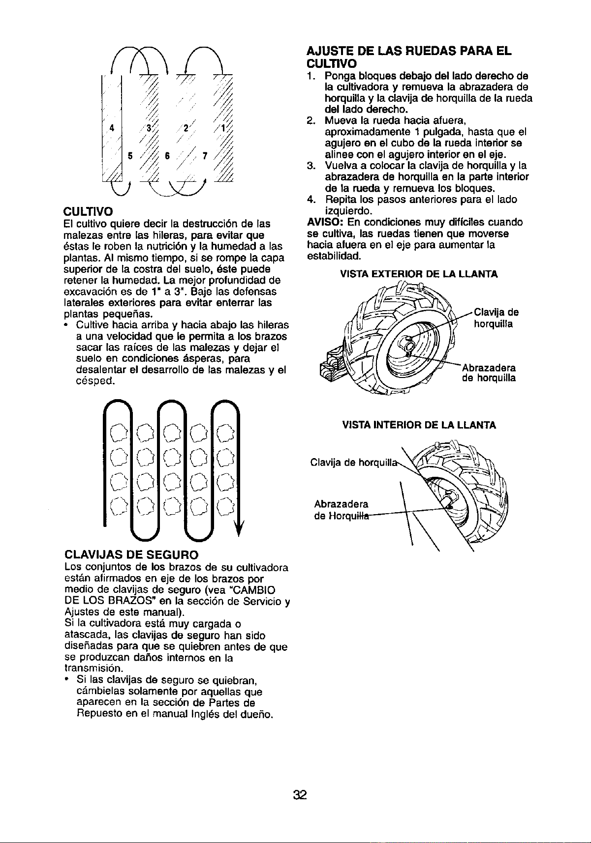
CULTIVO
El cultivo quiere decir la destrucci6n de las
malezas entre las hileras, para evitar que
_stas le robert la nutrici6ny la humedad alas
plantas. AI mismo tiempo, si se rompe la capa
superior de la costra del suelo, _ste puede
retener la humedad. La mejor profundidad de
excavaci6n es de 1" a 3". Baje las defensas
laterales exteriores para evitar enterrar las
plantas pequeSas.
• Cultive hacia arriba y hacia abajo las hileras
a una velocidad que le permita a los brazos
sacar las raices de las malezas y dejar el
suelo en condiciones dsperas, para
desalentar el desarrollo de las malezas y el
c_sped.
CLAVIJAS DE SEGURO
Los conjuntos de los brazes de su cultivadora
est_.nafirmados en eje de los brazos pot
medio de clavijas de seguro (vea =CAMBIO
DE LOS BRAZOS" en la secci6n de Servicio y
Ajustes de este manual).
Si la cultivadora estd muy cargada o
atascada, las clavijas de seguro han sido
diseSadas para que se quiebren antes de que
se produzcan da,fos internos en la
transmisi6n.
• Si las clavijas de seguro se quiebran,
c&mbielas solamente por aquellas que
aparecen en la secci6n de Panes de
Repuesto en el manual Ingles del dueSo.
AJUSTE DE LAS RUEDAS PARA EL
CULTIVO
I. Ponga bloques debajo del lade derecho de
la cultivadora y remueva la abrazadera de
horquillay la clavija de horquilla de la rueda
del lado derecho.
2. Mueva la rueda hacia afuera,
aproximadamente 1 pulgada, hasta que el
agujero en el cubo de la rueda interior se
alinee con el agujero interior en el eje.
3. Vuelva a colocar la clavija de horquillay la
abrazadera de horquilla en la pane interior
de la rueda y remueva los bloques.
4. Repita los pasos anteriores para el lado
izquierdo.
AVISO: En condiciones muy dificiles cuando
se cultiva, las ruedas tienen que moverse
hacia afuera en el eje para aumentar la
estabilidad.
VISTA EXTERIOR DE LA LLANTA
horquilla
de horquUla
VISTA INTERIOR DE LA LLANTA
Abrazadera
de
32
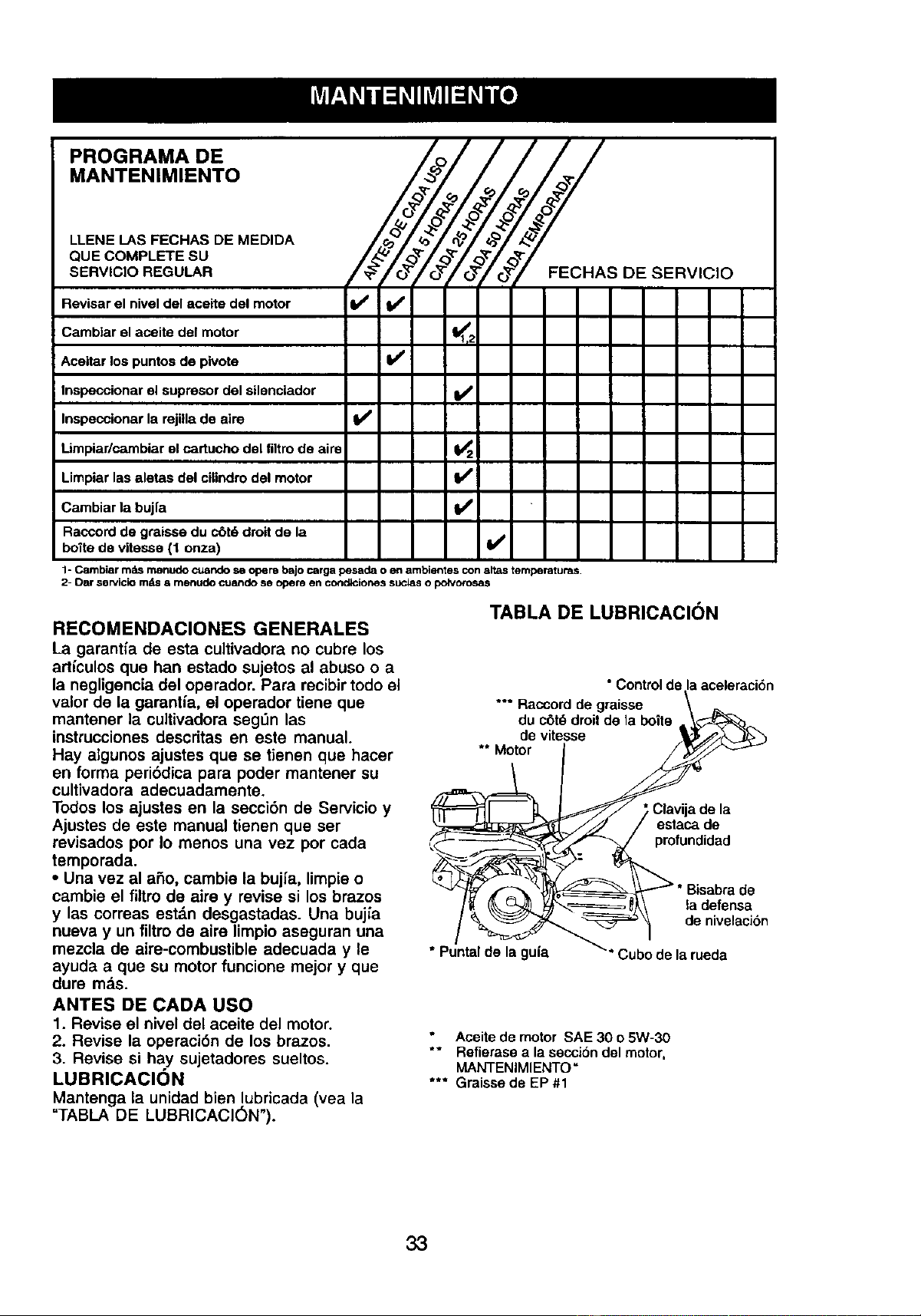
PROGRAMA DE
MANTENIMIENTO
LLENE I-AS FECHAS DE MEDIDA
QUE COMPLETE SU
SERVIClO REGULAR
FECRASDESERV,CIO
Revisar el nivel del aceite del motor It_ I_
Camblar el aceite del motor I_1,=
Aceitar los puntos de pivote Ik/
Inspeccionar el supresor del silonclador I_
Inspeccionar la rejilla de aim I//
Limpiar/cambiar el cartucho del filtro de aire _2
Limpiar las aletas del cilindro del motor I_
Cambiar la bujfa I_
Raccord de graisse du c6t6 dmit de la
botte de vitesse (1 onza) V'
1- Cambiar m=TLSmenudo oJando se opere bajo carga pesada o en ambientes con aitas temperaturas.
2- Dar se P/icio rods a menudo cuando se opera en cot =dlciones sucias o polvorosas
TABLA DE LUBRICACION
RECOMENDACIONES GENERALES
La garantfa de esta cultivadora no cubre los
articulos que ban estado sujetos al abuso o a
la negligencia del operador. Para recibir todo el
valor de la garantia, el operador tiene que
mantener la cultivadora seg_n las
instrucciones descritas en este manual.
Hay algunos ajustes que se tienen que hacer
en forma peri6dica para poder mantener su
cultivadora adecuadamente.
Todos los ajustes en la secci_n de Servicio y
Ajustes de este manual tienen que set
revisados por Io menos una vez pot cada
temporada.
• Una vez al aSo, carnbie la bujfa, limpie o
cambie el filtro de aire y revise si los brazos
y las correas estdn desgastadas. Una buj_a
nueva y un filtro de aire limpio aseguran una
mezcla de aire-combustible adecuada y le
ayuda a que su motor funcione mejor y que
dure mas.
ANTES DE CADA USO
1. Revise el nivel del aceite del motor.
2. Revise la operaci6n de los brazos.
3. Revise si hay sujetadores sueltos.
LUBRICACI(_N
Mantenga la unidad bien lubricada (vea la
"TABLA DE LUBRICACI6N").
* Control de la aceleraciSn
Raccord de graisse \ _,_
*o*
duc6t_droitdela boite•
devitesse '_/_,._
** Motor / _
__'J / estacade
/_ _ _;,_"_.=_=_=__\ la defensa
• Puntal de la Qu[a _'* P.iJhn d_= I_ nJs=t!_
g Cubodela rueda
Aceite de motor SAE 30 o 5W-30
** Rofierase a la secciSndel motor,
MANTENIMIENTO =
*** Graisse de EP#1
33
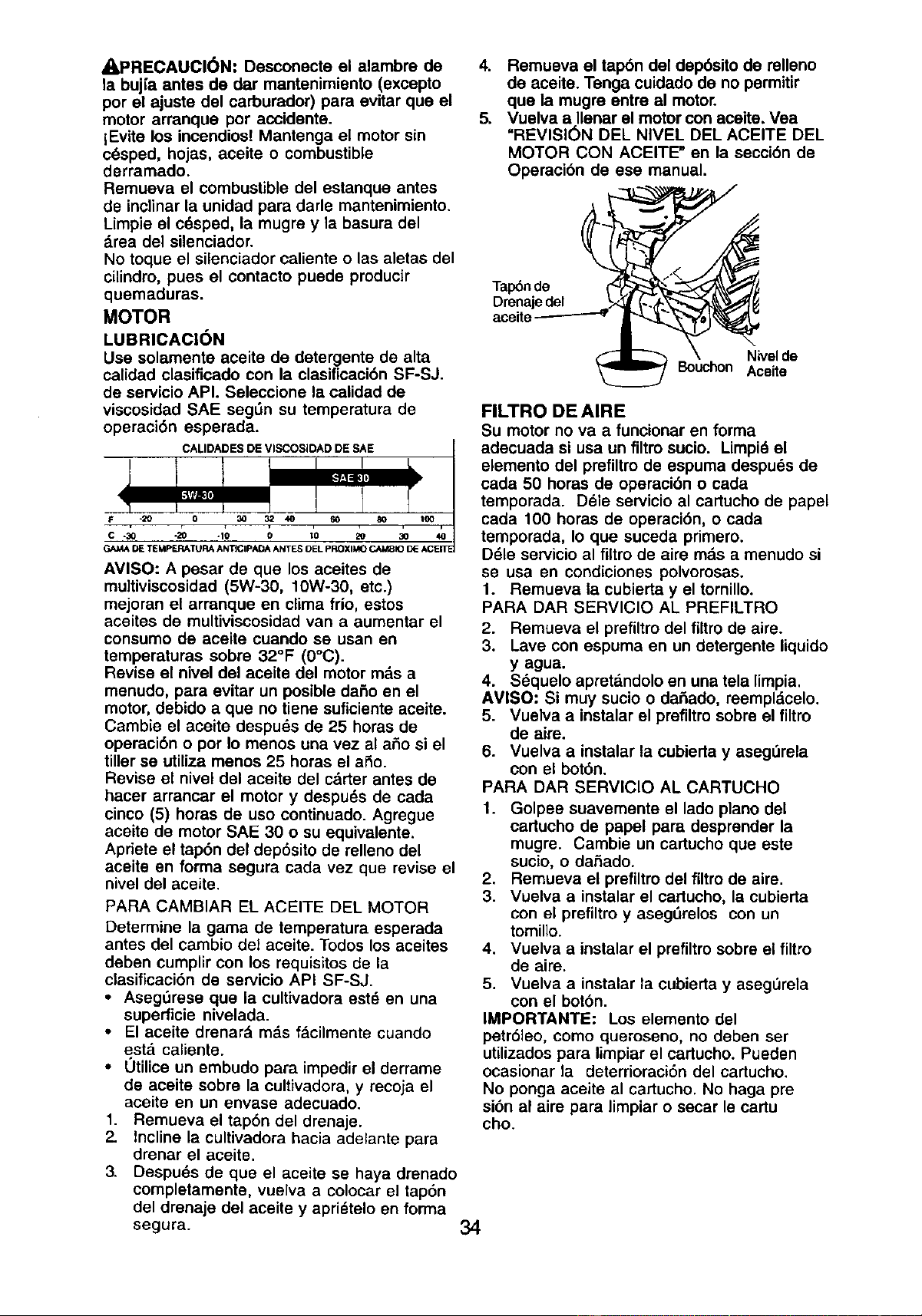
APRECAUCI(_N: Desconecte el alambre de
la bujfa antes de dar mantenimiento (excepto
por el ajuste del carburador) para evitar que el
motor arranque por accidente.
lEvite los incendios! Mantenga el motor sin
cdsped, hojas, aceite o combustible
derramado.
Remueva el combustible del estanque antes
de inclinar la unidad para darle mantenimiento.
Limpie el cdsped, la mugre y la basura del
drea del silenciador.
No toque el silenciador caliente o las aletas del
cilindro, pues el contacto puede producir
quemaduras.
MOTOR
LUBRICAC|(_N
Use solamente aceite de detergente de alta
calidad clasificado con la clasificacidn SF-SJ.
de servicio API. Seleccione la calidad de
viscosidad SAE segOn su temperature de
operacidn esperada.
AVISO: A pesar de que los aceites de
multiviscosidad (5W-30, 10W-30, etc.)
mejoran el arrenque en clima frio, estos
aceites de multiviscosidad van a aumentar el
consumo de aceite cuando se usan en
temperaturas sobre 32°F (0°C).
Revise el nivel del aceite del motor mds a
menudo, para evitar un posible dado en el
motor,debido a que no tiene suficiente aceite.
Cambie el aceite despuds de 25 horas de
operaci6n o por Io menos una vez al ado si el
tillerse utiliza menos 25 horas el ado.
Revise el nivel del aceite del cdrter antes de
hacer arrancar el motor y despuds de cada
cinco (5) horas de uso continuado. Agregue
aceite de motor SAE 30 o su equivalente.
Apriete el tapdn del dep6sito de relleno del
aceite en forma segura carla vez que revise el
nivel del aceite.
PARA CAMBIAR EL ACEITE DEL MOTOR
Determine la gama de temperatura espereda
antes del cambio del aceite. Todos los aceites
deben cumplir con los requisitos de la
clasificacidn de servicio API SF-SJ.
• Asegdrese que la eultivadora estd en una
superficie nivelada.
• El aceite drenard mds f&cilmente cuando
estd caliente.
• Utilice un embudo para impedir el derrame
de aceite sobre la cultivadora, y recoja el
aceite en un envase adecuado.
1. Remueva el tapdn del drenaje.
2. Incline la cultivadora hacia adelante para
drenar el aceite,
3. Despuds de que el aceite se haya drenado
completamente, vuelva a colocar el tapbn
del drenaje del aceite y aprietelo en forma
segura.
4. Remueva el tapbn del depdsito de relleno
de aceite. Tenga cuidado de no permitir
que la mugre entre al motor.
5. Vuelva a Ilenar el motor con aceite. Vea
"REVISI(_N DEL NIVEL DEL ACEITE DEL
MOTOR CON ACEITE" en la secci6n de
Operacibn de ese manual.
Tap_nde
Drenaje del
aceite
Nivel de
Bouchon Aceite
FILTRO DE AIRE
Su motor no va a funcionar en forma
adecuada si usa un filtro sucio. Limpid el
elemento del prefiltro de espuma despuds de
cada 50 horas de operecidn o cada
temporada. Dele servicio al cartucho de papel
cada 100 horas de operacidn, o cada
temporada, Io que suceda primero.
Ddle servicio al filtro de aire mds a menudo si
se usa en condiciones polvorosas.
1. Remueva la cubierta y el tornillo.
PARA DAR SERVlCIO AL PREFILTRO
2. Remueva el prefiltro del filtro de aire.
3. Lave con espuma en un detergente liquido
y agua.
4. Sdquelo apretandolo en una tela limpia.
AVISO: Si muy sucio o dadado, reempldcelo.
5. Vuelva a instalar el prefiltm sobre el firm
de aire.
6. Vuelva a instalar la cubierta y aseg_rela
con el botdn.
PARA DAR SERVICIO AL CARTUCHO
1. Golpee suavemente el lado piano del
cartucho de papel pare desprender la
mugre. Cambie un cartucho que este
sucio, o dadado.
2. Remueva el prefiltrodel filtro de aire.
3. Vuelva a instalar el cartucho, la cubierta
con el prefiltroy aseg_relos con un
tomillo.
4. Vuelva a instalar el prefiltrosobre el filtro
de aire.
5. Vuelva a instalar la cubierta y asegL'Jrela
con el bot6n.
IMPORTANTE: Los elemento del
petrbleo, como queroseno, no deben ser
utUizadospara limpiarel cartucho. Pueden
ocasionar la deterrioraci6n del cartucho.
No ponga aceite al cartucho, No haga pre
sidn al aire para limpiar o secar le cartu
cho.
34
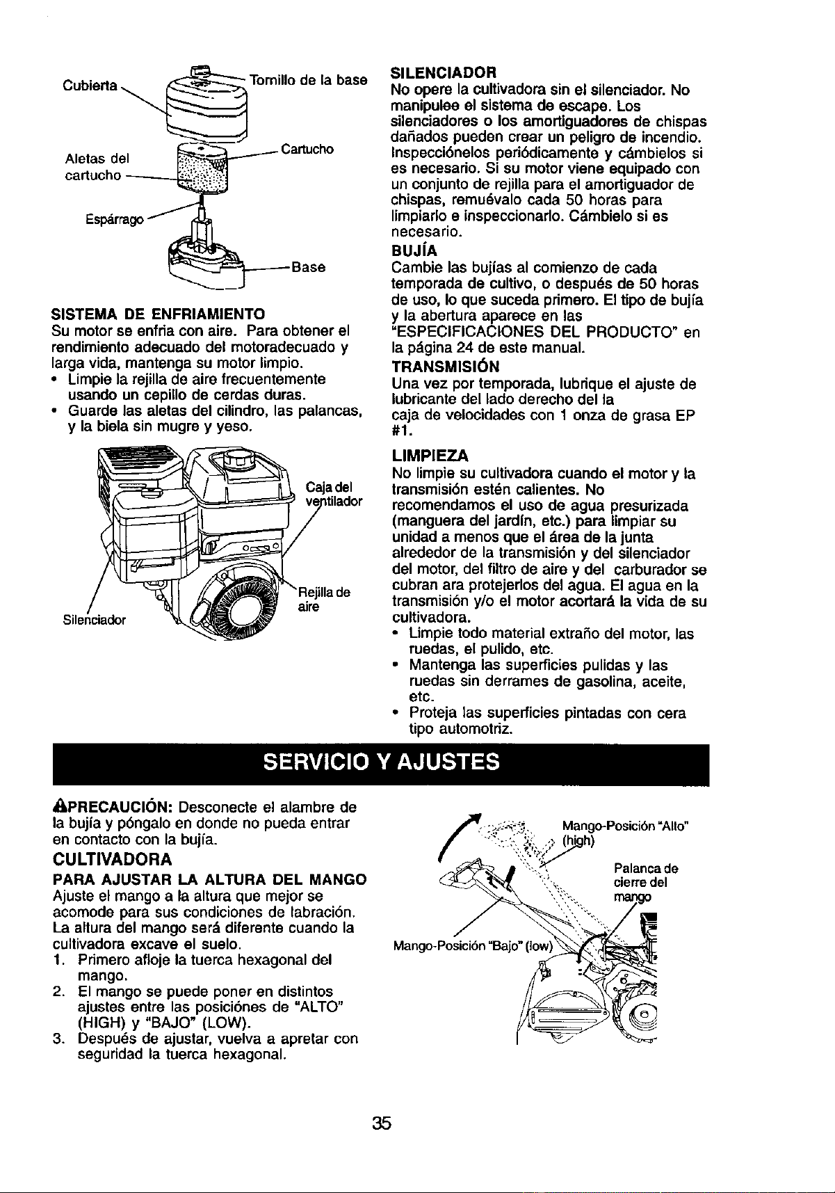
Cubierta_Tornillo de la base
Aletas del _ Cartucho
cartucho _
Espdrragof
_--__ Base
SISTEMA DE ENFRIAMIENTO
Su motor se enfda con aire. Para obtener el
mndimiento adecuado del motoradecuado y
larga vida, mantenga su motor limpio.
• Limpie la rejilla de aire frecuentemente
usando un cepillo de cerdas duras.
• Guarde las aletas del cilindro, las palancas,
y la biela sin mugre y yeso.
Caja del
Silenciador
aire
SlLENClADOR
No opere la cultivadora sin el silenciador. No
manipuloe el sistema de escape. Los
silenciadores o los amortiguadores de chispas
daRados pueden crear un peligro de incendio.
Inspecci6nelos peribdicamente y cdmbielos si
es necesario. Si su motor viene equipado con
un conjunto de rejilla para el amortiguador de
chispas, remu6valo cada 50 horas para
limpiado e inspeccionado. Cdmbielo si es
necesario.
BUJ[A
Cambie las buj{as al comienzo de cada
temporada de cultivo, o despu6s de 50 horas
de uso, Io que suceda primero. El tipo de bujia
y la abertura apareee en las
"ESPEClFICAClONES DEL PRODUCTO" en
la pdgina 24 de este manual.
TRANSMISI6N
Una vez por temporada, lubrique el ajuste de
iubricante del lado derecho del la
caja de velocidades con 1 onza de grasa EP
#1.
LIMPIEZA
No limpie su cultivadora cuando el motor y la
transmisi6n estdn caiientes. No
recomendamos el uso de agua presurizada
(manguera del jardfn, etc.) para limpiar su
unidad a menos que el drea de la junta
alrededor de la transmisi6n y del sileneiador
del motor,del filtrode aim y del carburador se
cubran ara protejerlos del agua. El agua en la
transmisibn y/o el motor acortard,la vida de su
cultivadora.
• Umpie todo material extrafio del motor, las
ruedas, el pulido, eto.
• Mantenga las superficies pulidas y las
ruedas sin derrames de gasolina, aceite,
etc.
• Proteja las superficies pintadas con cera
tipo automotriz.
*q,PRECAUCION: Desconecte el alambre de
la bujfa y p6ngalo en donde no pueda entrar
en contacto con la bujfa.
CULTIVADORA
PARA AJUSTAR LA ALTURA DEL MANGO
Ajusteel mango a la altura qua mejor se
acomode para sus condiciones de labraci6n.
La altura del mango ser_ diferente cuando la
cultivadora excave el suelo.
1. Pdmero afloje la tuerca hexagonal del
mango.
2. El mango se puede poner en distintos
ajustes entre las posiciones de "ALTO"
(HIGH) y "BAJO" (LOW).
3. Despuds de ajustar, vuelva a apretar con
seguridad la tuerca hexagonal.
35
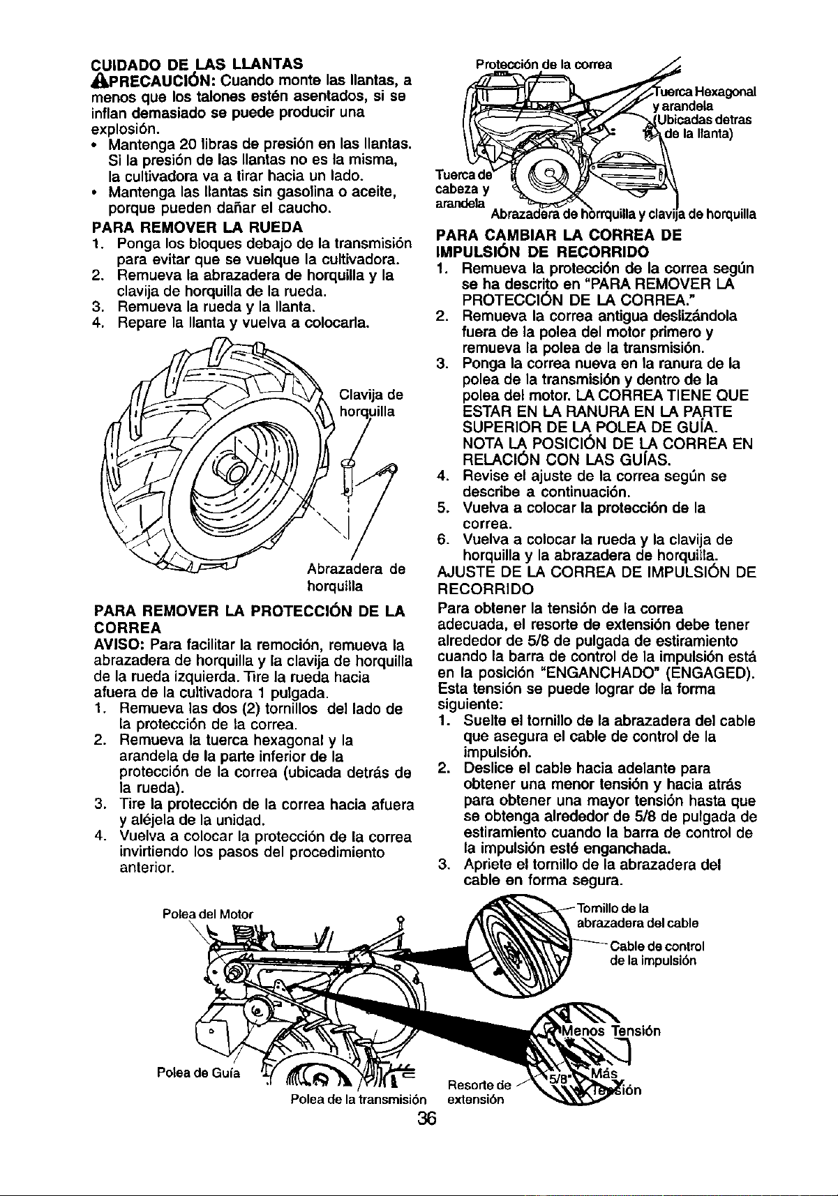
CUIDADO DE LAS LLANTAS
,_PRECAUCI6N: Cuando monte las Ilantas, a
menos que los talones est6n asentados, si se
inflan demasiado se puede producir una
explosibn.
• Mantenga 20 libras de presi6n en las Ilantas.
Si la presi6n de las Ilantas no es la misma,
la cultivadora va a tirar hacia un lado.
• Mantenga las Ilantas sin gasolina o aceite,
porque pueden dafiar el caucho.
PARA REMOVER LA RUEDA
1. Ponga los bloques debajo de la transmisi6n
para evitar que se vuelque la cultivadora.
2. Remueva la abrazadera de horquillay la
clavija de horquillade la rueda.
3. Remueva la rueda y la Ilanta.
4. Repare la Ilanta y vuelva a coloeada.
\
/_ Clavija de
_,\\ horquilla
Abrazadera de
horquilla
PARA REMOVER LA PROTECCION DE LA
CORREA
AVISO: Para facilitar la remoci6n, remueva la
abrazadera de horquilla y la clavija de horquilla
de la rueda izquierda. 33re la rueda hacia
afuera de la cultivadora 1 pulgada.
1. Remueva las dos (2) tomillos del lado de
la protecci6n de la correa.
2. Remueva la tuerca hexagonal y la
arandela de la parte inferiorde la
protecci6n de la correa (ubicada detrds de
la rueda).
3. Tire la protecci6n de la correa hacia afuera
y al6jela de la unidad.
4. Vuelva a colocar la protecci6n de la correa
invirtiendo los pasos del procedimiento
anterior.
Poleadel Motor
\
Protecci6ndela correa ._
_r._ Hexagonal
_ yarandela
[___"_€ ,'__(Ubicadasdetras
e laIlanta)
Tuercade_ _ _ _}_',_=====_\
cabezay %,_ _
arandela
_la Abrazade_mdeh_orrq_illay clavi[adehorquilla
PARA CAMBIAR I..6,CORREA DE
IMPULSI(_N DE RECORRIDO
1. Remueva la protecci6n de la correa seg_n
se ha descrito en "PARA REMOVER LA
PROTECCI6N DE LA CORREA."
2. Remueva la correa antigua desliz&ndola
fuera de la polea del motor pdmero y
remueva la polea de la transmisi6n.
3. Ponga la correa nueva en la ranura de la
polea de la transmisi6n y dentro de la
polea del motor. LA CORREA TIENE QUE
ESTAR EN LA RANURA EN LA PARTE
SUPERIOR DE LA POLEA DE GU[A.
NOTA LA POSICI6N DE LA CORREA EN
RELACI(_N CON LAS GU[AS.
4. Revise el ajuste de la correa segDn se
describe a continuaci6n.
5. Vuelva a colocar la protecci6n de la
correa.
6. Vuelva a colocar la rueda y la clavija de
horquilla y la abrazadera de horquilta.
AJUSTE DE LA CORREA DE IMPULSION DE
RECORRIDO
Para obtener la tensi6n de la correa
adecuada, el resorte de extensi6n debe tener
alrededor de 5/8 de pulgada de estiramiento
cuando la barra de control de la impulsi6n estd
en la posici6n "ENGANCHADO" (ENGAGED).
Esta tensi6n se puede Iograr de la forma
siguiente:
1. Suelte el tornillo de la abrazadera del cable
que asegura el cable de control de la
impulsi6n.
2. Deslice el cable hacia adelante para
obtener una menor tensi6n y hacia atr&s
para obtener una mayor tensi6n hasta que
se obtenga alrededor de 5/8 de pulgada de
estiramiento cuando la barra de control de
la impulsi6n est6 enganchada.
3. Apriete el tomillo de la abrazadera del
cable en forma segura.
abrazadera del cable
de la impulsi6n
Tensi6n
Potea de Gufa
Resorte de
Poleadelatransmisi6n extensi6n
36
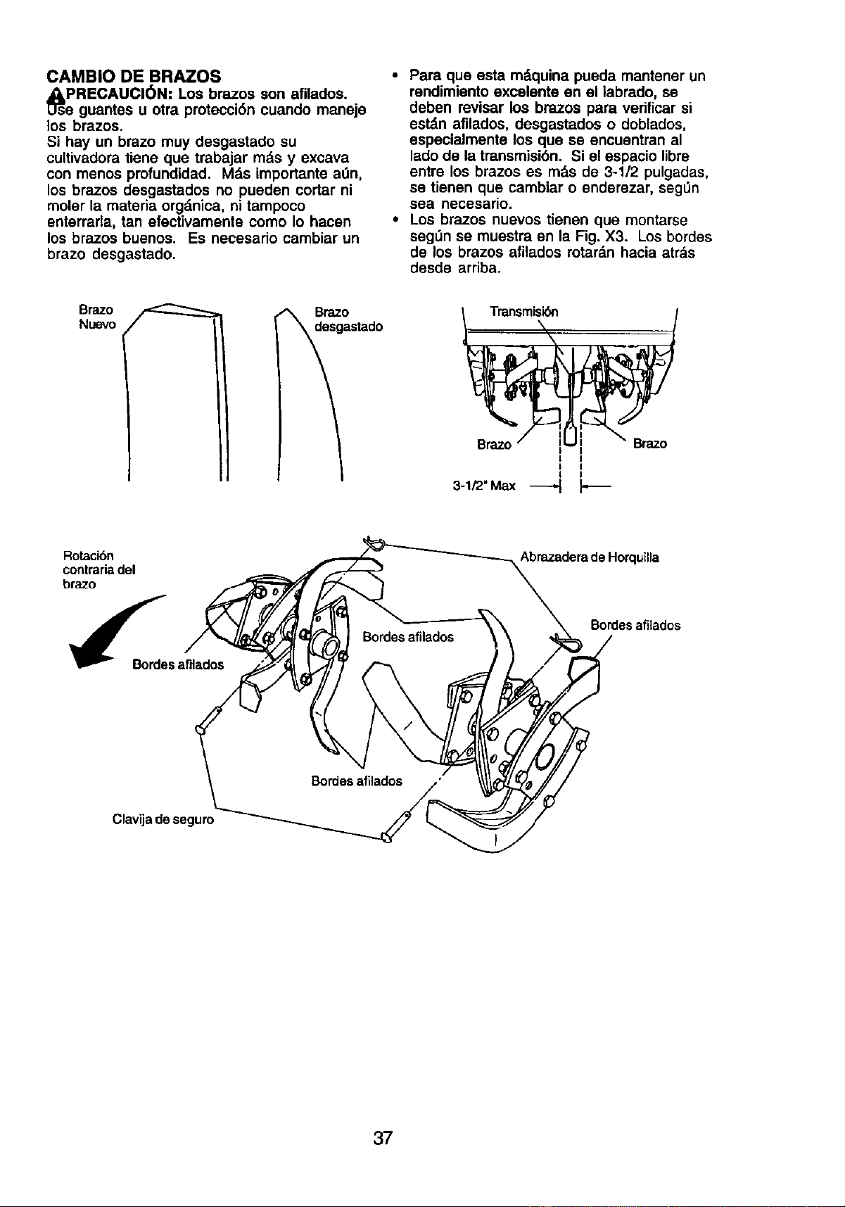
CAMBIO DE BRAZOS
_sPRECAUCI6N: Los brazos afilados.
son
e guantes u otra protecci6n cuando maneje
los brazos.
Si hay un brazo muy desgastado su
cultivadora tiene que trabajar rods y excava
con menos profundidad. M_.simportante alan,
los brazos desgastados no pueden cortar ni
moler la mateda orgdnica, ni tampoco
enterrarla, tan efectivamente como Io hacen
los brazos buenos. Es necesado cambiar un
brazo desgastado.
• Para que esta mdquina pueda mantener un
rendimiento excelente en el labrado, se
deben revisar los brazos para verificar si
estdn afllados, desgastados o doblados,
especialmente los que se encuentran al
ladode la transmisi6n. Si el espacio libre
entre los brazos es rods de 3-1/2 pulgadas,
se tienen que cambiar o enderezar, seg_n
sea necesario.
• Los brazos nuevos tienen que montarse
seg_n se muestra en la Fig. X3. Los bordes
de los brazos afilados rotardn hacia atr_.s
desde arriba.
B zo
Nuevo
es_°astado
I I
I I
I I
I I
3-1/2' Max _-_
Rotacibn
contrariadel
brazo
Abrazadera de Horquilla
Bordes afilados
Clavijade seguro
37
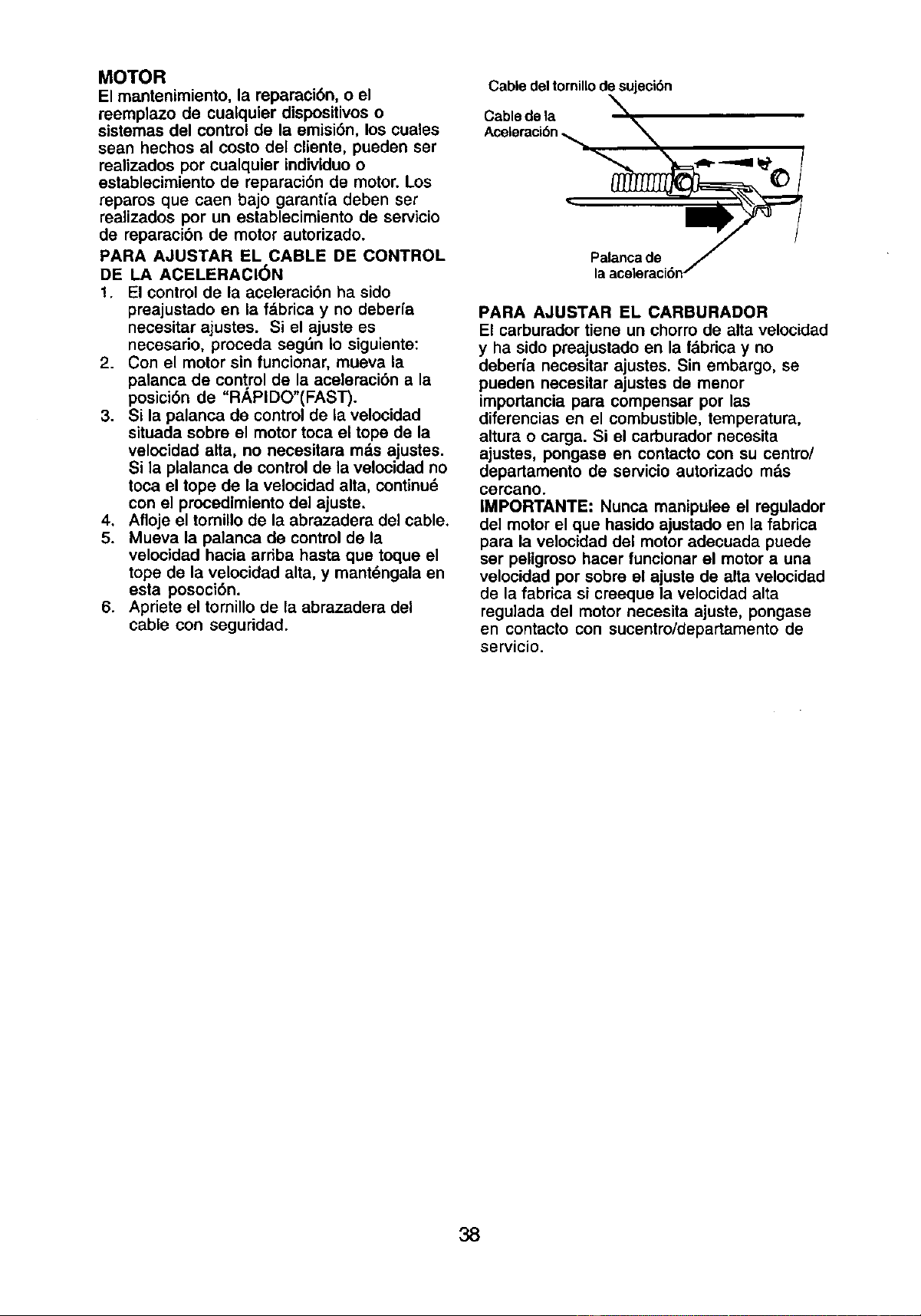
MOTOR
El mantenimiento, la reparaci6n, o el
reemplazo de cualquier dispositivoso
sistemas del control de la emisi6n, los cuales
sean hechos al costo del cliente, pueden ser
realizados por cualquier indMduo o
establecimiento de reparaci6n de motor. Los
reparos que caen bajo garantfa deben ser
realizados por un establecimiento de servicio
de reparacibn de motor autorizado.
PARA AJUSTAR EL CABLE DE CONTROL
DE LA ACELERACI(_N
1. El controlde la aceleraci6n ha sido
preajustado en la fdbrica y no deberfa
necesitar ajustes. Si el ajuste es
necesario, proceda segdn Io siguiente:
2. Con el motor sin funcionar, mueva la
palanca de control de la aceleraci6n a la
posici6n de "RAPIDO"(FAST).
3. Si la palanca de control de la velocidad
situada sobre el motor toca el tope de la
velocidad alta, no necesitara md.sajustes.
Si la plalanca de control de la velocidad no
toca el tope de la velocidad alta, continu_
con el procedimiento del ajuste.
4, Afloje el tomillo de la abrazadera del cable.
5. Mueva la palanca de control de la
velocidad hacia arriba hasta que toque el
tope de la velocidad alta, y mant_ngala en
esta posoci6n.
6. Apdete el tomillo de la abrazadera del
cable con seguridad.
Cabledeltomillodesujeck:_n
Cablede la
Aceleracibn_ N
-
"
PARA AJUSTAR EL CARBURADOR
El carburador tiene un chorro de alta velocidad
y ha sido preajustado en la fdbdca y no
deber[a necesitar ajustes. Sin embargo, se
pueden necesitar ajustes de menor
importancia para compensar por las
diferencias en el combustible, temperatura,
altura o carga. Si el carburador necesita
ajustes, pongase en contacto con su centre/
departamento de servicio autorizado m&s
cercano.
IMPORTANTE: Nunca manipulee el regulador
del motor el que hasido ajustado en la fabrica
para la velocidad del motor adecuada puede
ser peligroso hacer funcionar el motor a una
velocidad por sobro el ajuste de alta velocidad
de la fabrica si creeque la velocidad alta
regulada del motor necesita ajuste, pongase
en contacto con sucentro/departamento de
servicio.
38
Inmediatamente prepare su cultivadore pare el
almacenamiento al final de la temporada o si la
unidad no se va a usar pot 30 dfas o m&s.
,I_PRECAUCI(_N: Nunca almacene la
cultivadore con gasolina en el estanque dentro
de un edificio en donde los gases pueden
alcanzar una llama expuesta o una chispa.
Permita que el motor se enfrie antes de
almacenado en cualquier recinto privado.
CULTIVADORA
1. Limpie toda la cultivadora (vea "LIMPIEZA"
en la secci6n de Mantenimiento en este
manual).
2. Inspeccione y cambie las correas, si es
necesario (vea las instrucciones para el
cambio de la correa en la seccibn de
Servicio y Ajustes de este manual).
3. Lubffquela segt_nse muestra en la
secci6n de Mantenimiento en este manual.
4. AsegOrese que todas las tuercas, pernos
y tornillos est_n apretados en forma
segura. Inspeccione las partes movibles
para verificar si est&n daSadas, rotas o
desgastadas. C_mbielas si es necesario.
5. Retoque todas las superficies pintadas
que est_n oxidadas o picadas; use una lija
suavemente antes de pintar.
MOTOR
SISTEMA DE COMBUSTIBLE
IMPORTANTE: Es importante evitar que se
formen dep6sitos de goma en partes
fundamentales del sistema de combustible
tales como el carburador, el filtro del combus-
tible, la manguere del combustible o en el
estanque durante el almacenamiento. La
experiencia tambi_n indica que los combus-
tibles mezclados con alcohol (conocido come
gasohol o que tienen etanol o metanol) pueden
atraer humedad, Io que conduce a la
separaci6n de _.cidos durante el
almacenamiento. La gasolina _cidica puede
daSar el sistema de combustible de un motor
durante el periodo de almacenamiento.
1. Drene el estanque de combustible.
2. Haga arrancar el motor y d6jelo funcionar
hasta que las I_neas del combustible y el
carburador estdn vaclos.
• Nunca use los productos para limpieza del
carburador o del motor en el estanque de
combustible pues se pueden producir
da_os permanentes.
• Use combustible nuevo la pr6xima
temporada.
AVISO: El estabilizador de combustible es una
altemativa aceptable para reducir a un m_nimo
la formaci6n de dep6sitos de goma en el
combustible durante el perfodo de
almacenamiento. Agregue estabilizador a la
gasolina en el estanque de combustible o en el
envase para el almacenamiento. Siempre siga
la propomi6n de mezcla que se encuentre en
el envase del estabilizador. Haga funcionar el
motor por Io menos 10 minutos despu_s de
agregar el estabilizador, para permitir que _)ste
Ilegue al carburador. No drene la gasolina del
estanque de gasolina y el carburador si se
est,. usando estabilizador de combustible.
ACEITE DEL MOTOR
Drene el aceite (con el motor caliente) y
c&mbielocon aceite de motor limpio. (Vea
"MOTOR" en la secci6n de Mantenimiento de
este manual.)
CILINDRO(S)
1. Remueva la bujfa.
2. Vacfe una onza de aceite a trev_s del
agujero de la bujfa en el cilindro.
3. Tire el mango del arrencador, lentamente,
varias veces para distdbuir el aceite.
4. Cambie por una bujfa nueva.
OTROS
• No guarde la gasolina de una temporada a
la otra.
• Cambie el envase de la gasolina si se
empieza a oxidar. La oxidaci6n y/o la mugre
en su gasolina producir_.npreblemas.
• Si es posible, guarde su unidad en un
recinto cerrado y clJbrala pare protegerla
contre el polvo y la mugre.
• Cubra su unidad con un forro protector
adecuado que no retenga la humedad. No
use pl&stico.El pl&sticono puede respirar,
Io que permite la formaci6n de
condensaci6n, Io que producir&la oxidaci6n
de su unidad.
IMPORTANTE: Nunca cubra la cultivadore
mientres el motor y las areas de escape
todavia estan calientes.
39
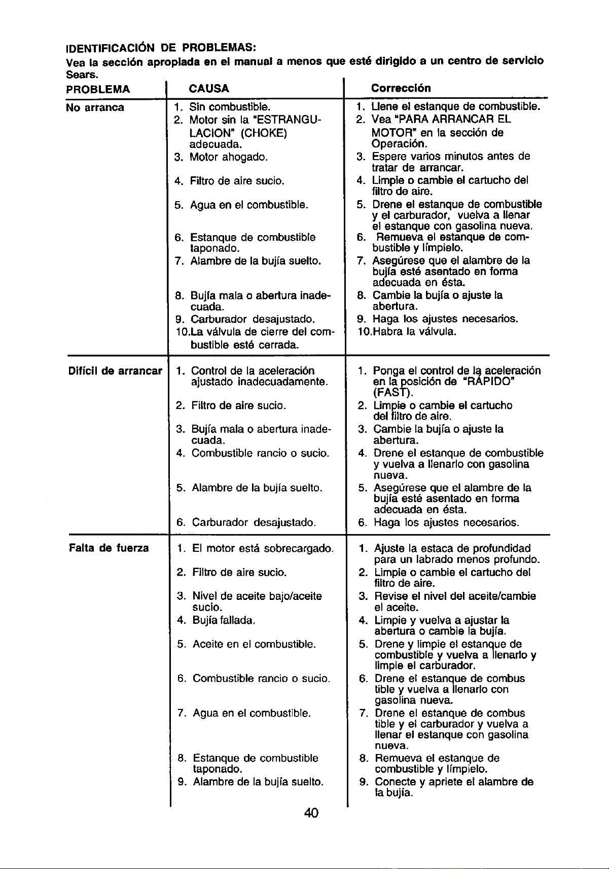
IDENTIFICACI(_N DE PROBLEMAS:
Vea la seccl6n aproplade en el manual a menos que estd
Sears.
PROBLEMA CAUSA
1. Sin combustible.
2. Motor sin la =ESTRANGU-
LACION" (CHOKE)
adecuada.
3. Motor ahogado.
4.
5.
No arranca
Diflcil de arrancar
Falta de fuerza
dirigido a un centro de servlclo
Filtro de airs sucio.
Agua en el combustible.
6. Estanque de combustible
taponado.
7. Alambre de la bujfa suelto.
8. Bujfa mala o abertura inade-
cuada.
9. Carburador desajustado.
10.La vdlvula de cierre del com-
bustible est6 cerrada.
1. Control de la aceleraci6n
ajustado inadecuadamente.
2. Filtro de aire sucio.
3. Bujfa mala o abertura inade-
cuada.
4. Combustible rancio o sucio.
5. Alambre de la bujia suelto.
6. Carburador desajustado.
1. El motor estd sobrecargado.
2. Filtro de airs sucio.
3. Nivel de aceite bajo/aceite
sucio.
4. Bujia fallada.
5. Aceite en el combustible.
6. Combustible rancio o sucio.
7. Agua en el combustible.
8. Estanque de combustible
taponado.
9. Alambre de la bujfa suelto.
Correccl6n
1. Llene el estanque de combustible.
2. Yea "PARA ARRANCAR EL
MOTOR" en la secci6n de
Operaci6n.
3. Espere vados minutos antes de
tratar de arrancar.
4. Umpie o cambie el eartucho del
filtro de airo.
5. Drone el estanque de combustible
y el carburador, vuelva a Ilenar
el estanque con gasolina nueva.
6. Remueva el estanque de com-
bustible y Ifmpielo.
7. Aseg_rose que el alambre de la
bujfa est6 asentado en forma
adecuada en 6sta.
8. Cambie la bujl'a o ajuste la
abertura.
9. Haga los ajustes necesados.
10.Habra la vdlvula.
1. Ponga el control de I_ aceleraci6n
en la posici6n de =RAPIDO"
(FAST).
2. Limpie o cambie el cartucho
del filtro de airs.
3. Cambie la bujfa o ajuste la
abertura.
4. Drene el estanque de combustible
y vuelva a IIenarlo con gasolina
nueva.
5. Aseg0rese que el alambre de la
bujia est_ asentado en forma
adecuada en dsta.
6. Haga los ajustes necesarios.
1. Ajuste la estaca de profundidad
para un labrado menos pro|undo.
2. Limpie o cambie el cartucho del
filtro de aire.
3. Revise el nivel del aceite/cambie
el ace|re.
4. Limpis y vuelva a ajustar la
abertura o cambie la bujfa.
5. Drone y limpie el estanque de
combustible y vuelva a/lenado y
limpie el carburador.
6. Drene el estanque de combus
tible y.vuelva a Ilenarlo con
gaso==nanueva.
7. Drene el estanque de combus
tible y el carburador y vuelva a
Ilenar el estanque con gasolina
nueva.
8. Remueva el estanque de
combustible y Ifmpielo.
9. Conecte y apriete el alambre de
la bujfa.
40
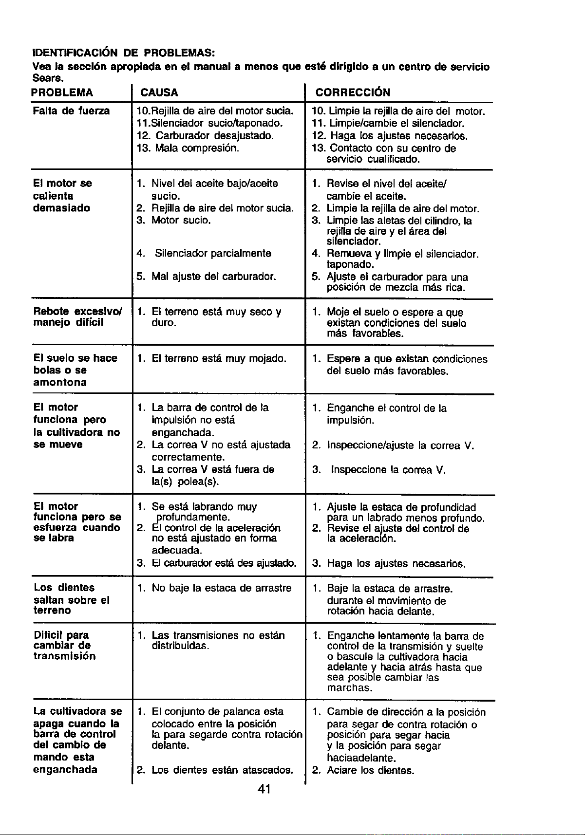
IDENTIFICACI6N DE PROBLEMAS:
Vea le seccl6n aproplada en el manual a menos que est6 dirlgldo a un centro de servicio
Sears.
PROBLEMA
Falta de fuerza
El motor se
calienta
demasiado
CAUSA
10.Rejilla de aire del motor sucia.
11.Silenciador sucio/taponado.
12. Carburador desajustado.
13. Mala compresi6n.
1. Nivel del aceite bajo/aceite
sucio.
2. Rejilla de aire del motor sucia.
3. Motor sucio,
4. Silenciador parcialmente
5. Mal ajuste del carburador.
CORRECCION
10. Limpie la rejilla de aire del motor.
11. Limpie/cambie el silenciador.
12. Haga los ajustes necesarios.
13. Contacto con su centro de
servicio cualificado.
1. Revise el niveldel aceite/
cambie el aceite.
2. Limpie la rejilla de aire del motor.
3. Limpie las aletas del cilindro,la
rejilla de aire y el drea del
silenciador.
4. Remueva y limpie el silenciador.
taponado.
5. Ajuste el carburador para una
posici6n de mezcla mds dca.
Rebote exceslvo/ 1. El terreno est,1muy seco y 1. Moje el suelo o espem a que
manejo diffcil duro. existan condiciones del suelo
mds favorables.
El suelo se hace 1. El terreno est_ muy mojado. 1. Espere a qua existan condiciones
bolas o se del suelo mds favorables.
amontona
El motor
funciona pero
la cultivadora no
se mueve
El motor
funclona pero se
esfuerza cuando
se labra
1. La barra de control de la
impulsi6n no est,,
enganchada.
2, La correa V no estd ajustada
correctamente.
3. La correa V estd fuera de
la(s) polea(s).
1. Se est& labrando muy
profundamente,
2. El control de la aceleraci6n
no estd ajustado en forma
adecuada.
3. El carburadorestd des ajustado.
1. No baje la estaca de arrastre
1. Las transmisiones no estdn
distribuidas.
1. El conjunto de palanca esta
colocado entre la posici6n
la para segarde contra mtaci6n
delante.
2. Los dientes estdn atascados.
Los dientes
saltan sobre el
terreno
Diflcll para
cambiar de
transmisi6n
La cultivadora se
apaga cuando la
barra de control
del cambio de
mando esta
enganchada
1. Enganche el control de la
impulsi6n.
2. Inspeccione/ajuste la correa V.
3. Inspeccione la correa V.
1. Ajuste la estaca de profundidad
para un labrado menos profundo.
2. Revise el ajuste del controlde
la aceleraci6n.
3. Haga los ajustes necesarios.
1. Baje la estaca de arrastra.
durante el movimiento de
rotaci6n hacia delante.
1,
Enganche lentamente la barra de
controlde la transmisibn y suelte
o bascule la cultivadora hacia
adelante y hacia atrds hasta que
sea posible cambiar las
marchas.
1. Cambie de direcci6n a la posici6n
para segar de contra rotaci6n o
posici6n para segar hacia
y la posicibn para segar
haciaadelante.
2. Aciare los dientes.
41
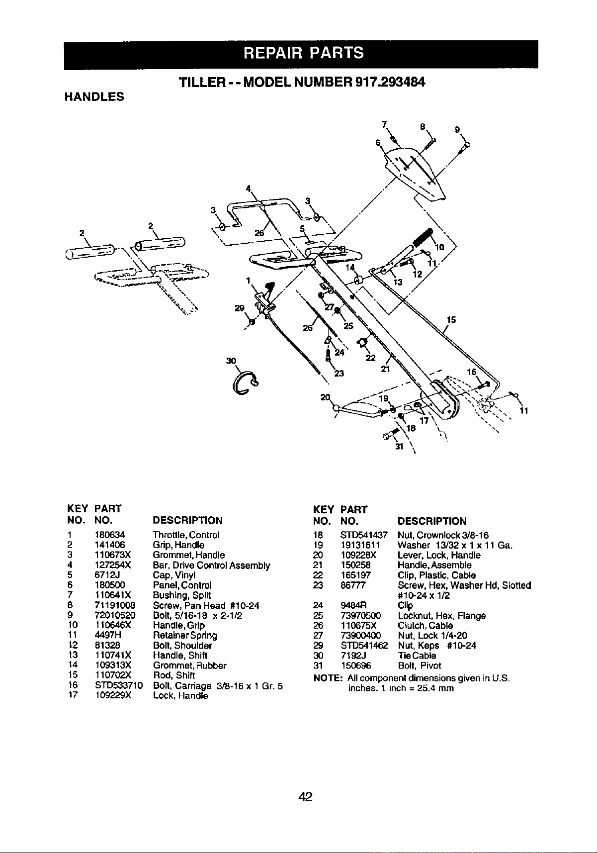
TILLER -- MODEL NUMBER 917.293484
HANDLES
3
2
3
15
31 \\
11
KEY PART
NO. NO,
1 180634
2 141406
3 110673X
4 127254X
5 6712J
6 18O5OO
7 110641X
8 71191008
9 72010520
10 110646X
11 4497H
12 81328
13 110741X
14 109313X
15 110702X
16 STD533710
17 109229X
DESCRIPTION
Throttle, Control
Grip.Handle
Grommet,Handle
Bar, Drive ControlAssembly
Cap, Vinyl
Panel, Control
Bushing, Split
Screw, Pan Head #10-24
Bolt, 5/16-18 x 2-1/2
Handle, Grip
RetainerSpring
Bolt, Shoulder
Handle, Shift
Grommet, Rubber
Rod, Shift
Bolt, Cardage 3/8-16 x 1 Gr. 5
Lock, Handle
KEY PART
NO. NO. DESCRIPTION
18 STD541437 Nut, Crowniock 3/8-16
19 19131611 Washer 13/32 x 1 x 11 Ga.
20 109228X Lever, Lock, Handle
21 150258 Handle,Assemble
22 165197 Clip, Plastic.Cable
23 86777 Screw, Hex, Washer Hd, Slotted
#10-24 x 1/2
24 9484R Ctip
25 73970500 Locknut,Hex, Flange
26 110675X Clutch, Cable
27 73900400 Nut, Lock 1/4-20
29 STD541462. Nut, Keps #10-24
30 7192J Tie Cable
31 150696 Bolt, Pivot
NOTE: Allcomponentdimensionsgivenin U.S.
inches. 1 inch = 25.4 mm
42
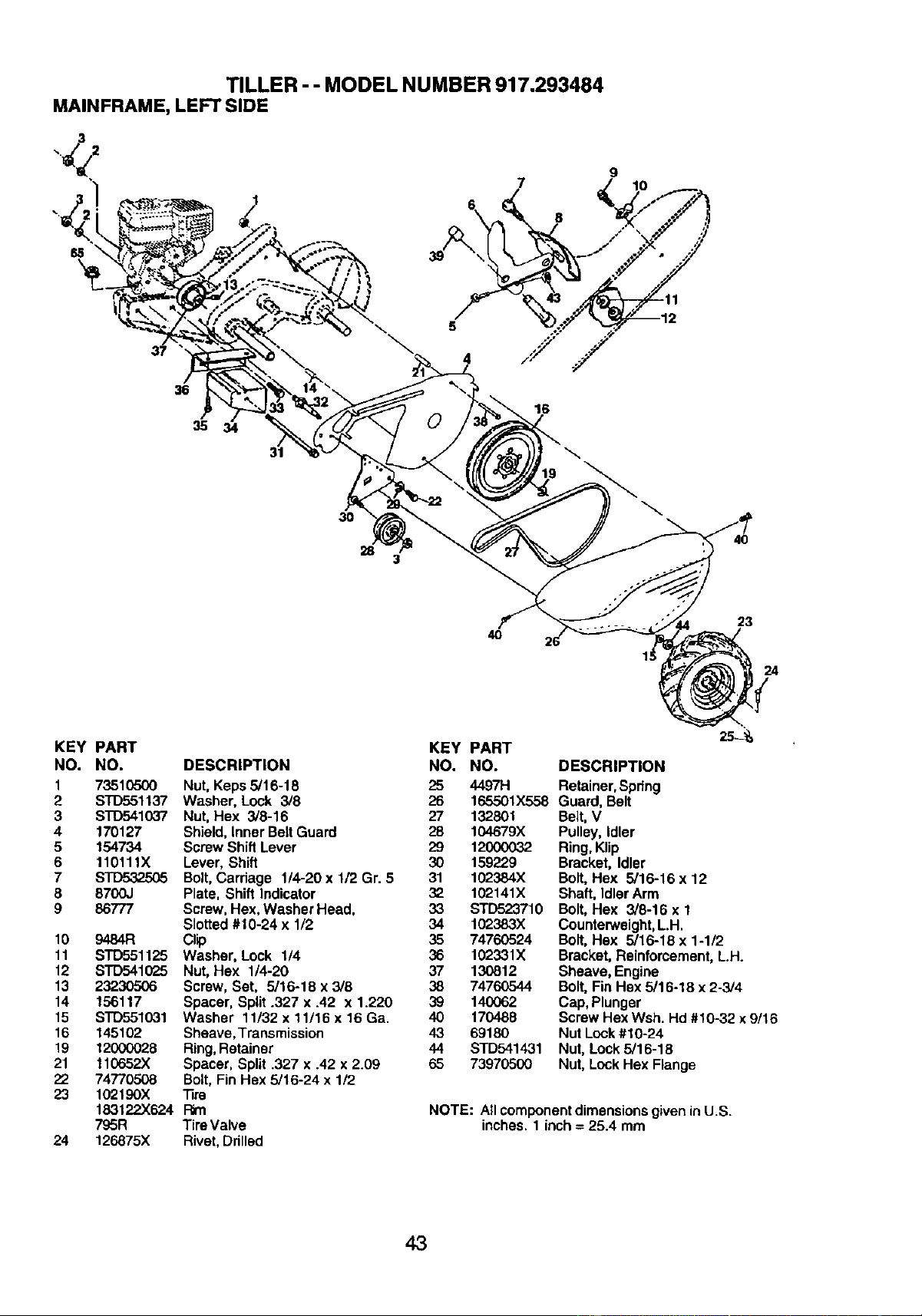
TILLER - - MODEL NUMBER 917.293484
MAINFRAME, LEFT SIDE
7
5
4 /"_"
9
8
36
35
16
3O
28
3
\
40
23
24
KEY PART
NO. NO.
1 73510500
2 S'rD551137
3 S'rD541037
4 170127
5 154734
6 110111X
7 STD532505
8 8700J
9 86777
10 9484R
11 STD551125
12 STD541025
13 23230506
14 156117
15 S'rD551031
16 145102
19 12000028
21 110652X
22 74770508
23 102190X
183122X624
7O_5R
24 126875X
KEY
DESCRIPTION NO,
Nut, Keps 5/16-18 25
Washer, Lock 3/8 26
Nut, Hex 3/8-16 27 132801
Shield, Inner BeltGuard 28 104679X
Screw Shift Lever 29 12000032
Lever, Shift 30 159229
Bolt, Cardage 1/4-20 x 1/2 Gr. 5 31 102384X
Plate, Shift Indicator 32 102141X
Screw, Hex, Washer Head, 33 STD523710
Slotted #10-24 x 1/2 34 102383X
Clip 35 74760524
Washer, Lock 1/4 36 102331X
Nut, Hex 1/4-20 37 130812
Screw, Set, 5/16-18 x 3/8 38 74760544
Spacer, Split .327 x .42 x 1.220 39 140062
Washer 11/32 x 11/16 x 16 Ga. 40 170488
Sheave,Transmission 43 69180
Ring, Retainer 44 STD541431
Spacer, Split .327 x .42 x 2.09 65 73970500
Bolt,Fin Hex 5/16-24 x 112
"13re
Rm
Tim Valve
Rivet,Ddlled
PART
NO. DESCRIPTION
4497H Retainer,Spnng
165501X558Guard,Belt
2S-_
Belt, V
Pulley, Idler
Ring,Klip
Bracket, Idler
Bolt,Hex 5/16-16 x 12
Shaft, Idler Arm
Bolt,Hex 3/8-16 x 1
Counterweight,L.H.
Bolt,Hex 5/16-18 x 1-1/2
Bracket, Rsinfomement, LH.
Sheave, Engine
Bolt,Fin Hsx 5/16-18 x 2-3/4
Cap, Plunger
Screw Hex Wsh. Hd #10-32 x 9/16
Nut Lock#10-24
Nut, Lock 5/16-18
Nut, Lock Hex Flange
NOTE: Allcomponentdimensionsgiven inU.S.
inches. 1 inch = 25.4 mm
43
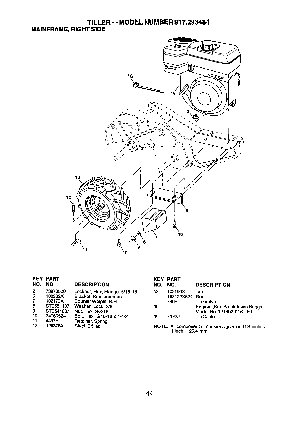
TILLER -- MODEL NUMBER 917.293484
MAINFRAME, RIGHT SIDE
16
12
13
i
11 9
lO
KEY PART
NO. NO. DESCRIPTION
2 73970500 Locknut, Hex, Flange 5/16-18
5 102332X Bracket, Reinforcement
7 102173)( CounterWeight, R.H.
8 STD551137 Washer, Lock 3/8
9 STD541037 Nut, Hex 3/8-16
10 74760524 Bolt,Hex 5/16-18 x 1-1/2
11 4497H Retainer,Spdng
12 126875X Rivet, Drilled
KEY PART
NO. NO. DESCRIPTION
13 10_190X Tim
183122X624 Pkn
795R Tire Valve
15 Engine,(See Breakdown) Briggs
Model No.121402-0161-E1
16 71923 TieCable
NOTE: All componentdimensions giveninU.S.inches.
1 inch = 25.4 mm
44
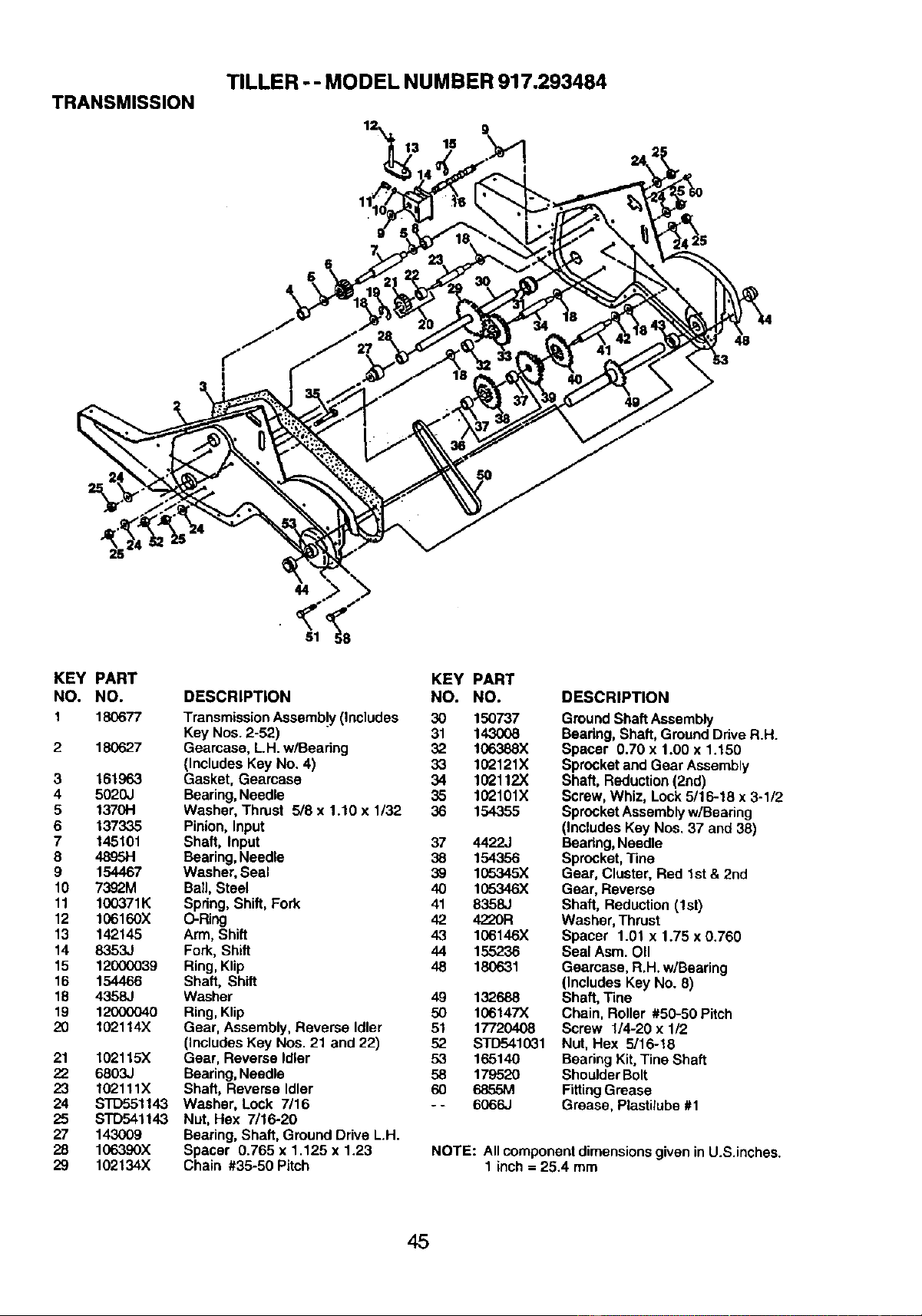
TRANSMISSION
TILLER -- MODEL NUMBER 917.293484
11
44
81
KEY PART
NO. NO.
1 180677
2 180627
3 161963
4 5020J
5 1370H
6 137335
7 145101
8 4895H
9 154467
10 7392M
11 100371K
12 106160X
13 142145
14 8353,.I
15 12000039
16 154466
18 4358J
19 12000040
20 102114X
21 102115X
22 6803J
23 102111X
24 STD551143
25 STD541143
27 143(X)9
28 106390X
29 102134X
KEY PART
DESCRIPTION NO. NO.
Transmission Assemb!y(Includes 30 150737
Key Nos. 2-52) 31 143008
Gearcase, LH. w/Bearing 32 106388X
(Includes Key No, 4) 33 102121X
Gasket, Gearcase 34 102112X
Bearing,Needle 35 102101X
Washer, Thrust 5/8 x 1.10 x 1/32 36 154355
Pinion, Input
Shaft, Input 37 44_J
Bearing, Needle 38 154356
Washer, Seal 39 105345X
Bail, Steel 40 105346X
Spring, Shift, Fork 41 8358J
O-Ring 42 4220R
Arm, Shift 43 106146X
Fork, Shift 44 155236
Ring, Klip 48 180631
Shaft, Shift
Washer 49 132688
Ring, Klip 50 106147X
Gear, Assembly, Reverse Idler 51 17720408
(Includes Key Nos. 21 and 22) 52 STD541031
Gear, Reverse Idler 53 165140
Bearing,Needle 58 179520
Shaft, Reverse Idler 60 6855M
Washer, Lock 7/16 - - 6066,,I
Nut, Hex 7/16-20
Bearing, Shaft, Ground Drive L.H.
Spacer 0.765 x 1.125 x 1.23
Chain #35-50 Pitch
DESCRIPTION
GroundShaft Assembly
Beadng, Shaft, GroundDrive R.H.
Spacer 0.70 x 1.00 x 1.150
Sprocketand Gear Assembly
Shaft, Reduction(2nd)
Screw, Whiz, Lock5/16-18 x 3-1/2
SprocketAssembly w/Bearing
(Includes Key Nos, 37 and 38)
Bearing, Needle
Sprocket, "line
Gear, Cluster, Red 1st & 2nd
Gear, Reverse
Shaft, Reduction (1st)
Washer, Thrust
Spacer 1.01 x 1.75 x 0.760
Seal Asm. OII
Gearcase, R.H. w/Bearing
(Includes Key No. 8)
Shaft, "line
Chain, Roller #50-50 Pitch
Screw 1/4-20 x 1/2
Nut, Hex 5/16-18
Bearing Kit, Tine Shaft
Shoulder Bolt
Fitting Grease
Grease, Plastilube #1
NOTE: Allcomponentdimensionsgiven in U.S.inches.
1 inch = 25.4 mm
45
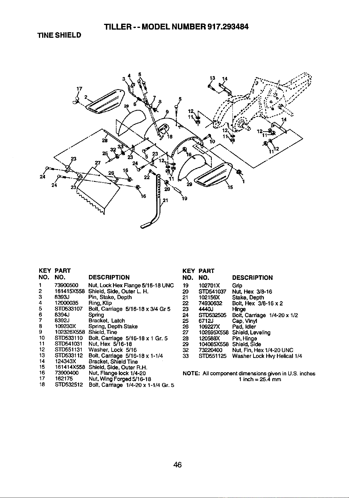
TILLER -- MODEL NUMBER 917.293484
TINE SHIELD
24
17
5
3 13
5
19
14
1
15
KEY PART
NO. NO.
1 739(X}5(X)
2 161415X558
3 8393J
4 12000035
5 STD533107
6 8394J
7 8392J
8 1G9230X
9 102326X558
10 STD533110
11 STD541031
12 STD551131
13 s'rD533112
14 124343X
15 161414X558
16 73900400
17 162175
18 STD532512
DESCRIPTION
Nut, Lock Hex Flange 5/16-18 UNC
Shield, Side, Outer L. H.
Pin, Stake, Depth
Ring, Klip
Bolt, Carriage 5/16-18 x 3/4 Gr 5
Spring
Bracket, Latch
Spring, Depth Stake
Shield, "line
Bolt,Carriage 5/16-18 x 1 Gr. 5
Nut, Hex 5/16-18
Washer, Lock 5/16
Bolt,Carriage 5/16-18 x 1-1/4
Bracket, Shield Tine
Shield, Side, Outer R.H.
Nut, Flange lock 1/4-20
Nut, Wing Forged5/16-18
Bolt, Carriage 1/4-20 x 1-1/4 Gr. 5
KEY PART
NO. NO. DESCRIPTION
19 102701X Grip
20 STD541037 Nut, Hex 3/8-16
21 102156X Stake, Depth
22 74930632 Bolt, Hex 3/8-16 x 2
23 444OJ Hinge
24 STD_"_505 Bolt,Carriage 1/4-20 x 1/2
25 6712J Cap, Vinyl
26 109227X Pad, Idler
27 102695X558 Shield, Leveling
28 120588X Pin, Hinge
29 104085X558 Shield, Side
32 73220400 Nut, Fin, Hex 1/4-20 UNC
33 S'1"D551125 Washer LockHvy Helical 1/4
NOTE: All componentdimensionsgivenin U.S. inches
I inch = 25.4 mm
46
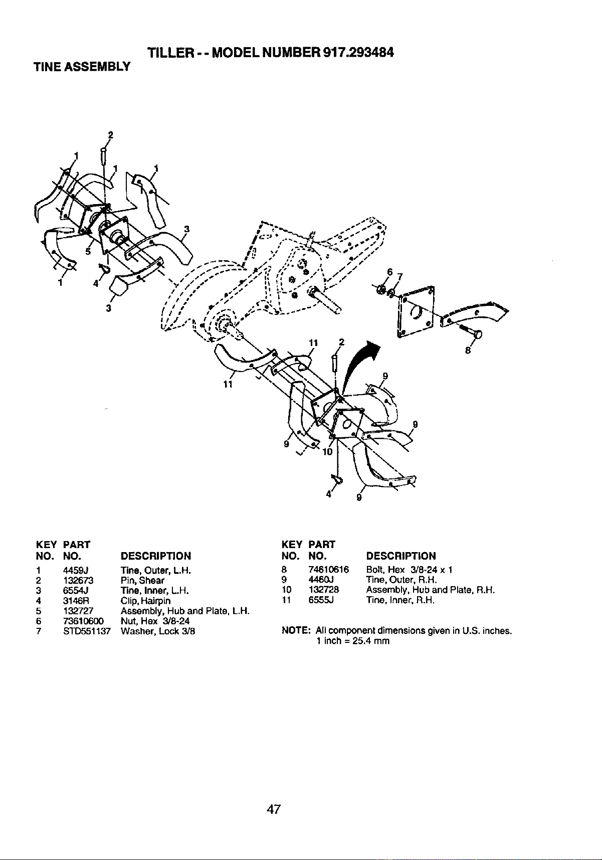
TILLER - - MODEL NUMBER 917.293484
TINE ASSEMBLY
2
1
1
3
KEY PART
NO. NO. DESCRIPTION
1 4459J Tine, Outer, L.H.
2 132673 Pin,Shear
3 6554J Tine, Inner, L.H.
4 3146R Clip,Hairpin
5 132727 Assembly, Hub and Plate, L.H.
6 73610600 Nut, Hex 3/8-24
7 STD551137 Washer, Lock 3/8
KEY PART
NO. NO. DESCRIPTION
B 74610616 Bolt, Hex 3/8-24 x 1
9 4460J Tine, Outer, R.H.
10 132728 Assembly, Huband Plate, R.H.
11 6555J Tino, Inner, R.H.
NOTE: All componentdimensionsgiven inU.S. inches.
1 inch = 25.4 mm
47
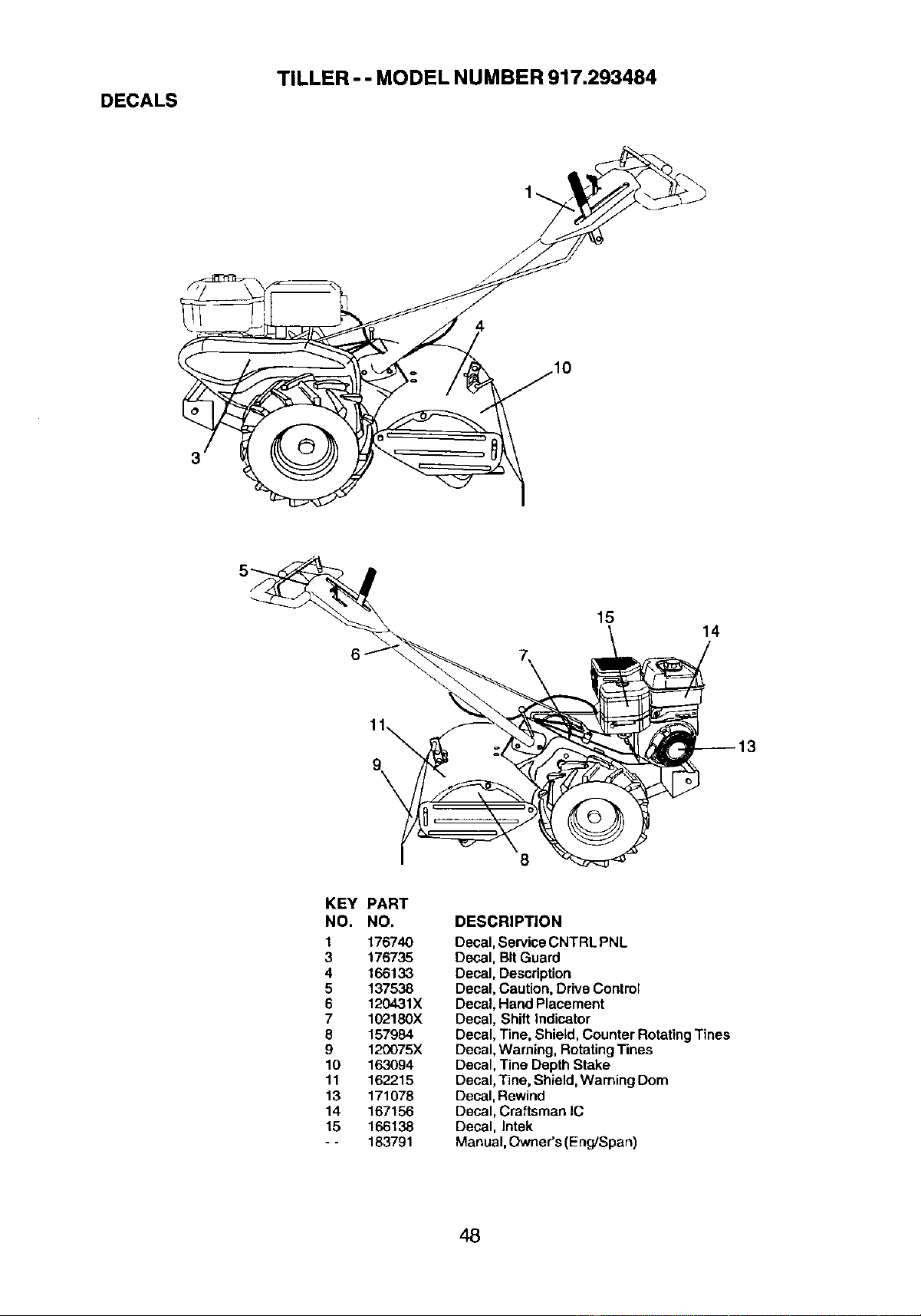
TILLER - - MODEL NUMBER 917.293484
DECALS
15
14
8
KEY PART
NO. NO.
1 176740
3 176735
4 166133
5 137538
6 120431X
7 102180X
8 157984
9 120075X
10 163094
11 162215
19 171078
14 167156
15 166138
-- 183791
DESCRIPTION
Decal, ServiceCNTRL PNL
Decal, BitGuard
Decal, Description
Decal, Caution, DriveControl
Decal, Hand Placement
Decal, Shift Indicator
Decal, Tine, Shield, Counter RotatingTines
Decal, Warning, RotatingTines
Decal, Tine Depth Stake
Decal, Tine, Shield,Warning Dom
Decal, Rewind
Decal, Craftsman IC
Decal, Intek
Manual, Owner's (Eng/Span)
48
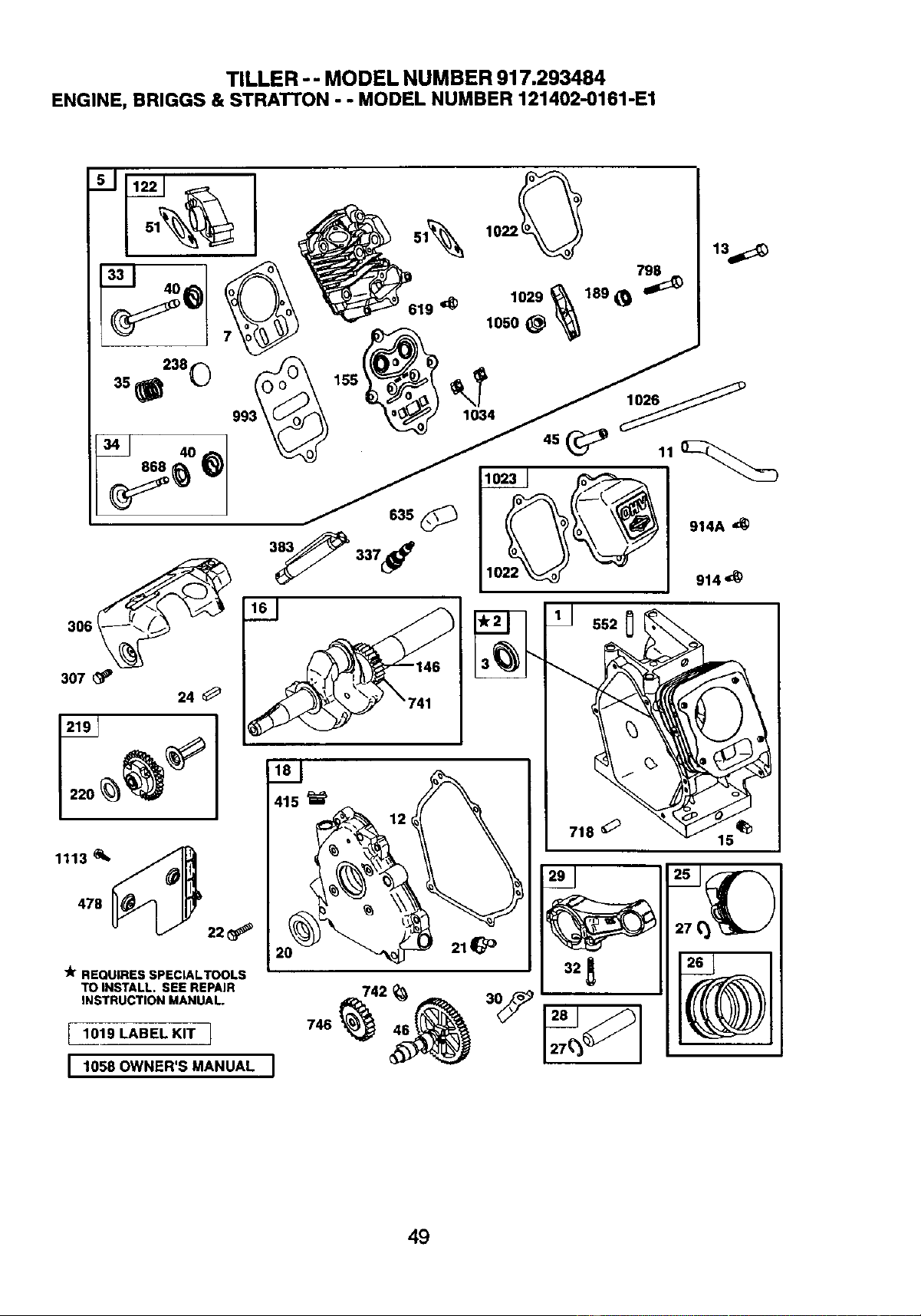
TILLER - - MODEL NUMBER 917.293484
ENGINE, BRIGGS & STRATTON - - MODEL NUMBER 121402-0161-E1
307
24
"k REQUIRES SPECIALTOOLS
TO INSTALL. SEE REPAIR
INSTRUCTION MANUAL
I 1019 LABEL KIT 1
1058 OWNER'S MANUAL
619 _
1_ 552 0
718 _
15
=70j_k.,-J
49
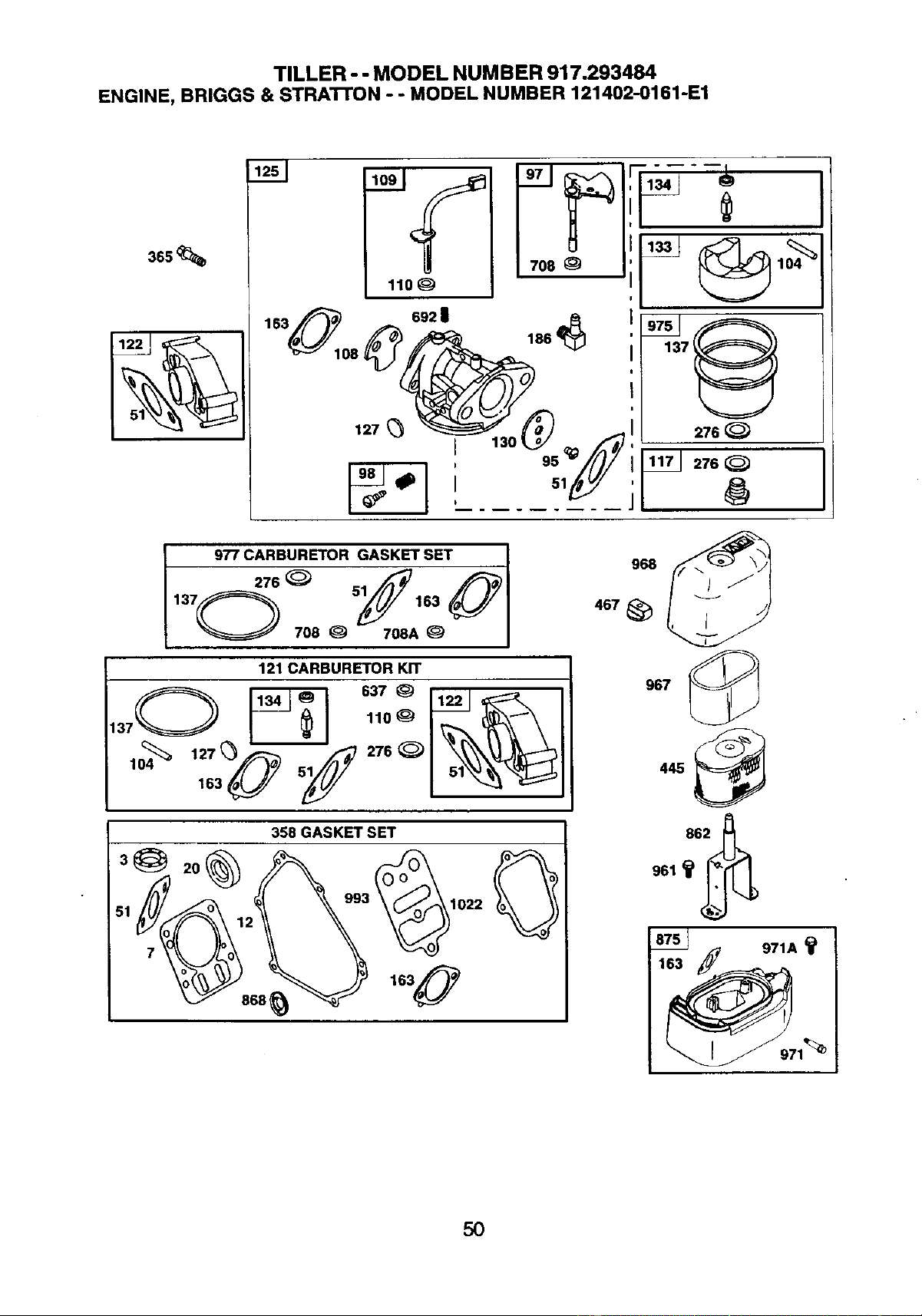
TILLER - - MODEL NUMBER 917.293484
ENGINE, BRIGGS & STRA'i-I'ON o - MODEL NUMBER 121402-0161-E1
3ss_,
692 |
127
186
I !
276
17J 276
977 CARBURETOR GASKET SET
I
137 276 _ 51 163
O 7O8 _ 708A _ I
121 CARBURE_rOR KIT
358 GASKET SET
968
467_
967
961 _
971A
1
5O
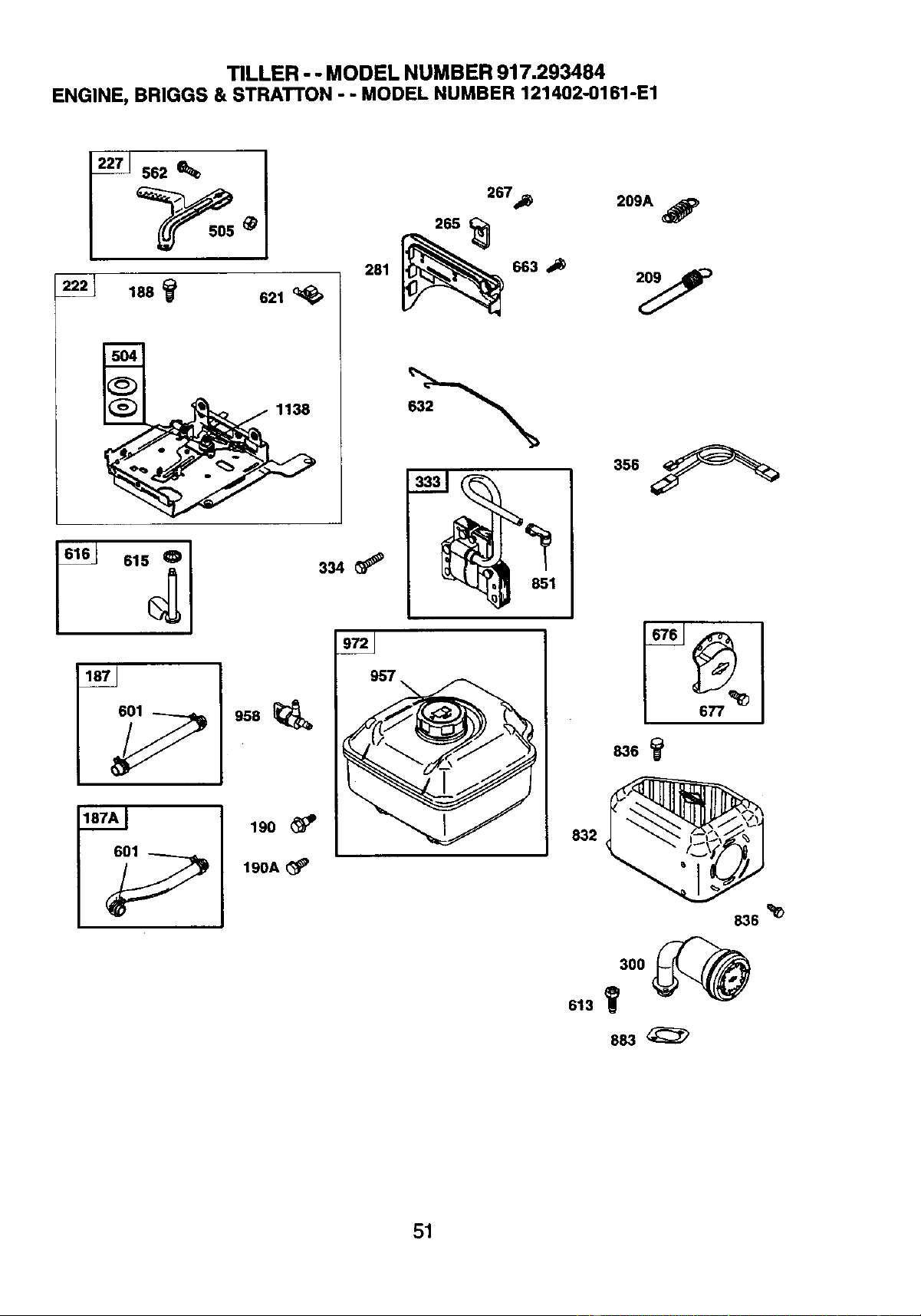
TILLER - - MODEL NUMBER 917.293484
ENGINE, BRIGGS & STRATTON - - MODEL NUMBER 121402-0161-E1
188
615 0
621
267_
281 _ 663
187A_ 190
190A_
209A _p
832
836 _
51
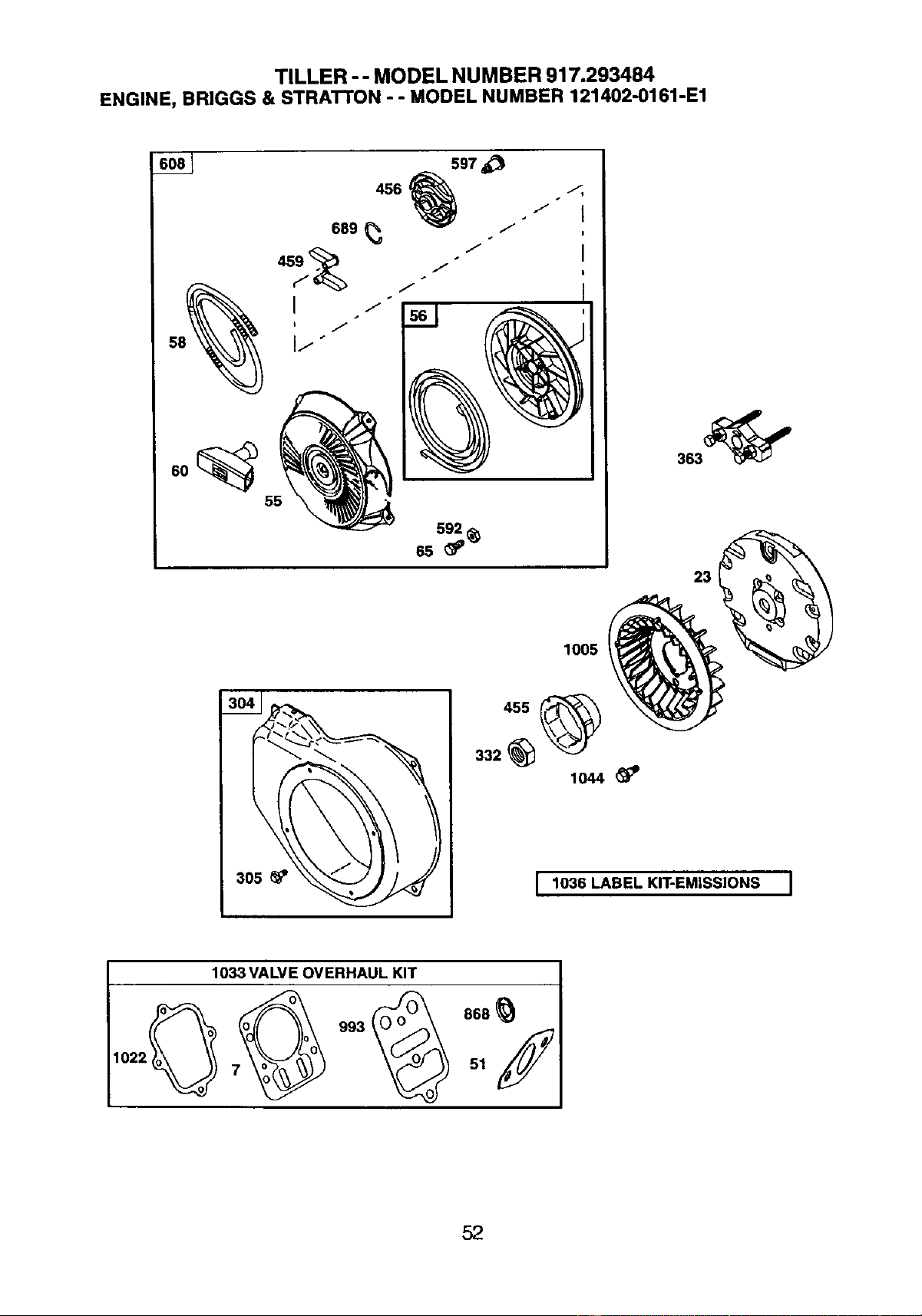
TILLER -- MODEL NUMBER 917.293484
ENGINE, BRIGGS & STRATTON - - MODEL NUMBER 121402-0161-E1
o5_ _
305
1005
455
332
1044
I 1036 LABEL KIT-EMISSIONS I
1033 VALVE OVERHAUL KIT
1022 51
52
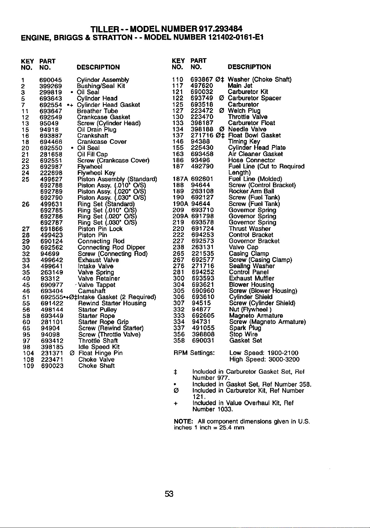
TILLER - - MODEL NUMBER 917.293484
ENGINE, BRIGGS & STRATrON - - MODEL NUMBER 121402-0161-E1
KEY PART KEY PART
NO. NO. DESCRIPTION NO. NO. DESCRIPTION
1
2
3
5
7
11
12
13
15
16
18
20
21
22
23
24
25
26
27
28
29
30
32
33
34
35
40
45
46
51
55
56
58
60
65
95
97
98
104
108
109
690045 Cylinder Assembly 110 693867 _:1: Washer (Choke Shaft)
399269 Bushing/Seal Kit 117 497620 Main Jet
299819 • Oil Seal 121 690032 Carburetor Kit
693643 Cylinder Head 122 693749 O Carburetor Spacer
692554 °+ Cylinder Head Gasket 125 693518 Carburetor
693647 Breather Tube 127 223472 121Welch Plug
692549 Crankcase Gasket 130 223470 Throttle Valve
95049 Screw (Cylinder Head) 133 398187 Carburetor Float
94916 Oil Drain Plug 134 398188 _ Needle Valve
693887 Crankshaft 137 271716 I_:1: Float Bowl Gasket
694466 Crankcase Cover 146 94388 Timing Key
692550 • Oil Seal 155 225430 Cylinder Head Plate
281658 Oil Fill Cap 163 693458 Air Cleaner Gasket
692551 Screw (Crankcase Cover) 186 93496 Hose Connector
692987 Flywheel 187 492790 Fuel Line (Cut to Required
222698 Flywheel Key Length)
499627 Piston Assembly (Standard) 187A 692601 Fuel Une (Molded)
692788 Piston Assy. (.010" O/S) 188 94644 Screw (Control Bracket)
692789 Piston Assy. (.020" O/S) 189 263108 Rocker Arm Ball
692790 Piston Assy. (.030" O/S) 190 692127 Screw (Fuel Tank)
Screw (Fuel Tank)499631 Ring Set (Standard) 190A 94644
692785 Ring Set (.010" O/S) 209 693710 Govemor Spdng
692786 Ring Set (.020" O/S) 209A 691798 Governor Spdng
692787 Ring Set (.030" O/S) 219 693578 Governor Spring
691866 Piston Pin Lock 220 691724 Thrust Washer
499423 Piston Pin 222 694253 Control Bracket
690124 Connecting Rod 227 692573 Governor Bracket
692562 Connecting Rod Dipper 238 263131 Valve Cap
94699 Screw (Connecting Rod) 265 221535 Casing Clamp
499642 Exhaust Valve 267 692577 Screw (Casing Clamp)
499641 Intake Valve 276 271716 Sealing Washer
263149 Valve Spring 281 694252 Control Panel
93312 Valve Retainer 300 693593 Exhaust Muffler
690977 -Valve Tappet 304 693621 Blower Housing
693404 Camshaft 305 690960 Screw (BlowerHousing)
692555o+_:lntake Gasket (2 Required) 306 693610 Cylinder Shield
691422 Rewind Starter Housing 307 94515 Screw (Cylinder Shield)
498144 Starter Pulley 332 94877 Nut (Flywheel)
693449 Starter Rope 333 692605 Magneto Armature
281101 Starter Rope Gdp 334 94731 Screw (Magneto Armature)
94904 Screw (Rewind Starter) 337 491055 Spark Plug
94098 Screw (Throttle Valve) 356 398808 Stop Wire
693412 Throttle Shaft 358 690031 Gasket Set
398185 Idle Speed Kit
231371 GI Float Hinge Pin RPM Settings: Low Speed: 1900-2100
223471 Choke Valve High Speed: 3000-3200
690023 Choke Shaft
:1: Included in Carburetor Gasket Set, Ref
Number 977.
Included in Gasket Set, Ref Number 358.
Included in Carburetor Kit, Ref Number
121.
+ Included in Value Overhaul Kit, Ref
Number 1033.
NOTE: All component dimensions given in U.S.
inches 1 inch = 25.4 mm
53
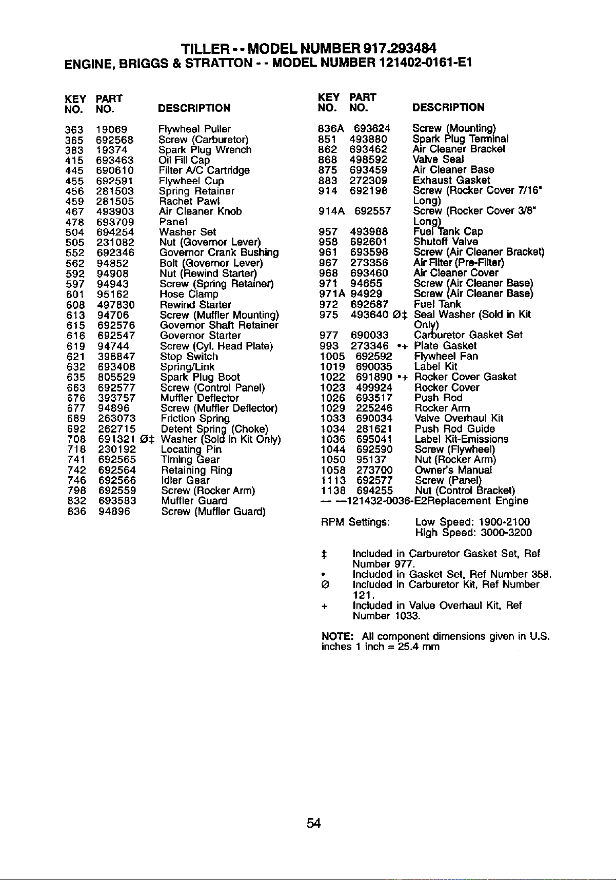
TILLER - - MODEL NUMBER 917.293484
ENGINE, BRIGGS & STRA'n'ON - - MODEL NUMBER 121402-0161-E1
KEY PART KEY PART
NO. NO. DESCRIPTION NO. NO. DESCRIPTION
363 19069 Flywheel Puller 836A 693624 Screw (Mounting)
365 692568 Screw (Carburetor) 851 493880 Spark Plug Terminal
383 19374 Spark Plug Wrench 862 693462 A=r Cleaner Bracket
415 693463 Oil Fill Cap 868 498592 Valve Seal
445 690610 Filter A/C Cartridge 875 693459 Air Cleaner Base
455 692591 Flywheel Cup 883 272309 Exhaust Gasket
456 281503 Spring Retainer 914 692198 Screw (Rocker Cover 7/16"
459 281505 Rachet Pawl Long)
467 493903 Air Cleaner Knob 914A 692557 Screw (Rocker Cover 3/8"
478 693709 Panel Long)
504 694254 Washer Set 957 493988 Fuel Tank Cap
505 231082 Nut (Governor Lever) 958 692601 Shutoff Valve
552 692346 Governor Crank Bushing 961 693598 Screw (Air Cleaner Bracket)
562 94852 Bolt (Governor Lever) 967 273356 Air Filter(Pre-Filter)
592 94908 Nut (Rewind Starter) 968 693460 Air Cleaner Cover
597 94943 Screw (Spring Retainer) 971 94655 Screw (Air Cleaner Base)
601 95162 Hose Clamp 971A 94929 Screw (Air Cleaner Base)
608 497830 Rewind Starter 972 692587 Fuel Tank
613 94706 Screw (Muffler Mounting) 975 493640 _:1: Seal Washer (Sold in Kit
615 692576 Governor Shaft Retainer Only)
616 692547 Governor Starter 977 690033 Carburetor Gasket Set
619 94744 Screw (Cyl. Head Plate) 993 273346 .+ Plate Gasket
621 396847 Stop Switch 1005 692592 Flywheel Fan
632 693408 Spdng/Link 1019 690035 Label Kit
635 805529 Spark Plug Boot 1022 691890 ,+ Rocker Cover Gasket
663 692577 Screw (Control Panel) 1023 499924 Rocker Cover
676 393757 Muffler Deflector 1026 693517 Push Rod
677 94896 Screw (Muffler Deflector) 1029 225246 Rocker Arm
669 263073 Friction Spring 1033 690034 Valve Overhaul Kit
692 262715 Detent Spring (Choke) 1034 281621 Push Rod Guide
708 891321 (_:1:Washer (Sold in Kit Only) 1036 695041 Label Kit-Emissions
718 230192 Locating Pin 1044 692590 Screw (Flywheel)
741 692565 Timing Gear 1050 95137 Nut (Rocker Arm)
742 692564 Retaining Ring 1058 273700 Owner's Manual
746 692566 Idler Gear 1113 692577 Screw (Panel)
798 692559 Screw (Rocker Arm) 1138 694255 Nut (Control Bracket)
832 693583 Muffler Guard -- --121432-O036-E2Replacement Engine
636 94896 Screw (Muffler Guard)
RPM Settings:
Low Speed: 1900-2100
High Speed: 3000-3200
$
+
Included in Carburetor Gasket Set, Ref
Number 977.
Included in Gasket Set, Ref Number 358.
Included in Carburetor Kit, Ref Number
121.
Included in Value Overhaul Kit, Ref
Number 1033.
NOTE: All componentdimensionsgivenin U.S.
inches1 inch= 26.4 mm
54

55

Your Home
For repair - in your home - of all major brand appliances,
lawn and garden equipment, or heating and cooling systems,
no matter who made it, no matter who sold it!
For the replacement parts, accessories and
owner's manuals that you need to do-it-yourself.
For Sears professional installation of home appliances
and items like garage door openers and water heaters.
1-800-4-MY-HOME _ Anytime, day or night
(1-800-469-4663) (U.S.A. and Canada)
www.sears.com www.sears.ca
Our Home
For repair of carry-in products like vacuums, lawn equipment,
and electronics, call or go on-line for the nearest
Sears Parts and Repair Center.
1-800-488-1222 Anytime, dayor night(U.S.A.only)
www.sears.com
To purchase a protection agreement on a product serviced by Sears:
1-800-827-6655 (u.s._) 1-800-361-6665 (Canada)
Para pedir servicio de reparaci6n Au Canada pour service en franqais:
a domicilio, y para ordenar piezas: 1.800_LE_FOYERMC
1-888-SU-HOGAR su (1-800-533-6937)
(1-888-784-6427) www.sears.ca
© Saa_ _ andCo.
® Registered Trademark / TMTrademark / SMService Mark of Seam, Roebuck and Co.
® Mama Registrada / TM Mama de Fdbrica / s_ Mama de Servicio de Seam, Roebuck and Co.
uc Marque de commerce I uo Marque d_pos6e de Seam, Roebuck and Co.
183791 5.14.02 TR Printedin U.S.A.