Loading ...
Loading ...
Loading ...
13
NOTE: ALL ELECTRICAL CONNECTIONS MUST ONLY
BE CARRIED OUT BY A QUALIFIED PERSON.
Each appliance should be connected to an adequately
protected power supply and an isolation switch mounted
adjacent to, but not behind appliance. This switch must
be clearly marked and readily accessible in case of fire.
1. Check electricity supply is correct as shown on
Rating Plate attached to lower front hand side of
front sill panel.
2. Supply terminal connections are located at rear of
appliance. Refer to ‘Electrical Connections’ in
‘Dimensions’ section of manual.
3. Open oven door and remove oven control panel to
allow connection access for electrical supply.
4. Connect mains supply to L1, L2 and L3 connection
terminals. Refer to 'Electrical Supply
Requirements' section for connection details.
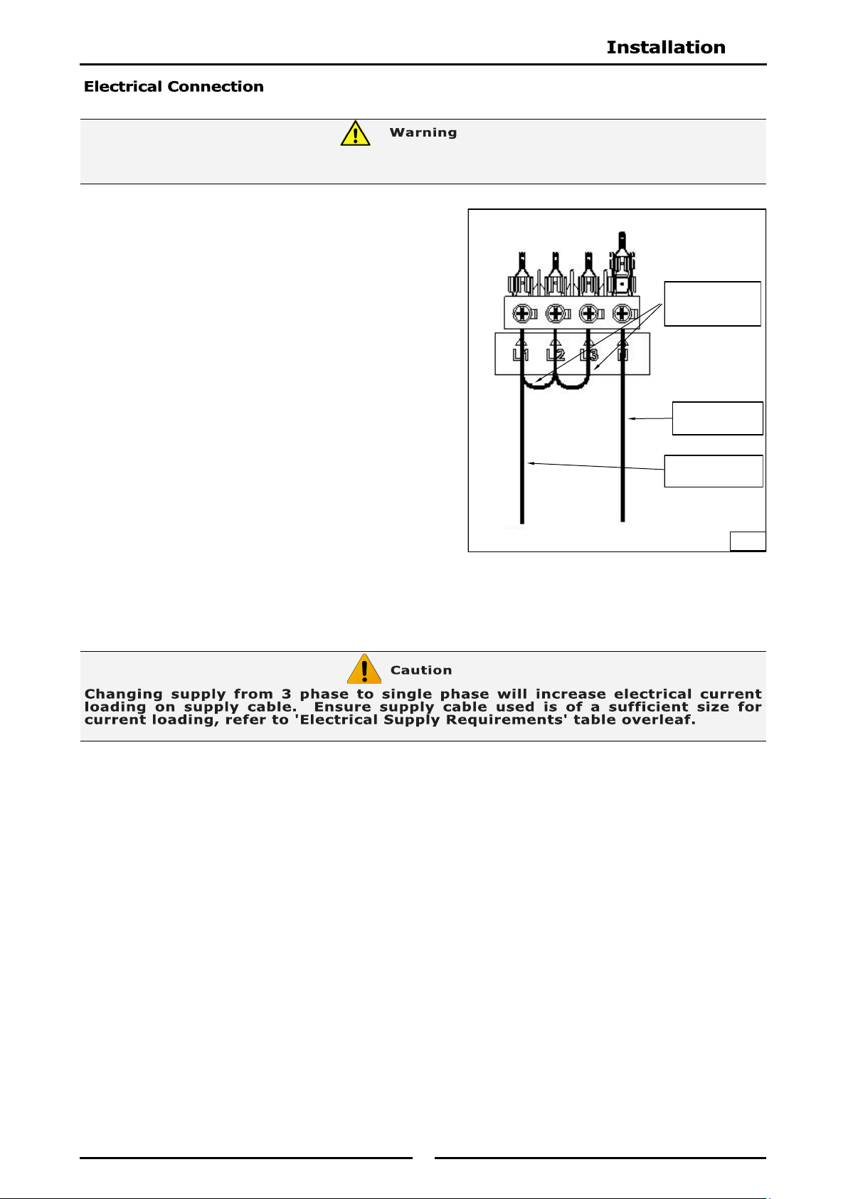
NOTE: This appliance can be converted from 3 Phase to Single Phase supply by connecting single
phase input to L1 and adding a bridge wire between L1, L2 and L3 connections, (refer to Fig
3 above and information shown in 'Electrical Supply Requirements Table' in 'Specifications'
Section).
5. Connect neutral and earth conductors to neutral stud and earth stud respectively.
6. For all connections ensure that conductors are secure and appropriately terminated.
7. Tighten cable gland to secure against tension on cable.
8. Check polarity of each connection is correct to mains connection terminals markings on appliance.
NOTE:
This appliance must be earthed.
Fixed wiring installations must incorporate an all-pole disconnection switch.
9. Correctly locate appliance into its final operating position and using a spirit level, adjust legs so that
appliance is level and at correct height.
10. Connect power supply to appliance.
11. Check electrical supply is within input rating specification, refer to 'Specifications' section).
Add bridging
wires between
L1, L2 and L3.
Neutral sup-
ply connection
Phase supply
connection to L1
P
N
Fig 4
THIS APPLIANCE MUST BE EARTHED. IF SUPPLY CORD IS DAMAGED, IT MUST BE REPLACED BY A SUITABLY
QUALIFIED PERSON IN ORDER TO AVOID A HAZARD.
Loading ...
Loading ...
Loading ...