
GPDR
2-CYCLE GASOLINE POWERED PILE DRIVER
ASSEMBLY & OPERATING INSTRUCTIONS
READ ALL INSTRUCTIONS AND WARNINGS BEFORE USING THIS PRODUCT.
This manual provides important information on proper operation & maintenance. Every effort has
been made to ensure the accuracy of this manual. These instructions are not meant to cover
every possible condition and situation that may occur. We reserve the right to change this
product at any time without prior notice.
IF THERE IS ANY QUESTION ABOUT A CONDITION BEING SAFE OR UNSAFE,
DO NOT OPERATE THIS PRODUCT!
If you experience a problem, have questions or need parts for this product, call Customer Service
at 1-866-460-9436, Monday-Friday, 8 AM - 4 PM Central Time. A copy of the sales receipt is
required.
FOR CONSUMER USE ONLY – NOT FOR PROFESSIONAL USE.
KEEP THIS MANUAL, SALES RECEIPT & APPLICABLE WARRANTY FOR FUTURE
REFERENCE.

!
GPDR!!!!!2'Cycle!Pile!Driver!Instruction!Manual!!!!!!!!!!!!!!!!!!!!!!!!!!!!!!!!!!!!!!!!!!!!!!!!!!!!!!!!!!!!!!!!!!!!!!!!!!!!!!!!!!!!!!!!!!!!!!!!!!!2!
INDEX
I Part Information / Specifications .......................................................................................... 3
II Safety Instructions ............................................................................................................... 4
III Use and Function ................................................................................................................ 4
IV Assembly .............................................................................................................................. 5
V Starting ................................................................................................................................. 7
VI Operation ............................................................................................................................. 7
VII Turning off the Motor ............................................................................................................. 8
VIII Maintenance ......................................................................................................................... 8
IX Troubleshooting .................................................................................................................. 10
X Maintenance Cycle .............................................................................................................. 11
XI Parts List ............................................................................................................................. 12
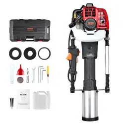
PACKING LIST
1. Pile Driver ......................................................................................................................... 1 Piece
2. Piling Socket Guide SleeveΦ49 ....................................................................................... 1 Piece
3. Piling Socket Guide SleeveΦ69 ....................................................................................... 1 Piece
4. Inner Pile HeadΦ67 .................... ………………………………………………………………1 Piece
5. Oil/Fuel Mix Container ...................................................................................................... 1 Piece
6. Grease for Cylinder (60g) ................................................................................................. 1 Piece
7. Piling Socket Removal Tool ............................................................................................. 1 Piece
8. Instructions ....................................................................................................................... 1 Piece
9. Tool hardware package :
1 piece 4mm inner hexagon spanner
1 piece 5mm inner hexagon spanner
1 piece 6mm inner hexagon spanner
1 piece T-shaped inner hexagon spanner
1 piece straight screwdriver
1 piece 8-10mm open spanner

!
GPDR!!!!!2'Cycle!Pile!Driver!Instruction!Manual!!!!!!!!!!!!!!!!!!!!!!!!!!!!!!!!!!!!!!!!!!!!!!!!!!!!!!!!!!!!!!!!!!!!!!!!!!!!!!!!!!!!!!!!!!!!!!!!!!!3!
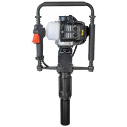
1 Name of Main Parts
No.
Name of Part
No.
Name of Part
No.
Name of Part
1
Combined switch
2
Stop Button
3
Starter
4
Throttle control
button
5
Throttle Button
6
Hammer Case
7
Shock guide
sleeve
8
Piling Socket
9
Support Plate
10
Handle sleeve
11
Damping Spring
12
Locating Sleeve
13
Handle
14
Spark Plug
15
Ventilation Door Switch
16
Air Filter
17
Oil Cover
18
Oil Pot
19
Fuel Bubble
20
Steel Cover
21
Throttle Pull
!
!
!
!
!
!
!
!
!
!
!
!

!
GPDR!!!!!2'Cycle!Pile!Driver!Instruction!Manual!!!!!!!!!!!!!!!!!!!!!!!!!!!!!!!!!!!!!!!!!!!!!!!!!!!!!!!!!!!!!!!!!!!!!!!!!!!!!!!!!!!!!!!!!!!!!!!!!!!4!
SPECIFICATIONS
Engine type Single cylinder, air cooling, 2 stroke, cylinder diameter × stroke: 36×32mm
Fuel Mixed oil (Gasoline: two-stroke engine oil= 50:1)
Fuel tank capacity 1.0675 quart (34.16 ounces)
Weight 28.66 lbs
Displacement 32.7CC
Max power/speed 0.9KW/7500r/min Spark plug type L6T
Max torque/speed 1.45N.m/5000r/min
Fuel consumption ≤0.50L/h
Impact frequency 1700~2230 RPM
Impact energy 20~45J
Carburetor type 1E36F-2E.1A"
EPA Approved
IMPORTANT SAFETY INSTRUCTIONS – SAVE THESE INSTRUCTIONS
1.
The operator must wear slip-resistant safety shoes and suitable clothing. For long-time
operation, the operator must wear goggles, helmet and ear protection.
2.
While operating the machine, please keep balance of body; the user should stand behind the
support handle and operate the machine. While operating the machine, do not smoke, eat or
chat.
3.
After starting the machine, do not carry out one-handed operation.
4.
While lifting the machine, do not pull Throttle Switch.
5.
Non-staff shall stay away from operating area to avoid injury.
6.
Select the medium speed to operate pile driver.
7.
Keep the handle dry and clean without greasy oil or fuel mixture.
8.
If operation is stopped midway: turn off the engine.
9.
Always check whether fastening screws of the connector is tightened before use. If it’s loose, you
must tighten the screws before use.
10.
Gasoline is highly flammable. Replenish fuel in a well-ventilated environment. During fuel
filling,
gasoline engine must be turned off. Do not use pure gasoline, use the appropriate 2-stroke
engine oil.
11.
Do not over fill. The oil shall not exceed the neck of oil filer of Fuel Tank. If fuel spills, wait
until
the fuel volatilizes completely and then start the machine.
12.
Gasoline is highly flammable. Refuel in a well-ventilated environment. When refueling, please turn
off the gasoline engine.
13.
After refueling, tighten the oil lid. During operation, check whether Fuel Tank is damaged and
leaking. If damage is found, turn off the machine immediately for replacement.
14.
While pile driver is used in closed areas of work environment such as tunnels, trenches and
deep
groove, it’s necessary to guarantee normal air circulation to avoid waste gas poisoning
and
suffocation.
15.
Before transport, empty fuel inside Fuel Tank to avoid leakage.
16.
Non-professional maintenance staff are prohibited from dismounting pile driver to avoid
structural
damage of parts, shortened service life of pile driver or accidents.
17.
Before transport, empty fuel inside the oil pot to avoid leakage.
18.
Non-professional maintenance staff are prohibited from dismounting pile driver to avoid structural
damage of parts, shortened service life of pile driver or accidents.

!
GPDR!!!!!2'Cycle!Pile!Driver!Instruction!Manual!!!!!!!!!!!!!!!!!!!!!!!!!!!!!!!!!!!!!!!!!!!!!!!!!!!!!!!!!!!!!!!!!!!!!!!!!!!!!!!!!!!!!!!!!!!!!!!!!!!5!
* NOTE: Piling Socket SleeveΦ49 does NOT need Inner Pile Head.!
ASSEMBLY
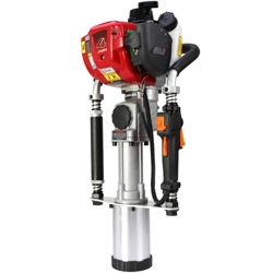
Fig. 1 ) Identify Pile Driver, Piling Socket Sleeves
(2 pieces), Inner Pile Head and Socket Pin.!
Fig. 2 ) Attach Piling Socket Sleeve by
screwing it onto Pile Driver.
Fig. 3 ) Insert Socket Pin, then rotate Piling Socket
Sleeve Φ69 to make sure it is tight & secure.!
Fig. 4 ) Insert Inner Pile Head Φ67. Use a wood
handle or metal bar to force inside Sleeve.
Fig. 5 ) To remove, insert Socket Pin then rotate
Piling Socket Sleeve.
Fig. 6 ) Pull hard and wiggle Piling Socket
Sleeve until it is removed.

!
GPDR!!!!!2'Cycle!Pile!Driver!Instruction!Manual!!!!!!!!!!!!!!!!!!!!!!!!!!!!!!!!!!!!!!!!!!!!!!!!!!!!!!!!!!!!!!!!!!!!!!!!!!!!!!!!!!!!!!!!!!!!!!!!!!!6!
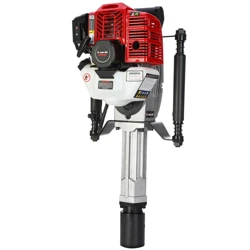
USE AND FUNCTION
Use: Use for outside piling operation for farm fences, orchard fences or barriers.
Function:
• The operator can achieve 360° all-around
operation.
• Can drive posts up to 2.67 inches (68mm) in
diameter.
• Two-way Damping Spring helps reduce vibration.
MIXING GAS/OIL FUEL
Use only quality gasoline and two-stroke special engine oil
.
Recommended mixing ratio:
1. Mix fuel in a container outside in a well ventilated area.
2. Fill certified fuel container with recommended fuel.
3. Add recommended amount of 2 cycle oil.
4. Screw container cap on straight and tight.
5. Shake the container to mix fuel and oil.
6. Unscrew gas cap slowly to vent, add the remainder of
fuel requirements
7. Wipe away any spilled fuel or oil and allow to evaporate before moving or transporting.
STARTING INSTRUCTIONS
Before starting, press the primer button repeatedly until Carburetor is filled with fuel. (If the engine
is cool, close the Choke. Then open Choke after starting.)
!
!
!
!
!
!
!
!
!
!
!
!
!
!
!
!
!
Hold the machine upright. Hold the upper part of handle tightly with one hand, while the other hand
quickly pulls the recoil start. Do not let the recoil handle go back freely. Instead, hold it tightly to
avoid injury.
Condition
Gasoline : 2-Cycle Engine Oil
Operation within 20 hours
50:1
Operation of over 20 hours
50:1
!
Primer!button!
Recoil! Start!
Choke!valve!
(closed!position!in!
cold!conditions)!

!
GPDR!!!!!2'Cycle!Pile!Driver!Instruction!Manual!!!!!!!!!!!!!!!!!!!!!!!!!!!!!!!!!!!!!!!!!!!!!!!!!!!!!!!!!!!!!!!!!!!!!!!!!!!!!!!!!!!!!!!!!!!!!!!!!!!7!
When the engine has started, open the choke completely. After idling for approximately 5 minutes,
you can start working.
OPERATION
After engine is started, allow 5 minutes idle operation to warm up the machine.
When the engine is warmed up, press throttle handle to the appropriate speed.
Note: The unit will provide low or medium-speed for work in the first 6 hours of operation and the
maximum throttle should not be used.
High-speed operation of pile driver during non-piling is prohibited.
TURNING OFF MOTOR
Release throttle handle and allow
to idle for 3-5 minutes.
Pull Stop Switch.
MAINTENANCE
Fuel filter
If the fuel filter is blocked, the pile driver will have reduced speed and weaker impact energy.
① Open the Fuel Tank
lid. Remove fuel filter from Fuel Tank with a metal hook or pliers.
② When cleaning the fuel filter, clean
the Fuel Tank at same time. See Fig.14, 15 and 16.
Stop!Button!
Fig.!14!
Fig.!13!
Fig.!15!

!
GPDR!!!!!2'Cycle!Pile!Driver!Instruction!Manual!!!!!!!!!!!!!!!!!!!!!!!!!!!!!!!!!!!!!!!!!!!!!!!!!!!!!!!!!!!!!!!!!!!!!!!!!!!!!!!!!!!!!!!!!!!!!!!!!!!8!
Fig.!18!
Fig.!19!
Fig.!17!
Air Filter
Check air filter regularly. Soot deposit blocking air filter will reduce power of gasoline engine
and
service life. If the filter has too much soot deposit, clean it with warm water and detergent, and then
wipe
dry it with dry cloth, and then install the air filter. Replace Filter if damaged. If working in
a
dusty
environment, maintenance cycle will be shortened.
Silencer
Regularly remove dirt on inlet and outlet of silencer, or clean dirt in it with detergent.
Cylinder Cooling Fin
Regularly remove dust to ensure the cylinder cooling conditions are well. The gasoline pile driver
is air-cooling type. If dust gathers on the cylinder cooling fin, the cooling effect will be influenced
directly.
Carburetor
When the machine is not used for more than one week, be sure to completely remove the fuel.
Pull out the oil inlet pipe, press Primer Button of carburetor repeatedly for oil discharge, and
return the oil inlet pipe back to its
position when fuel in Fuel Bubble and oil return pipe is empty.
Spark Plug
Remove sediment with a wire brush.
Spark Plug gap is 0.5-0.7 mm.
Add lubricating oil to impact cylinder
After the machine has been working for 50 hours, the included special grease should be added to
the impact cylinder. Open the cover of gear boxes and lubricate the gear and
the connecting rod with lubricating oil as shown in Fig. 17, 18, 19.

!
GPDR!!!!!2'Cycle!Pile!Driver!Instruction!Manual!!!!!!!!!!!!!!!!!!!!!!!!!!!!!!!!!!!!!!!!!!!!!!!!!!!!!!!!!!!!!!!!!!!!!!!!!!!!!!!!!!!!!!!!!!!!!!!!!!!9!
TROUBLESHOOTING
Problem analysis and solving
Example 1: Difficulties in starting cool engine.
→Wipe dry Spark Plug
↓
→Replace Spark Plug
↓
→Reduce the fuel supply
Example 2: Restarting after sudden stop
↓
→Refill Fuel tank or
clean
carburetor
→Clean fuel filter
↓
→ Remove carbon deposit of
Spark Plug and clean filter
element
Example 3: Slow, weak power
→Remove carbon deposit
↓
→Clean
↓
→ Clean filter
Example 4: Loud Sound
→Remove carbon deposit
↓
→ Replace
Example 5: The machine is working normally but the work efficiency is very low
→Replace or renew
Rubber ring of impact piston is aged and worn
Spark Plug is damp
Spark plug produces electric spark
Too much fuel absorbed
Fuel is used up or carburetor is blocked
Fuel filter is blocked
Too much carbon deposit of Spark Plug
Carbon deposit of the cylinder or silencer
The oil tube and the Fuel Tank air vent blocked
Air filter is blocked
Carbon deposit found in combustion chamber
Serious abrasion in active components

!
GPDR!!!!!2'Cycle!Pile!Driver!Instruction!Manual!!!!!!!!!!!!!!!!!!!!!!!!!!!!!!!!!!!!!!!!!!!!!!!!!!!!!!!!!!!!!!!!!!!!!!!!!!!!!!!!!!!!!!!!!!!!!!!!!!!10!
MAINTENANCE
The following data is provided for common use of the
product.
Under worse working conditions such as
thick dust or longer
work hours, the maintenance
cycle should be
shortened.
Before work
After work or every day
After Filling oil
Every Week
Every Month
Temporary Failure
If necessary
The whole machine
Outlook check (state,
tightness
of
screws)
√
√
Clean
√
Control handle/stop button
Function check
√
√
Air Filter
Clean
√
√
Replace
√
Fuel Filter
Check
√
Replace
√
Petrol Tank/Petrol
Tank
cover
Clean
√
√
Check
√
√
Tighten
√
Gear Box/Cylinder
Clean
√
Add oil
√
Silencer
Check
√
Remove carbon deposit
√
Cylinder Cooling Fin
Check
√
Clean
√
Spark Plug
Check/Adjust the distance
between electrodes
√
Replace
√
Screw and Nut
Check
√
√
Tighten
√

!
GPDR!!!!!2'Cycle!Pile!Driver!Instruction!Manual!!!!!!!!!!!!!!!!!!!!!!!!!!!!!!!!!!!!!!!!!!!!!!!!!!!!!!!!!!!!!!!!!!!!!!!!!!!!!!!!!!!!!!!!!!!!!!!!!!!11!
PARTS LIST
Part No.
Name
Qty
Part No.
Name
Qty
1
Recoil Start Assembly - Screw
1
41
Piston Ring
1
2
Recoil Start Assembly - Start Wheel
1
42
Cylinder Gasket
1
3
Recoil Start Assembly - Rope Sheave
1
43
Cylinder Body
1
4
Recoil Start Assembly - Rope
1
44
Screw Assembly M5x18
4
5
Recoil Start Assembly - Starter Flat Spring
1
45
Cylinder Cover Assembly
1
6
Recoil Start Assembly - Shell
1
46
Screw Assembly M5x16
1
7
Screw Assembly M5X25
6
47
Spark Plug
1
8
Recoil Start Assembly - Starter Handle
1
48
Spark Plug Jump Ring
1
9
Recoil Start Assembly - Cover
1
49
Spark Plug Cover
1
10
Recoil Start Assembly - Compressed
Spring
1
50
High Voltage Cap
1
11
Recoil Start Assembly - Start Button Pole
1
51
Rubber Plug
1
12
Starter
1
52
Upper Gland
1
13
Starter Pad
1
53
Silencer Pad
1
14
Starter Hub
1
54
Silencer
1
15
Small Oil Seal
1
55
Screw Assembly M5x12
2
16
Rear Half Crankcase
1
56
Washer 5
2
17
Crankcase Seal Pad
1
57
Screw Assembly M6x60-12.9
2
18
Bearing 6202/P6
2
58
Intake Gasket
1
19
Crank Connected Rod Group
1
59
Intake
1
20
Woodruff-Key 3X3X13
1
60
Carburetor Mat
1
21
Pin B4X10
4
61
Carburetor
1
22
Front Half Crankcase
1
62
Choke Valve Handle
1
23
Screw Assembly M5X30
4
63
Retaining Plug
1
24
Magneto Rotor
1
64
Nut M4
1
25
Washer 8
1
65
Air Filter Inner Cover
1
26
Washer 8
1
66
Screw Assembly M5x55
2
27
Nut M8
1
67
Choke Valve
1
28
Magneto Stator
1
68
Tapping Screw ST4.2X12
1
29
Stall Quad
1
69
Filter Element
1
30
Screw Assembly M5x20
2
70
Air Filter Outer Cover
1
31
Washer B
2
71
Big Head Screw
1
32
Tension Spring
1
72
Fuel Tank Rack
1
33
Tensioning Block
2
73
Rubber Sleeve
1
34
Wave Washer
2
74
Fuel Filter
1
35
Screw Shaft
1
75
Rubber Tube
1
36
Magneto Casing
1
76
Oil Tube Rubber Plug
1
37
Small Needle Roller Bearing
1
77
Soft PVCLS-3X1X75
1
38
Piston Pin Baffle Ring
2
78
Screw Assembly M5x16
2
39
Piston
1
79
Fuel Tank
1
40
Piston Pin
1
80
Gas Cap Chain
1
Part No.
Name
Qty
Part No.
Name
Qty
81
End Cover
87
Rubber Pad
2
82
Oil Pot Inner Cover
1
88
Heat Shield
1
83
Suction Nozzle
1
89
Screw Assembly M4X8
1
84
Gasket
1
90
Washer 5
2
85
Oil Cover
1
91
Gas Guide Tube
1
86
Tank Cover Assembly
1

!
GPDR!!!!!2'Cycle!Pile!Driver!Instruction!Manual!!!!!!!!!!!!!!!!!!!!!!!!!!!!!!!!!!!!!!!!!!!!!!!!!!!!!!!!!!!!!!!!!!!!!!!!!!!!!!!!!!!!!!!!!!!!!!!!!!!12!
PARTS DIAGRAM

!
GPDR!!!!!2'Cycle!Pile!Driver!Instruction!Manual!!!!!!!!!!!!!!!!!!!!!!!!!!!!!!!!!!!!!!!!!!!!!!!!!!!!!!!!!!!!!!!!!!!!!!!!!!!!!!!!!!!!!!!!!!!!!!!!!!!13!
PARTS LIST
Parts No.
Name
Qty
Parts No.
Name
Qty
1
Gasoline Engine
1
41
Right Paper Pad
1
2
Clutch Plate
1
42
Right Steel Cover
1
3
Circlip for Hole A Type 40
2
43
Ram O-ring
1
4
Deep Groove Ball Bearing 6203-2RZ
4
44
Ram
1
5
Bevel Pinion
1
45
Impact Cylinder
1
6
Reduction Gearbox
1
46
Shock
1
7
Hexagon Socket Head Cap Screw M6×8
3
47
Shock O-ring
2
8
Flat Gasket Φ16XΦ22X0.5
1
48
Crash Pad
2
9
Bevel Gear Wheel
1
49
Wave Washer Φ39×46×0.5
6
10
Flat Gasket 10
1
50
Shock Guide Sleeve
1
11
Elastic Washer 10
1
51
Piling Socket 69
1
12
Hexagon Thin Nut M10
1
13
Right Paper Pad
1
14
Right Steel Cover
1
15
Hexagon Socket Head Cap Screw M5×14
12
16
Elastic Washer 6
5
17
Hexagon Socket Head Cap Screw M6×20
4
18
Impact Piston
1
19
Impact Piston Pin
1
20
Impact Piston O-ring
2
21
Handle Soft Cover
1
22
Handle
1
23
Locating Sleeve
2
24
Hexagon Socket Head Cap Screw M6×35
2
25
Damping Spring
4
26
Guide Sleeve
2
27
Combined Switch
1
28
Support Plate
1
29
Hammer Case
1
30
Elastic Washer 8
10
31
Hexagon Socket Head Cap Screw m8×30
10
32
Outer-Hexagonal Flange Self-Locking Nut
M18×1.5
2
33
Handle Connecting Thread Joint
2
34
Handle Sleeve
1
35
Handle Soft Sleeve
1
36
Impact Crank
1
37
Needle Bearing HK152316
1
38
Impact Connecting Rod
1
39
Retainer Ring
1
40
Hexagon Socket Head Cap Screw m6×16
1

!
GPDR!!!!!2'Cycle!Pile!Driver!Instruction!Manual!!!!!!!!!!!!!!!!!!!!!!!!!!!!!!!!!!!!!!!!!!!!!!!!!!!!!!!!!!!!!!!!!!!!!!!!!!!!!!!!!!!!!!!!!!!!!!!!!!!14!
PARTS DIAGRAM
!

!
GPDR!!!!!2'Cycle!Pile!Driver!Instruction!Manual!!!!!!!!!!!!!!!!!!!!!!!!!!!!!!!!!!!!!!!!!!!!!!!!!!!!!!!!!!!!!!!!!!!!!!!!!!!!!!!!!!!!!!!!!!!!!!!!!!!15!
!
EMISSION!CONTROL!SYSTEM!!WARRA NTY!!!!BUFFALO!CORPORATION!
Your Warranty Rights and Obligations
The California Air Recourse Board, U.S. EPA and Buffalo Corp. are pleased to explain the Emission Control System
Warranty on your 2019 model year new outdoor power equipment engine.
California!
In California, new spark-ignited small off-road equipment engines must be designed, built and equipped to meet the State’s
stringent anti-smog standards.
Other States, U.S. Territories
In other areas of the United States, your engine must be designed, built and equipped to meet the U.S. EPA emission
standards for spark-ignited engines at or below 19 kilowatts.
All!of!the!United!States!
Buffalo Corp. must warrant the emission control system on your power equipment engine for the periods of time listed below
provided there has been no abuse, neglect or improper maintenance of your power equipment engine. Where a warrantable
condition exists, Buffalo Corp. will repair your power equipment engine at no cost to you including diagnosis, parts and
labor.
Your emissions control system may include parts such as: carburetors or fuel injection system, ignition system, catalytic
converters, fuel tanks, valves, filters, clamps, connectors, and other associated components. Also, included may be hoses,
belts, connectors, sensors, and other emission-related assemblies.
Manufacturer’s Warranty Coverage:
The emission control system is warranted for two years. If any emissions-related part on your engine is defective, the part
will be repaired or replaced by Buffalo Corp.
Owner’s Warranty Responsibility
As the power equipment engine owner, you are responsible for the performance of the required maintenance listed in your
owner’s manual. BUFFALO CORP. recommends that you retain all receipts covering maintenance on your power
equipment engine, but BUFFALO CORP. cannot deny warranty solely for the lack of receipts or for your failure to ensure the
performance of all scheduled maintenance.
As the power equipment engine owner, you should however be aware that BUFFALO CORP. may deny your warranty
coverage if your power equipment engine or a part has failed due to abuse, neglect, improper maintenance or unapproved
modifications.
You are responsible for presenting your power equipment engine to distribution center or service center authorized by
BUFFALO CORP. as soon as the problem exists. The warranty repairs should be completed in a reasonable amount of
time, not to exceed 30 day.
If you have any questions regarding your warranty rights and responsibilities, you should contact Buffalo Corp. customer
service representative at 1-866-460-9436 or write to info@buffalotools.com
DEFECTS WARRANTY COVERAGE
Adopted by the Air Resources Board, Buffalo Corp. warrants to the ultimate purchaser and each subsequent purchaser that
the small off-road engine (SORE)(1) has been designed, built and equipped so as to conform with all applicable regulations;
and (2) is free from defects in materials and workmanship that cause the failure of a warranted part to conform with those
regulations as may be applicable to the terms and conditions stated below.
The warranty period begins on the date the engine is delivered to an ultimate purchaser or first placed into service. The
warranty period is two years.
Subject to certain conditions and exclusions as stated below, the warranty on emissions related parts is as follows:
Any warranted part that is not scheduled for replacement as required maintenance in your Owner’s Manual is warranted for
the warranty period stated above. If the part fails during the period of warranty coverage, the part will be repaired or
replaced by Buffalo Corp. According to Subsection (4) below. Any such part repaired or replaced under warranty will be
warranted for the remainder of the periods.
Any warranted part that is scheduled only for regular inspection in your owner’s manual is warranted for the warranty period
stated above. Any such part repaired or replaced under warranty will be warranted for the remaining warranty period.
Any warranted part that is scheduled for replacement as required maintenance in your owner’s manual is warranted for the
period of time before the first scheduled replacement date for that part. If the part fails before the first scheduled
replacement, the part will be repaired or replaced by Buffalo Corp. According to Subsection (4) below. Any such part
repaired or replaced under warranty will be warranted for the remainder of the period prior to the first scheduled
replacement point for the part.

!
GPDR!!!!!2'Cycle!Pile!Driver!Instruction!Manual!!!!!!!!!!!!!!!!!!!!!!!!!!!!!!!!!!!!!!!!!!!!!!!!!!!!!!!!!!!!!!!!!!!!!!!!!!!!!!!!!!!!!!!!!!!!!!!!!!!16!
Repair or replacement of any warranted part under the warranty provisions herein must be performed at a warranty station
at no charge to the owner.
Notwithstanding the provisions herein, warranty services or repair will be provided at all of our distribution centers that are
franchised to service the subject engines.
The engine owner must not be charged for diagnostic labor that leads to the determination that a warranted part is in fact
defective, provided that such diagnostic work is performed at a warranty station.
Buffalo Corp. is liable for damages to other engine components proximately caused by a failure under warranty of any
warranted part.
Throughout the engine warranty period stated above, Buffalo Corp. will maintain a supply of warranted part sufficient to
meet the expected demand for such parts.
Any replacement may be used in the performance of any warranty maintenance or repairs and must be provided without
charge to the owner. Such use will not reduce the warranty obligations of Buffalo Corp.
Add-on or modified parts that are not exempted by the Air Resources Board may not be used. The use of any non-
exempted add-on or modified parts by the ultimate purchaser will be grounds for disallowing a warranty claims. Buffalo
Corp. will not be liable to warrant failures of warranted parts caused by the use of a non-exempted add-on or modified part.
The manufacturer issuing the warranty shall provide any documents that describe that manufacturer’s warranty procedures
or policies within five working days of request by the Air Resources Board.
EMISSION WARRANTY PARTS LIST
(1) Fuel Metering System:
(a) Gasoline carburetor assembly and its internal components
(b) Carburetor gaskets
(c) Fuel line
(d) Clamps
(e) Fuel tank
(f) Fuel line fittings
(g) pressure regulator (if equipped)
(h) Mixer assembly and its internal components (if equipped)
(2) Air induction system including: (a) Intake pipe/manifold
(b) Air cleaner
(3) Ignition system including: (a) Spark plug (b) Ignition coil
(4) Catalytic muffler assembly including: (a) Muffler gasket (b) Exhaust manifold (c) Catalytic converter if
available
(5) Crankcase breather assembly including (a) Breather connection tube
(6) Fuel tank evaporative emissions control system including:
(a) Purge valves (b) Carbon canister (c) canister Mounting Brackets (d) Fuel Cap (e) Fuel Tank
(7) Miscellaneous items used in above systems including: (a) Switches (b) Hoses, belts connectors, and
assemblies
(8) Air injection system (a) Pulse valve
!
2 0 1 9 12