Loading ...
Loading ...
Loading ...
9
English
FUNCTIONAL DESCRIPTION
NOTE
The information contained in this instruction manual is designed to assist you in the safe operation and maintenance
of the power tool.
Never operate, or attempt any maintenance on the tool unless you have fi rst read and understood all safety
instructions contained in this manual.
Some illustrations in this instruction manual may show details or attachments that diff er from those on your own
power tool.
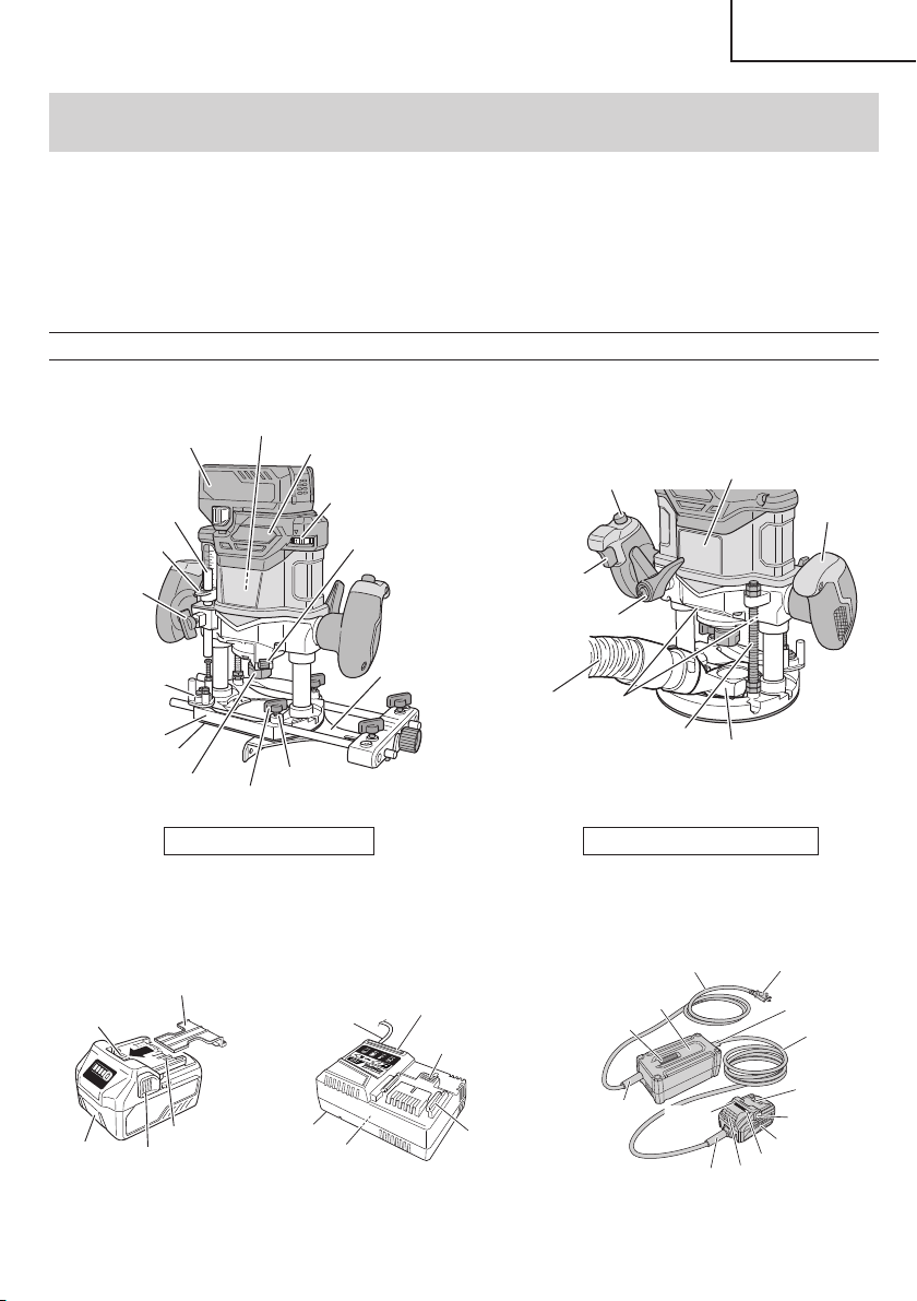
NAME OF PARTS
1. Cordless router (M3612DA)
Stopper pole
Depth
indicator
Wing bolt
Stopper block
Sub base
Collet chuck
Wing bolt (A)
Lock spring
Straight guide
Lock pin
Dial
Head cover
Battery
Motor
Base
With straight guide attached
Name plate
Handle
Threaded column
Dust Collector
Hose
(Cleaner)
LED light
Lock lever
Switch trigger
ON/OFF
Lock button
Rearview/without straight guide
Fig. 2
2. Battery 3. Battery Charger 4. AC/DC Adapter
(optional accessories…sold separately)
Battery
Latch
Ventilation holes
Terminals
Battery cover
Ventilation
holes
Body
Cord
Nameplate
Charge
indicator lamp
Guide rail
Plug
Latch
Ventilation holes
Terminals
AC cord
DC cord
Box
Cord armor
Cord armor
Cord armor
Adapter
Error lamp
Error lamp
Power
lamp
<BSL36A18>
Fig. 3
<UC18YSL3>
Fig. 4
<ET36A>
Fig. 5
00BookM3612DANA.indb900BookM3612DANA.indb92020/11/189:52:362020/11/189:52:36
Loading ...
Loading ...
Loading ...