Loading ...
Loading ...
Loading ...
15
English
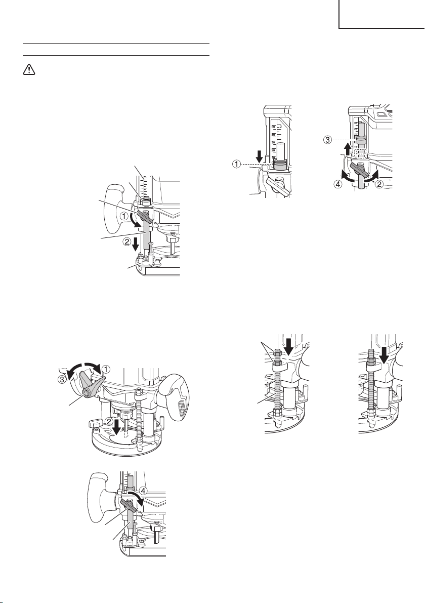
(4) Tighten wing bolt. Align the depth indicator with the
“0” graduation of scale. (Fig. 15 (a))
(5) Loosen wing bolt, and raise until indicator aligns
with the graduation representing the desired cutting
depth. Tighten wing bolt. (Fig. 15 (b))
(b)(a)
“0”
Fig. 15
(6) Loosen the lock lever and press the tool body down
until the stopper block to obtain the desired cutting
depth.
As shown in Fig. 16 (a), loosening the two nuts on the
threaded column and moving them down will allow you to
move down to the end position of the bit when the lock
lever was loosened. This is helpful when moving the
router to align the bit with the cutting position. As shown
in Fig. 16 (b), tighten the upper and lower nuts to secure
the cutting depth.
(b)(a)
Nuts
Threaded
Column
Fig. 16
NOTE
○
Raise the power tool to the upper limit position and
make sure that the bit is not touching the material.
○
The two nuts attached to the base are for securing
threaded column. Do not loosen the nuts. Also,
check to see if they are loose and tighten them when
necessary.
PRIOR TO OPERATION
WARNING
To avoid serious accident, ensure the switch is in
the OFF position, and pull out the battery.
1. Adjusting depth of cut
<Using the stopper pole>
(1) Place the tool on a fl at wood surface.
(2) Loosen wing bolt allowing the stopper pole to contact
with stopper block. (Fig. 13)
Depth indicator
Wing bolt
Stopper pole
Stopper block
Scale
Fig. 13
(3) Loosen the lock lever and press the tool body until the
bit just touches the fl at surface. Tighten the lock lever
at this point.
Tighten the wing bolt and also secure the stopper
pole. (Fig. 14)
Lock lever
Wing bolt
Stopper pole
Fig. 14
00BookM3612DANA.indb1500BookM3612DANA.indb152020/11/189:52:382020/11/189:52:38
Loading ...
Loading ...
Loading ...