1
Owner’s Manual
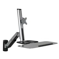
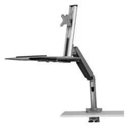
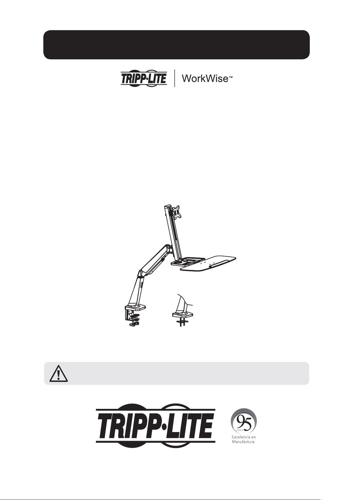
Single-Display Sit-Stand
Desk-Mount Workstation
Model: WWSS1332C
1111 W. 35th Street, Chicago, IL 60609 USA • www.tripplite.com/support
Copyright © 2017 Tripp Lite. All rights reserved.
CAUTION: DO NOT EXCEED MAXIMUM LISTED WEIGHT CAPACITY
(17.6 lb. / 8 kg). SERIOUS INJURY OR PROPERTY DAMAGE MAY OCCUR!
PROTECT YOUR INVESTMENT!
Register your product for quicker service and ultimate peace of mind.
You could also win an ISOBAR6ULTRA surge protector—a $100 value!
www.tripplite.com/warranty
Español 10 • Français 19 •
Русский
28 • Deutsch 37
2
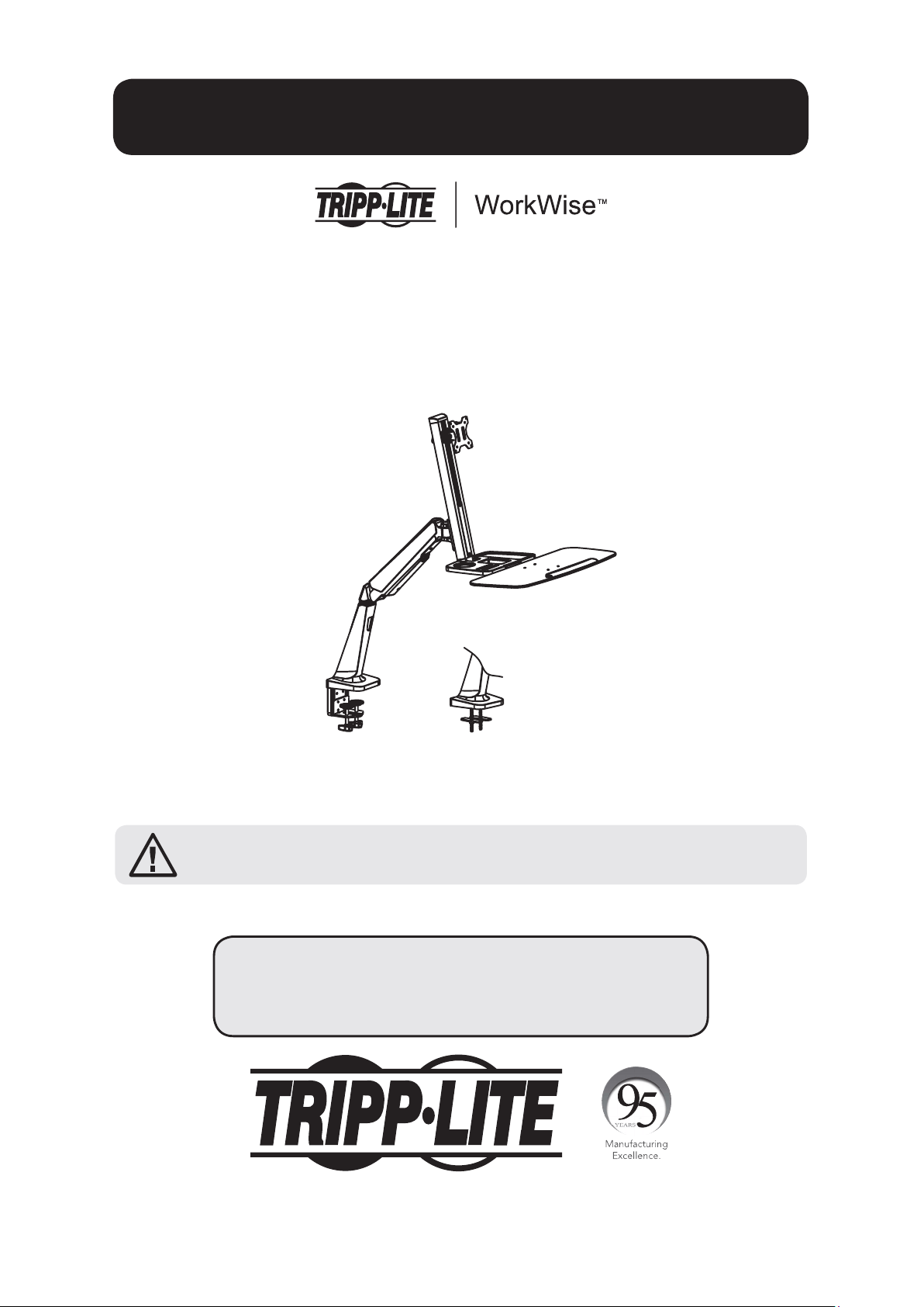
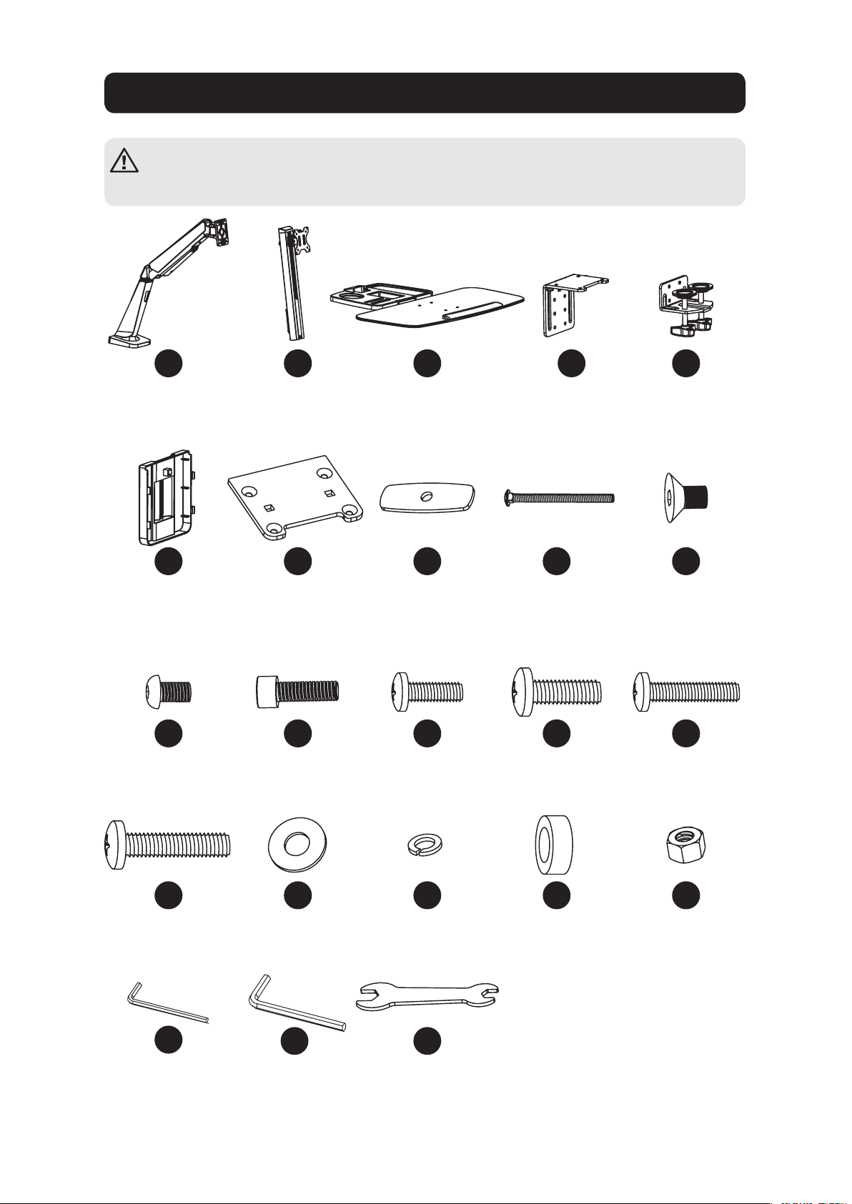
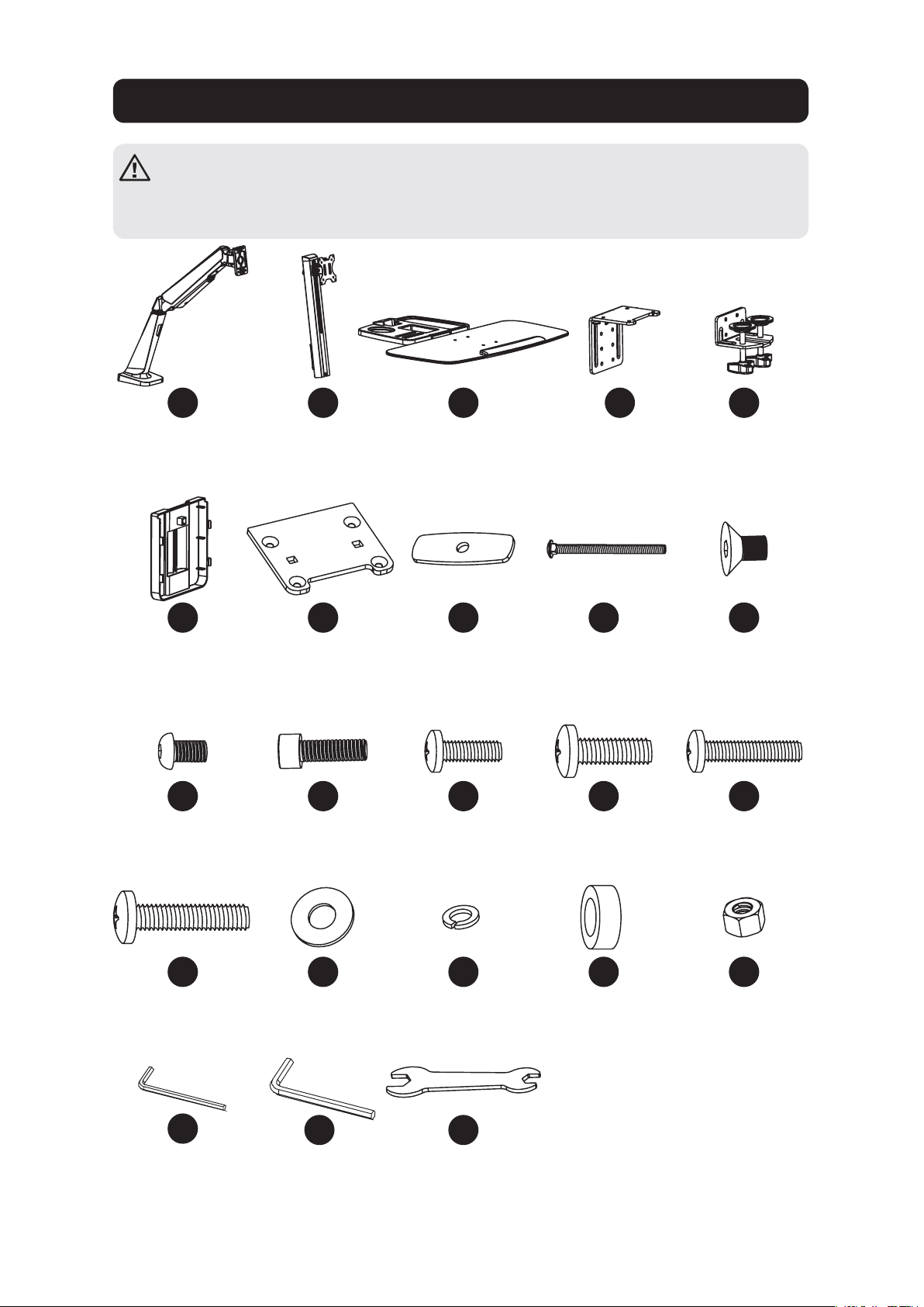
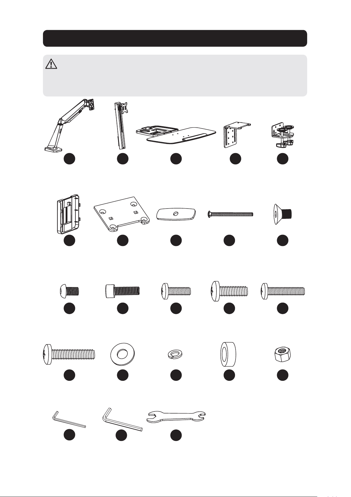
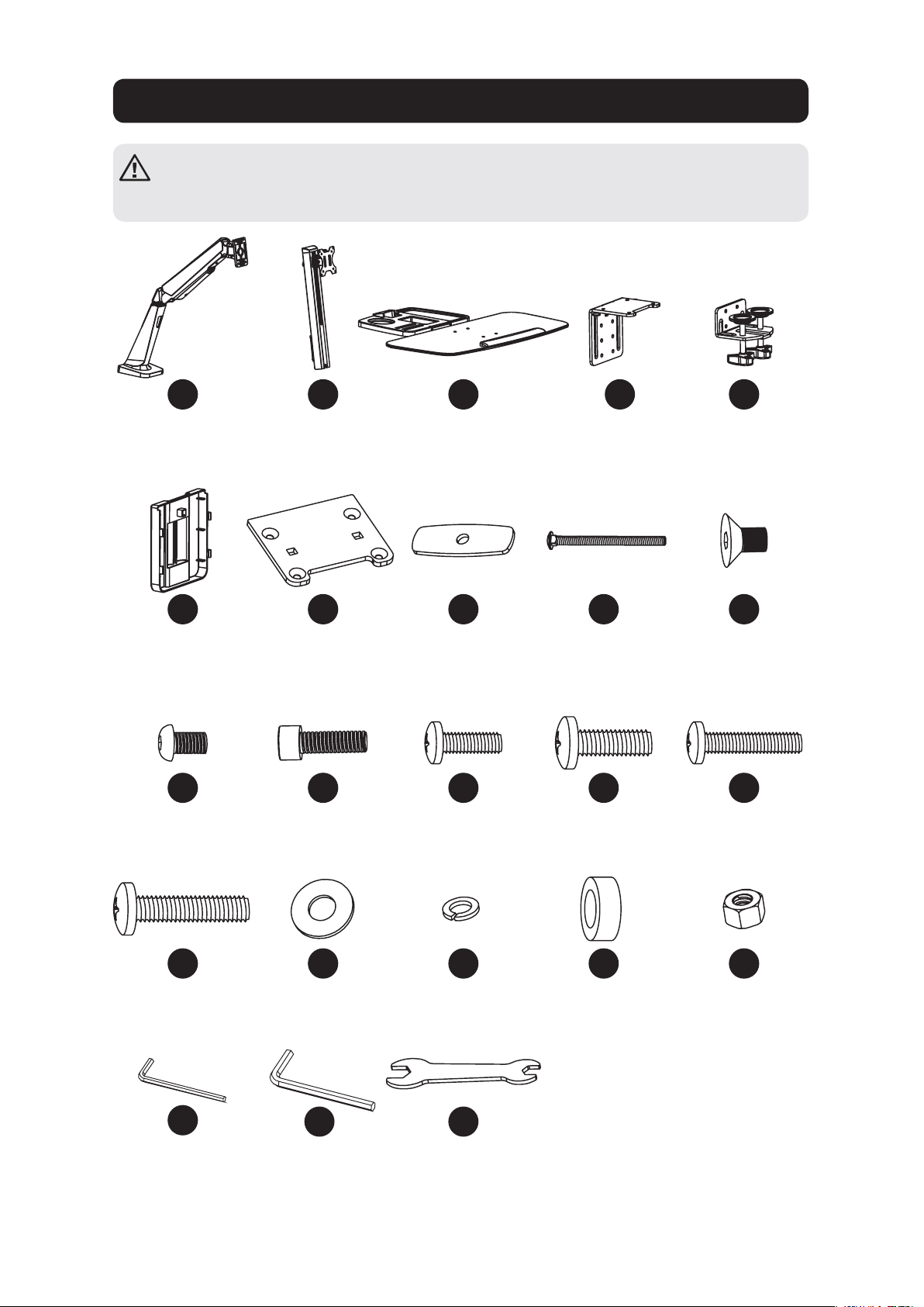
Component Checklist
IMPORTANT: Ensure all parts according to the component checklist have been
received prior to installation. If any parts are missing or faulty, visit
www.tripplite.com/support for service.
A
F
K
P
U
B
G
L
Q
D
I
N
S
E
J
O
T
W
C
H
M
R
V
Bracket Arm
x1
Cable Clamp
x1
M6 x 12
x4
M5 x 16
x4
4 mm Hex Key
x1
Support Mast
x1
Grommet
Mount Plate
x1
M8 x 25
x2
5 x 12 x 1
x4
Keyboard Shelf
x1
Pressure Plate
x2
M4 x 12
x4
D8
x2
6 mm Hex Key
x1
Clamp Top
x1
M8 x 105
x2
M5 x 12
x4
8 x 5 Spacer
x4
Clamp Bottom
x1
M6 x 10
x4
M4 x 16
x4
M8
x2
Wrench
x1
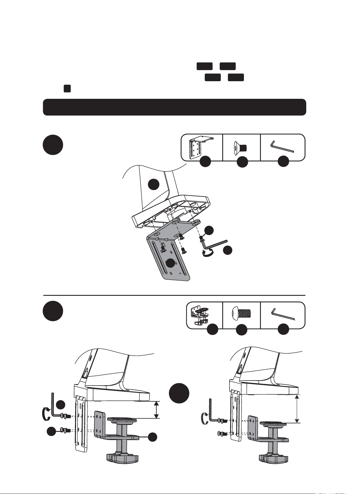
3
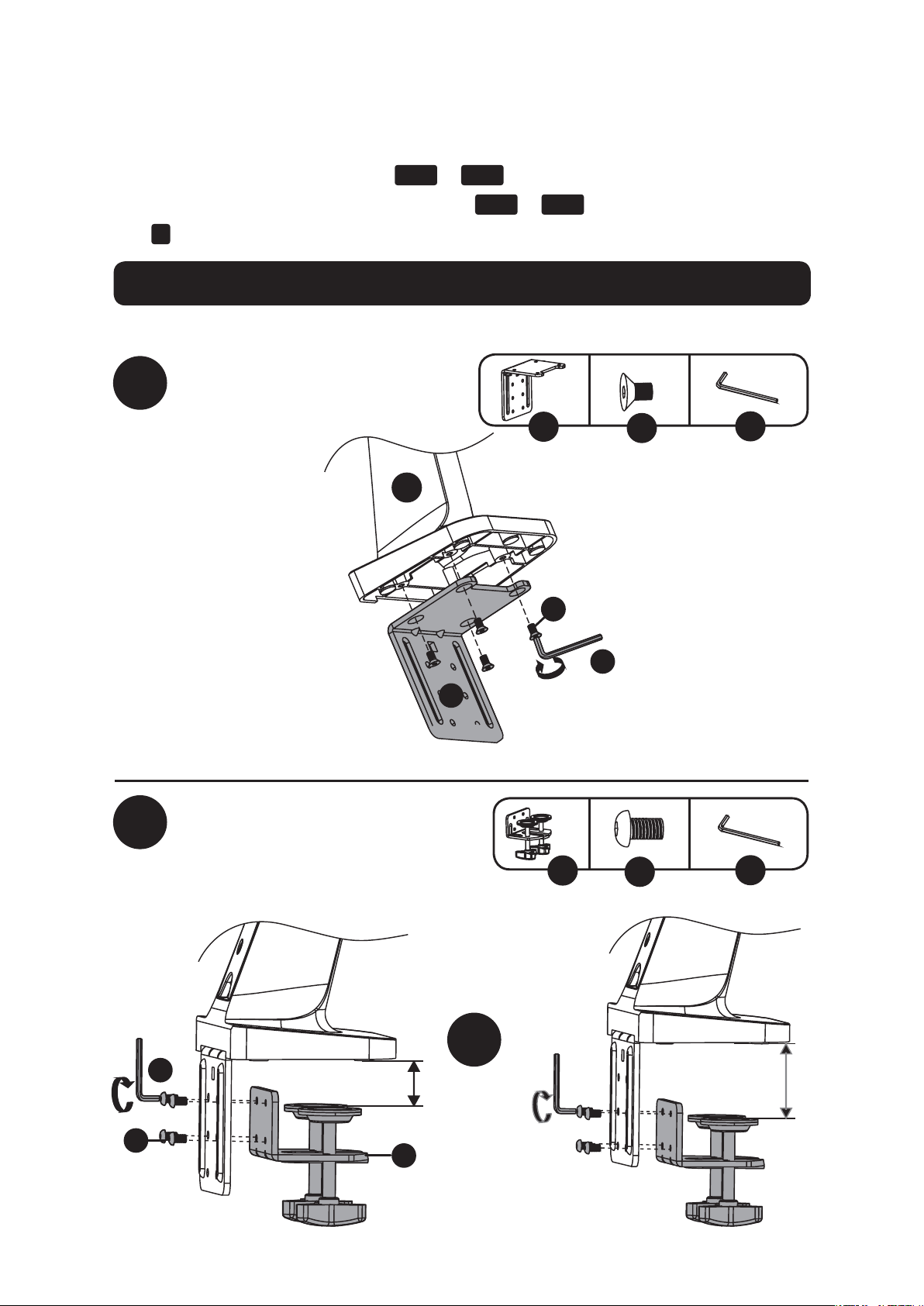
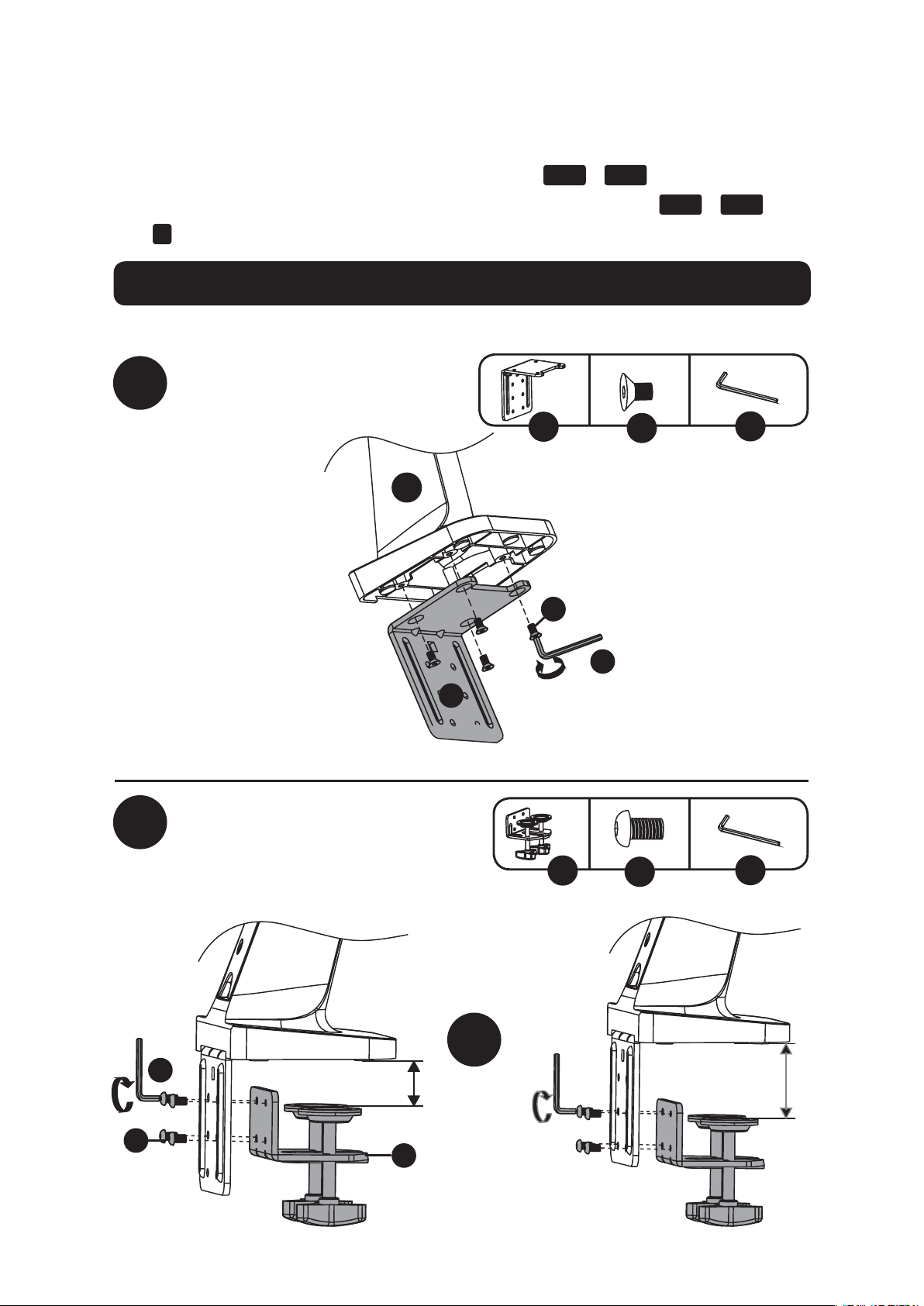
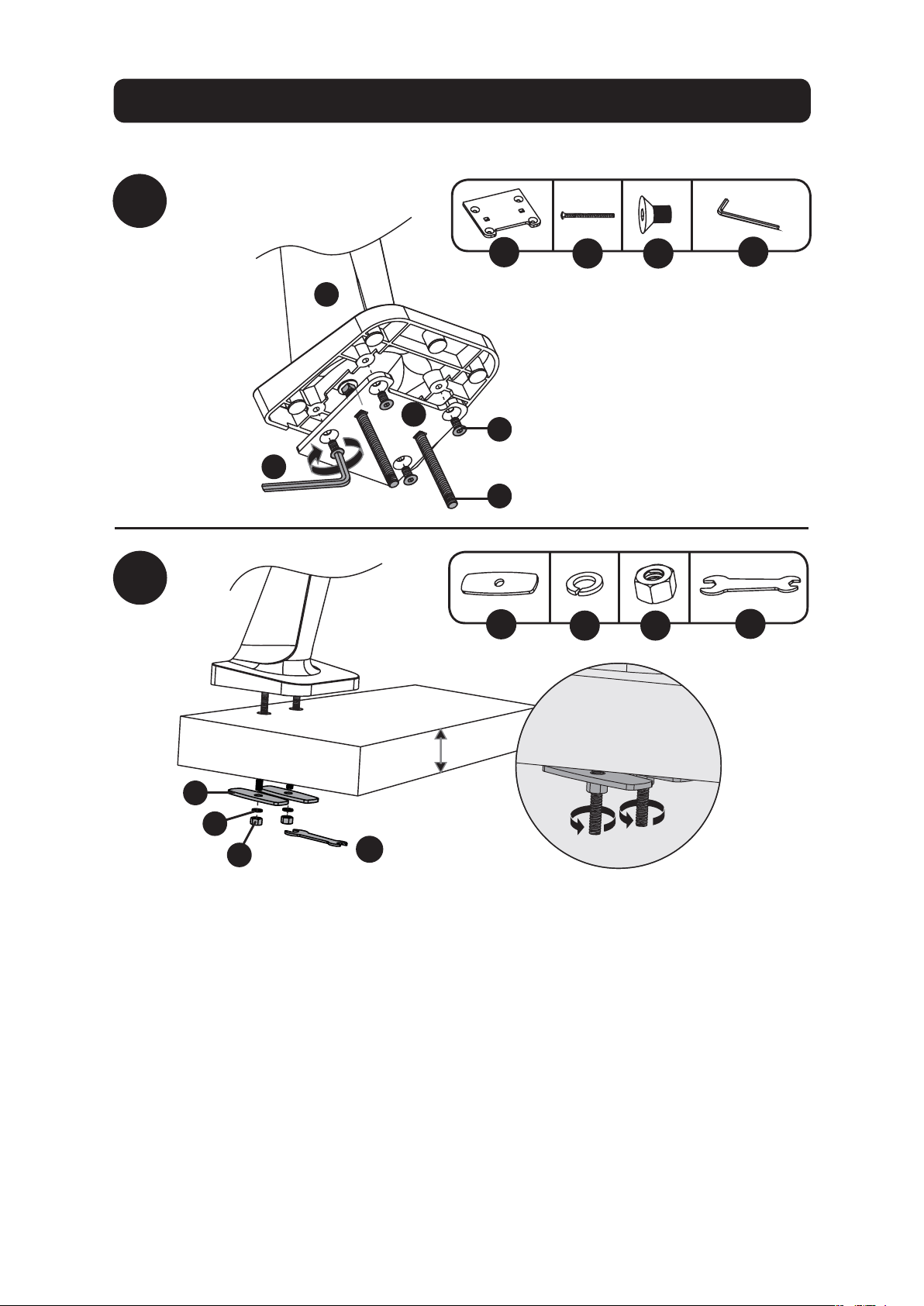
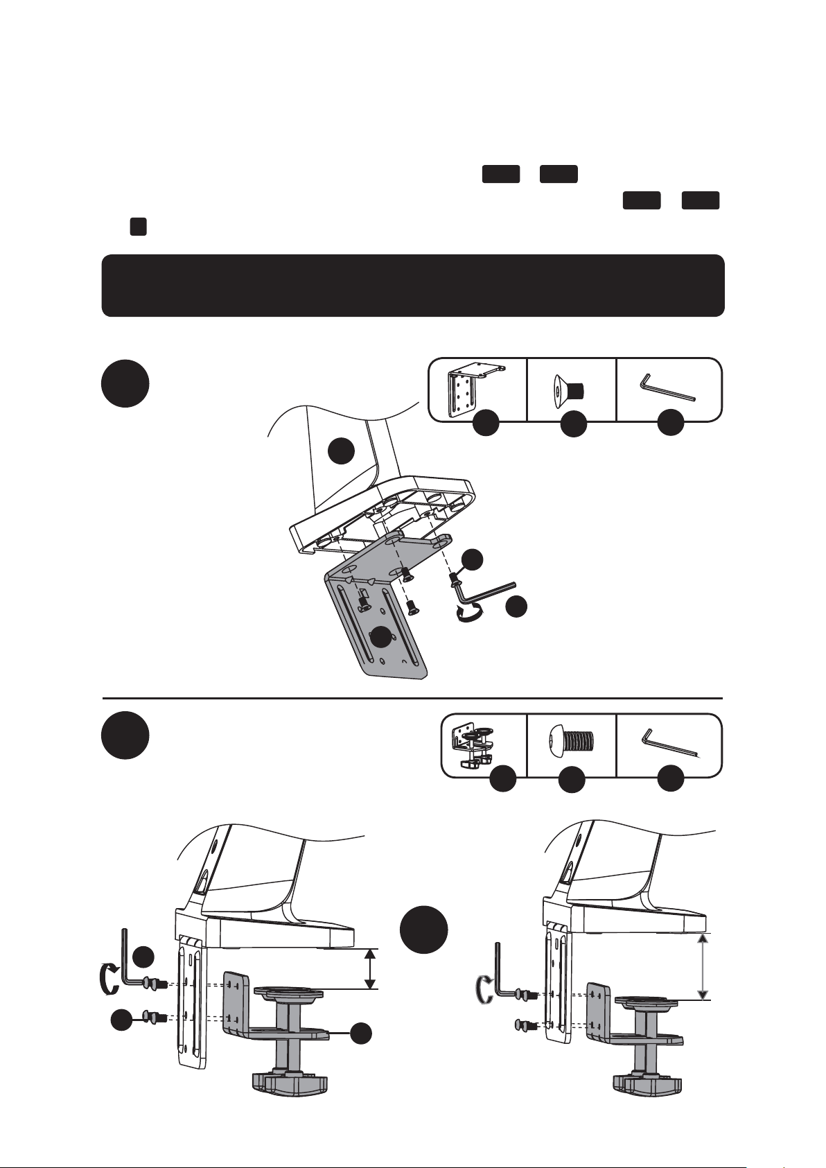
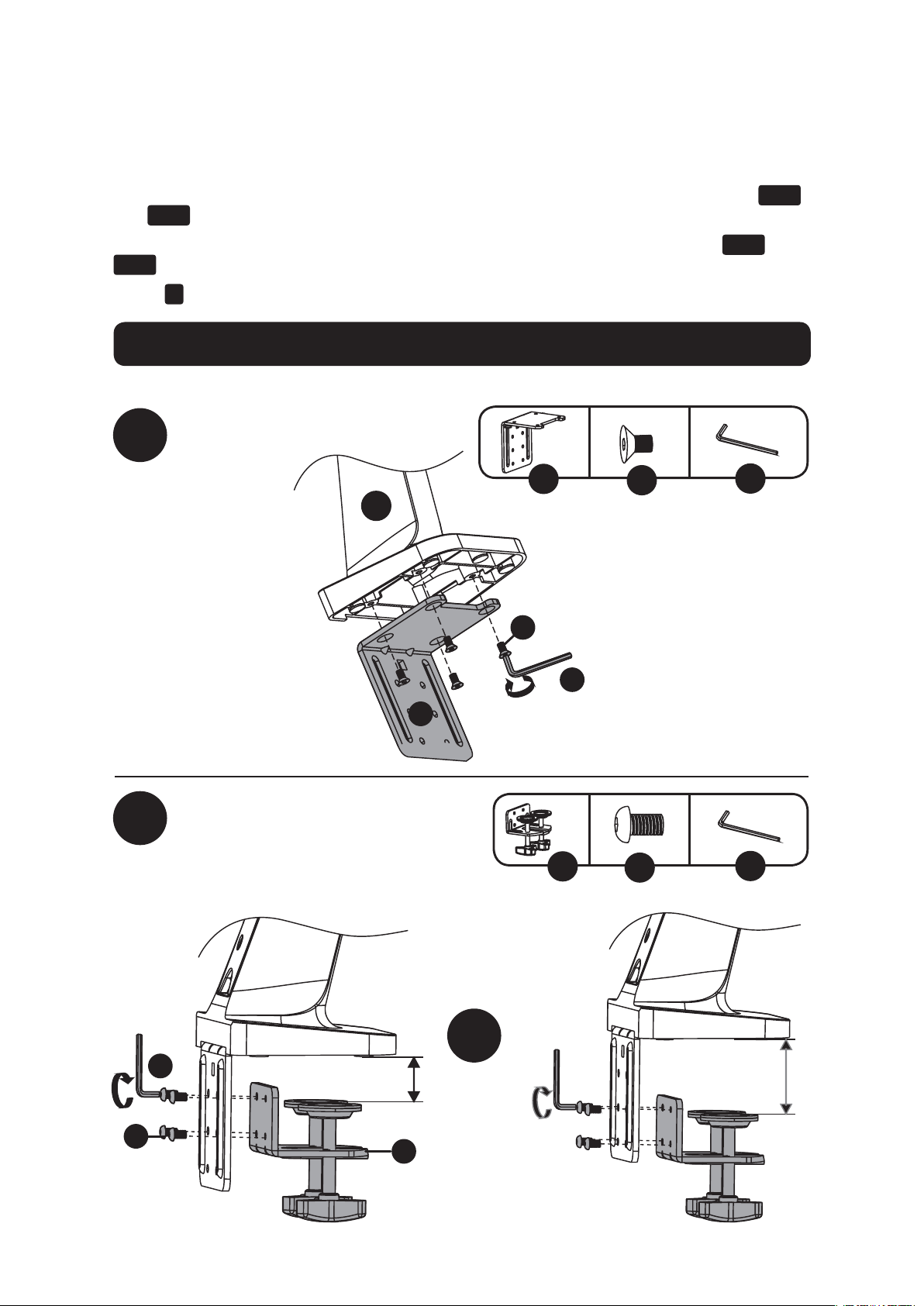
Desk Clamp Assembly Option
1a-1
1a-2
or
Note: For instructions on Grommet Mount Assembly, go to page 5.
D
E
U
U
J
K
x4
x4
U
D
J
A
E
K
U
3/8 to 2”
(10 to 55 mm)
1 1/2 to 3 9/16”
(40 to 92 mm)
The WWSS1332C Single-Display Sit-Stand Workstation offers two different mounting methods:
by desk clamp or by grommet mount. For easy and convenient installation and removal, use the
desk clamp mounting option. For a permanent mounting solution, use the grommet mounting
option.
Desk Clamp Assembly – Follow steps
1a-1
to
1a-4
below.
Grommet Mount – Go to page 5 and follow steps
1b-1
to
1b-2
.
Step
2
for both mounting options begins on page 6.

4
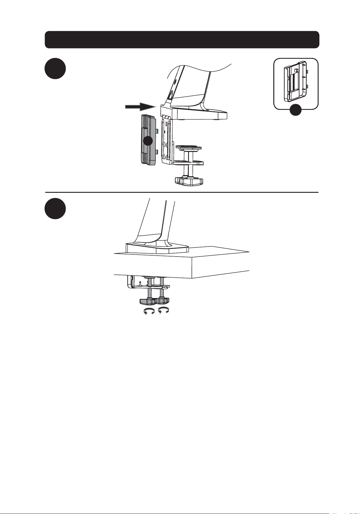
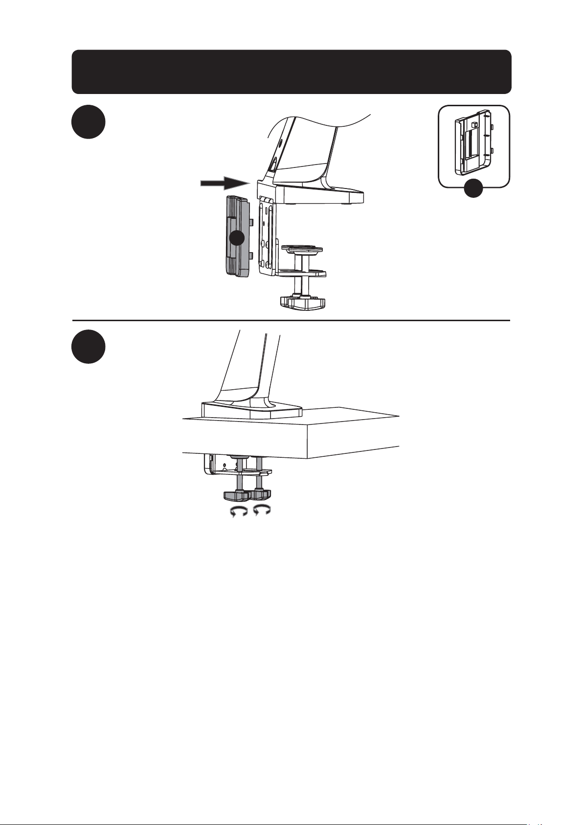
Desk Clamp Assembly Option
1a-3
1a-4
F
F
To proceed with step 2 of assembly, go to page 6.

5
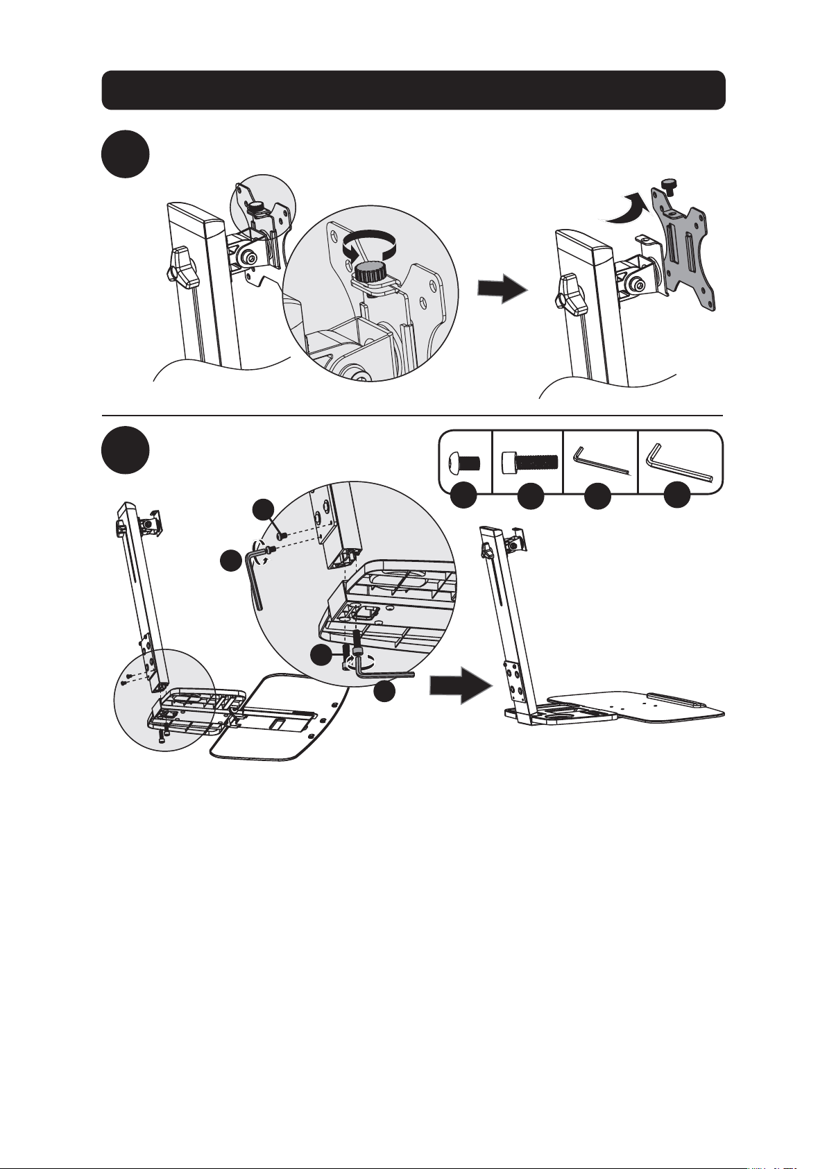
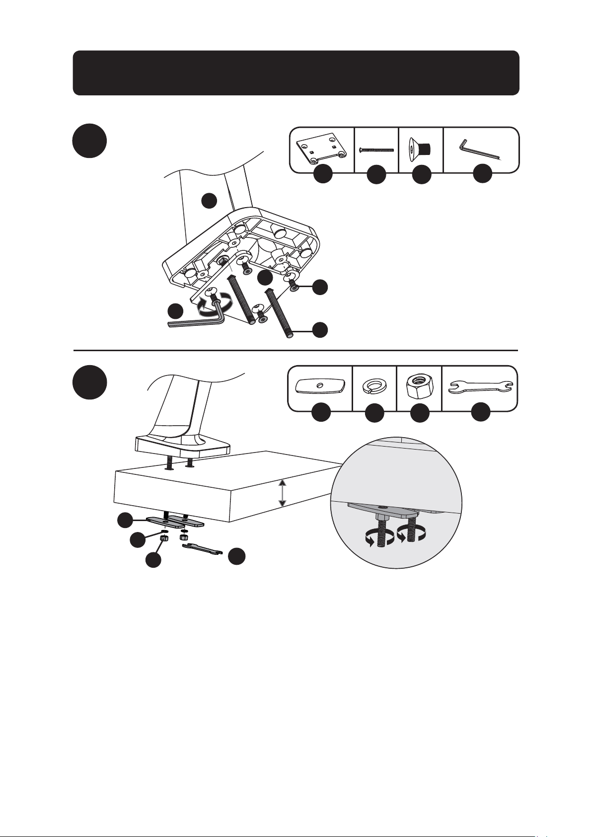
Grommet Mount Assembly Option
1b-2
1b-1
G
U
JI
x4x2
H
W
TR
x2 x2 x2
A
U
J
G
I
W
H
R
T
3/8 to 3”
(10 to 80 mm)
To proceed with step 2 of assembly, go to page 6.
Note: For instructions on Clamp Assembly, go to page 3.
6
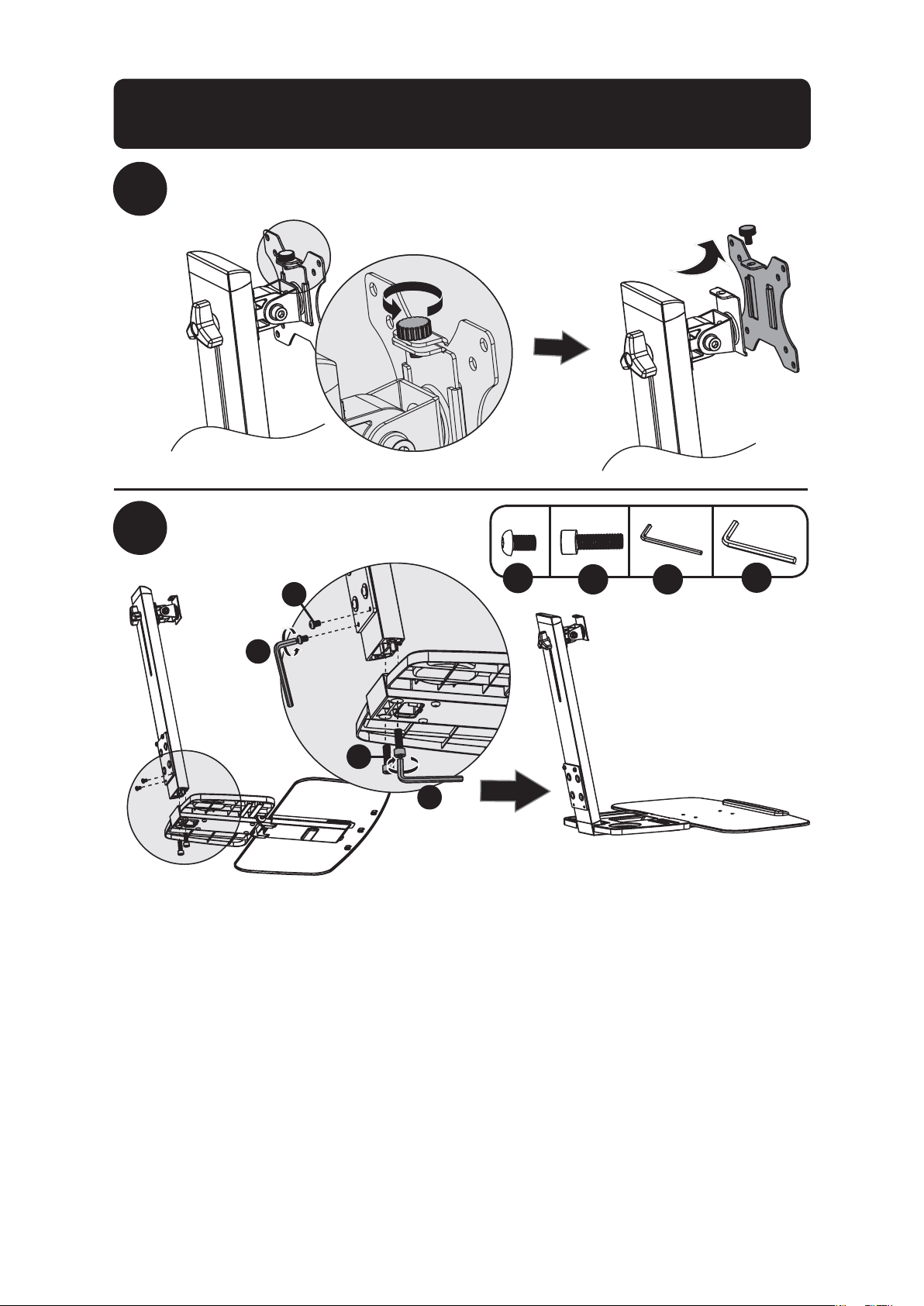
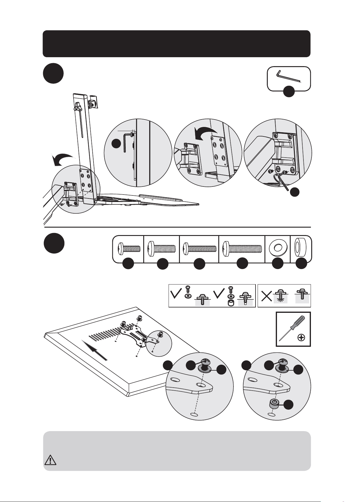
2
3
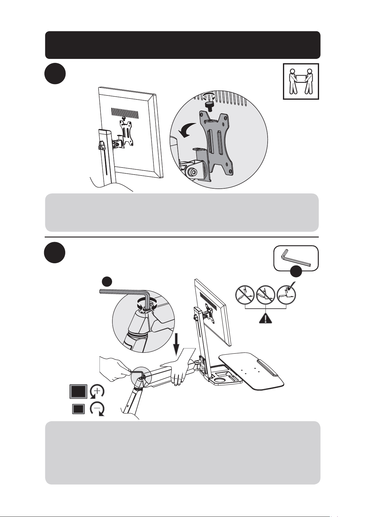
Remove VESA Plate from Support Mast
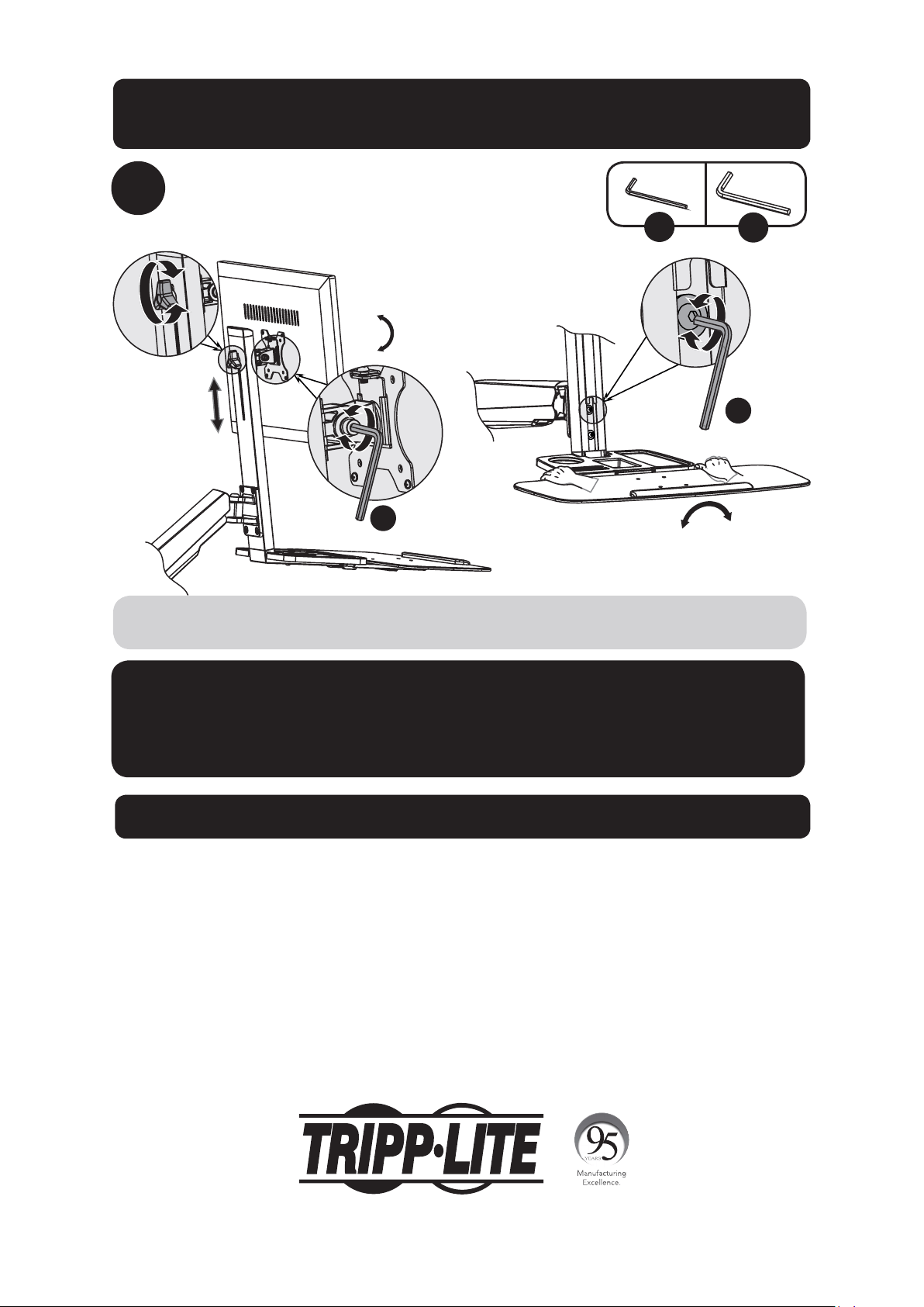
Attach Keyboard Shelf
to Support Mast
K
V
UL
x2 x2
U
V
K
L
Desk Clamp/Grommet Mount Assembly
7
Desk Clamp/Grommet Mount Assembly
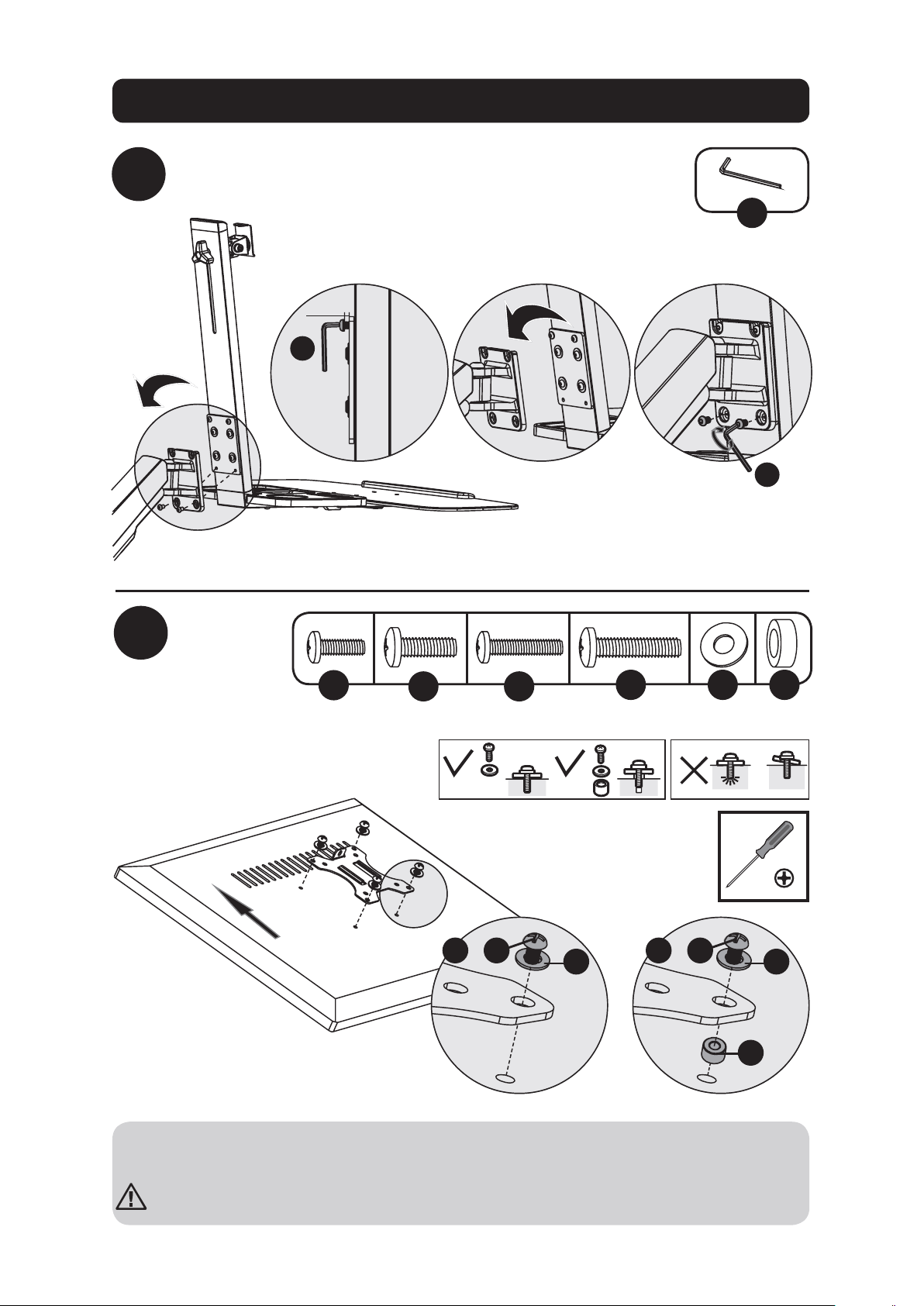
4
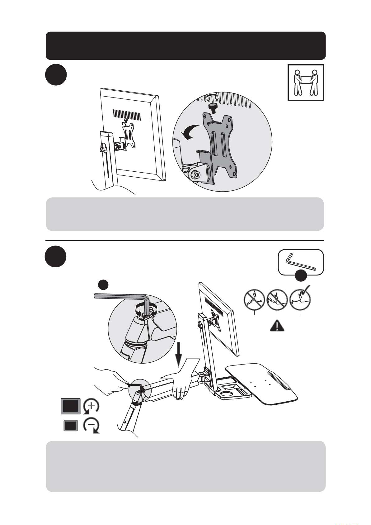
Attach Keyboard Shelf and Support
Mast Assembly to Bracket Arm
Attach
VESA
plate to
back of
display
U
U
U
3/16” (5 mm)
5
TV
TV
TV
TV
M
P Q S
ON
x4 x4 x4 x4x4x4
M
ON
Q Q
S
P
or or
Note: Firmly secure the VESA plate to the display using the appropriate screws, washers and
spacers (if necessary).
Do not over-tighten screws.
8
Desk Clamp/Grommet Mount Assembly
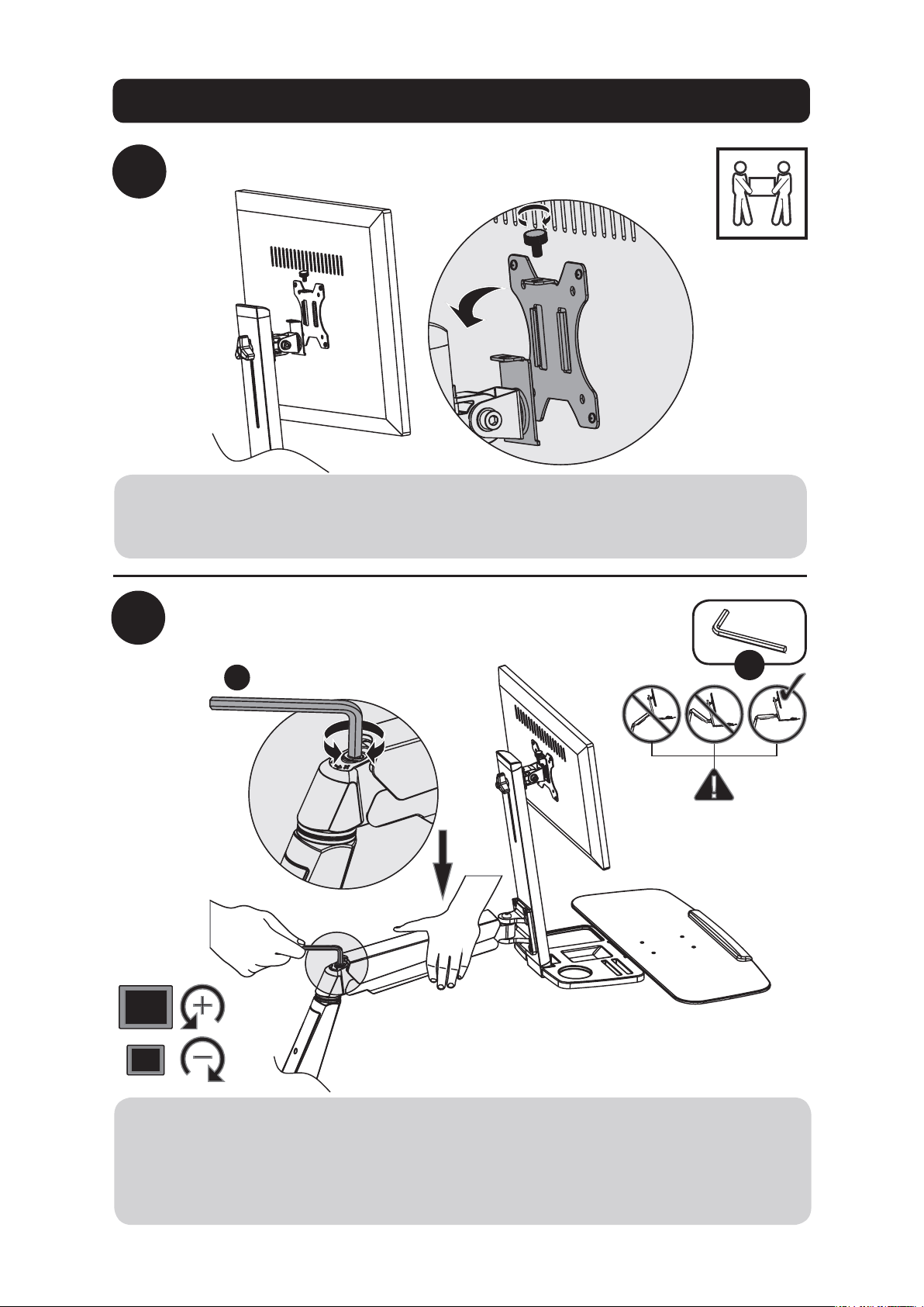
6
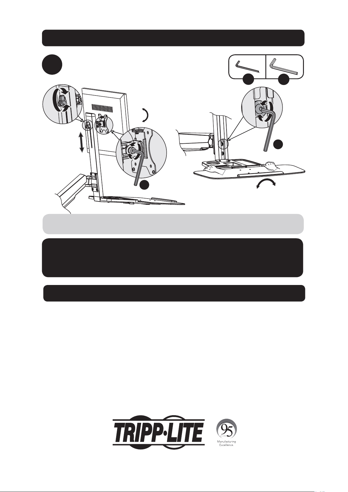
Slide VESA plate and Display on to the Support Mast
Adjust Bracket Arm tension
V
7
V
Using an assistant or mechanical lifting equipment, lift the display with attached VESA plate.
Slide the VESA plate over the Support Mast bracket. Reattach the top knob to secure the VESA
mount (removed in step 1).
Keep the bracket arm level during tension adjustment. You may need to slightly loosen or tight-
en the adjustment screw using the provided 6 mm Hex Key, depending on the weight of display
installed.
If display settles on its own, rotate adjustment screw towards the “+” symbol.
If display rises on its own, rotate adjustment screw towards the “-” symbol.
9
Desk Clamp/Grommet Mount Assembly
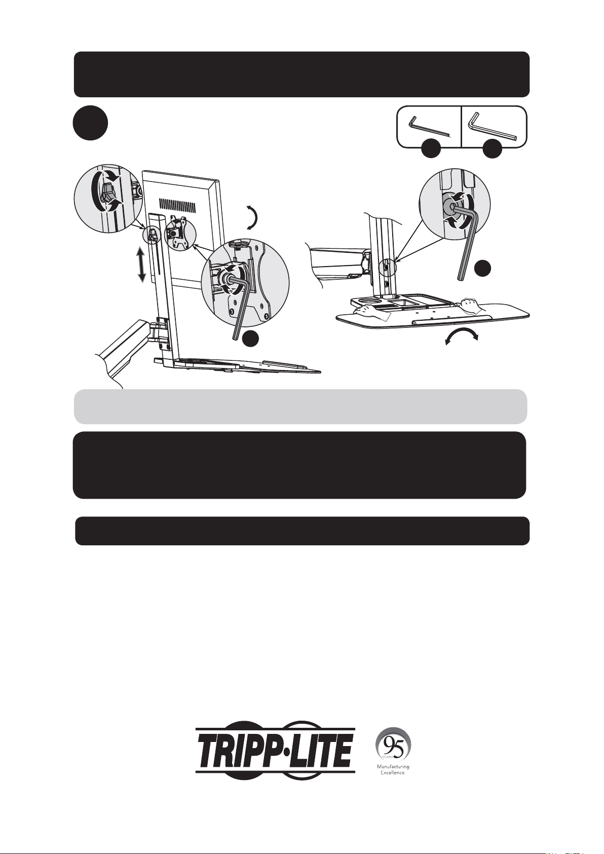
8
Adjust to the desired location or tilt
+4°
-
4
°
+15°
-15°
U
V
To correct the tilting angle, tighten the adjustment screws using the provided Hex Keys (or
tighten the knob).
Maintenance
• Check that the bracket is secure and safe to use at regular intervals
(at least every three months).
• Please visit www.tripplite.com/support if you have any questions.
V
U
Warranty and Product Registration
5-Year Limited Warranty
Seller warrants this product, if used in accordance with all applicable instructions, to be free from original defects in material and workmanship for a period
of 5 years from the date of initial purchase. If the product should prove defective in material or workmanship within that period, Seller will repair or replace
the product, in its sole discretion.
THIS WARRANTY DOES NOT APPLY TO NORMAL WEAR OR TO DAMAGE RESULTING FROM ACCIDENT, MISUSE, ABUSE OR NEGLECT. SELLER MAKES NO
EXPRESS WARRANTIES OTHER THAN THE WARRANTY EXPRESSLY SET FORTH HEREIN. EXCEPT TO THE EXTENT PROHIBITED BY APPLICABLE LAW, ALL
IMPLIED WARRANTIES, INCLUDING ALL WARRANTIES OF MERCHANTABILITY OR FITNESS, ARE LIMITED IN DURATION TO THE WARRANTY PERIOD SET FORTH
ABOVE; AND THIS WARRANTY EXPRESSLY EXCLUDES ALL INCIDENTAL AND CONSEQUENTIAL DAMAGES. (Some states do not allow limitations on how
long an implied warranty lasts, and some states do not allow the exclusion or limitation of incidental or consequential damages, so the above limitations or
exclusions may not apply to you. This warranty gives you specific legal rights, and you may have other rights which vary from jurisdiction to jurisdiction).
WARNING: The individual user should take care to determine prior to use whether this device is suitable, adequate or safe for the use intended. Since
individual applications are subject to great variation, the manufacturer makes no representation or warranty as to the suitability or fitness of these devices
for any specific application.
PRODUCT REGISTRATION
Visit www.tripplite.com/warranty today to register your new Tripp Lite product. You’ll be automatically entered into a drawing for a chance to win a FREE
Tripp Lite product!* * No purchase necessary. Void where prohibited. Some restrictions apply. See website for details.
Tripp Lite has a policy of continuous improvement. Specifications are subject to change without notice.
1111 W. 35th Street, Chicago, IL 60609 USA • www.tripplite.com/support
10
Manual del Propietario
Estación de Trabajo de
Altura Variable para Una
Pantalla para Instalación
en Escritorio
Modelo: WWSS1332C
1111 W. 35th Street, Chicago, IL 60609 USA • www.tripplite.com/support
Copyright © 2017 Tripp Lite. Todos los derechos reservados.
PRECAUCIÓN: NO EXCEDA LA CAPACIDAD MÁXIMA DE CARGA INDICADA (8 kg).
¡PUEDE OCURRIR UNA LESIÓN SEVERA O DAÑO A LA PROPIEDAD!
English 1 • Français 19 •
Русский
28 • Deutsch 37
11
Lista de Comprobación de Componentes
IMPORTANTE: Asegúrese antes de instalar, de haber recibido todas las partes de
acuerdo a la lista de comprobación de componentes. Si faltase cualquier parte o
estuviese dañada, visite www.tripplite.com/support para solicitar servicio.
A
F
K
P
U
B
G
L
Q
D
I
N
S
E
J
O
T
W
C
H
M
R
V
Brazo de
Soporte
x1
Abrazadera de
Cable
x1
M6 x 12
x4
M5 x 16
x4
Llave
Hexagonal de
4 mm
x1
Mástil de
Soporte
x1
Placa para
Instalación con
Orificio Pasa Cables
x1
M8 x 25
x2
5 x 12 x 1
x4
Repisa para
Teclado
x1
Placa de
Presión
x2
M4 x 12
x4
D8
x2
Llave
Hexagonal de
6 mm
x1
Parte
Superior de la
Abrazadera
x1
M8 x 105
x2
M5 x 12
x4
Espaciador de
8 x 5
x4
Parte
Inferior de la
Abrazadera
x1
M6 x 10
x4
M4 x 16
x4
M8
x2
Llave
x1
12
Opción con Abrazadera de Escritorio
1a-1
1a-2
o
Nota: Para instrucciones sobre la instalación por Orificio Pasa Cables, vaya a la página 14.
D
E
U
U
J
K
x4
x4
U
D
J
A
E
K
U
10 a 55 mm
40 a 92 mm
La Estación de Trabajo de Altura Variable para Una Pantalla WWSS1332C ofrece dos diferentes
métodos de instalación: por abrazadera de escritorio o por Orificio Pasa Cables. Para instalación
y remoción fácil y cómoda, use la opción de instalación con abrazadera de escritorio. Para una
solución de instalación permanente, use la opción de instalación por Orificio Pasa Cables.
Ensamble con Abrazadera de Escritorio – Siga los pasos
1a-1
a
1a-4
siguientes.
Instalación por Orificio Pasa Cables – Vaya a la página X y siga los pasos
1b-1
a
1b-2
.
Paso
2
para ambas opciones de instalación inicie en la página 15.
13
Opción con Abrazadera de Escritorio
1a-3
1a-4
F
F
Para proceder con el paso 2 del ensamble, vaya a la página 15.

14
Opción de Instalación por Orificio Pasa Cables
1b-2
1b-1
G
U
JI
x4x2
H
W
TR
x2 x2 x2
A
U
J
G
I
W
H
R
T
10 a 88 mm
Para proceder con el paso 2 del ensamble, vaya a la página15.
Nota: Para instrucciones sobre la instalación por abrazadera, vaya a la página 12.

15
2
3
Retire la Placa VESA del Mástil de Soporte
Coloque la Repisa para Teclado
en el Mástil de Soporte
K
V
UL
x2 x2
U
V
K
L
Conjunto de Instalación por Orificio Pasa Cables /
Abrazadera de Escritorio

16
Conjunto de Instalación por Orificio Pasa Cables /
Abrazadera de Escritorio
4
Coloque el Conjunto de la Repisa para Teclado y el
Mástil de Soporte en el Brazo de Soporte
Coloque
la placa
VESA a
la parte
posterior
de la
pantalla
U
U
U
5 mm
5
TV
TV
TV
TV
M
P Q S
ON
x4 x4 x4 x4x4x4
M
ON
Q Q
S
P
o o
Nota: Asegure firmemente la placa VESA a la pantalla usando los tornillos, arandelas y espa-
ciadores apropiados (si fuera necesario).
No apriete excesivamente los tornillos.

17
6
Deslice la placa VESA y la Pantalla en el
Mástil de Soporte
Ajuste la tensión del Brazo de Soporte
V
7
V
Usando un ayudante o equipo de elevación mecánico, levante la pantalla con la placa VESA
acoplada. Deslice la placa VESA sobre la Ménsula del Mástil de Soporte. Reinstale la perilla
superior para sujetar el soporte VESA (retirados en el paso 1).
Mantenga nivelado el brazo del soporte de pared durante el ajuste de la tensión. Puede
necesitar apretar o aflojar ligeramente el tornillo de ajuste con la llave hexagonal de 6 mm
suministrada, dependiendo del peso de la pantalla instalada.
Si la pantalla se baja por sí misma, gire el tornillo de ajuste hacia el símbolo “+”.
Si la pantalla se levanta por sí misma, gire el tornillo de ajuste hacia el símbolo “-”.
Conjunto de Instalación por Orificio Pasa Cables /
Abrazadera de Escritorio

18
8
Ajuste a la posición o inclinación deseada
+4°
-
4
°
+15°
-15°
U
V
Para corregir el ángulo de inclinación, apriete el tornillo de ajuste usando las llaves
hexagonales suministradas (o apriete la perilla).
Mantenimiento
• Compruebe a intervalos regulares
(al menos cada tres meses) que el soporte esté seguro para usarse.
• Si tiene alguna pregunta, visite por favor a www.tripplite.com/support.
V
U
Garantía
Garantía Limitada por 5 Años
El vendedor garantiza este producto, si se usa de acuerdo con todas las instrucciones aplicables, de que está libre de defectos en material y mano de obra
por un período de 5 años a partir de la fecha de compra inicial. Si el producto prueba ser defectuoso en material o mano de obra dentro de ese período, el
vendedor reparará o reemplazará el producto a su entera discreción.
ESTA GARANTÍA NO APLICA AL DESGASTE NORMAL O A DAÑOS RESULTANTES DE ACCIDENTES, MAL USO, ABUSO O NEGLIGENCIA. EL VENDEDOR
NO OTORGA GARANTÍAS EXPRESAS DISTINTAS DE LA ESTIPULADA AQUÍ. EXCEPTO A LA EXTENSIÓN PROHIBIDA POR LA LEY APLICABLE, TODAS LAS
GARANTÍAS IMPLÍCITAS, INCLUYENDO TODAS LAS GARANTÍAS DE COMERCIALIZACIÓN O IDONEIDAD, ESTÁN LIMITADAS EN DURACIÓN AL PERÍODO DE
GARANTÍA ESTABLECIDO; Y ESTA GARANTÍA EXCLUYE EXPRESAMENTE TODOS LOS DAÑOS INCIDENTALES Y CONSECUENCIALES. (Algunos estados no
permiten limitaciones en cuanto al período de duración de una garantía y algunos estados no permiten la exclusión de limitación de daños incidentales o
consecuenciales, de modo que las limitaciones anteriores pueden no aplicar para usted. Esta garantía le otorga derechos legales específicos y usted puede
tener otros derechos que pueden variar de una jurisdicción a otra).
IMPORTANTE: Asegúrese antes de instalar, de haber recibido todas las partes de acuerdo a la lista de comprobación de componentes. Si faltase cualquier
parte o estuviese dañada, visite www.tripplite.com/support para solicitar servicio.
Tripp Lite tiene una política de mejora continua. Las especificaciones están sujetas a cambio sin previo aviso.
1111 W. 35th Street, Chicago, IL 60609 USA • www.tripplite.com/support
Conjunto de Instalación por Orificio Pasa Cables /
Abrazadera de Escritorio
19
Manuel de l’utilisateur
Station de travail à
montage sur bureau assis-
debout à un seul écran
Modèle : WWSS1332C
1111 W. 35th Street, Chicago, IL 60609 USA • www.tripplite.com/support
Droits d’auteur © 2017 Tripp Lite. Tous droits réservés.
MISE EN GARDE : NE PAS EXCÉDER LA CAPACITÉ PONDÉRALE MAXIMUM
INDIQUÉE (8 kg). DES BLESSURES GRAVES OU DES DOMMAGES MATÉRIELS
RISQUENT DE SE PRODUIRE!
English 1 • Español 10 •
Русский
28 • Deutsch 37
20
Liste de vérification des composants
IMPORTANT : Veuillez vous assurer d’avoir reçu toutes les pièces conformément
à la liste de vérification des composants avant de procéder à l’installation. Si des
pièces sont manquantes ou défectueuses, visitez www.tripplite.com/support pour
obtenir de l’aide.
A
F
K
P
U
B
G
L
Q
D
I
N
S
E
J
O
T
W
C
H
M
R
V
Bras du
support
x1
Bride de câble
x1
M6 x 12
x4
M5 x 16
x4
Clé hexagonale
de 4 mm
x1
Mât de support
x1
Plaque de montage
passe-fils
x1
M8 x 25
x2
5 x 12 x 1
x4
Étagère du
clavier
x1
Plaque de
pression
x2
M4 x 12
x4
D8
x2
Clé hexagonale
de 6 mm
x1
Bride
supérieure
x1
M8 x 105
x2
M5 x 12
x4
Entretoise
8 x 5
x4
Bride inférieure
x1
M6 x 10
x4
M4 x 16
x4
M8
x2
Clé
x1
21
Option d’assemblage avec bride pour bureau
1a-1
1a-2
ou
Remarque : Pour des instructions sur l’assemblage par montage passe-fils, aller à la page 23.
D
E
U
U
J
K
x4
x4
U
D
J
A
E
K
U
10 à 55 mm
40 à 92 mm
La station de travail assis-debout à un seul écran WWSS1332C offre deux méthodes de montage
différentes : par bride pour bureau ou par montage passe-fils. Pour une installation et un retrait
simples et pratiques, utiliser l’option de montage par bride pour bureau. Pour une solution de
montage permanente, utiliser l’option de montage passe-fils.
Ensemble de la bride pour bureau – Suivre les étapes
1a-1
à
1a-4
ci-dessous.
Montage passe-fils – Aller à la page X et suivre les étapes
1b-1
à
1b-2
.
L’étape
2
pour les deux options de montage commence à la page 24.

22
Option d’assemblage avec bride pour bureau
1a-3
1a-4
F
F
Pour passer à l’étape 2 de l’assemblage, aller à la page 24.
23
Option d’assemblage par montage passe-fils
1b-2
1b-1
G
U
JI
x4x2
H
W
TR
x2 x2 x2
A
U
J
G
I
W
H
R
T
10 à 88 mm
Pour passer à l’étape 2 de l’assemblage, aller à la page 24.
Remarque : Pour des instructions sur l’assemblage par bride, aller à la page 21.
24
2
3
Retirer la plaque VESA du mât du support
Fixer l’étagère du clavier au
mât de support
K
V
UL
x2 x2
U
V
K
L
Assemblage avec bride pour bureau/
montage passe-fils

25
Assemblage avec bride pour bureau/
montage passe-fils
4
Fixer l’étagère du clavier et l’ensemble du mât de
support au bras de support
Fixer la
plaque
VESA à
l’arrière
de l’écran
U
U
U
5 mm
5
TV
TV
TV
TV
M
P Q S
ON
x4 x4 x4 x4x4x4
M
ON
Q Q
S
P
ou ou
Remarque : Attacher fermement la plaque VESA à l’écran en utilisant les vis, les rondelles et
les entretoises (au besoin).
Ne pas trop serrer les vis.
26
6
Glisser la plaque VESA et l’écran sur le
mât de support
Régler la tension du bras de support
V
7
V
Faire appel à un assistant ou utiliser de l’équipement de levage mécanique pour soulever
l’écran avec la plaque VESA déjà en place. Glisser la plaque VESA sur le support de mât de
support. Rattacher le bouton supérieur pour sécuriser le montage VESA (retiré à l’étape 1).
Garder le bras de montage mural au niveau durant le réglage de la tension. Il peut s’avérer
nécessaire de desserrer ou de serrer légèrement la vis de réglage en utilisant la clé hexagonale
de 6 mm fournie en fonction du poids de l’écran installé
Si l’écran s’abaisse de lui-même, tourner la vis de réglage vers le symbole « + ».
Si l’écran monte de lui-même, tourner la vis de réglage vers le symbole « - ».
Assemblage avec bride pour bureau/
montage passe-fils
27
8
Régler à l’endroit et selon l’angle désirés
+4°
-
4
°
+15°
-15°
U
V
Pour corriger l’angle d’inclinaison, serrer la vis de réglage au moyen des clés hexagonales
fournies (ou serrer le bouton).
Entretien
• Vérifier à intervalles réguliers que le support peut être utilisé de façon sûre et sécuritaire
(au moins tous les trois mois).
• Veuillez visiter www.tripplite.com/support si vous avez des questions.
V
U
Garantie
Garantie limitée de 5 ans
Le vendeur garantit que ce produit, s’il est utilisé conformément à toutes les instructions applicables, est exempt de tous défauts de matériaux et de
fabrication pour une période de 5 ans à partir de la date d’achat initiale. Si le produit s’avère défectueux en raison d’un vice de matière ou de fabrication au
cours de cette période, le vendeur s’engage à réparer ou remplacer le produit, à sa seule discrétion.
CETTE GARANTIE NE S’APPLIQUE PAS À L’USURE NORMALE OU AUX DOMMAGES RÉSULTANT D’UN ACCIDENT, D’UNE MAUVAISE UTILISATION, D’UN ABUS
OU D’UNE NÉGLIGENCE. LE VENDEUR NE DONNE AUCUNE GARANTIE EXPRESSE AUTRE QUE LA GARANTIE EXPRESSÉMENT DÉCRITE DANS LE PRÉSENT
DOCUMENT. SAUF DANS LA MESURE INTERDITE PAR LA LOI APPLICABLE, TOUTE GARANTIE IMPLICITE, Y COMPRIS TOUTES LES GARANTIES DE QUALITÉ
MARCHANDE OU D’ADAPTATION, SONT LIMITÉES À LA PÉRIODE DE GARANTIE CI-DESSUS ET CETTE GARANTIE EXCLUT EXPRESSÉMENT TOUS DOMMAGES
DIRECTS ET INDIRECTS. (Certains États ne permettent pas de limitations sur la durée d’une garantie implicite, et certains États ne permettent pas
l’exclusion ou la limitation des dommages fortuits ou consécutifs, de sorte que les limitations ou exclusions susmentionnées peuvent ne pas s’appliquer à
vous. Cette garantie vous donne des droits légaux spécifiques, et vous pouvez avoir d’autres droits qui varient selon la juridiction).
AVERTISSEMENT : L’utilisateur individuel doit prendre soin de déterminer avant l’utilisation si cet appareil est approprié, adéquat et sûr pour l’usage prévu.
Puisque les utilisations individuelles sont sujettes à des variations importantes, le fabricant ne fait aucune déclaration ou garantie quant à l’aptitude ou
l’adaptation de ces dispositifs pour une application spécifique.
La politique de Tripp Lite en est une d’amélioration continue. Les spécifications sont sujettes à changement sans préavis.
1111 W. 35th Street, Chicago, IL 60609 USA • www.tripplite.com/support
Assemblage avec bride pour bureau/
montage passe-fils

28
Руководствопользователя
Настольнаярабочая
станциясрегулируемой
высотойнаодиндисплей
МОДЕЛЬ:WWSS1332C
1111 W. 35th Street, Chicago, IL 60609 USA • www.tripplite.com/support
Охраняетсяавторскимправом©2017TrippLite.Перепечатказапрещается.
ВНИМАНИЕ!НЕПРЕВЫШАЙТЕМАКСИМАЛЬНОДОПУСТИМЫЙВЕС(8кг).
ЭТОМОЖЕТПРИЧИНИТЬСУЩЕСТВЕННЫЙВРЕДЗДОРОВЬЮЛЮДЕЙИЛИ
МАТЕРИАЛЬНЫЙУЩЕРБ!
English 1 • Español 10 • Français 19 • Deutsch 37
29
Переченькомплектации
ВНИМАНИЕ!Передначаломустановкиубедитесьвтом,чтовамиполученывсе
деталисогласноперечнюкомплектации.Вслучаеотсутствияилиповреждения
каких-либодеталейобратитесьзапомощьюнастраницуwww.tripplite.com/support.s
sontmanquantesoudéfectueuses,visitezwww.tripplite.com/supportpourobtenirde
l’aide.
A
F
K
P
U
B
G
L
Q
D
I
N
S
E
J
O
T
W
C
H
M
R
V
Рычаг
кронштейна
1шт.
Зажимдля
крепления
кабеля
1шт.
M6x12
x4
M5x16
4шт.
Шестигранный
ключна4мм
1шт.
Опора
1шт.
Монтажнаяпластинас
изолирующейвтулкой
1шт.
M8x25
2шт.
5x12x1
4шт.
Полкадля
клавиатуры
1шт.
Прижимная
пластина
2шт.
M4x12
4шт.
D8
2шт.
Шестигранный
ключна6мм
1шт.
Верхний
элемент
зажима
1шт.
M8x105
2шт.
M5x12
4шт.
Проставка8x5
4шт.
Нижний
элемент
зажима
1шт.
M6x10
4шт.
M4x16
4шт.
M8
2шт.
Гаечныйключ
1шт.
30
Вариантмонтажасиспользованиемсборного
зажимадлякреплениякстолу
1a-1
1a-2
или
Примечание.Указанияпосборкекронштейнасизолирующейвтулкойсм.настр.32.
D
E
U
U
J
K
4шт.
4шт.
U
D
J
A
E
K
U
10до55мм
40до92мм
Рабочаястанциясрегулируемойвысотойнаодиндисплей(мод.WWSS1332C)предполагает
дваразличныхтипамонтажа:спомощьюзажимадлякреплениякстолуиликронштейнас
изолирующейвтулкой.Дляпростотыиудобстваустановкииснятияиспользуйтевариантс
зажимомдлякреплениякстолу.Длямонтажанадлительноевремябезснятияиспользуйте
вариантсизолирующейвтулкой.
Сборныйзажимдлякреплениякстолу:выполнитедействия
1a-1
―
1a-4
,представленныениже.
Кронштейнсизолирующейвтулкой:перейдитенастр.Xивыполнитедействия
1b-1
―
1b-2
.
Шаг
2
дляобоихвариантовмонтажаначинаетсянастр.33.
31
Вариантмонтажасиспользованиемсборного
зажимадлякреплениякстолу
1a-3
1a-4
F
F
Длявыполненияшага2процессасборкиперейдитенастр.33.
32
Вариантмонтажасиспользованиемсборного
кронштейнасизолирующейвтулкой
1b-2
1b-1
G
U
JI
4шт.2шт.
2шт. 2шт. 2шт.
H
W
TR
A
U
J
G
I
W
H
R
T
10до88мм
Длявыполненияшага2процессасборкиперейдитенастр.33.
Примечание.Указанияпосборкезажимасм.настр.30.

33
2
3
ОтсоединитепластинуVESAотопоры
Прикрепитеполкудля
клавиатурыкопоре
K
V
UL
U
V
K
L
Сборказажимадлякреплениякстолу/
кронштейнасизолирующейвтулкой
2шт.
2шт.

34
Сборказажимадлякреплениякстолу/
кронштейнасизолирующейвтулкой
4
Прикрепитеполкудляклавиатурысопоройкрычагу
кронштейна
Прикрепите
пластину
VESAк
задней
панели
дисплея
U
U
U
5мм
5
TV
TV
TV
TV
M
P Q S
ON
M
ON
Q Q
S
P
или или
Примечание.ПлотноприкрепитепластинуVESAкдисплеюсиспользованиемсоответствующих
винтов,шайбираспорок(принеобходимости).
Неперетягивайтевинты.
4шт. 4шт. 4шт. 4шт. 4шт. 4шт.
35
6
НаденьтепластинуVESAсдисплеемнаопору
Отрегулируйтеусилиезатяжкирычагакронштейна
V
7
V
Обратившисьзапомощьюиливоспользовавшисьмеханическимподъемнымоборудованием,
поднимитедисплейсприкрепленнойкнемупластинойVESAНаденьтепластинуVESAповерх
держателяопоры.Завернитеверхнююрегулировочнуюголовку(вывернутуюнашаге6)для
фиксациикронштейнаVESA.
Впроцессерегулировкизатяжкисохраняйтеуровеньрасположениякронштейна.Припомощи
торцевогоключасоответствующегоразмераслегкаослабьтеилизатянитерегулировочныйвинт
взависимостиотвесадисплея.
Вслучаесамопроизвольногоопусканиядисплеяповернитерегулировочныйвинтпо
направлениюкзначку“+”.
Вслучаесамопроизвольногоподнятиядисплеяповернитерегулировочныйвинтпо
направлениюкзначку“-”.
Сборказажимадлякреплениякстолу/
кронштейнасизолирующейвтулкой
36
8
Установитевнужноеположениеилипод
нужнымуглом
+4°
-
4
°
+15°
-15°
U
V
Длякорректировкиугланаклоназатянитерегулировочныевинтыспомощьюшестигранных
ключей,поставляемыхвкомплекте(илизатянитерегулировочнуюголовку).
Техническоеобслуживание
•Регулярно(нереже,чемразвтримесяца)проверяйтенадежностькреплениякронштейнаи
безопасностьегоиспользования.
•Вслучаевозникновениякаких-либовопросовприглашаемваспосетитьстраницу
www.tripplite.com/support.
V
U
Гарантийныеобязательства
Условия5-летнейограниченнойгарантии
родавецгарантируетотсутствиеизначальныхдефектовматериалаилиизготовлениявтечение5летсмоментапервойпокупкиданногоизделияприусловии
егоиспользованиявсоответствиисовсемиприменимымикнемууказаниями.Вслучаепроявлениякаких-либодефектовматериалаилиизготовленияв
течениеуказанногопериодаПродавецосуществляетремонтилизаменуданногоизделияисключительнопосвоемуусмотрению.
ДЕЙСТВИЕНАСТОЯЩЕЙГАРАНТИИНЕРАСПРОСТРАНЯЕТСЯНАСЛУЧАИЕСТЕСТВЕННОГОИЗНОСАИЛИПОВРЕЖДЕНИЯВРЕЗУЛЬТАТЕАВАРИИ,
НЕНАДЛЕЖАЩЕГОИСПОЛЬЗОВАНИЯ,НАРУШЕНИЯПРАВИЛЭКСПЛУАТАЦИИИЛИХАЛАТНОСТИ.ПРОДАВЕЦНЕПРЕДОСТАВЛЯЕТНИКАКИХЯВНО
ВЫРАЖЕННЫХГАРАНТИЙЗАИСКЛЮЧЕНИЕМПРЯМОИЗЛОЖЕННОЙВНАСТОЯЩЕМДОКУМЕНТЕ.ЗАИСКЛЮЧЕНИЕМСЛУЧАЕВ,ЗАПРЕЩЕННЫХ
ДЕЙСТВУЮЩИМЗАКОНОДАТЕЛЬСТВОМ,ВСЕПОДРАЗУМЕВАЕМЫЕГАРАНТИИ,ВКЛЮЧАЯВСЕГАРАНТИИПРИГОДНОСТИДЛЯПРОДАЖИИЛИ
ИСПОЛЬЗОВАНИЯПОНАЗНАЧЕНИЮ,ОГРАНИЧЕНЫПОПРОДОЛЖИТЕЛЬНОСТИДЕЙСТВИЯВЫШЕУКАЗАННЫМГАРАНТИЙНЫМСРОКОМ;КРОМЕ
ТОГО,ИЗНАСТОЯЩЕЙГАРАНТИИЯВНЫМОБРАЗОМИСКЛЮЧАЮТСЯВСЕПОБОЧНЫЕ,СЛУЧАЙНЫЕИКОСВЕННЫЕУБЫТКИ.(Внекоторыхштатахне
допускаетсявведениеограниченийнапродолжительностьдействиятехилииныхподразумеваемыхгарантий,авнекоторых-исключениеилиограничение
размерапобочныхиликосвенныхубытков.Вэтихслучаяхвышеизложенныеограниченияилиисключениямогутнаваснераспространяться.Настоящая
гарантияпредоставляетвамконкретныеюридическиеправа,анабордругихвашихправможетбытьразличнымвзависимостиотюрисдикции).
ВНИМАНИЕ!Доначалаиспользованияданногоустройствапользовательдолженубедитьсявтом,чтооноявляетсяпригодным,соответствующимили
безопаснымдляпредполагаемогоприменения.Всвязисбольшимразнообразиемконкретныхпримененийпроизводительнедаеткаких-либозаверенийили
гарантийотносительнопригодностиданныхизделийдлякакого-либоконкретногопримененияилиихсоответствиякаким-либоконкретнымтребованиям.
КомпанияTrippLiteпостоянносовершенствуетсвоюпродукцию.Всвязисэтимвозможноизменениетехническиххарактеристикбезпредварительного
уведомления.
1111 W. 35th Street, Chicago, IL 60609 USA • www.tripplite.com/support
Сборказажимадлякреплениякстолу/
кронштейнасизолирующейвтулкой

37
Benutzerhandbuch
Arbeitsstation mit
Schreibtisch zum Sitzen/
Stehen für einen Bildschirm
Modell: WWSS1332C
1111 W. 35th Street, Chicago, IL 60609 USA • www.tripplite.com/support
Copyright © 2017 Tripp Lite. Alle Rechte vorbehalten.
ACHTUNG: DAS ANGEGEBENE MAXIMALGEWICHT DARF NICHT ÜBERSCHRITTEN
WERDEN (8 kg). ES KÖNNEN SCHWERE KÖRPERVERLETZUNGEN ODER
ERHEBLICHE SACHSCHÄDEN EINTRETEN!
English 1 • Español 10 • Français 19 •
Русский
28
38
Komponentenliste
WICHTIG: Überprüfen Sie, ob Sie alle in der Komponentenliste aufgeführten Teile
erhalten haben, bevor Sie mit der Installation beginnen. Wenn Teile beschädigt
oder nicht vorhanden sind, besuchen Sie www.tripplite.com/support.
A
F
K
P
U
B
G
L
Q
D
I
N
S
E
J
O
T
W
C
H
M
R
V
Trägerarm
x1
Kabelklemme
x1
M6 x 12
x4
M5 x 16
x4
4 mm
Inbusschlüssel
x1
Trägermast
x1
Kabeldurchführungs-
halterungsplatte
x1
M8 x 25
x2
5 x 12 x 1
x4
Tastaturablage
x1
Druckplatte
x2
M4 x 12
x4
D8
x2
6 mm
Inbusschlüssel
x1
Klemme oben
x1
M8 x 105
x2
M5 x 12
x4
8 x 5
Abstandshalter
x4
Klemme unten
x1
M6 x 10
x4
M4 x 16
x4
M8
x2
Schraubenschlüssel
x1
39
Montageoption Schreibtischklemme
1a-1
1a-2
oder
Hinweis: Montagehinweise für die Kabeldurchführungshalterung finden Sie auf Seite 41.
D
E
U
U
J
K
x4
x4
U
D
J
A
E
K
U
10 bis 55 mm
40 bis 92 mm
Die Arbeitsstation mit Schreibtisch zum Sitzen/Stehen für einen Bildschirm WWSS1332C bietet
zwei verschiedene Montageoptionen: Schreibtischklemme oder Kabeldurchführungshalterung.
Für eine einfache, bequeme Montage und ein ebensolches späteres Entfernen eignet sich
die Schreibtischklemmenmontage am besten. Für eine dauerhafte Montage ist die Option
Kabeldurchführungshalterung am besten geeignet.
Schreibtischklemmenmontage – Folgen Sie den untenstehend beschriebenen Schritten
1a-1
bisà
1a-4
.
Kabeldurchführungshalterung – Gehen Sie zu Seite X und folgen Sie den Schritten
1b-1
bis
1b-2
.
Schritt
2
für beide Halterungsoptionen beginnt auf Seite 42.

40
Montageoption Schreibtischklemme
1a-3
1a-4
F
F
Um mit Montageschritt 2 fortzufahren, gehen Sie zu Seite 42.

41
Montageoption Kabeldurchführungshalterung
1b-2
1b-1
G
U
JI
x4x2
H
W
TR
x2 x2 x2
A
U
J
G
I
W
H
R
T
10 bis 88 mm
Um mit Montageschritt 2 fortzufahren, gehen Sie zu Seite 42.
Hinweis: Montagehinweise für die Klemme finden Sie auf der Seite 39.

42
2
3
Entfernen Sie die VESA-Platte vom Trägermast
Befestigen Sie die
Tastaturablage am Trägermast
K
V
UL
x2 x2
U
V
K
L
Montage der Schreibtischklemme/
Kabeldurchführungshalterung
43
Montage der Schreibtischklemme/
Kabeldurchführungshalterung
4
Bringen Sie die Tastaturablage und die
Trägermastbaugruppe am Trägerarm an
Bringen
Sie die
VESA-Platte
an der
Rückseite des
Bildschirms an
U
U
U
5 mm
5
TV
TV
TV
TV
M
P Q S
ON
x4 x4 x4 x4x4x4
M
ON
Q Q
S
P
oder oder
Hinweis: Die VESA-Platte unter Verwendung der geeigneten Schrauben, Beilagscheiben und
Abstandhalter (falls erforderlich) fest am Bildschirm anschrauben.
Die Schrauben nicht überdrehen.

44
6
Schieben Sie die VESA-Platte und den
Bildschirm auf den Trägermast
Passen Sie die Spannung des Trägerarms an
V
7
V
Mit Hilfe eines Assistenten oder einer mechanischen Hebevorrichtung den Bildschirm
mit der daran befestigten VESA-Platte anheben. Schieben Sie die VESA-Platte über die
Trägermasthalterung. Bringen Sie den oberen Knopf erneut an, um die VESA-Platte zu
befestigen (in Schritt 1 entfernt).
Bei allen Nachzieharbeiten die richtige Stellung des Wandbefestigungsarms beibehalten. Je
nach Gewicht des montierten Bildschirms kann ein leichtes Lockern oder Nachziehen der
Einstellschrauben mit dem mitgelieferten 6 mm Inbusschlüssel erforderlich sein.
Wenn sich der Bildschirm selbst ausgleicht, drehen Sie die Einstellschraube in Richtung des
„+“-Symbols.
Wenn sich der Bildschirm anhebt, drehen Sie die Einstellschraube in Richtung des „-“-Symbols.
Montage der Schreibtischklemme/
Kabeldurchführungshalterung

45
8
Passen Sie die Position oder Neigung an
+4°
-
4
°
+15°
-15°
U
V
Zur Korrektur des Neigungswinkels die Einstellschrauben mit dem mitgelieferten Inbusschlüssel
fest ziehen (bzw. den Knopf festdrehen).
Wartung
• Stellen Sie in regelmäßigen Abständen (mindestens alle drei Monate) sicher, dass die
Klammer sicher angebracht ist.
• Falls Sie Fragen haben, besuchen Sie www.tripplite.com/support.
V
U
Garantie
5-Jahres-Garantie
Der Verkäufer garantiert für einen Zeitraum von fünf Jahren ab Kaufdatum, dass das Produkt weder Material- noch Herstellungsfehler aufweist, wenn es
gemäß aller zutreffenden Anweisungen verwendet wird. Wenn das Produkt in diesem Zeitraum Material- oder Herstellungsfehler aufweist, kann der Verkäufer
diese Fehler nach eigenem Ermessen beheben oder das Produkt ersetzen.
DIE NORMALE ABNUTZUNG ODER BESCHÄDIGUNGEN AUFGRUND VON UNFÄLLEN, MISSBRAUCH ODER UNTERLASSUNG WERDEN VON DIESER GARANTIE
NICHT GEDECKT. AUSSER DEN NACHSTEHEND AUSDRÜCKLICH DARGELEGTEN GARANTIEBEDINGUNGEN ÜBERNIMMT DER VERKÄUFER KEINERLEI
GARANTIE. AUSSER WENN VON DEN GÜLTIGEN GESETZEN UNTERSAGT, SIND ALLE IMPLIZIERTEN GARANTIEN, EINSCHLIESSLICH ALLE GARANTIEN FÜR
DIE GEBRAUCHSTAUGLICHKEIT ODER EIGNUNG AUF DIE OBEN FESTGELEGTE GARANTIEDAUER BESCHRÄNKT. DIESE GARANTIE SCHLIESST AUSDRÜCKLICH
ALLE FOLGESCHÄDEN UND BEILÄUFIG ENTSTANDENEN SCHÄDEN AUS. (Da einige Länder den Ausschluss oder die Beschränkung von Folgeschäden oder
beiläufig entstandenen Schäden sowie den Ausschluss von implizierten Garantien oder die zeitliche Beschränkung einer implizierten Garantie untersagen,
sind die oben genannten Beschränkungen für Sie möglicherweise nicht zutreffend. Diese Garantie gibt Ihnen best immte Rechte. Sie haben jedoch
möglicherweise andere Rechte, die abhängig von der Gerichtsbarkeit variieren können.)
WARNUNG: Der Benutzer muss vor der Verwendung überprüfen, ob das Gerät für den beabsichtigten Zweck geeignet und angemessen ist und ob der Einsatz
sicher ist. Da die Anwendungen variier en können, übernimmt der Hersteller keine Garantie bezüglich der Eignung dieser Geräte für einen bestimmten
Verwendungszweck.
Tripp Lite hat den Grundsatz, sich kontinuierlich zu verbessern. Spezifikationen können ohne Ankündigung geändert werden.
1111 W. 35th Street, Chicago, IL 60609 USA • www.tripplite.com/support
Montage der Schreibtischklemme/
Kabeldurchführungshalterung
17-09-135 93-3778_RevA