Safety ° Assembly ° Operation ° Adjustments ° Maintenance °Troubleshooting ° Parts Lists ° Warranty
O P RA-rO R'S MANUAL
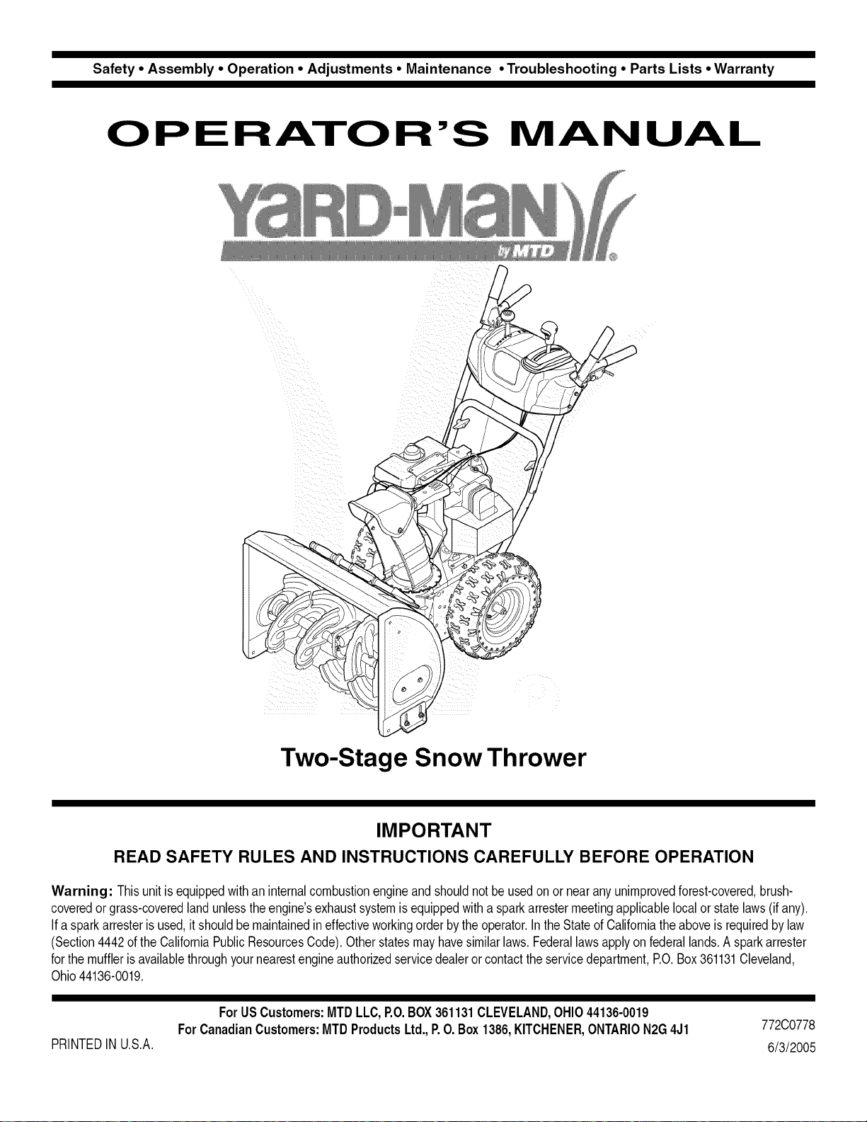
Two-Stage Snow Thrower
IMPORTANT
READ SAFETY RULES AND INSTRUCTIONS CAREFULLY BEFORE OPERATION
Warning: Thisunitisequippedwithan internalcombustionengineandshouldnotbeusedon or nearanyunimprovedforest-covered,brush-
coveredor grass-coveredlandunlesstheengine'sexhaustsystemisequippedwithasparkattestermeetingapplicablelocalor statelaws(if any),
If a sparkarresterisused,it shouldbemaintainedineffectiveworkingorderbytheoperator,IntheStateofCaliforniatheaboveisrequiredbylaw
(Section4442oftheCaliforniaPublicResourcesCode),Otherstatesmayhavesimilarlaws,Federallawsapplyonfederallands,A sparkattester
forthemufflerisavailablethroughyournearestengineauthorizedservicedealeror contacttheservicedepartment,P.O,Box361131Cleveland,
Ohio44136-0019,
PRINTEDIN U,S,A,
ForUSCustomers: MTDLLC,P.O.BOX361131CLEVELAND,OHIO44136-0019
ForCanadianCustomers:MTDProductsLtd.,P.O.Box1386,KITCHENER,ONTARION2G4J1
772C0778
6/3/2005
This Operator's Manual is an important part of your new snow thrower. It will help you assemble,
prepare and maintain the unit for best performance. Please read and understand what it says.
Table of Contents
Safety Labels ...................................................... 3
Safe Operation Practices ................................... 4
Setting Up Your Snow Thrower .......................... 6
Operating Your Snow Thrower ......................... 10
MakingAdjustments ......................................... 14
Maintaining Your Snow Thrower ...................... 16
Off-Season Storage .......................................... 20
Trouble Shooting .............................................. 21
Warranty ............................................................ 22
Illustrated Parts Lists ....................................... 23
Finding and Recording Model Number
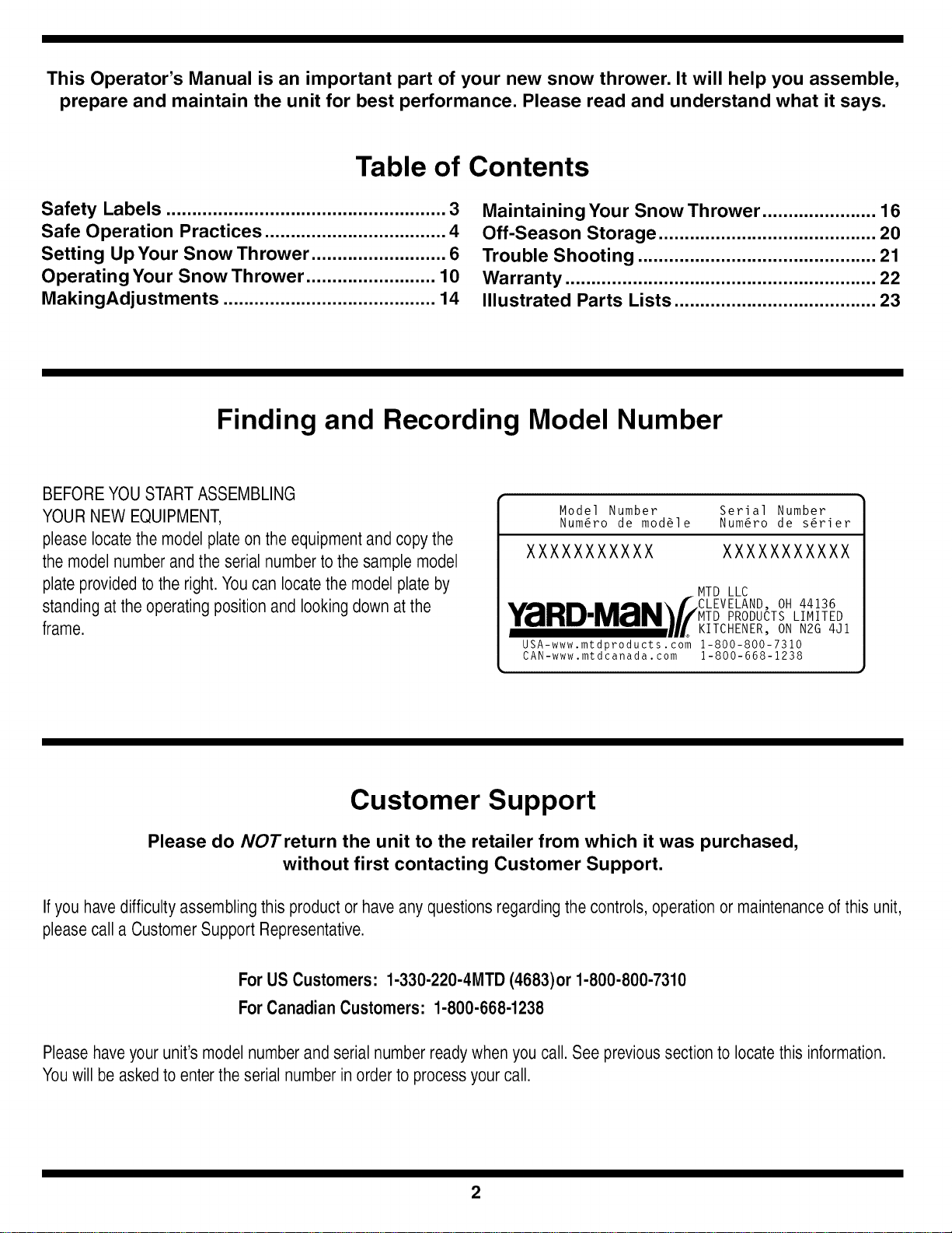
BEFOREYOU STARTASSEMBLING
YOURNEW EQUIPMENT,
please locatethe modelplate onthe equipmentand copythe
themodel number andthe serial number tothe sample model
plate providedto theright.You can locatethe modelplate by
standing atthe operatingposition and looking down atthe
frame.
Model Number Serial Number
Num6ro de mod61e Num6ro de s6rier
XXXXXXXXXXX XXXXXXXXXXX
MTD LLC
•,,A .... m,,,.\f CLEVELAND, OH 44136
Y_IIHUIMZrIN_//MTD PRODUCTS LIMITED
........... UL KITCHENER, ON N2G 4Jl
USA-www.mtdproducts.com 1-800-800-7310
CAN-www.mtdcanada. com 1-800-668-1238
Customer Support
Please do NOTreturn the unit to the retailer from which it was purchased,
without first contacting Customer Support.
Ifyou havedifficultyassemblingthis productor haveany questionsregardingthe controls, operationor maintenanceof this unit,
pleasecall a CustomerSupport Representative.
For US Customers: 1-330-220-4MTD (4683)or 1-800-800-7310
ForCanadian Customers: 1-800-668-1238
Pleasehaveyour unit'smodelnumber and serial number readywhen you call. See previoussection to locate this information.
Youwill beaskedto entertheserial number in orderto processyour call.
2
CS00071
STOP
ChuteClean-out
Tool
,J
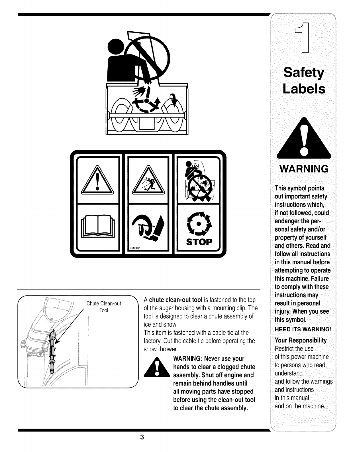
A chute clean-out tool isfastenedto thetop
of theauger housingwith a mountingclip.The
tool isdesignedto clear a chuteassemblyof
ice and snow.
Thisitemis fastenedwith a cabletie atthe
factory.Cut thecable tie beforeoperatingthe
snowthrower.
WARNING: Never useyour
handsto clear a cloggedchute
assembly.Shut off engineand
remainbehind handles until
all movingparts havestopped
beforeusing the clean-out tool
to clear the chuteassembly.
WARNING
Thissymbol points
out important safety
instructions which,
ifnotfollowed,could
endangerthe per-
sonalsafety and/or
propertyof yourself
and others.Readand
followall instructions
inthis manual before
attemptingto operate
this machine.Failure
to complywith these
instructionsmay
resultin personal
injury.Whenyou see
this symbol.
HEED ITS WARNING!
Your Responsibility
Restrictthe use
of this power machine
to persons who read,
understand
and follow thewarnings
and instructions
inthis manual
and onthe machine.
3
WARNING
i outimportantsafety
i instructionswhich,
i ifnotfollowed,could
i endangerthe per-
sonalsafetyand/or
propertyofyourself
andothers.Readand
followall instructions
inthis manual before
attemptingto operate
i this machine.Failure
! to complywith these
i instructionsmay
i resultinpersonal
i injury.Whenyou see
I this symbol.
i HEED ITS WARNING!
;;Your Responsibility
i Restricttheuse
i ofthis powermachine
to personswho read,
understand
andfollow the warnings
and instructions
inthis manual
andonthe machine.
WARNING: EngineExhaust,some of itsconstituents,andcertain vehiclecompo-
nentscontain or emit chemicals knownto Stateof Californiato cause cancerand
birth defectsor other reproductiveharm.
DANGER: This machinewas builtto beoperatedaccordingto the rulesfor safe operation in this
manual.As with anytype of powerequipment,carelessnessor erroronthe part ofthe operatorcan
result inseriousinjury.This machine iscapableof amputatinghands andfeet andthrowing objects.
Failureto observethe followingsafety instructionscould resultin serious injuryor death.
Training
1. Read,understand,andfollowall instructionsonthe 1.
machineandin themanual(s)beforeattemptingto
assembleandoperate.Keepthismanualinasafe placefor
futureandregularreferenceandfor orderingreplacement
parts. 2.
2. Befamiliarwithall controlsandtheirproperoperation.
Knowhowto stopthe machineanddisengagethemquickly.
3. Neverallowchildrenunder14yearsoldto operatethis
machine.Children14yearsoldandovershouldreadand
understandtheoperationinstructionsand safetyrulesin 3.
thismanualandshouldbetrainedandsupervisedbya
parent.
4. Neverallowadultsto operatethis machinewithoutproper
instruction.
5. Thrownobjectscancauseseriouspersonalinjury.Plan 4.
yoursnow-throwingpatternto avoiddischargeof material
towardroads,bystandersandthe like.
6. Keepbystanders,helpers,petsandchildrenatleast75feet 5.
fromthe machinewhileit isin operation.Stopmachineif
anyoneentersthe area. 6.
7. Exercisecautiontoavoidslippingorfalling,especially 7.
whenoperatinginreverse.
8,
9.
Preparation
Thoroughlyinspectthe areawherethe equipmentisto be
used.Removealldoormats,newspapers,sleds,boards,
wiresandotherforeignobjects,whichcouldbetrippedover
orthrownbythe auger/impeller.
Alwayswearsafetyglassesor eyeshieldsduringoperation
andwhile performinganadjustmentorrepairto protectyour
eyes.Thrownobjectswhich ricochetcancauseserious
injurytothe eyes.
Do notoperatewithoutwearingadequatewinterouter
garments.Do notwearjewelry,longscarvesorother
looseclothing,whichcould becomeentangledin moving
parts.Wearfootwearwhich willimprovefootingonslippery
surfaces.
Useagroundedthree-wireextensioncordand receptacle
forall unitswithelectric startengines.
Adjustcollectorhousingheighttocleargravelorcrushed
rocksurfaces.
Disengageallcontrolleversbeforestartingthe engine.
Neverattemptto makeanyadjustmentswhileengineis
running,exceptwherespecificallyrecommendedinthe
operator'smanual.
Letengineandmachineadjusttooutdoortemperature
beforestartingtoclearsnow.
Toavoidpersonalinjuryor propertydamageuseextreme
careinhandlinggasoline.Gasolineisextremelyflammable
andthe vaporsareexplosive.Seriouspersonalinjurycan
occurwhengasolineis spilledonyourselforyourclothes,
whichcanignite.Washyourskinand changeclothes
immediately.
a. Useonlyanapprovedgasolinecontainer.
b. Extinguishallcigarettes,cigars,pipesandothersources
ofignition.
c. Neverfuel machineindoors.
d. Neverremovegascap oradd fuelwhilethe engineis hot
or running.
e. Allowengineto coolat leasttwo minutesbeforerefuel-
ing.
f. Neveroverfillfueltank.Filltankto nomorethanY2inch
belowbottomoffiller neckto providespacefor fuel
expansion.
g. Replacegasolinecap andtightensecurely.
h. If gasolineis spilled,wipe itoff theengineand equip-
ment.Movemachinetoanotherarea.Wait5 minutes
beforestartingtheengine.
i. Neverstorethe machineorfuel containerinsidewhere
there isan openflame,sparkor pilotlight(e.g.furnace,
waterheater,spaceheater,clothesdryeretc.).
j. Allowmachinetocoolat least5 minutesbeforestoring.
4
Operation
1. Donot puthandsorfeet nearrotatingparts,inthe
auger/impellerhousingor chuteassembly.Contactwiththe
rotatingpartscanamputatehandsandfeet.
2. The auger/impellercontrolleveris asafetydevice.Never
bypassitsoperation.Doingsomakesthe machineunsafe
andmaycausepersonalinjury.
3. The controlleversmustoperateeasilyin bothdirections
andautomaticallyreturntothe disengagedpositionwhen
released.
4. Neveroperatewitha missingor damagedchuteassembly.
Keepall safetydevicesin placeandworking.
5. Neverrunan engineindoorsor inapoorlyventilatedarea.
Engineexhaustcontainscarbonmonoxide,anodorlessand
deadlygas.
6. Donotoperatemachinewhileunderthe influenceofalcohol
or drugs.
7. Mufflerandenginebecomehotandcan causea burn.Do
nottouch.
8. Exerciseextremecautionwhenoperatingonor crossing
gravelsurfaces.Stayalertfor hiddenhazardsortraffic.
9. Exercisecautionwhenchangingdirectionandwhileoperat-
ingonslopes.
10.Planyoursnow-throwingpatternto avoiddischargetowards
windows,walls,carsetc.Thus,avoidingpossibleproperty
damageor personalinjury causedbyaricochet.
11.Neverdirectdischargeatchildren,bystandersand petsor
allow anyonein frontofthe machine.
12.Donotoverloadmachinecapacity byattemptingto clear
snowattoofast ofa rate.
13.Neveroperatethis machinewithoutgoodvisibilityor light.
Alwaysbesureofyourfootingand keepafirmholdonthe
handles.Walk,neverrun.
14.Disengagepowerto the auger/impellerwhentransportingor
notin use.
15.Neveroperatemachineat hightransportspeedsonslippery
surfaces.Lookdownandbehindand usecarewhen
backingup.
16.Ifthe machineshouldstartto vibrateabnormally,stopthe
engine,disconnectthesparkplugwireand groundit against
the engine.Inspectthoroughlyfordamage.Repairany
damagebeforestartingandoperating.
17.Disengageallcontrolleversandstopenginebeforeyou
leavethe operatingposition(behindthe handles).Wait
untilthe auger/impellercomestoa completestop before
uncloggingthe chuteassembly,makinganyadjustments,or
inspections.
18.Neverputyourhandin thedischargeor collectoropenings.
Alwaysusethe clean-outtoolprovidedtounclogthe dis-
chargeopening.Donot unclogchuteassemblywhileengine
isrunning.Shutoffengineand remainbehindhandlesuntil
all movingpartshavestoppedbeforeunclogging.
19.Useonlyattachmentsandaccessoriesapprovedbythe
manufacturer(e.g.wheelweights,tire chains,cabsetc.).
20. Ifsituationsoccurwhicharenotcoveredin thismanual,use
careand goodjudgment.Callcustomerassistanceforthe
nameof yournearestservicingdealer.
Maintenance & Storage
1. Nevertamperwithsafetydevices.Checktheirproper
operationregularly.
2. Disengageall controlleversandstoptheengine.Waituntil
theauger/impellercometo acompletestop.Disconnectthe
sparkplugwireandgroundagainstthe engineto prevent
unintendedstartingbeforecleaning,repairing,orinspecting.
3. Checkboltsandscrewsforpropertightnessatfrequent
intervalstokeepthe machineinsafeworkingcondition.
Also,visuallyinspectmachineforanydamage.
4. Do notchangethe enginegovernorsettingor over-speed
theengine.Thegovernorcontrolsthemaximumsafe
operatingspeedoftheengine.
5. Snowthrowershaveplatesandskidshoesaresubjectto
wearanddamage.Foryoursafetyprotection,frequently
checkallcomponentsand replacewith originalequipment
manufacturer's(OEM)partsonly."Useof partswhichdo
notmeetthe originalequipmentspecificationsmayleadto
improperperformanceandcompromisesafety!"
6. Checkcontrolsperiodicallytoverify theyengageand
disengageproperlyandadjust,if necessary.Referto the
adjustmentsectioninthis operator'smanualfor instructions.
7. Maintainor replacesafetyandinstructionlabels,as neces-
sary.
8. Observeproperdisposallawsandregulationsforgas,oil,
etc.toprotectthe environment.
9. Priorto storing,runmachineafewminutestoclearsnow
frommachineandpreventfreezeupof auger/impeller.
10.Neverstorethe machineorfuel containerinsidewhere
thereisan openflame,sparkor pilotlightsuchasa water
heater,furnace,clothesdryeretc.
11.Alwaysreferto theoperator'smanualforproperinstructions
onoff-seasonstorage.
Do not modify engine
Toavoidseriousinjuryordeath,donot modifyengineinany
way.Tamperingwiththegovernorsettingcan leadto arunaway
engineandcauseit tooperateatunsafespeeds.Nevertamper
withfactorysettingofenginegovernor.
Notice regarding Emissions
Engineswhicharecertifiedto complywithCaliforniaandfederal
EPAemissionregulationsforSORE(SmallOff RoadEquipment)
arecertifiedtooperateonregularunleadedgasoline,andmay
includethefollowingemissioncontrolsystems:EngineModifica-
tion(EM)andThreeWayCatalyst(TWC)ifso equipped.
ces
WARNING
endangerthe per-
sonalsafety and/or
property of yourself
and others. Readand
followall instructions
in this manual before
attemptingto operate
this machine. Failure
to complywith these
instructionsmay
result in personal
injury.Whenyou see
Ihis symbol.
HEED IT'S WARNING!
_our Responsibility
Restrictthe use
ofthis powermachine
to personswho read,
understand
andfollow the warnings
and instructions
in this manua
and onthe machine.
5
NOTE:Referencesto
rightorleftsideofthe
snowthroweraredeter-
minedfrombehindthe
unitintheoperating
position.
NOTE:ThisOperator's
Manualcoversseveral
models,handlepanels,
i lightsandchutecranks
aresomefeaturesthat
mayvarybymodel.
Notallfeaturesrefer-
encedinthismanual
areapplicabletoall
snowthrowermodels.
I NOTE:Tworeplace-
mentaugershearpins
i areincludedwiththis
manual(orstowed
intheplastichandle
i panel).RefertoAugers
intheMaintainance
i Sectionformore
i informationregarding
shearpinreplacement.
Figure 1
Figure 2
Figure 3
IMPORTANT:Thesnowthrowerisshippedwithoil
andWITHOUTGASOLINE.Afterassembly,referto
separateenginemanualforproperfuelandengineoil
recommendations.
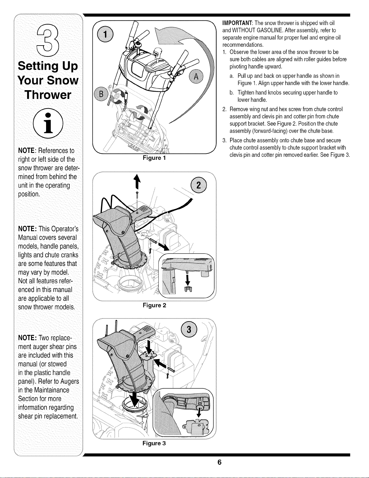
1. Observethelowerareaofthesnowthrowertobe
surebothcablesarealignedwithrollerguidesbefore
pivotinghandleupward,
a. Pullupand backon upperhandleasshownin
Figure1.Alignupperhandlewiththelowerhandle,
b. Tightenhandknobssecuringupperhandleto
lowerhandle,
2. Removewingnutand hexscrewfromchutecontrol
assemblyandclevispinandcotterpinfromchute
supportbracket.SeeFigure2. Positionthechute
assembly(forward-facing)overthechutebase.
3. Placechuteassemblyontochutebaseand secure
chutecontrolassemblytochutesupportbracketwith
clevispinandcotterpin removedearlier.SeeFigure3.
6
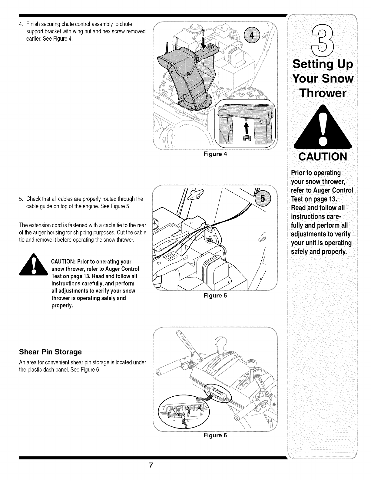
4, Finishsecuringchutecontrolassemblytochute
supportbracketwithwingnutandhexscrewremoved
earlier,SeeFigure4,
5, Checkthatall cablesareproperlyroutedthroughthe
cableguideon topoftheengine,SeeFigure5,
Theextensioncordisfastenedwitha cabletietothe rear
oftheaugerhousingforshippingpurposes,Cutthecable
tieand removeit beforeoperatingthesnowthrower,
CAUTION:Priortooperatingyour
snowthrower,refertoAugerControl
Teston page13.Readandfollow all
instructionscarefully,andperform
alladjustmentstoverifyyoursnow
throwerisoperatingsafelyand
properly.
Shear Pin Storage
An areaforconvenientshearpin storageis locatedunder
theplasticdashpanel,SeeFigure6,
Figure 4
Figure 5
Figure 6
Priorto operating
your snowthrower,
referto Auger Control
Teston page 13.
Read and follow all
instructionscare-
fully and perform all
adjustmentstoverify
your unit isoperating
safelyand properly.
7
i
WARNING
Neveruse your hands
to clean snow and
icefromthe chute
assemblyor auger
housing.
IMPORTANT
Underany circum-
stance do notexceed
manufacturer'srecom-
mended psi. Equaltire
pressureshouldbe
maintainedat alltimes.
Excessivepressure
i whenseatingbeads
maycause tire/rim
assemblyto burst
with forcesufficientto
cause seriousinjury.
i Referto sidewallof
i tirefor recommended
i pressure.
Figure 7
Figure 8
Figure 9
8
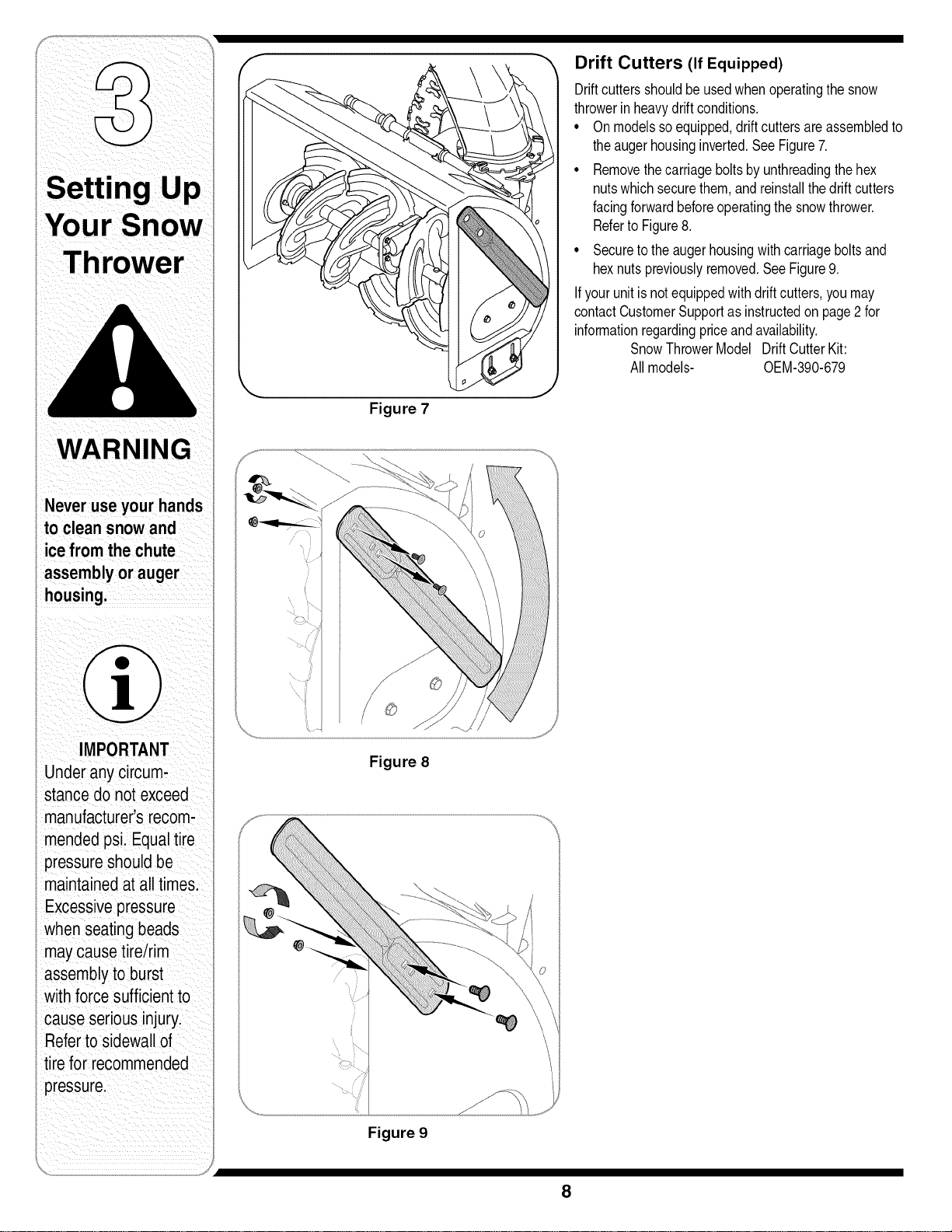
Drift Cutters (If Equipped)
Driftcuttersshouldbeusedwhenoperatingthesnow
throwerinheavydriftconditions,
• Onmodelssoequipped,driftcuttersare assembledto
theaugerhousinginverted,SeeFigure7,
• Removethecarriageboltsbyunthreadingthehex
nutswhichsecurethem,and reinstallthedriftcutters
facingforwardbeforeoperatingthesnowthrower.
Referto Figure8,
• Securetotheaugerhousingwithcarriageboltsand
hexnutspreviouslyremoved,SeeFigure9,
If yourunitisnotequippedwithdriftcutters,youmay
contactCustomerSupportas instructedonpage2for
informationregardingpriceand availability,
SnowThrowerModel DriftCutterKit:
Allmodels- OEM-390-679
Clean-Out
Tool
Figure 10
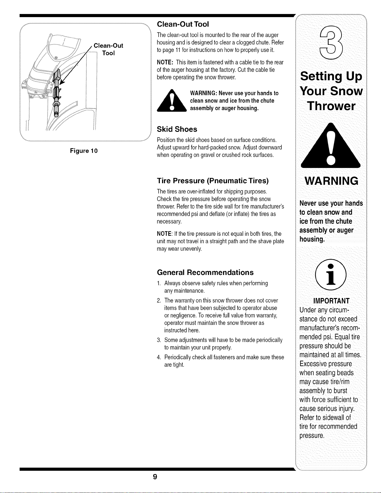
Clean-Out Tool
Theclean-outtoolismountedtotherearoftheauger
housingandisdesignedtocleara cloggedchute.Refer
topage11forinstructionson howtoproperlyuseit.
NOTE: This itemisfastenedwith acabletie totherear
oftheaugerhousingatthefactory.Cutthecabletie
beforeoperatingthesnowthrower.
,_ WARNING:Neveruseyourhandsto
cleansnowandice fromthechute
assemblyor augerhousing.
Skid Shoes
Positiontheskid shoesbasedon surfaceconditions.
Adjustupwardforhard-packedsnow.Adjustdownward
whenoperatingongravelorcrushedrocksurfaces.
Tire Pressure (Pneumatic Tires)
Thetiresareover-inflatedforshippingpurposes.
Checkthetirepressurebeforeoperatingthesnow
thrower.Refertothetiresidewallfortiremanufacturer's
recommendedpsianddeflate(or inflate)thetiresas
necessary.
NOTE:If thetirepressureisnotequalin bothtires,the
unitmaynottravelin a straightpathandtheshaveplate
maywearunevenly.
General Recommendations
,
2,
Alwaysobservesafetyruleswhenperforming
anymaintenance.
Thewarrantyon thissnowthrowerdoesnotcover
itemsthathavebeensubjectedtooperatorabuse
or negligence.Toreceivefullvaluefromwarranty,
operatormustmaintainthe snowthroweras
instructedhere.
3. Someadjustmentswillhaveto bemadeperiodically
tomaintainyourunitproperly.
4. Periodicallycheckall fastenersand makesurethese
aretight.
9
g
Your Snow
WA RNING
Under anycircum,
stance do notexceed
manufactureCs recom:
mendedpsi.Equal tire
pressureshould be
maintained at alltimes,
when seatingbeads
maycausetire/rim
assemblytoburst
with forcesufficienttO
cause seriousinjury.
Referto sidewallOf
tire for recommended
i I ii_ii ii i _ i i
WARNING
Read, understand,
andfollow all instruc-
Lionsand warnings
onthe machineand
in this manual before
operating.
Useextreme care
when handling
gasoline.Gasoline is
extremelyflammable
andthe vapors are
explosive.Neverfuel
the machineindoors
or while the engine
is hotor running.
Extinguishcigarettes,
cigars,pipes and
other sourcesof
ignition.
f
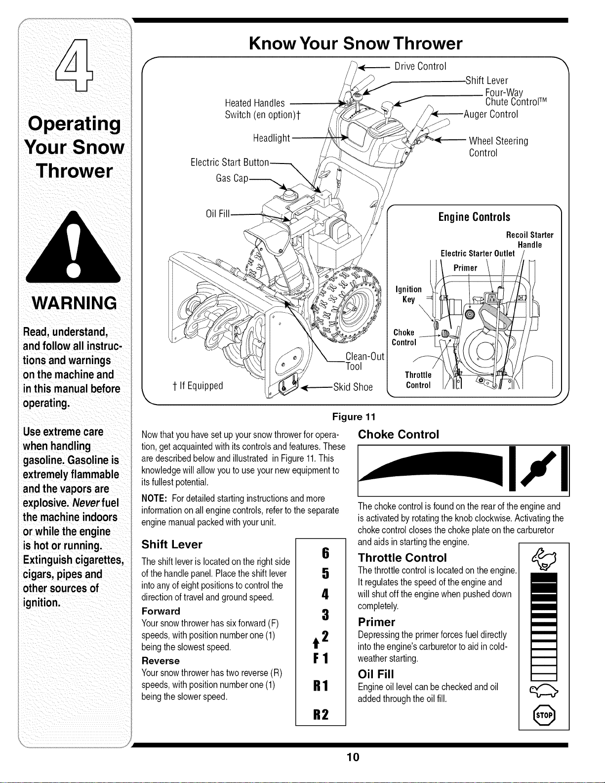
Know Your Snow Thrower
HeatedHandles
Switch(en option)l-
Drive Control
.ShiftLever
Four-Way
ChuteControFM
JgerControl
Headlig
ElectricStart
WheelSteering
Control
GasCa
Oil
1 If Equipped
Clean-Out
tool
Ignition
Key
Choke
Control
Throttle
Control
EngineControls
RecoilStarter
Handle
ElectricStarter Outlet
Primer
J
Figure 11
Nowthatyouhavesetup yoursnowthrowerforopera-
tion,getacquaintedwithits controlsandfeatures.These
aredescribedbelowandillustratedin Figure11.This
knowledgewillallowyoutouseyournewequipmentto
itsfullestpotential.
NOTE: Fordetailedstartinginstructionsandmore
informationonall enginecontrols,refertotheseparate
enginemanualpackedwithyourunit.
Shift Lever
Theshiftleverislocatedontherightside
ofthehandlepanel.Placetheshiftlever
intoanyofeightpositionstocontrolthe
directionof travelandgroundspeed.
Forward
Yoursnowthrowerhassixforward(F)
speeds,withpositionnumberone (1)
beingtheslowestspeed.
Reverse
Yoursnowthrowerhastwo reverse(R)
speeds,withpositionnumberone (1)
beingtheslowerspeed.
6
5
4
3
t 2
F1
R1
R2
Choke Control
I111
Thechokecontrolisfoundontherearoftheengineand
isactivatedbyrotatingtheknobclockwise.Activatingthe
chokecontrolclosesthechokeplateon thecarburetor
andaidsinstartingtheengine.
Throttle Control
Thethrottlecontrolis locatedon theengine.
It regulatesthespeedoftheengineand
willshutoff theenginewhenpusheddown
completely.
Primer
Depressingtheprimerforcesfueldirectly
intotheengine'scarburetortoaidin cold-
weatherstarting.
Oil Fill
Engineoil levelcanbecheckedandoil
addedthroughtheoil fill.
q;::b,
@
10
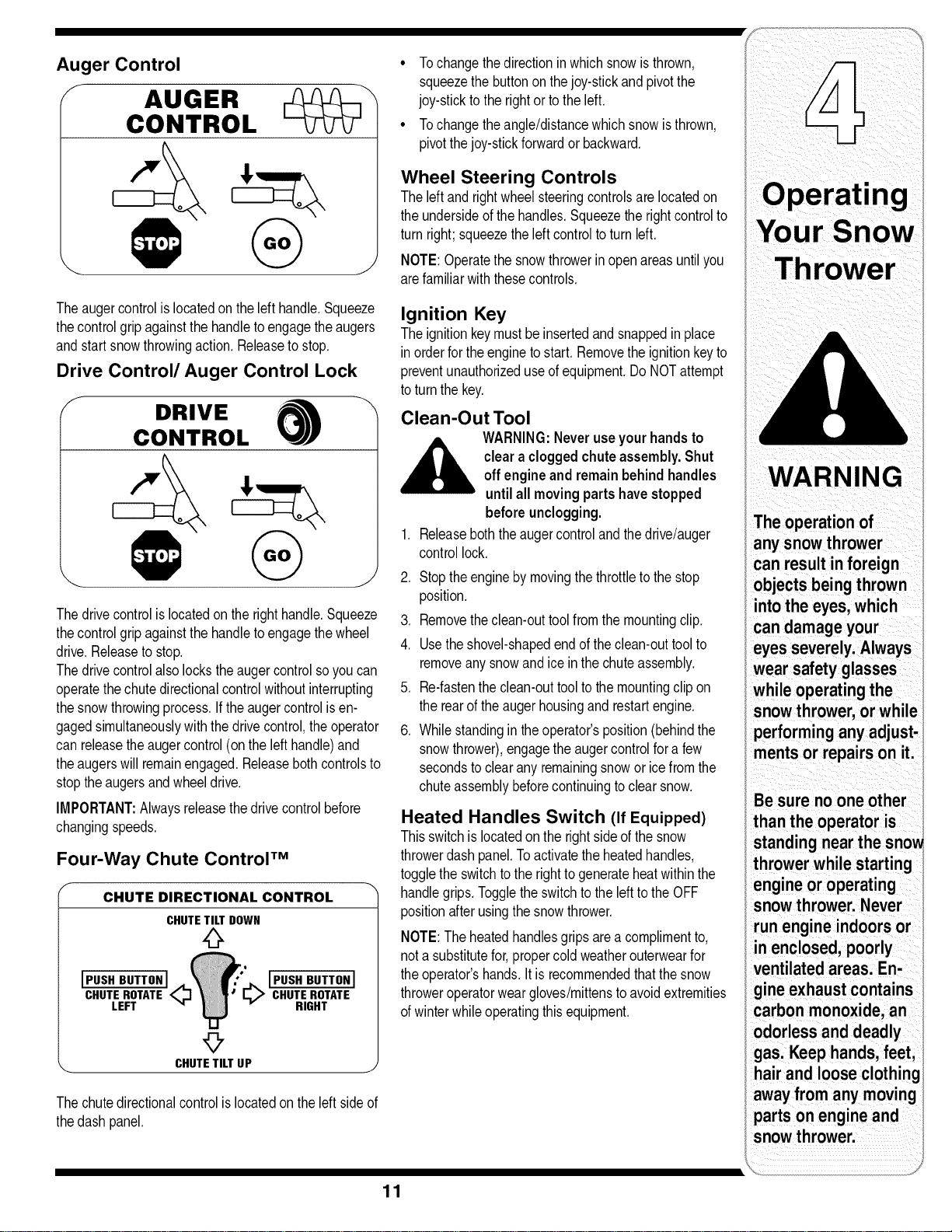
Auger Control
f
AUGER
CONTROL
J
Theaugercontrolislocatedontheleft handle.Squeeze
thecontrolgripagainstthehandletoengagetheaugers
andstartsnowthrowingaction.Releasetostop.
Drive Control/Auger Control Lock
f DRIVE _
CONTROL
Thedrivecontrolislocatedontherighthandle.Squeeze
thecontrolgripagainstthehandletoengagethewheel
drive.Releasetostop.
Thedrivecontrolalsolockstheaugercontrolsoyoucan
operatethechutedirectionalcontrolwithoutinterrupting
thesnowthrowingprocess.If theaugercontrolisen-
gagedsimultaneouslywiththedrivecontrol,theoperator
canreleasetheaugercontrol(onthe lefthandle)and
theaugerswillremainengaged.Releasebothcontrolsto
stoptheaugersandwheeldrive.
IMPORTANT:Alwaysreleasethedrivecontrolbefore
changingspeeds.
Four-Way Chute Control TM
f
CHUTE DIRECTIONAL CONTROL
CHUTETILTDOWN
0
JPUSHBUTTONJ
CHUTEROTATE_.
LEFT "q
JPUSH BUTTONJ
CHUTEROTATE
RIGHT
9
_. CHUTETILTUP j
Thechutedirectionalcontrolislocatedon theleftsideof
thedashpanel.
• Tochangethedirectioninwhichsnowisthrown,
squeezethe buttononthejoy-stickandpivotthe
joy-stickto therightortotheleft.
• Tochangetheangle/distancewhichsnowisthrown,
pivotthejoy-stickforwardor backward.
Wheel Steering Controls
Theleftand rightwheelsteeringcontrolsare locatedon
theundersideofthehandles.Squeezetherightcontrolto
turnright;squeezetheleftcontroltoturnleft.
NOTE:Operatethesnowthrowerin openareasuntilyou
arefamiliarwiththesecontrols.
Ignition Key
Theignitionkeymustbe insertedandsnappedin place
inorderfortheenginetostart. Removetheignitionkeyto
preventunauthorizeduseofequipment.DoNOTattempt
toturnthekey.
Clean-Out Tool
WARNING:Neveruseyourhandsto
clearacloggedchuteassembly.Shut
offengineandremainbehindhandles
untilall movingpartshavestopped
beforeunclogging.
Releaseboththeaugercontroland thedrive/auger
controllock.
,
2. Stoptheenginebymovingthethrottletothestop
position.
3. Removetheclean-outtoolfromthemountingclip.
4. Usetheshovel-shapedendoftheclean-outtoolto
removeanysnowandiceinthechuteassembly.
5. Re-fastentheclean-outtoolto themountingclipon
therearoftheaugerhousingandrestartengine.
6. Whilestandingin theoperator'sposition(behindthe
snowthrower),engagetheaugercontrolfora few
secondsto clearanyremainingsnowor icefromthe
chuteassemblybeforecontinuingtoclearsnow.
Heated Handles Switch (If Equipped)
Thisswitchis locatedon therightsideofthesnow
throwerdashpanel.Toactivatetheheatedhandles,
toggletheswitchtotherightto generateheatwithinthe
handlegrips.ToggletheswitchtothelefttotheOFF
positionafterusingthesnowthrower.
NOTE:Theheatedhandlesgripsarea complimentto,
nota substitutefor,propercoldweatherouterwearfor
theoperator'shands.Itis recommendedthatthesnow
throweroperatorweargloves/mittenstoavoidextremities
ofwinterwhileoperatingthis equipment.
WARNING
The operation of
any snowthrower
can result in foreign
objects beingthrown
intothe eyes, which
candamage your
eyesseverely.Always
wear safety glasses
while operatingthe
snowthrower,or while
performing anyadjust-
ments or repairson it.
throwerwhile starting
engineor operating
snowthrower. Never
run engineindoors or
in enclosed,poorly
ventilatedareas. En-
gine exhaustcontains
carbon monoxide,an
odorless and deadly
gas. Keep hands,feet,
hairand loose clothing
awayfrom any moving
parts onengine and
snowthrower.
11
!iii i iii i ii!i/ iiii
WARNING
Read, understand,
and followall instruc-
tions and warnings
onthe machineand
in this manual before
operating.
Useextreme care
when handling
gasoline.Gasoline is
extremelyflammable
and the vapors are
explosive.Neverfuel
the machineindoors
or while the engine
is hot or running.
Extinguishciga-
rettes, cigars, pipes
and other sources of
ignition.
Ifyour home'swiring
system is not a
three-wire grounded
system,do not use
this electric starter
under anycondi-
tions.
Ifyour home
electricalsystem
is grounded,
but a three-hole
receptacle is not
available,do not use
your snow thrower's
electricstarter.
Gas & Oil Fill-Up
Servicetheenginewithgasolineandoil asinstructedin
theseparateenginemanualpackedwithyourunit,Read
instructionscarefully.
Starting The Engine
1, Attachsparkplugwireto sparkplug.Makecertainthe
metalloopon theendofthesparkplugwire(inside
therubberboot)isfastenedsecurelyoverthe metal
tiponthesparkplug.
2, Makecertainboththeaugercontrolanddrivecontrol
arein thedisengaged(released)position,
3, Movethrottlecontrolupto FASTposition.Insert
ignitionkeyintoslot.Makesureitsnapsintoplace.
Donotattempttoturnthekey,
NOTE:Theenginecannotstartunlessthekeyis
insertedintoignitionswitch,
Electric Starter
1, Determinethatyourhome'swiringisa three-wire
groundedsystem,Ask a licensedelectricianifyouare
notcertain.
WARNING:Theoptionalelectricstarter
,__is equippedwitha groundedthree-wire
powercordandplug,andisdesigned
tooperateon 120voltAC household
current.It mustbeusedwitha properly
groundedthree-prongreceptacleatall
timestoavoidthe possibilityofelectric
shock.Followall instructionscarefully
priortooperatingtheelectricstarter.
If youhavea groundedthree-prongreceptacle,proceed
asfollows:
1, Plugtheextensioncordintotheoutletlocatedonthe
engine'ssurface,Plugtheotherendofextensioncord
intoa three-prong120-volt,grounded,ACoutletina
well-ventilatedarea.
2, RotatechokecontroltoFULLchokeposition(fora
coldenginestart),
NOTE:Iftheengineisalreadywarm,placechokecontrol
inthe OFFpositioninsteadofFULL.
3, Pushtheprimertwoor threetimesforcoldengine
start,makingsuretocoverventholein thecenterof
theprimerwhenpushing,
NOTE:DONOTuseprimertorestartawarmengine
aftera shortshutdown.
4, Pushstarterbuttontostartengine.
5, Oncetheenginestarts,immediatelyreleasestarter
button.
6, Astheenginewarms,slowlyrotatethechokecontrol
totheOFFposition.Iftheenginefalters,quickly
rotatethechokecontrolbackto FULLand thenslowly
intotheOFFpositionagain.
7, Whendisconnectingtheextensioncord,always
unplugtheendat thethree-prongwalloutletbefore
unpluggingtheoppositeendfromthesnowthrower.
Recoil Starter
1, Rotatechokecontrolto FULLchokeposition(cold
enginestart),
NOTE:If theengineisalreadywarm,placechokecontrol
intheOFFpositioninsteadof FULL.
2, Pushthe primertwoor threetimesforcoldengine
start,makingsuretocoverventholeinthecenterof
theprimerwhenpushing,
NOTE:DONOTuseprimerto restarta warmengine
aftera shortshutdown.
NOTE:Additionalprimingmaybe necessaryifthe
temperatureis below15oFahrenheit,
3, Graspthe recoilstarterhandleand slowlypullthe
ropeout,Atthepointwhereit becomesslightlyharder
topulltherope,slowlyallowthe ropeto recoil.
4, Pullthe starterhandlewitha firm,rapidstroke,Donot
releasethehandleandallowitto snapback,Keepa
firmholdon thestarterhandleandallowitto slowly
recoil,
,
Astheenginewarms,slowlyrotatethechokecontrol
totheOFFposition.Iftheenginefalters,quicklyrotate
thechokecontrolbacktothe FULLpositionandthen
slowlyintotheOFFpositionagain.
NOTE:Allowtheenginetowarmup fora few minutes
afterstarting.Theenginewillnotdevelopfull poweruntil
itreachesoperatingtemperatures.
Stopping The Engine
Runenginefora fewminutesbeforestoppingtohelpdry
offanymoistureontheengine.
• Tohelppreventpossiblestarterfreeze-up,proceedas
follows:
Electric Starter (If Equipped)
1, Connectextensioncordtotheelectricstarteroutlet
ontheengine,thento120voltACoutlet.
2, Withtheenginerunning,pushthestarterbuttonand
allowthe starterforspinforseveralseconds,The
noisemadebythestarterisnormal,Theengine's
starteris notbeingharmed.
3, Whendisconnectingtheextensioncord,always
unplugtheendat thethree-prongwalloutletbefore
unpluggingtheoppositeendfromthesnowthrower.
4, MovethrottlecontroltoSTOPposition.
5, Removetheignitionkey(Donotturnkey)to prevent
unauthorizeduseofequipment,
6, Wipeallsnowandmoisturefromtheareaaroundthe
engineaswellastheareainandaroundthedrive
controlandaugercontrol,Also,engageandrelease
bothcontrolsseveraltimes.
12
NOTE:Keepthekeyin a safeplace.Theenginecannot
startwithouttheignitionkey.
Recoil Starter
1. Withenginerunning,pullstarterropewitha rapid,
continuousfullarmstrokethreeor fourtimes.Pulling
thestarterropewillproducea loudclatteringsound,
whichisnotharmfultoengine.
2. MovethrottlecontroltoSTOPposition.
3. Removethe ignitionkey(Donotturnkey)toprevent
unauthorizeduseofequipment.
NOTE:Keepthekeyin a safeplace.Theenginecannot
startwithouttheignitionkey.
4. Wipeall snowandmoisturefromtheareaaroundthe
engineaswellastheareain andaroundthedrive
controlandaugercontrol.Also,engageand release
bothcontrolsseveraltimes.
To Engage Drive
Withtheenginerunningneartopspeed,move
shiftleverto oneof sixFORWARDpositionsor two
REVERSEpositions.Selecta speedappropriatefor
thesnowconditionsthatexist.
2. Squeezedrivecontrolagainsttherighthandleand
thesnowthrowerwillmove.Releaseitandthedrive
motionwillstop.
3. Toturnthe unitleftor right,squeezetherespective
wheelsteeringcontrol.SeeFigure11.
To Engage Augers
1. Toengageaugersand startsnowthrowing,squeeze
thelefthandaugercontrolagainsttheleft handle.
Releaseto stopaugers.
2. Whiletheaugercontrolisengaged,squeezethedrive
controltomove,releasetostop.Donotshiftspeeds
whilethedriveisengaged.
NOTE:Thissameleveralsolocksaugercontrolsoyou
canturnthechutecontrolwithoutinterruptingthesnow
throwingprocess.
3. Releasetheaugercontrol;the interlockmechanism
shouldkeeptheaugercontrolengageduntilthedrive
controlis released.
,
Releasethedrivecontrolto stopboththeaugersand
thewheeldrive.Tostoptheauger,bothleversmust
be released.
Auger Control Test
Performthefollowingtestbeforeoperatingyoursnow
throwerforthefirsttimeandatthestartofeachwinter.
Checktheadjustmentoftheaugercontrolasfollows:
1. Whentheaugercontrolis releasedandin the
disengaged"up"position,thecableshouldhavevery
littleslack.It shouldNOTbetight.
2. Ina well-ventilatedarea,startthesnowthrower
engineasinstructedonthepreviouspage.Makesure
thethrottleissetin theFASTposition.
3. Whilestandingin theoperator'sposition(behindthe
snowthrower),engagetheauger.
4. Allowtheaugerto remainengagedforapproximately
ten(10)secondsbeforereleasingtheaugercontrol.
Repeatthisseveraltimes.
5. Withthethrottlecontrolin theFAST(rabbit)position
andtheaugercontrolinthedisengaged"up"position,
walktothefrontofthemachine.
6. Confirmthattheaugerhascompletelystopped
rotatingandshowsNOsignsofmotion.Iftheauger
showsANYsignsofrotating,immediatelyreturnto
theoperator'spositionandshutofftheengine.Wait
forALLmovingpartstostopbeforere-adjustingthe
augercontrol.
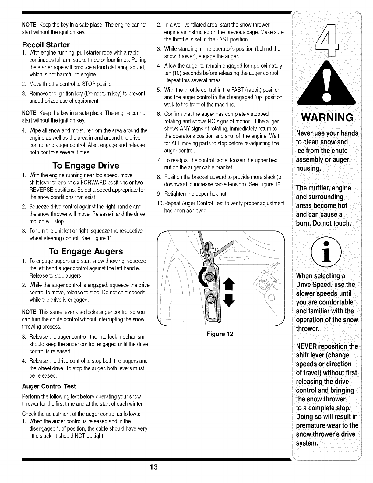
7. Toreadjustthecontrolcable,loosentheupperhex
nutontheaugercablebracket.
8. Positionthebracketupwardtoprovidemoreslack(or
downwardtoincreasecabletension).See Figure12.
9. Retightentheupperhexnut.
10.RepeatAugerControlTesttoverifyproperadjustment
hasbeenachieved.
Figure 12
WARN
Never useyour hands
to clean snow and
ice fromthe chute
The mufflerlengine
and surrounding
areas become hot
burn. Do nottouch.
When selectinga
Drive Speed. use the
slowerspeeds until
you are comfortable
and familiar with the
operation of thesnow
i
NEVERrepositionthe
shift lever(change
speeds or direction
control andbringing
the snowthrower
to a complete stop,
Doing so will resultin
prematurewear to the
snowthrower's drive
i
13
WARNING
Read,understand,
and follow all instruc-
tions and warnings
i on the machineand
inthis manual before
, operating.
Neverattempt to
makeanyadjust-
i mentswhile the
_engine is running,
i exceptwhere speci-
i fied in operator's
_manual.
///
Figure 13
Figure 14
Figure 15
if
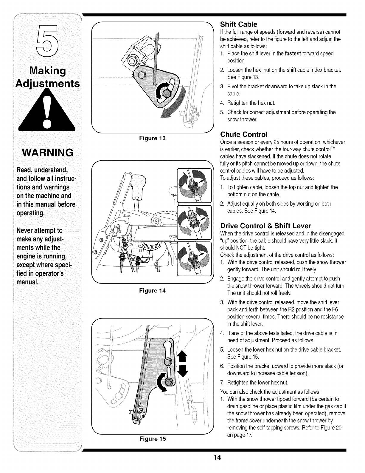
Shift Cable
If thefullrangeofspeeds(forwardandreverse)cannot
beachieved,refertothefiguretotheleftandadjustthe
shiftcableasfollows:
1, Placetheshiftleverin thefastest forwardspeed
position,
2, Loosenthehex nutontheshiftcableindexbracket,
SeeFigure13.
3. Pivotthebracketdownwardtotakeupslackinthe
cable,
4, Retightenthehexnut,
5. Checkforcorrectadjustmentbeforeoperatingthe
snowthrower.
Chute Control
Oncea seasonorevery25hoursofoperation,whichever
isearlier,checkwhetherthefour-waychutecontrolTM
cableshaveslackened,Ifthechutedoesnotrotate
fullyor itspitchcannotbe movedup ordown,thechute
controlcableswillhavetobeadjusted,
Toadjustthesecables,proceedasfollows:
1. Totightencable,loosenthetopnutandtightenthe
bottomnuton thecable.
2. Adjustequallyon bothsidesbyworkingonboth
cables,SeeFigure14,
Drive Control & Shift Lever
Whenthedrivecontrolisreleasedandin thedisengaged
"up"position,thecableshouldhaveverylittleslack.It
shouldNOTbetight.
Checktheadjustmentofthedrivecontrolasfollows:
1, Withthedrivecontrolreleased,pushthesnowthrower
gentlyforward,Theunitshouldrollfreely.
2, Engagethedrivecontrolandgentlyattempttopush
thesnowthrowerforward.Thewheelsshouldnotturn.
Theunitshouldnotrollfreely.
3, Withthedrivecontrolreleased,movetheshiftlever
backandforthbetweentheR2positionandtheF6
positionseveraltimes,Thereshouldbeno resistance
in theshiftlever,
4, If anyoftheabovetestsfailed,thedrivecableisin
needofadjustment,Proceedasfollows:
5, Loosenthelowerhexnutonthedrivecablebracket,
SeeFigure15,
6, Positionthebracketupwardtoprovidemoreslack(or
downwardto increasecabletension),
7. Retightenthelowerhexnut,
Youcanalsochecktheadjustmentasfollows:
1, Withthesnowthrowertippedforward(becertainto
draingasolineorplaceplasticfilm underthegascapif
thesnowthrowerhasalreadybeenoperated),remove
theframecoverunderneaththesnowthrowerby
removingtheself-tappingscrews,Referto Figure20
onpage 17.
14
2. Withthedrivecontrolreleased,theremustbe 1/8"
clearancebetweenthefrictionwheelandthedrive
pulleyin all positionsof theshiftlever.
3. Withthedrivecontrolengaged,thefrictionwheelmust
contactthedrivepulley.Referto Figure28on page
18.
4. Ifadjustmentisnecessary,loosenthelowerhexnut
on thedrivecableindexbracketandpivotthebracket
upwardor downwardasnecessary.Referto Figure15.
Tightenthelowerhexnuttosecurethebracketwhen
correctadjustmentisreached.
5. Reassembletheframecoverandturnthe unitbackto
its operatingposition.
NOTE:Ifyouplacedplasticunderthegascap,becertain
to removeit now.
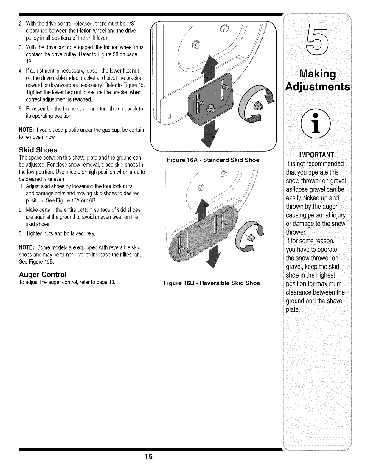
Skid Shoes
Thespacebetweenthisshaveplateandthegroundcan
be adjusted.Forclosesnowremoval,placeskidshoesin
thelowposition.Usemiddleorhighpositionwhenareato
be clearedis uneven.
1.Adjustskidshoesbylooseningthefourlocknuts
andcarriageboltsand movingskid shoestodesired
position.SeeFigure16Aor 16B.
2. Makecertaintheentirebottomsurfaceofskidshoes
areagainstthegroundtoavoidunevenwearon the
skidshoes.
3. Tightennutsandboltssecurely.
NOTE: Somemodelsareequippedwith reversibleskid
shoesandmaybeturnedoverto increasetheirlifespan.
See Figure16B.
Auger Control
Toadjusttheaugercontrol,referto page13.
Figure 16A- Standard Skid Shoe
//"
/
Figure 16B - Reversible Skid Shoe
IMPORTANT
It is notrecommended
that you operatethis
snowthrower on gravel
as loosegravelcan be
easilypicked up and
thrownby theauger
causingpersonalinjury
ordamageto thesnow
thrower.
Iffor some reason,
you haveto operate
thesnowthroweron
_ravel keepthe skid
shoe inthe highest
)ositionfor maximum
clearancebetweenthe
groundand the shave
)late.
15
:WARNING
i
oradjustment on
Avoid oilspillageon
rubberfrictionwheel
and aluminumdrive
plate:
Do not overfillthegear
casel Damageto the
sealscould result.
,_ WARNING:Alwayswearsafety
glassesduringoperationorwhile
performinganyadjustmentsor
repairs.
Engine
Refertotheseparateenginemanualpackedwithyour
unitforall enginemaintenance.
Lubrication
Gear (Hex) Shaft
Oncea season,lubricatethe hexshaftwitha penetrat-
ingoil,butnotgrease. RefertoFigure17.
Wheels
Atleastoncea season,removebothwheels.Cleanand
coattheaxleswitha multipurposeautomotivegrease
beforereinstallingwheels.
Auger Shaft
Atleastoncea season,removetheshearpinson auger
shaft.Spraylubricantinsideshaft,aroundthe spacers.
Alsolubricatetheflangebearingsfoundateitherendof
theshaft.SeeFigure24.
Gear Case
Theaugergearcasehasbeenfilledwithgreaseat
thefactory.If disassembledforanyreason,lubricate
withtwoouncesofgrease(PartNumber737-0168).
Beforereassembling,removeoldsealantandapplynew
sealant.
NOTE:Donotoverfillthegearcase.Damagetothe
sealscouldresult.Besuretheventplugisfreeof
greasein orderto relievepressure.
Drive Mechanism
Removerearcover.Oilanychains,sprockets,gears,
bearings,shafts,andshiftingmechanismat leastonce
a season.Useengineoilor a spraylubricant.Avoid
gettingoil on rubberfrictionwheelandaluminumdrive
plate.
Engine
Refertotheseparateenginemanualpackedwithyour
unitforall enginelubricationinstructions.
Drive/Auger Control Lock
Thecamon theendsofthecontrolrodswhichinterlock
thedriveandaugercontrolsmustbelubricatedatleast
oncea seasonorevery25hoursofoperationusing
a multi-purposeautomotivegrease.Thecamcanbe
accessedbeneathhandlepanel.
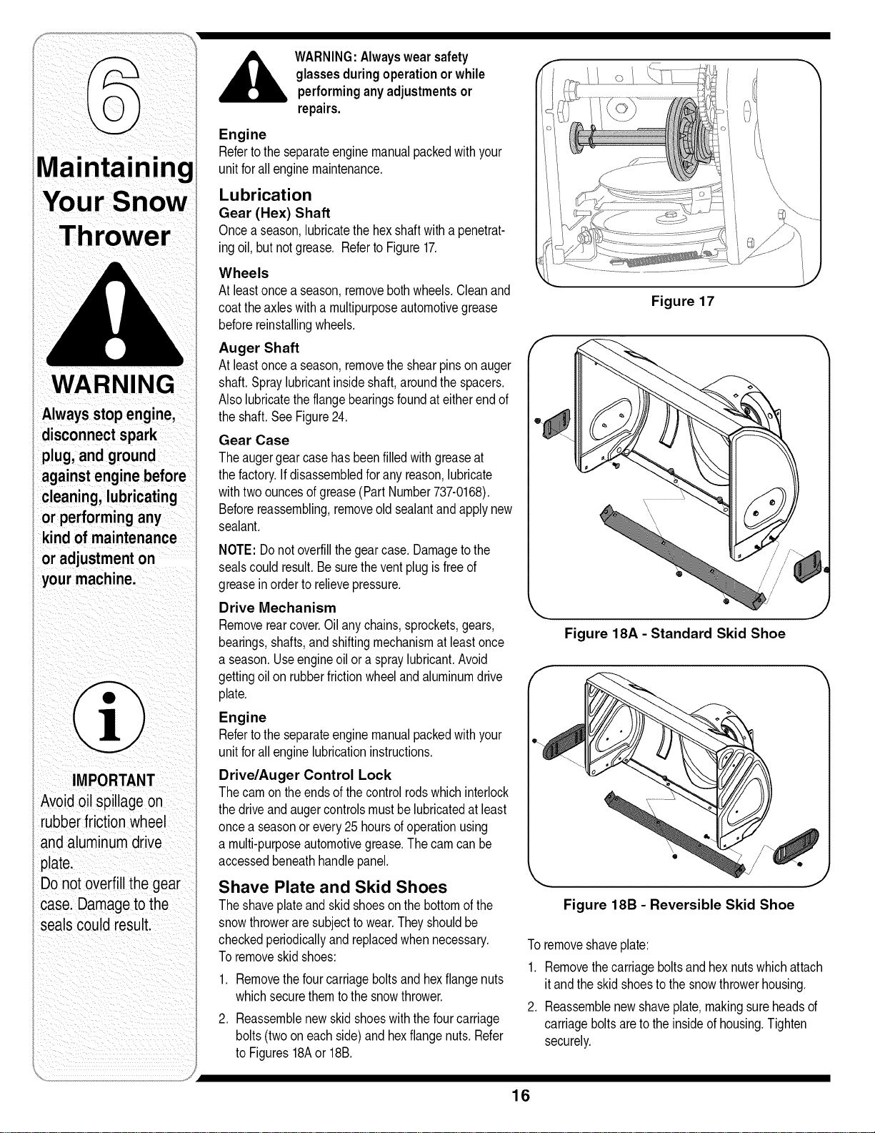
Shave Plate and Skid Shoes
Theshaveplateand skidshoesonthebottomofthe
snowthroweraresubjecttowear.Theyshouldbe
checkedperiodicallyandreplacedwhennecessary.
Toremoveskidshoes:
1. Removethefourcarriageboltsandhexflangenuts
whichsecurethemtothesnowthrower.
2. Reassemblenewskidshoeswiththefourcarriage
bolts(twooneachside)andhexflangenuts.Refer
toFigures18Aor 18B.
Figure 17
Figure 18A- Standard Skid Shoe
Figure 18B - Reversible Skid Shoe
Toremoveshaveplate:
1. Removethecarriageboltsand hexnutswhichattach
itandtheskidshoesto thesnowthrowerhousing.
2. Reassemblenewshaveplate,makingsureheadsof
carriageboltsaretotheinsideofhousing.Tighten
securely.
16
f
!
Figure 19
,J
Figure 20
Figure 21
Figure 22
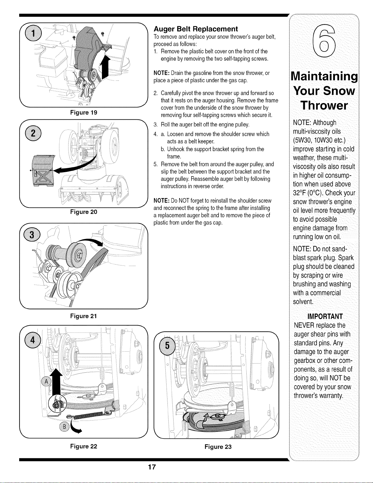
Auger Belt Replacement
Toremoveandreplaceyoursnowthrower'saugerbelt,
proceedasfollows:
1. Removethe plasticbeltcoveronthefrontofthe
enginebyremovingthetwoself-tappingscrews.
NOTE:Drainthegasolinefromthesnowthrower,or
placea pieceofplasticunderthegascap.
2. Carefullypivotthesnowthrowerup andforwardso
thatit restson theaugerhousing.Removetheframe
coverfromtheundersideofthesnowthrowerby
removingfourself-tappingscrewswhichsecureit.
3. Rolltheaugerbeltoff theenginepulley.
4. a. Loosenand removetheshoulderscrewwhich
actsasa beltkeeper.
b. Unhookthesupportbracketspringfromthe
frame.
5. Removethe beltfromaroundtheaugerpulley,and
slipthe beltbetweenthesupportbracketandthe
augerpulley.Reassembleaugerbeltbyfollowing
instructionsin reverseorder.
NOTE:DoNOTforgettoreinstalltheshoulderscrew
andreconnectthespringtotheframeafterinstalling
a replacementaugerbeltandto removethepieceof
plasticfromunderthegascap.
Figure 23
Maintaining
Your Snow
Thrower
NOTE:Although
multi-viscosityoils
(5W30,10W30etc.)
improvestarting in cold
weather,thesemulti-
viscosity oils also result
in higher oilconsump-
tion when usedabove
32°F(0°C). Checkyour
snow thrower'sengine
oil level morefrequently
to avoidpossible
enginedamagefrom
runninglowonoil.
NOTE: Donot sand-
blastspark plug.Spark
plugshould becleaned
byscraping or w=re
brushingandwashing
with a commercial
solvent.
IMPORTANT
NEVER replacethe
_ugershear pinswith
standardpins.Any
damageto theauger
gearboxor other com-
3onents,as a resultof
doing so,will NOTbe
coveredby yoursnow
thrower'swarranty.
17
;now
WARNING
Alwaysstop engine,
disconnectspark
plug, and ground
against enginebefore
cleaning,lubricating
or doing any kind
of maintenanceor
adjustments on your
_machine.
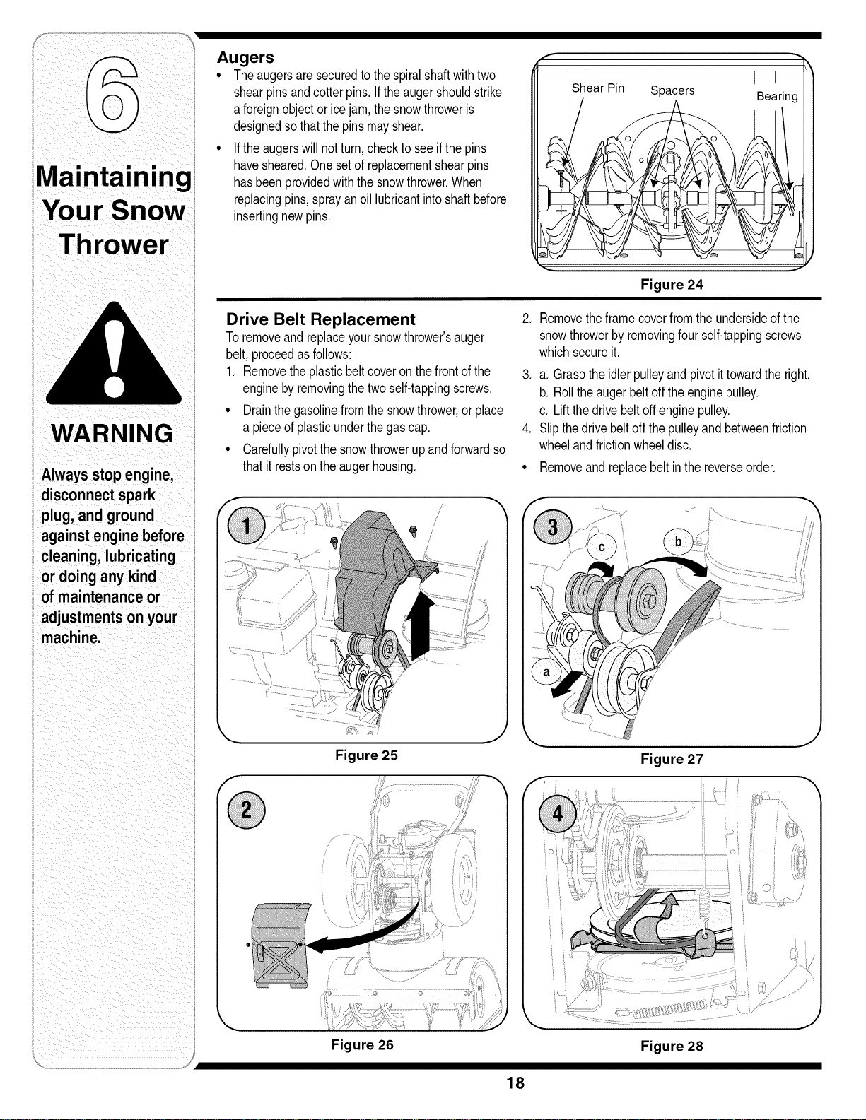
Augers
. Theaugersaresecuredtothespiralshaftwithtwo
shearpinsandcotterpins,If theaugershouldstrike
a foreignobjector icejam,thesnowthroweris
designedsothatthepinsmayshear,
• If theaugerswillnotturn,checkto seeifthepins
havesheared,Onesetof replacementshearpins
hasbeenprovidedwiththesnowthrower.When
replacingpins,sprayanoil lubricantintoshaftbefore
insertingnewpins,
Pin Spacers
I
Bearing
Figure 24
Drive Belt Replacement 2,
Toremoveand replaceyoursnowthrower'sauger
belt,proceedasfollows:
1, Removetheplasticbeltcoveronthefrontofthe
enginebyremovingthetwo self-tappingscrews.
° Drainthegasolinefromthesnowthrower,or place
a pieceof plasticunderthegascap,
° Carefullypivotthesnowthrowerupandforwardso
that itrestson theaugerhousing. °
Removetheframecoverfromtheundersideofthe
snowthrowerbyremovingfourself-tappingscrews
whichsecureit,
3, a, Grasptheidlerpulleyandpivotittowardtheright.
b, Rolltheaugerbeltoff theenginepulley.
c, Liftthedrivebeltoffenginepulley.
4, Slipthedrivebeltoff thepulleyandbetweenfriction
wheelandfrictionwheeldisc.
Removeandreplacebeltinthe reverseorder.
Figure 25
in
/
\ J
fi s
Figure 27
Figure 26
Figure 28
18
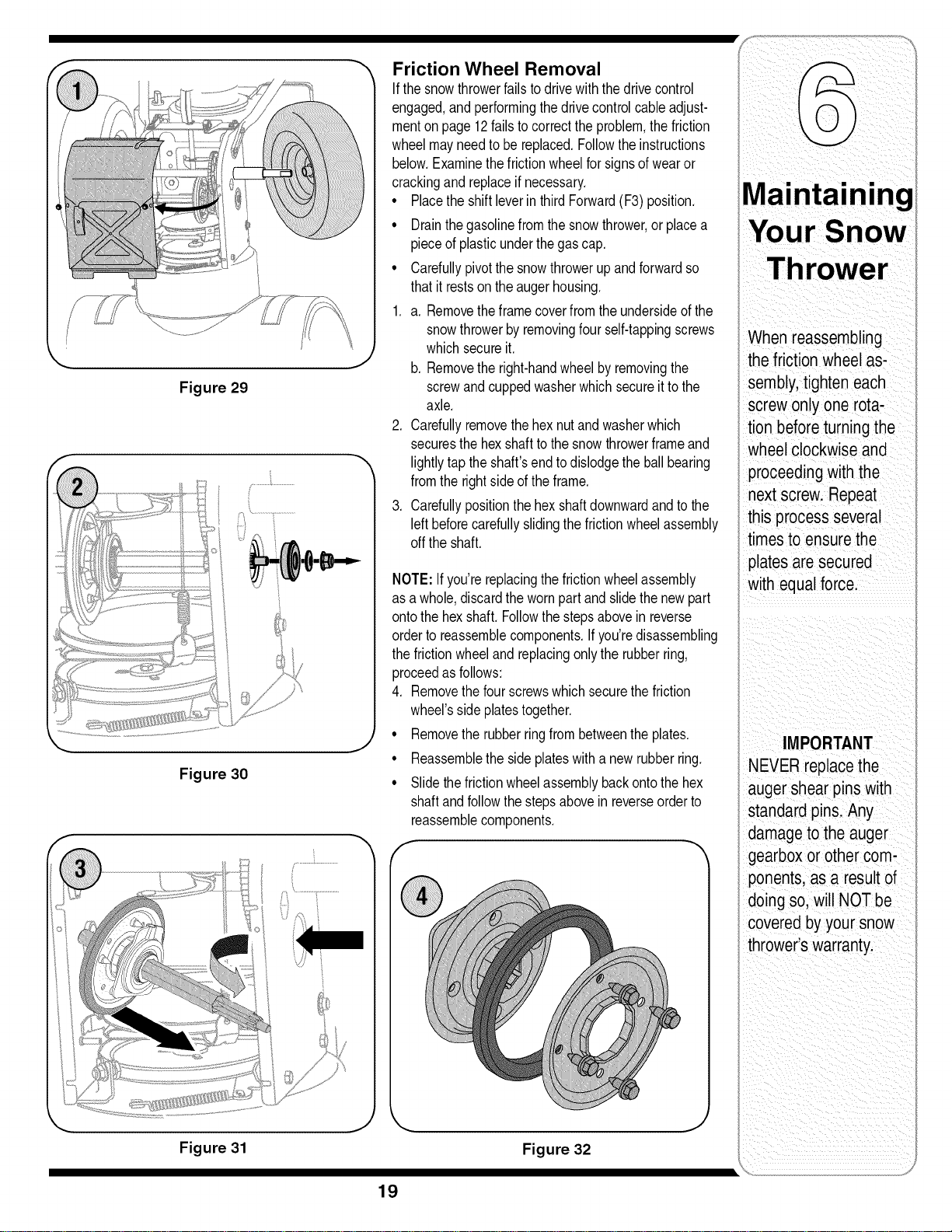
Figure 29
Figure 30
Figure 31
J
Friction Wheel Removal
If thesnowthrowerfailstodrivewiththedrivecontrol
engaged,and performingthedrivecontrolcableadjust-
menton page12failsto correcttheproblem,thefriction
wheelmayneedtobe replaced.Followtheinstructions
below.Examinethefrictionwheelforsignsofwearor
crackingandreplaceifnecessary.
• PlacetheshiftleverinthirdForward(F3)position.
• Drainthegasolinefromthesnowthrower,or placea
pieceofplasticunderthegascap.
• Carefullypivotthesnowthrowerupandforwardso
thatit restson theaugerhousing.
1. a. Removetheframecoverfromtheundersideofthe
snowthrowerbyremovingfourself-tappingscrews
whichsecureit.
b. Removethe right-handwheelbyremovingthe
screwandcuppedwasherwhichsecureittothe
axle.
2. Carefullyremovethehexnutandwasherwhich
securesthehexshafttothesnowthrowerframeand
lightlytaptheshaft'sendtodislodgetheballbearing
fromthe rightsideoftheframe.
3. Carefullypositionthehexshaftdownwardandtothe
leftbeforecarefullyslidingthefrictionwheelassembly
offtheshaft.
NOTE:Ifyou'rereplacingthefrictionwheelassembly
asa whole,discardthewornpartand slidethenewpart
ontothehexshaft.Followthestepsabovein reverse
orderto reassemblecomponents.Ifyou'redisassembling
thefrictionwheeland replacingonlytherubberring,
proceedasfollows:
4. Removethefourscrewswhichsecurethefriction
wheel'ssideplatestogether.
• Removethe rubberringfrombetweentheplates.
• Reassemblethesideplateswitha newrubberring.
• Slidethefrictionwheelassemblybackontothehex
shaftandfollowthestepsabovein reverseorderto
reassemblecomponents.
f
J _, J
Figure 32
Maintaining
Your Snow
Thrower
When reassembling
the frictionwheelas-
sembly,tighten each
screw onlyone rota-
tion beforeturning the
wheelclockwise and
proceedingwith the
nextscrew. Repeat
this processseveral
timesto ensurethe
platesare secured
with equalforce.
IMPORTANT
NEVERreplacethe
auger shearpins with
standardpins. Any
damageto the auger
gearboxor other com-
ponents,as a resultof
doing so,will NOTbe
covered byyour snow
thrower'swarranty.
19
WARNING
Neverstore snow
thrower with fuel
intank indoors or
in poorlyventilated
areas, where fuel
fumes may reach an
openflame, spark
or pilot lightason a
furnace, water heater,
clothes dryer or gas
appliance.
Drainfuel intoan
approved container
outdoors,awayfrom
any open flame. Be
certain engineis
cool. Do not smoke.
Fuel leftin engine
duringwarm weather
deterioratesand will
cause serious
starting problems.
Do notdrain
carburetor if
usingfuel stabilizer.
Never useengineor
carburetor cleaning
products inthe fuel
tank or permanent
damage may occur.
Observethefollowing,whenpreparingyoursnowthrower
foroff-seasonstorage:
* Drainfuelintoanapprovedcontaineroutdoors,away
fromanyopenflame.Allowenginetocool. Extinguish
cigarettes,cigars,pipesandothersourcesof ignition
priorto drainingfuel.Fuelleft inengineduringwarm
weatherdeterioratesandwillcauseseriousstarting
problems.
* If unitisto bestoredover30 days,prepareforstorage
as instructedin theseparateenginemanualpacked
with yourunit.
* Runengineuntilfueltankisemptyandenginestops
due tolackoffuel.
• Removegasolinefromcarburetorandfueltankto
preventgumdepositsfromformingon thesepartsand
causingpossiblemalfunctionofengine.
• Draincarburetorbypressingupwardon bowldrain,
locatedbelowthecarburetorcover.
* Fuelstabilizers,suchasSTA-BIL®,areanacceptable
alternativein minimizingtheformationoffuelgum
depositsduringstorage.Donotdraincarburetorif
usinga fuelstabilizer.
* Wipeequipmentwithanoiledragtopreventrust.
* Removesparkplugandpourone ounceofengineoil
throughsparkplugholeintocylinder.Coversparkplug
holewith rag.Crankengineseveraltimestodistribute
oil. Replacesparkplug.
* Followthelubricationrecommendationsfoundinthe
MaintenanceSection.
* Alwaysstorethesnowthrowerina clean,dryarea.
20
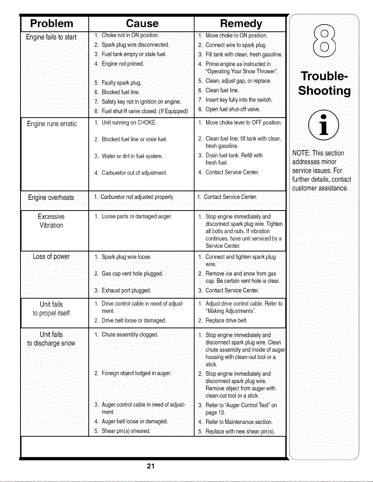
Problem Cause Remedy
Enain failsto t rt ChokenotnONposton MovechoketoONposton
e sa :
2. Sparkplugwiredisconnected, 2. Connectwiretosparkplug.
3 FueltankemptyorStalefuel. 31 Fi!!tankwithclean,freshgasoiinel
Engine notprimed, 41 ,Primeengineasinstructedin
OpeiatingYourSnowTh[owe[
5 Faulty sparkplug 5. Clean, adjustgap,or replace.
&Blocked fUellinel 6. Clean fuelline,
7: Safetykeynotin ignitionon enginel 7_Insert keyfu!lyintothe switch.
81Fue! shuFffValveClose&(If EquiPped)Open fuelshut,offValve,
Engineruns erratic 1. UnitrunningonCHOKE. 1. MovechokelevertoOFFposition.
2. Blockedfuellineor stalefuel.
3. Waterordirt infuelsystem.
4. Carburetoroutofadjustment.
2. Cleanfuelline;fill tankwithclean,
freshgasoline.
3. Drainfueltank.Refillwith
freshfuel.
4. ContactServiceCenter.
Engine overheats i carburetoi notadjustedproper!yl ii c0ntact serviCeCenteil
Excessive 1. Loosepartsordamagedauger. 1. Stopengineimmediatelyand
Vibration disconnectsparkplugwire.Tighten
all boltsandnuts.If vibration
continues,haveunitservicedbya
ServiceCenter.
Lossof power 1. Sparkp ugw re oose. 1. Connectandtightensparkplug
wire.
2 Gascapventholepugged. 2 Removeiceandsnowfromgas
. 3. Exhaustportplugged. 3. ContactServiceCenter.
Unitfails 1. Drivecontrolcablein needofadjust- 1. Adjustdrivecontrolcable.Referto
to propelitself ment. "MakingAdjustments".
2. Drivebeltlooseor damaged. 2. Replacedrivebelt.
Unitfails , 1. Chuteassemblyclogged.
1. Stopengineimmediatelyand
3. Augercontrolcableinneedofadjust- 3 Referto "AugerContro Test"on
ment. page13.
4 Augerbet ooseor damaged 4. Referto Mantenancesecton
5. Shearpin(s)sheared. 5. Replacewithnewshearpin(s).
NOTE This section
addresses minor
service issues.For
further details,
customer assistancel
21
MANUFACTURER'S LIMITED WARRANTY
ThelimitedwarrantysetforthbelowisgivenbyMTDLLCwithrespect
tonewmerchandisepurchasedandusedin theUnitedStatesand/orits
territoriesandpossessions,andbyMTDProductsLimitedwithrespectto
newmerchandisepurchasedandusedin Canadaand/oritsterritoriesand
possessions(eitherentityrespectively,"MTD").
MTDwarrantsthisproduct(excludingits normalwearpartsasdescribed
below)againstdefectsinmaterialandworkmanshipfora periodoftwo
(2) yearscommencingon thedateoforiginalpurchaseandwill,at its
option,repairor replace,freeofcharge,anypartfoundtobe defective
in materialsor workmanship.Thislimitedwarrantyshallonlyapplyif
thisproducthasbeenoperatedand maintainedin accordancewiththe
Operator'sManualfurnishedwiththeproduct,and hasnotbeensubjectto
misuse,abuse,commercialuse,neglect,accident,impropermaintenance,
alteration,vandalism,theft,fire,water,or damagebecauseofotherperilor
naturaldisaster.Damageresultingfromtheinstallationor useofanypart,
accessoryorattachmentnotapprovedbyMTDforusewiththeproduct(s)
coveredbythismanualwillvoidyourwarrantyastoanyresultingdamage.
Normalwearpartsarewarrantedto befreefromdefectsinmaterialand
workmanshipfora periodofthirty(30)daysfromthedateof purchase.
Normalwearpartsinclude,butare notlimitedto itemssuchas: batteries,
belts,blades,bladeadapters,grassbags,riderdeckwheels,seats,snow
throwerskidshoes,frictionwheels,shaveplates,augerspiralrubberand
tires.
HOWTOOBTAINSERVICE:Warrantyserviceisavailable,WITH
PROOFOFPURCHASE,throughyourlocalauthorizedservicedealer.To
locatethedealerin yourarea;
Inthe U.S.A.:
CheckyourYellowPages,or contactMTDLLCat EO.Box361131,
Cleveland,Ohio44136-0019,orcall1-800-800-7310or 1-330-220-4683
or logontoourWebsiteat www.mtdproducts.com.
In Canada:
ContactMTDProductsLimited,Kitchener,ONN2G4J1,or call1-800-
668-1238or logon toourWebsiteatwww.mtdcanada.com.
Thislimitedwarrantydoesnotprovidecoveragein thefollowingcases:
a. Theengineor componentpartsthereof.Theseitemsmaycarrya
separatemanufacturer'swarranty.Refertoapplicablemanufacturer's
warrantyfortermsand conditions.
b. Logsplitterpumps,valves,andcylindershavea separateone-year
warranty.
c. Routinemaintenanceitemssuchaslubricants,filters,blade
sharpening,tune-ups,brakeadjustments,clutchadjustments,deck
adjustments,andnormaldeteriorationoftheexteriorfinishdueto use
orexposure.
d. Servicecompletedbysomeoneotherthananauthorizedservice
dealer.
e. MTDdoesnotextendanywarrantyforproductssoldor exported
outsideofthe UnitedStatesand/orCanada,andtheirrespectivepos-
sessionsandterritories,exceptthosesoldthroughMTD'sauthorized
channelsofexportdistribution.
f. ReplacementpartsthatarenotgenuineMTDparts.
g. Transportationchargesand servicecalls.
h. If Productsare usedcommercially.(MTDmayseparatelyoffer Limited
CommercialWarrantiesoncertainselectproducts.Askyourdealeror
retailerfordetailsorcontactMTDServiceformoreinformation.)
No implied warranty, including anyimplied warranty of merchant-
ability of fitness for a particular purpose, applies after the applicable
period of expresswritten warranty aboveas to the partsas identi-
fied. Noother expresswarranty, whether written or oral, exceptas
mentioned above,given by anyperson or entity, including adealer
or retailer, with respect to anyproduct, shall bind MTD.Duringthe
period of the warranty, the exclusive remedy is repair or replacement
of the product as set forth above.
Theprovisionsas setforthin thiswarrantyprovidethe soleand
exclusiveremedyarisingfrom thesale.MTDshallnot beliable
for incidentalorconsequentiallossor damageincluding,without
limitation,expensesincurredfor substituteorreplacementlawncare
servicesor for rentalexpensestotemporarilyreplacea warranted
product.
Somejurisdictionsdo notallowtheexclusionorlimitationof incidentalor
consequentialdamages,or limitationson howlonganimpliedwarranty
lasts,sotheaboveexclusionsor limitationsmaynotapplytoyou.
Innoeventshallrecoveryofanykindbegreaterthantheamountofthe
purchasepriceoftheproductsold.Alteration of safety features of the
product shallvoid this warranty. Youassumetheriskandliabilityfor
loss,damage,or injurytoyouandyourpropertyand/ortoothersandtheir
propertyarisingoutofthemisuseor inabilitytousetheproduct.
Thislimitedwarrantyshallnotextendto anyoneotherthantheoriginal
purchaseror tothepersonforwhomitwaspurchasedasagift.
HOWLOCALLAWSRELATETOTHISWARRANTY:Thislimitedwar-
rantygivesyouspecificlegalrights,andyoumayalsohaveotherrights
thatvary indifferentjurisdictions.
IMPORTANT:OwnermustpresentOriginalProofof Purchasetoobtain
warrantycoverage.
MTD LLC, P.O.BOX 361131CLEVELAND,OHIO 44136-0019; Phone: 1-800-800-7310
MTD ProductsLtd.,P.O. BOX1386, KITCHENER,ON N2G 4J1; Phone: 1-800-668-1238
22
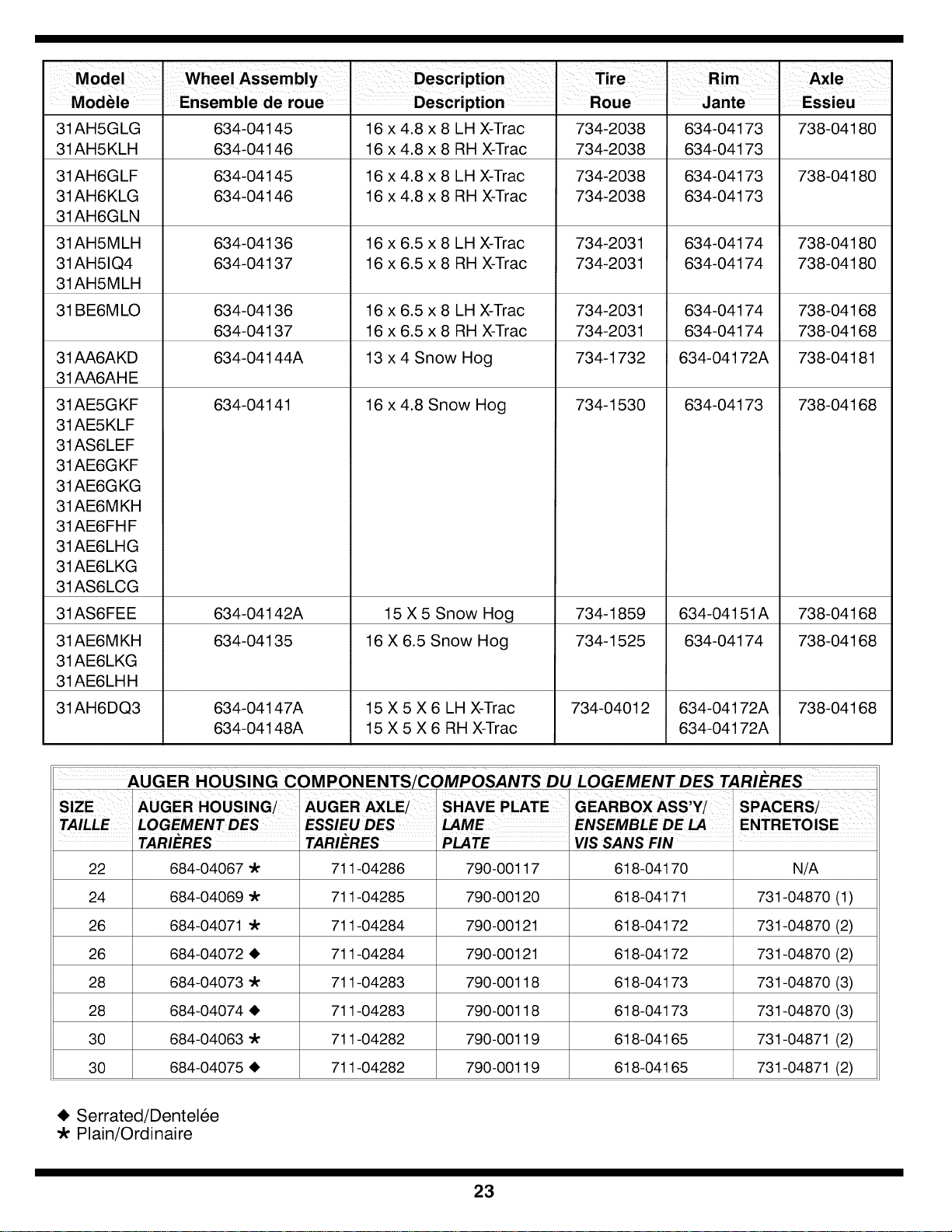
31AH5GLG 634-04145 16 x 4.8 x 8 LH X-Trac 734-2038 634-04173 738-041 80
31AH5KLH 634-04146 16 x 4.8 x 8 RH X-Trac 734-2038 634-04173
31AH6GLF 634-04145 16 x 4.8 x 8 LH X-Trac 734-2038 634-04173 738-041 80
31AH6KLG 634-04146 16 x 4.8 x 8 RH X-Trac 734-2038 634-04173
31AH6GLN
31AH5MLH 634-04136 16 x 6.5 x 8 LH X-Trac 734-2031 634-04174 738-041 80
31AH51Q4 634-04137 16 x 6.5 x 8 RH X-Trac 734-2031 634-04174 738-041 80
31AH5M LH
31BE6M LO 634-04136 16 x 6.5 x 8 LH X-Trac 734-2031 634-04174 738-04168
634-04137 16 x 6.5 x 8 RH X-Trac 734-2031 634-04174 738-04168
634-04144A 13 x 4 Snow Hog 734-1732 634-04172A 738-041 81
634-04141 16 x 4.8 Snow Hog 734-1530 634-04173 738-04168
31AA6AKD
31AA6AH E
31AE5G KF
31AE5KLF
31AS6LEF
31AE6G KF
31AE6G KG
31AE6M KH
31AE6FH F
31AE6LHG
31AE6LKG
31AS6LCG
31AS6FEE
31AE6M KH
31AE6LKG
31AE6LH H
31AH6DQ3
634-04142A
634-04135
634-04147A
634-04148A
15 X5 Snow Hog
16 X 6.5 Snow Hog
15 X 5 X 6 LH X-Trac
15 X 5 X 6 RH X-Trac
734-1859
734-1525
734-0401 2
634-04151A
634-04174
634-04172A
634-04172A
738-04168
738-04168
738-04168
AUGER HOUSING COMPONENTS/COMPOSANTS DU LOGEMENT DES TARI_cRES
TARIERES TARIERES PLATE VIS SANS FIN
22 684-04067 "k 711-04286 790-00117 618-04170 N/A
24 684-04069 "k 711-04285 790-00120 618-04171 731-04870 (1)
26 684-04071 "k 711-04284 790-00121 618-04172 731-04870 (2)
26 684-04072 • 711-04284 790-00121 618-04172 731-04870 (2)
28 684-04073 "k 711-04283 790-00118 618-04173 731-04870 (3)
28 684-04074 • 711-04283 790-00118 618-04173 731-04870 (3)
30 684-04063 "k 711-04282 790-00119 618-04165 731-04871 (2)
30 684-04075 • 711-04282 790-00119 618-04165 731-04871 (2)
_i, Serrated/Dentel6e
-k Plain/Ordinaire
23
\
/
/
,_4_
\ _J
24
REF PART
NO. NO.
N ° DE N° DE
REF PIECE
1 710-1652
2 731-05353
3 732-0708
4 711-1268B
5 746-04229
6 732-0209
7 790-00207
8 684-04156
9 750-04474
10 714-0126
11 710-0602
12 717-04210
13 712-04063
14 741-0245
15 790-00206
16 756-0625
17 738-0924
18 618-04288
18 618-04287
19 726-04012
20 750-04477
21 790-00156
22 732-04311
23 731-05297
24 716-0104
26 736-0188
26 736-0626
27 741-04076
28 738-04180
29 731-04873
30 710-0654A
31 710-0788
32 790-00185
33
34 736-0242
35 710-0627
36 684-04154
37 790-00096
38 748-0190
39 738-04184A
40 790-00226
41 656-04028
42 618-04283
42A 711-04416
42B 618-04284
42C 717-1209A
42D 736-0502
42E 736-0336
42F 717-1210A
42G 618-04285
42H 716-0194
43 684-04159
43A 735-04054
43B 790-00174
44 716-0136
45 726-0221
46 790-00183
47 756-04109
48 736-0505
49 710-1245B
50 736-0119
51 790-00230
52 741-0919
53 750-04571
54 732-04308A
55 710-0672
56 756-04179
57 754-04088
58 710-0809
59 790-00208
60 748-04112
61 732-0264
62 712-0413
63 750-04303
64 756-04113
65 736-0247
66 710-0191
67 748-04053
68 746-0956A
69 790-00186
70 750-0767
71 712-04065
72 754-04050
73 710-0751
74 790-00217
75 790-00218
76 712-04064
DESCRIPTION
Hex Wash Hd TT Scr. 1/4-20 x .625
Belt Cover
Cable Control Wire
Drive Shaft Actuator
Drive Clutch Cable 44.83" Lg.
Extension Spring .47 OD x 2.03 Lg.
Guide Bracket - Drive Cable
Shift Rod Ass'y
Axle Support Tube
#9 HI-Pro Key 3/16 x 3/4 Dia HT
Hex Wash Hd Tapp Scr 5/16-18 x 1.OO
Gear, 56T
Flange Lock-Nut 5/16-18 Gr. F Nylon
Hex. Flange Bearing.751" ID
Guide Bracket - Auger Cable
Cable Guide Roller
Hex Shld.Scr.1/4-28 x .375
Dogg Assembly - LH
Dogg Assembly - RH
Push Nut
Spacer .340 x .750 x .360" Lg.
Shift Spacer Bracket
Torsion Spring .750 ID x .968" Lg.
Spacer
Retaining Ring
Flat Washer .760 ID x 1.49 OD
Flat Washer .580 x 1.125 x .080
Ball Bearing
Axle
Spacer
Hex Wash HD Tap Scr 3/8-16 x .88
Hex Bolt 1/4-20 x 1.OO
Shaft Retainer - LH
See chart on page 23.
Cupped Washer .345 ID x .88 OD x .060
Hex L-Bolt 5/16-24 x .75 Gr. 5
Friction Wheel Support Brkt Ass'y
Auger Cable Guide Bracket
Spacer .513 ID x 1 .O
Shoulder Screw .373 x. 105:TT 1/4-20
Frame Cover
Friction Wheel Disc Assembly
Drive Shaft Assembly (w/o Friction Wheel Ass'y)
Hex Drive Shaft (500)
Planetary Carrier Ass'y
Gear 12T
Flat Washer .58 x 1.12 x .02
Flat Washer 5/8 ID x 1.O OD
Gear 18T
Ring Planetary Gear Ass'y (500)
Retaining Ring 1.56 diam.
Friction Wheel Assembly
Friction Wheel Rubber
Friction Plate
Retainer Ring
Cap Speed Nut 1/4 Rod
Wheel Drive Frame
Auger Pulley
Flat Washer .34 x 1.50 x .150
Hex Bolt 5/16-24 x 0.875
L-Wash 5/16 ID
Bearing Sleeve
Ball Bearing 20 x 47 x 14:6204:DS
Spacer
Torsion Spring .850 ID x .354" Lg.
Hex HD. Cap Scr. 5/16-24 x 1.25 Lg.
Pulley HalfL 1/4Vx 1.50D
Belt 33.0" Lg.
Hex Bolt 1/4-20 x 1.25
Wheel Drive Idler Bracket
Shoulder Spacer
Extension Spring 3/80D x 2.50
Jam L-Nut 5/8-18 Gr. 5 Nylon
Spacer .875 ID x 1.185 OD
Pulley Half
Flat Washer .40 ID x 1.25 OD x .160
Hex Screw 3/8-24 x 1.25
Pulley Adapter
Steering Cable
Shaft Retainer - RH
Axle Spacer
Flange Lock-Nut 3/8-16 Gr. F Nylon
Belt .5 x 35.0" Lg.
Hex Bolt 1/4-20 x .62 Gr. 5
Pivot Bracket
Shift Bracket
Flange Lock-Nut 1/4-20 Gr. F Nylon
DESCRIPTION
Vis taraudee 1/4-20 x 0,625
Couvre-courroie
Fil de commande de la c&ble
Regulateur
C&ble de I'entra_nement 44,83 pc de Ig.
Ressort d'extension 0,47 DE x 2,03 pc de Ig.
Support - c&ble de I'entra_nement
Tige de changement de la vitesses
Tuyau de support de I'essieu
Clavette HI-Pro no. 9 - 3/16 x 3/4 dia.
Vis auto-fileteuse & t6te hex et rondelle 5/16-18
Engrenage 56 dents
Contre-ecrou & embase 5/16-18Qual. F nylon
Roulement & bride a six pans 0,751 DI
Support - C&ble de tari_re
Guide du c&ble
Vis & epaulement 1/4-28 x 0,375
CG - cliquet
CD - cliquet
Ecrou a enfoncer
Entretoise 0,340 x 0,750 x 0,360 pc de Ig.
Support d'espacement
Ressort de torsion 0,750 DI x 0,968 pc de Ig.
Entretoise
Anneau de retenue
Rondelle plate 0,760 DI x 1,49 DE
Rondelle plate 0,580 x 1,125 x 0,080
Roulement a billes
Essieu
Entretoise
Vis autotaraudee 3/8-16 x 0,88
Vis & t6te hex. 1/4-20 x 1,OO
Retenue d'arbre CG
Voir tableau de la page 23.
Rondelle creuse 0,345 DI x 0,88 DE x 0,060
Boulon hex. 5/16-24 x 0,75 Qual. 5
Support de la roue du friction
Support, guide de la c&ble de la tari@e
Entretoise 0,513 DI x 1,O
Vis & epaulement 0,373 x 0,105:1/4-20
Couvercle
Disque de roue du friction
Arbre d'entra;nement (sans ensemble de la roue frottement)
Arbre d'entra;nement (500)
Porte-roue
Engrenage 12 dents
Rondelle plate 0,58 x 1,12 x 0,02
Rondelle plate 5/8 DI x 1,0 DE
Engrenage 18 dents
Ensemble de I'engrenage (500)
Bague de retenue 1,56 diam.
Ensemble de la roue de frottement
Roue du friction en caoutchouc
Plaque du friction
Bague de retenue
Chapeau & enfoncer
Ch&ssis de I'entra;nement de roue
Poulie de la tari_re
Rondelle plate 0,34 x 1,50 x 0,150
Boulon hex. 5/16-24 x 0,875
Rondelle frein 5/16 DI
Roulement
Roulement & billes 20 x 47 x 14:6204:DS
Entretoise
Ressort de torsion 0,850 DI x 0,354 pc de Ig.
Vis & t6te hexagonal 5/16-24 x 1,25 pc de Ig
Poulie, demi 1,5 DE
Courroie trapezofdale 33,0 pc de Ig.
Boulon hex. 1/4-20 x 1,25
Support
Entretoise epaul6e
Ressort d'extension 3/8 DE x 2,50
Ecrou de blocage 5/8-18 Qual. 5 Nylon
Entretoise 0,875 DI x 1,185 DE
Moitie poulie
Rondelle plate 0,40 DI x 1,25 DE x 0,160
Vis & t6te hexagonale 3/8-24 x 1,25
Adaptateur de la poulie
C&ble
Retenue d'arbre CD
Entretoise - essieu
Contre-ecrou & embase 3/8-16 Qual. F nylon
Courroie 0,5 x 35,0 pc de Ig.
Boulon hexagonale 1/4-20 x 0,62 Qual. 5
Support de pivot
Support de changement de la vitesses
Contre-ecrou & embase 1/4-20 Qual. F nylon
316-5003
7.21.05
25
1
jr
16
J
36
40
\
141
4
43
J
22
%.
9
17
"12
21
14
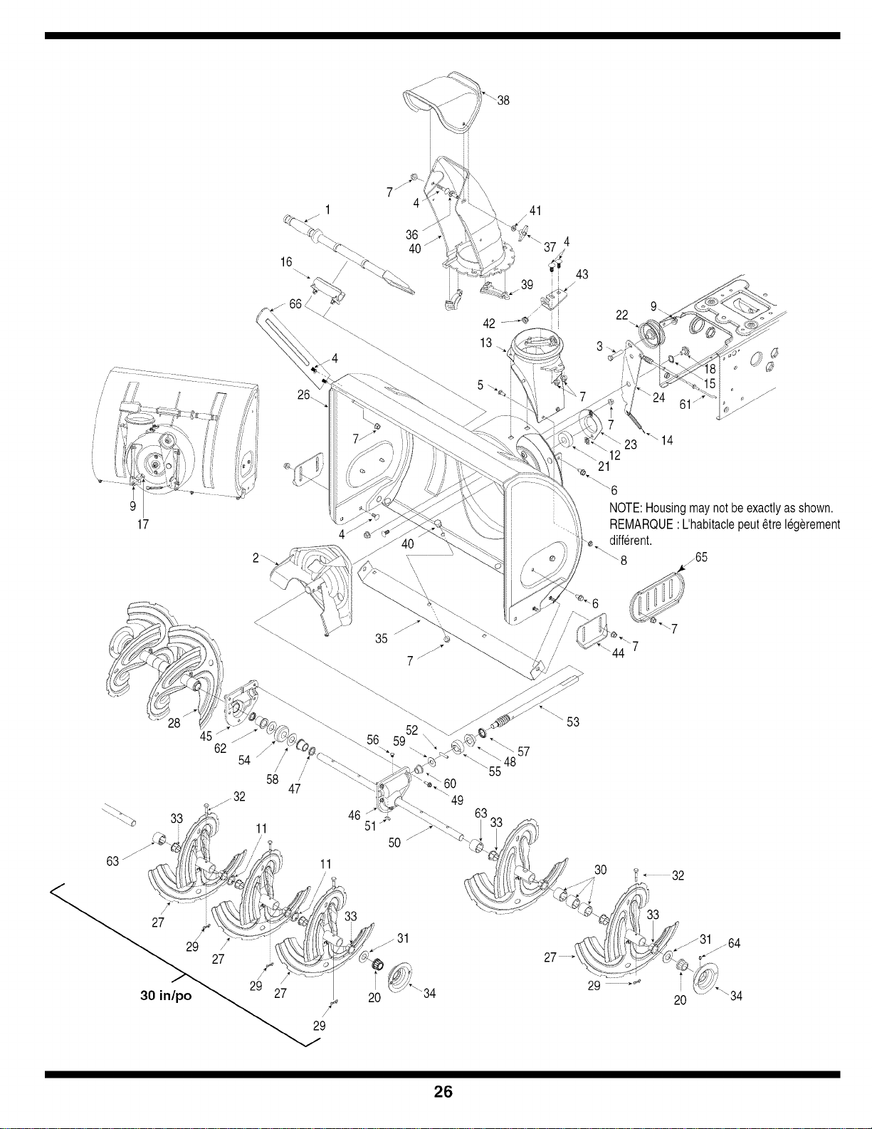
NOTE:Housing maynot be exactlyasshown.
REMARQUE' L'habitaclepeut_tre legerement
different.
/65
45 /_
62
54
/
/
58
47
11
46
51
56 5952
50
53
30
20
34
26

REF
NO.
N° DE
RI_F
1
2
3
4
5
6
7
8
9
10
11
12
13
14
15
16
17
18
19
20
21
22
23
24
25
26
27
28
29
30
31
32
33
34
35
36
37
38
39
40
41
42
43
44
45
46
47
48
49
5O
51
52
53
54
55
56
57
58
59
6O
61
62
63
64
65
66
PART
NO.
N° DE
PII_CE
731-2643
684-04057
710-0347
710-0451
710-0703
710-0604A
712-04063
712-04064
712-04065
714-0149B
731-04871
726-04012
731-04705
732-0611
736-0174
731-02625
738-0143
738-0281
738-04124A
741-0245
741-0309
756-0981A
790-00075
790-00080
684-04107
684-04108
714-04040
736-0188
738-04124A
741-0493A
790-00087A
790-00138A
710-04071
720-0284
731-04354A
731-04869
731-04912
736-0159
741-0475
784-5647
784-5580
719-0319
719-0320
721-0179
741-0662
710-0642
714-0161
715-04021
717-04126
717-0528A
718-04071
721-0325
721-0327
736-0351
736-3084
741-0663
746-0897
741-0661A
731-04870
737-3000
790-00091
790-00181
DESCRIPTION
Clean-Out Tool
Impeller Ass'y 12 po
Hex Screw 3/8-16 x 1.75
Carriage Bolt 5/16-18 x .75 Gr. 1
Carriage Screw 1/4-20 x .75 Gr. 5
Hex Wash HD AB Tap Scr 5/16-18 x .625
Flange Locknut 5/16-18 Gr. F Nylon
Hex L-Flanged Nut 1/4-20 Gr. F Nylon
Hex L-Flanged Nut 3/8-16 Gr. F Nylon
Internal Cotter Pin
Spacer 1.25 x .75 x 3/16" Lg.
Push-on Nut .25 dia.
Chute Adapter
Extension Spring
Wave Washer .660 ID x .88 OD x .010
Cleanout Tool Mount
Shld. Scr..500 Dia. x .335" Lg.
Shoulder Scr .625 Dia x .170
Shear Pin .25 x 1.5 Gr. 2
Hex. Flange Brg..751" I.D.
Self-aligning bearing
Flat Idler Pulley 2.75" OD
Bearing Housing 1.85 ID
Auger Idler Brake Bracket
See chart on page 23.
See chart on page 23.
Spiral Ass'y LH
Spiral Ass'y RH
Bow Tie Cotter Pin
See chart on page 23.
Flat Washer .760 ID x 1.49 OD
Shear Pin .25 x 1.5 Gr. 2
Flange Bushing
Bushing Housing
Bushing Housing (w/grease fitting hole)
See chart on page 23.
Carriage Bolt 5/16-18 x 1.0
Handle Knob Assembly
Upper Chute
Chute Flange Keeper
Lower Chute
Flat Washer .349 ID x .879 OD x .063
Plastic Bushing .380 ID
Chute Crank Brkt.
Slide Shoe
RH Reduced Auger Housing
LH Reduced Auger Housing
Oil Seal 3/4 ID
Flange Bearing .75 ID x 1.00 OD x .50
Thd Forming Scr. 1/4-20 x .75
See chart on page 23.
Hi Pro Key 3/16 x 5/8
Dowel Pin .25 OD x 1.2
Worm Shaft .75 OD
Worm Gear 20T
Thrust Collar
Plug, 1/4 x .437
Oil Seal .75x 1x .131
Flat Washer .76 ID x 1.50D x .03
FI. Washer .510 x 1.120 x .060
Flange Bearing .75 ID x 1.00D x .925
Auger Clutch Cable (w/"Z" fitting)
Flange Bearing.75 ID x 1.00D x .975
Spacer 1.25 x .75 x 1.00
Grease Fitting (optional)
Reversible Slide Shoe
Drift Cutter - Optional
DESCRIPTION
Outil de d6gagement de la goulotte
Ventilateur
Vis b,t_te hex 3/8-16 x 1,75
Boulon ordinaire 5/16-18 x 0,75 Qual. 1
Boulon ordinaire 1/4-20 x 0,75 Qual. 5
Vis taraud6e 5/16 x 0,625
Contre-6crou & embase 5/16-18 Qual. F nylon
Contre-6crou a embase 1/4-20 Qual. F nylon
Contre-ecrou a embase 3/8-16 Qual. F nylon
Goupille fendue interne
Entretoise 1,25 x 0,75 x 3/16 po de Ig.
E_croupousser 0,25 diam.
Adaptateur de goulotte d'6jection
Ressort d'extension
Rondelle ondul6e 0,660 DI x 0,88 DE x 0,010
Montage de la outil de d6gagement de la goulotte
Visa 6paulement dia. 0,500 pox 0,335 po de Ig.
Vis b,6paulement dia 0,625 x 0,170 po
Boulon de cisaillement 0,25 x 1,5 Qual 2.
Roulement 0,75 DI
Roulement auto-aligneur
Poulie tendeur 2,75 DE
Carter de la roulement 1,85 DI
Support
Voir tableau de la page 23.
Voir tableau de la page 23.
Tari@e CG
Tari@e CD
Goupille fendue
Voir tableau de la page 23.
Rondelle plate 0,760 DI x 1,49 DE
Goupille de cisaillement 0,25 x 1,5 po de Ig
Collet a bride
Carter de la collet
Carter de la collet (avec trou pour raccord de graissage)
Voir tableau de la page 23.
Boulon ordinaire 5/16-18 x 1,0
Bouton
Goulotte sup@ieur
Garde-bride de la goulotte
Goulotte inf@ieur
Rondelle plate 0,349 DI x 0,879 DE x 0,063
Manchon en plastique de 0,38 po de D.I.
Support du bras de goulotte d'ejection
Sabot coulissant
Carter de I'engrenage CD
Carter de I'engrenage CG
Joint d'etanch6it6 d'huile 3/4 DI
Roulement 0,75 DI x 1,00 DE x 0,50
Vis taraud6e 1/4-20 x 0,75
Voir tableau de la page 23.
Cl6 3/16 x 5/8
Goupille 0,25 x 1,2
Arbre 0,75 DE
Arbre 20 dents
Collet
Bouchon 1/4 x 0,437
Joint d'huile 0,75 DI x 1 x 0,131
Rondelle plate 0,76 DI x 1,5 DE x 0,03
Rondelle frein 0,510 x 1,120 x 0,060
Roulement 0,75 DI x 1,0 DE x 0,925
Cb,ble de tari@e (avec extr6mite en -Z_>)
Roulement 0,75 DI x 1,0 DE x 0,975
Entretoise 1,25 x 0,75 x 1,00 po de Ig.
Raccord de graissage (en option)
Patin r6versible
Virole de reglage - en option
31A-6002
7.12.05
27
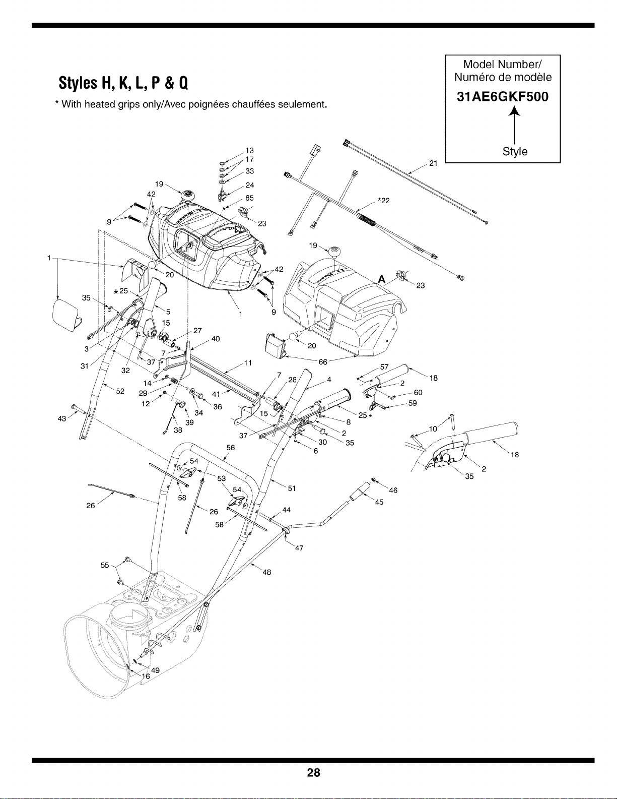
StylesH,K,L,P& Q
* With heated grips only/Avec poignees chauffees seulement.
4219
!
15
27
40
43
32
52
34
39
38
41
56
_11
7
44
Model Number/
Numero de modele
31AE6GKF500
Style
18
60
8
35
25 *
18
35
28
REF PART
NO. NO.
N° DE N° DE
REF PIECE
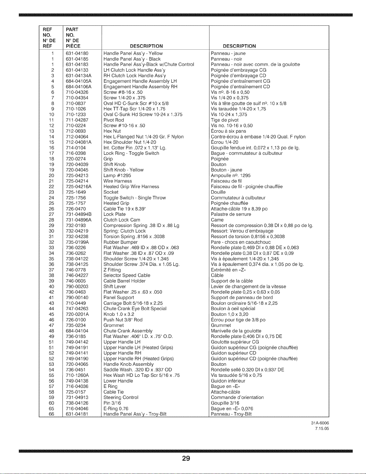
1 631-04180
1 631-04185
1 631-04183
2 631-04133
3 631-04134A
4 684-04105A
5 684-04106A
6 710-04326
7 710-04354
8 710-0837
9 710-1026
10 710-1233
11 711-04287
12 710-0224
13 712-0693
14 712-04064
15 712-04081A
16 714-0104
17 716-0398
18 720-0274
19 720-04039
19 720-04045
20 725-04213
21 725-04214
22 725-04216A
23 725-1649
24 725-1756
25 725-1757
26 726-0470
27 731-04894B
28 731-04896A
29 732-0193
30 732-04219
31 732-04238
32 735-0199A
33 736-0226
34 736-0262
35 738-04122
36 738-04125
37 746-0778
38 746-04227
39 746-0605
40 790-00203
42 736-0463
41 790-00140
43 710-0449
44 747-04263
45 720-0201A
46 726-0100
47 735-0234
48 684-04104
49 736-0185
51 749-04142
51 749-04191
52 749-04141
52 749-04190
53 720-04065
54 736-0451
55 710-1260A
56 749-04138
57 716-04036
58 725-0157
59 731-04913
60 738-04126
65 716-04046
66 631-04181
DESCRIPTION
Handle Panel Ass'y -Yellow
Handle Panel Ass'y - Black
Handle Panel Ass'y-Black w/Chute Control
LH Clutch Lock Handle Ass'y
RH Clutch Lock Handle Ass'y
Engagement Handle Assembly LH
Engagement Handle Assembly RH
Screw #8-16 x .50
Screw 1/4-20 x .375
Oval HD C-Sunk Scr #10 x 5/8
Hex TT-Tap Scr 1/4-20 x 1.75
Oval C-Sunk Hd Screw 10-24 x 1.375
Pivot Rod
Screw #10-16 x .50
Hex Nut
Hex L-Flanged Nut 1/4-20 Gr. F Nylon
Hex Shoulder Nut 1/4-20
Int. Cotter Pin .072 x 1.13" Lg.
Lock Ring - Toggle Switch
Grip
Shift Knob
Shift Knob - Yellow
Lamp #1295
Wire Harness
Heated Grip Wire Harness
Socket
Toggle Switch - Single Throw
Heated Grip
Cable Tie 19 x 8.39"
Lock Plate
Clutch Lock Cam
Compression Spring .38 ID x .88 Lg
Spring: Clutch Lock
Torsion Spring .8156 x .3038
Rubber Bumper
Flat Washer .469 ID x .88 OD x .063
Flat Washer .38 ID x .87 OD x .09
Shoulder Screw 1/4-20 x 1.345
Shoulder Screw .374 Dia. x 1.05 Lg.
Z Fitting
Selector Speed Cable
Cable Barrel Holder
Shift Lever
Flat Washer .25 x .63 x .050
Panel Support
Carriage Bolt 5/16-18 x 2.25
Chute Crank Eye Bolt Special
Knob 1.0 x 3.2
Push Nut 3/8" Rod
Grommet
Chute Crank Assembly
Flat Washer .406" I.D. x .75" O.D.
Upper Handle LH
Upper Handle LH (Heated Grips)
Upper Handle RH
Upper Handle RH (Heated Grips)
Handle Knob Assembly
Saddle Wash..320 ID x .937 OD
Hex Wash HD Lo Tap Scr 5/16 x .75
Lower Handle
E Ring
Cable Tie
Steering Control
Pin 3/16
E-Ring 0.76
Handle Panel Ass'y -Troy-Bilt
DESCRIPTION
Panneau - jaune
Panneau - noir
Panneau - noir avec comm. de la goulotte
Poign6e d'embrayage CG
Poign6e d'embrayage CD
Poign6e d'entrai'nement CG
Poign6e d'entrai'nement CD
Vis no. 8-16 x 0,50
Vis 1/4-20 x 0,375
Vis a t@e goutte de suif no. 10 x 5/8
Vis taraudee 1/4-20 x 1,75
Vis 10-24 x 1,375
Tige de pivot
Vis no. 10-16 x 0,50
Ecrou a six pans
Contre-ecrou a embase 1/4-20 Qual. F nylon
Ecrou 1/4-20
Goupille fendue int. 0,072 x 1,13 pc de Ig.
Bague - commutateur a culbuteur
Poign6e
Bouton
Bouton - jaune
Ampoulle no. 1295
Faisceau de fil
Faisceau de fil - poign6e chauff6e
Douille
Commutateur a culbuteur
Poignee chauff6e
Attache-c&ble 19 x 8,39 pc
Palastre de serrure
Came
Ressort de compression 0,38 DI x 0,88 pc de Ig.
Ressort: Verrou d'embrayage
Ressort de torsion 0,8156 x 0,3038
Pare - chocs en caoutchouc
Rondelle plate 0,469 DI x 0,88 DE x 0,063
Rondelle plate 0,38 DI x 0,87 DE x 0,09
Visa epaulement 1/4-20 x 1,345
Visa epaulement 0,374 dia. x 1,05 pc de Ig.
Extr6mit6 en -Z_>
C&ble
Support de la c&ble
Levier de changement de la vitesse
Rondelle plate 0,25 x 0,63 x 0,05
Support de panneau de bord
Boulon ordinaire 5/16-18 x 2,25
Boulon b,ceil special
Bouton 1,0 x 3,20
Ecrou pour tige de 3/8 pc
Grummet
Manivelle de la goulotte
Rondelle plate 0,406 DI x 0,75 DE
Goulotte sup@ieur CG
Guidon sup@ieur CG (poign6e chauff6e)
Guidon sup@ieur CD
Guidon sup@ieur CD (poignee chauffee)
Bouton
Rondelle sell6 0,320 DI x 0,937 DE
Vis taraud6e 5/16 x 0,75
Guidon inf@ieur
Bague en -E_>
Attache-c&ble
Commande d'orientation
Goupille 3/16
Bague en -E_>0,076
Panneau - Troy-Bilt
31A-6006
7.15.05
29
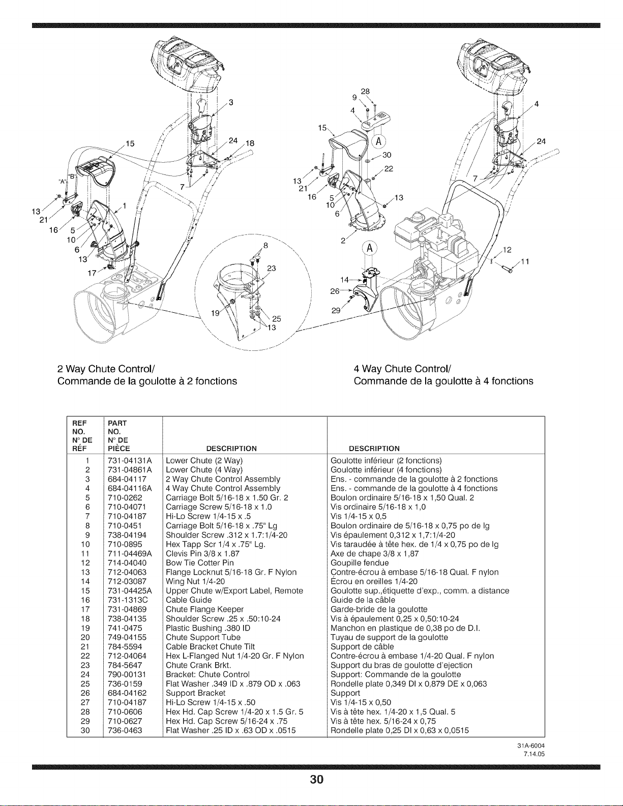
15
15\
28
\
4
\
13j
16
6 /
21
2 Way Chute Control/
Commande de la goulotte & 2 fonctions
4 Way Chute Control/
Commande de la goulotte & 4 fonctions
REF
NO.
N°DE
R_:F
1
2
3
4
5
6
7
8
9
10
11
12
13
14
15
16
17
18
19
20
21
22
23
24
25
26
27
28
29
30
PART
NO.
N°DE
PIECE
731-04131A
731-04861A
684-04117
684-04116A
710-0262
710-04071
1710-04187
710-0451
738-04194
710-0895
711-04469A
714-04040
712-04063
712-03087
731-04425A
731-1313C
731-04869
738-04135
741-0475
749-04155
784-5594
712-04064
784-5647
790-00131
736-0159
684-04162
710-04187
710-0606
710-0627
736-0463
DESCRIPTION
Lower Chute (2 Way)
Lower Chute (4 Way)
2 Way Chute Control Assembly
4 Way Chute Control Assembly
Carriage Bolt 5/16-18 x 1.50 Gr. 2
Carriage Screw 5/I 6-18 x 1.0
Hi-Lo Screw 1/4-15 x .5
Carriage Bolt 5/16-18 x .75" Lg
Shoulder Screw .312 x 1.7:1/4-20
Hex Tapp Scr 1/4 x .75" Lg.
Clevis Pin 3/8 x 1.87
Bow Tie Cotter Pin
Flange Locknut 5/16-18 Gr. F Nylon
Wing Nut 1/4-20
Upper Chute w/Export Label, Remote
Cable Guide
Chute Flange Keeper
Shoulder Screw .25 x .50:10-24
Plastic Bushing .380 ID
Chute Support Tube
Cable Bracket Chute Tilt
Hex L-Flanged Nut 1/4-20 Gr. F Nylon
Chute Crank Brkt.
Bracket: Chute Control
Flat Washer .349 ID x .879 OD x .063
Support Bracket
Hi-Lo Screw 1/4-15 x .50
Hex Hd. Cap Screw 1/4-20 x 1.5 Gr. 5
Hex Hd. Cap Screw 5/16-24 x .75
Flat Washer .25 ID x .63 OD x .0515
DESCRIPTION
Goulotte inf6rieur (2 fonctions)
Goulotte inf6rieur (4 fonctions)
Ens. - commande de la goulotte a 2 fonctions
Ens. - commande de la goulotte a 4 fonctions
Boulon ordinaire 5/16-18 x 1,50 Qual. 2
Vis ordinaire 5/16-18 x 1,0
Vis 1/4-15 x 0,5
Boulon ordinaire de 5/16-18 x 0,75 po de Ig
Vis epaulement 0,312 x 1,7:1/4-20
Vis taraud6e a t6te hex. de 1/4 x 0,75 po de Ig
Axe de chape 3/8 x 1,87
Goupille fendue
Contre-6crou b.embase 5/16-18 Qual. F nylon
Ecrou en oreilles 1/4-20
Goulotte sup.,6tiquette d'exp., comm. a distance
Guide de la c&ble
Garde-bride de la goulotte
Visa epaulement 0,25 x 0,50:10-24
Manchon en plastique de 0,38 po de D.I.
Tuyau de support de la goulotte
Support de c&ble
Contre-ecrou a embase 1/4-20 Qual. F nylon
Support du bras de goulotte d'ejection
Support: Commande de la goulotte
Rondelle plate 0,349 DI x 0,879 DE x 0,063
Support
Vis 1/4-15 x 0,50
Vis a t6te hex. 1/4-20 x 1,5 Qual. 5
Visa t6te hex. 5/16-24 x 0,75
Rondelle plate 0,25 DI x 0,63 x 0,0515
31A-6004
7.14.05
3O