Shenzhen Xtooltech Intelligent Co., LTD
User Manual
D8 BT Smart Diagnosis System

I
Please read this user manual carefully before using the D8 BT Smart
Diagnosis System. When reading the manual, please pay attention to the
words “Note” or “Caution”, and read them carefully for appropriate operation.
TRADEMARKS
is a registered trademark of Shenzhen Xtooltech Intelligent
CO., LTD.
In countries where the trademarks, service marks, domain names, logos and
the name of the company are not registered, Xtool claims that it still reserves
the ownership of the unregistered trademarks, service marks, domain names,
logos and the company name. All other marks for the other products and the
company’s name mentioned in the manual still belong to the original
registered company.
You may not use the trademarks, service marks, domain names, logo and
company name of Xtool or other companies mentioned without written
permission from the trademark holder.
Xtool reserves the right to the final interpretation of this manual content.
COPYRIGHT
Without the written consent of Shenzhen Xtooltech Intelligent Co., Ltd., any
company or individual shall not copy or backup this operation manual in any
form (electronic, mechanical, photocopying, recording or other forms).

II
DECLARATION
This manual is designed for the usage of the D8 BT Smart Diagnosis System
and provides operating instructions and product descriptions for users of the
D8 BT Smart Diagnostic system.
No part of this manual can be reproduced, stored in a retrieval system or
transmitted, in any form or by any means (electronic, mechanical,
photocopying, recording, or otherwise), without the prior written permission
of Xtool.
Use the device only as described in this manual. Xtool is not responsible for
any consequences of violating the laws and regulations caused by using the
product or its data information
Xtool shall not be liable for any incidental or consequential damages or for
any economic consequential damages arising from the accidents of
individual users and the third parties, misuse or abuse of the device,
unauthorized change or repair of the device, or the failure made by the user
not to use the product according to the manual.
All information, specifications and illustrations in this manual are based on
the latest configurations and functions available at the time of printing. Xtool
reserves the right to make changes at any time without notice.
OPERATION INSTRUCTIONS
For safe operation, please follow the instructions below:
⚫ Keep the device away from heat or fumes when you use it.
⚫ If the vehicle battery contains acid, please keep your hands and skin or
fire sources away from the battery during testing.
⚫ The exhaust gas of the vehicle contains harmful chemicals, please
ensure adequate ventilation.

III
⚫ Do not touch the cooling system components or exhaust manifolds
when the engine is running due to the high temperatures reached.
⚫ Make sure the car is securely parked, Neutral is selected or the selector
is at P or N position to prevent the vehicle from moving when the engine
starts.
⚫ Do not switch off the power or unplug the connectors during testing,
otherwise, you may damage the ECU and/or the Diagnostic Tablet.
CAUTIONS!
⚫ Avoid shaking or dismantling the unit as it may damage the internal
components.
⚫ Do not use hard or sharp objects to touch the LCD screen;
⚫ Do not use excessive force;
⚫ Do not expose the screen to strong sunlight for a long period.
⚫ Please keep it away from water, moisture, high temperature or very low
temperature.
⚫ If necessary, calibrate the screen before testing to ensure the accuracy
of LCD performance.
⚫ Keep the main unit away from strong magnetic fields.
AFTERSALES-SERVICES
E-Mail: [email protected]/ supp[email protected]
Tel: +86 755 21670995 or +86 755 86267858 (China)
Official Website: www.xtooltech.com
※
NOTE: When seeking technical support, please provide
⚫ S/N of your device
⚫ VIN of your vehicle
⚫ Software version
This will help us quickly locate your problem

i
CONTENT
TRADEMARKS .................................................................................I
COPYRIGHT ......................................................................................I
DECLARATION ................................................................................II
OPERATION INSTRUCTIONS ........................................................II
CAUTIONS! .....................................................................................III
AFTERSALES-SERVICES..............................................................III
1 GENERAL INTRODUCTION .....................................................1
1.1. Tablet ........................................................................................ 1
Front View of Tablet ....................................................................................... 2
Back View of Tablet ......................................................................................... 2
Host Ports ........................................................................................................... 3
1.2. VCI Box ..................................................................................... 4
1.3. Specifications ............................................................................ 5
1.4. Packing List ............................................................................... 6
2 GETTING STARTED .................................................................7
2.1. Activation ................................................................................... 7
2.2. Main Interface ............................................................................ 9
Operation system ............................................................................................ 9
Diagnosis system entrance ........................................................................ 11
Function Buttons ........................................................................................... 12

ii
Navigation Buttons ...................................................................................... 13
Notification Bar .............................................................................................. 14
3 UPDATE &DELETE SOFTWARE .......................................... 15
3.1. Update Software ...................................................................... 15
3.2. Delete Software ....................................................................... 16
4 IAGNOSIS ............................................................................... 17
4.1. Vehicle Connection ................................................................. 17
4.2. Diagnosis................................................................................. 18
Vehicle Selection ........................................................................................... 18
Basic functions ............................................................................................... 22
5 SPECIAL FUNCTIONS ........................................................... 32
5.1 OIL RESET .................................................................................... 33
5.2 EPB ................................................................................................ 35
5.3 SAS ................................................................................................ 37
5.4 DPF ................................................................................................ 40
5.5 BMS RESET .................................................................................. 45
5.6 THROTTLE .................................................................................... 47
5.7 INJECTOR CODING ...................................................................... 49
5.8 GEARBOX MATCH ....................................................................... 52
5.9 GEAR LEARNING ......................................................................... 53
6 REPORT .................................................................................. 55
6.1. Report ..................................................................................... 55
6.2. Replay ..................................................................................... 58

iii
6.3. File Manager ........................................................................... 59
7 SETTINGS ............................................................................... 60
7.1. Language ................................................................................ 60
7.2. Units ........................................................................................ 61
7.3. Bluetooth ................................................................................. 62
7.4. My Workshop Info ................................................................... 63
7.5. VCI Firmware Information........................................................ 63
7.6. About ....................................................................................... 64
8 FACTORY RESET .................................................................. 65
9 REMOTE ASSISTANCE ......................................................... 69
10 FAQ ...................................................................................... 71
Q1: Failed to generate diagnosis report ............................................... 71
Q2: How to print diagnosis report ........................................................ 72
Q3: Failed to extract files ..................................................................... 73
Q4: Mailbox supported ......................................................................... 73
Q5: How to make an appointment for remote support ......................... 73
Q6: How to generate and upload diagnostic log files ........................... 73
Q7: How to switch language ................................................................ 74
Q8: Failed to diagnose vehicle ............................................................. 74
Q9: Failed to activate or register .......................................................... 74
Q10: Failed to turn on when charging .................................................. 75
Q11: Failed to open the diagnosis app ................................................ 75
Q12: Failed to enter Vehicle menu ...................................................... 75


1
1 GENERAL INTRODUCTION
The D8 BT smart diagnostic system is an advanced scanning tool based on
the Android operating system. It supports multi-language switching and is
suitable for different countries and regions. The advantage of this OBDⅡ
scanner is not only its comprehensive functions, including complete system
diagnosis, all OBDⅡfunctions, various reset functions can also achieve a
faster and more accurate diagnosis.
The D8 BT Smart diagnosis system mainly includes:
⚫ Tablet
⚫ VCI box
⚫ Power adapter
Before performing the diagnosis program, please make sure that the VCI
box is successfully connected to your vehicle, and connect the VCI box with
Bluetooth on the tablet.
Some old cars with non-OBD2 standard protocol need to be connected with
our VCI box through OBD-1 connectors. Using the wrong connector may
cause your car to be unrecognized by the diagnostic tool.
Please confirm the OBD connector specifications configured on your car
before connecting.
1.1. TABLET
The main unit of the D8 BT is the tablet, which has a built-in VCI module,
which can be directly connected to the tablet and the car with the main test
cable, without the need to connect to an external VCI box via Bluetooth.
2
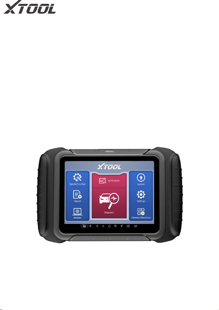
FRONT VIEW OF TABLET
Figure 1-1 Sample of Tablet Front View
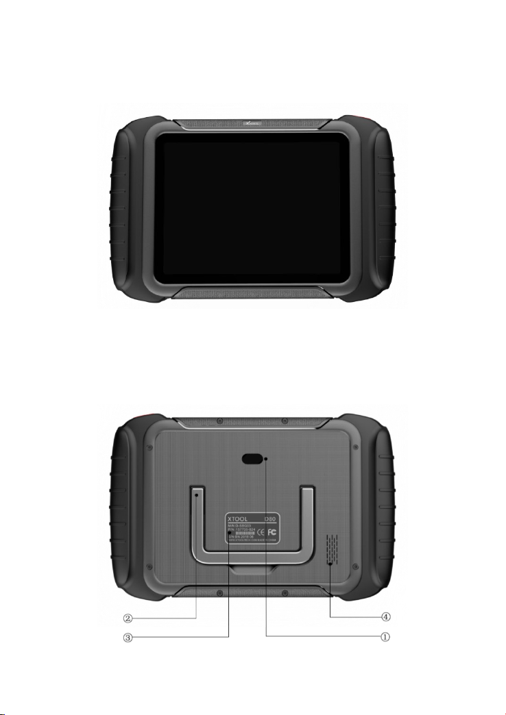
BACK VIEW OF TABLET
3
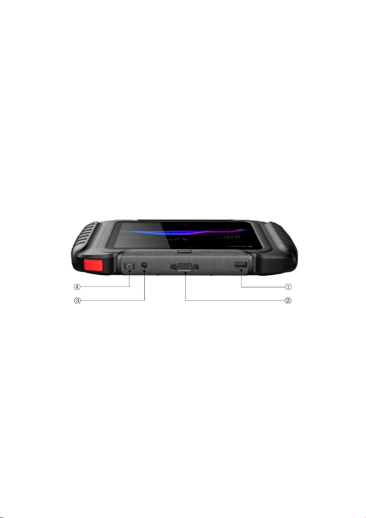
Figure 1-2 Sample of Tablet Back View
① Camera: 8-megapixel camera, for taking pictures.
② Tablet Holder: Used to support the tablet, flexible adjustment of the
tablet height as needed.
③ Nameplate: Display the basic information about the tablet such as
product name and model etc.
④ Loudspeaker: It supports playing external sounds.
The front of the main unit is a touchable display screen, you can use your
fingers to operate on the screen to complete the car diagnosis.
HOST PORTS
Fig 1-3 Sample of Tablet Host Ports
① USB 3.0 port: Data transfer interface for tablet communication and
diagnostics.
② VGA port: A reserved interface can be used for charging.
③ DC charging port: Charging port, connected to the charger can be
charged.
④ Power button: Long press to turn on/off, short press to rest/brighten
the screen.
4
1.2. VCI BOX
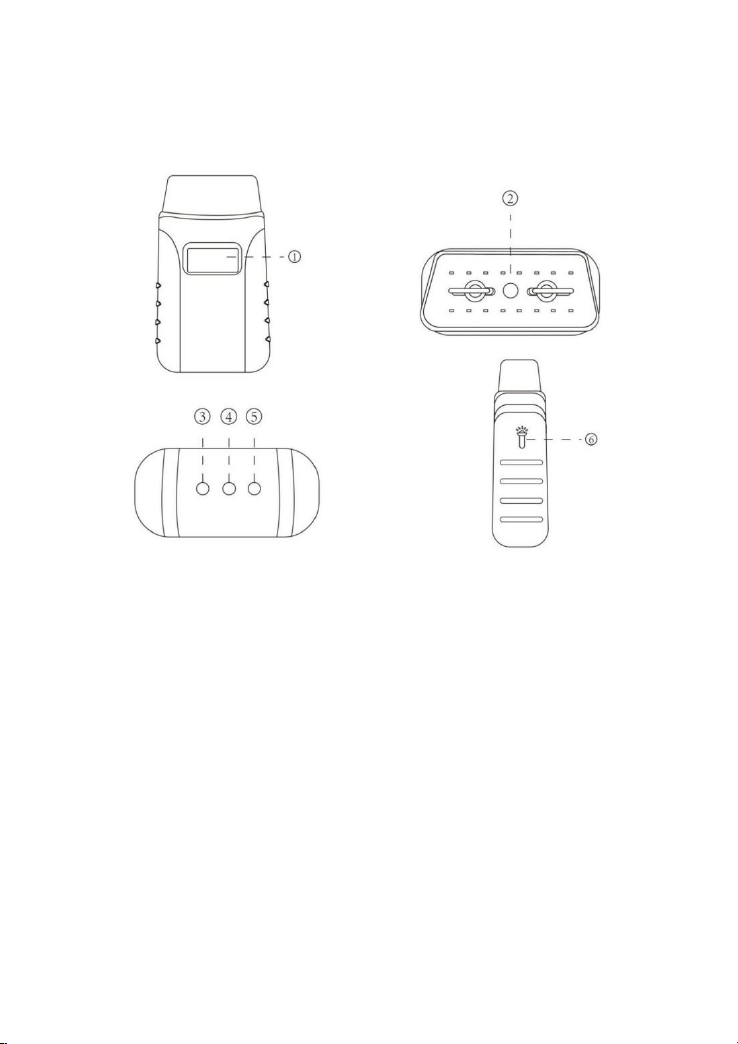
Fig 1-4 Sample of VCI Box
① LCD: Display the battery voltage of the vehicle
② OBD 16 pin connector: Insert the OBD-Ⅱ port on the vehicle
③ Light button: provide lighting function
④ Bluetooth Indicator: It turns blue when Bluetooth is connected
successfully
⑤ Power Indicator: It turns red when power is on
⑥ Vehicle Indicator: The green light flashes when the VCI box
communicates with the vehicle successfully

5
1.3. SPECIFICATIONS
Table 1-1 Specification
Item
Description
OS
Android
Processor
Quad-core processor 1.8GHz
Ram
2G
Rom
64G
Display
8-inch capacitive, 1024×768 resolution
Connectivity
USB
Wi-Fi
Camera
8-megapixel autofocus rear camera with
flash
Sensor
Gravity sensor
Audio Input/ Audio Output
Microphone/ Loudspeaker
Ports
USB3.0
DC charging port
VGA port
Battery
10000mAh 3.7V lithium polymer battery
Input Voltage
12V DC
Operating Temperature
-10~50℃

6
Relative Humidity
< 90%
Dimensions
274.0×175.0×33.8 mm
1.4. PACKING LIST
Table 1-2 Packing List
Category
No.
Name
QTY
Main Units
1
Tablet PC
1
2
VCI Box
1
3
USB 3.0 Cable
1
Adaptor
1
DC12V(AC100~240V) 3A
1
2
US power cable
1
3
EU power cable
1
Accessories
1
Tool kit
1
2
Certificate of Quality
1
3
Packing List
1
4
User Manual
1
5
Carton
1
7
2 GETTING STARTED
2.1. ACTIVATION
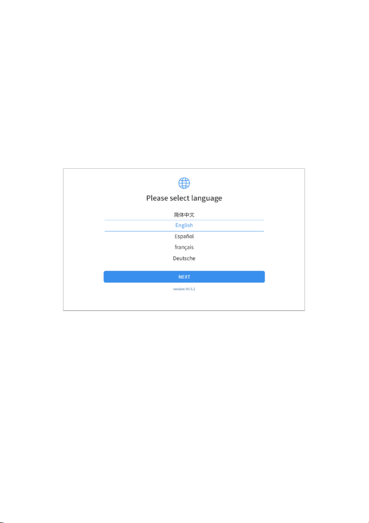
After first-time users press and hold the power button to turn on the system,
the system will automatically enter the guide process and request to select
the language for the operating system.
Figure 2-1 Sample of Selection Languages
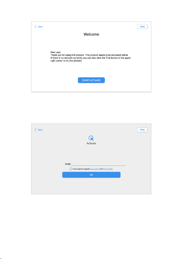
After setting the system language, you will enter the activation page, as
shown in the figure below. You can also click the "Trial" button in the upper
right corner to try it out before activation.
8
Figure 2-2 Sample of Activation (Screen 1)
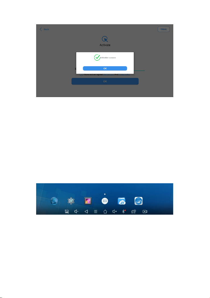
Click Start Activate to enter the activation page, as shown below:
Figure 2-3 Sample of Activation (Screen 2)
A pop-up window showing Activation Success indicates that you have
completed the first boot setup, click OK to enter the diagnostic system and
start using the device.
9
Figure 2-4 Sample of Activation (Screen 3)
2.2. MAIN INTERFACE
OPERATION SYSTEM
As shown in the figure below, this interface is the main page of the operating
system of the device. You can also return to this interface at any time by
clicking 【】on the bottom navigation bar.
Figure 2-5 Sample of OS Main page
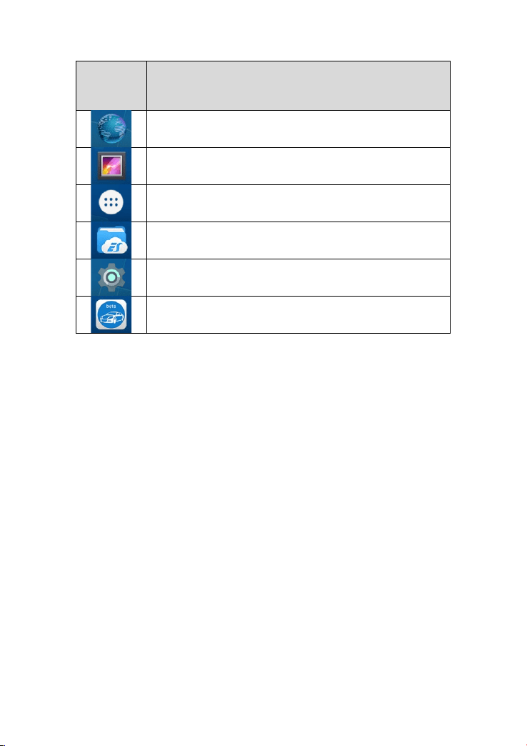
The icons on the right, from top to bottom, are browser, photo album,
application square, file manager, system settings, as shown below:
Table 2-1
10
Items
Descriptions
Browser
Album
Application Square
File Explorer
Settings for Android System
D8 BT Smart Diagnosis System
1) Browser: Click on the browser icon to enter the browser to view the
official website of Xtool or search for other information.
2) Gallery: Click the Gallery icon to enter the album to quickly view the
pictures or screenshots stored in the device. You can select the picture
you need, click the share button on the upper right, and send the picture
to your mobile phone or PC via Bluetooth or USB connection
3) Application Square: You can check all Apps installed here.
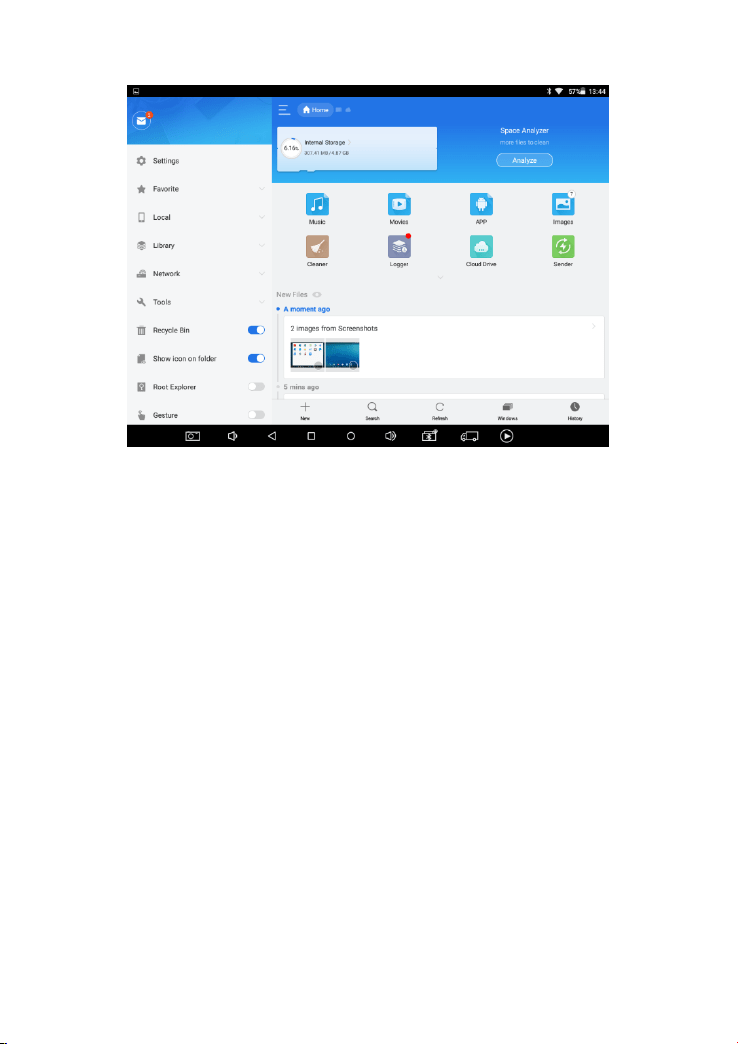
4) ES File Explorer: You can manage APP, music, files, pictures, etc. in
the device in this function, and you can also use Local/Home/Cleaner
to clean up files.
11
Figure 2-6 Sample of ES File Explorer
5) D8 BT Smart Diagnosis System: The App allows you to diagnose
your vehicle and offers a range of specialist maintenance services.
DIAGNOSIS SYSTEM ENTRANCE
Once activated, you will automatically enter the diagnostic system with the
following main screen. Tap on the diagnosis application button on the menu,
the main interface will be shown as below:
12
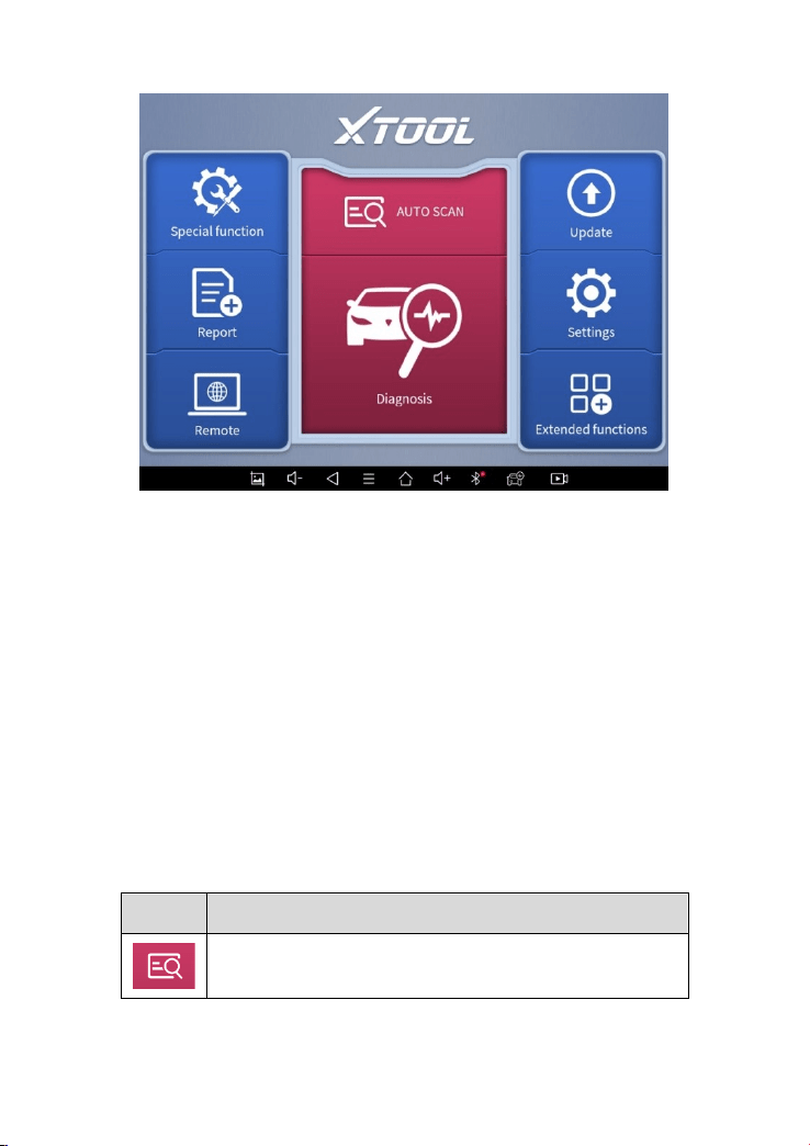
Figure 2-7 Sample of APP Main Page
The main interface is mainly composed of Function Buttons and
Navigation Buttons. The touch screen navigation is menu-driven, and you
can quickly access functions by clicking on the option title and answering the
dialogue window. A detailed description of the menu structure can be found
in the next section Function Buttons.
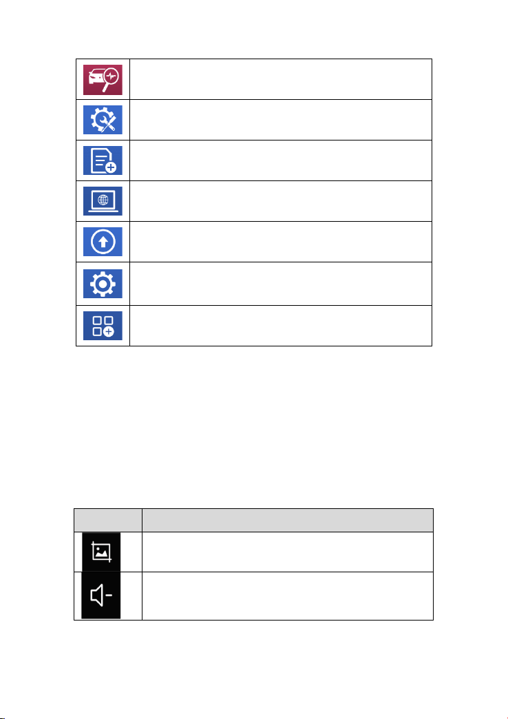
FUNCTION BUTTONS
The following table briefly describes each function button
Table 2-2
Item
Description
Quickly access to the vehicle system to identify the
vehicle VIN code
13
Enter to select a vehicle
Includes special functions for car diagnosis
You can view the vehicle diagnostic report
In case of failure, you can control the diagnostic
equipment remotely
Users can upgrade the upgradeable software with one
click
Users can set the language, unit, Bluetooth, repair shop
information, also can view information about this
software
Users can view extended functions such as Xtool Cloud
here
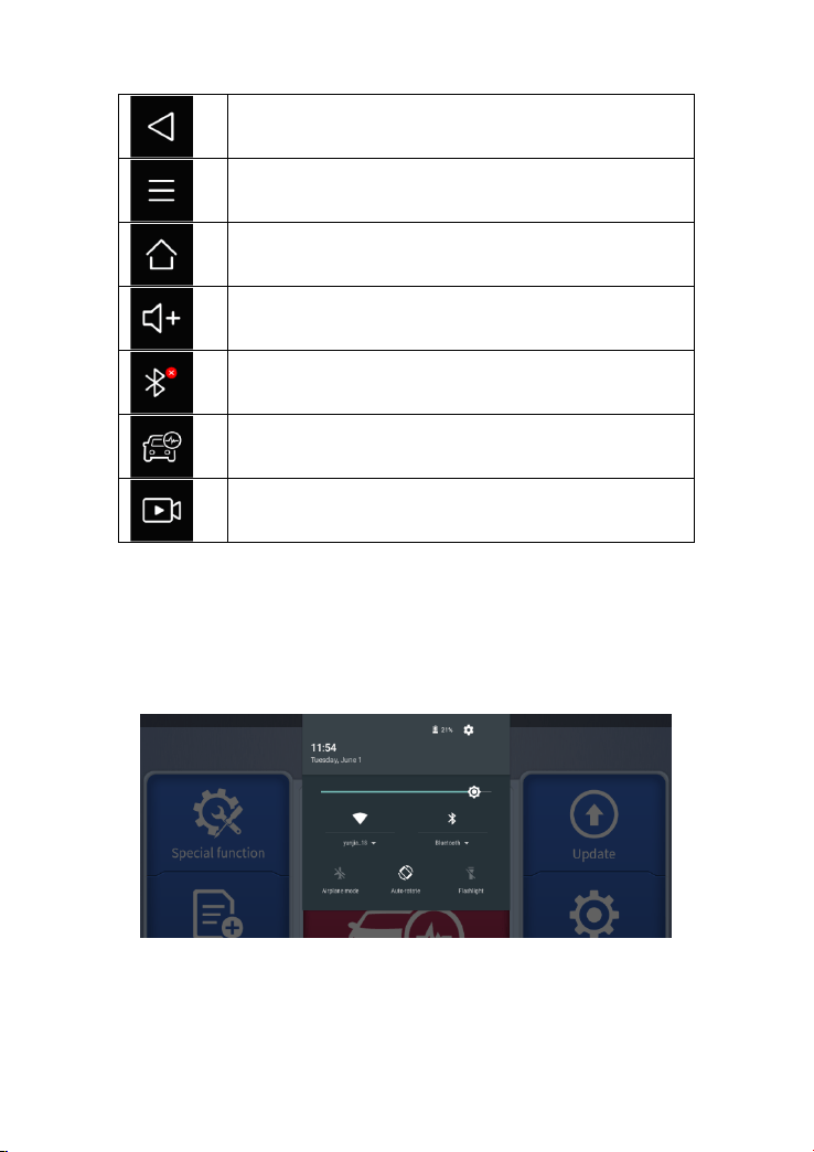
NAVIGATION BUTTONS
Instructions for operating the navigation bar buttons at the bottom of the
screen, as described in the table below:
Table 2-3
Items
Descriptions
Press for screenshot
Decrease volume
14
Back to the previous interface
Shows recently used applications
Back to the main interface of the Android system
Increase volume
Showing the Bluetooth states
Click this button to return to the diagnostic vehicle
interface
Press for screen recording
NOTIFICATION BAR
Slide down to open the notification bar. Users can adjust the brightness of
the screen when they need it, and you can also connect Wi-Fi and so on.
Figure 2-8 Sample of NOTIFICATION BAR
15
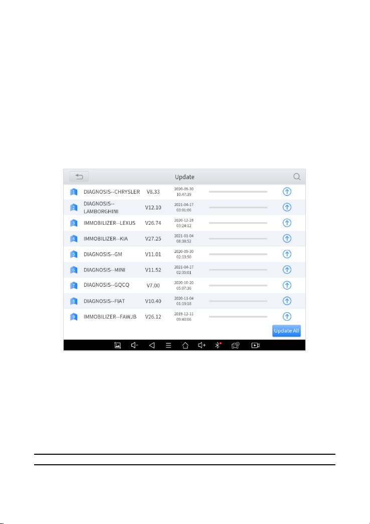
3 UPDATE &DELETE SOFTWARE
3.1. UPDATE SOFTWARE
After activating the device, please update the software in "Update" first. To
access the update application, open the diagnosis application and click
UPDATE, shown as below:
Figure 3-1 Sample of Update List
1. Click the magnifying glass in the upper right corner to search for model
software by keywords
2. Click the up arrow on the right to download the specified package
3. Click UPDATES All at the bottom right to download all packages
NOTE: After activating the device for the first time, please check the
update. Software updates in English and the local languages are
16
generally supported, but to save storage space, we recommend that
you better update in one language
.
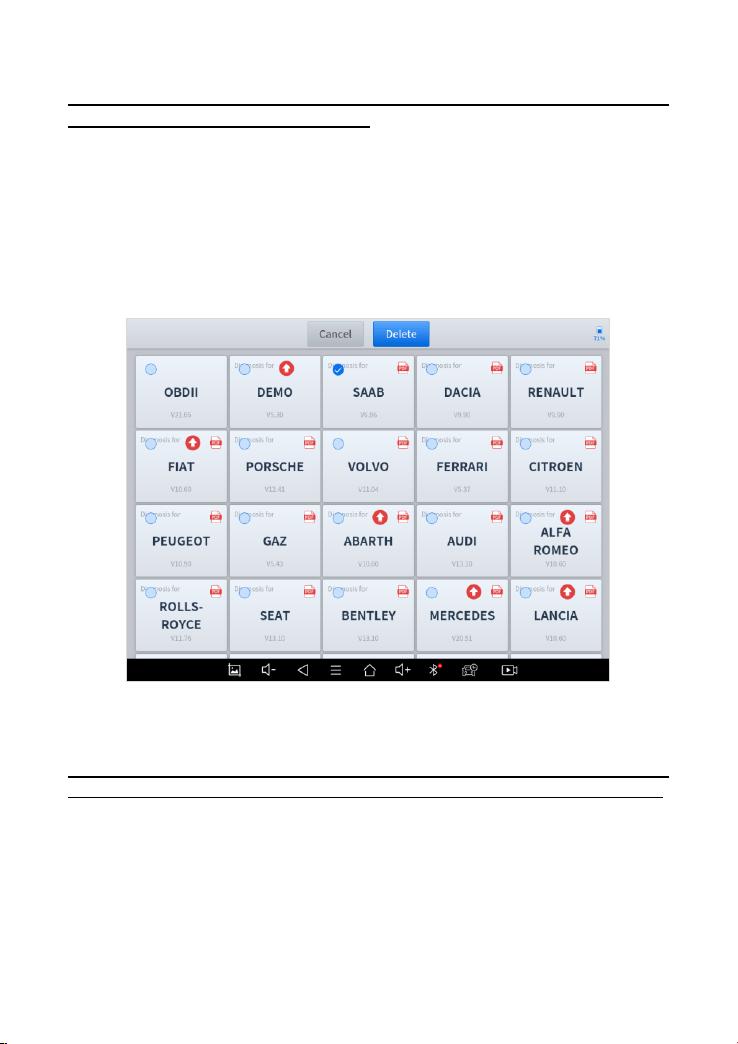
3.2. DELETE SOFTWARE
Long-press the unwanted software until it has been selected, then click the
Delete button shown on the upper part of the screen. And you can select
and delete multiple software at once.
Figure 3-2 Sample of How to Delete Vehicle Software
** When the device prompts that the memory is insufficient, you can
delete the models that are not frequently used to release the memory.

17
4 DIAGNOSIS
The diagnostic application can read ECU information, read and clear DTC
and check living data and freeze frames. The diagnosis application can
access the electronic control unit (ECU) of various vehicle control systems,
including the engine, transmission, anti-lock braking system (ABS), airbag
system (SRS), and perform kinds of actuation tests.
4.1. VEHICLE CONNECTION
The diagnosis operation needs to connect the D8 BT smart diagnosis system
to a vehicle first so that the tablet can establish correct vehicle
communication.
⚫ Please perform the following steps:
1. Start the tablet
2. Plug the VCI box into the OBD port on the vehicle, the red light of the
VCI box indicates that the power is on
3. Connect the tablet to the VCI box via Bluetooth in Settings after 5
seconds, and the blue lights indicate that the connection is successful
4. Turn on the ignition switch and click the diagnostic App to test the
vehicle. When the car interacts with the diagnostic program, the VCI
box flashes green
The connection method is shown in the figure below:
Figure 4-1 Sample of How to Connect Device to Vehicle

18
⚫ Precautions for Diagnosis
1. The battery voltage range on the car: +9~+36V DC;
2. When testing some special functions, the operator must operate according
to the prompts and meet the test conditions. For some models [special
functions], the conditions that need to be met are: engine water temperature
80℃~105℃, turn off headlights and air conditioners, Keep the accelerator
pedal in the released position, etc.;
3. As the electronic control systems of different models are more complicated,
if you encounter situations where it is impossible to test or a large amount of
test data is abnormal, you can search for the ECU of the vehicle and select
the menu through the model on the ECU nameplate;
4. If the vehicle type or electronic control system to be tested is not found in
the D8 BT diagnostic function, please upgrade the vehicle diagnostic
software to the latest version or consult the technical service department;
5. It is forbidden to use wiring harnesses other than Xtool for connection
testing to avoid unnecessary losses;
6. In the communication between the D8 BT Smart Diagnosis System and
the vehicle, it is forbidden to shut down directly. You should cancel the task
before returning to the main interface.
4.2. DIAGNOSIS
After the tablet device is properly connected to the vehicle, you could start
the vehicle diagnosis.
VEHICLE SELECTION
The D8 BT intelligent diagnosis system supports the following 4 ways to
access the vehicle diagnosis system.
19
⚫ AUTO SCAN
⚫ SCAN CODE
⚫ MANUAL ENTER
⚫ SELECT VEHICLE BY AREA
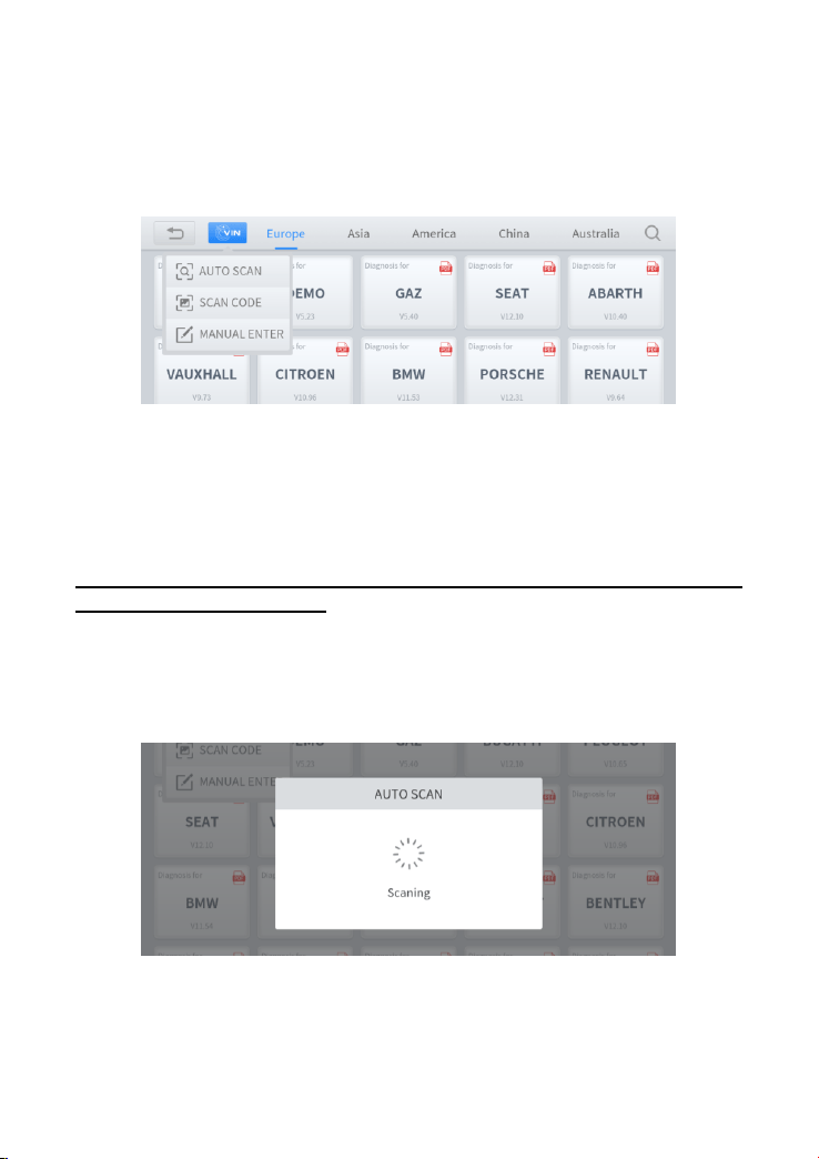
Fig 4-2 Sample of Vin Identification
Click the VIN button in the upper left corner, you can choose to enter the
vehicle diagnosis through the first 2 ways of AUTO SCAN/ MANUAL ENTER.
※
Please make sure that the car and the device are well connected
before using this function.
⚫ AUTO SCAN: It supports automatic reading of vehicle VIN code. You
also can tap on the button “AUTO SCAN” on the diagnosis system
entrance to use this function.
Fig 4-3 Sample of AUTOSCAN
20
※ NOTE: In order to improve the scanning speed of AUTOSCAN, this
function is not compatible with some old car protocols of Nissan,
Toyota and Mercedes-Benz. If your car cannot be recognized by
AUTOSCAN, please try to enter the car menu and use Auto
detection to identify your vehicle model.
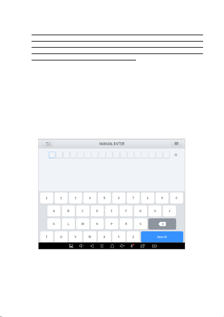
⚫ MANUAL ENTER
It supports manual input of car VIN code. When entering the VIN code
manually, make sure that the 17 characters entered are correct to avoid
reading failure.
After manually entering the VIN code, this page will keep the history,
you can directly click on the records to identify without having to enter
it again.
Fig 4-4 Sample of Manually Inputting Vin
21
※ NOTE: This function keeping the history of manually inputting the
VIN code, you can directly select the history record below to
confirm the vehicle information after the first manually input.
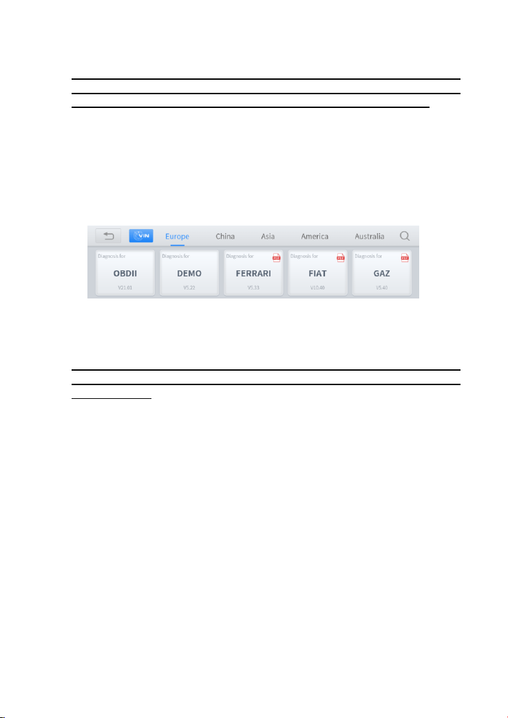
⚫ SELECT VEHICLE BY AREA
In addition to the above 3 methods, you can also choose a car brand
according to the region. You can select the vehicle model that needs to be
diagnosed according to the area, as shown below:
Figure 4-5 Sample of Vehicle Selection by Ares
※ NOTE: If you need to view the list of functions covered by the
model, you can click the PDF icon at the top right of the model
brand button.
OBD- Ⅱ supports reading the related fault codes of PCM; DEMO, a
demonstration program; Click this button to experience and learn the
operation process of the diagnostic function. Some models provide multiple
entry methods in the sub-menu, including:
⚫ Automatic Detection
⚫ Manual Selection
⚫ System Selection
22
Figure 4-6 Sample of Diagnosis Method Selection
Automatic Detection will automatically identify the vehicle's VIN code, and
then read the information of your target diagnostic object.
If you choose "Manual selection", then you can continue to select the
vehicle brand, year, and model of the vehicle in the sub-menu to diagnosis
the vehicle. Enter "System Selection", you can also diagnose the vehicle
according to the system according to your needs after selecting the model.
DIAGNOSTICS FUNCTIONS
The diagnosis functions supported by system, as follows:
⚫ Read ECU Information
⚫ Read/Clear Trouble Code
⚫ Read Live Data
⚫ Freeze Frame
⚫ Actuation Test (Bi-Directional Control)
⚫ Special functions
23
Figure 4-7 Sample of Basic Function
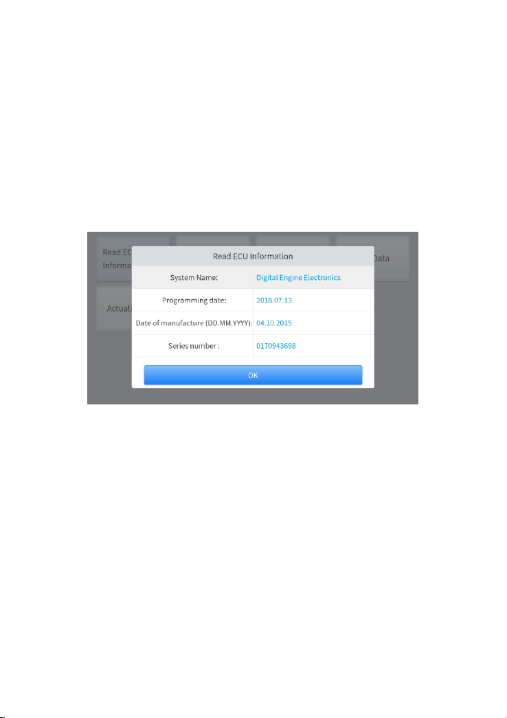
◼ Read ECU Information
This function is to read ECU version information, which is the equivalent of
"System Identification" or "System information in some electronic control
systems, all mean to read ECU related software and hardware versions,
models and production date of diesel engine, part number, etc. It is
convenient for us to make a record in the maintenance process, and it also
makes data feedback and management easier.
Figure 4-8 Sample of ECU Information
◼ Read Trouble Code
Read the trouble codes stored in the ECU, including historical trouble codes,
current trouble codes and pending trouble codes. The trouble code status
will tell you what type of trouble codes are read.
24
Figure 4-9 Sample of Read DTC
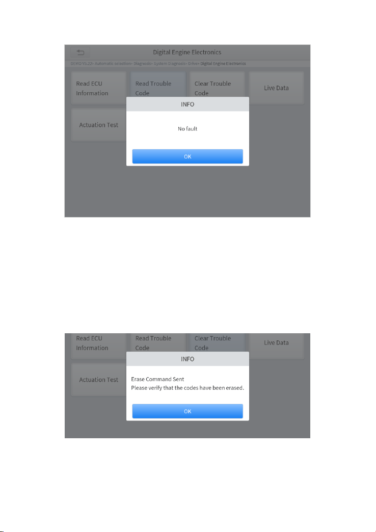
◼ Clear Trouble Code
It allows clearing current and historical trouble codes memory in ECU, under
the premise that all the troubles are eliminated. Historical fault codes and
some current static fault codes can be cleared directly.
Figure 4-10 Sample of Clear DTC
25
However, the trouble codes can’t be erased without eliminating all the
troubles, which will cause the diagnostic tool to always read the trouble code
because the code will always be saved in ECU, and some active fault codes
need to perform some special functions, or remove the car hardware failure
before clearing.
◼ Read Live Data
That is to read the parameters of the running engine, such as oil pressure,
temperature, engine speed, fuel oil temperature, coolant temperature, intake
air temperature, etc. Based on these parameters, we can judge directly
where the problem lies, which helps to narrow the scope of maintenance.
For some vehicles, during their actual operation, the problems such as
performance characteristics offset, sensitivity reduction, can be judged in live
data.
Figure 4-11 Sample of PIDs List
In the process of diagnosis, if the device shows “System is OK” or “No
Trouble Code”, it means there is no related trouble code stored in ECU or
some troubles are not under the control of ECU, most of these troubles are
mechanical system troubles or executive circuit troubles, it is also possible
that signal of the sensor may bias within limits, which can be judged in Live
Data.
26
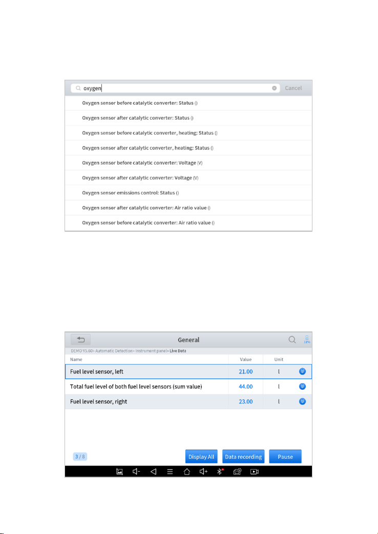
⚫ Click the magnifying glass on the top right, you can search for related
PIDs based on keywords
Figure 4-12 Sample of the PIDs List related by Key Words
⚫ Custom
Support to show the selected PIDs. Click Display All, back to the page which
display all PIDs
27
Figure 4-13 Sample of Custom the PIDs
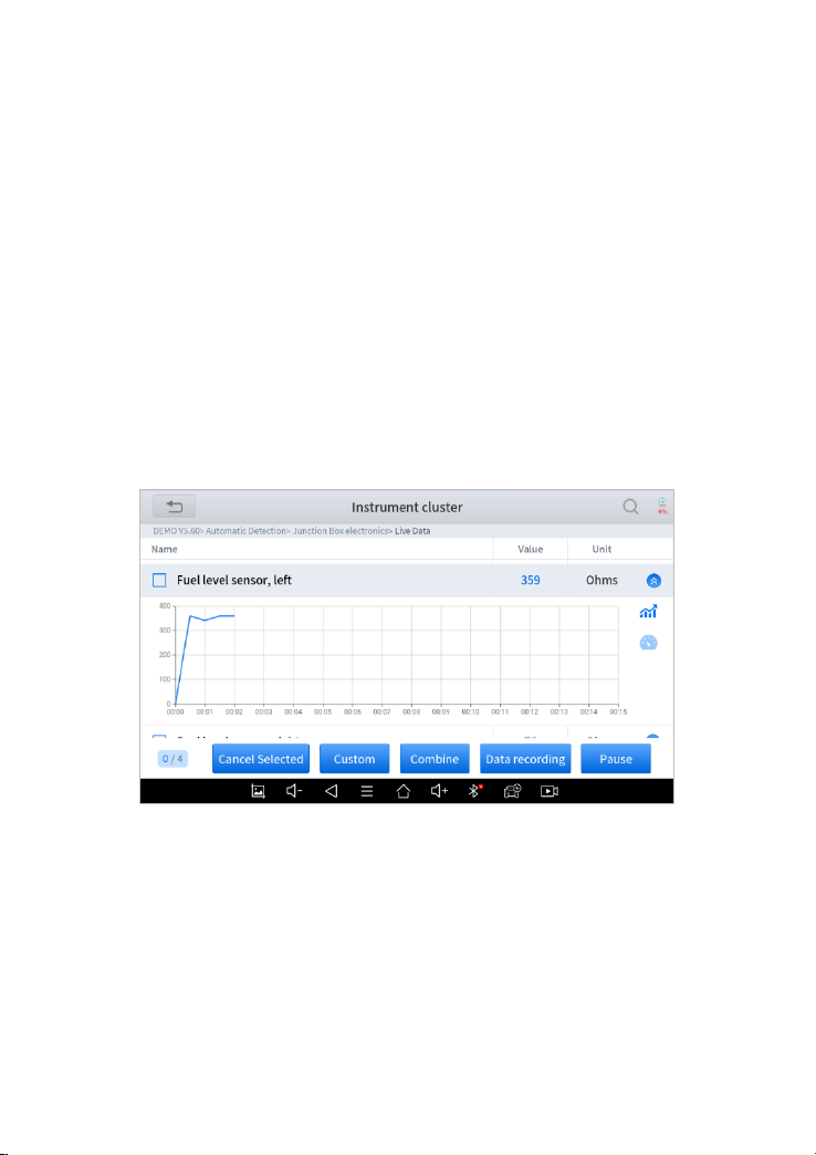
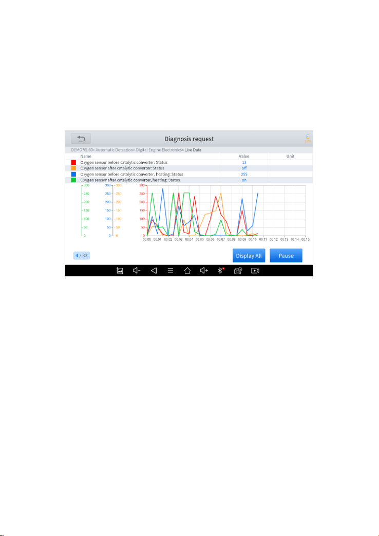
⚫ Combine
Support to select multiple PIDs and click 【Combine】 to make different
graphs into one chart.
Figure 4-14 Sample of the PIDs Combination
⚫ Data recording
Supports recording the current data value in the form of text, you can view
the recorded files in Reports->Data Replay.
⚫ Pause
Click this button to pause the timeline of timeline
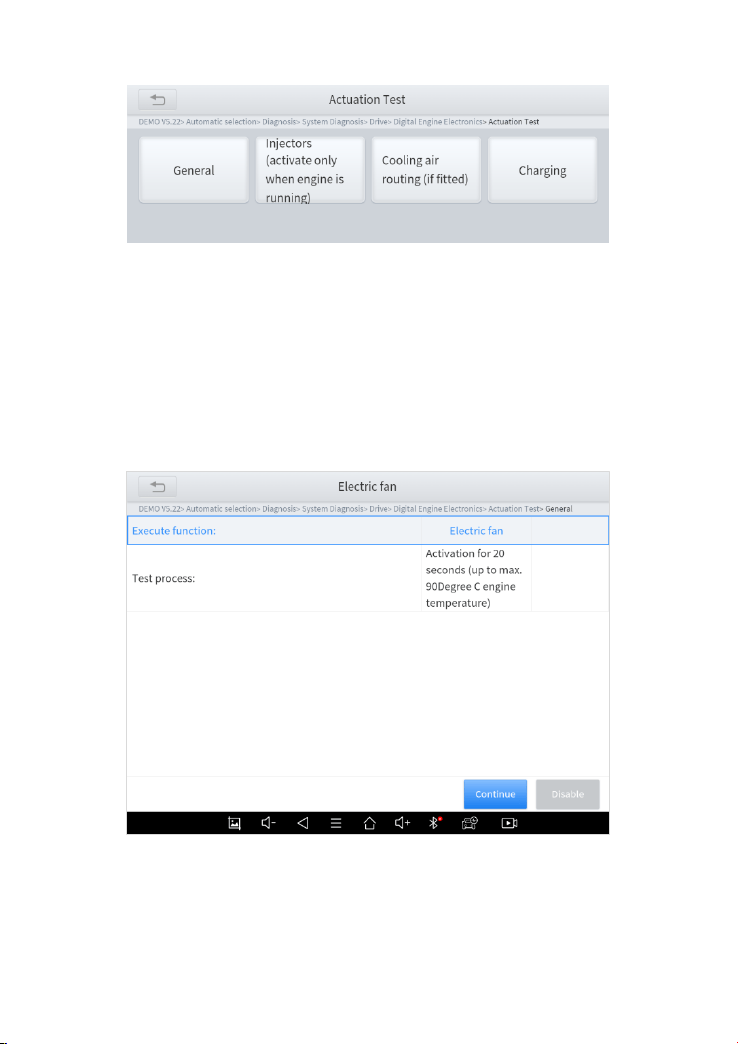
◼ Actuation Test (Bi-Directional Control)
Actuation test, also known as bidirectional control, is a generic term used to
describe sending and receiving information between one device and another.
28
Figure 4-15 Sample of the Actuation Test Menu
The vehicle engineers responsible for designing computer control systems
programmed them so a scan tool could request information or command a
module to perform specific tests and functions. Some manufacturers refer to
bidirectional controls as functional tests, actuator tests, inspection tests,
system tests or the like. Reinitialization and reprogramming also can be
included in the list of bidirectional controls.
Figure 4-16 Sample of the Actuation Test
29
This function allows the device to send information to and receive information
from, vehicle control modules. For example, in the case of OBD II generic
information Mode 1 (which relates to data parameters), the scan tool user
initiates a request for information from the powertrain control module (PCM),
and the PCM responds by sending the information back to the scan tool for
display. Most enhanced scan tools also can actuate relays, injectors and
coils, perform system tests, etc. Users could check the individual part to see
what is working properly by actuation test.
◼ Freeze Frame
When the signal of the sensor is abnormal, the ECU will save the data at that
moment of failure to form a freeze-frame. It is usually used to analyze the
reasons that may lead to car failures.
The living data items supported by vehicles of different brands are not the
same, so the freeze frames displayed when diagnosing vehicles of different
brands may also be different. Some vehicles may not have the option of a
freeze-frame which means that the model does not support this function.
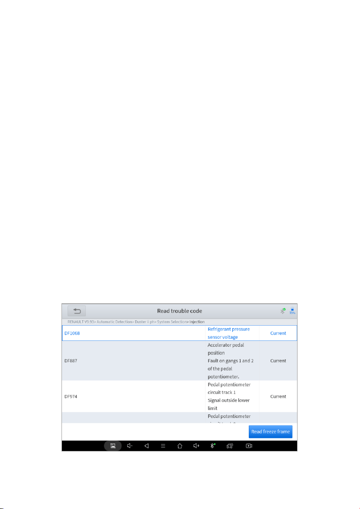
Take Renault Duster ii ph as an example, after selecting the system to enter
the lower freeze frame menu, the device will list all the fault codes under the
system.
30
Figure 4-17 Sample of the Freeze frame for Renault Duster ii ph (Screen 1)
Users can click on a fault code, such as DF1068 to view the freeze frame
recorded by the car when the fault code occurs, including context when the
fault appeared, and current context and additional data.
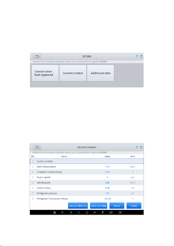
Figure 4-18 Sample of the Freeze frame for Renault Duster ii ph (Screen 2)
Context when fault appeared: record the live data when fault appeared to
help the user to know the vehicle status. *Some vehicles don't support this
function; users will get a prompt when they click the menu.
Current context: Displays the current live data stream associated with the
DTC
31
Figure 4-19 Sample of the Freeze frame for Renault Duster ii ph (Screen 3)
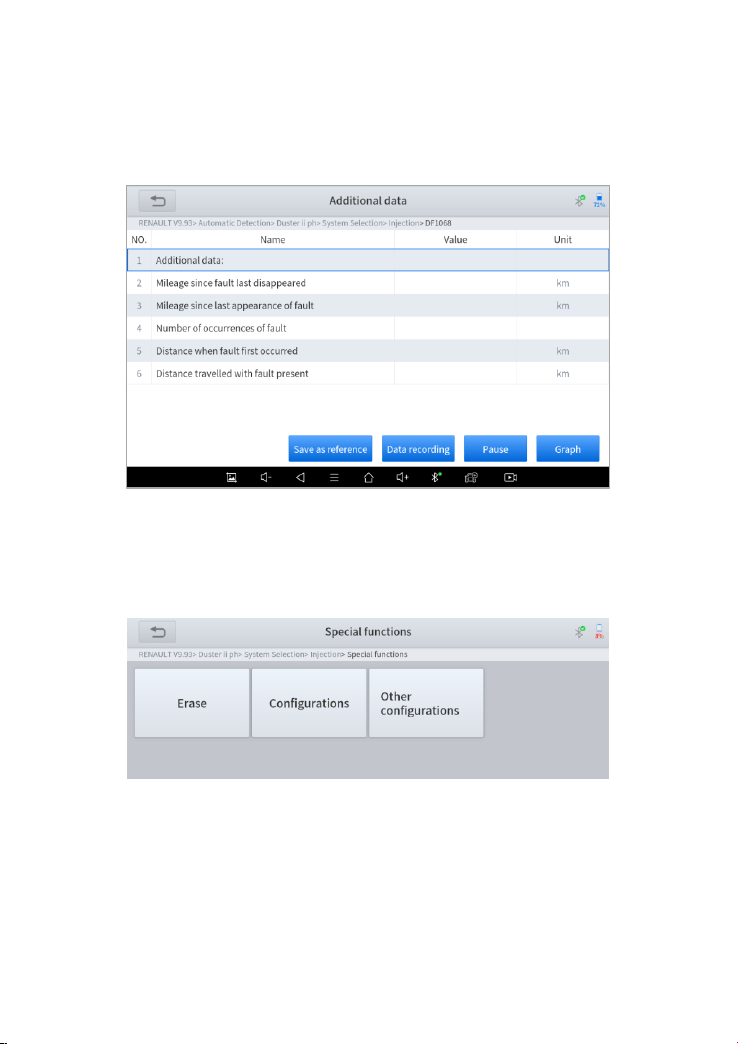
Additional data: record other data related to the fault
Figure 4-20 Sample of the Freeze frame for Renault Duster ii ph (Screen 4)
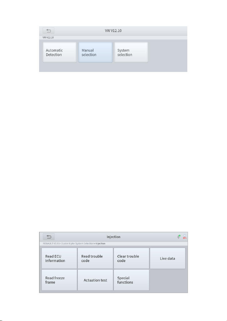
◼ Special functions
Figure 4-21 Sample of the Special Functions for the Injection system of Renault Duster ii ph
Usually, special functions provide various reset or re-learning functions
menus for most vehicle systems. You can easily and quickly solve some
faults through special functions for your car. After some functions are
32
successfully executed, fault codes will be generated, which need to be
cleared manually after the car is running for a little while.
And under each system, you can view the special features supported by that
system. Different models and systems often have different special functions.
Even for the same system of the same model, the years and ECU type may
lead to different special functions supported.
5 SPECIAL FUNCTIONS
The D8 BT Smart Diagnosis System supports the commonly used special
reset functions, allowing you to quickly access your vehicle system for
various scheduled services, maintenance and reset performance,
eliminating the need to reset after resolving common problems. This user
manual lists some of the commonly used special reset services for your
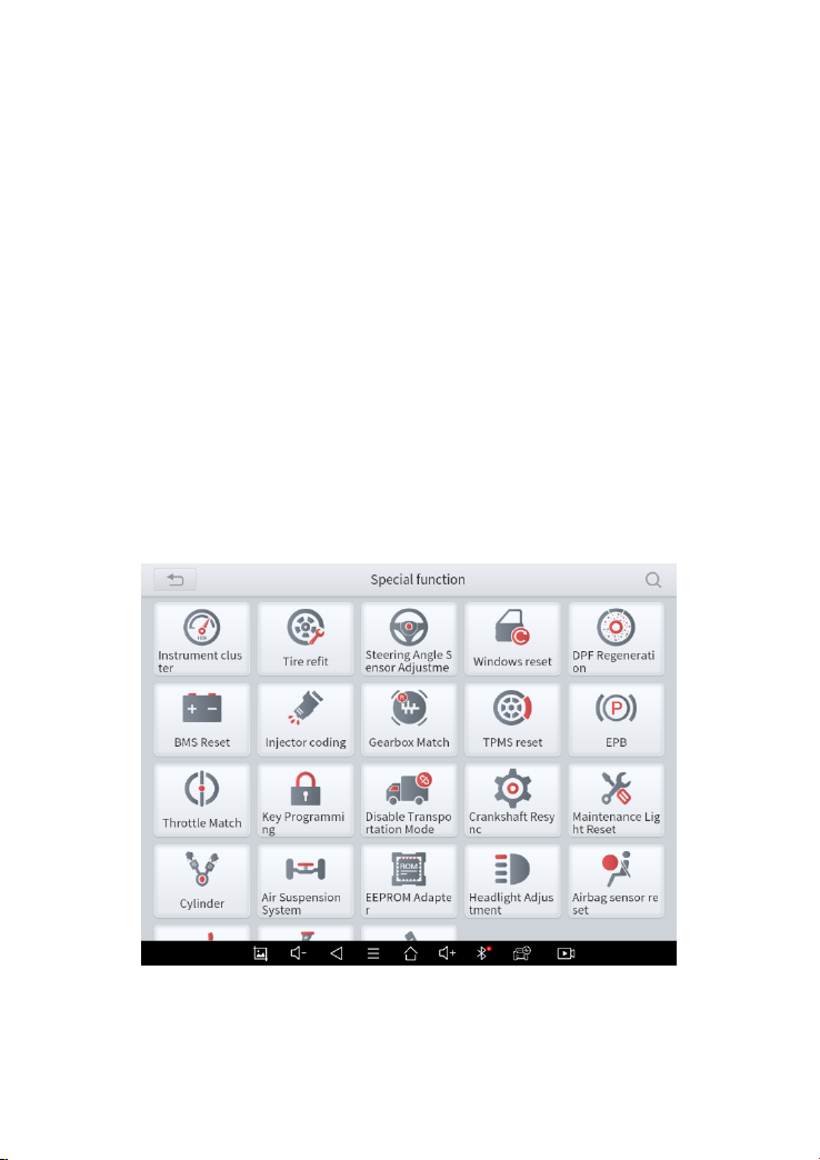
reference. The special functions interface is shown as below:
Figure 5-1 Sample of Special Functions

33
*Note: Due to the limitation of screenshots, the special functions
shown in this picture are not complete. All special functions supported
by D8 BT are subject to the actual special functions displayed on the
device.
5.1 OIL RESET
Reset the Engine Oil Life System, which calculates the optimum oil life
change interval based on the vehicle’s driving conditions and climate. The
oil life reminder must be reset each time the oil is changed so that the system
can calculate when the next oil change is required.
This function can be performed in the following cases:
1. If the service lamp is on, you must provide service for the car. After
service, you need to reset the driving mileage or driving time so that the
service lamp turns off and the system enables the new service cycle.
2. After changing engine oil or electric appliances that monitor oil life, you
need to reset the service lamp.
The operation guidelines of the Oil Reset function are shown as below:
1. Enter the Oil Reset menu and choose relevant models according to the
vehicle being tested.
2. Follow the instructions displayed and press OK after completing the
instructions shown.
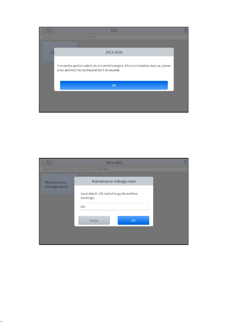
34
Figure 5-2 Sample of oil reset function (screen 1)
3. Enter Maintenance mileage reset menu.
4. Input reasonable value of mileage and press OK.
Figure 5-3 Sample of oil reset function (screen 2)
5. Message of ‘Reset success’ displayed when Oil Reset function has
successfully performed.

35
5.2 EPB
Electronic Parking Brake (EPB) System reset is a popular special function.
You can use this function to reset the electronic parking brake system and
brake pads, which also supports the brake pad replacement (retraction,
release of the brake pump), G-sensor, and body angle calibration. This
function has multiple uses and can safely and effectively maintain the
electronic brake system. These applications include deactivating and
activating brake control systems, assisting in controlling brake fluid, opening
and closing brake pads, setting brakes after replacing brake discs or brake
pads, etc.
1. If the brake pad wears the brake pad sense line, the brake pad sense
line will send a signal to the onboard tablet asking for replacing the
brake pad. After replacing the brake pad, you must reset the brake pad.
Otherwise, the car alarms.
2. Reset must be performed in the following cases:
⚫ The brake pad and brake pad wear sensor are replaced.
⚫ The brake pad indicator lamp is on.
⚫ The brake pad sensor circuit is short, which is recovered.
⚫ The servo motor is replaced.
The operation guidelines of the EPB function are shown as below:
1. Enter the EPB menu and choose relevant models according to the
vehicle being tested.
2. Follow the instructions displayed and press YES after completing the
instructions shown.
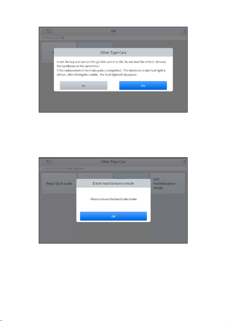
36
Figure 5-4 Sample of EPB function (screen 1)
3. Enter the Enter maintenance mode menu and release the handbrake
brake. And press OK after completing the instructions shown.
Figure 5-5 Sample of EPB function (screen 2)
4. Wait until the message of ‘Successful operation’ popes up. And press
OK to exit the menu.
5. Enter the Exit maintenance mode menu and wait until the message
of ‘‘Successful operation’ popes up.

37
5.3 SAS
Steering Angle Sensors (SAS) System Calibration permanently stores the
current steering wheel position as the straight-ahead position in the SAS
EEPROM. Therefore, the front wheels and the steering wheel must be set
exactly to the straight-ahead position before calibration. In addition, the VIN
is also read from the instrument cluster and stored permanently in the SAS
EEPROM. On successful completion of calibration, the SAS fault codes will
be automatically cleared.
To reset the steering angle, you need to first find the relative zero point
position for the car to drive in a straight line. Taking this position as a
reference, the ECU can calculate the accurate angle for left and right
steering.
After replacing the steering angle position sensor, replacing steering
mechanical parts (such as steering gearbox, steering column, end tie rod,
steering knuckle), performing four-wheel alignment, or recovering the car
body, you must reset the steering angle.
The operation guidelines of the SAS function are shown as below:
1. Enter the SAS menu and choose relevant models according to the
vehicle being tested.
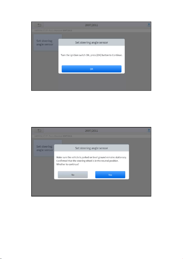
2. Enter the Set steering angle sensor menu and follow the instructions
displayed.
38
Figure 5-6 Sample of SAS function (screen 1)
3. Wait until the following instruction is displayed and press Yes after
completing the instructions shown.
Figure 5-7 Sample of SAS function (screen 2)
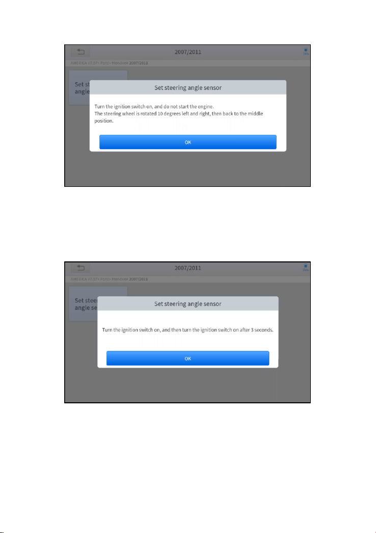
4. Follow the instructions displayed and press OK after completing the
instructions shown.
39
Figure 5-8 Sample of SAS function (screen 3)
5. Wait until the following instruction is displayed and press OK after
completing the instructions shown.
Figure 5-9 Sample of SAS function (screen 4)
6. Message of ‘Function execution is completed’ displayed when SAS
function has successfully performed.

40
5.4 DPF
The Diesel Particle Filter (DPF) function manages DPF regeneration, DPF
component replacement teach-in, and DPF teach-in after replacing the
engine control module (ECM).
The ECM monitors driving style and selects a suitable time to employ
regeneration. Vehicles driven a lot at idling speed and low load will attempt
to regenerate earlier than vehicles driven more with higher load and speed.
For regeneration to take place, a prolonged high exhaust temperature must
be obtained.
In the event of the car being driven in such ways that regeneration is not
possible, i.e., frequent short journeys, a diagnostic trouble code will
eventually be registered in addition to the DPF light and “Check Engine”
indicators displaying. A service regeneration can be requested in the
workshop using the diagnostic tool.
DPF regeneration is used to clear PM (Particulate Matter) from the DPF filter
through continuous combustion oxidation mode (such as high-temperature
heating combustion, fuel additive or catalyst reduce PM ignition combustion)
to stabilize the filter performance.
DPF regeneration may be performed in the following cases:
⚫ The exhaust back pressure sensor is replaced.
⚫ The PM trap is removed or replaced.
⚫ The fuel additive nozzle is removed or replaced.
⚫ The catalytic oxidizer is removed or replaced.
⚫ The DPF regeneration MIL is on and maintenance is performed.
⚫ The DPF regeneration control module is replaced.
The operation guidelines of the DPF function are shown as below:
1. Enter the DPF menu and choose relevant models according to the
vehicle being tested.
2. Enter the DPF regeneration menu.
41
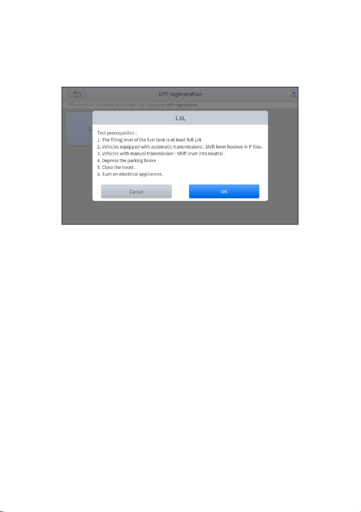
3. Read carefully and complete the requisites listed before performing
the DPF regeneration function. And press OK after completing the
instructions shown.
Figure 5-10 Sample of DPF function (screen 1)
4. Read the fuel tank level and make sure that it fulfills the requirement
displayed.
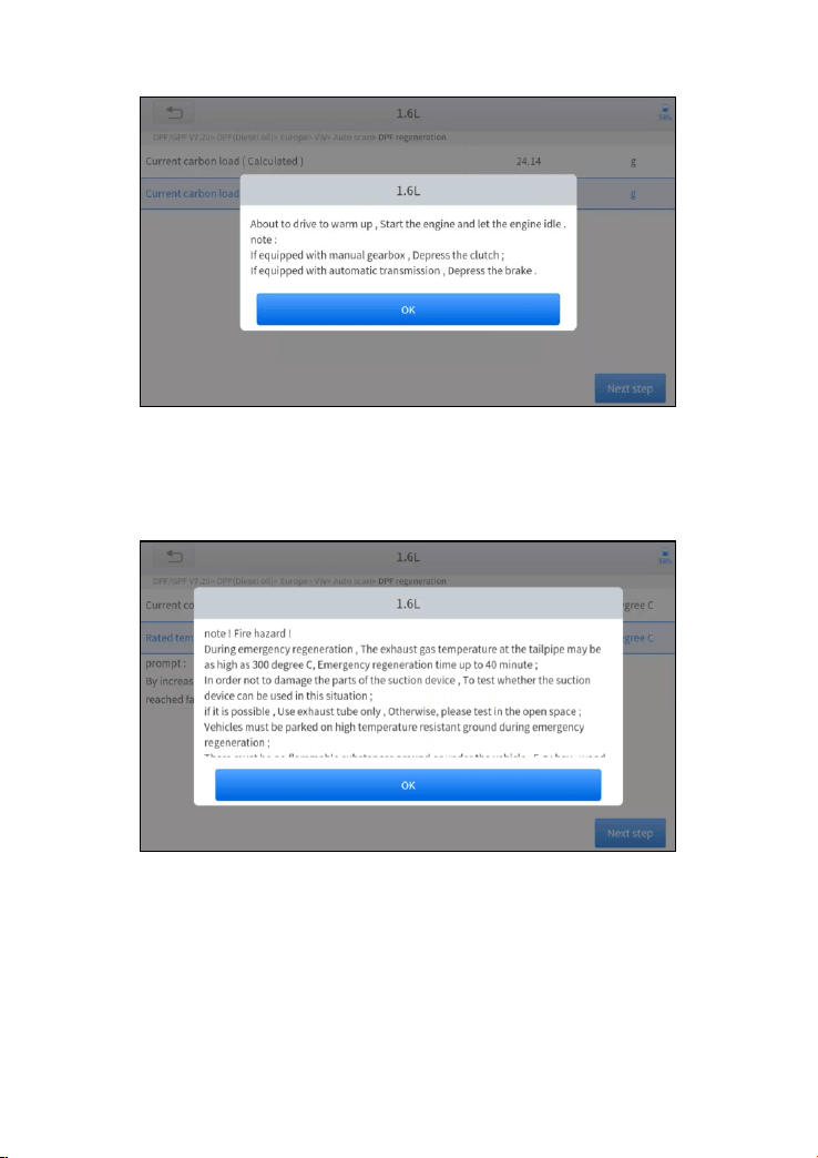
5. Read the carbon deposit load.
6. Choose the drive to warm up and follow the instructions listed below.
And press OK after completing the instructions shown.
42
Figure 5-11 Sample of DPF function (screen 2)
7. Read the note carefully and follow the instructions shown on the screen.
And press OK after completing the instructions shown.
Figure 5-12 Sample of DPF function (screen 3)
8. Follow the instructions displayed and press OK after completing the
instructions shown. Please pay attention to the Note.
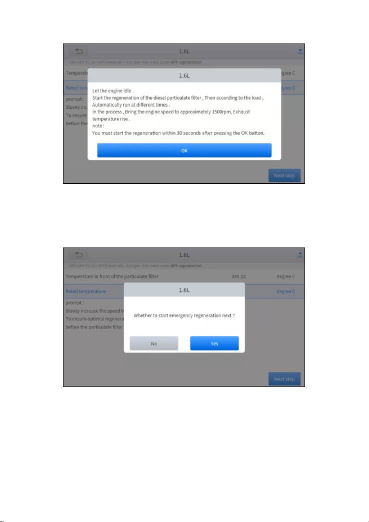
43
Figure 5-13 Sample of DPF function (screen 4)
9. Press the OK button to start the regeneration.
Figure 5-14 Sample of DPF function (screen 5)
10. Wait for the value of carbon deposit to decrease until a message of
‘Emergency regeneration has been completed’ popes up, this process
may take up to 40 minutes.
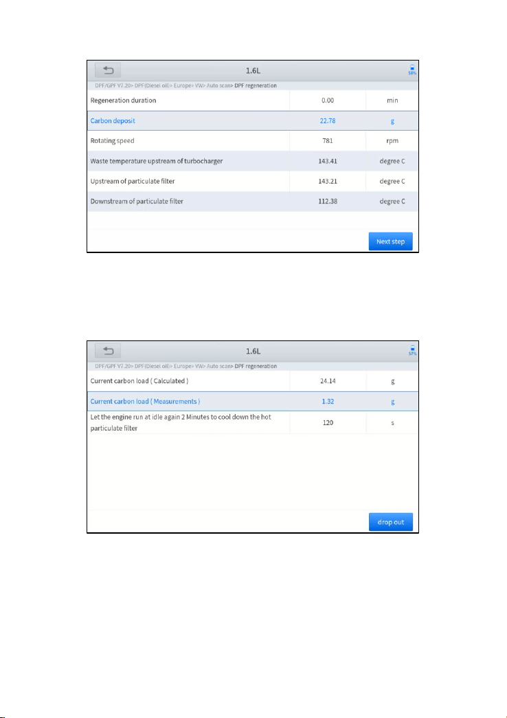
44
Figure 5-15 Sample of DPF function (screen 5)
11. Wait for 2 minutes to let the particulate filter cool down.
Figure 5-16 Sample of DPF function (screen 6)
12. Press drop out to exit the DPF function.

45
5.5 BMS RESET
The Battery Management System (BMS) allows the scan tool to evaluate the
battery charge state, monitor the close-circuit current, register the battery
replacement, and activate the rest state of the vehicle.
This function enables you to perform a resetting operation on the monitoring
unit of the vehicle battery, in which the original low battery fault information
will be cleared and battery matching will be done.
Battery matching must be performed in the following cases:
⚫ The main battery is replaced. Battery matching must be performed to
clear original low battery information and prevent the related control
module from detecting false information. If the related control module
detects false information, it will invalidate some electric auxiliary
functions, such as automatic start & stop function, sunroof without one-
key trigger function, power window without automatic function.
⚫ Battery matching is performed to re-match the control module and
motoring sensor to detect battery power usage more accurately, which
can avoid an error message displayed on the instrument cluster.
The operation guidelines of the BMS Reset function are shown as
below:
1. Enter the BMS Reset menu and choose relevant models according to
the vehicle being tested.
2. Turn on the ignition switch.
3. Press OK to continue the BMS function.
4. Enter battery capacity (within the given range) and press OK after the
input.
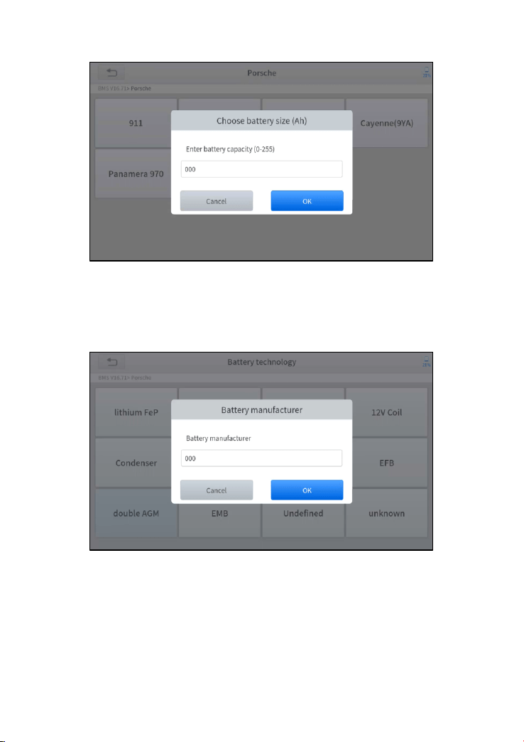
46
Figure 5-17 Sample of BMS function (screen 1)
5. Enter the battery manufacturer and press OK after the input.
Figure 5-18 Sample of BMS function (screen 2)
6. Enter the 10-digit battery serial number and press OK after the input.
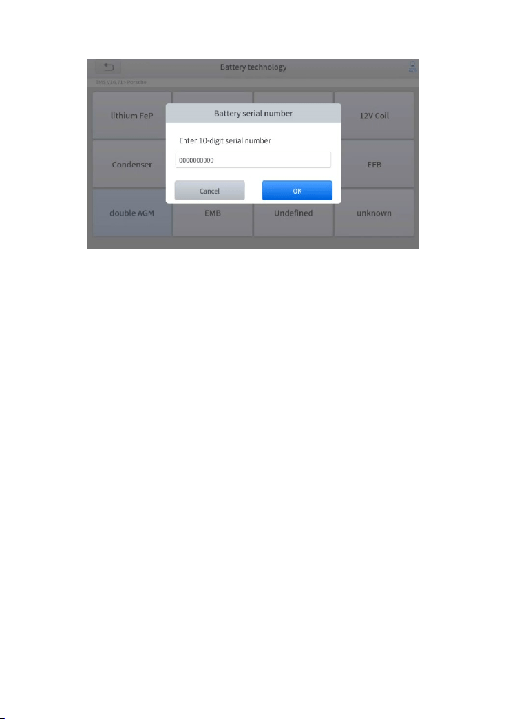
47
Figure 5-19 Sample of BMS function (screen 3)
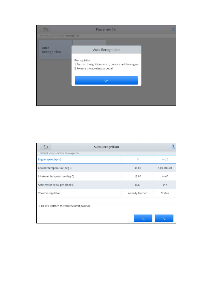
5.6 THROTTLE
Throttle Position Sensor (TPS) Match, this function enables you to make
initial settings to throttle actuators and returns the “learned” values stored on
ECU to the default state. Doing so can accurately control the actions of
regulating throttle (or idle engine) to adjust the amount of air intake.
The operation guidelines of the Throttle function are shown as below:
1. Enter the Throttle menu and choose relevant models according to the
vehicle being tested.
2. Enter the Auto Recognition menu and turn on the ignition switch.
3. Read carefully and complete the requisites listed before performing
the throttle regeneration function. And press OK after completing the
instructions shown.
48
Figure 5-20 Sample of throttle function (screen 1)
4. Wait until all the parameters are read and displayed.
Figure 5-21 Sample of throttle function (screen 2)
5. Press the F2 button and wait until a message of ‘Match successfully’
pops up.

49
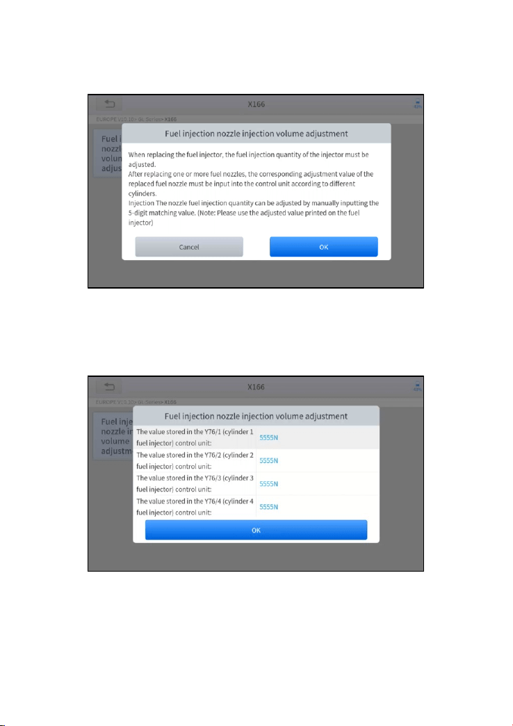
5.7 INJECTOR CODING
This function can write the identification code of the fuel injector into the ECU
so that the ECU can recognize and work normally. Write actual injector code
or rewrite code in the ECU to the injector code of the corresponding cylinder
for controlling accurately and correcting cylinder injection quantity.
After the ECU or injector is replaced, the injector code of each cylinder must
be confirmed or re-coded so that the cylinder can better identify injectors to
accurately control fuel injection.
In general cases, there is no need to do the coding matching function
after cleaning.
The identification of the fuel injector includes its working accuracy
value and type value. When replacing it, you need to find the
corresponding model for replacement.
At present, mainstream cars support injector coding functions.
The operation guidelines of the Injector Coding function are shown as
below:
1. Enter the Injector coding menu and choose relevant chassis models
according to the vehicle being tested.
2. Enter the Fuel injection nozzle injection volume adjustment menu.
50
3. Read the note displayed carefully and press OK after the reading.
Figure 5-22 Sample of injector coding function (screen 1)
4. Read and confirm the value stored in the cylinders.
Figure 5-23 Sample of injector coding function (screen 2)
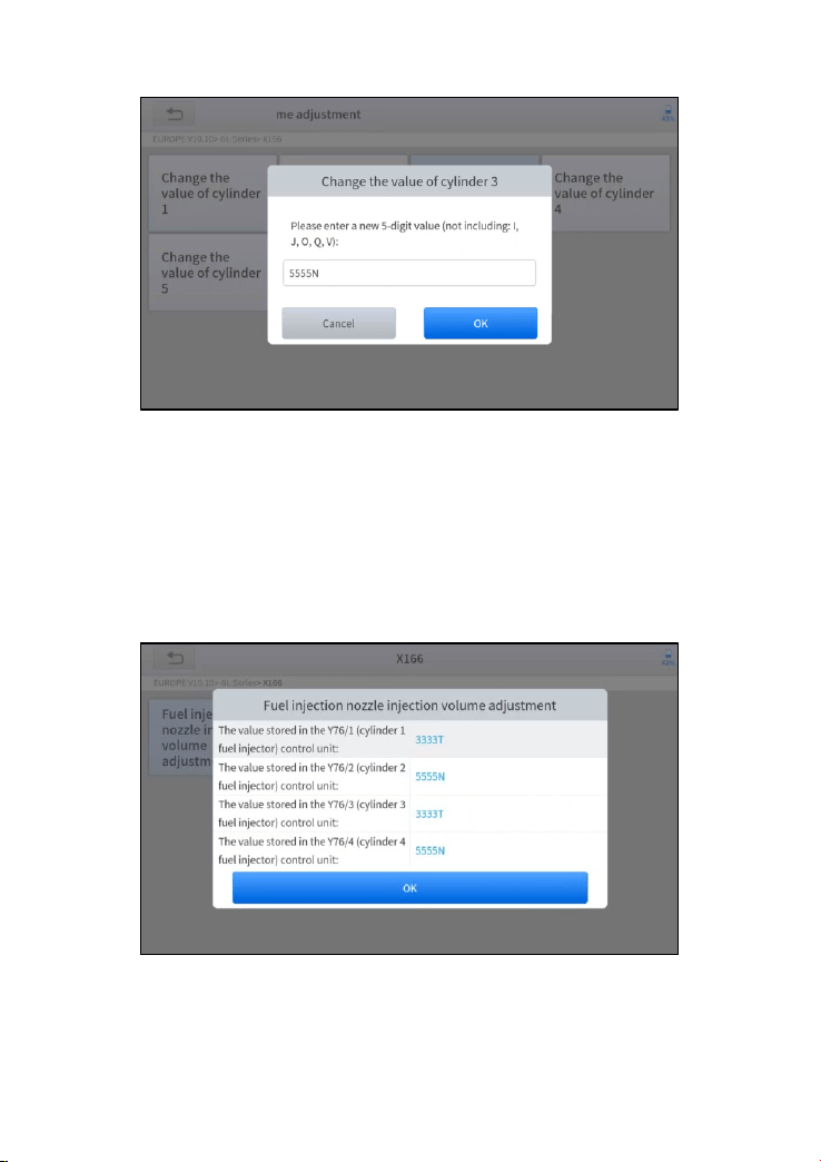
5. Enter the Change the value of cylinder menu of the replaced
injector(s), enter the new 5-digit value, and then press OK.
51
Figure 5-24 Sample of injector coding function (screen 3)
6. Wait until the message ‘Write successfully’ pops up.
7. Turn off the ignition switch.
8. Wait until the message asked you to turn on the ignition switch.
9. Re-enter the Fuel injection nozzle injection volume adjustment
menu to check whether the new value(s) are shown.
Figure 5-25 Sample of injector coding function (screen 4)
52
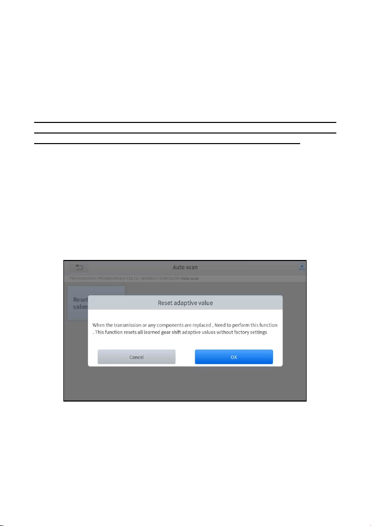
5.8 GEARBOX MATCH
After changing the gearbox or changing the gearbox ECU, you need to use
the gearbox matching function to re-match the engine and the gearbox.
Before resetting the gearbox, please check the gearbox control unit
to ensure that there is no fault code. If there is a fault code, the gearbox
memory function cannot be reset. Please road test after reset.
The operation guidelines of the Gearbox Matching function are shown as
below:
1. Enter the Gearbox matching menu and choose relevant models
according to the vehicle being tested.
2. Enter the Reset adaptive value menu.
3. Turn on the ignition without starting the engine.
4. Read the note and press OK to continue the Gearbox Matching function.
Figure 5-26 Sample of gearbox matching function (screen 1)
5. Wait until the message ‘Successful operation’ popes up.

53
5.9 GEAR LEARNING
The crankshaft position sensor learns crankshaft tooth machining tolerance
and saves to the tablet to more accurately diagnose engine misfires. If gear
learning is not performed for a car equipped with a Delphi engine, the MIL
turns on after the engine is started. The diagnostic device detects the DTC
P1336 'Gear not learned'. In this case, you must use the diagnostic device
to perform gear learning for the car. After gear learning is successful, the MIL
turns off. This function can complete the self-learning of the gearbox and
improve the quality of shifting.
After the engine ECU, crankshaft position sensor, or crankshaft flywheel is
replaced, or the DTC 'gear not learned' is present, gear learning must be
performed.
The operation guidelines of the Gear learning function are shown as
below:
1. Enter the Gear learning menu and choose relevant models according
to the vehicle being tested.
2. Turn on the ignition switch to start the vehicle.
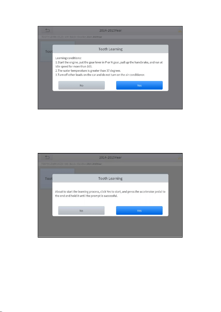
3. Enter the Tooth Learning menu.
Read carefully and complete the requisites listed before performing the gear
learning function. And press OK after completing the instructions shown
54
Figure 5-27 Sample of gear learning function (screen 1)
4. Read the instructions displayed and press Yes to start the learning
process.
Figure 5-28 Sample of gear learning function (screen 2)
4. Press the accelerator pedal down and hold it until a message of ‘The
learning is successful, please release the accelerator pedal.’ pops up.
5. Release the accelerator pedal and press OK to exit the gear learning
function.
55
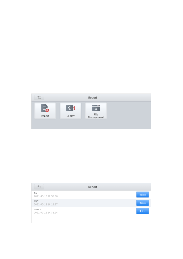
6 REPORT
Diagnostic Report is used for viewing and printing the saved files, such as
Live Data, Trouble codes or pictures generated in the process of diagnosis,
users also can view a record of which cars have been previously tested. It
includes 3 parts:
⚫ Report
⚫ Replay
⚫ File Management
Figure 6-1 Sample of Report
6.1. REPORT
This feature provides a history of diagnostic reports, where you can view and
delete the vehicle's diagnostic reports according to your needs.
Figure 6-2 Sample of Report List
56
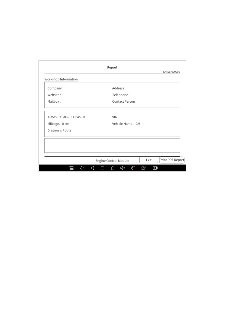
When you open the report, located in the header of the table is the studio
information you filled in advance in the system setup, then the information of
the vehicle, including the diagnosis date and time, VIN, vehicle brand,
diagnosis path, etc., as shown as below:
Figure 6-3 Sample of Report
◼ Print PDF Report
As you can see, you also could click " Print PDF Report " at the bottom right
corner to output the pdf report. If you need to close the report, you could tap
on the button “Exit”.
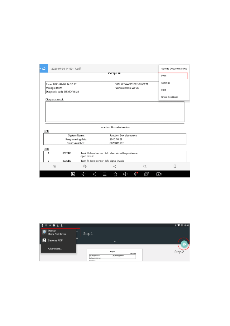
Please follow the below steps to print your report▼
Step 1: Install an APP that can drive your target printer. Add the printer and
input the IP address of the printer in the APP, or you can contact your dealer
for help.
57
Step 2: Back to the Android main menu, go to Settings -> Printing-> Turn
printer on.
Step 3: Report-> Choose report-> Print PDF Report-> Print
Figure 6-4 Sample of How to Print Report, Screen 1
Step 4: Click the top-left corner of the screen and choose the printer you
added before. Then click the button on the right to print.
Figure 6-5 Sample of Report, Screen 2

58
6.2. REPLAY
This function allows you to replay the living data recorded during the
diagnosis process.
Figure 6-6 Sample of Data Playback, Screen 1
Before replaying the living data, please make sure you click on the "Save to
Reference" button during the diagnosis
Figure 6-7 Sample of Data Playback, Screen 2

59
6.3. FILE MANAGER
This function allows you to check and delete files on the device. Please use
this function under the guidance of professionals. Ordinary users are not
recommended to use it by themselves!
Figure 6-8 Sample of File Manager
60
7 SETTINGS
Click the Settings button on main page to adjust the default settings and view
information about the D8 BT Smart Diagnosis System. There are seven
options available in the system settings:
⚫ Language
⚫ Units
⚫ My Workshop Info
⚫ VCI Info
⚫ About
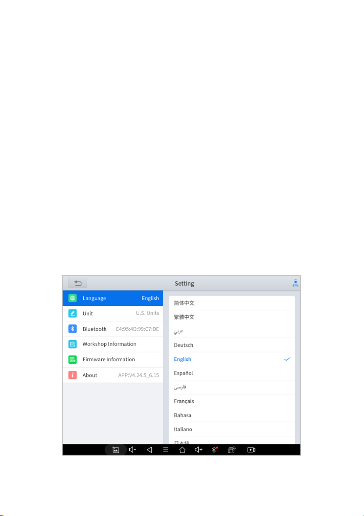
7.1. LANGUAGE
The languages supported by this device are listed in Settings. In areas
outside the English area, the default language is English and the local official
language.

61
Figure 7-2 Sample of Language Selection
Users can switch between English and local official languages on the device
by themselves. If you need to switch other languages, please contact the
dealer to unbind the current language configuration and rebind it to the
language configuration you need to switch. After the configuration is
successfully changed, you can switch the target language.
NOTE: The types and quantities of languages supported are subject to
the actual language types displayed on the device
⚫ Please follow the steps below to switch languages
Step1: Contact your dealer and leave a message about the language you
need and the S/N of your device
Step2: Settings->Language->Choose language
Step3: OS Settings->Language & input->Choose Language
Step4: Back to Upgrade
NOTE: Please be sure to download the model software again after
switching the language, otherwise the diagnosis menu will be blank
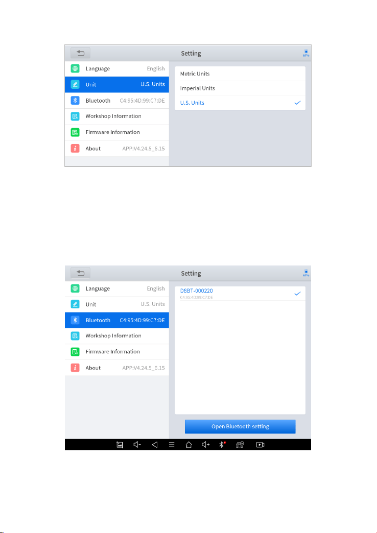
7.2. UNITS
You can switch the unit used by the system. D8 BT Smart Diagnosis System
provides you with metric and imperial units.
You can directly click on the unit when you need it, after the switch is
successful, a blue checkmark will be shown behind the unit’s name.
62
Figure 7-3 Sample of Units Selection
7.3. BLUETOOTH
Check your VCI box bluetooth name here and pair it
Figure 7-4 Sample of Bluetooth Selection
63
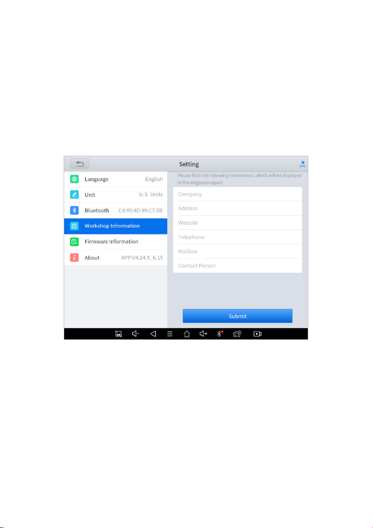
7.4. MY WORKSHOP INFO
Click on My Workshop Information, you can input your workshop
information here. As shown in the figure below, you just need to fill in the
valid information in the corresponding column and click "SUBMIT". And then
it will show your workshop information in the report when you generate a
diagnostic report, including your company name, address, website,
telephone, and mailbox.
Figure 7-5 Sample of W
orkshop
Information
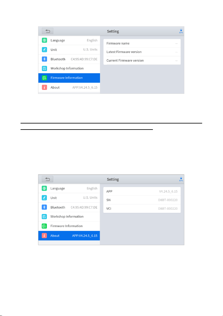
7.5. VCI FIRMWARE INFORMATION
You can view the VCI firmware information here, including the VCI firmware
name, the latest firmware version, the currently used firmware version, and
the VCI firmware type.
64
Figure 7-6 Sample of VCI Firmware Information
NOTE: To view the VCI firmware information, you need to enter the
diagnostic package first to get the VCI box to work.
7.6. ABOUT
Tap on ABOUT, you can check the serial number and APP version on here.
Figure 7-7 Sample of About Information
65
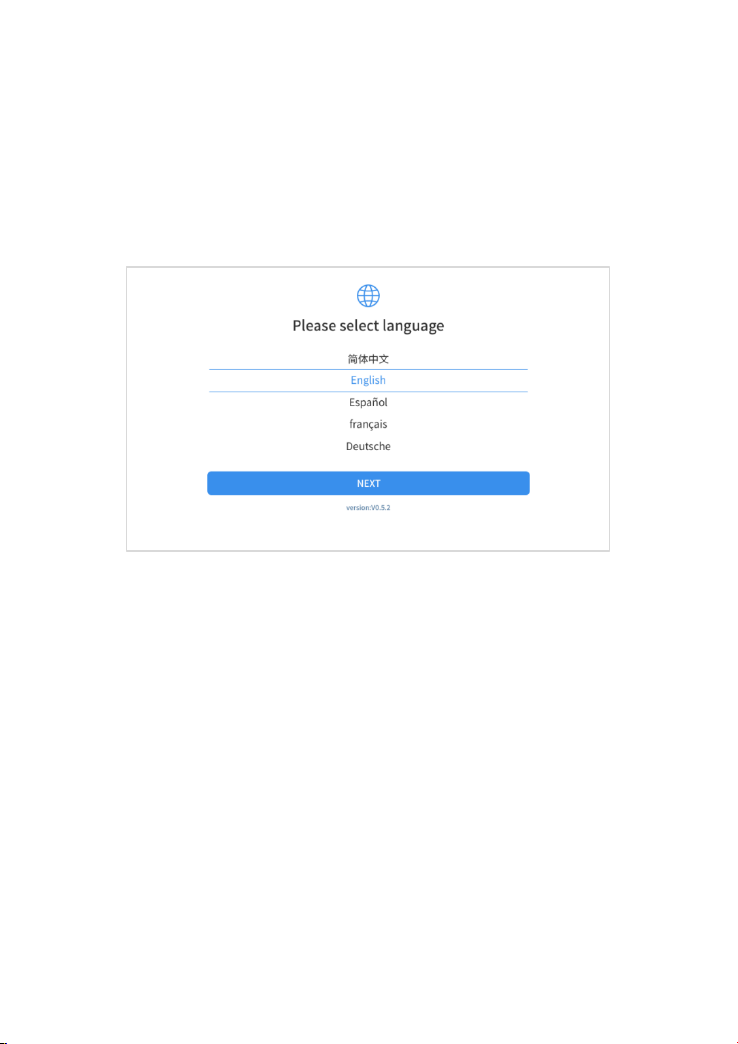
8 FACTORY RESET
After first-time users turn on the system, the system will automatically enter
the guide process and request the user to select the system operating
language.
Figure 8-1 Sample of Selecting Languages
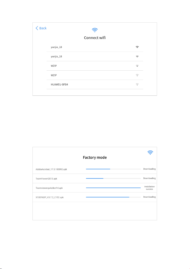
After selecting the system language, click Next to enter the Wi-Fi connection
page, as shown below:
66
Figure 8-2 Sample of Selecting Wi-Fi
Select a network to connect to on the Wi-Fi connection page.
After successful network connection, the automatic system will jump to
Factory mode to download the software:
Figure 8-3 Sample of Factory Mode
67
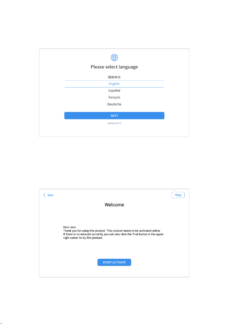
Once the software has been downloaded, the tablet will automatically reboot
and request the system language selection again.
Figure 8-4 Sample of Selecting Languages,Screen2
After setting the system language, you will enter the activation page, as
shown in the figure below. You can also click the "Trial" button in the upper
right corner to try it out before activation.
Figure 8-5 Sample of Activation, Screen 1
68
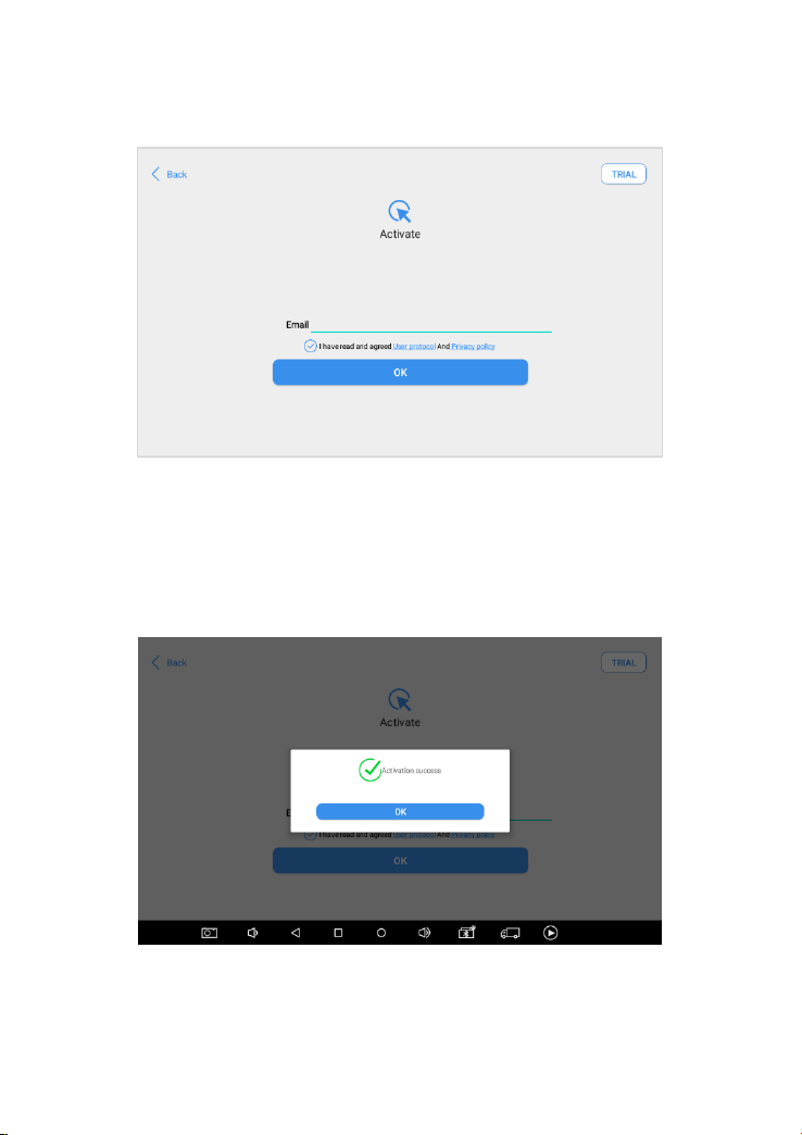
Click Start Activate to enter the activation page, as shown below:
Figure 8-6 Sample of Activation, Screen 2
A pop-up window showing Activation Success indicates that you have
completed the first boot setup, click OK to enter the diagnostic system and
start using the device.
Figure 8-7 Sample of Activation, Screen 3

69
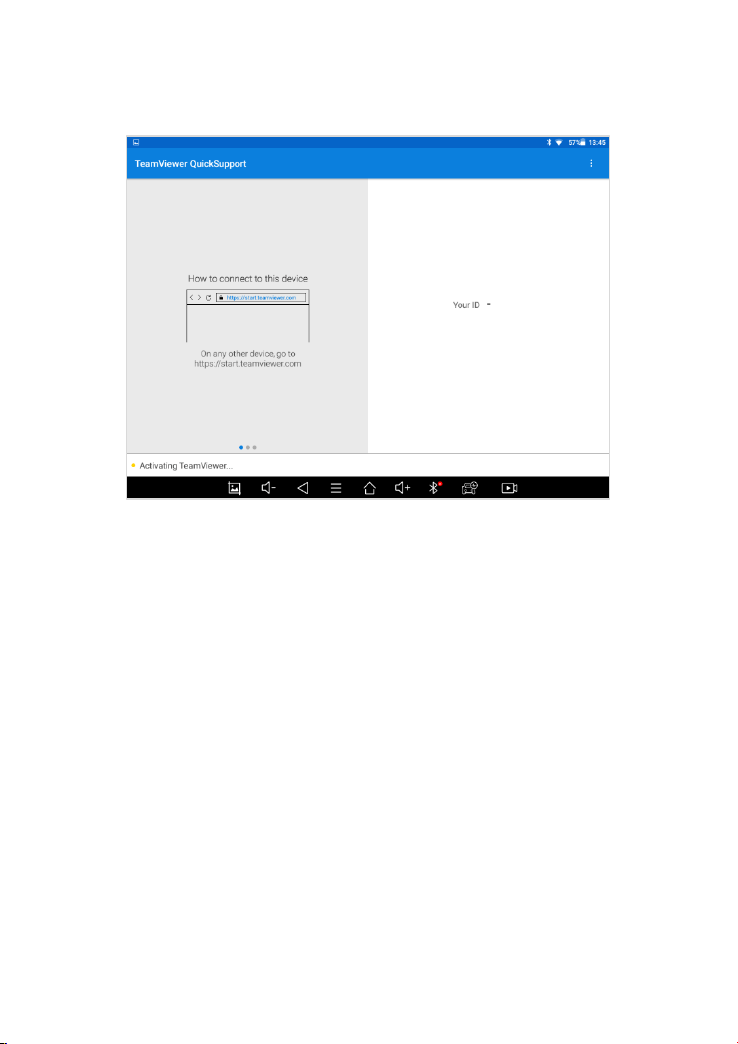
9 REMOTE ASSISTANCE
Tap on "Remote" to start the TeamViewer quick support program, which is
a simple, fast, and secure remote-control screen. You can use this
application to enable them to control your tablet on a PC through the
TeamViewer software, thereby obtaining temporary remote support from
Xtool's technical support centre.
Tablets and mobile devices running TeamViewer are identified by a globally
unique ID. When the remote application is started for the first time, the ID will
be automatically generated according to the hardware characteristics and
will not be changed in the future. This TeamViewer ID can individually access
all TeamViewer clients.
Before launching the remote desktop application, make sure that the tablet
is connected to the Internet so that you can access the tablet to receive
remote support from a third party. If you encounter problems and are not
able to solve them, you could open this application and ask for remote
assistance.
To obtain remote support from your partners or Xtool After-service Center:
1. Turn on the power of the tablet.
2. Click Remote in the diagnosis application. The TeamViewer screen is
displayed, and the device ID will be generated.
3. Your partner must install the remote-control software on his/her tablet by
downloading the full version of the TeamViewer program
(http://www.teamviewer.com) online, and then start the software on his/her
tablet at the same time, to provide support and remote control of the tablet.
4. Provide your ID to the partner or Xtool technician, and then wait for him/her
to send you a remote-control request.
5. A pop-up window will be shown asking you to confirm to allow the remote-
control program to control your device.
70
6. Click Allow to accept, or click Reject to reject.
Figure 9-1 Sample of Activating Team Viewer, Screen 1
71
10 FAQ
Q1: FAILED TO GENERATE DIAGNOSIS REPORT
1. Currently only perform diagnostic functions, that is, read ECU
information, read code and clear code, live data, freeze frame, which
can trigger a diagnostic report. Other functions, such as immobilization
and maintenance services will not be displayed in the report.
2. After entering the diagnosis menu, you need to perform one specific
function before the system can generate a diagnosis report normally.
After the diagnosis is completed, you need to step back to the previous
menu step by step to generate the diagnosis report successfully. If the
APP is killed directly, the report also cannot be triggered.
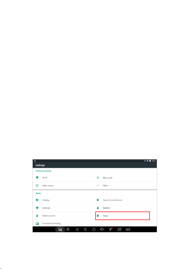
3. If the report still cannot be generated after troubleshooting according to
the above prompts, please try to exit the APP, enter the system settings,
and then choose to clear the APP cache.
Enter the path: Setting>>Apps>>Diagnosis>>Clear Cache
⚫ Sample as follows:
Fig 9-1 Sample1: How to clear APP cache
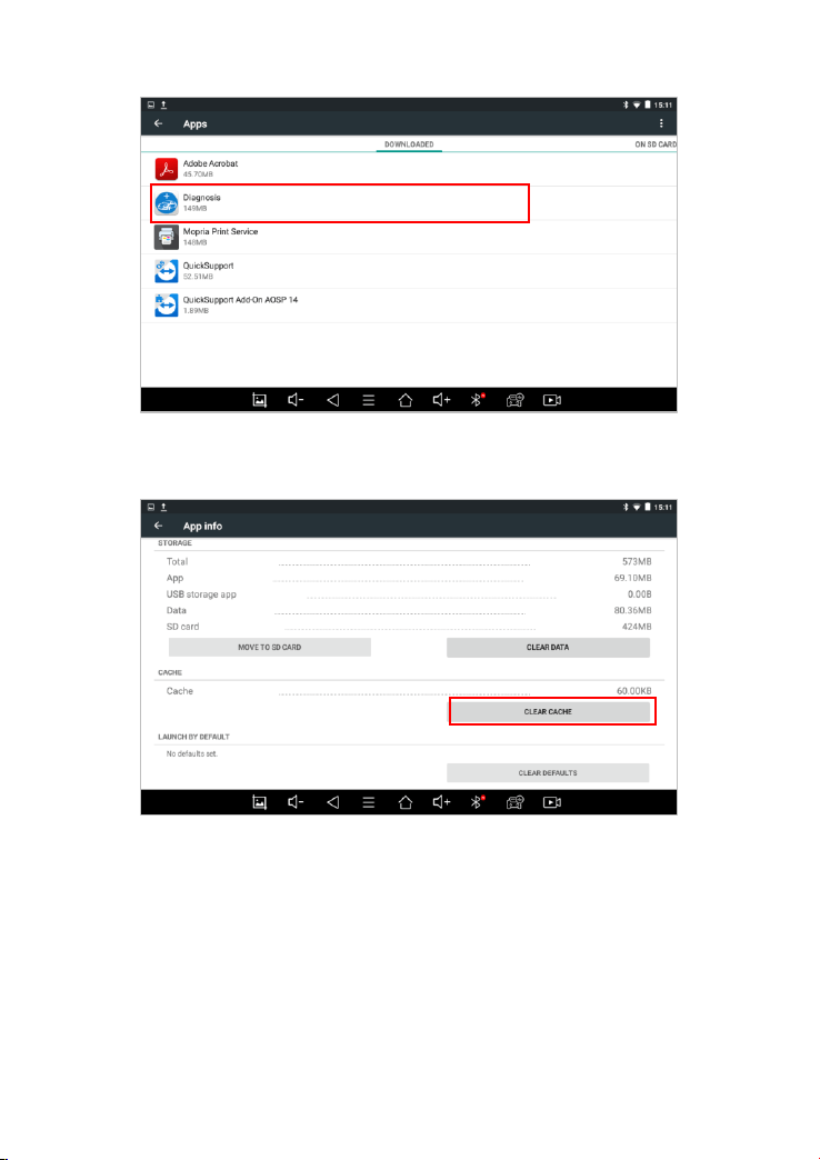
72
Fig 9-2 Sample1: How to clear APP cache
Fig 9-3 Sample1: How to clear APP cache
Q2: HOW TO PRINT DIAGNOSIS REPORT
The XTOOL device is compatible with third-party print drivers. You can
download the printer driver you need in the browser that comes with the
tablet to install it, and then set your printer in the OS settings. After the setting
is completed, you can print it in the Report.

73
Q3: FAILED TO EXTRACT FILES
Since the XTOOL tablet is equipped with an Android system, you have to
confirm the system type of receiver.
For Android: supports transferring files via Bluetooth, USB cable, etc.;
For IOS: only supports transferring files through a wired connection
(Bluetooth connection is not available).
Q4: MAILBOX SUPPORTED
The diagnosis tablet supports various mailboxes, including Hotmail, Outlook,
Yahoo, Gmail, etc. When you set up the email, please make sure that the
email client configuration address you entered is correct.
Due to the adjustment of Google's security policy, starting from May 31, 2022,
the Android system of this device will no longer support the email client to
log in to the Gmail account. To use the Gmail mailbox service, please log in
to the web version of Gmail using a browser.
Q5: HOW TO MAKE AN APPOINTMENT FOR REMOTE
SUPPORT
Please contact your dealer, or send an email to our technical support center.
(Email address: s[email protected]) And our technical support team
will confirm the time of remote support with you.
Q6: HOW TO GENERATE AND UPLOAD DIAGNOSTIC
LOG FILES
This tablet will automatically generate and store the diagnostic logs. When
the device is connected to the Internet, it will automatically upload all the
stored diagnostic logs to the backend system.

74
Q7: HOW TO SWITCH LANGUAGE
1. Contact your dealer and leave a message about the language you need
and the S/N of your device, The technician will modify the language
configuration for you in the backend system.
2. Settings->Language->Choose language
3. Back to Updates to update all the software again
Q8: FAILED TO DIAGNOSE VEHICLE
1. Contact your dealer to confirm whether the vehicle model is supported by
the scan tool you owned.
2. Check whether the vehicle is properly connected (e.g. whether the ignition
is ON, and the diagnosis of some vehicles need to turn on the engine), If
your tablet is equipped with a VCI box, please check the status of the VCI
box indicator.
3. Confirm whether you have entered the correct diagnosis menu.
4. Confirm whether the AUTO-SCAN function can assist you to enter the
correct diagnosis menu, or whether the OBDII function works.
5. Check whether the software is the latest version, if not, please update to
the latest version first.
Q9: FAILED TO ACTIVATE OR REGISTER
For ‘Activation Failed’
Generally caused by network instability, please switch to a more stable
network and try to activate again.
For ‘Registration Failed’
Generally, it is caused by the connection timeout or the sending timeout,
please check whether you have blocked the outgoing network traffic to non-

75
US regions like China. We recommend that you unblock and try to register
again.
Q10: FAILED TO TURN ON WHEN CHARGING
In the charging state, you need to first press the power button to light up the
screen (showing the charging status). Then press and hold the power button
for 4-5 seconds until the boot animation is shown on screen.
Q11: FAILED TO OPEN THE DIAGNOSIS APP
“With PROMPT ‘Sync your device. the device has been offline for more than
30 days. you should connect INTERNET SYNC DEVICES TO THE
NETWORK STATUS!’”
The tablet has to connect to the network every 30 days, otherwise, the
diagnosis app will be locked and disabled until the device is connected to the
network. If you have ruled out the network problem and ensured that the
device can be connected to the Internet normally, and your device still cannot
use the diagnostic function, please contact our technical team
Q12: FAILED TO ENTER VEHICLE MENU
If you encounter the following two prompts, please delete the package and
download it again to diagnose
‘Failed’
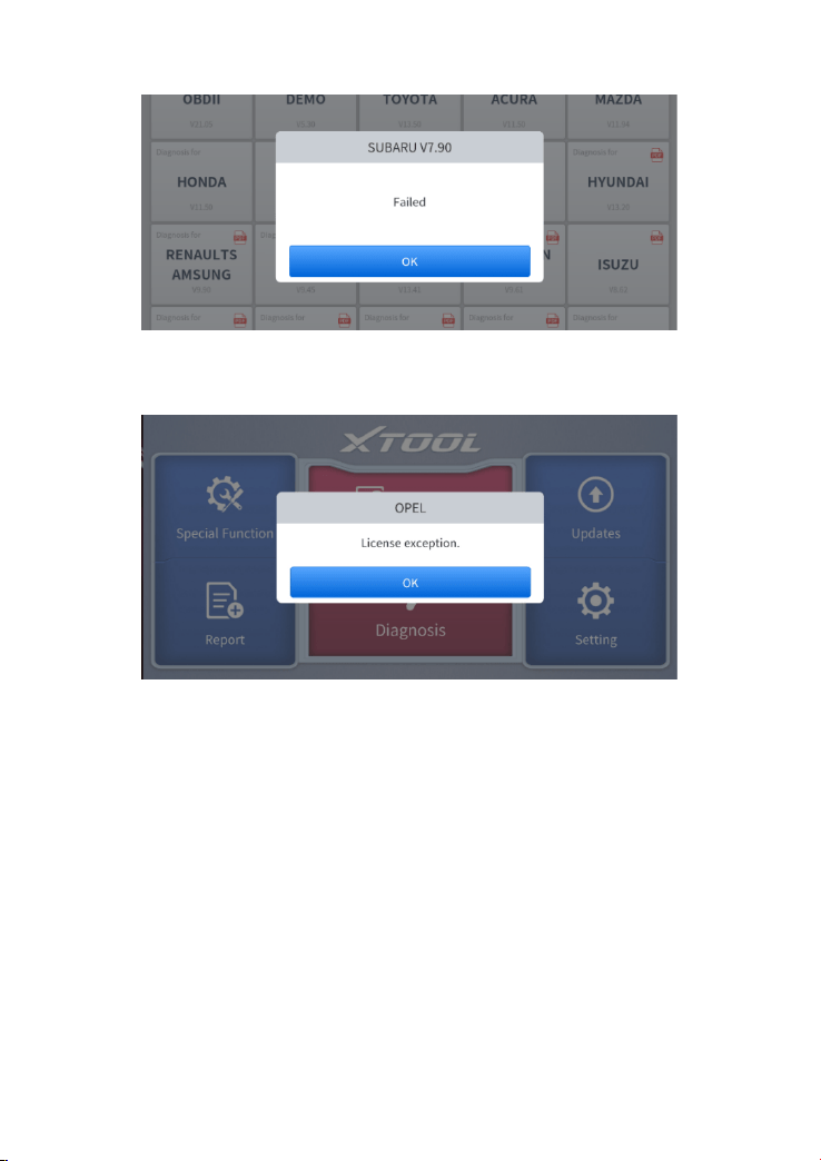
76
‘License exception’
11 WARRANTY & SERVICES
Shenzhen Xtooltech Intelligent Co., LTD.(the Company) warrants to the
original retail purchaser of this XTOOL device that should this product or any
part thereof during normal usage and under normal conditions be proven
defective in material or workmanship that results in product failure within one
year from the date of purchase, such defect(s) will be repaired, or replaced
(with new or rebuilt parts) with Proof of Purchase, at the Company’s option,
without charge for parts or labor directly related to the defect(s).
The Company shall not be liable for any incidental or consequential damages
arising from the use, misuse, or mounting of the device.

77
This warranty does not apply to:
1 Products subjected to abnormal use or conditions, accident,
mishandling, neglect, unauthorized alteration, misuse, improper
installation/repair or, improper storage;
2 Products whose mechanical serial number or electronic serial number
has been removed, altered, or defaced;
3 Damage from exposure to excessive temperature or extreme
environmental conditions;
4 Damage resulting from connection to, or use of any accessory or other
product not approved or authorized by the Company;
5 Defects in appearance, cosmetic, decorative, or structural items such
as framing and non-operating parts;
6 Products damaged from external causes such as fire, dirt, sand, battery
leakage, blown fuse, theft, or improper usage of any electrical source.

78
SHENZHEN XTOOLTECH INTELLIGENT CO., LTD
Company address: 17&18/F, Building A2, Creativity City, Liuxian
Avenue, Nanshan District, Shenzhen, China
Factory address: 2/F, Building 12, Tangtou Third Industrial Zone,
Shiyan Street, Baoan District, Shenzhen, China
Service-Hotline: 0086-755-21670995/86267858
Email: [email protected]
Fax: 0755-83461644
Website: www.Xtooltech.com

79