Please read and save these instructions. Read carefully before attempting to assemble, install, operate or maintain the product described.
Protect yourself and others by observing all safety information. Failure to comply with instructions could result in personal injury and/or prop.
erty damage! Retain instructions for future reference.
Air
Compressors
Description
Air compressorunits are intended to
provide compressedair to power pneu-
matic tools, operate sprayguns and sup-
plyair for pneumatic valves and actua-
tors. The pumps supplied with these
units have oil lubricated bearings. A
small amount of oil carryover ispresent
in the compressed air stream.
Applications requiring air free of oil
vapor should have the appropriate filter
installed. The air compressorunits are to
be mounted per the instructionsprovid-
ed on a solidfloor. Any other useof
these units will void the warranty and
the manufacturer will not be responsi-
ble for problems or damages resulting
from suchmisuse.Refer to the enclosed
"Replacement PartsManual" to identify
compressorassingle stage or two-stage.
Safety Guidelines
This manual containsinformation that is
very important to know and understand.
This information isprovided for SAFETY
and to PREVENTEQUIPMENTPROB-
LEMS.To help recognize this informa-
tion, observe the following symbols.
Danger indicates
an imminently haz.
ardous situation which, ff not avoided,
will result in death or serious injury.
I_WARNINGI Warningindicates
a potentially haz-
ardous situation which, if not avoided,
could result in death or serious injury.
Caution indicates a
[_CAUTIONI potentiallyhaz-
ardous situation which, if not avoided,
MAY result in minor or moderate
injury.
Notice indicates
I NOTICE l importantinforma-
tion, that if not followed, may cause
damage to equipment.
Unpacking
After unpacking the unit, inspect care-
fully for any damage that may have
occurred during transit. Make sureto
tighten fittings, bolts, etc., before
putting unit into service.
I WARNINGI Donotoperete
unit if damaged
during shipping, handling or use.
Damage may result in bursting and
causeinjury or property damage.
General Safety
Since the air compressorand other
components (material pump, spray
guns, filters, lubricators, hoses, etc.)
used make up a high pressure pump-
ing system, the following safety pre-
cautions must be observed at all times:
la amnu1
included with this
product carefully.
Bethoroughly
familiar with the controls and the
proper use of the equipment.
2. Follow all local electrical and safety
codes aswell as the United States
National Electrical Codes (NEC) and
Occupational Safety and Health Act
(OSHA).
3.Only personswellacquaintedwith
theserulesofsafeoperationshould
be allowedto usethe compressor.
4.Keep visitorsaway and NEVER
allowchildreninthe work area.
5.Wear safetyglassesand use
hearingprotectionwhen operating
the unit.
Breathable Air Warning
This compressor/pump isNOT
equipped and should NOT be used
"as is" to supply breathing quality
air. Forany application of air for
human consumption, you must fit
the air compressor/pump with suit-
able in-line safety and alarm equip-
ment. This additional equipment is
necessary to properly filter and puri-
fy the air to meet minimal specifica-
tions for Grade D breathing as
described in Compressed Gas
Association Commodity
Specification G 7.1 - 1966, OSHA 29
CFR1910. 134, and/or Canadian
Standards Associations (CSA).
DISCLAIMER OF WARRANTIES
In the event the compressor is used
for the purpose of breathing air
application and proper in-line safety
and alarm equipment is not simulta-
neously used, existing warranties
are void, and the company disclaims
any liability whatsoever for any
loss, personal injury or damage.
6. DO not stand on or usethe unit as
a handhold.
7. Before each use, inspect compressed
air system and electrical components
for signs of damage, deterioration,
weakness or leakage. Repair or
replace defective itemsbefore using.
8. Check all fasteners at frequent
intervals for proper tightness.
I REMINDER: Keep your dated proof of purchase for purposes! Attach it to this manual file it for I
warranty
or
safekeeping.
© 2003 Call 1-B00-543-6400 for parts IN254702AV 1/03
Call 1-800-54Z_-0350 for technical assistance
Air Compressors
General Safety (Cont.)
IAWARNINGI
Motors, electrical equip-
ment and controls can
cause electrical arcs that
will ignite a flammable gas or vapor.
Never operate or repair in or near a
flammable gas or yaps;, .AJ_verstore
flammable liquids or gases in the vicini-
ty of the compressor.
I WARNINGI
Never operate compressor
without a beltguard. This m_ Q j
unit can start automatically _Jh._
without warning. Personal
injury or property damage could occur
from contact with moving parts.
9. Do not wear loose clothing or jewel-
ry that will get caught in the mov-
ing parts of the unit.
AI - --0-TI 0 N I
Compressor parts may be
hot even if the unit is
stopped.
10. Keep fingers away from a running
compressor; fast moving and hot
parts will cause injury and/or burns.
11. If the equipment should start to
vibrate abnormally, STOPthe
engine/motor and check immediate-
ly for the cause. Vibration isgener-
ally an indication of trouble.
12. To reduce fire hazard, keep
engine/motor exterior free of oil,
solvent, or excessive grease.
IAWARNINGI AnASME Sa -
ty relief valve with a
setting no higher than the Maximum
Allowable Working Pressure (MAWP) of
the tank MUST be installed in the air lines
or in the tank for this compressor. The
ASME safety valve must have sufficient
flow and pressure ratings to protect the
pressurized components from bursting.
The flow rating can be found in the parts
manual. 7he safety valve in the intercool-
er does not provide system protection.
Maximum operat.
IACAUTIONI ingpre ureis,75
psi for two-stage compressors and 135
-150 psi for single stage compressors. DO
not Operate with pressure switch or pilot
valves set higher than 175 psi (two-stage)
or 135- 150 psi (single stage).
13. Never attempt to adjust ASME safe-
ty valve. Keep safety valve free from
paint and other accumulations.
Never attempt to repair or
modify a tank! Welding,
drilling or any other modi.
fication will weaken the
tank resulting in damage from rupture
or explosion. Always replace worn,
cracked or damaged tanks.
[ NOTICE ] Drainliquidfrom
tank daily.
14, Tanks rust from moisture build-up,
which weakens the tank, Make sure
to drain tank regularly and inspect
periodically for unsafe conditions
such as rust formation and corrosion.
15. Fastmoving air will stir up dust and
debris which may be harmful. Release
air slowly when draining moisture or
depressufizing the compressor system.
SPRAYING PRECAUTIONS
IAWARNINGI
Do not spray flammable
materials in vidnity of open
flame or near ignition
sources including the compressor unil_
16. Do not smoke when spraying paint,
insecticides, or other flammable
substances.
17. Use a face mask/respi-
rator when spraying
and spray in a well ven-
tilated area to prevent
health and fire hazards.
18. Do not direct paint or other sprayed
material at the compressor. Locate
compressor as far away from the spray-
ing area as possible to minimize over-
spray accumulation on the compressor.
19. When spraying or cleaning with sol-
vents or toxic chemicals, follow the
instructions provided by the chemi-
cal manufacturer.
Installation
I_WARNING]
Disconnect. tag and lock
out power source then
release all pressure from
the system before attempting to
install, service, relocate or perform any
maintenance.
[ACAUTION1 _ not lift or move
unit without appro.
priately rated equipment. Be sure the
unit is securely attached to lifting
device used. Do not lift unit by holding
onto tubes or coolers. Do not use unit
to lift other attached equipment.
Never use the
IACAUTIONI .oodshlpplng
skids for mounting the compressor.
install and operate unit at least 24"
from any obstructions in a clean, well
ventilated area. The surrounding air
temperature should not exceed 100° F.
This will ensure an unobstructed flow
of air to cool compressor and allow
adequate space for maintenance.
Do not locata the
compressor air inlet
near steam, paint spray, sandblast areas
or any other source of contamination.
NOTE: If compressor operates in a hot,
moist environment, supply compressor
pump with clean, dry outside air.
Supply air should be piped in from
external sources.
TANK MOUNTING
The tank should be bolted into a flat,
even, concrete floor or on a separate
concrete foundation, Vibration isolators
should be usedbetween the tank leg
and the floor. Model MP345800AJ isola-
tor padsare recommendedfor horizon*
tal units. Model MP345700AJisolator
padsare recommended for vertical units.
When using isolatorpads,do not draw
bolts tight. Allow the padsto absorb
vibrations.When isolatorsare used,a
flexible hoseor coupling should be
installed between the tank and service
piping.
[AWARNINGI
Failure to properly install
the tank can lead to cracks
at the welded joints and
possible bursting.
PIPING
IAWARNINGI Neveruseplastic
(PVC) pipe for corn-
pressed air. Serious injury or death
could result.
Any tube, pipe or hoseconnected to the
unit must be able to withstand the tem-
perature generated and retain the pres-
sure. All pressurized components of the
air system must have a pressure rating
higher than or equal to the 200 psi for
2
Cast Iron Series
Installation (Cont.)
t_vo-stage compressors or 150 psi for sin-
g]e stage compressors ASME safety valve
setting. Incorrect selection and installa-
tion of any tube, pipe or hose could result
in bursting and injury. Connect piping sys-
tem to tank using the same size fitting as
the discharge port.
INSTALLING A SHUT-OFF VALVE
A shut-off valve should be installed on
the discharge port of the tank to control
the air flow out of the tank. The valve
should be located between the tank and
the piping system.
IAWARNINGI Neverinstalla
shut-off valve
between the compressor pump and the
tank. Personal injury andlor equipment
damage may occur. Never use reducers
in discharge piping.
When creating a permanently installed
system to distribute compressed air, find
the total length of the system and select
pipe size from the chart. Bury under-
ground lines below the frost line and
avoid pockets where condensation can
gather and freeze.
Apply air pressure to the piping installa-
tion and make sureall joints are free
from leaksBEFOREunderground lines
are covered. Before putting the compres-
sorinto service, find and repair all leaks
in the piping, fittings and connections.
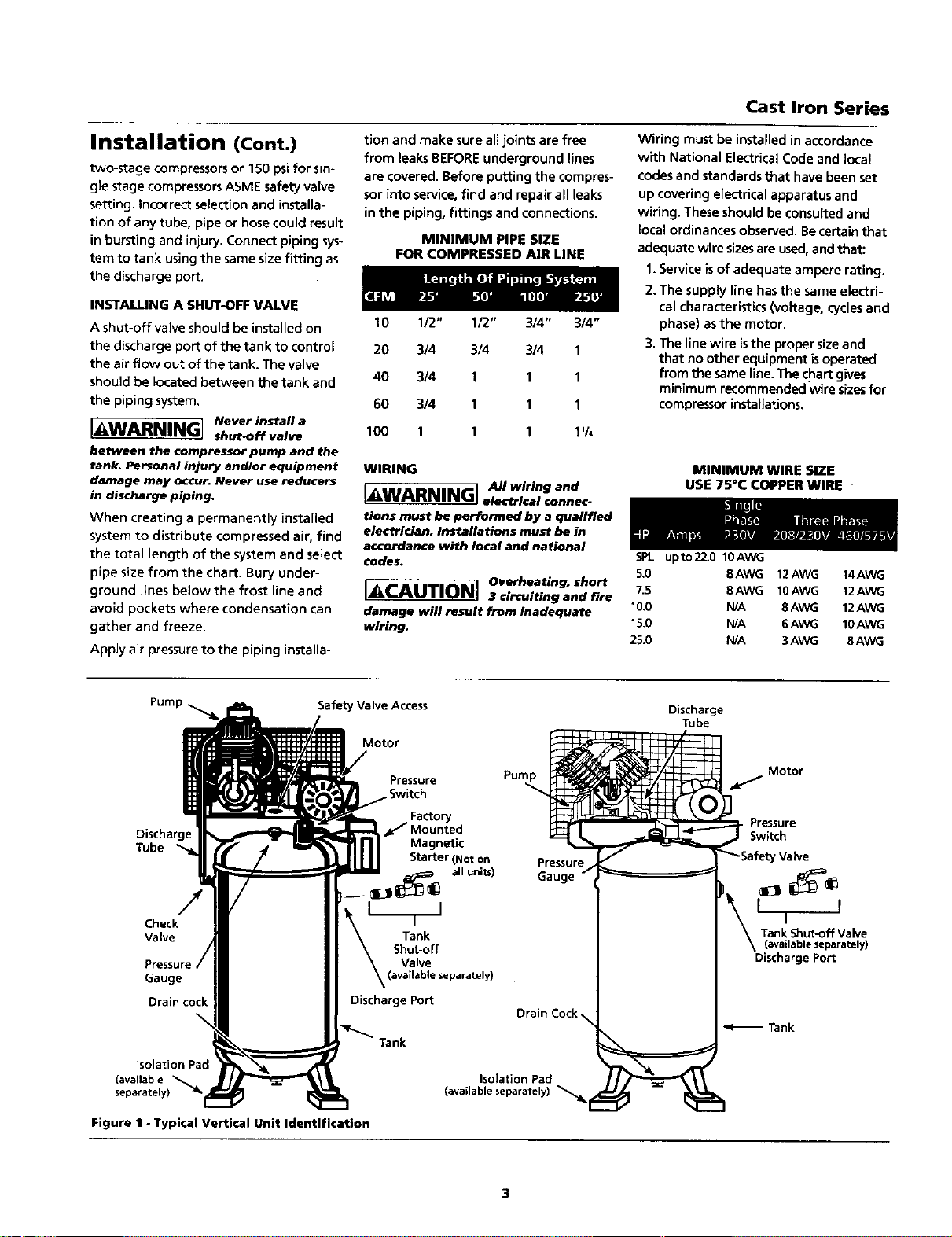
MINIMUM PIPE SIZE
FOR COMPRESSED AIR LINE
10 1/2" 1/2" 3/4" 3/4"
20 314 3/4 3/4 1
40 314 1 1 I
60 3/4 1 1 1
100 1 1 1 1'/4
WIRING
[AWADPj,mjr. I All wiring and
a_'alaal'_'Wl electrical connec-
tions must be performed by a qualified
electrician. Installations must be in
accordance with local and national
codes.
IACAUTIO- Overheating. short
3 circuiting and fire
damage will result from inadequate
wiring.
Wiring must be installed in accordance
with National Electrical Code and local
codes and standards that have been set
up covering e[ectrical apparatus and
wiring. These should be consulted and
Eocalordinancesobserved. Becertainthat
adequate wire sizesare used,and that:
1.Serviceisof adequate ampere rating.
2. The supply line hasthe sameelectri-
cal characteristics(voltage, cyclesand
phase) asthe motor.
3. The line wire isthe proper sizeand
that noother equipment isoperated
from the same line.The chartgives
minimum recommended wire sizesfor
compressorinstallations.
MINIMUM WIRE SIZE
USE 75°C COPPER WIRE
5PL upto22.0 10AWG
S.0 8AWG 12AWG t4AWG
7.5 8AWG 10AWG 12AWG
10.0 HA 8AWG 12AWG
15.0 HA 6AWG 10AWG
25.0 HA 3AWG 8AWG
Pump
Safety Valve Access
Motor
Discharge
Tube
/
Check
Valve
Gauge
Drain cock
Pressure
,Switch
Factory
_" Mounted
Magnetic
Starter (Not on
_ all units)
__eparately)
Discharge Port
Isolation Pad
(available
separate
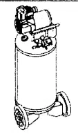
Figure 1 - Typical Vertical Unit Identification
Discharge
Tube
Pump
Motor
Pressure
Switch
Pressure Valve
Gauge _
Discharge Port
Drain Cock
_<_ Tank
o__,a, olat o2Pad
3
Air Compressors
Installation (Cont.)
Recommended wire sizesmay be larger
than the minimum set up by localordi-
nances. If so, the larger size wire should
be used to prevent excessive line voltage
drop. The additional wire cost isvery
small compared with the cost of repair-
ing or replacing a motor electrically
"starved" bythe use of supply wires
which are too small.
GROUNDING
electrical components are] _ I
shock hazards. Make sure I _ J
all the components are
properly grounded toprevent death or
serious injury.
Thisproduct must be grounded.
Grounding reducesthe risk of electrical
shock by providing an escapewire for
the electric current if short circuit
occurs. This product must be installed
and operated with a power cord or
cable that has a grounding wire.
MOTOR HOOKUP AND STARTER
INSTALLATION
Branch circuit protection must be provid-
ed asspecified in the United States
National Electrical Code, Chapter 2,
"Wiring Design and Protection." Article
210, using the applicable article "For
Motors and Motor Controllers," (Article
430, Table 430-1 52).
IMPORTANT: Overload protection is
required for all motors, Certain motors
Pump
Discharge
Tube
-,,,,
Check Valve
\
Tank
Pressure
Gauge
Isolation Pad
(available separately) •
/
Drain cock
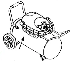
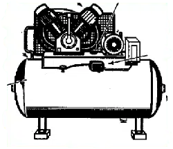
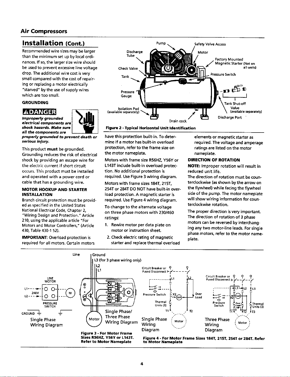
Figure 2 - Typical Horizontal Unit Identification
have this protection built-in. To deter-
mine if a motor has built-in overload
protection, refer to the frame size on
the motor nameplate.
Motors with frame size RS6HZ,Y56Y or
L143T include built-in overload protec-
tion. No additional protection is
required. Use Figure 3 wiring diagram•
Motors with frame sizes 184T, 21ST,
254T or 284T DO NOT have built-in over-
load protection. A magnetic starter is
required. Use Figure 4 wiring diagram.
To change to the alternate voltage
on three phase motors with 2301460
ratings:
I. Rewire motor per data plate on
motor or instruction sheet.
2. Check electric rating of magnetic
starter and replace thermal overload
Safety Valve Access
Motor
Factory Mounted
J Magnetic (Not on
Starter
r all units)
Pressure Switch
Tank Shut-off
Valve
(avaUabie separately)
Discharge Port
elements or magnetic starter as
required. The voltage and amperage
ratingsare listed onthe motor
nameplate.
DIRECTION OF ROTATION
NOTE: Improper rotation will result in
reduced unit life.
The direction of rotation must be coun-
terclockwise (asshown bythe arrow on
the flywheel) while facing the flywheel
sideof the pump. The motor nameplate
will show wiring information for coun-
terclockwise rotation.
The proper direction is very important.
The direction of rotation of 3 phase
motors can be reversed by interchang-
ing any two motor-line leads. Forsingle
phase motors, refer to the motor name-
plate.
Line
LINE
MOTOR f_
._
PRESSURE
SWITCH
GROUND --1-_
Single Phase
Wiring Diagram
Ground
ii L3 (for 3 phasewiring only}
I 1.2
Circult Breaker or (_
L1 Fused Disconnect I-i1_ .....
_-J Single Phase/
Q1otc r_ Three Phase
Wiring Diagram Wiring
Diagram
Figure 3 - For Motor Frame
Sizes RS6HZ,Y56Y or L143T.
Refer to Motor Nameplate
......... _L1
'_-_ .... '_T2
Pres ure Sw tch ' X2 Over
'- Load
Thermal
Units (3)
T1
J
Single Phase , Motor',
Circuit Breaker or ? _
Fused Disconnect I- f- --_z_ _y
I I
: L__L1 L_l L3
Pressure _ rnermal
Switch tUnits (3)
• • T3
Three Phase .'
Wiring ,,,Motor
Diagram
Figure 4 - For Motor Frame Sizes 184T0 215T, 254T or 284T. Refer
to Motor Nameplate
4
Operation
IMPORTANT: Check motor rotation
before operating the compressor.
All lubricated compressor pumps dis-
charge some condensed water and oil
with the compressed air. Install appro-
priate water/oil removal equipment
and controls asnecessaryfor the
intended application.
Failure to install
I NOTICE I a_onate
waterloil removal equipment may result
in damage to ma(hinery or workpiece.
GUARDING
The belt guard provided
must be installed before
operating the unit.
All moving parts must be guarded. All
electrical covers must be installed
before turning on the power.
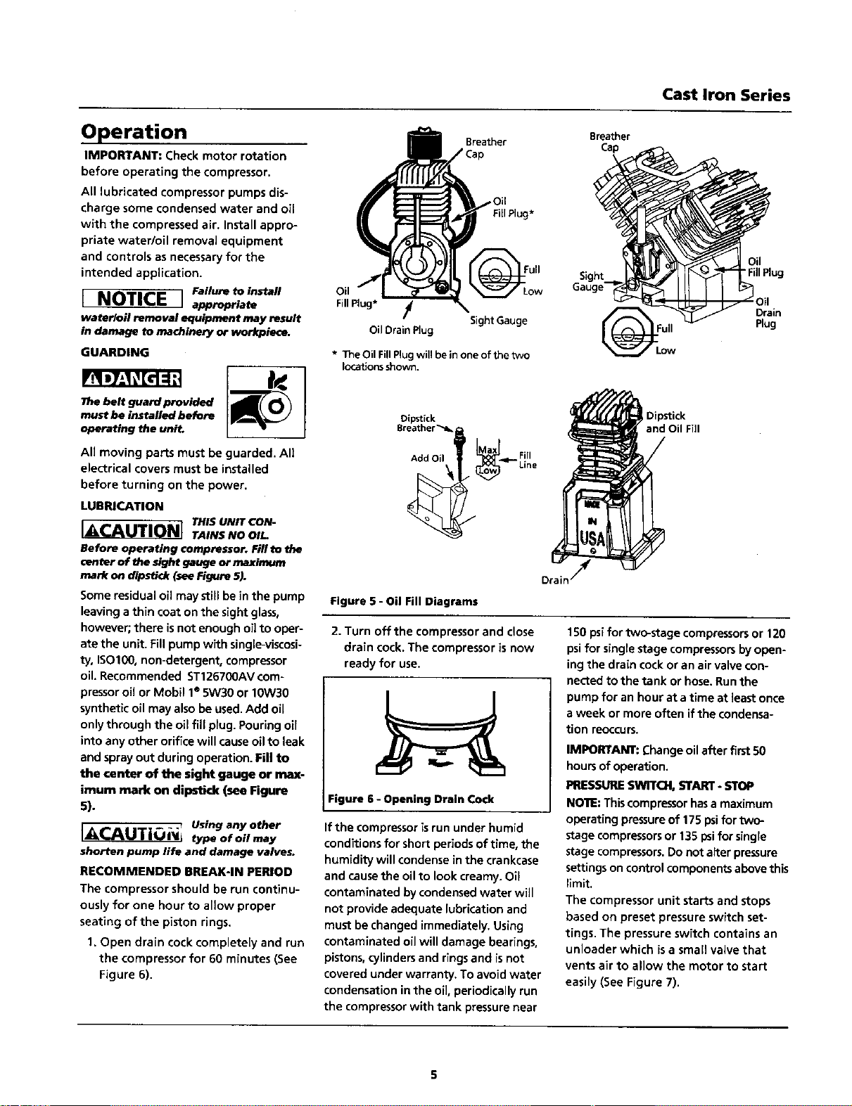
LUBRICATION
THIS UNIT CON-
I_CAUTIONI TAINSNOOI--
Before operating compressor. Fillto the
center of the sight gauge or maximum
mark on dipst_ (see_gure 5).
Some residualoil may still bein the pump
leaving athin coat on the sight glass,
however; there isnot enough oil to oper-
ate the unit. Fillpump with single-viscosi-
ty, ISO100, non-detergent, compressor
oil. Recommended ST126700AVcom-
pressor oil or Mobil 1" 5W30 or 10W30
synthetic oil may also be used.Add oil
onlythrough the oil fill plug. Pouring oil
into any other orifice will causeoil to leak
and spray out during operation. Fill to
the center of the sight gauge or max-
imum mark on dipstick (see Figure
5).
IACAUTiONI Usinganyother
type of oil may
shorten pump life and damage valves.
RECOMMENDED BREAK-IN PERIOD
The compressor should be run continu-
ously for one hour to allow proper
seating of the piston rings.
1. Open drain cock completely and run
the compressor for 60 minutes (See
Figure 6).
Cast Iron Series
Breather Breather
Cap
Oil
Fill
Plug*
SightGauge
OilDrainPlug
* The Oil FillPlug will be inone of thetwo
locationsshown.
ull
_il
"Fill Plug
Drain
Plug
Dipstick
Breather_
Add Oil Max _ F!II
I Dipstick
and Oil Fill
Figure 5 - Oil Fill Diagrams
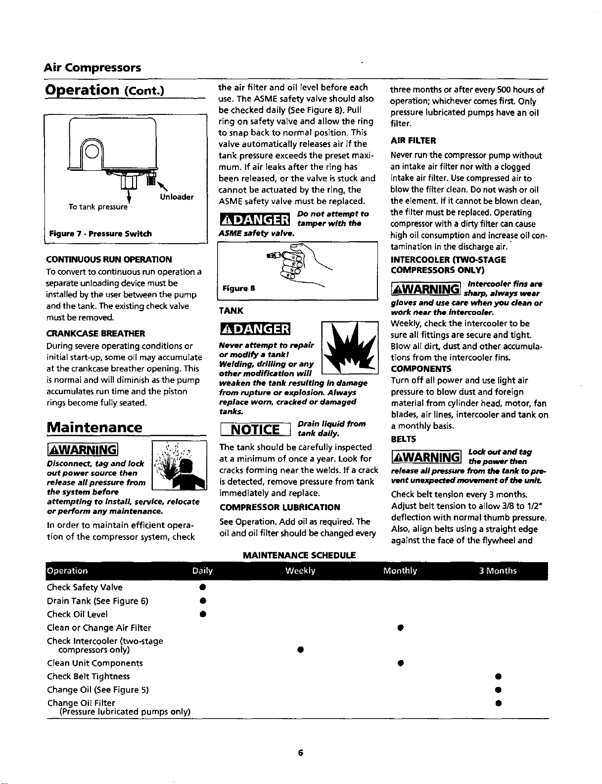
2. Turn off the compressor and close
drain cock. The compressor is now
ready for use.
Figure 6 - Opening Drain Cock
If the compressorisrun under humid
conditions for short periods of time, the
humidity will condense in the crankcase
and causethe oil to look creamy. Oil
contaminated by condensed water will
not provide adequate lubrication and
must be changed immediately. Using
contaminated oil will damage bearings,
pistons, cylinders and rings and isnot
covered under warranty. To avoid water
condensation in the oil, periodically run
the compressor with tank pressure near
150 psifor two-stage compressorsor 120
psi for singlestage compressorsby open-
ing the drain cockor an air valve con-
netted to the tank or hose.Runthe
pump for an hour at atime at least once
aweek or more often if the condensa-
tion reoccurs.
IMPORTANT: Change oil after first50
hoursof operation.
PRESSURESWITCH, START- STOP
NOTE:Thiscompressor hasa maximum
operating pressureof 175 psifortwo-
stage compressorsor 135 psifor single
stagecompressors. Do not alter pressure
settingsoncontrol components above this
limit.
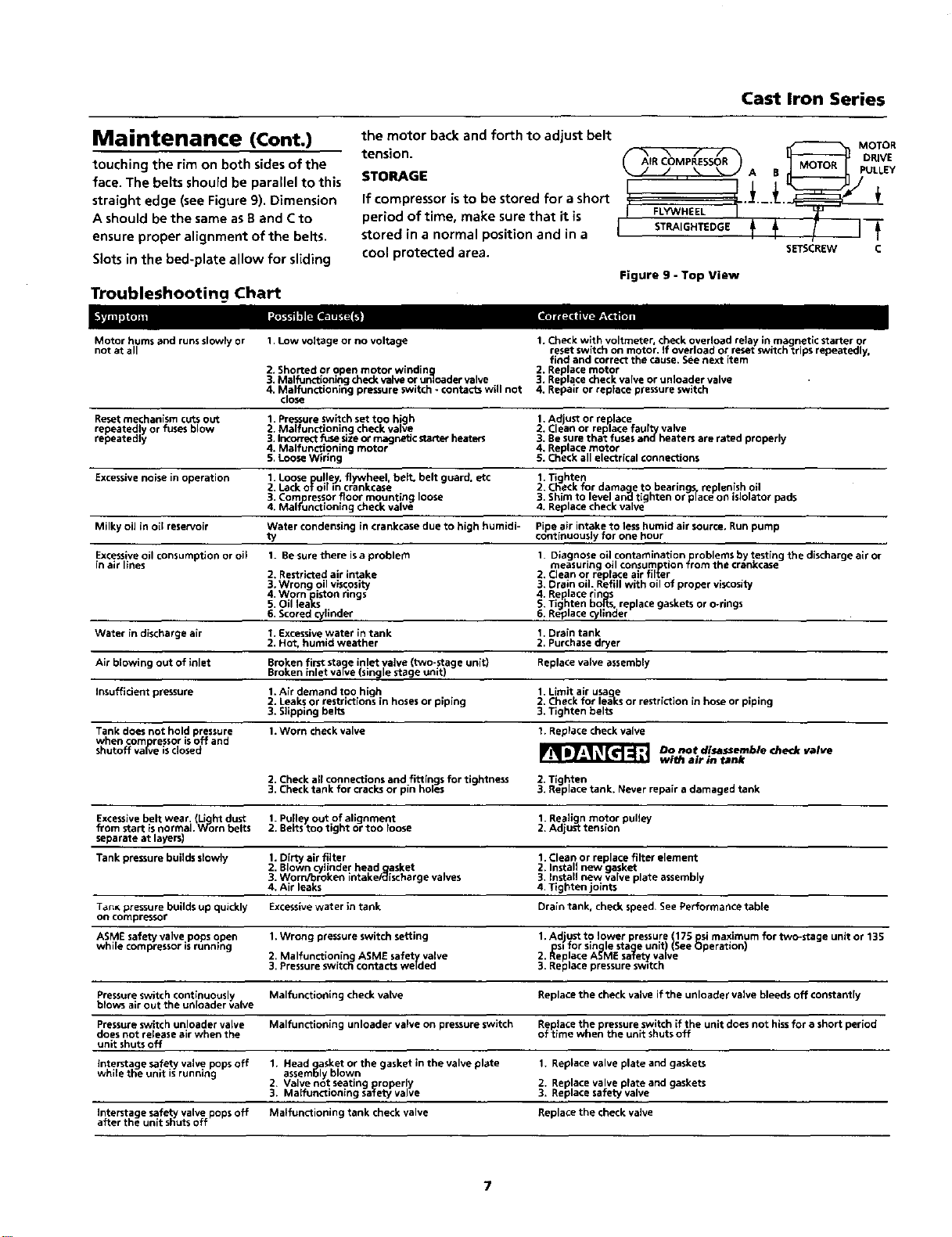
The compressor unit starts and stops
based on preset pressureswitch set-
tings. The pressure switch contains an
unloader which isa small valve that
vents air to allow the motor to start
easily (See Figure 7).
Air Compressors
Operation (Cont.)
Unloader
Totank pressure
Figure 7 - Pressure Switch
CONTINUOUS RUN OPERATION
To convert to continuous run operation a
separate unloading device must be
installedby the userbetween the pump
and the tank. The existingcheck valve
must be removed.
ORANKCASE BREATHER
During severe operating conditions or
initial start-up, some oil may accumulate
at the crankcase breather opening. This
isnormal and will diminish asthe pump
accumulates run time and the piston
ringsbecome fully seated.
Maintenance
I W.=d NINGI
Disconnect, tag and lock
out power source then
release all pressure from
the system before
attempting to install, service, relocate
or perform any maintenance.
In order to maintain efficient opera-
tion of the compressor system, check
the air filter and oil level before each
use. The ASME safety valve should also
be checked daily (See Figure 8). Pull
ring on safety valve and allow the ring
to snap back to normal position, This
valve automatically releases air if the
tank pressure exceeds the preset maxi-
mum. If air leaks after the ring has
been released, or the valve isstuck and
cannot be actuated by the ring, the
ASME safety valve must be replaced.
Do not attempt to
tamper with the
ASME safety valve.
Figure 8
TANK
Never attempt to repair
or modify a tank!
Welding, drilling or any
other modification will
weaken the tank resulting in damage
from rupture or explosion. Always
replace worn, cracked or damaged
tanks.
Drain liquid from
I NOTICE J tank daily.
The tank should be carefully inspected
at a minimum of once a year. Look for
cracks forming near the welds, if a crack
isdetected, remove pressurefrom tank
immediately and replace.
COMPRESSOR LUBRICATION
See Operation. Add oil asrequired. The
oil and oil filter should be changed every
three months or after every SO0hoursof
operation; whichever comesfirst.Only
pressure lubricated pumps have an oil
filter.
AIR FILTER
Never run the compressorpump without
an intake air filter norwith aclogged
intake air filter. Usecompressedair to
blow the filter clean. Do not wash or oil
the element. If it cannot be blown clean,
the filter mustbe replaced.Operating
compressorwith a dirty filter cancause
high oil consumptionand increase oil con-
tamination inthe dischargeair.
INTERCOOLER (TWO-STAGE
COMPRESSORS ONLY)
r IAIADAIIAII_-] Intercooler fins are
L_WA..s,,._=j sharp,alwayswear
gloves and use care when you clean or
work near the Intercooler.
Weekly, check the intercooler to be
sure all fittings are secureand tight.
Blow all dirt, dust and other accumula-
tions from the intercooler fins.
COMPONENTS
Turn off all power and use light air
pressureto blow dust and foreign
material from cylinder head, motor, fan
blades, air lines, intercooler and tank on
a monthly basis.
BELTS
[_WARNING] Lo<koutandtag
the power then
release all pressure from the tank to pre-
vent unexpected movement of the uni_
Check belt tension every 3 months.
Adjust belt tension to allow 3/8 to 1/2"
deflection with normal thumb pressure.
Also, align belts using a straight edge
against the face of the flywheel and
MAINTENANCE SCHEDULE
Check Safety Valve
Drain Tank (See Figure 6)
Check Oil Level
Clean or Change Air Filter
Check Intercooler (two-stage
compressorsonly)
Clean Unit Components
Check Belt Tightness
Change Oil (See Figure 5)
Change OiEFilter
(Pressure lubricated pumps only)
O
O
O
e
o
6
Cast Iron Series
Maintenance (Cont.)
touching the rim on both sides of the
face. The belts should be parallel to this
straight edge (see Figure 9), Dimension
A should be the same as B and Cto
ensure proper alignment of the belts.
Slotsin the bed-plate allow for sliding
Troubleshooting Chart
the motor back and forth to adjust belt
MOTOR
tension. _ _ _ f f _ DRIVE
AIR COMPRESSOR
STORAGE I J \ '_= A B PULLEY
i i
If compressor isto be stored for a short , ".]_._._..
period of time, make sure that it is FLYWHEEL I
stored in a normal position and in a I STRAIGHTEDGE
cool protected area. SETSCREW C
Figure 9 - Top View
Motor hums and runsslowly or
not at all
1,Low voltage or no voltage
2. Shorted or open motor wlndin _g
3. Malfunctioning check valve or unloader valve
4. Malfunctioning pressure switch - contacts will not
close
1. Check with voltmeter, check overload relay in magnetic starter or
reset switch on motor• If overload or reset switch trips repeatedly.
find and correct the cause. See next item
2. Replace motor
3. Replace check valve or unloader valve
4. Repair or replace pressure switch
Reset mechanism cuts out
repeatedly or fuses blow
repeatedly
1. Pressure switch set too high
2. Malfunctioning check valve
3. Incorrect fuse sizeor magnetic starter heetefs
4. Malfunctioning motor
5. Loose Wiring
1.Adjust or replace
2. Clean or replace faulty valve
3. Be sure that fuses andheaters are rated properly
4. Replace motor
5. Check all electrical connections
Excessivenoise in operation
1. Loose pulley flywheel belt, belt guard etc
2. Lack OTO m crankcase
3. Comlpressorfloor mounting loose
4. Malfunctioning check valve
1. Tighten
2. Check for damaaan_eto bearingis, replenish oil
3. Shim to level tighten or place on islolator pads
4. Replace check valve
Milky oil in oil reservoir Water condensing in crankcase due to high humidi- Pipe air intake to less humid air source, Run pump
ty continuously for one hour
Excessiveoil consumption or oil
in air lines
Water in discharge air
1. Be sure there is a problem
2. Restricted air intake
3.Wrong oil viscosity
4. Worn iston rings
5. Oil lea_s
6, Scored o/linder
I. Excessivewater in tank
2. Hot, humid weather
I. Diagnose oil contamination roblems by testing the discharge air or
measuring oil consumption _rom the crankcase
2. Clean or replace alt filter
3. Drain oil. Refill with oil of proper visCosity
4. Replace ringss
g. Tighten bo_ts replace gaskets or o-tlngs
6. Replace c_/ nder
1. Drain tank
2. Purchase dryer
Air blowing out of inlet
Insufficient pressure
Broken first stage inlet valve (t_vo-stage unit)
Broken inlet vaFve(single stage unit)
1. Air demand too high
2. Leaks or restrictions in hosesor piping
3. Slipping belts
Replace valve assembly
1. Limit air usaoEe
2. Check for lea-ksor restriction in hose or piping
3. Tighten belts
Tank does not hold pressure 1.Worn check valve t. Replace check valve
when corno ressor isoff and
shutoff va(ve isdosed
Do not disassemble check valve
with air in tank
2, Check allconnections and fittings for tightness 2. Tighten
3. Check tank for cracks or pin holes 3. Replace tank. Never repair a damaged tank
Excessivebelt wear. Light dust 1.Puney out of alignment 1. Realign motor pulley
from start isnorma. Worn belts 2. Belts too tight or too loose 2. Adjust tension
separate at layers)
Tank pressure builds slowly 1.Dirty air filter 1, Clean or replace filter element
2. Blown cylinder head gasket 2. Install new gasket
3. Worn/broken intake/c_ischarge valves 3. Install new valve plate assembly
4, Air leaks 4. Tighten joints
Tan_ pressure builds up quickly Excessivewater in tank Drain tank. check speed. See Performance table
on compressor
ASME safety valve pops open 1.Wrong pressure switch setting 1,Adjust to lower pressure 175 psi maximum for two-stage unit or 135
• " psi for single stage unltI See Operation
while compressor Bsrunning 2. Malfunctioning ASME saffety valve 2. Replace ASME saTetyvalve
3, Pressure switch contacts welded
3. Replace pressure switch
Pressure switch continuously Malfunctioning check valve Replace the check valve if the unloader valve bleeds off constantly
blows air out the unloader valve
Pressure switch unloader valve Malfunctioning unloader valve on pressure switch Replace the pressure switch if the unit does not hissfor a short period
does not release air when the of time when the unit shuts off
unit shuts off
Interstage safety valve pops off 1. Head gasket or the gasket in the valve plate 1. Replace valve plate and gaskets
while the unit isrunning assembly blown
2. Valve not seating prroperly 2. Replace valve plate and gaskets
3. Maifunctlonlng safety valve 3. Replace safety valve
Interstage safety valve pops off Matfunctioning tank check valve Replace the check valve
after the unit shuts off
Air Compressors
Limited Warranty
Cast Iron Series
1. DURATION: From the date of purchase by the original purchaser as follows: Standard Duty - One Year; Serious Duty - Two
Years; Extreme Duty - Three Years; Maxus Model Series - Five Years.
2. WHO GIVES THIS WARRANTY (WARRANTOR):
Campbell Hausfeld / Scott Fetzer Company, 100 Production Drive, Harrison, Ohio, 45030, Telephone: (800) 543-6400
3. WHO RECEIVES THIS WARRANTY (PURCHASER): The original purchaser (other than for purposes of resale) of the Campbell
Hausfeld compressor.
4. WHAT PRODUCTS ARE COVERED BY THIS WARRANTY; Any Campbell Hausfeld air compressor.
5. WHAT IS COVERED UNDER THIS WARRANTY: Substantial defects due to material and workmanship with the exceptions
noted below.
6. WHAT IS NOT COVERED UNDER THIS WARRANTY:
A. implied warranties, including those of merchantability and FITNESS FOR A PARTICULAR PURPOSE ARE LIMITED FROM
THE DATE OF ORIGINAL PURCHASE AS STATED IN THE DURATION. if this compressor is used for commercial, industrial or
rental purposes, the warranty will apply for ninety (90) days from the date of purchase. Extreme Duty Contractor
Compressors are not limited to a ninety (90) day warranty when used in contractor applications. Four cylinder single-
stage and two-stage compressors are not limited to a ninety (90) day warranty when used in commercial or industrial
applications. Some States do not allow limitations on how long an implied warranty lasts, so the above limitations may
not apply to you.
B. ANY INCIDENTAL, INDIRECT, OR CONSEQUENTIAL LOSS, DAMAGE, OR EXPENSE THAT MAY RESULT FROM ANY DEFECT,
FAILURE, OR MALFUNCTION OF THE CAMPBELL HAUSFELD PRODUCT. Some States do not allow the exclusion or limita-
tions of incidental or consequential damages, so the above limitation or exclusion may not apply to you.
C. Any failure that results from an accident, purchaser's abuse, neglect or failure to operate products in accordance with
instructions provided in the owner's manual(s) supplied with compressor.
D. Pre-delivery service, i.e. assembly, oil or lubricants, and adjustment.
E. Items or service that are normally required to maintain the product, i.e. lubricants, filters and gaskets, etc.
F. Gasoline engines and components are expressly excluded from coverage under this limited warranty. The Purchaser
must comply with the warranty given by the engine manufacturer which issupplied with the product.
G, Additional items not covered under this warranty:
1. All Compressors
a. Any component damaged in shipment or any failure caused by installing or operating unit under conditions not in
accordance with installation and operation guidelines or damaged by contact with tools or surroundings.
b. Pump or valve failure caused by rain, excessive humidity, corrosive environments or other contaminants.
c. Cosmetic defects that do not interfere with compressor functionality.
d. Rusted tanks, including but not limited to rust due to improper drainage or corrosive environments.
e. Electric motors, check valves and pressure switches after the first year of ownership.
f. Drain cocks.
g. Damage due to incorrect voltage or improper wiring.
h. Other items not listed but considered general wear parts.
i. Pressure switches, air governors and safety valves modified from factory settings.
2. Lubricated Compressors
a. Pump wear or valve damage caused by using oil not specified.
b. Pump wear or valve damage caused by any oil contamination or by failure to follow proper oil maintenance
guidelines.
3. Belt Drive / Direct Drive / Gas Driven Compressors
a. Belts.
b. Ring wear or valve damage from inadequate filter maintenance.
c. Manually adjusted load/unload and throttle control devices.
7. RESPONSIBILITIES OF WARRANTOR UNDER IHIS WARRANTY: Repair or replace, at Warrantor's option, compressor or com-
ponent which is defective, has malfunctioned and/or failed to conform within duration of the warranty period.
8. RESPONSIBILITIES OF PURCHASER UNDER THIS WARRANTY:
A. Provide dated proof of purchase and maintenance records.
B. Portable compressors or components must be delivered or shipped to the nearest Campbell Hausfeld Authorized Service
Center. Freight costs, if any, must be borne by the purchaser,
C. Use reasonable care in the operation and maintenance of the products as described in the owner's manual(s).
9. WHEN WARRANTOR WILL PERFORM REPAIR OR REPLACEMENT UNDER THIS WARRANTY: Repair or replacement witl be
scheduled and serviced according to the normal work flow at the servicing location, and depending on the availability of
replacement parts.
This Limited Warranty applies in the U.S., Canada and Mexico only and gives you specific legal rights. You may also have other
rights which vary from State to State or country to country.