Loading ...
Loading ...
Loading ...
At first, this section describes about the connection with the other equipments, the antenna connectiun,
speaker connection and then the AC power connection.
• Do not connect the power cord to an AC outlet nor press the POWER switch before accomplishing all
other connections.
• The cable connectors should be fully inserted into the jacks. Loose connection may cause hum and
noise.
• Jacks and plugs of the connecting cord are color-coded as follows:
Red jacks and plugs: For the right channel of audio signals
White jacks and plugs: For the left channel of audio signals
Yellow jacks and plugs: For video signals
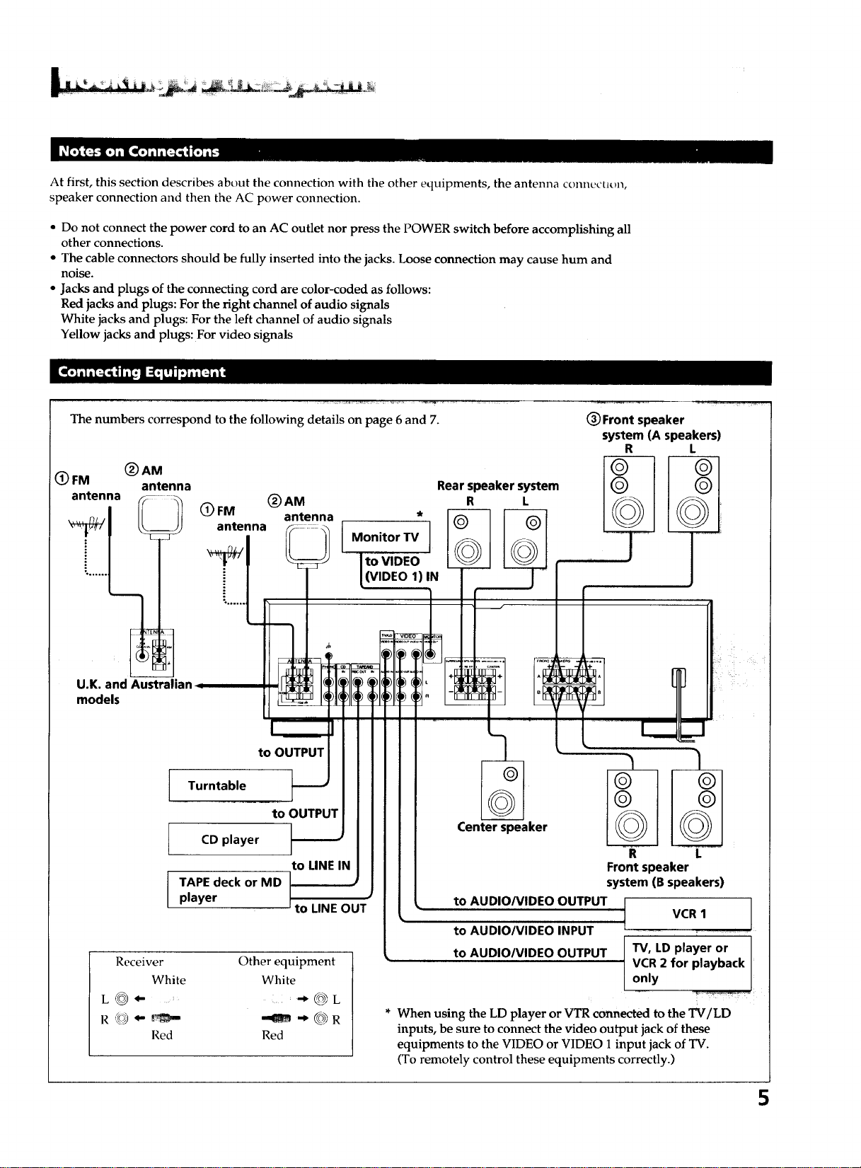
The numbers correspond to the following details on page 6 and 7.
(_ FM (_ AM
antenna
antenna
Rear speaker system
(_)AM R L
(_) FM antenna *
antenna Monitor TV
((VIDEO 1)IN
(_ Front speaker
system (A speakers)
R L
U.K. and Australb
models
to OUTPUT
Turntable
CD player
TAPE deck or MD
player
to OUTPUT
to LINE IN
to LINE OUT
Receiver
White
L_- ....
Red
Other equipment
White
@L
--am @R
Red
Center speaker
to AUDIO/VIDEO OUTPUT
to AUDIO/VIDEO INPUT
to AUDIO/VIDEO OUTPUT
R L
Front speaker
system (B speakers)
VCR 1 ]
T
TV, LD player or I
VCR 2 for playback I
only
/
* When using the LD player or VTR connected to the TV/LD
inputs, be sure to connect the video output jack of these
equipments to the VIDEO or VIDEO 1 input jack of TV.
(To remotely control these equipments correctly.)
5
Loading ...
Loading ...
Loading ...