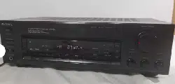

FM Stereo/FM-AM
Receiver
Operating Instructions
STR-D615
STR-D515
© 1994 by Sony Corporation
To prevent fire or shock hazard, do not
expose the unit to rain or moisture.
CAUTION: TO REDUCE THE HI5K OF ELECTRIC SHOCK,
DO NOT REMOVE COVER (OR BACK).
NO USER-SERVICEABLE PARTS INSIDE.
REFER SERVICING TO QUALIFIED SERVICE PERSONNEL.
This symbol is intended to alert the user to the
presence of uninsulated "dangerous voltage"
within the product's enclosure that may be of
sufficient magnitude to constitute
a risk of electric shock to persons.
This symbol is intended to alert the user to the
presence of important operating and
maintenance (servicing) instructions in the
literature accompanying the appliance.
Note to CATV system installer
This reminder is provided to call the CATV system
installer's attention to Article 820-40 of the NEC thatprovides
guidelines for proper grounding and, in
particular, specifies that the cable ground shall be
connected to the grounding system of the building, as
close to the point of cable entry as practical.
Owner's Record
The model number is located on the rear exterior and serial number
is on the rear. Record the serial number in the space provided
below. Refer to these numbers whenever you call upon your Sony
dealer regarding this product.
Model No. STR-D615 Serial No.
Model No. STR-D515 Serial No.
INFORMATION
This equipment has been tested and found to comply with the limits
for a Class B digital device, pursuant to Part 15 of the FCC Rules.
These limits are designed to provide reasonable protection against
harmful interference in a residential installation. This equipment
generates, uses, and can radiate radio frequency energy and, if not
installed and used in accordance with the instructions, may cause
harmful interference to radio communications. However, there is no
guarantee that interference will not occur in a particular installation.
If this equipment does cause harmful interference to radio or
television reception, which can be determined by turning the
equipment off and on, the user is encouraged to try to correct the
interference by one or more of the following measures:
--Reorient or relocate tile receiving antenna.
--Increase the separation between the equipment and Jc_c_vcJ.
--Connect the equipment into an outlet on a circuit different from
that to which the receiver is connected.
--Consult the dealer or an experienced radio/TV technician for
help.
CAUTION
You are cautioned that any change or modifications not expressly
approved in this manual could void your authority to operate this
equipment.
NOTICE FOR THE CUSTOMERS IN THE UNITED KINGDOM
A moulded plug complying with BS 1363 is fitted to this equipment
for your safety and convenience.
Should the fuse in the plug supplied need to be replaced, a 5
AMP fuse approved by ASTA or BSI to BS 1362, (i.e. marked with
<_ or _ mark) must be used.
If the plug supplied with this equipment has a detachable fuse
cover, be sure to attach the fuse cover after you change the fuse.
Never use the plug without the fuse cover. If you should lose the
fuse cover, please contact your nearest Sony service station.
IMPORTANT
If the plug supplied is not suitable for the socket outlets in your
home, it should be cut off and an appropriate plug fitted in
accordance with the following instructions.
The wires in this mains lead are coloured in accordance with the
following code:
Blue: Neutral
Brown: Live
As the colours of the wires in the mains lead of this apparatus
may not correspond with the coloured markings identifying the
terminals in your plug, proceed as follows:
The wire which is coloured blue must be connected to the
terminal which is marked with the letter N or coloured black.
The wire which is coloured brown must be connected to the
terminal which is marked with the letter L or coloured red. Do
not connect either wire to the earth terminal in the plug which is
marked by the letter E or by the safety earth symbol __d_or
coloured green or green and yellow.
WARNING
To prevent shock hazard, do not insert the plug cut off from the
mains lead into a socket outlet. This plug cannot be used and
should be destroyed.
For the customers in Canada
-- CAUTION :
TO PREVENT ELECTRIC SHOCK, DO NOT USE THIS
POLARIZED AC PLUG WITH AN EXTENSION CORD,
RECEPTACLE OR OTHER OUTLET UNLESS THE
BLADES CAN BE FULLY INSERTED TO PREVENT
BLADE EXPOSURE.
This apparatus complies with the Class Blimits for radio noise
emissions set out in Radio Interference Regulations.
2
Introduction
Introduction
Overview ....................................................................................... 3
Precautions ................................................................................... 4
Chapter 1 Getting Started
Unpacking .................................................................................... 4
Checking the supplied accessories ...................................... 4
Inserting the batteries into the remote commander ......... 4
Hooking up the system .............................................................. 5
Notes on connections ........................................................... 5
Connecting equipment ......................................................... 5
Connecting the FM antenna ................................................ 6
Connecting the antenna ground ......................................... 6
Connecting the AM antenna ................................................ 6
Connecting speaker systems ............................................... 7
Connecting the AC power (Except U.K. model) ............... 7
Chapter 2 Basic Operations
Listening to/watching a program source ................................ 8
Selecting a program source .................................................. 8
Selecting the speaker system ................................................ 8
Adjusting the audio ............................................................... 8
Receiving FM/AM broadcasts ................................................... 9
Tuning in a station directly Direct tuning ......................... 9
Automatic tuning .............................................................. 10
Presetting stations ............................................................... 10
Tuning in a preset station - Preset tuning ....................... 11
Remote controls .......................................................................... 12
Using the remote .................................................................. 12
Changing the settings of the FUNCTION buttons ......... 13
Chapter 3 Advanced Operations
Recording an audio source ...................................................... 14
Recording ............................................................................. 14
Recording a video source .......................................................... 14
Video tape editing ............................................................... 14
Obtaining the surround effect .................................................. 15
Available types of effects .................................................... 15
Selecting the surround mode ............................................. 15
Placement of speakers and selecting the
CENTER MODE for dolby surround sound ................ 16
Adjusting the speaker volume ........................................... 17
Adjusting the delay time of the rear speakers ................. 18
Chapter 4 Other Information
Troubleshooting guide .............................................................. 19
Specifications .............................................................................. 21
Identifying the parts and controls .......................................... 23
Front panel ............................................................................ 23
Remote commander ............................................. Back cover
The sri R--DO15/ D515 is an FM Stereo / I_M-AM receiver and
audio/video control center.
You can listen to various audio/video program sources with
this unit.
TV/video programs
• You can enjoy TV or CATV programs with FM simulcast.
Tuner
• Precise tuning is ensured by a quartz-locked digital
synthesizer.
Surround sound system
• This unit incorporates all of 3 types of surround effect.
13nlmur_m_*_l.. . .
DOLBY* PRO LOGIC ..... o_,€ • Thlsumt
incorporates the Dolby Pro Logic Surround
Decoder which has the same functions for playback as
movie theaters and gives a theater-like experience in your
listening room, naturally reproducing the audio sound
field.
The input balance of Dolby surround program sources is
automatically adjusted.
Since STR-D615 provides the high power center amplifier,
you can obtain the optimum center speaker output
according to the power of the front speakers system.
HALL: Surround provides reverberation effect that is
produced in a large concert hall.
SIMULATED: Surround gives the feeling of width and
thickness to monaural sound of old movie program, etc.
Manufactured under license from Dolby Laboratories Licensing
Corporation. Additionally licensed under one or more of the
following patents: U.S. number 3,959,590: Canadian numbers
1,004,603 and 1,037,877. "DOLBY", "Pro Logic", and the double-D
symbol are trademarks of Dolby Laboratories Licensing
Corporation.
Remote control
• The supplied remote commander allows you to remotely
control this unit and the equipments connected to the unit.
3
On safety
• For U.S.A. and Canadian models, operate the unit only on
120 V AC, 60 Hz.
• For U.K. model, operate the unit only on 240 V AC, 50/60
Hz.
• For Australian model, operate the unit only on 240 V AC,
50 Hz.
• Should any solid object or liquid fall into the cabinet,
unplug the unit and have it checked by qualified
personnel before operating it any further.
• Unplug the unit from the wall outlet if it is not to be used
for an extended period of time. To disconnect the cord,pull
it out by grasping the plug. Never pull the cord itself.
• One blade of the plug is wider than the other for the
purpose of safety and will fit into the power outlet only
one way. If you are unable to insert the plug fully into the
outlet, contact your dealer. (not applicable to U.K. and
Australian customers)
• AC power cord must be changed only at the qualified
service shop.
• This unit is not disconnected from the AC power source as
long as it is connected to the mains outlet, even if the unit
itself has been turned off.
On operation
Before making program source connections, be sure to
turn the power switch off and unplug the unit.
To prevent internal heat buildup in the unit,
place the unit in a location with adequate air circulation.
Do not install the unit:
• near heat sources such as radiators or air ducts.
• in a place subject to direct sunlight, excessive dust,
mechanical vibration or shock.
Do not place anything on top of the cabinet.
The top ventilation holes must be unobstructed for the
proper operation of the unit and to prolong the life of its
components.
On cleaning the cabinet
Clean the cabinet, panel and controls with a soft cloth lightly
moistened with mild detergent solution. Do not use any type
of abrasive pad, scouring powder, or solvent such as alcohol
or benzine.
For the customers in the U.S.A.
For detailed safety precautions, see the "IMPORTANT
SAFEGUARDS" leaflet.
If you have any question or problem concerning your unit,
please consult your nearest Sony dealer.
Do not throw away the carton and packing
material !
It will be an ideal container when transporting the system for
repair work, etc.
After unpacking, check that the following accessories are
present.
• FM wire antenna .................................................................... (1)
• AM loop antenna ................................................................... (1)
• Remote commander .............................................................. (1)
• Sony batteries SUM-3 (NS) ................................................... (2)
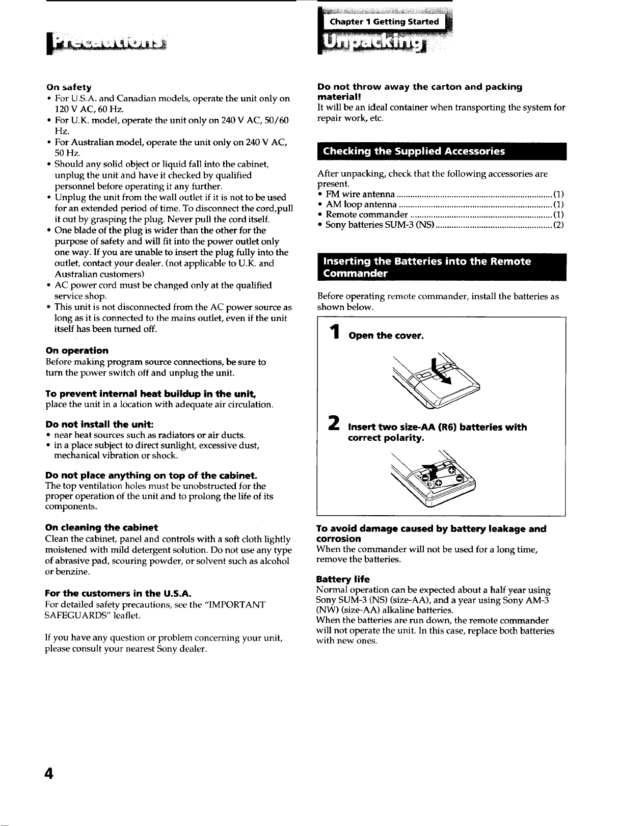
Before operating remote commander, install the batteries as
shown below.
Open the cover.
2
Insert two size-AA (R6) batteries with
correct polarity.
To avoid damage caused by battery leakage and
corrosion
When the commander will not be used for a long time,
remove the batteries.
Battery life
Normal operation can be expected about a half year using
Sony SUM-3 (NS) (size-AA), and a year using Sony AM-3
(NW) (size-AA) alkaline batteries.
When the batteries are run down, the remote commander
will not operate the unit. In this case, replace both batteries
with new ones.
4
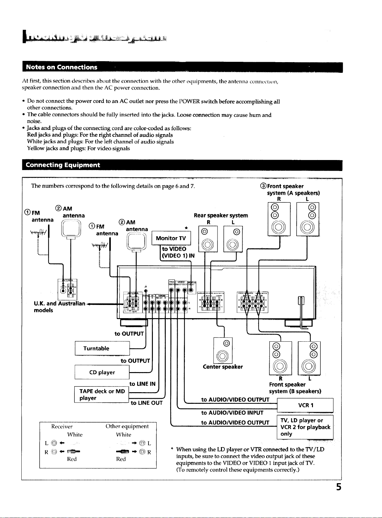
At first, this section describes about the connection with the other equipments, the antenna connectiun,
speaker connection and then the AC power connection.
• Do not connect the power cord to an AC outlet nor press the POWER switch before accomplishing all
other connections.
• The cable connectors should be fully inserted into the jacks. Loose connection may cause hum and
noise.
• Jacks and plugs of the connecting cord are color-coded as follows:
Red jacks and plugs: For the right channel of audio signals
White jacks and plugs: For the left channel of audio signals
Yellow jacks and plugs: For video signals
The numbers correspond to the following details on page 6 and 7.
(_ FM (_ AM
antenna
antenna
Rear speaker system
(_)AM R L
(_) FM antenna *
antenna Monitor TV
((VIDEO 1)IN
(_ Front speaker
system (A speakers)
R L
U.K. and Australb
models
to OUTPUT
Turntable
CD player
TAPE deck or MD
player
to OUTPUT
to LINE IN
to LINE OUT
Receiver
White
L_- ....
Red
Other equipment
White
@L
--am @R
Red
Center speaker
to AUDIO/VIDEO OUTPUT
to AUDIO/VIDEO INPUT
to AUDIO/VIDEO OUTPUT
R L
Front speaker
system (B speakers)
VCR 1 ]
T
TV, LD player or I
VCR 2 for playback I
only
/
* When using the LD player or VTR connected to the TV/LD
inputs, be sure to connect the video output jack of these
equipments to the VIDEO or VIDEO 1 input jack of TV.
(To remotely control these equipments correctly.)
5
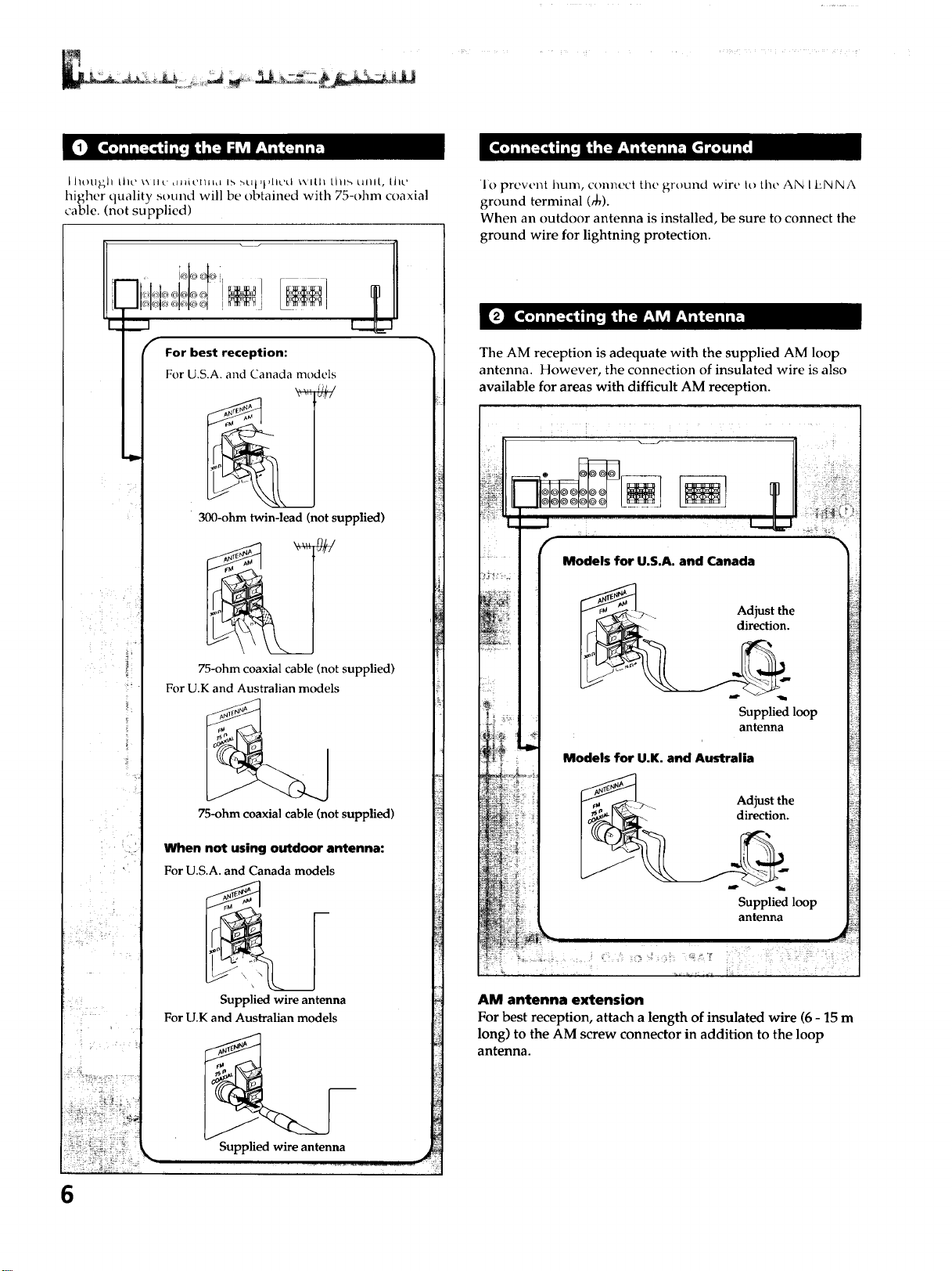
L J/ot]_h Lhc ',_.[I,_' _H_iCmnL lb :_Ut,l,lt,,.'d wIlll Lhl_, uml, Lhc
higher quality sound will be obtained with 75-ohm coaxial
cable. (not supplied)
For best reception:
For U.S.A. and Canada models
300-ohm twin-lead (not supplied)
75-ohm coaxial cable (not supplied)
For U.K and Australian models
75-ohm coaxial cable (not supplied)
When not using outdoor antenna:
For U.S.A. and Canada models
Supplied wire antenna
For U.K and Australian models
Supplied wire antenna
6
1o prevent hum, connect the ground wire It>the AN I ENNA
ground terminal (_0).
When an outdoor antenna is installed, be sure to connect the
ground wire for lightning protection.
The AM reception is adequate with the supplied AM loop
antenna. However, the connection of insulated wire is also
available for areas with difficult AM reception.
Models for U.S.A, and Canada
_> Adjust the
I_- direction.
Supplied loop
antenna
Models for U.K. and Australia
_. >.._ Adjust the
_ direction.
Supplied loop
antenna
AM antenna extension
For best reception, attach a length of insulated wire (6 - 15 m
long) to the AM screw connector in addition to the loop
antenna.
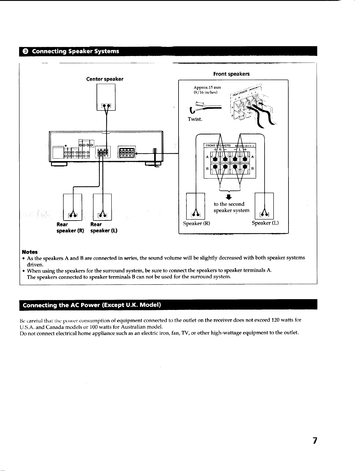
Center s)eaker
Rear Rear
speaker (R) speaker (L)
Front speakers
Approx.15 mm
(9/16 inches)
Twist.
Speaker (R)
to the second
speaker system
i
Speaker (L)
Notes
• As the speakers A and B are connected in series, the sound volume will be slightly decreased with both speaker systems
driven.
• When using the speakers for the surround system, be sure to connect the speakers to speaker terminals A.
The speakers connected to speaker terminals B can not be used for the surround system.
Be careiul that the power consumption of equipment connected to the outlet on the receiver does not exceed 120 watts for
U.S.A. and Canada models or 100 watts for Australian model.
Do not connect electrical home appliance such as an electric iron, fan, TV, or other high-wattage equipment to the outlet.
7
[POWER-_ONI 1
_--J / DDBB
o 't_- '-;''-_:i!_"-" "I'
I
L turntable]
I Op'ayerI
Tape deck or
MD player I 2
I VCR I
I TV/LD player I
@@@
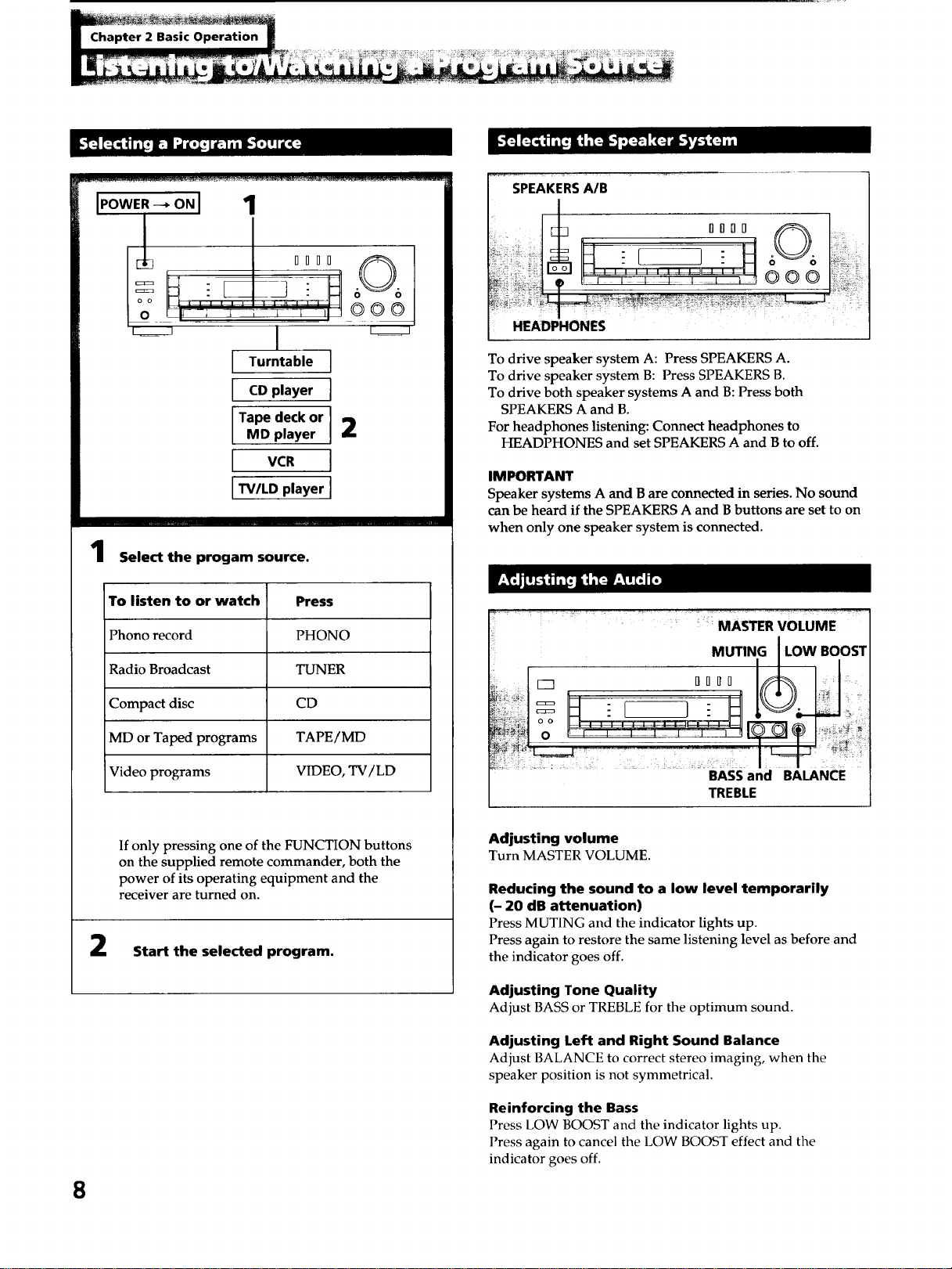
Select the progam source.
To listen to or watch Press
Phono record PHONO
Radio Broadcast TUNER
Compact disc CD
MD or Taped programs TAPE/MD
Video programs VIDEO, TV/LD
If only pressing one of the FUNCTION buttons
on the supplied remote commander, both the
power of its operating equipment and the
receiver are turned on.
Start the selected program.
8
SPEAKERSA/B
O00D 0 :
HEADPHONES
To drive speaker system A: Press SPEAKERS A.
To drive speaker system B: Press SPEAKERS B.
To drive both speaker systems A and B: Press both
SPEAKERS A and B.
For headphones listening: Connect headphones to
HEADPHONES and set SPEAKERS A and B to off.
IMPORTANT
Speaker systems A and B are connected in series. No sound
can be heard if the SPEAKERS A and B buttons are set to on
when only one speaker system is connected.
.... . > ...... ; :
: MASTER VOLUME
MUTING I LOW BOOST
M
oo , , -..............
BASS and BALANCE
TREBLE
Adjusting volume
Turn MASTER VOLUME.
Reducing the sound to a low level temporarily
(- 20 dB attenuation)
Press MUTING and the indicator lights up.
Press again to restore the same listening level as before and
the indicator goes off.
Adjusting Tone Quality
Adjust BASS or TREBLE for the optimum sound.
Adjusting Left and Right Sound Balance
Adjust BALANCE to correct stereo imaging, when the
speaker position is not symmetrical.
Reinforcing the Bass
Press LOW BOOST and the indicator lights up.
Press again to cancel the LOW BOOST effect and the
indicator goes off.
_ _ _ii__i:__i_i_i__i!i__i__i__I__!_
i i!lill i[_111 II _.._ _-_'_ [o] i11 I]I i{:_q _ k_- - I] Ii_qlil!lilli[,--
3
Select SPEAKERS A
and/or B.
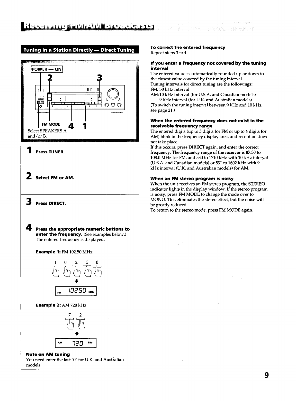
Press TUNER.
Select FM or AM.
Press DIRECT.
Press the appropriate numeric buttons to
enter the frequency. (Seeexamples below.)
The entered frequency is displayed.
Example 1: FM 102.50 MHz
1 0 2 5 0
Example 2: AM 720 kHz
7 2
4
Note on AM tuning
You need enter the last "0" for U.K. and Australian
models.
To correct the entered frequency
Repeat steps 3 to 4.
If you enter a frequency not covered by the tuning
interval
The entered value is automatically rounded up or down to
the closest value covered by the tuning interval.
Tuning intervals for direct tuning are the followings:
FM: 50 kHz interval
AM: 10 kHz interval (for U.S.A. and Canadian models)
9 kHz interval (for U.K. and Australian models)
(To switch the tuning interval between 9 kHz and 10 kHz,
see page 21.)
When the entered frequency does not exist in the
receivable frequency range
The entered digits (up to 5 digits for FM or up to 4 digits for
AM) blink in the frequency display area, and reception does
not take place.
If this occurs, press DIRECT again, and enter the correct
frequency. The frequency range of the receiver is 87.50 to
108.0 MHz for FM, and 530 to 1710 kHz with 10 kHz intery, al
(U.S.A. and Canadian models) or 531 to 1602 kHz with 9
kHz interval (U.K. and Australian models) for AM.
When an FM stereo program is noisy
When the unit receives an FM stereo program, the STEREO
indicator lights in the display window. If the stereo program
is noisy, press FM MODE to change the mode over to
MONO. This eliminates the stereo effect, but the noise will
be greatly reduced.
To return to the stereo mode, press FM MODE again.
9
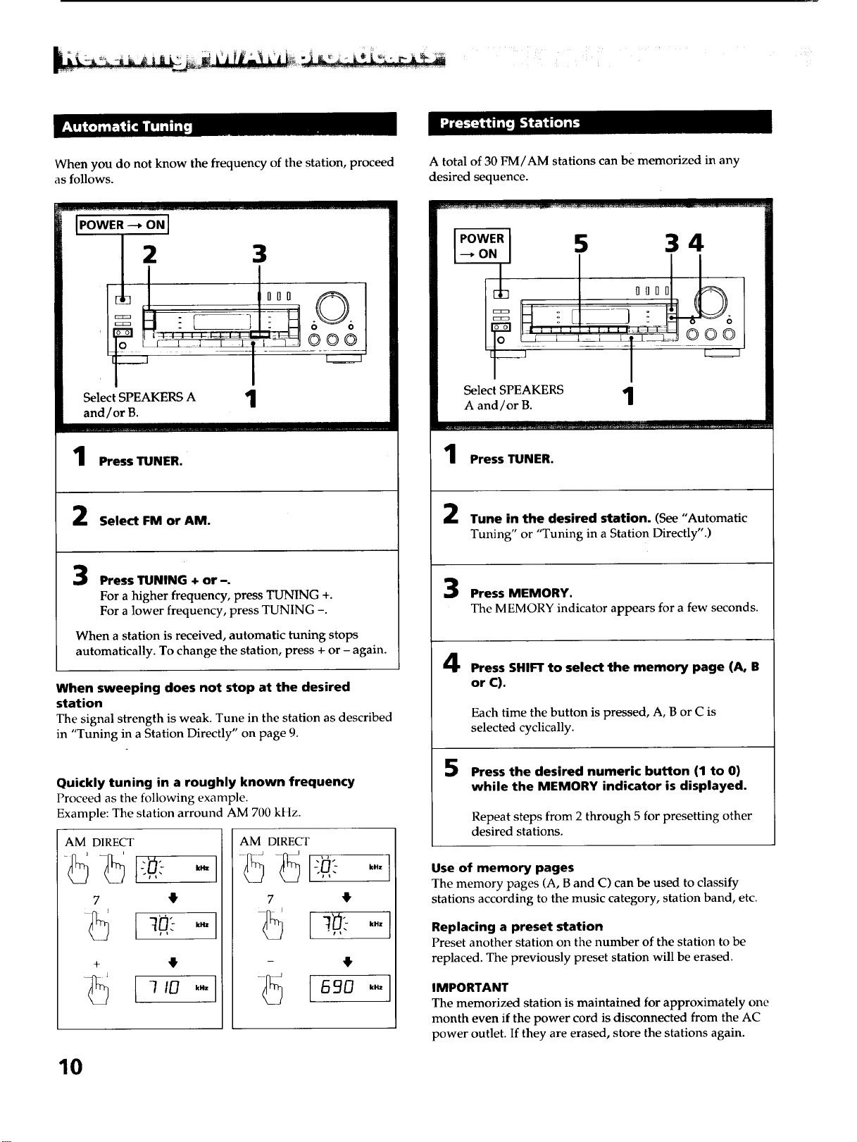
When you do not know the frequency of the station, proceed
as follows.
IPOWER --_ ON I
Select SPEAKERS A 1
and/or B.
oo©
Press TUNER.
Select FM or AM.
Press TUNING + or -.
For a higher frequency, press TUNING +.
For a lower frequency, press TUNING -.
When a station is received, automatic tuning stops
automatically. To change the station, press + or - again.
When sweeping does not stop at the desired
station
The signal strength is weak. Tune in the station as described
in "Tuning in a Station Directly" on page 9.
Quickly tuning in a roughly known frequency
Proceed as the following example.
Example: The station arround AM 700 kHz.
AM DIRECT AM DIRECT
7 4
+
7 4
kHz
kHz
A total of 30 FM/AM stations can be memorized in any
desired sequence.
IPOWERI _ 3 4
--ON, T i i
Select SPEAKERS 1
A and/or B.
Press TUNER.
Tune in the desired station. (See "Automatic
Tuning" or "Tuning in a Station Directly".)
Press MEMORY.
The MEMORY indicator appears for a few seconds.
Press SHIFT to select the memory page (A, B
or C).
Each time the button is pressed, A, B or C is
selected cyclically.
5
Press the desired numeric button (1 to 0)
while the MEMORY indicator is displayed.
Repeat steps from 2 through 5 for presetting other
desired stations.
Use of memory pages
The memory pages (A, B and C) can be used to classify
stations according to the music category, station band, etc.
Replacing a preset station
Preset another station on the number of the station to be
replaced. The previously preset station will be erased.
IMPORTANT
The memorized station is maintained for approximately one
month even if the power cord is disconnected from the AC
power outlet. If they are erased, store the stations again.
10
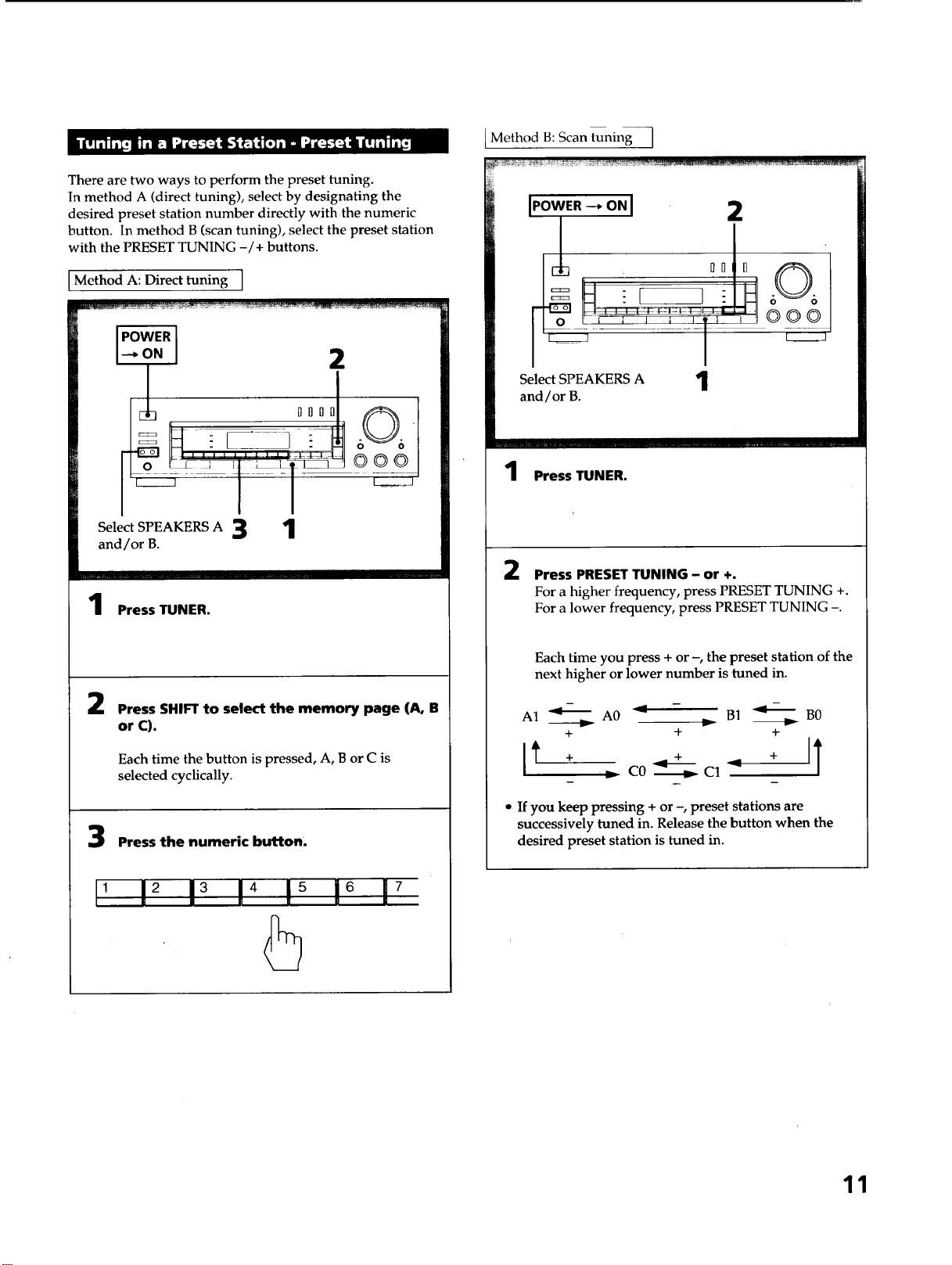
There are two ways to perform the preset tuning.
In method A (direct tuning), select by designating the
desired preset station number directly with the numeric
button. In method B (scan tuning), select the preset station
with the PRESET TUNING -/+ buttons.
Method A: Direct tuning ]
2
°°°J
Select SPEAKERS A 3 1
and/or B.
OOO
Press TUNER.
2
Press SHIFTto select the memory page (A, B
or C).
Each time the button is pressed, A, B or C is
selected cyclically.
Press the numeric button.
, 12 13 14 !_ 16 17
Method B: Scan tuning I
I.owE._o.I 2
l
O0 0 606
o i 1 _ _ '1' ' 000
Select SPEAKERS A '1
and/or B.
I
1 Press TUNER.
2 Press PRESET TUNING- or +.
For a higher frequency, press PRESET TUNING +.
For a lower frequency, press PRESET TUNING -.
Each time you press + or -, the preset station of the
next higher or lower number is tuned in.
A1 _ A0 _ - B1 _ B0
+ + +
_ C0 _ C1 _
• If youkeep pressing + or -, preset stations are
successively tuned in. Release the button when the
desired preset station is tuned in.
11
The remote lets you operate the connected components as
well as the receiver. Press one of the FUNCTION buttons
first to select the program source, then use the following
buttons to operate each component.
The FUNCTION buttons are factory set in the following list.
FUNCTION to be Operating equipment
pressed
TUNER Tuner
TAPE/MD Tape deck
CD CD player
TV/LD TV
VIDEO VCR (VTR 1 mode)
PHONO (The receiver enters the PHONO mode)
This remote commander can control Sony stereo cassette
deck having RMS function.
For more information on the availability of Sony stereo
cassette deck with RMS capability, contact your nearest Sony
dealer.
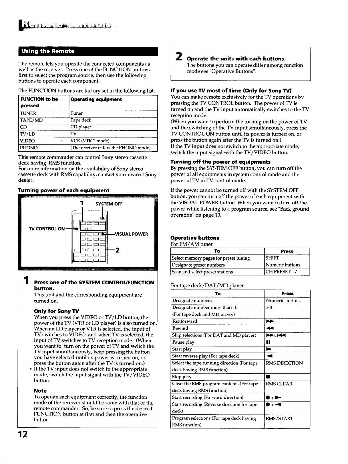
Turning power of each equipment
W CONTROL ON --
1
Press one of the SYSTEM CONTROL/FUNCTION
button.
This unit and the corresponding equipment are
turned on.
Only for Sony lrv
When you press the VIDEO or TV/LD button, the
power of the TV (VTR or LD player) is also turned on
When an LD player or VTR is selected, the input of
TV switches to VIDEO, and when TV is selected, the
input of TV switches to TV reception mode. (When
you want to turn on the power of TV and switch the
TV input simultaneously, keep pressing the button
you have selected until its power is turned on, or
press the button again after the TV is turned on.)
If the TV input does not switch to the appropriate
mode, switch the input signal with the TV/VIDEO
button.
Note
To operate each equipment correctly, the function
mode of the receiver should be same with that of the
remote commander. So, be sure to press the desired
FUNCTION button at first and then the operative
button.
12
2
Operate the units with each buttons.
The buttons you can operate differ among function
mode see "Operative Buttons".
If you use TV most of time (Only for Sony TV)
You can make remote exclusively for the TV operations by
pressing the TV CONTROL button. The power of TV is
turned on and the TV input automatically switches to the TV
reception mode.
(When you want to perform the turning on the power of TV
and the switching of the TV input simultaneously, press the
TV CONTROL ON button until its power is turned on, or
press the button again after the TV is turned on.)
If the TV input does not switch to the appropriate mode,
switch the input signal with the TV/VIDEO button.
Turning off the power of equipments
By pressing the SYSTEM OFF button, you can turn off the
power of all equipments in system control mode and the
power of TV in TV control mode.
If the power cannot be turned off with the SYSTEM OFF
button, you can turn off the power of each equipment with
the VISUAL POWER button. When you want to turn off the
power while listening to a program source, see "Back ground
operation" on page 13.
Operative buttons
For FM/AM tuner
To Press
Select memory pages for preset tuning SHIFT
Designate preset numbers Numeric buttons
Scan and select preset stations CH PRESET +/-
For tape deck/DAT/MD player
To Press
Designate numbers Numeric buttons
Designate number more than 10 >10
(For tape deck and MD player)
Fastforward
Rewind _b9
Skip selections (For DAT and MD player) _ID4,
Pause play I I
Start play
Start reverse play (For tape deck) "91
Select the tape running direction (For tape RMS DIRECTION
deck having RMS function)
Stop play •
Clear the RMS program contents (For tape RMS CLEAR
deck having RMS function)
Start recording (Forward direction) • +
Start recording (Reverse direction for tape • + -'9
deck)
Program selections (For tape deck having RMS/START
RMS function)
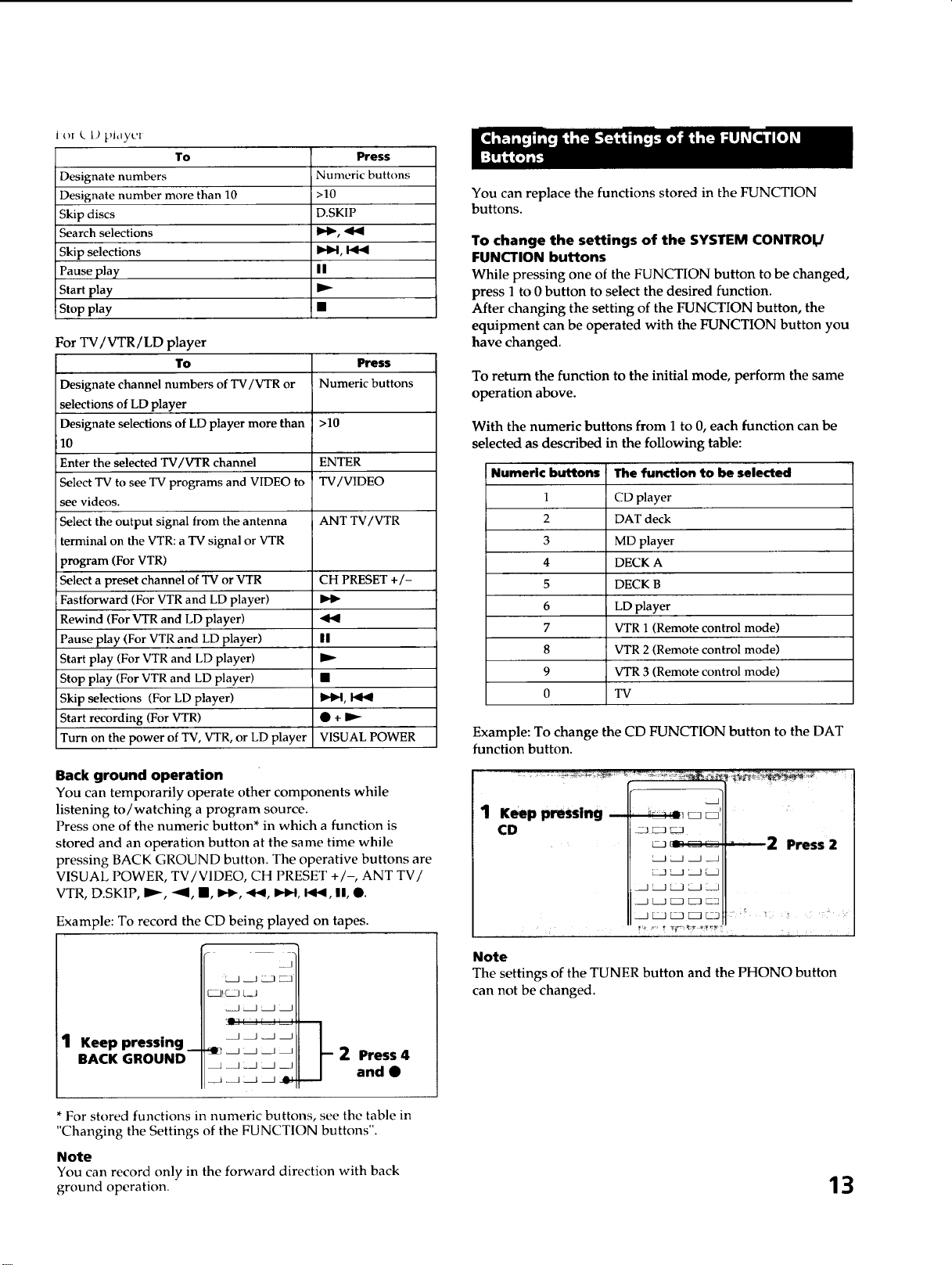
Jo[ k L) pJdyl'[
To
Designate numbers
Designate number more than 10
Skip discs
Search selections
Skip selections
Pause play
Start play
Stop play
Press
Numeric buttons
>10
D.SKIP
I_1, I_1_
||
For TV/VTR/LD player
To
Designate channel numbers of TV/VTR or
selections of LD player
Designate selections of LD player more than
10
Enter the selected TV/VTR channel
Select TV to see TV programs and VIDEO to
see videos.
Select the output signal from the antenna
terminal on the VTR: a TV signal or VTR
program (For VTR)
Select a preset channel of TV or VTR
Fastforward (For VTR and LD player)
Rewind (For VTR and LD player)
Pause play (For VTR and LD player)
Start play (For VTR and LD player)
Stop play (For VTR and LD player)
Skip selections (For LD player)
Start recording (For VTR)
Turn on the power of TV, VTR, or LD player
Press
Numeric buttons
>10
ENTER
TV/VIDEO
ANT TV/VTR
CH PRESET +/-
I!
_D,q, blb_
@ + D,,_
VISUAL POWER
Back ground operation
You can temporarily operate other components while
listening to/watching a program source.
Press one of the numeric button* in which a function is
stored and an operation button at the same time while
pressing BACK GROUND button. The operative buttons are
VISUAL POWER, TV/V1DEO, CH PRESET +/-, ANT TV/
VTR, D.SKIP, IP--, "41, I, I..1_,.ql_, I_.-I, I_1_, I!, @.
Example: To record the CD being played on tapes.
1 Keep pressing _
BACK GROUND
_,_
__--2 Press 4
and •
* For stored functions in numeric buttons, see the table in
"Changing the Settings of the FUNCTION buttons".
Note
You can record only in the forward direction with back
ground operation.
You can replace the functions stored in the FUNCTION
buttons.
To change the settings of the SYSTEM CONTROI_
FUNCTION buttons
While pressing one of the FUNCTION button to be changed,
press 1 to 0 button to select the desired function.
After changing the setting of the FUNCTION button, the
equipment can be operated with the FUNCTION button you
have changed.
To return the function to the initial mode, perform the same
operation above.
With the numeric buttons from I to 0, each function can be
selected as described in the following table:
Numeric buttons The function to be selected
1 CD player
2 DAT deck
3 MD player
4 DECK A
5 DECK B
6 LD player
7 VTR 1 (Remote control mode)
8 VTR 2 (Remote control mode)
9 VTR 3 (Remote control mode)
0 TV
Example: To change the CD FUNCTION button to the DAT
function button.
1 Keep pressing
CD
2 Press 2
Note
The settings of the TUNER button and the PHONO button
can not be changed.
13
Chpater 3 Advanced Operations
1
to TAPE / MD
OUT
2 l Tape deck or
MD player
1010 60 6
[ Turntable J
[ Tuner ]
t CDplayer J3
I vc. t
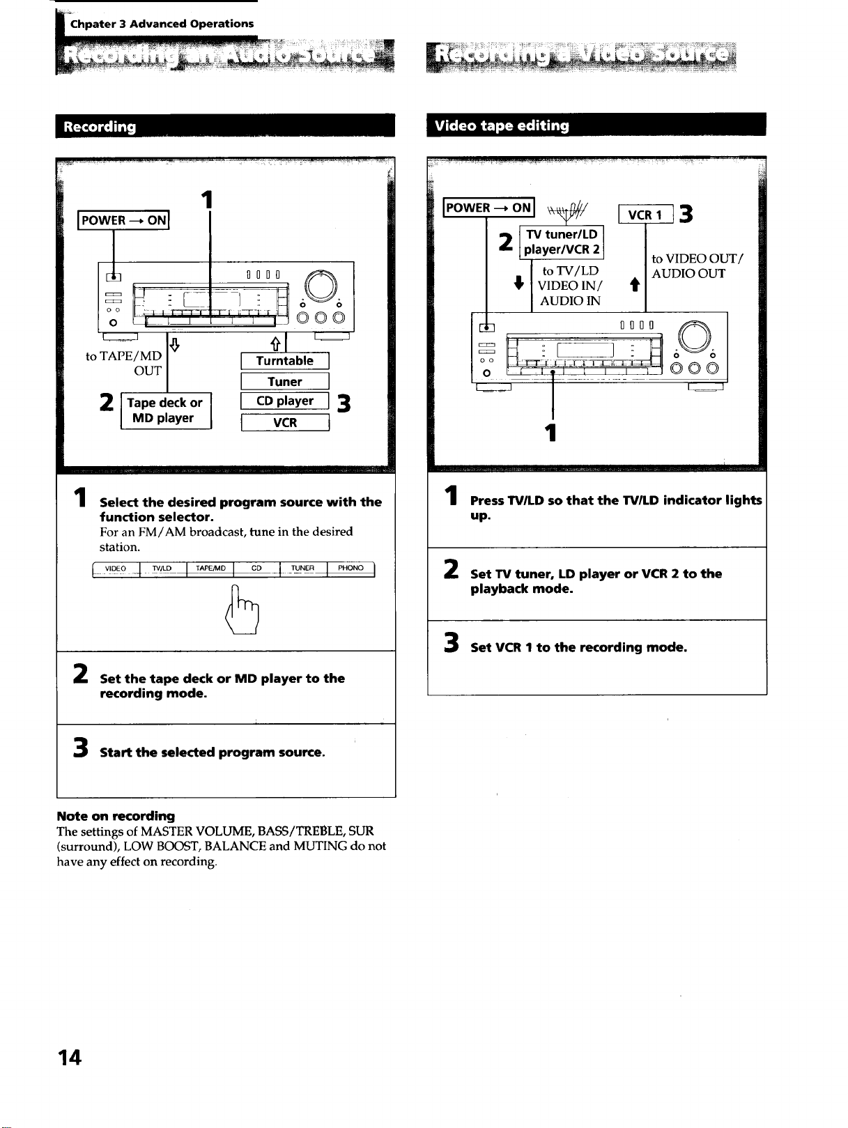
1
Select the desired program source with the
function selector.
For an FM/AM broadcast, tune in the desired
station.
l _,D_o-4_° I _° I °° -1-_°_ I _"°"°I
5
Set the tape deck or MD player to the
recording mode.
Start the selected program source.
2 [TV tuner/LD
player/VCR 2
to TV/LD
_' VIDEO IN/
AUDIO IN
[]_ IIOI
o o ;2--[_t ._:I ]Ei[TL
1
I_._Tl 3
to VIDEO Ot
AUDIO OUT
it
@00
....1 .... I ..... i
Press TVILD so that the TV/LD indicator lights
up.
Set TV tuner, LD player or VCR 2 to the
playback mode.
Set VCR I to the recording mode.
Note on recording
The settings of MASTER VOLUME, BASS/TREBLE, SUR
(surround), LOW BOOST, BALANCE and MUTING do not
have any effect on recording.
14
You can add 3 types ol surround ettects to tile soltware. 1o
enjoy the surround effects, two front and two rear speakers
are necessary.
In the Dolby mode, the speaker operation mode can be
selected according to your speaker configuration.
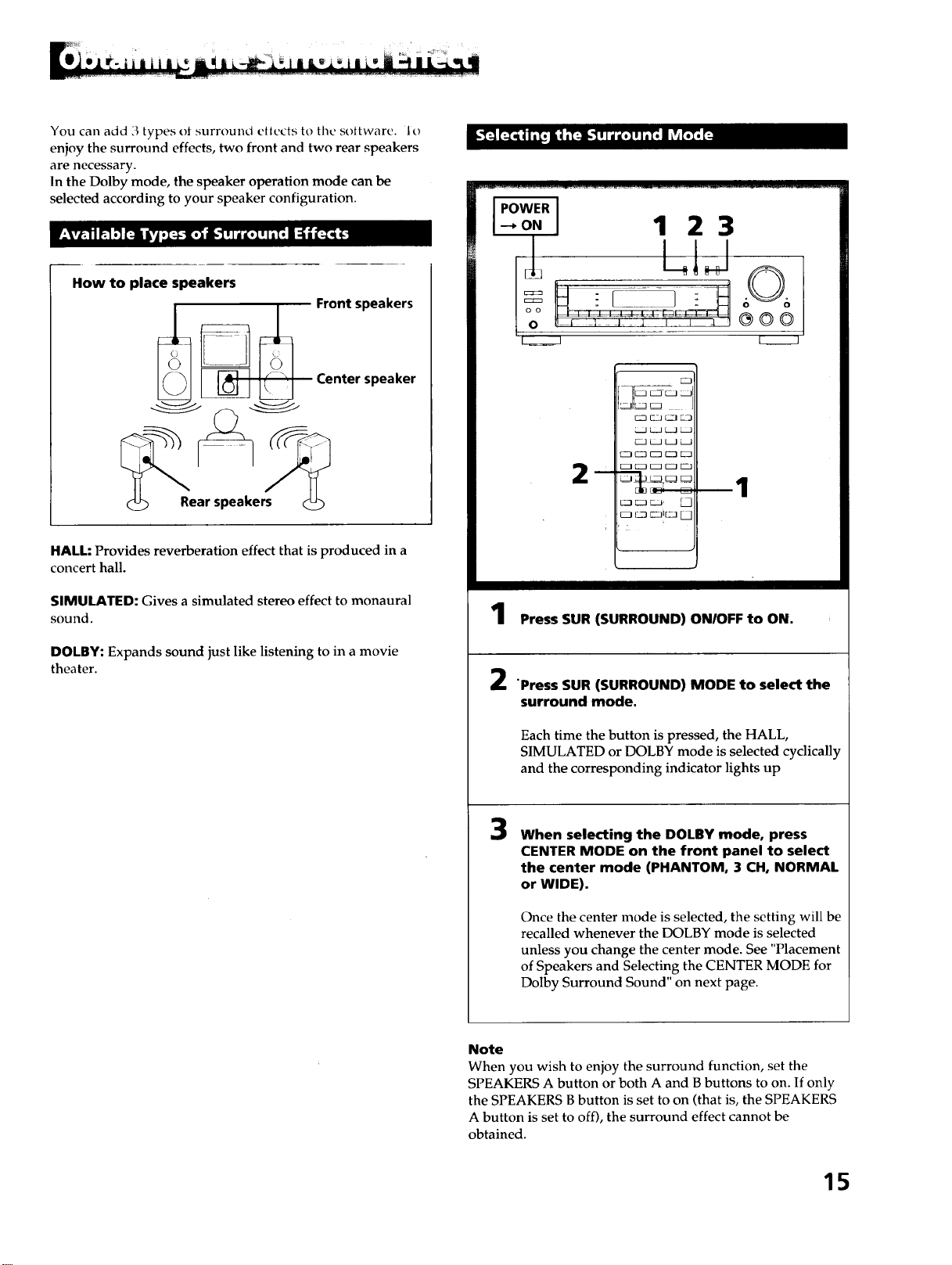
How to place speakers
Rear speakers
Front speakers
Center speaker
HALL: Provides reverberation effect that is produced in a
concert hall.
SIMULATED: Gives a simulated stereo effect to monaural
sound.
DOLBY: Expands sound just like listening to in a movie
theater.
IPOWERI
4o.I 1 23
k_J
m
3IE=J
rZ ' J
_!. _
2
1
Press SUR (SURROUND) ON/OFF to ON.
"Press SUR (SURROUND) MODE to select the
surround mode.
Each time the button is pressed, the HALL,
SIMULATED or DOLBY mode is selected cyclically
and the corresponding indicator lights up
3
When selecting the DOLBY mode, press
CENTER MODE on the front panel to select
the center mode (PHANTOM, 3 CH, NORMAL
or WIDE).
Once the center mode is selected, the setting will be
recalled whenever the DOLBY mode is selected
unless you change the center mode. See "Placement
of Speakers and Selecting the CENTER MODE for
Dolby Surround Sound" on next page.
Note
When you wish to enjoy the surround function, set the
SPEAKERS A button or both A and B buttons to on. If only
the SPEAKERS B button is set to on (that is, the SPEAKERS
A button is set to off), the surround effect cannot be
obtained.
15
_;,_ii ¸¸_I_ ,L L_
The Dolby Pro Logic Surround Decoder has the same
functions for playback as movie theaters and gives a theater-
like experience in your listening room, naturally reproducing
the audio sound field.
The STR-D615 and STR-D515 incorporate a decoder which
reproduces the specially encoded surround sound of Dolby
surround video programs.
In the Dolby surround mode, select the speaker operation
mode according to your speaker configuration by pressing
the CENTER MODE button. Each time the CENTER MODE
button is pressed, the mode and the display are changed in
the following order:
[-_ PHANTOM _ 3 CH _ NORMAL _ WIDE--
CENTER MODE button
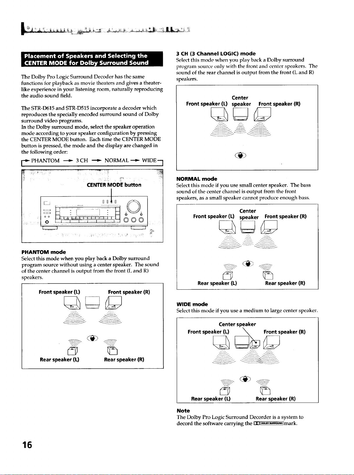
PHANTOM mode
Select this mode when you play back a Dolby surround
program source without using a center speaker. The sound
of the center channel is output from the front (L and R)
speakers.
Front speaker (L) Front speaker (R)
Rear speaker (L) Rear speaker (R)
3 CH (3 Channel LOGIC) mode
Select this mode when you play back a Dolby surround
program source only with the front and center speakers. The
sound of the rear channel is output from the front (L and R)
speakers.
Center
Front speaker (L) speaker Front speaker (R)
NORMAL mode
Select this mode if you use small center speaker. The bass
sound of the center channel is output from the front
speakers, as a small speaker cannot produce enough bass.
Center
Front speaker (L) speaker Front speaker (R)
Rear speaker (L) Rear speaker (R)
WIDE mode
Select this mode if you use a medium to large center speaker.
Center speaker
Front speaker (L) _ Front speaker (R)
Rear speaker (L) Rear speaker (R)
Note
The Dolby Pro Logic Surround Decorder is a system to
decord the software carrying the DDl._-,M'_-olmark.
16
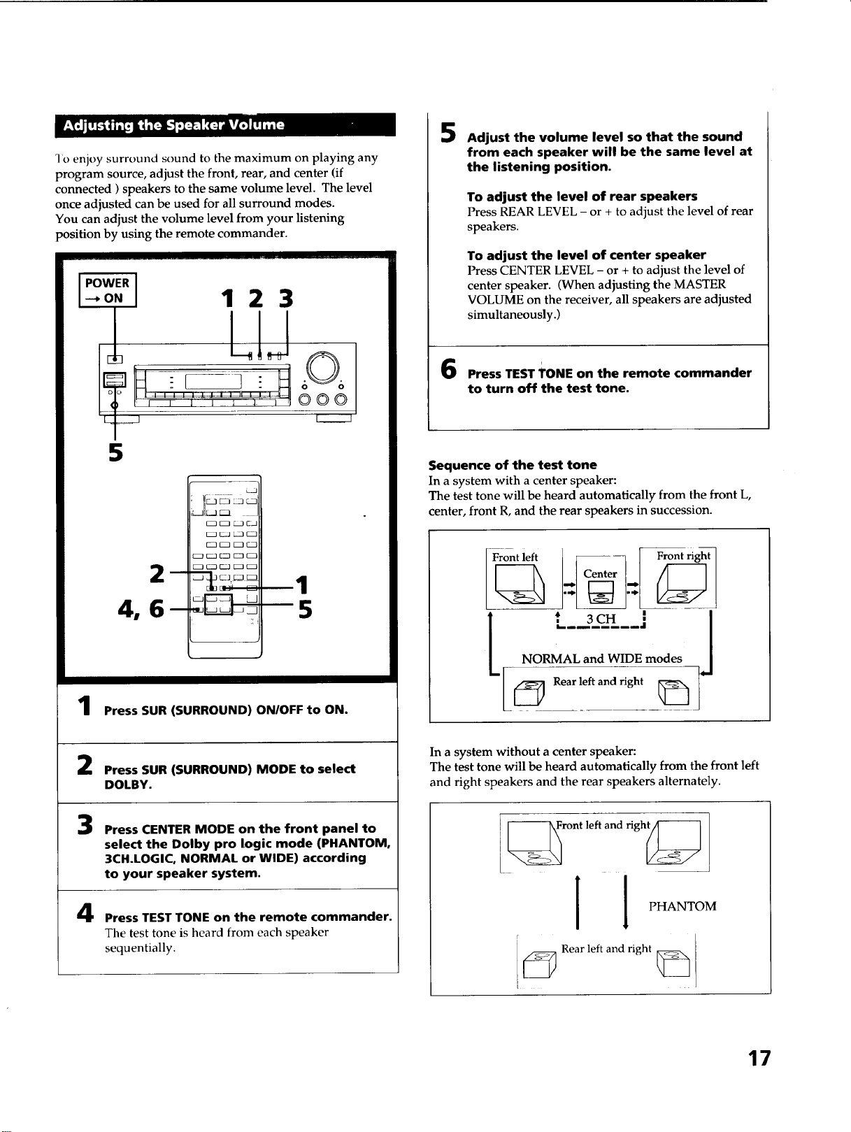
I'o enjoy surround sound to the maximum on playing any
program source, adjust the front, rear, and center (if
connected ) speakers to the same volume level. The level
once adjusted can be used for all surround modes.
You can adjust the volume level from your listening
position by using the remote commander.
WER
o. 123
I LIJ
5
Press SUR (SURROUND) ON/OFF to ON.
Press SUR (SURROUND) MODE to select
DOLBY.
3
4
Press CENTER MODE on the front panel to
select the Dolby pro logic mode (PHANTOM,
3CH.LOGIC, NORMAL or WIDE) according
to your speaker system.
Press TEST TONE on the remote commander.
The test tone is heard from each speaker
sequentially.
5
Adjust the volume level so that the sound
from each speaker will be the same level at
the listening position.
To adjust the level of rear speakers
Press REAR LEVEL - or + to adjust the level of rear
speakers.
To adjust the level of center speaker
Press CENTER LEVEL - or + to adjust the level of
center speaker. (When adjusting the MASTER
VOLUME on the receiver, all speakers are adjusted
simultaneously.)
i
Press TEST TONE on the remote commander
to turn off the test tone.
Sequence of the test tone
In a system with a center speaker:
The test tone will be heard automatically from the front L,
center, front R, and the rear speakers in succession.
. --L''Center''ri ,t
t L3,-Jj
NORMAL and WIDE modes
In a system without a center speaker:
The test tone will be heard automatically from the front left
and right speakers and the rear speakers alternately.
] _ront left and righ_
! PHANTOM
F
j _ Rear left and right _
17
)WER I
.o.I 1 2
':"hlJ
I
3
OOO
__i:1[
k
1
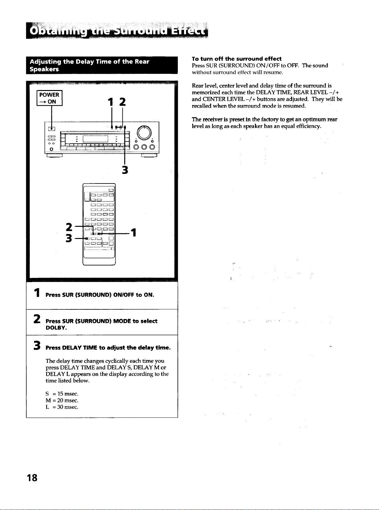
Press SUR (SURROUND) ON/OFF to ON.
Press SUR (SURROUND) MODE to select
DOLBY.
3
Press DELAY TIME to adjust the delay time.
The delay time changes cyclically each time you
press DELAY TIME and DELAY S, DELAY M or
DELAY L appears on the display according to the
time listed below.
S = 15 msec.
M = 20 msec.
L = 30 msec.
To turn off the surround effect
Press SUR (SURROUND) ON/OFF to OFF. The sound
without surround effect will resume.
Rear level, center level and delay time of the surround is
memorized each time the DELAY TIME, REAR LEVEL -/+
and CENTER LEVEL -/+ buttons are adjusted. They will be
recalled when the surround mode is resumed.
The receiver is preset in the factory to get an optimum rear
level as long as each speaker has an equal efficiency.
,p
18
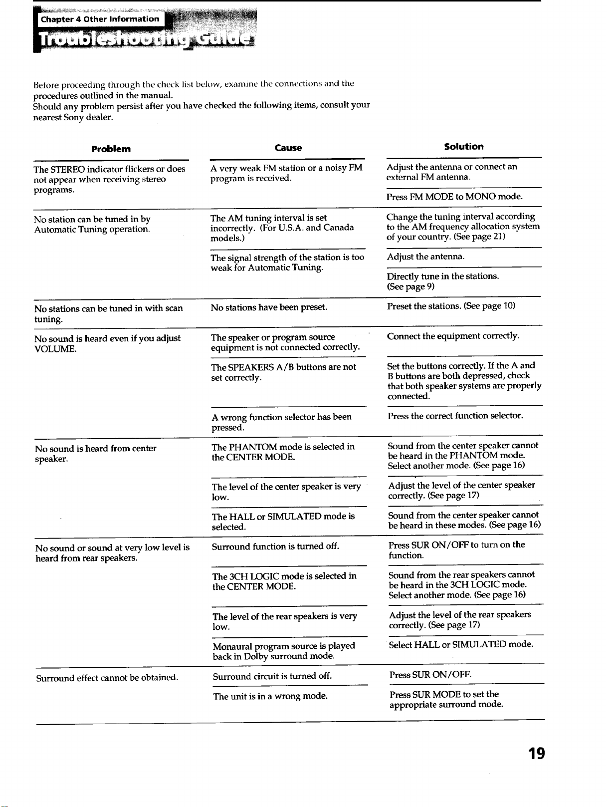
Before proceeding through the check list below, examine tile connections and the
procedures outlined in the manual.
Should any problem persist after you have checked the following items, consult your
nearest Sony dealer.
Problem Cause
Solution
Adjust the antenna or connect an
external FM antenna.
Press FM MODE to MONO mode.
The STEREO indicator flickers or does
not appear when receiving stereo
programs.
A very weak FM station or a noisy FM
program is received.
No station can be tuned in by
Automatic Tuning operation.
The AM tuning interval is set
incorrectly. (For U.S.A. and Canada
models.)
Change the tuning interval according
to the AM frequency allocation system
of your country. (See page 21)
The signal strength of the station is too
weak for Automatic Tuning.
Adjust the antenna.
Directly tune in the stations.
(See page 9)
No stations can be tuned in with scan No stations have been preset. Preset the stations. (See page 10)
tuning.
No sound is heard even if you adjust The speaker or program source Connect the equipment correctly.
VOLUME. equipment is not connected correctly.
The SPEAKERS A/B buttons are not
set correctly.
Set the buttons correctly. If the A and
B buttons are both depressed, check
that both speaker systems are properly
connected.
A wrong function selector has been
pressed.
Press the correct function selector.
No sound is heard from center
speaker.
The PHANTOM mode is selected in
the CENTER MODE.
Sound from the center speaker cannot
be heard in the PHANTOM mode.
Select another mode. (See page 16)
The level of the center speaker is very
lOW.
Adjust the level of the center speaker
correctly. (See page 17)
The HALL or SIMULATED mode is
selected.
Sound from the center speaker cannot
be heard in these modes. (See page 16)
No sound or sound at very low level is
heard from rear speakers.
Surround function is turned off.
The 3CH LOGIC mode is selected in
the CENTER MODE.
Press SUR ON/OFF to turn on the
function.
Sound from the rear speakers cannot
be heard in the 3CH LOGIC mode.
Select another mode. (See page 16)
The level of the rear speakers is very
low.
Adjust the level of the rear speakers
correctly. (See page 17)
Select HALL or SIMULATED mode.
Surround effect cannot be obtained.
Monaural program source is played
back in Dolby surround mode.
Surround circuit is turned off.
The unit is in a wrong mode.
Press SUR ON/OFF.
Press SUR MODE to set the
appropriate surround mode.
19
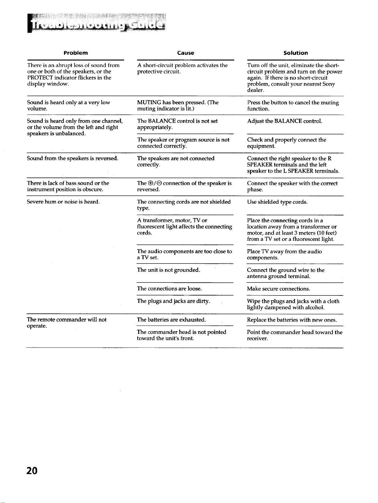
Problem Cause Solution
There is an abrupt loss of sound from
one or both of the speakers, or the
PROTECT indicator flickers in the
display window.
A short-circuit problem activates the
protective circuit.
Turn off the unit, eliminate the short-
circuit problem and turn on the power
again. If there is no short-circuit
problem, consult your nearest Sony
dealer.
Sound is heard only at a very low MUTING has been pressed. (The Press the button to cancel the muting
volume, muting indicator is lit.) function.
Sound is heard only from one channel, The BALANCE control is not set Adjust the BALANCE control.
or the volume from the left and right appropriately.
speakers is unbalanced.
The speaker or program source is not
connected correctly.
Check and properly connect the
equipment.
Sound from the speakers is reversed. The speakers are not connected Connect the right speaker to the R
correctly. SPEAKER terminals and the left
speaker to the L SPEAKER terminals.
There is lack of bass sound or the The (_/e connection of the speaker is Connect the speaker with the correct
instrument position is obscure, reversed, phase.
Severe hum or noise is heard. The connecting cords are not shielded Use shielded type cords.
type.
A transformer, motor, TV or
fluorescent light affects the connecting
cords.
The audio components are too close to
a TV set.
The unit is not grounded.
The connections are loose.
The plugs and jacks are dirty.
Place the connecting cords in a
location away from a transformer or
motor, and at least 3 meters (10 feet)
from a TV set or a fluorescent light.
Place TV away from the audio
components.
Connect the ground wire to the
antenna ground terminal.
Make secure connections.
Wipe the plugs and jacks with a cloth
lightly dampened with alcohol.
The remote commander will not
operate.
The batteries are exhausted.
The commander head is not pointed
toward the unit's front.
Replace the batteries with new ones.
Point the commander head toward the
receiver.
2O
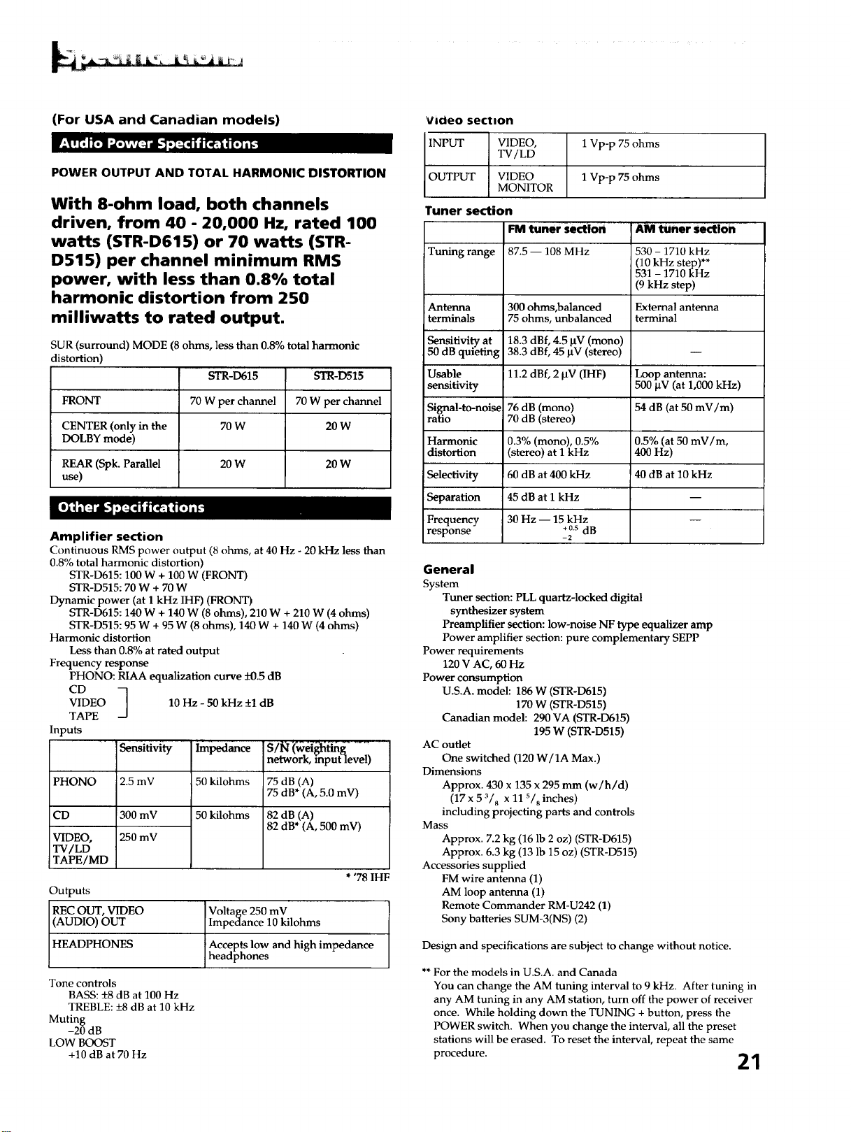
(For USA and Canadian models)
POWER OUTPUT AND TOTAL HARMONIC DISTORTION
With 8-ohm load, both channels
driven, from 40 - 20,000 Hz, rated 100
watts (STR-D615) or 70 watts (STR-
D515) per channel minimum RMS
power, with less than 0.8% total
harmonic distortion from 250
milliwatts to rated output.
SUR (surround) MODE (8 ohms, less than 0.8% total harmonic
distortion)
STR-D615 'STR-D515
FRONT 70 W per channel 70 W per channel
CENTER (only in the 70 W 20 W
DOLBY mode)
REAR (Spk. Parallel 20 W 20 W
use)
Amplifier section
Continuous RMS power output (8 ohms, at 40 Hz - 20 kHz less than
0.8% total harmonic distortion)
STR-D615:100 W + 100 W (FRONT)
STR-D515:70 W + 70 W
Dynamic power (at 1 kHz IHF) (FRONT)
STR-D615:140 W + 140 W (8 ohms), 210 W + 210 W (4 ohms)
STR-D515:95 W + 95 W (8 ohms), 140 W + 140 W (4 ohms)
Harmonic distortion
Less than 0.8% at rated output
Frequency response
PHONO: RIAA equalization curve -+0.5 dB
CD
VIDEO
TAPE
Inputs
PHONO
CD
VIDEO,
TV/LD
TAPE/MD
10 - 50 kHz +1 dB
Hz
' Sensitivity "Impedance
2.5 mV 50 kilohms
300 mV 50 kilohms
250 mV
network, input level)
75 dB (A)
75 dB* (A, 5.0 mV)
82 dB (A)
82 dB* (A, 500 mV)
* '78 IHF
Outputs
REC OUT, VIDEO Voltage 250 mV
(AUDIO) OUT Impedance 10 kilohms
HEADPHONES Aece pts low and high impedance
headphones
Tone controls
BASS: _+8dB at 100 Hz
TREBLE: +8 dB at 10 kHz
Muting
-20 dB
LOW BOOST
+10 dB at 70 Hz
Vicieo section
INPUT VIDEO, 1 Vp-p 75 ohms
TV/LD
OUTPUT VIDEO 1 Vp-p 75 ohms
MONITOR
Tuner section
FM tuner section AM tuner se(tlon
Tuning range 87.5 -- 108 MHz 530 - 1710 kHz
(10 kHz step)**
531 - 1710 kHz
(9 kHz step)
Antenna 300 ohms,balanced External antenna
terminals 75 ohms, unbalanced terminal
Sensitivity at 18.3 dBf, 4.5 BV (mono)
50 dB quieting 38.3 dBf, 45 _tV (stereo)
Usable 11.2 dBf, 2 ktV (IHF) !Loop antenna:
sensitivity 500 _tV (at 1,000 kHz)
Signal-to-noise 76 dB (mono) 54 dB (at 50 mV/m)
ratio 70 dB (stereo)
Harmonic 0.3% (mono), 0.5% 0.5% (at 50 mV/m,
distortion (stereo) at 1 kHz 400 Hz)
Selectivity 60 dB at 400 kHz 40 dB at 10 kHz
Separation 45 dB at 1 kHz
Frequency 30 Hz -- 15 kHz
+0.s dB
response - 2
General
System
Tuner section: PLL quartz-locked digital
synthesizer system
Preamplifier section: low-noise NF type equalizer amp
Power amplifier section: pure complementary SEPP
Power requirements
120 V AC, 60 Hz
Power consumption
U.S.A. model: 186 W (STR-D615)
170 W (STR-D515)
Canadian model: 290 VA (STR-D615)
195 W (STR-D515)
AC outlet
One switched (120 W/1A Max.)
Dimensions
Approx. 430 x 135 x 295 mm (w/h/d)
(17 x 5 3/8 X 11 s/8 inches)
including projecting parts and controls
Mass
Approx. 7.2 kg (16 lb 2 oz) (STR-D615)
Approx. 6.3 kg (13 lb 15 oz) (STR-D515)
Accessories supplied
FM wire antenna (1)
AM loop antenna (1)
Remote Commander RM-U242 (1)
Sony batteries SUM-3(NS) (2)
Design and specifications are subject to change without notice.
** For the models in U.S.A. and Canada
You can change the AM tuning interval to 9 kHz. After tuning in
any AM tuning in any AM station, turn off the power of receiver
once. While holding down the TUNING + button, press the
POWER switch. When you change the interval, all the preset
stations will be erased. To reset the interval, repeat the same
procedure. 21
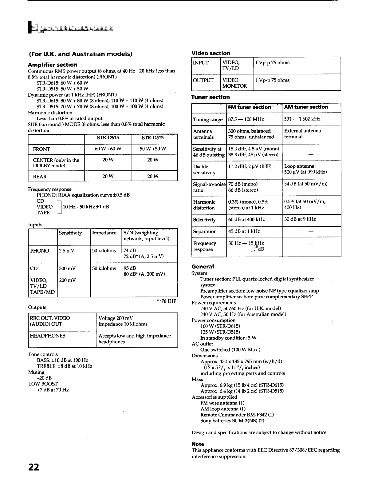
(For U.K. and Australian models)
Amplifier section
Continuous RMS power output (8 ohms, at 40 Hz - 20 kHz less than
0.8% total harmonic distortion) (FRONT)
STR-D615:60 W + 60 W
STR-D515:50 W + 50W
Dynamic power (at 1 kHz IHF) (FRONT)
STR-D615:80 W + 80 W (8 ohms), 110 W + 110 W (4 ohms)
STR-D515:70 W + 70 W (8 ohms), 100 W + 100 W (4 ohms)
Harmonic distortion
Less than 0.8% at rated output
SUR (surround) MODE (8 ohms, less than 0.8% total harmonic
distortion
STR,D615
60W +60W
20W
FRONT
CENTER (only in the
DOLBY mode)
REAR 20 W 20 W
STR-D515
50 W +50 W
20W
Frequency response
PHONO: RIAA equalization curve +0.5 dB
CD
VIDEO 10 Hz - 50 kHz _+1dB
TAPE
Inputs
Sensitivity
PHONO 2.5 mV
CD 300 mV
VIDEO, 200 mV
TV/LD
TAPE/MD
Outputs
REC OUT, VIDEO
(AUDIO) OUT
HEADPHONES
Impedance
50 kilohms
50 kilohms
S/N (weighting
network, input level)
74dB
72 dB* (A, 2.5 mV)
95 dB
80 dB* (A, 200 mV)
* '78 IHF
Voltage 200 mV
Impedance 10 kilohms
Accepts low and high impedance
headphones
Tone controls
BASS: +10 dB at 100 Hz
TREBLE: +8 dB at 10 kHz
Muting
-20 dB
LOW BOOST
+7 dB at 70 Hz
22
Video section
INPUT VIDEO,
TV/LD
1 Vp-p 75 ohms
OUTPUT VIDEO 1 Vp-p 75 ohms
iMONITOR
Tuner section
Tuning range
Antenna
terminals
Sensitivity at
46 dB quieting
Usable
sensitivity
Signal-to-noise
ratio
Harmonic
distortion
Sel_o.tivity
• jut
Separation
Frequency
response
FM l_uner section
i87.5- 108 MHz
300 ohms, balanced
75 ohms, unbalanced
18.3 dBf, 4.5 laV (mono)
38.3 dBf, 45 IxV (stereo)
11.2 dBf, 2 laV (IHF)
70 dB (mono)
66 dB (stereo)
0.3% (mono), 0.5%
(stereo) at I kHz
60 dB at 400 kHz
45 dB at I kHz
30 Hz -- 15 kHz
+ 0.5
-2 dB
*! AM tuner section
531 -- 1,602 kHz
External antenna
terminal
Loop antenna:
500 btV (at 999 kHz)
54 dB (at 50 mV/m)
0.5% (at 50 mV/m,
400 Hz)
30dB at 9kHz
General
System
Tuner section: PLL quartz-locked digital synthesizer
system
Preamplifier section: low-noise NF type equalizer amp
Power amplifier section: pure complementary SEPP
Power requirements
240 V AC, 50/60 Hz (for U.K. model)
240 V AC, 50 Hz (for Australian model)
Power consumption
160 W (STR-D615)
135 W (STR-D515)
In standby condition: 5 W
AC outlet
One switched (100 W Max.)
Dimensions
Approx. 430 x 135 x 295 mm (w/h/d)
(17 x 5 3/8 x 11 s/8 inches)
including projecting parts and controls
Mass
Approx. 6.9 kg (15 lb 4 oz) (STR-D615)
Approx. 6.4 kg (14 lb 2 oz) (STR-D515)
Accessories supplied
FM wire antenna (1)
AM loop antenna (1)
Remote Commander RM-P342 (1)
Sony batteries SUM-3(NS) (2)
Design and specifications are subject to change without notice.
Note
This appliance conforms with EEC Directive 87/308/EEC regarding
interference suppression.
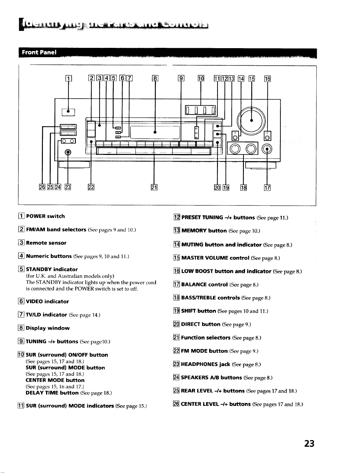
[] POWER switch
[] FM/AM band selectors (See pages 9 and 10.)
[] Remote sensor
[] Numeric buttons (See pages 9, 10 and 11.)
[] STANDBY indicator
(for U.K. and Australian models only)
The STANDBY indicator lights up when the power cord
is connected and the POWER switch is set to off.
[] VIDEO indicator
[] TV/LD indicator (See page 14.)
[] Display window
[] TUNING -/+ buttons (Seepagel0.)
[] SUR (surround) ON/OFF button
(See pages 15, 17 and 18.)
SUR (surround) MODE button
(See pages 15, 17 and 18.)
CENTER MODE button
(See pages 15, 16 and 17.)
DELAY TIME button (See page 18.)
[] SUR (surround) MODE indicators (Seepage 15.)
[] PRESET TUNING -/+ buttons (See page 11.)
[] MEMORY button (See page 10.)
[] MUTING button and indicator (See page 8.)
[] MASTER VOLUME control (See page 8.)
[] LOW BOOST button and indicator (Seepage 8.)
[] BALANCE control (See page 8.)
[] BASS/TREBLE controls (Seepage 8.)
[] SHIFT button (See pages 10 and 11.)
[] DIRECT button (See page 9.)
[] Function selectors (See page 8.)
[] FM MODE button (See page 9.)
[] HEADPHONES jack (See page 8.)
[] SPEAKERS A/B buttons (See page 8.)
[] REAR LEVEL -I+ buttons (See pages 17 and 18.)
[] CENTER LEVEL-/+ buttons (See pages 17 and 18.)
23
__L [_] _-_ _----]
IL- _ --Jl _ _ _._
i ' ,
i kl | ;i
/
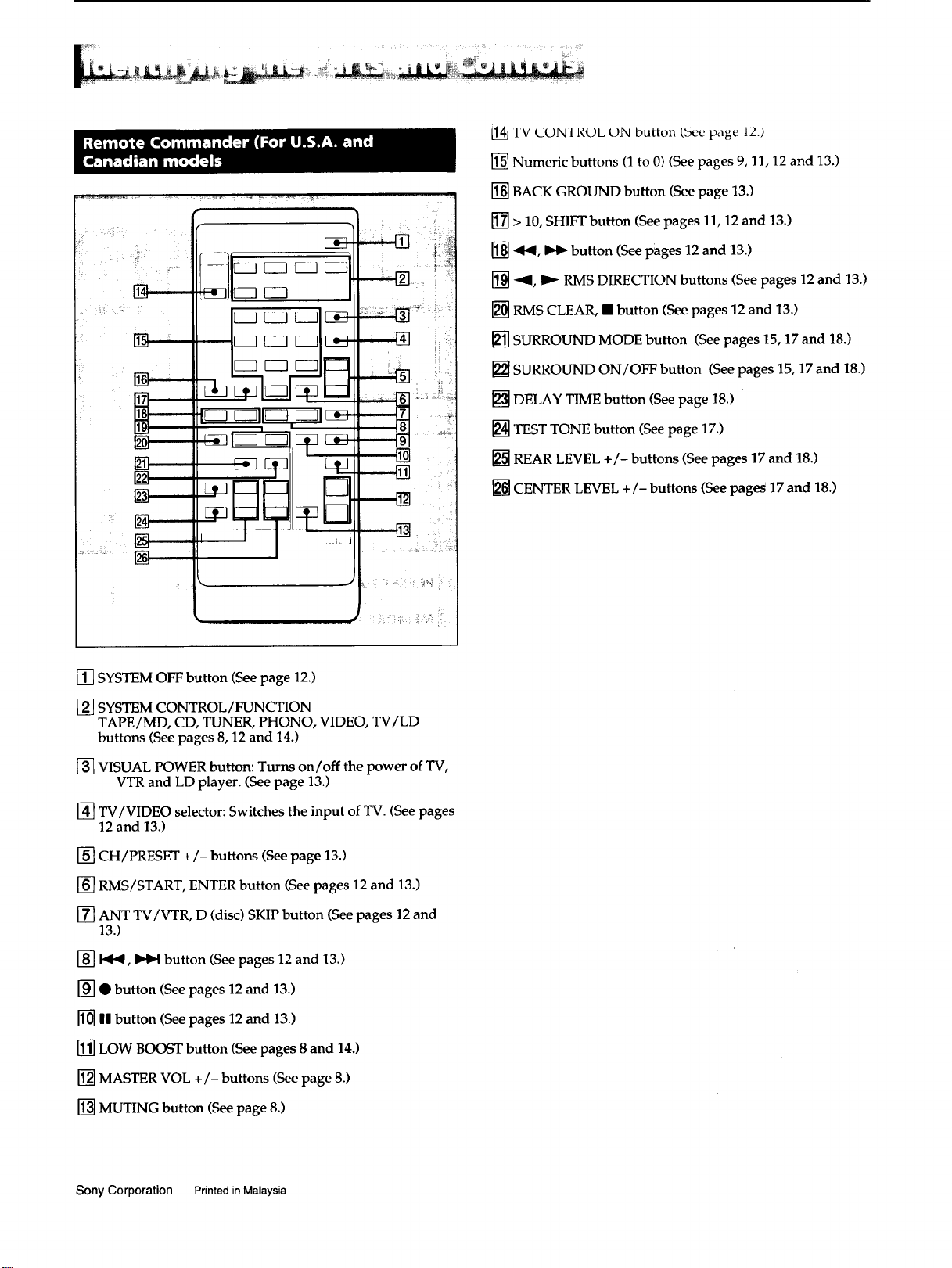
[14]TV (JDN 1R(gL ON button (bee page 12.)
[] Numeric buttons (1 to 0) (See pages 9, 11, 12 and 13.)
[] BACK GROUND button (See page 13.)
[] > 10, SHIFT button (See pages 11, 12 and 13.)
[] ._b(, _._ button (See pages 12 and 13.)
[] -'_, _'_ RMS DIRECTION buttons (See pages 12 and 13.)
[] RMS CLEAR, • button (See pages 12 and 13.)
[] SURROUND MODE button (See pages 15, 17 and !8.)
[] SURROUND ON/OFF button (See pages 15, 17 and 18.)
[] DELAY TIME button (See page 18.)
[] TEST TONE button (See page 17.)
[] REAR LEVEL +/- buttons (See pages 17 and 18.)
[] CENTER LEVEL +/- buttons (See page_ 17 and 18.)
[] SYSTEM OFF button (See page 12.)
[] SYSTEM CONTROL/FUNCTION
TAPE/MD, CD, TUNER, PHONO, VIDEO, TV/LD
buttons (See pages 8, 12 and 14.)
[] VISUAL POWER button: Turns on/off the power of TV,
VTR and LD player. (See page 13.)
[] TV/VIDEO selector: Switches the input of TV. (See pages
12 and 13.)
[] CH / PRESET +/- buttons (See page 13.)
[] RMS/START, ENTER button (See pages 12 and 13.)
[] ANT TV/VTR, D (disc) SKIP button (See pages 12 and
13.)
[] b_b_, _ button (See pages 12 and 13.)
[] • button (See pages 12 and 13.)
[] HIbutton (See pages 12 and 13.)
[] LOW BOOST button (See pages 8 and 14.)
[] MASTER VOL +/- buttons (See page 8.)
[] MUTING button (See page 8.)
Sony Corporation Printed in Malaysia
