Owner's Manual
iCRRFTSMRN'i
20.0 HP
ELECTRIC START
46" MOWER
AUTOMATIC
GARDEN TRACTOR
Model No.
917.272961
• Safety
• Assembly
• Operation
• Maintenance
• Repair Parts
CAUTION:
Read and follow all Safety
Rules and Instruction_before
operating this equipment.
For answers to your questions
about this product, Call:
1-800-659-5917
Sears Craftsman Help Line
5 am 5 pm Mon Sat
Sears, Roebuck and Co., Hoffman Estates, II 60179
Visit our Craftsman website:www.sears.com/craftsman

Warranty ...............................................2
Safety Rules ......................................... 2
Product SpeCifications .......................... 5
Assembly .............................................. 7
Operation ............................................ 12
Maintenance Schedule ...................... 19
Maintenance .......................................
Service and Adjustments .................... ',
Storage ............................................... :
Troubleshooting ................................. :
Repair Parts ........................................
Parts Ordering ..................... Back Cov
LIMITED TWO YEAR WARRANTY ON CRAFTSMAN RIDING EQUIPMENT PARTS
For two (2) years from the date of purchase, if this Craftsman Riding Equipment is
maintained, lubricated and tuned up according to the instructions in the owner's
manual, Sears will repair or replace, tree of charge, any parts found to be defective in
material or workmanship. Warranty service is available tree of charge by taking your
Craftsman riding equipment to your nearest Sears Service Center. In-home warranty
service is available but a trip charge will apply. This warranty applies only while this
product is in the United States.
This Warranty does not cover:
• Expendable items which become worn during normal use, such as blades, spark
plugs, air cleaners, belts and oil filters.
• Tire replacement or repair caused by punctures from outside objects, such as nails
thorns, stumps, or glass.
• Repairs necessary because of operator abuse, including but not limited to, damag_
caused by towing objects beyond the capability of the riding equipment, impacting
objects that bend the frame or crankshaft, or over speeding the engine.
• Repairs necessary because of operator negligence, including but not limited to,
electrical and mechanical damage caused by improper storage, failure to use the
proper grade and amount of engine oil, failure to keep the deck clear of flammable
debris, or the failure to maintain the equipment according to the instructions con-
tained in the owner's manual.
• Engine (fuel system) cleaning or repairs caused by fuel determined to be contami-
nated or oxidized (stale). In general, fuel should be used within thirty (30) days of it=
purchase date.
• Riding equipment used for commercial or rental purposes.
LIMITED 90 DAY WARRANTY ON BATTERY
For ninety (90) days from date of purchase, if any battery included with this riding
equipment proves defective in material or workmanship and our testing determines th
battery will not hold a charge, Sears will replace the battery at no charge. Warranty
service is available free of charge by taking your Craftsman riding equipment to your
nearest Sears Service Center. In-home warranty service is available but a trip charge
will apply. This warranty applies only while this product is in the United States.
To locate the nearest sears service center or to schedule in-home warranty service,
simply contact sears at 1-800-4-my-home
This Warranty gives you specific legal rights, and you may also have other rights whicl
may vary from state to state.
Sears, Roebuck and Co., D/817 WA, Hoffman Estates, IL 60179
2
IMPORTANT: This cutting machine is
capable of amputating hands and feet
and throwing objects. Failure to observe
the following safety instructions could
result in serious injury or death.
GENERAL OPERATION
• Read, understand, and follow all
instructions in the manual and on the
machine before starting.
• Only allow responsible adults, who are
familiar with the instructions, to operate
the machine.
• Clear the area of objects such as rocks,
toys, wire, etc., which could be picked
up and thrown by the blade.
• Be sure the area is clear of other
people before mowing. Stop machine if
anyone enters the area.
• Never carry passengers.
• Do not mow in reverse unless absolute-
ly necessary. Always look down and
behind before and while backing.
• Be aware of the mower discharge
direction and do not point it at anyone.
Do not operate the mower without
either the entire grass catcher or the
guard in place.
• Slow down before turning.
• Never leave a running machine
unattended. Always turn off blades, set
parking brake, stop engine, and remove
keys before dismounting.
• Turn off blades when not mowing.
• Stop engine before removing grass
catcher or unclogging chute.
• Mow only in daylight or good artificial
light.
• Do not operate the machine while
under the influence of alcohol or drugs.
• Watch for traffic when operating near or
crossing roadways.
• Use extra care when loading or
unloading the machine into a trailer or
truck.
• Data indicates that operators, age 60
years and above, are involved in a
large percentage of riding mower-
related injuries. These operators should
evaluate their ability to operate the
riding mower safely enough to protect
themselves and others from serious
injury.
SLOPE OPERATION
Slopes are a major factor related to loss-
of-controland tipover accidents, which
can result in severe injury or death. All
slopes require extra caution. If you cannot
back up the slope or if you feel uneasy on
it, do not mow it.
DO:
• Mow up and down slopes, not across.
• Remove obstacles such as rocks, tree
limbs, etc.
• Watch for holes, ruts, or bumps. Uneven
terrain could overturn the machine. Tall
grass can hide obstacles.
• Use slow speed. Choose a low gear so
that you will not have to stop or shift
while on the slope.
• Follow the manufacturer's recommen-
dations for wheel weights or counter-
weights to improve stability.
• Use extra care with grass catchers or
other attachments. These can change
the stability of the machine.
• Keep all movement on the slopes slow
and gradual. Do not make sudden
changes in speed or direction.
• Avoid starting or stopping on a slope. If
tires lose traction, disengage the blades
and proceed slowly straight down the
slope.
DO NOT:
• Do not turn on slopes unless neces-
sary, and then, turn slowly and gradual-
ly downhill, if possible.
• Do not mow near drop-offs, ditches, or
embankments. The mower could
suddenly turn over if a wheel is over the
edge of a cliff or ditch, or if an edge
caves in.
• Do not mow on wet grass. Reduced
traction could cause sliding.
• Do not try to stabilize the machine by
putting your foot on the ground.
• Do not use grass catcher on steep
slopes.
CHILDREN
Tragic accidents can occur if the operator
is not alert to the presence of children.
Children are often attracted to the
machine and the mowing activity. Never
assume that children will remain where
you last saw them.
• Keep children out of the mowing area
and under the watchful care of another
responsible adult.
• Be alert and turn machine off if children
enter the area.
3
• Before and when backing, look behind
and down for small children.
• Never carry children. They may fall off
and be seriously injured or interfere
with safe machine operation.
• Never allow children to operate the
machine.
• Use extra care when approaching blind
corners, shrubs, trees, or other objects
that may obscure vision.
SERVICE
• Use extra care in handling gasoline
and other fuels. They are flammable
and vapors are explosive.
Use only an approved container.
Never remove gas cap or add fuel
with the engine running. Allow
engine to cool before refueling, Do
not smoke.
Never refuel the machine indoors.
Never store the machine or fuel
container inside where there is an
open flame, such as a water heater.
• Never run a machine inside a closed
area.
• Keep nuts and bolts, especially blade
attachment bolts, tight and keep
equipment in good condition.
• Never tamper with safety devices.
Check their proper operation regul_
• Keep machine free of grass, leaves,
other debris build-up. Clean oil or fu
spillage. Allow machine to cool befc
storing.
• Stop and inspect the equipment if y(
strike an object. Repair, if necessar_
before restarting.
• Never make adjustments or repairs
with the engine running.
• Grass catcher components are subj_
to wear, damage, and deterioration,
which could expose moving parts or
allow objects to be thrown. Frequent
check components and replace with
manufacturer's recommended parts,
when necessary.
• Mower blades are sharp and can cul
Wrap the blade(s) or wear gloves, at
use extra caution when servicing
them.
• Check brake operation frequently.
Adjust and service as required.
• Be sure the area is clear of other
people before mowing. Stop machine
if anyone enters the area.
• Never carry passengers or children
even with the blades off.
• Do not mow in reverse unless abso-
lutely necessary. Always look down
and behind before and while backing.
• Never carry children. They may fall off
and be seriously injured or interfere
with safe machine operation.
• Keep children out of the mowing area
and under the watchful care of another
responsible adult.
• Be alert and turn machine off if
children enter the area.
• Before and when backing, look behind
and down for small children.
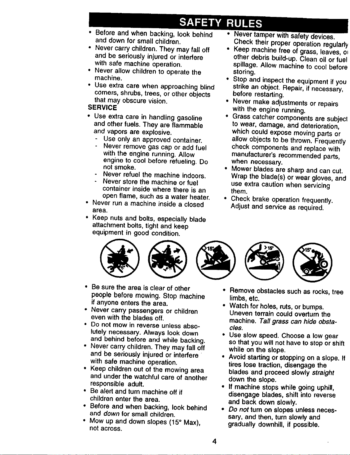
• Mow up and down slopes (15 ° Max),
not across.
• Remove obstacles such as rocks, tre,
limbs, etc.
• Watch for holes, ruts, or bumps.
Uneven terrain could overturn the
machine. Tall grass can hide obsta-
cles.
• Use slow speed. Choose a low gear
so that you will not have to stop or shi
while on the slope.
• Avoid starting or stopping on a slope.
tires lose traction, disengage the
blades and proceed slowly straight
down the slope.
• If machine stops while going uphill,
disengage blades, shift into reverse
and back down slowly.
• Do not turn on slopes unless neces-
sary, and then, turn slowly and
gradually downhill, if possible.
4
_Look for this symbol to point out
important safety precautions. It means
CAUTION!!! BECOME AWAREtl! YOUR
_FETY IS INVOLVED.
CAUTION: In order to prevent
accidental starting when setting up,
transporting, adjusting or making repairs
always disconnect spark plug wire and
place wire where it cannot contact spark
CAUTION: Do not coast down a hill in
neutral, you may lose control of the
tractor.
A(_CAUTION: Tow only the attachments
that are recommended by and comply
with specifications of the manufacturer of
your tractor. Use common sense when
towing. Operate only at the lowest
possible speed when on a slope. Too
heavy of a load, while on a slope, is
dangerous. Tires can lose traction with th
ground and cause you to lose control of
y_ur tractor.
WARNING: The engine exhaust from
this product contains chemicals known to
the State of California to cause cancer,
birth defects, or other reproductive harm.
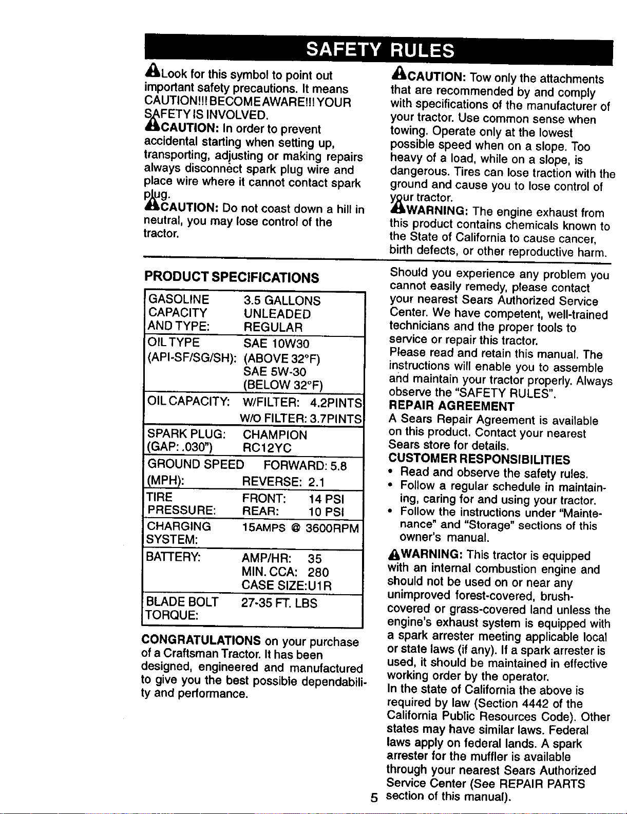
PRODUCT SPECIFICATIONS
GASOLINE
CAPACITY
AND TYPE:
OILTYPE
API-SF/SG/SH):
3.5 GALLONS
UNLEADED
REGULAR
SAE 10W30
(ABOVE 32°F)
SAE 5W-30
(BELOW 32°F)
OILCAPACITY: W/FILTER: 4.2PINTS
W/O FILTER: 3.7PINTS
SPARK PLUG: CHAMPION
GAP: .030") RC 12YC
!GROUND SPEED FORWARD: 5.8
(MPH): REVERSE: 2.1
T RE FRONT: 14 PSI
PRESSURE: REAR: 10 PSI
CHARGING 15AMPS @ 3600RPM
SYSTEM:
BATI'ERY: AMP/HR: 35
MIN. CCA: 280
CASE SIZE:U1R
BLADE BOLT 27-35 FT. LBS
TORQUE:
CONGRATULATIONS on your purchase
of a Craftsman Tractor. It has been
designed, engineered and manufactured
to give you the best possible dependabili-
ty and performance.
5
Should you experience any problem you
cannot easily remedy, please contact
your nearest Sears Authorized Service
Center. We have competent, well-trained
technicians and the proper tools to
service or repair this tractor.
Please read and retain this manual. The
instructions will enable you to assemble
and maintain your tractor properly. Alway.,
observe the "SAFETY RULES".
REPAIR AGREEMENT
A Sears Repair Agreement is available
on this product. Contact your nearest
Sears store for details.
CUSTOMER RESPONSIBILITIES
• Read and observe the safety rules.
• Follow a regular schedule in maintain-
ing, caring for and using your tractor.
• Follow the instructions under "Mainte-
nance" and "Storage" sections of this
owner's manual.
AWARNING: This tractor is equipped
with an internal combustion engine and
should not be used on or near any
unimproved forest-covered, brush-
covered or grass-covered land unless the
engine's exhaust system is equipped with
a spark arrester meeting applicable local
or state laws (if any). If a spark arrester is
used, it should be maintained in effective
working order by the operator.
In the state of California the above is
required by law (Section 4442 of the
California Public Resources Code). Other
states may have similar laws. Federal
laws apply on federal lands. A spark
arrester for the muffler is available
through your nearest Sears Authorized
Service Center (See REPAIR PARTS
section of this manual).
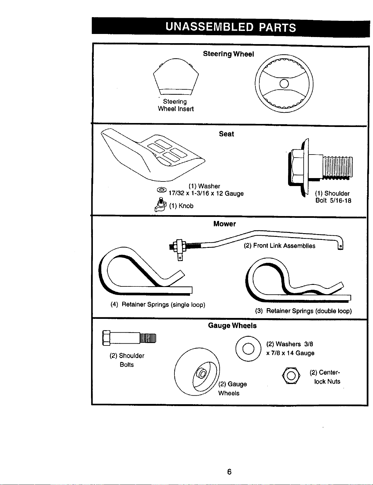
Steering
Wheel Insert
Steering Wheel
Seat
17/32 x(1) Washer
1-3/16 x 12 Gauge
t_(1) Knob
(1) Shoulder
Bolt 5/16-18
Mower
i:___Front Unk Assemblies _o
(4) Retainer Springs (single loop)
(3) Retainer Springs (double loop)
Gauge Wheels
]_ (2) Washers 3/8
(2) ShoulderBolts _(2) Gauge x 7/8 x 14_auge
Wheels
(2) Center-
lock Nuts
6
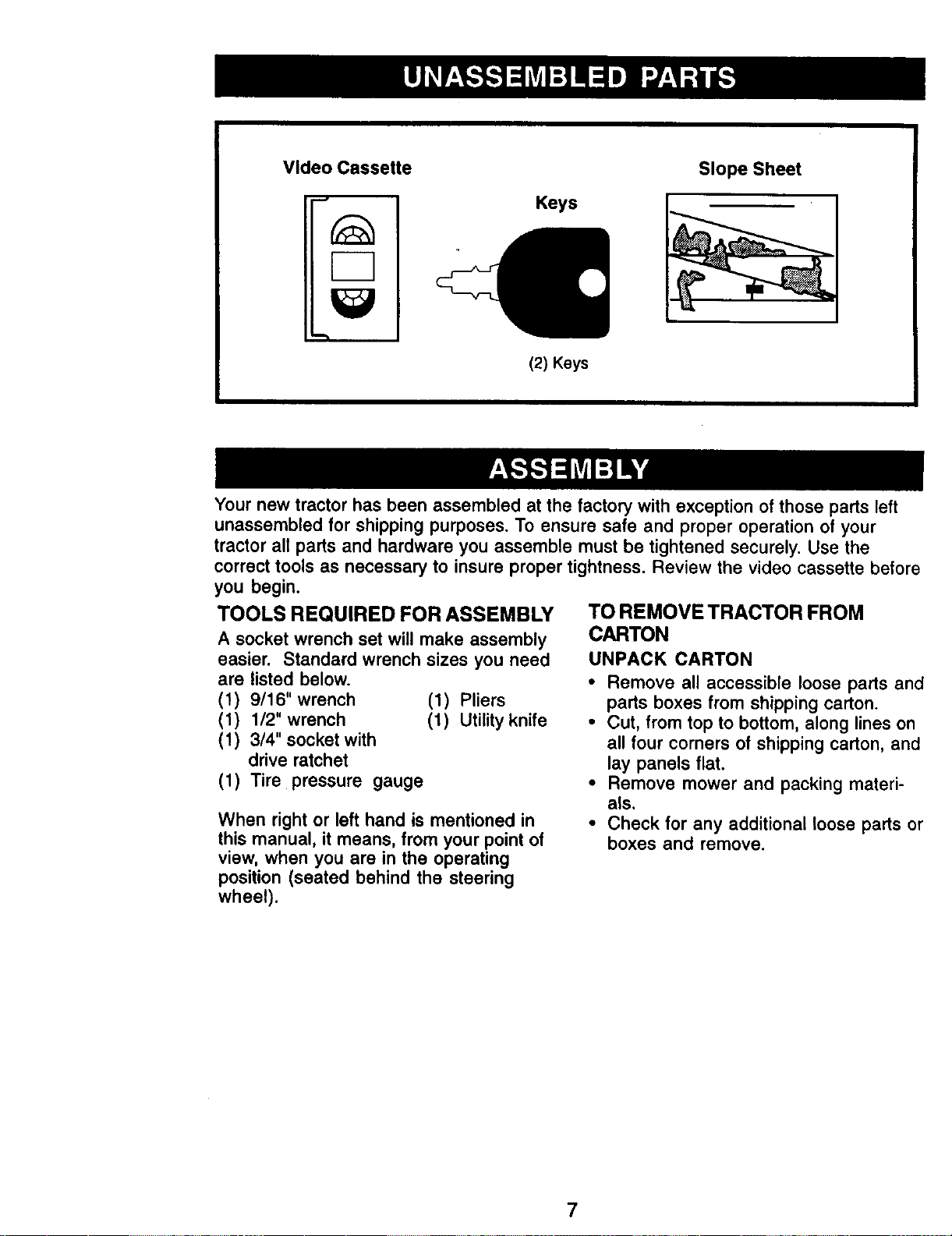
Video Cassette
Keys
(2) Keys
Slope Sheet
Your new tractor has been assembled at the factory with exception of those parts left
unassembled for shipping purposes. To ensure safe and proper operation of your
tractor all parts and hardware you assemble must be tightened securely, Use the
correct tools as necessary to insure proper tightness, Review the video cassette before
you begin.
TOOLS REQUIRED FOR ASSEMBLY
A socket wrench set will make assembly
easier. Standard wrench sizes you need
are listed below.
(1) 9/16" wrench (1) Pliers
(1) 1/2" wrench (1) Utility knife
(1) 3/4" socket with
drive ratchet
(1) Tire pressure gauge
When right or left hand is mentioned in
this manual, it means, from your point of
view, when you are in the operating
position (seated behind the steering
wheel).
TO REMOVE TRACTOR FROM
CARTON
UNPACK CARTON
• Remove all accessible loose parts and
parts boxes from shipping carton.
• Cut, from top to bottom, along lines on
all four corners of shipping carton, and
lay panels flat.
• Remove mower and packing materi-
als.
• Check for any additional loose parts or
boxes and remove.
7
BEFORE ROLLING TRACTOR OFF
SKID
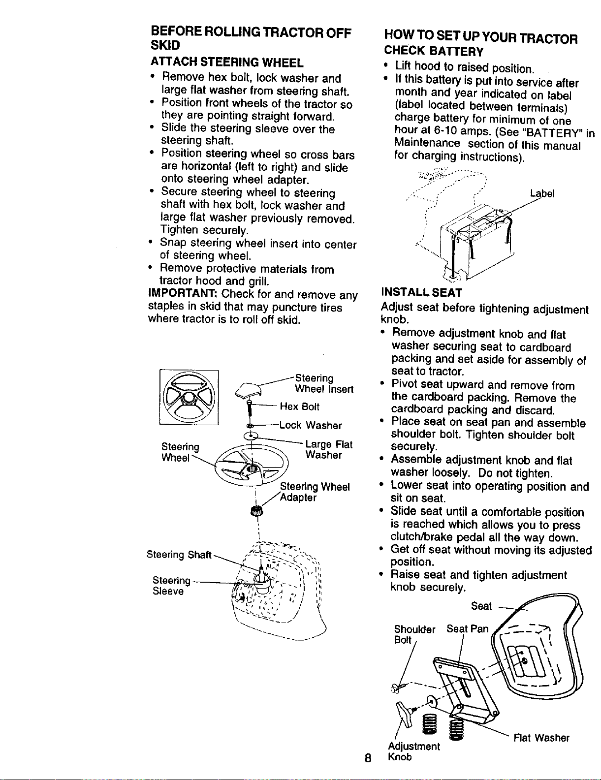
ATTACH STEERING WHEEL
• Remove hex bolt, lock washer and
large flat washer from steering shaft.
• Position front wheels of the tractor so
they are pointing straight forward.
• Slide the steering sleeve over the
steering shaft.
• Position steering wheel so cross bars
are horizontal (left to right) and slide
onto steering wheel adapter.
• Secure steering wheel to steering
shaft with hex bolt, lock washer and
large flat washer previously removed.
Tighten securely.
• Snap steering wheel insert into center
of steering wheel.
• Remove protective materials from
tractor hood and grill.
IMPORTANT: Check for and remove any
staples in skid that may puncture tires
where tractor is to roll off skid.
_ /Steering
/_ Wheel Insert
'_----- Hex Bolt
_----Lock Washer
Steering ,G_ Large Flat
i_/Adapter
Steering
Steering
Sleeve
i
HOW TO SET UP YOUR TRACTOR
CHECK BATTERY
Lift hood to raised position.
If this battery is put into service after
month and year indicated on label
(label located between terminals)
charge battery for minimum of one
hour at 6-10 amps. (See "BATTERY"
Maintenance section of this manual
for charging instructions).
L_abel
• :i?.; "__
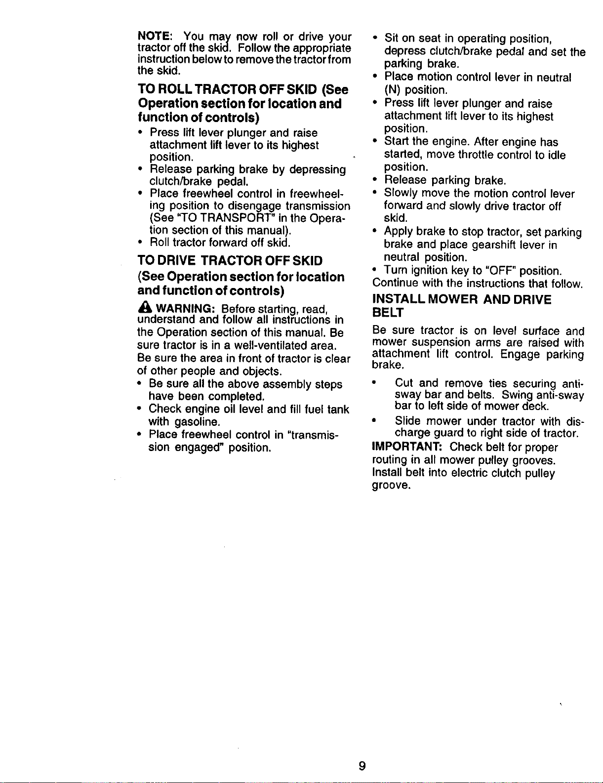
INSTALL SEAT
Adjust seat before tightening adjustmen
knob.
• Remove adjustment knob and flat
washer securing seat to cardboard
packing and set aside for assembly ol
seat to tractor.
• Pivot seat upward and remove from
the cardboard packing. Remove the
cardboard packing and discard.
• Place seat on seat pan and assemble
shoulder bolt. Tighten shoulder bolt
securely.
• Assemble adjustment knob and flat
washer loosely. Do not tighten.
• Lower seat into operating position an€
sit on seat.
• Slide seat until a comfortable position
is reached which allows you to press
clutch/brake pedal all the way down.
• Get off seat without moving its adjuste
position.
• Raise seat and tighten adjustment
knob securely.
Seat
Shoulder Seat Pan
Adjustment
8 Knob
Rat Washer
NOTE: You maly now roll or drive your
tractor off the skid. Follow the appropriate
instruction below to remove the tractor from
the skid.
TO ROLL TRACTOR OFF SKID (See
Operation section for location and
function of controls)
• Press lift lever plunger and raise
attachment lift lever to its highest
position.
• Release parking brake by depressing
clutch/brake pedal.
• Place freewheel control in freewheel-
ing position to disengage transmission
(See "TO TRANSPORT" in the Opera-
tion section of this manual).
• Roll tractor forward off skid.
TO DRIVE TRACTOR OFF SKID
(See Operation section for location
and function of controls)
_0kWARNING: Before starting read
understand and mow a nstructions in
the Operation section of this manual. Be
sure tractor is in a well-ventilated area.
Be sure the area in front of tractor is clear
of other people and objects.
• Be sure all the above assembly steps
have been completed.
• Check engine oil level and fill fuel tank
with gasoline.
• Place freewheel control in "transmis-
sion engaged" position.
• Sit on seat in operating position,
depress clutch/brake pedal and set the
parking brake.
• Place motion control lever in neutral
(N) position.
• Press lift lever plunger and raise
attachment lift lever to its highest
position.
• Start the engine. After engine has
started, move throttle control to idle
position.
• Release parking brake.
• Slowly move the motion control lever
forward and slowly drive tractor off
skid.
• Apply brake to stop tractor, set parking
brake and place gearshift lever in
neutral position.
• Turn ignition key to "OFF" position.
Continue with the instructions that follow.
INSTALL MOWER AND DRIVE
BELT
Be sure tractor is on level surface and
mower suspension arms are raised with
attachment lift control. Engage parking
brake.
Cut and remove ties securing anti-
sway bar and belts. Swing anti-sway
bar to left side of mower deck.
• Slide mower under tractor with dis-
charge guard to right side of tractor.
IMPORTANT: Check belt for proper
routing in all mower pulley grooves.
Install belt into electric clutch pulley
groove.
9
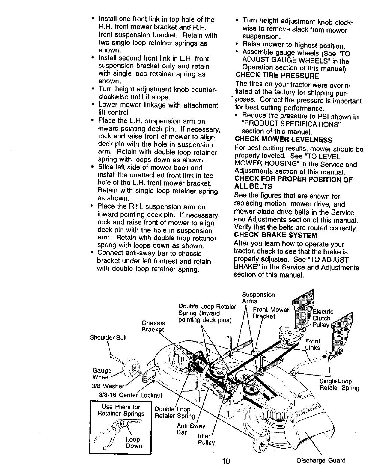
• Install one front link in top hole of the
R.H. front mower bracket and R.H.
front suspension bracket. Retain with
two single loop retainer springs as
shown.
• Install second front link in L.H. front
suspension bracket only and retain
with single loop retainer spring as
shown.
• Turn height adjustment knob counter-
clockwise until it stops.
• Lower mower linkage with attachment
lift control.
• Place the L.H. suspension arm on
inward pointing deck pin. If necessary,
rock and raise front of mower to align
deck pin with the hole in suspension
arm. Retain with double loop retainer
spring with loops down as shown.
• Slide left side of mower back and
install the unattached front link in top
hole of the L.H. front mower bracket.
Retain with single loop retainer spring
as shown.
• Place the R.H. suspension arm on
inward pointing deck pin. If necessary,
rock and raise front of mower to atign
deck pin with the hole in suspension
arm. Retain with double toop retainer
spring with loops down as shown.
• Connect anti-sway bar to chassis
bracket under left footrest and retain
with double loop retainer spring.
• Turn height adjustment knob clock-
wise to remove slack from mower
suspension.
• Raise mower to highest position.
• Assemble gauge wheels (See "TO
ADJUST GAUGE WHEELS" in the
Operation section of this manual).
CHECK TIRE PRESSURE
The tires on your tractor were overin-
flated at the factory for shipping put-
+poses. Correct tire pressure is important
for best cutting performance.
• Reduce tire pressure to PSI shown in
"PRODUCT SPECIFICATIONS"
section of this manual.
CHECK MOWER LEVELNESS
For best cutting results, mower should bc
properly leveled. See "TO LEVEL
MOWER HOUSING" in the Service and
Adjustments section of this manual.
CHECK FOR PROPER POSITION OF
ALL BELTS
See the figures that are shown for
replacing motion, mower drive, and
mower blade drive belts in the Service
and Adjustments section of this manual.
Verify that the belts are muted correctly.
CHECK BRAKE SYSTEM
After you learn how to operate your
tractor, check to see that the brake is
properly adjusted. See "TO ADJUST
BRAKE" in the Service and Adjustments
section of this manual.
Shoulder Bolt
Chassis
Bracket
Double Loop Retaler
Spring (Inward
pointing deck pins)
Suspension
Arms
Front Mower ctric
Bracket
Gauge
Wheel
3/8
3/8-16 Center Locknut
Use Pliers for
Retainer Springs Retaier Spring
Single Loop
P,etaier Spring
Loop
Down
Bar
Pulley
10 Discharge Guard
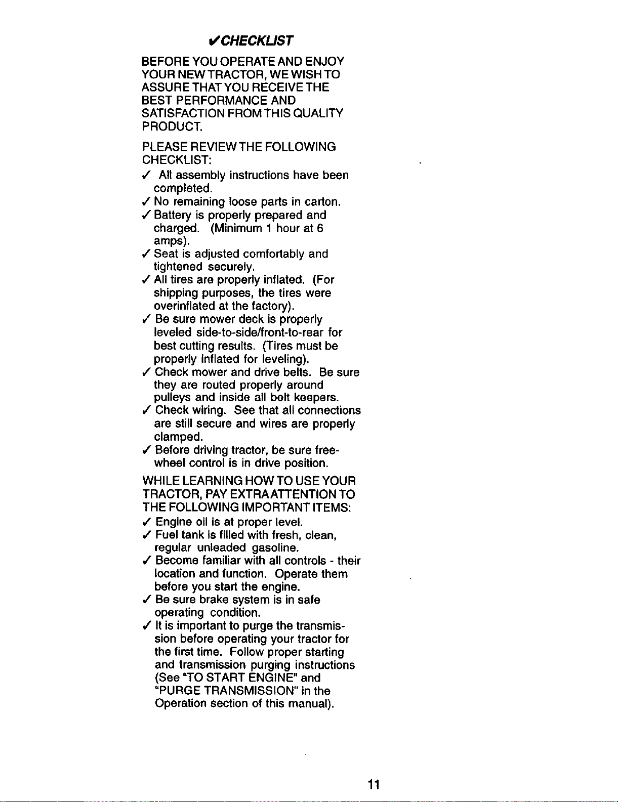
I/CHECKLIST
BEFORE YOU OPERATE AND ENJOY
YOUR NEW TRACTOR, WE WISH TO
ASSURE THAT YOU RECEIVE THE
BEST PERFORMANCE AND
SATISFACTION FROM THIS QUALITY
PRODUCT.
PLEASE REVIEWTHE FOLLOWING
CHECKLIST:
,/ All assembly instructions have been
completed.
,/No remaining loose parts in carton.
v" Battery is properly prepared and
charged. (Minimum 1 hour at 6
amps).
,/Seat is adjusted comfortably and
tightened securely.
•/ All tires are properly inflated. (For
shipping purposes, the tires were
overinflated at the factory).
,/Be sure mower deck is properly
leveled side-to-side/front-to-rear for
best cutting results. (Tires must be
properly inflated for leveling).
,/Check mower and drive belts. Be sure
they are routed properly around
pulleys and inside all belt keepers.
,/Check wiring. See that all connections
are still secure and wires are properly
clamped.
/ Before driving tractor, be sure free-
wheel control is in drive position.
WHILE LEARNING HOW TO USE YOUR
TRACTOR, PAY EXTRAATTENTION TO
THE FOLLOWING IMPORTANT ITEMS:
/ Engine oil is at proper level.
,/Fuel tank is filled with fresh, clean,
regular unleaded gasoline.
/ Become familiar with all controls - their
location and function. Operate them
before you start the engine.
,/Be sure brake system is in safe
operating condition.
/ It is important to purge the transmis-
sion before operating your tractor for
the first time. Follow proper starting
and transmission purging instructions
(See "TO START ENGINE" and
"PURGE TRANSMISSION" in the
Operation section of this manual).
11
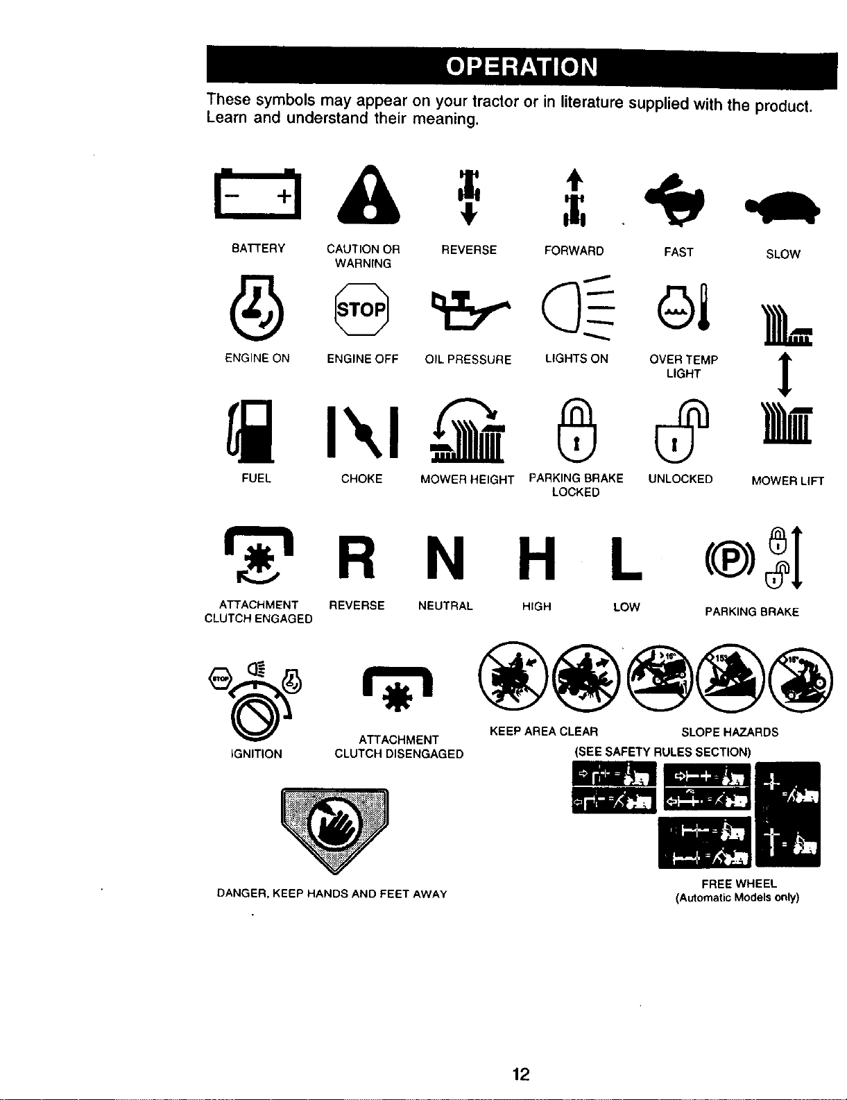
These symbols may appear on your tractor or in literature supplied with the product.
Learn and understand their meaning.
BATTERY CAUTION OR
WARNING
REVERSE FORWARD FAST SLOW
ENGINE ON ENGINE OFF OIL PRESSURE
t'.,t
LIGHTS ON
FUEL CHOKE MOWER HEIGHT PARKING BRAKE UNLOCKED MOWER LIFT
LOCKED
R N H L
ATTACHMENT REVERSE
CLUTCH ENGAGED
NEUTRAL HIGH LOW
PARKING BRAKE
KEEP AREA CLEAR SLOPE HAZARDS
IGNITION
ATTACHMENT
CLUTCH DISENGAGED
(SEE SAFETY RULES SECTION)
DANGER, KEEP HANDS AND FEET AWAY
FREE WHEEL
(Automatic Models only)
12
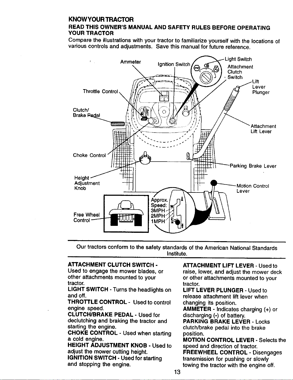
KNOWYOURTRACTOR
READ THIS OWNER'S MANUAL AND SAFETY RULES BEFORE OPERATING
YOUR TRACTOR
Compare the illustrations with your tractor to familiarize yourself with the locations of
various controls and adjustments. Save this manual for future reference.
Ammeter
Throttle Control
Clutch/
Brake
Ignition Switch
Attachment
Clutch
• Switch
Lever
Plunger
Attachment
Lift Lever
_g Brake Lever
Height
Adjustment -Motion Control
Knob Lever
Approx.
Speed:
FreeWheel
Our tractors conform to the safety standards of the American National Standards
Institute.
ATTACHMENT CLUTCH SWITCH -
Used to engage the mower blades, or
other attachments mounted to your
tractor.
LIGHT SWITCH - Turns the headlights on
and off.
THROTTLE CONTROL - Used to control
engine speed.
CLUTCH/BRAKE PEDAL - Used for
declutching and braking the tractor and
starting the engine.
CHOKE CONTROL - Used when starting
a cold engine.
HEIGHT ADJUSTMENT KNOB - Used to
adjust the mower cutting height.
IGNITION SWITCH - Used for starting
and stopping the engine.
13
ATTACHMENT LIFT LEVER - Used to
raise, lower, and adjust the mower deck
or other attachments mounted to your
tractor.
LIFT LEVER PLUNGER - Used to
release attachment lift lever when
changing its position.
AMMETER - Indicates charging (+) or
discharging (-) of battery.
PARKING BRAKE LEVER - Locks
clutch/brake pedal into the brake
position.
MOTION CONTROL LEVER - Selects the
speed and direction of tractor.
FREEWHEEL CONTROL - Disengages
transmission for pushing or slowly
towing the tractor with the engine off.
The operation of any tractor can result in foreign objects thrown into
the eyes, which can result in severe eye damage. Always wear safety
glasses or eye shields while operating your tractor or perlorming any
adjustments or repairs. We recommend a wide vision safety mask
over spectacles or standard safety glasses.
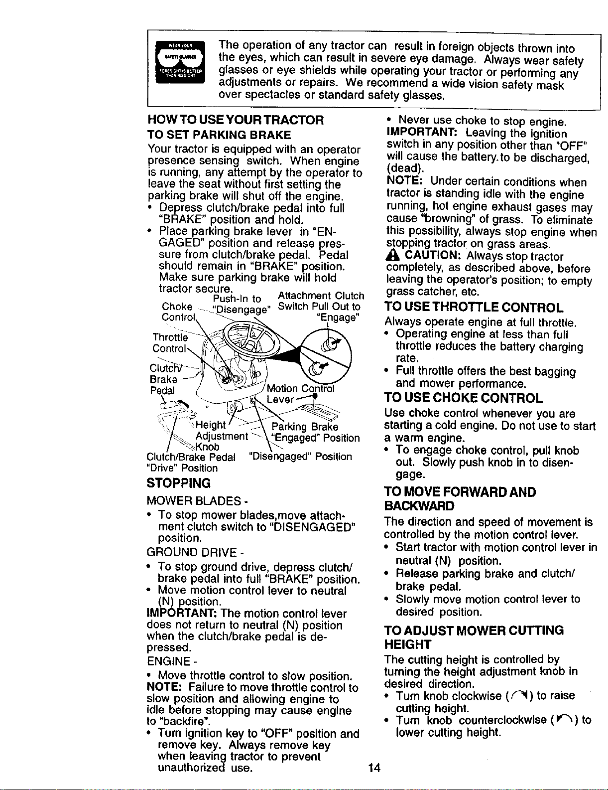
HOW TO USE YOUR TRACTOR
TO SET PARKING BRAKE
Your tractor is equipped with an operator
presence sensing switch. When engine
is running, any attempt by the operator to
leave the seat without first setting the
parking brake will shut off the engine.
• Depress clutch/brake pedal into full
"BRAKE" position and hold.
• Place parking brake lever in "EN-
GAGED" position and release pres-
sure from clutch/brake pedal. Pedal
should remain in "BRAKE" position.
Make sure parking brake will hold
tractor secure.
Push-In to Attachment Clutch
Choke ....t'Disengage" SwitchPullOut to
Control\ "Engage"
Throti_e....
Pedal
Parking Brake
Position
Clutch/Brake Pedal "Disengaged" Position
"Drive" Position
STOPPING
MOWER BLADES -
• To stop mower blades,move attach-
ment clutch switch to "DISENGAGED"
position.
GROUND DRIVE -
• To stop ground drive, depress clutch/
brake pedal into full "BRAKE" position.
• Move motion control lever to neutral
(N) position.
iMPORTANT; The motion control lever
does not return to neutral (N) position
when the clutch/brake pedal is de-
pressed.
ENGINE -
• Move throttle control to slow position.
NOTE: Failure to move throttle control to
slow position and allowing engine to
idle before stopping may cause engine
to "backfire".
• Turn ignition key to "OFF" position and
remove key. Always remove key
when leaving tractor to prevent
unauthorized use.
• Never use choke to stop engine.
IMPORTANT: Leaving the ignition
switch in any position other than "OFF"
will cause the battery.to be discharged,
(dead).
NOTE: Under certain conditions when
tractor is standing idle with the engine
running, hot engine exhaust gases ma!
cause "browning" of grass. To eliminat*
this possibility, always stop engine wh_
_lopping tractor on grass areas.
CAUTION: Always stop tractor
completely, as described above, befor_
leaving the operator's position; to empt'
grass catcher, etc.
TO USE THROTTLE CONTROL
Always operate engine at full throttle.
• Operating engine at less than full
throttle reduces the battery charging
rate.
• Fu_lthrottle offers the best bagging
and mower performance.
TO USE CHOKE CONTROL
Use choke control whenever you are
starting a cold engine. Do not use to sta
a warm engine.
• To engage choke control, pull knob
out. Slowly push knob in to disen-
gage.
TO MOVE FORWARD AND
BACKWARD
The direction and speed of movement i=
controlled by the motion control lever.
• Start tractor with motion control lever
neutral (N) position.
* Release parking brake and clutch/
brake pedal.
• Slowly move motion control lever to
desired position.
TO ADJUST MOWER CUTTING
HEIGHT
The cutting height is controlled by
turning the height adjustment knob in
desired direction.
• Turn knob clockwise ((_1) to raise
cutting height.
• Tum knob counterclockwise (If_) tc
lower cutting height.
14
The cutting height range is approxi-
mately 1-1/2" to 4". The heights are
measured from the ground to the blade
tip with the engine not running. These
heights are approximate and may vary
depending upon soil conditions, height
of grass and types of grass being
mowed.
• The average lawn should be cut to
approximately 2-1/2 inches during the
cool season and to over 3 inches
during hot months. For healthier and
better looking lawns, mow often and
after moderate growth.
• For best cutting performance, grass
over 6 inches in height should be
mowed twice. Make the first cut
relatively high; the second to desired
height.
TO ADJUST GAUGE WHEELS
Gauge wheels are properly adjusted
when they are slightly off the ground
when mower is at the desired cutting
height in operating position. Gauge
wheels then keep the deck in proper
position to help prevent scalping in most
terrain conditions.
• Adjust gauge wheels with tractor on a
flat level surface.
• Adjust mower to desired cutting height
(See "TO ADJUST MOWER CUTTING
HEIGHT" in the Operation section of
this manual).
• With mower in desired height of cut
position, gauge wheels should be
assembled so they are slightly off the
ground. Install gauge wheel in
appropriate hole with shoulder bolt, 3/
8 washer, and 3/8-16 Iocknut and
tighten securely.
• Repeat for opposite side installing
gauge wheel in same adjustment hole.
3/8-16
Locknut \
Gauge
Wheel
Mounting
Bracket
3/8
Gauge Wheel
\
Shoulder
,_ Bolt
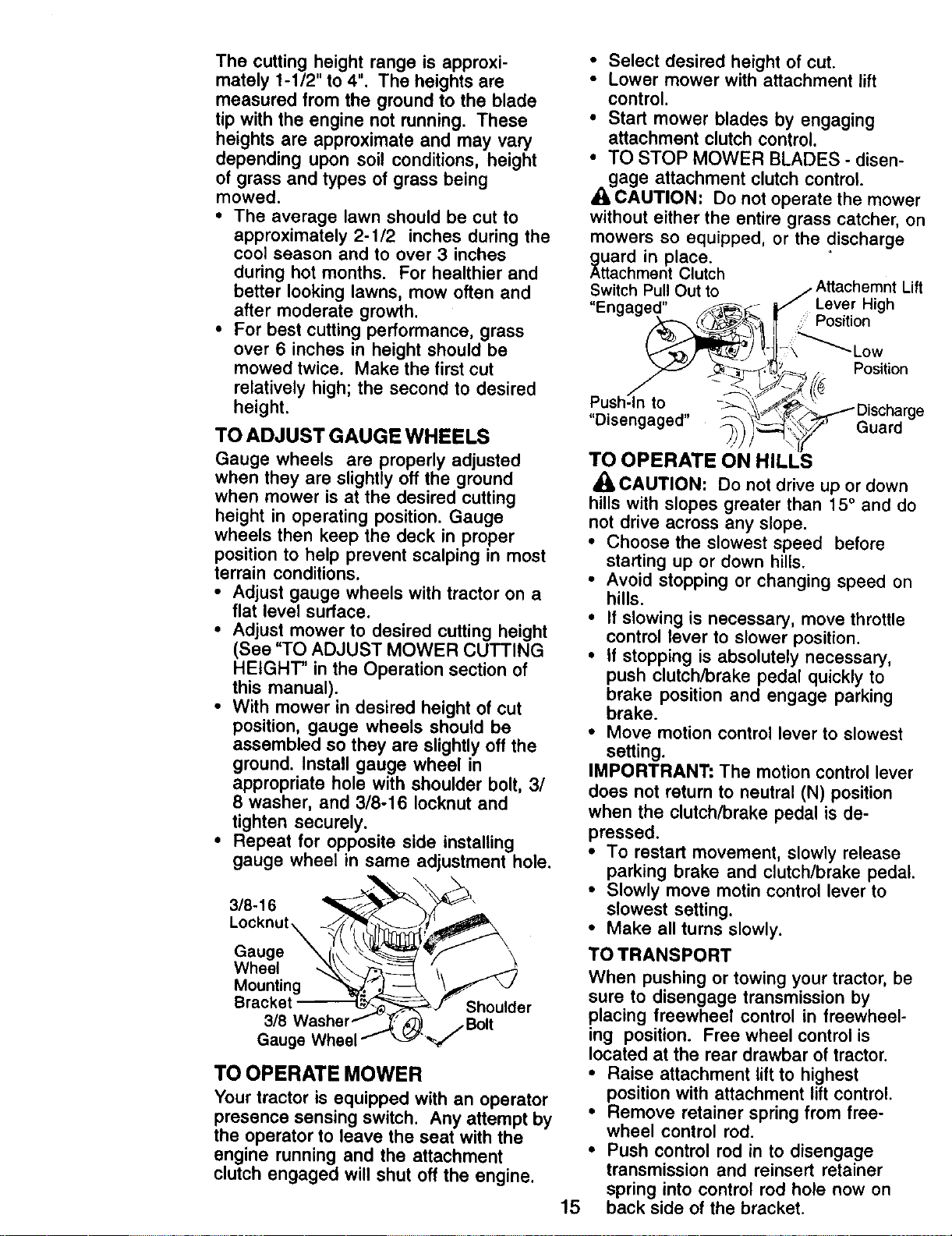
TO OPERATE MOWER
Your tractor is equipped with an operator
presence sensing switch. Any attempt by
the operator to leave the seat with the
engine running and the attachment
clutch engaged will shut off the engine.
• Select desired height of cut.
• Lower mower with attachment lift
control.
• Start mower blades by engaging
attachment clutch control.
• TO STOP MOWER BLADES - disen-
gage attachment clutch control
CAUTION' Do not operate the mower
without either the entire grass catcher, Ol
mowers so equipped, or the discharge
_uard in place.
ttachment Clutch
SwitchPullOut to ,Attachernnt Lif
"Enaaned" _ _ I_" Lever High
_-_ '__,_, Position
ush-lnto _ \\_-_,_" Dscharg
"Disengaged' _ )'_',_\_'-_'_ Guard
TO OPERATE ON HILLS
CAUTION: Do not drive up or down
hills with slopes greater than 15° and do
not drive across any slope.
• Choose the slowest speed before
starting up or down hills.
• Avoid stopping or changing speed on
hills.
• If slowing is necessary, move throttle
control lever to slower position.
• If stopping is absolutely necessary,
push clutch/brake pedal quickly to
brake position and engage parking
brake.
• Move motion control lever to slowest
setting.
IMPORTRANT; The motion control lever
does not return to neutral (N) position
when the clutch/brake pedal is de-
pressed.
• To restart movement, slowly release
parking brake and clutch/brake pedal.
• Slowly move motin control lever to
slowest setting.
• Make all turns slowly.
15
TO TRANSPORT
When pushing or towing your tractor, be
sure to disengage transmission by
placing freewheel control in freewheel-
ing position. Free wheel control is
located at the rear drawbar of tractor.
• Raise attachment lift to highest
position with attachment lift control.
• Remove retainer spring from free-
wheel control rod.
• Push control rod in to disengage
transmission and reinsert retainer
spring into control rod hole now on
back side of the bracket.
• Do not push or tow tractor at more
than two (2) MPH.
• To reengage transmission, reverse
above procedure..
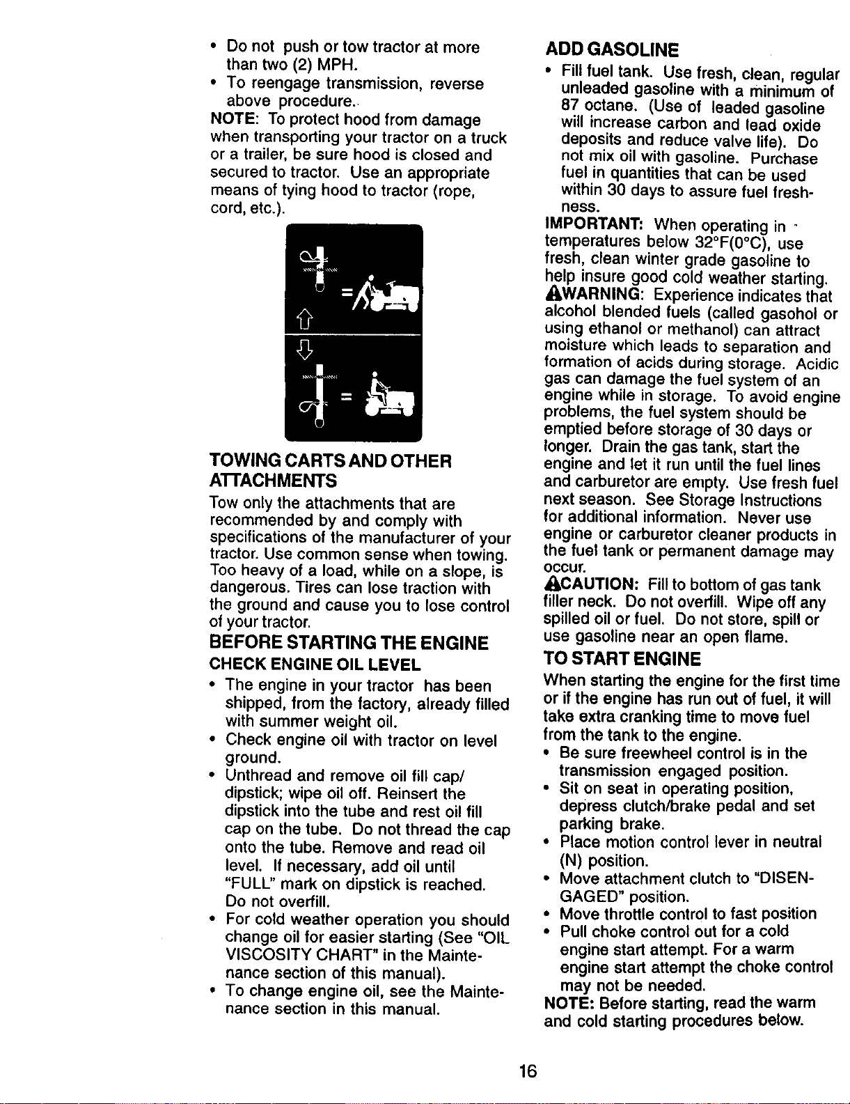
NOTE: To protect hood from damage
when transporting your tractor on a truck
or a trailer, be sure hood is closed and
secured to tractor. Use an appropriate
means of tying hood to tractor (rope,
cord, etc.).
TOWING CARTS AND OTHER
A'I-rACHMENTS
Tow only the attachments that are
recommended by and comply with
specifications of the manufacturer of your
tractor. Use common sense when towing.
Too heavy of a load, while on a slope, is
dangerous. Tires can lose traction with
the ground and cause you to lose control
of your tractor.
BEFORE STARTING THE ENGINE
CHECK ENGINE OIL LEVEL
• The engine in your tractor has been
shipped, from the factory, already filled
with summer weight oil.
• Check engine oil with tractor on level
ground.
• Unthread and remove oil fill cap/
dipstick; wipe oil off. Reinsert the
dipstick into the tube and rest oil fill
cap on the tube. Do not thread the cap
onto the tube. Remove and read oil
level. If necessary, add oil until
"FULL" mark on dipstick is reached.
Do not overfill.
• For cold weather operation you should
change oil for easier starting (See "OIL
VISCOSITY CHART" in the Mainte-
nance section of this manual).
• To change engine oil, see the Mainte-
nance section in this manual.
ADD GASOLINE
• Fill fuel tank. Use fresh, clean, regular
unleaded gasoline with a minimum of
87 octane. (Use of leaded gasoline
will increase carbon and lead oxide
deposits and reduce valve life). Do
not mix oil with gasoline. Purchase
fuel in quantities that can be used
within 30 days to assure fuel fresh-
ness.
IMPORTANT: When operating in °
temperatures below 32°F(0°C), use
fresh, clean winter grade gasoline to
help insure good cold weather starting.
_WARNING: Experience indicates that
alcohol blended fuels (called gasohol or
using ethanol or methanol) can attract
moisture which leads to separation and
formation of acids during storage. Acidic
gas can damage the fuel system of an
engine while in storage. To avoid engine
problems, the fuel system should be
emptied before storage of 30 days or
longer. Drain the gas tank, start the
engine and let it run until the fuel lines
and carburetor are empty. Use fresh fuel
next season. See Storage Instructions
for additional information. Never use
engine or carburetor cleaner products in
the fuel tank or permanent damage may
occur.
ACAUTION: Fill to bottom of gas tank
filler neck. Do not overfill. Wipe off any
spilled oil or fuel. Do not store, spill or
use gasoline near an open flame.
TO START ENGINE
When starting the engine for the first time
or if the engine has run out of fuel, it will
take extra cranking time to move fuel
from the tank to the engine.
• Be sure freewheel control is in the
transmission engaged position.
• Sit on seat in operating position,
depress clutch/brake pedal and set
parking brake.
• Place motion control lever in neutral
(N) position.
• Move attachment clutch to "DISEN-
GAGED" position.
• Move throttle control to fast position
• Pull choke control out for a cold
engine start attempt. For a warm
engine start attempt the choke control
may not be needed.
NOTE: Before starting, read the warm
and cold starting procedures below.
16
• Insert key into ignition and turn key
clockwise to "START" position and
release key as soon as engine starts.
Do not run starter continuously for
more than fifteen seconds per minute.
If the engine does not start after
several attempts, push choke control
in, wait a few minutes and try again. If
engine still does not start, pull the
choke control out and retry.
WARM WEATHER STARTING (50 ° F and
above)
• When engine starts, slowly push
choke control in until the engine
begins to run smoothly, tf the engine
starts to run roughly, pull the choke
control out slightly for a few seconds
and then continue to push the control
in slowly.
• The attachments and ground drive can
now be used. If the engine does not
accept the load, restart the engine and
allow it to warm up for one minute
using the choke as described above.
COLD WEATHER STARTING (50 ° F and
below)
• When engine starts, slowly push
choke control in until the engine
begins to run smoothly. Continue to
push the choke control in small steps
allowing the engine to accept small
changes in speed and load, until the
choke control is fully in. If the engine
starts to run roughly, pull the choke
control out slightly for a few seconds
and then continue to push the control
in slowly. This may require an engine
warm-up period from several seconds
to several minutes, depending on the
temperature.
AUTOMATIC TRANSMISSION WARM UP
• Before driving the unit in cold weather,
the transmission should be warmed up
as follows:
• Be sure the tractor is on level
ground.
• Place the motion control lever in
neutral. Release the parking brake
and let the clutch/brake
slowly return to operating position.
• Allow one minute for transmission to
warm up. This can be done during
the engine warm up period.
• The attachments can be used during
the engine warm-up period after the
transmission has been warmed up
and may require the choke control be
pulled out slightly.
NOTE: If at a high altitude (above 3000
feet) or in cold temperatures (below 32
F) the carburetor fuel mixture may need
to be adjusted for best engine perfor-
mance. See "TO ADJUST CARBURE-
TOR" in the Service and Adjustments
section of this manual.
PURGE TRANSMISSION
CAUTION: Never engage or disen-
gage freewheel lever while the engine is
running.
To ensure proper operation and perfor-
mance, it is recommended that the
transmission be purged before operating
tractor for the first time. This procedure
will remove any trapped air inside the
transmission which may have developed
during shipping of your tractor.
IMPORTANT: Should your transmission
require removal for service or replace-
ment, it should be purged after reinstalla-
tion before operating the tractor.
• Place tractor safely on level surface
with engine off and parking brake set.
• Disengage transmission by placing
freewheel control in freewheeling
position (See "TO TRANSPORT" in
this section of manual).
• Sitting in the tractor seat, start engine.
After the engine is running, move
throttle control to slow position. With
motion control lever in neutral (N)
position, slowly disengage clutch/
brake pedal.
• Move motion control lever to full
forward position and hold for five (5)
seconds. Move lever to full reverse
position and hold for five (5) seconds.
Repeat this procedure three (3) times.
NOTE; During this procedure there will
be no movement of drive wheels. The air
is being removed from hydraulic drive
system.
• Move motion control lever to neutral
(N) position. Shut- off engine and set
parking brake.
• Engage transmission by placing
freewheel control in driving position
(See "TO TRANSPORT" in this section
of manual).
17
• Sitting in the tractor seat, start engine.
After the engine is running, move
throttle control to half (1/2) speed. With
motion control lever in neutral (N)
position, slowly disengage clutch/
brake pedal.
• Slowly move motion control lever
forward, after the tractor moves
approximately five (5) feet, slowly
move motion control lever to reverse
position. After the tractor moves
approximately five (5) feet return the
motion control lever to the neutral (N)
position. Repeat this procedure with
the motion control lever three (3)
times.
• Your tractor is now purged and now
ready for normal operation.
MOWING TIPS
• Tire chains cannot be used when the
mower housing is attached to tractor.
• Mower should be properly leveled for
best mowing performance. See "TO
LEVEL MOWER HOUSING" in the
Service and Adjustments section of
this manual.
• The left hand side of mower should be
used for trimming.
• Drive so that clippings are discharged
onto the area that has been cut. Have
the cut area to the right of the tractor.
This will result in a more even distribu-
tion of clippings and more uniform
cutting.
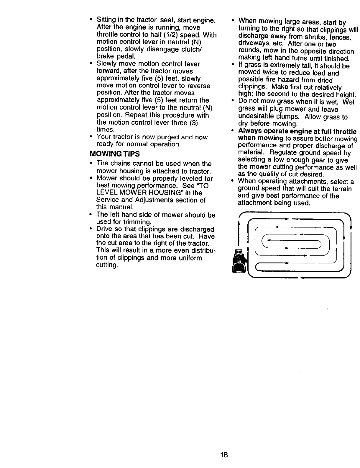
• When mowing large areas, start by
turning to the right so that clippings will
discharge away from shrubs, fences,
driveways, etc. After one or two
rounds, mow in the opposite direction
making left hand turns until finished.
• If grass is extremely tall, it should be
mowed twice to reduce load and
possible fire hazard from dried
clippings. Make first cut relatively
high; the second to the desired height.
• Do not mow grass when it is wet. Wet
grass will plug mower and leave
undesirable clumps. Allow grass to
dry before mowing.
• Always operate engine at full throttle
when mowing to assure better mowing
performance and proper discharge of
material. Regulate ground speed by
selecting a low enough gear to give
the mower cutting performance as well
as the quality of cut desired.
• When operating attachments, select a
ground speed that will suit the terrain
and give best performance of the
attachment being used.
18
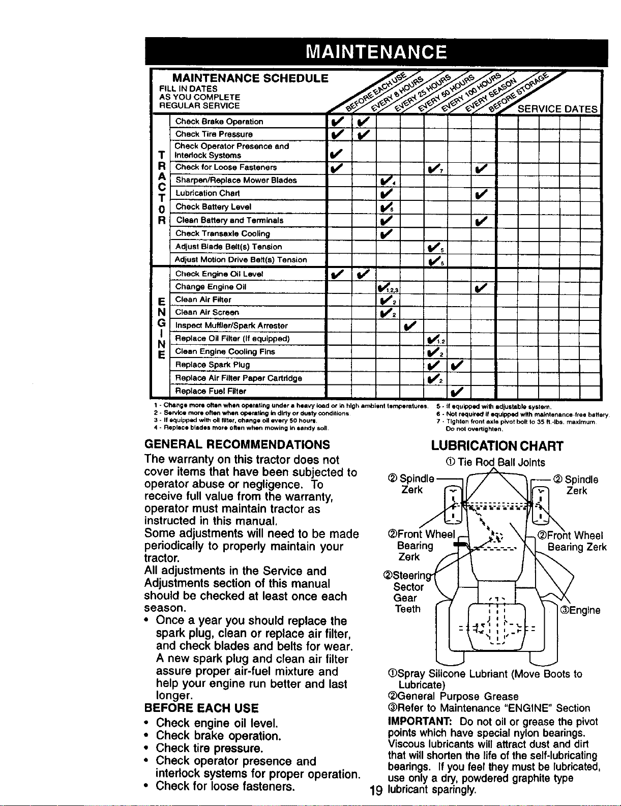
FILL IN DATES
ASYouCOMPLETE
.EGO...BEBV,CE
DATES
_=n_
Check Brake Operation
Check Tire Pressure _V'
Check Operator Presence and
T Interlock Systems I_
R Check for Loose Fasteners iJ/ Ik_7 I_
Sharpen/Replace Mower Blades _4
= T Lubrication Chad V _
0 Check Battery Level
R Clean Battery and Terminals V'
Check Trensaxle Cooling V'
Adjust Blade Belt(s)Tension I##s
v',
Adjust Motion Drive Belt(s) Tension
Check Engine Oil Level _
Change Engine Oil 1_,2,3 V _
E Clean Aii" Filter I_2
N Ctean Air Screen _z
IG Inspect Muffler/Spark Arrester I##
Replace Oil Filter (If equipped) ql_t.2
N Clean Engine Cooling Fins V'2
Replace Spark Plug V'
Replace Air Filter Paper Certndge V'2
Replace Fuel Filter I_
1 - Change more often when cpemlthg under a heavy 4oad or _n high ambient temperatures 5 - if equipped with adjusthble system.
2 - Service more o_en when opemlthg th dirty or dusty conditions¸ 6 - Not required I! equipped with mainlenance-free bahery
3 - If equLpped with oll filter, change oil every 50 houri, 7 - Tighten front axle pivot bolt Io 35 ft-Ibs, maximum¸
4 - Replace bllde s more oflgn when mowing in selxly sol1. Do not overtighten.
GENERAL RECOMMENDATIONS
The warranty on this tractor does not
cover items that have been subjected to
operator abuse or negligence. To
receive full value from the warranty,
operator must maintain tractor as
instructed in this manual,
Some adjustments will need to be made
periodically to properly maintain your
tractor.
All adjustments in the Service and
Adjustments section of this manual
should be checked at least once each
season.
• Once a year you should replace the
spark plug, clean or replace air filter,
and check blades and belts for wear.
A new spark plug and clean air tilter
assure proper air-fuel mixture and
help your engine run better and last
longer.
BEFORE EACH USE
• Check engine oil level.
• Check brake operation.
• Check tire pressure.
• Check operator presence and
interlock systems for proper operation.
• Check for loose fasteners.
Zerk
LUBRICATION CHART
• Tie RodBallJoints
)indle
Zerk
(_Front Wheel Wheel
Bearing Bearing Zerk
Zerk
_)Steerin
Sector
Gear
Teeth
(_Engine
19
OSpray Silicone Lubdant (Move Boots to
Lubricate)
_General Purpose Grease
(_Refer to Maintenance "ENGINE" Section
IMPORTANT: Do not oil or grease the pivot
points which have special nylon bearings.
Viscous lubricants will attract dust and dirt
that will shorten the life of the self-lubdcating
bearings. If you feel they must be lubricated,
use only a dry, powdered graphite type
lubricant sparingly.
TRACTOR
Always observe safety rules when
performing any maintenance.
BRAKE OPERATION
If tractor requires more than six (6) feet
stopping distance at high speed in
highest gear, then brake must be
adjusted. (See "TO ADJUST BRAKE" in
the Service and Adjustments section of
this manual).
TIRES
• Maintain proper air pressure in all tires
(See "PRODUCT SPECIFICATIONS"
section of this manual).
• Keep tires free of gasoline, oil, or
insect control chemicals which can
harm rubber.
• Avoid stumps, stones, deep ruts, sharp
objects and other hazards that may
cause tire damage.
NOTE: To seal tire punctures and
prevent flat tires due to slow leaks, tire
sealant may be purchased from your
local parts dealer. "13resealant also
prevents tire dry rot and corrosion.
OPERATOR PRESENCE SYSTEM
Be sure operator presence and interlock
systems are working properly. If your
tractor does not function as described,
repair the problem immediately.
• The engine should not start unless the
clutch/brake pedal is fully depressed
and attachement clutch control is in
the disengaged position.
• When the engine is running, any
attempt by the operator to leave the
seat without first setting the parking
brake should shut off the engine.
• When the engine is running and the
attachment clutch is engaged, any
attempt by the operator to leave the
seat should shut off the engine.
• The attachment clutch should never
operate unless the operator is in the
seat.
BLADE CARE
For best results mower blades must be
kept sharp. Replace bent or damaged
blades.
BLADE REMOVAL
• Raise mower to highest position to
allow access to blades.
• Remove hex bolt, lock washer and flat
washer securing blade.
• Install new or resharpened blade with
trailing edge up towards deck as
shown.
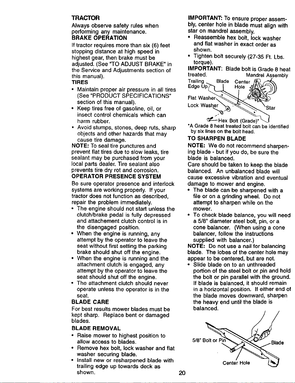
IMPORTANT: To ensure proper assem-
bly, center hole in blade must align with
star on mandrel assembly.
• Reassemble hex bolt, lock washer
and flat washer in exact order as
shown.
• Tighten bolt securely (27-35 Ft. Lbs.
torque).
IMPORTANT: Blade bolt is Grade 8 heat
treated. Mandrel Assembly
Trailing Blade Center
Hole
Flat
Lock Washel
_--Hex Bolt (Grade)*
*A Grade 8 heat treated bolt can be identified
by six lines on the bolt head.
TO SHARPEN BLADE
NOTE: We do not recommend sharpen-
ing blade - but if you do, be sure the
blade is balanced.
Care should be taken to keep the blade
balanced. An unbalanced blade will
cause excessive vibration and eventual
damage to mower and engine.
• The blade can be sharpened with a
file or on a grinding wheel. Do not
attempt to sharpen while on the
mower.
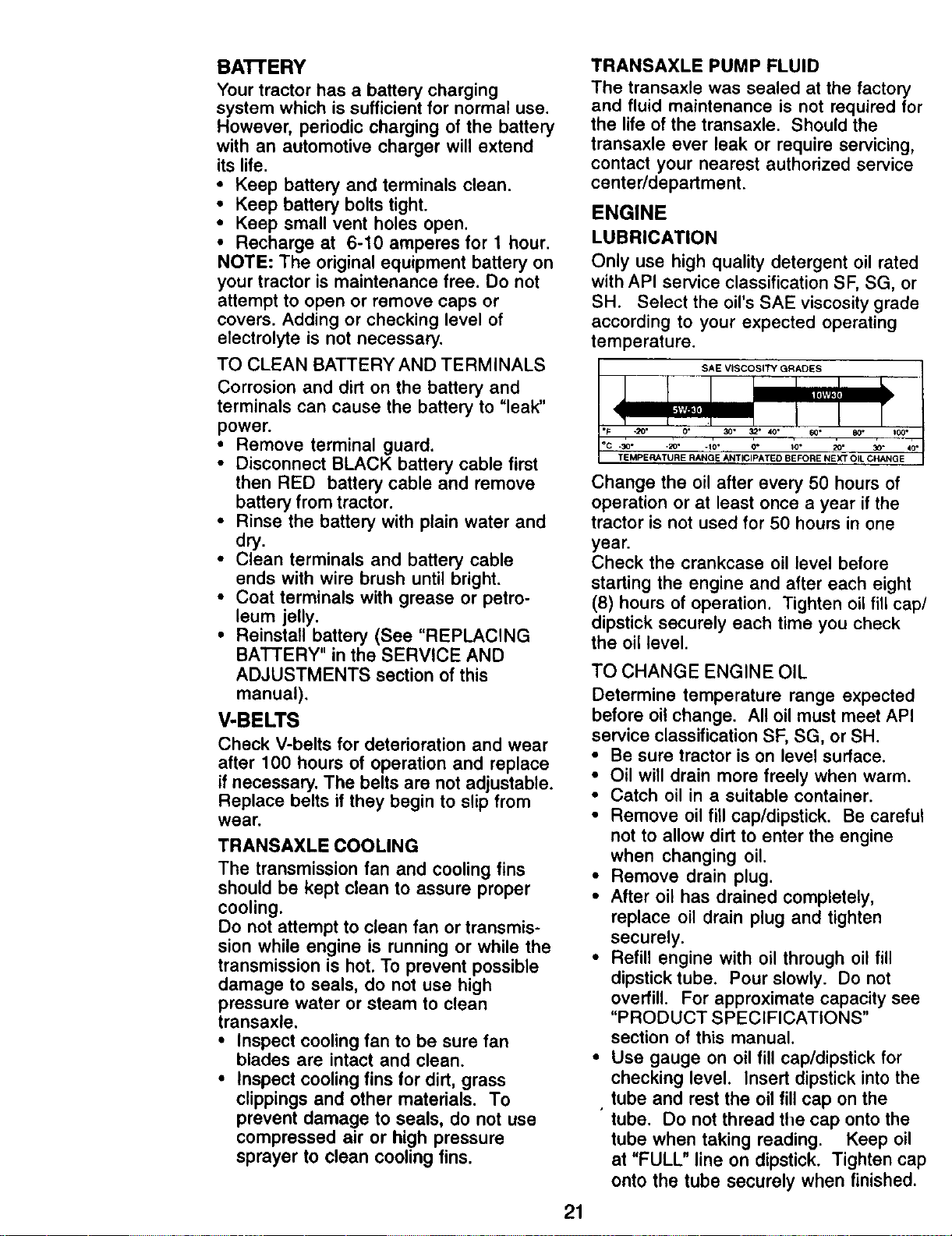
• To check blade balance, you will need
a 5/8" diameter steel bolt, pin, or a
cone balancer. (When using a cone
balancer, follow the instructions
supplied with balancer.)
NOTE- Do not use a nail for balancing
blade. The lobes of the center hole may
appear to be centered, but are not.
• Slide blade on to an unthreaded
portion of the steel bolt or pin and hold
the bolt or pin parallel with the ground.
If blade is balanced, it should remain
in a horizontal position. If either end of
the blade moves downward, sharpen
the heavy end until the blade is
balanced.
5/8" B_d e
Center Hole
20
BAI-FERY
Your tractor has a battery charging
system which is sufficient for normal use.
However, periodic charging of the battery
with an automotive charger will extend
its life.
• Keep battery and terminals clean.
• Keep battery bolts tight.
• Keep small vent holes open,
• Recharge at 6-10 amperes for 1 hour.
NOTE: The original equipment battery on
your tractor is maintenance free. Do not
attempt to open or remove caps or
covers. Adding or checking level of
electrolyte is not necessary.
TO CLEAN BATTERY AND TERMINALS
Corrosion and dirt on the battery and
terminals can cause the battery to "leak"
power.
• Remove terminal guard.
• Disconnect BLACK battery cable first
then RED battery cable and remove
battery from tractor.
• Rinse the battery with plain water and
dry.
• Clean terminals and battery cable
ends with wire brush until bright.
• Coat terminals with grease or petro-
leum jelly.
• Reinstall battery (See "REPLACING
BATTERY" in the SERVICE AND
ADJUSTMENTS section of this
manual).
V-BELTS
Check V-belts for deterioration and wear
after 100 hours of operation and replace
if necessary. The belts are not adjustable.
Replace belts if they begin to slip from
wear.
TRANSAXLE COOLING
The transmission fan and cooling fins
should be kept clean to assure proper
cooling.
Do not attempt to clean fan or transmis-
sion while engine is running or while the
transmission is hot. To prevent possible
damage to seals, do not use high
pressure water or steam to clean
transaxle.
• Inspect cooling fan to be sure fan
blades are intact and clean.
• Inspect cooling fins for dirt, grass
clippings and other materials. To
prevent damage to seals, do not use
compressed air or high pressure
sprayer to clean cooling fins.
TRANSAXLE PUMP FLUID
The transaxle was sealed at the factory
and fluid maintenance is not required for
the life of the transaxle. Should the
transaxle ever leak or require servicing,
contact your nearest authorized service
center/department.
ENGINE
LUBRICATION
Only use high quality detergent oil rated
with API service classification SF, SG, or
SH. Select the oil's SAE viscosity grade
according to your expected operating
temperature.
SAE VISCOSITY GRADES
.2o.
_C =30" 0" 20" 30"
TEMPERATURE RANGE ANTICIPATED BEFORE NEX_TOIL CHANGE
21
Change the oil after every 50 hours of
operation or at least once a year if the
tractor is not used for 50 hours in one
year.
Check the crankcase oil level before
starting the engine and after each eight
(8) hours of operation. Tighten oil fill cap/
dipstick securely each time you check
the oil level.
TO CHANGE ENGINE OIL
Determine temperature range expected
before oil change. All oil must meet API
service classification SF, SG, or SH.
• Be sure tractor is on level surface.
• Oil will drain more freely when warm.
• Catch oil in a suitable container.
• Remove oil fill cap/dipstick. Be careful
not to allow dirt to enter the engine
when changing oil.
• Remove drain plug.
• After oil has drained completely,
replace oil drain plug and tighten
securely.
• Refill engine with oil through oil fill
dipstick tube. Pour slowly. Do not
overfill. For approximate capacity see
"PRODUCT SPECIFICATIONS"
section of this manual.
• Use gauge on oil fill cap/dipstick for
checking level. Insert dipstick into the
tube and rest the oil fill cap on the
tube. Do not thread the cap onto the
tube when taking reading. Keep oil
at "FULL" line on dipstick. Tighten cap
onto the tube securely when finished.
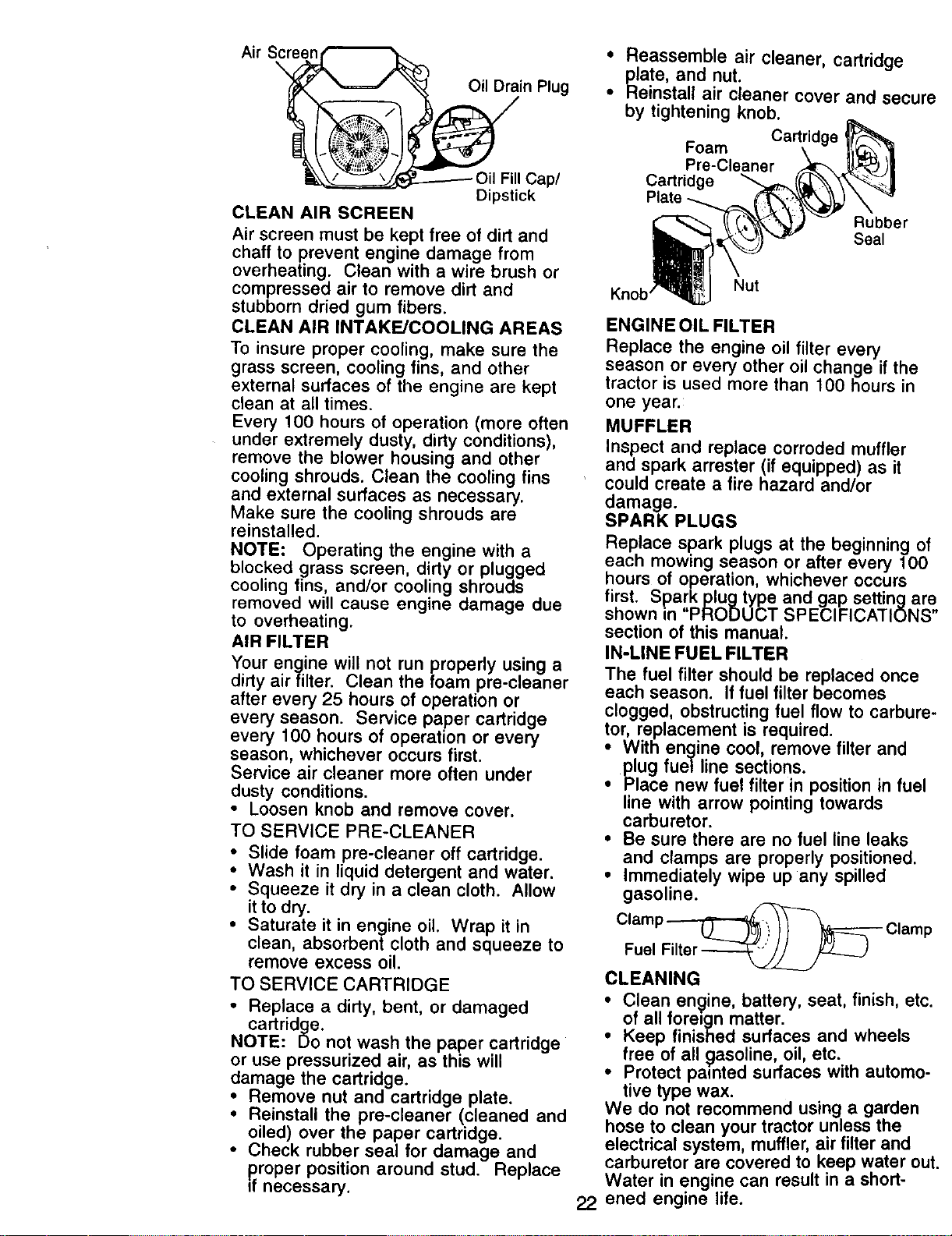
Air Sc_
Oil Drain Plug
_------- Oil FillCap/
Dipstick
CLEAN AIR SCREEN
Air screen must be kept free of dirt and
chaff to prevent engine damage from
overheating. Clean with a wire brush or
compressed air to remove dirt and
stubborn dried gum fibers.
CLEAN AIR INTAKE/COOLING AREAS
To insure proper cooling, make sure the
grass screen, cooling fins, and other
external surfaces of the engine are kept
clean at all times.
Every 100 hours of operation (more often
under extremely dusty, dirty conditions),
remove the blower housing and other
cooling shrouds. Clean the cooling fins
and external surfaces as necessary.
Make sure the cooling shrouds are
reinstalled.
NOTE: Operating the engine with a
blocked grass screen, dirty or plugged
cooling fins, and/or cooling shrouds
removed will cause engine damage due
to overheating.
AIR FILTER
Your engine will not run properly using a
dirty airfilter. Clean the foam pre-cleaner
after every 25 hours of operation or
every season. Service paper cartridge
every 100 hours of operation or every
season, whichever occurs first.
Service air cleaner more often under
dusty conditions.
• Loosen knob and remove cover.
TO SERVICE PRE-CLEANER
• Slide foam pre-cleaner off cartridge.
• Wash it in liquid detergent and water.
• Squeeze it dry in a clean cloth. Allow
it to dry.
• Saturate it in engine oil. Wrap it in
clean, absorbent cloth and squeeze to
remove excess oil.
TO SERVICE CARTRIDGE
• Replace a dirty, bent, or damaged
cartridge.
NOTE: Do not wash the paper cartridge
or use pressurized air, as this will
damage the cartridge.
: Remove nut and cartridge plate.
Reinstall the pre-cleaner (cleaned and
oiled) over the paper cartridge.
• Check rubber seal for damage and
proper position around stud. Replace
ff necessary.
• Reassemble air cleaner, cartridge
plate, and nut.
• Reinstall air cleaner cover and secure
by tightening knob.
Foam
Pre-Cleaner
Cartridge
Plate
Rubber
Seal
22
Knob' Nut
ENGINE OIL FILTER
Replace the engine oil filter every
season or every other oil change if the
tractor is used more than 100 hours in
one year.
MUFFLER
Inspect and replace corroded muffler
and spark arrester (if equipped) as it
could create a fire hazard and/or
damage.
SPARK PLUGS
Replace spark plugs at the beginning of
each mowing season or after every 100
hours of operation, whichever occurs
first. Sparkplugtype and gap setting are
shown in "PRODUCT SPECIFICATIONS"
section of this manual.
IN-LINE FUEL FILTER
The fuel filter should be replaced once
each season. If fuel filter becomes
clogged, obstructing fuel flow to carbure-
tor, replacement is required.
i ith engine cool, remove filter and
plug fuel line sect ons
Place new fuel filter in position in fuel
line with arrow pointing towards
carburetor.
• Be sure there are no fuel line leaks
and clamps are properly positioned.
• Immediately wipe up any spilled
gasoline.
Clamp_ Clamp
Fuel Filter _
CLEANING
• Clean engine, battery, seat, finish, etc.
of all fore=gn matter.
i Keep finished surfaces and wheels
free of all _]asoline, oil, etc.
Protect painted surfaces with automo-
tive type wax.
We do not recommend using a garden
hose to clean your tractor unless the
electrical system, muffler, air filter and
carburetor are covered to keep water out.
Water in engine can result in a short-
ened engine life.
_CAUTION: Before performing any service or adjustments:
• Depress clutch/brake pedal fully and set parking brake.
• Place motion control lever in neutral (N) position.
• Place attachment clutch in "DISENGAGED" position.
• Turn ignition key "OFF" and remove key.
• Make sure the blades and all moving parts have completely stopped.
• Disconnect spark plug wire from spark plug and place wire where it cannot
come in contact with plug.
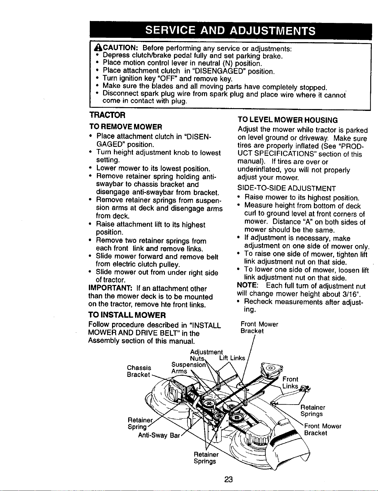
TRACTOR
TO REMOVE MOWER
• Place attachment clutch in "DISEN-
GAGED" position.
• Turn height adjustment knob to lowest
setting.
• Lower mower to its lowest position.
• Remove retainer spring holding anti-
swaybar to chassis bracket and
disengage anti-swaybar from bracket.
• Remove retainer springs from suspen-
sion arms at deck and disengage arms
from deck.
• Raise attachment liftto its highest
position.
• Remove two retainer springs from
each front link and remove links.
• Slide mower forward and remove belt
from electric clutch pulley.
• Slide mower out from under right side
of tractor.
IMPORTANT: If an attachment other
than the mower deck is to be mounted
on the tractor, remove hte front links.
TO INSTALL MOWER
Follow procedure described in "INSTALL
MOWER AND DRIVE BELT" in the
Assembly section of this manual.
TO LEVEL MOWER HOUSING
Adjust the mower while tractor is parked
on level ground or driveway, Make sure
tires are properly inflated (See "PROD-
UCT SPECIFICATIONS" section of this
manual). If tires are over or
underinflated, you will not properly
adjust your mower.
SIDE-TO-SIDE ADJUSTMENT
• Raise mower to its highest position.
• Measure height from bottom of deck
curl to ground level at front corners of
mower. Distance "A" on both sides of
mower should be the same.
• If adjustment is necessary, make
adjustment on one side of mower only.
• To raise one side of mower, tighten lift
link adjustment nut on that side.
• To lower one side of mower, loosen lift
link adjustment nut on that side.
NOTE: Each full turn of adjustment nut
will change mower height about 3/16".
• Recheck measurements alter adjust-
ing.
Front Mower
Bracket
Adjustment
Nuts Lift Links
Chassis
Sus
Retainel
Spring
Anti-Sway Bar,
Retainer
Springs
Mower
Bracket
Retainer
Springs
23
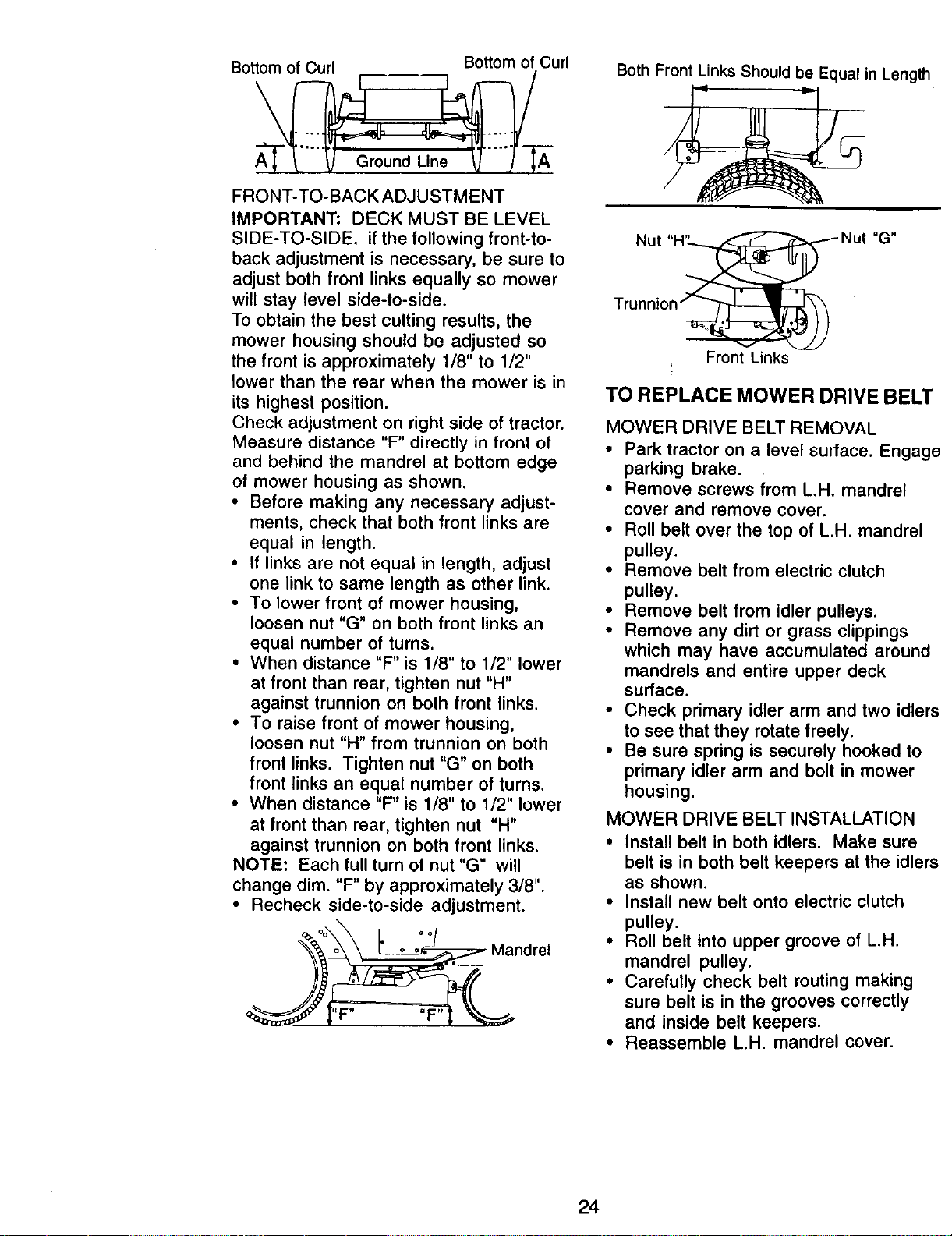
Bottomof Curl Bottom of Curl
FRONT-TO-BACK ADJUSTMENT
IMPORTANT: DECK MUST BE LEVEL
SIDE-TO-SIDE. if the following front-to-
back adjustment is necessary, be sure to
adjust both front links equally so mower
will stay level side-to-side.
To obtain the best cutting results, the
mower housing should be adjusted so
the front is approximately 1/8" to 1/2"
lower than the rear when the mower is in
its highest position.
Check adjustment on right side of tractor.
Measure distance "F" directly in front of
and behind the mandrel at bottom edge
of mower housing as shown.
• Before making any necessary adjust-
ments, check that both front links are
equal in length.
• If links are not equal in length, adjust
one link to same length as other link.
• To lower front of mower housing,
loosen nut "G" on both front links an
equal number of turns.
• When distance "F" is 1/8" to 1/2" lower
at front than rear, tighten nut "H"
against trunnion on both front links.
• To raise front of mower housing,
loosen nut "H" from trunnion on both
front links. Tighten nut "G" on both
front links an equal number of turns.
• When distance "F" is 1/8" to 1/2" lower
at front than rear, tighten nut "H"
against trunnion on both front links.
NOTE; Each full turn of nut "G" will
change dim. "F" by approximately 3/8".
• Recheck side-to-side adjustment.
Both Front Links Should be Equal in Length
Front Links
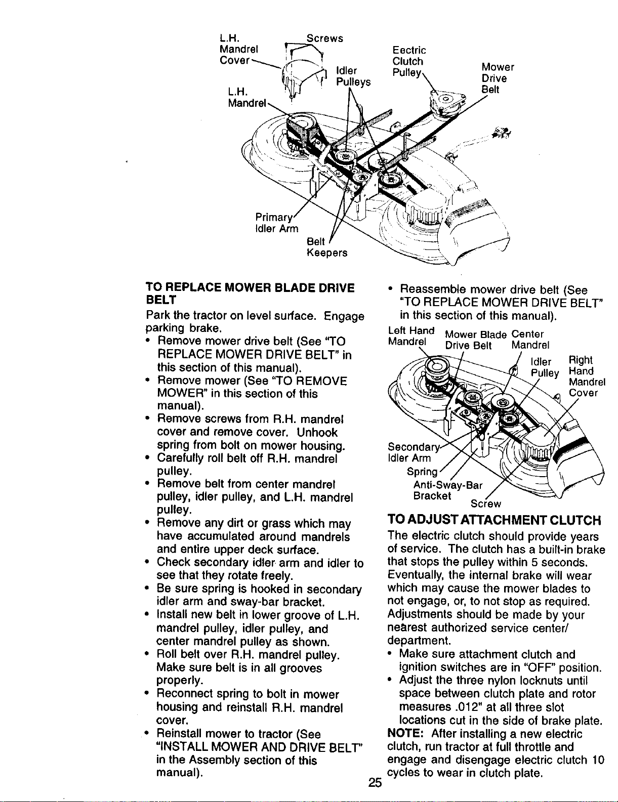
TO REPLACE MOWER DRIVE BELT
MOWER DRIVE BELT REMOVAL
• Park tractor on a level surface. Engage
parking brake.
• Remove screws from LH. mandrel
cover and remove cover.
• Roll belt over the top of L.H. mandrel
pulley.
• Remove belt from electric clutch
pulley.
• Remove belt from idler pulleys.
• Remove any dirt or grass clippings
which may have accumulated around
mandrels and entire upper deck
surface.
• Check primary idler arm and two idlers
to see that they rotate freely.
• Be sure spring is securely hooked to
primary idler arm and bolt in mower
housing.
MOWER DRIVE BELT INSTALLATION
• Install belt in both idlers. Make sure
belt is in both belt keepers at the idlers
as shown.
• Install new belt onto electric clutch
pulley.
• Roll belt into upper groove of L.H.
mandrel pulley.
• Carefully check belt routing making
sure belt is in the grooves correctly
and inside belt keepers.
• Reassemble L.H. mandrel cover.
24
Eectric
Clutch
Mower
Drive
Belt
Idler Arm
Keepers
TO REPLACE MOWER BLADE DRIVE
BELT
Park the tractor on level surface. Engage
parking brake.
• Remove mower drive belt (See "TO
REPLACE MOWER DRIVE BELT" in
this section of this manual).
• Remove mower (See "TO REMOVE
MOWER" in this section of this
manual).
• Remove screws from R.H. mandrel
cover and remove cover. Unhook
spring from bolt on mower housing.
• Carefully roll belt off R.H. mandrel
pulley.
• Remove belt from center mandrel
pulley, idler pulley, and LH. mandrel
pulley.
• Remove any dirt or grass which may
have accumulated around mandrels
and entire upper deck surface.
• Check secondary idler, arm and idler to
see that they rotate freely.
• Be sure spring is hooked in secondary
idler arm and sway-bar bracket.
• Install new belt in lower groove of LH.
mandrel pulley, idler pulley, and
center mandrel pulley as shown.
• Roll belt over R.H. mandrel pulley.
Make sure belt is in all grooves
properly.
• Reconnect spring to bolt in mower
housing and reinstall R.H. mandrel
cover.
• Reinstall mower to tractor (See
"INSTALL MOWER AND DRIVE BELT"
in the Assembly section of this
manual).
• Reassemble mower drive belt (See
"TO REPLACE MOWER DRIVE BELT"
in this section of this manual).
Left Hand Mower Blade Center
Mandrel Drive Belt Mandrel
Idler
Right
Hand
Mandrel
Cover
25
Secondar
Idler Arm
S
Anti-Sway-Bar
Bracket
Screw
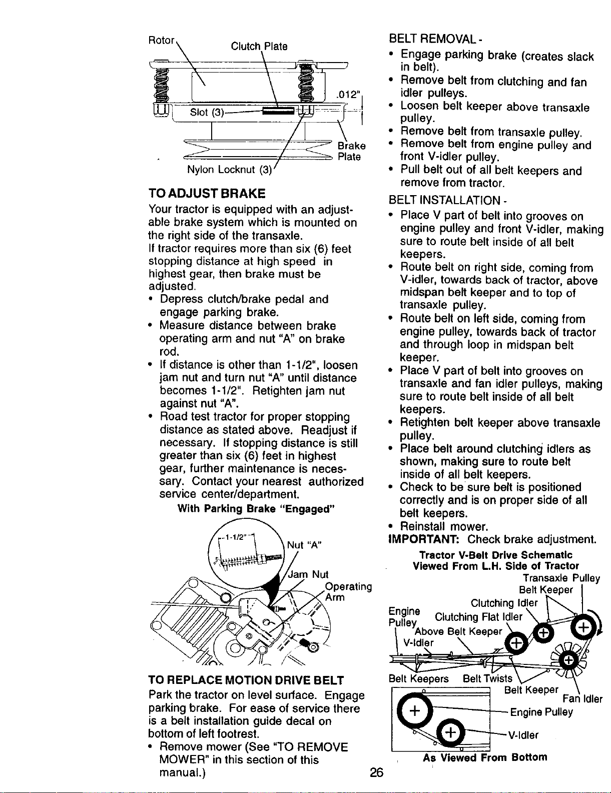
TO ADJUST ATTACHMENT CLUTCH
The electric clutch should provide years
of service. The clutch has a built-in brake
that stops the pulley within 5 seconds.
Eventually, the internal brake will wear
which may cause the mower blades to
not engage, or, to not stop as required.
Adjustments should be made by your
nearest authorized service center/
department.
• Make sure attachment clutch and
ignition switches are in "OFF" position.
• Adjust the three nylon Iocknuts until
space between clutch plate and rotor
measures .012" at all three slot
locations cut in the side of brake plate.
NOTE: After installing a new electric
clutch, run tractor at full throttle and
engage and disengage electric clutch 10
cycles to wear in clutch plate.
r\ Clutch Plate _-_
° Nylon _ (3_ <I Blate
TOADJUSTBRAKE
Your tractor is equipped with an adjust-
able brake system which is mounted on
the right side of the transaxle.
If tractor requires more than six (6) feet
stopping distance at high speed in
highest gear, then brake must be
adjusted.
• Depress clutch/brake pedal and
engage parking brake.
• Measure distance between brake
operating arm and nut "A" on brake
rod.
• If distance is other than 1-1/2", loosen
jam nut and turn nut "A" until distance
becomes 1-1/2". Retighten jam nut
against nut "A"o
• Road test tractor for proper stopping
distance as stated above. Readjust if
necessary. If stopping distance is still
greater than six (6) feet in highest
gear, further maintenance is neces-
sary. Contact your nearest authorized
service center/department.
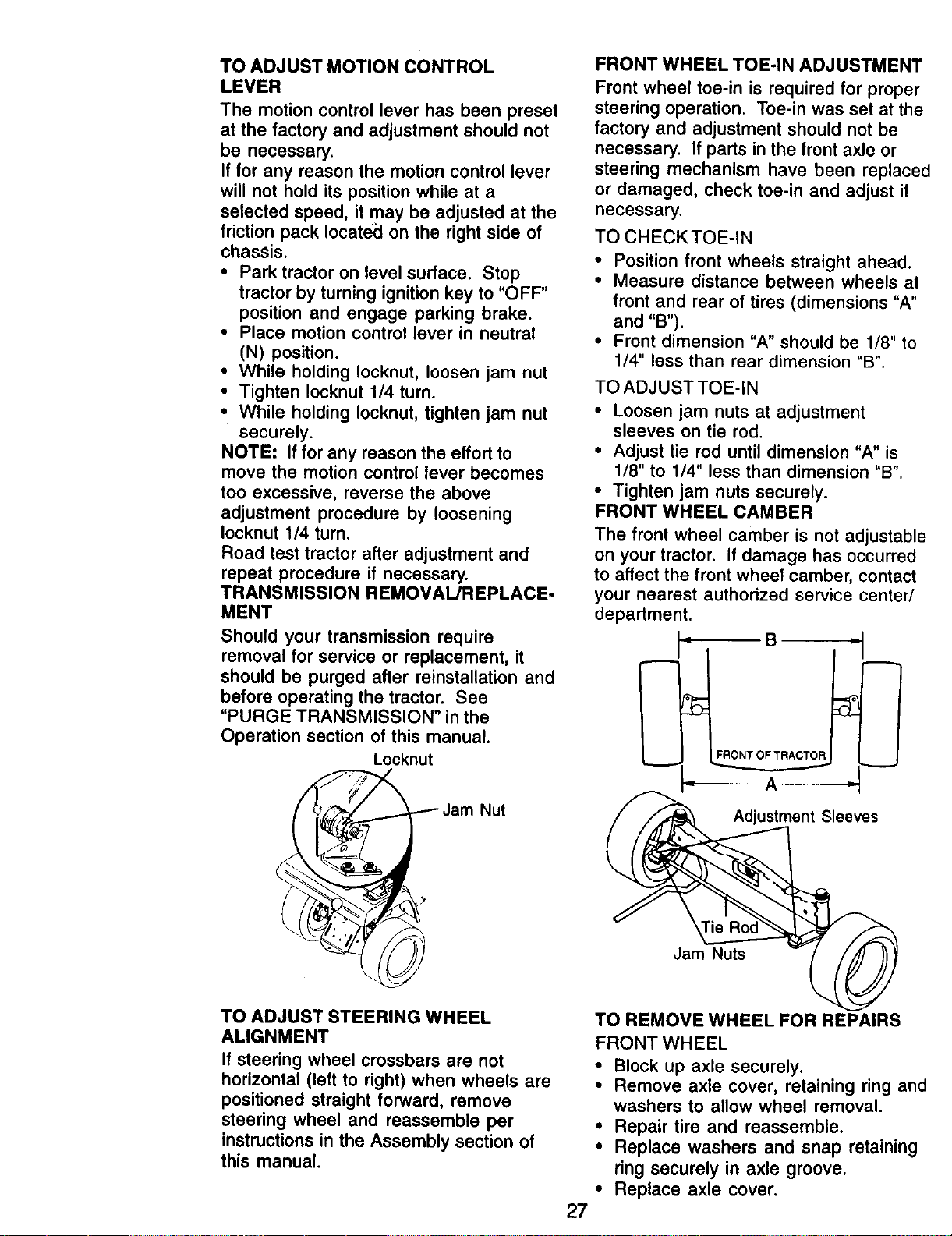
With Parking Brake "Engaged"
Nut "A"
Nut
TO REPLACE MOTION DRIVE BELT
Park the tractor on level surface. Engage
parking brake. For ease of service there
is a belt installation guide decal on
bottom of left footrest.
• Remove mower (See "TO REMOVE
MOWER" in this section of this
manual.)
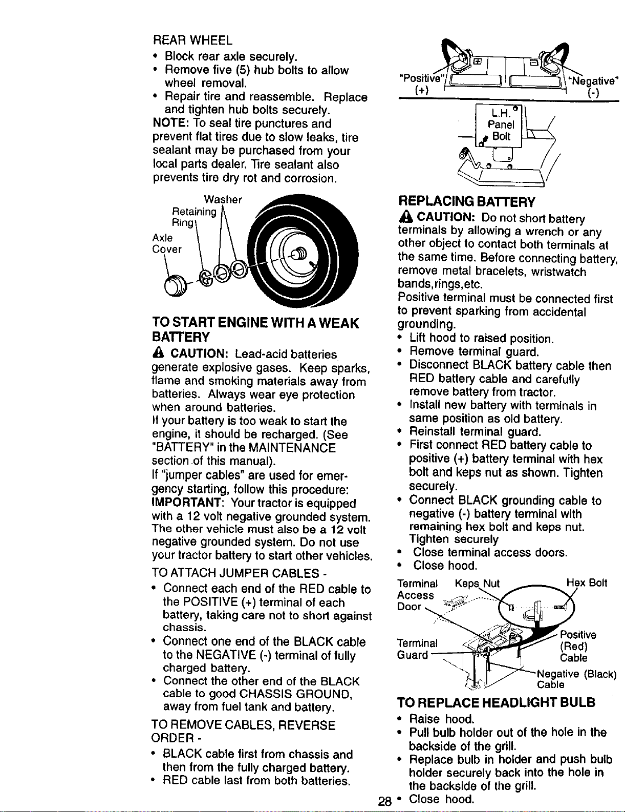
BELT REMOVAL-
• Engage parking brake (creates slack
in belt).
• Remove belt from clutching and fan
idler pulleys.
• Loosen belt keeper above transaxle
pulley.
• Remove belt from transaxle pulley.
• Remove belt from engine pulley and
front V-idler pulley.
• Pull belt out of all belt keepers and
remove from tractor.
BELT INSTALLATION -
• Place V part of belt into grooves on
engine pulley and front V-idler, making
sure to route belt inside of all belt
keepers.
• Route belt on right side, coming from
V-idler, towards back of tractor, above
midspan belt keeper and to top of
transaxle pulley.
• Route belt on left side, coming from
engine pulley, towards back of tractor
and through loop in midspan belt
keeper.
• Place V part of belt into grooves on
transaxle and fan idler pulleys, making
sure to route belt inside of all belt
keepers.
• Retighten belt keeper above transaxle
pulley.
• Place belt around clutching idlers as
shown, making sure to route belt
inside of all belt keepers.
• Check to be sure belt is positioned
correctly and is on proper side of all
belt keepers.
• Reinstall mower.
IMPORTANT: Check brake adjustment.
Tractor VoBelt Drive Schematic
Viewed From L.H. Side of Tractor
Transaxls
Clutching I¢
Eng_e Clutching Flat
YAbove Belt Keeper
V-Idler
26
Belt Keepers Belt Twists
I Belt Keeper
+_[__- Engine Pulley
_,_L_ v- d er
As Viewed From Bottom
TO ADJUST MOTION CONTROL
LEVER
The motion control lever has been preset
at the factory and adjustment should not
be necessary.
If for any reason the motion control lever
will not hold its position while at a
selected speed, it may be adjusted at the
friction pack Iocatecl on the right side of
chassis.
• Park tractor on level surface. Stop
tractor by turning ignition key to "OFF"
position and engage parking brake.
• Place motion control lever in neutral
(N) position.
• While holding Iocknut, loosen jam nut
• Tighten Iocknut 1/4 turn.
• While holding Iocknut, tighten jam nut
securely.
NOTE: If for any reason the effort to
move the motion control lever becomes
too excessive, reverse the above
adjustment procedure by loosening
Iocknut 1/4 turn.
Road test tractor after adjustment and
repeat procedure if necessary.
TRANSMISSION REMOVAL/REPLACE-
MENT
Should your transmission require
removal for service or replacement, it
should be purged after reinstallation and
before operating the tractor. See
"PURGE TRANSMISSION" in the
Operation section of this manual.
Locknut
Jam Nut
FRONT WHEEL TOE-IN ADJUSTMENT
Front wheel toe-in is required for proper
steering operation. Toe-in was set at the
factory and adjustment should not be
necessary. If parts in the front axle or
steering mechanism have been replaced
or damaged, check toe-in and adjust if
necessary.
TO CHECKTOE-IN
• Position front wheels straight ahead.
• Measure distance between wheels at
front and rear of tires (dimensions "A"
and "B").
• Front dimension "A" should be 1/8" to
1/4" less than rear dimension "B".
TO ADJUST TOE-IN
• Loosen jam nuts at adjustment
sleeves on tie rod.
• Adjust tie rod until dimension "A" is
1/8" to 1/4" less than dimension "B".
• Tighten jam nuts securely.
FRONT WHEEL CAMBER
The front wheel camber is not adjustable
on your tractor. If damage has occurred
to affect the front wheel camber, contact
your nearest authorized service center/
department.
P
g _
FRONTOFTRACTOR __
A
Adjustment Sleeves
Jam Nuts
TO ADJUST STEERING WHEEL
ALIGNMENT
If steering wheel crossbars are not
horizontal (left to right) when wheels are
positioned straight forward, remove
steering wheel and reassemble per
instructions in the Assembly section of
this manual.
27
TO REMOVE WHEEL FOR REPAIRS
FRONT WHEEL
• Block up axle securely.
• Remove axle cover, retaining ring and
washers to allow wheel removal.
• Repair tire and reassemble.
• Replace washers and snap retaining
ring securely in axle groove.
• Replace axle cover.
REARWHEEL
• Block rear axle securely.
• Remove five (5) hub bolts to allow
wheel removal.
• Repair tire and reassemble. Replace
and tighten hub bolts securely.
NOTE: To seal tire punctures and
prevent flat tires due to slow leaks, tire
sealant may be purchased from your
local parts dealer. Tire sealant also
prevents tire dry rot and corrosion.
Washer
Retaining
Ring
Axle
Cover
TO START ENGINE WITH A WEAK
BATT'ERY
A CAUTION: Lead-acid batteries
generate explosive gases. Keep sparks,
flame and smoking materials away from
batteries. Always wear eye protection
when around batteries.
If your battery is too weak to start the
engine, it should be recharged. (See
"BATTERY" in the MAINTENANCE
section .of this manual).
If "jumper cables" are used for emer-
gency starting, follow this procedure:
IMPORTANT: Your tractor is equipped
with a 12 volt negative grounded system.
The other vehicle must also be a 12 volt
negative grounded system. Do not use
your tractor battery to start other vehicles.
TO ATTACH JUMPER CABLES -
• Connect each end of the RED cable to
the POSITIVE (+) terminal of each
battery, taking care not to short against
chassis.
• Connect one end of the BLACK cable
to the NEGATIVE (-) terminal of fully
charged battery.
• Connect the other end of the BLACK
cable to good CHASSIS GROUND,
away from fuel tank and battery.
TO REMOVE CABLES, REVERSE
ORDER -
• BLACK cable first from chassis and
then from the fully charged battery.
• RED cable last from both batteries.
"Positi gatlv
(+) r' , ' • 't (.)
REPLACING BATTERY
J_ CAUTION: Do not short battery
terminals by allowing a wrench or any
other object to contact both terminals at
the same time. Before connecting batter
remove metal bracelets, wristwatch
bands,rings,etc.
Positive terminal must be connected firs
to prevent sparking from accidental
grounding.
• Lift hood to raised position.
• Remove terminal guard.
• Disconnect BLACK battery cable ther
RED battery cable and carefully
remove battery from tractor.
• Install new battery with terminals in
same position as old battery.
• Reinstall terminal guard.
• First connect RED battery cable to
positive (+) battery terminal with hex
bolt and keps nut as shown. Tighten
securely.
• Connect BLACK grounding cable to
negative (-) battery terminal with
remaining hex bolt and keps nut.
Tighten securely
• Close terminal access doors.
• Close hood,
Terminal
Access
Door _
Terminal
Hex Bolt
Positive
(Red)
Cable
(Blacl
Cable
TO REPLACE HEADLIGHT BULB
• Raise hood.
• Pull bulb holder out of the hole in the
backside of the grill.
• Replace bulb in holder and push bull
holder securely back into the hole in
the backside of the grill.
28 ° Close hood.
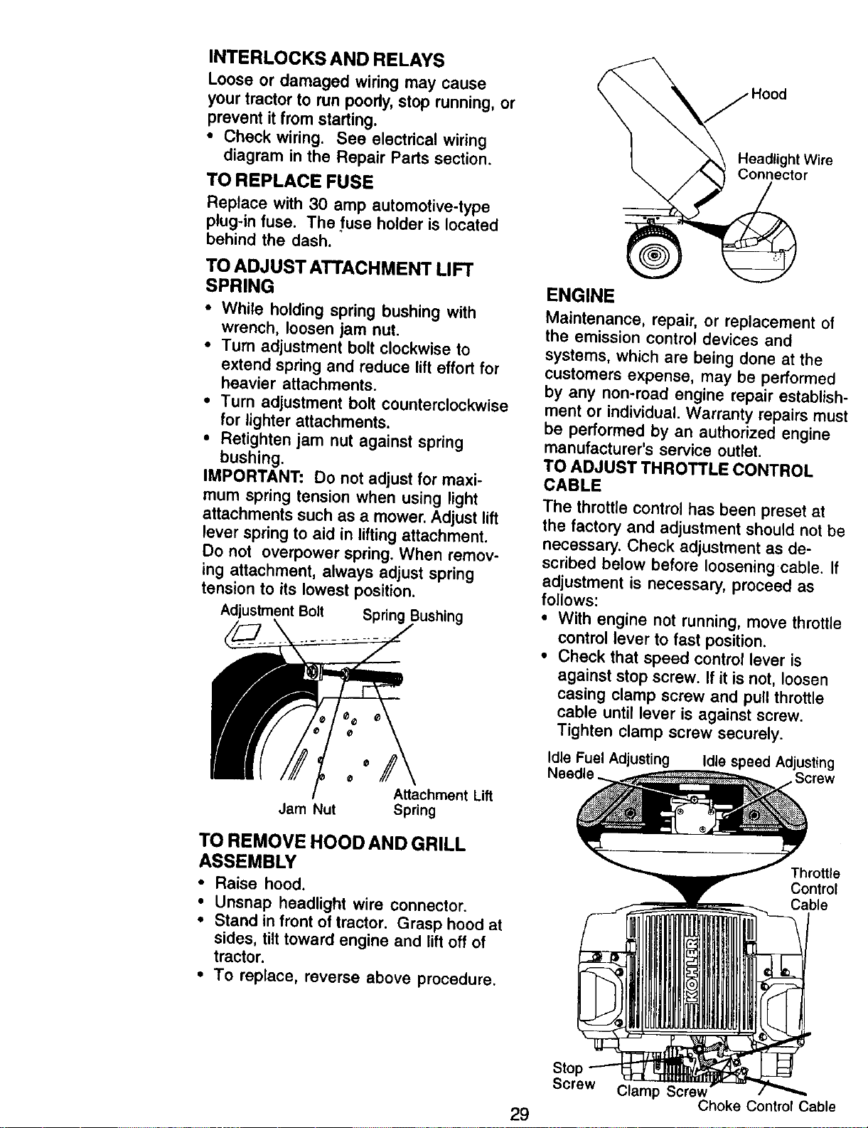
INTERLOCKS AND RELAYS
Loose or damaged wiring may cause
your tractor to run poorly, stop running, or
prevent it from starting.
• Check wiring. See electrical wiring
diagram in the Repair Parts section.
TOREPLACEFUSE
Replace with 30 amp automotive-type
plug-in fuse. The fuse holder is located
behind the dash.
TO ADJUST ATTACHMENT LIFT
SPRING
• While holding spring bushing with
wrench, loosen jam nut.
• Turn adjustment bolt clockwise to
extend spring and reduce lift effort for
heavier attachments.
• Turn adjustment bolt counterclockwise
for lighter attachments.
• Retighten jam nut against spring
bushing.
IMPORTANT: Do not adjust for maxi-
mum spring tension when using light
attachments such as a mower. Adjust lift
lever spring to aid in lifting attachment.
Do not overpower spring. When remov-
ing attachment, always adjust spring
tension to its lowest position.
AdjustmentBolt Spring
Jam Nut
¢
Attachment Lift
Spring
TO REMOVE HOOD AND GRILL
ASSEMBLY
• Raise hood.
• Unsnap headlight wire connector.
• Stand in front of tractor. Grasp hood at
sides, tilt toward engine and tiff off of
tractor.
• To replace, reverse above procedure.
j Hood
Headlight Wire
Connector
ENGINE
Maintenance, repair, or replacement of
the emission control devices and
systems, which are being done at the
customers expense, may be performed
by any non-road engine repair establisl"
ment or individual. Warranty repairs mu.,
be performed by an authorized engine
manufacturer's service outlet.
TO ADJUST THROTTLE CONTROL
CABLE
The throttle control has been preset at
the factory and adjustment should not b_
necessary. Check adjustment as de-
scribed below before loosening cable. If
adjustment is necessary, proceed as
follows:
• With engine not running, move throttle
control lever to fast position.
• Check that speed control lever is
against stop screw. If it is not, loosen
casing clamp screw and pull throttle
cable until lever is against screw.
Tighten clamp screw securely.
Idle Fuel Adjusting Idle speed Adjusting
Screw
Throttle
Control
Cable
Screw Clamp Screw
Choke ControlCable
29
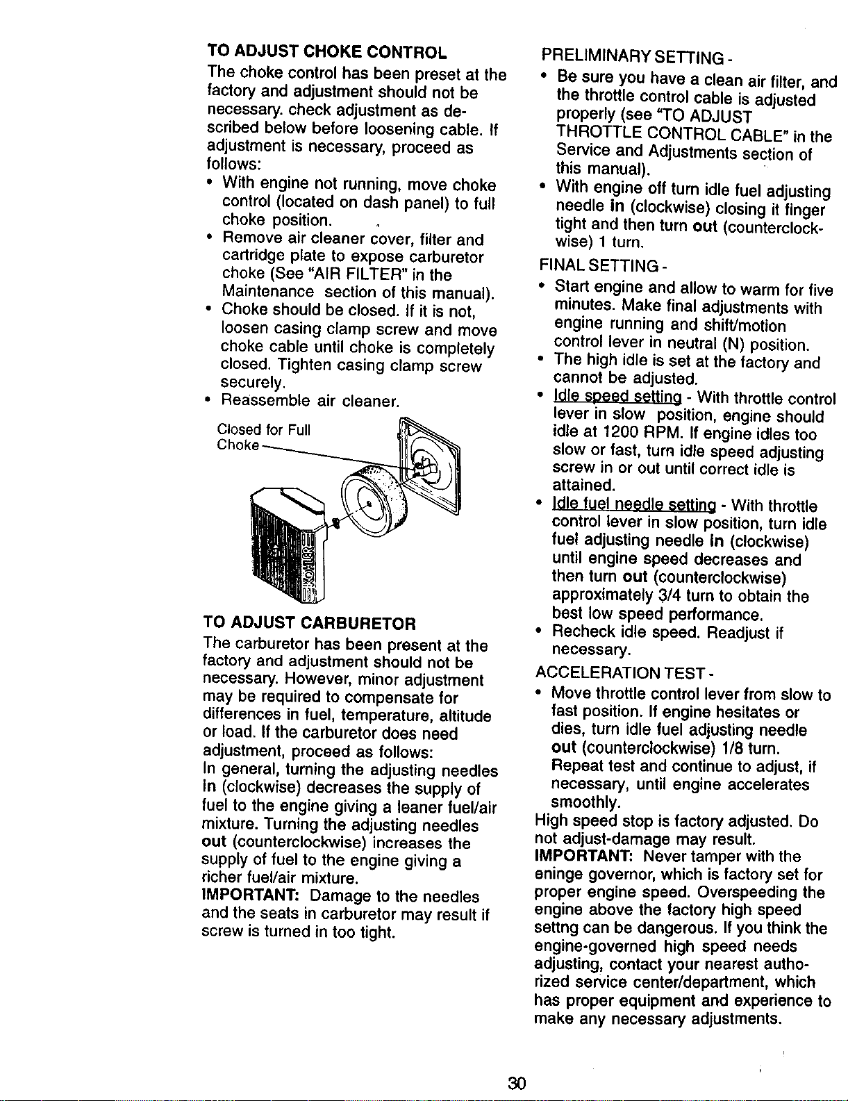
TO ADJUST CHOKECONTROL
The choke control has been preset at the
factory and adjustment should not be
necessary, check adjustment as de-
scribed below before loosening cable, ff
adjustment is necessary, proceed as
follows:
• With engine not running, move choke
control (located on dash panel) to full
choke position.
• Remove air cleaner cover, filter and
cartridge plate to expose carburetor
choke (See "AIR FILTER" in the
Maintenance section of this manual).
• Choke should be closed. If it is not,
loosen casing clamp screw and move
choke cable until choke is completely
closed. Tighten casing clamp screw
securely.
• Reassemble air cleaner.
Closed for Full
TO ADJUST CARBURETOR
The carburetor has been present at the
factory and adjustment should not be
necessary. However, minor adjustment
may be required to compensate for
differences in fuel, temperature, altitude
or load. If the carburetor does need
adjustment, proceed as follows:
In general, turning the adjusting needles
in (clockwise) decreases the supply of
fuel to the engine giving a leaner fuel/air
mixture. Turning the adjusting needles
out (counterclockwise) increases the
supply of fuel to the engine giving a
richer fuel/air mixture.
IMPORTANT: Damage to the needles
and the seats in carburetor may result if
screw is turned in too tight.
PRELIMINARY SETTING -
• Be sure you have a clean air filter, ar
the throttle control cable is adjusted
properly (see "TO ADJUST
THROTTLE CONTROL CABLE" in th
Service and Adjustments section of
this manual).
• With engine off turn idle fuel adjustin
needle in (clockwise) closing it tinge=
tight and then turn out (counterclock-
wise) 1 turn.
FINAL SETTING -
* Start engine and allow to warm for fi\
minutes. Make final adjustments with
engine running and shift/motion
control lever in neutral (N) position.
• The high idle is set at the factory and
cannot be adjusted.
• Idle sbeed setting - With throttle contr
lever in slow position, engine should
idle at 1200 RPM. If engine idles too
slow or fast, turn idle speed adjusting
screw in or out until correct idle is
attained.
• Idle fuel needle setting - With throttle
control lever in slow position, turn idl_
fuel adjusting needle in (clockwise)
until engine speed decreases and
then turn out (counterclockwise)
approximately 3/4 turn to obtain the
best low speed performance.
• Recheck idle speed. Readjust if
necessary.
ACCELERATION TEST -
• Move throttle control lever from slow 1
fast position. If engine hesitates or
dies, turn idle fuel adjusting needle
out (counterclockwise) 1/8 turn.
Repeat test and continue to adjust, if
necessary, until engine accelerates
smoothly.
High speed stop is factory adjusted. Do
not adjust-damage may result.
IMPORTANT" Never tamper with the
eninge governor, which is factory set for
proper engine speed. Overspeeding th_
engine above the factory high speed
settng can be dangerous. If you think thq
engine-governed high speed needs
adjusting, contact your nearest autho-
rized service center/department, which
has proper equipment and experience 1
make any necessary adjustments.
3O
Immediately prepare your tractor for
storage at the end of the season or if the
tractor will not be used for 30 days or
more.
w_itCAUTION: Never store the tractor
h .gasoline in the tank inside a
building where fumes may reach an
open flame or spark. Allow the.engine to
cool before storing in any enclosure.
TRACTOR
Remove mower from tractor for winter
storage. When mower is to be stored for
a penod of time, clean it thoroughly,
remove all dirt, grease, leaves, etc. Store
in a clean, dry area.
• Clean entire tractor (See "CLEANING"
in the Maintenance section of this
manual).
• Inspect and replace belts, if necessary
(See belt replacement instructions in
the Service and Adjustments section of
this manual).
• Lubricate as shown in the Mainte-
nance section of this manual.
• Be sure that all nuts, bolts and screws
are securely fastened. Inspect moving
parts for damage, breakage and wear.
Replace if necessary.
• Touch up all rusted or chipped paint
surfaces; sand lightly before painting.
BATrERY
: Fully charge the battery for storage.
After a period of time in storage,
battery may require recharging.
• To help prevent corrosion and power
leakage during long periods of
storage, battery cables should be
disconnected and battery cleaned
thoroughly (see "TO CLEAN BATTERY
AND TERMINALS" in the Maintenance
section of this manual).
• After cleaning, leave cables discon-
nected and place cables where they
cannot come in contact with battery
terminals.
• If battery is removed from tractor for
storage, do not store battery directly on
concrete or damp surfaces.
ENGINE
FUEL SYSTEM
IMPORTANT: It is important to prevent
_uUmdeposits from forming in essential
el system parts such as carburetor, fuel
filter, fuel hose, or tank during storage.
Also, experience indicates that alcohol
blended fuels 9called gasohol or using
ethanol or methanol) can attract moisture
which leads to separation and formation
of acids during storage. Acidic gas can
damage the fuel system of an engine
while in storage.
• Drain the fuel tank.
• Start the engine and let it run until the
fuel lines and carburetor are empty.
• Never use engine or carburetor
cleaner products in the fuel tank or
permanent damage may occur.
• Use fresh fuel next season.
NOTE: Fuel stabilizer is an acceptable
alternative in minimizing the formation of
fuel gum deposits during storage. Add
stabilizer to gasoline in fuel tank or
storage container. Always follow the mix
ratio found on stabilizer container. Run
engine at least 10 minutes after adding
stabilizer to allow the stabilizer to reach
the carburetor. Do not drain the gas tank
and carburetor if using fuel stabilizer.
ENGINE OIL
Drain oil (with engine warm) and replac_
with clean engine oil. (See "ENGINE" in
the Maintenance section of this manual),
CYLINDER(S)
• Remove spark plug(s).
• Pour one ounce of oil through spark
plug hole(s) into cylinder(s).
• Turn ignition key to "START" position
for a few seconds to distribute oil.
• Replace with new spark plug(s).
OTHER
• Do not store gasoline from one season
to another.
• Replace your gasoline can if your can
starts to rust. Rust and/or dirt in your
gasoline will cause problems.
• If possible, store your tractor indoors
and cover it to give protection from
dust and dirt.
• Cover your tractor with a suitable
protective cover that does not retain
moisture. Do not use plastic. Plastic
cannot breathe which allows conden-
sation to form and will cause your
tractor to rust.
IMPORTANT: Never cover tractor while
engine and exhaust areas are still
warm.
31
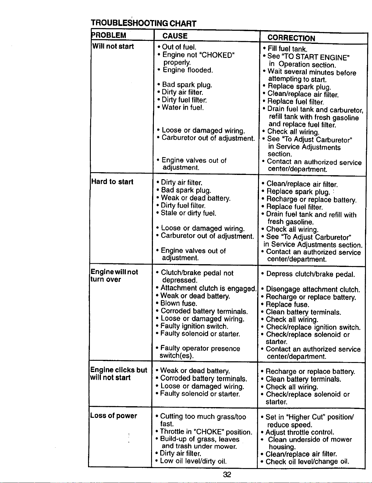
TROUBLESHOOTINGCHART
)ROBLEM
Willnotstad
Hard to start
Engine will not
lurn over
CAUSE
• Out of fuel.
• Engine not "CHOKED"
i
CORRECTION
• Fill fuel tank.
• See "TO START ENGINE"
properly.
• Engine flooded.
• Bad spark plug.
• Dirty air filter.
• Dirty fuel filter.
• Water in fuel.
in Operation section.
• Wait several minutes before
attempting to start.
• Replace spark plug.
• Clean/replace air filter,
• Replace fuel filter.
• Drain fuel tank and carbureto
refill tank with fresh gasoline
and replace fuel filter.
Engine clicks but
will not start
Loss of power
• Loose or damaged wiring.
• Carburetor out of adjustment.
• Engine valves out of
adjustment.
• Dirty air filter.
• Bad spark plug.
• Weak or dead battery.
• Dirty fuel filter.
• Stale or dirty fuel.
• Loose or damaged wiring.
• Carburetor out of adjustment.
• Engine valves out of
adjustment.
• Clutch/brake pedal not
depressed.
• Attachment clutch is engaged.
• Weak or dead battery.
• Blown fuse.
• Corroded battery terminals.
• Loose or damaged wiring.
• Faulty ignition switch,
• Faulty solenoid or starter.
• Faulty operator presence
switch(es).
• Weak or dead battery.
• Corroded battery terminals.
• Loose or damaged wiring.
• Faulty solenoid or starter.
• Cutting too much grass/too
fast.
• Throttle in "CHOKE" position.
• Build-up of grass, leaves
and trash under mower.
• Dirty air filter.
• Low oil level/dirty oil.
32
• Check all wiring.
• See "To Adjust Carburetor"
in Service Adjustments
section,
• Contact an authorized service
center/department.
• Clean/replace air filter.
• Replace spark plug, :
• Recharge or replace battery.
• Replace fuel filter.
• Drain fuel tank and refill with
fresh gasoline.
• Check all wiring.
• See "To Adjust Carburetor"
in Service Adjustments section
• Contact an authorized service
center/department.
I • Depress clutch/brake pedal.
• Disengage attachment clutch.
• Recharge or replace battery.
• Replace fuse.
• Clean battery terminals.
• Check all wiring.
• Check/replace ignition switch.
• Check/replace solenoid or
starter,
• Contact an authorized service
center/department.
• Recharge or replace battery.
• Clean battery terminals.
• Check all wiring.
• Check/replace solenoid or
starter.
• Set in "Higher Cut" position/
reduce speed.
• Adjust throttle control.
• Clean underside of mower
housing.
• Clean/replace air filter.
• Check oil level/change oil.
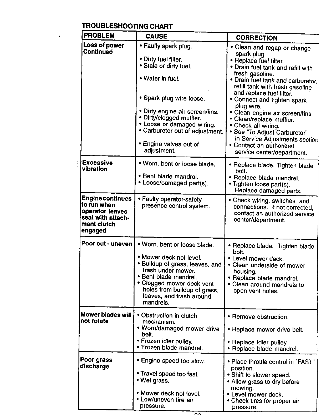
TROUBLESHOOTING CHART
IPROBLEM CAUSE
Loss of power • Faulty spark plug.
Continued
• Dirty fuel filter.
• Stale or dirty fuel.
• Water in fuel,
• Spark plug wire loose,
• Dirty engine air screen/fins.
• Dirty/clogged muffler.
• Loose or damaged wiring.
• Carburetor out of adjustment.
• Engine valves out of
adjustment.
Excessive • Worn, bent or loose blade.
vibration
• Bent blade mandrel.
• Loose/damaged part(s).
Englnecontinuea • Faultyoperator-safety
to run when presence control system.
operator leaves
seat with attach-
ment clutch
engaged
Poor cut - uneven • Worn, bent or loose blade.
• Mower deck not level.
• Buildup of grass, leaves, and
trash under mower.
• Bent blade mandrel.
• Clogged mower deck vent
holes from buildup of grass,
leaves, and trash around
mandrels.
Mower blades will • Obstruction in clutch
not rotate mechanism,
• Worn/damaged mower drive
belt.
• Frozen idler pulley.
• Frozen blade mandrel.
Poor grass • Engine speed too slow.
discharge
• Travel speed too fast.
• Wet grass.
• Mower deck not level.
• Low/uneven tire air
pressure.
CORRECTION
• Clean and regap or change
spark plug.
• Replace fuel filter,
• Drain fuel tank and refill with
fresh gasoline.
• Drain fuel tank and carbureto
refill tank with fresh gasoline
and replace fuel filter.
• Connect and tighten spark
plug wire.
• Clean engine air screen/fins.
• Clean/replace muffler.
• Check all wiring.
• See "To Adjust Carburetor"
in Service Adjustments sectic
• Contact an authorized
service center/department.
• Replace blade. Tighten blade
bolt.
• Replace blade mandrel.
• Tighten loose part(s),
Replace damaged parts.
• Check wiring, switches and
connections. If not corrected,
contact an authorized service
canter/department.
• Replace blade. Tighten blade
bolt.
• Level mower deck.
• Clean underside of mower
housing.
• Replace blade mandrel.
• Clean around mandrels to
open vent holes.
• Remove obstruction.
• Replace mower drive belt.
• Replace idler pulley.
• Replace blade mandrel.
• Place throttle control in "FAST"
position.
• Shift to slower speed,
• Allow grass to dry before
mowing.
• Level mower deck,
• Check tires for proper air
pressure.
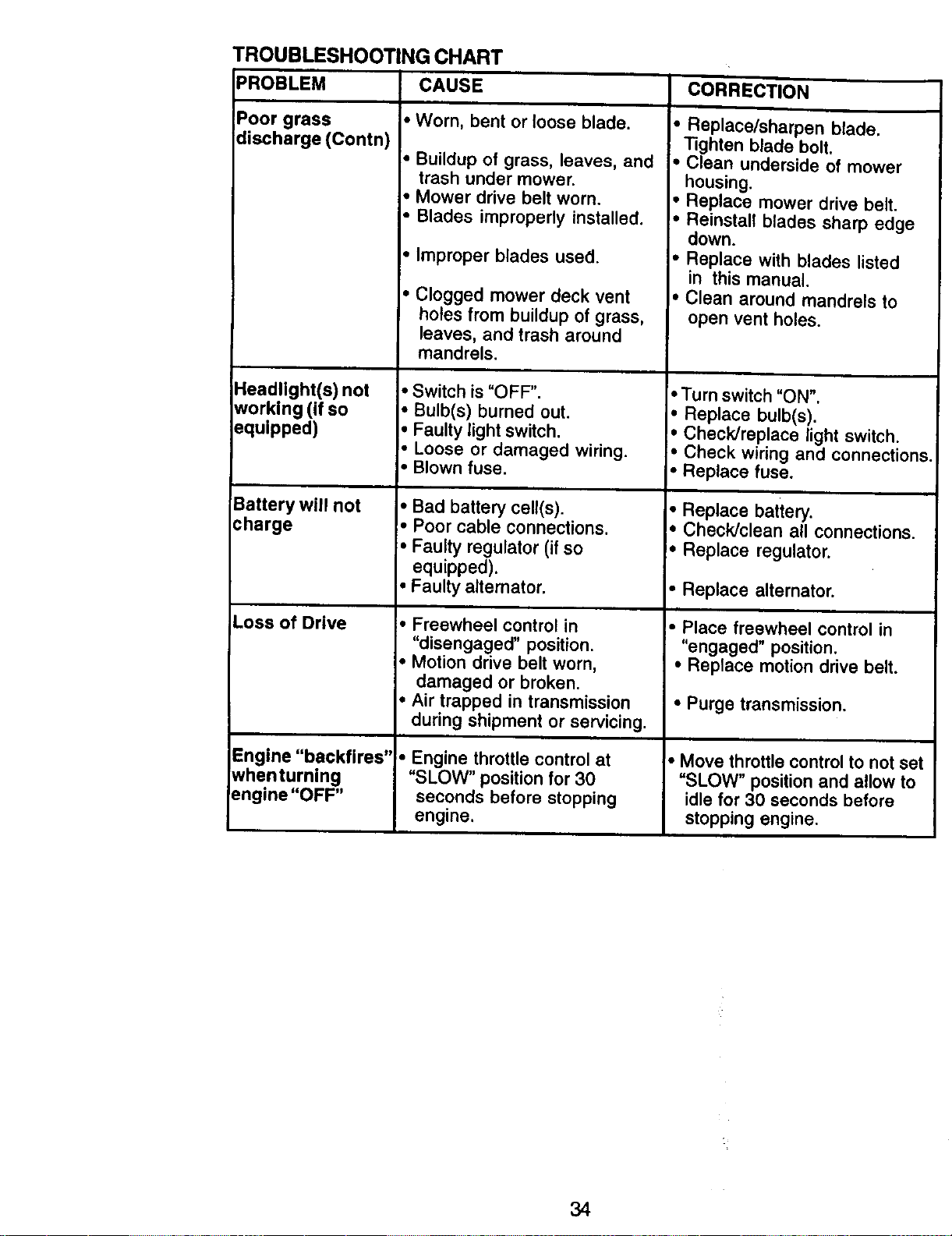
TROUBLESHOOTING CHART
PROBLEM CAUSE CORRECTION
Poor grass
discharge (Contn)
Headlight(s) not
working (if so
equipped)
Battery will not
charge
Loss of Drive
Engine "backfires"
whenturning
engine "OFF"
• Worn, bent or loose blade.
• Buildup of grass, leaves, and
trash under mower.
• Mower drive belt worn.
• Blades improperly installed.
• Improper blades used.
• Clogged mower deck vent
holes from buildup of grass,
leaves, and trash around
mandrels.
• Switch is "OFF".
• Bulb(s) burned out.
• Faulty light switch.
• Loose or damaged wiring.
• Blown fuse.
• Bad battery cell(s).
• Poor cable connections.
• Faulty regulator (if so
equipped).
• Faulty alternator,
• Freewheel control in
"disengaged" position.
• Motion drive belt worn,
damaged or broken.
• Air trapped in transmission
during shipment or servicing.
• Engine throttle control at
"SLOW" position for 30
seconds before stopping
engine.
• Replace/sharpen blade.
Tighten blade bolt.
• Clean underside of mower
housing.
• Replace mower drive belt.
• Reinstall blades sharp edge
down.
• Replace with blades listed
in this manual.
. Clean around mandrels to
open vent holes.
• Turn switch "ON".
• Replace bulb(s).
• Check/replace light switch.
• Check wiring and connection=
• Replace fuse.
• Replace battery.
• Check/clean all connections.
• Replace regulator,
• Replace alternator,
• Place freewheel control in
"engaged" position.
• Replace motion drive belt.
• Purge transmission.
I. Move throttle control to not set
=SLOW" position and allow to
idle for 30 seconds before
stopping engine.
34
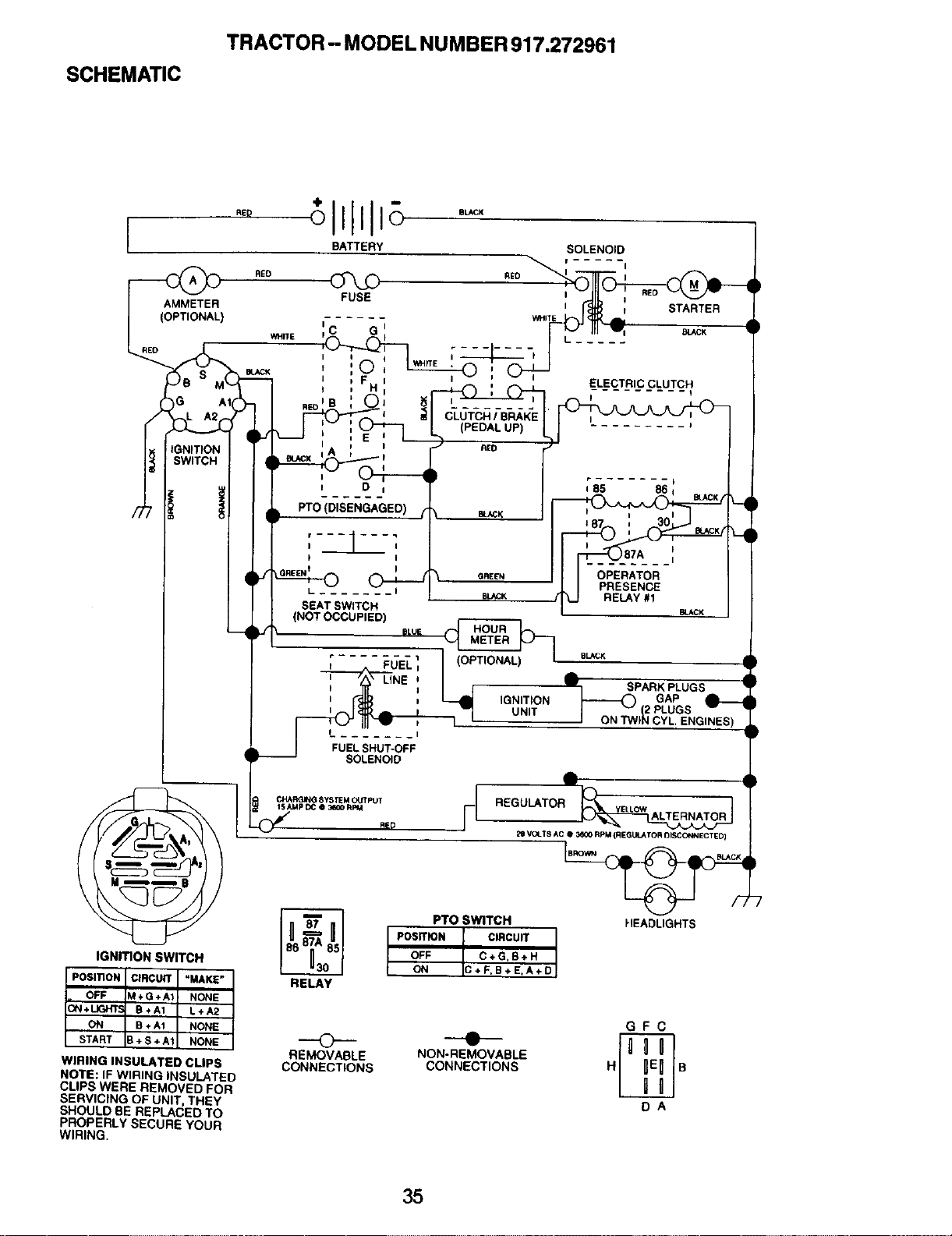
SCHEMATIC
TRACTOR -- MODEL NUMBER 917.272961
)G A1I
|GN}T_ON
SWITCH
IGNmON SWITCH
WIRING INSULATED CLIPS
NOTE: IF WIRING INSULATED
CLIPS WERE REMOVED FOR
SERVICING OF UNIT, THEY
SHOULD BE REPLACED TO
PROPERLY SECURE YOUR
WIRING.
D i
PTO (DISENGAGED) i,"
I I
L -I
FUEL SHUT-OFF
SOLENOIO
iGNITiON
UNIT
A
R_ _ VO__T$ A C 0 3_00 RpM (REGUtJ_TOR DISCONNECT ED)
I PTO SWITCH HEADLIGHTS
POSITION CIRCUIT
OFF C÷G,B+H
ON C+F,B+E,A+D
RELAY
GFC
o -.-
REMOVABLE NON-REMOVABLE
CONNECTIONS CONNECTIONS H B
DA
35
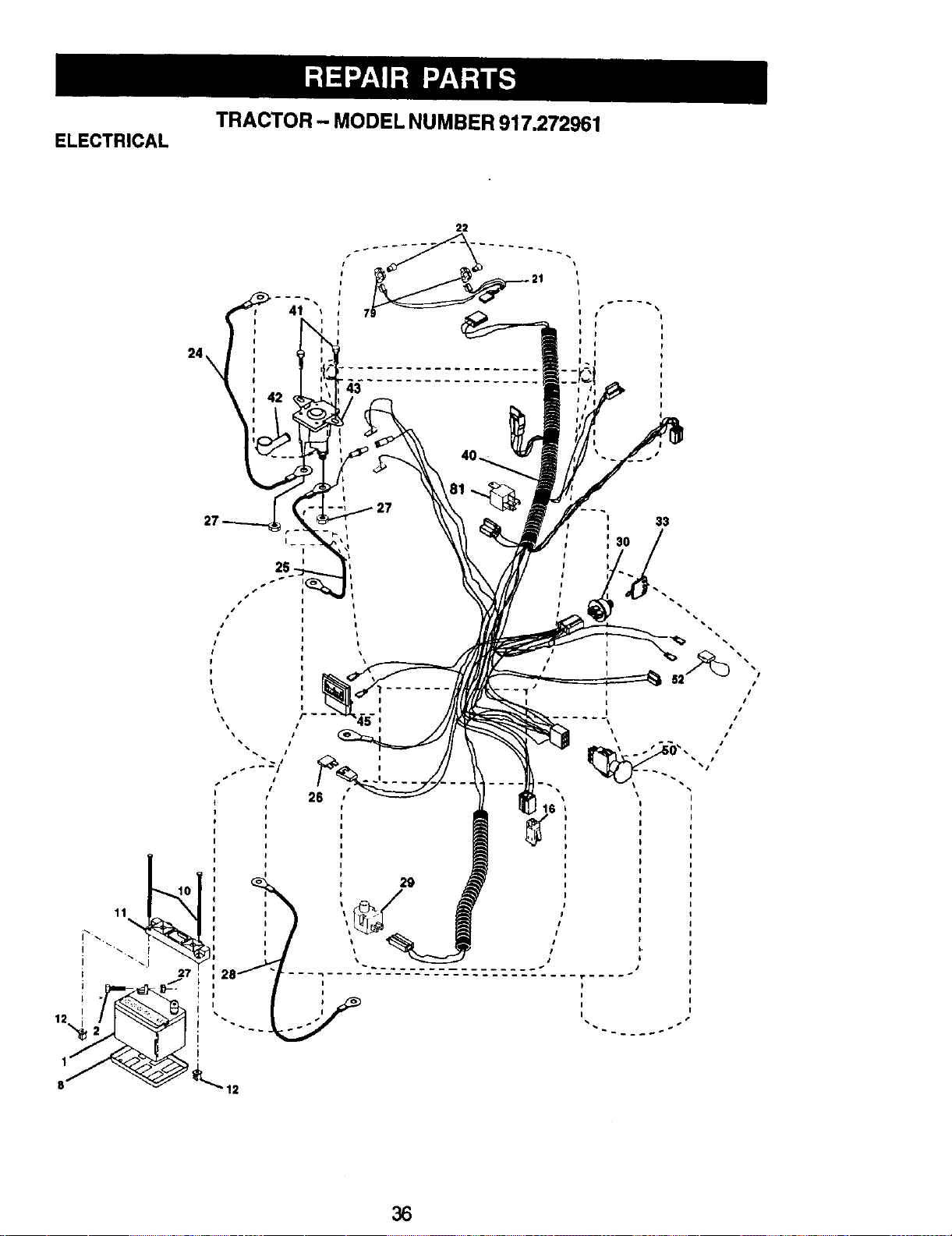
TRACTOR - MODEL NUMBER 917.272961
ELECTRICAL
41
I
43
22
27
33
I
I
I i
36
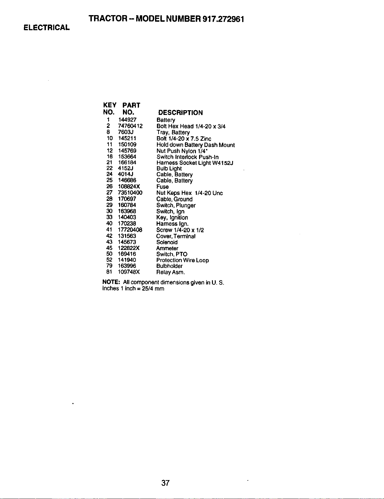
ELECTRICAL
TRACTOR- MODEL NUMBER 917.272961
KEY PART
NO. NO. DESCRIPTION
1 144927 Battery
2 74760412 Bolt Hex Head 1/4-20 x 3/4
8 7603J Tray, Battery
10 145211 Bolt 1/4-20 x 7.5 Zinc
11 150109 Hold down Battery Dash Mount
12 145769 Nut Push Nylon 1/4"
16 153664 Switch Interlock Push-In
21 166184 Harness Socket Light W4152J
22 4152J Bulb Light
24 4014J Cable, Battery
25 146686 Cable, Battery
26 108824X Fuse
27 73510400 Nut Keps Hex 1/4-20 Unc
28 170697 Cable, Ground
29 160784 Switch, Plunger
30 163968 Switch, Ign
33 140403 Key, Ignition
40 170238 Harness Ign,
41 17720408 Screw 1/4-20 x 1/2
42 131563 Cover, Terminal
43 145673 Solenoid
45 122822X Ammeter
50 169416 Switch, PTO
52 141940 Protection Wire Loop
79 163996 Bulbholder
81 109748X Retay Asm.
NOTE: AllcomponentdimensionsgiveninU. S.
inches1 inch= 25/4 mm
37
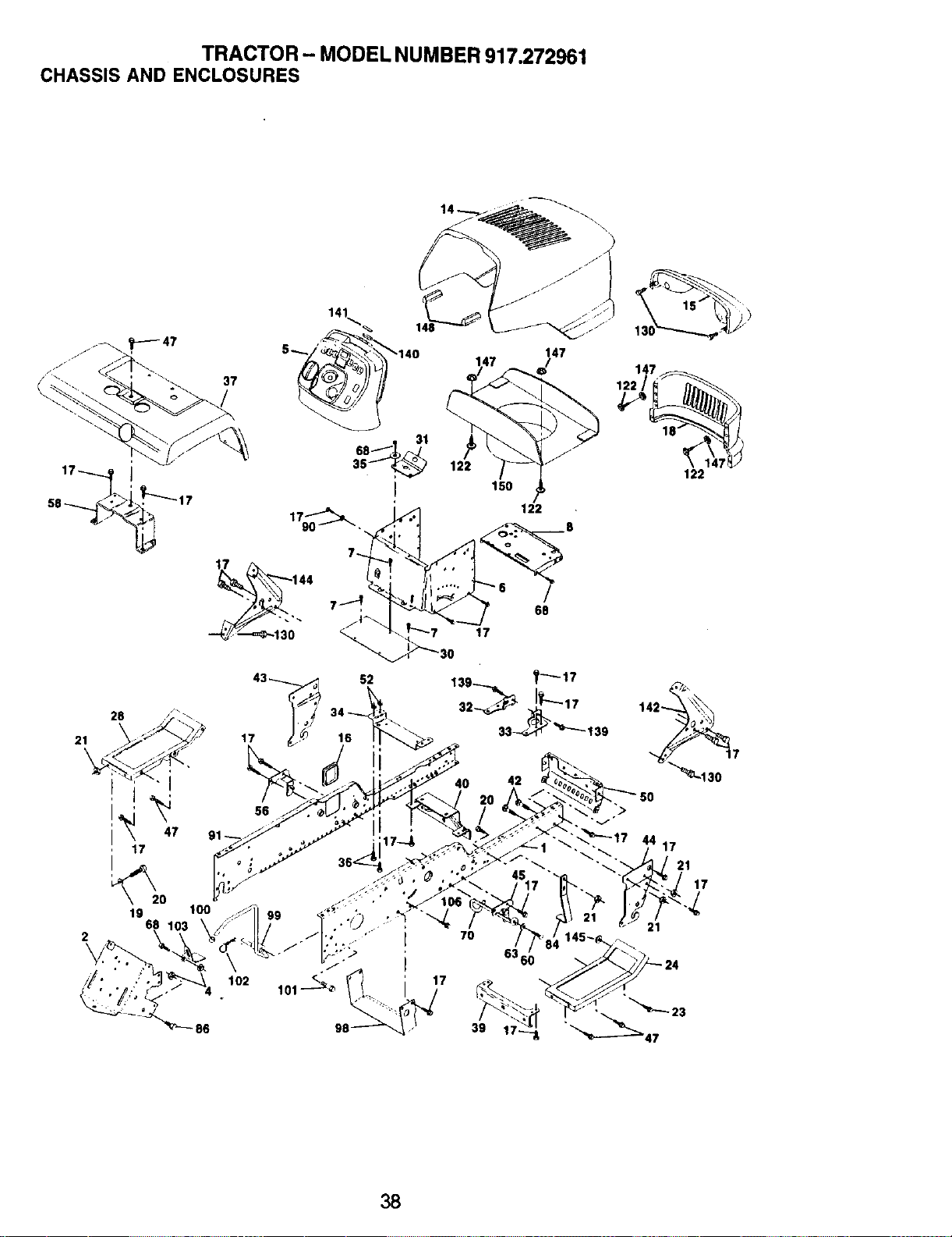
TRACTOR - MODEL NUMBER 917.272961
CHASSIS AND ENCLOSURES
i i
I 47
17
19
68
2
37
147
122
150
I[_ 68
_i_30 17
43_ 52
17 16
86
56
102
7O
17
39
42
38
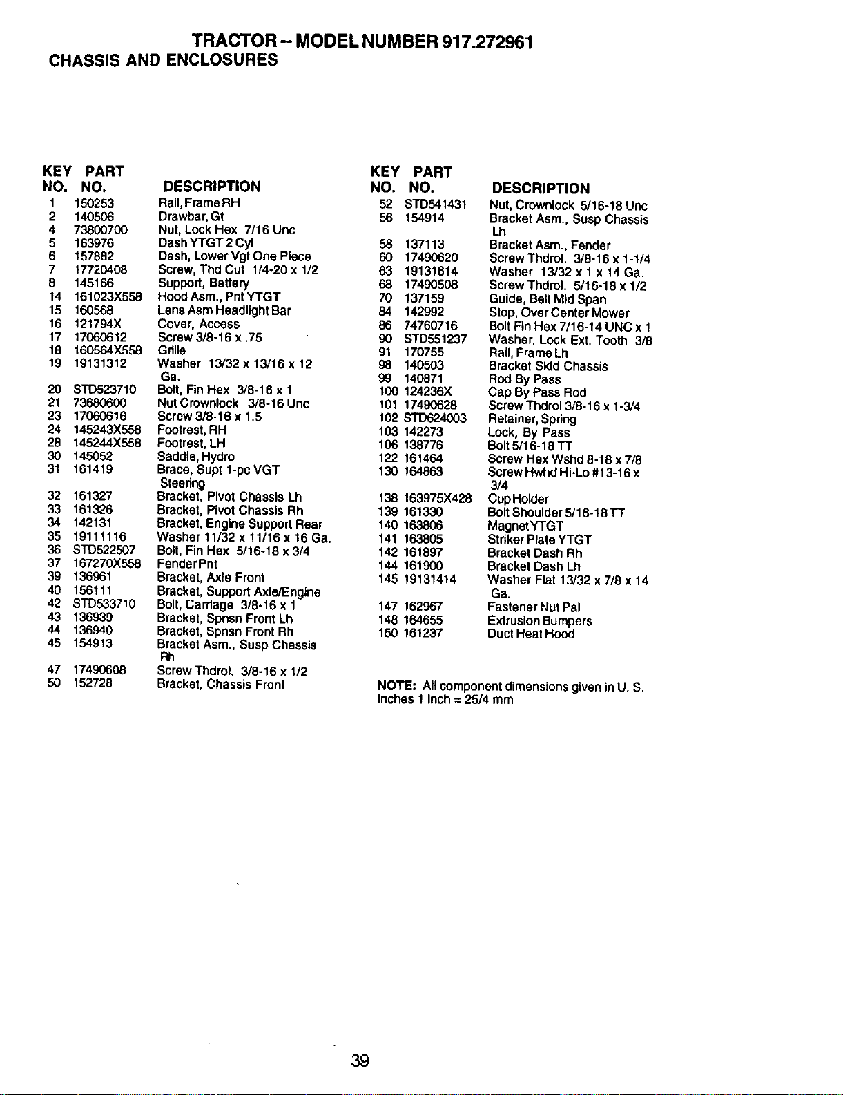
TRACTOR- MODEL NUMBER 917.272961
CHASSIS AND ENCLOSURES
KEY PART KEY PART
NO. NO. DESCRIPTION NO. NO.
1 150253 Rail,Frame RH 52 STD541431
2 140506 Drawbar, Gt 56 154914
4 73800700 Nut, Lock Hex 7/16 Unc
5 163976 Dash YTGT 2 Cyl 58 137113
6 157882 Dash, Lower Vgt One Piece 60 17490620
7 17720408 Screw, Thd Cut 1/4-20 x 1/2 63 19131614
8 145166 Support, Battery 68 17490508
14 161023X558 HoodAsm.,PntYTGT 70 137159
15 160568 LensAsmHeadlightBar 84 142992
16 121794X Cover, Access 86 74760716
17 17060612 Screw3/8-16 x.75 90 STD551237
18 160564X558 Gnlla 91 170755
19 19131312 Washer 13/32 x 13116 x 12 98 140503
Ga. 99 140871
20 STD523710 Bolt, Fin Hex 3/8-16 x I 100 124236X
21 73680600 NutCrownlock 3/8-16Unc 101 17490628
23 17060616 Screw 3/8-16 x 1.5 102 STD624(X)3
24 145243X558 Footrest, RH 103 142273
28 145244X558 Footrest, LH 106 138776
30 145052 Saddle, Hydro 122 161464
31 161419 Brace, Supt 1-pc VGT 130 164863
Steering
32 161327 Bracket, Pivot Chassis Lh 138 163975X428
33 161326 Bracket, Pivot Chassis Rh 139 161330
34 142131 Bracket, Engine Support Rear 140 163806
35 19111116 Washer11/32 x11/16 x16 Ga. 141 163805
36 STD522507 Bolt, Fin Hex 5/16-18 x 3/4 142 161897
37 167270X558 FenderPnt 144 161900
39 136961 Bracket, Axte Front 145 19131414
40 156111 Bracket, Support Axle/Engine
42 STD533710 Bolt, Carriage 3/8-16 x 1 147 162967
43 136939 Bracket, Spnsn Front Lh 148 164655
44 136940 Bracket, Spnsn Front Rh 150 161237
45 154913 Bracket Asm., Susp Chassis
F_
47 17490608 ScrewThdroL 3/8-16 x 1/2
50 152728 Bracket, Chassis Front
DESCRIPTION
Nut, Crownlook 5/16-18 Unc
Bracket Asm., Susp Chassis
I.h
Bracket Asm., Fender
Screw Thdrol. 3/8-16 x 1-1/4
Washer 13/32 x 1 x 14 Ga.
Screw Thdrol. 5/16-18 x 1/2
Guide, Belt Mid Span
Stop, Over Center Mower
Bolt Fin Hex 7/16-14 UNC x 1
Washer, Lock Ext. Tooth 3/8
Rail, Frame Lh
Bracket Skid Chassis
Rod By Pass
Cap By Pass Rod
Screw Thdrol 3/8-16 x 1-3/4
Retainer, Spring
Lock, By Pass
Bolt 5/16-18 TT
Screw Hex Wshd 8-18 x 7/8
Screw Hwhd Hi-Lo #13-16 x
3/4
Cup Holder
Bolt Shoulder 5/16-18 TT
MagnetYTGT
Striker Plate YTGT
Bracket Dash Rh
Bracket Dash Lh
Washer Flat 13/32 x 7/8 x 14
Ga.
Fastener Nut Pal
Extrusion Bumpers
Duct Heat Hood
NOTE: All component dimensions given in U. S.
inches 1 inch = 25/4 mm
39
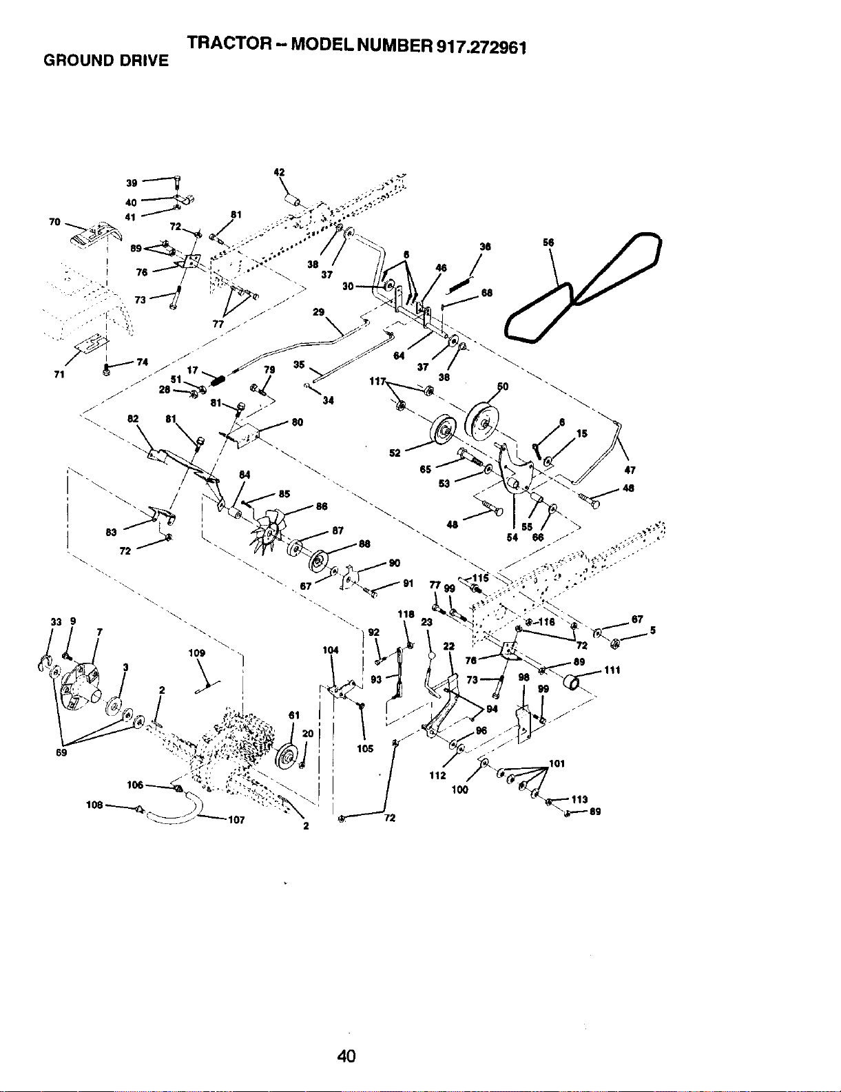
TRACTOR - MODEL NUMBER 917.272961
GROUND DRIVE
33 9
69
i 112 100
IOl
4O
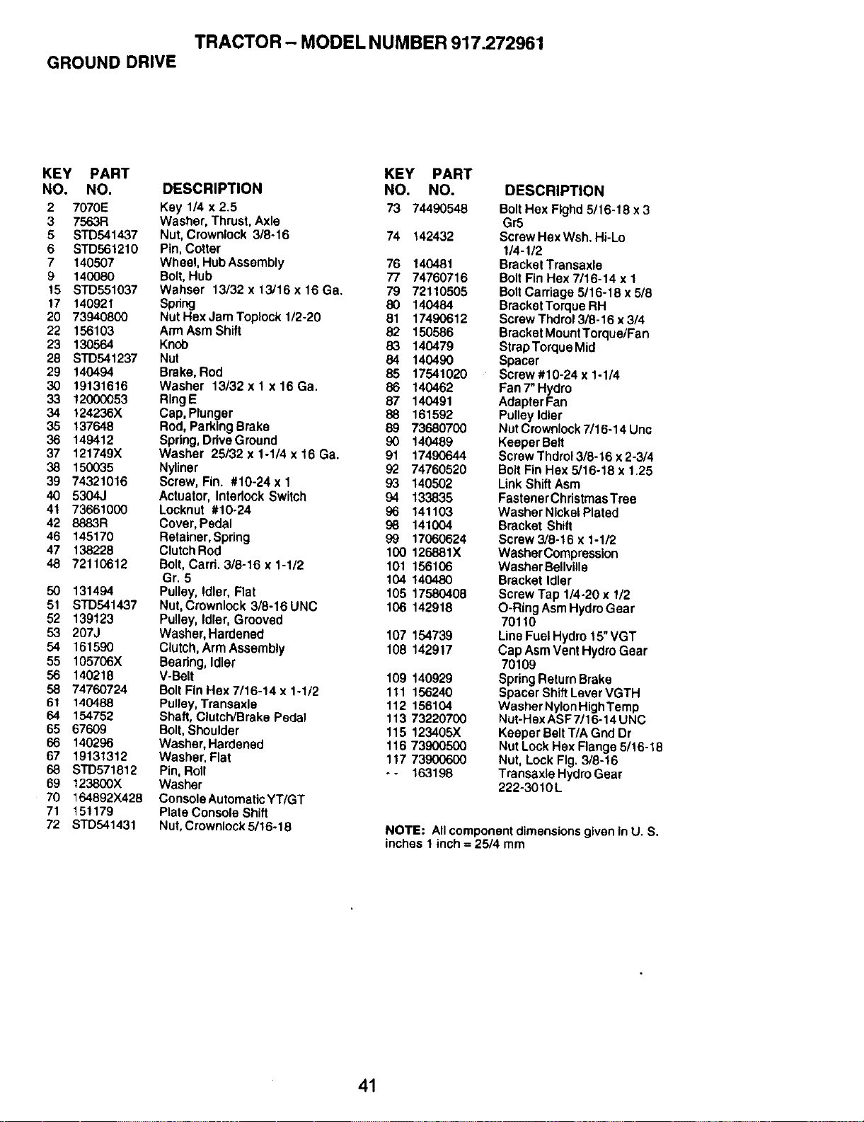
TRACTOR - MODEL NUMBER 917.272961
GROUND DRIVE
KEY PART KEY PART
NO. NO. DESCRIPTION NO. NO.
2 7070E Key 1/4 x 2.5 73 74490548
3 7563R Washer, Thrust, Axle
5 STD541437 Nut, Crownlock 3/8-16 74 142432
6 STD561210 Pin, Cotter
7 140507 WheeI, Hub Assembly 76 140481
9 140080 Bolt, Hub 77 74760716
15 STD551037 Wahser 13/32 x 13/16 x 16 Ga. 79 72110505
17 140921 Spring 80 140484
20 73940800 NutHexJamToplockl/2-20 81 17490612
22 156103 Arm Asm Shift 82 150586
23 130564 Knob 83 140479
28 STD541237 Nut 84 140490
29 140494 Brake, Rod 85 17541020
30 19131616 Washer 13/32 x 1 x 16 Ga. 86 140462
33 12000053 RingE 87 140491
34 124236X Cap, Plunger 88 161592
35 137648 Rod, Parking Brake 89 73680700
36 149412 Spdng, DriveGround 90 140489
37 121749X Washer 25/32 x 1-1/4 x 16 Ga. 91 17490644
38 150035 Nyliner 92 74760520
39 74321016 Screw, Fin. #10-24x 1 93 140502
40 5304J Actuator, Interlock Switch 94 133835
41 73661000 Locknut #10-24 96 141103
42 8883R Cover, Pedal 98 141004
46 145170 Retainer, Spring 99 17060624
47 138228 ClutchRod 100 126881X
48 72110612 Bolt, Card. 3/8-16 x 1-1/2 101 156108
Gr. 5 104 140480
50 131494 Pulley, Idler, Flat 105 17580408
51 STD541437 Nut, Crownlock 3/8-16UNC 106 142918
52 139123 Pulley, Idler, Grooved
53 207J Washer, Hardened 107 154739
54 161590 Clutch, Arm Assembly 108 142917
55 105706X Beadng, Idler
56 140218 V-Belt 109 140929
58 74760724 Bolt Fin Hex 7/16-14 x 1-1/2 111 156240
61 140488 Pulley, Transaxle 112 156104
64 154752 Shaft, Clutch/Brake Pedal 113 73220700
65 67609 Bolt, Shoulder 115 123405X
66 140296 Washer, Hardened 116 73900500
67 19131312 Washer, Flat 117 73900600
STD571812 Pin, Roll - - 163198
69 123800X Washer
70 164892X428 ConsoleAutomattcYT/GT
71 15t 179 Plate Console Shift
72 STD541431 Nut, Crownlock 5/16-18
DESCRIPTION
Bolt Hex Flghd 5/16-18 x 3
Gr5
Screw Hex Wsh. Hi-Lo
1/4-1/2
Bracket Transaxle
Bolt Fin Hex 7/16-14 x 1
BoltCarriage 5/16-18 x 5/8
Bracket Torque RH
Screw Thdrol 3/8-16 x 3/4
Bracket Mount Torque/Fan
Strap Torque Mid
Spacer
Screw #10-24 x 1-1/4
Fan 7" Hydro
Adapter Fan
Pulley Idler
Nut Crownlock 7/16-14 Unc
Keeper Belt
Screw Thdrol 3/8-16 x2-3/4
Bolt Fin Hex 5/16-18 x 1.25
Link Shift Asm
Fastener Christmas Tree
Washer Nickel Plated
Bracket Shift
Screw 3/8-16 x 1-1/2
Washer Compression
Washer Bellville
Bracket Idler
Screw Tap 1/4-20 x 1/2
O-Ring Asm Hydro Gear
70110
Line Fuel Hydro 15"VGT
Cap Asm Vent Hydro Gear
70109
Spring Return Brake
Spacer Shift Lever VGTH
Washer Nylon HighTemp
Nut-Hex ASF 7/16-14 UNC
Keeper Belt T/A Gnd Dr
Nut Lock Hex Flange 5/16-18
Nut, Lock Fig. 318-16
Transaxle Hydro Gear
222-3010L
NOTE: All component dimensions given in U. S.
inches 1 inch = 25/4 mm
41
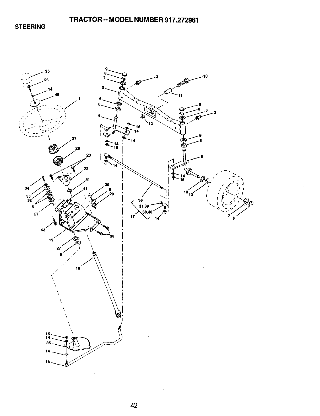
STEERING
TRACTOR - MODEL NUMBER 917.272961
13_3 iI
\
\
/ \
I iii
f
?
0
42
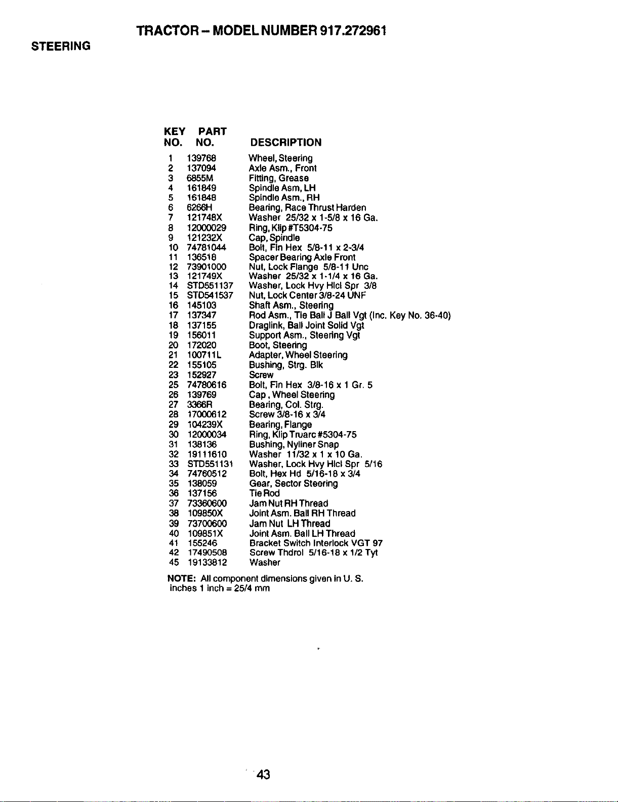
STEERING
TRACTOR - MODEL NUMBER 917.272961
KEY PART
NO. NO.
1 139768
2 137094
3 6855M
4 161849
5 161848
6 6266H
7 121748X
8 12000029
9 121232X
10 74781044
11 136518
12 73901000
13 121749X
14 STD551137
15 STD541537
16 145103
17 137347
18 137155
19 156011
20 172020
21 100711L
22 155105
23 152927
25 74780616
26 139769
27 3366R
28 1700(_12
29 104239X
30 12000034
31 138136
32 19111610
33 STD551131
34 74760512
35 138059
36 137156
37 73360600
38 109850X
39 73700600
40 109851X
41 155246
42 17490508
45 19133812
DESCRIPTION
Wheel,Steering
Axle Asm.,Front
Fitting,Grease
SpindleAsm,LH
SpindleAsm.,RH
Bearing,RaceThrustHarden
Washer 25/32 x 1-5/8x 16 Ga.
Ring,Klip#T5304-75
Cap,Spindle
Bolt,FinHex 5/8-11 x 2-3/4
SpacerBearingAxle Front
Nut,LockFlange 5/8-11 Uric
Washer 25/32 x 1-1/4 x 16 Ga.
Washer, LockHvyHlclSpr 3/8
Nut,LockCenter3/8-24 UNF
ShaftAsm.,Steering
RodAsm.,Tie BallJ BallVgt (Inc.KeyNo.36-40)
Draglink,BallJointSolidVgt
SupportAsm.,SteeringVgt
Boot,Steedng
Adapter,WheelSteering
Bushing,Strg.BIk
Screw
Bolt,FinHex 3/8-16 x 1 Gr. 5
Cap, Wheel Steering
Beadng,Col. Strg.
Screw3/8-16 x 3/4
Bearing,Flange
Ring,KlipTruarc#5304-75
Bushing,NylinerSnap
Washer 11/32xlx!0Ga.
Washer,LockHvy HlclSpr 5/16
Bolt,Hex Hd 5/16-18 x 3/4
Gear, SectorSteering
TieRod
JamNutRHThread
JointAsm.BallRH Thread
Jam Nut LHThread
JointAsm.BallLHThread
BracketSwitchInterlockVGT 97
ScrewThdrol 5/16-18 x 1/2Tyt
Washer
NOTE: All component dimensions given in U. S.
inches 1 inch = 25/4 mm
43
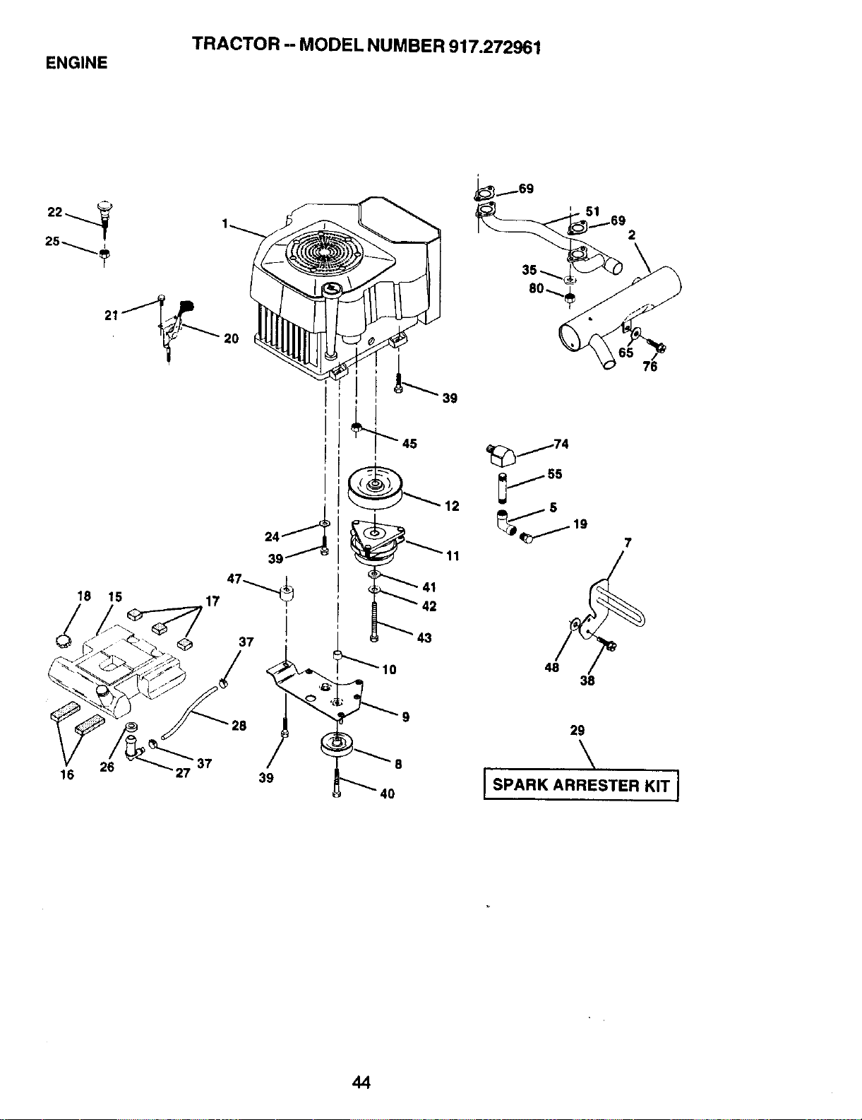
TRACTOR - MODEL NUMBER 917.272961
ENGINE
25
18 15
20
41
10
_j74
_j 55
js
48
38
2
7
76
16
26
_8
•37
39
9
8
|0
29
\
I SPARK ARRESTER KIT I
44
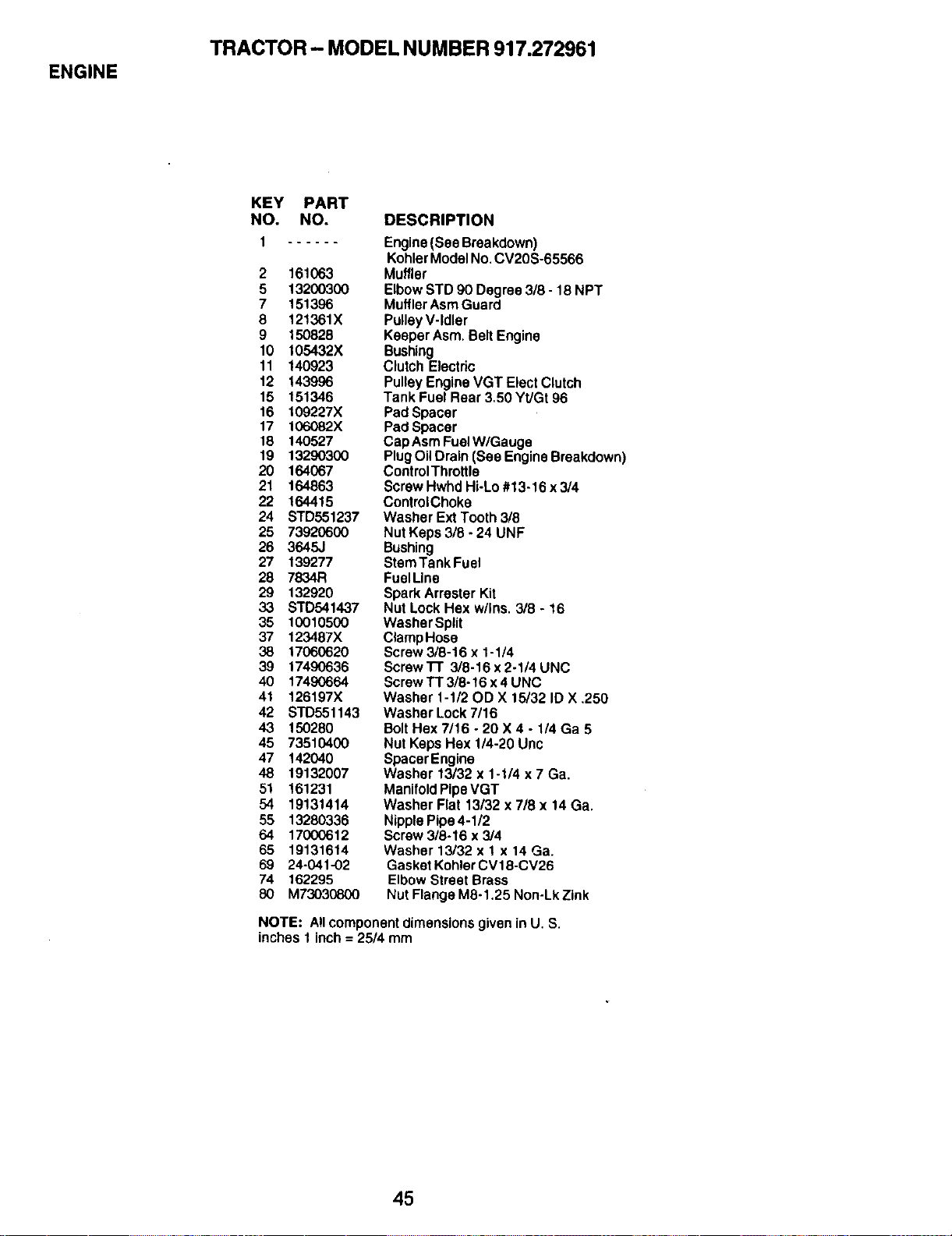
ENGINE
TRACTOR- MODEL NUMBER 917.272961
KEY PART
NO. NO.
1
2 161063
5 13200300
7 151396
8 121361X
9 150828
10 105432X
11 140923
12 143996
15 151346
16 109227X
17 106082X
18 140527
19 13290300
20 164067
21 164863
22 164415
24 STD551237
25 73920600
26 3645J
27 139277
28 7834R
29 132920
33 STD541437
35 10010500
37 123487X
38 17060620
39 17490636
40 17480664
41 126197X
42 STD551143
43 150280
45 73510400
47 142040
48 19132007
51 161231
54 19131414
55 13280336
64 17000612
65 19131614
69 24-041-02
74 162295
80 M73030800
DESCRIPTION
Engine (See Breakdown)
Kohler Model No. CV20S-65566
Muffler
Elbow STD 90 Degree 3/8 - 18 NPT
Muffler Asm Guard
Pulley V-Idler
Keeper Asm. Belt Engine
Bushing
Clutch Electric
Pulley Engine VGT Elect Clutch
Tank Fuel Rear 3,50 Yt/Gt 96
Pad Spacer
Pad Spacer
CapAsm Fuel W/Gauge
Plug Oil Drain (See Engine Breakdown)
Control Throttle
Screw Hwhd Hi-Lo #13-16 x 3/4
Control Choke
Washer Ext Tooth 3/8
Nut Keps 3/8 - 24 UNF
Bushing
Stem Tank Fuel
FuelLine
Spark Arrester Kit
Nut Lock Hex w/Ins. 3/8 - 16
Washer Split
ClampHose
Screw 3/8-16 x 1-1/4
Screw n 3/8-16 x 2-1/4 UNC
Screw "IT 3/8-16 x 4 UNC
Washer 1-1/20D X 15/32 ID X ,250
Washer Lock 7/16
Bolt Hex 7/16 - 20 X 4 - 1/4 Ga 5
Nut Keps Hex 1/4-20 Unc
Spacer Engine
Washer 13/32 x 1-1/4 x 7 Ca.
Manifold Pipe VGT
Washer Flat 13/32 x 7/8 x 14 Ca.
Nipple Pipe 4-1/2
Screw 3/8-16 x 3/4
Washer 13/32 x 1 x 14 Ca.
Gasket Kohler CV18-CV26
Elbow Street Brass
Nut Flange M8-1.25 Non-Lk Zink
NOTE: Allcomponentdimensionsgiven in U. S.
inches 1 inch= 25/4 mm
45
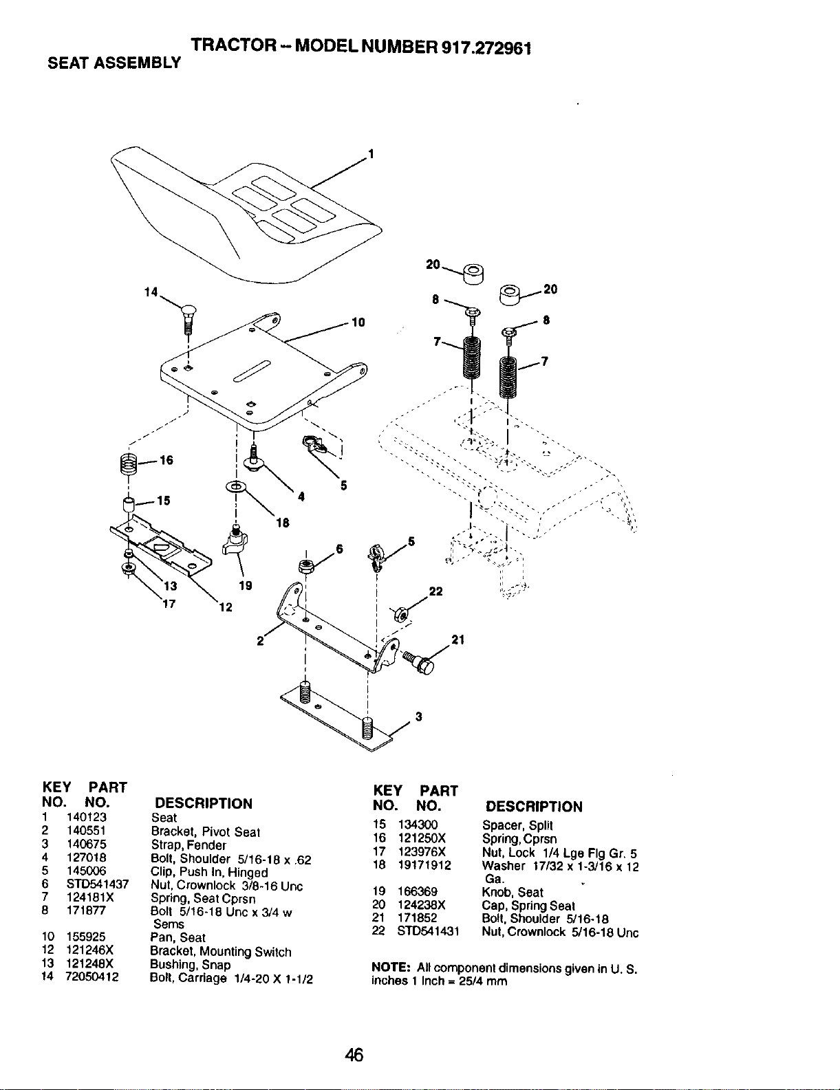
TRACTOR - MODEL NUMBER 917.272961
SEAT ASSEMBLY
21
KEY PART
NO. NO.
1 140123
2 140551
3 140675
4 127018
5 145006
6 STD541437
7 124181X
8 171877
10 155925
12 121246X
13 121248X
14 72050412
DESCRIPTION
Seat
Bracket, Pivot Seat
Strap, Fender
Bolt, Shoulder 5/16-18 x .62
Clip, Push In, Hinged
Nut, Crownlock 3/8-16 Unc
Spring, Seat Cprsn
Bolt 5/16-18 Unc x 3/4 w
Sems
Pan, Seat
Bracket, Mounting Switch
Bushing, Snap
Boll, Carriage 1/4-20 X 1-1/2
KEY PART
NO. NO.
15 134300
16 121250X
17 123976X
18 19171912
19 166369
20 124238X
21 171852
22 STD541431
DESCRIPTION
Spacer,Split
Spring,Cprsn
Nut,Lock 1/4 Lge FigGr. 5
Washer 17/32x 1-3/16 x 12
Ga.
Knob,Seat
Cap,SpringSeat
Bolt, Shou|der5/16.18
Nut,Crownlock5/16-18Unc
NOTE: All component dimensions g_ven in U. S.
inches 1 Inch = 25/4 mm
46
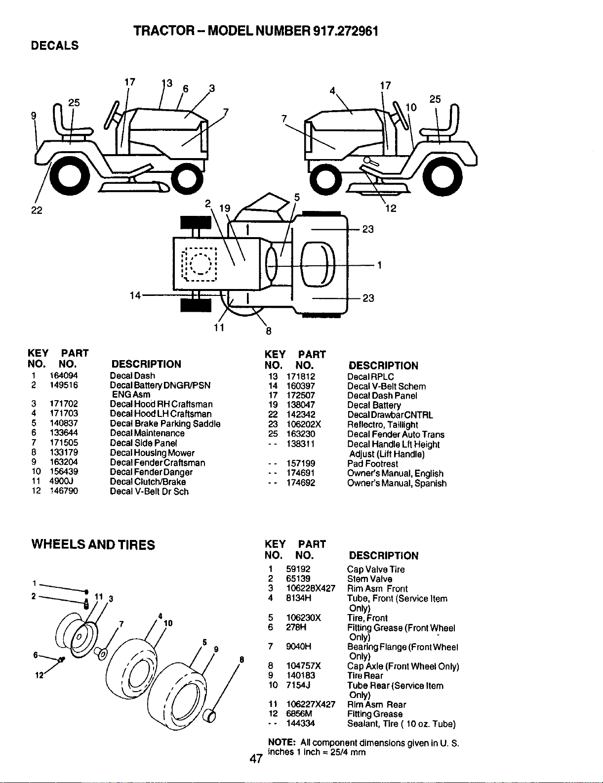
DECALS
TRACTOR - MODEL NUMBER 917.272961
9
25
17
3
6
7
4
17
25
22
14
2\m= \ 19
5
12
KEY PART
NO. NO,
1 164094
2 149516
3 171702
4 171703
5 140837
6 133644
7 171505
8 133179
9 163204
10 156439
11 4900J
12 146790
11
DESCRIPTION
DecalDash
DecalBatteP/DNGR/PSN
ENGAsm
DecalHoodRHCraftsman
DecalHoodLHCraftsman
DecalBrakeParkingSaddle
DecalMaintenance
DecalSidePanel
DecalHousingMower
DecalFenderCraftsman
DecaIFendarDanger
DecalClutch/Brake
DecalV-Belt DrSch
8
KEY PART
NO. NO. DESCRIPTION
13 171812 DecalRPLC
14 160397 DecalV-BeltSchem
17 172507 DecalDashPanel
19 138047 DecalBattery
22 142342 DecalDrawbarCNTRL
23 106202X Reflectro,Taillight
25 163230 DecalFenderAutoTrans
- - 138311 DecalHandleLftHeight
Adjust(LiftHandle)
-- 157199 PadFootrest
- - 174691 Owner'sManual,English
- - 174692 Owner'sManual,Spanish
WHEELS AND TIRES
3
7
4
10
KEY PART
NO. NO. DESCRIPTION
1 59192 Cap ValveTire
2 65139 StemValve
3 106226X427 RimAsm Front
4 8134H Tube, Front(ServiceItem
Only)
5 106230X Tire,Front
6 278H FittingGrease(FrontWheel
Only)
7 9040H BearingFlange(FrontWheel
Only)
8 104757X CapAxle(FrontWheelOnly)
9 140183 TireRear
10 7154J TubeRear (Servicettem
Only)
11 106227X427 RimAsm Rear
12 6856M FittingGrease
- - 144334 Sealant,Tire ( 10 oz.Tube)
NOTE: All component dimensions given in U, S.
inches 1 inch = 25/4 mm
47
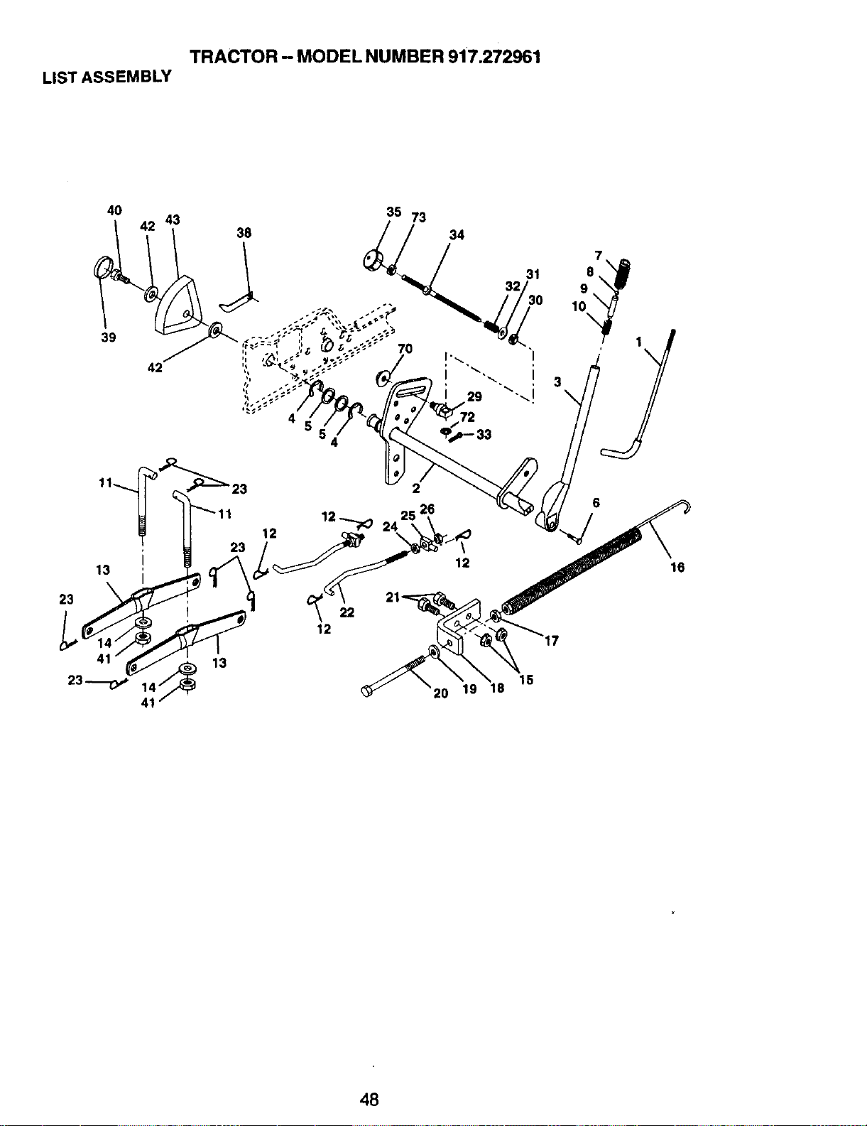
TRACTOR - MODEL NUMBER 917.272961
LISTASSEMBLY
40 43 35 73
38 34
32
I0
39
_-'_11123 12
12
23
22
12
2
15
20 19 18
16
48
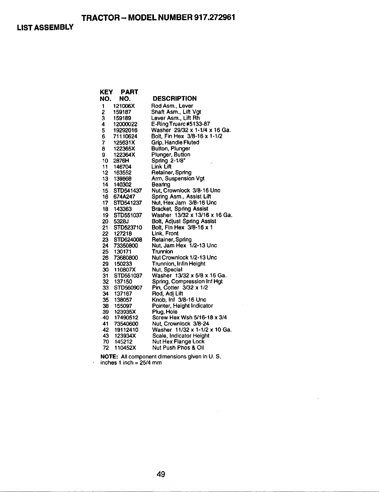
TRACTOR - MODEL NUMBER 917.272961
LIST ASSEMBLY
KEY PART
NO. NO. DESCRIPTION
1 121006X Rod Asm., Lever
2 159187 Shaft Asm., Lift Vgt
3 159189 Lever Asm., Lift Rh
4 12000022 E-Ring Truarc #5133-87
5 19292016 Washer 29/32 x 1-1/4 x 16 Ga.
6 71110624 Bolt, Fin Hex 3/8-16 x !-1/2
7 125631X Grip, Handle Fluted
8 122365X Button, Plunger
9 122364X Plunger, Button
10 2876H Spring 2-1/8"
11 146704 Link Lift
12 163552 Retainer, Spring
13 139868 Arm, Suspension Vgt
14 140302 Bearing
15 STD541437 Nut, Crownlock 3/8-16 Unc
16 674A247 Spring Asm., Assist Lift
17 STD541237 Nut, HexJam 3/8-16Unc
18 143363 Bracket, Spring Assist
19 STD551037 Washer 13/32x13/16x16Ga.
20 5328J Bolt, Adjust Spdng Assist
21 STD523710 Bolt, Fin Hex 3/8-16 x 1
22 127218 Link, Front
23 STD624008 Retainer, Spring
24 73350800 Nut, Jam Hex 1/2-13 Unc
25 130171 Trunnion
26 73680800 Nut Crownlock 1/2-13 Unc
29 150233 Trunnion, lnfinHeight
30 110807X Nut, Special
31 s'rD551037 Washer 13/32 x 5/8 x 16 Ga.
32 137150 Spring, Compression Inf Hgt
33 STD560907 Pin, Cotter 3/32 x 1/2
34 137167 Rod, Adj Lift
35 138057 Knob, Inf 3/8-16 Unc
38 155097 Pointer, Height Indicator
39 t23935X Plug, Hole
40 t7490512 Screw Hex Wsh 5/16-18 x 3/4
41 73540600 Nut, Crownlock 3/8-24
42 19112410 Washer 11/32x1-1/2xlOGa.
43 123934X Scale, Indicator Height
70 145212 Nut Hex Flange Lock
72 110452X Nut Push Phos & Oil
NOTE: All component dimensions given in U. S.
inches 1 inch = 25/4 mm
49
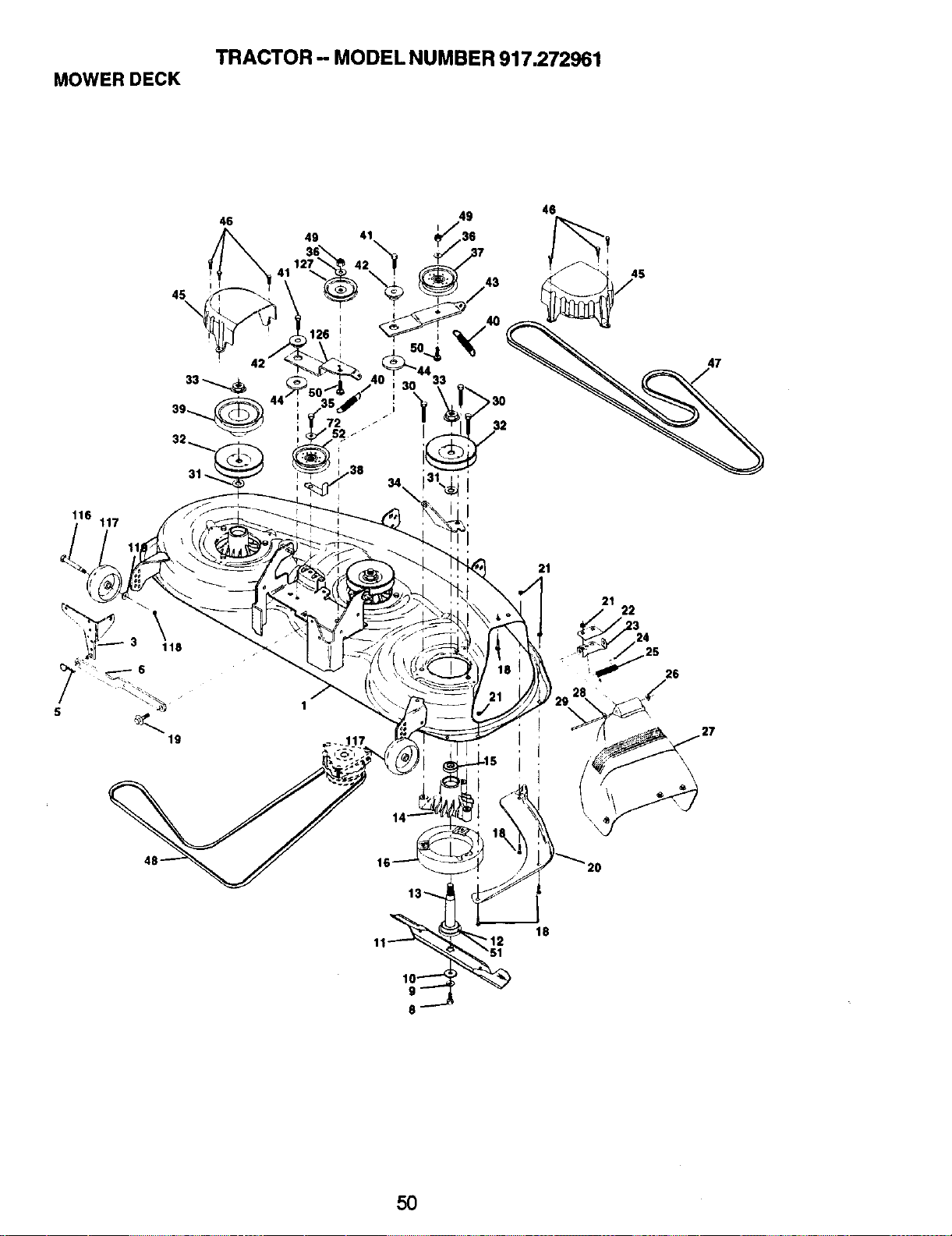
TRACTOR - MODEL NUMBER 917.272961
MOWERDECK
21
21
22
26
\
\
16
50
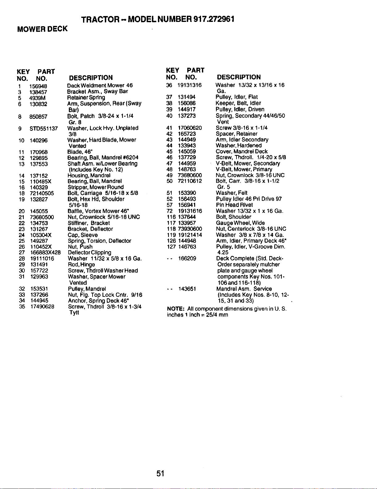
MOWER DECK
TRACTOR - MODEL NUMBER 917.272961
KEY PART
NO. NO.
1 156948
3 138457
5 4939M
6 130832
8 850857
9 STD551137
10 140296
11 170968
12 129895
13 137553
14 137152
15 110485X
16 140329
18 72140505
19 132827
20 145055
21 73680500
22 134753
23 131267
24 105304X
25 149287
26 110452X
27 166883X428
28 19111016
29 131491
30 157722
31 129963
32 153531
33 137266
34 144945
35 17490628
KEY PART
DESCRIPTION NO. NO.
DeckWeldment Mower 46 36 19131316
Bracket Asm., Sway Bar
Retainer Spdng 37 131494
Arm, Suspension, Rear(Sway 38 156086
Bar) 39 144917
Bolt, Patch 3/8-24 x 1-1/4 40 137273
Gr, 8
Washer, Lock Hvy. Unplated 41 17060620
3/8 42 165723
Washer, Hard Blade, Mower 43 144949
Vented 44 133943
Blade, 46" 45 145059
Bearing, Ball, Mandrel #6204 46 137729
ShaftAsm. w/LowerBeadng 47 144959
(Includes Key No. 12) 48 148763
Housing, Mandrel 49 73680600
Beadng, Ball, Mandral 50 72110612
Stripper, Mower Round
Bolt, Carriage 5/16-18 x 5/8 51 153390
Bolt, Hex Hd, Shoulder 52 156493
5/16-18 57 156941
Baffle, Vortex Mower46" 72 19131616
Nut, Crownlock 5/16-18 UNC 116 137644
Stifflner, Bracket 117 133957
Bracket, Deflector 118 73930600
Cap, Sleeve 119 19121414
Spring, Torsion, Deflector 126 144948
Nut, Push 127 146763
Deflector Clipping
Washer 11/32 x 5/8 x 16 Ga. - - 166209
Rod, Hinge
Screw, Thdroll Washer Head
Washer, Spacer Mower
Vented
Pulley, Mandrel - - 143651
Nut, Fig. Top Lock Cntr. 9/!6
Anchor, Spring Deck 46"
Screw, Thdroll 3/8-16 x 1-3/4
Tytt
DESCRIPTION
Washer 13/32 x 13/16 x 16
Ga.
Pulley, Idler, Fiat
Keeper, Belt, Idler
Pulley, Idler, Driven
Spring, Secondary 44/46/50
Vent
Screw 3/8-16 x 1-1/4
Spacer, Retainer
Arm, Idler Secondary
Washer, Hardened
Cover, Mandrel Deck
Screw, Thdroll. 1/4-20 x 5/8
V-Belt, Mower, Secondary
V-Belt, Mower, Primary
Nut, Crownlock 3/8-16 UNC
Bolt, Carr. 3/8-16 x 1-1/2
Gr. 5
Washer, Felt
Pulley Idler 46 Pri Drive 97
Pin Head Rivet
Washer 13/32 x 1 x 16 Ga.
Bolt, Shoulder
Gauge Wheel, Wide
Nut, Centerlock 3/8-16 UNC
Washer 3/8 x 7/8 x 14 Ga.
Arm, Idler, Primary Deck 46"
Pulley, Idler, V-Groove Dim.
4.25
Deck Complete (Std. Deck-
Order separately mulcher
plate and gauge wheel
components Key Nos. 101-
106 and 116-118)
Mandrel Asm. Service
(IncludesKey Nos.8-10, 12-
15,31 and 33)
NOTE: Allcomponentdimensions given in U. S.
inches 1 inch = 25/4 mm
51
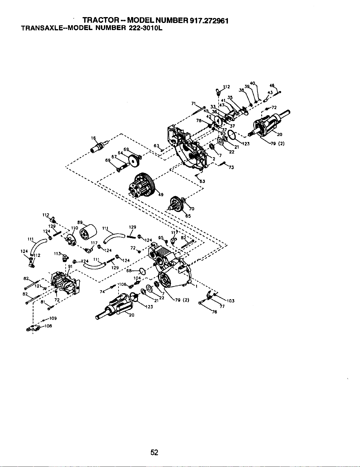
TRACTOR - MODEL NUMBER 917.272961
TRANSAXLE--MODEL NUMBER 222-3010L
52
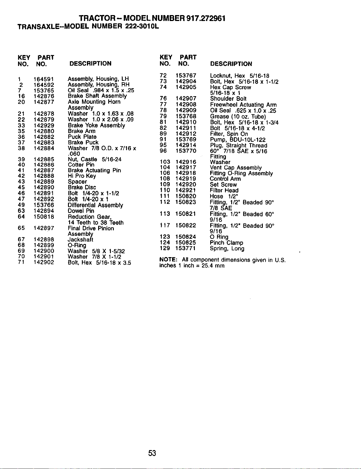
TRACTOR - MODEL NUMBER 917.272961
TRANSAXLE-MODEL NUMBER 222-3010L
KEY PART KEY PART
NO. NO. DESCRIPTION NO. NO.
72 153767
1 164591 Assembly, Housing, LH 73 142904
2 164592 Assembly, Housing, RH 74 142905
7 153765 Oil Seal .984 x 1.5 x .25
16 142876 Brake Shaft Assembly 76 142907
20 142877 Axle Mounting Horn 77 142908
Assembly 78 142909
21 142878 Washer 1.0 x 1.63 x .08 79 153768
22 142879 Washer 1.0 x 2.06 x .09 81 142910
33 142929 Brake Yoke Assembly 82 142911
35 142880 Brake Arm 89 142912
36 142882 Puck Plate 91 153769
37 142883 Brake Puck 95 142914
38 142884 Washer 7/80.D. x 7/16 x 96 153770
.060
39 142885 Nut, Castle 5/16-24 103 142916
40 142886 Cotter Pin 104 142917
41 142887 Brake Actuating Pin 106 142918
42 142888 Hi Pro Key 108 142919
43 142889 Spacer 109 142920
45 142890 Brake Disc 110 142921
46 142891 Bolt 1/4-20 x 1-1/2 111 150820
47 142892 Bolt 1/4-20xl 112 150823
49 153766 Differential Assembly
63 142894 Dowel Pin 113 150821
64 150818 Reduction Gear,
14 Teeth to 38 Teeth 117 150822
65 142897 Final Drive Pinion
Assembly 123 150824
67 142898 Jackshaft 124 150825
68 142899 O-Ring 129 153771
69 142900 Washer 5/8 X 1-5/32
70 142901 Washer 7/8 X 1-1/2
71 142902 Bolt, Hex 5/16-18 x 3.5
DESCRIPTION
Locknut, Hex 5/16-18
Bolt, Hex 5/16-18 x 1-1/2
Hex Cap Screw
5/16-18 x 1
Shoulder Bolt
Freewheel Actuating Arm
Oil Seal .625 x 1.0 x .25
Grease (10 oz. Tube)
Bolt, Hex 5/16-18 x 1-3/4
Bolt 5/16-18 x 4-1/2
Filter, Spin On
Pump, BDU-10L-122
Plug, Straight Thread
60° 7/18 SAE x 5/16
Fitting
Washer
Vent Cap Assembly
Fitting O-Ring Assembly
Control Arm
Set Screw
Filter Head
Hose 1/2"
Fitting, 1/2" Beaded 90°
7/8 SAE
Fitting, 1/2" Beaded 60°
9/16
Fitting, 1/2" Beaded 90°
9/16
O Ring
Pinch Clamp
Spring, Long
NOTE: All component dimensions given in U.S.
inches 1 inch = 25.4 mm
53
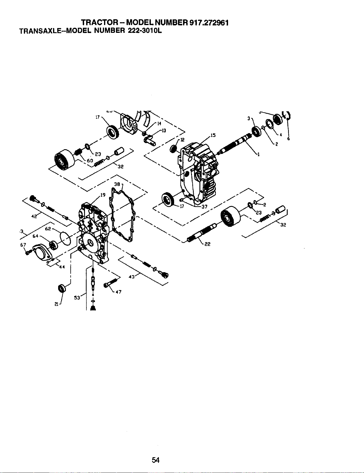
TRACTOR - MODEL NUMBER 917.272961
TRANSAXLE-MODEL NUMBER 222-3010L
<
54
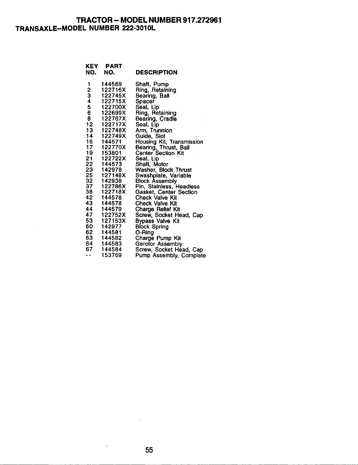
TRACTOR- MODEL NUMBER 917.272961
TRANSAXLE--MODEL NUMBER 222-3010L
KEY PART
NO. NO. DESCRIPTION
1 144569 Shaft, Pump
2 122716X Ring, Retaining
3 122745X Bearing, Ball
4 122715X Spacer
5 122700X Seal, Lip
6 122699X Ring, Retaining
8 122767X Bearing, Cradle
12 122717X Seal, Lip
13 122748X Arm, Trunnion
14 122749X Guide, Slot
15 144571 Housing Kit, Transmission
17 122770X Bearing, Thrust, Ball
19 153801 Center Section Kit
21 122722X Seal, Lip
22 144573 Shaft, Motor
23 142978 Washer, Block Thrust
25 127148X Swashplate, Variable
32 142938 Block Assembly
37 122786X Pin, Stainless, Headless
38 122718X Gasket, Center Section
42 144578 Check Valve Kit
43 144578 Check Valve Kit
44 144579 Charge Relief Kit
47 122752X Screw, Socket Head, Cap
53 127153X Bypass Valve Kit
60 142977 Block Spring
62 144581 O-Ring
63 144582 Charge Pump Kit
64 144583 Gerotor Assembly
67 144584 Screw, Socket Head, Cap
-- 153769 Pump Assembly, Complete
55
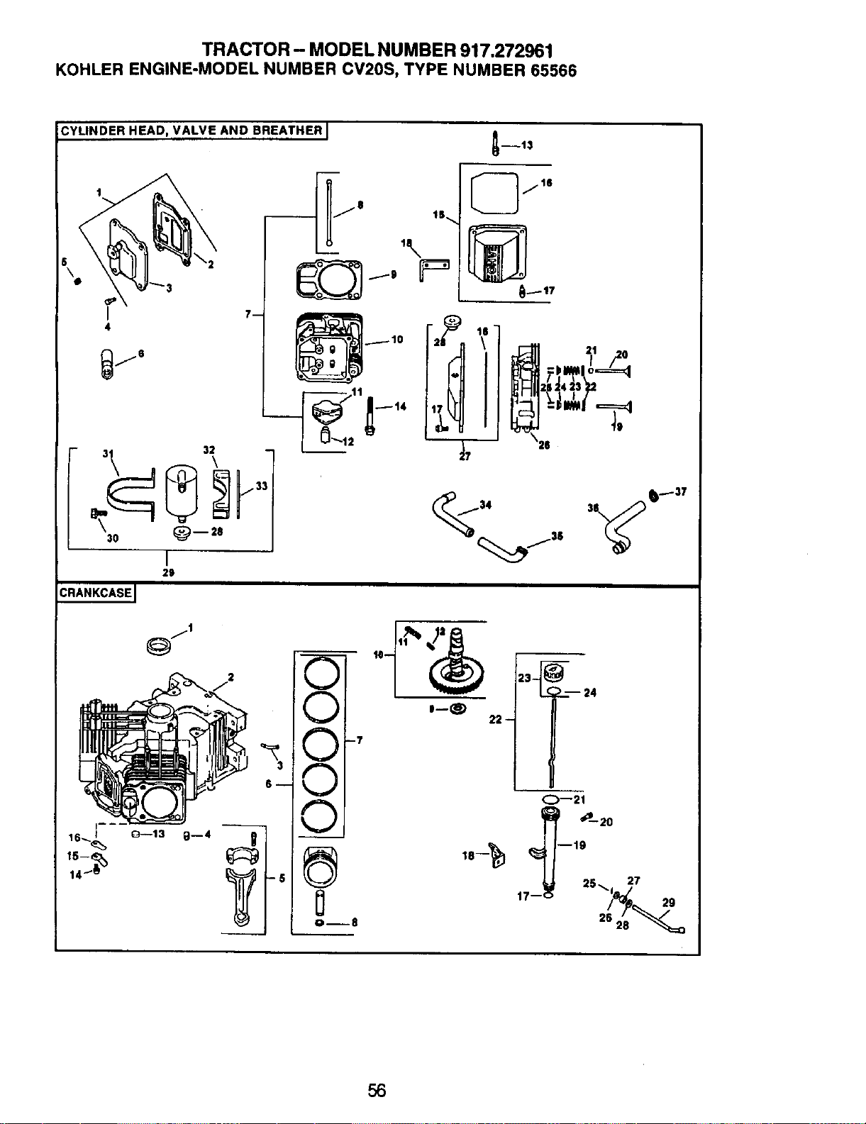
TRACTOR- MODEL NUMBER 917,272961
KOHLER ENGINE-MODEL NUMBER CV20S, TYPE NUMBER 65566
ICYLINDER HEAD, VALVE AND BREATHER I
I
4
_j6
7m
3\ 3_
j3
30 _) -- 28
CRANKCASEI
I
29
I_fl
U
V I
0
Ore8
21
23 _ 24
22-
O--21
_--20
I _I--7:_ 1_ 5 -_ d_ 7 29
56
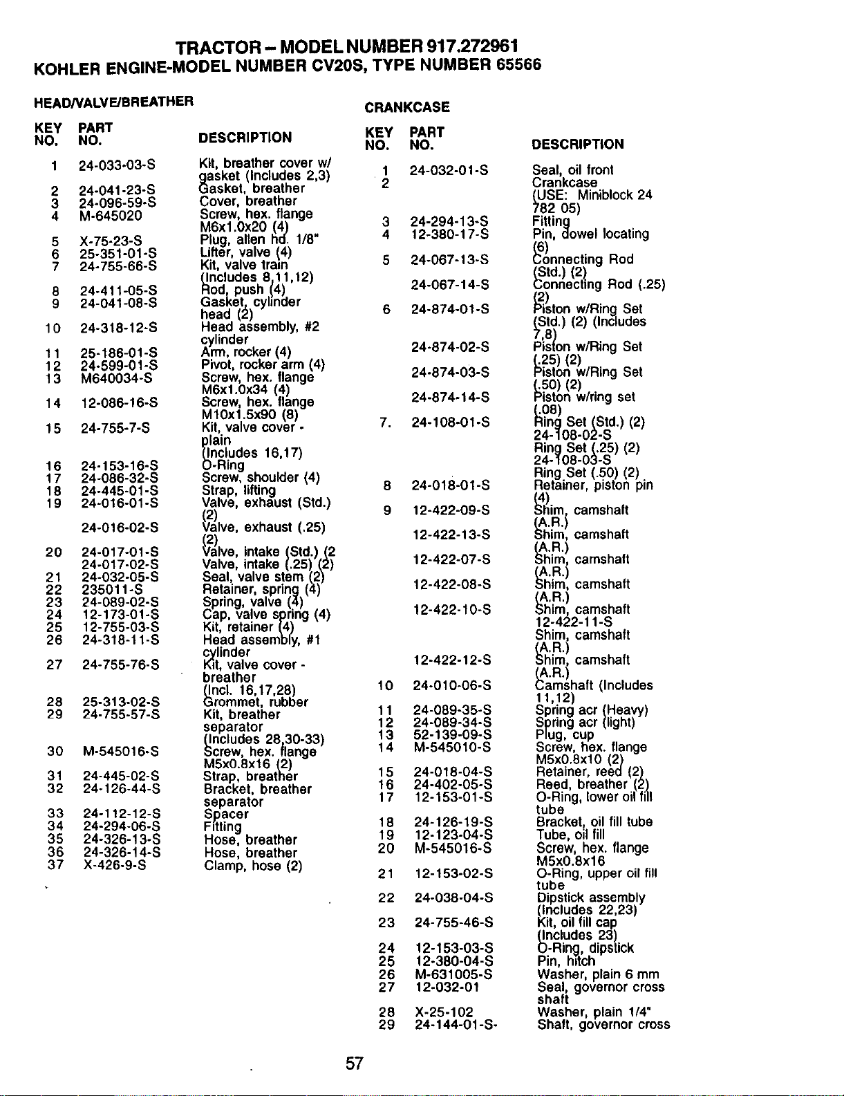
TRACTOR - MODEL NUMBER 917.272961
KOHLER ENGINE-MODEL NUMBER CV20S, TYPE NUMBER 65566
HEADNALVE/BREATHER
KEY PART
NO. NO. DESCRIPTION
24-033-03-S
2 24-041-23-S
3 24-096-59-S
4 M-645020
5
6
7
X-75-23-S
25-351-01-S
24-755-66-S
24-411-05-S
24-041-08-S
10 24-318-12-S
11 25-186-01-S
12 24-599-01-S
13 M640034-S
14 12-086-16-S
15 24-755-7-S
16 24-153-16-S
17 24-086-32-S
18 24-445-01-S
19 24-016-01-S
24-016-02-S
20 24-017-01-S
24-017-02-S
21 24-032-05-S
22 235011-S
23 24-089-02-S
24 12-173-01-S
25 12-755-03-S
26 24-318-11-S
27 24-755-76-S
28 25-313-O2-S
29 24-755-57-S
30 M-545016-S
31 24-445-02-S
32 24-126-44-S
33 24-112-12-S
34 24-294-06-S
35 24-326-13-S
36 24-326-14-S
37 X-426-9-S
CRANKCASE
KEY PART
NO. NO.
Kit, breather cover w/
1 24-032-01 -S
_asket (includes 2,3)
asket, breather 2
Cover, breather
Screw, hex. flange
M6xl.0x20 (4) 3 24-294-13-S
Plug alien hal. 1/8" 4 12-380-17-S
Lifter, vave (4)
Kit, valve train 5 24-067-13-S
_ncludes 8,11,12)
odr push (4) 24-067-14-S
GasKet, cyhnder
head (2) 6 24-874-01-S
Head assembly, #2
cylinder
Arm, rocker (4) 24-874-02-S
Pivot, rocker arm (4) 24-874-03-S
Screw, hex. flange
M6xl.0x34 (4)
Screw, hex. flange 24-874-14-S
M10xl.5x90 (8)
Kit valve cover- 7. 24-108-01-S
plain
(Includes 16,17)
O-Ring
_crew, shoulder (4) 8 24-018-01-S
Strap, lifting
Valve, exhaust (Std.) 9 12-422-09-S
Cv2)
alve, exhaust (.25) 12-422-13-S
V2a)lve,intake (Std.) (2
Valve, intake (.25) (2) 12-422-07-S
Seal, valve stem (2)
Retainer, spring (4) 12-422-08-S
Spring, valve (4)
Cap, valve spring (4) 12-422-10-S
Kit, retainer (4)
Head assembly, #1
_/ttlinder
, valve cover - 12-422-12-S
breather
_ncl. 16,17,28) 10 24-010-06-S
rommet, rubber
Kit, breather 11 24-089-35-S
12 24-089-34-S
separator
(Includes 28,30-33) 13 52-139-09-S
Screw, hex. flange 14 M-545010-S
MSxO.8x16 (2)
Strap, breather 15 24-018-04-S
Bracket, breather 16 24-402-05-S
17 12-153-01-S
separator
S_acer
Fitting 18 24-126-19-S
Hose, breather 19 12-123-04-S
Hose, breather 20 M-545016-S
Clamp, hose (2) 21 12-153-02-S
22 24-038-04-S
23 24-755-46-S
24 12-153-03-S
25 12-380-04-S
26 M-631005-S
27 12-032-01
28 X-25-102
29 24-144-01-S-
DESCRIPTION
Seal, oil front
Crankcase
tUSE: Miniblock24
2 05)
Fitting
Pin, dowel locating
_E)nnecting Rod
_Std.) (2}
onnechng Rod (.25)
_2)ton w/Ring Set
(Std.) (2) (Includes
7,8)
Piston wiRing Set
_25) (2)
iston w/Ring Set
_50) (2)
iston w/ring set
(..o8)
Ring Set (Std.) (2)
24-108-02-S
Ring Set (,25) (2)
24-108-03-S
Ring Set (.50) (2)
Retainer, piston pin
_Ah).i_.i camshaft
him, camshaft
_A.R,)
im, camshaft
_A,R,)
im, camshaft
_A.R,)
im, camshaft
12-422-11-S
Shim, camshaft
_A.R.)
im, camshaft
_A.R.)
amshaft (Includes
11,12)
Spring acr (Heavy)
Spring acr (light)
Plug, cup
Screw, hex. flange
M5x0.8xl0 (2)
Retainer, reed (2)
Reed breather (2)
O-Ring, lower oil fl
tube
Bracket, oil fill tube
Tube, oil fill
Screw, hex. flange
M5x0.8x16
O-Ring, upper oil fill
tube
Dipstick assembly
(Includes 22,23)
Kit, oil fillcap
(Includes 23)
O-Ring, dipstick
Pin, hitch
Washer, plain 6 mm
Seal, governor cross
shaft
Washer, plain 1/4"
Shaft, governor cross
57
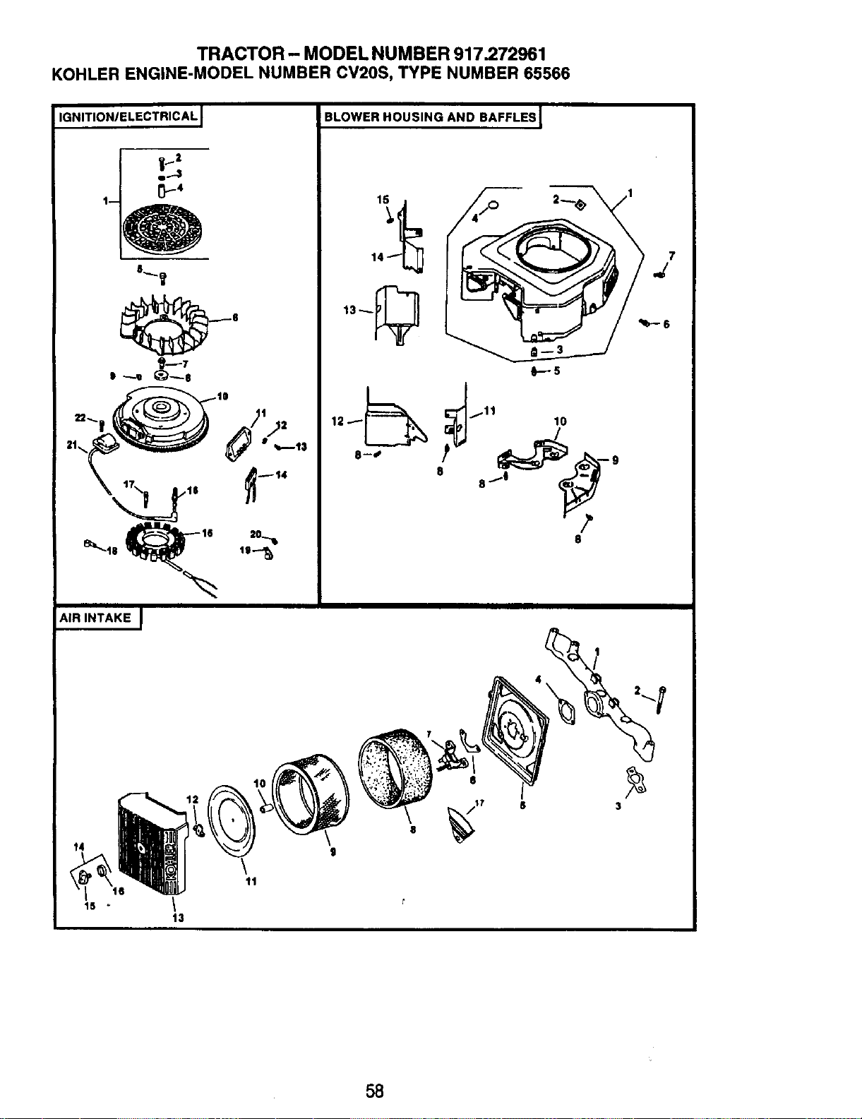
TRACTOR - MODEL NUMBER 917,272961
KOHLER ENGINE-MODEL NUMBER CV20S, TYPE NUMBER 65566
IGNITION/ELECTRICAL J
a.-.t
AIR INTAKE I
BLOWER HOUSING AND BAFFLES I
141_
13_
0---5
_-_ _.11 10
8
14
tl
8
$
3
58
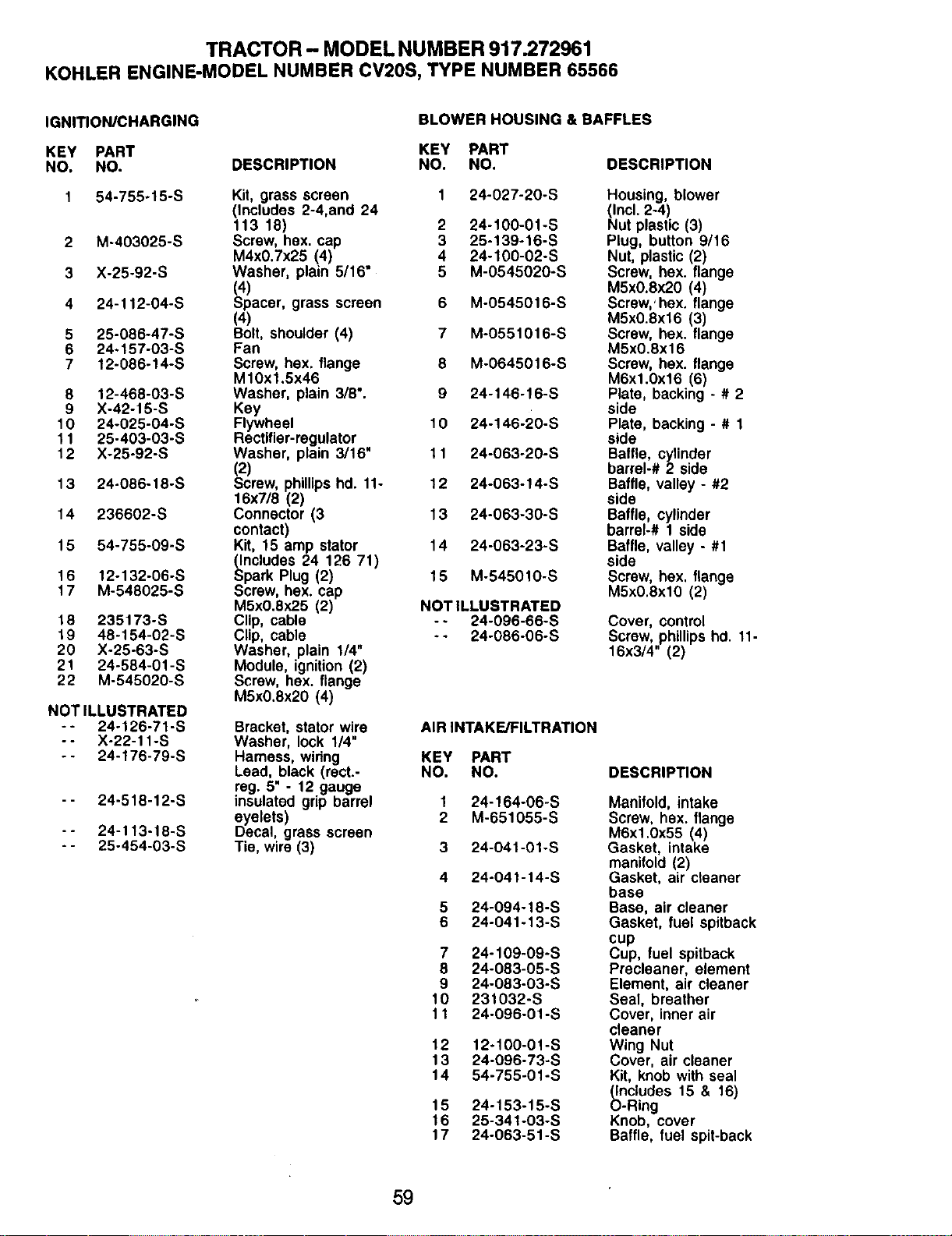
TRACTOR - MODEL NUMBER 917.272961
KOHLER ENGINE-MODEL NUMBER CV20S, TYPE NUMBER 65566
IGNITION/CHARGING
KEY PART
NO. NO.
1 54-755-15-S
2 M-403025-S
3 X-25-92-S
4 24-112-04-S
5 25-086-47-S
6 24-157-03-S
7 12-086-14-S
8 12-468-03-S
9 X-42-15-S
10 24-025-04-S
11 25-403-03-S
12 X-25-92-S
13 24-086-18-S
14 236602-S
15 54-755-09-S
16 12-132-06-S
17 M-548025-S
18 235173-S
19 48-154-02-S
20 X-25-63-S
21 24-584-01-S
22 M-545020-S
NOT ILLUSTRATED
- - 24-126-71-S
-- X-22-11-S
- - 24-176-79-S
- - 24-518-12-S
-- 24-t 13-18-S
- - 25-454-03-S
BLOWER HOUSING & BAFFLES
KEY PART
DESCRIPTION NO. NO.
Kit, grass screen 1 24-027-20-S
(includes 2-4,and 24
113 18) 2 24-100-01-S
Screw, hex. cap 3 25-139-16-S
M4x0.7x25 (4) 4 24-100-02-S
Washer, plain 5/16" 5 M-0545020-S
(4)
Spacer, grass screen 6 M-0545016-S
(4)
Bolt, shoulder (4) 7 M-0551016-S
Fan
Screw, hex. flange 8 M-0645016-S
M10x1.5x46
Washer, plain 3/8% 9 24-146-16-S
Key
Flywheel 10 24-146-20-S
Rectifier-regulator
Washer, plain 3/16" 11 24-063-20-S
(2)
Screw, phillipshd. 11- 12 24-063-14-S
16x7/8
(2)
Connector (3 13 24-063-30-S
contact)
Kit, 15 amp stator 14 24-063-23-S
_ncludes 24 126 71)
park Plug (2) 15 M-545010-S
Screw, hex. cap
M5x0.8x25 (2) NOT ILLUSTRATED
Clip, cable -- 24-096-66-S
Clip, cable -- 24-086-06-S
Washer, plain 1/4"
Module, ignition(2)
Screw, hex. flange
M5x0.ex20 (4)
Bracket, stator wire AIR INTAKE/FILTRATION
Washer, lock 1/4"
Harness, widng KEY PART
Lead, black (rect.- NO. NO.
reg. 5" - 12 gauge
insulated grip barrel 1 24-164-06-S
eyelets) 2 M-651055-S
Decal, grass screen
Tie, wire (3) 3 24-041-01-S
DESCRIPTION
Housing, blower
(Incl. 2-4)
Nut plastic (3)
Plug, button 9/16
Nut, plastic (2)
Screw, hex. flange
M5x0.ex20 (4)
Screw,' hex. flange
M5x0.8x16 (3)
Screw, hex. flange
M5x0.8x16
Screw, hex. flange
M6xl.0x16 (6)
Plate, backing - # 2
side
Plate, backing - # 1
side
Baffle, cylinder
barrel-# 2 side
Baffle, valley - #2
side
Baffle, cylinder
barrel-# 1 side
Baffle, valley - #1
side
Screw, hex. flange
M5x0.exl0 (2)
Cover, control
Screw, phillips hd. 11-
16x3/4" (2)
4 24-04t-t4-S
5 24-094-18-S
6 24-041-13-S
7 24-109-09-S
8 24-083-05-S
9 24-083-03-S
10 231032-S
11 24-096-01-S
12 12-100-01-S
13 24-096-73-S
14 54-755-01-S
15 24-153-15-S
16 25-341-03-S
17 24-063-51-S
DESCRIPTION
Manifold, intake
Screw, hex. flange
M6x1.0x55 (4)
Gasket, intake
manifold (2)
Gasket, air cleaner
base
Base, air cleaner
Gasket, fuel spitback
cup
Cup, fuel spitback
Precleaner, element
Element, air cleaner
Seal, breather
Cover, inner air
cleaner
Wing Nut
Cover. air cleaner
Kit, knob with seal
_)ncludes 15 & 16)
-Ring
Knob, cover
Baffle, fuel spit-back
59
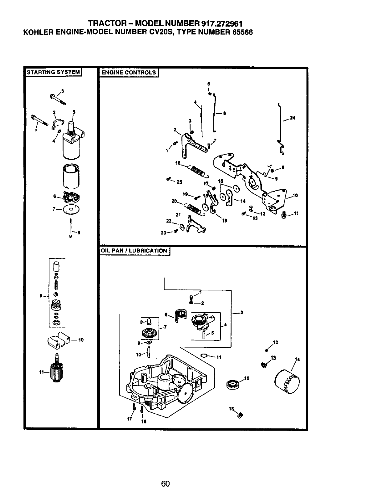
TRACTOR - MODEL NUMBER 917.272961
KOHLER ENGINE-MODEL NUMBER CV20S, TYPE NUMBER 65566
;TARTING SYSTEM J
2 S
"-8
ENGINE CONTROLS
4
\
3
6
tl
mS
124
1/_* (_i /
,o''-.-',_---1, "_':-:/I.
22,,,... _ t8 13
--10
"-Iil
OIL PAN / LUBRICATION I
2
6O
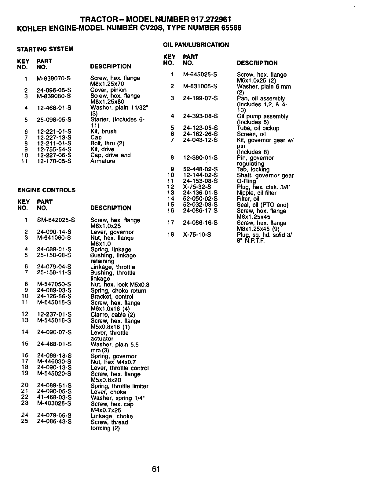
TRACTOR - MODEL NUMBER 917.272961
KOHLER ENGINE-MODEL NUMBER CV20S, TYPE NUMBER 65566
STARTING SYSTEM
KEY PART
NO. NO. DESCRIPTION
1 M-839070-S
2 24-096-05-S
3 M-839080-S
4 12-468-O1-S
5 25-098-05-S
6 12-221-01-S
7 12-227-13-S
8 12-211-01-S
9 12-755-54-S
10 12-227-06-S
11 12-170-05-S
ENGINE CONTROLS
KEY PART
NO. NO,
1 SM-642025-S
2 24-090-14- S
3 M-641060-S
4 24-089-01 -S
5 25-158-08-S
6 24-079-64-S
7 25-158-11-S
8 M-547050-S
9 24-089-03-S
10 24-126-56-S
11 M-645016-S
12 12-237-01-S
13 M-545016-S
14 24-090-07-S
15 24-468-01 -S
16 24-089-18-S
17 Mo446030-S
18 24-090-13-S
19 M-545020-S
20 24-089-51-S
21 24-090-05-S
22 41-468-03-S
23 M-403025-S
24 24-079-05-S
25 24-086-43-S
OIL pAN/I UBRICATION
KEY PART
NO. NO.
1 M-645025-S
Screw, hex. flange
M8x1.25x70 2 M-631005-S
Cover, inion
Screw, Rex. flange 3 24-199-07-S
M8x1.25x80
Washer, plain 11/32"
_3)rter, (Includes 6- 4 24-393-08-S
11) 5 24-123-05-S
Kit, brush 6 24-162-26-S
Cap 7 24-043-12-S
Bolt, thru (2}
Kit, drive
Cap, drive end 8 12-380-0"1-S
Armature
DESCRIPTION
Screw, hex, flange
M6x1.0x25
Lever, governor
Nut, hex. flange
M6x1.0
Spring, linkage
Bushing, linkage
retaining
Linkage, throttle
Bushing, throttle
linkage
Nut, nex. lock M5xO,8
Spring, choke return
Bracket, control
Screw, hex. flange
M6xl.0x16 (4)
Clamp, cable (2)
Screw, hex. flange
M5x0.Sx16 (1)
Lever, throttle
actuator
Washer, plain 5.5
mm (3)
Spring, governor
Nut, hex M4x0.7
Lever, throttle control
Screw, hex. flange
M5x0.Sx20
Spring, throttle limiter
Laver, choke
Washer, spring 1/4"
Screw, hex. cap
M4x0.7x25
Linkage, choke
Screw, thread
forming (2)
9 52-448-02-S
10 12-144-02-S
11 24-153-08-S
12 X-75-32-S
13 24-136-01-S
14 52-050.02-S
15 52-032-08-S
16 24-086-17-S
17 24-086-16-S
18 X-75-10-S
DESCRIPTION
Screw, hex. flange
M6x1.0x25 (2)
Washer, plain 6 mm
(2)
Pan, oil assembly
(Includes 1,2, & 4-
to)
Oil pump assembly
(Includes 5)
Tube, oil pickup
Screen, oil
Kit, governor gear w/
ncludes 8)
in, governor
regulating
Tab, locking
Shaft, governor gear
O-Ring
Plug, hex. ctsk. 3/8"
Nipple, oil filter
Filter, oil
Seal, oil (PTO end)
Screw, hax. flange
M8x1.25x45
Screw, hex. flange
M8xt.25x45 (9)
Plug, sq. hd, solid 3/
8" N.P.T.F.
61
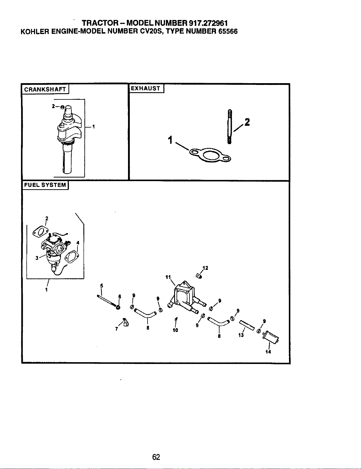
TRACTOR - MODEL NUMBER 917.272961
KOHLER ENGINE-MODEL NUMBER CV20S, TYPE NUMBER 65566
CRANKSHAFT J
FUEL SYSTEM J
--1
EXHAUSTJ
\
/
/
1
5
I o
¢ \
7 8
40 ' _ _d.,,,.
I'"
t4
62
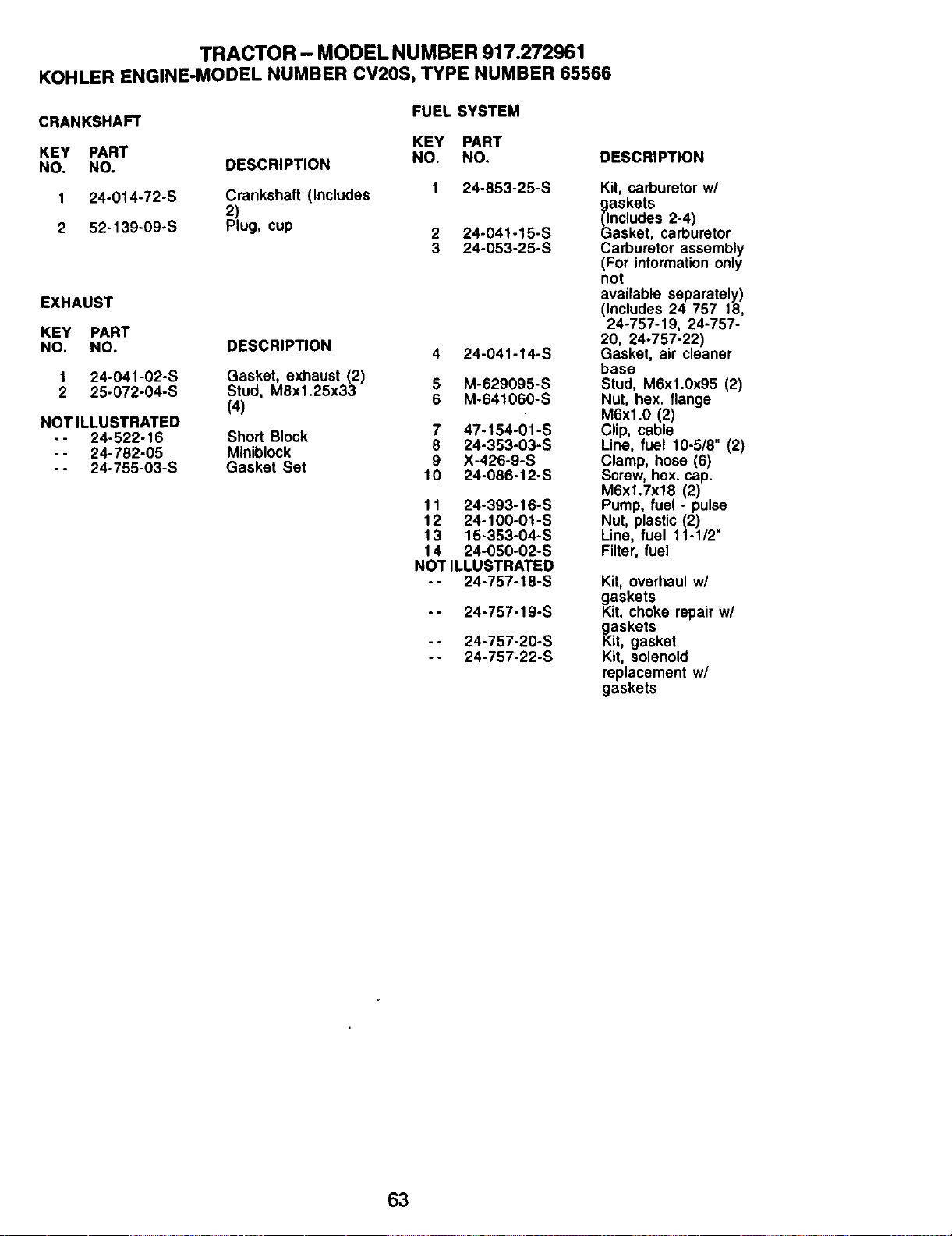
TRACTOR - MODEL NUMBER 917.272961
KOHLER ENGINE-MODEL NUMBER CV20S, TYPE NUMBER 65566
CRANKSHAFT FUEL SYSTEM
KEY PART
KEY PART NO. NO.
NO. NO, DESCRIPTION
1 24-014-72-S Crankshaft (Includes 1 24-853-25-S
2)
2 52-139-09-S Plug, cup 2 24-041-15-S
3 24-053-25-S
EXHAUST
KEY PART
NO. NO. DESCRIPTION 4 24-041-14-S
1 24-041-02-S Gasket, exhaust (2) 5 M-629095-S
2 25-072-04-S Stud, M8x1_25x33
(4) 6 M-641060-S
NOT ILLUSTRATED
-- 24-522-16 Short Block 7 47-154-01-S
- - 24-782-05 Miniblock 8 24-353-03-S
9 X-426-9-S
- - 24-755-03-S Gasket Set 10 24-086-12-S
11 24-393-16-S
12 24-100-01-S
13 15-353-04-S
14 24-050-02-S
NOT ILLUSTRATED
- - 24-757-18-S
- - 24-757-19-S
- - 24-757-20-S
- - 24-757-22-S
DESCRIPTION
Kit, carburetor w/
askets
ncludes 2-4)
asket, carburetor
Carburetor assembly
(For information only
not
available separately)
(Includes 24 757 18,
24-757-19, 24-757-
20, 24°757-22)
Gasket, air cleaner
base
Stud, M6x1.0x95 (2)
Nut, hex. flange
M6xl.0 (2)
Clip, cable
Line, fuel 10-5/8" (2)
Clamp, hose (6)
Screw, hex. cap.
M6xl.7x18 (2)
Pump, fuel - pulse
Nut, plastic (2)
Line, fuel 11-1/2"
Filter, fuel
Kit, overhaul w/
gKaskets
it, choke repair wl
i_askets
it, gasket
Kit, solenoid
replacement w/
gaskets
63

64

65


SUGGESTED GUIDE FOR SIGHTING SLOPES FOR SAFE OPERATION
ONLY RIDE UP AND DOWN HILL,
NOT ACROSS HILL
SIGHT AND HOLD THIS LEVEL WITH
I_IL Operate your Tractor up and down the face of slopes (not I
I
greater than 15°), never across the face. Make turns gradu- I
ally to prevent tipping or loss of control. Exercise extreme I
caution when changing direction on slopes. I

!iiiiiiiiiiiiii_
For repair of major brand appliances in your own home...
no matter who made it, no matter who sold it!
1-800-4-MY-HOME s. Anytime, dayornight
(1-800-4694663)
www.sears.com
To bring in products such as vacuums,
lawn equipment and electronics for repair, call for
the location of your nearest Sears Parts & Repair Center.
1-800-488-1222 Anytime, day or night
www.sears.com
iiiiii'!_iiiiii!_
iiii:_iiiii_i!i
iiii!ii!i!::_ii
!iii!iiiii!il
iii'iiii*i:iii For the replacement parts, accessories and owner's manuals
iii!i!iiiii!iii that you need to do-it-yourself, call Sears PartsDirectSM!
iiiiiiiii_:ililil
i;ili;i;:; iii 1-800-366-PART 6arn-,t p.m.CST,
:iii:i:!i:i!:
_:_'_' (1 800 366 7278) days a week
i:i:i¢_:i:ii
:i!:ii:!:i:i
7 a.m. - 5 p.m. CST, Mon.- Sat.
Para pedir serviciode reparaci6n a domicilio, Au Canada pourservice en fran_tais:
y para ordenar piezas con entrega a domicilio: 1-877-LE-FOYER s. i:
1 "888"SU'HOGARSM(1-888-'84-6427} ("8'7"533"693')
© Sears, Roebuck and Co.
® Registered Trademark / T. Trademark of Sears, Roebuck and Co.
® Marca Registrada / _" Marca de F&brica de Sears, Roebuck and Co.
174691 3.31.00 JH Printed in U.S.A.


