1
Owner’s Manual
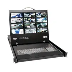
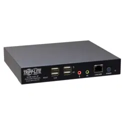
HDMI KVM over IP Remote
User Console Station
Model: B064-000-STN
1111 W. 35th Street, Chicago, IL 60609 USA • tripplite.com/support
Copyright © 2020 Tripp Lite. All rights reserved.
WARRANTY REGISTRATION
Register your product today and be
automatically entered to win an ISOBAR
®
surge protector in our monthly drawing!
tripplite.com/warranty

2
1. Overview 4
1.1 Features 4
1.2 Package Contents 4
1.3 Optional Accessories 4
1.4 System Requirements 4
1.5 Introduction 5
2. Setup 6
2.1 Mounting Instructions 6
2.2 Installation 8
3. Operation 9
3.1 Logging In 9
3.2 Dashboard 10
3.3 Dashboard Operation 11
3.4 Tab/Panel Array Display 13
and Management
3.4.1 Tab Options 13
3.4.2 Panel Array Options 14
3.4.3 Tab/Panel Array 16
Management
3.4.4 Adding a Tab 17
3.4.5 Adding Another Tab 18
3.4.6 Editing a Tab 18
3.4.7 Deleting a Tab 18
4. Device Management 19
4.1 Device List 19
4.1.1 Search 20
4.1.2 Removing a Device 20
4.1.3 Adding a Device 20
4.1.4 Changing Connection 21
Information
5. System Configuration 22
5.1 User Management 22
5.1.1 Users and Groups 22
5.1.1.1 Add User 23
5.1.1.2 Copy User 25
5.1.1.3 Modify User 25
5.1.1.4 Delete User 25
5.1.2 Managing (Assigning) 26
Users and Groups
5.1.2.1 Using User 26
Configuration Page
5.1.2.2 Using Group 27
Configuration Page
5.1.3 Device Assignment 28
5.1.3.1 Using Device 28
Configuration Page
5.2 Device Management 30
5.2.1 Device Information 30
5.2.2 Network 31
5.2.2.1 IP Installer 32
5.2.2.2 IPv4 Settings 32
5.2.2.3 IPv6 Settings 32
5.2.2.4 Finishing Up 32
5.2.3 Advanced Network 33
Management Settings
(ANMS)
5.2.3.1 RADIUS Settings 34
5.2.3.2 AD/LDAP Settings 34
5.2.3.3 Finishing Up 35
5.2.4 Security 35
5.2.4.1 Login Failures 36
5.2.4.2 Account Policy 36
5.2.4.3 Working Mode 36
5.2.4.4 Finishing Up 36
Table of Contents

3
Table of Contents
5.3 Maintenance 37
5.3.1 Upgrade Main Firmware 37
5.3.2 Firmware Upgrade 38
Recovery
5.3.3 Backup/Restore 38
5.3.3.1 Backup 39
5.3.3.2 Restore 40
5.3.4 Push/Pull Configuration 41
5.3.4.1 Pull Configuration 42
5.3.4.2 Push Configuration 42
5.3.5 Terminal 43
5.3.6 System Operation 44
5.3.6.1 Reset Default 44
Values
5.3.6.2 Reset on Exit 44
5.4 Quick User Configuration 45
6. Toolbar Interface 46
6.1 Exit Remote Location 47
6.2 Video Settings 48
6.3 Macros 49
6.3.1 Hotkeys 50
6.3.2 User Macros 51
6.3.3 Import/Export Macros 55
6.3.4 Delete Macros 55
6.3.5 Search Macros 56
6.3.6 System Macros 56
6.4 Further Configuration 57
6.4.1 Virtual Media 58
6.4.2 Message Board 60
6.4.2.1 Buttons 60
6.4.2.2 Message Display 61
Panel
6.4.2.3 Compose Panel 61
6.4.2.4 User List Panel 61
6.4.3 Mouse Sync Mode 62
6.4.3.1 Automatic Mouse 62
Synchronization
6.4.3.2 Manual Mouse 62
Synchronization
6.4.3.3 Mac and Linux 62
Considerations
7. Specifications 63
8. Warranty and 64
Product Registration

4
1. Overview
1.1 Features
• Standalone HDMI user console station provides remote access to your B064-IPG KVM over IP switches from one centralized
location.
• Enterprise-level Java-free console station replaces a PC, laptop or notebook computer.
• With no operating system, the console station eliminates the need for system or software updates and provides security
against virus threats and data protection.
• Monitors the video output of up to 64 servers on the primary display using panel array mode.
• Supports boundless switching when cascaded with another B064-000-STN
• Virtual media lets you remotely connect storage media to a target server anywhere on the network.
• HDMI port supports HD resolutions up to 1920 x 1200 @ 60 Hz.
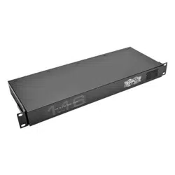
• Included mounting plate enables wall mounting or space-saving 0U rack mounting.
1.2 Package Contents
• B064-000-STN Console Station
• Rubber Feet (x4)
• Mounting Plate
• External Power Supply (100V-240V) with C13 to NEMA 5-15P Power Cord
1.3 Optional Accessories
• P569-Series High Speed HDMI Cables
1.4 System Requirements
• Tripp Lite’s B064-IPG-Series KVM over IP with Firmware Version of V1.1.102 or Above
• USB Mouse/Keyboard & HDMI Monitor
5
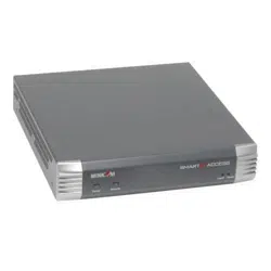
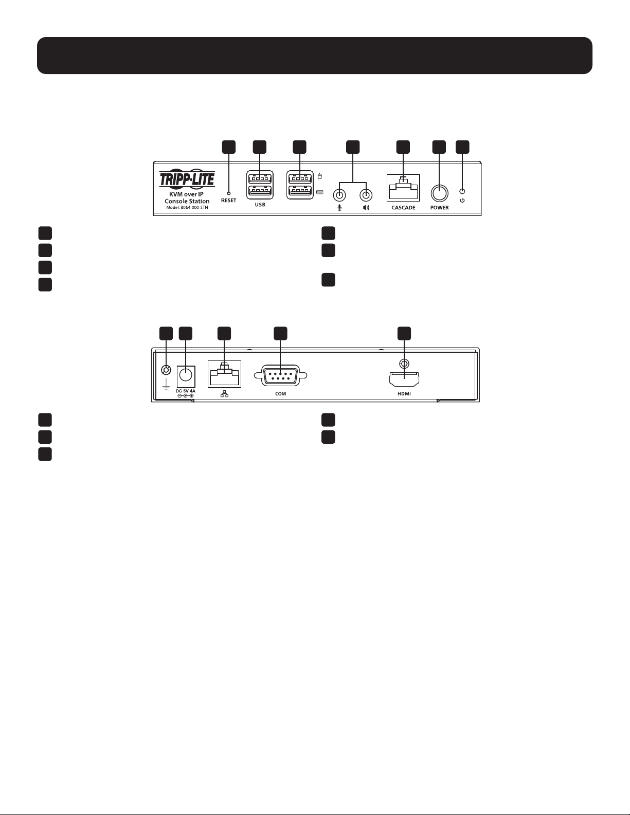
Rear Panel:
1.5 Introduction
Front Panel:
1. Overview
1
Reset Switch
2
USB 2.0 Peripheral Ports
3
USB Keyboard/Mouse Ports
4
Microphone and Speaker Ports
5
Cascade Port
6
Power Button (Press once to enter Standby Mode, press
again to power on the unit)
7
Power LED (Power ON: Blue; Standby: Orange)
1
Ground Terminal
2
DC Power Supply Input
3
LAN Port
4
COM (RS-232) Port
5
HDMI Port
1
1 2 3 4 5
2 3 4 5 6 7
6
2. Setup
2.1 Mounting Instructions
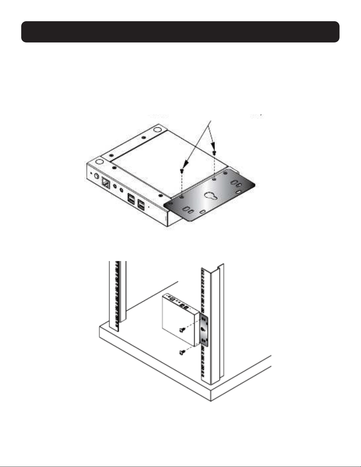
The B064-000-STN can be rack mounted or wall mounted. The following section will guide you through the proper steps.
Rack Mounting
The KVM over IP Console Station is designed to be mounted at the rear of a rack, where it occupies 0U to save space.
1. Remove two bottom screws on the unit. Use the screws to secure the mounting plate to the bottom of the unit as shown in
Figure 1.
Figure 1: Secure Mounting Plate to Unit
2. Screw the mounting plate to any convenient location in the rear of the rack.
Note: These screws are user-supplied. M5 x 12 Phillips type I cross screws are recommended.
Figure 2: Secure Unit to the Rack
M3 x L5 (Countersunk Head)
7
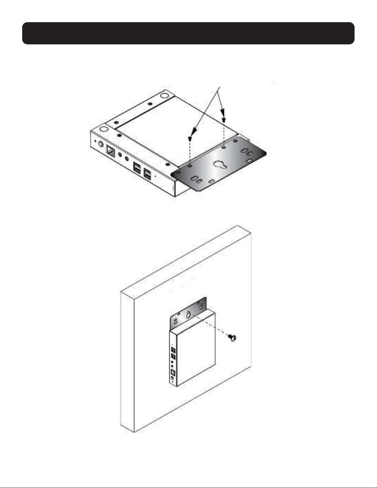
Wall Mounting
1. Remove two bottom screws on the unit. Use the screws to secure the mounting plate to the bottom of the unit.
Figure 3: Secure Mounting Plate to Unit
2. With a user-supplied screw, use the mounting plate’s center screw hole to mount the unit to a wall.
Figure 4: Mounting the Unit to a Wall
2. Setup
M3 x L5 (Countersunk Head)
WALL
8
2. Setup
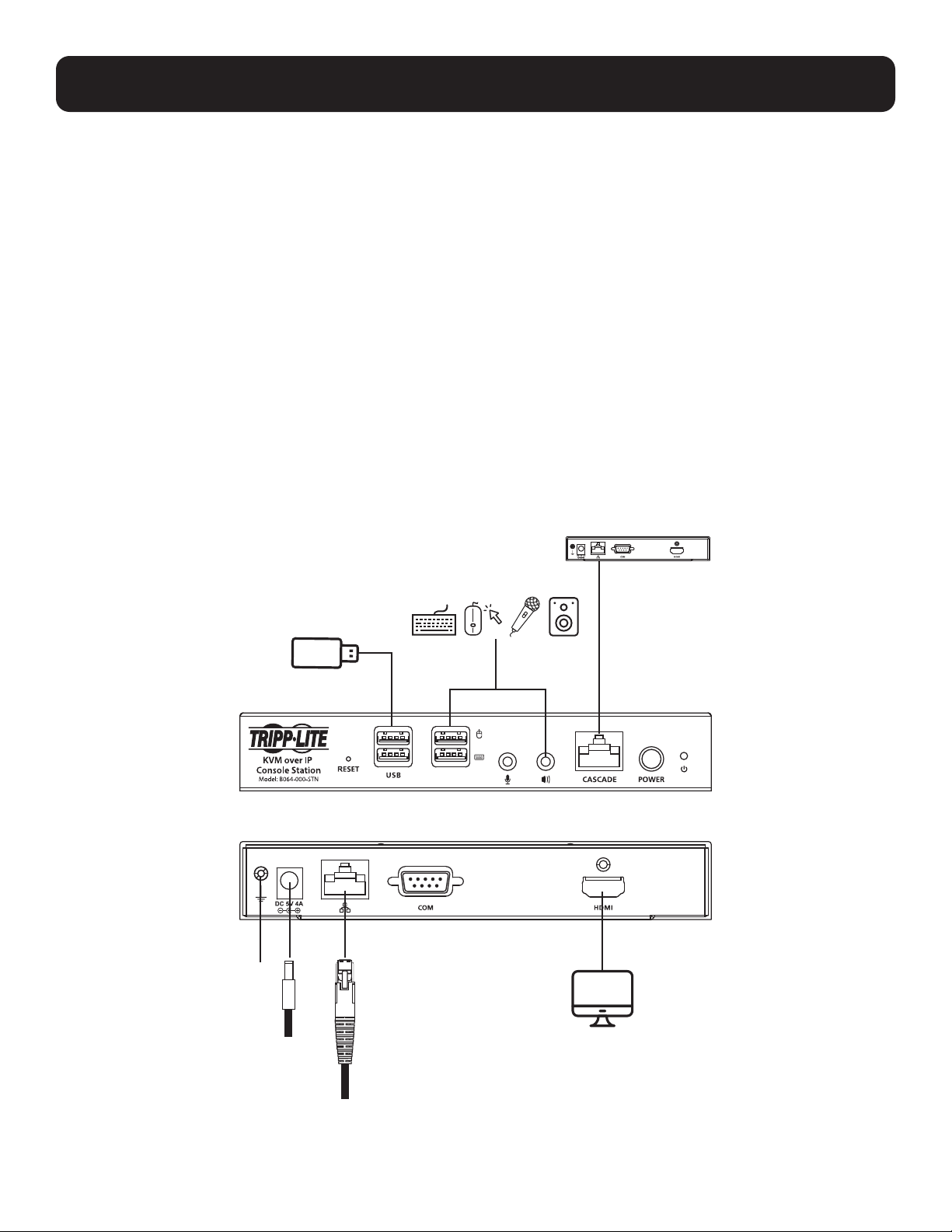
2.2 Installation
The B064-000-STN HDMI KVM over IP Remote User Console Station supports hot-plugging, which allows you to connect,
disconnect, add or remove components without having to shut down the unit. If it becomes necessary to power off the Remote
User Console Station, use the shutdown function, disconnect the power adapter and wait 30 seconds before reconnecting it.
Note: The numbers shown in Figure 5 correspond to the installation steps below.
1. Connect your USB keyboard and USB mouse, as well as any speakers or microphone.
2. With a user-supplied HDMI cable, connect an HDMI display to the HDMI port on the unit.
3. Plug an Ethernet cable from the network into the LAN port.
4. (Optional) Plug USB flash drives or devices into the peripheral USB ports on the front of the unit.
5. (Optional) To cascade an additional B064-000-STN unit, plug one end of a user-supplied Cat5e/6 Ethernet cable into the
port labeled CASCADE on the first stage unit, then plug the other end of the Ethernet cable into the LAN port of a second
stage B064-000-STN unit. The added unit will gain the first stage unit’s internet connection but configuration and control
of each unit is separate.
Note: DO NOT connect the cascade port to a network switch or it will cause a switching loop.
6. (Optional) The unit can be grounded by attaching a grounding wire to the Grounding Terminal, then to a suitable, earth-
grounded object. Note: Grounding wire is not included.
7. Connect the included external power supply to the power jack on the unit.
Figure 5: Installation
1
2
3
4
5
6
7
9
3. Operation
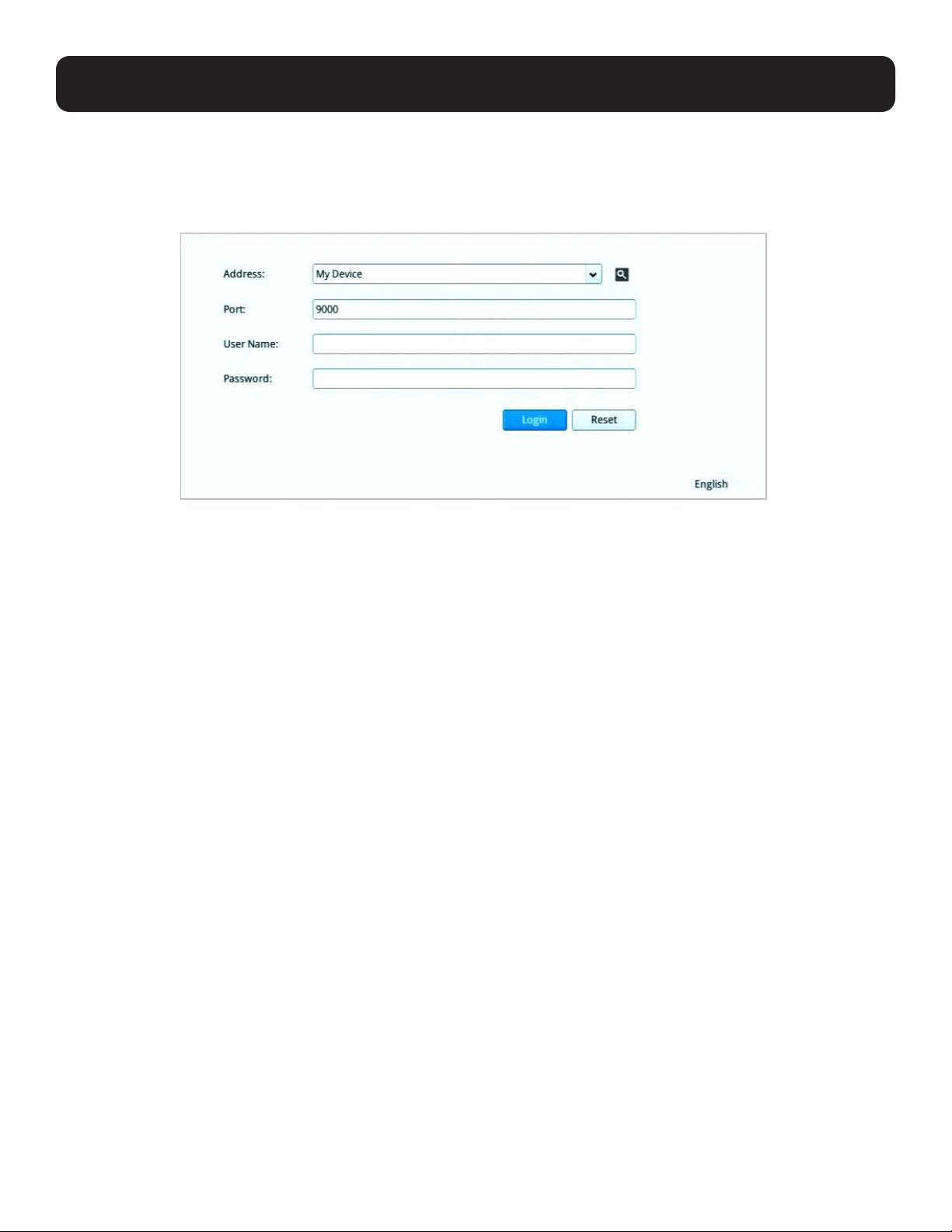
3.1 Logging In
The B064-000-STN is a central control station used to monitor several or all of the B064-IPG-Series KVM switches in
your network. A valid user name and password are required to log in (Figure 6). The default user name and password are
administrator and password, respectively.
Figure 6: Login Screen
If invalid credentials are entered, an Invalid User Name or Password, or Login Failed message will appear. Log in again with the
correct user name and password.
Note: If the number of invalid login attempts is exceeded, a timeout period is invoked. You must wait until the timeout period expires before
attempting to login again.
The B064-000-STN supports two different modes:
• Console Station Mode: Log into the console station (My Device)
• KVM Device Mode: Log into a KVM directly
1. a. To log into the console station (My Device), select My Device from the Address dropdown menu.
b. To log into a KVM device directly, specify the device’s IP address and its port.
Note: To find the addresses of other KVM devices on the same local area network, click the magnifying glass symbol or look in the
Address dropdown menu for a device history list (the device history can be cleared using a terminal command).
2. Enter a user name and password (by default, user name and password are administrator and password, respectively), then
click “Login” to log in.
Note: For security purposes, the user name and password should be changed by the administrator to unique values.
3. At the bottom right-hand corner, a language option is available (English is default). Click to change the language.
10
3. Operation
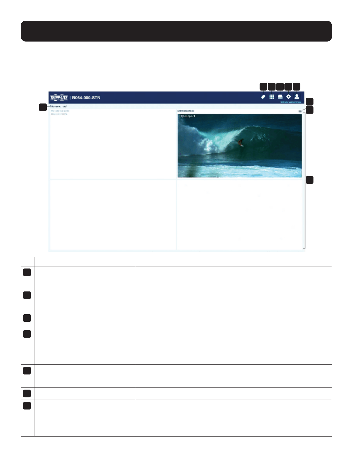
3.2 Dashboard
Once you have successfully logged in, the HDMI KVM over IP Remote User Console Station interface dashboard appears.
Note: The screenshot below depicts an administrator’s page. Depending on the user type and permissions, not all elements will appear.
No. Name Description
1
Tab Management Tab Management allows users to separate KVM over IP switches currently
being monitored into different tab groups or select which tab is to be
displayed.
2
Panel Array Management Panel Array Management allows users to simultaneously display the ports
connected to the KVM over IP switches. The ports can also be grouped into
different groups displaying only the ports in the chosen group simultaneously.
3
Device Management Device Management allows users with administrative access/authority to add
devices to or remove devices from the User Console Station.
4
System Configuration System Configuration allows users with administrative access/authority
to manage users/groups, display device information, configure network,
advanced network management (ANMS), security settings, manage firmware
upgrade, system backup/restore, push/pull configurations to or from other
devices, access terminal or reset system to factory default settings.
5
User Settings User Settings allow users to change password, configure preferences, log out,
restart the system, shut down the system or display quick information about
the user console station.
6
Username Displays the user name.
7
Individual Monitor Option Individual Monitor Option allows users to select which port is to be displayed
on an assigned display, open the GUI or disconnect from the KVM over IP
switch.
If the switch is disconnected, you can also click Reconnect to reconnect the
switch to the console station.
1 2 3 4 5
6
7
8
9
11
3. Operation
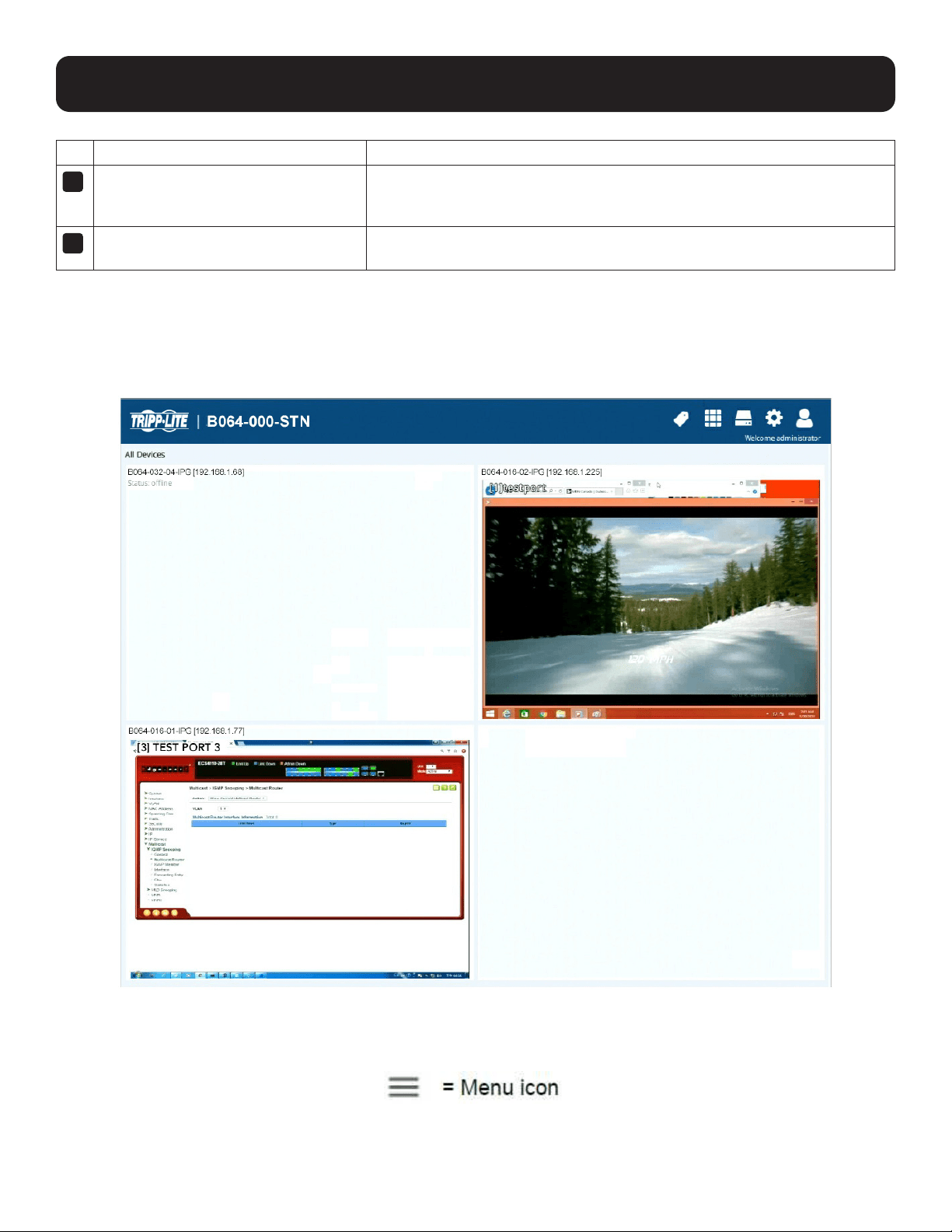
No. Name Description
8
Available KVM over IP Switch Monitor Available KVM over IP Switch Monitor displays the available KVM over IP
switch at a glance. Each monitor will consecutively rotate through the device’s
connected ports.
9
Tab Name Displays the tab name. Clicking the tab name will bring out an option
“Reconnect All Devices”. Click the option for the reconnection operation.
3.3 Dashboard Operation
The dashboard of the Remote User Console Station usually displays the connected devices in an array of monitor units. Each
of the units corresponds to a connected device on its respective KVM over IP switch. The unit will rotate consecutively between
all the connected ports on that KVM over IP switch.
Double-clicking a monitor will bring you to the port’s page.
For individual monitor options for a particular device, move your mouse over its corresponding monitor unit. A menu icon will
be shown on the top right-hand corner of each unit.
12
3. Operation
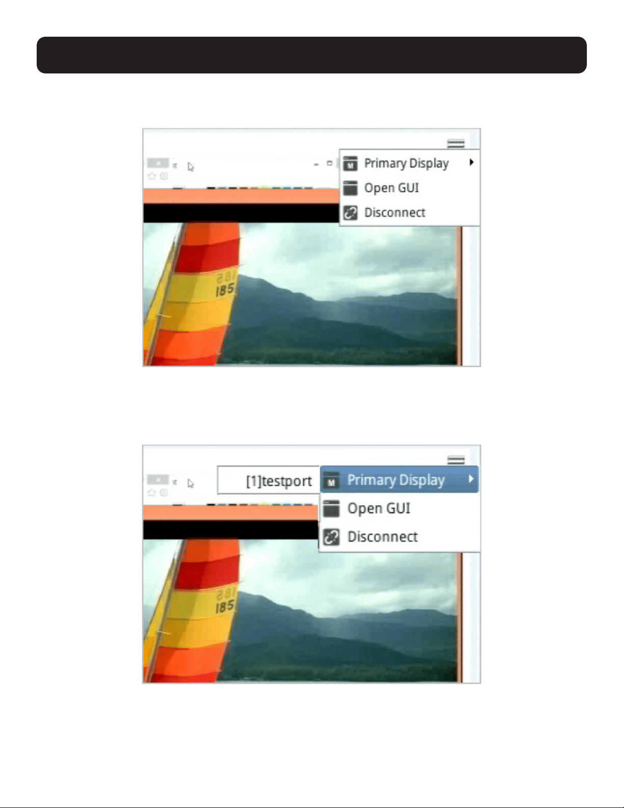
Monitor Unit Option
Click the Menu icon to display the available options:
Primary Display
To display a port on the primary display:
1. Move the mouse over Primary Display and click to select the port. The selected port should now be on the primary display.
Your keyboard and mouse can now also control the server connected to that port.
For control of the server, the HDMI KVM over IP Remote User Console Station’s interface provides a toolbar to help you with
the remote control operations. Refer to section 6. Toolbar Interface.
13
3. Operation
GUI
If you wish to use the KVM over IP switch’s GUI, click “Open GUI”. Refer to the B064 KVM switch’s Owner’s Manual for GUI
operation instructions.
Disconnect
Click “Disconnect” to disconnect from this KVM switch device.
Reconnect
Click “Reconnect” to reconnect to an offline KVM switch device.
3.4 Tab/Panel Array Display and Management
Tab management allows users to separate KVM over IP switches currently being monitored into different groups or select which
tab group is to be displayed on the dashboard.
Panel array management allows users to separate available ports into different groups or select which panel array group is to
be displayed on the panel array page.
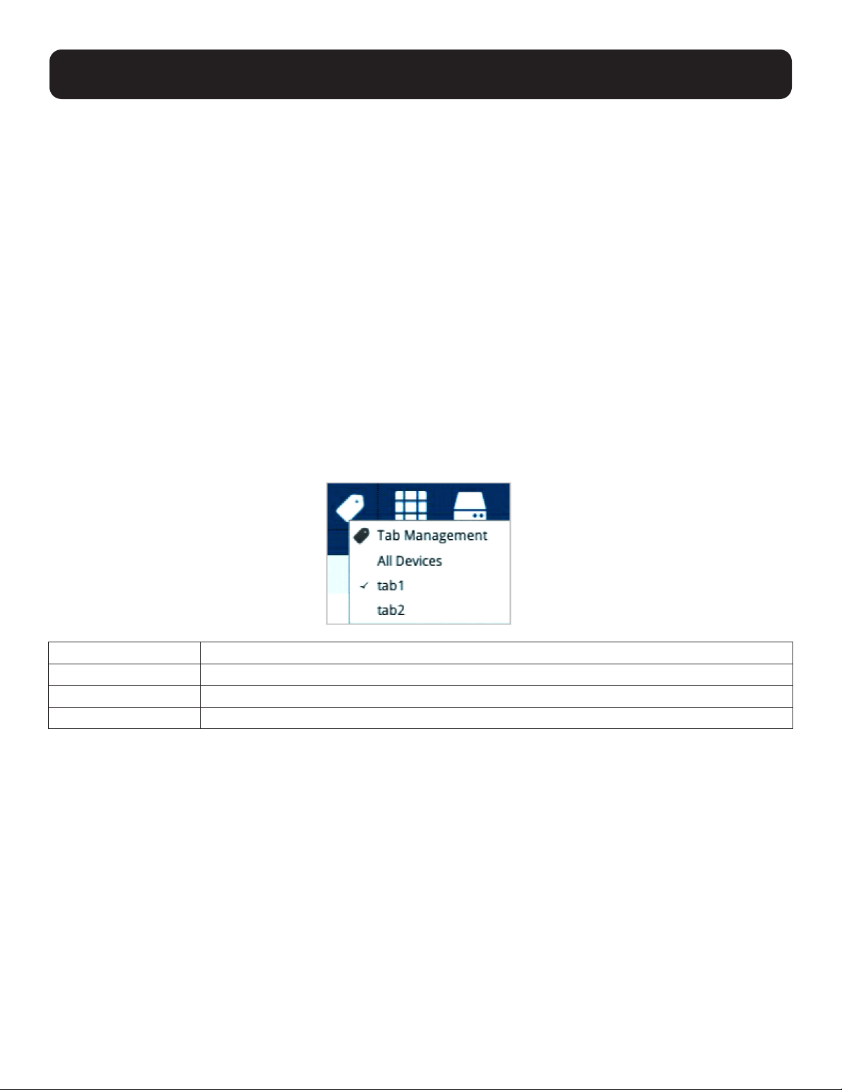
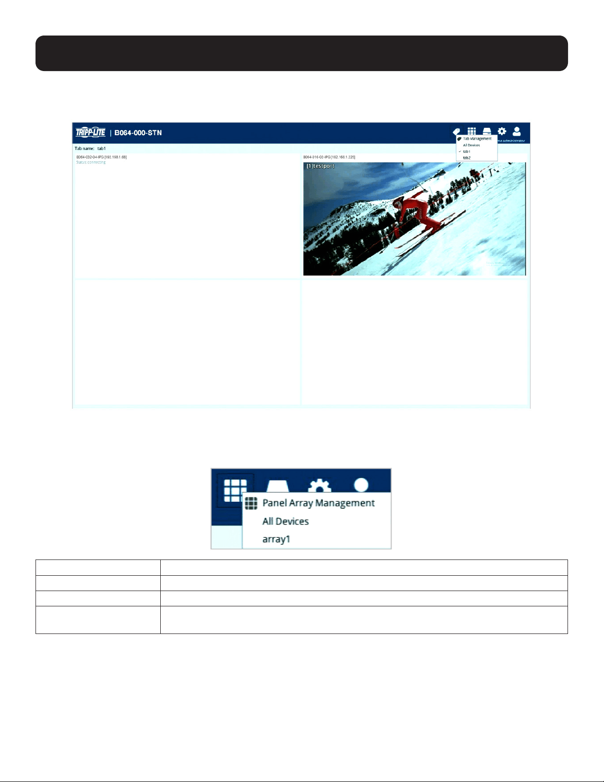
3.4.1 Tab Options
Click the Tab icon to display the tab options.
Option Description
Tab Management Click this option to add, delete or modify tabs (groups).
All Devices Click this option to display all the connected KVM over IP switches on the dashboard.
Created Tabs Select a created tab to display the KVM over IP switches in the tab on the dashboard.
14
Tab Display
Following is an example showing the KVM of IP switches in a tab displayed on the dashboard (tab1 selected):
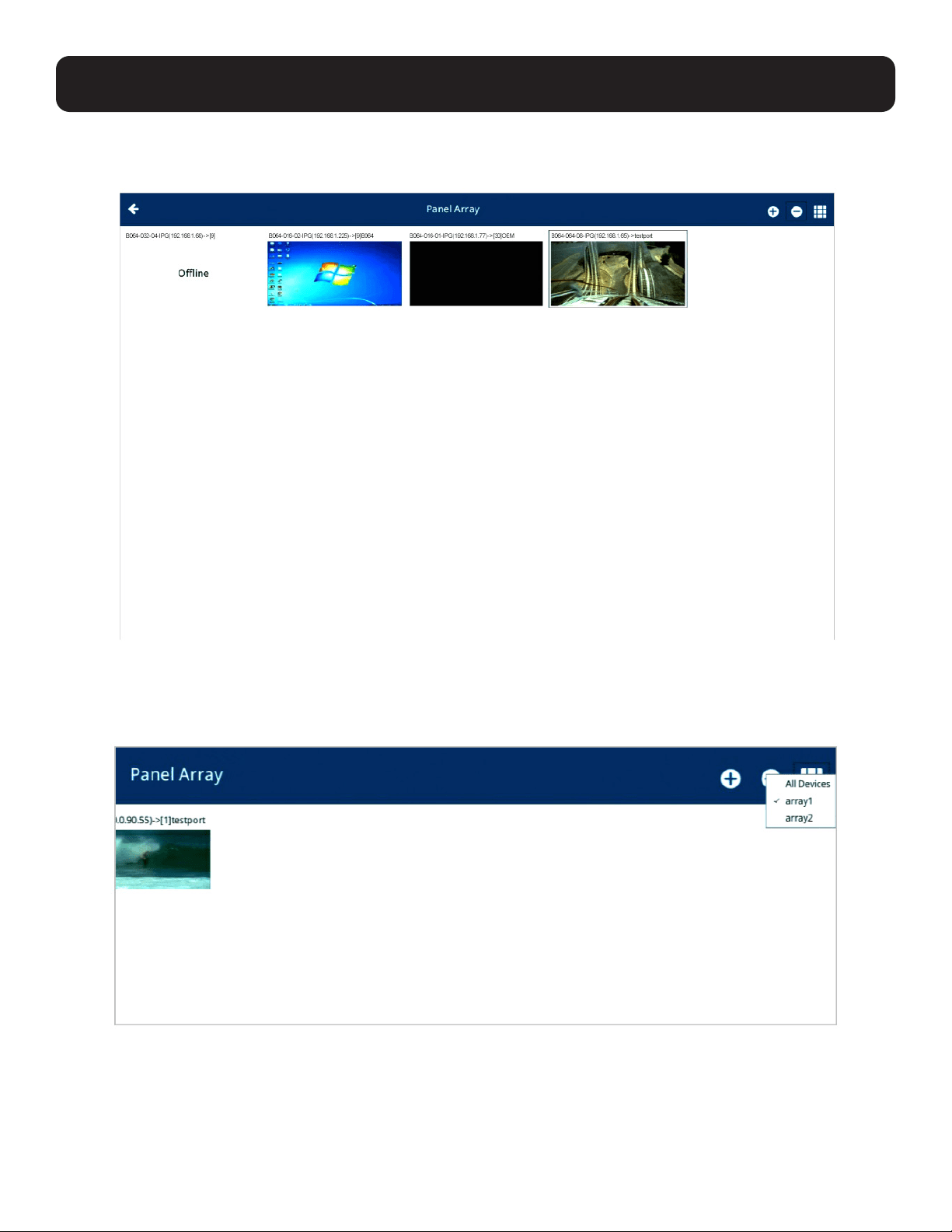
3.4.2 Panel Array Options
Click the Panel Array icon to display the panel array options:
Option Description
Panel Array Management This option allows you to add, delete or modify panel array (groups).
All Devices All the ports of connected KVM over IP switches are displayed on the panel array page.
Created Panel Arrays Select a created panel array. All the ports connected to the KVM over IP switches in the panel
array are displayed on the panel array page.
Note: Audio is not supported.
3. Operation
15
3. Operation
Panel Array Display
Following is an example showing the ports of connected KVM over IP switches in a panel array displayed (array1 selected):
Press the + icon to display more device ports (up to 64 ports) on a smaller scale. Press the - icon to display fewer device
ports on a larger scale.
The panel array icon is also shown on the top right-hand corner of the panel array page. Clicking it allows you to select which
array you want to display, or display all device ports:
Click the back arrow to return to the dashboard.

16
3.4.3 Tab/Panel Array Management
Click the Tab or Panel Array icon to show their corresponding options. Due to their similarity, tab management is used as the
example below. Click “Tab Management” (or “Panel Array Management”) for the following page:
This page allows you to add/edit/delete tabs.
3. Operation
17
3. Operation
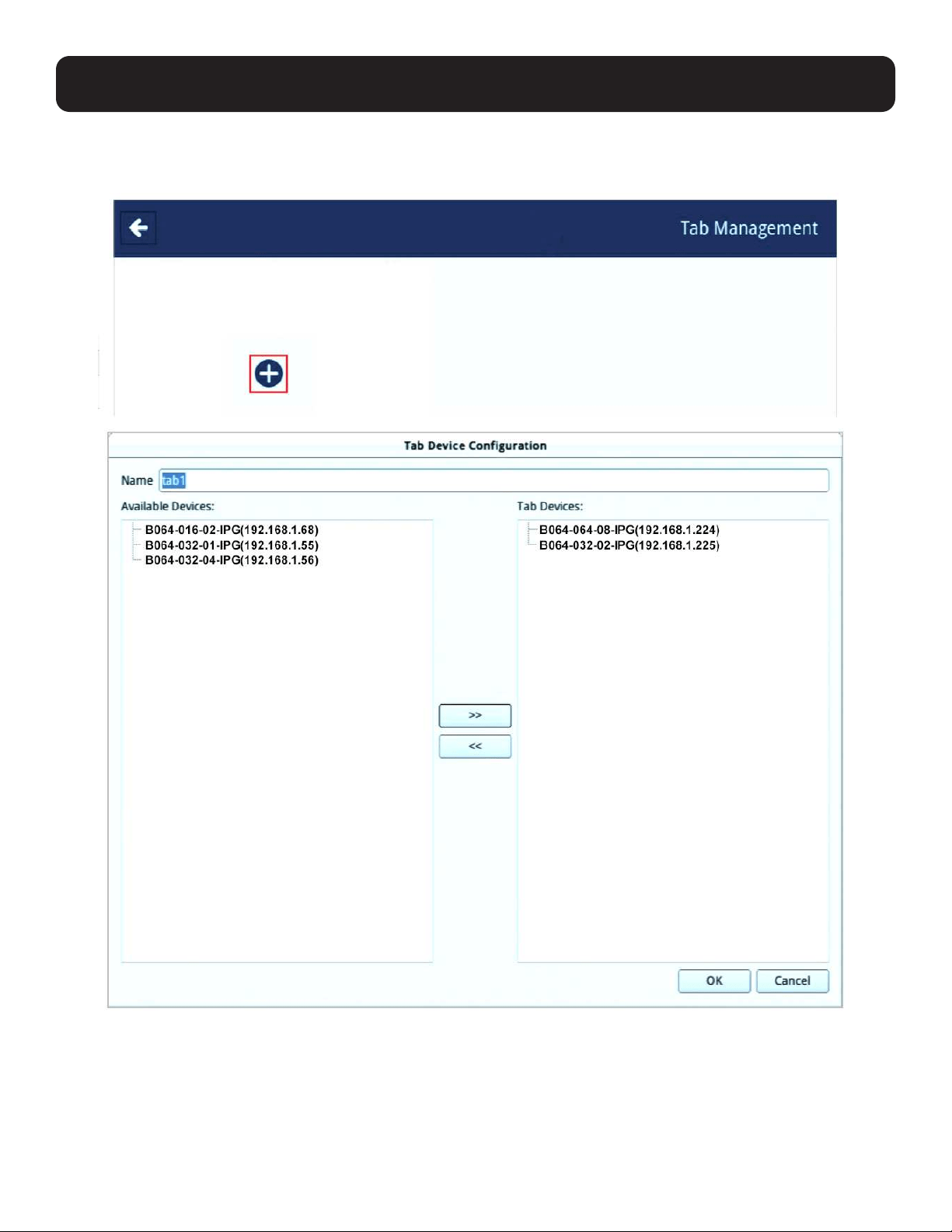
3.4.4 Adding a Tab
1. To add a tab, click the + icon. A new window (Tab Device Configuration) will be displayed.
2. Enter a name for the new tab.
3. Click on the devices you wish to be in this tab group and click the >> button.
18
3. Operation
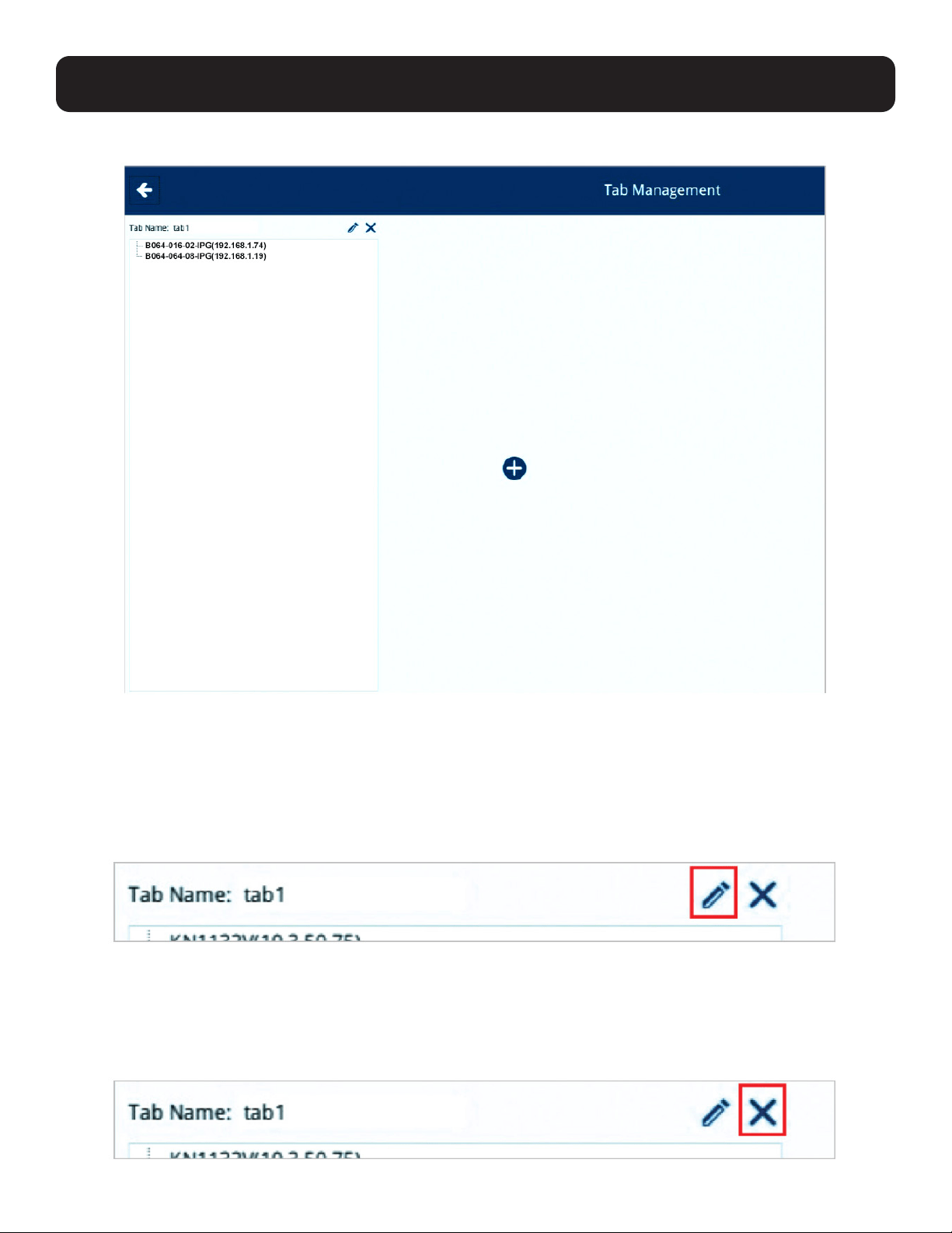
4. Click the “OK” button when done. The tab will be shown:
3.4.5 Adding Another Tab
To add another tab, click the + icon again and follow the steps outlined in section 3.4.4 Adding a Tab.
3.4.6 Editing a Tab
To edit a tab, click the pen icon beside Tab Name.
The Tab Device Configuration window will be displayed as in Adding a Tab.
Edit its name, shift the devices around using the >> or << icons and click “OK” when done.
3.4.7 Deleting a Tab
To delete a tab, click the “X” icon beside Tab Name.
19
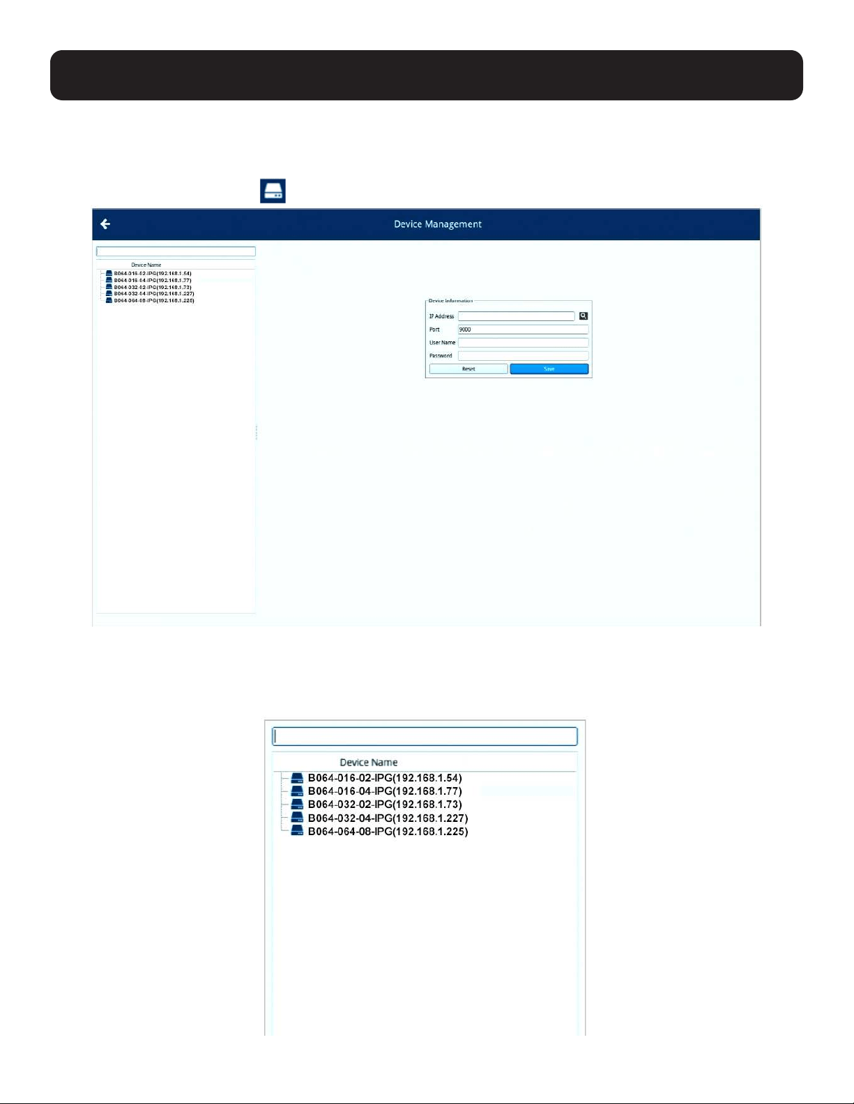
4. Device Management
Device management enables users with administrative access/authority to add devices to or remove devices from the
B064-000-STN. The KVM over IP Remote User Console Station can manage up to 256 KVM over IP switches and is able to
display snapshots of up to 16 devices.
Click the Device Management icon
to enter its main page.
4.1 Device List
The feature on the left of the Device Management page is the device list.
20
4. Device Management
4.1.1 Search
The rectangular field at the top is the search function. Enter the IP address of the device you want to search for to find that
device.
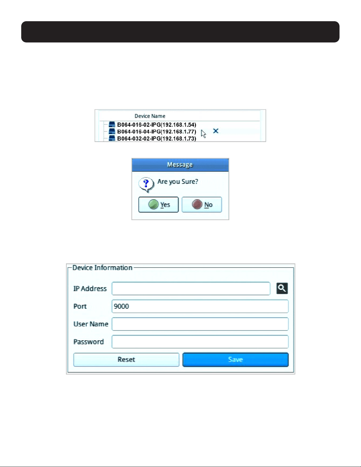
4.1.2 Removing a Device
To remove a device from the list, hover your mouse over the device. An X icon will be displayed.
Click the X icon to remove the device. The system will ask for confirmation.
Click “Yes” to proceed or “No” to cancel the action.
4.1.3 Adding a Device
The feature in the middle of the Device Management page enables the user to add devices to the system.
21
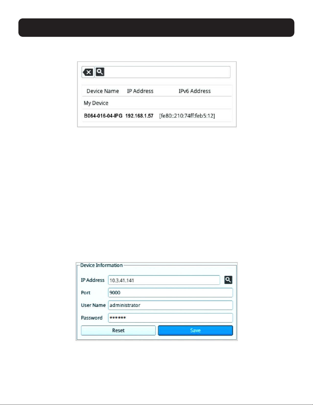
4. Device Management
Hover your mouse over the search button (magnifying glass). A list of KVM control unit device(s) on the same local area
network (LAN) will be shown:
Select the desired device or enter an IP address of a known device; enter a user name and password, and click “Save” to add
the device to the system.
Notes:
1. The entered user name and password will determine the access rights of the KVM over IP Console Station.
2. To gain full access rights of the KVM switch device, use the user name and password of a user with full access rights.
3. If you select the desired device by clicking the “Device Name” or “IP Address” sections, the displayed name will show the IPv4 address.
The IPv6 Address will be displayed when clicking the “IPv6 Address” section.
4. If a KVM over IP Switch is also added to NetDirector-AXS and has “Disable Other Authentication” configured in NetDirector-AXS, the KVM
over IP Console Station will not be able to access/control that switch.
Click “Reset” if you wish to reenter the information.
The system will attempt to connect to the device. If successful, the device will be listed in the device list.
4.1.4 Changing Connection Information
To change the access rights of a device connected to the KVM over IP Console Station, change to a user with the desired
access rights:
1. Select the device from the device list.
2. Edit the settings in the Device Information section:
3. Click “Save” to update the information.
4. Log out of the KVM over IP Console Station and log in again to see the updated settings/display/access rights.
22
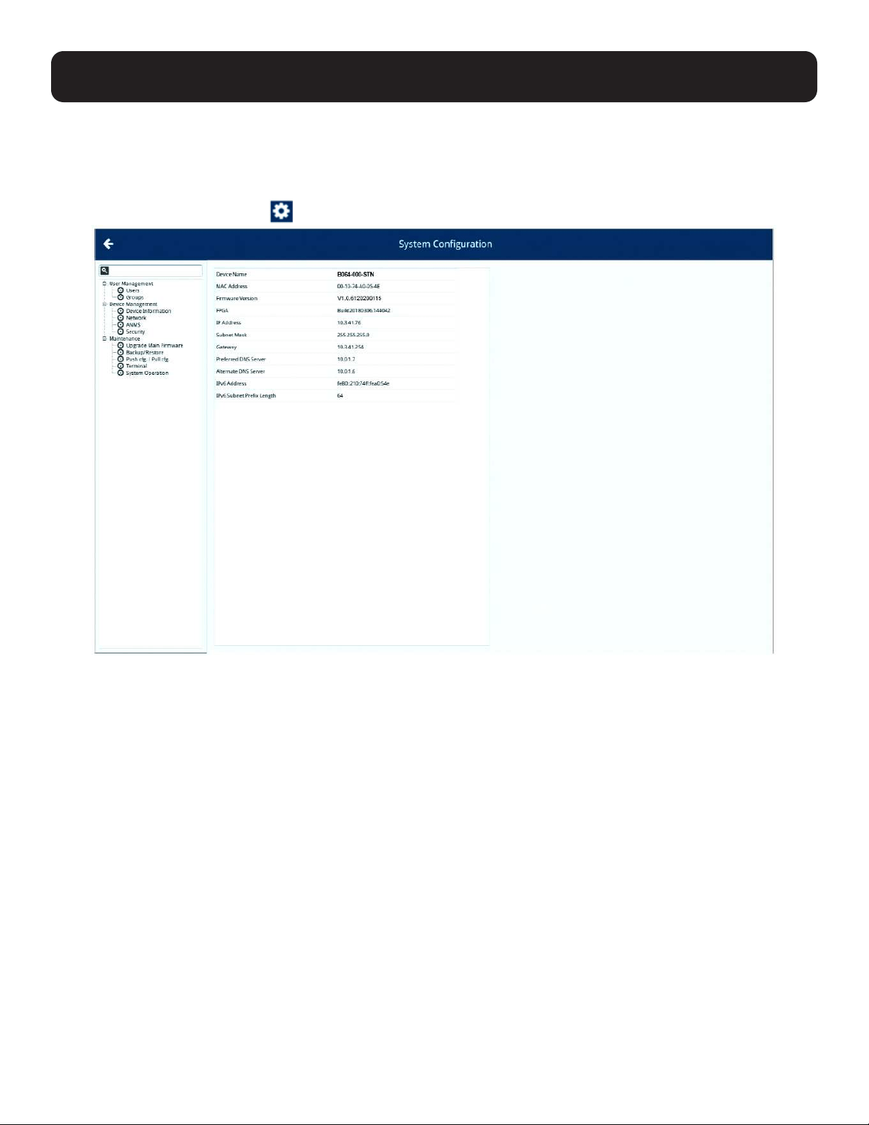
5. System Configuration
System configuration enables users with administrative authority to manage users or groups, display device information,
configure network, advanced network management (ANMS) or security settings, or manage firmware upgrades, system
backup/restore, push/pull configurations to or from other devices, access terminal, or reset the system to factory default
settings.
Click the System Configuration icon
to enter its main page.
The page consists of a left-hand side menu and a right-hand side information/configuration body.
By default, device information is displayed upon entering system configuration page as shown above.
If an item in the side menu has a + or - symbol, a submenu is available when expanded. Expand the submenu by clicking the
+ symbol. Collapse the submenu by clicking the - symbol.
5.1 User Management
This section allows you to manage users and groups.
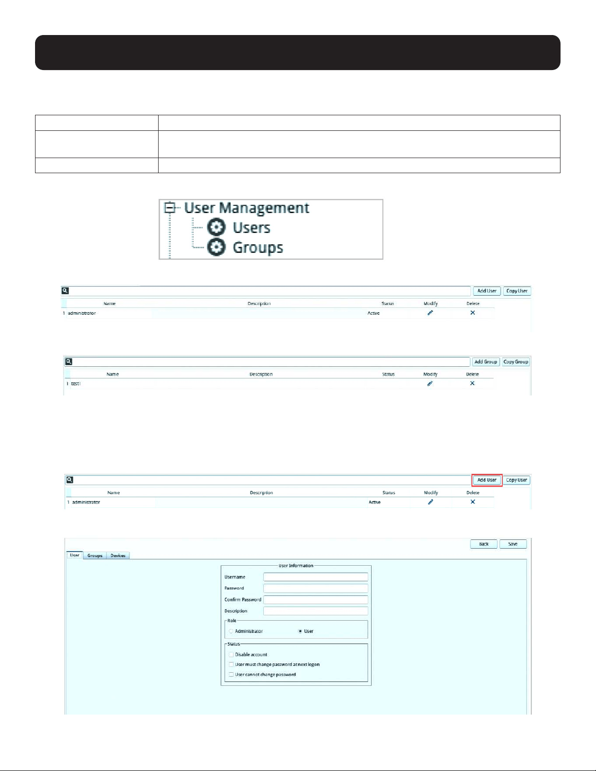
5.1.1 Users and Groups
Groups enable administrators to easily and efficiently manage users and devices. Because device access rights apply to
anyone who is a member of the group, administrators need only set them once for the group, instead of setting them for each
user individually. Multiple groups can be defined to allow some users access to specific devices, while restricting other users
from accessing them.
23
5. System Configuration
The KVM over IP Console Station supports two privilege categories determined by “User Types”. User types are selected during
user creation. The descriptions are shown in the following table:
User Types Role
Administrator Access and manage devices. Manage users and groups. Configure the overall installation.
Configure personal working environment.
User Access authorized devices. Configure personal working environment.
Click “Users” or “Groups” under “User Management” in the left-hand side menu to bring up the respective configuration page.
User Page
Group Page
5.1.1.1 Add User
Because the management of users and groups are very similar, User is the example used in the operations below.
To add a user:
1. Click “Add User” on the top right-hand corner of the page.
The following will be displayed:
24
5. System Configuration
2. Enter the required information in the appropriate fields. A description of the required user fields is given in the following
table:
Field Description
Username 1 to 32 characters are allowed depending on the Account Policy settings (refer to section
5.2.4.2 Account Policy).
Password 0 to 32 characters are allowed depending on the Account Policy settings (refer to section
5.2.4.2 Account Policy).
Confirm Password Reenter the password to ensure there are no mistakes. The two entries must match.
Description Additional information about the user you may wish to include.
Role There are two categories: Administrator and User. There is no limit on the number of accounts
that can be created in each category.
The Administrator is responsible for the overall installation configuration and maintenance, user
management and device assignments.
Each user assigned to administrator role will have privileges to add KVM over IP switches by
default.
Refer to section 5.1.2.1 Using User Configuration Page.
Status Status allows you to control the user’s account and access to the installation, as follows:
• Disable Account lets you suspend a user’s account without actually deleting it, so that it can
be easily reinstated in the future.
• To require a user to change their password at the next log on, select “User must change
password at next logon”. This can be used by the administrator to give the user a temporary
password to log in for the first time, and then let the user set their password of choice for
future logins.
• To make a password permanent, so that the user cannot change it to something else, select
“User cannot change password”.
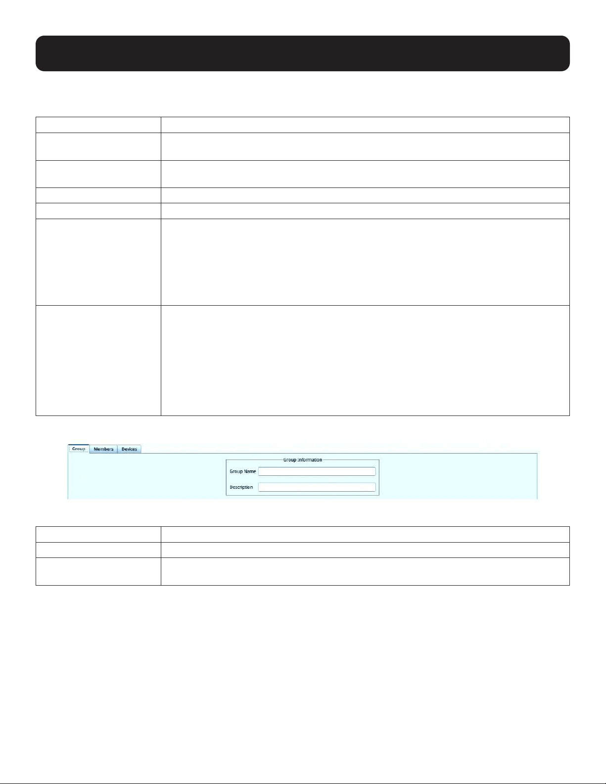
If you choose Groups in the left-hand side menu, click Add Group to bring up the following page:
A description of the required fields is given in the following table:
Field Description
Group Name Up to 32 characters are allowed.
Description Additional information about the user group you wish to include, to a maximum of 45
characters.
3. You can assign the new user to a group by selecting the Groups tab (refer to section 5.1.2.2 Using Group Configuration
Page). You can also assign the user’s port access rights by selecting the Devices tab (refer to section 5.1.3.1 Using
Device Configuration Page).
Note: Optionally, you can skip this step now to add more users and create groups, and come back to it later.
4. When your selections have been made, click Save.
5. When the Operation Succeeded message appears, click OK.
25
5. System Configuration
Click Back on the top right-hand corner of the configuration body or click Users in the left-hand side menu to return to the
User Management page. The newly added user will appear in the configuration body.
• The information/configuration body shows the user name, the description that was given when the account was created,
whether the account is currently active or has been disabled and gives the option to modify or delete the user.
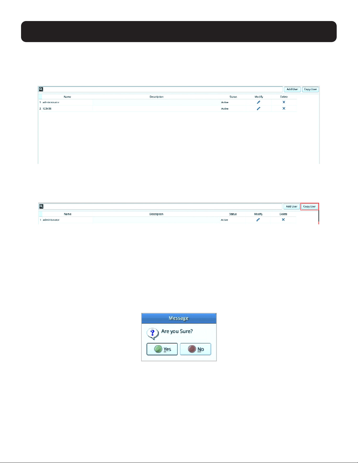
5.1.1.2 Copy User
To save time creating a user with similar settings/information, use the Copy User function. A “Copy User” button is shown on
the top right-hand corner of the configuration body.
Select the user you want to copy and click the “Copy User” button; follow the information in Add User to complete the
configuration.
5.1.1.3 Modify User
To modify the user’s information, click the pen icon under the “Modify” column of the information/configuration body.
For configurable fields, refer to Add User above.
5.1.1.4 Delete User
If you wish to delete a user, click the X icon under the “Delete” column of the information/configuration body.
The system will ask for confirmation:
Click “Yes” to proceed, or “No” to cancel action.
26
5. System Configuration
5.1.2 Managing (Assigning) Users and Groups
There are two ways to assign users to groups: from the Users configuration page and from the Group configuration page.
Note: Before you can assign users to groups, you must first create them. See Add User for details.
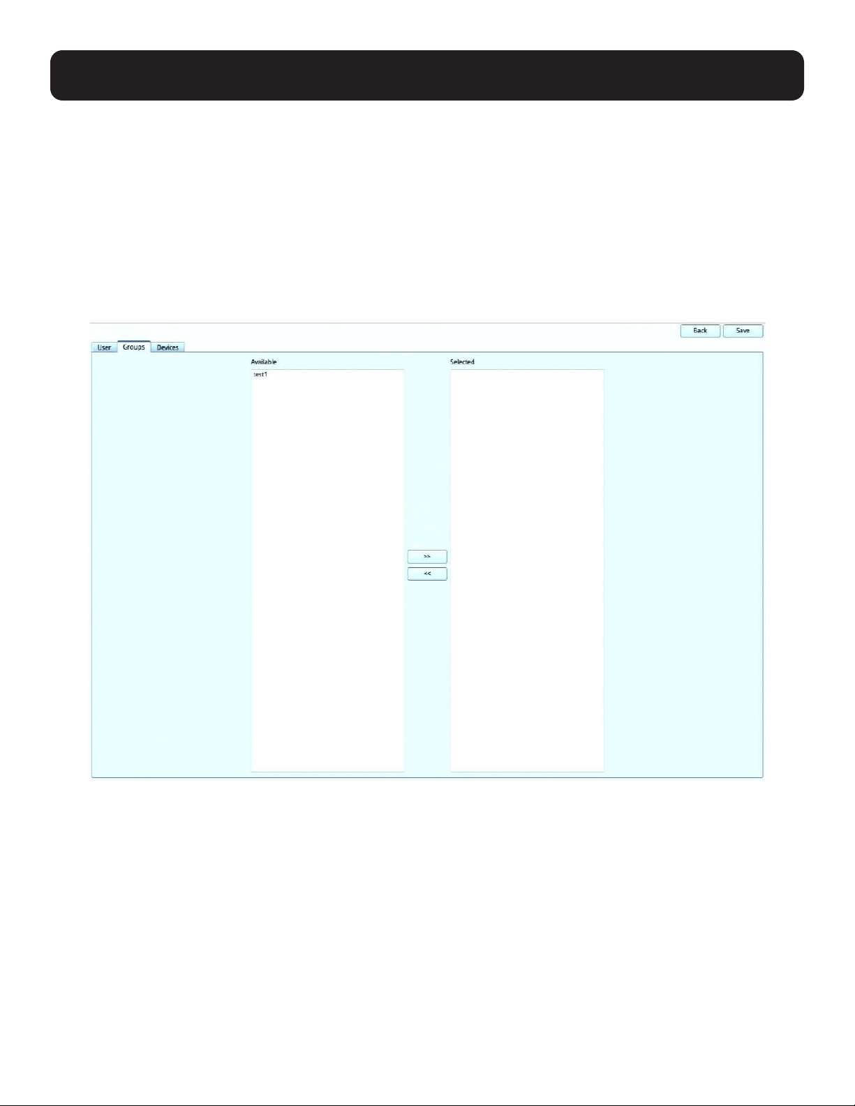
5.1.2.1 Using User Configuration Page
Follow the steps below to go to the User’s configuration page:
1. Click “Users” under “User Management” in the left-hand side menu to bring up the configuration page.
2. Click the pen icon under the “Modify” column.
3. In the configuration page, select the Groups tab:
Assign a User to a Group
1. In the Available column, select the group you want the user to be in.
2. Click the >> icon button to put the group’s name into the Selected column to add the user to group.
3. Repeat the above for any other groups you want the user to be in.
4. Click “Save” when you are done.
Remove Users from a Group
1. In the Selected column, select the group you want the user to be removed from.
2. Click the << icon button to remove the group’s name from the Selected column to remove the user from the group.
3. Repeat the above for any other groups you want the user to be removed from.
4. Click “Save” when you are done.
27
5. System Configuration
5.1.2.2 Using Group Configuration Page
Follow the steps below to go to the Group’s configuration page:
1. Click “Groups” under “User Management” in the left-hand side menu to bring up the configuration page.
2. Click the pen icon under the “Modify” column.
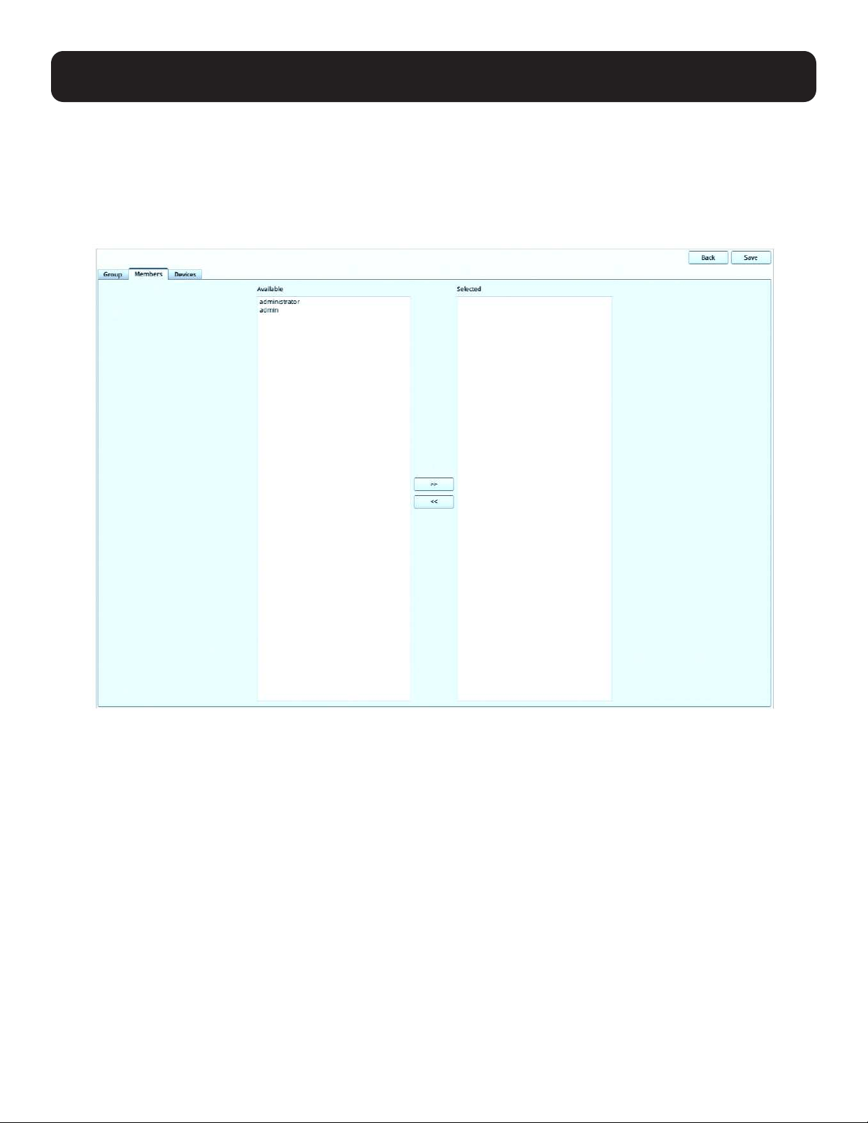
3. In the configuration page, select the Members tab as shown:
Assign Users to a Group
1. In the Available column, select the members (users) that you want the group to have.
2. Click the >> icon button to put the members into the Selected column (thereby adding into the group).
3. Repeat the above to assign members to each group.
4. Click “Save” when you are done.
Remove Users from a Group
1. In the Selected column, select the members (users) to be removed from the group.
2. Click the << icon button to put the members into the Available column (thereby removing from the group).
3. Repeat the above to remove members from each group.
4. Click “Save” when you are done.
28
5. System Configuration
5.1.3 Device Assignment
This function assigns access rights to users or groups and can be achieved from Device configuration page. Administrators can
assign users to a particular user’s privileges of an added KVM over IP Switch and access ports.
5.1.3.1 Using Device Configuration Page
Follow the steps below to go to the User’s configuration page:
1. Click “Users” under “User Management” in the left-hand side menu to bring up the configuration page.
2. Click the pen icon under the “Modify” column.
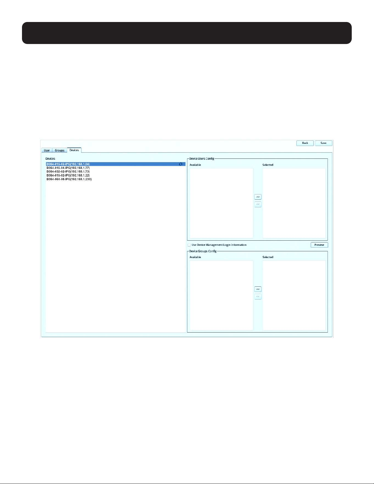
3. In the configuration page, select the Device tab as shown:
Each of the elements on this page is described below.
Devices
• The list displays the currently available device(s).
• When there is a change in the user accounts and groups for a device, click the “Refresh” icon to refresh the user list of that
device.
Device Users Config
• After selecting a device, the Available column (left column) lists the available users (of the device).
• The Selected column (right column) shows the selected user (of the device).
• Click the >> or << icon buttons to shift between Available and Selected.
• The user/group of the console station will gain the permission of the selected user (of the device).
• Each KVM over IP console station user can only be assigned to one user account privilege of the KVM over IP switch device.
29
5. System Configuration
Device Group Config
• After selecting a device, the Available column (left column) lists the available groups (of the device).
• The Selected column (right column) shows the selected groups (of the device).
• Click the >> or << icon buttons to shift between Available and Selected.
• The user/group of the console station will gain the permission of the selected groups (of the device).
User Device Management Login Information
• Checking this will block all selections in the Device Users Configuration and Device Groups Configuration sections, and grant
the access rights of the user used to add this device.
• Refer to section 4.1.3 Adding a Device for details on access rights.
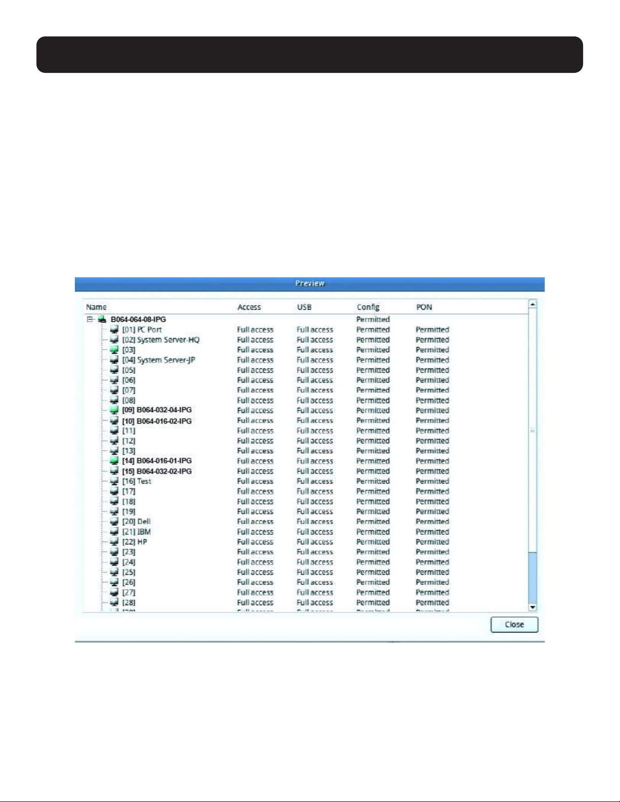
Preview
• Clicking this button will show the access rights of the above selections as in the following example:
30
5. System Configuration
5.2 Device Management
This screen shows device information and allows you to configure network, ANMS and security settings.
Note: Whenever a new setting is saved, the system will reboot.
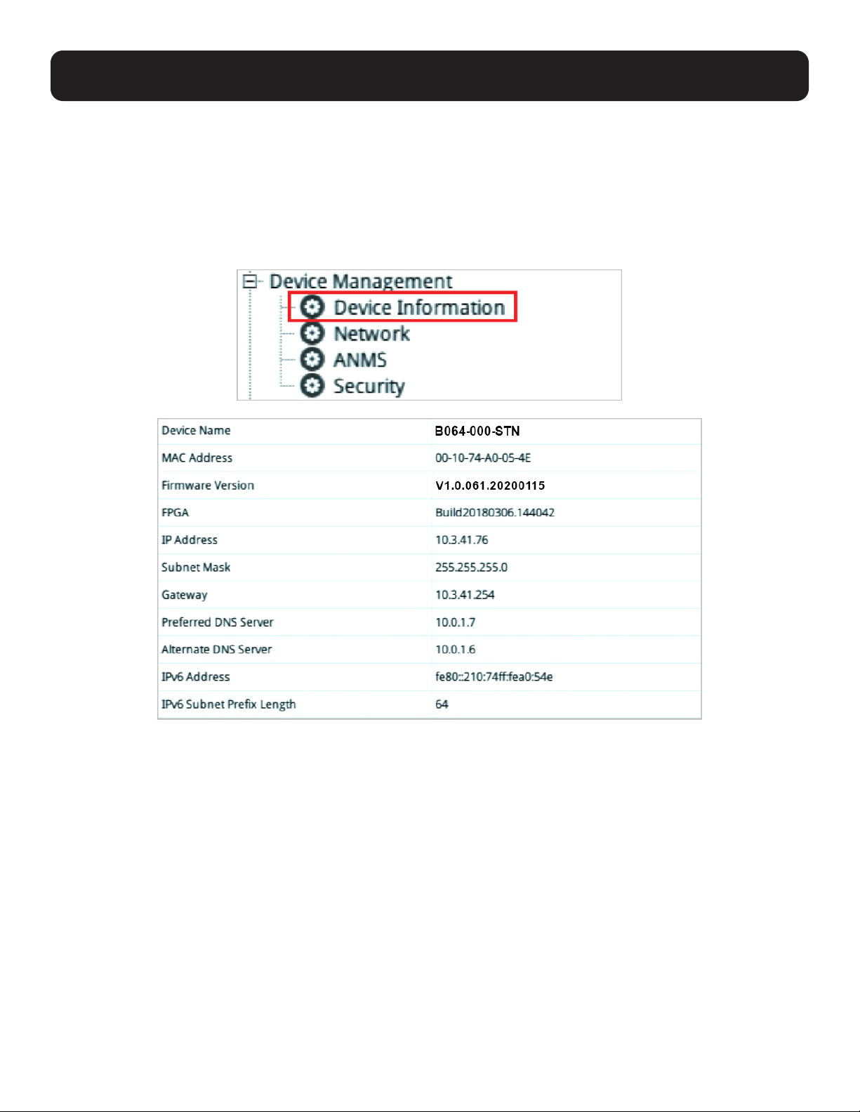
5.2.1 Device Information
Click “Device” under “Device Management” in the left-hand menu to bring up the information page.
The Device Information page displays the name of the selected device, its firmware version, the FPGA (Field-Programmable-
Gate-Array) and information about its network configuration.
Double-click the Device Name (B064-032-02-IPG in the example) to change the device name.
31
5. System Configuration
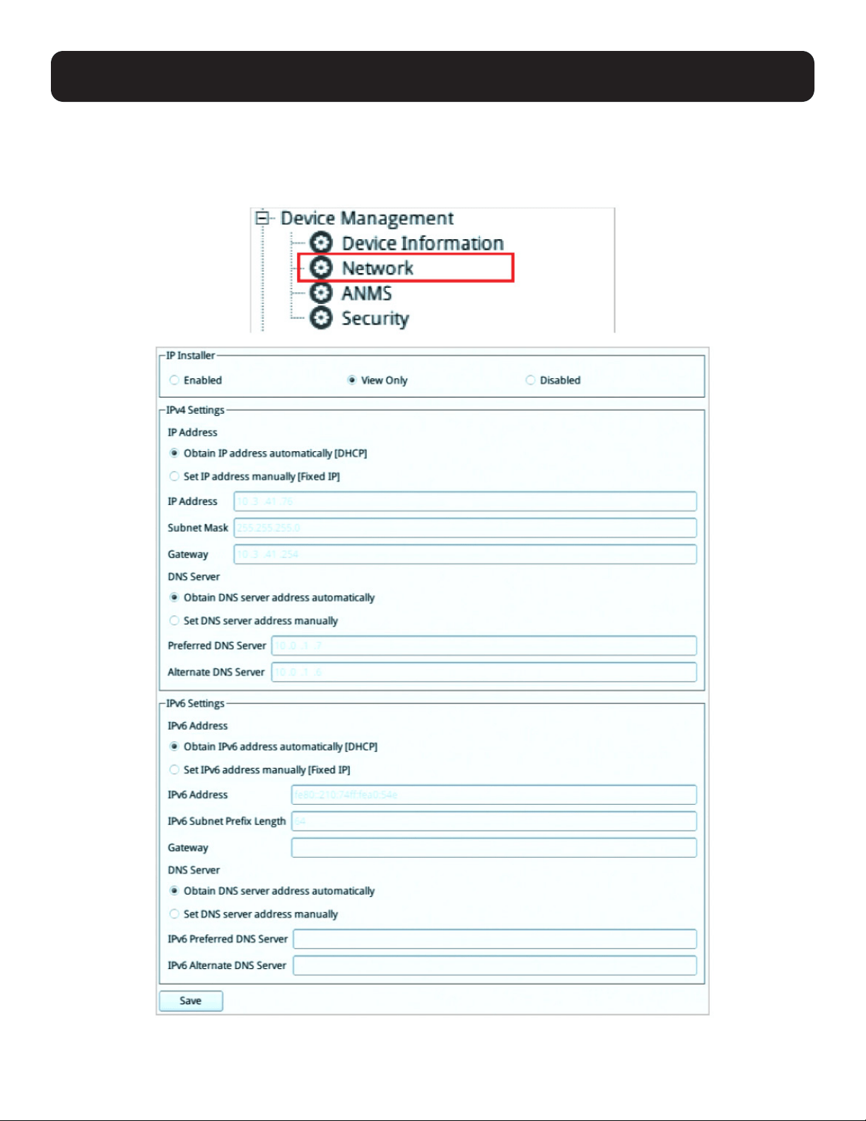
5.2.2 Network
The Network page is used to specify the network environment.
Click “Network” under “Device Management” in the left-hand menu to bring up the information page.
Each of the elements on this page is described below.

32
5. System Configuration
5.2.2.1 IP Installer
The IP Installer is an external Windows-based utility for assigning IP addresses to the KVM over IP switch.
Click one of the radio buttons to select Enable, View Only, or Disabled for the IP Installer utility.
Notes:
1. If you select View Only, you will be able to see the KVM over IP switch in the IP Installer’s Device List, but you will not be able to change
the IP address.
2. For security, we strongly recommend that you set this to View Only or Disable after each use.
5.2.2.2 IPv4 Settings
IP Address:
IPv4 is the traditional method of specifying IP addresses. The KVM over IP Console Station can either have its IP address
assigned dynamically (DHCP), or it can be given a fixed IP address.
• For dynamic IP address assignment, select Obtain IP address automatically (default).
• To specify a fixed IP address, select Set IP address manually and fill in the fields with values appropriate for your network.
Notes:
1. If you choose Obtain IP address automatically, when the console station starts up, it waits to get its IP address from the DHCP server. If it
has not obtained the address after one minute, it automatically reverts to its factory default IP address (192.168.0.60.)
2. If the switch is on a network that uses DHCP to assign network addresses, and you need to ascertain its IP address, see Supported KVM
Switches for information.
DNS Server
• For automatic DNS Server address assignment, select Obtain DNS Server address automatically.
• To specify the DNS Server address manually, select Set DNS server address manually, and fill in the addresses for the
Preferred and Alternate DNS servers with values appropriate for your network.
Note: Specifying the Alternate DNS Server address is optional.
5.2.2.3 IPv6 Settings
The KVM over IP console station supports three IPv6 address protocols: Link Local IPv6 Address, IPv6 Stateless
Autoconfiguration and Stateful Autoconfiguration (DHCPv6).
IP Address:
IPv6 is the 128-bit format for specifying IP addresses. The KVM over IP Console Station can either have its IPv6 address
assigned dynamically (DHCP), or it can be given a fixed IP address.
• For dynamic IP address assignment, select Obtain IP address automatically (default).
• To specify a fixed IP address, select Set IP address manually and fill in the fields with values appropriate for your network.
DNS Server
• For automatic DNS Server address assignment, select Obtain DNS Server address automatically.
• To specify the DNS Server address manually, select Set DNS server address manually, and fill in the addresses for the
Preferred and Alternate DNS servers with values appropriate for your network.
Note: Specifying the Alternate DNS Server address is optional.
5.2.2.4 Finishing Up
After making any network changes, be sure to click “Save” at the bottom of the configuration page.
33
5. System Configuration
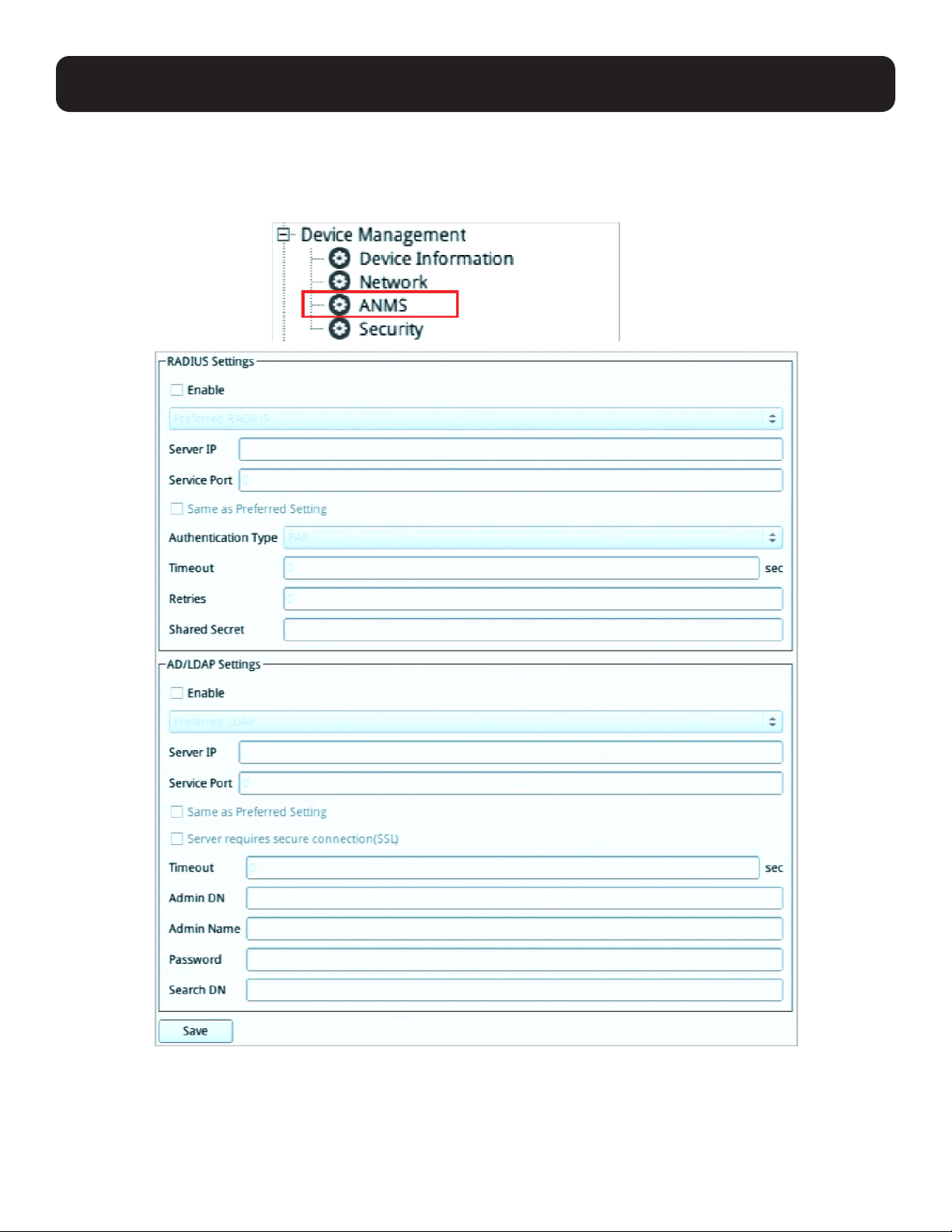
5.2.3 ANMS (Advanced Network Management Settings)
The ANMS page is used to set up login authentication and authorization management from external sources.
Click “ANMS” under “Device Management” in the left-hand menu to bring up the information page.

34
5. System Configuration
5.2.3.1 RADIUS Settings
To allow authentication and authorization for the KVM over IP Console Station through a RADIUS server, perform the following:
1. Check Enable.
2. Select Preferred or Alternate RADIUS server.
3. Fill in the IP addresses and service port numbers for the Preferred and Alternate RADIUS servers. You can use the IPv4
address, the IPv6 address or the domain name in the IP fields.
4. Select the Authentication Type: PAP or CHAP.
5. In the Timeout field, set the time in seconds that the KVM over IP console station waits for a RADIUS server reply before it
times out.
6. In the Retries field, set the number of allowed RADIUS retries.
7. In the Shared Secret field, key in the character string that you want to use for authentication between the KVM over IP
console station and the RADIUS Server. A minimum of 6 characters is required.
8. On the RADIUS server, Users can be authenticated with any of the following methods:
• Set the entry for the user as su/xxxx, where xxxx represents the Username given to the user when the account was created
on the KVM over IP console station.
• Use the same Username on both the RADIUS server and the KVM over IP Console Station.
• Use the same Username name on both the RADIUS server and the KVM over IP console station.
In each case, the user’s access rights are the ones assigned that were assigned when the User of Group was created on the
KVM over IP console station (see section 4.1.3 Adding a Device).
5.2.3.2 AD/LDAP Settings
To allow authentication and authorization for the KVM over IP Console Station via AD/LDAP, refer to the information in the
table, below:
Item Action
Enable Check the checkbox to enable AD/LDAP authentication and authorization.
Type Click the drop down menu to select between AD/LDAP.
Server IP Select Preferred or Alternate LDAP Server and fill in the IP address and port number for the
LDAP or LDAPS server.
• You can use the IPv4 address, the IPv6 address or the domain name in the LDAP Server
field.
• For LDAP, the default port number is 389.
Timeout Consult the AD/LDAP administrator to ascertain the appropriate entry for this field. For
example, the entry might look like this:
Admin DN ou=B064-008-01-IPG,dc=Tripp Lite,dc=com
Admin Name Key in the administrator user name.
Password Key in the administrator password.
Search DN Set the distinguished name of the search base. This is the domain name where the search
starts for user names.
35
5. System Configuration
LDAP attribute is required for complete setup. LDAP attribute can be retrieved from the GET command using the Terminal
interface. Refer to section 5.3.5 Terminal for more details.
On the AD/LDAP server, users can be authenticated with any of the following methods:
• With MS Active Directory schema.
• Without schema – Only the Usernames used on the KVM over IP Console Station are matched to the names on the LDAP
server. User privileges are the same as the ones configured on the switch.
• Without schema – Only Groups in AD are matched. User privileges are the ones configured for the groups he belongs to on
the switch.
• Without schema – Usernames and Groups in AD are matched. User privileges are the ones configured for the User and the
Groups the User belongs to on the switch.
Note: For more information on configuring LDAP, you can download the full LDAP instructional manual from our website.
5.2.3.3 Finishing Up
After making any ANMS changes, click “Save” at the bottom of the configuration page.
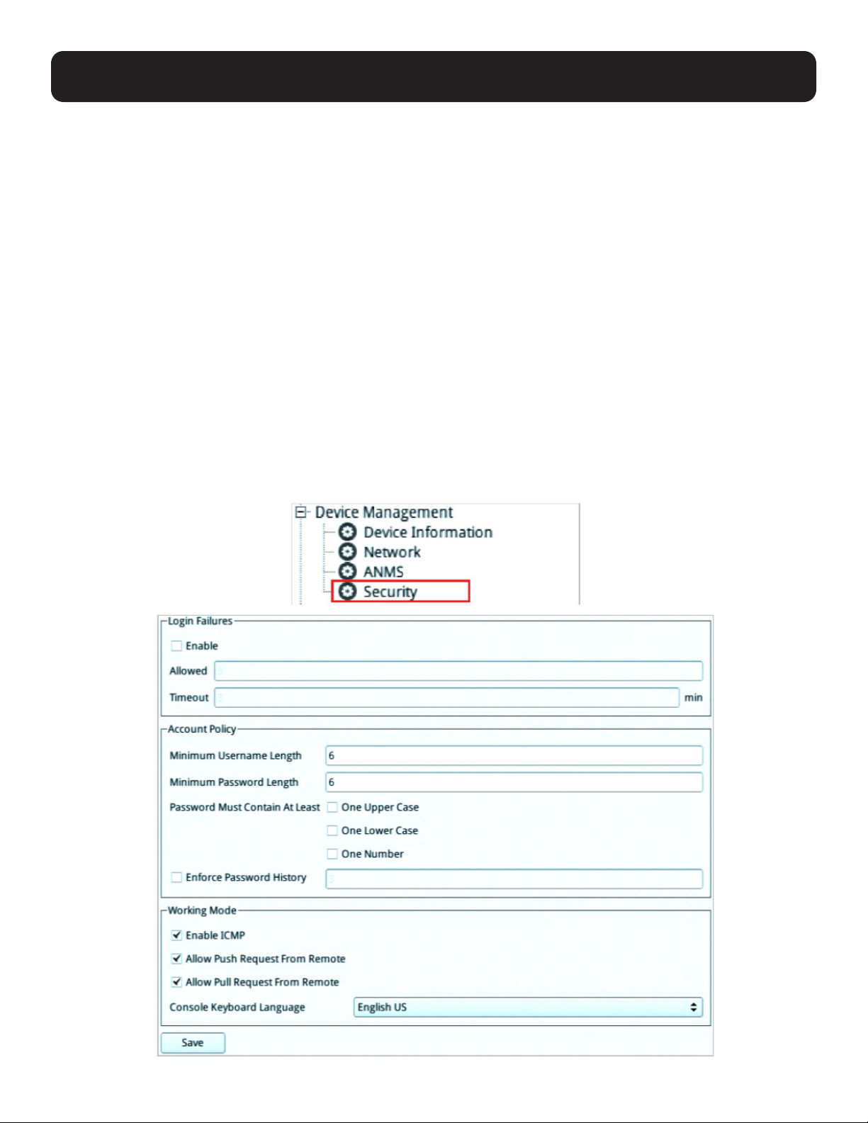
5.2.4 Security
The Security page is divided into 3 main panels, as described in the sections that follow.
Click “Security” under “Device Management” in the left-hand menu to bring up the information page.
36
5. System Configuration
5.2.4.1 Login Failures
For increased security, the Login Failures section allows administrators to set policies governing what happens when a user
fails to log in successfully. To set the Login Failures policy, check the Enable checkbox (the default for Login Failures is
enabled). The meanings of the entries are explained in the following table:
Entry Explanation
Allowed Sets the number of consecutive failed login attempts that are permitted from a remote
computer. The default is 5 attempts.
Timeout Sets the amount of times a remote computer must wait before attempting to log in again after
it has exceeded the number of allowed failures. The default is 3 minutes.
Note: If Login Failures is not enabled, users can attempt to log in an unlimited number of times with no restrictions. For security purposes, it
is recommened to enable this function and the lockout policies.
5.2.4.2 Account Policy
In the Account Policy section, system administrators can set policies governing user names and passwords.
The meanings of the Account Policy entries are explained in the following table:
Entry Explanation
Minimum Username Length
Sets the minimum number of characters required for a user name from 1 to 32. The default is
6.
Minimum Password Name Sets the minimum number of characters required for a password from 0 to 32. A setting of 0
means that no password is required. Users can log in with only a user name. The default is 6.
Password Must Contain at
Least
Checking any of these items requires users to include at least one uppercase letter, one
lowercase letter, or one number in their password.
Note: This policy only affects user accounts created after this policy has been enabled and password
changes to existing user accounts.
Enforce Password History Check this to prevent users from logging in with the same account at the same time.
5.2.4.3 Working Mode
An explanation of the Working Mode items is given in the following table:
Item Explanation
Enable ICMP
Check/uncheck to enable/disable the KVM over IP Console Station to be pinged. The default is
enabled.
Allow Push Request from
Remote
Check/uncheck to allow/disallow another KVM over IP Console Station to push configuration or
FW to your console station.
Allow Pull Request from
Remote
Check/uncheck to allow/disallow another KVM over IP Console Station to pull configuration
from your console station.
Console Keyboard
Language
Click the drop down menu to select the console’s local keyboard language.
5.2.4.4 Finishing Up
After making any Security changes, click “Save” at the bottom of the configuration page.
37
5. System Configuration
5.3 Maintenance
The Maintenance function is used to upgrade firmware, backup and restore configuration and account information, push/pull
configurations, send terminal commands, ping network devices and restore default values.
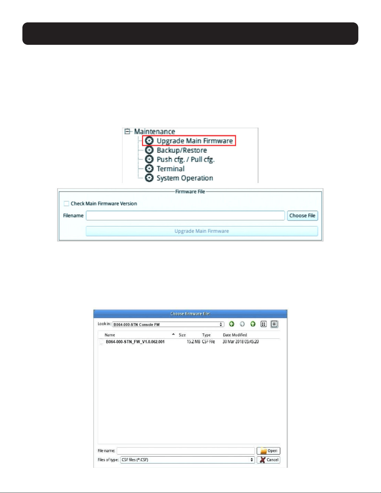
5.3.1 Upgrade Main Firmware
As new versions of the firmware become available, they can be downloaded from tripplite.com/support.
Click “Upgrade Main Firmware” under “Maintenance” in the left-hand menu to bring up the information page.
To upgrade the main firmware:
1. Get the latest firmware by downloading the firmware from tripplite.com/support to a computer.
2. Unzip the .zip file for the .csf file and transfer it to a USB flash drive.
Note: Use FAT file system-formatted USB flash drive(s).
3. Remove the USB flash drive from the computer and insert it into a USB port of the console station.
4. On the console station firmware page, click “Choose File” and a file management window will open:
38
5. Navigate to the directory that the new firmware file is in, click to select the file and click “Open”.
6. Click Upgrade Main Firmware to start the upgrade procedure.
• If you enabled Check Main Firmware Version, the current firmware level is compared with that of the upgrade file. If the
current version is equal to or higher than the upgrade version, a popup message appears to inform you of the situation and
stops the upgrade procedure.
• If you didn’t enable Check Main Firmware Version, the upgrade file is installed without checking its level.
• Upgrade progress information is shown in a Progress bar.
• Once the upgrade completes successfully, the console station will restart.
7. Log in again and check if the firmware version is the newest one.
Note: To recover from a “failed upgrade” situation, refer to Firmware Upgrade Recovery below.
5.3.2 Firmware Upgrade Recovery
Should the console station’s main firmware upgrade procedure fail and the console station becomes unusable, follow the
firmware upgrade recovery procedure below to recover the console station to its original firmware version:
1. Power off the console station by unplugging the power adapter.
2. Press and hold the reset switch using a pointed object.
3. While holding in the reset switch, power up the console station by replugging the power adapter.
This reverts the console station to use the original factory installed firmware. Try upgrading the main firmware again when the
console station is operational.
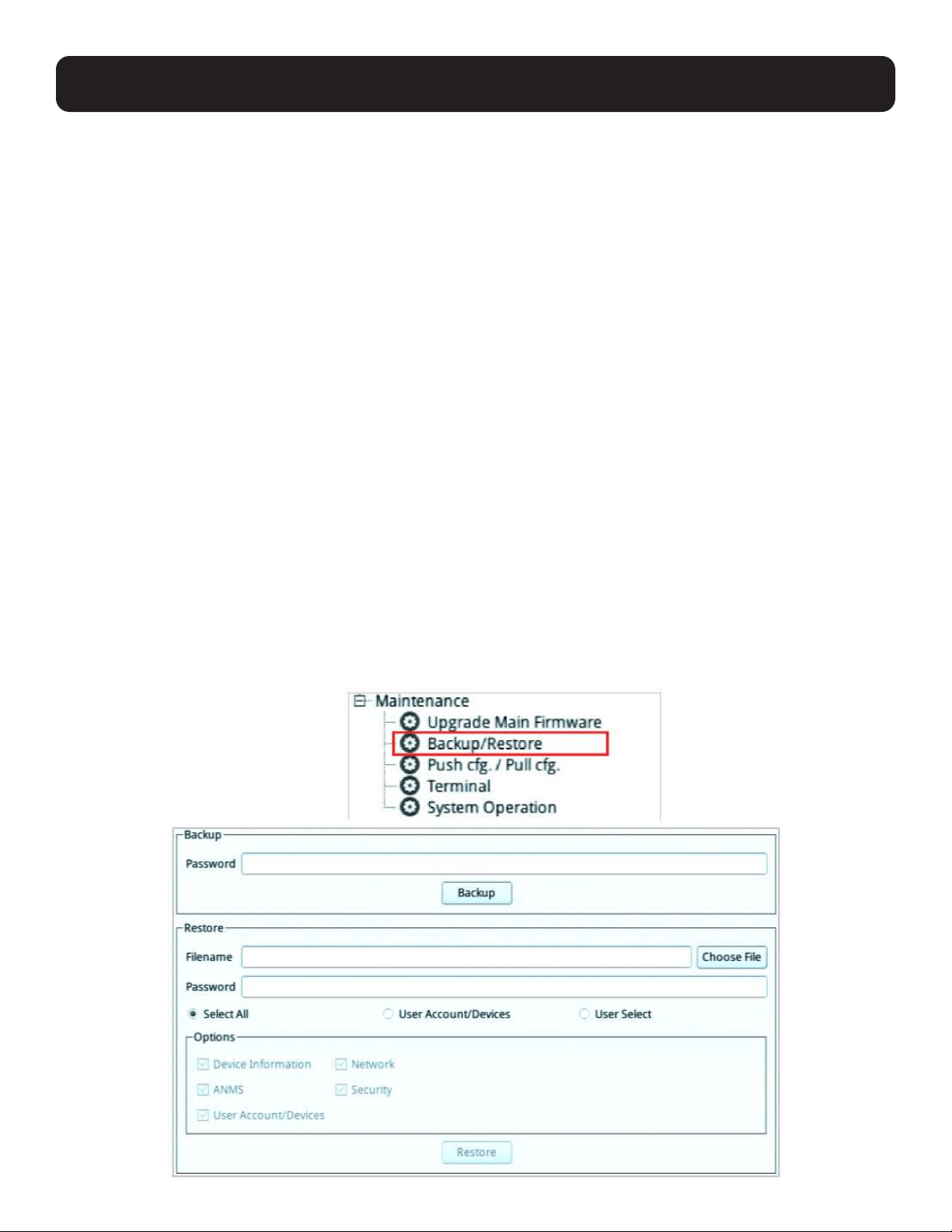
5.3.3 Backup/Restore
Backup/Restore gives you the ability to back up the console station’s configuration and user profile information.
Click “Backup/Restore” under “Maintenance” in the left-hand menu to bring up the information page.
5. System Configuration
39
5. System Configuration
5.3.3.1 Backup
To back up the device’s settings:
Note: A USB flash drive is required to be connected to the console station to store the backup file.
1. (Optional) In the Password field, key in a password for the file.
Notes:
• Setting a password is optional. If you do not set one, the file can be restored without specifying a password.
• If you do set a password, make a note of it, since you will need it to be able to restore the file.
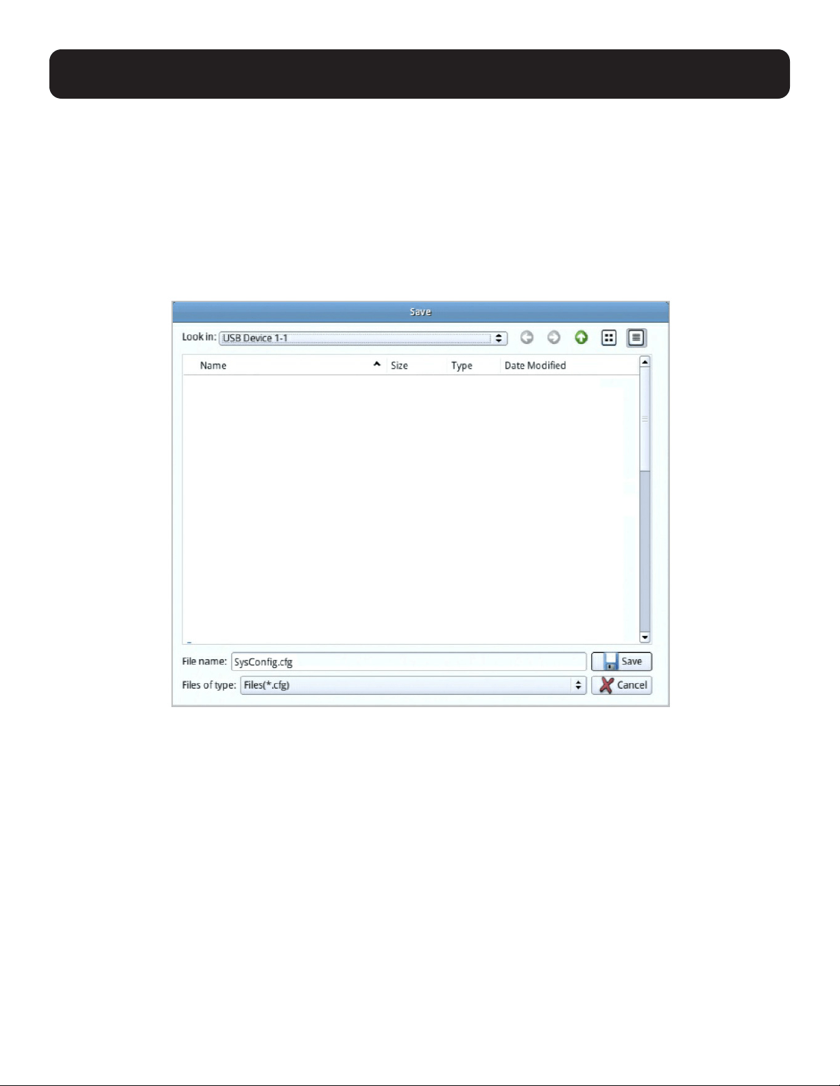
2. Click “Backup”. A file management window will open as shown below:
3. In the File name field, enter a backup file name and click “Save”. The system will display a success message to indicate
successful backup.
40
5. System Configuration
5.3.3.2 Restore
To restore previously saved settings:
Note: A USB flash drive with the previously backed-up file is required to be connected to the console station for backup file retrieval.
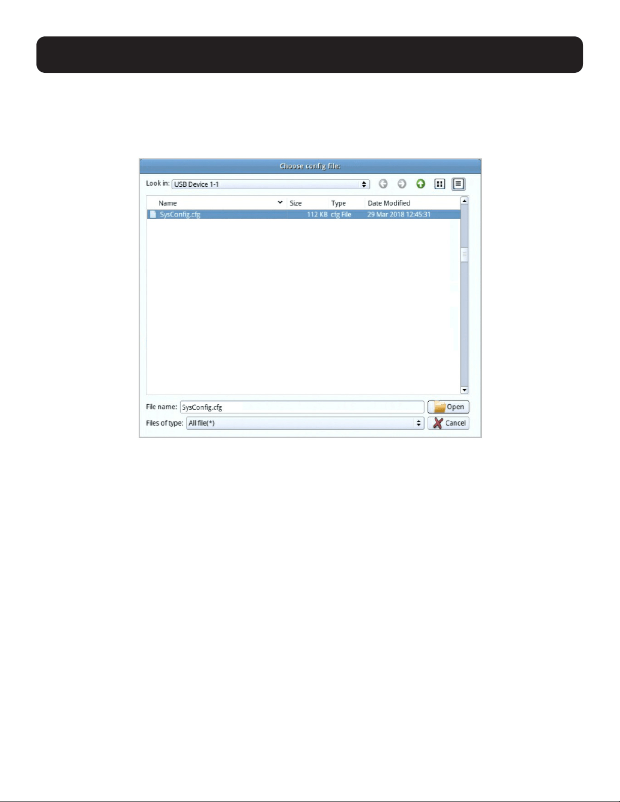
1. Click the “Choose File” button for the file management window:
2. Where applicable, go to the directory with the backup file (.cfg), click to select the file (highlighted as shown above) and
click “Open”.
3. If you set a password when you created the file, key it in the Password field.
4. Select as many of the options that are presented as you wish to restore.
5. Click “Restore”.
The system will display a success message to indicate the restoration was successful.
A “Your system will automatically restart in one minute” message will follow the success message before the system restarts.
41
5. System Configuration
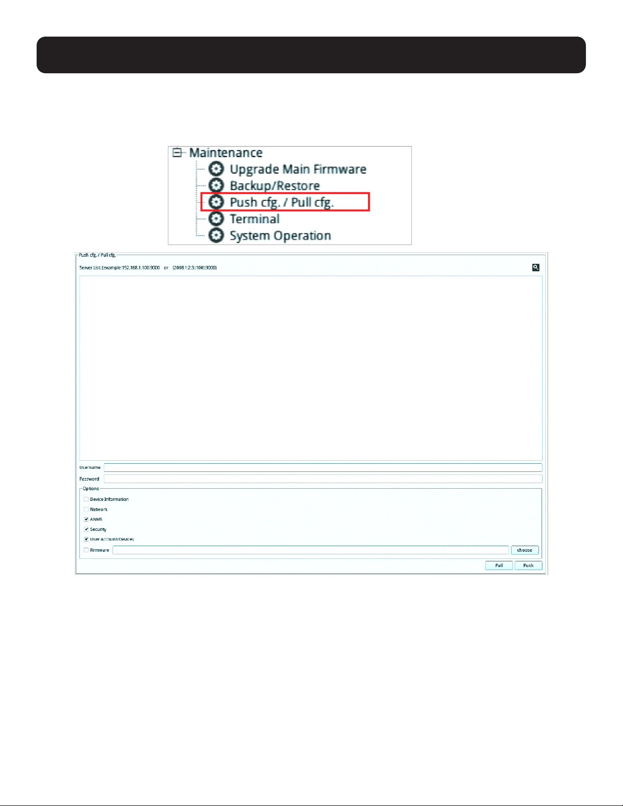
5.3.4 Push/Pull Configuration
Push/Pull Configuration gives you the ability to deploy or retrieve your settings to or from other console stations.
Click “Push cfg./Pull cfg.” under “Maintenance” in the left-hand side menu to bring out the information page.
42
5. System Configuration
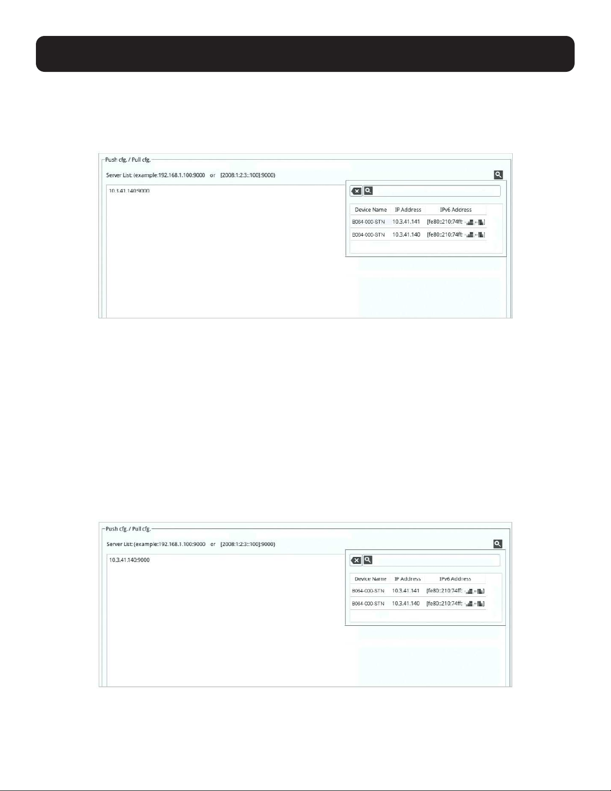
5.3.4.1 Pull Configuration
To pull (retrieve) a configuration to your console station:
1. Enter the device’s IP address or IPv6 Address you wish to retrieve the configuration from. Alternatively, you can hover your
mouse over the magnifying glass to find a list of the devices on the same LAN and click the device’s IP or IPv6 address:
2. Enter the administrative user name and password of the selected device.
3. Select the information you would like to retrieve to your console station by checking the checkbox(es).
Note: Firmware files cannot be retrieved. If you check the Firmware checkbox, the Pull button will not be available.
4. Click “Pull” to retrieve the information.
The console station will restart after successfully retrieving the information.
5.3.4.2 Push Configuration
To push (deploy) a configuration from your console station:
Note: You can deploy the configuration/FW to multiple devices using one procedure (shown below) instead of one procedure for every
device.
1. Enter the device’s IP address(es) or IPv6 address(es) you wish to deploy the configuration to. Alternatively, you can hover
your mouse over the magnifying glass to find a list of the devices on the same LAN and click the device’s IP or IPv6
address:
2. Enter the administrative user name and password of the selected device(s).
3. Select the information you would like to deploy from your console station by checking the checkbox(es).
Note: If you checked the Firmware checkbox, please remember to click the Choose button to select a firmware from a USB flash drive.
43
5. System Configuration
4. Click “Push” to deploy the information.
The console station(s) will restart after successfully receiving the deployment information.
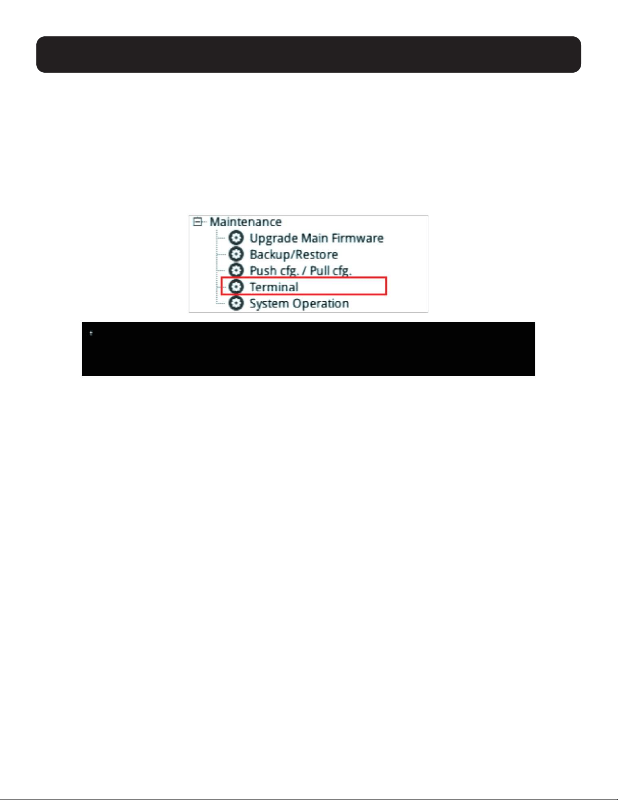
5.3.5 Terminal
Terminal provides a command line to execute options using a terminal interface. Type a command in the window and hit
[Enter] to execute it.
Click “Terminal” under “Maintenance” in the left-hand menu to bring up the terminal page.
Note: Expand the submenu by clicking the + symbol if “Terminal” is not shown.
Available commands include:
• GET => Gets current configuration.
• HELP => Provides Help information for commands.
• CLEAR => Clears the screen.
• PING => Displays ping host information.
• SETLDAPMEMBER => Sets new value for LDAP member.
• SETLDAPMEMBEROF => Sets new value for LDAP member of.
• SETPROMPT => Sets prompt string.
• TRACERT => Displays trace route information.
• DEVICEHISTORY => Clear/Enable/Disable device list history
• SELFDIAGNOSTIC => Self Diagnostic
44
5. System Configuration
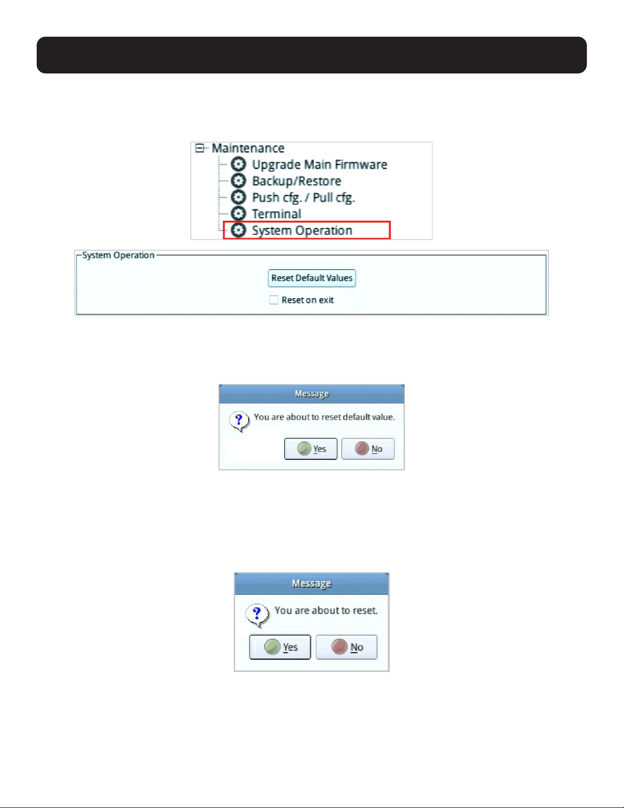
5.3.6 System Operation
The System Operation page lets you restore certain configuration changes that were made to the KVM over IP Console Station
back to their original factory default values.
5.3.6.1 Reset Default Values
Clicking this button undoes all Customization page changes that have been made to the KVM over IP Console Station and
returns the parameters to the original factory default settings. The system will ask for confirmation:
Click “Yes” to proceed. The system will restart after the reset.
Click “No” to cancel the operation.
5.3.6.2 Reset on Exit
If you checked the checkbox, the system will ask if you would like to reset the KVM over IP Console Station (and implement all
the new settings) upon exiting the System Configuration page.
Click “Yes” to go ahead with the reset (the system will also reboot).
Click “No” if you do not want the system to be reset.
If you change the console station’s IP address (see section 5.2.2 Network), the checkbox is automatically checked and the
console station will reset when you exit the page.
45
5. System Configuration
If you clear the check mark before exiting the page, the changes to the IP settings will be ignored and the original IP address
settings will remain in effect.
Note: Even though the changed IP settings are ignored, they still remain in the network settings fields. That means that the next time you
open this page the Reset on Exit checkbox will automatically be enabled, and when the console station resets, the new IP settings that you
thought you discarded will become the ones used by the console station. To avoid this problem, go back to the network settings page and
ensure the IP settings that appear in the fields are the ones you want to use.
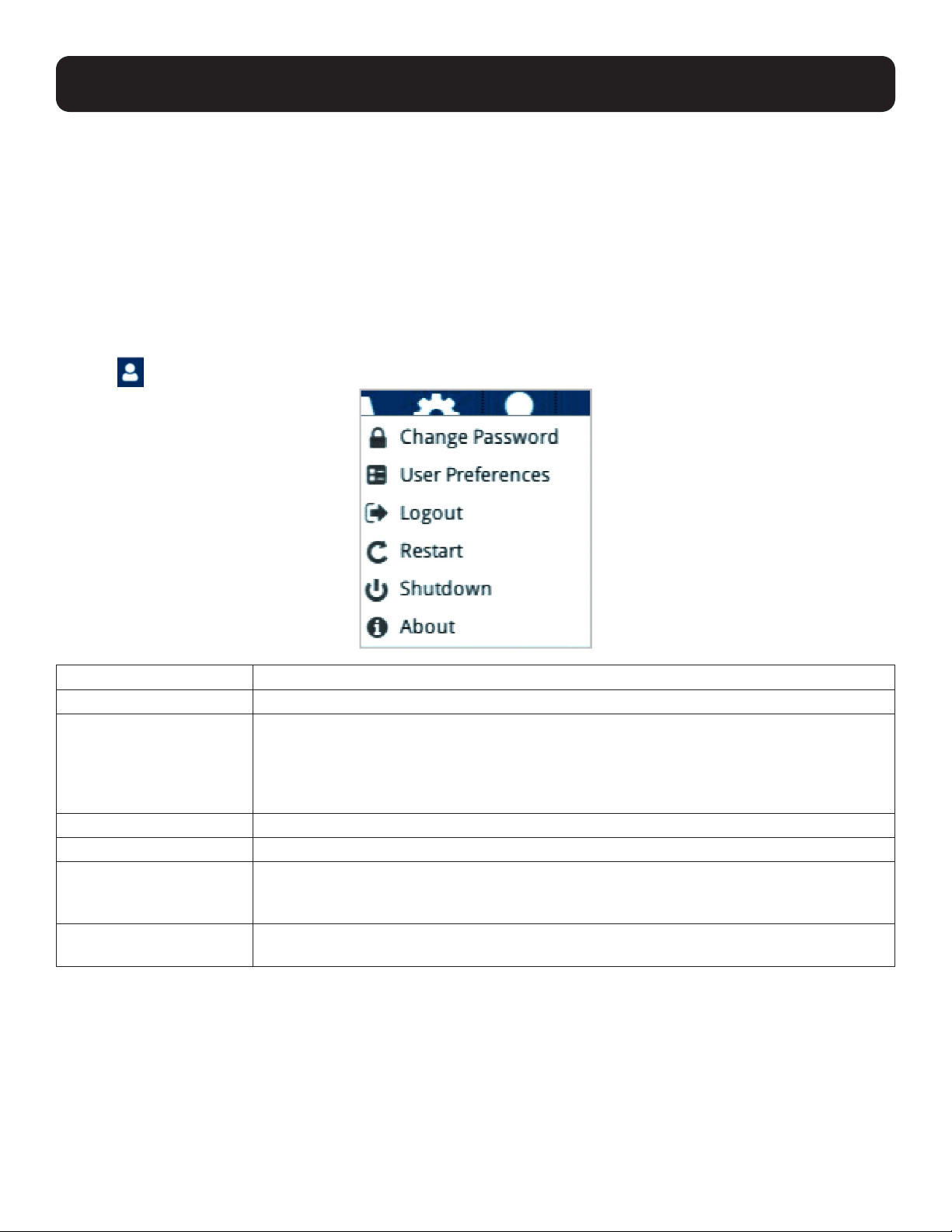
5.4 Quick User Configuration
The user icon allows quick access to password change, configure preferences, logout, restart the system, shut down the
system, or display quick information about the console station.
Click the
User icon for its menu:
Option Description
Change Password
Click this option to change the password of the current user.
User Preferences Select the preferred language from the scroll menu. Language change will be shown
immediately.
Logout Timeout is the idle time period (no actions) where the system automatically logs you
out. Set a logout timeout time in minutes. Enter 0 if you do not want the system to log you out
from idling.
Logout Click this option to log out of the system.
Restart Click this option to restart the system.
Shutdown Click this option to safely shut down the system.
This is the recommended way to shut down the system. Disconnect the power adapter after
the system displays a safe-to-shutdown message.
About Click this option to display the KVM over IP Console Station’s device name, firmware version,
IP address and IPv6 address.
46
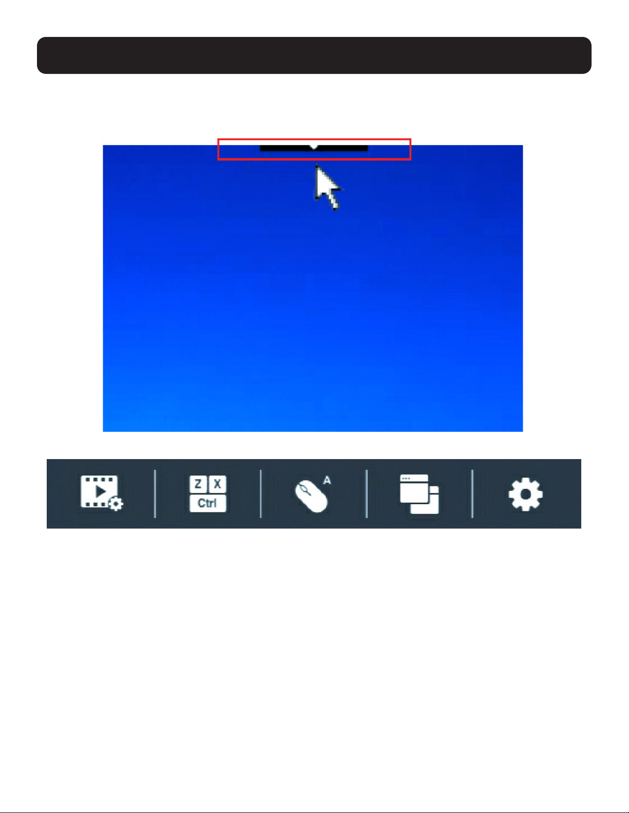
6. Toolbar Interface
The KVM over IP Console Station’s interface provides a toolbar to help you with the remote control operations on the captured
port. The toolbar is usually hidden.
To bring up the toolbar, locate a down arrow symbol as shown:
Hover your mouse over the down arrow symbol to bring up the toolbar.
47
6. Toolbar Interface
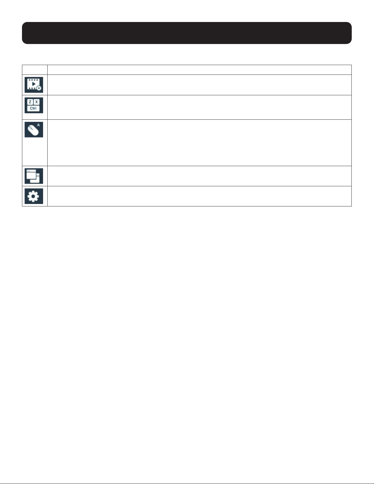
The meanings of the toolbar icons are explained in the following table:
Option Description
Video icon
Brings up the video settings. See section 6.2 Video Settings for more details.
Macros icon
Provides access to three functions found in the Macros dialog box: Hotkeys, User Macros and System macros. See
section 6.3 Macros for more details.
Mouse Sync Mode icon
Provides automatic locked-in syncing of the remote and local mouse pointers – eliminating the need to constantly
resync the two movements.
Click the icon to toggle between Auto Mouse Sync Mode (mouse icon with an A) and Manual Mouse Sync Mode
(mouse icon with an M).
See section 6.4.3 Mouse Sync Mode for more details.
Connect icon
Click for a list of available ports. Click to select the port you wish to connect to.
Configuration icon
Click for further configurations. See section 6.4 Further Configuration.
6.1 Exit Remote Location
There are two ways to exit from the remote control operations on the captured port.
1. Click Back
On the toolbar interface, click the “Configuration icon” for more operation options. Click “Back” to exit remote location.
2. Use Macros
By default, pressing the “Exit Remote Location” hot keys (F2, F3, F4) will also exit remote location.
Note: Use the updated hot keys should there be a change to this function’s hot key.
48
6. Toolbar Interface
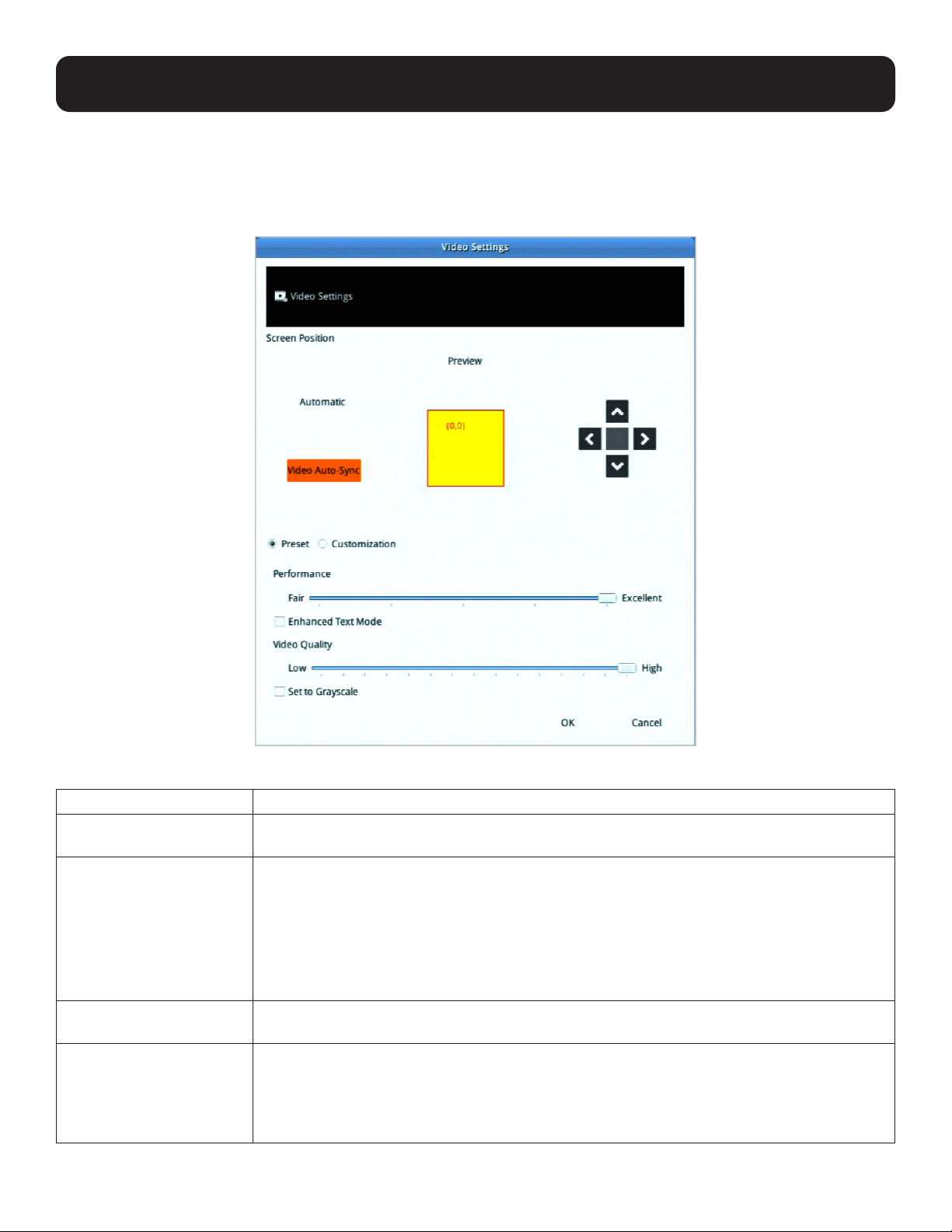
6.2 Video Settings
Click the Video icon on the toolbar to bring up the Video Settings dialog box. The options in the basic dialog box allow you to
adjust the Screen Position, set Auto Sync, adjust Performance bar setting, Enhanced Text Mode, adjust Video Quality bar, and
Set to Grayscale.
The video adjustment options are described in the following table:
Option Description/Operation
Screen Position
Adjust the horizontal and vertical position of the remote server window by clicking the Arrow
buttons.
Video Auto-Sync Click Video Auto Sync to have the vertical and horizontal offset values of the remote screen
detected and automatically synchronized with the local screen.
Notes:
1. If the local and console station mouse pointers are out of sync, in most cases, performing this
function will bring them back into sync.
2. This function works best with a bright screen.
3. If you are not satisfied with the results, use the Screen Position arrows (on the right) to position the
remote display manually.
Preset/ Customization Using the Preset and Custom buttons allows you to set and save custom video settings, and
revert back to default video settings.
Performance Use the slide bar to select the type of Internet connection the console station uses. Dragging
the performance bar will also automatically adjust the Video Quality settings to optimize the
quality of the video display.
Because network conditions vary, if none of the preset choices seem to work well, use the
Video Quality slide bar to adjust the settings to suit your conditions.
49
6. Toolbar Interface
Option Description/Operation
Enhanced Text Mode Check to enhance color and video quality, especially for text.
Video Quality Drag the slider bar to adjust the overall Video Quality. The larger the value, the clearer the
picture and the more video data goes through the network. Depending on the network
bandwidth, a high value may adversely affect response time.
Set to Grayscale Check to set video display to grayscale.
6.3 Macros
The Macros icon provides access to three functions found in the Macros dialog box: Hotkeys, User Macros and System
Macros. Each of these functions is described in the following sections.
50
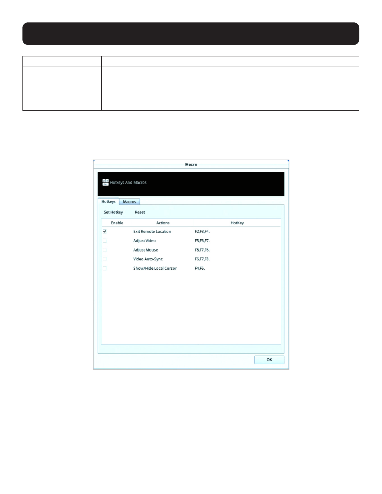
6.3.1 Hotkeys
Various actions related to manipulating the remote server can be accomplished with hotkeys. The Hotkey Setup utility
(accessed by clicking this icon) lets you configure which hotkeys perform the actions.
Each action in the Actions column corresponds to the hotkeys in the HotKey column on the same row. Check the checkbox in
the Enable column on the same row to enable its hotkey.
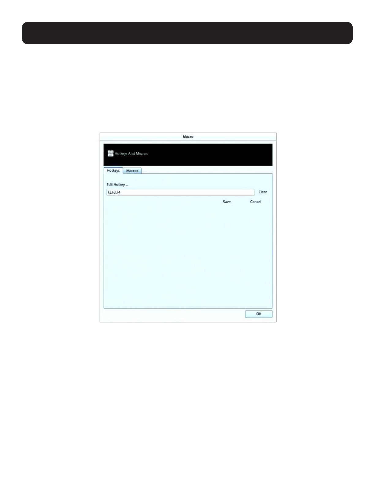
To change the hotkey for an action:
1. If you are not in the “Hotkeys” tab, click to select to go into the Hotkeys page.
2. Highlight the Action and click Set Hotkey for the window dialog below:
3. Press your selected Function keys (one at a time). The key names will appear in the Hotkeys field as you press them.
• You can use the same function keys for more than one action, as long as the key sequence is not the same.
• To cancel setting a hotkey value, click “Cancel”; to clear an action’s Hotkeys field, click “Clear”.
4. When you have finished keying in your sequence, click “Save”.
6. Toolbar Interface
51
6. Toolbar Interface
To reset all the hotkeys to their default values, click “Reset”.
An explanation of the Hotkey actions is given in the following table:
Action Explanation
Exit Remote Location
Breaks the connection to the KVM over IP Console Station and returns you to console station
operation. This is equivalent to clicking the Back option under the Configuration icon of the
toolbar. The default keys are F2, F3, F4.
Adjust Video Brings up the Video Settings dialog box. This is equivalent to clicking the Video Settings icon
on the console station toolbar. The default keys are F5, F6, F7.
Adjust Mouse Synchronizes the local and remote mouse movements. The default keys are F8,F7,F6.
Video Auto-Sync This combination performs an auto-sync operation. It is equivalent to clicking the Video Auto
Sync button in the Video Settings dialog box. The default keys are F6,F7,F8.
Show / Hide Local Cursor Toggles off and on: hides local cursor and locks the mouse pointer and keyboard use within the
Windows/Java Client AP window, plus hides the control panel. This is equivalent to selecting the
Single pointer type from the Mouse Pointer option under the Configuration icon of the toolbar.
The default keys are F4,F5.
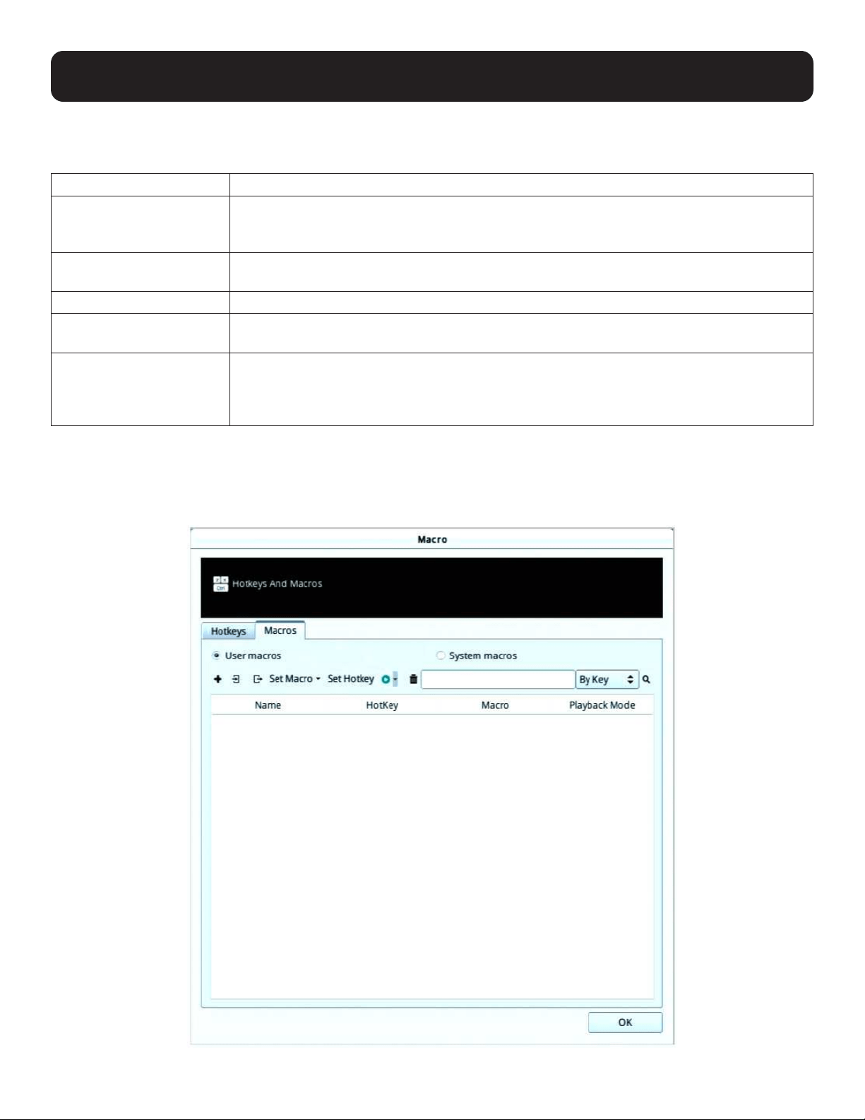
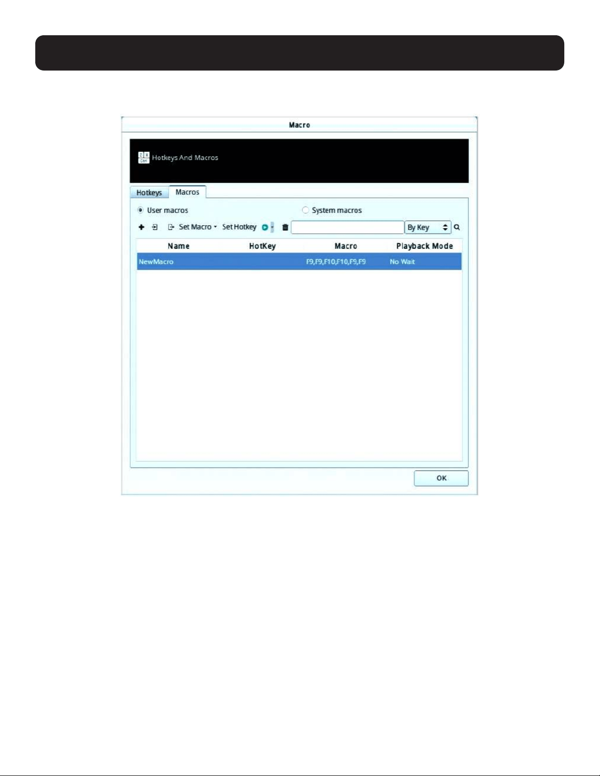
6.3.2 User Macros
User Macros are created to perform specific actions on the remote server. To create a macro, do the following:
1. If you are not in the “Macros” tab, click to select the tab to go into the Macros page.
52
6. Toolbar Interface
2. Select User Macros and click the + symbol.
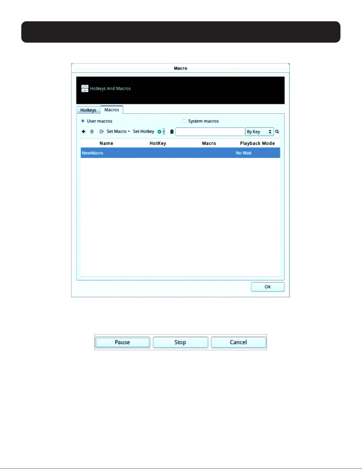
3. In the dialog box, you can choose to replace the “New Macro” text with a name of your choice for the macro.
4. Click “Set Macro” followed by “Record”.
The dialog box disappears as a small panel appears at the top left of the screen:
5. Press the keys for the macro.
• To pause macro recording, click “Pause”. To resume, click “Pause”again.
• Clicking “Cancel”cancels all keystrokes.
Notes:
1. Case is not considered – typing A or a has the same effect.
2. Only the default keyboard characters may be used. Alternate characters cannot be used. For example, if the keyboard is Traditional
Chinese and default character is A the alternate Chinese character obtained via keyboard switching is not recorded.
53
6. Toolbar Interface
6. When finished, click “Stop”. You will return to the Macros dialog box with your macro key presses displayed in the Macro
column:
54
6. Toolbar Interface
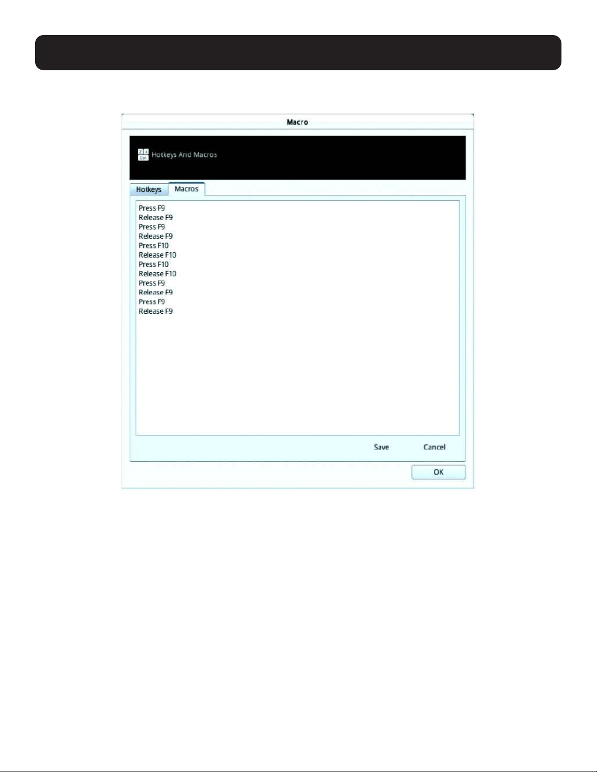
7. If you want to change any of the keystrokes, select the macro, click “Set Macro” followed by “Edit”. This brings up a dialog
box. You can change the content of your keystrokes, change their order, etc.
8. Click “Save” to save the changes, or click “Cancel” to cancel the changes. Both options will return you to the Macros dialog
box.
9. Repeat the procedure for any other macros you wish to create.
After creating your macros, you can run them in either of two ways:
1. By using the hotkey (if one was assigned).
2. By playing it in this dialog box.
55
6. Toolbar Interface
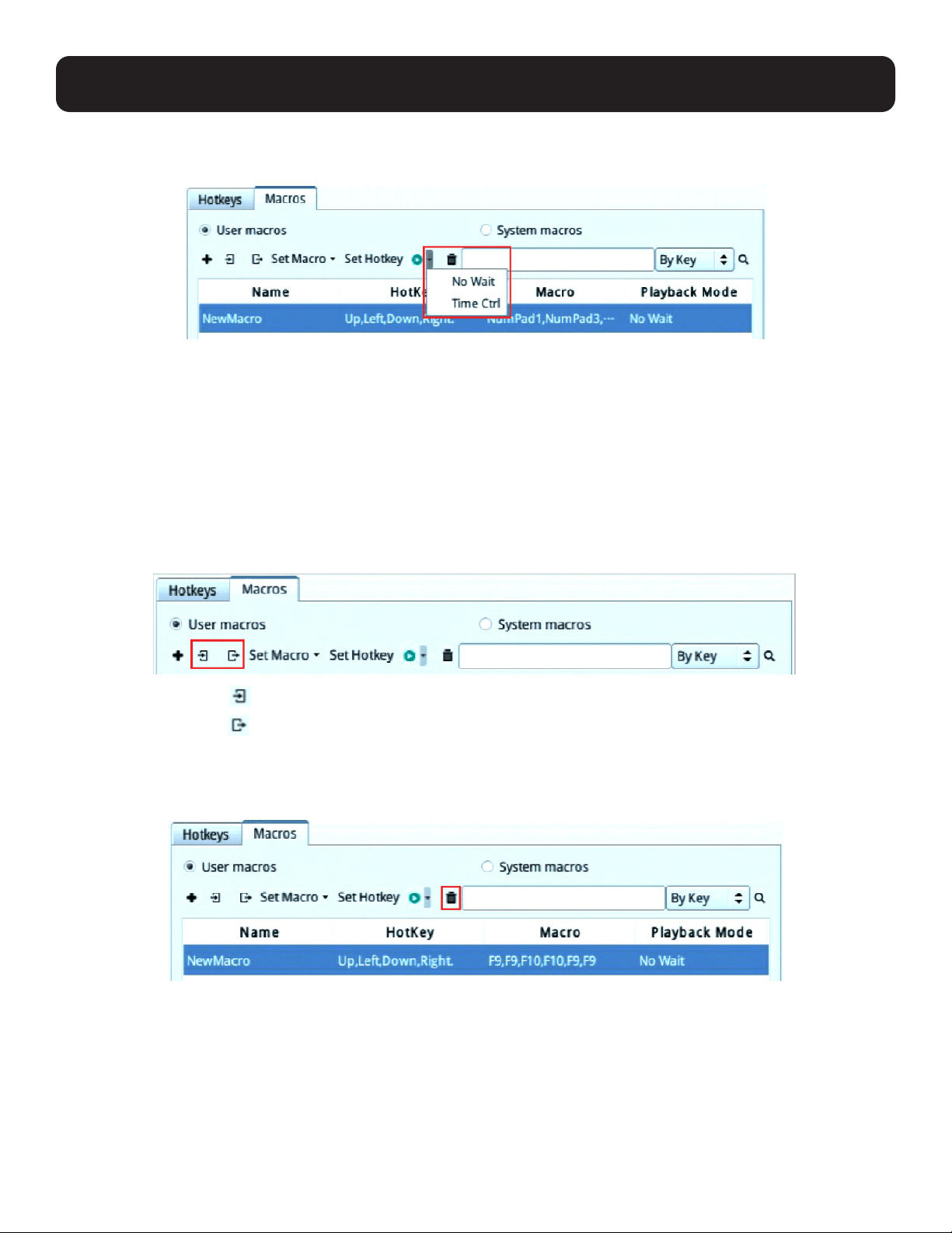
If you run the macro from this dialog box, you have the option of specifying how the macro runs. Click the down arrow symbol
to select your option.
• No Wait: The macro runs the key presses one after another with no time delay between them.
• Time Ctrl (time control): The macro waits for the amount of time between key presses that you took when you created it.
• If you click the Play symbol without selecting an option, the macro runs with the default choice (No Wait or Time Ctrl), which
is shown in the Playback Mode column.
You can change the default choice by clicking on the current choice (No Wait in the screenshot above), and selecting the
alternate choice.
6.3.3 Import / Export Macros
The import / export function allows you to import or export macros from or to a USB flash drive.
• Click the import symbol to search through the USB flash drive to import the macros.
• Click the export symbol and enter a name to save the macros to the USB flash drive.
6.3.4 Delete Macros
To delete a macro, click to select the macro and click the trash can symbol.
56
6. Toolbar Interface
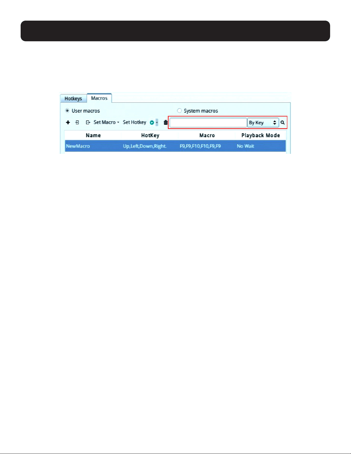
6.3.5 Search Macros
The search function (at the top right-hand side of the dialog box) lets you filter the list of macros that appear in the list. Click
the drop-down arrow (next to the magnifying glass icon) to choose search by name or by key; enter a string in the search field
for the search; then click the “Search” symbol (magnifying glass symbol). All instances that match your search string appear in
the list.
6.3.6 System Macros
System Macros are used to create exit macros for closing a session. For example, as an added measure of security, you could
create a macro that sends the Winkey-L combination which would cause the remote server’s login page to come up the next
time the device was accessed.
Ways to create, delete or search for macros are the same as User Macros (refer to section 6.3.2). System macros cannot be
imported or exported.
For more information on system macros for your KVM over IP switches, refer to their user manuals.
57
6. Toolbar Interface
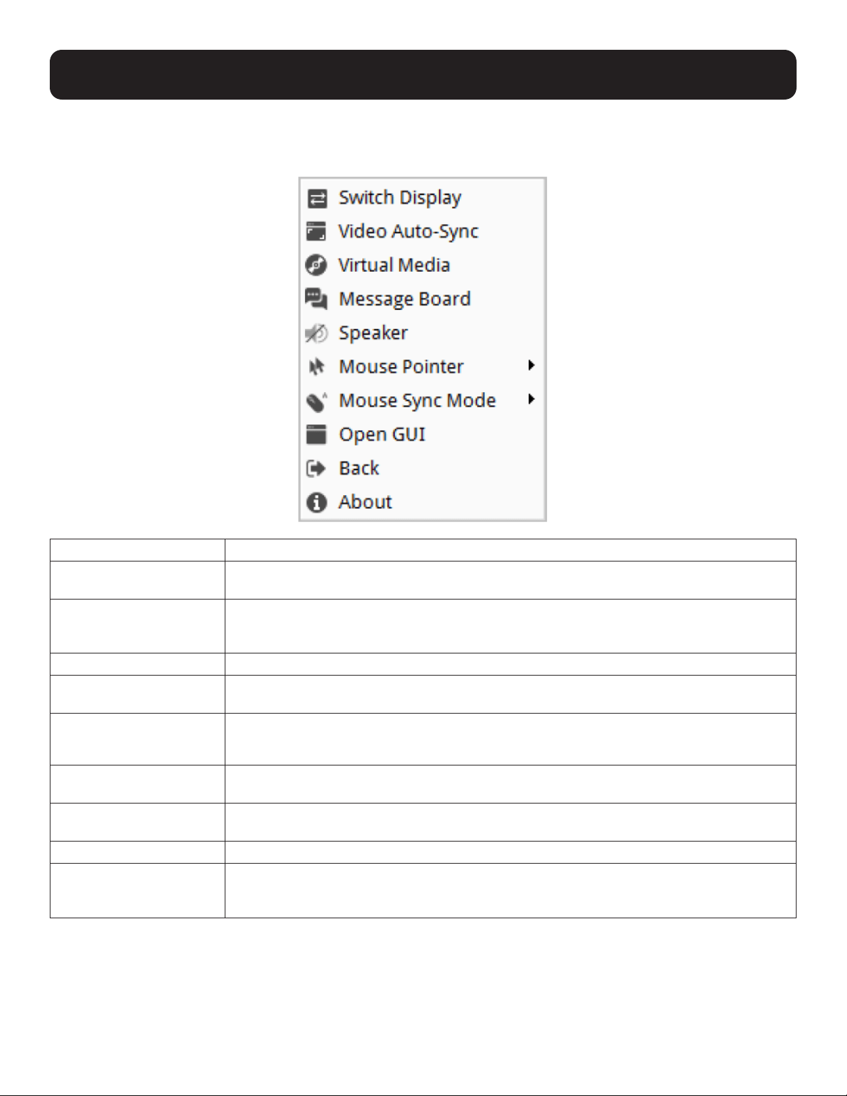
6.4 Further Configuration
More configuration options are available when clicking the configuration icon:
Options Description
Video Auto-Sync
Click to perform a video and mouse auto-sync operation. It is the same as clicking the Auto Sync
button in the Video Options dialog box (see section 6.2 Video Settings).
Virtual Media
Click to bring up the Virtual Media dialog box. See section 6.4.1 Virtual Media for specific
details.
Note: This icon displays in gray when the function is disabled or not available.
Message Board
Click to bring up the Message Board (see section 6.4.2 Message Board).
Speaker Click to toggle sound from the remote server to be heard on the client computer’s speakers on
or off. The option is grayed out when the speaker is toggled Off.
Mouse Pointer Hover your mouse over the option and click to select the mouse pointer type.
Note: In the main GUI page, only Dual and Crosshairs are available. In a port page, three pointers are
available.
Mouse Sync Mode Hover your mouse over the option and click to select the mouse sync mode.
See section 6.4.3 Mouse Sync Mode.
Open GUI Click to open the GUI of the connected KVM over IP switch. Refer to the owner’s manual of the
connected KVM over IP switch for more details.
Back Click to return to the page on the KVM over IP Console Station that brought you here.
About Click to get information about this connection.
The information includes Device Name, IP Address, Current Port, Video Mode and Channel /
User Numbers.
58
6. Toolbar Interface
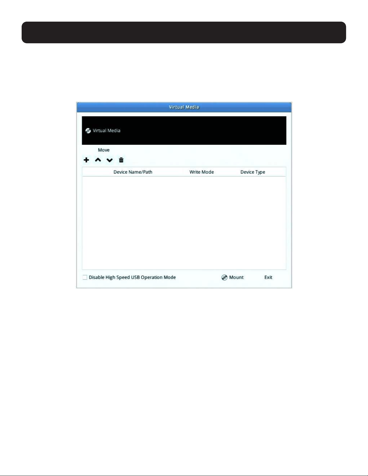
6.4.1 Virtual Media
The Virtual Media feature allows a removable USB drive on a user’s system to appear and act as if it were installed on the
remote server.
To mount a virtual media device:
1. Click the Virtual Media icon to bring up the Virtual Media dialog box:
59
6. Toolbar Interface
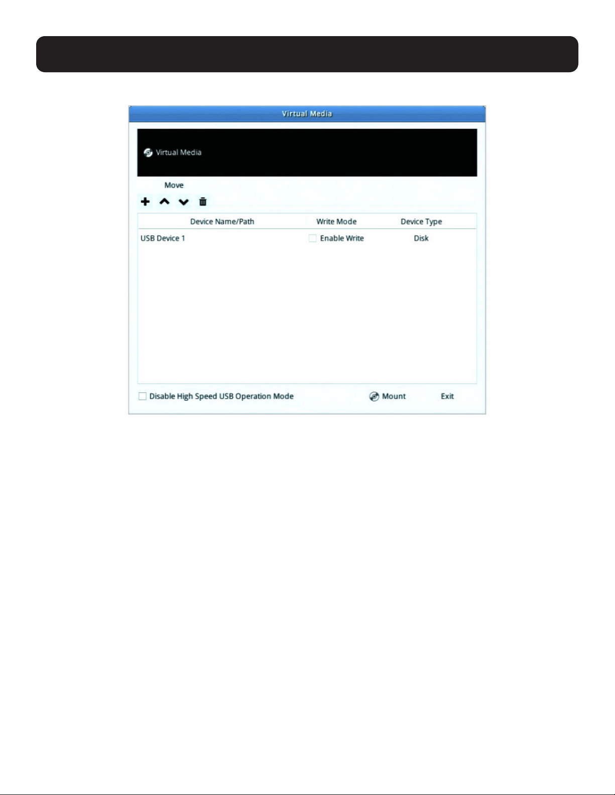
2. Click the + symbol and select the media source.
3. If your device only supports full speed USB, check the Disable High Speed USB Operation Mode checkbox.
4. To add additional media sources, click the + symbol and select the source as many times as you require. Up to two virtual
media choices can be mounted. The top three in the list are the ones that are selected. Virtual Media and Smart Card
readers can be mounted at the same time. To rearrange the selection order, highlight the device you want to move, then
click the Up or Down Arrow button to promote or demote it in the list.
5. Read refers to the redirected device being able to send data to the remote server; Write refers to the redirected device
being able to have data from the remote server written to it. For the redirected device to be writable as well as readable,
click to put a check in the Enable Write checkbox.
Note: If a redirected device cannot be written to, it appears in gray.
6. To remove an entry from the list, select it and click the trash can icon.
7. After you have made your media source selections, click “Mount”. The dialog box closes. The virtual media devices that you
have selected are redirected to the remote server, where they show up as drives on the remote server’s file system.
Once mounted, you can treat the virtual media as if they really exist on the remote server – drag and drop files to/from them,
open files on the remote server for editing and save them to the redirected media, etc.
8. To end the redirection, bring up the Control Panel and click on the Virtual Media icon. All mounted devices are automatically
unmounted.
60
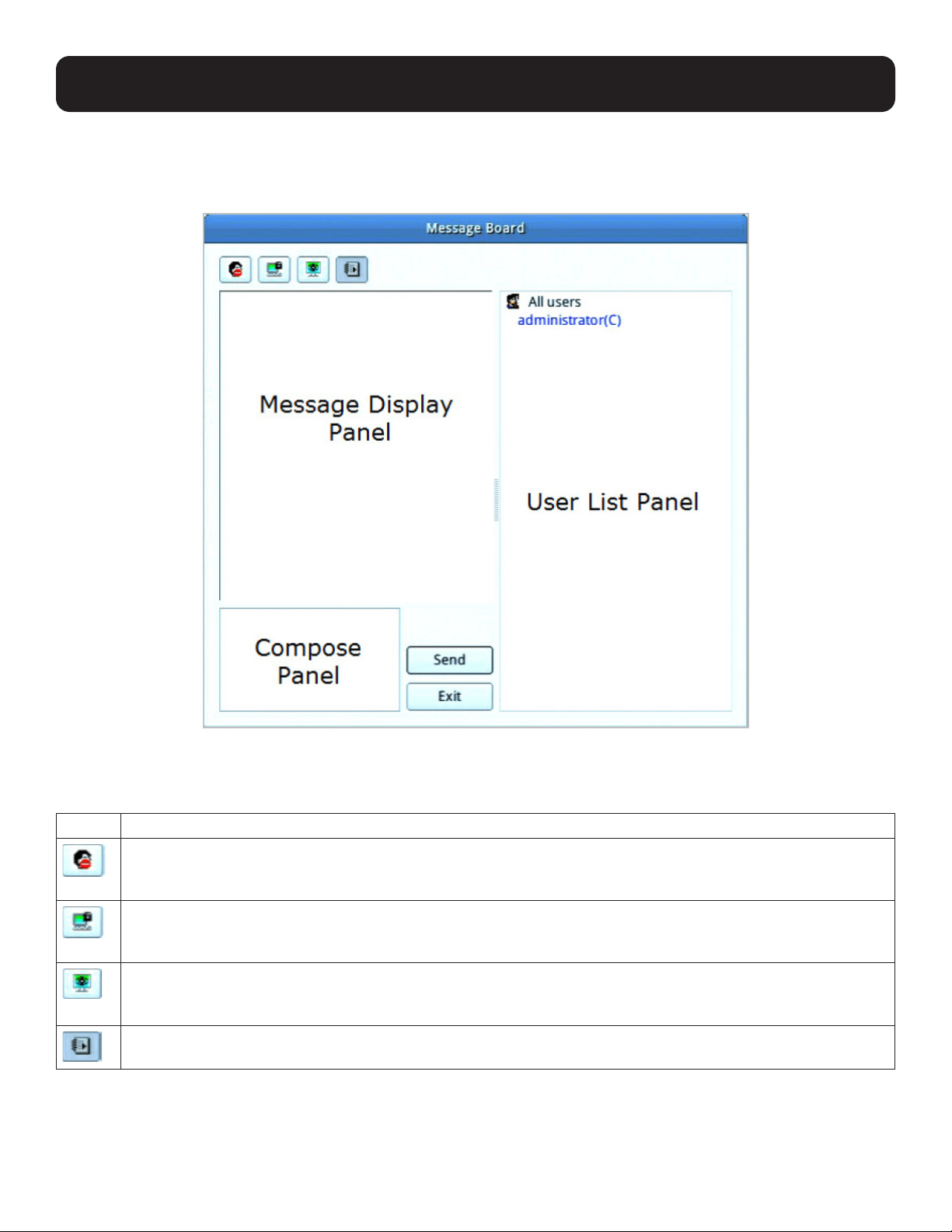
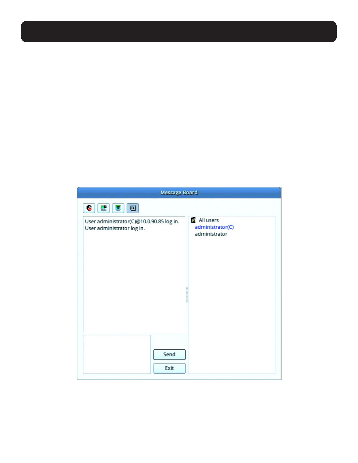
6.4.2 Message Board
The KVM over IP Console Station supports multiple user logins, which may cause access conflicts. To alleviate the problem, a
message board has been provided to allow users to communicate with each other.
6.4.2.1 Buttons
The buttons in the dialogue box toggles actions and are described in the following table:
Button Action
Enable/Disable Chat. When disabled, messages posted to the board are not displayed. The button is shadowed
when Chat is disabled. The icon displays next to the user’s name in the User List panel when the user has disabled
Chat.
Occupy/Release Keyboard/Video/Mouse. When you Occupy the KVM, other users cannot see the video and
cannot input keyboard or mouse data. The button is shadowed when the KVM is occupied. The icon displays next
to the user’s name in the User List panel when the user has occupied the KVM.
Occupy/Release Keyboard/Mouse. When you Occupy the KM, other users can see the video but cannot input
keyboard or mouse data. The button is shadowed when the KM is occupied. The icon displays next to the user’s
name in the User List panel when the user has occupied the KM.
Show/Hide User List. When you Hide the User List, the User List panel closes. The button is shadowed when the
User List is open.
6. Toolbar Interface
61
6. Toolbar Interface
6.4.2.2 Message Display Panel
Messages that users post to the board - as well as system messages - display in this panel. If you disable Chat, however,
messages that get posted to the board will not appear.
6.4.2.3 Compose Panel
Key in the messages that you want to post to the board in this panel. Click “Send” to post the message to the board.
6.4.2.4 User List Panel
The names of all the logged in users are listed in this panel.
• Your name appears in blue; other users’ names appear in black.
• By default, messages are posted to all users. To post a message to one individual user, select the user’s name before
sending your message.
• If a user’s name is selected and you want to post a message to all users, select All Users before sending your message.
• If a user has disabled Chat, the disable chat icon will be displayed on the left of user’s name.
• If a user has occupied the KVM or the KM, the corresponding icon will be displayed to the left of the user’s name.
62
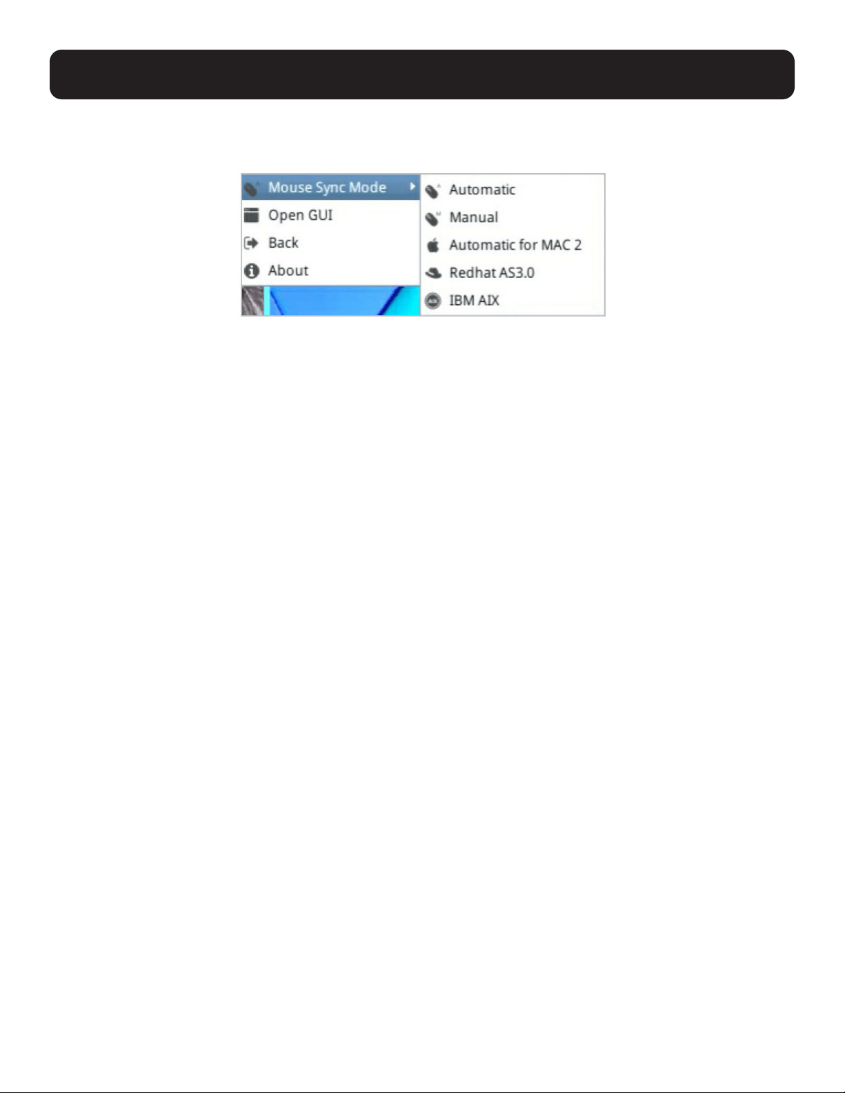
6.4.3 Mouse Sync Mode
Synchronization of the local and remote mouse pointers is accomplished either automatically or manually.
6.4.3.1 Automatic Mouse Synchronization
This provides automatic locked-in syncing of the remote and local mouse pointers – eliminating the need to constantly resync
the two movements.
6.4.3.2 Manual Mouse Synchronization
If the local mouse pointer goes out of sync with the remote system’s mouse pointer there are a number of methods to bring
them back into sync:
1. Perform an Auto Sync with the Video Adjustment function (see section 6.2 Video Settings for details).
2. Invoke the Adjust Mouse function with the Adjust Mouse hotkeys (see section 6.3.1 Hotkeys for details).
3. Set the mouse speed and acceleration for each problematic server attached to the switch. See the user manual of the
corresponding KVM over IP switch for instructions.
6.4.3.3 Mac and Linux Considerations
• For Mac OS versions 10.4.11 and higher, there is a second Sync setting to choose from. If the default Mouse Sync result is
not satisfactory, try the “Mac 2” setting. To select Mac 2, click the Further Configuration icon, hover your mouse over Mouse
Sync Mode → Automatic for Mac 2.
• Linux does not support Sync Mode, but there is a setting on the Mouse Sync Mode menu for Redhat AS3.0 systems. If
you are using a USB Adapter Cable with an AS3.0 system and the default mouse synchronization is not satisfactory, try the
Redhat AS3.0 setting. In either case, you must perform the manual mouse synchronization procedures described above.
6. Toolbar Interface

63
7. Specifications
Model B064-000-STN
Video
HDMI (Female)
RS-232 DB-9 (Male)
Audio (x2) 3.5 mm (Female)
LAN RJ45 (Female)
Keyboard/Mouse (x2) USB 2.0 Type-A (Female)
USB Hub Ports (x2) USB 2.0 Type-A (Female)
Cascade Port RJ45 (Female)
LEDs Power (Blue)
Max Supported Video Resolution 1920 x 1200 @ 60 Hz
Operating Temperature 32°F to 104°F (0°C to 40°C)
Storage Temperature -4°F to 140°F (-20°C to 60°C)
Relative Humidity 0% to 80% RH, Non-Condensing
Dimensions (H x W x D) 6.86 x 5.88 x 1.13 in. (174.2 x 155.7 x 28.8 mm)
Weight 1.65 lb. (0.75 kg)

64
8. Warranty and Product Registration
3-YEAR LIMITED WARRANTY
Tripp Lite warrants its products to be free from defects in materials and workmanship for a period of three (3) years from the date of initial purchase.
Tripp Lite’s obligation under this warranty is limited to repairing or replacing (at its sole option) any such defective products. To obtain service under this
warranty, you must obtain a Returned Material Authorization (RMA) number from Tripp Lite or an authorized Tripp Lite service center. Products must be
returned to Tripp Lite or an authorized Tripp Lite service center with transportation charges prepaid and must be accompanied by a brief description of the
problem encountered and proof of date and place of purchase. This warranty does not apply to equipment which has been damaged by accident, negligence
or misapplication or has been altered or modified in any way.
EXCEPT AS PROVIDED HEREIN, Tripp Lite MAKES NO WARRANTIES, EXPRESS OR IMPLIED, INCLUDING WARRANTIES OF MERCHANTABILITY AND FITNESS
FOR A PARTICULAR PURPOSE. Some states do not permit limitation or exclusion of implied warranties; therefore, the aforesaid limitation(s) or exclusion(s)
may not apply to the purchaser.
EXCEPT AS PROVIDED ABOVE, IN NO EVENT WILL Tripp Lite BE LIABLE FOR DIRECT, INDIRECT, SPECIAL, INCIDENTAL OR CONSEQUENTIAL DAMAGES ARISING
OUT OF THE USE OF THIS PRODUCT, EVEN IF ADVISED OF THE POSSIBILITY OF SUCH DAMAGE. Specifically, Tripp Lite is not liable for any costs, such as lost
profits or revenue, loss of equipment, loss of use of equipment, loss of software, loss of data, costs of substitutes, claims by third parties, or otherwise.
PRODUCT REGISTRATION
Visit www.tripplite.com/warranty today to register your new Tripp Lite product. You’ll be automatically entered into a drawing for a chance to win a FREE
Tripp Lite product!
** No purchase necessary. Void where prohibited. Some restrictions apply. See website for details.
FCC Notice, Class A
This device complies with part 15 of the FCC Rules. Operation is subject to the following two conditions: (1) This device may not cause harmful interference,
and (2) this device must accept any interference received, including interference that may cause undesired operation.
Note: This equipment has been tested and found to comply with the limits for a Class A digital device, pursuant to part 15 of the FCC Rules. These limits
are designed to provide reasonable protection against harmful interference when the equipment is operated in a commercial environment. This equipment
generates, uses, and can radiate radio frequency energy and, if not installed and used in accordance with the instruction manual, may cause harmful
interference to radio communications. Operation of this equipment in a residential area is likely to cause harmful interference in which case the user will be
required to correct the interference at his own expense. The user must use shielded cables and connectors with this equipment. Any changes or modifications
to this equipment not expressly approved by Tripp Lite could void the user’s authority to operate this equipment.
1111 W. 35th Street, Chicago, IL 60609 USA • tripplite.com/support
20-02-262 93-3C63_RevA