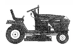

Owner's Manual
I'RBFTIMAN
16.5 HP
ELECTRIC START
42" MOWER
AUTOMATIC
LAWN TRACTQR
Model No.
917.271100
• Safety
• Assembly
• Operation
• Maintenance
• Repair Parts
1_ This product has a low emission engine which operates differently
from previously built engines. Before you start the engine, read
and understand this Owner's Manual.
CAUTION:
Read and follow all
Safety Rules and Instructions
before operating this equip-
ment.
For answers to your questions
about this product, Call:
1-800-659-5917
Sears Craftsman Help Line
5 am - 5 pm, Mon- Sat
Sears, Roebuck and Co., Hoffman Estates, IL 60179
Warranty .............. ,....,_ ................ 2
Safety Rules ........................................... 2
Product Specifications .._,.., .............. 5
Assembly ................................................ 8
Operation ............. ........ L.; ..................... 11
Maintenance Schedule ......................... 18 "
Maintenance ......................................... 18
Service and Adjustments ...................... 22
Storage .................................... -............ 28
Troubleshooting .................................... 29
• Repair Parts ......................................... 34
Parts Ordering ....................... Back Cover
LIMITED TWO YEAR WARRANTY ON CRAFTSMAN RIDING EQUIPMENT
For two (2) years from the date of purcllase, if this Craftsman Riding Equipment is main-
tained, lubricated and tuned up according to the instructions in the owner's manual,
Sears will repair or replace, free of char'ge, any parts found to be defective in material or
workmanship.
This Warranty does not cover:
• Expendable items which become worn during normal use, such as blades, spark
plugs, air cleaners, belts, etc.
• Tire replacement or repair caused by punctures from outside objects, such as nails,
thorns, stumps, or glass.
• Repairs necessary because of operator abuse, negligence, improper storage or acci-
dent or the failure to maintain the equipment according to the instructions contained in
the owner's manual.
• Riding equipment used for commercial or rental purposes.
LIMITED 90 DAY WARRANTY ON BA-I-rERY
For ninety (90) days from date of purchase, if any battery included with this riding equip-
ment proves defective in material or workmanship and our testing determines the bat-
tery will not hold a charge, Sears will replace the battery at no charge. In-home warranty
service on your Craftsman riding equipment is available at no charge for 30 days from
the date of purchase. Please contact your nearest service center. After 30 days from the
date of purchase, warranty service is available by taking your Craftsman riding equip-
ment to your nearest Sears Service Center. (In-home warranty service will still be avail-
able after 30 days from the date of purchase but a standard trip charge will apply). This
warranty applies only while this product is in the United States. This Warranty gives you
specific legal rights, and you may also have other rights which may vary from state to
state.
Sears, Roebuck and Co., D/817 WA, Hoffman Estates, IL 60179
GENERAL OPERATION
• Read, understand, and follow all instruc-
tions in the manual and on the machine
before starting.
• Only allow responsible adults, who are
familiar with the instructions, to operate
the machine.
• Clear the area of objects such as rocks,
toys, wire, etc., which could be picked
up and thrown by the blade.
• Be sure the area is clear of other people
before mowing. Stop machine if anyone
enters the area.
2
• Never carry passengers.
• Do not mow in reverse unless absolute-
ly necessary. Always look down and
behind before and while backing.
• Be aware of the mower discharge direc-
tion and do not point it at anyone. Do
not operate the mower without either
the entire grass catcher or the guard in
place.
• Slow down before turning.
• Never leave a running machine unat-
tended. Always turn off blades, set park-
ing brake, stop engine, and remove
keys before dismounting.
• Turnoft bladeswhennotmowing.
• Stopenginebeforeremovinggrass
catcheroruncloggingchute.
• Mowonly !n .dayl!ght or good artificial
light.
• Do not operate the machine While under
the influence of alcohol or drugs.
• Watch for traffic when operating near or
crossing roadways,
• Use extra€are when loading or unload-.
i_"g.the machine-int6_,_ tr&iler or truck.
SLOPE OPERATION _,
S opes are a major factor'related to loss-
of-control-and tipover accidents, which
can result in severe injury or death. All
slopes requ=re extra caution. If you cannot
hack up the slope or if you feel uneasy on
it, do not mow it.
DO:
• Mow up and down slopes, not across.
• Remove obstacles such as rocks, tree
limbs, etc.
• Watch for holes, ruts, or bumps. Uneven
terrain could overturn the machine. Tall
grass can hide obstacles.
. Use slow speed. Choose a low gear so
that you will not have to stop or shift
while on the slope.
• Follow the manufacturer's recommen-
dations for wheel weights or counter-
weights to improve stability.
• Use extra care with grass catchers or
other attachments. These can change
the stability of the machine.
• Keep all movement on the slopes slow
and gradual. Do not make sudden
changes in speed or direction.
• Avoid starting or stopping on a slope. If
tires lose traction, disengage the blades
and proceed slowly straight down the
slope.
DO NOT:
• Do not turn on slopes unless necessary,
and then, turn slowly and gradually
downhill, if possible.
• Do not mow near drop-ofts, ditches, or
embankments. The mower could sud-
denly turn over if a wheel is over the
edge of a cliff or ditch, or if an edge
caves in.
• Do not mow on wet grass. Reduced
traction could cause sliding.
• Do nottry to stabilize the machine by
putting your foot on the ground.
• Do not use grass catcher on steep-
slopes.
CHILDREN
Tragic accidents can occur if the operator
is not alert.to,the presence of children.
Children are often attracted to the
machine and themowing activity. Never
assume that childrenwill remainwhere
you last saw.them:L-:
;' Keep childre_.p_ of the mowing area
and under.the Watchful care of another
responsible.edult;"
• Be alert and turn machine oft if children
enter the area.
• Before and when backing, look behind
and down for small children.
• Never carry children. They may fall oft
and be seriously injured or interfere with
safe machine operation.
• Never allow children to operate the
machine.
• Use extra care when approaching blind
corners, shrubs, trees, or other objects
that may obscure vision.
SERVICE
• Use extra care in handling gasoline and
other fuels. They are flammable and
vapors are explosive.
Useonly an approved cQntainer.
Never remove gas cap or add fuel
with the engine running. Allow en-
gine to cool before refueling. Do not
smoke; • -
- Never refuel the machine indoors.
Never store the machine or fuel
container inside where there is an
open flame; such as a water' heater.
• Never run a machine inside a closed
area .......
• Keep nuts and bolts, especially blade
attachment bolts, tight and keep equip-
ment in good condition.
• Never tamper with safety devices.
Check their proper operation regularly.
• Keep machine free of grass, leaves, or
other debris build-up. Clean oil or fuel
spillage. Allow machine to cool before
storing.
• Stop and inspect the equipment if you
strike an object. Repair, if necessary,
3
beforerestarting.
• Never make adjustments or repairs with
the engine running.
• Grass catcher components are subject
to wear, damage, and deterioration,
which could expose moving parts or
allow objects to be thrown. Frequently
check components and replace with
manufacturer's recommended parts,
when necessary.
• Mower blades are sharp and can cut.
Wrap the blade(s) or wear gloves, and
use extra caution when servicing them.
• Check brake operation frequently.
Adjust and service as required.
• Be sure the area is clear of other people
before mowing. Stop machine if anyone
enters the area.
• Never carry passengers.
• Do not mow in reverse unless absolute-
ly necessary. Always look down and
behind before and while backing.
• Never carry children. They may fall off
and be seriously injured or interfere with
safe machine operation.
• Keep children out of the mowing area
and under the watchful care of another
responsible adult.
• • Be alert and tum machine off if children
enter the area.
• Before and when backing, look behind
and down for small children.
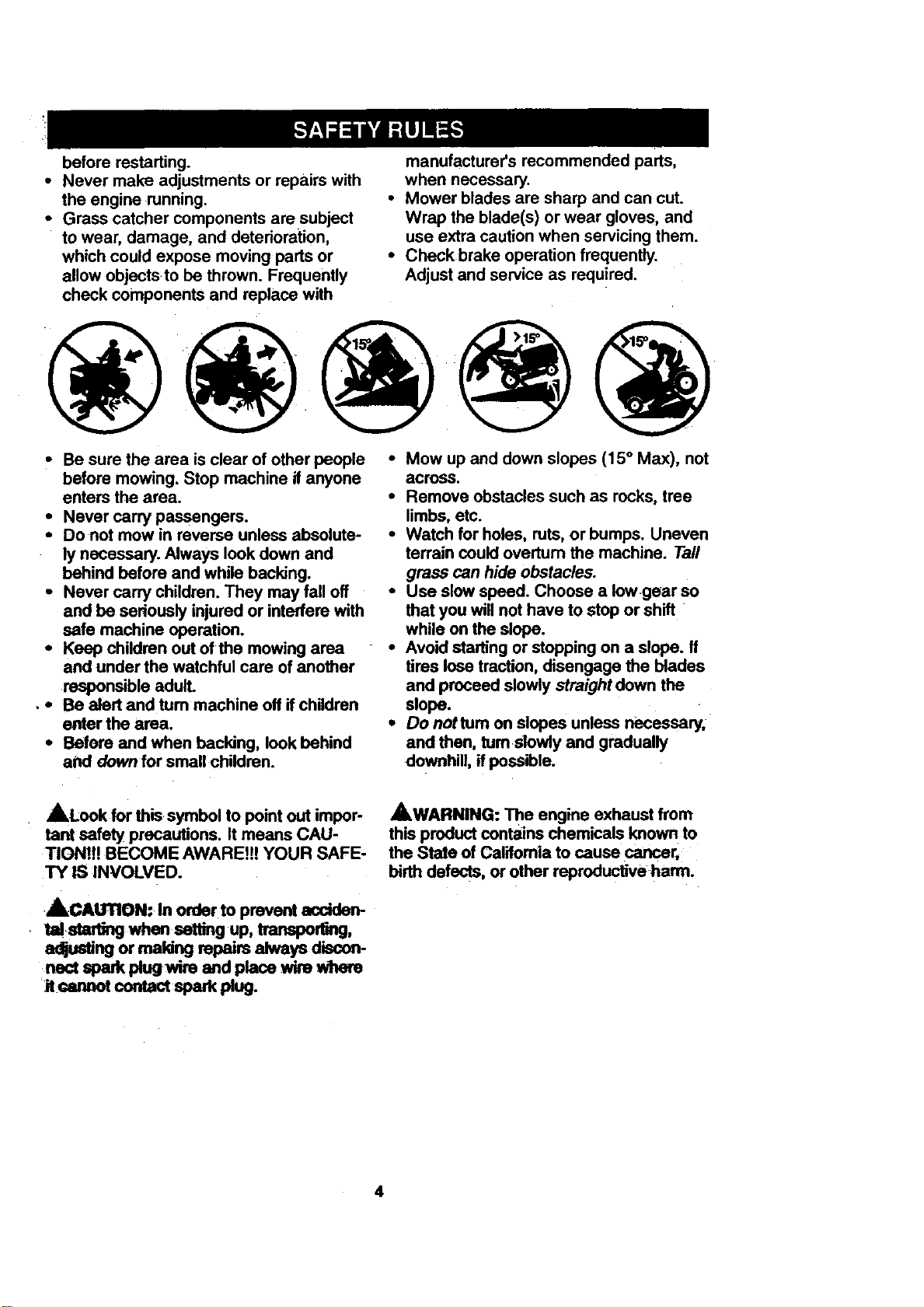
• Mow up and down slopes (15° Max), not
acroSS.
• Remove obstacles such as rocks, tree
limbs, etc.
• Watch for holes, ruts, or bumps. Uneven
terrain could overturn the machine. Tall
grass can hide obstacles.
• Use slow speed. Choose a low gear so
that you will not have to stop or shift
while on the slope.
• Avoid starting or stopping on a slope, tf
tires lose traction, disengage the blades
and proceed slowly straight down the
slope.
• Do nottum on slopes unless necessary,
and then, turn slowly and gradually
downhill, if possible.
_,Look for this symbol to point out impor-
tant safety precautions. It means CAU-
TION1H BECOME AWARE!!! YOUR SAFE-
TY IS INVOLVED.
•ACAUrTION: In order to prevent acciden-
star g when up,Vanapo go
a=rjustingormakingrepairsalwaysdiscon-
nectspark plug wire and place wire where
itcw= otco.tactsparkr ug.
_.WARNING: The engine exhaust from
this product contains chemicals known to
the State of California to cause cancer,
birth defects, or other roproductive harm.
4
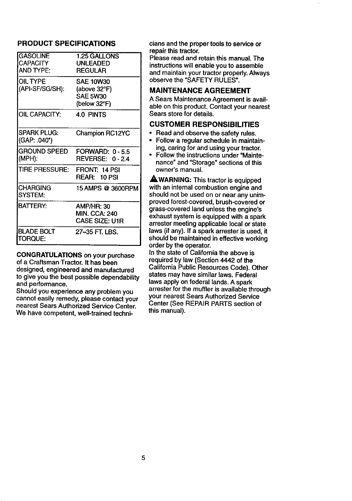
PRODUCT SPECIFICATIONS
GASOLINE 1.25GAllONS
CAPACITY UNLEADED
_,NDTYPE: REGUL/_R
OIL TYPE SAE 10W30
API-SF/SG/SH): (above 32°F)
SAE 5W30
(below 32°F)
OIL CAPACITY: 4.0 PINTS
SPARK PLUG: Champion RC12YC
GAP: .040")
GROUND SPEED FORWARD: 0-5.5
(MPH): REVERSE: 0-2.4
TIRE PRESSURE: FRONT: 14PSI
REAR: 10 PSI
CHARGING 15 AMPS @ 3600RPM
SYSTEM:
BATTERY: AMP/HR: 30
MIN. CCA: 240
CASE SIZE: U1R
BLADE BOLT 27-35 FT. LBS.
TORQUE:
CONGRATULATIONS on your purchase
of a Craftsman-Tractor. It has been
designed, engineered and manufactured
to give you the best possible dependability
and performance.
Should you experience any problem you
cannot easily remedy, please contact your
nearest Sears Authorized Service Center.
We have competent, well-trained techni-
clans and the proper tools to service or
repair this tractor.
Please read and retain this manual. The
instructions will enable you to assemble
and maintain your tractor properly. Always
observe the "SAFETY RULES".
MAINTENANCE AGREEMENT
A Sears Maintenance Agreement is avail-
able on this product. Contact your nearest
Sears store for details.
CUSTOMER RESPONSIBILITIES
• Read and observe the safety rules.
• Follow a regular schedule in maintain-
ing, caring for and using your tractor.
• Follow the instructions under "Mainte-
nance" and "Storage" sections of this
owner's manual.
,_,WARNING: This tractor is equipped
with an internal combustion engine and
should not be used on or near any unim-
proved forest-covered, brush-covered or
grass-covered land unless the engine's
exhaust system is equipped with a spark
arrester meeting applicable local or state
laws (if any). If a spark arrester is used, it
should be maintained in effective working
order by the operator.
In the state of California the above is
required by law (Section 4442 of the
California Public Resources Code). Other
states may have similar laws. Federal
laws apply on federal lands. A spark
arrester for the muffler is available through
your nearest Sears Authorized Service
Center (See REPAIR PARTS section of
this manual).
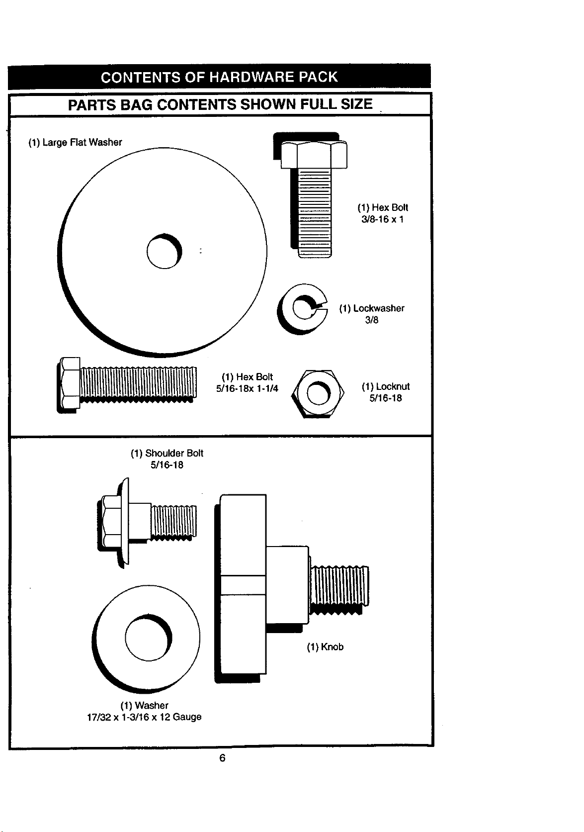
PARTS BAG CONTENTS SHOWN FULL SIZE
(1) Large Rat Washer
(1) Hex Bolt
3/8-16 x t
(1) Lockwasher
3/8
(1) Hex Bolt
5/16-18x 1-114 (1) Locknut
5/16-18
(1) Shoulder Bolt
5/16-18
©
(1) Knob
(1) Washer
17/32 x 1-3/16 x 12 Gauge
6
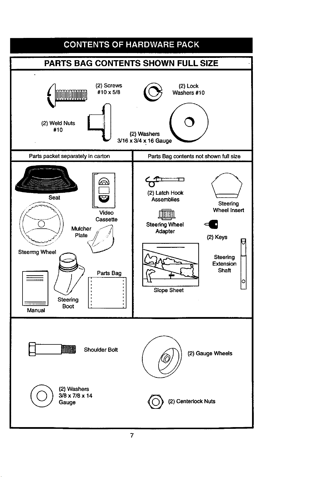
PARTS BAG CONTENTS SHOWN FULL SIZE
(_ (2)Screws _ (2)Lock
#10 x 518 Washers #10
#10 (2) Washers
3/16 x 3/4 x 16 Gauge "_,,,"
Parts packet separately in carton
Seat
Parts Bag contentsnot shownfull size
( ,I=T-----_
L)
(2) Latch Hook
Assemblies
_m
E3
Video
Cassette
Mulcher ,J__
Plate_!/ ;.//_
Steermg Whee_
Steering
Boot
Manual
Parts Bag
i =
i
i
i
D u
i
0
0
I
Steering Wheel
Adapter
I
Slope Sheet
Steering
Wheel Insert
-4=
(2) Keys E
Steering =
E_ension
Shaft
0
©
Shoulder Bolt
(2) Washers
3/8 x 7/8 x 14
Gauge
(2) Gauge Wheels
G (2) Centedock Nuts
7
Yournewtractorhasbeenassembledatthefactorywithexception of those parts left
unassembled for shipping purposes. To ensure safe and proper operation of your tractor
all parts and hardware you assemble must be tightened securely. Use the correct tools
as necessary to insure proper tightness. Review the video cassette before you begin.
TOOLS REQUIRED FOR
ASSEMBLY
A socket wrench set will make assembly
easier. Standard wrench sizes you need
are listed below.
(1) 9/16" Wrench (1) 3/4" Socket w/
(1) Pliers- drive rachet
(2) 1/2" wrench (1) Phillips Screw°
(1) Utility knife driver
(1) Tire pressure gauge (1) 3/4" wrench
When right or left hand is mentioned in
this manual, it means, from your point of
view, when you are in the operating posi-
tion (seated behind the steering wheel).
TO REMOVE TRACTOR FROM
CARTON
UNPACK CARTON
• Remove all accessible loose parts and
parts boxes from shipping carton (See
page 6).
• Cut, from top to bottom, along lines on
all four comers of shipping carton, and
lay panels flat.
• Check forany additional loose parts or
boxes and remove.
BEFORE ROLLING TRACTOR OFF
SKID
ATTACH STEERING WHEEL
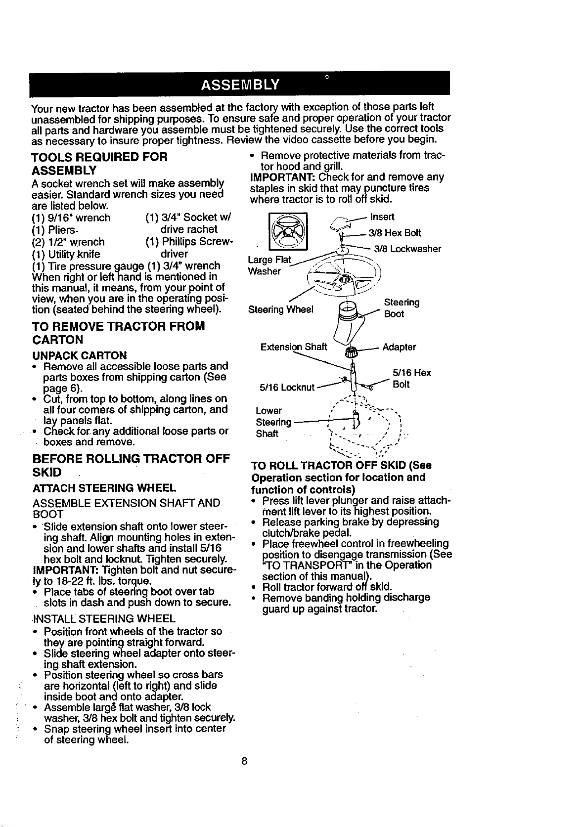
ASSEMBLE EXTENSION SHAFT AND
BOOT
• Slide extension shaft onto lower steer-
ing shaft. Align mounting holes in exten-
sion and lower shafts and install 5/16
hex bolt and Iocknut. Tighten securely.
IMPORTANT: Tighten bolt and nut secure-
ly to 18-22 ft. Ibs. torque.
• Place tabs of steering boot over tab
slots in dash and push down to secure.
INSTALL STEERING WHEEL
• Position front wheels of the tractor so
they are pointing straight forward.
• Slide steering wheel adapter onto steer-
ing shaft extension.
i Position steering wheel so cross bars
are horizontal (left to right) and slide
inside boot and onto adapter.
Assemble larg_ flat washer, 318 lock
, washer, 3/8 hex bolt and tighten securely.
• Snap steering wheel insert into center
of steering wheel.
• Remove protective materials from trac-
tor hood and grill.
IMPORTANT: Check for and remove any
staples in skid that may puncture tires
where tractor is to roll off skid.
_ Insert
Washer ___))
_ _ Steedng
Steering Wheel _ Boot
Extension__Shaft vl_.-._ Adapter
°c_knut _ .-=_'_ _'" 5/16 Hex5/16 L Bolt
Lower " ' "_-'-'-"
Steedng_ " ""
/P
Shaft _-._ ":, /
<.-. . ,-
TO ROLL TRACTOR OFF SKID (See
Operation section for location and
function of controls)
• Press lift lever plunger and raise attach-
ment lift lever to its highest position.
• Release parking brake by depressing
clutch/brake pedal.
• Place freewheel control in freewheeling
position to disengage transmission (See
=TO TRANSPORT" in the Operation
section of this manual).
• Roll tractor forward offskid.
• Remove banding holding discharge
guard up against tractor.
8
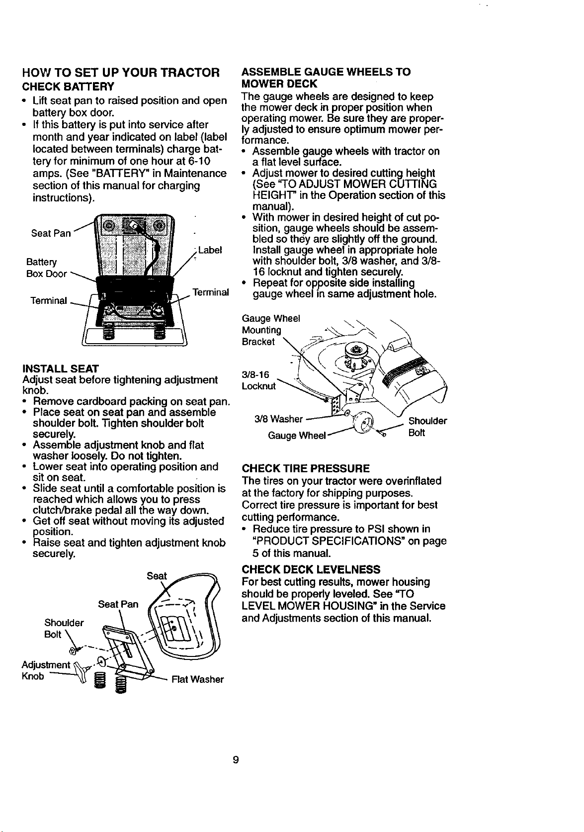
HOW TO SET UP YOUR TRACTOR
CHECK BATTERY
• Lift seat pan to raised position and open
battery box door.
• If this battery is put into service after
month and year indicated on label (label
located between terminals) charge bat-
tery for minimum of one hour at 6-10
amps. (See "BATFERY" in Maintenance
section of this manual for charging
instructions).
Se_
Ba_e_
Box
Label
Terminal
INSTALL SEAT
Adjust seat before tightening adjustment
knob.
• Remove cardboard packing on seat pan.
• Place seat on seat pan and assemble
shoulder bolt. Tighten shoulder bolt
securely.
• Assemble adjustment knob and flat
washer loosely. Do not tighten.
• Lower seat into operating position and
sit on seat.
• Slide seat until a comfortable position is
reached which allows you to press
clutch/brake pedal all the way down.
• Get off seat without moving its adjusted
position.
• Raise seat and tighten adjustment knob
securely.
Seat
Seat Pan
Shoulder
Bolt \
ASSEMBLE GAUGE WHEELS TO
MOWER DECK
The gauge wheels are designed to keep
the mower deck in proper position when
operating mower. Be sure they are proper-
ly adjusted to ensure optimum mower per-
formance.
• Assemble gauge wheels with tractor on
a flat level surface.
• Adjust mower to desired cutting height
(See "TO ADJUST MOWER CUFFING
HEIGHT" in the Operation section of this
manual).
• With mower in desired height of cut po-
sition, gauge wheels should be assem-
bled so they are slightly off the ground.
Install gauge wheel in appropriate hole
with shoulder bolt, 3/8 washer, and 3/8-
16 Iocknut and tighten securely.
• Repeat for opposite side installing
gauge wheel in same adjustment hole.
Gauge Wheel
Mounting
Bracket
3/8-16
3/8 Washer Shoulder
Gauge Wheel Bolt
CHECK TIRE PRESSURE
The tires on your tractor were overinflated
at the factory for shipping purposes.
Correct tire pressure is important for best
cutting performance.
• Reduce tire pressure to PSI shown in
"PRODUCT SPECIFICATIONS" on page
5 of this manual.
CHECK DECK LEVELNESS
For best cutting results, mower housing
should be propedy leveled. See "TO
LEVEL MOWER HOUSING" in the Service
and Adjustments section of this manual.
Adjustment
Knob
Flat Washer
9
CHECKFORPROPERPOSITIONOF
ALL BELTS
See the figures that are shown for replac-
ing motion and mower blade drive belts in
the Service and Adjustments sectoin of
this manual. Verify that the belts are rout-
ed correctly.
CHECK BRAKE SYSTEM
After you learn how to operate your trac-
tor, check to see that the brake is properly
adjusted. See =TO ADJUST BRAKE" in
the Service and Adjustments section of
this manual.
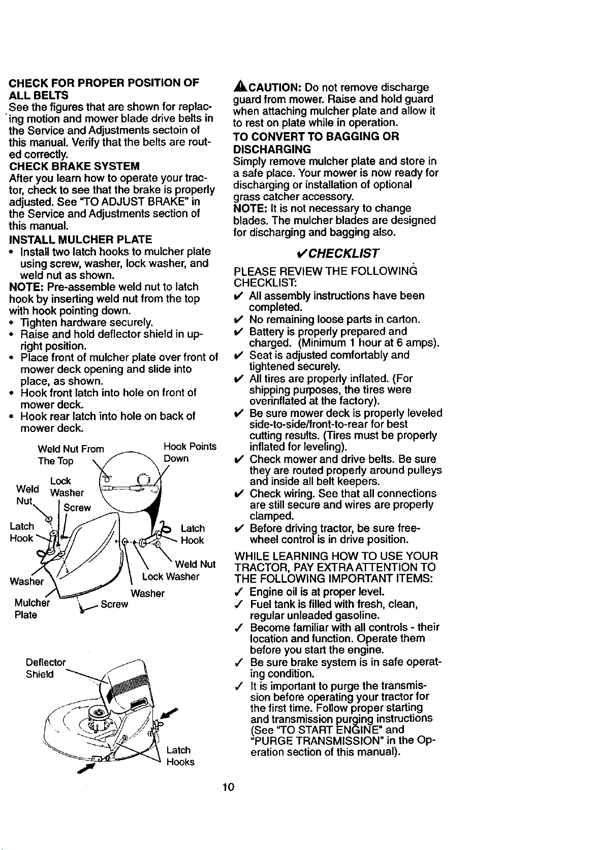
INSTALL MULCHER PLATE
• Install two latch hooks to mulcher plate
using screw, washer, lock washer, and
weld nut as shown.
NOTE: Pre-assemble weld nut to latch
hook by inserting weld nut from the top
with hook pointing down.
• Tighten hardware securely.
• Raise and hold deflector shield in up-
right position.
• Place front of mulcher plate over front of
mower deck opening and slide into
place, as shown.
• Hook front latch into hole on front of
mower deck.
• Hook rear latch into hole on back of
mower deck.
Weld Nut From Hook Points
The Top Down
Lock
Weld Washer
Latch Latch
Hook
Washer Lock Washer
Washer
Mulcher '_Screw
Plate
Deflector
Shield
Latch
Hooks
_,CAUTION: Do not remove discharge
guard from mower. Raise and hold guard
when attaching mulcher plate and allow it
to rest on plate while in operation.
TO CONVERT TO BAGGING OR
DISCHARGING
Simply remove mulcher plate and store in
a safe place. Your mower is now ready for
discharging or installation of optional
grass catcher accessory.
NOTE: It is not necessary to change
blades. The mulcher blades are designed
for discharging and bagging also.
t/CHECKLIST
PLEASE REVIEW THE FOLLOWIN(3
CHECKLIST:
v' All assembly instructions have been
completed.
t/ No remaining loose parts in carton.
v' Battery is properly prepared and
charged. (Minimum 1 flour at 6 amps).
v' Seat is adjusted comfortably and
tightened securely.
v' All tires are properly inflated. (For
shipping purposes, the tires were
overinflated at the factory).
v' Be sure mower deck is properly leveled
side-to-side/front-to-rear for best
cutting results. (Tires must be properly
inflated for leveling).
v' Check mower and drive belts. Be sure
they are routed properly around pulleys
and inside all belt keepers.
Check wiring. See that all connections
are still secure and wires are properly
clamped.
v' Before driving tractor, be sure free-
wheel control is in drive position.
WHILE LEARNING HOW TO USE YOUR
TRACTOR, PAY EXTRA ATTENTION TO
THE FOLLOWING IMPORTANT ITEMS:
/ Engine oil is at proper level.
,I Fuel tank is filled with fresh, clean,
regular unleaded gasoline.
,/ Become familiar with all controls - their
location and function. Operate them
before you start the engine.
,/ Be sure brake system is in safe operat-
ing condition.
,/ It is important to purge the transmis-
sion before operating your tractor for
the first time. Follow proper starting
and transmission purging instructions
(See "TO START ENGINE" and
"PURGE TRANSMISSION" in the Op-
eration section of this manual).
10
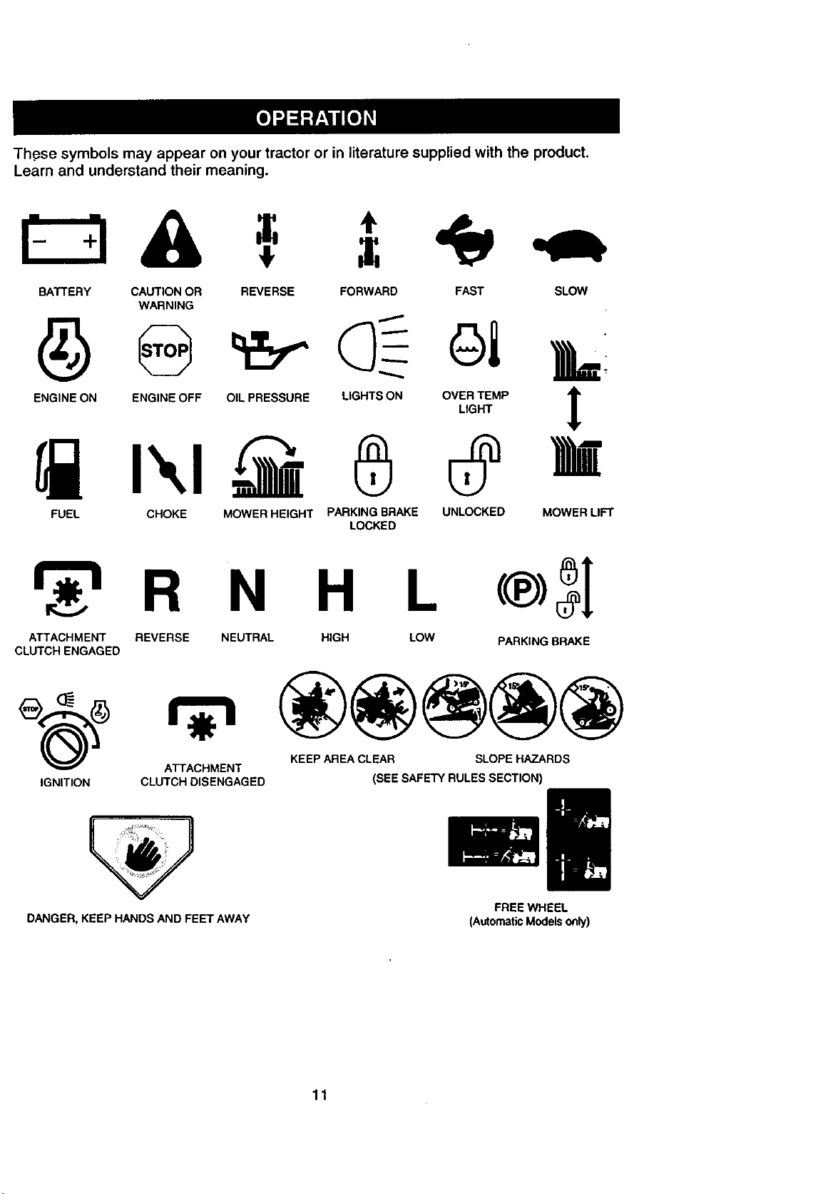
Th.esesymbolsmay appear on your tractor or in literature supplied with the product.
Learn and understand their meaning.
BATTERY CAUTION OR
WARNING
REVERSE FORWARD FAST SLOW
I
ENGINE ON ENGINE OFF OIL PRESSURE
A
LIGHTS ON OVER TEMP Ir
LIGHT
t
FUEL CHOKE MOWER HEIGHT PARKING BRAKE UNLOCKED MOWER LIFT
LOCKED
R N H L
ATTACHMENT REVERSE NEUTRAL HIGH LOW PARKING BRAKE
CLUTCH ENGAGED
KEEP AREA CLEAR SLOPE HAZARDS
ATTACHMENT
IGNITION CLUTCH DISENGAGED (SEE SAFETY RULES SECTION)
DANGER, KEEP HANDS AND FEET AWAY
FREEWHEEL
(A_omat_ Mode_on_)
11
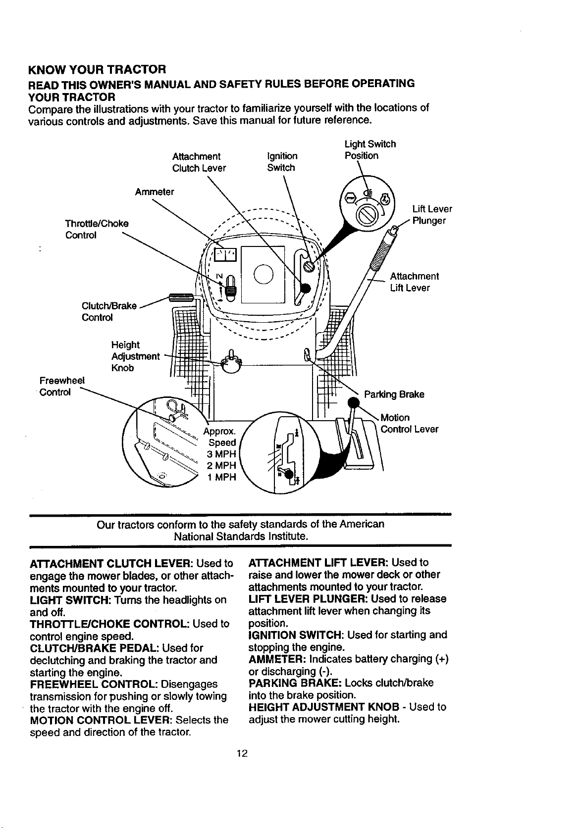
KNOW YOUR TRACTOR
READTHISOWNER'SMANUALANDSAFETYRULESBEFOREOPERATING
YOURTRACTOR
Compare the illustrations with your tractor to familiarize yourself with the locations of
various controls and adjustments. Save this manual for future reference.
LightSwitch
Position
'_ Lift Lever
Plunger
Attachment
Lift Lever
Parking Brake
Control Lever
Our tractors conform to the safety standards of the American
National Standards Institute.
ATTACHMENT CLUTCH LEVER: Used to
engage the mower blades, or other attach-
ments mounted to your tractor.
LIGHT SWITCH: Turns the headlights on
and off.
THROTTLE/CHOKE CONTROL: Used to
control engine speed.
CLUTCWBRAKE PEDAL: Used for
declutching and braking the tractor and
starting the engine.
FREEWHEEL CONTROL: Disengages
transmission for pushing or slowly towing
the tractor with the engine off.
MOTION CONTROL LEVER: Selects the
speed and direction of the tractor.
ATTACHMENT LIFT LEVER: Used to
raise and lower the mower deck or other
attachments mounted to your tractor.
LIFT LEVER PLUNGER: Used to release
attachment lift lever when changing its
position.
IGNITION SWITCH: Used for starting and
stopping the engine.
AMMETER: Indicates battery charging (+)
or discharging (-).
PARKING BRAKE: Locks clutch/brake
into the brake position.
HEIGHT ADJUSTMENT KNOB - Used to
adjust the mower cutting height.
12
The operation of any tractor can result in foreign objects thrown into the
eyes, which can result in severe eye damage. Always wear safety glasses
or eye shie ds wh e operat ng yoqr tractor or performing any adjustments or
repairs. We recommend a wide vision safety mask over spectacles, or stan-
dard safety glasses.
HOW TO USE YOUR TRACTOR
Your tractor is equipped with an operator
presence sensing switch. When engine is
running, any attempt by the operator to
leave the seat without first setting the
parking brake will shut off the engine.
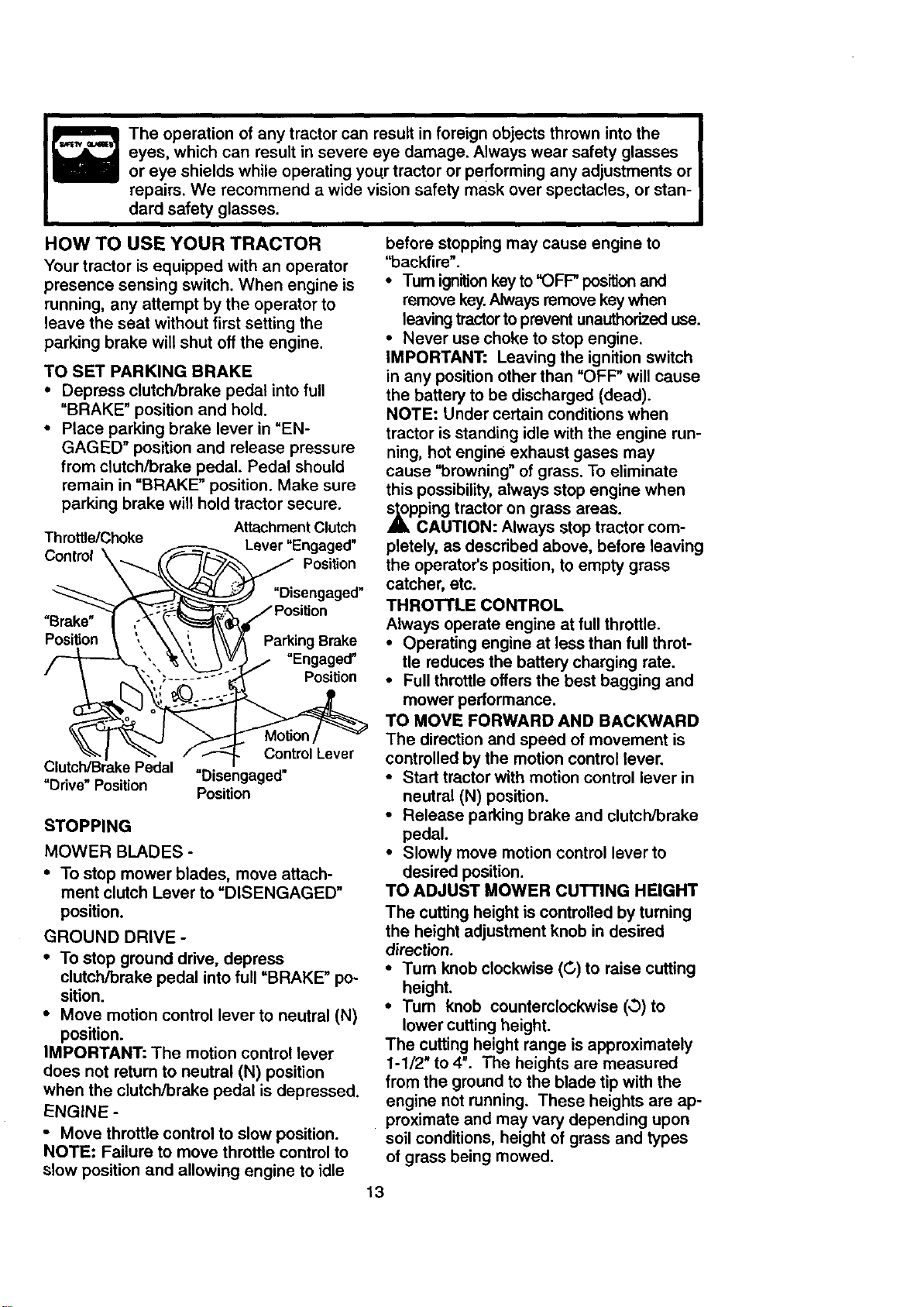
TO SET PARKING BRAKE
• Depress clutch/brake pedal into full
"BRAKE" position and hold.
• Place parking brake lever in "EN-
GAGED" position and release pressure
from clutch/brake pedal. Pedal should
remain in "BRAKE" position. Make sure
parking brake will hold tractor secure.
Attachment Clutch
Throttle/Choke Lever "Engaged"
Control \ Position
"Brake"
Position
"Disengaged"
Parking Brake
"Engaged"
Position
Control Lever
Clutch/Brake Pedal
"Ddve" Position "Disengaged"
Position
STOPPING
MOWER BLADES -
• To stop mower blades, move attach-
ment clutch Lever to "DISENGAGED"
position.
GROUND DRIVE -
• To stop ground drive, depress
clutch/brake pedal into full =BRAKE" po-
sition.
• Move motion control lever to neutral (N)
position.
IMPORTANT: The motion control lever
does not return to neutral (N) position
when the clutch/brake pedal is depressed.
ENGINE -
• Move throttle control to slow position.
NOTE: Failure to move throttle control to
slow position and allowing engine to idle
before stopping may cause engine to
"backfire".
•Tum ignitionkey to "OFP position and
remove key.Always remove key when
leaving tractor to prevent unauthorized use.
• Never use choke to stop engine.
IMPORTANT: Leaving the ignition switch
in any position other than "OFP will cause
the battery to be discharged (dead).
NOTE: Under certain conditions when
tractor is standing idle with the engine run-
ning, hot engine exhaust gases may
cause "browning" of grass. To eliminate
this possibility, always stop engine when
_tl_pping tractor on grass areas.
CAUTION: Always stop tractor com-
pletely, as described above, before leaving
the operator's position, to empty grass
catcher, etc.
THROTTLE CONTROL
Always operate engine at full throttle.
• Operating engine at less than full throt-
tle reduces the battery charging rate.
• Full throttle offers the best bagging and
mower performance.
TO MOVE FORWARD AND BACKWARD
The direction and speed of movement is
controlled by the motion control lever.
• Start tractor with motion control lever in
neutral (N) position.
• Release parking brake and clutch/brake
pedal.
• Slowly move motion control lever to
desired position.
TO ADJUST MOWER CUTTING HEIGHT
The cutting height is controlled by turning
the height adjustment knob in desired
direction.
• Turn knob clockwise (C,) to raise cutting
height.
• Turn knob counterclockwise (,,3) to
lower cutting height.
The cutting height range is approximately
1-1/2" to 4". The heights are measured
from the ground to the blade tip with the
engine not running. These heights are ap-
proximate and may vary depending upon
soil conditions, height of grass and types
of grass being mowed.
13
• The average lawn should be cut to
approximately 2-1/2 inches during the
cool season and to over 3 inches during
hot months. For healthier and better
looking lawns, mow often and after
moderate growth.
• For best cutting performance, grass
over 6 inches in height should be
mowed twice. Make the first cut rela-
tively high; the second to desired height.
TO OPERATE MOWER
Your tractor is equipped with an operator
presence sensing switch. Any attempt by
the operator to leave the seat with the
engine running and the attachment clutch
engaged will shut off the engine.
• Select desired height of cut.
• Lower mower with attachement lift con-
trol.
• Start mower blades by engaging attach-
ment clutch control.
• TO STOP MOWER BLADES - disen-
age attachment clutch control.
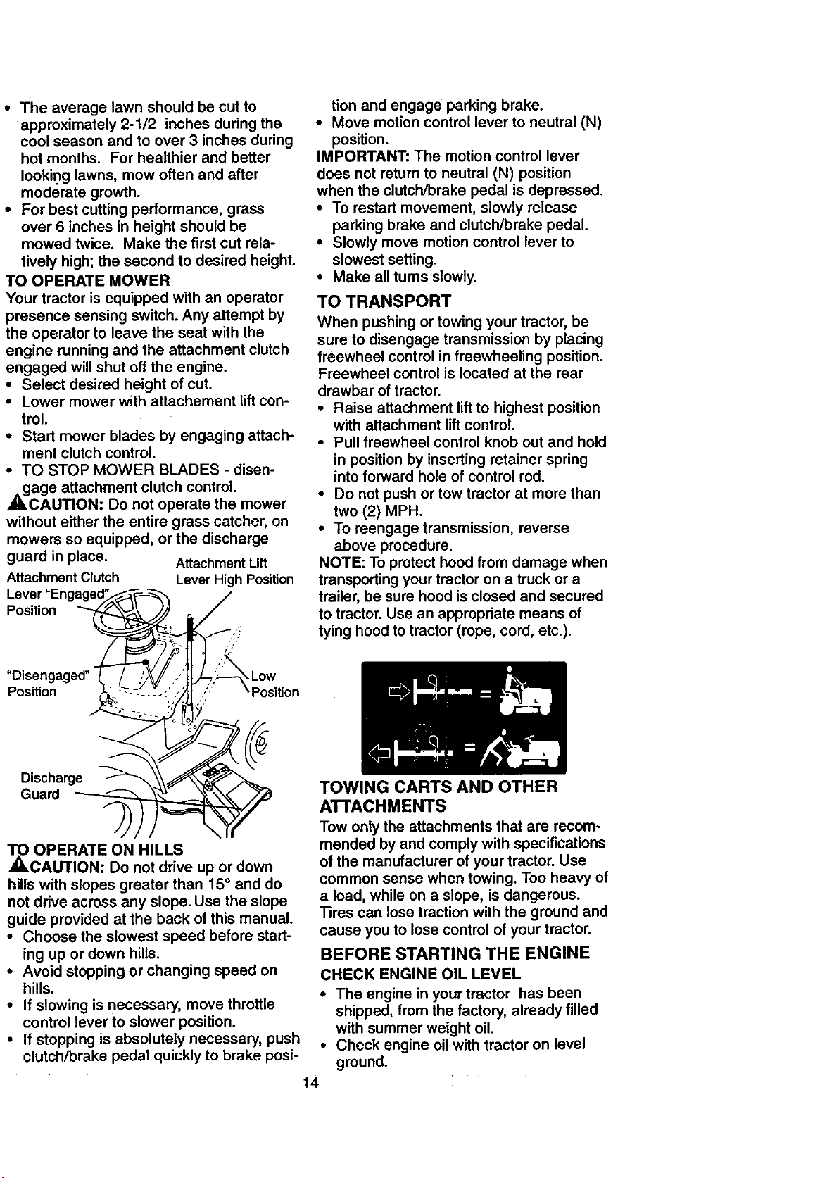
CAUTION; Do not operate the mower
without either the entire grass catcher, on
mowers so equipped, or the discharge
guard in place. Attachment Lift
Attachment Clutch Lever High Position
Lever "Engaged_ _ j
Position _-_ _, _" ,
pl_:_ngnaged _'_ L°witio n
_kO OPERATE ON HILLS
CAUTION: Do not drive up or down
hills with slopes greater than 15° and do
not drive across any slope. Use the slope
guide provided at the back of this manual.
• Choose the slowest speed before start-
ing up or down hills.
• Avoid stopping or changing speed on
hills.
• If slowing is necessary, move throttle
control lever to slower position.
• If stopping is absolutely necessary, push
clutch/brake pedal quickly to brake posi-
tion and engage parking brake.
• Move motion control lever to neutral (N)
position.
IMPORTANT: The motion control lever
does not return to neutral (N) position
when the clutch/brake pedal is depressed.
• To restart movement, slowly release
parking brake and clutch/brake pedal.
• Slowly move motion control lever to
slowest setting.
• Make all turns slowly.
TO TRANSPORT
When pushing or towing your tractor, be
sure to disengage transmission by placing
freewheel control in freewheeling position.
Freewheel control is located at the rear
drawbar of tractor.
• Raise attachment lift to highest position
with attachment lift control.
• Pull freewheel control knob out and hold
in position by inserting retainer spring
into forward hole of control rod.
• Do not push or tow tractor at more than
two (2) MPH.
• To reengage transmission, reverse
above procedure.
NOTE: To protect hood from damage when
transporting your tractor on a truck or a
trailer, be sure hood is closed and secured
to tractor. Use an appropriate means of
tying hood to tractor (rope, cord, etc.).
TOWING CARTS AND OTHER
ATTACHMENTS
Tow only the attachments that are recom-
mended by and comply with specifications
of the manufacturer of your tractor. Use
common sense when towing. Too heavy of
a load, while on a slope, is dangerous.
Tires can lose traction with the ground and
cause you to lose control of your tractor.
BEFORE STARTING THE ENGINE
CHECK ENGINE OIL LEVEL
• The engine in your tractor has been
shipped, from the factory, already filled
with summer weight oil.
• Check engine oil with tractor on level
ground.
14
• Unthread and remove oil fill cap/dip*
stick; wipe oil off. Reinsert the dipstick
into the tube and rest oil fill cap on the
tube. Do not thread the cap onto the
tube. Remove and read oil level. If nec-
essary, add oil until "FULL" mark on
dipstick is reached. Do not overfill.
• For cold weather operation you should
change oil for easier starting (See "OIL
VISCOSITY CHART" in the
Maintenance section of this manual).
• To change engine oil, see the
Maintenance section in this manual.
ADD GASOLINE
• Fill fuel tank. Use fresh, clean, regular
unleaded gasoline with a minimum of 87
octane. (Use of leaded gasoline will
increase carbon and lead oxide
deposits and reduce valve life). Do not
mix oil with gasoline. Purchase fuel in
quantities that can be used within 30
days to assure fuel freshness.
IMPORTANT: When operating in tempera-
tures below 32°F(0°C), use fresh, clean
winter grade gasoline to help insure good
_d weather starting.
WARNING: Experience indicates that
alcohol blended fuels (called gasohot or
using ethanol or methanol) can attract
moisture which leads to separation and
formation of acids during storage. Acidic
gas can damage the fuel system of an
engine while in storage. To avoid engine
problems, the fuel system should be emp-
tied before storage of 30 days or longer.
Drain the gas tank, start the engine and let
it run until the fuel lines and carburetor are
empty. Use fresh fuel next season. See
Storage Instructions for additional informa-
tion. Never use engine or carburetor
cleaner products in the fuel tank or perma-
_nt damage may occur.
CAUTION: Fill to bottom of gas tank
filler neck. Do not overfill. Wipe oft any
spilled oil or fuel. Do not store, spill or use
gasoline near an open flame.
TO START ENGINE
When starting the engine for the first time
or if the engine has run out of fuel, it will
take extra cranking time to move fuel from
the tank to the engine.
• Be sure freewheel control is in the
transmission engaged position.
• Sit on seat in operating I:_:_on, depress
dutch/brake pedal and set parkingbrake.
• Place motion control lever in neutral (N)
position.
• Move attachment clutch to "DISEN-
GAGED" position.
• Move throttle control to choke position.
NOTE: Before starting, read the warm and
cold starting procedures below.
• Insert key into ignition and turn key
clockwise to "START" position and
release key as soon as engine starts.
Do not run starter continuously for more
than fifteen seconds per minute. If the
engine does not start after several
attempts, move throttle control to fast
position, wait a few minutes and try
again. If engine still does not start,
move the throttle control back to the
choke position and retry.
WARM WEATHER STARTING (50 ° F and
above)
• When engine starts, move the throttle
control to the fast position.
• The attachments and ground drive can
now be used. If the engine does not
accept the load, restart the engine and
allow it to warm up for one minute using
the choke as described above.
COLD WEATHER STARTING ( 50 ° F and
below)
• When engine starts, allow engine to run
with the throttle control in the choke
position until the engine runs roughly.,
then move throttle control to fast pos=-
tion. This may require an engine warm-
up period from several seconds to sev-
eral minutes, depending on the temper-
ature.
AUTOMATIC TRANSMISSION WARM UP
• Before driving the unit in cold weather,
the transmission should be warmed up
as follows:
• Be sure the tractor is on level ground.
• Place the motion control lever in neutral.
Release the parking brake and let the
clutch/brake slowly return to operating
position.
• Allow one minute for transmission to
warm up. This can be done during the
engine warm up period.
• The attachments can also be used dur-
ing the engine warm-up period after the
transmission has been warmed up.
NOTE: At a high altitude (above 3000
feet) or in cold temperatures (below 32 F)
the carburetor fuel mixture may need to be
adjusted for best engine performance.
See "TO ADJUST CARBURETOR" in the
Service and Adjustments section of this
manual.
15
PURGETRANSMISSION
,_ CAUTION: Never engage or disen-
gage freewheel lever while the engine is
running. •
To ensure proper operation and perfor-
mance, it is recommended that the trans- •
mission be purged before operating tractor
for the first time, This procedure will
remove any trapped air inside the trans-
mission which may have developed during
shipping of your tractor. •
IMPORTANT: Should your transmission
require removal for service or replace- •
ment, it should be purged after reinstalla-
tion before operating the tractor.
• Place tr.actor safely on level surface with
engine off and parking brake set.
• Disengage transmission by placing free- •
wheel control in freewheeling position
(See =TO TRANSPORT" in this section
of manual).
• Sitting in the tractor seat, start engine.
After the engine is running, move throt-
tle control to slow position. With motion •
control lever in neutral (N) position,
slowly disengage clutch/brake pedal.
• Move motion control lever to full forward
position and hold for five (5) seconds.
Move lever to full reverse position and o
hold for five (5) seconds. Repeat this
procedure three (3) times.
NOTE: During this procedure there will be
no movement of drive wheels. The air is .
being removed from hydraulic drive sys-
tem.
• Move motion control lever to neutral (N)
position. Shut off engine and set parking
brake.
• Engage transmission by placing free-
wheel control in driving position (See o
=TO TRANSPORT" in this section of
manual).
• Sitting in the tractor seat, start engine.
After the engine is running, move throt-
tle control to half (1/2) speed. With
motion control lever in neutral (N) posi-
tion, slowly disengage clutch/brake
pedal.
• Slowly move motion control lever for-
ward; after the tractor moves approxi-
mately five (5) feet, slowly move motion
control lever to reverse position. After
the tractor mo0es approximately five (5)
feet return the motion control lever to
the neutral (N) position. Repeat this pro-
cedure with the motion control lever
three (3) times.
16
• Your tractor is now purged and ready for
normal operation.
MOWING TIPS
Tire chains cannot be used when the
mower housing is attached to tractor.
"Mower should be properly leveled for
best mowing performance. See "TO
LEVEL MOWER HOUSING" in the
Service and Adjustments section of this
manual.
The left hand side of mower should be
used for trimming.
Ddve so that clippings are d_t'k_rged onto
the area that has been cut. Have the cut area
to the rightof the tractor. This will result in a
more even cistrbutJon ofclippingsand more
uniform cutting.
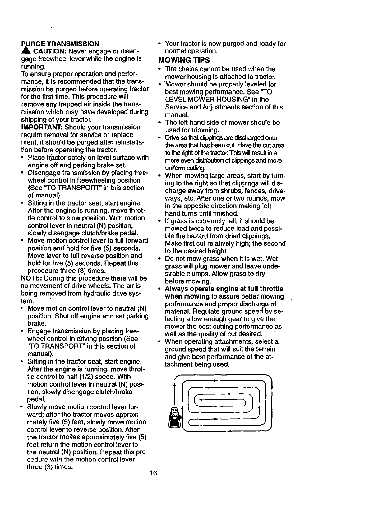
When mowing large areas, start by turn-
ing to the right so that clippings will dis-
charge away from shrubs, fences, drive-
ways, etc. After one or two rounds, mow
in the opposite direction making left
hand turns until finished.
If grass is extremely tall, it should be
mowed twice to reduce load and possi-
ble fire hazard from dried clippings.
Make first cut relatively high; the second
to the desired height.
Do not mow grass when it is wet. Wet
grass will plug mower and leave unde-
sirable clumps. Allow grass to dry
before mowing.
Always operate engine at full throttle
when mowing to assure better mowing
performance and proper discharge of
material. Regulate ground speed by se-
lecting a low enough gear to give the
mower the best cutting performance a s
well as the quality of cut desired.
When operating attachments, select a
ground speed that will suit the terrain
and give best performance of the at-
tachment being used.
f
MULCHING MOWING TIPS
IMPORTANT: For best performance, keep
mower housing free of built-up grass and
trash. Clean after each use.
• The special mulching blade .willrecut
the grass clippings many times and
reduce them in size so that as they fall
onto the lawn they will disperse into the
grass and not be noticed. Also, the
mulched grass will biodegrade quickly
to provide nutrients for the lawn. Always
mulch with your highest engine (blade)
speed as this will provide the best recut-
ting action of the blades.
• Avoid cutting your lawn when it is wet.
Wet grass tends to form clumps and
interferes with the mulching action. The
best time to mow your lawn is the early
afternoon. At this time the grass has
dried and the newly cut area will not be
exposed to the direct sun.
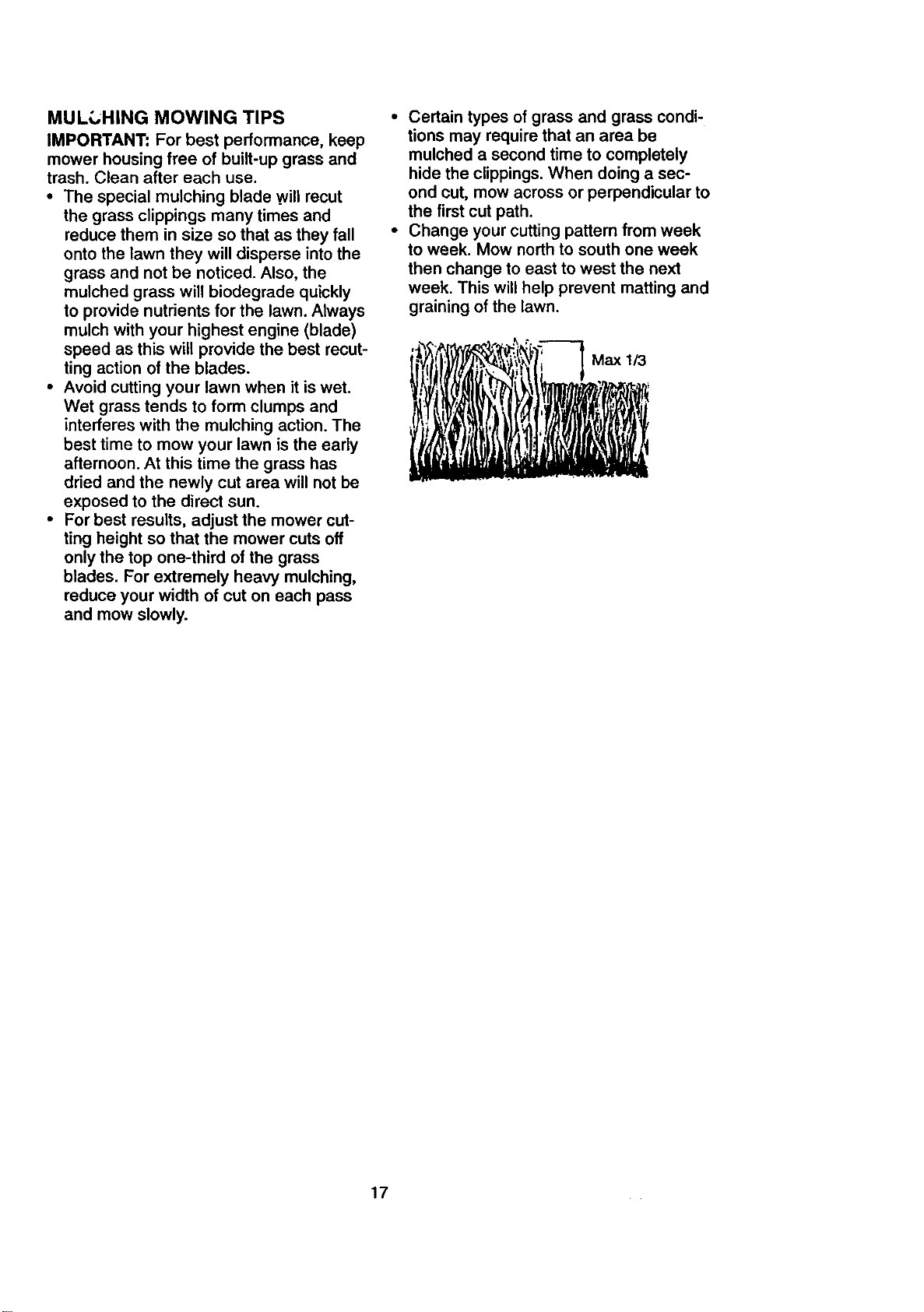
• For best results, adjust the mower cut-
ting height so that the mower cuts off
only the top one-third of the grass
blades. For extremely heavy mulching,
reduce your width of cut on each pass
and mow slowly.
• Certain types of grass and grass condi-
tions may require that an area be
mulched a second time to completely
hide the clippings. When doing a sec-
ond cut, mow across or perpendicular to
the first cut path.
• Change your cutting pattern from week
to week. Mow north to south one week
then change to east to west the next
week. This will help prevent matting and
graining of the lawn.
17
CUSTOMER RESPONSIBILITIES
FI'L,.OATEe
Check BrakeOperatfon _ k/
Check Tire Pressure I
,I
Check Operator Presence end
T I Interlock Systems !If
Check for Loose Fasteners IIf 11_7 I_
SllarperdReplaGe Mower Blades I_'4
Lubrication Chart " _ V'
0 Check Battery Level
R CleanB_=tteryandTerminals •
Check Transa)de Cooling V'
Adjust Blade Ek_it(s),Tension !I_€
Adlust Motion Drive Belt(s) Tension ! I_s
Check Engine Oil Level If Ik_
Change Engine Oil ,11_1_,: If
E Clean Air Filter
N Clean Air Screen
G Inspect Muffler/Spark Arrester V'
Replace Oil Filter (if equipped) =_=
N Clean Engine Cooling Fins
Replace Spark Plug _ I_/
Replace Air Filter Paper Cartridge I_=
Replace Fuel Filter II_
1 .Chcngemoreoftenwhenopera_gurtderlheavyk>adorinhighambienttemperatur_. 5-1feeu_Cedwlthadjustablesystem,
2 - Service more often when operating in _dy ordustycondif_on=.
3 - If _1 uipped wllh OUfitter, ¢=hange oil every 50 hour=.
4 - Replace b_ade$ mo_e often when mowfng _ sandy ==oil.
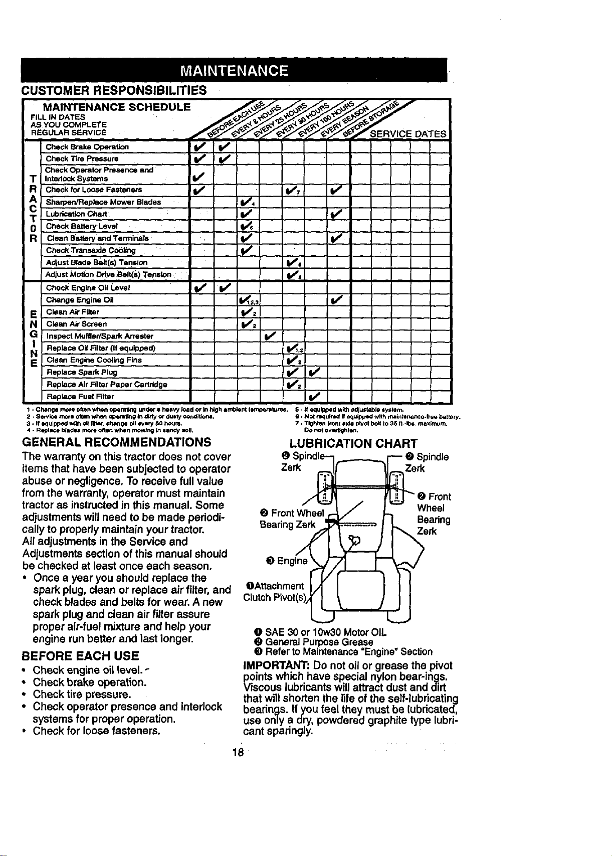
GENERAL RECOMMENDATIONS
The warranty on this tractor does not cover
items that have been subjected to operator
abuse or negligence. To receive full value
from the warranty, operator must maintain
tractor as instructed in this manual. Some
adjustments will need to be made periodi-
cally to properly maintain your tractor.
All adjustments in the Service and
Adjustments section of this manual should
be checked at least once each season.
• Once a year you should replace the
spark plug, clean or replace air filter, and
check blades and belts for wear. A new
spark plug and clean air filter assure
proper air-fuel mixture and help your
engine run better and last longer.
BEFORE EACH USE
• Check engine oil level.
• Check brake operation.
• Check tire pressure.
• Check operator presence and interlock
systems for proper operation.
• Check for loosefasteners.
6 - Not required if edutpped with maintenance-free battery.
7 - Tighten fronl a._depivot boll to 35 ft.-10s, maximum.
DO not or•flight an.
LUBRICATION CHART
@ Spindle--i..___-__.._i---- e Spindle
Zerk __rk
//_"" _ / r"W -- e Front
. ,on,WhBs,/ ooann he"lg
_ Engine _
OAttachment IA I I II
Clutch Pivol(s)_@_J
O SAE 30 or 10w30 Motor OIL
• General Purpose Grease
• Refer to Maintenance =Engine" Section
IMPORTANT: Do not oil or grease the pivot
points which have special nylon bear-ings.
Viscous lubricants will attract dust and dirt
that will shorten the life of the self-lubricating
bearings. If you feel they must be lubricated,
use only a dry, powdered graphite type lubri-
cant sparingly.
18¸
TRACTOR
Always observe safety rules when perform-
ing any maintenance.
BRAKE OPERATION
If tractor requires more than six (6) feet
stopping distance at high speed in highest
gear, then brake must be adjusted. (See
"TO ADJUST BRAKE" in the Service and
Adjustments section of this manual).
TIRES
• Maintain proper air pressure in all tires
(See "PRODUCT SPECIFICATIONS" on
page 3 of this manual).
• Keep tires free of gasoline, oil, or insect
control chemicals which can harm rub-
ber.
• Avoid stumps, stones, deep ruts, sharp
objects and other hazards that may
cause tire damage.
NOTE: To seal tire punctures and prevent
flat tires due to slow leaks, tire sealant may
be purchased from your local parts dealer.
Tire sealant also prevents tire dry rot and
corrosion.
OPERATOR PRESENCE SYSTEM
Be sure that operator presence and inter-
lock systems are working properly. If your
tractor does not function as described
below, repair the problem immediately.
• The engine should not start unless the
clutch/brake pedal is fully depressed and
attachment clutch control is in the disen-
gaged position.
• When the engine is running, any attempt
by the operator to leave the seat without
first setting the parking brake should shut
off the engine.
• When the engine is running and the
attachment clutch is engaged, any
attempt by the operator to leave the seat
should shut off the engine.
• The attachment clutch should never
operate unless the operator is in the
seat.
BLADE CARE
For best results mower blades must be
kept sharp. Replace bent or damaged
blades.
BLADE REMOVAL
• Raise mower to highest position to allow
access to blades,
• Remove hex bolt, lock washer and flat
washer securing blade.
• Install new or resharpened blade with
trailing edge up towards deck as shown.
19
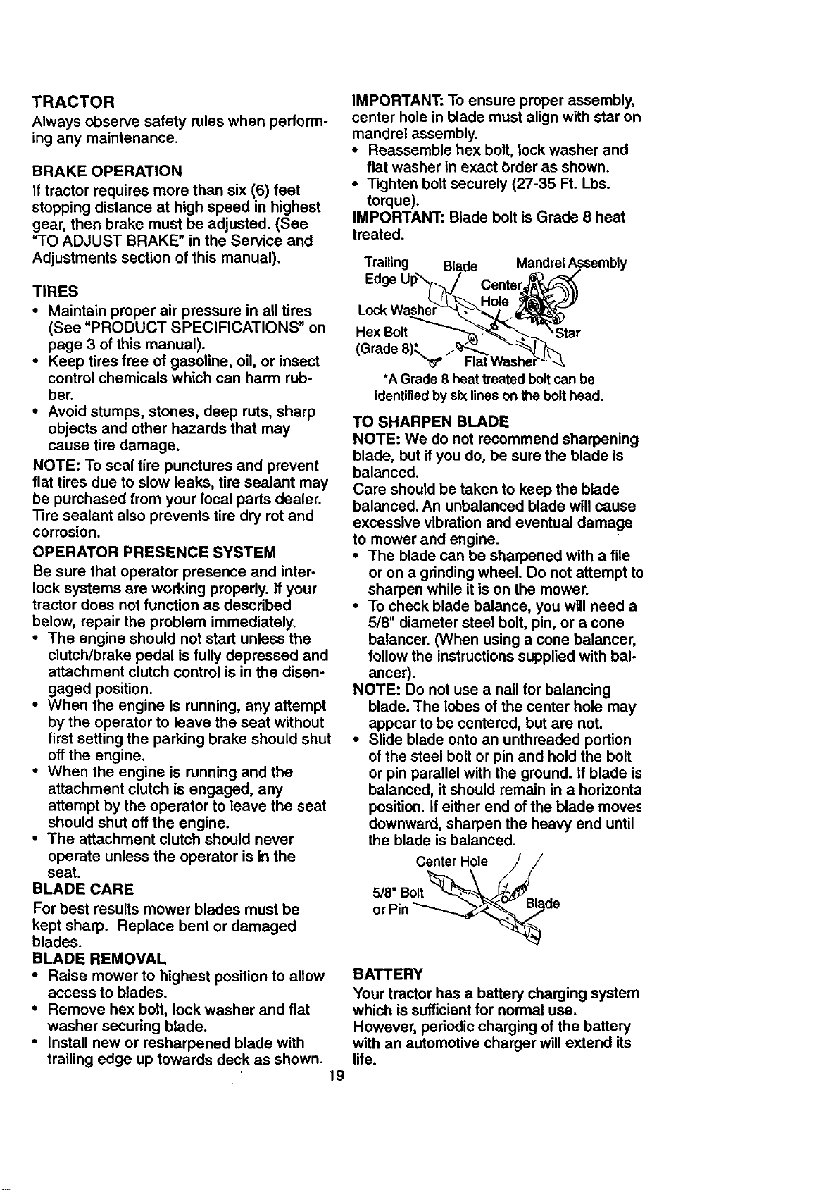
IMPORTANT: To ensure proper assembly,
center hole in blade must align with star on
mandrel assembly.
• Reassemble hex bolt, lock washer and
flat washer in exact Order as shown.
• Tighten bolt securely (27-35 Ft. Lbs.
torque).
IMPORTANT: Blade bolt is Grade 8 heat
treated.
Trailing Blade Mandrel A,_sembly
Edge Up_(_j/ Center_
•
(Grade 8)_. .-_*'J_ "_'_,,_,
"_ Flat Washer"_-_
•A Grade 8 heat treated boltcan be
identifiedby sixlineson the bolthead.
TO SHARPEN BLADE
NOTE: We do not recommend sharpening
blade, but if you do, be sure the blade is
balanced.
Care should be taken to keep the blade
balanced. An unbalanced blade will cause
excessive vibration and eventual damage
to mower and engine.
• The blade can be sharpened with a file
or on a grinding wheel. Do not attempt to
sharpen while it is on the mower.
• To check blade balance, you will need a
5/8" diameter steel bolt, pin, or a cone
balancer. (When using a cone balancer,
follow the instructions supplied with bal-
ancer).
NOTE: Do not use a nail for balancing
blade. The lobes of the center hole may
appear to be centered, but are not.
• Slide blade onto an unthreaded portion
of the steel bolt or pin and hold the bolt
or pin parallel with the ground. If blade is
balanced, it should remain in a horizonta
position, if either end of the blade move.,
downward, sharpen the heavy end until
the blade is balanced.
Center Hole
or Pin
BATTERY
Your tractor has a battery charging system
which is sufficient for normal use.
However, periodic charging of the battery
with an automotive charger will extend its
life.
• Keep battery and terminals clean.
• Keep battery bolts tight.
• Keep small vent holes open.
• Recharge at 6-10 amperes for 1 hour.
TO CLEAN BATTERY AND TERMINALS
Corrosion and dirt on the battery and ter-
minals can cause the battery to "leek"
power.
• Open battery box door.
• Disconnect BLACK battery cable first
then RED battery cable and remove
battery from tractor.
• Rinse the battery with plain water and
dry.
• Clean terminals and battery cable ends
with wire brush until bright.
• Coat terminals with grease or petroleum
jelly.
• Reinstall battery (See "REPLACING
BATTERY" in the SERVICE AND
ADJUSTMENTS section of this manu-
al).
V-BELTS
Check V-belts for deterioration and wear
after 100 hours of operation and replace if
necessary. The belts are not adjustable.
Replace belts if they begin to slip from
wear.
TRANSAXLE COOLING
The transmission fan and cooling fins
should be kept clean to assure proper
cooling.
Do not attempt to clean fan or transmis-
sion while engine is running or while the
transmission is hot.
• Inspect cooling fan to be sure fan
blades are intact and clean.
• Inspect cooling fins for dirt, grass clip-
pings and other materials. To prevent
damage to seals, do not use com-
pressed air or high pressure sprayer to
clean cooling fins.
TRANSAXLE PUMP FLUID
The transaxle was sealed at the factory
and fluid maintenance is not required for
the life of the transaxle. Should the
transaxle ever leak or require servicing,
contact your nearest authorized service
center.
_o" .t_e G* Im 20.
TIFMPIERATI _E RANGE ANT_"IPATEO BIEFO;_[ NEXT _L CItANG_
Change the oil after every 50 hours of
operation or at least once a year if the
tractor is not used for 50 hours in one
year.
Check the crankcase oil level before start-
ing the engine and after each eight (8)
hours ot operation. Tighten oil fill cap/dip-
stick securely each time you check the oil
level.
TO CHANGE ENGINE OIL
Determine temperature range expected
before oil change. All oil must meet API
service classification SF, SG, or SH.
• Be sure tractor is on level surface.
• Oil will drain more freely when warm.
• Catch oil in a suitable container.
• Remove oil fill cap/dipstick. Be careful
not to allow dirt to enter the engine
when changing oil.
• Remove drain plug.
• After oil has drained completely, replace
oil drain plug and tighten securely.
• Refill engine with oil through oil fill dip-
stick tube. Pour slowly. Do not overfill.
For approximate capacity see "PROD-
UCT SPECIFICATIONS" on page 3 of
this manual.
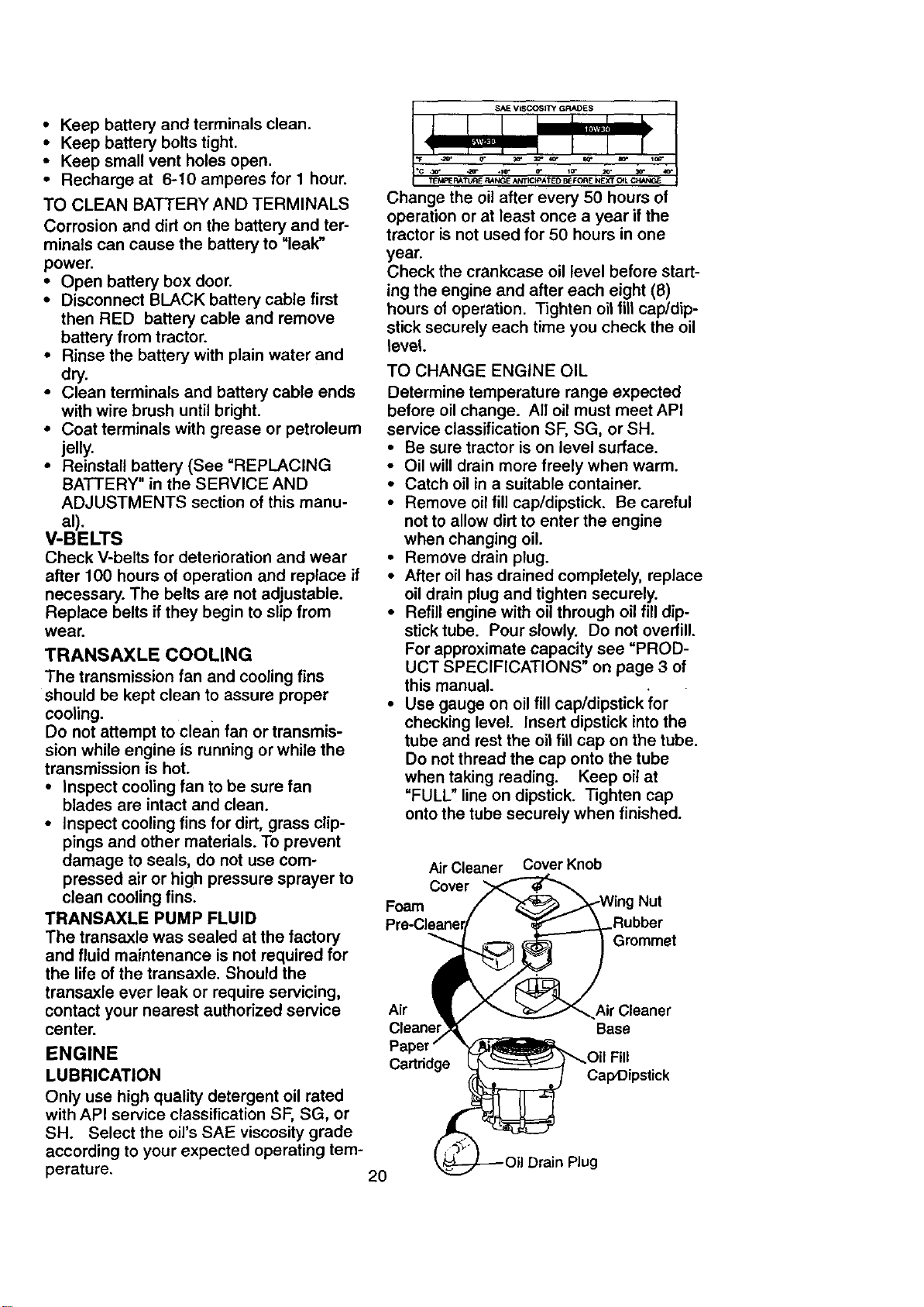
• Use gauge on oil fill cap/dipstick for
checking level. Insert dipstick into the
tube and rest the oil fill cap on the tube.
Do not thread the cap onto the tube
when taking reading. Keep oil at
"FULL" line on dipstick. Tighten cap
onto the tube securely when finished.
Air Cleaner
Cover
Foam
Cover Knob
Nut
:_ubber
Grommet
Air
Cleaner
Air Cleaner
Base
ENGINE
LUBRICATION
Only use high quality detergent oil rated
with API service classification SF, SG, or
SH. Select the oil's SAE viscosity grade
according to your expected operating tem-
perature. 20
Ca_ddge
Cap,Dipstick
CLEAN AIR SCREEN
Air screen must be kept free of dirt and
chaff to prevent engine damage from over-
heating. Clean with a wire brush or com-
pressed air to remove dirt and stubborn
dried gum fibers.
AIR FILTER
Your engine will not run properly using a
dirty air filter. Clean the foam pre-cleaner
after every 25 hours of operation or every
season. Service paper cartridge every
100 hours of operation or every season,
whichever occurs first.
Service air cleaner more often under dusty
conditions.
• Remove knob and cover.
• Remove wing nut and air cleaner from
base.
TO SERVICE PRE-CLEANER
• Slide foam pre-cleaner off cartridge.
• Wash it in liquid detergent and water.
• Squeeze it dry in a clean cloth. Allow it
to dry.
• Saturate it in engine oil. Wrap it in
clean, absorbent cloth and squeeze to
remove excess oil
TO SERVICE CARTRIDGE
• Replace a dirty, bent, or damaged car-
tridge.
NOTE: Do not wash the paper cartridge
or use pressurized air, as this will damage
the cartridge.
• Reinstall the pre-cleaner (cleaned
and oiled) over the paper car-
tridge.
• Reassemble air cleaner, wing nut,
cover and tighten knob securely.
CLEAN AIR INTAKE/COOLING AREAS
To insure proper cooling, make sure the
grass screen, cooling fins, and other
extemal surfaces of the engine are kept
clean at all times.
Every 100 hours of operation (more often
under extremely dusty, dirty conditions),
remove the blower housing and other
cooling shrouds. Clean the cooling fins
and external surfaces as necessary. Make
sure the cooling shrouds are reinstalled.
NOTE: Operating the engine with a
blocked grass screen, dirty or plugged
cooling fins, and/or cooling shrouds re-
moved will cause engine damage due to
overheating.
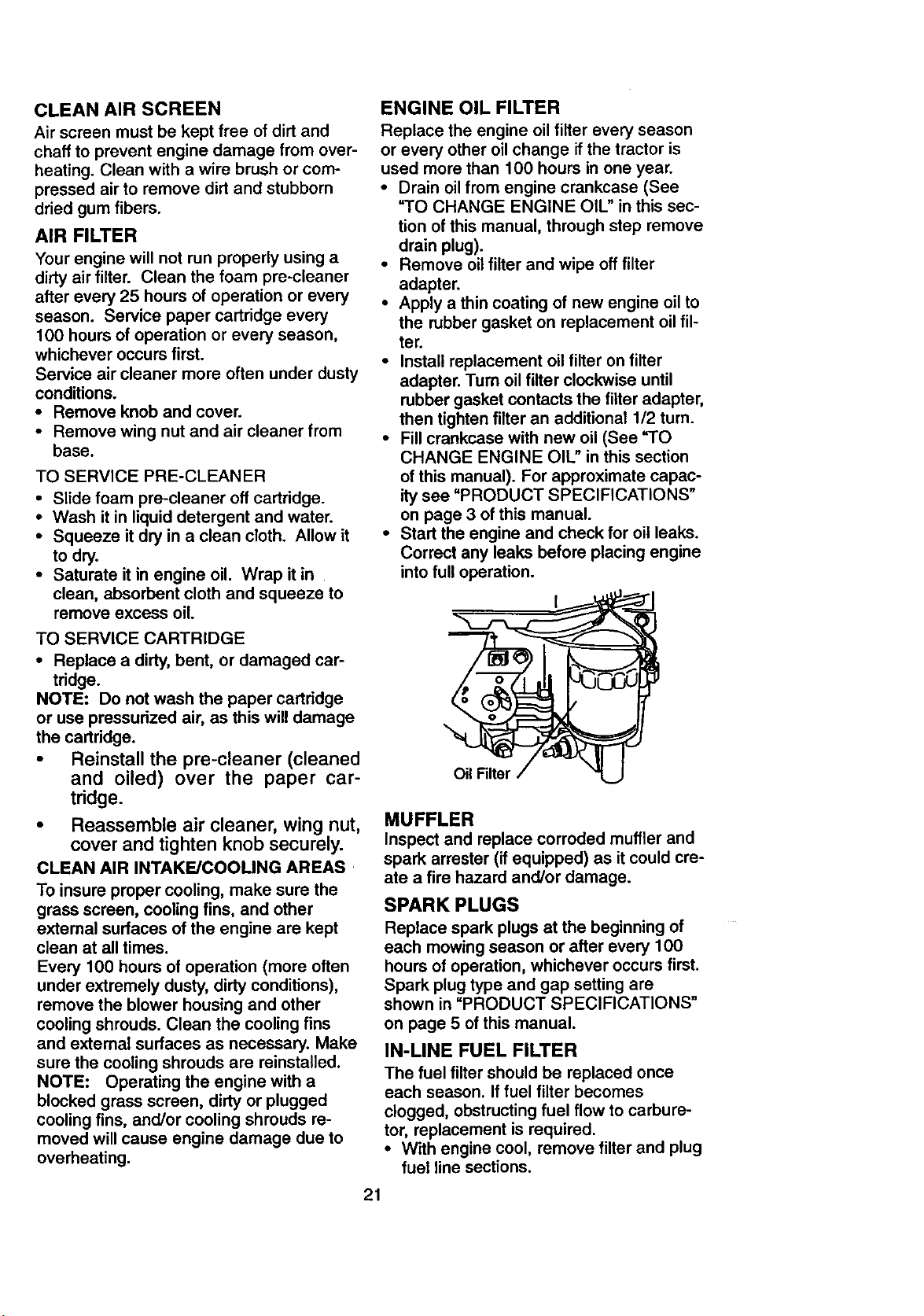
ENGINE OIL FILTER
Replace the engine oil filter every season
or every other oil change if the tractor is
used more than 100 hours in one year.
• Drain oil from engine crankcase (See
"TO CHANGE ENGINE OIL" in this sec-
tion of this manual, through step remove
drain plug).
• Remove oil filter and wipe off filter
adapter.
• Apply a thin coating of new engine oil to
the rubber gasket on replacement oil fil-
ter.
• Install replacement oil filter on filter
adapter. Tum oil filter clockwise until
rubber gasket contacts the filter adapter,
then tighten filter an additional 1/2 turn.
• Fill crankcase with new oil (See "TO
CHANGE ENGINE OIL" in this section
of this manual). For approximate capac-
ity see "PRODUCT SPECIFICATIONS"
on page 3 of this manual.
• Start the engine and check for oil leaks.
Correct any leaks before placing engine
into full operation.
MUFFLER
Inspect and replace corroded muffler and
spark arrester (if equipped) as it could cre-
ate a fire hazard and/or damage.
SPARK PLUGS
Replace spark plugs at the beginning of
each mowing season or after every 100
hours of operation, whichever occurs first.
Spark plug type and gap setting are
shown in "PRODUCT SPECIFICATIONS"
on page 5 of this manual.
IN-LINE FUEL FILTER
The fuel filter should be replaced once
each season. If fuel filter becomes
clogged, obstructing fuel flow to carbure-
tor, replacement is required.
• With engine cool, remove filter and plug
fuel line sections.
21
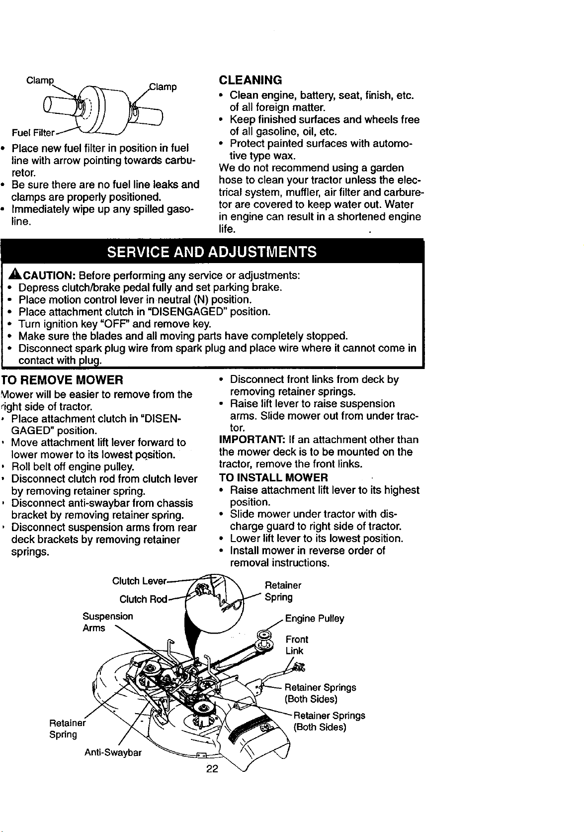
• Place new fuel filter in position in fuel
line with arrow pointing towards carbu-
retor.
• Be sure there are no fuel line leaks and
clamps are properly positioned.
• Immediately wipe up any spilled gaso-
line.
CLEANING
• Clean engine, battery, seat, finish, etc.
of all foreign matter.
• Keep finished surfaces and wheels free
of all gasoline, oil, etc.
• Protect painted surfaces with automo-
tive type wax.
We do not recommend using a garden
hose to clean your tractor unless the elec-
trical system, muffler, air filter and carbure-
tor are covered to keep water out. Water
in engine can result in a shortened engine
life.
_,CAUTION: Before performing any service or adjustments:
• Depress clutch/brake pedal fully and set parking brake.
• Place motion control lever in neutral (N) position.
• Place attachment clutch in "DISENGAGED" position.
• Turn ignition key "OFF" and remove key.
• Make sure the blades and all moving parts have completely stopped.
• Disconnect spark plug wire from spark plug and place wire where it cannot come in
contact with plu_].
TO REMOVE MOWER
Mower will be easier to remove from the
_ight side of tractor.
0 Place attachment clutch in "DISEN-
GAGED" position.
, Move attachment lift lever forward to
lower mower to its lowest pqsition.
, Roll belt off engine pulley.
• Disconnect clutch rod from clutch lever
by removing retainer spring.
, Disconnect anti-swaybar from chassis
bracket by removing retainer spring.
• Disconnect suspension arms from rear
deck brackets by removing retainer
springs.
• Disconnect front links from deck by
removing retainer springs.
• Raise lift lever to raise suspension
arms. Slide mower out from under trac-
tor.
IMPORTANT: If an attachment other than
the mower deck is to be mounted on the
tractor, remove the front links.
TO INSTALL MOWER
• Raise attachment lift lever to its highest
position.
• Slide mower under tractor with dis-
charge guard to right side of tractor.
• Lower lift lever to its lowest position.
• Install mower in reverse order of
removal instructions.
Retainer
Suspension
Arms
Pulley
Front
Link
Retainer
Spdng
gs
(Both Sides)
_dngs
(Both Sides)
Anti-Swaybar
22
TO LEVEL MOWER HOUSING
Adjust the mower while tractor is parked
on level ground or driveway. Make sure
tires are properly inflated (See "PROD-
UCT SPECIFICATIONS" on page 5 of this
manual). If tires are over or underinflated,
you will not properly adjust your mower.
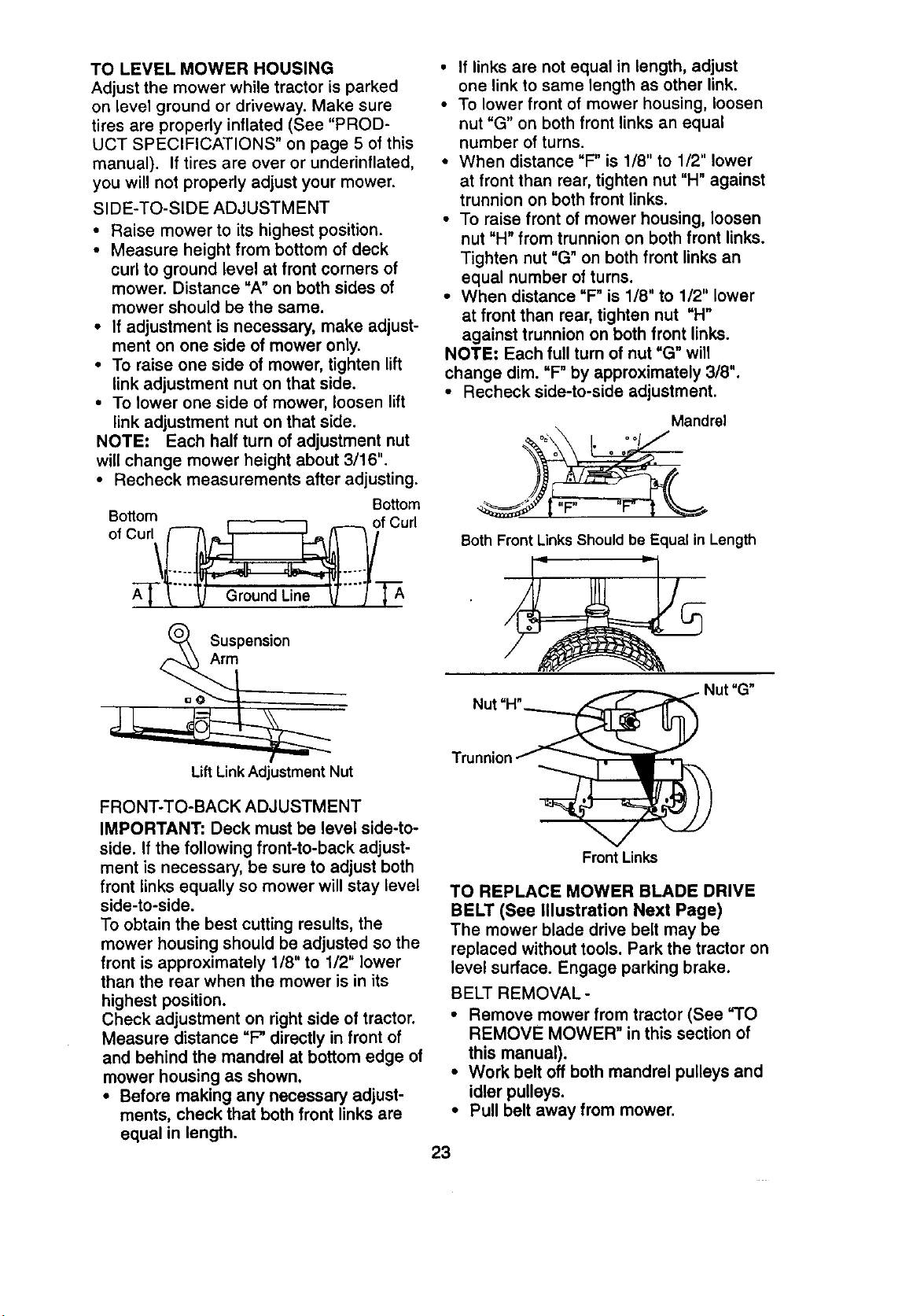
SIDE-TO-SIDE ADJUSTMENT
• Raise mower to its highest position.
• Measure height from bottom of deck
curl to ground level at front corners of
mower. Distance "A" on both sides of
mower should be the same.
• If adjustment is necessary, make adjust-
ment on one side of mower only.
• To raise one side of mower, tighten lift
link adjustment nut on that side.
• To lower one side of mower, loosen lift
link adjustment nut on that side.
NOTE: Each half turn of adjustment nut
will change mower height about 3/16".
• Recheck measurements after adjusting.
Bottom
Bottom
o,cur
Suspension
Arm
• If links are not equal in length, adjust
one link to same length as other link.
• To lower front of mower housing, loosen
nut "G" on both front links an equal
number of turns.
• When distance "F" is 1/8" to 1/2" lower
at front than rear, tighten nut "H" against
trunnion on both front links.
• To raise front of mower housing, loosen
nut "H" from trunnion on both front links.
Tighten nut "G" on both front links an
equal number of turns.
• When distance "F" is 1/8" to 1/2" lower
at front than rear, tighten nut "H"
against trunnion on both front links.
NOTE: Each full turn of nut =G" will
change dim. "F" by approximately 3/8".
• Recheck side-to-side adjustment.
Mandrel
Both Front LinksShouldbe Equal in Length
Nut =H",
LiftLinkAdjustment Nut
FRONT-TO-BACK ADJUSTMENT
IMPORTANT" Deck must be level side-to-
side. If the following front-to-back adjust-
ment is necessary, be sure to adjust both
front links equally so mower will stay level
side-to-side.
To obtain the best cutting results, the
mower housing should be adjusted so the
front is approximately 1/8" to 1/2" lower
than the rear when the mower is in its
highest position.
Check adjustment on right side of tractor.
Measure distance =F' directly in front of
and behind the mandrel at bottom edge of
mower housing as shown.
• Before making any necessary adjust-
ments, check that both front links are
equal in length.
Front Links
TO REPLACE MOWER BLADE DRIVE
BELT (See Illustration Next Page)
The mower blade drive belt may be
replaced without tools. Park the tractor on
level surface. Engage parking brake.
BELT REMOVAL-
• Remove mower from tractor (See "TO
REMOVE MOWER" in this section of
this manual).
• Work belt off both mandrel pulleys and
idler pulleys.
• Pull belt away from mower.
23
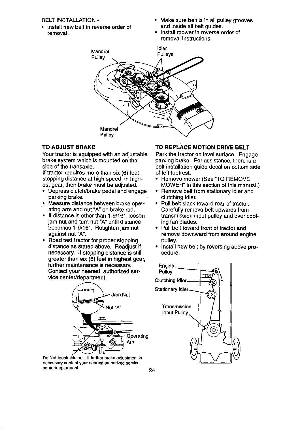
BELT INSTALLATION -
• install new belt in reverse order of
removal.
Mandrel
Pulley
• Make sure belt is in all pulley grooves
and inside all belt guides.
• install mower in reverse order of
removal instructions.
Idler
Pulleys
Mandrel
Pulley
TO ADJUST BRAKE
Your tractor is equipped with an adjustable
brake system which is mounted on the
side of the transaxle.
If tractor requires more than six (6) feet
stopping distance at high speed in high-
est gear, then brake must be adjusted.
• Depress clutch/brake pedal and engage
parking brake.
• Measure distance between brake oper-
ating arm and nut "A" on brake rod.
• If distance is other than 1-9/16", loosen
jam nut and turn nut "A" until distance
becomes 1-9/16". Retighten jam nut
against nut "A".
• Road test tractor for proper stopping
distance as stated above. Readjust if
necessary. If stopping distance is still
greater than six (6) feet in highest gear,
further maintenance is necessary.
Contact your nearest authorized ser-
vice center/department.
Jam Nut
Arm
Do Not touchthis nut, If furtherbrake adjustmentis
necessary contact your nearest authorized service
center/department
TO REPLACE MOTION DRIVE BELT
Park the tractor on level surface. Engage
parking brake. For assistance, there is a
belt installation guide decal on bottom side
of left footrest.
• Remove mower (See "TO REMOVE
MOWER" in this section of this manual.)
• Remove belt from stationary idler and
clutching idler.
• Pull belt slack toward rear of tractor.
Carefully remove belt upwards from
transmission input pulley and over cool-
ing fan blades.
• Pull belt toward front of tractor and
remove downward from around engine
pulley.
• install new belt by reversing above pro-
cedure.
Engine.._._......_
Pulley
Clutching Idler--
Stationary Idler-........
Transmission
Input Pulley _
24
TRANSMISSION REMOVAL/REPLACE-
MENT
Should your transmission require removal
for service or replacement, it should be
purged after reinstallation and before
operating the tractor. See "PURGE
TRANSMISSION" in the Operation section
of this manual.
TO ADJUST STEERING WHEEL ALIGN-
MENT
If steering wheel crossbars are not hori-
zontal (left to right) when wheels are posi-
tioned straight forward, remove steering
wheel and reassemble per instructions in
the Assembly section of this manual.
FRONT WHEEL TOE-IN/CAMBER
The front wheel toe-in and camber are not
adjustable on your tractor. If damage has
occurred to affect the front wheel toe-in or
camber, contact your nearest authorized
service center.
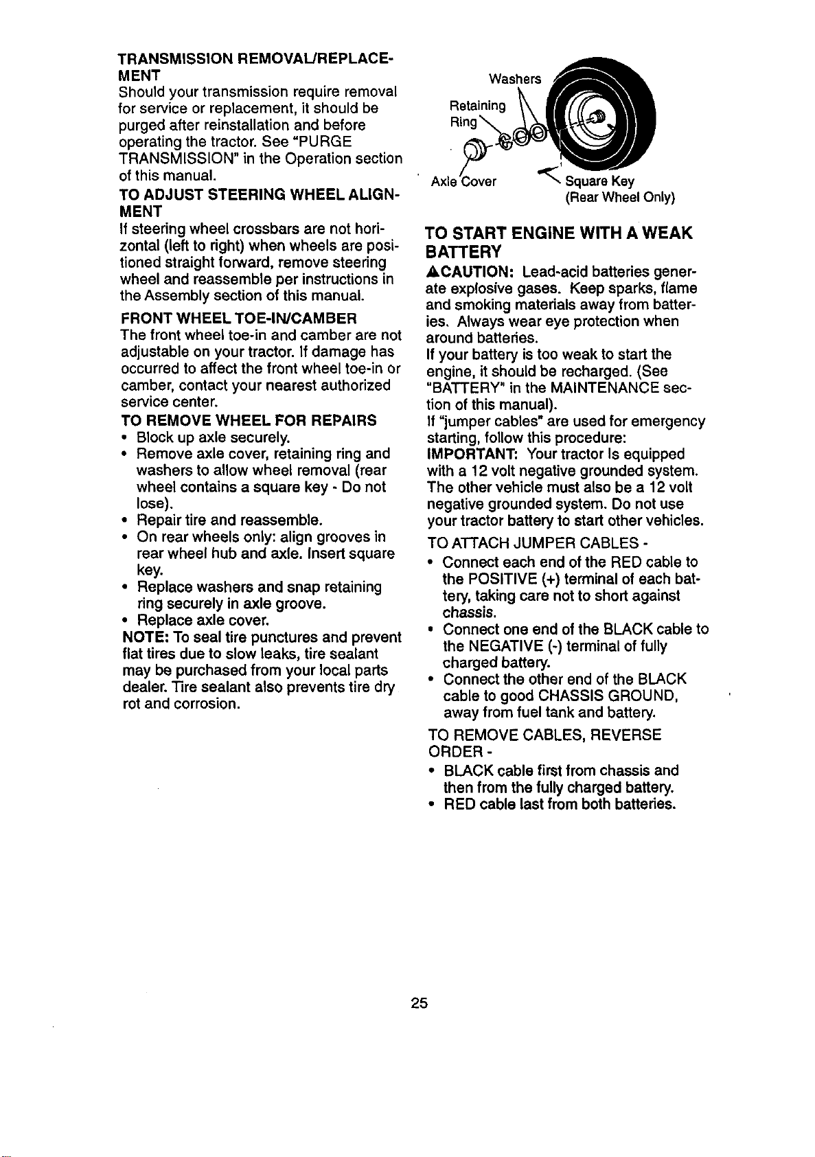
TO REMOVE WHEEL FOR REPAIRS
• Block up axle securely.
• Remove axle cover, retaining ring and
washers to allow wheel removal (rear
wheel contains a square key - Do not
lose).
• Repair tire and reassemble.
• On rear wheels only: align grooves in
rear wheel hub and axle. Insert square
key.
• Replace washers and snap retaining
ring securely in axle groove.
• Replace axle cover.
NOTE: To seal tire punctures and prevent
flat tires due to slow leaks, tire sealant
may be purchased from your local parts
dealer. Tire sealant also prevents tire dry
rot and corrosion.
Washers
Retaining
_' Square Key
(Rear Wheel Only)
TO START ENGINE WITH A WEAK
BATTERY
ACAUTION: Lead-acid batteries gener-
ate explosive gases. Keep sparks, flame
and smoking materials away from batter-
ies. Always wear eye protection when
around batteries.
If your battery is too weak to start the
engine, it should be recharged. (See
"BATTERY" in the MAINTENANCE sec-
tion of this manual).
If "jumper cables" are used for emergency
starting, follow this procedure:
IMPORTANT: Your tractor Is equipped
with a 12 volt negative grounded system.
The other vehicle must also be a 12 volt
negative grounded system. Do not use
your tractor battery to start other vehicles.
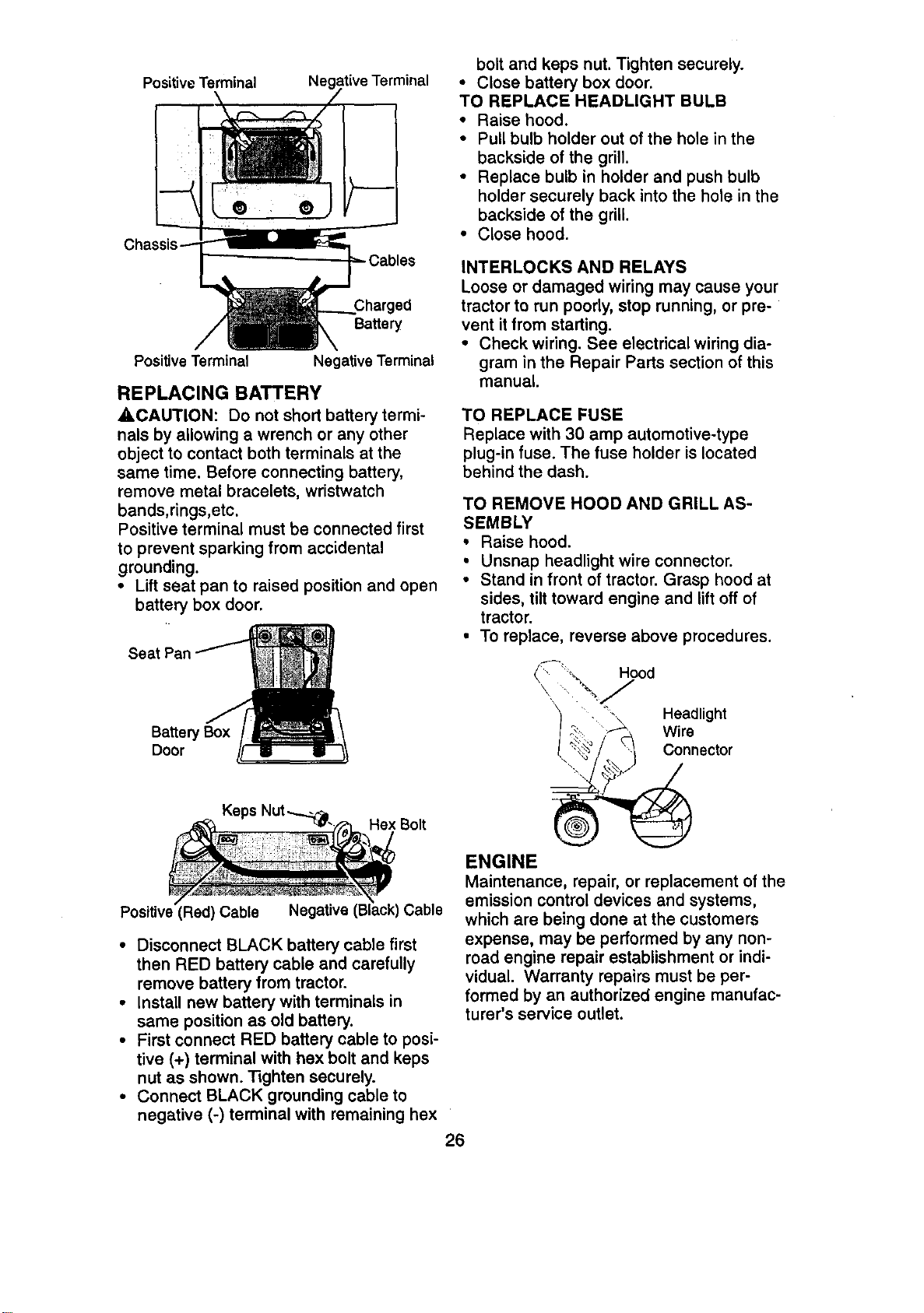
TO ATTACH JUMPER CABLES -
• Connect each end of the RED cable to
the POSITIVE (+) terminal of each bat-
tery, taking care not to short against
chassis.
• Connect one end of the BLACK cable to
the NEGATIVE (-) terminal of fully
charged battery.
• Connect the other end of the BLACK
cable to good CHASSIS GROUND,
away from fuel tank and battery.
TO REMOVE CABLES, REVERSE
ORDER -
• BLACK cable first from chassis and
then from the fully charged battery.
• RED cable last from both batteries.
25
Positive Terminal
Negative Terminal
bolt and keps nut. Tighten securely.
• Close battery box door.
TO REPLACE HEADLIGHT BULB
• Raise hood.
• Pull bulb holder out of the hole in the
backside of the grill.
• Replace bulb in holder and push bulb
holder securely back into the hole in the
backside of the grill.
• Close hood.
Charged
Battery
Positive Terminal Negative Terminal
REPLACING BATTERY
A, CAUTION: Do not short battery termi-
nals by allowing a wrench or any other
object to contact both terminals at the
same time. Before connecting battery,
remove metal bracelets, wristwatch
bands,rings,etc.
Positive terminal must be connected first
to prevent sparking from accidental
grounding.
• Lift seat pan to raised position and open
battery box door.
Seat
Battery Box
Door
Keps
Hex Bolt
Positive (Red) Cable
Cable
• Disconnect BLACK battery cable first
then RED battery cable and carefully
remove battery from tractor.
• install new battery with terminals in
same position as old battery,
• First connect RED battery cable to posi-
tive (+) terminal with hex bolt and keps
nut as shown. Tighten securely.
• Connect BLACK grounding cable to
negative (-) terminal with remaining hex
26
INTERLOCKS AND RELAYS
Loose or damaged wiring may cause your
tractor to run poorly, stop running, or pre-
vent it from starting.
• Check wiring. See electrical wiring dia-
gram in the Repair Parts section of this
manual.
TO REPLACE FUSE
Replace with 30 amp automotive-type
plug-in fuse. The fuse holder is located
behind the dash.
TO REMOVE HOOD AND GRILL AS-
SEMBLY
• Raise hood.
• Unsnap headlight wire connector.
• Stand in front of tractor. Grasp hood at
sides, tilt toward engine and lift off of
tractor.
. To replace, reverse above procedures.
_',"_'-_',, Hood
• -\ Headlight
_', Wire
_/_ q Connector
. I_I /
ENGINE
Maintenance, repair, or replacement of the
emission control devices and systems,
which are being done at the customers
expense, may be performed by any non-
road engine repair establishment or indi-
vidual. Warranty repairs must be per-
formed by an authorized engine manufac-
turer's service outlet.
TOADJUSTTHROTTLECONTROL
CABLE
Thethrottlecontrolhasbeenpresetatthe
factoryandadjustment should not be nec-
essary. Check adjustment as described
below before loosening cable. If adjust-
ment is necessary, proceed as follows:
• With engine not running, move throttle
control lever from slow to choke posi-
tion. Slowly move lever from choke to
fast position.
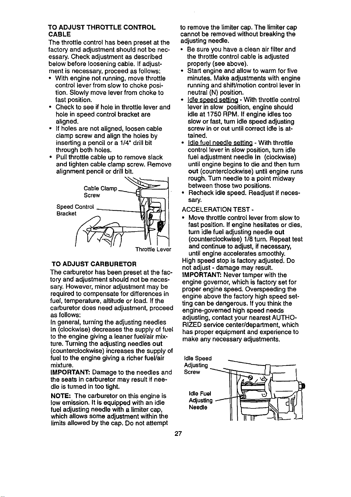
• Check to see if hole in throttle lever and
hole in speed control bracket are
aligned.
• If holes are not aligned, loosen cable
clamp screw and align the holes by
inseding a pencil or a 1/4" drill bit
through both holes.
• Pull throttle cable up to remove slack
and tighten cable clamp screw. Remove
alignment pencil or drill bit.
Cable Clamp...........__
Screw
SpecedeControl _'_.]_
Throttle Lever
TO ADJUST CARBURETOR
The carburetor has been preset at the fac-
tory and adjustment should not be neces-
sary. However, minor adjustment may be
required to compensate for differences in
fuel, temperature, altitude or load. If the
carburetor does need adjustment, proceed
as follows:
In general, turning the adjusting needles
in (clockwise) decreases the supply of fuel
to the engine giving a leaner fuel/air mix-
ture. Turning the adjusting needles out
(counterclockwise) increases the supply of
fuel to the engine giving a richer fuel/air
mixture.
IMPORTANT: Damage to the needles and
the seats in carburetor may result if nee-
dle is turned in too tight.
NOTE: The carburetor on this engine is
low emission. It is equipped with an idle
fuel adjusting needle with a limiter cap,
which allows some adjustment within the
limits allowed by the cap. Do not attempt
to remove the limiter cap. The limiter cap
cannot be removed without breaking the
adjusting needle.
• Be sure you have a clean air filter and
the throttle control cable is adjusted
properly (see above).
• Stad engine and allow to warm for five
minutes. Make adjustments with engine
running and shift/motion control lever in
neutral (N) position.
• Idle speed setting - With throttle control
lever in slow position, engine should
idle at 1750 RPM. If engine idles too
slow or fast, turn idle speed adjusting
screw in or out until correct idle is at-
tained.
• Idle fuel needl_ setting - With throttle
control lever in slow position, turn idle
fuel adjustment needle in (clockwise)
until engine begins to die and then turn
out (counterclockwise) until engine runs
rough. Turn needle to a point midway
between those two positions.
• Recheck idle speed. Readjust if neces-
sary.
ACCELERATION TEST -
• Move throttle control lever from slow to
fast position. If engine hesitates or dies,
turn idle fuel adjusting needle out
(counterclockwise) 1/8 turn, Repeat test
and continue to adjust, if necessary,
until engine accelerates smoothly.
High speed stop is factory adjusted. Do
not adjust - damage may result.
IMPORTANT: Never tamper with the
engine governor, which is factory set for
proper engine speed. Overspeeding the
engine above the factory high speed set-
ting can be dangerous. If you think the
engine-governed high speed needs
adjusting, contact your nearest AUTHO-
RIZED service center/depadment, which
has proper equipment and experience to
make any necessary adjustments.
Idle Speed
Adjusting
Screw
Idle Fuel
Adjusting
Needle
27
Immediatelyprepareyourtractorfor stor-
age at the end of the season or if the trac-
tor will not be used for 30 days or more.
_CAUTION: Never store the tractor with
gasoline in the tank inside a building
where fumes may reach an open flame or
spark. Allow the engine to cool before stor-
ing in any enclosure.
TRACTOR
Remove mower from tractor for winter
storage. This will allow you to clean it thor-
oughly. Remove all dirt, grease, leaves,
etc. Store in a clean, dry area.
• Clean entire tractor (See "CLEANING" in
the Maintenance section of this manual).
• Inspect and replace belts, if necessary
(See belt replacement instructions in the
Service and Adjustments section of this
manual).
• Lubricate as shown in the Maintenance
section of this manual.
• Be sure that all nuts, bolts and screws
are securely fastened. Inspect moving
parts for damage, breakage and wear,
Replace if necessary.
• Touch up all rusted or chipped paint sur-
faces; sand lightly before painting.
BATTERY
• Fully charge the battery for storage.
• After a period of time in storage, battery
may require recharging.
• To help prevent corrosion and power
leakage during long periods of storage,
battery cables should be disconnected
and battery cleaned thoroughly (see "TO
CLEAN BATTERY AND TERMINALS" in
the Maintenance section of this manual).
• After cleaning, leave cables disconnect-
ed and place cables where they cannot
come in contact with battery terminals.
• If battery is removed from tractor for
storage, do not store battery directly on
concrete or damp surfaces.
ENGINE
FUEL SYSTEM
IMPORTANT: It is important to prevent
gum deposits from forming in essential fuel
system parts such as carburetor, fuel filter,
fuel hose, or tank during storage. Also,
experience indicates that alcohol blended
fuels (called gasohol or using ethanol or
methanol) can attract moisture which leads
to separation and formation of acids during
storage. Acidic gas can damage the fuel
system of an engine while in storage.
• Drain the fuel tank.
• Start the engine and let it run until the
fuel lines and carburetor are empty.
• Never use engine or carburetor cleaner
products in the fuel tank or permanent
damage may occur.
• Use fresh fuel next season.
NOTE: Fuel stabilizer is an acceptable
alternative in minimizing the formation of
fuel gum deposits during storage. Add sta-
bilizer to gasoline in fuel tank or storage
container. Always follow the mix ratio
found on stabilizer container. Run engine
at least 10 minutes after adding stabilizer
to allow the stabilizer to reach the carbure-
tor. Do not drain the gas tank and carbure-
tor if using fuel stabilizer.
ENGINE OIL
Drain oil (with engine warm) and replace
with clean engine oil. (Sea "ENGINE" in
the Maintenance section of this manual).
CYLINDER(S)
• Remove spark plug(s).
• Pour one ounce of oil through spark plug
hole(s) into cylinder(s).
• Turn ignition key to =START" position for
a few seconds to distribute oil.
• Replace with new spark plug(s).
OTHER
• Do not store gasoline from one season
to another.
• Replace your gasoline can if it starts to
rust. Rust and/or dirt in your gasoline will
cause problems.
• If possible, store your tractor indoors
and cover it to give protection from dust
and dirt.
• Cover your tractor with a suitable protec-
tive cover that does not retain moisture.
Do not use plastic. Plastic cannot
breathe, which allows condensation to
form and cause your tractor to rust.
IMPORTANT: Never cover tractor while
engine and exhaust areas are still warm.
28
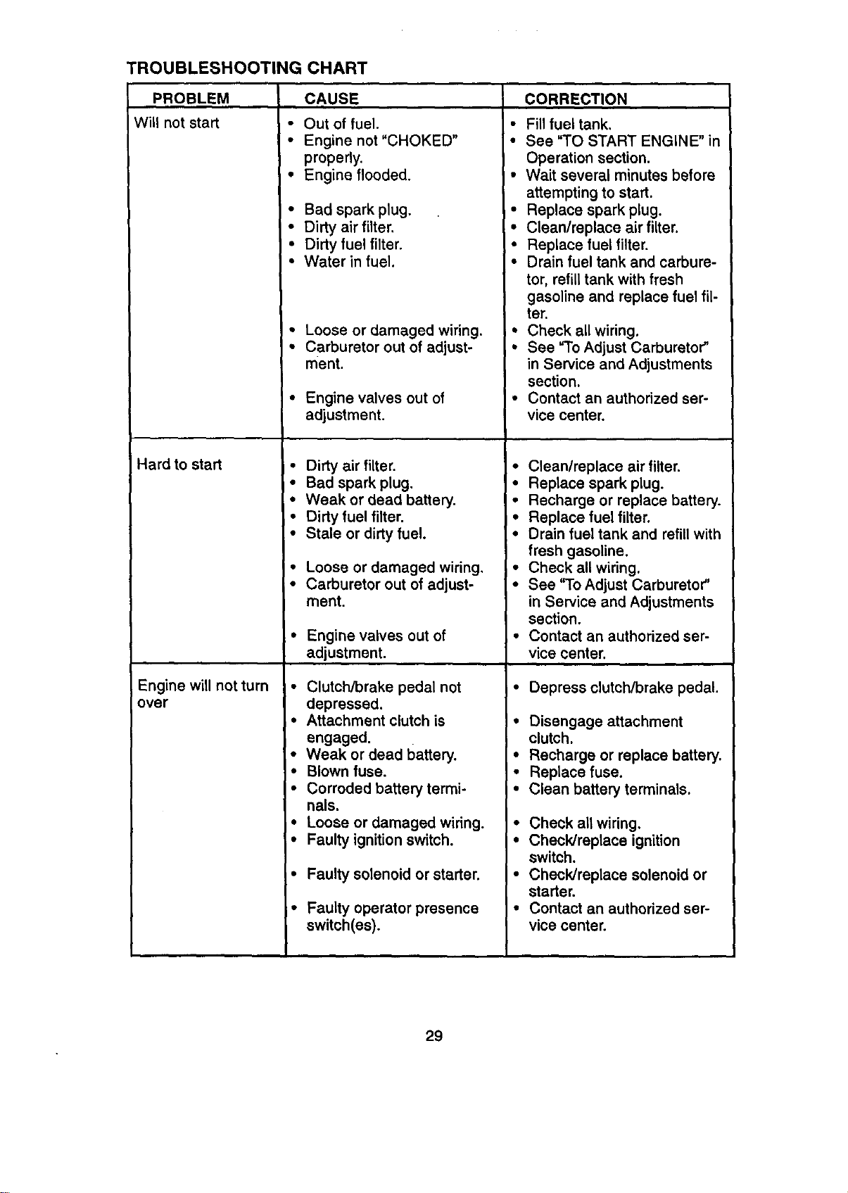
TROUBLESHOOTING CHART
PROBLEM
Will not start
Hard to start
Engine will not turn
over
i •
I •
CAUSE
Out of fuel.
Engine not "CHOKED" •
properly.
Engine flooded. •
Bad spark plug. •
Dirty air filter.
Dirty fuel filter. •
Water in fuel. •
Loose or damaged wiring. •
Carburetor out of adjust- •
ment.
Engine valves out of •
adjustment.
Dirty air filter. •
Bad spark plug. •
Weak or dead battery. •
Dirty fuel filter. *
Stale or dirty fuel. •
Loose or damaged wiring, •
Carburetor out of adjust- •
merit.
Engine valves out of
adjustment.
Clutch/brake pedal not i °
depressed.
Attachment clutch is I•
engaged,
Weak or dead battery. •
Blown fuse. I°
Corroded battery termi- I•
nals,
I
Loose or damaged wiring. I°
Faulty ignition switch. I•
I
Faulty solenoid or starter. I"
Faulty operator presence I°
switch(es).
CORRECTION
Fill fuel tank.
See "TO START ENGINE" in
Operation section.
Wait several minutes before
attempting to start.
Replace spark plug.
Clean/replace air filter.
Replace fuel filter.
Drain fuel tank and carbure-
tor, refill tank with fresh
gasoline and replace fuel fil-
ter.
Check all wiring.
See "To Adjust Carburetor"
in Service and Adjustments
section.
Contact an authorized ser-
vice center.
Clean/replace air filter.
Replace spark plug.
Recharge or replace battery.
Replace fuel filter.
Drain fuel tank and refill with
fresh gasoline.
Check all wiring.
See "To Adjust Carburetor"
in Service and Adjustments
section.
Contact an authorized ser-
vice center.
Depress clutch/brake pedal.
Disengage attachment
clutch.
Recharge or replace battery.
Replace fuse.
Clean battery terminals.
Check all wiring,
Check/replace ignition
switch.
Check/replace solenoid or
starter.
Contact an authorized ser-
vice center.
29
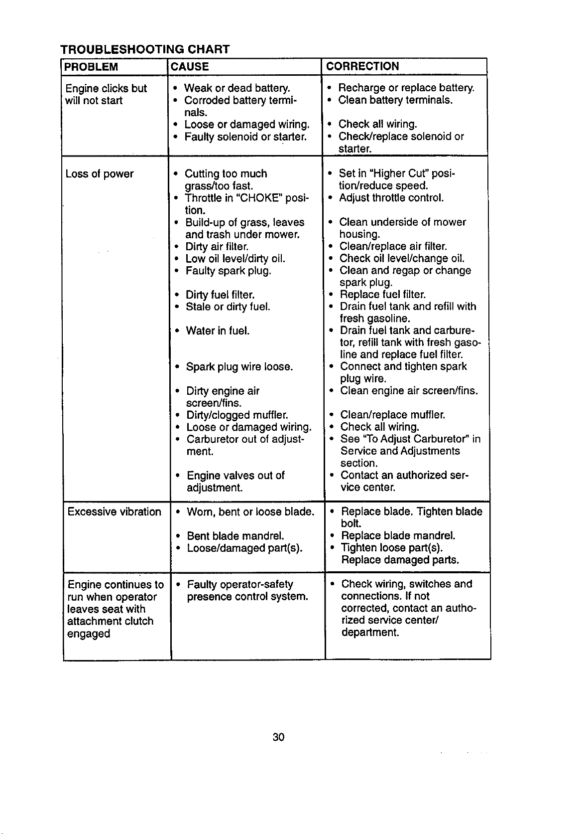
"ROUBLESHOOTING CHART
PROBLEM CAUSE CORRECTION
Engine clicks but • Weak or dead battery. • Recharge or replace battery.
will not start • Corroded battery termi- • Clean battery terminals.
nals.
• Loose or damaged wiring. * Check all wiring.
• Faulty solenoid or starter. • Check/replace solenoid or
starter.
Loss of power
Excessive vibration
Engine continues to
run when operator
leaves seat with
attachment clutch
engaged
• Cutting too much
grass/too fast.
• Throttle in "CHOKE" posi-
tion.
• Build-up of grass, leaves
and trash under mower.
• Dirty air filter.
• Low oil level/dirty oil.
• Faulty spark plug.
• Dirty fuel filter.
• Stale or dirty fuel.
• Water in fuel.
• Spark plug wire loose.
• Dirty engine air
screen/fins.
• Dirty/clogged muffler.
• Loose or damaged wiring.
• Carburetor out of adjust-
ment.
• Engine valves out of
adjustment.
• Worn, bent or loose blade.
• Bent blade mandrel.
• Loose/damaged part(s).
• Faulty operator-safety
presence control system.
• Set in "Higher Cut" posi-
tion/reduce speed.
• Adjust throttle control.
• Clean underside of mower
housing.
• Clean/replace air filter.
• Check oil level/change oil.
• Clean and regap or change
spark plug.
• Replace fuel filter.
• Drain fuel tank and refill with
fresh gasoline.
• Drain fuel tank and carbure-
tor, refill tank with fresh gaso-
line and replace fuel filter.
• Connect and tighten spark
plug wire.
• Clean engine air screen/fins.
• Clean/replace muffler.
• Check all wiring.
• See "To Adjust Carburetor" in
Service and Adjustments
section.
• Contact an authorized ser-
vice center.
• Replace blade. Tighten blade
bolt.
• Replace blade mandrel.
• Tighten loose part(s).
Replace damaged parts.
Check wiring, switches and
connections. If not
corrected, contact an autho-
rized service center/
department.
30
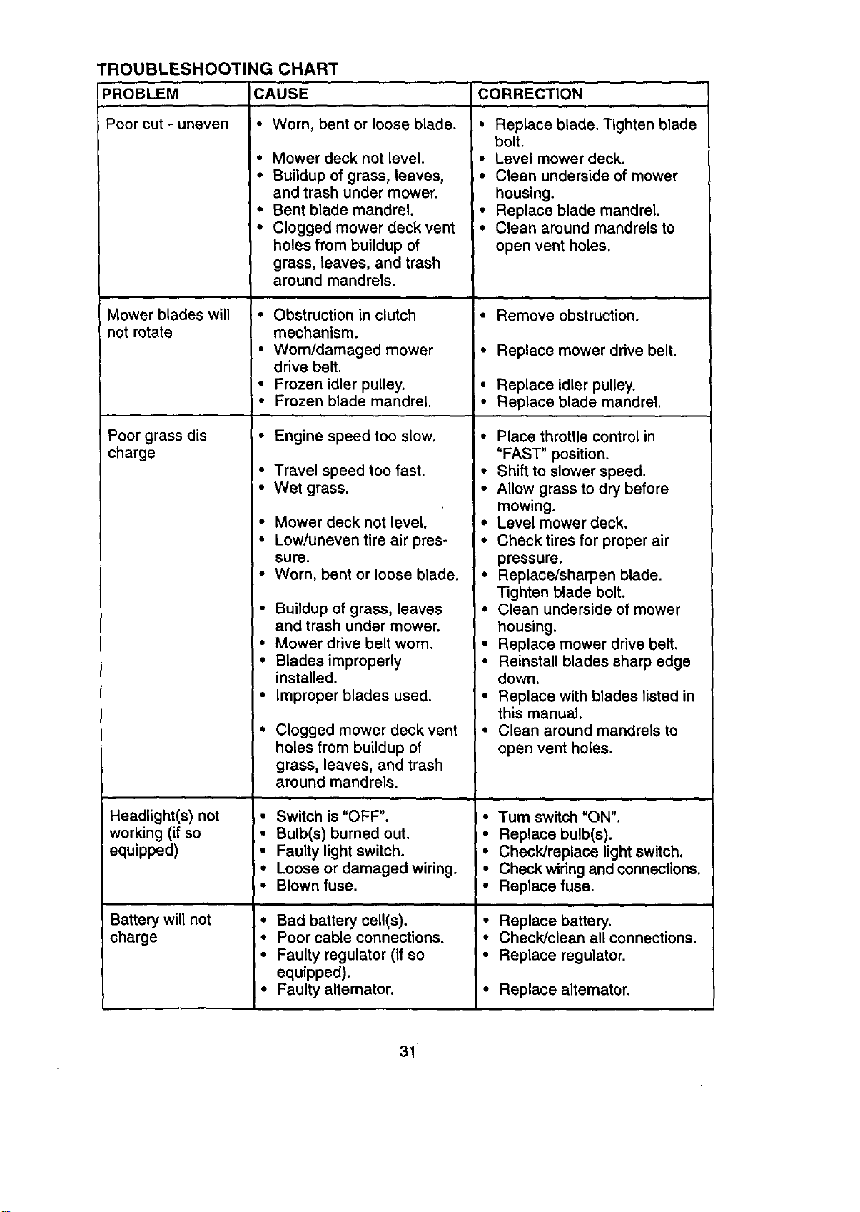
TROUBLESHOOTING CHART
PROBLEM
Poor cut - uneven
Mower blades will
notrotate
Poor grass dis
charge
Headlight(s) not
working (if so
equipped)
Battery will not
charge
CAUSE CORRECTION
• Worn, bent or loose blade.
• Mower deck not level.
• Buildup of grass, leaves,
and trash under mower.
• Bent blade mandrel.
• Clogged mower deck vent
holes from buildup of
grass, leaves, and trash
around mandrels.
• Obstruction in clutch
mechanism.
• Worn/damaged mower
drive belt.
• Frozen idler pulley.
• Frozen blade mandrel.
• Engine speed too slow.
• Travel speed too fast,
• Wet grass.
• Mower deck not level.
• Low/uneven tire air pres-
sure.
• Worn, bent or loose blade.
• Buildup of grass, leaves
and trash under mower.
• Mower drive belt worn.
• Blades improperly
installed.
• Improper blades used.
• Clogged mower deck vent
holes from buildup of
grass, leaves, and trash
around mandrels.
• Switch is "OFF".
• Bulb(s) burned out.
• Faulty light switch.
• Loose or damaged wiring.
• Blown fuse.
• Bad battery cell(s).
• Poor cable connections.
• Faulty regulator (if so
equipped).
• Faulty alternator.
• Replace blade. Tighten blade
bolt.
• Level mower deck.
• Clean underside of mower
housing.
I• Replace blade mandrel.
=• Clean around mandrels to
open vent holes.
• Remove obstruction.
• Replace mower drive belt.
• Replace idler pulley.
• Replace blade mandrel.
• Place throttle control in
"FAST" position.
• Shift to slower speed.
• Allow grass to dry before
mowing.
• Level mower deck.
• Check tires for proper air
pressure.
• Replace/sharpen blade.
Tighten blade bolt.
• Clean underside of mower
housing.
• Replace mower drive belt,
• Reinstall blades sharp edge
down.
• Replace with blades listed in
this manual.
• Clean around mandrels to
open vent holes.
• Turn switch "ON".
• Replace bulb(s).
• Check/replace light switch.
• Check wiring and connections.
• Replace fuse.
• Replace battery.
• Check/clean all connections.
• Replace regulator.
• Replace alternator.
31

TROUBLESHOOTING CHART
PROBLEM CAUSE
Loss of drive • Freewheel control in "dis-
engaged" position.
• Motion drive belt worn,
damaged or broken.
• Air trapped in transmis-
sion during shipment
or servicing.
I • u " n I •
: Eng ne backf res Engine throttle control not
when turning set at "SLOW"
engine "OFF" position for 30 seconds
before stopping engine.
CORRECTION
• Place freewheel control in
"engaged" position.
• Replace motion drive belt.
• Purge transmission,
• Move throttle control to
"SLOW" position and allow
to idle for 30 seconds before
stopping engine.
32
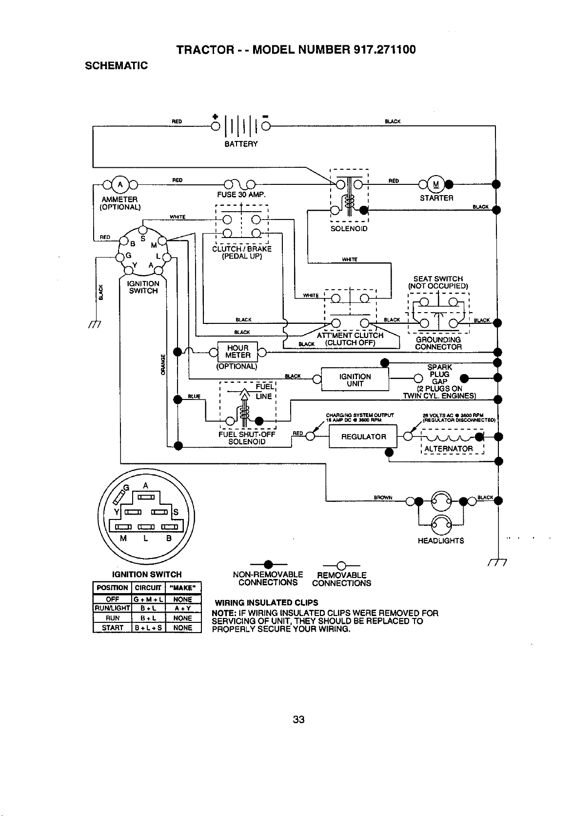
SCHEMATIC
TRACTOR - - MODEL NUMBER 917.271100
BATTERY
__ RE0
AMMETER FUSE 30 AMP,
(OPTIONAL) _ _
1 I
i I o
L ....... J
CLUTCH / BRAKE
_-_ _G LI (PEDAL UP)
IGNITION
SWITCH
I RED
_J_ll STARTER STACK
SOLENOID
SEATSWITCH
WHITE I........ I ,-'(NOTOCCUPIED)
BLACK
BLACK
LINE i
'_',.... J
FUEL SHUT-OFF
SOLENOID
IGNITION SWITCH
(CLUTCH OFF}
A
v SPARK
IGNITION / PLUG
UNIT _ GAP
J (2 PLUGS ON
TWIN CYL ENGINES)
CHARG_k_ SYSTEM OUTPUT _ VOLT8 _ • _ RPM
_lb I '1ALTERNATOR 1
BROWN
HEADLIGHTS
NON-REMOVABLE REMOVABLE
CONNECTIONS CONNECTIONS
WIRING INSULATED CLIPS
NOTE: IF WIRING INSULATED CLIPS WERE REMOVED FOR
SERVICING OF UNIT, THEY SHOULD BE REPLACED TO
PROPERLY SECURE YOUR WIRING.
33
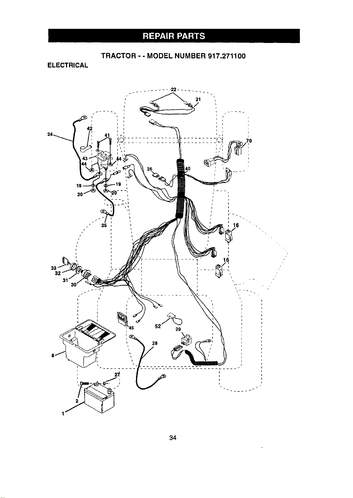
ELECTRICAL
TRACTOR - - MODEL NUMBER 917.271100
41
16
i
/
34
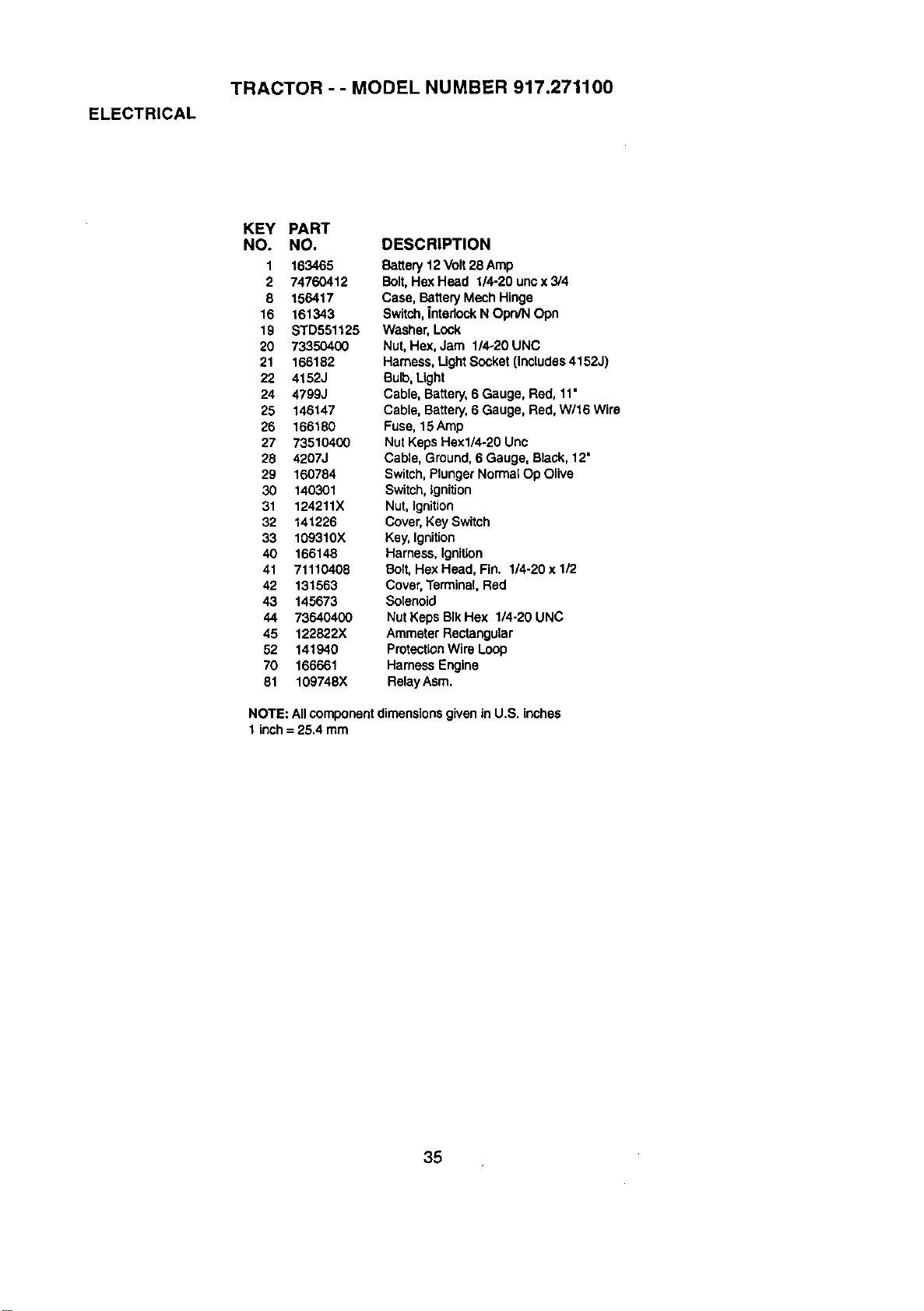
ELECTRICAL
TRACTOR - - MODEL NUMBER 917.271100
KEY PART
NO. NO.
1 163465
2 74760412
8 156417
16 161343
19 STD551125
20 73350400
21 166182
22 4152J
24 4799J
25 146147
26 166180
27 73510400
26 4207J
29 160784
30 140301
31 124211X
32 141226
33 109310X
40 166148
41 71110408
42 131563
43 145673
44 73640400
45 122822X
52 141940
70 166661
81 109748X
DESCRIPTION
Battery12Volt 28 Amp
Bolt,Hex Head 1/4-20 unc x 3/4
Case, Battery Mech Hinge
Switch,|ntadock N OPO/NOpn
Washer, Lock
Nut,Hex, Jam 1/4-20 UNC
Harness,LightSocket (Includes4152J)
Bulb,Light
Cable, Battery,6 Gauge, Red, 11"
Cable, Battery,6 Gauge, Red, W/16 Wire
Fuse, 15Amp
Nut Keps Hexl/4-20 Unc
Cable, Ground,6 Gauge, Black,12"
Switch,PlungerNormalOp Olive
Switch,Ignition
Nut,Ignition
Cover,Key Switch
Key, Ignition
Harness,Ignition
Bolt,Hex Head, Fin. 1/4-20 x 1/2
Cover,Terminal.Red
Solenoid
Nut Keps BIkHex 1/4-20 UNC
AmmeterRectangular
ProtectionWire Loop
Harness Engine
RelayAsrn.
NOTE: Allcomponentdimensions givenin U.S. inches
1 inch= 25.4 mm
35
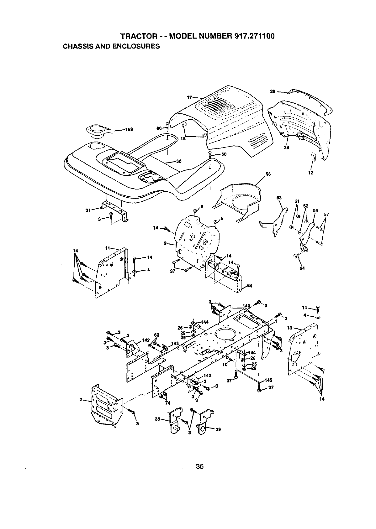
TRACTOR - - MODEL NUMBER 917.271100
CHASSIS AND ENCLOSURES
28
58
12
31
14 11
4
53
145
37
54
33
57
14
• 36
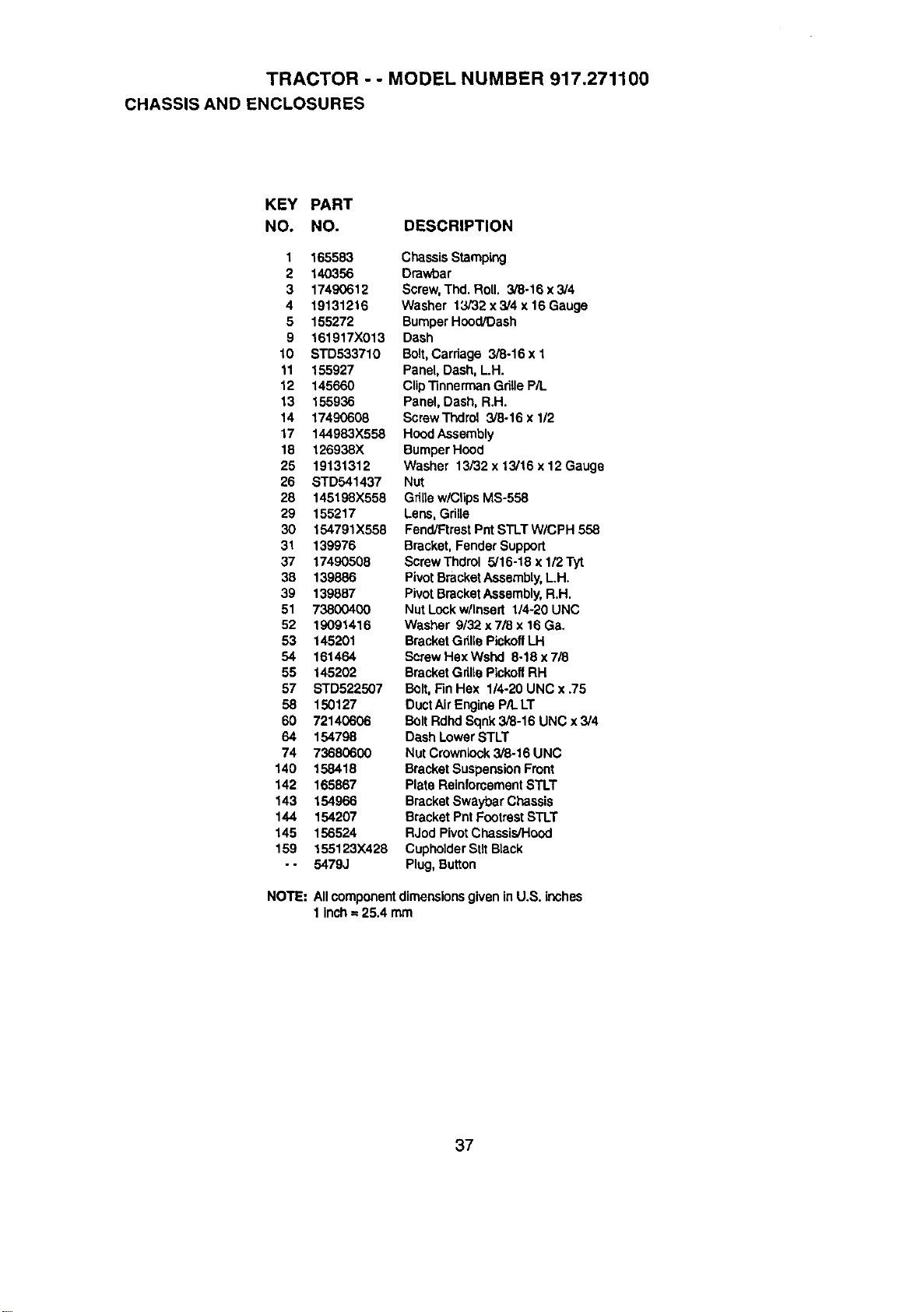
TRACTOR - - MODEL NUMBER 917.271100
CHASSIS AND ENCLOSURES
KEY PART
NO. NO. DESCRIPTION
1 165583
2 140356
3 17490612
4 19131216
5 155272
9 161917X013
10 STD533710
11 155927
12 145660
13 155936
14 17490608
17 144983X558
18 126938X
25 19131312
26 STD541437
28 145198X558
29 155217
30 154791X558
31 139976
37 17490508
38 139886
39 139887
51 73800400
52 19091416
53 145201
54 161464
55 145202
57 STD522507
58 150127
60 72140606
64 154798
74 73680600
140 158418
142 165867
143 154966
144 154207
145 156524
159 155123X428
- - 5479J
Chassis Stamping
Dmwbar
Screw, Thd. Roll. 3/8-16 x 3/4
Washer 13/32 x 3/4 x 16 Gauge
Bumper Hood/Dash
Dash
Bolt,Carriage 3/8-16 x 1
Panel,Dash, LH.
Clip TinnermanGdllePiL
Panel, Dash, R.H.
ScrewThdrol 3/8-16 x 1/2
HoodAssembly
BumperHood
Washer 13/32 x 13/16 x 12 Gauge
Nut
Grillew/ClipsMS-558
Lens, Grille
Fend/FtrestPnt STLT W/CPH 558
Bracket, FenderSupport
ScmwThdrol 5/16-18 x l/2Tyt
PivotBracketAssembly,L.H.
PivotBracketAssembly,R.H.
Nut Lockw/Insert 1/4-20 UNC
Washer 9/32 x7/8 x 16 Ga.
BracketGrinePickoffLH
ScrewHex Wshd 8-18 x 718
BracketGriltePlckoflRH
Bolt, Fin Hax 114-20UNC x .75
DuctAirEngine P/L LT
BoltRdhdSqnk3/8-16 UNC x 3/4
Dash Lower STLT
Nut Crownlock3/8-16 UNC
BracketSuspensionFront
Plate ReinforcementSTLT
BracketSwaybar Chassis
Bracket Pnt FootrestSTLT
RJod PivotChassis/Hood
CupholderStltBlack
Plug,Button
NOTE: Allcomponentdiroenslonsgiven inU.S. inches
1 inch= 25.4 taro
37
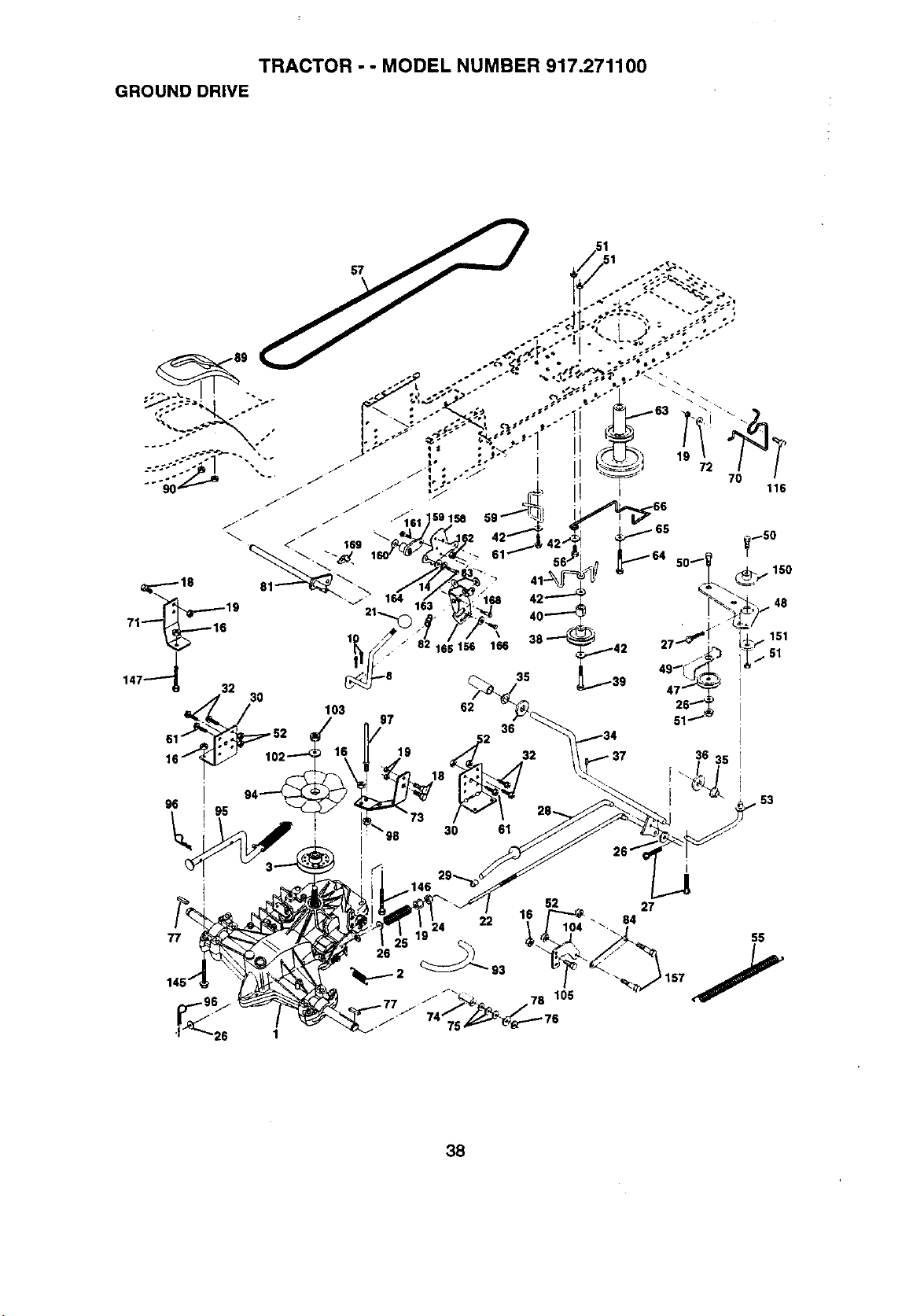
TRACTOR - - MODEL NUMBER 917.271100
GROUND DRIVE
52 27
22 104 _ 84
38
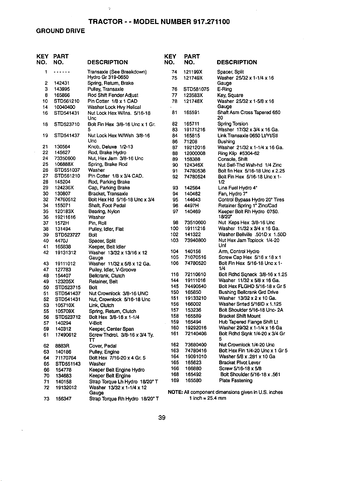
TRACTOR - - MODEL NUMBER 917.271100
GROUND DRIVE
KEY PART KEY PART
NO. NO. DESCRIPTION NO. NO.
1 Transaxle (See Breakdown) 74 121199X
HydroGr 319-0650 75 121749X
2 142431 Spdng, Return,Brake
3 143995 Pulley,Transaxle 76 STD581075
8 165866 RodShift FenderAdjust 77 123583X
10 STD561210 PinCotter 1/6 x 1 CAD 78 121748X
14 10040400 Washer LockHvy Helical
16 STD541431 NutLockHexW/Ins. 5/16-18 '81 165591
Unc
18 STD523710 BoltFin Hex 3/8-16 Unc x 1 Gr, 82 165711
5 83 19171216
19 STD541437 NutLockHexW/Wsh 3/8-16 84 165815
Uric 86 71208
21 130564 Knob,Deluxe 1/2-13 87 19212016
22 145627 Rod, Brake Hydro 88 12000008
24 73350600 Nut, HexJam 3/8-16 Unc 89 158388
25 106888X Spring,Brake Rod 90 124346X
26 STD551037 Washer 91 74780536
27 STD561210 PinCotter 1/8 x3/4CAD. 92 74780524
28 145204 Rod,Parking Brake
29 124236X Cap, Parking Brake 93 142564
30 130807 Bracket,Transaxle 94 140462
32 74760512 BoltHexHd 5/16-18Uncx3/4 95 144643
34 155071 Shaft, FootPedal 96 4497H
35 120193X Beadng,Nylon 97 140469
36 19211616 Washer
37 1572H Pin, Roll 98 73510600
38 131494 Pulley,idler, Flat 100 19111216
39 STD523727 Bolt 102 141322
40 4470J Spacer,Split 103 73940800
41 165838 Keeper, Belt Idler
42 19131312 Washer 13/32 x 13/16 x 12 104 140156
Gauge 105 71070516
43 19111012 Washer 11/32x 5/8x 12 Ga. 106 74780520
47 127783 PuLley,idler,V-Groove
48 154407 Bellcrank,Clutch 116 72110610
49 123205X Retainer, Belt 144 19111016
50 STD523715 Bolt 145 74490540
51 STD541437 NutCrownlook 3/8-16 UNC 150 165850
52 STD541431 Nut,Crownlock 5/16-18 Uns 151 19133210
53 105710)( Unk, Clutch 156 166002
55 105709X Spdng, Return, Clutch 157 153236
56 STD523712 Bolt Hex 3/8-16x 1-1/4 158 165589
57 140294 V-Belt 159 165494
59 140312 Keeper,CenterSpan 160 19292016
61 17490612 ScrewThdrol. 3/8-16x3/4Ty. 161 72140406
"rE
62 8883R Cover, Pedal 162 73680400
63 140186 Pulley,Engine 163 74780416
64 71170764 BoltHex 7/16-20x4Gr. 5 164 19091010
65 STD551143 Washer 165 165623
66 154778 Keeper Belt EngineHydro 166 166880
70 134683 Keeper Bolt Engine 168 165492
71 140158 StrapTorque Lh Hydro 18/20"T 169 165580
72 19132012 Washer 13/32x 1-1/4 x 12
Gauge
73 156347 StrapTorqueRh Hydro 18/20"T
DESCRIPTION
Spacer,Split
Washer 25/32 x 1-1/4 x 16
Gauge
E-Ring
Key,Square
Washer 25/32 x 1-5/8 x 16
Gauge
ShaftAsm CrossTapered650
20
SpdngTorsion
Washer 17/32 x 3/4 x 16Ga.
LinkTransaxle 0650 Lt/Yt/Stl
Bushing
Washer 21/32 x 1-1/4 x 16 Ga.
RingKlip #5304-62
Console, Shift
Nut Self-Thd Wsh-hd 1/4 Zinc
Bolt fin Hex 5/16-18 Unc x 2.25
Bolt Fin Hex 5/16-18 Unex 1-
1/2
Line Fuel Hydro 4"
Fan, Hydro 7"
Control Bypass Hydro 20"Tires
Retainer Spdng 1• Zinc/Ced
Keeper Bolt Rh Hydro 0750.
18/20"
Nut Keps Hex 3/8-16 Unc
Washer 11/32 x 3/4 x 16 Ga.
WasherBellvUle .501D x 1.50D
Nut Hex Jam Toptock 1/4-20
Unf
Arm, Control Hydro
ScrewCap Hex 5/16 x 18 x 1
Bolt Fin Hex 5/16-18 Unc x 1-
1/4
Bolt Rdhd Sqneck 3/8-16 x 1.25
Washer 11/32x 5/8 x 16 Ga.
Bolt Hex FLGHD 5/16-18 x Gr 5
Bushing Bollerank Grd Ddve
Washer 13/32 x 2 x 10 Ga.
Washer Srrted5/161Dx 1.125
Bolt Shoulder5/16-18 Unc- 2A
Bracket ShiftMount
Hub Tapered Range Shift Lt
Washer 29/32 x 1-1/4 x 16 Ga
Bolt Rdhd Sqnk 1/4-20 x 3/4 Gr
5
Nut Crownlock 1/4-20 Uric
Bolt Hex Fin 114-20Unc x 1Gr5
Washer 5/8 x .281 x 10 Ga
Bracket PivotLever
Screw5/16-18 x 5/8
Bolt Shoulder5/16-18 x .561
Plate Fastening
NOTE: Allcomponentdimensionsgiven in U.S. inches
1 inch= 25.4 mm
39

TRACTOR - - MODEL NUMBER 917.271100
STEERING ASSEMBLY
"'-"'---38
..::_----.---;°°
;,-----'--42
t_ . o •
62 44
le
11
27
, 2
47
6s
67
4O

TRACTOR - - MODEL NUMBER 917.271100
STEERING ASSEMBLY
KEY PART
NO. NO. DESCRIPTION
1 139768
2 154427
3 156483
4 157473
5 6266H
6 121748X
7 19272016
8 12000029
9 3366R
10 156438
11 STD551137
13 154779
15 73901000
17 156546
18 57079
19 160395
22 165857
23 165851
25 154406
26 126847X
27 136874
28 19131416
29 17490612
30 STD561210
32 130465
36 155099
37 152927
38 139769
39 19133808
40 STD541537
41 100711L
42 145054
43 121749X
44 153720
46 121232X
47 6855M
51 STD541431
54 74780520
62 156594
63 STD523710
65 154780
66 154404
67 74781044
68 154429
79 19132012
80 74950612
SteeringWheel
AxleAssemblySTMP DroppedSTL
SpindleAssembly,L.H.
SpindleAssembly,R.H.
Baadng,Race, Thrust,Hardened
Washer 25/32 x 1-5/8 x 16 Gauge
Washer 27/32 x 1-1/4 x16 Gauge
Ring,Klip
Beadng,SteenngColumn
DraglinkExtendedStamped
Washer, Lock
Beadng Axle STLT/GT
Nut, Lock, Flange 5/8-11 UNC
Shaft Assembly, Steering
Washer, Thrust .515 x .750 x .033
Support, Shaft
Screw Hex Wshhd Torx
Pittman Shaft Assembly
Bracket, Steering
Bushing, Link, Drag
Gear, Sector
Washer 13i32 x 7/8 x 16 Gauge
Screw,Thd., Roll. 3/8-16 x 3/4
Pin
Rod, "Re
Bushing, Steedno
Screw
Insert, Steedng Wheet
Washer 13/32 x 2-3/8 x 8 Gauge
Gdp¢o Nut
Adaptor, Steering Wheel
Boot,SteedngShaft
Washer 25/32 x 1-1/4 x 16 Gauge
Extension Shaft Steedng LR.LT
Cap, Spindle
Fitting, Grease
Nut Lock Hex w/Ins. 5/16-18 UNC
Bolt Fin Hax 5/16-18 UNC x 1.1/4
KitSteedng Asm Service
Bolt, Fin Hex 3/8-16 UNC x 1 Gr 5
Spacer AXle
BeadngArm Pittman
Bolt,Fin Hex 5/8-11 UNC x 2-3/4
Axle, Brace
Washer 13/32 x 1-1/4 x 12 Ga
Bolt Hex Nylon 3/8-16 x 3/4
NOTE: Allcomponentdimensionsgivenin U.S. inches
1 inch= 25.4 mm
41
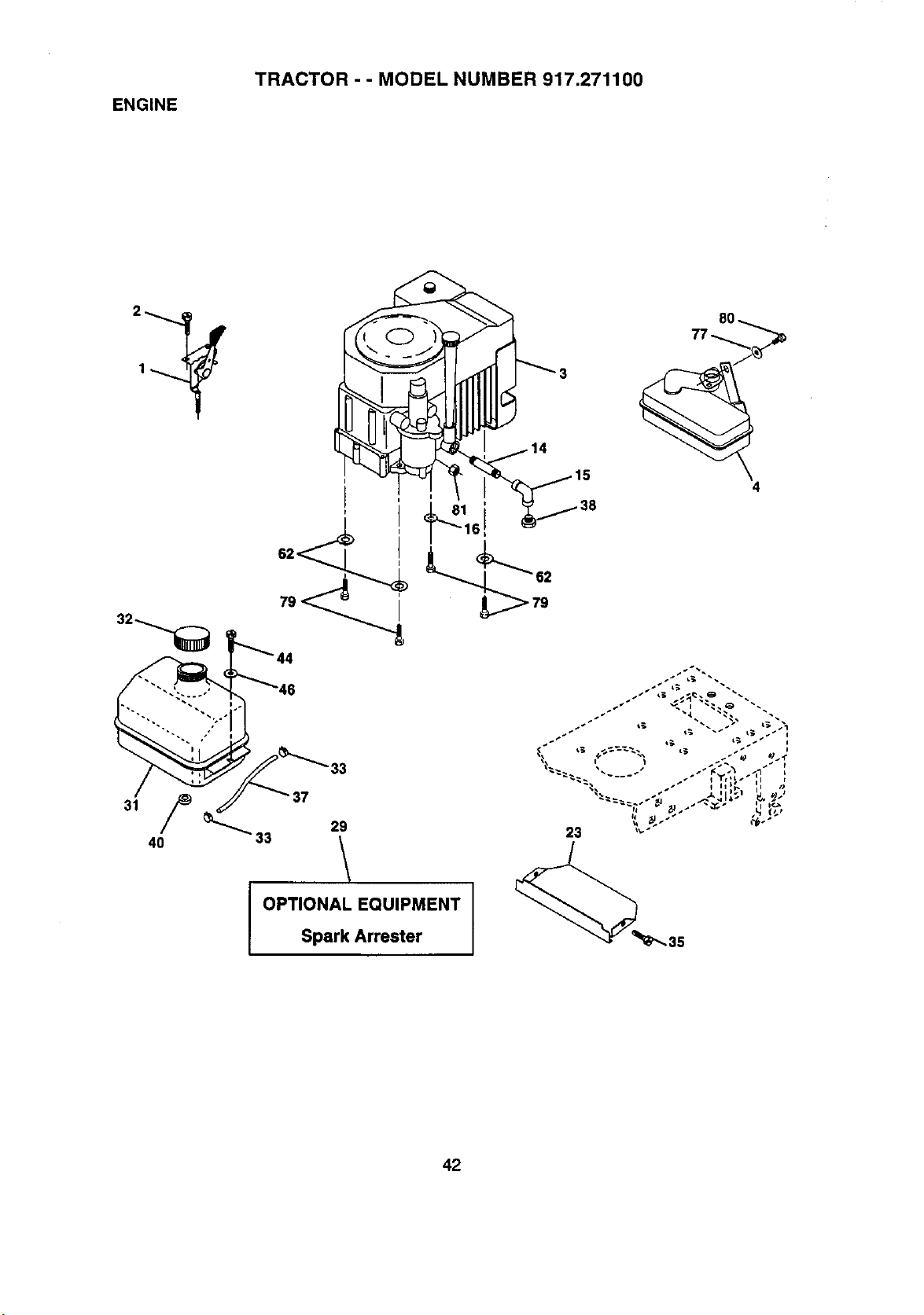
ENGINE
TRACTOR - - MODEL NUMBER 917.271100
40
33
29
\
J OPTIONAL EQUIPMENT
Spark Arrester
4
sI _ _ r;_:_
s _ _j. _
s_ _ - _ _ L_,
23 """
42
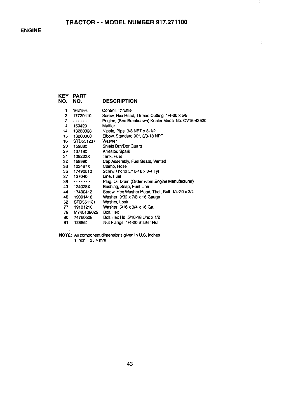
ENGINE
TRACTOR - - MODEL NUMBER 917.271100
KEY PART
NO. NO. DESCRIPTION
1 162156
2 17720410
3 ......
4 159420
14 13280328
15 13200300
16 STD551237
23 159880
29 137180
31 109202X
32 158990
33 123487X
35 17490512
37 137040
38 .......
40 124028X
44 17490412
46 19091416
62 STD551131
77 19101216
79 M740108025
80 74760508
81 128861
Control,Throttle
Screw, Hex Head, Thread Cutting 1/4-20 x 5/8
Engine,(See Breakdown)KohlerModel No. CV16-43520
Muffler
Nipple,Pipe 3/8 NPT x 3-1/2
Elbow,Standard90°, 3/8-18 NPT
Washer
ShieldBrn/DbrGuard
Arrestor,Spad_
Tank, Fuel
Cap Assembly,Fuel Sears, Vented
Clamp, Hose
Screw Thdrol5/16-18 x 3-4 Tyt
Line,Fuel
Plug,OilDrain (Order From EngineManufacturer)
Bushing,Snap, Fuel Line
Screw,Hex Washer Head, Thd., Roll. 1/4-20 x 3/4
Washer 9/32 x 7/8 x16 Gauge
Washer, Lock
Washer 5/16 x 3/4 x 16 Ga.
BoltHex
BoltHex Hd 6/16-18 Unc x 1/2
Nut Flange 1/4-20 StarterNut
NOTE: All componentdimensionsgivenin U.S. inches
1inch = 25.4 mm
43
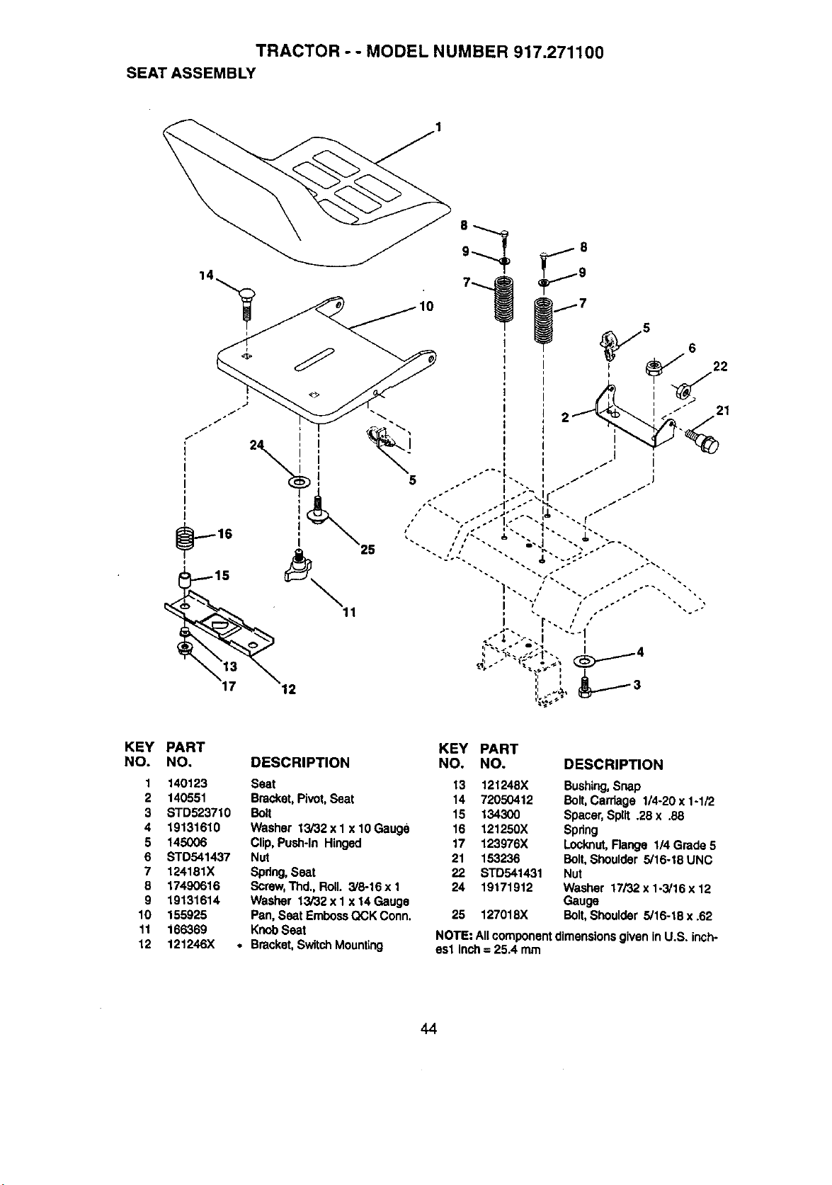
TRACTOR - - MODEL NUMBER 917.271100
SEAT ASSEMBLY
10
KEY PART
NO. NO.
1 140123
2 140551
3 STD523710
4 19131610
5 145006
6 STD541437
7 124181X
8 17490616
9 19131614
10 155925
11 166369
12 121246X
KEY PART
DESCRIPTION NO. NO. DESCRIPTION
Seat 13 121248X
Bracket,Pivot,Seat 14 72050412
Bolt 15 134300
Washer 13/32 x 1 x 10 Gauge 16 121250X
Clip, Push-In Hinged 17 123976X
Nut 21 153236
Spdng,Seat 22 STD541431
Screw,Thd., Roll. 3/8-16 x 1 24 19171912
Washer 13/32 x 1 x 14 Gauge
Pan, Seat EmbossQCK Conn. 25 127018X
KnobSeat
• Bracket,SwitchMounting
Bushing,Snap
Bolt, Carriage 1/4-20 x 1-1/2
Spacer,Split .28 x .88
Spring
Locknut,Range 114Grade 5
Bolt,Shoulder 5/16-18 UNC
Nut
Washer 17/32 x 1-3/16 x 12
Gauge
Bolt, Shoulder 5/16-18 x .62
NOTE: All component dimensionsgiven in U.S. inch-
esl inch= 25.4 mm
44
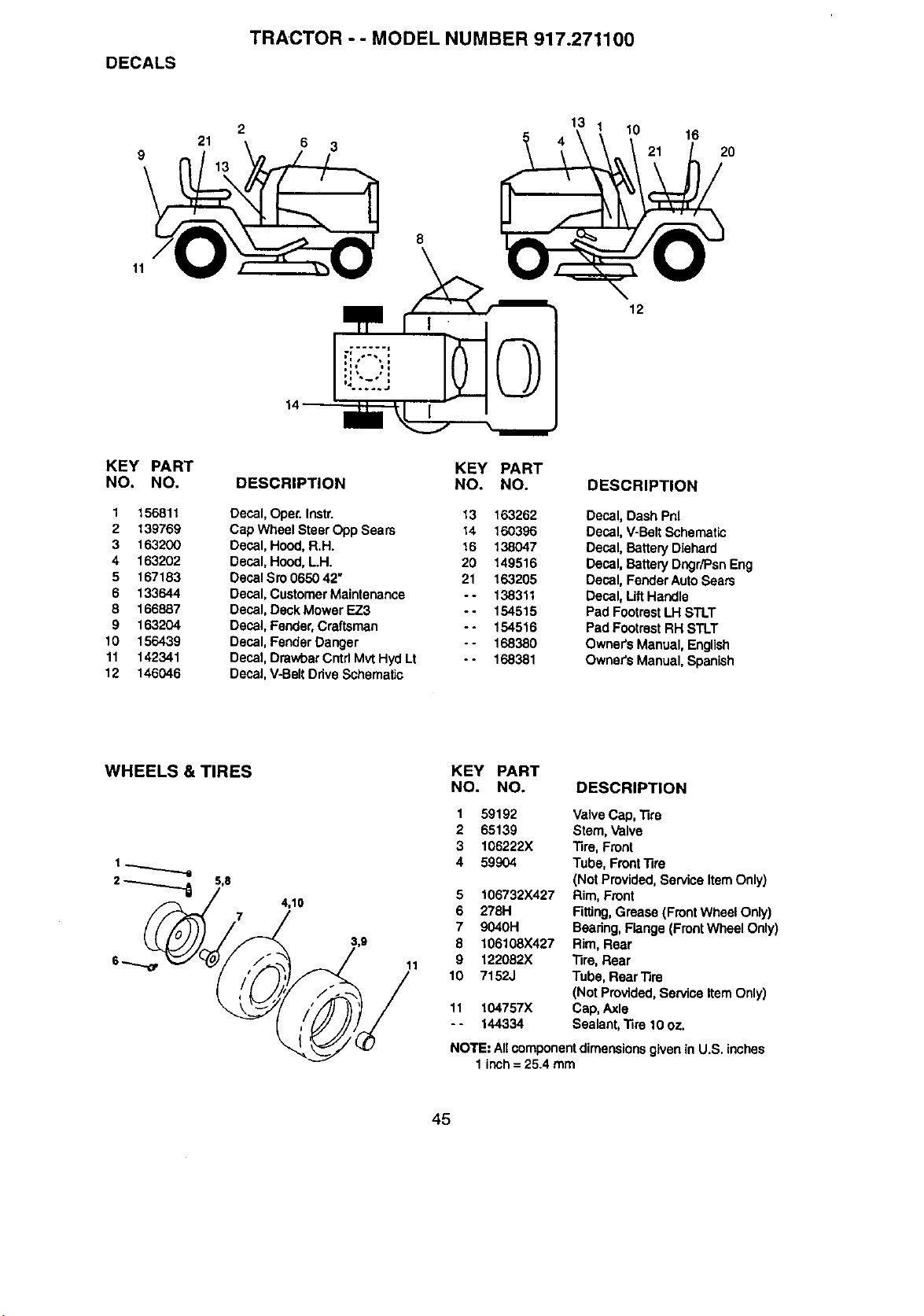
DECALS
TRACTOR -- MODEL NUMBER 917.271100
2
21
6 3
13
10
16
20
11
KEY PART
NO. NO.
1 156811
2 139769
3 163200
4 163202
5 167183
6 133644
8 166887
9 163204
10 156439
11 142341
12 146046
14'
8
DESCRIPTION
KEY PART
NO. NO.
Decal, Oper.Instr.
Cap Wheel Steer Opp Sears
Decal, Hood,R.H.
Decal, Hood,L.H.
Decal Sro 0650 42"
Decal,Customer Maintenance
Decal, DeckMower EZ3
Decal, Fender,Craftsman
Decal, FenderDanger
Decal, DrawbarCntd MvtHyciLt
Decal,V-Belt DriveSchematic
13 163262
14 16O396
16 138047
20 149516
21 163205
- - 138311
- - 154515
- - 154516
- - 168380
- - 168381
12
DESCRIPTION
Decal, Dash Pnl
Decal, V-Belt Schematic
Decal, Battery Diehard
Decal, Battery Dngr_sn Eng
Decal, FenderAuto Sears
Decal, LiftHandle
Pad FootrestLH STLT
Pad Footrest RH STLT
Owner's Manual, English
Owner's Manual, Spanish
WHEELS & TIRES
4,10
11
KEY PART
NO. NO. DESCRIPTION
1
2
3
4
5
6
7
8
9
10
11
..
59192 Valve Cap, "lire
65139 Stem, Valve
106222X Tire, Front
59904 Tube, Front"fire
(Not Provided,Service Item Only)
106732X427 Rim, Front
278H Fitting,Grease (FrontWheel Only)
9040H Beadng,Flange (FrontWheel Only)
106108X427 Rim, Rear
122082X Tire, Rear
7152J Tube, Rear Tire
(Not Provided,Service ItemOnly)
104757X Cap, Axle
144334 Sealant,"fire 10 oz.
NOTE: AIIcomponentdimensionsgivenin U.S. inches
1 inch= 25.4 mm
45
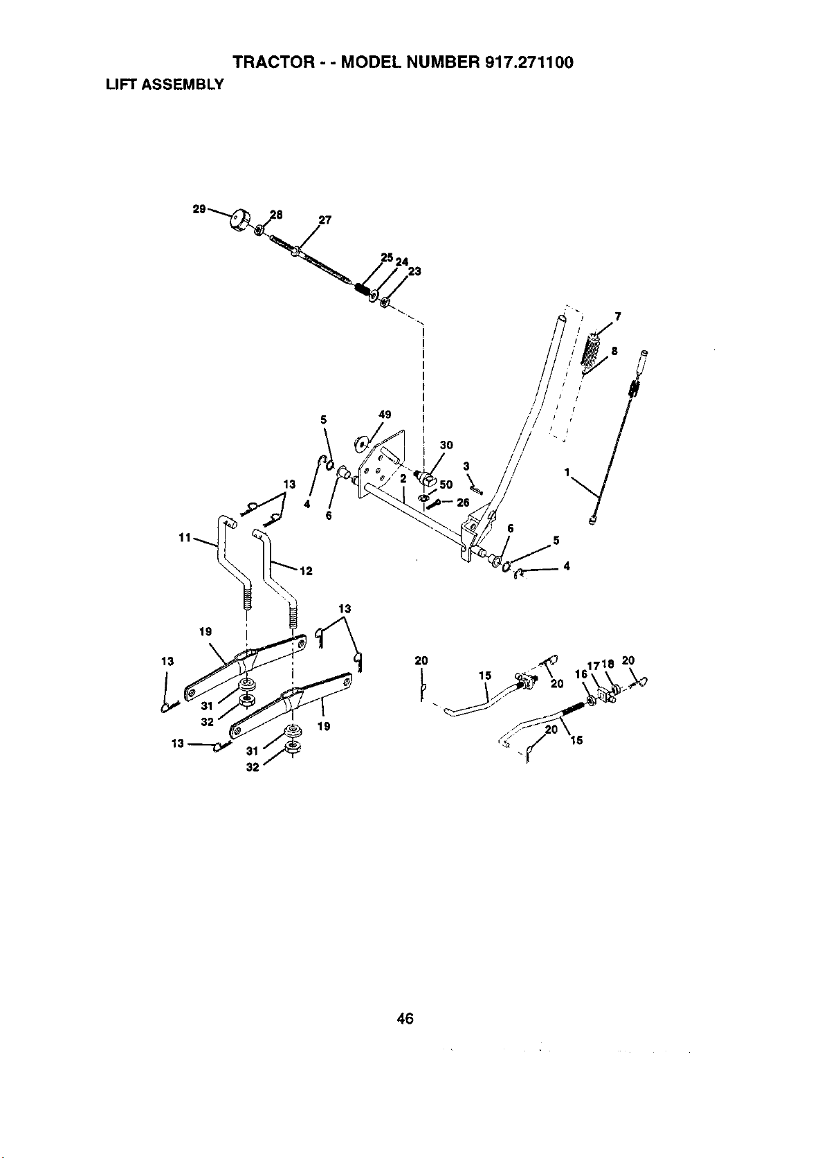
TRACTOR - - MODEL NUMBER 917.271100
LIFT ASSEMBLY
27
46
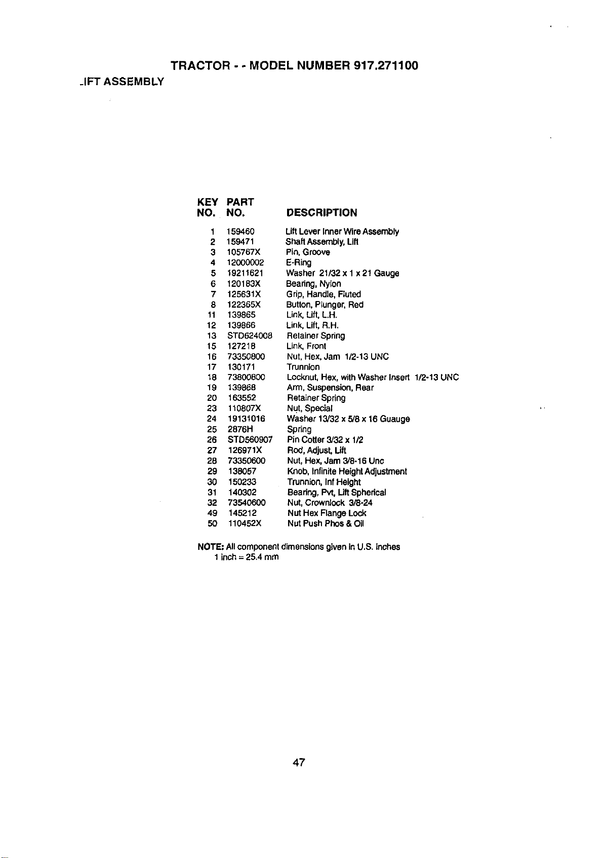
TRACTOR - - MODEL NUMBER 917.271100
.IFT ASSEMBLY
KEY PART
NO. NO. DESCRIPTION
1 159460 LiftLever Inner WireAssembly
2 159471 Shaft Assembly,Lift
3 105767X Pin,Groove
4 12000002 E-Ring
5 19211521 Washer 21/32xl x21 Gauge
6 120183X Bearing, Nylon
7 125631X Grip, Handle, Ruted
8 122365X Button, Plunger, Red
11 139865 Link, Lift, L.H.
12 139866 Link, Lift, R.H.
13 STD624008 Retainer Spring
15 127218 Link, Front
16 73350800 Nut, Hex, Jam 1/2-13 UNC
17 130171 Trunnion
t8 73800800 Locknut, Hex, with Washer Insert 1/2-13 UNC
19 139868 Arm, Suspension, Rear
20 163552 Retainer Spring
23 110807X Nut, Special
24 1913t016 Washer 13/32 x 5/8 x 16 Guauge
25 2876H Spnng
26 STD560907 Pin Cotter3/32 x 1/2
27 126971X Rod, Adjust, Lift
28 73350600 Nut, Hex, Jam 3/8-16 Unc
29 138057 Knob, Infinite Height Adjustment
30 150233 Trunnion, Inf Height
31 140302 Beadng, Pvt, Lift Spherical
32 73540600 Nut,Crownieck 3/8-24
49 145212 Nut Hex FlangeLock
50 110452X Nut Push Phos&Oil
NOTE: Allcomponentdimensions given inU.S. inches
1inch= 25.4 mm
47
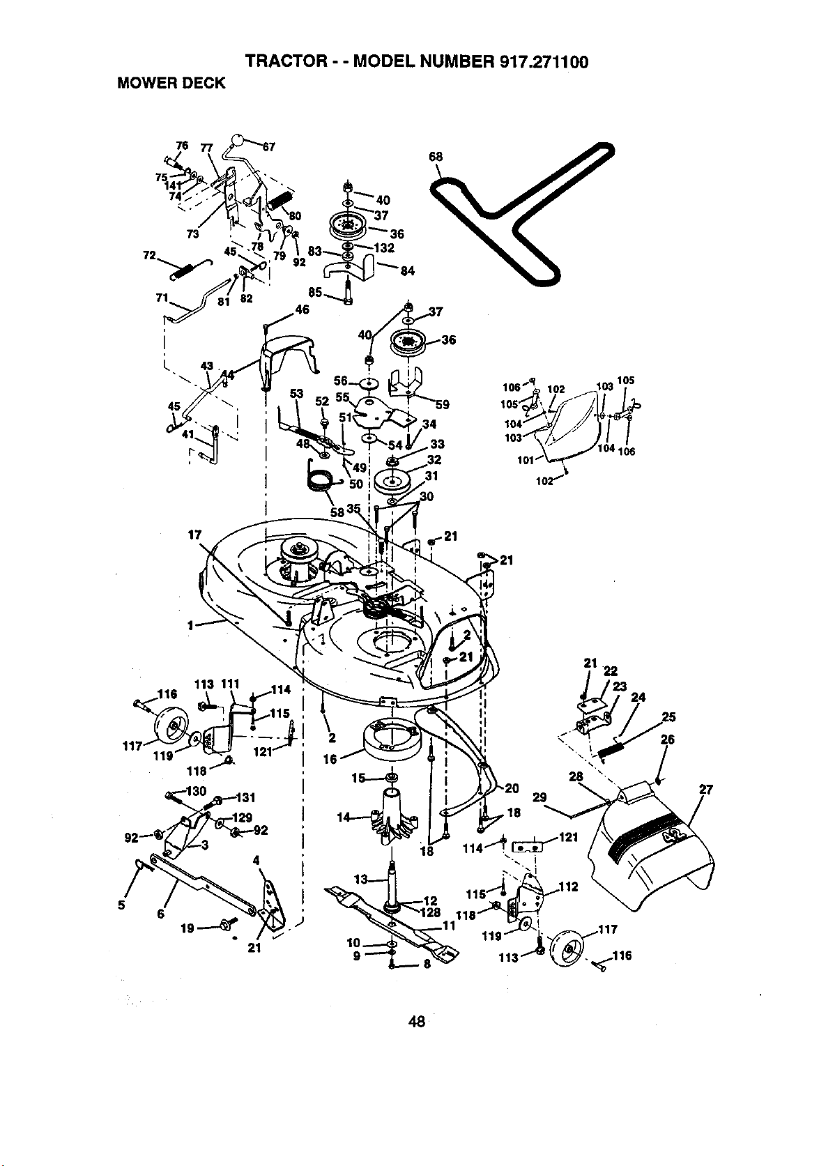
TRACTOR - - MODEL NUMBER 917.271100
MOWER DECK
17
68
31
58
>21
113 111 114 ,
\
2
16
18
21
22
t23
24
26
27
8
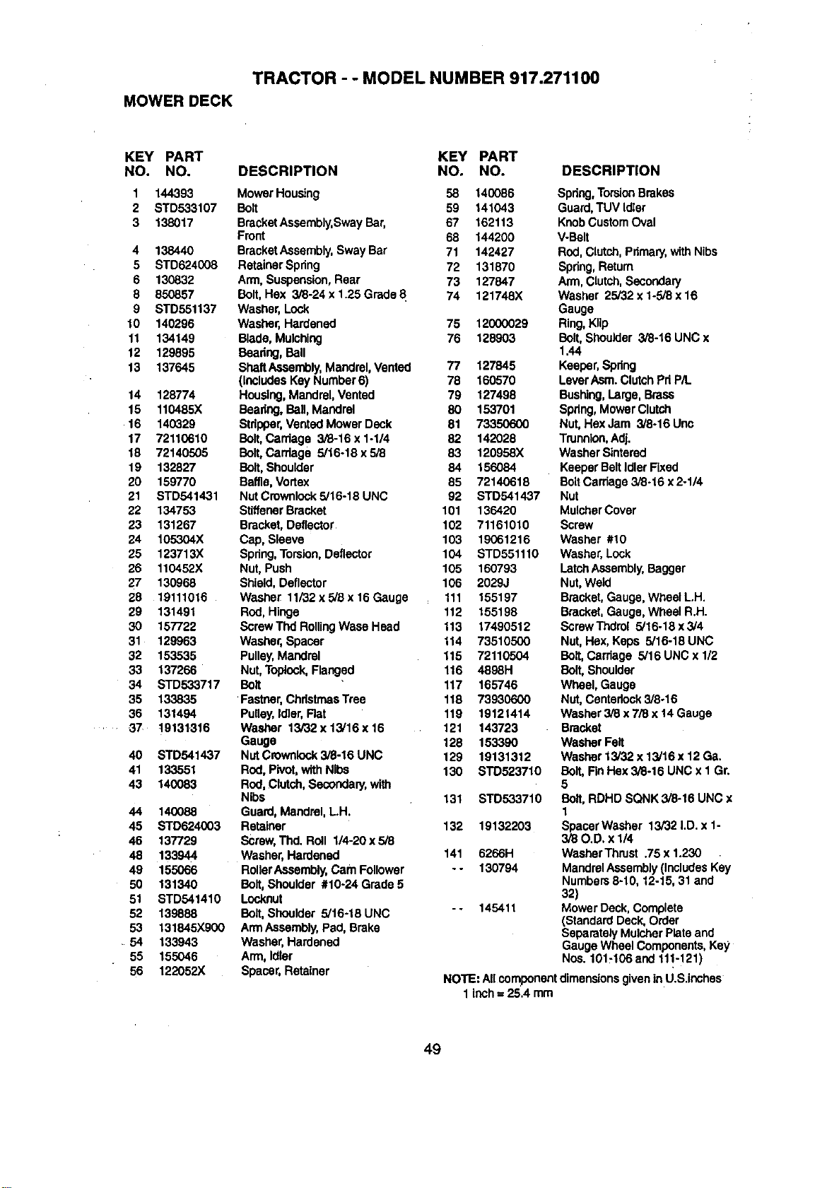
TRACTOR - - MODEL NUMBER 917.271100
MOWER DECK
KEY PART KEY PART
NO. NO. DESCRIPTION NO. NO. DESCRIPTION
1 144393 Mower Housing 58 140086 Spdng,TorsionBrakes
2 STD533107 Bolt 59 141043 Guard,TUVIdler
3 138017 BracketAssembly,SwayBar, 67 162113 KnobCustomOval
Front 68 144200 V-Belt
4 138440 BracketAssembly,Sway Bar 71 142427 Rod, Clutch,Pdmary,withNibs
5 STD624008 RetainerSpdng 72 131870 Spdng,Return
6 130832 Arm, Suspension,Rear 73 127847 Arm, Clutch,Secondary
8 850857 Belt, Hox 3/8-24 x 1.25 Grade 8 74 121748X Washer 25/32 x 1-5/8 x 16
9 STD551137 Washer, Lock Gauge
10 140296 Washer, Hardened 75 12000029 Ring,KIIp
11 134149 Blade, Mulching 76 128903 Bolt, Shoulder 3/8-16 UNC x
12 129895 Beadng, Bell 1.44
13 137645 shanAssembly, Mandrel,Vented 77 127845 Keeper, Spring
(includes KeyNumber 6) 78 160570 LeverAsm.ClutchPd P/t.
14 128774 Housing,Mandrel, Vented 79 127498 Bushing,Large, Brass
15 110485X Beadng,Ball, Mandrel 80 153701 Spdng,Mower Clutch
16 140329 Stdpper,VentedMower Deck 81 73350600 Nut, He:<Jam 3/8-16 Unc
17 72110610 Bolt,Carriage 3/8-16 x 1-1/4 82 142028 Trunnion,Adj.
18 72140505 Bolt, Carriage 5/16-18x5/8 83 120958X WasherSintered
19 132827 Bolt, Shoulder 84 156084 Keeper BeltIdler Fixed
20 159770 Baffle, Vortex 85 72140618 Bolt Carriage 3/8-16 x 2-1/4
21 STD541431 NutCrownlock5/16-18 UNC 92 STD541437 Nut
22 134753 StiffenerBracket 101 136420 MulcherCover
23 131267 Bracket, Deflector 102 71161010 Screw
24 105304X Cap, Sleeve 103 19061216 Washer #10
25 123713X Spring,Torsion,Deflector 104 STD551110 Washer,Lock
26 110452X Nut, Push 105 160793 LatchAssembly,Bagger
27 130968 Shield, Deflector 106 2029J Nut, Weld
28 19111016 Washer 11/32xS/Bx16Gauge 111 155197 Bracket,Gauge, WheelL.H.
29 131491 Red, Hinge 112 155198 Bracket,Gauge, WheeIR.H.
30 157722 Screw Thd RollingWace Head 113 17490512 ScrewThdrol 5/16.18x3/4
31 129963 Washer, Spacer 114 73510500 Nut, Hax, Keps 5/16-18 UNC
32 153535 Pulley,Mandrel 115 72110504 Belt, Carriage 5/16 UNC x 1/2
33 137266 Nut,Toplock,Flanged 116 4898H Bolt, Shoulder
34 STD533717 Bolt 117 165746 Wheel, Gauge
35 133835 'Fastner, ChristmasTree 118 73930600 Nut,Centedock3/8-16
36 131494 PuUey,ldler, Rat 119 19121414 Washer3/8x7/Sxt4Gauge
.... 37 19131316 Washer 13i32x13/16x16 121 143723 Bracket
Gauge 128 153390 Washer Felt
40 STD541437 NutCrownlock3i8-16UNC 129 19131312 Washer13/32 x13/16 x12 Ga.
41 133551 ROd,Pivot,withNibs 130 STD523710 Bolt, Rn Hex 3/8-16 UNC x 1 Gr.
43 140083 Rod, Clutch,Secondary,with 5
Nibs 131 BTD533710 Bolt, RDHD SQNK 3/8-16 UNC x
44 140088 Guard, Mandrel,L.H. 1
45 STD624003 Retainer 132 19132203 SpacerWasher 13/32 I.D. x 1-
46 137729 Scraw,Thd. Roll 1/4-20x5/8 3i80.D. x1/4
48 133944 Washer, Hardened 141 6266H WasherThrust .75 x 1.230
49 155066 RollerAssembly,Cam Follower -- 130794 MandrelAssembly(IncludesKey
50 131340 Bolt,Shoulder #10-24 Grade 5 Numbers8-10, 12-15,31 and
51 STD541410 Locknut 32)
52 139888 Bolt,Shoulder 5/16-18 UNC -- 145411 Mower Deck, Complete
(Standard Deck, Order
53 131845X900 ArmAssembly, Pad, Brake SeparatelyMutcherPlate and
54 133943 Washer, Hardened Gauge Wheel Components,Key
55 155046 Arm, Idler Nos. 101-106and 111-121)
56 122052X Spacer,Retainer NOTE: AllcomponentdimensionsgiveninU.S.inches
1 Inch= 25.4 mm
49
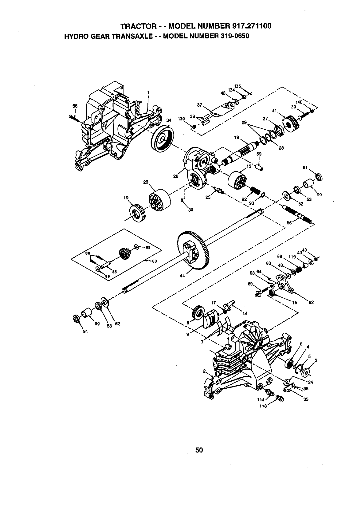
TRACTOR - - MODEL NUMBER 917.271100
HYDRO GEAR TRANSAXLE - - MODEL NUMBER 319-0650
34 139
23
19
28
59
35
5O
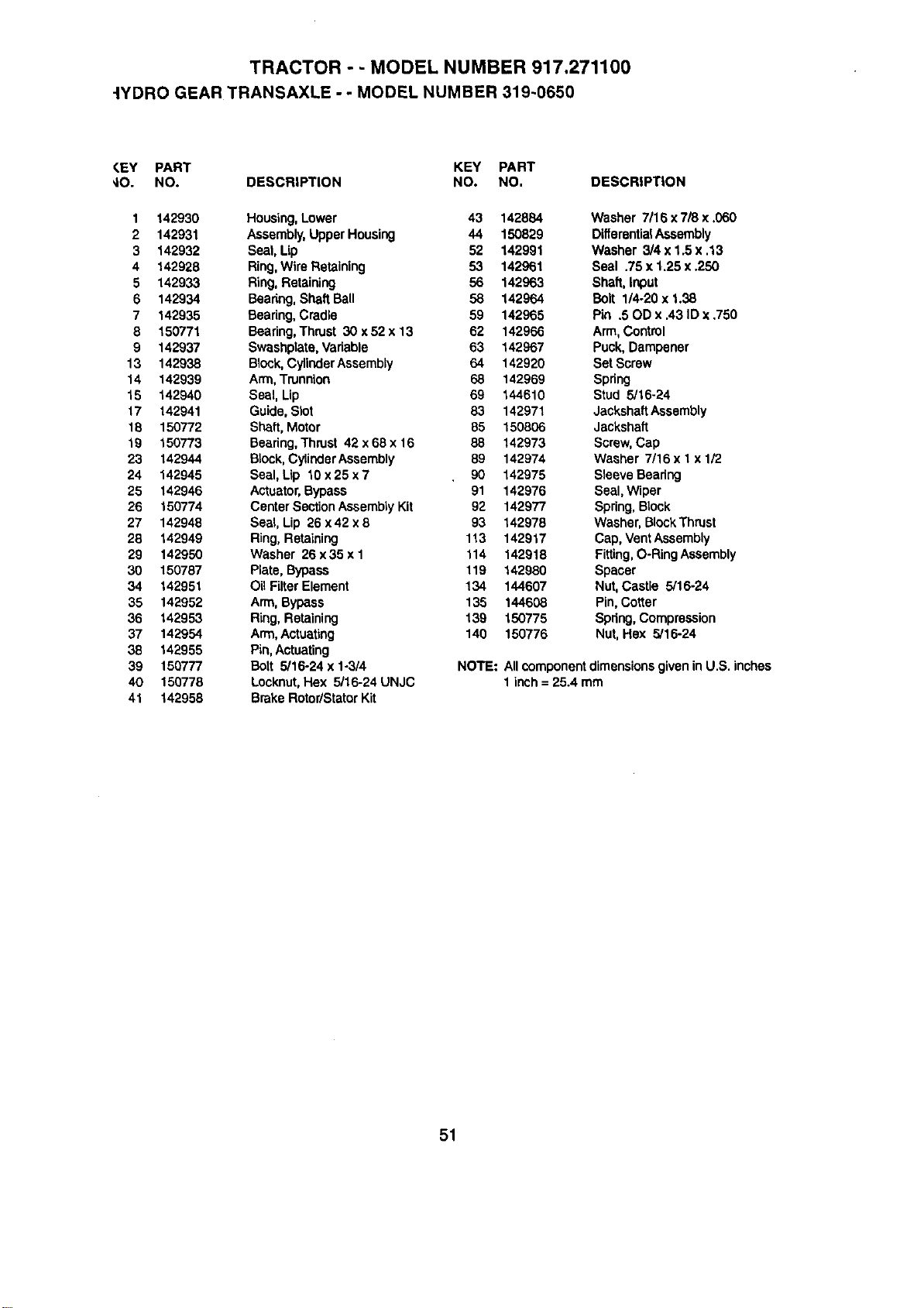
TRACTOR - - MODEL NUMBER 917.271100
-IYDRO GEAR TRANSAXLE - - MODEL NUMBER 319-0650
CEY PART KEY PART
_10. NO. DESCRIPTION NO. NO. DESCRIPTION
1 142930 Housing,Lower 43 142884 Washer 7116x7/8 x .060
2 142931 Assembly,Upper Housing 44 150829 DifferentialAssembly
3 142932 Seat, Up 52 142991 Washer 3/4 x 1.5 x .13
4 142928 Ring,Wire Retaining 53 142961 Seal .75 x 1,25 x .250
5 142933 Ring,Retaining 56 142963 ShaR,Input
6 142934 Bearing,Shaft Ball 58 142964 Bolt 1/4-20 x 1.38
7 142935 Bearing,Cradle 59 142965 Pin .50D x .43 ID x .750
8 150771 Bearing,Thrust 30 x 52 x 13 62 142966 Arm, Control
9 142937 Swashplata,Variable 53 142967 Puck, Dampener
13 142938 Bleck, CylinderAssembly 64 142920 SetScrew
14 142939 Arm, Trunnion 68 142969 Spring
15 142940 Seal, Lip 59 144510 Stud 5/16-24
17 142941 Guide,Slot 83 142971 JackshaftAssembly
18 150772 Shaft, Motor 85 150806 Jackshaft
19 150773 Bearing,Thrust 42 x68 x 16 88 142973 Screw,Cap
23 142944 Block,CylindarAssembly 89 142974 Washer 7/16 x 1x 1/2
24 142945 Seal, Lip 10 x 25 x 7 90 142975 Sleeve Bearing
25 142946 Actuator,Bypass 91 142976 Seal, Wiper
26 150774 Center SectionAssemblyKit 92 142977 Spring,Block
27 142948 Seal, Lip 26 x 42 x 5 93 142978 Washer, BlockThrust
28 142949 Ring,Retaining 113 142917 Cap, VantAssembly
29 142950 Washer 26x35 x I 114 142918 Fitting,O-RingAssembly
30 150787 Plate, Bypass 119 142980 Spacer
34 142951 Oil FilterElement 134 144507 Nut,Castle 5/16-24
35 142952 Arm,Bypass 135 144608 Pin, Cotter
36 142953 Ring,Retaining 139 150775 Sp_ng,Compression
37 142954 Arm,Actuating 140 150776 Nut, Hex 5/16-24
38 142955 Pin,Actuating
39 150777 Bctt 5/16-24 x 1-3/4 NOTE: Allcomponentdimensionsgiven inU.S. inches
40 150778 Locknut,Hex 5/16-24 UNJC 1inch = 25.4 rom
41 142958 Brake Rotor/StatorKit
51
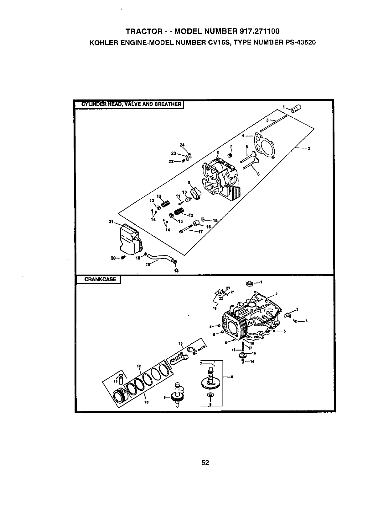
TRACTOR - - MODEL NUMBER 917.271100
KOHLER ENGINE-MODEL NUMBER CV16S, TYPE NUMBER PS-43520
CYLINDER HEAD, VALVE AND BREATHER I
1O
11
CRANKCASE J
52
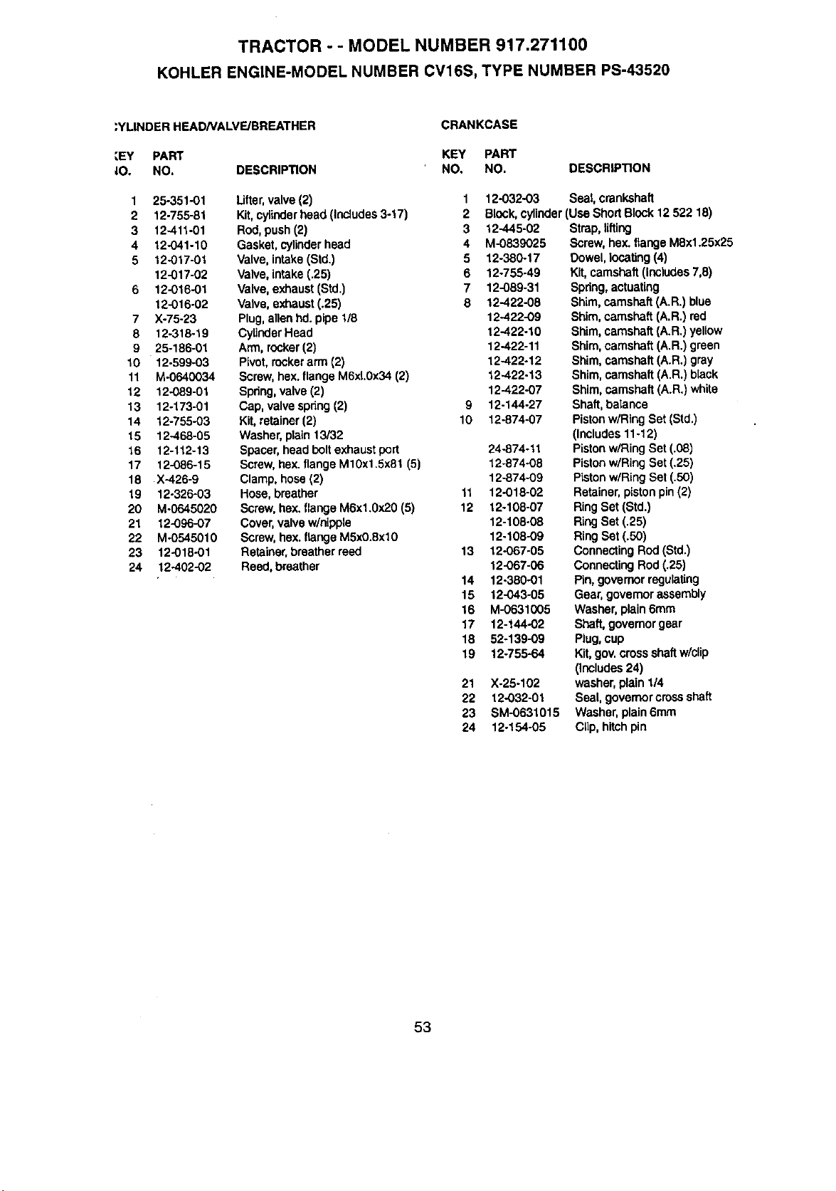
TRACTOR - - MODEL NUMBER 917.271100
KOHLER ENGINE-MODEL NUMBER CV16S, TYPE NUMBER PS-43520
;YLINDER HEAD/VALVE/BREATHER
:EY PART
40. NO.
CRANKCASE
1 25-351..01
2 12-755-81
3 12-411-01
4 12-041-10
5 12-017-01
12-017-02
6 12-016-01
12-016-02
7 X-75-23
8 12-318-19
9 25-186-01
10 12-599-03
11 M-0640034
12 12-089-01
13 12-173-01
14 12-755-03
15 12-468-05
16 12-112-13
17 12-086-15
18 X-426-9
19 12-326-03
20 M-0645020
21 12-096-07
22 M-0545010
23 12-018-01
24 12-402-02
KEY PART
DESCRIPTION NO. NO.
Lifter,valve(2)
Kit,cylinderhead (Includes3-17)
Rod,push(2)
Gasket, cylinderhead
Valve, intake(Std.)
Valve,intake(.25)
Valve,exhaust (Std.)
Valve,exhaust (.25)
Plug,allen hd.pipe 1/8
CylinderHead
Arm, rocker(2)
Pivot, rockerarm (2)
Screw,hax. flange M6xL0x34 (2)
Spring,valve (2)
Cap, valve spring(2)
Kit, retainer(2)
Washer,plain 13/32
Spacer, headboltexhaustport
Screw,hax. flangeM10x1.5x81 (5)
Clamp, hose(2)
Hose,breather
Screw,hax. flange M6xl.0x20 (5)
Cover,valvew/nipple
Screw,hax. flange M5xO.8xl0
Retainer,breatherreed
Reed, breather
DESCRIPTION
1
2
3
4
5
6
7
8
9
10
11
12
13
14
15
16
17
18
19
21
22
23
24
12-032-03 Seal, crankshaft
Block,cylinder(Use Short Block12 522 18)
12-445-02
M-0839025
12-380-17
12-755-49
12-089-31
12-422-08
12-422-09
12-422-10
12-422-11
12-422-12
12-422-13
12-422-07
12-144-27
12-874-07
24-874-11
12.874-08
12-874-09
12-018-02
12-108-07
12-108-08
12-108-09
12-067-05
12-067-06
12-380-01
12-043-05
M-0631005
12-144-02
52-139-09
12.755-64
X.25-102
12-032-01
SM-0631015
12-154-05
Strap,lifting
Screw, hex.flangeM8x1.25x25
Dowel,locating (4)
Kit,camshaft(Includes7,8)
Spdng,actuating
Shim,camshaft (A.R.) blue
Shim,camshaft (A.R.) red
Shim, camshaft(A.R.) yellow
Shim,camshaft(A.R.) green
Shim,camshaft(A.R.) gray
Shim,camshaft (A.R.) black
Shim,camshaft (A.R.) white
Shaft, balance
Pistonwiring Set(Std.)
(Includes 11.12)
Pistonw/Ring Set(.08)
Piston wiRing Set(.25)
Pistonw/Ring Set (.50)
Retainer,pistonpin(2)
RingSet (Std.)
RingSet (.25)
Ring Set (.50)
ConnectingRod(Std.)
ConnectingRod(.25)
Pin, governorregulaling
Gear, governorassembly
Washer, plain 6ram
Shaft, governorgear
Plug,cup
Kit, gov.crossshaftw/clip
(Includes24)
washer,plain1/4
Seal, governorcrossshaft
Washer, plain6ram
Clip, hitchpin
53
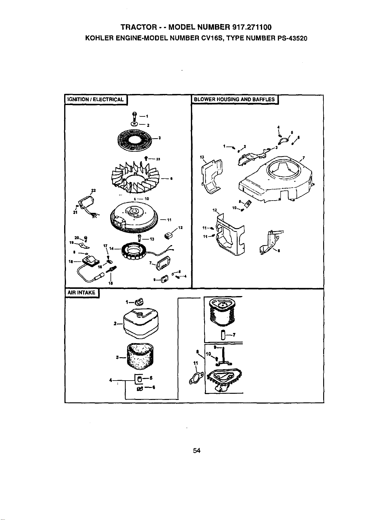
TRACTOR - - MODEL NUMBER 917.271100
KOHLER ENGINE-MODEL NUMBER CV16S, TYPE NUMBER PS-43520
IGNITION/ ELECTRICAL I
22
/
--2
I-- t0
--tl
_m13
AIR INTAKE i
BLOWERHOUSING AND BAFFLES I
54
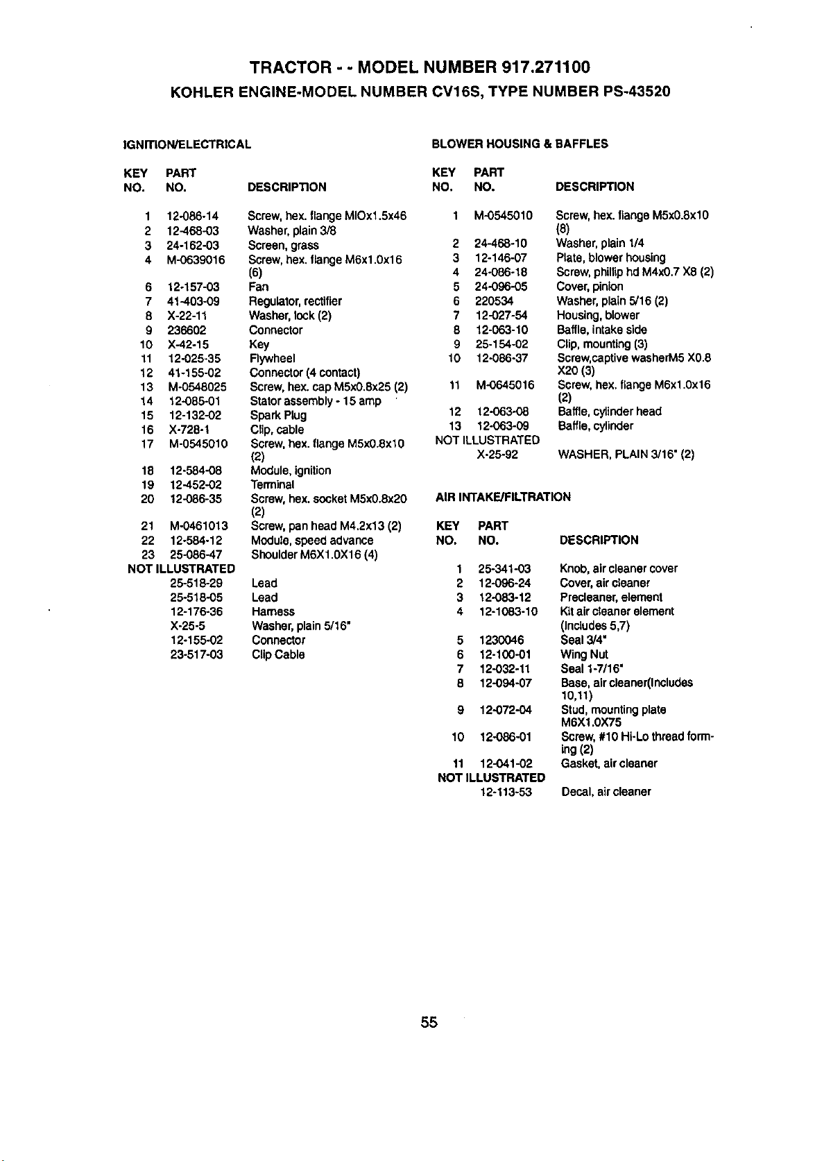
TRACTOR - - MODEL NUMBER 917.271100
KOHLER ENGINE-MODEL NUMBER CV16S, TYPE NUMBER PS-43520
IGNITION/ELECTRICAL
KEY PART
NO. NO. DESCRIPTION
1 12-086o14
2 12-468-03
3 24-162-03
4 M-0639016
6 t2-157-03
7 41-403-09
8 X-22-11
9 236602
10 X-42-15
11 12-025-35
12 41-155-02
13 M-0548025
14 12-085-01
15 12-132-02
16 X-728-1
17 M-0545010
18 12.584-08
19 12-452-02
20 12-086-35
21 M-0461013
22 12-584-12
23 25-086-47
NOT ILLUSTRATED
25-518-29
25-518-05
12-176-36
X-25-5
12-155-02
23-517-03
Screw,hex. flangeMIOx1.5x46
Washer, plain3/8
Screen, grass
Screw,hex.flange M6x1.0x16
(6)
Fan
Regulator,rectifier
Washer, lock(2)
Connector
Key
Rywheel
Connector(4 contact)
Screw,hex. cap MSxO.Sx25(2)
Statorassembly- 15 amp
Spark Plug
Clip, cable
Screw,hex.flange M5xO.8xl0
(2)
Module,ignition
Terminal
Screw,hex. socketMSx0.8x20
(2)
Screw,pan head M4.2x13 (2)
Module,speed advance
ShoulderM6X1.0X16 (4)
Lead
Lead
Hamess
Washe_ plain5/16"
Connector
Clip Cable
BLOWER HOUSING & BAFFLES
KEY PART
NO. NO. DESCRIPTION
1 M-0545010 Screw,hex. flangeM5xO.8xlO
(8)
2 24-468-10 Washer, plain 1/4
3 12-146-07 Plate, blower housing
4 24-086-18 Screw,phillip hd M4xO.7X8 (2)
5 24-096-05 Cover, pinion
6 220534 Washer, plain 5/16 (2)
7 12-027-54 Housing, blower
8 12-063-10 Baffle, intake side
9 25-154-02 Clip, mounting (3)
10 12-086-37 Screw,captivewasherM5 XO.8
X20 (3)
11 M-0645016 Screw,hex. flange M6x1.0x16
(2)
12 12-063-08 Baffle,cytinderhead
13 12-063-09 Baffle,cylinder
NOT ILLUSTRATED
X-25-92 WASHER, PLAIN 3/16" (2)
AIR INTAKE/FILTRATION
KEY PART
NO. NO.
1 25-341-03
2 12-096-24
3 12-083-12
4 12-1083-10
5 1230046
6 12-100-01
7 12-032-11
8 12-094-07
9 12-072-04
10 12-086-01
11 12-041-02
NOT ILLUSTRATED
12-113-53
DESCRIPT_N
Knob, air cleanercover
Cover,air cleaner
Precleaner,element
Kitair cleaner element
(Includes5,7)
Seal 3/4•
WingNut
Seal 1-7/16"
Base, aircleaner(Includes
10,11)
Stud,mountingplate
M6X1.0X75
Screw,#10 Hi-Lo threadform-
ing(2)
Gasket, aircleaner
Decal,air cleaner
55
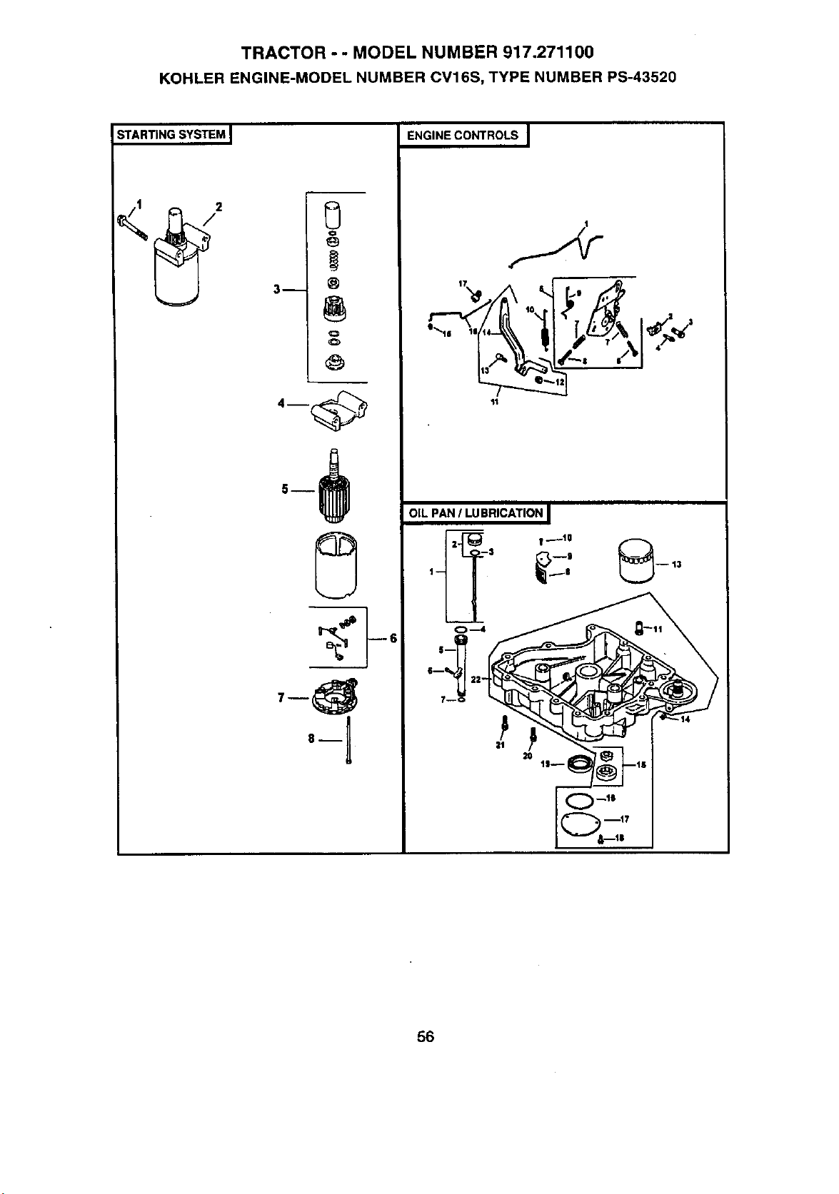
TRACTOR - - MODEL NUMBER 917.271100
KOHLER ENGINE-MODEL NUMBER CV16S, TYPE NUMBER PS-43520
STARTING SYSTEM I
3 h
0
Q
O
O
8_
ENGINE CONTROLS I
11
OIL PAN / LUBRICATION I
2
_.... 9 -- 13
t-- : 0
6--_ II 2=
O mll
11
56
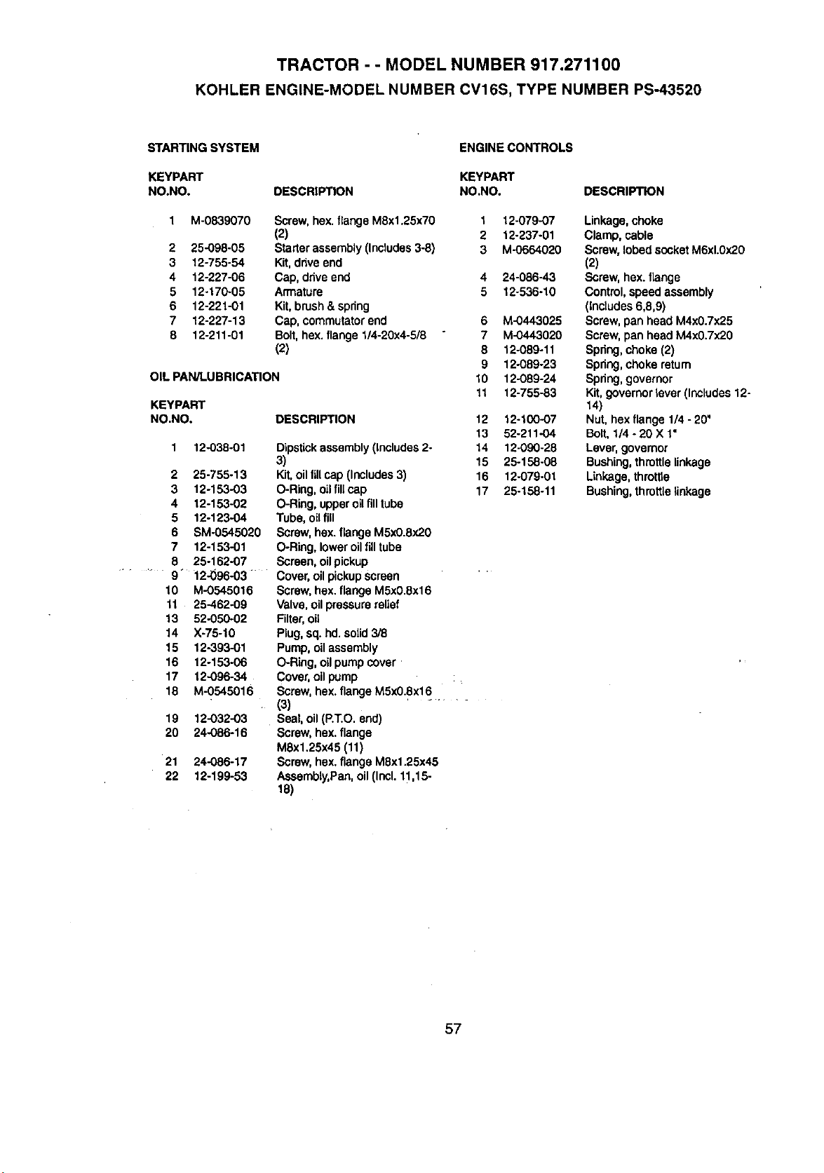
TRACTOR - - MODEL NUMBER 917.271100
KOHLER ENGINE-MODEL NUMBER CV16S, TYPE NUMBER PS-43520
STARTING SYSTEM
KEYPART
NO.NO.
ENGINE CONTROLS
2
3
4
5
6
7
8
M-0839070
25-098-05
12-755-54
12-227-06
12-170-05
12-221-01
12-227-13
12-211-01
KEYPART
DESCRIPTION NO.NO. DESCRIPTION
OIL PAN/LUBRICATION
Screw, hex.flangeM8x1.25x70
(2)
Starterassembly (Includes3-8)
Kit,drive end
Cap, drive end
Armature
Kit,brush& spring
Cap, commutatorend
Bolt,hex.flange 1/4-20x4-5/8
(2)
KEYPART
NO.NO. DESCRIPTION
1 12-038-01 Dipstickassembly(Includes2-
3)
2 25-755-13 Kit,oil fillcap (Includes3)
3 12-153-03 O-Ring,oil fill cap
4 12-153-02 O-Ring, upperoilfill tube
5 12-123-04 Tube, oilfill
6 SM-0545020 Screw,hex.flange M5x0.8x20
7 12-153-01 O-Ring, loweroilfilltube
8 25-162-07 Screen, oil pickup
9" 12-_96-03 " Cover,oil pickupscreen
10 M-0545016 Screw, hex. flange M5x0.8x16
11 25-462-09 Valve,oil pressurerelief
13 52-050-02 Filter,oil
14 X-75-10 Plug,sq.hd. solid3/8
15 12-393-01 Pump, oil assembly
16 12-153-06 O-Ring, oilpumpcover '
17 12-096.34 Cover,oil pump
18 M-0545016 Screw, hex.flange MSx0.8x16.
(3)
19 12-032-03 Seal, oil (P.T.O.end)
20 24-O86-16 Screw, hex.flange
MSx1.25x45 (11)
21 24-086-17 Screw, hex.flange M8x1.25x45
22 12-199-53 Assembly,Pan, oil (Incl.11,15-
18)
1 12-079-07 Linkage,choke
2 12-237-01 Clamp, cable
3 M-0664020 Screw,lobed socketM6xl.Ox20
(2)
4 24-086-43 Screw, hex. flange
5 12-536-10 Control,speed assembly
(Inctudes6,8,9)
6 M-0443025 Screw,pan head M4x0.7x25
7 M-0443020 Screw, pan head M4x0.7x20
8 12-089-11 Spring,choke(2)
9 12-089-23 Spring,choke return
10 12-089-24 Spring,governor
11 12-755-83 Kit, governorlever (Includes12-
14)
12 12-100-07 Nut,hex flange 114- 20"
13 52-211-04 Bolt,1/4 - 20 X 1"
14 12-090-28 Lever,governor
15 25-158-08 Bushing,throttlelinkage
16 12-079-01 Linkage,throttte
17 25-158-11 Bushing,throttlelinkage
57
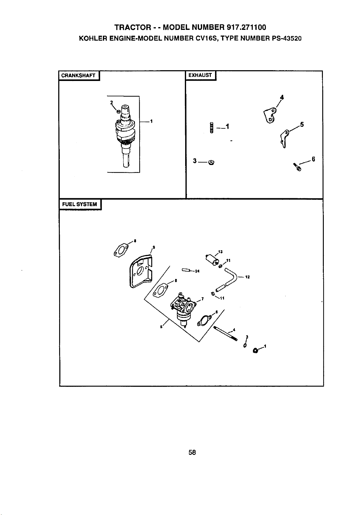
TRACTOR -- MODEL NUMBER 917.271100
KOHLER ENGINE-MODEL NUMBER CV16S, TYPE NUMBER PS-43520
CRANKSHAFT I
ql
3m_
FUEL SYSTEM I
58
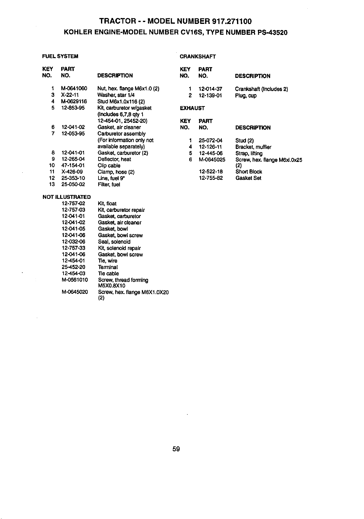
TRACTOR - - MODEL NUMBER 917.271100
KOHLER ENGINE-MODEL NUMBER CV16S, TYPE NUMBER PS-43520
FUEL SYSTEM
KEY PART
NO. NO,
1 M-0641060
3 X-22-11
4 M-0629116
5 12-853-95
6 12-041-02
7 12-053-95
8 12.,041-01
9 12-265-04
10 47-154-01
11 X-426-09
12 25,-353-10
13 25-050-02
NOT ILLUSTRATED
12-757-02
12-757-03
12-041-01
12-041-02
12-041-05
12-041-06
12-032-06
12-757-33
12-041-06
12-454-01
25-452-20
12-454-03
M-0561010
M-0645020
DESCRIPTION
Nut,hex. flangeM6xl.0 (2)
Washer,star 1/4
StudM6x1.0x116 (2)
Kit,carburetorw/gasket
(includes6,7,8 qty1
12-454-01, 25452-20)
Gasket, air cleaner
Carburetorassembly
(Forinformationonly not
availableseparately)
Gasket, carburetor(2)
Deflector,heat
Clipcable
Clamp,hose (2)
Une. fuel 9"
Filter,fuel
Kit,float
Kit,carburetor repair
Gasket, carburetor
Gasket, aircleaner
Gasket, bowl
Gasket, bowl screw
Seal, solenoid
Kit,solenoidrepair
Gasket. bowlscrew
-Re,wire
Terminal
"Becable
Screw,thread forming
M5XO.8X10
Screw, hex.flangeM6X1.0X20
(2)
• CFL_NKSHAFT
KEY PART
NO. NO.
1 12-014-37
2 12-139-01
EXHAUST
KEY PART
NO. NO,
1 25-072-04
4 12-126-11
5 12-445-06
6 M-0645025
12-522-18
12-755-82
DESCRIPTK)N
Crankshaft(Includes2)
Plug,cup
DESCRIPT_N
Stud(2)
Bracket,muffler
Strap, lifting
Screw, hex, flangeM6xl.Ox25
(2)
Short Block
Gasket Set
59

60

61

62
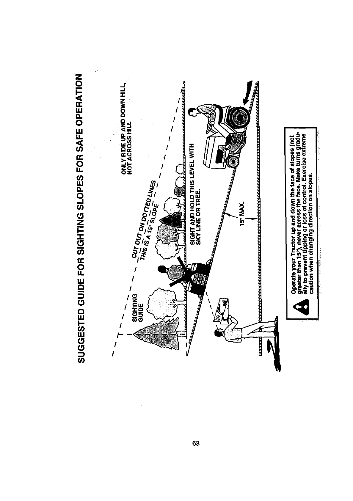
,., '-,Q
_.aQ
0 _
_mX_
I __"_'6.__
_ u--o''
€_.€
I _-_ _" =
Om _"
Io:jii
Oe •
63

For the repair or replacement parts you need
delivered directlyto your home
Call 7 am - 7 pm, 7 days a week
1-800-366-PART
(1-800-366-7278)
Para ordenar plezas con entrega a
domicil|o - 1-800-659-7084
For in-house major brand repair service
Call 24 hours a day, 7 days a week
1-800-4-REPAIR
(1-800-473-7274)
Para pedir servicio de reparaci6n a
domicillo - 1-800-676-5811
For the location of a Sears Parts and
Repair Center in your area
Call 24 hours a day, 7 days a week
1-800-488-1222
For information on purchasing a Sears
Maintenance Agreement or to inquire
about an existingAgreement
Call 9 am - 5 pm, Monday-Saturday
1-800-827-6655
mmmmnm
mmmmmm
When requesting service or ordering
parts, always provide the following
information:
• Product Type • Part Number
• Model Number • Part Description
SEARS
Amenca's Flepalr Speciattsts
168380 12.30.98 RD PdntedinU.S,A.