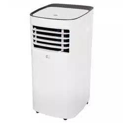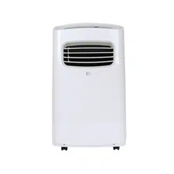
PORTABLE AIR CONDITIONER
OWNER’S MANUAL

For your own records, please attach a copy of your sales receipt to this manual and complete the following:
Model Number: _______________________________________ Serial Number: __________________________________________
Purchase Date: _______________________________________ Store Purchased: ________________________________________
Installation Date: ______________________________________ Installation Co.: _________________________________________
Installer Name: _______________________________________ Installer Phone No.: ______________________________________
CONSUMER PRODUCT INFORMATION
CONTENTS
SAFETY PRECAUTIONS ...................................................................1
IDENTIFICATION OF PARTS
...........................................................3
INSTALLATION INSTRUCTIONS
.....................................................5
CARE AND MAINTENANCE
............................................................10
AIR CONDITIONER FEATURES
.......................................................11
OPERATING INSTRUCTIONS
..........................................................12
TROUBLESHOOTING
.......................................................................14
CONTENTS
This manual provides the information needed for proper use and maintenance of this air conditioner. Basic
preventative care can help extend the life of this unit. The “Troubleshooting” section in this manual contains
a chart with solutions to the most common problems. Referring to this section may save time and prevent the
need for a service call in the event of a problem.
NOTE: The Energy Rating for this unit is based on an installation using an unextended exhaust duct without adapters A or
B (as shown in the Installation Section of this manual).
ENERGY SAVING TIPS
• Use the unit in the recommended room size.
• Locatetheunitwherefurniturecannotobstructtheairow.
• Keep blinds/curtains closed during the sunniest part of the day (cooling mode).
• Keeptheltersclean.
• Keep doors and windows closed to keep cool air in and warm air out (cooling mode) or keep warm air in and cool air out (heating mode for
units with heat function).
NOTE: All the illustrations in this manual are for explanation purposes only. Unit purchased may be slightly different.
Thedesignandspecicationsaresubjecttochangewithoutpriornoticeforproductimprovement.ContactConsumerServicesat844-4PA-AIRE
(844-472-2473)fordetails.
OPERATING CONDITIONS
The air conditioner must be operated within the temperature range indicated below:
MODE ROOM TEMPERATURE
COOL
62°F(17°C)–86°F(35°C)
DRY 55°F(13°C)–86°F(35°C)
NOTE: Performance may be
reduced outside of these operating
temperatures.
1
WARNING
DO NOTstoreorusegasolineorotherammablevaporsandliquidsinthevicinityofthisoranyotherappliance.
DO NOTuseanextensioncordoranadapterplug;avoidrehazardorelectricshock.Donotremoveanyprongfromthepower
cord..
Besuretheelectricalserviceisadequateforthemodelyouhavechosen.Thisinformationcanbefoundontheserialplate,whichis
located on the side of the cabinet and behind the grille.
Besuretheairconditionerisproperlygrounded.Tominimizeshockorrehazards,propergroundingisimportant.Thepowercordis
equippedwithathree-pronggroundingplugforprotectionagainstshockhazards.
Yourairconditionermustbeusedinaproperlygroundedwallreceptacle.Ifthewallreceptacleyouintendtouseisnotadequately
groundedorprotectedbyatimedelayfuseorcircuitbreaker,haveaqualiedelectricianinstalltheproperreceptacle.
Ensure the receptacle is accessible after the unit installation.
READ SAFETY PRECAUTIONS BEFORE INSTALLATION
Topreventinjurytotheuserorotherpeopleandpropertydamage,thefollowinginstructionsmustbefollowed.
Incorrect operation due to ignoring of instructions may cause harm or damage.
NEVER DO THIS. ALWAYS DO THIS.
SAFETY PRECAUTIONS
CAUTION
• Contactaqualiedinstallerforinstallationofthisunitifnecessary.
• Contactaqualiedservicetechnicianforrepairormaintenanceofthisunit.
• The air conditioner is not intended for use by young children without supervision. Young children should be supervised to ensure that they do
not play with the air conditioner.
• If the power cord is to be replaced, replacement work should be performed by authorized personnel only.
• Installation and repair work must be performed in accordance with the national wiring standards by authorized personnel only.
• DO NOT operate your air conditioner in a wet room such as a bathroom or laundry room.
• This appliance can be used by persons with reduced physical, sensory or mental capabilities or lack of experience and knowledge if they have
been given supervision or instruction concerning use of the appliance in a safe way and understand the hazards involved. Cleaning and user
maintenance shall not be made by children without supervision.
• Children should be supervised to ensure that they do not play with the appliance.
• Disabledpersonsmayrequireassistancewithsetupand/oruse.
• DO NOToperatetheappliancewithadamagedcordorplug.CallConsumerServicesat844-472-2473ifthepowersupplycordand/orplug
isdamaged;itmustbereplacedbyaqualiedservicetechnicianinordertoavoidahazard.
• Prior to cleaning or other maintenance, the appliance must be disconnected from its main power supply.
• DO NOT install the appliance in a location that may be exposed to combustible gas.
• Ifcombustiblegas(orotherammableliquidsorvapors)accumulatesaroundtheunit,itmaycausere.
• DO NOT run cord under carpeting. Do not cover cord with throw rugs, runners, or similar coverings. Do not route cord under furniture or
appliances.Arrangecordawayfromtrafcareaandwhereitwillnotbetrippedover.
• Toreducetheriskofreorelectricshock,donotusetheappliancewithanysolid-statespeedcontroldevice.
• The appliance shall be installed in accordance with national wiring regulations.
• When there are differences between “USER MANUAL” and “Remote Control Manual” on function description, the description on “USER MANUAL
“ shall prevail.

2
SAFETY PRECAUTIONS
Please read through these instructions before you start the installation process. Improper installation can cause damage to the unit, your personal
property, and also poses a personal safety hazard.
• Installationmustbeperformedaccordingtotheinstallationinstructions.Improperinstallationcancausewaterleakage,electricalshock,orre.
• Useonlytheincludedaccessoriesandparts,andspeciedtoolsfortheinstallation.Usingnon-standardpartscancausewaterleakage,
electricalshock,re,andinjuryorpropertydamage.
• Makesurethattheoutletyouareusingisgroundedandhastheappropriatevoltage.Thepowercordisequippedwithathree-pronggrounding
plug to protect against shock. Voltage information can be found on the side of the unit, behind the grille. If the wall receptacle you intend to use
isnotadequatelygroundedorprotectedbyatimedelayfuseorcircuitbreaker,haveaqualiedelectricianinstalltheproperreceptacle.
• Ensure the receptacle is accessible after the unit installation.
• Installtheunitonaat,level,sturdysurface.Failuretodosocouldresultindamageorexcessivenoiseandvibration.
• The unit must be kept free from obstruction to ensure proper function and to mitigate safety hazards.
• DO NOT modify the length of the power cord or use an extension cord to power the unit.
• DO NOTshareasingleoutletwithotherelectricalappliances.Improperpowersupplycancausereorelectricalshock.
• DO NOT remove any prong from the power cord.
• DO NOT install your air conditioner in a wet room such as a bathroom or laundry room. Too much exposure to water can cause electrical
components to short circuit. Your air conditioner should be used in such a way that it is protected from moisture (i.e. condensation, splashed
water,etc.).Donotplaceyourairconditionerwhereitcanfallorbepulledintowateroranyotherliquid.Iftheunitdoeseverfallintowater,
unplug it immediately.
• DO NOTinstalltheunitinalocationthatmaybeexposedtocombustiblegasorotherammableliquidsorvaporsasthiscouldcausere.
• Theunithaswheelstofacilitatemoving.Makesurenottousethewheelsonthickcarpetortorolloverobjects,asthesecouldcausetipping.
Always transport your air conditioner in a vertical position and stand on a stable, level surface during use.
• DO NOT operate a unit that has been dropped or damaged.
• DO NOTremoveanyxedcoversfromtheunit.
• Onlyusetheincludedaccessoriesandspeciedpartsforinstallation.Usingnonstandardpartscancausewaterleakage,electricalshock,re,
andinjuryorpropertydamage.
• Theunitmustbekeptfreefromobstructiontoensureproperfunction.Keepanairpathofatleast12in(30cm)allaroundtheunitfromalls,
furniture, and curtains.
• DO NOT allow children to play with the air conditioner. Children must be supervised around the unit at all times.
• If the air conditioner is knocked over during use, turn the unit off and unplug it from the main power supply immediately. Visually inspect the
unit to ensure there is no damage. If you suspect the unit has been damaged, contact a technician or customer service for assistance.
• In a thunderstorm, the power must be cut off to avoid damage to the machine due to lightning.
• Turn off the product when not in use.
• DO NOT touch the unit or plug with wet or damp hands or when barefoot.
• DO NOTpressthebuttonsonthecontrolpanelwithanythingotherthanyourngers.
• DO NOTremoveanyxedcovers.Neverusethisapplianceifitisnotworkingproperlyorifithasbeendropped
or damaged.
• Never use the plug to start or stop the unit. (Always use the switch on the control panel or remote to power the unit on and off.)
• DO NOT use this product for functions other than those described in the instruction manual.
3
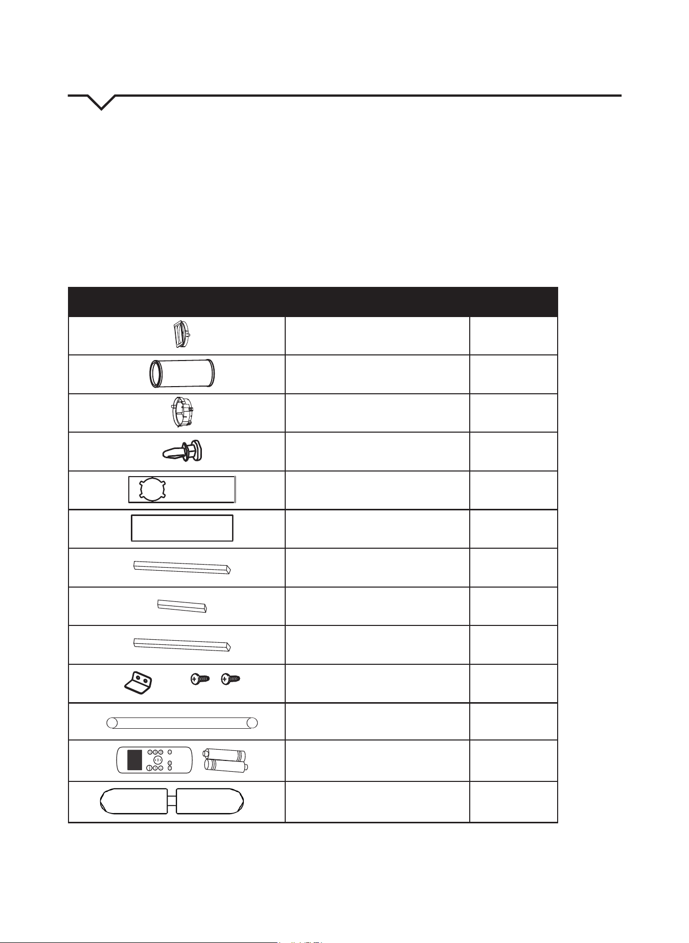
IDENTIFICATION OF PARTS
ACCESSORIES
Checkthatalltheaccessoriesareincludedinthepackage(Fig.1)andrefertotheinstallationinstructionsfortheirusage.YourWindowInstallation
Kittswindows26.5–48inches(67.5–123cm)andcanbeshortenedforsmallerwindows.
Tools Needed:
• Medium Phillips screwdriver
• Tape measure or ruler
• Knife or scissors
• Saw (optional, to shorten window adapter for narrow windows)
PART DESCRIPTION QUANTITY
Unit Adapter 1pc
Exhaust Hose 1pc
Window slider Adapter 1pc
Bolt 1pc
Window Slider A 1pc
Window Slider B 1pc
Foam Seal A (Adhesive) 2pcs
Foam Seal B (Adhesive) 2pcs
FoamSealC(Non-Adhesive) 1pc
SecurityBracketand2Screws 1set
Drain Hose 1pc
Remote Control and Batteries 1set
Power cord buckle 1pc
NOTE: All of the illustrations in this manual are for explanation purposes only. Your air conditioner may be slightly different.
FIG. 1
4
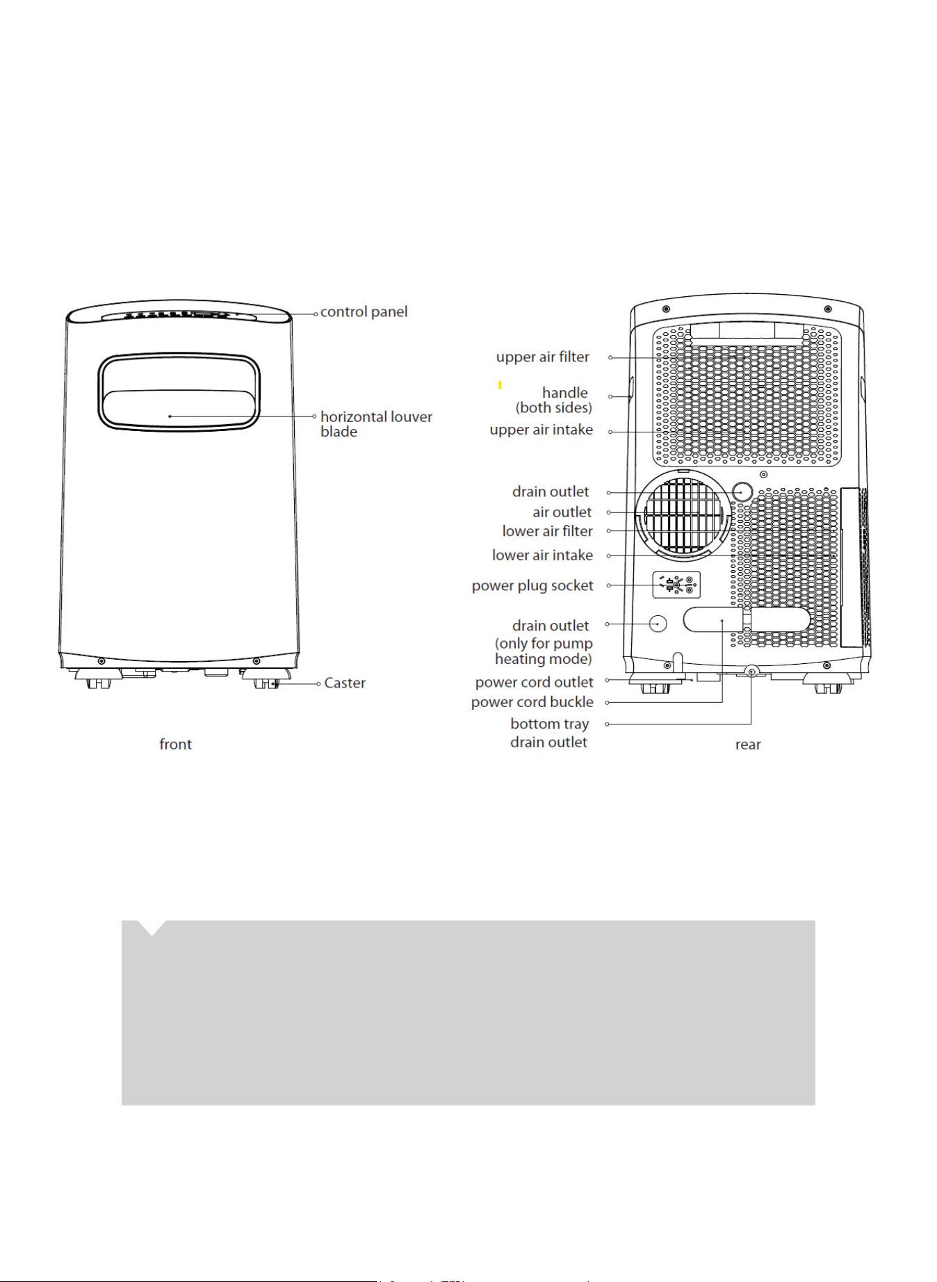
PARTS DIAGRAM
ABOUT FLUORINATED GASES
• This air conditioning unit is a hermetically sealed unit that contains fluorinated gases. For specific information on the
type of gas and the amount, please refer to the relevant label on the unit itself.
• Installation, service, maintenance and repair of this unit must be performed by a certified technician.
• Product uninstallation and recycling must be performed by a certified technician.
• Whentheunitischeckedforleaks,properrecord-keepingofallchecksisstronglyrecommended.
FRONT BACK
5
INSTALLATION INSTRUCTIONS
LOCATION
• The air conditioner should be placed on a firm surface
to minimize noise and vibration. For safe and secure
positioning, place the unit on a smooth, level floor strong
enough to support it.
• The unit has casters to aid placement; it should only be
rolled on smooth, flat surfaces. Use caution when rolling
on carpeted surfaces. Do not attempt to roll the unit over
objects.
• The unit must be installed near a grounded plug; the Collecti/
on Tray Drain (found on the back of the unit) must be
accessible.
• DO NOT cover the Intakes, Outlets or Remote Signal Receptor
of the unit, as this could prevent the unit from running
efficiently and can damage the unit.
• Allowatleast12inches(30cm)ofspacefromthewallfor
efficientair-conditioning.(SeeFig4.)
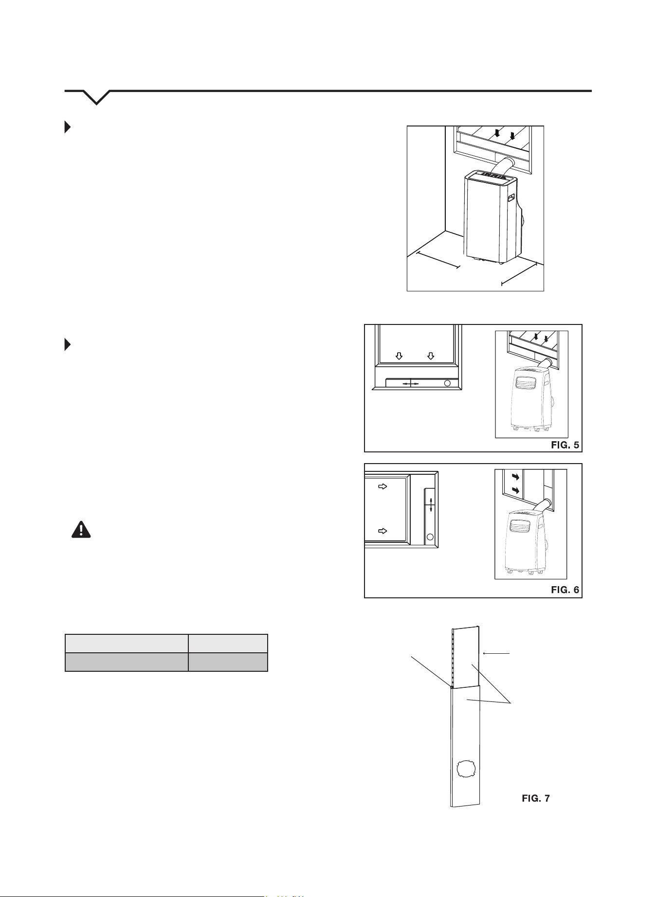
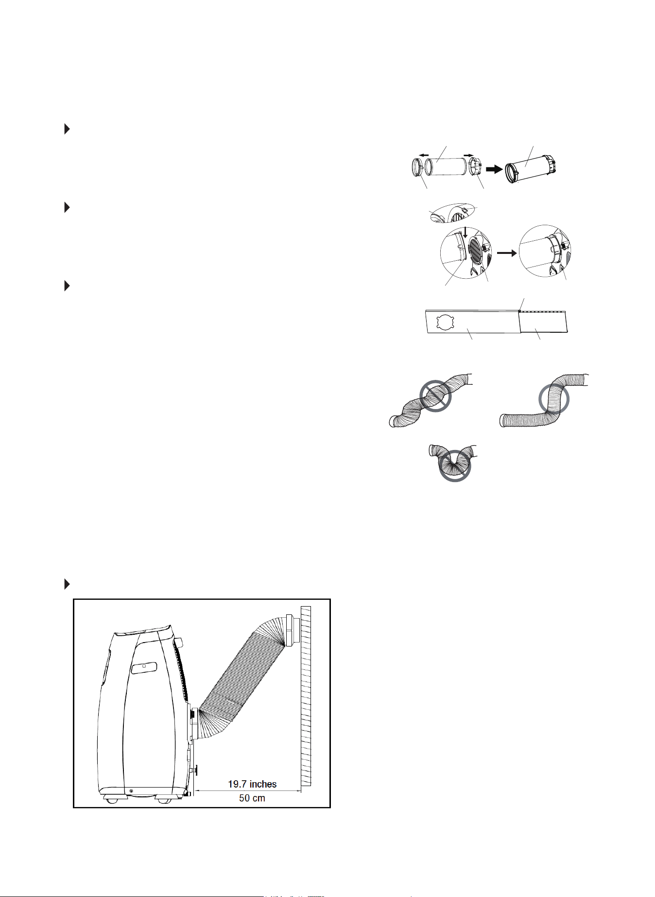
WINDOW SLIDER KIT INSTALLATION
Yourwindowsliderkithasbeendesignedtotmoststandard
“vertical” and “horizontal” window applications. However, it may
be necessary for you to improvise or modify some aspects of
the installation procedures for certain types of windows. Please
refertoFig.5andFig.6forminimumandmaximumwindow
openings.Windowsliderkitlengthcanbexedwithabolt.(See
Fig.7.)
NOTE:Ifthewindowopeningislessthan2ft.,cutthe
extensionpiece(SeeFig.7)shortersothekitproperlytsinthe
window opening. Only cut if absolutely necessary. Never cut the
hole in the window slider kit.
CAUTION
Make sure there are no obstacles around the air outlet of the
exhausthose(intherangeof20in./500mm)inorderforthe
exhaust system to
work properly.
The exhaust hose and adapter must be installed or removed in
accordance with the usage mode as indicated below:
COOL or AUTO mode Install Hose
FAN or DRY mode Remove Hose
12in.
(30cm)
12in.
(30cm)
FIG. 4
Vertical
Window
Horizontal
Window
Extension
Piece
Window Slider Kit
Bolt
Window Slider Kit
Minimum:2ft.(67cm)
Maximum:4ft.(123cm)
Window Slider Kit
Minimum:2ft.(67cm)
Maximum:4ft.(123cm)
6
STEP 1:
PREPARING THE EXHAUST HOSE
ASSEMBLY Fig. 8
Slide the exhaust hose into the window slider adapter and unit adapter; it
will snap automatically to the adapters.
STEP 2:
INSTALL THE EXHAUST HOSE ASSEMBLY
TO THE UNIT Fig. 9
Slide the Exhaust hose assembly into the air outlet opening of the unit along
the arrow direction, from left to right.
STEP 3:
PREPARING THE ADJUSTABLE WINDOW
SLIDER Fig. 10
a. Depending on the size of your window, choose the correct sliders and
adjustaccordingly.Sometimescuttingtheslidermaybenecessaryto
properly install. Please take extra care when cutting, and cut only when
absolutely necessary. Do not cut the hole in the window slider kit.
b. Ifthelengthofthewindowrequirestwowindowsliders,usethebolt
(included)tofastenthewindowslidersoncetheyareadjustedtothe
proper length.
NOTE: To ensure proper function, DO NOT overextend or bend the
hose. Make sure that there are no obstacles around the air outlet of the
exhausthose(20inchclearance)inordertoensuretheexhaustsystem
worksproperly.(Fig.11.)
Once the Exhaust Hose assembly is prepared, choose from one of the
following two installation methods:
• HungWindowInstallation(page7)
• SlidingWindowInstallation(page8)
Unit Adapter
Bolt (if needed)
Window Slider A Window Slider B
Window Slider Adapter
Exhaust Hose Exhaust Hose Assembly
FIG. 8
FIG. 9
FIG 10. 10
FIG . 11
RECOMMENDED INSTALLATION
NOTE: All the illustrations in this manual are for
explanation purposes only. Your unit may be slightly
different. The actual shape of the unit prevails.
The unit can be controlled by it’s control panel
or with the remote control. This manual does not
include remote control operations. See the Remote
Control User Manual included with the unit for
details.
7
T YPE 1:
HUNG WINDOW INSTALLATION
STEP 1 Fig. 12
Cut the adhesive foam seal A and B strips to the proper lengths,
and attach them to the window sash and frame as shown.
STEP 2 Fig. 13
Insert the window slider assembly into the window opening.
STEP 3 Fig. 14
Cutthenon-adhesivefoamsealCstriptomatchthewidthof
the window. Insert the seal between the glass and the window
frame to prevent air and insects from getting into the room.
STEP 4 Fig. 15
Ifdesired,installthesecuritybracketwith2screwsasshown.
STEP 5 Fig. 16
Insert the window slider adapter into the hole of the window
slider.
NOTE: All the illustrations in this manual are for explanation
purposes only. Your unit may be
slightly different.
Foam Seal B
(Adhesivetype-shorter)
Foam Seal C
(Non-adhesive
type)
Window
Slider A
Window
Slider B
(ifrequired)
Foam Seal A
(Adhesive type)
Security Bracket
FIG. 12
FIG. 13
FIG. 14
FIG. 15
FIG. 16
2Screws
8
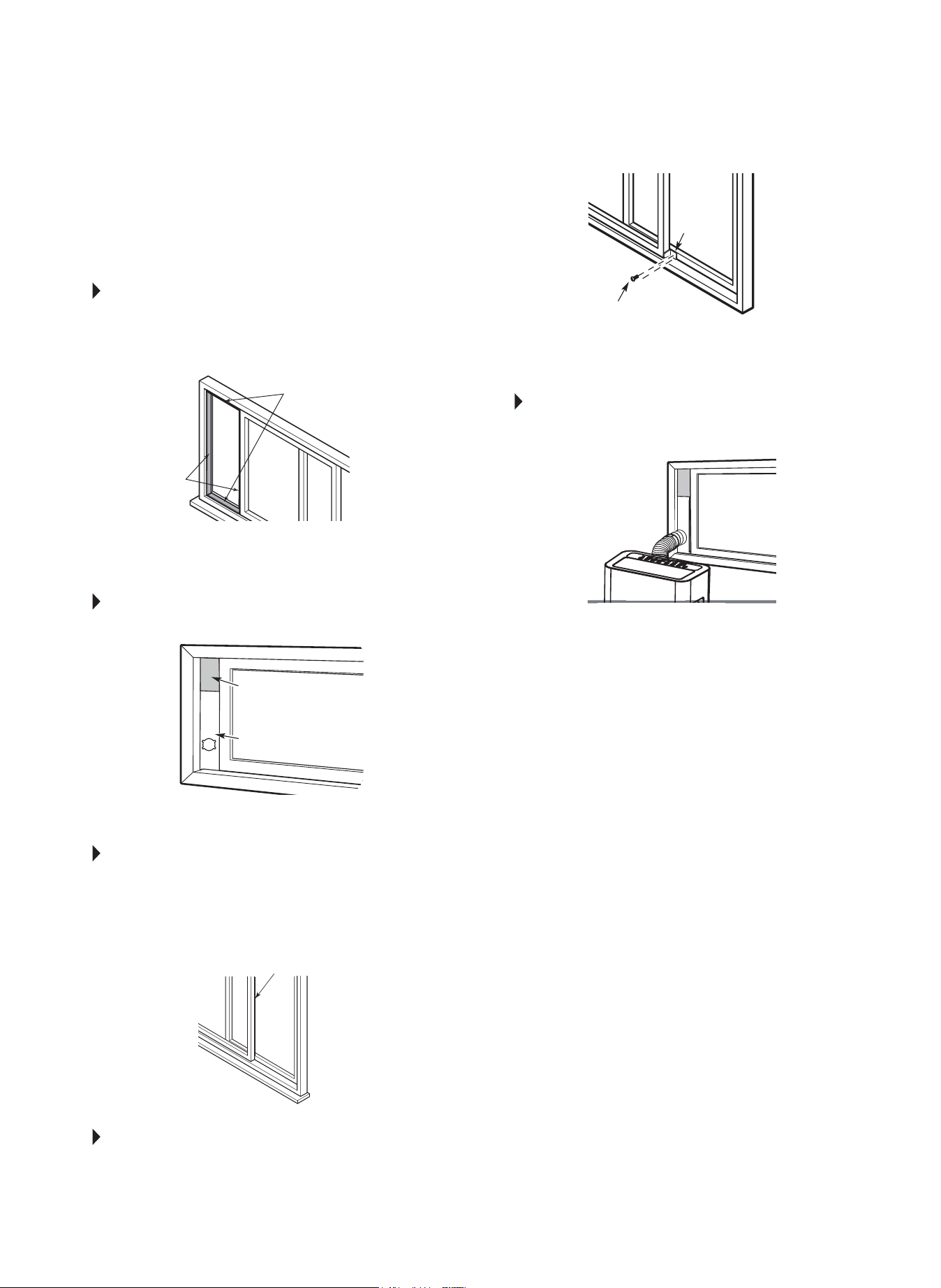
TYPE 2:
SLIDING WINDOW
INSTALL ATION
STEP 1 Fig. 17
Cut the adhesive foam seal A and B strips to the proper lengths,
and attach them to the window sash and frame as shown.
STEP 2 Fig. 18
Insert the window slider assembly into the window opening.
STEP 3 Fig. 19
Cutthenon-adhesivefoamsealCstriptomatchthewidthof
the window. Insert the seal between the glass and the window
frame to prevent air and insects from getting into the room.
STEP 4 Fig. 20
Ifdesired,installthesecuritybracketwith2screwsasshown.
STEP 5 Fig. 21
Insert the window slider adapter into the hole of the window
slider.
NOTE: All the illustrations in this manual are for explanation
purposes only. Your unit may be
slightly different.
FIG. 17
FIG. 18
FIG. 19
FIG. 20
FIG. 21
Foam Seal B
(Adhesivetype-shorter)
Foam Seal A
(Adhesive type)
Foam Seal C
(Non-adhesivetype)
Window
Slider A
Security
Bracket
2Screws
Window
Slider B
(ifrequired)
9
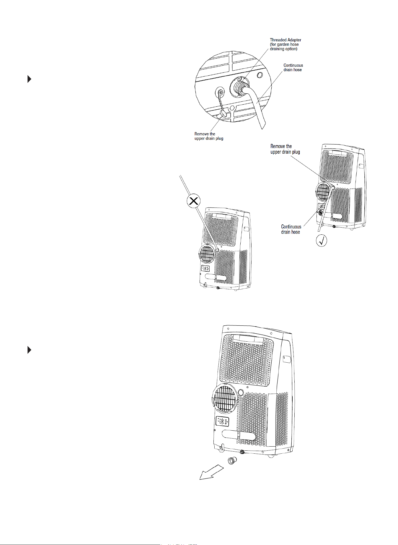
WATER DRAINAGE
During dehumidifying mode, remove the upper drain plug from
thebackoftheunitandattach3/4”vinyltubeincludedwith
theunit(5/8”outerdiameter).Ifalongerhoseisneeded,avinyl
tube(3/4”innerdiameter5/8”outerdiameter)canbepurchased
at a local hardware store or a standard garden hose (not
included) may be attached to the threaded adapter and used
for continuous draining. (A hose length of no greater than 6 ft is
recommended.) Place the open end of the hose directly over the
drainareainyouroor.Seeg22-Aand22-B.
NOTE: Make sure the hose is secure so there are no leaks.
Directthehosetowardaoordrain,makingsurethatthere
arenokinksthatwillstopthewaterow.Placetheendofthe
hose into a drain and make sure the end of the hose is directed
downwardtoletthewaterowsmoothly.(SeeFig.22-B.)Never
allowthehosetobedirectedupwardatanypoint.(Fig.22-C.)
P1 CODE WATER DRAINAGE
• During normal operation if the water level of the bottom tray
reachesapredeterminedlevel,theunitbeeps8times,and
thedigitaldisplayshows“P1”.
• Atthistimetheairconditioning/dehumidicationprocesswill
immediately stop. However, the fan motor will continue to
operate (this is normal).
• Carefully move the unit to a drain location, remove the bottom
drainpluganddrainthewater.Fig.22-D
• Reinstall the bottom drain plug and restart the machine until
the“P1”symboldisappears.Iftheerrorrepeats,callfor
service.
NOTE: Be sure to reinstall the bottom drain plug
before using the unit.
FIG. 22-A
FIG. 22-B
FIG. 22-C
FIG. 22-D
Upper filter
(install)
Power Plug
Socket

10
IMPORTANT SAFETY PRECAUTIONS
1. ALWAYSunplugtheunitbeforecleaningorservicing.
2. DONOTuseammableliquidsorchemicalstocleantheunit.
3. DONOTwashtheunitunderrunningwatertoavoidanyelectricaldangers.
4. DONOToperatethemachineifthepowersupplycordhasbeendamaged
during cleaning. A damaged power cord must be replaced with a new cord
from the manufacturer.
AIR FILTER MAINTENANCE
REMOVAL:Thisunithasthreelters.Taketheupperlterout
alongthearrowdirectionasshowninFig.23-A.Removethelower
lters(A&B)asshowninFig.23-A.*RemovelowerlterAbefore
removinglowerlterB.
CLEANING:Washtheairltersbyimmersingthemgentlyinwarmwater(about
104°F/40°C)withamilddetergent.Rinsethelters
and dry them in a cool, dry place.
MOUNTING:Installtheupperandlowerairltersaftercleaningas
showninFig.23-B.Besuretousethescrewforthelowerlters.
NOTE:Theuppergrilleandupperairlterareconnectedandcannot
be separated.
CLEANING THE UNIT
Usealint-freeclothsoakedwithmilddetergenttocleantheunitenclosure,rinse
thourouglyandnishbyusingadry,cleancloth.Neveruseharshcleaners,waxor
polish on the cabinet front.
STORING THE UNIT WHEN NOT IN USE
1. Drainthewatercollectiontrayaccordingtotheinstructionsinthe“Water
Drainage” section.
2. RuntheapplianceonFANmodefor12hoursinawarmroomtodryitand
prevent mold.
3. Turnofftheapplianceandunplugit.Wrapthecordaroundthepowercord
buckle.
4. Cleantheairltersaccordingtotheinstructionsinthe“AirFilterMaintenance”
section.Reinstalltheclean,drylterbeforestoring.
5. Removethebatteriesfromtheremotecontrolanddisconnectallhoses.
Be sure to store the unit and installation accessories in a cool, dark place.
Exposure to direct sunshine or extreme heat can shorten the lifespan of the unit.
CARE AND MAINTENANCE
CAUTION
Be sure to clean the air filter every 2 weeks for optimal performance.
The water collection tray should be emptied immediately after P1 code appears.
FIG. 23-A
Upper filter
(take out)
Lower Filter A
(take out)
Lower Filter B
(take out)
Upper filter
(install)
Lower Filter A
(install)
Lower Filter B
(install)
FIG. 23-B
Power Plug
Socket
Power Cord
Power
Cord
Buckle
11
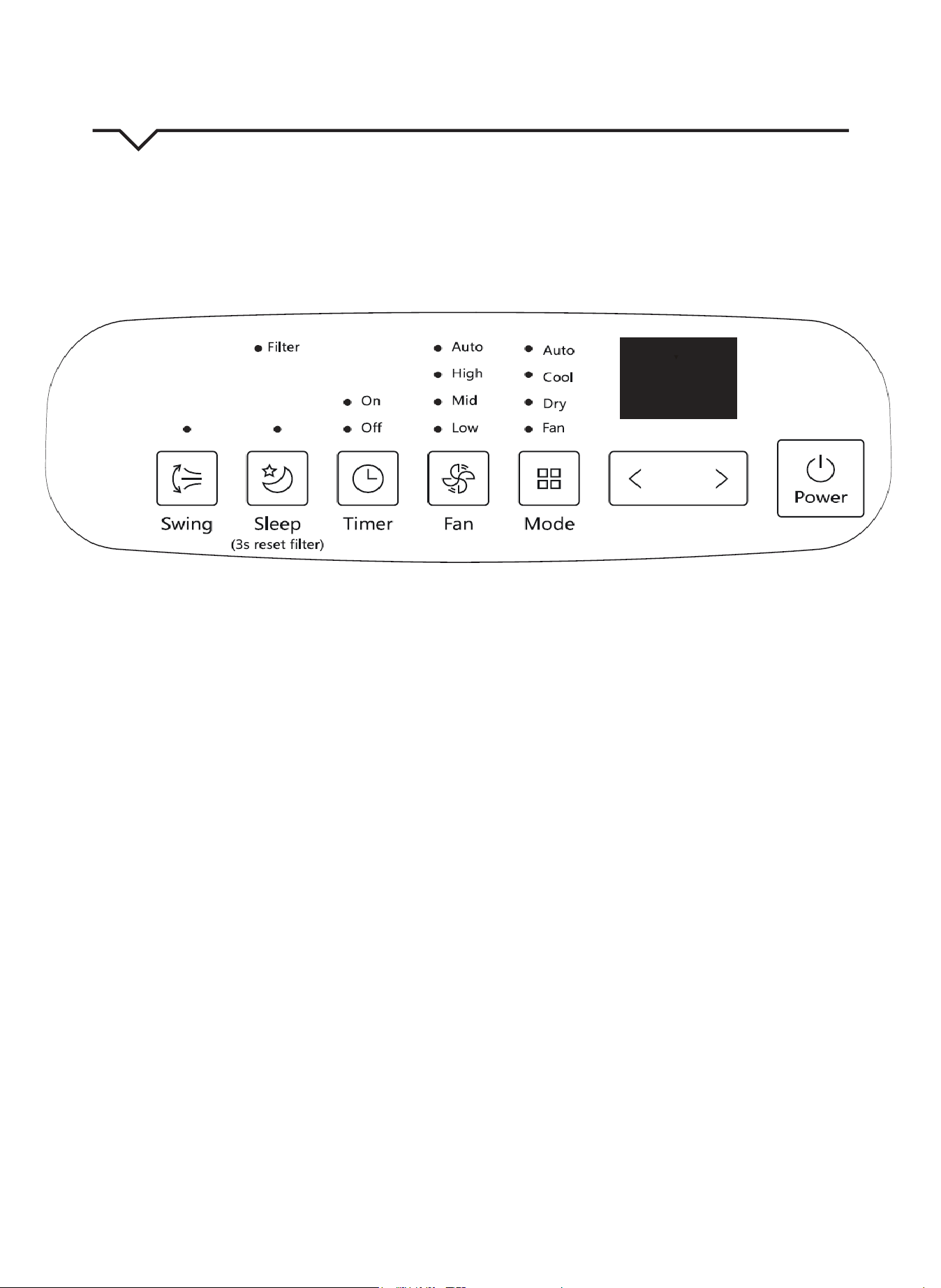
AIR CONDITIONER FEATURES
Thoroughly familiarize yourself with the control panel shown below and all of its functions. Afterwards, follow the symbol for the functions you
desire. This unit can be controlled by the unit control or the remote control.
NOTE: This manual does not include Remote Control Operations; see the Remote Control Instructions packed with the unit for details.
1. POWER button
Power switch ON/OFF.
2. DOWN (<) and UP (>) buttons
Used to adjust (increase/decrease) temperature
settings (1°F/1°C increments) in a range of 62°F
(17°C) to 86°F (30°C) or to set the TIMER setting in a
range of 0 – 24 hours.
NOTE: The control is capable of displaying the
temperature in degrees Fahrenheit or degrees
Celsius. To convert from one to the other, press and
hold the Up and Down buttons at the same time for
3 seconds.
3. MODE select button
Selects the appropriate operating mode. Each
time you press the button, a mode is selected in a
sequence that goes from AUTO, COOL, DRY and
FAN. The mode indicator light illuminates next to the
different mode settings.
4. FAN button
Control the fan speed. Press to select one of three
fan speeds: LOW, MID, HIGH or AUTO. The fan
speed indicator light illuminates next to the different
fan settings.
5. TIMER button
Used to initiate the AUTO ON start time and AUTO
OFF stop time program, in conjunction with the (<)
and (>) buttons. The timer ON/OFF indicator light
illuminates next to the timer ON/OFF settings.
6. SLEEP button/Filter Reset
Used to initiate the SLEEP operation.
NOTE: After 250 hours of operation, the lter indicator
light illuminates. This feature is a reminder to clean
the Air Filters for more ecient operation. Press and
hold the SLEEP button for 3 seconds to reset lter
reminder light.
7. LED display
Shows the set temperature in “°C” or “°F” and the
Auto-timer settings. While on DRY and FAN modes,
it shows the room temperature. (Details about error
codes that may appear on the display can be found
on page 13.)
8. FILTER indicator
NOTE: After 250 hours of operation, the lter indicator
light illuminates. This feature is a reminder to clean
the Air Filter for more ecient operation.
• Press and hold the FAN button for 3 seconds to
cancel the reminder.
• Press and hold the SLEEP button for 3 seconds to
reset lter reminder light.
9. Swing button
Used to initiate the Auto swing feature. When the
operation is ON, press the SWING button can stop
the louver at the desired angle.
FIG. 24
12
OPERATING INSTRUCTIONS
COOL mode
• Press the “MODE” button until the “COOL” indicator light
comes on.
• Press the “+” or “-” button to select your desired room
temperature. The temperature can be set within a range of
62°F~86°F/17°C~30°C.
• Press the “FAN SPEED” button on the remote control to
choose the fan speed.
DRY mode
• Press the “MODE” button until the “DRY” indicator light
comes on.
• Under this mode, you cannot select a fan speed or adjust the
temperature. The fan motor operates at LOW speed only.
• Keep windows and doors closed for the best dehumidifying
effect.
• Remove exhaust hose and slider when in this mode.
FAN mode
• Press the “MODE” button until the”FAN “ indicator light
illuminates.
• Press the “FAN SPEED” button on the remote control to
choose the fan speed. The temperature cannot be adjusted.
• Remove exhaust hose and slider, they are not needed in this
mode.
AUTO mode (On some models)
• When using AUTO mode, the unit will automatically
select cooling, heating, or fan only operation
depending on your selected temperature and the room
temperature.
• The air conditioner will control room temperature
automatically based on the temperature point set by
you.
• Under AUTO mode, you cannot select the fan speed.
NOTE: Under AUTO mode, both the AUTO mode
and operation mode indicator lights illuminate for
some models.
SLEEP
• When SLEEP mode is activated, the set temperature will
increase by 2°F(1°C) in 30 minutes.
• The set temperature will then increase by another 2°F(1°C)
after an additional 30 minutes.
• This new temperature will be maintained for 7 hours before
it returns to the originally selected temperature. This ends
the SLEEP mode and the unit will continue to operate as
originally programmed.
NOTE: This feature is unavailable under FAN or
DRY mode.
Auto-Restart
If the unit breaks off unexpectedly due to the power being cut, it
will automatically restart with the previous function setting when
the power resumes.
*WAIT 3 MINUTES BEFORE RESUMING
OPERATION. After the unit has stopped, operation
cannot be restarted in the rst 3 minutes. This is to
protect the unit. Operation will automatically start
after 3 minutes.
SWING BUTTON
• Used to initiate the Auto swing feature.
• While activated, press the SWING button again to stop the
louver at the desired angle.
TIMER OPERATION
• When the unit is ON, pressing the TIMER button will start the
Auto-off stop program.
• Press the UP or DOWN buttons to select the desired time
Auto-off.
• Press the TIMER button again within 5 seconds to start the
Auto-on start program.
• Press the UP or DOWN buttons to select the desired Auto-on
time.
• When the unit is OFF, press the TIMER button to initiate the
Auto-on start program
• Set the desired Auto-on start time and press TIMER again
within 5 second to initiate the Auto-off program.
• Set the desired Auto-off time.
• The control will count down the time remaining until start.
• The system will automatically revert back to displaying the
previous temperature setting if there is no operation in a 5
second period.
• Turning the unit ON or OFF at any time or adjusting the timer
setting to 0.0 will cancel the Auto Start/Stop timer program.
• When a malfunction occurs, the Auto Start/Stop program will
also be cancelled.
FOLLOW ME
This feature can ONLY be activated from the remote
control. The remote control serves as a remote
thermostat allowing for precise temperature control at
its location.

13
ERROR AND PROTECTION CODES
E1-RoomTemperatureSensorError-
Unplug the unit and plug it back in. If error
repeats, call Consumer Services.
E2-EvaporatorTemperatureSensorError-
Unplug the unit and plug it back in. If error
repeats, call Consumer Services.
E3-CondenserTemperatureSensorError-
Unplug the unit and plug it back in. If error
repeats, call Consumer Services.
E4-DisplayPanelCommunicationError-
Unplug the unit and plug it back in. If error
repeats, call Consumer Services.
EC-RefrigerantLeakageDetectionMalfunction-
Unplug the unit and plug it back in. If error
repeats, call Consumer Services.
E7-Zero-CrossingMalfunction-
Unplug the unit and plug it back in. If error
repeats, call Consumer Services.
P1-BottomTrayisFull-
Remove bottom drain plug and empty the
collectedwaterintoaoordrain,outdoors,
or into a shallow pan. Carefully tilt unit back
slightly to assist the water in draining. If error
does not clear after emptying, call
Consumer Services.

14
NOTE
Ahighlyrecommendedtroubleshootforanyissueingeneralconsistsofturningoffunitandunpluggingfor5minutes.Itisalso
recommended to try another wall outlet. For further assistance, contact Consumer Services.
TROUBLESHOOTING
BEFORE CALLING FOR SERVICE, PLEASE REVIEW THE CHART BELOW
ISSUE POSSIBLE CAUSES
AIR CONDITIONER NOT
COOLING ROOM, OR NOT
BLOWING COLD AIR
• Be sure unit is not too large or too small for the area of the room.
• Verify that all doors, windows, curtains and any other openings are closed.
Verify nothing is obstructing the front grille of unit, such as curtains, etc.
• Allow enough time for room to cool, especially if outside temp is very high.
•Checkthatthelterisnotdirtyandlouversareopenallthewayandblowinginthedesired
direction.
• Check that unit is set to COOL mode and that temperature is down enough (but not too low).
• If unit is near a heat source, such as a stove, etc., relocate unit.
• If air coming from unit is cool to the touch, then unit is working properly; please double check the
rstthreebulletpointsabove.
• Try using the Follow Me feature for more even cooling.
• If using Follow Me remote feature, move remote away from unit. (Ensure, however, that the remote
controliswithin20ftanda180°radiusofthefrontoftheunit.)
•Unplugunitforatleast5minutes.FollowResetinstructionsonplug.
AIR CONDITIONER COOLING
BUT ROOM IS TOO WARM -
ICE FORMING ON COOLING
COIL BEHIND DECORATIVE
FRONT
•Outdoortemperatureisbelow64ºF(18ºC).Todefrostthecoil,settoFAN
only mode.
•Airltermaybedirty.Cleanlter.RefertoCareandCleaningsection.Todefrost,settoFANonly
mode.
•Thermostatissettoocoldfornight-timecooling.Todefrostthecoil,settoFAN
only mode. Then, set temperature to a higher setting.
AIR CONDITIONER CYCLING
ON
AND OFF TOO FREQUENTLY
OR
NOT ENOUGH
• Be sure unit is not too large or too small for the area of the room.
• Make sure nothing is blocking the louvers.
•Makesurethereisnodirtordebrisinsidetheunitoronthelter.
• Try using the Follow Me feature for more even cooling.
UNIT WILL NOT TURN ON
• Reset circuit breaker. Make sure there are not too many items (i.e. lamps, TV’s, etc.) working off the
same breaker.s
• Check plug connection.
• If plug is operating on an on/off switch, be sure that the switch is ‘on’.
• Try plugging unit into another outlet.
•Unplugunitforatleast5minutes.FollowResetinstructionsonplug.
•CheckforP1errorcodeanddrainwaterfromWaterCollectionTray
UNIT BLOWS FUSES OR POPS
CIRCUIT BREAKER
• Make sure there are enough available amps on the circuit for the air conditioner.
•Largeunitswhichrunona230vwillrequireadedicated20or30ampcircuit.
AIR CONDITIONER IS
MAKING NOISES
• Check to be sure the unit is free from debris. Verify nothing is obstructing the unit.
• Check the fan blade for cracks or chips.
• Make sure the window slider kit is properly and securely mounted inside
the window.
•Cleantheairlter.
•Makesureunitisonaat,levelsurface.
REMOTE SENSING /
FOLLOW ME DEACTIVATING
PREMATURELY
•Remotecontrolnotlocatedwithinrange.Placeremotecontrolwithin20ftand180ºradiusofthe
front of the unit.
• Remote control signal obstructed. Remove obstruction.
• Replace batteries in remote control with a fresh set of batteries.
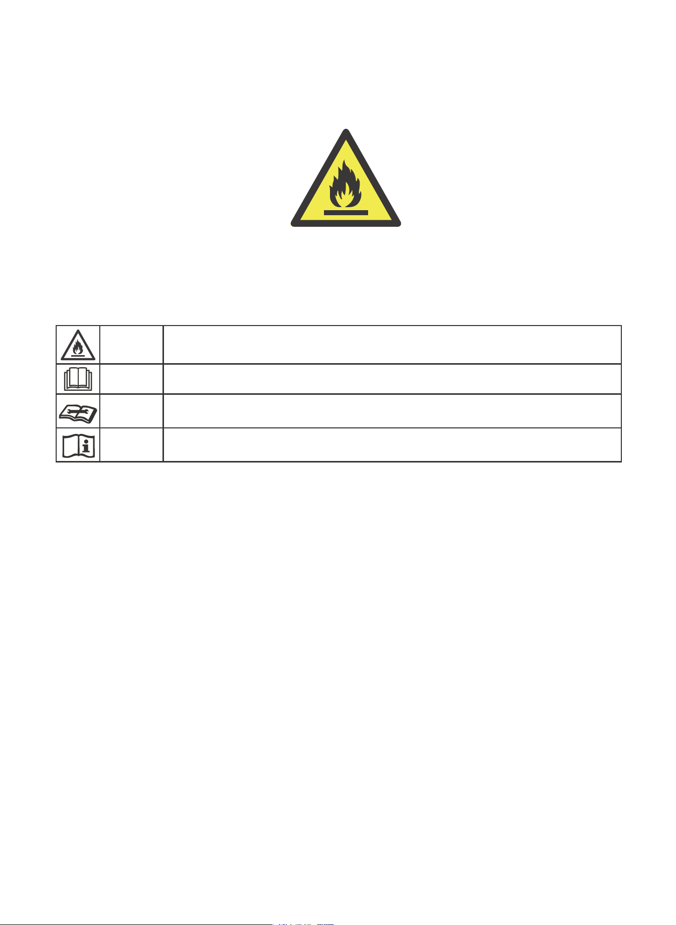
Caution: Risk of fire/
flammable materials
(Required for R32/R290 units only)
Explanation of symbols displayed on the unit(For units with R32/R290 Refrigerant only):
WARNING
This symbol shows that this appliance used a flammable refrigerant. If the refrigerant is leaked
and exposed to an external ignition source, there is a risk of fire.
CAUTION
This symbol shows that the operation manual should be read carefully.
CAUTION
This symbol shows that a service personnel should be handling this equipment with reference to
the installation manual.
CAUTION
This symbol shows that information is available such as the operating manual or installation
manual.


844-4PA-AIRE | 844-472-2473
www.perfectaire.us
Perfect Aire, LLC
5401 Dansher Road
Countryside, IL 60625
Printed in China
1020_M393
MODEL
2PORT12000
2PORT14000