®
ELECTRONIC 7-DAY
WATER HEATER TIME SWITCHES
MODELS EH10, 120 V AND EH40, 240 V
WITH BATTERY CARRYOVER
OWNER/INSTALLER INSTRUCTION MANUAL
RETAIN FOR FUTURE REFERENCE.
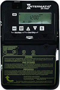
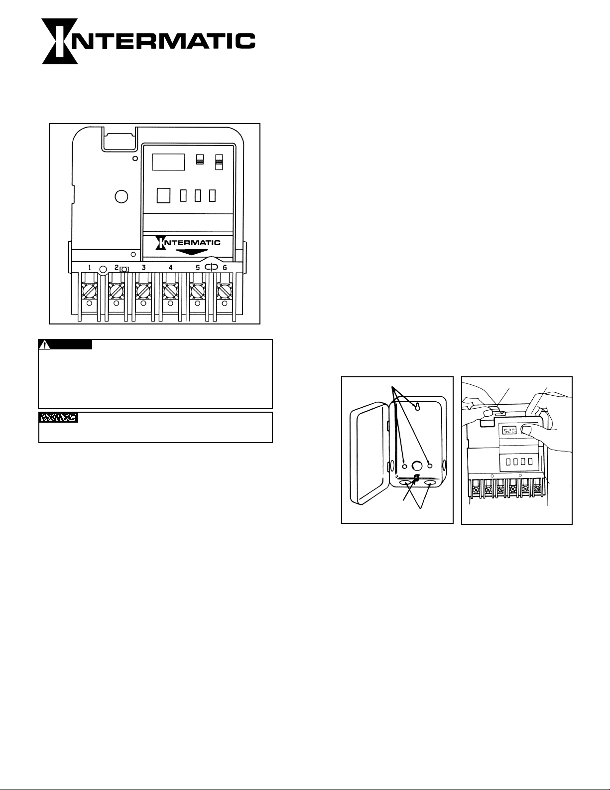
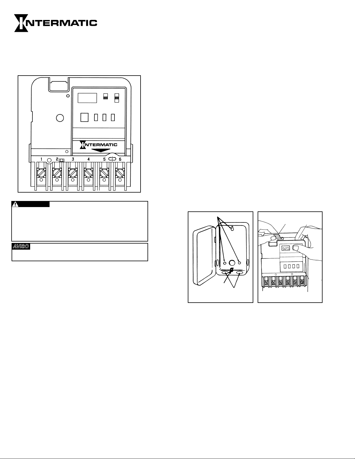
MANUAL (MAN) - AUTOMATIC (AUTO)
(See Fig. 1)
• MANUAL: Bypasses your program completely; timer
will not resume program until you return switch to
AUTO mode position.
• AUTOMATIC: For automatically switching at ON/OFF
times; accurate to-the-minute.
PROGRAM (PROG) - RUN - TIME SET
• PROGRAM: Use this position when programming.
• RUN: Use this position for normal operation. Be sure to
return to RUN after setting time and program.
• TIME SET: Use this position to set day and time of day.
ON/OFF - EVENT (the large push button) - Serves a
dual purpose
• EVENT: Used for programming (active only when switch
is set at PROG).
• ON/OFF: Override (active only when switch is set at
RUN); turns load ON if already off or OFF if already on.
Timer automatically resumes program cycle only when
slide switch is in AUTO. Note that this button is also
accessible without opening the enclosure.
SPECIFICATIONS:
Clock Voltage - Model EH40 - 240 VAC, 50/60 Hz
EH10 - 120 VAC, 50/60 Hz
Power Consumption - EH10 - 1.0 W Max., EH40 - 3.0
W Max.
Contact Configuration - EH10 (SPST) Single pole-single
throw model- EH40(DPST) Double pole-single throw model
MAN
AUTO
PROG
RUN
TIME
SET
ON
OFF
EVENT
DAY
HOUR
MIN
LOAD
RESET
BATTERY
®
Fig.1
Set Points (Events) - 12 total (6 ON/6 OFF) - Can be
assigned in any combination to weekdays, weekend days,
daily or weekly operation providing up to a maximum of 84
weekly operations (42 ON/42 OFF).
Battery Powered Clock Operation - 3 years minimum,
AA industrial grade alkaline supplied with time switch.
Minimum ON/OFF Time - 1 minute
Maximum ON/OFF Time - 6 days 23 hours 59 minutes
Shipping Weight - 2.37 lbs. (1.05 kg)
Case - Drawn steel, 7-3/4" (19.7 cm) high, 5" (12.7 cm)
wide, 3" (7.6 cm) deep; gray finish with lockable spring
hasp, clear see-through viewing window and external
override.
Knockouts - Combination of 1/2” - 3/4” (one on back and
each side, two on bottom)
Wire Size - AWG #10.
GENERAL SAFETY INFORMATION:
1. Mount the time switch in the desired location using the
three mounting holes which are provided. Mount the
time switch at eye level, if possible, providing sufficient
room to the left of the enclosure for the cover to swing
open fully. (See Fig. #2). The time switch mechanism
does not need to be removed from the enclosure to
mount the time switch since the top mounting hole is
a slotted type mounting hole. Secure a screw or other
fastener at eye level. The head of the screw of fastener
should be slightly larger than the narrow portion of the
slotted hole to ensure that the time switch is securely
held in place. The remaining two mounting holes
provide a means to secure the time switch.
2. If you do remove the mechanism, refer to Figure #3 and
remove the mechanism from the case by depressing
the catch at the top of the case and pulling out.
Fig. 3
Fig. 2
Mounting Holes
Knockouts
Ground
Terminal
Snap Out Catch
Tilt Top Forward
Lift Up
To
Remove
3. Replace the mechanism in the case if it has been
removed, making sure to engage ribs at sides of
mechanism between ears at sides of case before
snapping in place.
4. Lift the left side of the insulator off of the retaining
post and pivot it up and away to expose the terminal
screws.
5. Strip the supply and load wires by removing 1/2 inch
of insulation. DO NOT USE ALUMINUM WIRE. Insert
the wire ends under the proper terminal plates and
tighten the screws firmly. Use any size wire AWG #10.
Connect ground wire to grounding terminal at bottom
of case.
6. Replace the plastic insulator.
7. Follow instructions for battery installation. Be sure
that the battery is functioning properly. This can be
checked by seeing that the display is visible. If the
display has scrambled information, check to be sure
that the polarity orientation of the battery is as shown
on the cover label, then press the RESET switch and
hold for at least two seconds. Note that the battery
can easily be replaced without removing the time
switch mechanism or field wiring. Simply press in and
downward (in the direction of the arrow) on the battery
cover which is identified with the word “Battery”.
It is recommended that the battery be replaced with
a “AA” industrial grade alkaline cell at two to three
Switch Rating (Per Pole) -
• 30 A inductive/resistive - 120-240 VAC, 60 Hz
• 1 HP, 120 VAC, 60 Hz.
• 1-1/2 HP, 240 VAC, 60 Hz.
• 5 A tungsten, 120-240 VAC, 60 Hz.
Risk of Fire or Electric Shock
• Disconnect power at the circuit breaker(s) or disconnect switch(es) before installing
or servicing.
• More than one circuit breaker or disconnect switch may be required to de-energize
the equipment before servicing.
• Installation and/or wiring must be in accordance with National and Local Electrical
Code requirements.
• Use #10 AWG wires - COPPER conductors ONLY.
NOTICE
• Do not touch circuit board components; contact can create a static discharge, which
can damage the microprocessor.
WARNING
year intervals as part of the normal time switch maintenance
observing battery polarity markings when installing. No
other maintenance is required.
8. Place the slide switches in the AUTO and RUN position.
9. Reapply power to the time switch.
10. Press the recessed reset switch for at least two seconds.
The display will show 12:00 A.M. and MO. Note that the
days of the week are identified with the first two letters
of the day (MO for Monday). The timer is now ready for
programming. Refer to the examples which follow and
enter the scheduled events (set points) required. Assign
each of the 12 set points (EVENTS) entered to whichever
day or groups of days of the week you wish an ON or OFF
operation to occur.
Set Point = Event = ON = OFF
PROGRAMMING STEPS:
SET CURRENT DAY AND TIME
Slide switch to TIME SET. Push DAY until current day
shows, then push HOUR until current hour AM or PM
shows. Now push MINUTE until current minute shows.
Clock is now set. Follow same procedure after replacing
battery or changing time (such as for daylight saving time).
SET YOUR PROGRAM
Slide switch to PROG. Display will look like this: (-:- -)
• Press DAY until desired program period shows (see
choices in “PROGRAM PERIOD OPTIONS” section above).
• Press HOUR until desired “ON 1” hour shows
(that is, the first time each day of the program
period that you want the load to turn ON).
• Press MINUTE until desired minute shows.
• Press EVENT to program time for ON 1
(and to advance to programming for OFF 1).
• Press DAY again until all seven days of the
week show (or until another desired program
period option shows; see “PROGRAM PERIOD
OPTIONS”).
• Press HOUR again until desired “OFF 1” hour shows
(that is, the first time each day of the program
period that you want the devices to turn OFF).
• Press MINUTE until desired minute shows.
• Press EVENT to set time for OFF 1. You may now begin
setting ON 2, a second ON time, for the same program
period, OR press DAY to change to a different program
period.
• Repeat above procedure until all desired ON/OFF
programs are set.
PLEASE NOTE: Before you program your timer, or when you
remove the battery, or when you use the RESET, pressing
EVENT will display the bar symbol -:-- ON 1. Repeated
pressing of EVENT will display all the way through the final bar
symbol -:-- OFF 6. Once you program your timer, however,
each actual time setting you make will replace the bar symbol.
While programming, each time you press EVENT you will
advance to the next EVENT.
PROGRAM PERIOD OPTIONS:
Your timer gives you up to 6 different ON and 6 different OFF
settings per program period. You can use all 6 settings per
period, or as few as you like. A program period covers one of
these:
• ALL 7 DAYS OF THE WEEK combined into one - display
shows: MO TU WE TH FR SA SU.
• MONDAY THRU FRIDAY combined into one -
display shows: MO TU WE TH FR.
• SATURDAY AND SUNDAY combined into one -
display shows: SA SU.
• EACH INDIVIDUAL DAY OF THE WEEK -
display shows only that day.
• BLANKDAY EXPLANATION - “BLANKDAY”
follows Sunday after last push of DAY button (when
the lower slide switch is set at PROGRAM). The
purpose of the BLANKDAY is to disable a program
setting on a day.
Program periods with days “combined into one” help
you make settings for those multiple days quickly and
conveniently while using only one ON/OFF pair. When you
set such a program period, all settings will be identical for
every day of that period.
PERSONAL PROGRAM EXAMPLES
EVENTS
DAY CHECKS ON TIMES OFF TIMES DISPLAYED DAYS & TIMES DISPLAYED
EXAMPLE 1
MO TU WE TH FR SA SU 5:00 PM 10:00 PM ON 1 MO TU WE TH FR SA SU 5:00 PM
OFF 1 MO TU WE TH FR SA SU 10:00 PM
EXAMPLE 2
MO TU WE TH FR 6:00 PM 10:00 PM ON 1 MO TU WE TH FR 6:00 PM
OFF 1 MO TU WE TH FR 10:00 PM
SA SU 4:00 PM 8:00 PM ON 2 SA SU 4:00 PM
OFF 2 SA SU 8:00 PM
EXAMPLE 3
MO TU WE TH FR 6:00 AM 9:30 AM ON 1 MO TU WE TH FR 6:00 AM
OFF 1 MO TU WE TH FR 9:30 AM
MO TU WE TH FR 5:30 PM 11:15 PM ON 2 MO TU WE TH FR 5:30 PM
OFF 2 MO TU WE TH FR 11:15 PM
SA SU 3:00 PM 10:00 PM ON 3 SA SU 3:00 PM
OFF 3 SA SU 10:00 PM
NOTE: “-:- -” follows Sunday after last push of DAY button
(when the slide switch is set at PROG). The purpose of the
-:- - is to cancel a program setting on that day.
REVIEW YOUR PROGRAM
Slide switch to PROG. Press EVENT button to advance
display to each ON or OFF setting. Check days and times
displayed. To make a change, follow instructions under
“SET YOUR PROGRAM”. To delete a displayed set point,
press DAY button until “-:- -” is displayed.
GENERAL FEATURES AND HINTS FOR TROUBLE
FREE USE
• BUTTON: When you press a button, there is an advance
of one time unit; holding a button down advances
continuously until released.
• MAINTENANCE: With the exception of battery
replacement at 2-3 year intervals, your Intermatic timer
is maintenance-free.
• AFTER THE INSTALLATION IS COMPLETED, THE
LOCKABLE HASP SHOULD BE MOVED TO THE UP
POSITION TO ENGAGE THE COVER WHEN IT IS
CLOSED.
LIMITED ONE-YEAR WARRANTY
If within the warranty period specified, this product fails due to a defect in material or
workmanship, Intermatic Incorporated will repair or replace it, at its sole option, free of
charge. This warranty is extended to the original household purchaser only and is not
transferable. This warranty does not apply to: (a) damage to units caused by accident,
dropping or abuse in handling, acts of God or any negligent use; (b) units which have been
subject to unauthorized repair, opened, taken apart or otherwise modified; (c) units not used
in accordance with instructions; (d) damages exceeding the cost of the product; (e) sealed
lamps and/or lamp bulbs, LED’s and batteries; (f) the finish on any portion of the product,
such as surface and/or weathering, as this is considered normal wear and tear; (g) transit
damage, initial installation costs, removal costs, or reinstallation costs.
INTERMATIC INCORPORATED WILL NOT BE LIABLE FOR INCIDENTAL OR
CONSEQUENTIAL DAMAGES. SOME STATES DO NOT ALLOW THE EXCLUSION
OR LIMITATION OF INCIDENTAL OR CONSEQUENTIAL DAMAGES, SO THE ABOVE
LIMITATION OR EXCLUSION MAY NOT APPLY TO YOU. THIS WARRANTY IS IN LIEU
OF ALL OTHER EXPRESS OR IMPLIED WARRANTIES. ALL IMPLIED WARRANTIES,
INCLUDING THE WARRANTY OF MERCHANTABILITY AND THE WARRANTY OF FITNESS
FOR A PARTICULAR PURPOSE, ARE HEREBY MODIFIED TO EXIST ONLY AS CONTAINED
IN THIS LIMITED WARRANTY, AND SHALL BE OF THE SAME DURATION AS THE
WARRANTY PERIOD STATED ABOVE. SOME STATES DO NOT ALLOW LIMITATIONS ON
THE DURATION OF AN IMPLIED WARRANTY, SO THE ABOVE LIMITATION MAY NOT
APPLY TO YOU.
This warranty service is available by either (a) returning the product to the dealer from
whom the unit was purchased or (b) completing a warranty claim online at www.
intermatic.com. This warranty is made by: Intermatic Incorporated, Customer Service
7777 Winn Rd., Spring Grove, Illinois 60081-9698. For warranty service go to:
http://www.intermatic.com or call 815-675-7000.
INTERMATIC INCORPORATED
SPRING GROVE, ILLINOIS 60081-9698
- 2 -
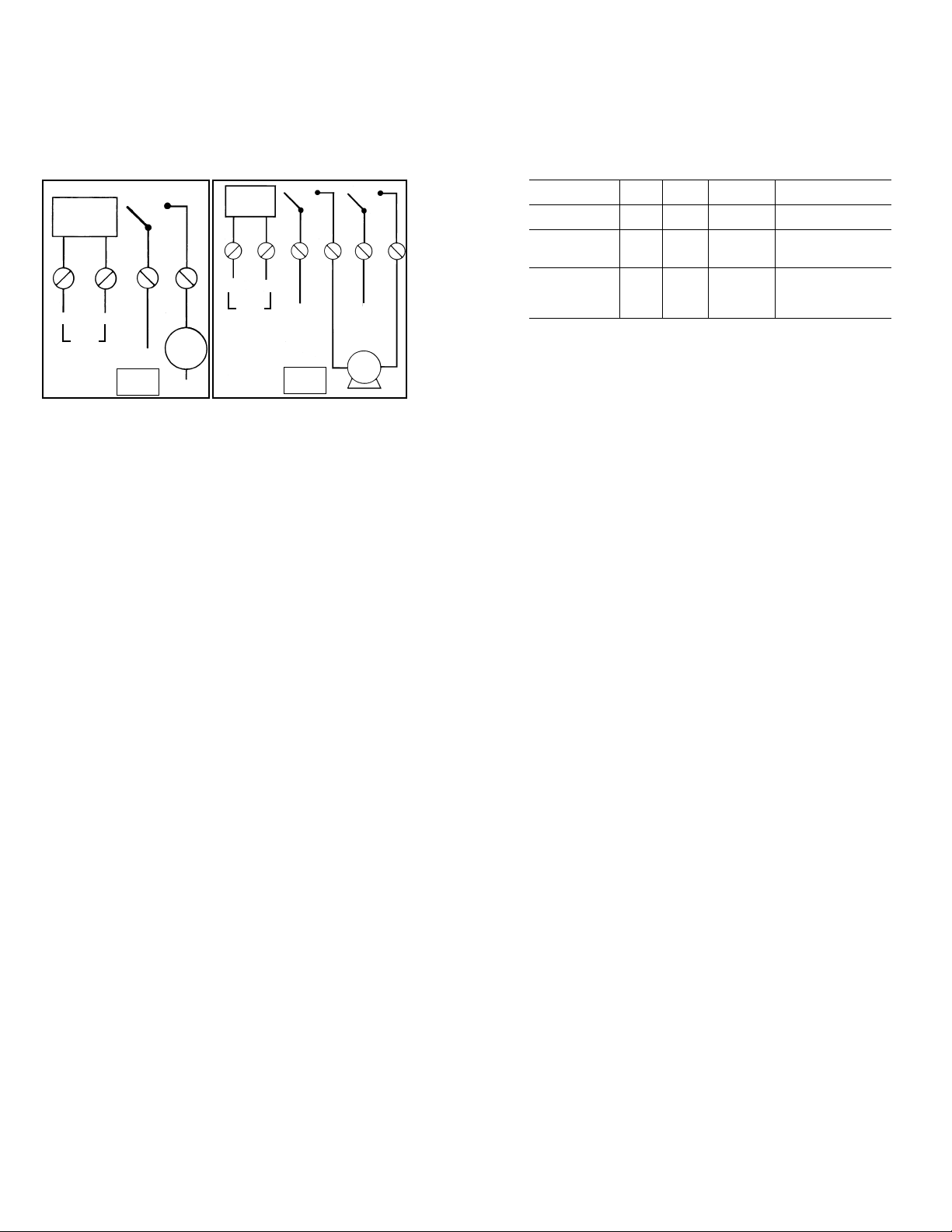
TIMER
POWER
LOAD
NEUTRAL
NEUTRAL
1
2 3 4
Fig. 4
Fig. 5
TIMER
POWER
1
2 3
4
5 6
LINE 1
LINE
LINE
LINE 2
LINE 1
LINE 2
LOAD
120 ≈
240≈
EH10
EH40
®
- 3 -
MINUTERIES ÉLECTRONIQUES POUR
CHAUFFE-EAU 7 JOURS
MODÈLES EH10, 120V ET EH40, 240V
AVEC BASCULEMENT SUR PILES
MANUEL D’INSTRUCTION DE L’UTILISATEUR/
INSTALLATEUR
À CONSERVER POUR RÉFÉRENCE ULTÉRIEURE.
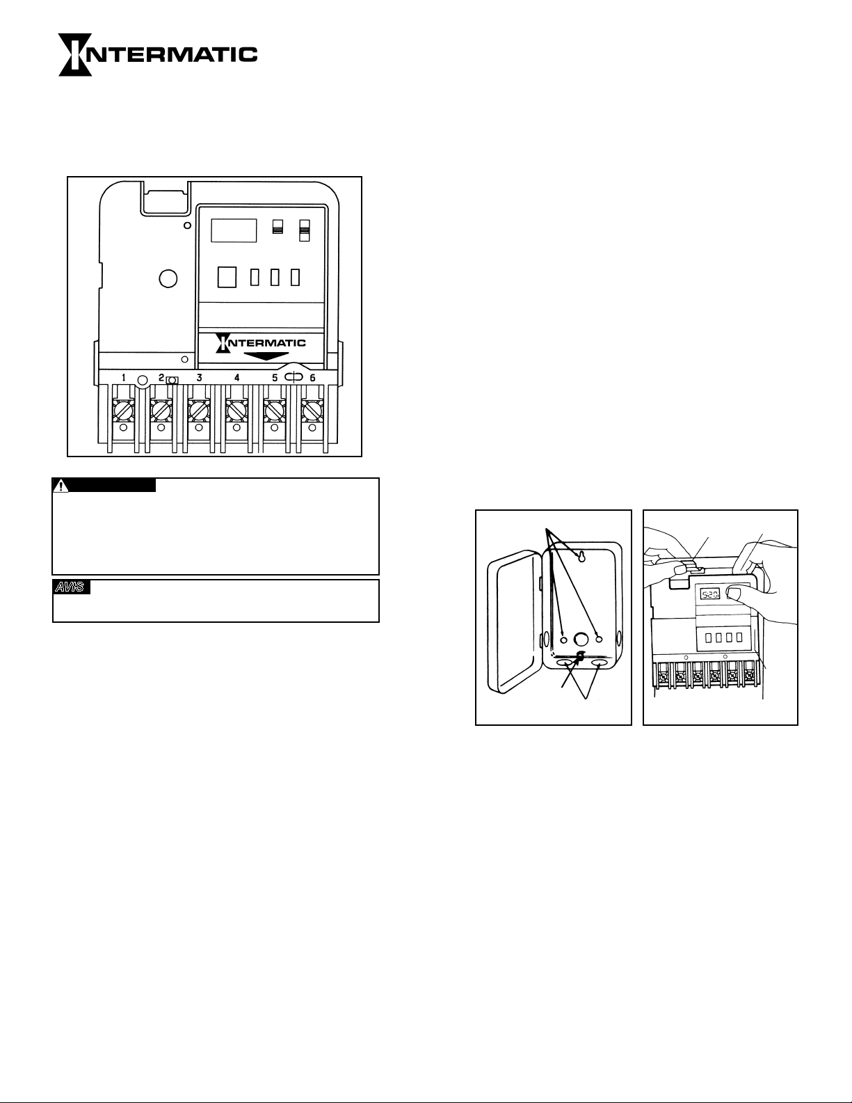
MANUEL (MAN) - AUTOMATIQUE (AUTO)
(Voir Fig. 1)
• MANUEL : Ignore complètement le programme ; la minuterie ne
reprend le programme que lorsque le commutateur est remis en
position AUTO.
• AUTOMATIQUE: Commutation automatique aux temps ON/OFF
programmés; précis à la minute près.
PROGRAMME (PROG) - RUN - TIME SET
• PROGRAMME: Utiliser cette position pour la programmation.
• RUN : Utiliser cette position pour la marche normale. Veiller à
bien revenir en position RUN après le réglage de l’heure ou la
programmation.
• TIME SET: Utiliser cette position pour régler le jour et l’heure de la
journée.
ON/OFF - EVENT (le grand bouton poussoir) - Remplit deux
fonctions
• EVENT : Utilisé pour la programmation (actif uniquement si le
commutateur est en position PROG).
• ON/OFF: Priorité manuelle (active uniquement si le commutateur
est en position RUN); met le circuit sous tension (ON) s’il est coupé
ou hors tension (OFF) s’il est en marche. La minuterie reprend
automatiquement le cycle programmé uniquement si le sélecteur
est en position AUTO. On notera que ce bouton est accessible sans
ouvrir le boîtier.
DONNÉES TECHNIQUES:
Tension de l’horloge - Modèle EH40 - 240V CA, 50/60 Hz
EH10 - 120 V CA, 50/60 Hz
Consommation électrique - EH10 - 1,0 W max, EH40 - 3,0 W max
Configuration des contacts - EH10 unipolaire unidirectionnel (SPST)
- EH40 bipolaire unidirectionnel (DPST)
MAN
AUTO
PROG
RUN
TIME
SET
ON
OFF
EVENT
DAY
HOUR
MIN
LOAD
RESET
BATTERY
®
Fig. 1
Points de consigne (événements) - 12 au total (6 ON/6 OFF) -
Assignables dans toute combinaison aux jours de semaine, jours
de fin de semaine, chaque jour ou une fois par semaine, offrant
jusqu’à un maximum de 84 actions par semaine (42 ON/42 OFF).
Fonctionnement de l’horloge sur piles - 3 ans minimum, pile
alcaline AA de qualité industrielle fournie avec la minuterie.
Durée ON/OFF minimale - 1 minute
Durée ON/OFF maximale - 6 jours 23 heures 59 minutes
Poids d’expédition - 1,05kg (2,37 lb)
Boîtier - Acier étiré, hauteur 19,7 cm (7-3/4po), largeur 12,7 cm
(5 po), profondeur 7,6 cm (3 po) ; finition grise avec fermoir à
ressort verrouillable, hublot transparent et commande manuelle
externe.
Alvéoles défonçables - Combinées de 1/2 - 3/4po (une au dos
et sur chaque côté, deux au fond)
Calibre des fils - N°10 AWG.
INFORMATIONS GÉNÉRALES DE SÉCURITÉ :
1. Monter la minuterie à l’emplacement souhaité par les trois
trous de fixation prévus à cet effet. Monter la minuterie
à hauteur des yeux, si possible, en prévoyant un espace
suffisant sur la gauche du boîtier pour ouvrir complètement
le couvercle (voir Fig. 2). Il n’est pas nécessaire de démonter
le mécanisme de minuterie du boîtier pour permettre la pose
dans la mesure où le trou de fixation du haut est de type trou
en poire. Poser une vis ou autre attache de fixation à hauteur
des yeux. La tête de la vis ou de l’attache doit être légèrement
plus grande que la partie étroite du trou en poire afin d’assurer
que la minuterie soit solidement tenue en place. Les deux trous
de fixation restants servent à fixer la minuterie en place.
2. Le cas échéant, le mécanisme peut être démonté en appuyant
sur le taquet en haut du boîtier et en tirant le mécanisme hors
du boîtier (voir Fig. 3).
Fig. 3
Fig. 2
Trous de fixation
Alvéoles
défonçables
Borne de terre
Dégager le
taquet
Incliner le haut
vers l’avant
Soulever
pour
retirer
3. Remettre le mécanisme en place dans le boîtier s’il a été
démonté, en veillant à bien engager les nervures sur les côtés
du mécanisme entre les pattes sur les côtés du boîtier avant
de l’encliqueter en place.
4. Détacher le côté gauche du couvre-bornes de la barrette de
retenue et le faire pivoter pour exposer les vis du bornier.
5. Dénuder les fils d’alimentation et de charge sur 13 mm
(1/2 po). NE PAS UTILISER DE FIL D’ALUMINIUM. Enfiler
le bout des fils sous la plaquette de contact des bornes
correspondantes et serrer fermement les vis. Utiliser tout
calibre de fil, n° 10 AWG. Raccorder le fil de terre à la borne
de terre au bas du boîtier.
6. Remettre le couvre-bornes en plastique en place.
7. Suivre les instructions de mise en place de la pile. S’assurer
que la pile fonctionne correctement. Pour cela, vérifier que
l’affichage est visible. Si l’écran présente un affichage brouillé,
vérifier que la pile est orientée conformément à la polarité
indiquée sur le couvercle, puis tenir le bouton RESET enfoncé
pendant au moins deux secondes. On notera que la pile est
facile à changer sans démonter le mécanisme de minuterie ni
le câblage. Il suffit d’appuyer sur le couvercle de pile, marqué
« Battery », et de le pousser vers le bas (dans le sens de
la flèche). Il est recommandé de remplacer la pile par une
pile alcaline AA de qualité industrielle tous les deux ou trois
ans dans le cadre de l’entretien normal de la minuterie, en
respectant les marquages de polarité lors de la mise en place
de la pile. Aucun autre entretien n’est nécessaire.
Caractéristiques des interrupteurs (par pôle) -
• 30 A inductif/résistif - 120-240 V CA, 60 Hz
• 1 HP 120 V CA, 60 Hz
• 1-1/2 HP 240 V CA, 60 Hz
• 5 A tungstène, 120-240 V CA, 60 Hz
Risque d’incendie ou de choc électrique
• Débrancher l’alimentation au niveau des disjoncteurs ou des sectionneurs avant
de procéder à l’installation ou à l’entretien.
• Il peut être nécessaire d’ouvrir plusieurs disjoncteurs ou sectionneurs pour mettre
le matériel hors tension avant d’y travailler.
• L’installation et/ou le câblage doivent être conformes aux exigences du code de
l’électricité en vigueur.
• Utiliser des fils n°10 AWG - Conducteurs en CUIVRE UNIQUEMENT.
AVIS
• Ne pas toucher les composants du circuit imprimé, le contact peut provoquer une
décharge d’électricité statique susceptible d’endommager le microprocesseur.
AVERTISSEMENT
• FONCTION DE JOUR BLANC - Un «JOUR BLANC» suit
le dimanche (SU) lorsqu’on appuie sur le bouton DAY (avec
le commutateur en position PROG). L’objet du jour blanc
est de désactiver la programmation durant un jour.
Les périodes de programmation ayant des jours « combinés »
permettent une programmation rapide et pratique sur de multiples
jours tout en n’utilisant qu’une seule paire ON/OFF. Lorsqu’une
telle période de programmation est choisie, tous les réglages sont
identiques pour chaque jour de cette période.
EXEMPLES DE PROGRAMMATION
JOURS CHOISIS
ÉVÉNEMENTS
HEURESON HEURESOFF AFFICHAGE JOURS ET HEURES AFFICHÉS
EXEMPLE 1
MO TU WE TH FR SA SU 5:00 PM 10:00 PM ON 1 MO TU WE TH FR SA SU 5:00 PM
OFF 1 MO TU WE TH FR SA SU 10:00 PM
EXEMPLE 2
MO TU WE TH FR 6:00 PM 10:00 PM ON 1 MO TU WE TH FR 6:00 PM
OFF 1 MO TU WE TH FR 10:00 PM
SA SU 4:00 PM 8:00 PM ON 2 SA SU 4:00 PM
OFF 2 SA SU 8:00 PM
EXEMPLE 3
MO TU WE TH FR 6:00 AM 9:30 AM ON 1 MO TU WE TH FR 6:00 AM
OFF 1 MO TU WE TH FR 9:30 AM
MO TU WE TH FR 5:30 PM 11:15 PM ON 2 MO TU WE TH FR 5:30 PM
OFF 2 MO TU WE TH FR 11:15 PM
SA SU 3:00 PM 10:00 PM ON 3 SA SU 3:00 PM
OFF 3 SA SU 10:00 PM
REMARQUE: L’affichage «-:- -» suit le dimanche (SU) lorsqu’on
appuie sur le bouton DAY (avec le commutateur en position
PROG). L’objet du jour blanc est d’annuler un réglage de
programmation pour ce jour.
PASSER LE PROGRAMME EN REVUE
Mettre le commutateur en position PROG. Appuyer sur le bouton
EVENT pour faire défiler chaque réglage ON ou OFF. Vérifier les
jours et heures affichés. Pour effectuer une modification, suivre
les instructions de la section «RÉGLER LE PROGRAMME». Pour
supprimer un point de consigne affiché, appuyer sur le bouton
DAY jusqu’à afficher «-:- -».
FONCTIONNALITÉS GÉNÉRALES ET CONSEILS
D’UTILISATION
• BOUTONS : Lorsqu’on appuie sur un bouton, la valeur de
temps affichée avance d’une unité ; tenir le bouton enfoncé
pour avancer en continu jusqu’à ce qu’il soit relâché.
• ENTRETIEN: À l’exception du remplacement de la pile tous les
2 à 3 ans, la minuterie Intermatic est sans entretien.
• UNE FOIS L’INSTALLATION TERMINÉE, LE FERMOIR
VERROUILLABLE DOIT ÊTRE EN POSITION HAUTE POUR
S’ENGAGER SUR LE COUVERCLE LORSQUE CELUI-CI EST
FERMÉ.
GARANTIE LIMITÉE UN AN
Si, durant la période de garantie indiquée, ce produit présente un défaut de matériau ou
de fabrication, Intermatic Incorporated s’engage à le réparer ou à le remplacer, à sa seule
discrétion, sans frais. La présente garantie s’étend à l’acheteur particulier initial uniquement
et n’est pas transférable. Cette garantie ne s’applique pas : (a) aux dommages au dispositif
causés par un accident, une chute ou une mauvaise manipulation, une catastrophe naturelle
ou une utilisation négligente; (b) aux dispositifs soumis à des réparations non autorisées,
qui ont été ouverts, démontés ou modifiés de quelconque manière; (c) aux dispositifs qui
n’ont pas été utilisés conformément aux instructions; (d) aux dommages dépassant le coût
du produit; (e) aux lampes scellées et/ou aux ampoules, aux LED et aux piles; (f) à la finition
de l’une des parties du dispositif, telle que la surface ou les caractéristiques de résistance
aux intempéries, ce qui est considéré comme de l’usure normale; (g) aux dommages causés
par le transport, aux coûts d’installation initiale, aux coûts de démontage ou de remontage.
INTERMATIC INCORPORATED NE POURRA ÊTRE TENUE RESPONSABLE DE DOMMAGES
INDIRECTS OU CONSÉCUTIFS. CERTAINES JURIDICTIONS N’AUTORISENT PAS L’EXCLUSION
OU LA LIMITATION DES DOMMAGES INDIRECTS OU CONSÉCUTIFS. DANS CE CAS, LES
LIMITES CI-DESSUS NE S’APPLIQUENT PAS. LA PRÉSENTE GARANTIE REMPLACE TOUTES
LES AUTRES GARANTIES EXPRESSES OU IMPLICITES. TOUTES LES GARANTIES IMPLICITES,
NOTAMMENT GARANTIE DE QUALITÉ MARCHANDE ET GARANTIE D’ADAPTATION À UNE FIN
PARTICULIÈRE, SONT MODIFIÉES AUX PRÉSENTES POUR EXISTER UNIQUEMENT TELLES
QUE COMPRISES DANS LA GARANTIE LIMITÉE, ET AURONT LA MÊME DURÉE QUE LA
PÉRIODE DE GARANTIE INDIQUÉE CI-DESSUS. CERTAINES JURIDICTIONS N’AUTORISENT
PAS LES LIMITES DE DURÉE D’UNE GARANTIE IMPLICITE. DANS CE CAS, LES LIMITES CI-
DESSUS NE S’APPLIQUENT PAS.
Le recours à la présente garantie se fait soit (a) par renvoi du produit au vendeur
auprès duquel il a été acheté, soit (b) en remplissant le formulaire de réclamation
sur le site Web www.intermatic.com. La présente garantie est offerte par : Intermatic
Incorporated, Customer Service 7777 Winn Rd., Spring Grove, Illinois 60081-9698. Pour
recourir à la garantie, aller à: http://www.intermatic.com ou composer le 815-675-
7000.
INTERMATIC INCORPORATED
SPRING GROVE, ILLINOIS 60081-9698
- 4 -
8. Placer les sélecteurs en position AUTO et RUN.
9. Remettre la minuterie sous tension.
10. Appuyer sur l’interrupteur encastré RESET pendant au moins deux
secondes. L’écran affiche alors 12:00 A.M. et MO. On notera que
les jours de la semaine sont identifiés par les deux premières lettres
de leur nom en anglais (MO pour lundi [Monday]). La minuterie
est à présent prête pour la programmation. En se référant aux
exemples qui suivent, entrer les événements programmés (points
de consigne) souhaités. Assigner chacun des 12 points de consigne
(événements) entrés au jour ou groupe de jours de la semaine
auxquels un action ON ou OFF doit se produire.
Point de consigne = Événement = ON = OFF
PROGRAMMATION :
RÉGLER LE JOUR ET L’HEURE COURANTS
Mettre le commutateur en position TIME SET. Appuyer sur DAY
jusqu’à afficher le jour courant, puis sur HOUR jusqu’à afficher
l’heure courante, y compris AM ou PM. Appuyer ensuite sur
MINUTE jusqu’à afficher les minutes courantes. L’horloge est à
présent réglée. Suivre la même procédure après avoir changé
la pile ou pour changer l’heure (passage à l’heure d’été, par
exemple).
RÉGLER LE PROGRAMME
Mettre le commutateur en position PROG. L’affiche a l’aspect suivant:
(-:- -)
• Appuyer sur DAY jusqu’à afficher la période de programmation
souhaitée (voir les choix dans la section «CHOIX DE PÉRIODES
DE PROGRAMMATION»).
• Appuyer sur HOUR jusqu’à afficher l’heure ON 1 souhaitée
(c.-à-d. l’heure de la première mise sous tension du circuit de
charge, chaque jour de la période de programmation).
• Appuyer sur MINUTE jusqu’à afficher les minutes souhaitées.
• Appuyer sur EVENT pour valider l’heure de programmation de
ON 1 (et passer à la programmation de OFF 1).
• Appuyer de nouveau sur DAY jusqu’à afficher les sept jours de
la semaine (ou une autre période de programmation souhaitée,
voir «CHOIX DE PÉRIODES DE PROGRAMMATION»).
• Appuyer de nouveau sur HOUR jusqu’à afficher l’heure OFF 1
souhaitée (c.-à-d. l’heure de la première mise hors tension du
circuit de charge, chaque jour de la période de programmation).
• Appuyer sur MINUTE jusqu’à afficher les minutes souhaitées.
• Appuyer sur EVENT pour valider l’heure OFF 1. À présent,
une deuxième heure de mise sous tension, ON 2, peut être
programmée, SOIT pour la même période de programmation,
SOIT pour une période de programmation différente choisie en
appuyant sur DAY.
• Répéter la procédure ci-dessus jusqu’à ce que tous les
événements ON/OFF souhaités soient programmés.
REMARQUE: Avant la programmation de la minuterie ou lorsque la
pile est retirée ou encore après utilisation du bouton RESET, lorsqu’on
appuie sur EVENT, l’écran affiche -:-- ON 1. Une pression répétée sur
le bouton EVENT fait défiler l’affichage jusqu’à -:-- OFF 6. Une fois
que la minuterie est programmée, les réglages d’heure s’affichent à la
place des tirets. Durant la programmation, chaque fois qu’on appuie
sur EVENT, la minuterie passe à l’événement suivant.
CHOIX DE PÉRIODES DE PROGRAMMATION:
La minuterie offre jusqu’à 6 réglages ON et 6 réglages OFF différents
par période de programmation. Il est possible d’utiliser les 6 réglages,
ou moins, dans une même période. Les périodes de programmation
possibles sont les suivantes:
• LES 7 JOURS DE LA SEMAINE combinés - l’écran affiche: MO
TU WE TH FR SA SU.
• DU LUNDI AU VENDREDI combinés - l’écran affiche: MO TU
WE TH FR.
• SAMEDI ET DIMANCHE combinés - l’écran affiche: SA SU.
• UN JOUR INDIVIDUEL DE LA SEMAINE - l’écran affiche
uniquement le jour considéré.
ALIMENTATION
MINUTERIE
CHARGE
NEUTRE
NEUTRE
1
2 3 4
Fig. 4
Fig. 5
ALIMENTATION
MINUTERIE
1
2 3
4
5 6
PHASE 1
PHASE
PHASE
PHASE 2
PHASE 1
PHASE 2
CHARGE
120
240
EH10
EH40
- 5 -
INTERRUPTORES TEMPORIZADORES
ELECTRÓNICOS DE 7 DÍAS PARA
CALENTADORES DE AGUA
MODELOS EH10,120 V Y EH40, 240 V
CON TRASPASO DE BATERÍA
MANUAL DE INSTRUCCIONES PARA EL PROPIETARIO O
INSTALADOR
CONSERVE PARA CONSULTA FUTURA.
MAN (MANUAL) - AUTO (AUTOMÁTICO)
(Consulte la Fig. 1)
• MAN: Omite el programa completamente; el temporizador no
continuará con el programa hasta que vuelva a colocar el interruptor
en la posición del modo AUTOMÁTICO.
• AUTO: Para realizar conmutación automática en las horas de
ENCENDIDO y APAGADO con precisión.
PROG (PROGRAMA) - RUN (EJECUCIÓN) - TIME SET
(AJUSTE DE HORA)
• PROG: Use esta posición cuando realice la programación.
• RUN: Use esta posición para el funcionamiento normal. Asegúrese
de volver a RUN después de ajustar la hora y el programa.
• TIME SET: Use esta posición para ajustar la fecha y la hora del día.
ON/OFF - EVENT (Encendido/apagado - Evento) (El botón
pulsador grande); sirve para un propósito doble
• EVENT: Se usa para programar (solo activo cuando el interruptor
se ajusta en PROG).
• ON/OFF: Transferencia de mando (activo solo cuando el interruptor
se ajusta en RUN); ENCIENDE la carga si ya está apagada o la
APAGA si ya está encendida. El temporizador automáticamente
continúa con el ciclo de programa solo cuando el interruptor
deslizante está en AUTO. Tenga presente que también se puede
acceder a este botón sin abrir la caja.
ESPECIFICACIONES:
Voltaje del reloj: Modelo EH40 - 240 V CA, 50/60 Hz
EH10 - 120 V CA, 50/60 Hz
Consumo de energía: EH10 - 1,0 W máx., EH40 - 3,0 W máx.
Configuración de contactos: EH10 (SPST) Modelo unipolar de una
vía; EH40 (DPST) Modelo bipolar de una vía
MAN
AUTO
PROG
RUN
TIME
SET
ON
OFF
EVENT
DAY
HOUR
MIN
LOAD
RESET
BATTERY
®
Fig.1
Puntos de ajuste (Eventos): 12 en total (6 ENCENDIDO/6 APAGADO);
sepuede asignar en cualquier combinación de días de semana, días
de fin de semana, funcionamiento diario o semanal, con lo que brinda
hasta un máximo de 84 operaciones semanales (42 ENCENDIDO/
42APAGADO).
Funcionamiento del reloj accionado por batería: 3 años mínimo,
batería alcalina industrial AA proporcionada con el interruptor
temporizador.
Tiempo de ENCENDIDO/APAGADO mínimo: 1 minuto
Tiempo de ENCENDIDO/APAGADO máximo: 6 días, 23 horas,
59minutos
Peso de envío: 1,05 kg
Caja: Acero estirado, 19,7 cm de alto, 12,7 cm de ancho, 7,6 cm de
profundidad; acabado gris con ranura para cerradura con resorte,
ventana de visualización transparente y transferencia de mando
externa.
Orificios ciegos: Combinación de tamaño de 1/2” a 3/4” (uno en la
parte posterior y a cada lado, dos en la parte inferior)
Tamaño del cable: AWG n.º 10.
INFORMACIÓN GENERAL DE SEGURIDAD:
1. Monte el interruptor temporizador en la ubicación deseada con los
tres orificios de montaje que se proporcionan. Monte el interruptor
temporizador al nivel de sus ojos, si es posible, y proporcione
suficiente espacio hacia la izquierda de la caja para que la cubierta
se abra completamente. (Consulte Fig. 2). No es necesario retirar el
mecanismo del interruptor temporizador de la caja para montarlo,
ya que el orificio de montaje superior es un orificio de montaje de
tipo ovalado. Fije un tornillo u otro sujetador al nivel de los ojos. La
cabeza del tornillo o el sujetador debe ser levemente más grande
que la parte angosta del orificio ovalado para garantizar que el
interruptor temporizador quede bien sujeto. Los dos orificios de
montaje restantes brindan la posibilidad de fijar el interruptor
temporizador.
2. Si desea retirar el mecanismo, consulte Figura 3, presione el retén
en la parte superior de la caja y tire del mecanismo hacia afuera
para retirarlo.
3. Vuelva a colocar el mecanismo en la caja si lo ha retirado,
y asegúrese de enganchar las ranuras de los costados del
mecanismo entre los bordes ondulados de los costados de la caja
antes de encajarlo en su lugar.
4. Levante el lado izquierdo del aislamiento para sacarlo del borne
de retención y gírelo hacia arriba y hacia afuera para exponer la
regleta de terminales.
5. Quite 12,7 mm de aislamiento a los cables de alimentación y
carga. NO USE CABLES DE ALUMINIO. Inserte los extremos
de los cables en las placas de terminal adecuadas y apriete
los tornillos firmemente. Use un cable AWG n.º 10 de cualquier
tamaño. Conecte el cable a tierra en el terminal de conexión a
tierra en la parte inferior de la caja.
6. Vuelva a colocar el aislamiento plástico.
7. Siga las instrucciones para la instalación de la batería. Asegúrese
de que la batería esté funcionando adecuadamente. Para esto,
revise que la pantalla esté visible. Si la pantalla tiene información
revuelta, compruebe que la orientación de la polaridad de la
batería esté como se muestra en la etiqueta de la cubierta, luego
presione el interruptor RESET (Restablecimiento) y manténgalo
presionado durante al menos dos segundos. Tenga en cuenta
que la batería se puede reemplazar fácilmente sin retirar el
mecanismo del interruptor temporizador o el cableado de campo.
Simplemente presione la cubierta de la batería, identificada con
la palabra “Battery” (Batería) hacia adentro y hacia abajo (en la
dirección de la flecha). Se recomienda que la batería se reemplace
con una batería de celda alcalina industrial “AA” en intervalos
de dos a tres años, como parte del mantenimiento normal del
interruptor temporizador y que observe las marcas de polaridad
de la batería cuando la instale. No se requiere mantenimiento
adicional.
Clasificaciones del interruptor (por polo):
• 30 A inductivo/resistivo: 120 a 240 V CA, 60 Hz
• 1 HP, 120 V CA, 60 Hz.
• 1-1/2 HP, 240 V CA, 60 Hz.
• 5 A tungsteno, 120 a 240 V CA, 60 Hz.
Riesgo de incendio o descarga eléctrica
• Desconecte la energía desde los disyuntores o desde los interruptores antes de
realizar la instalación o el mantenimiento.
• Es posible que requiera más de un disyuntor o interruptor de desconexión para
desenergizar el equipo antes de realizar mantenimiento.
• La instalación o el cableado se deben realizar de acuerdo con los requisitos del
Código Eléctrico Nacional y los requisitos locales.
• Use cables AWG n.º 10; SOLO conductores de COBRE.
AVISO
• No toque los componentes del tablero de circuitos; el contacto puede provocar una
descarga estática, lo que puede dañar el microprocesador.
ADVERTENCIA
Fig. 3
Fig. 2
Orificios de montaje
Orificios
ciegos
Terminal de
conexión a tierra
Incline la parte
superior hacia
adelante
Levante
para
retirar
Retén de desencaje
a presión
®
- 6 -
8. Coloque los interruptores deslizantes en la posición AUTO y RUN.
9. Vuelva a aplicar energía al interruptor temporizador.
10. Presione el interruptor de restablecimiento empotrado durante al menos
dos segundos. La pantalla mostrará 12:00 A.M. y MO. Tenga en cuenta
que los días de la semana se identifican con las primeras dos letras
del día en inglés (MO para lunes [Monday]). El temporizador está listo
para la programación. Consulte los ejemplos a continuación e ingrese
los eventos programados (puntos de ajuste) necesarios. Asigne cada
uno de los 12 puntos de ajuste (EVENTOS) ingresados a cualquier día o
grupo de días de la semana en los que desea que ocurra una operación
de ENCENDIDO o APAGADO.
Punto de ajuste = Evento = ENCENDIDO = APAGADO
PASOS PARA PROGRAMAR:
AJUSTE EL DÍA Y LA HORA ACTUALES
Deslice el interruptor a TIME SET. Presione DAY (Día) hasta que se
muestre el día actual, luego presione HOUR (Hora) hasta que se
muestre la hora actual a. m. o p. m. Ahora, presione MINUTE (Minuto)
hasta que se muestren los minutos actuales. Ahora, el reloj está
ajustado. Siga el mismo procedimiento después de reemplazar la
batería o cambiar la hora (por ejemplo, para el horario de verano).
AJUSTE SU PROGRAMA
Deslice el interruptor a PROG. La pantalla se verá así: (-:- -)
• Presione DAY hasta que se muestre el período de programa deseado
(consulte las opciones en la sección “OPCIONES DEL PERÍODO DE
PROGRAMACIÓN” mencionada posteriormente).
• Presione HOUR hasta que se muestre la hora “ON 1” (Encendido
1) deseada (es decir, la primera vez de cada día del período del
programa que quiere que se ENCIENDA la carga).
• Presione MINUTE hasta que se muestre el minuto deseado.
• Presione EVENT (Evento) para programar la hora del ON 1 (y para
avanzar hacia la programación del OFF 1 [Apagado 1]).
• Presione DAY nuevamente hasta que se muestren todos los días
de la semana (o hasta que se muestre otra opción de período
de programa deseado; consulte “OPCIONES DE PERÍODO DE
PROGRAMA”).
• Presione HOUR nuevamente hasta que se muestre la hora “OFF
1” deseada (es decir, la primera vez de cada día del período del
programa donde quiere que se APAGUEN los dispositivos).
• Presione MINUTE hasta que se muestre el minuto deseado.
• Presione EVENT para ajustar la hora de OFF 1. Ahora, puede
comenzar el ajuste de ON 2, una segunda hora de ENCENDIDO,
para el mismo período de programa, O BIEN, presione DAY para
cambiar a un período de programa diferente.
• Repita el procedimiento anterior hasta que se ajusten todos los
programas de ENCENDIDO/APAGADO deseados.
TENGA EN CUENTA: Antes de programar el temporizador, cuando retire
la batería, o bien, cuando use el RESTABLECIMIENTO, si presiona EVENT
mostrará el símbolo de barra -:-- ON 1. Si presiona EVENT repetidamente,
se mostrará hasta el final del símbolo de barra -:-- OFF 6. Sin embargo,
una vez que programe el temporizador, cada ajuste de hora real que haga
reemplazará al símbolo de barra. Mientras programa, cada vez que presione
EVENT avanzará al siguiente EVENTO.
OPCIONES DE PERÍODO DE PROGRAMA:
El temporizador le da 6 ajustes diferentes de ENCENDIDO y de APAGADO
por período de programa. Puede usar todos los 6 ajustes por período, o
los que usted desee. Un período de programa cubre uno de los siguientes:
• LOS 7 DÍAS DE LA SEMANA combinados en uno, la pantalla
muestra: MO TU WE TH FR SA SU (LU MA MI JU VI SA DO).
• LUNES A VIERNES combinados en uno, la pantalla muestra: MO TU
WE TH FR (LU MA MI JU VI).
• SÁBADO Y DOMINGO combinados en uno, la pantalla muestra: SA
SU (SA DO).
• CADA DÍA INDIVIDUAL DE LA SEMANA; la pantalla solo muestra
ese día.
ENERGÍA DEL
TEMPORIZADOR
CARGA
NEUTRO
NEUTRO
1
2 3 4
Fig. 4
Fig. 5
ENERGÍA DEL
TEMPORIZADOR
1
2 3
4
5 6
LÍNEA 1
LÍNEA
LÍNEA
LÍNEA 2
LÍNEA 1
LÍNEA 2
CARGA
120
240
EH10
EH40
• EXPLICACIÓN DE DÍA EN BLANCO Aparece “BLANKDAY”
(Día en blanco) después del domingo, después de apretar el
botón DAY por última vez (cuando el interruptor deslizante
inferior está en PROG). El fin del DÍA EN BLANCO es
desactivar un ajuste de programa en un día.
Los períodos de programa con días “combinados en uno” le permiten
realizar ajustes para aquellos días múltiples de manera rápida y
cómoda, mientras usa solo un par de ENCENDIDO/APAGADO.
Cuando ajuste algún período de programa como el anterior, todos los
ajustes serán idénticos para cada día de dicho período.
EJEMPLOS DE PROGRAMAS PERSONALES
DÍAS SELECCIONADOS
EVENTOS
HORAS DE
ENCENDIDO
HORAS DE
APAGADO SE MUESTRA DÍAS Y HORAS QUE SE MUESTRAN
EJEMPLO 1
MO TU WE TH FR SA SU 5:00 PM 10:00 PM ON 1 MO TU WE TH FR SA SU 5:00 PM
OFF 1 MO TU WE TH FR SA SU 10:00 PM
EJEMPLO 2
MO TU WE TH FR 6:00 PM 10:00 PM ON 1 MO TU WE TH FR 6:00 PM
OFF 1 MO TU WE TH FR 10:00 PM
SA SU 4:00 PM 8:00 PM ON 2 SA SU 4:00 PM
OFF 2 SA SU 8:00 PM
EJEMPLO 3
MO TU WE TH FR 6:00 AM 9:30 AM ON 1 MO TU WE TH FR 6:00 AM
OFF 1 MO TU WE TH FR 9:30 AM
MO TU WE TH FR 5:30 PM 11:15 PM ON 2 MO TU WE TH FR 5:30 PM
OFF 2 MO TU WE TH FR 11:15 PM
SA SU 3:00 PM 10:00 PM ON 3 SA SU 3:00 PM
OFF 3 SA SU 10:00 PM
NOTA: “-:- -” aparece después del domingo, después de apretar el
botón DAY por última vez (cuando el interruptor deslizante está en
PROG). El propósito de -:- - es cancelar un ajuste de programa en
tal día.
REVISE SU PROGRAMA
Deslice el interruptor a PROG. Presione el botón EVENT para avanzar
en la pantalla a cada ajuste de ENCENDIDO o APAGADO. Revise los
días y las horas que se muestran. Para realizar un cambio, siga las
instrucciones en “AJUSTE SU PROGRAMA”. Para borrar un punto de
ajuste que se muestra, presione el botón DAY hasta que se muestre
“-:- -”.
CARACTERÍSTICAS GENERALES Y SUGERENCIAS PARA UN
USO SIN PROBLEMAS
• BOTÓN: Cuando presione un botón, se produce un avance
de una unidad de tiempo; si lo mantiene presionado, avanzará
continuamente hasta que se suelte.
• MANTENIMIENTO: Con la excepción del reemplazo de la batería
en intervalos de 2 a 3 años, el temporizador Intermatic no necesita
mantenimiento.
• DESPUÉS DE COMPLETAR LA INSTALACIÓN, LA RANURA
PARA CERRADURA DEBE MOVERSE HACIA ARRIBA PARA
ENGANCHAR LA CUBIERTA CUANDO ESTÉ CERRADA.
GARANTÍA LIMITADA DE UN AÑO
Si dentro del período de garantía especificado, este producto presenta fallas a causa de
defectos en los materiales o en la mano de obra, Intermatic Incorporated lo reparará o lo
reemplazará, a su exclusivo criterio, sin cargo. Esta garantía se extiende solo al comprador
doméstico original y no es transferible. Esta garantía no se aplica a: (a) daño a las unidades
causado por accidente, caída o manipulación indebida, casos fortuitos o cualquier uso
negligente; (b) unidades que hayan sido reparadas, abiertas, desmontadas o modificadas
de otra forma sin autorización; (c) unidades que no se hayan usado de acuerdo con las
instrucciones; (d) daños que excedan el costo del producto; (e) focos o bombillas, LED
y baterías sellados; (f) el acabado de cualquier parte del producto, como la superficie o
la alteración por exposición a la intemperie, puesto que se considera como desgaste
natural; (g) daño en el transporte, costos de instalación inicial, costos de retiro o costos de
reinstalación.
INTERMATIC INCORPORATED NO SERÁ RESPONSABLE DE DAÑOS INCIDENTALES
O INDIRECTOS. ALGUNOS ESTADOS NO PERMITEN LA EXCLUSIÓN O LIMITACIÓN DE
DAÑOS INCIDENTALES O INDIRECTOS, DE MODO QUE LA LIMITACIÓN O EXCLUSIÓN
ANTERIOR PODRÍA NO APLICARSE A SU CASO. ESTA GARANTÍA REEMPLAZA
TODAS LAS DEMÁS GARANTÍAS EXPRESAS O IMPLÍCITAS. TODAS LAS GARANTÍAS
IMPLÍCITAS, INCLUIDA LA GARANTÍA DE COMERCIABILIDAD Y LA GARANTÍA DE
IDONEIDAD DEL PRODUCTO PARA UN PROPÓSITO EN PARTICULAR, POR MEDIO DEL
PRESENTE QUEDAN MODIFICADAS PARA TENER VALIDEZ SOLO COMO SE INDICA
EN ESTA GARANTÍA LIMITADA Y TENDRÁN LA MISMA DURACIÓN QUE EL PERÍODO
DE GARANTÍA ESTIPULADO ANTERIORMENTE. ALGUNOS ESTADOS NO PERMITEN
LIMITACIONES A LA DURACIÓN DE UNA GARANTÍA IMPLÍCITA, DE MODO QUE LA
LIMITACIÓN ANTERIOR PODRÍA NO APLICARSE A SU CASO.
Este servicio de garantía está disponible ya sea (a) si se devuelve el producto al
proveedor donde se compró la unidad; o (b) si se completa una reclamación de garantía
en línea en www.intermatic.com. Esta garantía la otorga: Intermatic Incorporated,
Customer Service 7777 Winn Rd., Spring Grove, Illinois 60081-9698. Para obtener servicios
de garantía, ingrese a: http://www.Intermatic.com o llame al 815-675-7000.
INTERMATIC INCORPORATED
SPRING GROVE, ILLINOIS 60081-9698
- 7 -
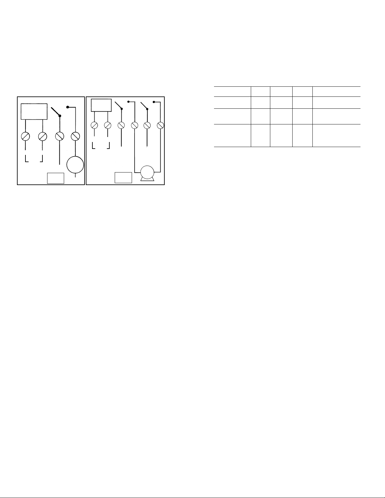
NOTE: Jumpers can be added to supply load power for 120 V loads, see Fig. 4. For 240 V loads See Fig. 5.
CAUTION: Do not use jumpers if load(s) are not 120 or 240 VAC, because the load can be damaged. Supply separate
power of the correct voltage.
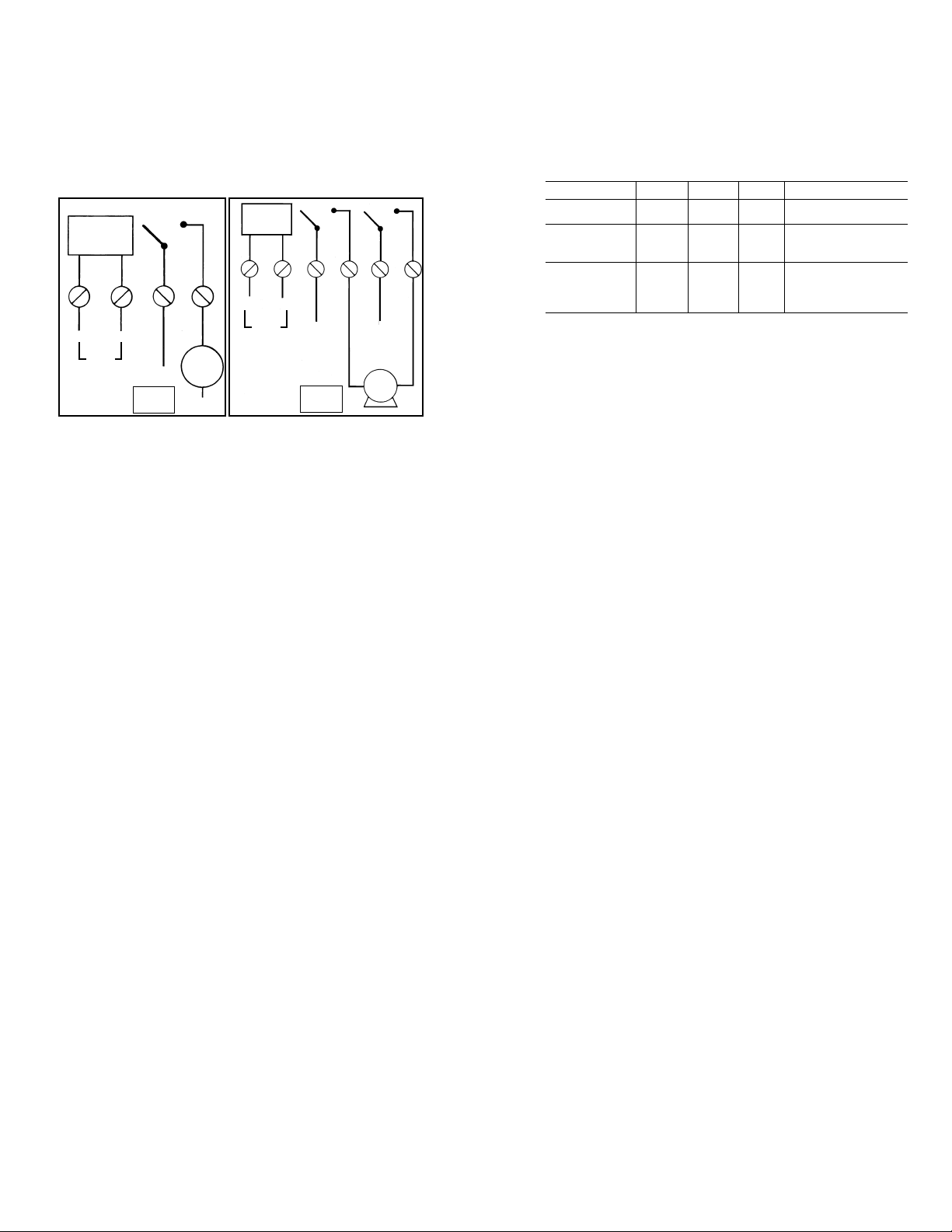
REMARQUE - Il ise possible d’introduire des cavaliers pour alimenter la charge. Pour les charges de 120V voir Fig.4.
Pour Les charges de 240 V voir Fig. 5. AVERTISSEMENT: Ne pas utiliser de cavaliers si la ou les charges ne sont pas
de 120 ou 240V, car la chare PEUT s’en trouver endommagé. Fournir une limentation séparée sous tension correcte.
NOTA: Los puentes de conexion pueden anadirse para suministrar alimentacion a la carga. Para cargas de 120V ver
Fig. 4. Para Cargas de 240 V ver Fig.5. ATENCION: No utilice los puentes de conexión si la(s) carga(s) no son de 120
o 240V porque la carga puede dañarse. Suministrar alimentación por separado con la tensión adecuada.
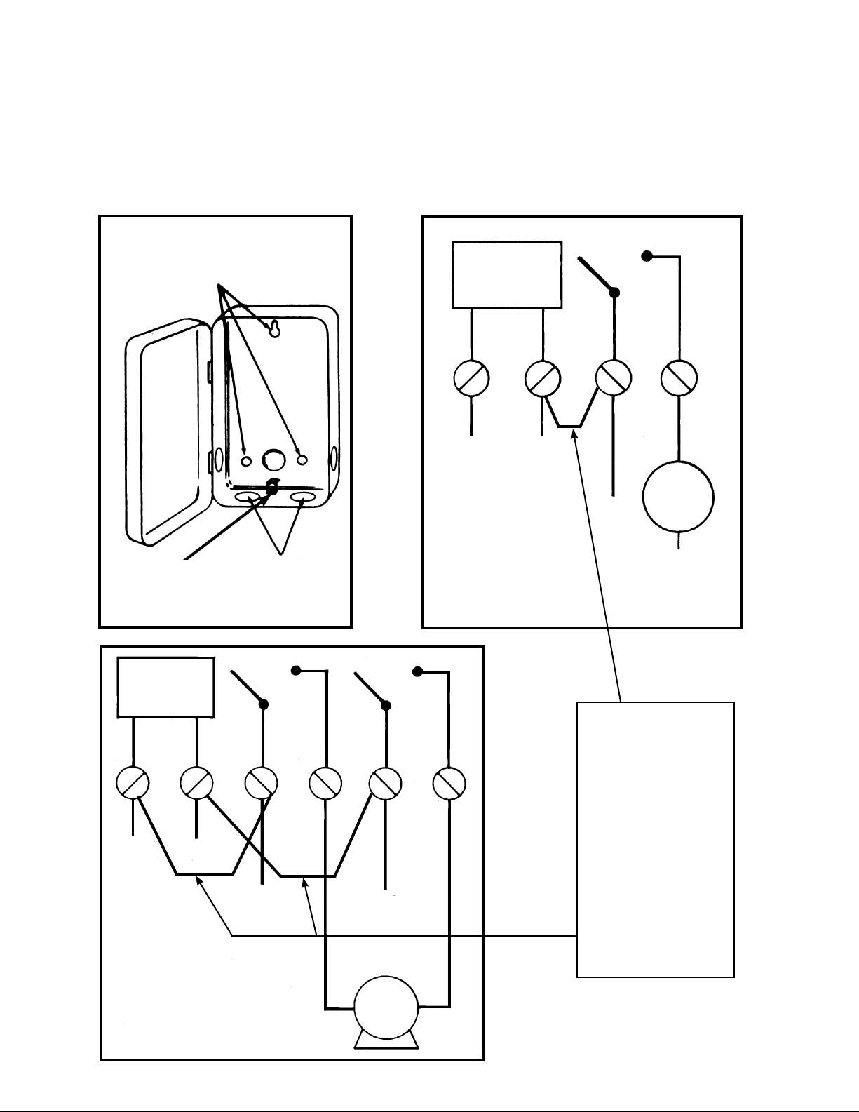
Trous de montage
(Agujeros para montar)
Débouchures
(Agujeros Ciegos)
Mise à la terre
(Terminal a tierra)
Fig. 2
ALIMENTATION
MINUTTERIE
ALIMENTACION
DEL
TEMPORIZADOR
1
2 3 4 5 6
CHARGE
CARGA
Pour interrompre les deux
cótés d’une charge de 240 V.
(Para cortar un lado de una
carga de 240 voltios.)
LIGNE 1
(LINEA 1)
LIGNE 2
(LINEA 2)
LIGNE 1
(LINEA 1)
LIGNE 2
(LINEA 2)
Fig. 5
CHARGE
CARGA
NEUTRE
(NEUTRAL)
LIGNE
(LINEA)
1 2 3 4
ALIMENTATION
MINUTERIE
ALIMENTACION
DEL
TEMPORIZADOR
NEUTRE
(NEUTRAL)
LIGNE
(LINEA)
Pour interrompre un cóté
d’une charge de 120 V.
(Para cortar un lado de una
carga de 120 voltios.)
Fig. 4
NOTA: Sólo para cargas de 120
voltios yo que la tensión del tempo-
rizador ees de 120 VCA, los puentes
de conexión pueden añadirse entr
las terminales 2 y 3 para suminis-
trar alimentaci´ón a la carga.
ATENCION: No utilice los puentes
de conexión si la(s) carga(s) no
son de 120 voltios porque la carga
puede dañarse.
Suministrar alimentación por sepa-
rado con la tensión adecuada.
Install jumper only if
timer input and load
voltage are the same.
Use solid wire with
solid wire and strand-
ed wire with stranded
wire.
Utiliser fil massif avec
fil massif et fil toronné
avec fil toronné. Ne
pas mélanger.
“Utilice cable solido
con cable solido y
cable trenzado con
cable trenzado, no los
combine”.

- 8 -
INTERMATIC INCORPORATED
SPRING GROVE, ILLINOIS 60081-9698
158--02004