Owners
Manual
FOR POTABLEWATER
HEATING ONLY
NOT SUITABLEFOR
SPACEHEATING
Model No.
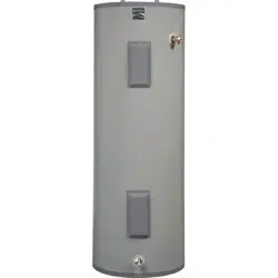
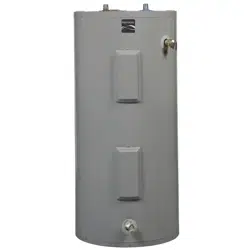
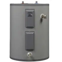
153.316152 30 GaLShort
153.316153 30 Gal. Short
153.316252 40 Gal. Short
153.316253 40 Gal. Short
153.316354 30 Gal.
153.316355 30 Gal.
153.316454 40 Gal.
153.316455 40 Gal.
I$3.316554 50 Gal.
153.316555 50 Gal.
153.316654 SOGal. Medium
153.316655 50 Gal. Medium
153.316754 40 Gal. Medium
153.316755 40 Gal. Medium
POWER MISERrM6
ELECTRIC
WATER HEATER
• Safety Instructions
• Installation
• Operation
• Care and Maintenance
• Troubleshooting
• Parts List
Caution:
Read and Follow
All Safety Rules and
Operating Instructions
Before First Use of
This Product.
Save this Manual for Future Reference.
GAMA certificationappliesto allresidential electric water heaters with
capacitiesof 20 to 120Gallons. Input rating of 12Kw or lessat avoltage
no greater than 250 V.
_WARNING I
READ THE GENERAL SAFETY SECTION BEGINNING ON INSIDE COVER
ANDINGTHIsTHENwATERTHISHEATER.ENTIREMANUAL BEFORE NSTALLING OR OPERAT-
Sears, Roebuck and Co., Hoffman Estates, IL 60179 U.S.A.
Safety Precautions
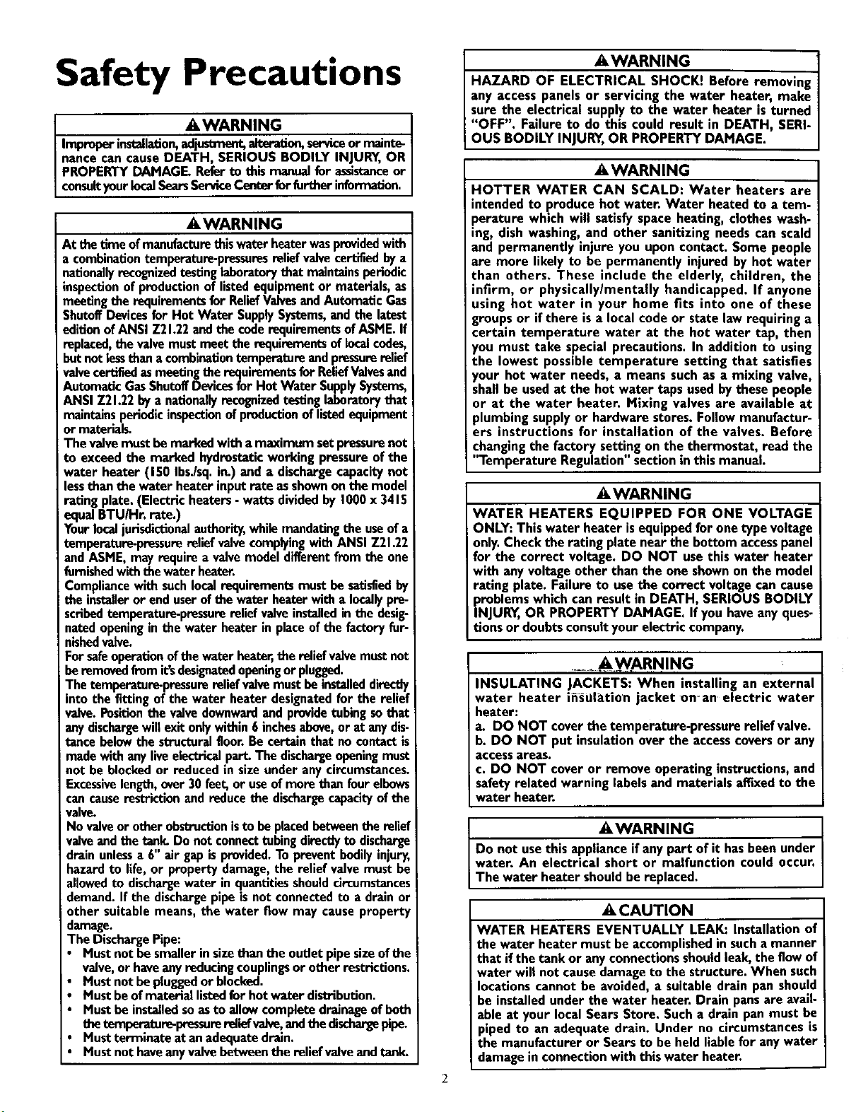
•,WARNING I
Improperinstallation,ad_ alteration,serviceor mainte-I
nance can causeDEATH, SERIOUS BODILY INJURY,OR
PROPERTYDAMAGE Referto thismanualfor assistanceor
consultyourlocalSearsServiceCont_ for further nformation.
A,WARNING
At thetime ofmanufacturethiswaterheaterwasprovidedwith
a combinationtemperature-pressuresrelief valvecertifiedbya
nationallyrecognizedtestinglaboratory that maintainsperiodic
inspectionof productionof listedequipmentor materials,as
meetingthe requirementsfor ReliefValvesandAutomaticGas
ShutoffDevicesfor Hot Water SupplySystems,and the latest
editionofANSI Z2h22 and the coderequirementsofASME.If
replaced,the valvemustmeet the requirementsof localcedes,
butnotlessthan a combinationtemperatureandpressurerelief
valvecertifiedasmeetingthe requirementsfor ReliefValvesand
AutomaticGasShutoffDevicesfor Hot Water SupplySystems,
ANSI Z21.22by a nationallyrecognizedtestinglaboratorythat
maintainsperiodic inspectionofproductionoflistedequipment
ormaterials.
The valvemustbemarked with a maximum setpressurenot
to exceedthe marked hydrostaticworkingpressureof the
water heater (150 Ibs./sq.in.) and a dischargecapacitynot
lessthan the water heater inputrate asshownonthe model
rating plate.(Electricheaters, watts dividedby 1000x 3415
equalBTUIHr. rate.)
Yourlocaljurisdictionalauthority,whilemandatingthe useof a
temperature-pressurereliefvalvecomplyingwith ANSI Z21.22
and ASME,mayrequire a valvemodeldifferentfrom the one
furnishedwiththewater heater.
Compliancewith suchlocalrequirementsmust be satisfiedby
the installeror enduserofthe water heaterwith a locallypre-
scribedtemperature-pressurereliefvalveinstalledin the desig-
natedopeningin the water heater in placeofthe factoryfor-
nishedvalve.
Forsafeoperationofthe waterheater,the reliefvalvemustnot
beremovedfromit'sdesigeai_lopeningor plugged.
Thetemperature-pressurereliefvalvemustbeinstalleddirectly
into the fitting of the water heater designatedfor the relief
valve.Fos_on the valvedownwardand providetubingsothat
anydischargewiltexitonlywithin 6 inchesabove,or at anydis-
tence belowthe structuralfloor.Becertain that nocontactis
madewith anyliveelectricalpart.The dischargeopeningmust
not be blockedor reducedin sizeunder anycircumstances.
Excessivelength,over30 feet,or useof more than fourelbows
cancauserestriction and reducethe dischargecapacityofthe
valve.
No valveor otherobstructionisto beplacedbetweenthe relief
valveand the tank.Do not connecttubingdirectlyto discharge
drain unlessa 6" air gap isprovided.To preventbodilyinjury,
hazardto llfe,or propertydamage,the relief valvemustbe
allowedto dischargewater in quantitiesshouldcircumstances
demand.If the dischargepipeisnot connectedto a drainor
other suitable means, the water flow may causeproperty
damage.
The DischargePipe:
• Mustnot be smallerinsizethan the outletpipesizeofthe
valve,or haveany reducingcouplingsor otherrestrictions.
Mustnot be pluggedor blocked.
Mustbeofmaterial listedfor hot water distribution.
Mustbe installedsoasto allow completedrainageofbeth
thetemperature-pressurereliefvadve,andthedischargepipe.
Mustterminate at anadequatedrain.
Mustnot haveanyvalvebetween the relief valveandtank.
AWARNING J
HAZARD OF ELECTRICAL SHOCK! Before removing
any access panels or servicing the water heater, make
sure the electrical supplyto the water heater is turned
"OFF". Failure to do this could result in DEATH, SERI-
OUS BOD LY NJURY,OR PROPERTY DAMAGE.
_,WARNING
HOTTER WATER CAN SCALD: Water heaters are
intended to producehot water. Water heated to a tem-
perature which will satisfyspaceheating, clothes wash-
ing, dish washing, and other sanitizing needs can scald
and permanently injure you upon contact. Some people
are more likely to be permanently injured by hot water
than others. These include the elderly, children, the
infirm, or physically/mentally handicapped. If anyone
using hot water in your home fits into one of these
groupsor ifthere is a localcode or state law requiring a
certain temperature water at the hot water tap, then
you must take special precautions. In addition to using
the lowest possible temperature setting that satisfies
your hot water needs, a means suchas a mixing valve,
shallbe usedat the hot water tapsusedby these people
or at the water heater. Mixing valves are available at
plumbingsupplyor hardware stores.Follow manufactur-
ers instructions for installation of the valves. Before
changingthe factory sett!ng on the thermostat, read the
Temperature Regulation sectionin this manual.
AWARNING
WATER HEATERS EQUIPPED FOR ONE VOLTAGE
ONLY: Thiswater heater isequippedfor one type voltage
only.Check the rating plate near the bottom accesspanel
for the correct voltage. DO NOT usethis water heater
with any voltageother than the one shownon the model
rating plate. Failure to usethe correct voltagecancause
problemswhich canresult in DEATH, SERIOUS BODILY
INJURY,OR PROPERTY DAMAGE. If you haveanyques-
tionsor doubtsconsultyourelectric company.
..... AWARN, ING
INSULATING JACKETS: When installing an external
water heater i_Ul_tion jacket on'an electric water
heater:
a. DO NOT cover the temperature-pressure relief valve.
b. DO NOT put insulationover the accesscoversor any
accessareas.
c. DO NOT cover or remove operating instructions,and
safetyrelated warning labelsand materials affixedto the
water heater.
_,WARNING
Do not usethis appliance if anypart of it hasbeen under
water. An electrical short or malfunction could occur.
The water heater shouldbe replaced.
A CAUTION
WATER HEATERS EVENTUALLY LEAK: Installation of
the water heater must be accomplishedin sucha manner
that ifthe tank or anyconnectionsshouldleak,the flow of
water will not causedamageto the structure.When such
locationscannot be avoided,a suitabledrain pan should
be installedunder the water heater. Drain pansare avail-
able at your localSearsStore. Sucha drain pan must be
piped to an adequate drain. Under no circumstancesis
the manufacturer or Searsto be heldliable for anywater
damage in connectionwith thiswater heater.
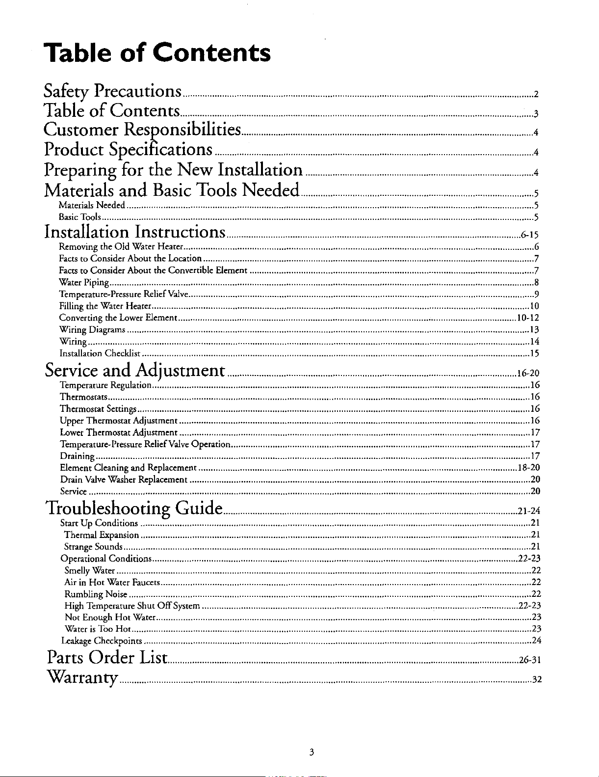
Table of Contents
cc_.__oa_wPrecautions ...............................................................................................................................................2
Table of Contents ................................................................................................................................................3
Customer Responsibilities .......................................................................................................................4
Product Specifications ..................................................................................................................................4
Preparing for the New Installation .............................................................................................4
Materials and Basic Tools Needed ...............................................................................................5
Materials Needed ...................................................................................................................................................................... 5
Basic Tools ................................................................................................................................................................................ 5
Installation Instructions ........................................................................................................................6-15
Removing the Old Water Heater ............................................................................................................................................... 6
Facts to Consider About the Location ....................................................................................................................................... 7
Facts to Consider About the Convertible Element .................................................................................................................... 7
Water Piping ............................................................................................................................................................................. 8
Temperature-Pressure Rdief Valve ............................................................................................................................................. 9
Filling the Water Heater .......................................................................................................................................................... 10
Converting the Lower Element .......................................................................................................................................... 10-12
Wiring Diagrams .................................................................................................................................................................... 13
Wiring .................................................................................................................................................................................... 14
Installation Checklist .............................................................................................................................................................. 15
Service and Adjustment ......................................................................................................................16-20
Temperature Regulation .......................................................................................................................................................... 16
Thermostats ............................................................................................................................................................................ 16
Thermostat Settings ................................................................................................................................................................ 16
Upper Thermostat Adjustment ............................................................................................................................................... 16
Lower Thermostat Adjustment ............................................................................................................................................... 17
Temperature-Pressure Relief Valve Operation .......................................................................................................................... 17
Draining ................................................................................................................................................................................. 17
Element Cleaning and Replacement .................................................................................................................................. 18-20
Drain Valve Washer Replacement ........................................................................................................................................... 20
Service .................................................................................................................................................................................... 20
Troubleshooting Guide ........................................................................................................................21-24
Start Up Conditions ............................................................................................................................................................... 21
Thermal Expansion ............................................................................................................................................................... 21
Strange Sounds ...................................................................................................................................................................... 21
Operational Conditions ..................................................................................................................................................... 22-23
Smelly Water ......................................................................................................................................................................... 22
Air in Hot Water Faucets ....................................................................................................................................................... 22
Rumbling Noise .................................................................................................................................................................... 22
High Temperature Shut OffSystem ................................................................................................................................. 22-23
Not Enough Hot Water ......................................................................................................................................................... 23
Water is Too Hot ................................................................................................................................................................... 23
Leakage Checkpoints .............................................................................................................................................................. 24
Parts Order List ...............................................................................................................................................26-31
Warranty ........................................................................................................................................................................32
3
Customer Responsibilities
Thank You for purchasing a Sears water heater.
Properly installed and maintained, it should give you years of
trouble free service. If you should decide that you want the new
water heater professionally installed, contact the local Sears
Service Center or any Sears store. They will arrange for prompt,
quality installation by Sears authorized contractors.
Abbreviations Found In This Instruction Manual
U.L.-Underwriters Laboratories, 333 Pfingsten Rd.,
Northbrook, IL 60062
National Electrical Code-This publication is available from your
local government or public library or electric company or by
writing to U.L. above.
A.N.S.I.-American National Standards Institute
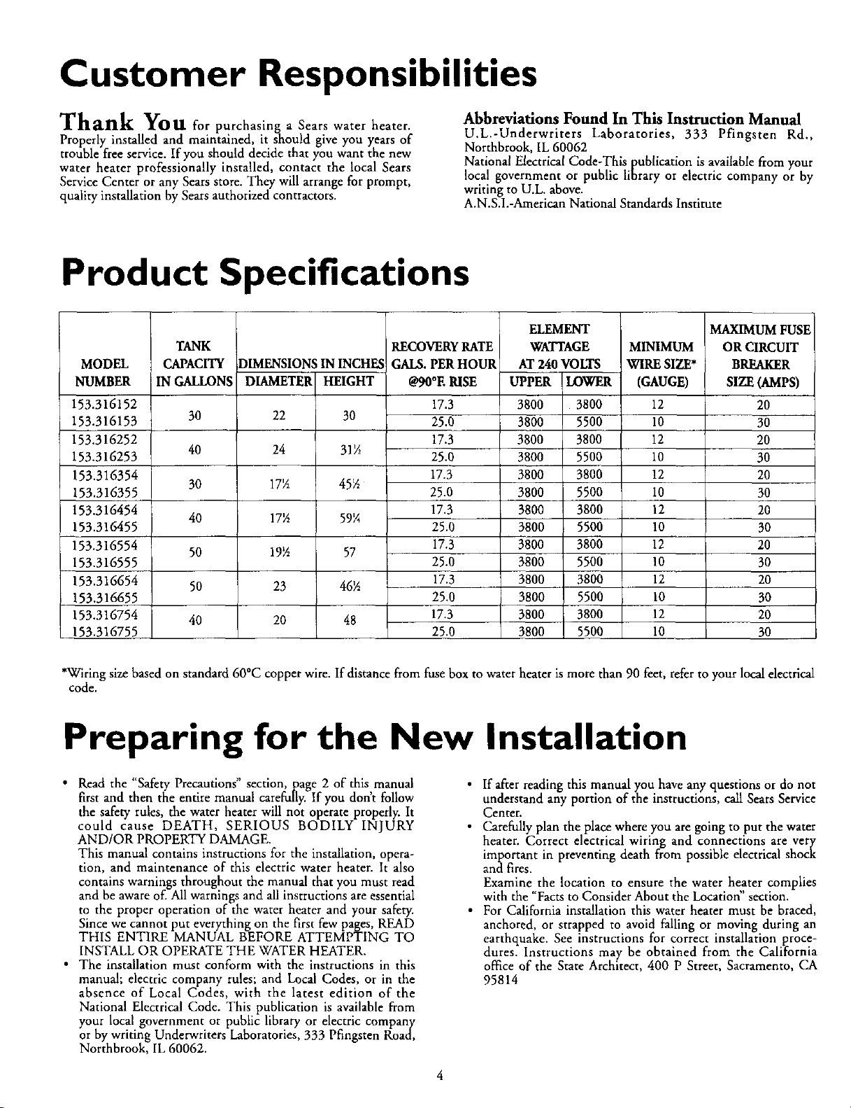
Product Specifications
MODEL
NUMBER
153.316152
153.316153
153.316252
153.316253
153.316354
153.316355
153.316454
153.316455
153.316554
153.316555
153.316654
153.316655
153.316754
153.316755
TANK
CAPACITY
IN GAH_NS
30
40
3O
40
50
50
4O
DIMENSIONS ININCHFA
DIAMETER HEIGHT
22 30
24 31_
17_ 45½
17_ 59¼
19½ 57
23 46_
20 48
RECOVERYRATE
GALS.PERHOUR
@90°ERISE
17.3
25.0
17.3
25.0
17.3
25.0
17.3
25.O
17.3
25.0
17.3
25.0
17.3
25.0
ELEMENT
WATTAGE
AT 24OVOLTS
UPPER LOWER
3800 3800
3800 5500
380O 3800
3800 5500
3800 3800
3800 5500
3800 3800
3800 5500
3800 3800
3800 5500
3800 3800
3800 5500
3800 3800
3800 5500
MINIMUM
WIRE SIZE*
(GAUGE)
12
10
12
10
12
10
12
10
12
10
12
10
12
10
MAXIMUM FUSE
OR CIRCUIT
BREAKER
SIZE(AMPS)
20
3O
2O
30
20
30
20
30
20
3O
20
3O
2O
30
*Wiring size based on standard 60°C copper wire. If distance from fuse box to water heater is more than 90 feet, refer to your local electrical
code.
Preparing for the New Installation
• Read the "Safety Precautions" section, page 2 of this manual
first and then the entire manual carefully. If you don't follow
the safety rules, the water heater will not operate properly. It
could cause DEATH, SERIOUS BODILY INJURY
AND/OR PROPERTY DAMAGE.
This manual contains instructions for the installation, opera-
tion, and maintenance of this electric water heater. It also
contains warnings throughout the manual that you must read
and be aware of. All warnings and all instructions are essential
to the proper operation of the water heater and your safety.
Since we cannot put everything on the first few pages, READ
THIS ENTIRE MANUAL BEFORE ATTEMPTING TO
INSTALL OR OPERATE THE WATER HEATER.
• The installation must conform with the instructions in this
manual; electric company rules; and Local Codes, or in the
absence of Local Codes, with the latest edition of the
National Electrical Code. This publication is available from
your local government or public library or electric company
or by writing Underwriters Laboratories, 333 Pfingsten Road,
Northbrook, IL 60062.
• If after reading this manual you have any questions or do not
understand any portion of the instructions, call Sears Service
Center.
• Carefully plan the place where you are going to put the water
heater. Correct electrical wiring and connections are very
important in preventing death from possible electrical shock
and fires.
Examine the location to ensure the water heater complies
with the "Facts to Consider About the Location" section.
• For California installation this water heater must be braced,
anchored, or strapped to avoid falling or moving during an
earthquake. See instructions for correct installation proce-
dures. Instructions may be obtained from the California
office of the State Architect, 400 P Street, Sacramento, CA
95814
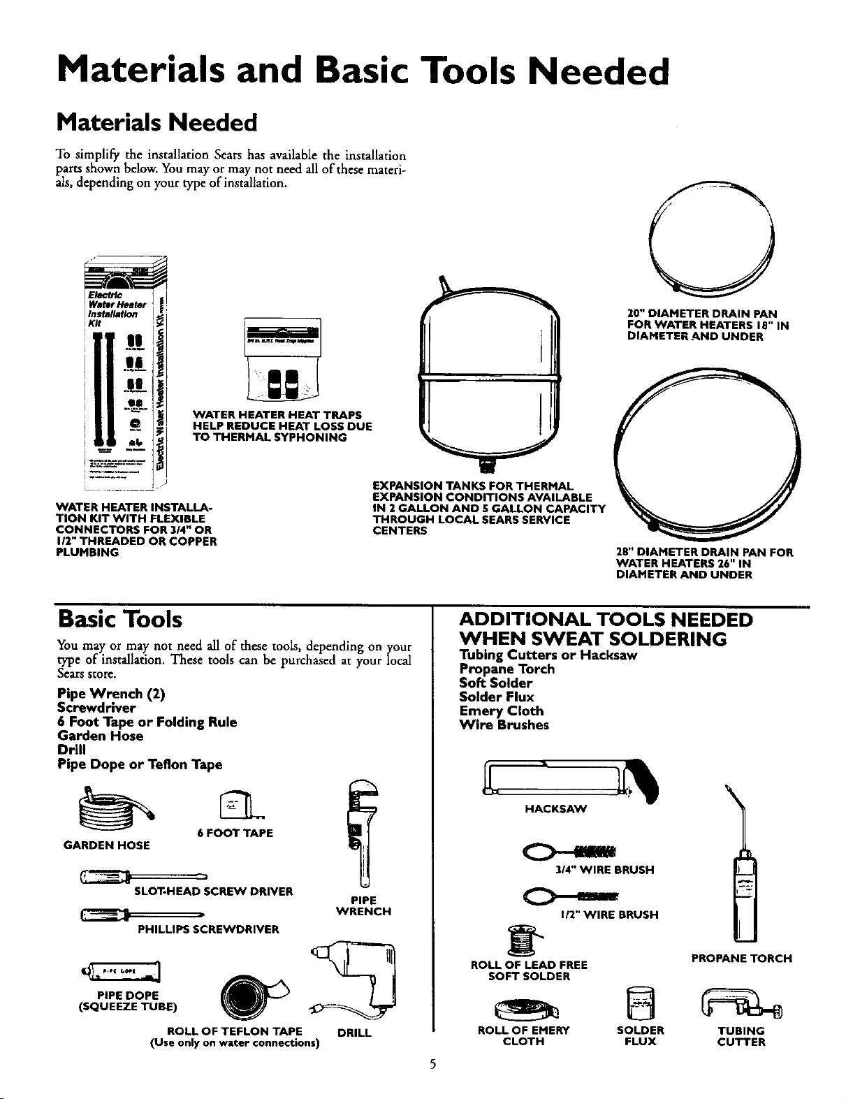
Materials and Basic Tools Needed
Materials Needed
To simplify the installation Sears has available the installation
parts shown below. You may or may not need all of these materi-
als, depending on your type of installation.
i IB
...... WATER HEATER HEAT TRAPS
CENTERS
HELP REDUCE HEAT LOSS DUE
TO THERMAL SYPHONING
....... EXPANSION TANKS FOR THERMAL
EXPANSION CONDITIONS AVAILABLE
WATER HEATER INSTALLA- IN 2 GALLON AND SGALLON CAPACITY
TION KIT WITH FLEXIBLE THROUGH LOCAL SEARS SERVICE
CONNECTORS FOR 3/4" OR
I/2" THREADED OR COPPER
PLUMBING
20" DIAMETER DRAIN PAN
FOR WATER HEATERS 18" IN
DIAMETER AND UNDER
28" DIAMETER DRAIN PAN FOR
WATER HEATERS 26" IN
DIAMETER AND UNDER
Basic Tools
You may or may not need all of these tools, depending on ytour
type of installation. These tools can be purchased at your local
Searsstore.
Pipe Wrench (2)
Screwdriver
6 Foot Tape or Folding Rule
Garden Hose
Drill
Pipe Dope or Teflon Tape
6 FOOT TAPE
GARDEN HOSE
SLOT-HEAD SCREW DRIVER
PHILLIPS SCREWDRIVER
PIPE
WRENCH
PIPE DOPE
(SQUEEZE TUBE)
ROLL OF TEFLON TAPE DRILL
(Use only on water connections)
ADDITIONAL TOOLS NEEDED
WHEN SWEAT SOLDERING
Tubing Cutters or Hacksaw
Propane Torch
Soft Solder
Solder Flux
Emery Cloth
Wire Brushes
5
HACKSAW
314" WIRE BRUSH
112"WIRE BRUSH
\
_'_ PROPANE TORCH
ROLL OF LEAD FREE
SOFT SOLDER
ROLL OF EMERY SOLDER TUBING
CLOTH FLUX CUTTER
Installation Instructions
Removing the Old Water
Heater
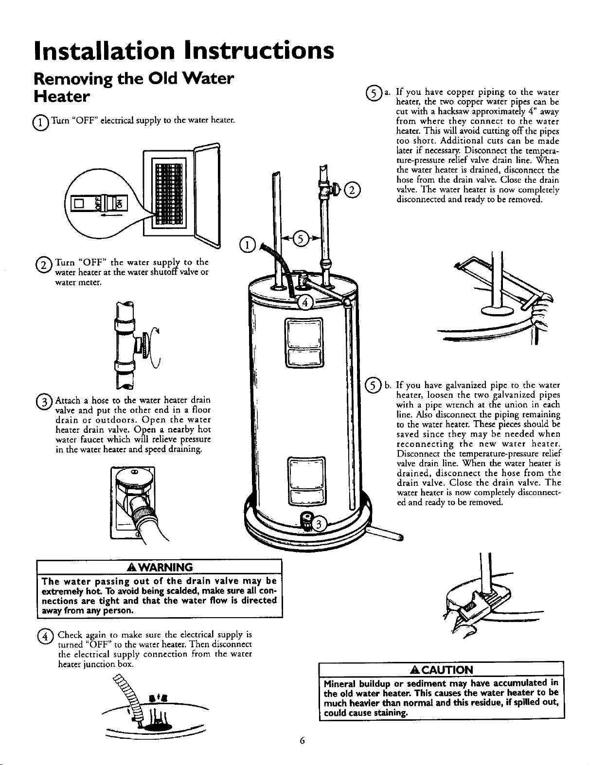
G Turn "OFF" electrical supply to the water heater.
Q Turn "OFF" the water supply to the
water heater at the water shutoffvalve or
water meter.
Q Attach a hose to the water heater drain
valve and put the other end in a floor
drain or outdoors. Open the water
heater drain valve. Open a nearby hot
water faucet which will relieve pressure
in the water heater and speed draining.
_,WARNING
The water passing out of the drain valve may be
extremely hot. Toavoidbeing scalded,make sure all con-
I nections are tight and that the water flow is directed
[ awayfrom any person.
Q Check make the electrical supply isagain _O
sure
turned OFF to the water heater. Then disconnect
the electrical supply connection from the water
heater junction box.
Qa. If have piping to the water
you copper
heater, the two copper water pipes can be
cut with a hacksaw approximately 4" away
from where they connect to the water
heater. This will avoid cutting off the pipes
too short. Additional cuts can be made
later if necessary. Disconnect the tempera-
ture-pressure relief valve drain line. When
the water heater is drained, disconnect the
hose from the drain valve. Close the drain
valve. The water heater is now completely
disconnected and ready to be removed.
Q b. you galvanized pipe to water
If have the
heater, loosen the two galvanized pipes
with a pipe wrench at the union in each
line. Also disconnect the piping remaining
to the water heater. These pieces should be
saved since they may be needed when
reconnecting the new water heater.
Disconnect the temperature-pressure relief
valve drain line. When the water heater is
I drained, disconnect the hose from the
[ drain valve. Close the drain valve. The
• water heater is now completely disconnect-
dand ready to be removed.
A CAUTION I
Mineral buildup or sediment may have accumulated in I
the old water heater. This causesthe water heater to be I
much heavierthan normal and this residue,if spilledout,
[ couldcausestaining. I
Installation Instructions (cont'd)
Facts to Consider About the
Location
Facts to Consider About the
Convertible Lower Element
You should carefully choose an indoor location for the new water
heater, because the placement is a very important consideration
for the safety of the occupants in the building and for the most
economical use of the appliance. This water heater is not intend-
ed for outdoor installation.
Whether replacing an old water heater or putting the water
heater in a new location, the following critical points must be
observed.
• The location selected should be indoors as close to and as cen-
tralized with the water piping system as possible. This water
heater, as well as all water heaters, will eventually leak. Do not
install without adequate drainage provisions where water flow
will cause damage.
_CAUTION
WATER HEATERS EVENTUALLY LEAK: Installation of
the water heater must be accomplishedin sucha man-
ner that if the tank or any connectionsshouldleak, the
flow of water will not cause damage to the structure.
When suchlocationscannot be avoided,a suitable drain
pan should be installed under the water heater. Drain
pansare availableat your local Searsstores.Such a drain
pan must be piped to an adequate drain. Under no cir-
cumstances is the manufacturer or Sears to be held
liablefor anywater damage in connectionwith thiswater
heater.
The Upper Element (if a double element model), is a conven-
tional 3800 watt element which only operates at its rated
wattage on 240 volts. (See rating plate on water heater).
The Lower Element of the water heater can be converted from
operation at 3800 watts to 5500 watts on a 240 volt system.
Read and follow water heater warnings and instructions.If after
reading these instructions in this manual, if you do not under-
stand any portion, call Sears Service Center.
A,WARNING
Before making the conversionto 5500 watts, check the
(I) power supply...must be 240 volts, (2) wiring...10
gauge AWG, Type TW, 60°C or equivalent, and (3)
Circuit breakers or fusing...capable of 30 amp loading.
Also, the installation must conform with this manual,
local codes and electric utility rules. Failure to comply
can result in DEATH, SERIOUS BODILY INJURY, OR
PROPERTY DAMAGE.
&CAUTION
INSTALLATION IN RESIDENTIAL GARAGES: The
water beater must be located and/or protected so it is
not subjectto physca damageby a mov ngvehc e.
• The location selection must provide adequate clearances for
servicing and proper operation of the water heater.
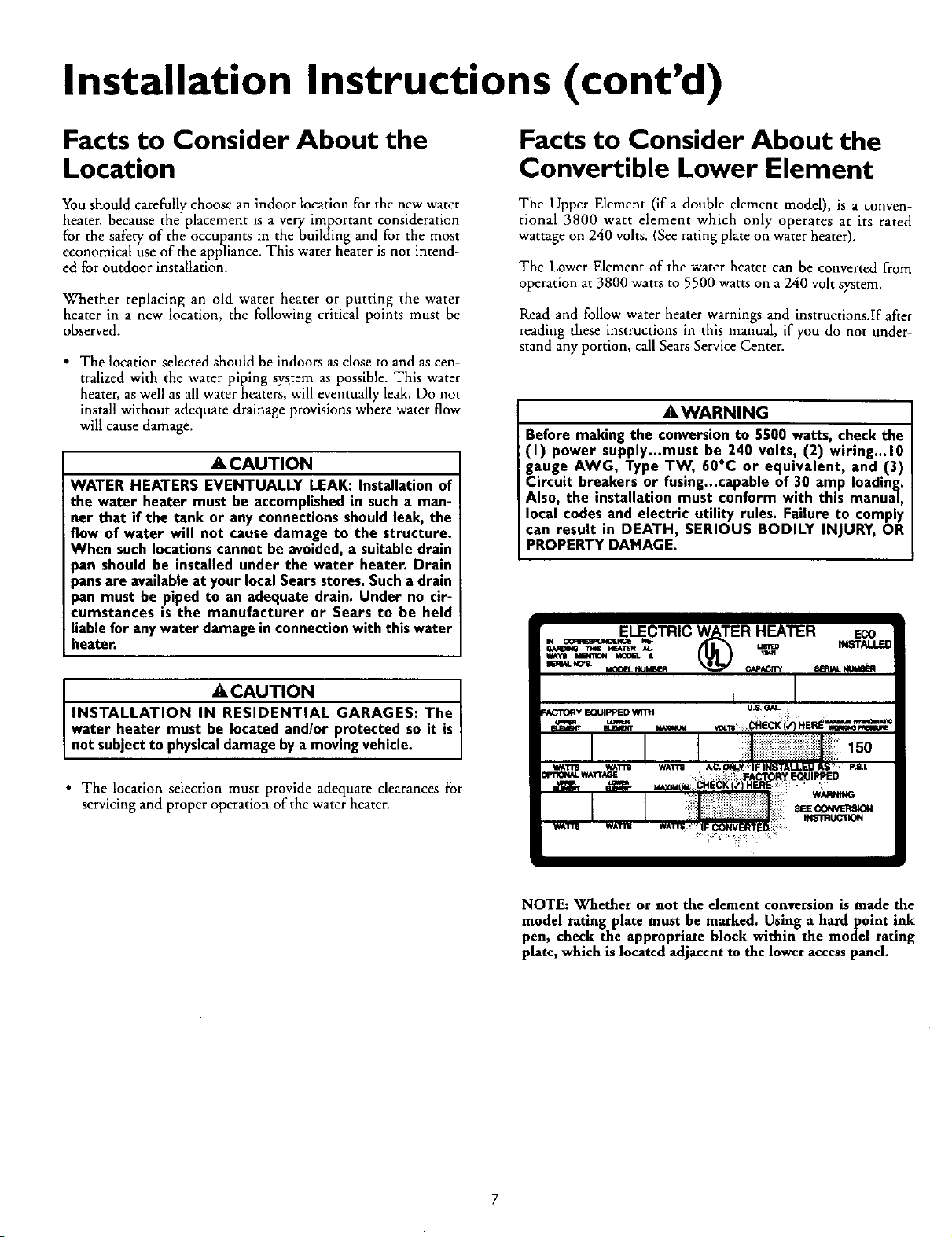
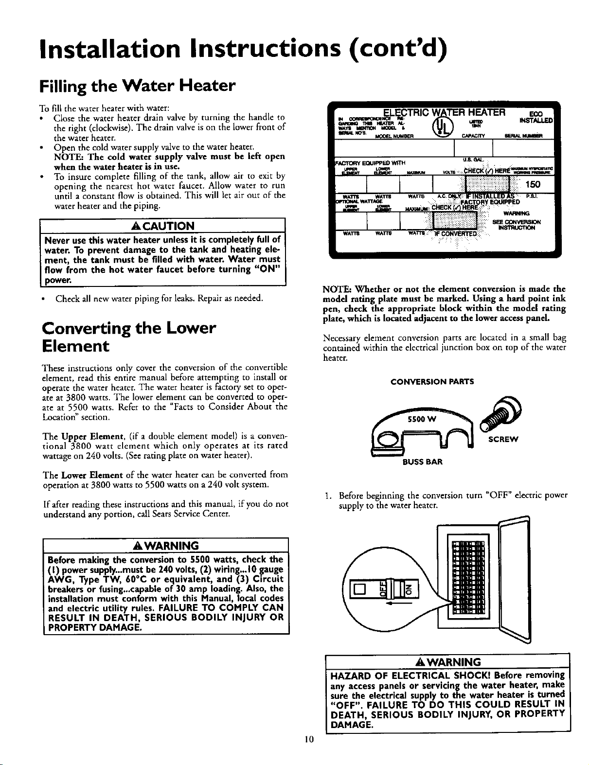
NOTE: Whether or not the element conversion is made the
model rating plate must be marked. Using a hardpoint ink
pen, check the appropriate block within the model rating
plate, which is located adjacent to the lower access panel.
Installation Instructions (cont'd)
Water Piping
_,WARNING
HOTTER WATER CAN SCALD: Water heaters are
intended to produce hot water. Water heated to a tem-
)erature which will satisfyspaceheating, clothes wash-
ing, dish washing, and other sanitizing needs can scald
and permanently injure you upon contact. Some people
are more likely to be permanently injured by hot water
than others. These include the elderly, children, the
infirm, or physically/mentally handicapped. If anyone
using hot water in your home fits into one of these
groupsor if there isa local code or state law requiring a
certain temperature water at the hot water tap, then
you must take special precautions. In addition to using
the lowest possible temperature setting that satisfies
your hot water needs, a means suchas a mixing valve,
shallbe usedat the hot water taps used bythese people
or at the water heater. Mixing valves are available at
)lumbing supplyor hardware stores.Follow manufactur-
ers instructions for installation of the valves. Before
changingthe factory settingon the thermostat, read the
"Temperature Regulation"sectionin this manual.
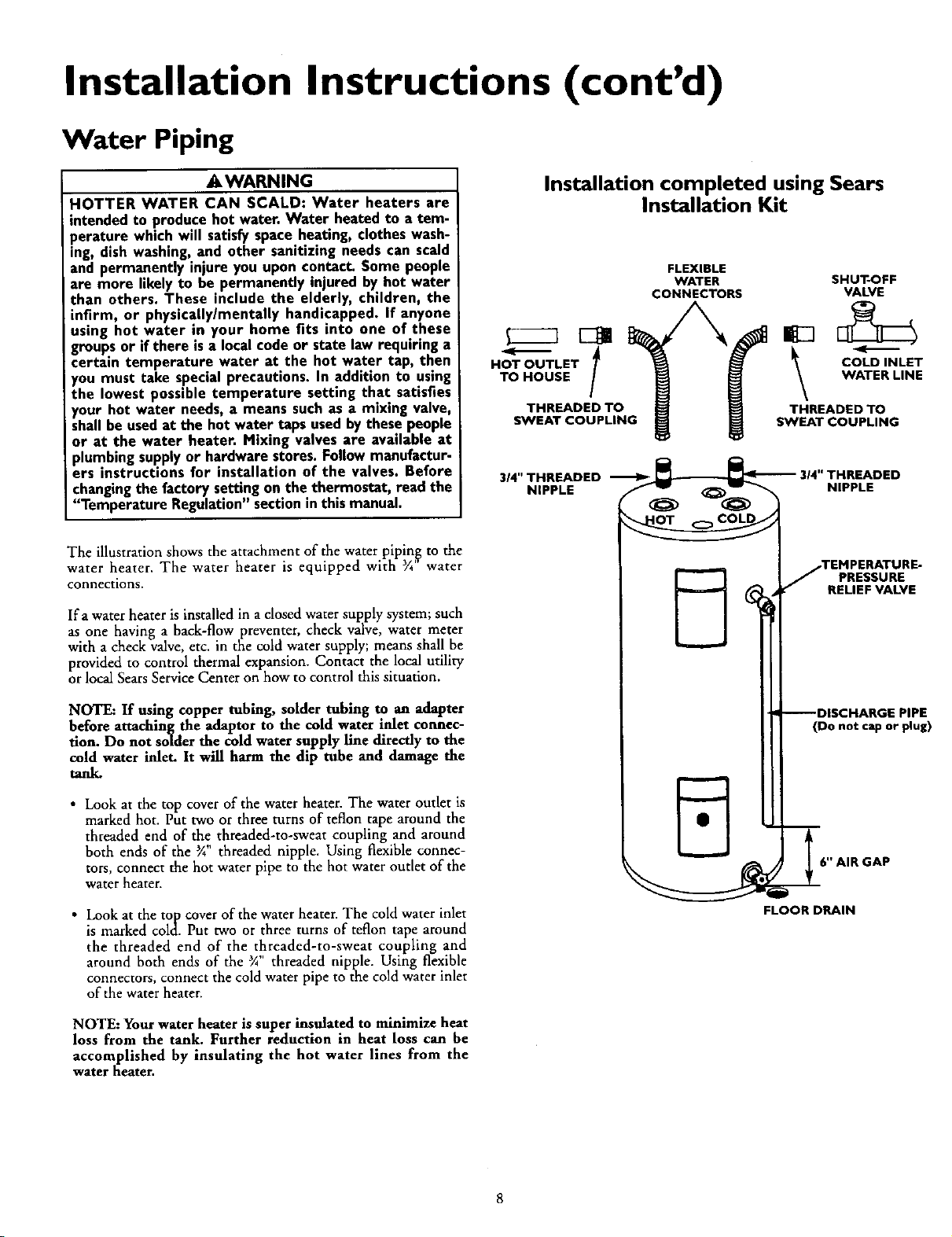
The illustration shows the attachment of the water piping to the
water heater. The water heater is equipped with ¼" water
connections.
Ira water heater is installed in a closed water supply system; such
as one having a back-flow preventer, check valve, water meter
with a check valve, etc. in the cold water supply; means shall be
provided to control thermal expansion. Contact the local utility
or local Sears Service Center on how to control this situation.
NOTE: If using copper tubing, solder tubing to an adapter
before attaching the adaptor to the cold water inlet connec-
tion. Do not solder the cold water supply line directly to the
cold water inlet. It will harm the dip tube and damage the
tank.
• Look at the top cover of the water heater. The water outlet is
marked hot. Put two or three turns of teflon tape around the
threaded end of the threaded-to-sweat coupling and around
both ends of the 3A threaded nipple. Using flexible connec-
tors, connect the hot water pipe to the hot water outlet of the
water heater.
• Look at the top cover of the water heater. The cold water inlet
is marked cold. Put two or three turns of teflon tape around
the threaded end of the threaded-to-sweat coupling and
around both ends of the ¾ threaded nipple. Using flexible
connectors, connect the cold water pipe to the cold water inlet
of the water heater.
Installation completed using Sears
Installation Kit
HOT OUTLET
TO HOUSE
THREADED TO
SWEAT COUPLING
FLEXIBLE
WATER
CONNECTORS
SHUT-OFF
VALVE
\---
COLDINLET
WATER LINE
THREADED TO
SWEAT COUPLING
3,4" THREADEDNIPPLE_ 314" THp_ELADED
_.TEMPERATURE-
PRESSURE
RELIEF VALVE
--DISCHARGE PIPE
(Do not cap or plug)
6" AIR GAP
FLOOR DRAIN
NOTE: Your water heater is super insulated to minimize heat
loss from the tank. Further reduction in heat loss can be
accomplished by insulating the hot water lines from the
water heater.
Installation Instructions (cont'd)
Temperature-Pressure
Relief Valve
_,WARNING
At the time of manufacture this water heater was provid-
ed with a combination temperature-pressuresrelief valve
certified bya nationally recognized testinglaboratory that
maintains periodic inspection of production of listed
equipment or materials, as meeting the requirements for
ReliefValvesand Automatic Gas ShutoffDevicesfor Hot
Water Supply Systems, and the latest edition of ANSI
Z21.22 and the code requirements of ASHE. If replaced,
the valvemust meet the requirements of local codes,but
not lessthan a combination temperature and pressure
relief valve certified as meeting the requirements for
ReliefValvesand Automatic Gas ShutoffDevicesfor Hot
Water SupplySystems,ANSI Z21.22 bya nationallyrecog-
nizedtestinglaboratory that maintainsperiodicinspection
ofproductionoflistedequipmentor materials.
The valve must be marked with a maximum set pressure
not to exceedthe marked hydrostaticworkingpressureof
the water heater (150 Ibs./sq.in.) and a dischargecapacity
not lessthan the water heater input rate asshownon the
model rating plate. (Electric heaters - watts divided by
1000x 3415 equalBTU/Hr. rate.)
Yourlocaljurisdictionalauthority,while mandatingthe use
of a temperature-pressure relief valve complying with
ANSI Z21.22 and ASME, may require a valvemodel differ-
ent from the onefurnishedwith the water heater.
Compliance with such local requirements must be satis-
fied bythe installeror end userof the water heater with a
locally prescribed temperature-pressure relief valve
installedin the designatedopeningin the water heater in
daceofthe factory furnishedvalve.
For safe operation of the water heater, the relief valve
must not be removed from it's designated opening or
plugged.
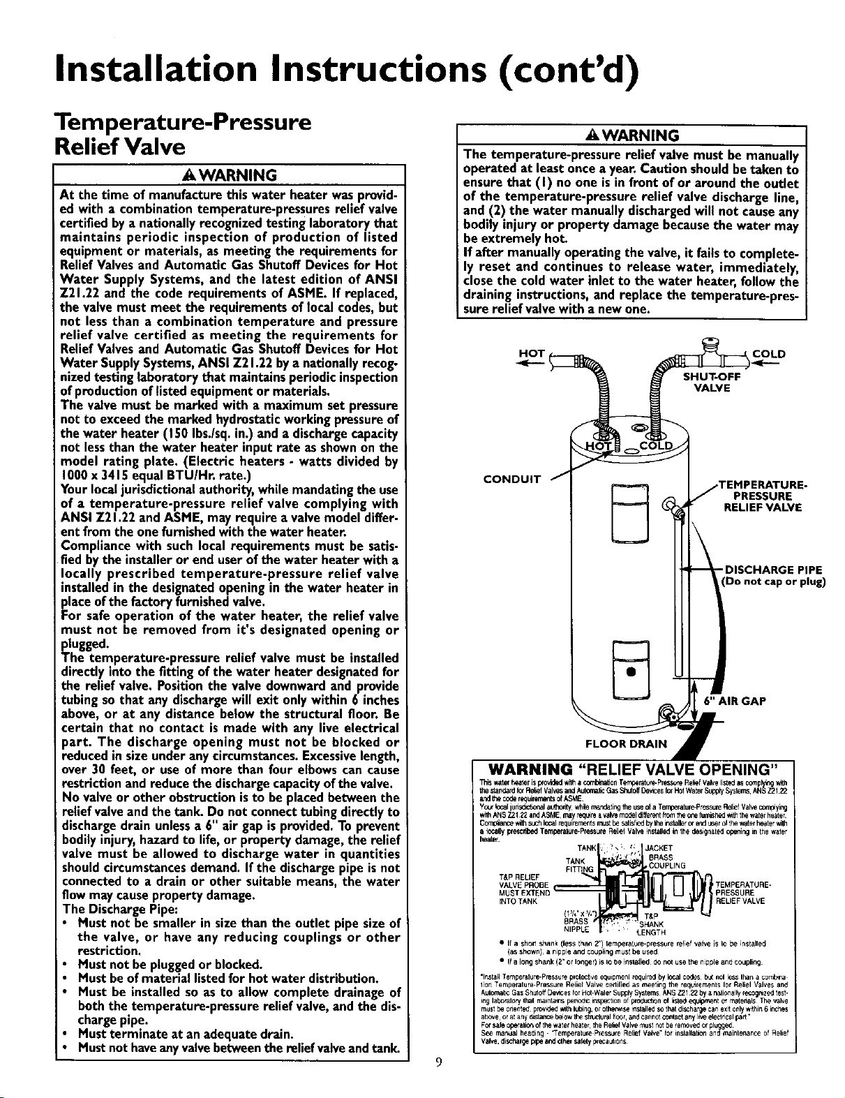
The temperature-pressure relief valve must be installed
directly into the fitting of the water heater designatedfor
the relief valve. Positionthe valve downwardand provide
tubing sothat anydischargewill exit onlywithin 6 inches
above, or at any distance below the structural floor. Be
certain that no contact is made with any live electrical
)art. The discharge opening must not be blocked or
reduced in sizeunder anycircumstances.Excessivelength,
over 30 feet, or use of more than four elbowscan cause
restriction and reduce the dischargecapacityofthe valve.
No valveor other obstructionisto be placedbetween the
relief valveandthe tank. Do not connecttubingdirectly to
dischargedrain unlessa 6" air gap isprovided.To prevent
bodilyinjury,hazard to life, or property damage,the relief
valve must be allowed to discharge water in quantities
shouldcircumstancesdemand. If the dischargepipeisnot
connectedto a drain or other suitable means, the water
flow may causepropertydamage.
The DischargePipe:
• Must not be smaller in sizethan the outlet pipe sizeof
the valve, or have any reducing couplings or other
restriction.
Must not bepluggedor blocked.
Mustbe ofmaterial listedfor hot water distribution.
Must be installedso as to allow complete drainage of
boththe temperature-pressurerelief valve,and the dis-
chargepipe.
Mustterminate at anadequatedrain.
Mustnothaveanyvalvebetweenthe relief valveandtank.
• ,WARNING
The temperature-pressure relief valve must be manually
operated at leastonce a year.Caution shouldbe taken to
ensurethat (I) no one is in front of or around the outlet
of the temperature-pressure relief valve dischargeline,
and (2) the water manually dischargedwill not causeany
bodily injury or property damagebecausethe water may
beextremely hot.
If after manually operating the valve, it fails to complete-
ly reset and continues to release water, immediately,
close the cold water inlet to the water heater, follow the
draining instructions,and replace the temperature-pres-
surerelief valvewith a new one.
H_OT ( COLD
SHUT-OFF
VALVE
CONDUIT J
FLOOR DRAIN •
TEMPERATURE-
J PRESSURE
RELIEF VALVE
DISCHARGE PIPE
Do not cap or plug)
6" AIR GAP
r
WARNING "RELIEF VALVE OPENING"
Thiswaterheaterisp_ovidedwilha co,_on Tempe_ Press_eRe_efValvelistedasco_plyingw_h
thestandardfo_RediQfValwsandAulomalicGasShutoffDewcesforH01WaterSupp_Systems,ANSZ2122
andthecoderequirementsofASME
Yc_'lc_ judsd_tl,0nalau_hontywhle rn_ndatingtheuseofa Tempetatule-Pr_suleRelLefValve_¥rg
withANS72122andASME,may_Ie a vah.emodeldlffelentPoretheonefurnished_ thewaterheater
Comp_ar_ewithsuchlocalrequirementsr_st be_ltisfbedbytheinslallerc_endt_el of thewaterheater_h
a legally prescribedTempelalure-PteSsLJreRe[_elValveinstalledin the designatedepe_ir,g inthe wafer
heate_
TANK : ' _ ; t, JACKET
, r_.,
TANK * 1" BRASS
FITTING COUPLING
VALVE PROBE TEMPERATURE-
MUST EX_rEND PRESSURE
iNTO TANK RELIEFVALVE
BRASS SHANK
• I1 a short shank (less lhan 2") temperature-pressure reqief valve is Io be installe_J
(as shown}, a nipple and coup_in 9 must be used
• If a long shank (2" of loiter) is IO be in sla_led d<Jriot us_ the nipple end coupling
"Ins{all Tempetalure.Pre_ure prolective equipmenl _uir_ by local codes but nol less If,an a combine
lion Temperature-P,sssui8 Relic I Valve cetli{ied as meeting the requirernenls lot Reliel Valves and
Aulomauc Gas Shuloff De_,-_es for Hot.Waler Supply Syslems ANS Z21 22 by a helically recognized test.
rig labO_alory that r_ant ains peno_c ft_spection of production o{ lisle_ equipment el rnatehals The valve
mUSl he onenled provKled _th lubin9, or olhen_se i_slaJlod SOthat discUarge can exit only _thin 6 inches
above¸ o, at any d_stancebelow Ibe 5tnJcforelflOOr,and cannot contact any live electlica_ part
For safe operalio_ of the water heatel, the Rehef Valve must not be iemoved or plugged¸
See maflua_ headirlg. "Temperah_re Pressure Relief Valve" {of il_slallatitl_ and mainlenance of Relief
Valve, discharg_ p_peand elher salety pr_autions
Installation Instructions (cont'd)
Filling the Water Heater
To fill the water heater with water:
Close the water heater drain valve by turning the handle to
the right (clockwise). The drain valve is on the lower front of
the water heater.
• Open the cold water supply valve to the water heater.
NOTE: The cold water supply valve must be left open
when the water heater is in use.
To insure complete filling of the tank, allow air to exit by
opening the nearest hot water faucet. Allow water to run
until a constant flow is obtained. This will let air out of the
water heater and the piping.
•,CAUTION [
Never usethis water heater unlessit iscompletely full of
water. To prevent damage to the tank and heating ele-
ment the tank must be filled with water. Water must
flow from the hot water faucet before turning "ON"
power.
Check all new water piping for leaks. Repair as needed.
Converting the Lower
Element
These instructions only cover the conversion of the convertible
element, read this entire manual before attempting to install or
operate the water heater. The water heater is factory set to oper-
ate at 3800 watts. The lower element can be converted to oper-
ate at 5500 watts. Refer to the "Facts to Consider About the
Location" section.
The Upper Element, (if a double element model) is a conven-
tional 3800 watt element which only operates at its rated
wattage on 240 volts. (See rating plate on water heater).
The Lower Element of the water heater can be converted from
operation at 3800 watts to 5500 watts on a 240 volt system.
If after reading these instructions and this manual, if you do not
understand any portion, call Sears Service Center.
NOTE: Whether or not the element conversion is made the
model rating plate must be marked. Using a hard point ink
pen, check the appropriate block within the model rating
plate, which is located adjacent to the lower access p_Lnel.
Necessary element conversion parts are located in a small bag
contained within the electrical junction box on top of the water
heater.
CONVERSION PARTS
BUSS BAR
1. Before beginning the conversion turn "OFF" electric power
supply to the water heater.
_,WARNING
Before making the conversionto 5500 watts, check the
(I) power supply-must be 240 volts,(2) wiring...10 gauge
AWG, Type TW, 60ec or equivalent, and (3) Circuit
breakers or fusing...capableof 30 amp loading.Also, the
installation must conform with this Manual, local codes
and electric utility rules. FAILURE TO COMPLY CAN
RESULT IN DEATH, SERIOUS BODILY INJURY OR
PROPERTY DAMAGE.
10
AWARNING
HAZARD OF ELECTRICAL SHOCKI Before removing
any access panels or servicing the water heater, make
sure the electrical supply to the water heater is turned
"OFF", FAILURE TO DO THIS COULD RESULT IN
DEATH, SERIOUS BODILY INJURY, OR PROPERTY
DAMAGE.
Installation Instructions (cont'd)
Converting the Lower
Element (cont'd)
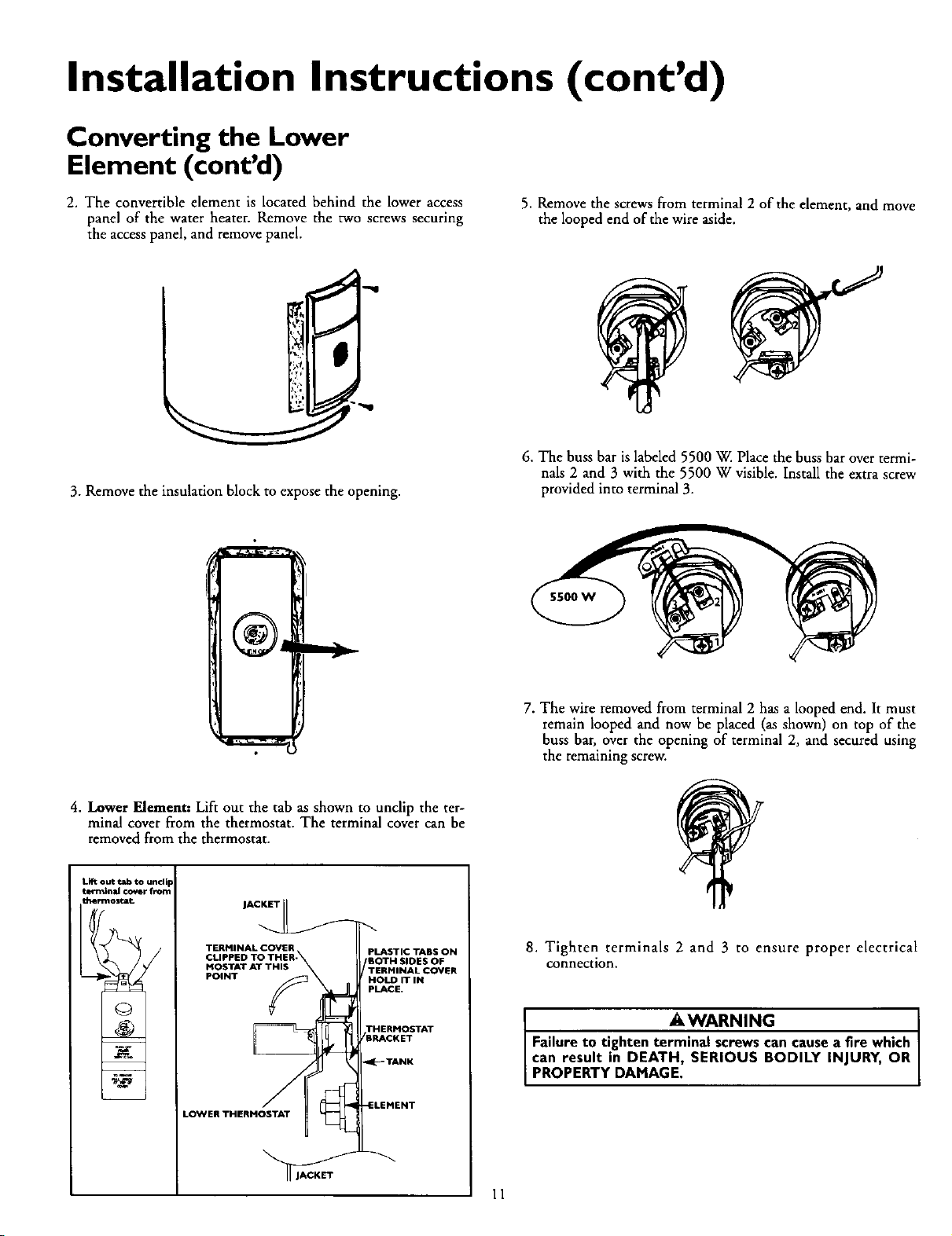
2. The convertible element is located behind the lower access
panel of the water heater. Remove the two screws securing
the access panel, and remove panel.
5. Remove the screws from terminal 2 of the element, and move
the looped end of the wire aside.
3. Remove the insulation block to expose the opening.
6. The buss bar is labeled 5500 W. Place the buss bar over termi-
nals 2 and 3 with the 5500 W visible. Install the extra screw
provided into terminal 3.
7. The wire removed from terminal 2 has a looped end. It must
remain looped and now be placed (as shown) on top of the
buss bar, over the opening of terminal 2, and secured using
the remaining screw.
4. Lower Element: Lift out the tab as shown to unclip the ter-
minal cover from the thermostat. The terminal cover can be
removed from the thermostat.
Lift out tab to unclip
terminaJ cover from
thermostat
TERMINAL COVER
CLIPPED TO THER-
MOSTAT AT THIS
POINT _
.-._1
LO_VERTHERMOSTAT --_
PLASTIC TABS ON
mOTH SIDES OF
TERMINAL COVER
HOLD IT IN
PLACE.
THERMOSTAT
BRACKET
_:_- TANK
-ELEMENT
8. Tighten terminals 2 and 3 to ensure proper electrical
connection.
AWARNING
Failure to tighten terminal screws can cause a Ere which
can result in DEATH, SERIOUS BODILY INJURY, OR
I PROPERTY DAMAGE,
11
Installation Instructions (cont'd)
Converting the Lower
Element (cont'd)
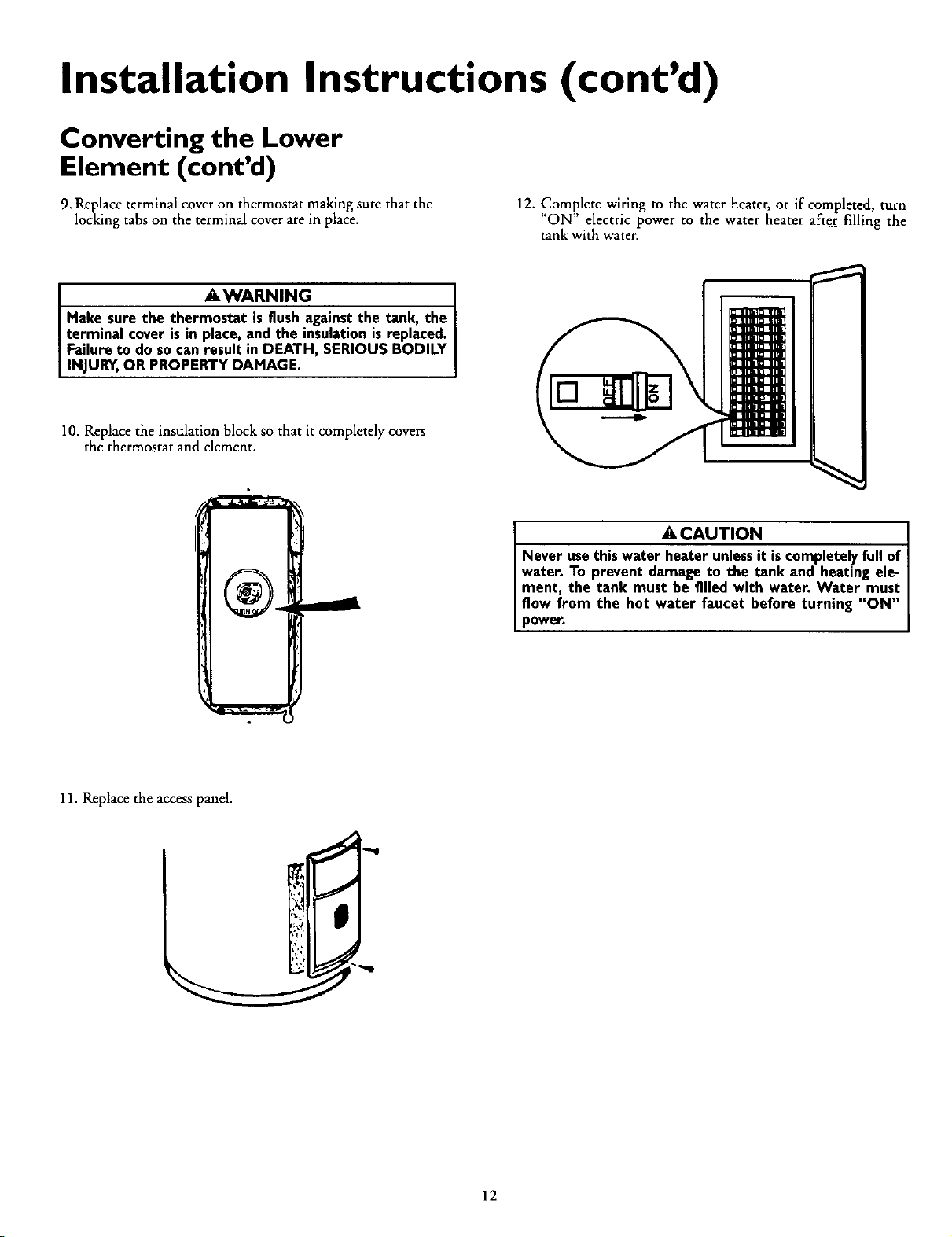
9. Replace terminal cover on thermostat making sure that the
locking tabs on the terminal cover are in place.
12. Complete wiring to the water heater, or if completed, turn
"ON" electric power to the water heater after filling the
tank with water.
_E,WARNING
Make sure the thermostat is flush againstthe tank, the
terminal cover isin place, and the insulation_sreplaced.
Failure to do socan result in DEATH, SERIOUS BODILY
NJURY,OR PROPERTY DAMAGE.
10. Replace the insulation block so that it completely covers
the thermostat and element.
_, CAUTION
Never usethis water heater unlessit iscompletely full of
water. To prevent damage to the tank and heating ele-
ment, the tank must be filled with water. Water must
flow from the hot water faucet before turning "ON"
power.
11. Replace the access panel.
12
Installation Instructions (cont'd)
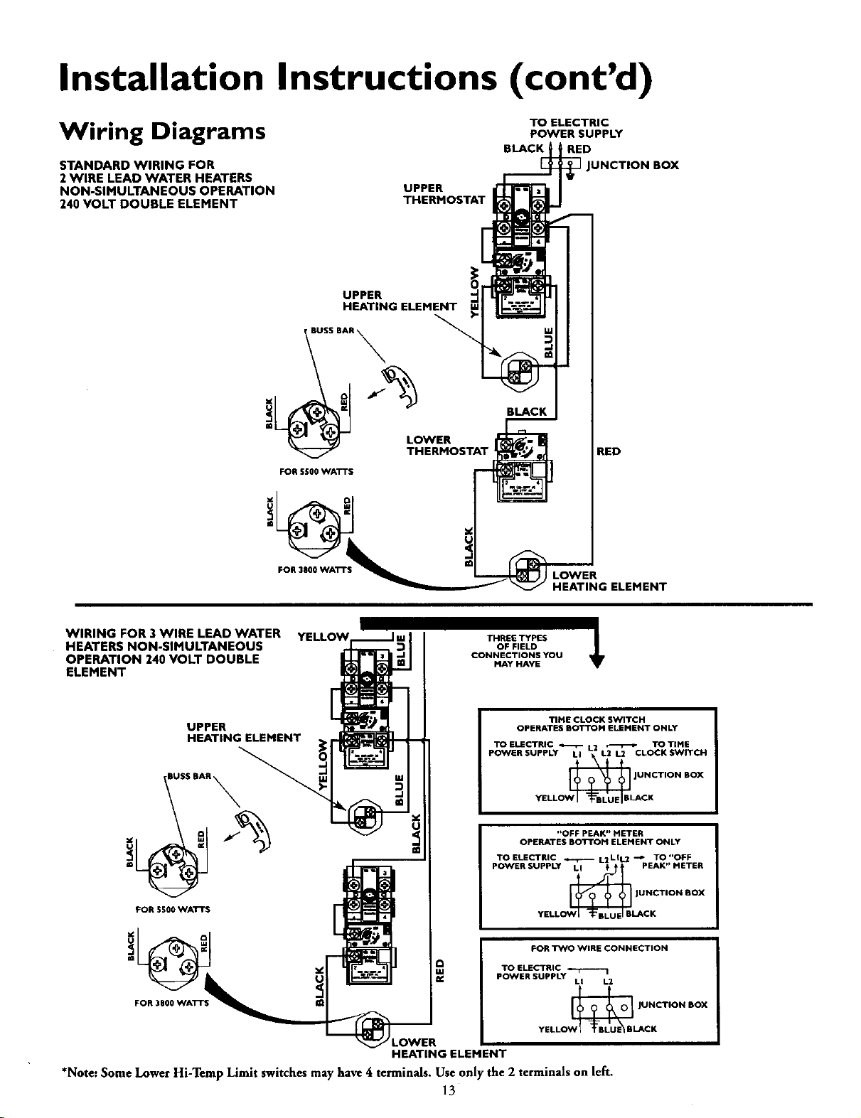
Wiring Diagrams
STANDARD WIRING FOR
2WIRE LEAD WATER HEATERS
NON-SIMULTANEOUS OPERATION
240 VOLT DOUBLE ELEMENT
UPPER
THERMOSTAT
TO ELECTRIC
POWER SUPPLY
BLACK, ' RED
JUNCTION BOX
UPPER
HEATING ELEMENT
\
J
FOR SSO0 WATTS
FOR 3800 WAT'I
BLACK
LOWER
RED
ELEMENT
WIRING FOR 3WIRE LEAD WATER
HEATERS NON-SIMULTANEOUS
OPERATION 240 VOLT DOUBLE
ELEMENT
THREE TYPES
OF FIELD
CONNECTIONS YOU
MAY HAVE
UPPER
HEATING ELEMENT
$S BAR
FOR SS00 WATTS
FOR 3800 WATTS
TIME CLOCK SWITCH
OPERATES BOTTOM ELEMENT ONLY
TOELECTRIC _ L2 _ TOTIME
POWER SUPPLY LI L2 L2 CLOCK SWITCH
JOWI'_B LA NCTION BOX
yELL CK
"OFF PEAK" METER
OPERATES BOTTOM ELEMENT ONLY
TOELECTRIC _ L2LIL2 -'P TO"OFF
POWER SUPPLY LI ! PEAK" METER
_ JUNCTION BOX
YELL U_CK
@
FOR TWO WIRE CONNECTION
TO ELECTRIC 4"-I-'-"---I
POWER SUPPLY
LI L2
_ |UNCTION BOX
YELLO LACK
HEATINGELEMENT
*Note:Some Lower Hi-Temp Limit switches may have 4 terminals. Use only the 2 terminals on left
13
Installation Instructions (cont'd)
Wiring
_CAUTION
Never usethis water heater unlessit iscompletely full of
water. To prevent damage to the tank and heating ele-
ment, the tank must be filled with water. Water must
flow from the hot water faucet before turn ng on power.
You must provide all wiring of the proper size outside of the
water heater. You must obey local codes and electric company
requirements when you install this wiring.
If you are not familiar with electric codes and practices, or if you
have any doubt, even the slightest doubt, in your ability to con-
nect the wiring to this water heater, obtain the service of a com-
petent electrician. Contact your Sears salesperson to arrange for a
professional electrician.
AWARNING
WATER HEATERS EQUIPPED FOR ONE VOLTAGE
ONLY: This water heater is equipped for one type volt-
age only. Check the rating plate near the bottom access
panel for the correct voltage. DO NOT use this water
heater with any voltageother than the one shownon the
model rating plate. Failureto usethe correct voltagecan
cause problems which can result in DEATH, SERIOUS
BODILY INJURY,OR PROPERTY DAMAGE. If you have
any questionsor doubtsconsultyour electric company.
• ,CAUTION
If wiring from your fuse box or circuit breaker box was
aluminum for your old water heater, replace it with cop-
per wire. Ifyou wishto reusethe existingaluminum wire,
havethe connectionat the water heater made bya com-
petent electrician. Contact your Sears salesperson to
arrangefor a professionalelectrician.
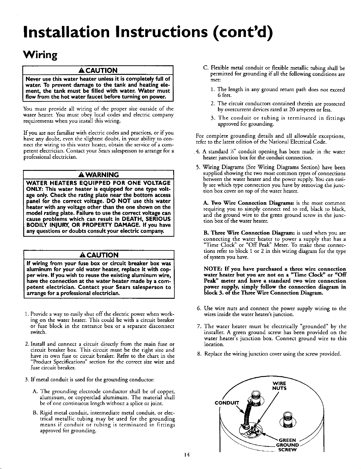
C. Flexible metal conduit or flexible metallic tubing shall be
permitted for grounding if all the following conditions are
met:
1. The length in any ground return path does not exceed
6 feet.
2. The circuit conductors contained therein are protected
by overcurrent devices rated at 20 amperes or less.
3. The conduit or tubing is terminated in fittings
approved for grounding.
For complete grounding details and all allowable exceptions,
refer to the latest edition of the National Electrical Code.
,4. A standard _" conduit opening has been made in the water
heater junction box for the conduit connection.
5. Wiring Diagrams (See Wiring Diagrams Section) have been
supplied showing the two most common types of connections
between the water heater and the power supply. You can easi-
ly see which type connection you have by removing the junc-
tion box cover on top of the water heater.
A. Two Wire Connection Diagrams: is the most common
requiring you to simply connect red to red, black to black,
and the ground wire to the green ground screw in the junc-
tion box of the water heater.
B. Three Ware Connection Diagram: is used when you are
connecting the water heater to power a supply that has a
"Time Clock" or "Off Peak" Meter. To make these connec-
tions refer to block 1 or 2 in this wiring diagram for the type
of system you have.
NOTE: If you have purchased a three wire connection
,heater but you are not on a "Time Clock" or "Off
_a_r, meter and have a standard two wire connection
_ower supply, simply follow the connection diagram in
lock 3. of the Three Wire Connection Diagram.
1. Provide a way to easily shut off the electric power when work-
ing on the water heater. This could be with a circuit breaker
or fuse block in the entrance box or a separate disconnect
switch.
2. Install and connect a circuit directly from the main fuse or
circuit breaker box. This circuit must be the right size and
have its own fuse or circuit breaker. Refer to the chart in the
"Product Specifications" section for the correct size wire and
fuse circuit breaker.
6. Use wire nuts and connect the power supply wiring to the
wires inside the water heater's junction.
7. The water heater must be electrically "grounded" by the
installer. A green ground screw has been provided on the
water heater's junction box. Connect ground wire to this
location.
8. Replace the wiring junction cover using the screw provided.
3. If metal conduit is used for the grounding conductor:
A. The grounding electrode conductor shall be of copper,
aluminum, or copperclad aluminum. The material shall
be of one continuous length without a splice or joint.
B. Rigid metal conduit, intermediate metal conduit, or elec-
trical metallic tubing may be used for the grounding
means if conduit or tubing is terminated in fittings
approved for grounding.
CONDUIT
SCREW
14
Installation Instructions (cont'd)
Installation Checklist
• Whether or not the element conversion is made, the model
raring plate must be marked• Using a hard point ink pen,
check the appropriate block within the model rating plate,
which is located adjacent to the lower access panel.
• Is the fuse or circuit breaker size correct as shown in the chart
in the "Product Specifications" section?
• Are the wires from the circuit breaker or fuse service to the
water heater's junction box on the correct wire size (gauge) as
shown in the chart in the "Product Specifications" section?
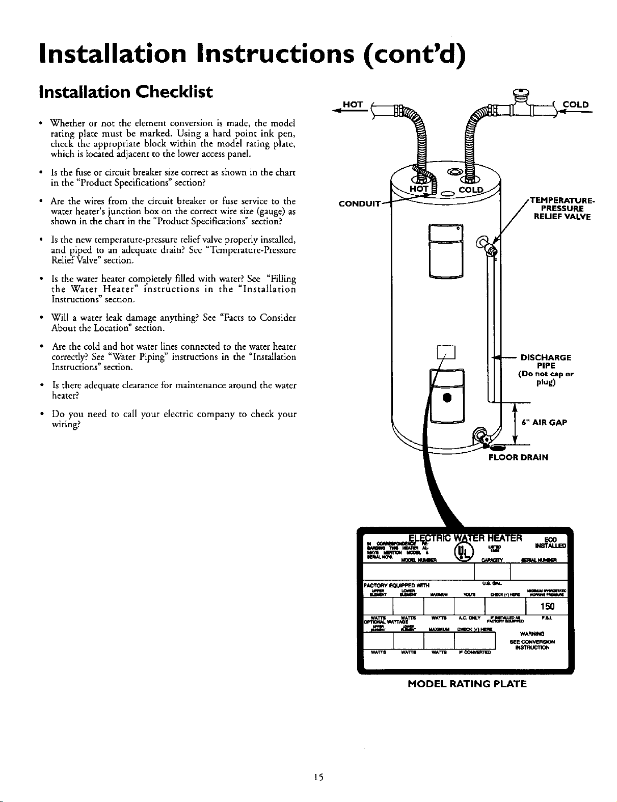
• Is the new temperature-pressure relief valve properly installed,
and piped to an adequate drain? See Temperature-Pressure
Relief Valve" section.
• Is the water heater completely filled with water? See _Filling
the Water Heater" instructions in the _Installation
Instructions section.
• Will a water leak damage anything? See "Facts to Consider
About the Location" section•
• Are the cold and hot water lines connected to the water heater
correctly? See "Water Piping" instructions in the "Installation
Instructions section•
• Is there adequate clearance for maintenance around the water
heater?
• Do you need to call your electric company to check your
wiring?
HOT COLD
TEMPERATURE.
PRESSURE
RELIEF VALVE
DISCHARGE
PIPE
(Do not cap or
plug)
6" AIR GAP
FLOOR DRAIN
MODEL RATING PLATE
15
Service and Adjustment
Temperature Regulation
AWARNING
HOTTER WATER CAN SCALD: Water heaters are
intended to produce hot water. Water heated to a tem-
perature which will satisfyspaceheating, clothes wash-
ing, dish washing, and other sanitizing needs can scald
and permanently injure you upon contact. Some people
are more likely to be permanently injured by hot water
than others. These include the elderly, children, the
infirm, or physically/mentally handicapped. If anyone
using hot water in your home fits into one of these
groupsor if there isa local code or state law requiring a
certain temperature water at the hot water tap, then
you must take special precautions. In addition to using
the lowest possible temperature setting that satisfies
your hot water needs, a means such as a mixing valve,
shallbe usedat the hot water taps usedbythese people
or at the water heater. Mixing valves are available at
plumbingsupplyor hardware stores. Followmanufactur-
ers instructions for installation of the valves. Before
changingthe factory setting on the thermostat, read the
"Temperature Regulation"sectionin this manual.
AWARNING
Never allow small children to usea hot water tap, or to
draw their own bath water. Never leavea child or handi-
cappedperson unattended in a bathtub or shower.
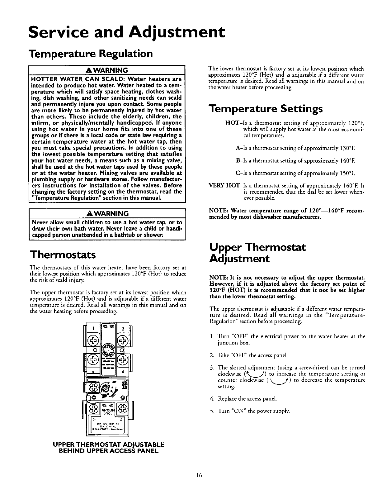
Thermostats
The thermostats of this water heater have been factory set at
their lowest position which approximates 120°F (Hot) to reduce
the risk of scald injury.
The upper thermostat is factory set at its lowest position which
approximates 120°F (Hot) and is adjustable if a different water
temperature is desired. Read all warnings in this manual and on
the water heating before proceeding.
The lower thermostat is factory set at its lowest position which
approximates 120°F (Hot) and is adjustable if a different water
temperature is desired. Read all warnings in this manual and on
the water heater before proceeding.
Temperature Settings
HOT-Is a thermostat setting of approximately 120°E
which will supply hot water at the most economi-
cal temperatures.
A-Is a thermostat setting of approximately 130°E
B-Is a thermostat setting of approximately 140°E
C-Is a thermostat setting of approximately 150°E
VERY HOT-Is a thermostat setting of approximately 160°E It
is recommended that the dial be set lower when-
ever possible.
NOTE: Water temperature range of 120°--140°F recom-
mended by most dishwasher manufacturers.
Upper Thermostat
Adjustment
NOTE: It is not necessary to adjust the upper thermostat.
However, if it is adjusted above the factory set point of
120°F (HOT) is is recommended that it not be set higher
than the lower thermostat setting.
The upper thermostat is adjustable if a different water tempera-
ture is desired. Read all warnings in the "Temperature-
Regulation" section before proceeding.
1, Turn "OFF" the electrical power to the water heater at the
junction box.
2. Take "OFF" the access panel.
3. The slotted adjustment (using a screwdriver) can be turned
clockwise (*%..___) to increase the temperature setting or
cou.nter clockwise (_..._) to decrease the temperature
setting.
4. Replace the access panel.
5. Turn "ON" the power supply.
UPPER THERMOSTAT ADJUSTABLE
BEHIND UPPER ACCESS PANEL
16
Service Adjustment (cont'd)
Lower Thermostat
Adjustment
The lower thermostat is adjustable if a different water tempera-
ture is desired. Read all warnings in the "Temperature-
Regulation" section before proceeding.
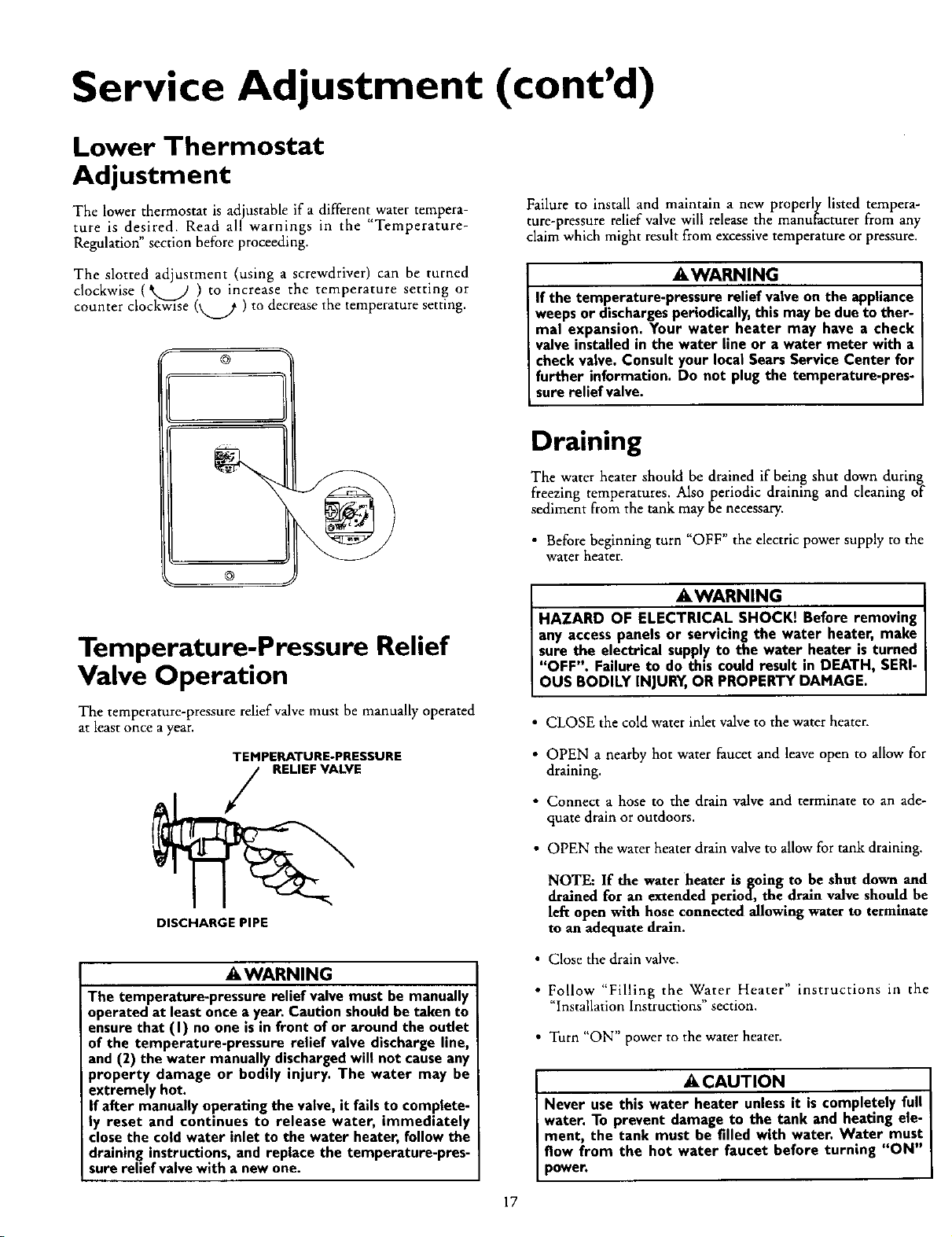
The slotted adjustment (using a screwdriver) can be turned
clockwise (',,, fl ) to increase the temperature setting or
counter clock_i-se (_ ) to decrease the temperature setting.
@
Failure to install and maintain a new properly listed tempera-
ture-pressure relief valve will release the manufacturer from any
claim which might result from excessivetemperature or pressure.
AWARNING
If the temperature-pressure relief valveon the appliance
weepsor dischargesperiodically,this may bedue to ther-
mal expansion. Your water heater may have a check
valve installedin the water line or a water meter with a
checkvalve. Consult your local SearsService Center for
further information. Do not plug the temperature-pres-
sure relief valve.
®
@
Temperature-Pressure Relief
Valve Operation
The temperature-pressure relief valve must be manually operated
at least once a year.
TEMPERATURE-PRESSURE
RELIEF VALVE
DISCHARGE PIPE
AWARNING
The temperature-pressure relief valve must be manually
operated at leastonce a year. Caution shouldbe taken to
ensurethat (I) no one isin front of or aroundthe outlet
of the temperature-pressure relief valve discharge line,
and (2) the water manually dischargedwill not causeany
property damage or bodily injury. The water may be
extremely hot.
If after manuallyoperating the valve, it fails to complete-
ly reset and continues to release water, immediately
closethe cold water inlet to the water heater, follow the
draining instructions, and replace the temperature-pres-
sure relief valvewith a new one.
Draining
The water heater should be drained if being shut down during
freezing temperatures. Also periodic draining and cleaning of
sediment from the tank may be necessary.
• Before beginning turn "OFF" the electric power supply to the
water heater.
AWARNING
HAZARD OF ELECTRICAL SHOCK! Before removing
any accesspanels or servicing the water heater, make
sure the electrical supply to the water heater isturned
"OFF". Failure to do this could result in DEATH, SERI-
OUS BODILY INJURY,OR PROPERTY DAMAGE.
• CLOSE the cold water inlet valve to the water heater.
• OPEN a nearby hot water faucet and leave open to allow for
draining.
• Connect a hose to the drain valve and terminate to an ade-
quate drain or outdoors.
• OPEN the water beater drain valve to allow for tank draining.
NOTE: If the water heater is going to be shut down and
drained for an extended period, the drain valve should be
lefx open with hose connected allowing water to terminate
to an adequate drain.
• Close the drain valve,
• Follow "Filling the Water Heater" instructions in the
"Installation Instructions" section.
• Turn "ON" power to the water heater.
ACAUTION
Never use this water heater unlessit iscompletely full
water. To prevent damage to the tank and heating ele-
ment, the tank must he filled with water. Water must
flow from the hot water faucet before turning "ON"
power.
17
Service and Adjustment (cont'd)
Element Cleaning/
Replacement
NOTE: These instructions are written for element cleaning
and dement replacement for the lower dement. If it is neces-
sary to clean or replace the upper element, then repeat these
instructions.
To remove the element from your tank in order to clean or
replace it:
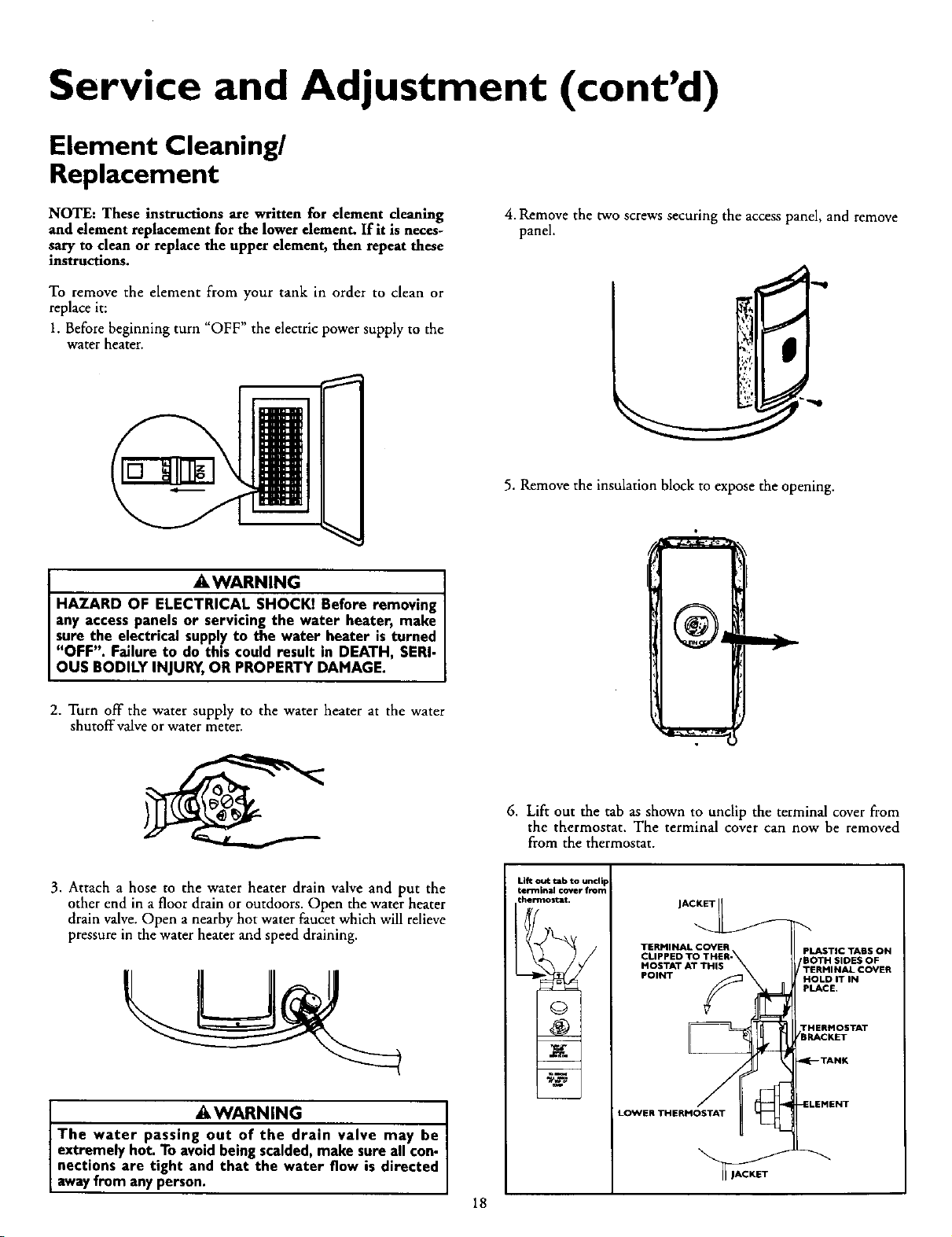
1. Before beginning turn "OFF" the electric power supply to the
water heater.
]
4. Remove the two screws securing the access panel, and remove
panel.
5. Remove the insulation block to expose the opening.
AWARNING
i
HAZARD OF ELECTRICAL SHOCKI Before removing
any access panels or servicing the water heater, make
sure the electrical supply to the water heater is turned
"OFF". Failure to do this could result in DEATH, SERI-
OUS BODILY INJURY, OR PROPERTY DAMAGE.
2. Turn off the water supply to the water heater at the water
shutoffvalve or water meter.
6. Lift out the tab as shown to unclip the terminal cover from
the thermostat. The terminal cover can now be removed
from the thermostat.
3. Attach a hose to the water heater drain valve and put the
other end in a floor drain or outdoors. Open the water heater
drain valve. Open a nearby hot water faucet which will relieve
pressure in the water heater and speed draining.
AWARNING
The water passing .out of the drain valve may be
extremely hot. To avoid being scalded, make sure all con-
nections are tight and that the water flow is directed
away from any person.
Uft out tab to uncli F
terminal cover from
thermostat.
TERMINAL COVER
CLIPPED TO THER-
MOSTAT AT THIS
POINT y_
_A
41
LOWER THERMOSTAT 41
PLASTIC TABS ON
BOTH SIDES OF
/TERMINAL COVER
HOLD IT IN
PLACE.
THERMOSTAT
/BRACKET
_--- TANK
-ELEMENT
18
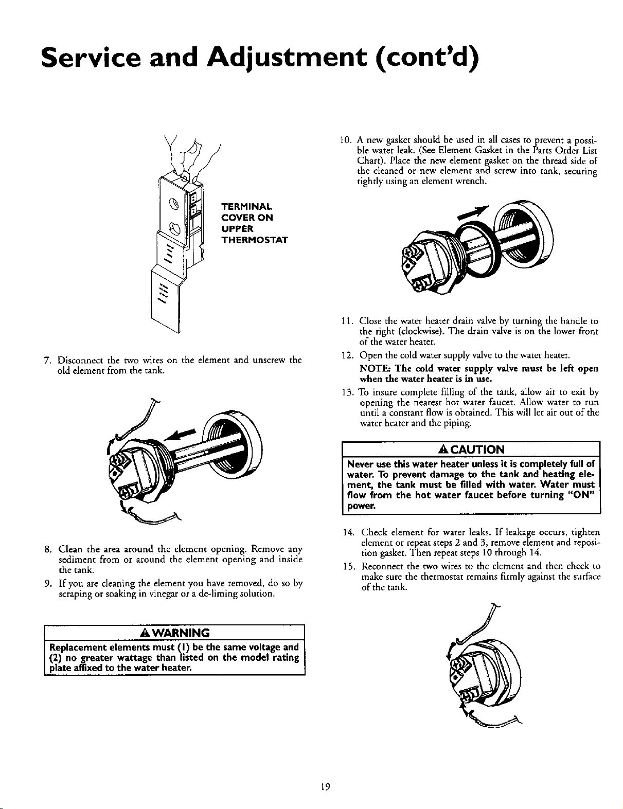
Service and Adjustment (cont'd)
TERMINAL
COVER ON
UPPER
THERMOSTAT
10. A new gasket should be used in all cases to prevent a possi-
ble water leak. (See Element Gasket in the Parts Order List
Chart). Place the new element gasket on the thread side of
the cleaned or new element and screw into tank, securing
tightly using an element wrench.
7. Disconnect the two wires on the element and unscrew the
old element from the tank.
8. Clean the area around the element opening. Remove any
sediment from or around the element opening and inside
the tank.
9. If you are cleaning the element you have removed, do so by
scraping or soaking in vinegar or a de-liming solution.
AWARNING
Replacement elements must (I) be the samevoltage and
(2) no greater wattage than listed on the model rating
pate affixedto the water heater.
11. Close the water heater drain valve by turning the handle to
the right (clockwise). The drain valve is on the lower front
of the water heater.
12. Open the cold water supply valve to the water heater.
NOTE: The cold water supply valve must be left open
when the water heater is in use.
13. To insure complete filling of the tank, allow air to exit by
opening the nearest hot water faucet. Allow water to run
until a constant flow is obtained. This will let air out of the
water heater and the piping.
A CAUTION
Never use this water heater unless it is completely full of
water. To prevent damage to the tank and heating ele-
ment, the tank must be filled with water. Water must
flow from the hot water faucet before turning "ON"
power
14. Check element for water leaks. If leakage occurs, tighten
element or repeat steps 2 and 3, remove element and reposi-
tion gasket. Then repeat steps 10 through 14.
15. Reconnect the two wires to the element and then check to
make sure the thermostat remains firmly against the surface
of the tank.
19
Service and Adjustment (cont'd)
Element Cleaning/
Replacement (cont'd)
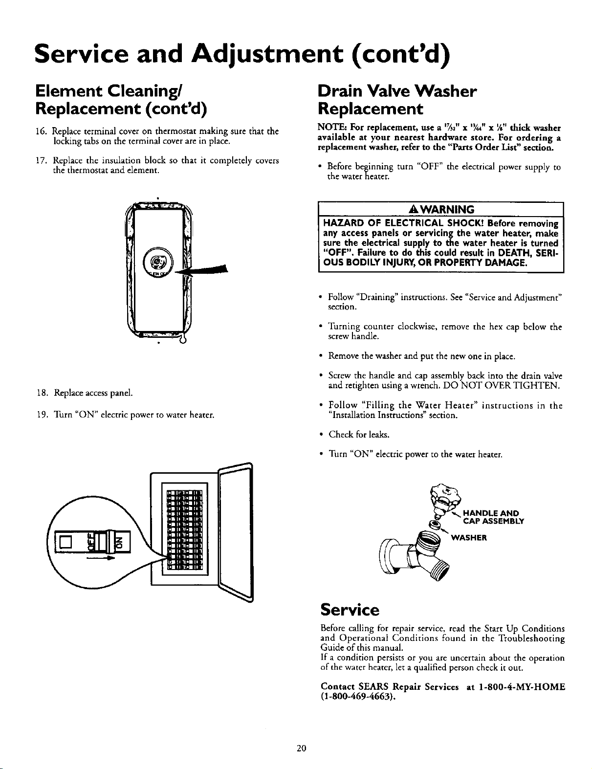
16. Replace terminal cover on thermostat making sure that the
locking tabs on the terminal cover are in place.
17. Replace the insulation block so that it completely covers
the thermostat and element.
Drain Valve Washer
Replacement
NOTE: For replacement, use a *_2" x ,3/,, x ¼" thick washer
available at your nearest hardware store. For ordering a
replacement washer, refer to the "Parts Order List" section.
• Before beginning turn "OFF" the electrical power supply to
the water heater.
18. Replace access panel.
19. Turn "ON" electric power to water heater.
AWARNING
HAZARD OF ELECTRICAL SHOCKI Before removing
any access panels or servicing the water heater, make
sure the electrical supplyto the water heater is turned
"OFF". Failure to do this could result in DEATH, SERI-
OUS BODILY INJURY,OR PROPERTY DAMAGE.
• Follow "Draining" instructions. See "Service and Adjustment"
section.
• Turning counter clockwise, remove the hex cap below the
screw handle.
• Remove the washer and put the new one in place.
• Screw the handle and cap assembly back into the drain valve
and retighten using a wrench. DO NOT OVER TIGHTEN.
• Follow !'Filling the Water Heater" instructions in the
"Installation Instructions" section.
• Check for leaks.
• Turn "ON" electric power to the water heater.
_ HANDLE AND
CAP ASSEMBLY
WASHER
Service
Before calling for repair service, read the Start Up Conditions
and Operational Conditions found in the Troubleshooting
Guide of this manual.
If a condition persists or you are uncertain about the operation
of the water heater, let a qualified person check it out.
Contact SEARS Repair Services at 1-800-4-MY-HOME
(1-800-469-4663).
20

Troubleshooting Guide
Start Up Conditions
THERMAL EXPANSION
Water supply systems may, because of such events as high line
pressure, frequent cut-offs, the effects of water hammer among
others, have installed devices such as pressure reducing valves,
check valves, back flowpreventers, erc...to control these types of
problems. When these devices are not equipped with an internal
by-pass, and no other measures are taken, the devices cause the
water system to be closed. As water is heated, it expands (ther-
mal expansion) and closed systems do not allow for the expan-
sion of heated water.
The water within the water heater tank expands as it is heated and
increases the pressure of the water system. If the relieving point of
the water heater s temperature-pressure relief valve is reached, the
valve will relieve the excesspressure. The temperature-pressure
relief valve is not intendedfor the constant relief of thermal
expansion. This is an unacceptable condition and must be cor-
rected.
It is recommended that any devices installed which could create a
closed system have a by-pass and/or the system have an expan-
sion tank to relieve the pressure built by thermal expansion.
Thermal expansion tanks are available from Sears stores and
through the Sears Service Centers. Contact the local plumbing
inspector, water supplier and/or the Sears Service Center for
assistance in controlling these situations.
Thermal Expansion Tank Specifications
Model Tank Capacity Dimensions in Inches Pipe Fitting
Number In Gallons Diameter Length On Tank
153.331020 2 8inches 12_inches _" Male
153.331050 5 11 inches 14_ inches _" Male
NOT COLD
HOT
WATER HEATER
COLD WATER
INLET FITTING
WATER HEATER (3)
COLD WATER PRESSURE
INLET FITTING REDUCING
VALVEWITH
BY-PASS
(2)
PRESSURE GAUGE
WATER
SHUTOFF
RECOMMENDED INSTALLATION
(VERTICAL MOUNTING)
FLOOR, CEILING
JOIST,ETC.
STRAPPING
(i)
EXPANSION
(3)
PRESSURE
REDUCING INLETCOLD
VALVEWITH WATER
BY-PASS SHUTOFF
Expansion Tank Sizing Chart
Water Heater Capacity (Gallons)
Expansion
Tank
Capacity
Needed
Inlet*
Water
Pressure
40psi
50psi
60psi
70psi
80psi
30 _ 40 50 b 66 82
2 2 2 5 5
2 2 2 5 5
2 2 5 5 5
2 2 5 5 5
2 5 5 5 5
*Highest recorded inlet water pressure in a 24 hour period or
regulated water pressure.
NOTE= Expansion tanks are pre-charged with a 40 psi air
charge. If the inlet water pressure is higher than 40 psi, the
expansion tank's air pressure must be adjusted to match that
pressure, bur must not be higher than 80 psi.
PRESSUREGAUGE
ALTERNATE RECOMMENDED
INSTALLATION
(HORIZONTAL MOUNTING)
STRANGE SOUNDS
Possible noises due to expansion and contraction of some metal
_arts during periods of heat-up and cool-down do not represent
armful or dangerous conditions.
21
Troubleshooting Guide
Operational Conditions
SMELLY WATER
In each water heater there is installed at least one anode rod (see
parts section) for corrosion protection of the tank. Certain water
conditions will cause a reaction between this rod and the water.
The most common complaint associated with the anode rod is
one of a "rotten egg smell". This odor is derived from hydrogen
sulfide gas dissolved in the water. The smell is the result of tour
factors which must all be present for the odor to develop:
a. a concentration of sulfate in the supply water.
b. little or no dissolved oxygen in the water.
c. a sulfate reducing bacteria within the water heater. (This
harmless bacteria is non-toxic to humans.)
d. an excess of active hydrogen in the tank. This is caused by
the corrosion protective action of the anode.
Smelly water may be eliminated or reduced in some water heater
models by replacing the anode(s) with one of less active material,
and then chlorinating the water heater tank and all hot water
lines. Contact the local Sears Service Center for further informa-
tion concerning an Anode Replacement Kit #9001453 and this
Chlorination Treatment.
If the smelly water persists after the anode replacement and chlo-
rination treatment, we can only suggest that continuous chlori-
nation and filtering conditioning equipment be considered to
eliminate the water problem.
Do not remove the anode leaving the tank unprotected. By
doing so, all warranty on the water heater tank is voided.
RUMBLING NOISE
In some water areas, scale or mineral deposits will build up on
your heating elements. This buildup will cause a rumbling noise.
Follow "Element Cleaning/Replacement" instructions to clean
and replace the elements.
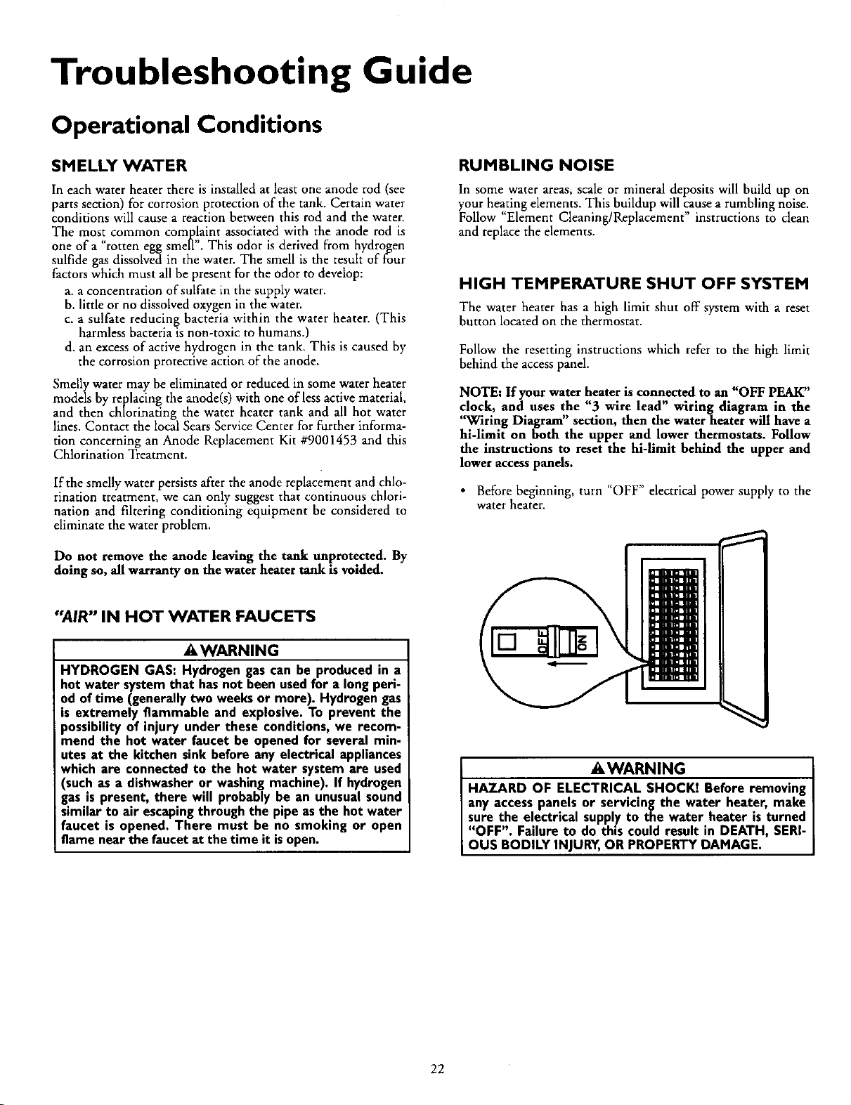
HIGH TEMPERATURE SHUT OFF SYSTEM
The water heater has a high limit shut off system with a reset
button located on the thermostat.
Follow the resetting instructions which refer to the high limit
behind the access panel.
NOTE: If your water heater is connected to an "OFF PEAK"
clock, and uses the "3 wire lead" wiring diagram in the
"Wiring Diagram" section, then the water heater will have a
hi-limit on both the upper and lower thermostats. Follow
the instructions to reset the hi-limit behind the upper and
lower access panels.
• Before beginning, turn "OFF" electrical power supply to the
water heater.
"AIR" IN HOT WATER FAUCETS
AWARNING
HYDROGEN GAS: Hydrogen gas can be produced in a
hot water system that hasnot been usedfor a long peri-
od of time (generally two weeksor more). Hydrogen gas
is extremely flammable and explosive. To prevent the
possibility of injury under these conditions, we recom-
mend the hot water faucet be opened for several min-
utes at the kitchen sink before any electrical appliances
which are connected to the hot water system are used
(such as a dishwasheror washingmachine). If hydrogen
gas is present, there will probably be an unusualsound
similar to air escapingthrough the pipe asthe hot water
faucet is opened. There must be no smoking or open
flame near the faucetat the time it isopen.
AWARNING
HAZARD OF ELECTRICAL SHOCK! Before removing
any accesspanels or servicing the water heater, make
sure the electrical suppl.yto the water heater is turned
"OFF". Failure to do th,s could result in DEATH, SERI-
OUS BOD LY NJURY,OR PROPERTY DAMAGE.
22
Troubleshooting Guide (cont'd)
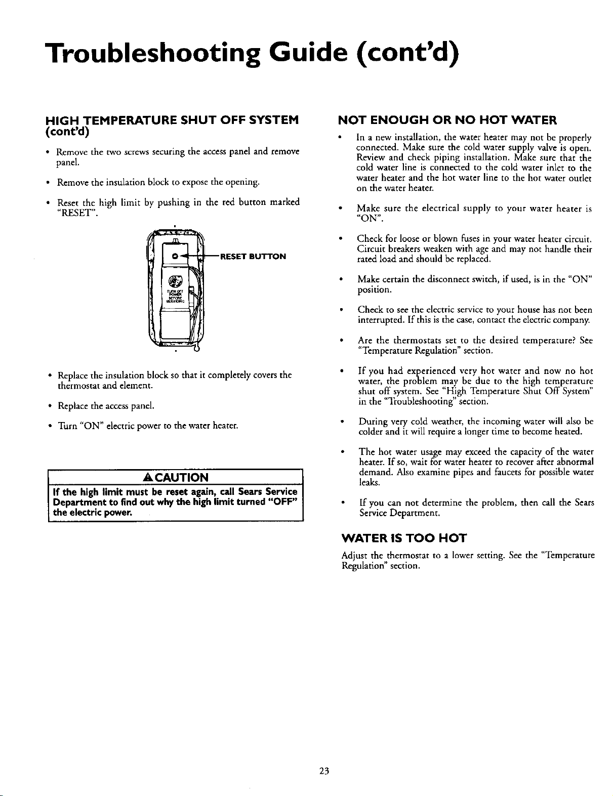
HIGH TEMPERATURE SHUT OFF SYSTEM
(cont'd)
• Remove the two screws securing the access panel and remove
panel.
• Remove the insulation block to expose the opening.
• Reset the high limit by pushing in the red button marked
"RESET".
--RESET BUTTON
• Replace the insulation block so that it completely covers the
thermostat and element.
• Replace the access panel.
• Turn "ON" electric power to the water heater.
ACAUTION
If the high limit must be reset again, call Sears Service
Department to findout whythe high limit turned "OFF"
the electric power.
NOT ENOUGH OR NO HOT WATER
In a new installation, the water heater may not be properly
connected. Make sure the cold water supply valve is open.
Review and check piping installation. Make sure that the
cold water line is connected to the cold water inlet to the
water heater and the hot water line to the hot water outlet
on the water heater.
Make sure the electrical supply to your water heater is
"ON".
Check for loose or blown fuses in your water heater circuit.
Circuit breakers weaken with age and may not handle their
rated load and should be replaced.
Make certain the disconnect switch, if used, is in the "ON"
position.
Check to see the electric service to your house has not been
interrupted. If this is the case, contact the electric company.
Are the thermostats set to the desired temperature? See
"Temperature Regulation" section.
If you had experienced very hot water and now no hot
water, the problem may be due to the high temperature
shut off system. See H!gh Temperature Shut Off System
in the Troubleshooting section.
During very cold weather, the incoming water will also be
colder and it will require a longer time to become heated.
The hot water usage may exceed the capacity of the water
heater. If so, wait for water heater to recover after abnormal
demand. Also examine pipes and faucets for possible water
leaks.
If you can not determine the problem, then call the Sears
Service Department.
WATER IS TOO HOT
Adjust the thermostat to a lower setting. See the "Temperature
Regulation" section.
23
Troubleshooting Guide (cont'd)
Leakage Checkpoints
Use this guide to check a "Leaking" water heater. Many suspect-
ed "Leakers" are not leaking tanks. Often the source of the water
can be found and corrected.
If you are not thoroughly familiar with electric codes, the water
heater, and safety practices, contact your local Sears Service
Center to check the water heater.
A, CAUTION
Read this manual first, then before checking the water
heater make sure the electric supply has been turned
"OFF", and never turn the electric supply "ON" before
the tank iscompletely full ofwater.
• , CAUTION
Never usethis water heater unlessit iscompletely full of
water. To prevent damage to the tank and heating ele-
ment, the tank mustbefilled with water. The water must
flow from the hot water faucet before turning "ON"
power.
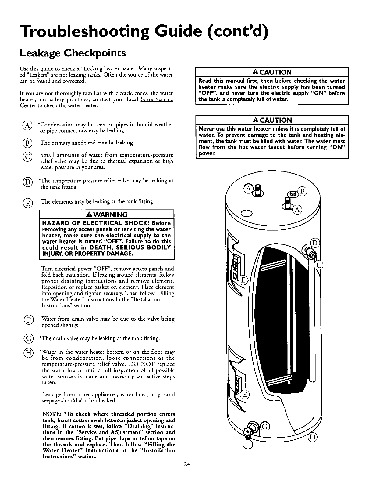
(_) *Condensation be seen on pipes in humid weather
may
or pipe connections may be leaking.
®
©
The primary anode rod may be leaking.
Small amounts of water from temperature-pressure
relief valve may be due to thermal expansion or high
water pressure in your area.
(_) *The temperature-pressure relief valve may be leaking at
the tank fitting.
®
The elements may be leaking at the tank fitting.
_,WARNING
HAZARD OF ELECTRICAL SHOCK! Before
removing anyaccesspanelsor servicingthe water
heater, make sure the electrical supply to the
water heater is turned "OFF". Failure to do this
could result in DEATH, SERIOUS BODILY
INJURY,OR PROPERTY DAMAGE.
Turn electrical power "OFF", remove access panels and
fold back insulation. If leaking around elements, follow
proper draining instructions and remove element.
Reposition or replace gasket on element. Place e!ement
into opening and tighten securely. Then follow Filling
the Water Heater" instructions in the "Installation
Instructions" section.
®
©
®
Water from drain valve may be due to the valve being
opened slightly.
*The drain valve may be leaking at the tank fitting.
*Water in the water heater bottom or on the floor may
be from condensation, loose connections or the
temperature-pressure relief valve. DO NOT replace
the water heater until a full inspection of all possible
water sources is made and necessary corrective steps
taken.
Leakage from other appliances, water lines, or ground
seepage should also be checked.
NOTE: *To check where threaded portion enters
tank, insert cotton swab between jacket opening and
fitting. If cotton is wet, follow "Draining" instruc-
tions in the "Service and Adjustment" section and
then remove fitting. Put pipe dope or teflon tape on
the threads and replace. Then follow "Filling the
Water Heater" instructions in the "Installation
Instructions" section.
24

Notes
25
Parts Order List
KENMORE POWER MISER TM 6 ELECTRIC WATER HEATERS
MODEL NUMBERS:
153.316152 30Gal. Short
153.316153 30Gal. Short
153.316252 40Gal. Short
153.316253 40 GM. Sho_
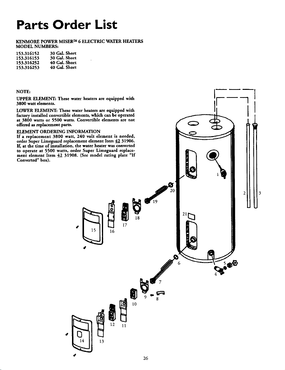
NOTE:
UPPER ELEMENT: These water heaters are equipped with
3800 watt elements.
LOWER ELEMENT: These water heaters are equipped with
_actory installed convertible elements, which can be operated
at 3800 watts or 5500 watts. Convertible elements are not
offered as replacement parts.
ELEMENT ORDERING INFORMATION
If a replacement 3800 watt, 240 volt element is needed,
order Super Limeguard replacement element Item 42 31906.
If, at the time of installation, the water heater was converted
to operate at 5500 watts, order Super Limeguard replace_
ment element Item 42 31908. (See model rating plate "If
Converted" box).
16
3
13
26
Parts Order List (cont'd)
KENMORE POWER MISER TM 6 ELECTRIC WATER HEATERS
MODEL NUMBERS:
153.316152 30 G_.Sho_
153.316153 30 GM. Sho_
153.316252 40Gal. Sho_
153.316253 40 G_.ShoR
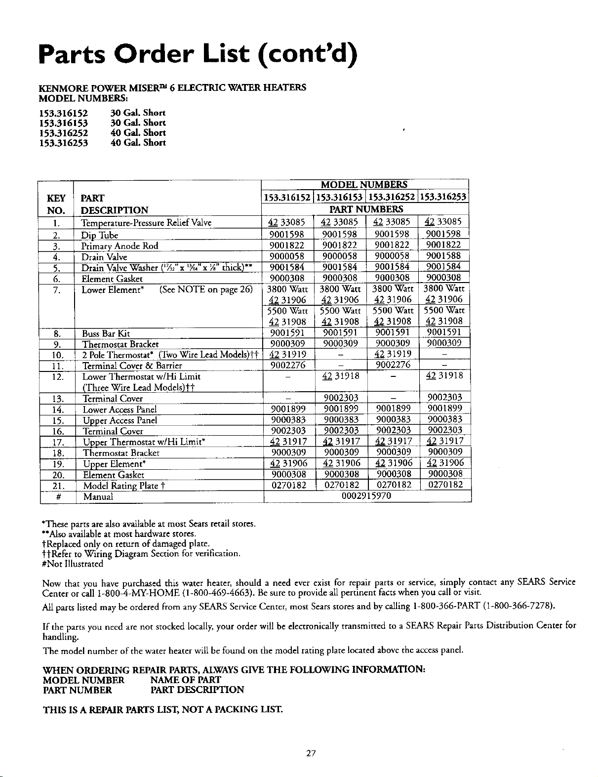
KEY PART
NO. DESCRIPTION
1. Temperature-Pressure Relief Valve
2. Dip Tube
3. Primary Anode Rod
4. Drain Valve
5. Drain Valve Washer (1_2" x lye,, x 7;' thick)**
6. Element Gasket
7. Lower Element* (See NOTE on page 26)
8. Buss Bar Kit
9. Thermostat Bracket
10. 2 Pole Thermostat* (Two Wire Lead Models)tt
11. Terminal Cover & Barrier
12. Lower Thermostat w/Hi Limit
(Three Wire Lead Models)_"i"
13. Terminal Cover
14. Lower Access Panel
15. Upper Access Panel
16. Terminal Cover
17. Upper Thermostat w/Hi Limit*
18. Thermostat Bracket
19. Upper Element*
20. Element Gasket
21. Model Rating Plate t
# Manual
MODEL NUMBERS
1153.316153 153.316252 153.316253
153.316152
PART NUMBERS
4233085 4233085
9001598 9001598
9001822 9001822
9000058 9000058
9001584 9001584
9000308 9000308
3800Watt 3800Watt
4231906 4231906
5500Watt 5500Watt
4231908 4231908
9001591 9001591
9000309 9000309
- 4231919
- 9002276
4231918
9002303
9001899 9001899
9000383 9000383
9002303 9002303
4231917 4231917
9000309 9000309
4231906 4231906
9000308 90003080270182 0270182
0002915970
4233085
9001598
9001822
9000058
9001584
90003O8
3800Watt
4231906
5500Watt
42 31908
9001591
9000309
4231919
9002276
9001899
9000383
9002303
4231917
9000309
4231906
9000308
0270182
4_2233085
9001598
9001822
9001588
9001584
90003O8
3800Watt
4231906
5500Watt
4231908
9001591
9000309
4231918
90023O3
9001899
9000383
9002303
4231917
90003O9
4231906
9000308
0270182
*These parts are also availableat most Sears retail stores.
**Alsoavailableat most hardware stores.
tReplaced only on return of damaged plate.
t'_Refer to Wiring Diagram Section for verification.
#Not Illustrated
Now that you have purchased this water heater, should a need ever exist for repair parts or service, simply contact any SEARS Service
Center or call 1-800-4-MY-HOME (1-800-469-4663). Be sure to provide all pertinent facts when you call or visit.
All parts listed may be ordered from any SEARS Service Center, most Sears stores and by calling 1-800-366-PART (1-800-366-7278).
If the parts you need are not stocked locally, your order will be electronically transmitted to a SEARS Repair Parts Distribution Center for
handling.
The model number of the water heater will be found on the model rating plate located above the access panel.
WHEN ORDERING REPAIR PARTS,ALWAYSGIVE THE FOLLOWING INFORMATION:
MODEL NUMBER NAME OF PART
PART NUMBER PART DESCRIPTION
THIS IS A REPAIR PARTS LIST, NOT A PACKING LIST.
27
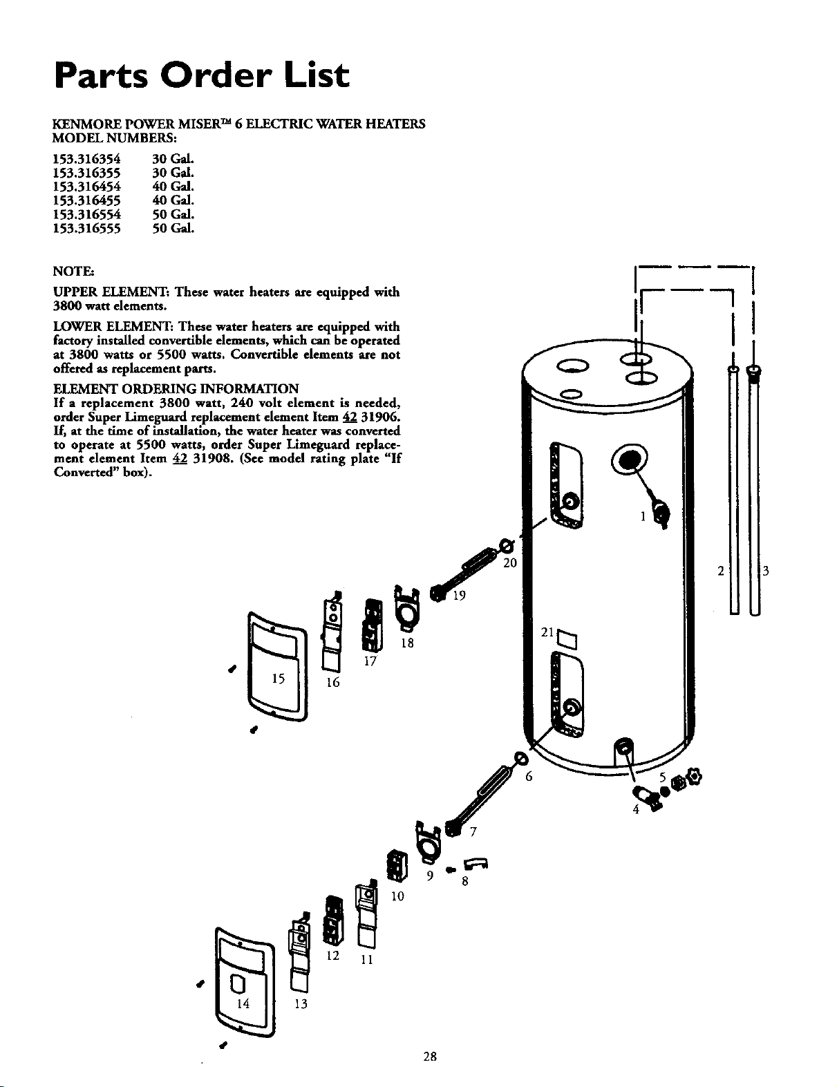
Parts Order List
KENMORE POWER MISERTM 6 ELECTRIC WATER HEATERS
MODEL NUMBERS:
153.316354 30Gal.
153.316355 30G_.
153.316454 40Gal.
153.316455 40Gal.
153.316554 50Gal.
153.316555 50Gal.
NOTE:
UPPER ELEMENT: These water heaters are equipped with
3800 watt elements.
LOWER ELEMENT: These water heaters are equipped with
factory installed convertible elements, which can be operated
at 3800 watts or 5500 watts. Convertible elements are not
offered as replacement parts.
ELEMENT ORDERING INFORMATION
If a replacement 3800 watt, 240 volt element is needed,
order Super Limeguard replacement element Item 42 31906.
If, at the time of installation, the water heater was_onverted
to operate at 5500 watts, order Super Limeguard replace-
ment element Item 42 31908. (See model rating plate "If
Converted" box).
16
7
13
28
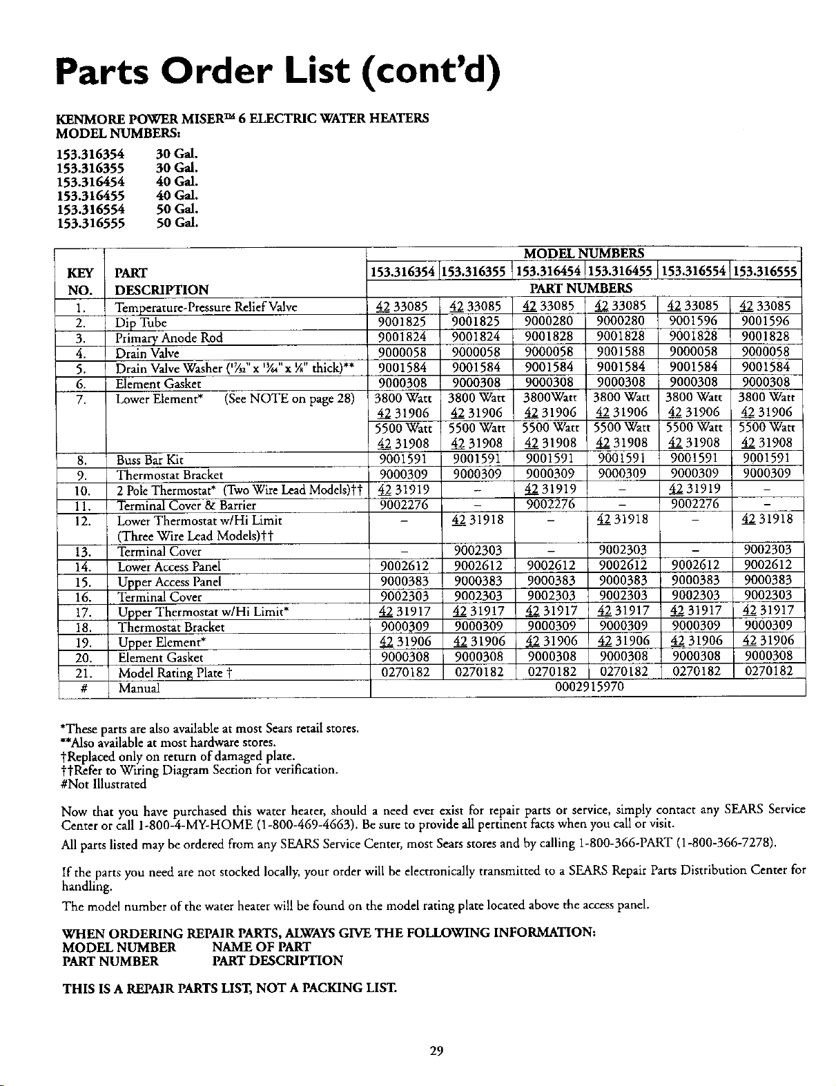
Parts Order List (cont'd)
KENMORE POWER MISER TM 6 ELECTRIC WATER HEATERS
MODEL NUMBERS:
153.316354 30G_.
153.316355 30G_,
153.316454 40 G_.
153.316455 40 G_.
153.316554 50G_.
153.316555 50G_.
KEY PART
NO. DESCRIPTION
1. Temperature-Pressure Relief Valve
2. Dip Tube
3. Primary Anode Rod
4. Drain Valve
5. Drain Valve Washer (*%;' x 'Yd' x X" thick)**
6. Element Gasket
7. Lower Element* (See NOTE on page 28)
8. Buss Bar Kit
9. Thermostat Bracket
10. 2 Pole Thermostat* (Two Wire Lead Models)tt
11. Terminal Cover & Barrier
12. Lower Thermostat w/Hi Limit
(Three Wire Lead Models)t1
13. Terminal Cover
14. Lower Access Panel
15. Upper Access Panel
16. Terminal Cover
17. Upper Thermostat w/Hi Limit*
18. Thermostat Bracket
19. Upper Element*
20. Element Gasket
21. Model Rating Plate 1"
# Manual
153.316354!153.316355 153.316554 153.316555
4233085 4233085
9001825 9001825
9001824 9001824
9000058 9000058
9001584 9001584
9000308 9000308
$800Watt 3800Wa_
4231906 4231906
5500Watt 5500Watt
4231908 4231908
9001591 9001591
9000309 9000309
4231919
9002276
- 4231918
- 9002303
9002612 9002612
9000383 9000383
9002303 9002303
4231917 4231917
9000309 9000309
4231906 4231906
9000308 9000308
0270182 0270182
MODEL NUMBERS
153.3164541153.316455
PART NUMBERS
4233085 4233085
9000280 9000280
9001828 9001828
9000058 9001588
9001584 9001584
9000308 9000308
3800Watt 3800Watt
4231906 4231906
5500Watt 5500Watt
4231908 4231908
9001591 9001591
9000309 9000309
4231919 -
9002276 -
- 4231918
- 9002303
9002612 9002612
9000383 9000383
9002303 9002303
4231917 4231917
9000309 9000309
4231906 4231906
9000308 9000308
0270182 0270182
0002915970
4233O85
9001596
9001828
9000058
9001584
9O00308
3800Watt
4231906
5500Watt
4231908
9001591
9000309
4231919
9002276
9002612
9000383
9002303
4231917
900O309
4231906
9000308
0270182
4233085
9001596
9001828
9000058
9001584
9000308
3800Watt
4231906
5500Watt
4231908
9001591
9000309
4231918
9002303
9002612
9000383
9002303
4231917
9O00309
4231906
9000308
0270182
*These parts are also available at most Sears retail stores.
**Also available at most hardware stores.
i'Replaced only on return of damaged plate.
t?Refer to Wiring Diagram Section for verification.
#Not Illustrated
Now that you have purchased this water heater, should a need ever exist for repair parts or service, simply contact any SEARS Service
Center or call 1-800-4-MY-HOME (1-800-469-4663). Be sure to provide all pertinent facts when you call or visit.
All parts listed may be ordered from any SEARS Service Center, most Sears stores and by calling 1-800-366-PART (1-800-366-7278).
If the parts you need are not stocked locally, your order will be electronically transmitted to a SEARS Repair Parts Distribution Center for
handling.
The model number of the water heater will be found on the model rating plate located above the access panel.
WHEN ORDERING REPAIR PARTS, ALWAYSGIVE THE FOLLOWING INFORMATION:
MODEL NUMBER NAME OF PART
PARTNUMBER PART DESCRIPTION
THIS IS A REPAIR PARTS LIST, NOT A PACKING LIST.
29
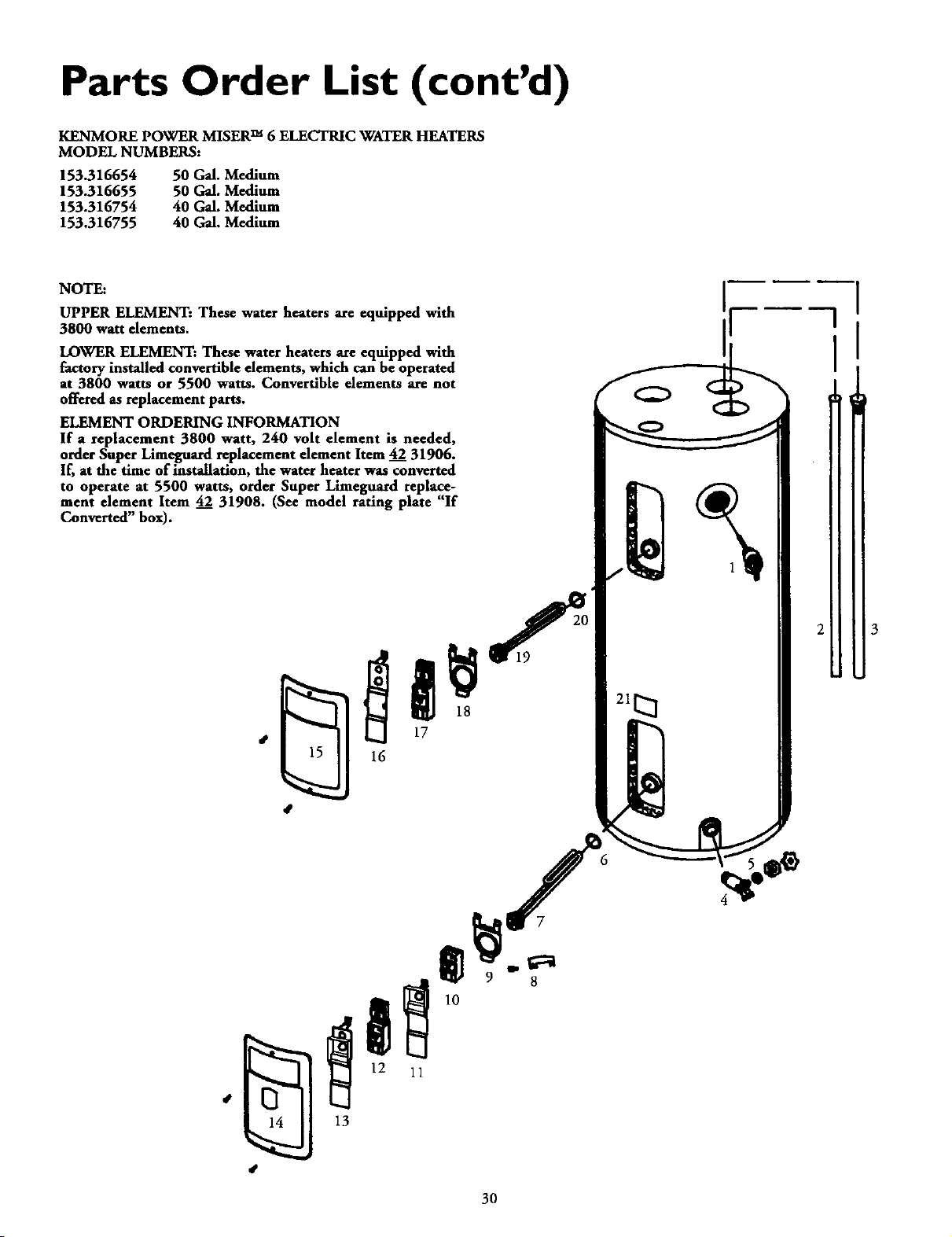
Parts Order List (cont'd)
KENMORE POWER MISER TM 6 ELECTRIC WATER HEATERS
MODEL NUMBERS:
153.316654 50 Gal. Medium
153.316655 50 Gal. Medium
153.316754 40 Gal. Medium
153.316755 40 Gal. Medium
NOTE:
UPPER ELEMENT: These water heaters are equipped with
3800 watt elements.
LOWER ELEMENT: These water heaters are equipped with
factory installed convertible elements, which can be operated
at 3800 watts or 5500 watts. Convertible dements are not
offered as replacement parts.
ELEMENT ORDERING INFORMATION
If a replacement 3800 watt, 240 volt element is needed,
order Super Limeguard replacement element Item 42 31906.
If, at the time of installation, the water heater was converted
to operate at 5500 watts, order Super Limeguard replace-
ment element Item 42 31908. (See model rating plate "If
Converted" box).
16
13
3O
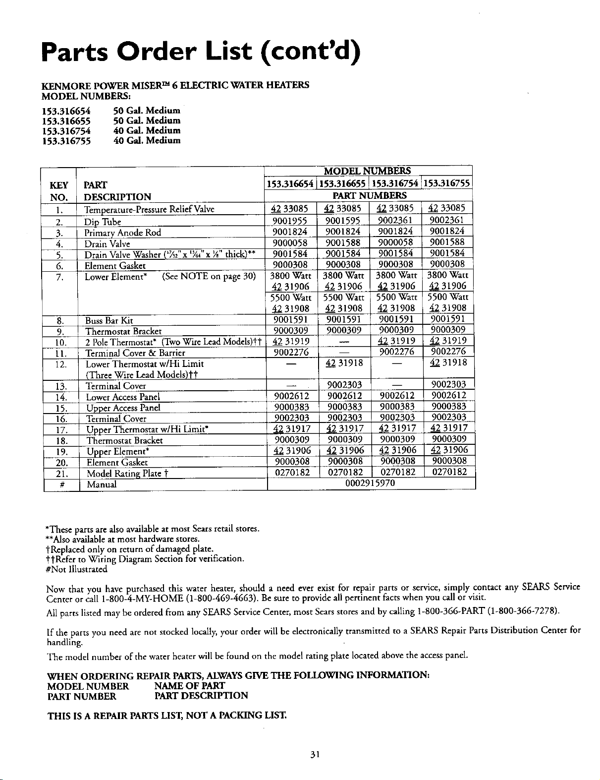
Parts Order List (cont'd)
KENMORE POWER MISER TM 6 ELECTRIC WATER HEATERS
MODEL NUMBERS:
153.316654
153.316655
153.316754
153.316755
50 Gal. Medium
50 Gal. Medium
40 Gal. Medium
40 Gal, Medium
KEY PART
NO. DESCRIPTION
1. Temperature-Pressure Relief Valve
2. Dip Tube
3. Primary Anode Rod
4. Drain Valve
5. Drain Valve Washer (_;' x 'YJ' x V," thick)**
6. Element Gasket
7. Lower Element* (See NOTE on page 30)
8. Buss Bar Kit
9. Thermostat Bracket
10. 2 Pole Thermostat* (Two Wire Lead Models)_l"
11. Terminal Cover & Barrier
12. Lower Thermostat w/Hi Limit
(Three Wire Lead Models)!"'_
13. Terminal Cover
14. Lower Access Panel
15. Upper Access Panel
16. Terminal Cover
17. Upper Thermostat w/Hi Limit*
18. Thermostat Bracket
19. Upper Element*
20. Element Gasket
21. Model Rating Plate t
# Manual
153.316654 153.316755
4233085
9OO1955
9001824
9000058
9001584
9000308
3800Watt
4231906
5500Watt
4231908
9001591
9000309
4231919
9002276
9002612
9000383
9002303
4,231917
9000309
4231906
9000308
0270182
MODEL NUMBERS
153.316655 153.316754
PART NUMBERS
4233085 4233085
9001595 9002361
9001824 9001824
9001588 9000058
9001584 9001584
9000308 9000308
3800Watt 3800Watt
4231906 4231906
5500Watt 5500Watt
4231908 4231908
9001591 9001591
9000309 9000309
-- 4231919
-- 9002276
4231918
9002303
9002612 9002612
9000383 9000383
9002303 9002303
4231917 4231917
9000309 9000309
4231906 4231906
9000308 9000308
0270182 0270182
0002915970
4233O85
9002361
9001824
90O1588
9001584
90003O8
3800Watt
4231906
5500Watt
4231908
9001591
9000309
4231919
9002276
4231918
9002303
9002612
9000383
9002303
4231917
9000309
4231906
9000308
0270182
*These parts are also available at most Sears retail stores.
**Also available at most hardware stores.
tReplaced only on return of damaged plate.
ttRefer to Wiring Diagram Section for verification.
#Not Illustrated
Now that you have purchased this water heater, should a need ever exist for repair parts or service, simply contact any SEARS Service
Center or call 1-800-4-MY-HOME (1-800-469-4663). Be sure to provide all pertinent facts when you call or visit.
All parts listed may be ordered from any SEARS Service Center, most Sears stores and by calling 1-800-366-PART (1-800-366-7278).
If the parts you need are not stocked locally, your order will be electronically transmitted to a SEARS Repair Parts Distribution Center for
handling.
The model number of the water heater will be found on the model rating plate located above the access panel.
WHEN ORDERING REPAIR PARTS, ALWAYSGIVE THE FOLLOWING INFORMATION:
MODEL NUMBER NAME OF PART
PART NUMBER PARTDESCRIPTION
THIS ISA REPAIR PARTSLIST, NOT A PACKING LIST.
31
Warranty
About Your Warranty
THE PRICE OF YOUR WATER HEATER DOES NOT INCLUDE
A FREE CHECKUP SERVICE CALL. On Water Heater Installations
Arranged By Seats, Sears warrants the installation.
ON INSTALLATIONS NOT MADE BY SEARS AUTHORIZED
CONTRACTORS:
1. Your Sears warranty applies to the product only.
2. Sears does not warrant the installation.
3. A charge will be made on service calls due to poor or incomplete
installation. These include:
a. Adjusting thermostat.
b. Leaks in pipes or fittings.
This manual is in non-technical language. It may help you avoid the
cost of a needless service call. Many service calls really aren't needed,
Such aswhen:
1. The electric power is turned "OFF".
2. A water leak isdue to loose pipe or connections.
FULL ONE YEARWARRANTY ON WATER HEATER
For one year from the date of purchase, when your Sears Kenmore water heater is installed and operated in a single-family
residence in accordance with the instructions in this manual, Sears will:
1. Repairdefects in material or workmanship in this water heater, free of charge.
2. Furnish and install a new current model water heater of equal capacity and quality, free of charge, if a leak occurs in the tank.
LIMITEDWARRANTY ON TANKS THAT LEAK
After one year and through 6 years from the date of purchase for water heaters used in a single-family residence, ifa leak occurs in
the tank, Sears will furnish a new current model water heater of equal capacity and quality. Youwill be charged for any
installation.
LIMITED WARRANTY ON PARTS
Aher one year and through 6 years from the date of purchase, when your Sears Kenmore water heater is used in a single-family
residence and is installed and operated in accordancewith the information in this manual, ifa part fails due to a materials or
workmanship, Sears will furnish a replacement free of charge. You will he charged for labor.
If the water heater is subjected to commercial, institutional, industrial or use in residences of two families or more, the above
warranty coverage for tanks that leak is effective for 2 years from the date of purchase and the above parts warranty is effective for I
year from the date of purchase.
To obtain warranty service, SIMPLY CALL 1-800-4MY-HOME (1-800-469-4663). "This warranty applies only while this
product is in use in the United States."
This warranty gives you specific legal rights and you may also have other rights which vary from state to state.
SEARS, ROEBUCK AND CO., Dept. 817 WA, HOFFMAN ESTATES, IL 60179
Sears Installation Warranty
In addition to any warranty extendedto you on the Searsmerchandise
involved,whichwarranty becomeseffectivethe datethe merchandiseis
installed should the workmanship of any Sears arranged installation
prove faulty within one year,Searswill, upon notice trom you, cause
suchfaultsto be correctedat no additionalcost to you. If youwant this
heater professionallyinstalledby Searscontact your SearsSalesperson.
Theywillarrange forprompt, quality installation.
Sears Installation Policy
All installation labor arranged by Sears shall be performed in a neat,
workmanlike manner in accordance with generally accepted trade prac-
tices. Further, all installations shall comply with all locallaws, codes
regulations and ordinances. The customer shall also be protected, dur-
ing installation, by insurance relating to property damage, Worker's
Compensation and Public Liability.
If you want this water heater professionally installed by Sears contact
your Salesperson. They will arrange for prompt, quality installation by
Sears authorized contractors.
Forin-homemajorbrandrepairservice
Call24hoursaday,7daysa week
1-800-4-MY-HOME
(1-800-469-4663)
The model number of yourwaterheater isfound on the modelrating plateon the frontofthewater heater.
Sears r Roebuck and Co. Hoffman Estates IL 60179 U.S.A.
08-99 0002915970-0