Owner's Manual
®
!6.5 HP
ELECTRIC START
42" MOWER
HYDROSTATIO (AUTOMATmC)
LAWN TRACTO
Modet No.
917,271120
• Safety
,, Assembmy
o Operation
,, Maintenance
,, Repair Parts
.4;
CAUTION:
Read and follow alJ
Safety RuJes and hstructions
before operating this equip-
menL
For at_swers to yoL_r questions
about this product, Call:
1°800°659°59t 7
Sears Craftsmatl He_p Line
5 am - 5 prn, Mon ,,Sat
Sears, Roebuck and Coo, Hoffman Estates, IL 60179
Warranty ................................................. 2
Safety Rules ........................................... 2
Assembly ................................................ 8
Operation .............................................. 12
Maintenance Schedule ......................... 19
Maintenance ........................................ .19
Product Specifications ........................... 5
Service and Adjustments ...................... 23
Storage ................................................. 29
Troubleshooting .................................... 30
Repair Parts ......................................... 34
Parts Ordering ....................... Back Cover
LIMITED TWO YEAR WARRANTY ON CRAFTSMAN RIDING EQUIPMENT
For two (2) years from the date of purchase, if this Craftsman Riding Equipment is main-
tained, lubricated and tuned up according to the instructions in the owner's manual,
Sears will repair or replace, free of charge, any parts found to be defective in material or
workmanship.
This Warranty does not cover:
o Expendable items which become worn during normal use, such as blades, spark
plugs, air cleaners, belts, etc.
Tire replacement or repair caused by punctures from outside objects, such as nails,
thorns, stumps, or glass.
• Repairs necessary because of operator abuse, negligence, improper storage or acci-
dent or the failure to maintain the equipment according to the instructions contained in
the owner's manual.
• Riding equipment used for commercial or rental purposes.
LIMITED 90DAY WARRANTY ON BATTERY
For ninety (90) days from date of purchase, if any battery included with this riding equip-
ment proves defective in material or workmanship and our testing determines the bat-
tery will not hold a charge, Sears wilt replace the battery at no charge. In-home warranty
service on your Craftsman riding equipment is available at no charge for 30 days from
the date of purchase. Please contact your nearest service center° After 30 days from the
date of purchase, warranty service is available by taking your Craftsman riding equip-
ment to your nearest Sears Service Center. (in-home warranty service will still be avail-
able after 30 days from the date of purchase but a standard trip charge will apply). This
warranty applies only whimethis product is in the United States. This Warranty gives you
specific legal rights, and you may also have other rights which may vary from state to
state°
Sears, Roebuck and Co., D/817 WA, Hoffman Estates, IL 60179
GENERAL OPERATION
Read, understand, and follow all instruc-
tions in the manual and on the machine
before starting,
o Only allow responsible adults, who are
familiar with the instructions, to operate
the machine.
Clear the area of objects such as rocks,
toys, wire, etc., which could be picked
up and thrown by the blade.
o Be sure the area is clear of other people
before mowing. Stop machine if anyone
enters the area.
o Never carry passengers.
Do not mow in reverse unless absolute-
ly necessary. Always took down and
behind before and while backing,
Be aware of the mower discharge direc-
tion and do not point it at anyone. Do
not operate the mower without either
the entire grass catcher or the guard in
place.
Stow down before turning,
o Never leave a running machine unat-
tended. Always turn off blades, set park-
ing brake, stop engine, and remove
keys before dismounting°
Turnoffbladeswhennotmowing.
. Stopenginebeforeremovinggrass
catcheroruncloggingchute.
Mowonlyindaylightorgoodartificial
light.
* Do not operate the machine while under
the influence of alcohol or drugs.
o Watch for traffic when operating near or
crossing roadways.
. Use extra care when loading or unload-
ing the machine into a trailer or truck.
SLOPE OPERATION
Slopes are a major factor related to loss-
of-control and tipover accidents, which
can result in severe injury or death. All
slopes require extra caution. If you cannot '
back up the slope or if you fee! uneasy on
it, do not mow it.
DO:
= Mow up and down slopes, not across.
Remove obstacles such as rocks, tree
limbs, etc.
Watch for holes, ruts, or bumps, Uneven
terrain could overturn the machine. Tall
grass can hide obstacles.
. Use slow speed. Choose a low gear so
that you will not have to stop or shift
while on the slope.
- Follow the manufacturer's recommen-
dations for wheel weights or counter-
weights to improve stability.
Use extra care with grass catchers or
other attachments. These can change
the stability of the machine.
* Keep all movement on the slopes stow
and gradual. De not make sudden
changes in speed or direction.
Avoid starting or stopping on a slope. If
tires lose traction, disengage the blades
and proceed slowly straight down the
s!ope,
DO NOT:
, Do nottum on slopes unless necessary,
and then, turn slowly and gradually
downhill, if possible.
o Do not mow near drop-offs, ditches, or
embankments. The mower could sud-
denly turn over if a wheel is over the
edge of a cliff or ditch, or if an edge
caves in.
* Do notmow on wet grass.Reduced
tractioncouldcause sliding.
• Do nottry to stabilize the machine by
putting your foot on the ground.
Do not use grass catcher on steep
slopes.
CHILDREN
Tragic accidents can occur if the operator
is not alert to the presence of children.
Children are often attracted to the
machine and the mowing activity. Never
assume that children will remain where
you last saw them.
• Keep children out of the mowing area
and under the watchful care of another
responsible adult.
- Be alert and turn machine off if children
enter the area.
, Before and when backing, look behind
and down for small children.
• Never carry children. They may fall off
and be seriously injured or interfere with
safe machine operation.
• Never allow children to operate the
machine.
o Use extra care when approaching blind
corners, shrubs, trees, or other objects
that may obscure vision.
SERVICE
. Use extra care in handling gasoline and
other fuels. They are flammable and
vapors are explosive.
Use only an approved container.
Never remove gas cap or add fuel
with the engine running. Allow en-
gine to coot before refueling, Do not
smoke.
Never refuel the machine indoors.
Never store the machine or fuel
container inside where there is an
open flame, such as a water heater.
. Never run a machine inside a closed
area.
o Keep nutsand bolts,especiallyblade
attachmentbolts,tightand keep equip-
merit in good condition.
Never tamper with safety devices,
Check their proper operation regularly.
• Keep machine free of grass, leaves, or
other debris build-up. Clean oil or fuel
spillage. Allow machine to cool before
storing,
o Stop and inspect the equipment if you
strike an object. Repair, if necessary,
e
before restarting.
Never make adjustments or repairs with
the engine running.
Grass catcher components are subject
to wear, damage, and deterioration,
which could expose moving parts or
allow objects to be thrown. Frequently
check components and replace with
, Be sure the area is clear of other people
before mowing. Stop machine if anyone
enters the area.
• Never carry passengers.
° Do not mow in reverse unless absolute-
!y necessary. Always bok ,,ore,"_....,a, ,u'_
behind before and while backing.
- Never carry children. They may fall off
and be Seriously injured or interfere with
safe machine operation.
, Keep children out of the mowing area
and under the watchful care of another
responsible adult.
° Be alert and turn machine off if children
enter the area.
. Before and when backing, look behind
and down for smart chitdren.
,_Look for this symbol to point out impor-
tant safety precautions, it means CAU-
TION!!! BECOME AWARE!!! YOUR SAFE-
TY IS INVOLVED.
_CAUTION: in order to prevent acciden-
tal starting when setting up, transporting,
adjusting or making repairs always discon-
nect spark plug wire and place wire where
it cannot contact spark plug.
manufacturer's recommended parts,
when necessary.
Mower blades are sharp and can cut.
Wrap the blade(s) or wear gloves, and
use extra caution when servicing them.
° Check brake operation frequently.
Adjust and service as required.
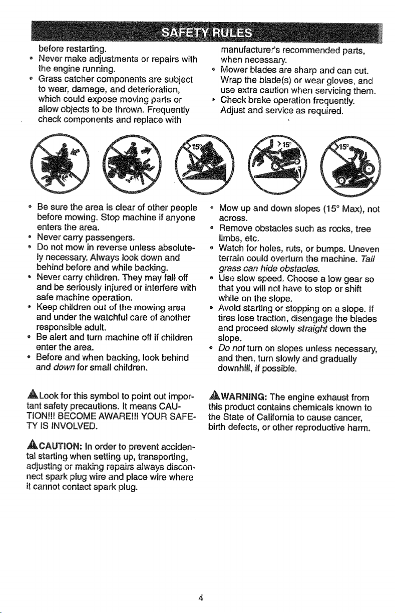
• Mow up and down slopes (15 ° Max), not
across.
- Remove obstacles such as rocks, tree
limbs, etc.
, Watch for holes, ruts, or bumps. Uneven
terrain could overturn the machine. Taft
grass can hide obstacles.
, Use slow speed. Choose a low gear so
that you will not have to stop or shift
while on the slope.
° Avoid starting or stopping on a slope. If
tires lose traction, disengage the blades
and proceed slowly straight down the
slope.
• Do notturn on slopes unless necessary,
and then, turn slowly and gradually
downhill, if possible.
,_WARNING: The engine exhaust from
this product contains chemicals known to
the State of California to cause cancer,
birth defects, or other reproductive harm.

PRODUCT SPECIFICATIONS
GASOLINE 1.25 GALLONS
CAPACITY
AND TYPE: UNLEADED
REGULAR
OiL TYPE SAE 30
(API-SF/SG/SH): (above 32°F)
SAE 10W-30
(below 32°F)
(_IL CAPACITY: W/FILTER: 4.0 PINTS
W/O FILTER: &5 PINTS
SPARK PLUG: Champion RC12YC
(GAP: .040")
GROUND SPEED FORWARD: 0 _4.5
(MPH): REVERSE: 0 - 2.0
TIRE PRESSURE: FRONT: 14 PSi
REAR: 10 PSI
CHARGING
SYSTEM: 15 @ 3600
BATTERY: AMP/HR: 30
MIN. CCA: 280
CASE SIZE: U1R
IB__BOLT 27-35 iT. LBS.
TORQUE:
CONGRATULATIONS on your purchase
of a Craftsman Tractor. It has been
designed,engineeredand manufactured
to giveyouthe best possibledependability
and performance.
Shouldyou experienceany problem you
cannoteasily remedy,please contactyour
nearest Sears Authorized Service Center.
We have competent, well-trained techni-
cians and the proper tools to service or
repair this tractor.
Please read and retain this manual. The
instructions will enable you to assemble
and maintain your tractor properly, Always
observe the "SAFETY RULES".
MAINTENANCE AGREEMENT
ASears MaintenanceAgreement is avail-
able onthis product.Contact yournearest
Searsstore for details.
CUSTOMER RESPONSIBILITIES
= Read and observe the safety rules.
= Follow a regular schedule in maintain-
ing, caring for and using your tractor.
, Foltow the instructions under "Mainte-
nance" and "Storage" sections of this
owner's manual.
_,WARNiNG: This tractor is equipped
with an internal combustion engine and
should not be used on or near any unim-
proved forest-covered, brush-covered or
grass-covered land unless the engine's
exhaust system is equipped with a spark
arrester meeting applicable local or state
laws (if any), If a spark arrester is used, it
should be maintained in effective working
order by the operator.
In the state of California the above is
required by law (Section 4442 of the
California Public Resources Code). Other
states may have similar laws. Federal
laws apply on federal lands. A spark
arrester for the muffler is available through
your nearest Sears Authorized Service
Center (See REPAIR PARTS section of
this manual).
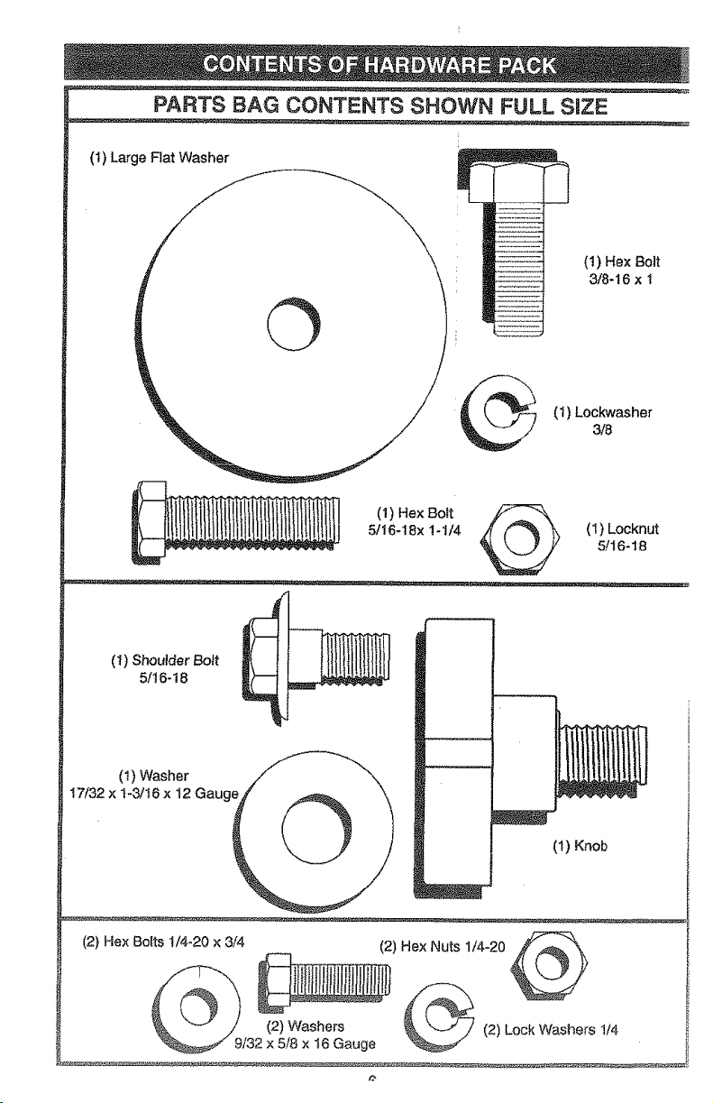
PARTS BAG CONTENTS SHOWN FULL S_ZE
(1) Large Flat Washer
©
(!) Hex BoJt
3/8-16 x 1
(t) Lockwasher3/8
(1) Hex Bolt _-k
5/16qBx 1-1/4 _ (I) Locknut
5/16_18
(t) Shoulder Bott
5/16-18
(t) Washer
17/32 x 1-3/t6 x 12 Gauge
(1) Knob
l
Hex Bolts t/4-20 × __ (2) Hex Nuts 1/4-20 _k
(2) 3/4
_. '-'-" // (2) Washers (2) Lock Washers 114
9/32 x 5/8 x 16 Gauge
D
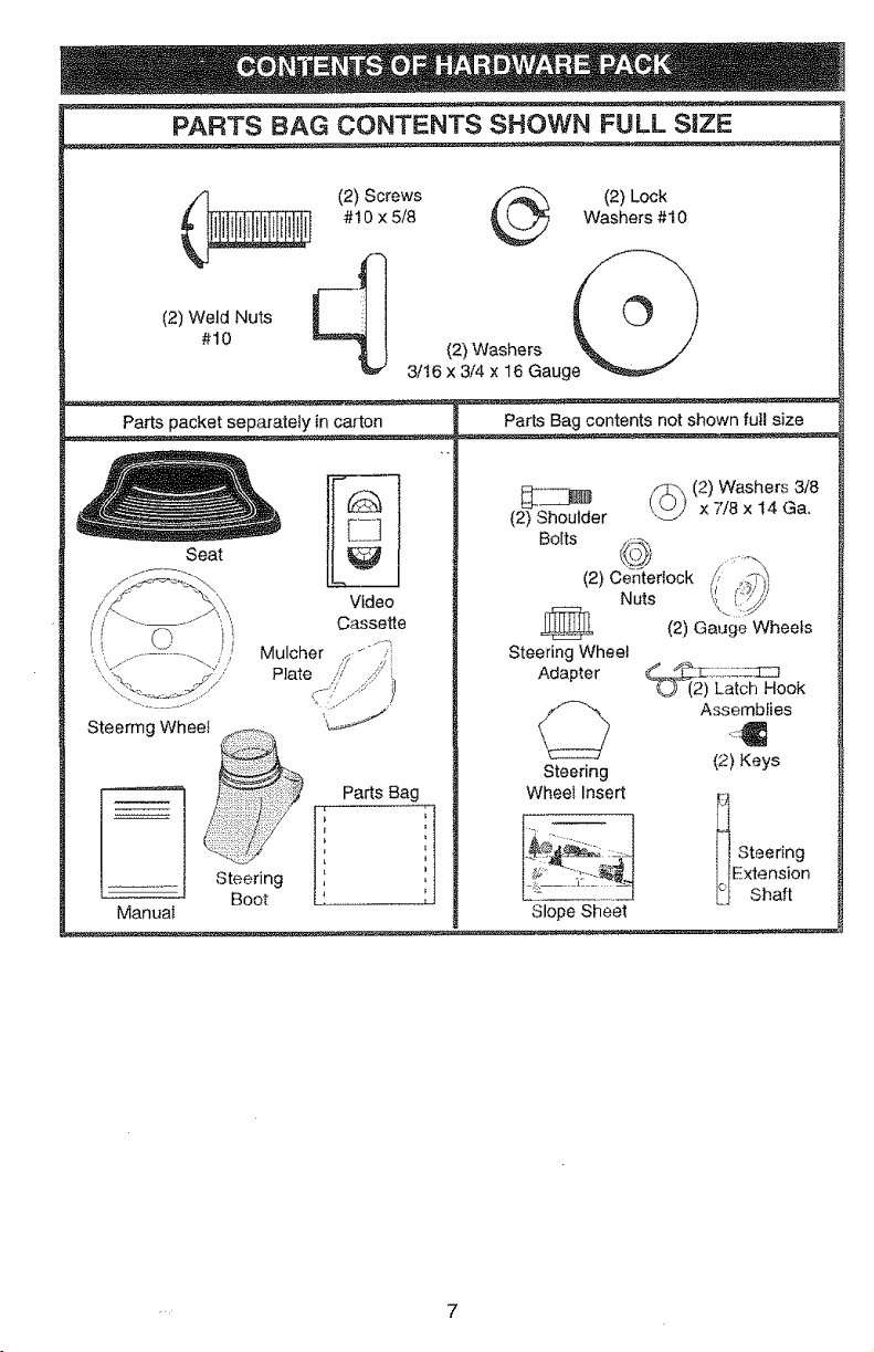
PARTS BAG CONTENTS SHOWN FULL S|ZE
(2) Weld Nuts i---iI !
#t0
(2) Screws _ (2) Lock
#t0 x 5/8 _ Washers #10
3/t 6 (2_i_'taSlh6r_au ge_
Parts packet separately in carton
Seat
Video
Cassette
Mulcher ,j _ ,;:'i
Plate // ,,::"i
SteeringWhee_ _............
I ..... f Steering
' _J Boot
Manua_
Parts Bag contents not shown full size
_Shoulder _ (2) Washers 3/8
(2) x 7/8 x I4 Ga.
Bolts
(2) Centertock (/ ,.q-,"_
Nuts
Steering Wheet
Adapter
Steering
Wheel Insert
....
Slope Sheet
(2) Ga_Jge Wheels
;TC:,'::;;,CCCC_C]
2) Latch Hook
Assemblies
(2) Keys
ili Steering
1FExtension
Et Shaft
Your new tractor has been assembled at the factory with exception of those parts left
unassembled for shipping purposes. To ensure safe and proper operation of your tracto
all parts and hardware you assemble must be tightened securely. Use the correct tools
as necessary to insure proper tightness. Review the video cassette before you begin.
TOOLS REQUIRED FOR
ASSEMBLY
A socket wrench set wi!l make assembly
easier. Standard wrench sizes you need
are fsted below.
(1) 9/16" wrench (1) 3/4" Socket w/
(2) 7f16" wrenches drive t'achet
(2) I/2" wrench (1) Phillips Screw-
(1) Utiity knife driver
(1)Piers (1) Tire pressure
gauge
When right or left hand is mentioned in
this manual, it means, from your point of
view, when you are in the operating posio
lion (seated behind the steering wheel).
TO REMOVE TRACTOR FROM
CARTON
UNPACK CARTON
, Remove all accessible loose parts and
parts boxes from shipping carton (See
page 6).
Cut, from top to bottom, along lines on
all four corners of shipping carton, and
lay panels flat.
- Remove mower and package materials.
* Check for any additional loose parts or
boxes and remove.
BEFORE ROLLING TRACTOR OFF
SKiD
ATTACHSTEERING WHEEL
ASSEMBLE EXTENSION SHAFT AND
BOOT
Slide extension shaft onto lower steer-
ing shaft. Align mounting holes in exten-
sion and lower shafts and install 5/16
hex bot and tocknut. Tighten securely.
IMPORTANT: Tighten bolt and nut secure-
ty to !8-22 ft. Ibs. torque.
Place tabs of steering boot over tab
slots in dash and push down to secure.
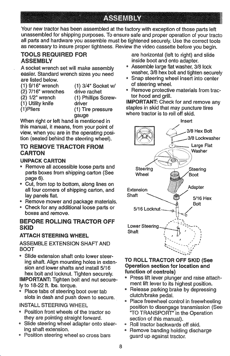
iNSTALL STEER1NG WHEEL
o Position front wheels of the tractor so
they are pointing straight forward.
- Slide steering wheel adapter onto steer-
ing shaft extension.
o Position steering wheel so cross bars
are horizontal (_eft to right) and slide
inside boot and onto adapter.
Assemble large lat washer, 3/8 lock
washer, 3/8 hex bolt and tighten securely
, Snap steering whee! insert into center
of steering wheel
o Remove protective materials from trac-
tor hood and grill.
iMPORTANT: Check for and remove any
staples in skid that may puncture tires
where tractor is to rol off skid.
Insert
z_Gi i_::::. \ Washer
:J
Steering ..... L_ Steering
Wheel _ _Boot
Extension _ /dapter
Shaft _._ 5/16 Hex
! Bolt
5!t6 Locknut--_-...._ _ /
Lower Steering_ / ,;_"_ .... .
Shaft , ,,
TO ROLL TRACTOR OFF SKID (See
Operation section for tocafon and
function of controls)
o Press lift lever plunger and raise attach-
ment lift lever to its highest position.
- Release parking brake by depressing
clutch/brake pedal.
* Place freewheel contre_ in freewheeling
position to disengage transmission (See
"TO TRANSPORT" in the Operation
section of this manual).
- Roll tractor backwards off skid.
, Remove banding holding discharge
guard up against tractor.
HOW TO SET UP YOUR TRACTOR
CONNECT BATTERY
_,CAUTION: Do not short battery termi-
nals by allowing a wrench or any other
object to contact both terminals at the
same time. Before connecting battery, re-
move metat bracelets, wristwatch bands,
rings, etc. Positive terminal must be con-
nected first to prevent sparking from acci-
dental grounding.
= Remove cardboard packing from seat
pan and lift seat pan to raised position.
, Open battery box door and remove pro-
tective plastic.
- Remove terminal protective caps and
discard.
- If this battery is put into service after
month and year indicated on label (label
located between terminals) charge bat-
tery for minimum of one hour at 6-I0
amps.
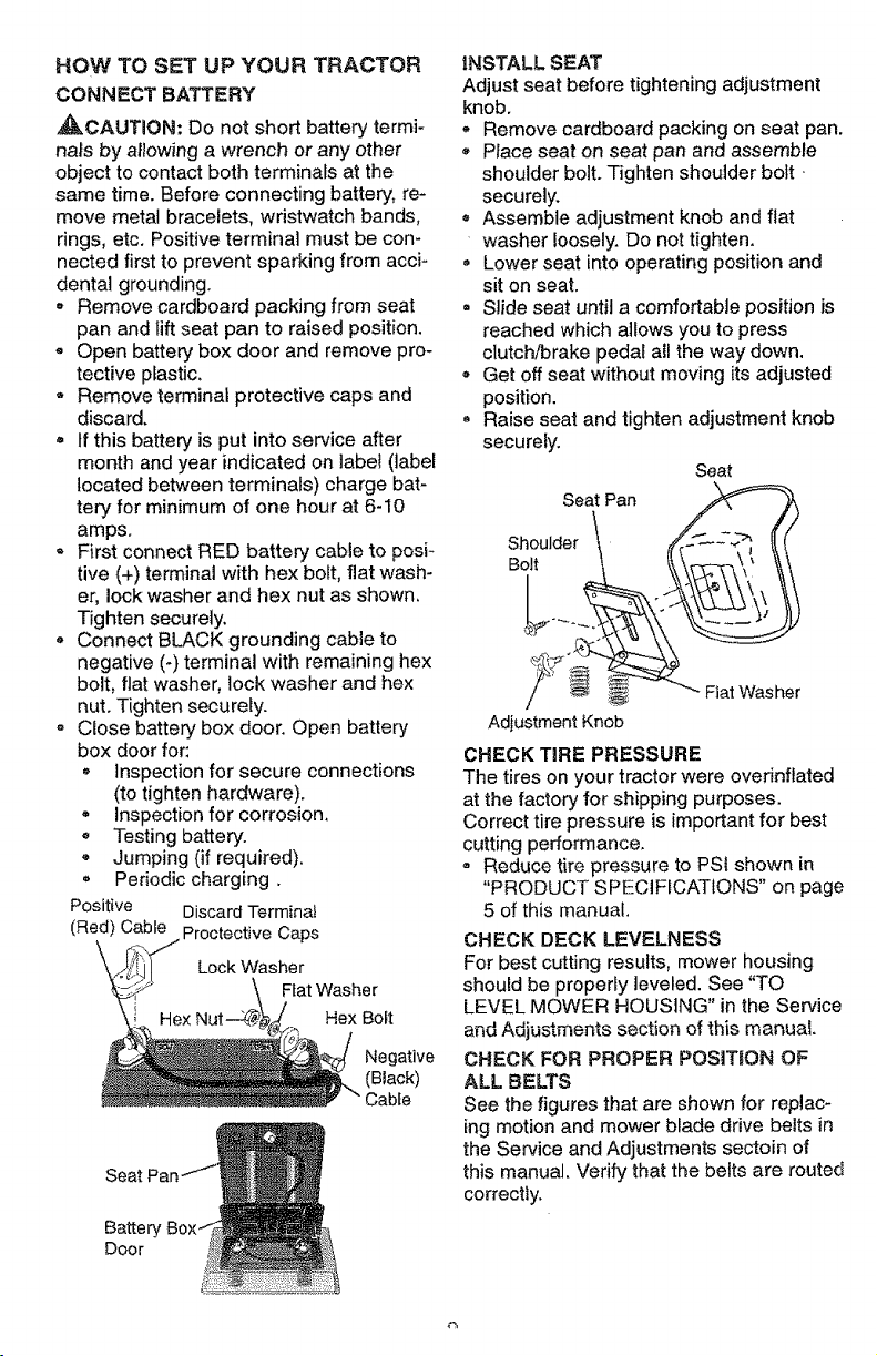
- First connect RED battery cable to posi-
tive (+) terminal with hex bolt, flat wash-
er, lock washer and hex nut as shown,
Tighten securely.
• Connect BLACK grounding cable to
negative (-) terminal with remaining hex
bolt, flat washer, lock washer and hex
nut. Tighten securely.
Close battery box door. Open battery
box door for:
= inspection for secure connections
(to tighten hardware).
= inspection for corrosion,
• Testing battery.
- Jumping (if required).
, Periodic charging.
Positive Discard Terminal
(Red) Cable Proctective Caps
Lock Washer
Ftat Washer
Hex Hex Bolt
Negative
(Black)
Battery
Door
iNSTALL SEAT
Adjust seat before tightening adjustment
knob.
* Remove cardboard packing on seat pan.
Place seat on seat pan and assemble
shoulder bolt. Tighten shoulder bolt
securely.
, Assembte adjustment knob and flat
washer loosely. Do not tighten.
Lower seat into operating position and
sit on seat.
= Slide seat until a comfortable position is
reached which allows you to press
clutch/brake pedal all the way down.
o Get off seat without moving its adjusted
position.
Raise seat and tighten adjustment knob
securely.
Seat
Seat Pan
ShouI]er ".
Adiustment Knob
CHECK TiRE PRESSURE
The tires on your tractor were ovednflated
at the factory for shipping purposes.
Correct tire pressure is important for best
cutting performance.
= Reduce tire pressure to PSi shown in
"PRODUCT SPECIFICATIONS" on page
5 of this manual.
CHECK DECK LEVELNESS
For best cutting results, mower housing
should be properly leveled. See "TO
LEVEL MOWER HOUSING" in the Service
and Adjustments section of this manual.
CHECK FOR PROPER POSIT_ON OF
ALL BELTS
See the figures that are shown for replac-
ing motion and mower blade drive belts in
the Service and Adjustments sectoin of
this manual. Verify that the belts are routed
correctly.
CHECK BRAKE SYSTEM
After you learn how to operate your trac-
tor, check to see that the brake is properly
adjusted. See "TO ADJUST BRAKE" in
the Service and Adjustments section of
this manual
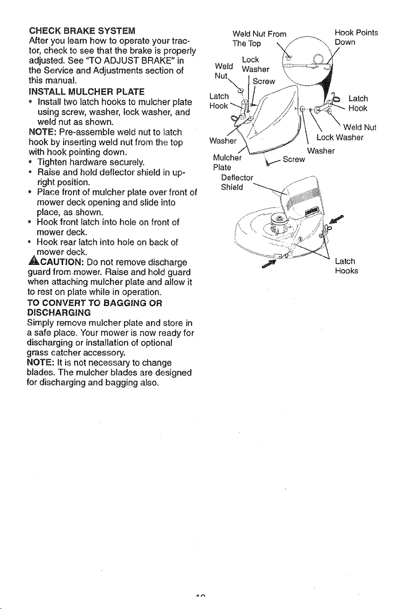
INSTALL MULCHER PLATE
• Install two latch hooks to mutcher plate
using screw, washer, lock washer, and
weld nut as shown.
NOTE: Pre-assemble weld nut to latch
hook by inserting weld nut from the top
with hook pointing down.
• Tighten hardware securely.
, Raise and hold deflector shield in up-
right position.
= Place front of muicher plate over front of
mower deck opening and slide into
place, as shown.
Hook front latch into hole on front of
mower deck.
, Hook rear latch into hole on back of
mower deck.
_CAUTION: Do not remove discharge
guard from,mower. Raise and hold guard
when attaching mulcher plate and allow it
to rest on plate while in operation.
TO CONVERT TO BAGGING OR
DISCHARGING
Simply remove mulcher plate and store in
a safe place. Your mower is now ready for
discharging or installation of optional
grass catcher accessory.
NOTE: It is not necessary to change
blades. The mulcher blades are designed
for discharging and bagging also.
Weld Nut From
The Top
Lock
Wetd Washer
Nut
Latch
Washer
Mulcher
Plate
Deflector
Shield
"_1-- Screw
Hook Points
Down
Latch
Hook
Weld Nut
Lock Washer
Wash er
Latch
Hooks
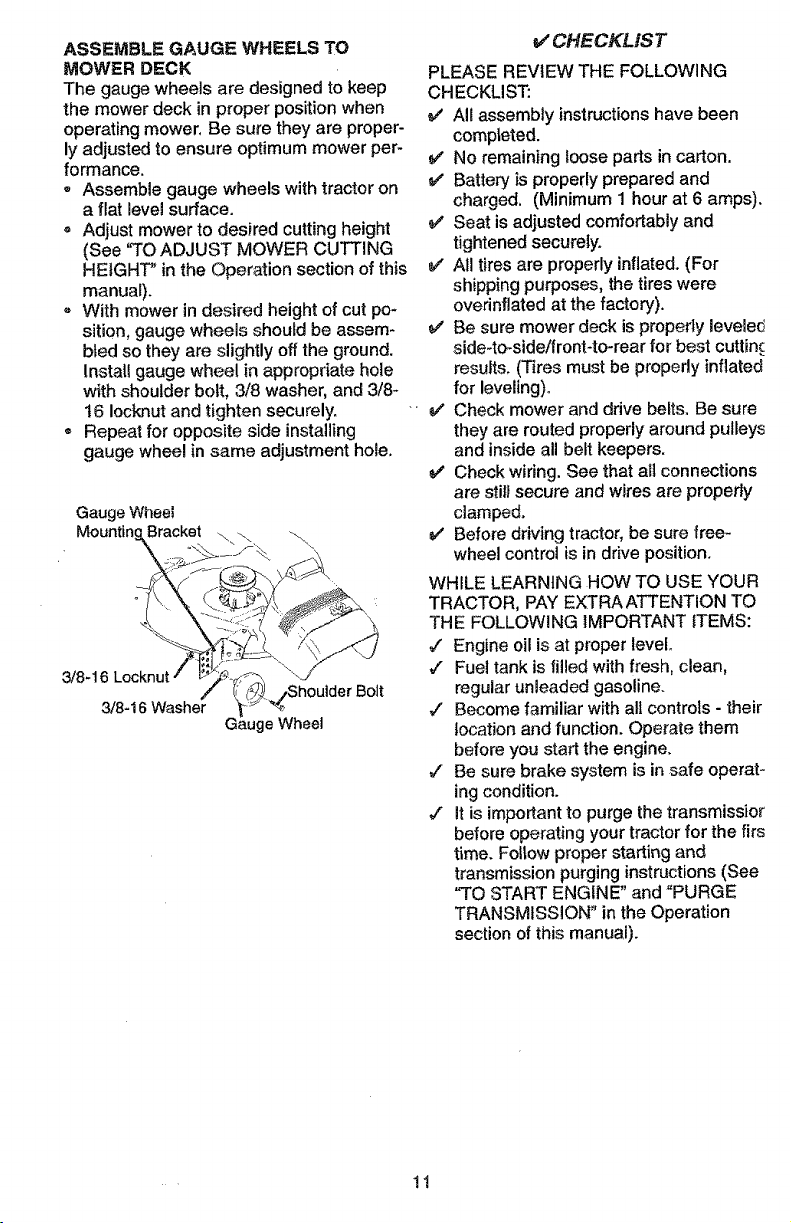
ASSEMBLE GAUGE WHEELS TO
MOWER DECK
The gauge wheels are designed to keep
the mower deck in proper position when
operating mower, Be sure they are proper-
ly adjusted to ensure optimum mower per-
formance.
- Assemble gauge wheels with tractor on
a flat level surface.
- Adjust mower to desired cutting height
(See "TO ADJUST MOWER CUTTING
HEIGHT" in the Operation section of this
manual).
With mower in desired height of cut po-
sition, gauge wheels shoutd be assem-
bled so they are slightly off the ground.
Install gauge wheel in appropriate hole
with shoulder bolt, 3/8 washer, and 3/8-
16 Iocknut and tighten securely.
= Repeat for opposite side installing
gauge wheel in same adjustment hole,
Gauge Wheel
Mountin Bracket _
3/8-16
)ulder Bolt
3/8-16 Washer
Wheel
v' CHECKLIST
PLEASE REVIEW THE FOLLOWING
CHECKLIST:
All assembly instructions have been
completed.
V' No remaining loose parts in carton.
Battery is properly prepared and
charged, (Minimum 1 hour at 6 amps).
Seat is adjusted comfortably and
tightened securely.
J All tires are properly inflated. (For
shipping purposes, the tires were
ovednflated at the factory).
v' Be sure mower deck is propedy leveled
side-to-side!front4o-rear for best cuttin£
results. (Tires must be properly inflated
for leveling)_
Check mower and drive belts. Be sure
they are routed properly around pulleys
and inside all belt keepers.
v" Check wiring. See that all connections
are still secure and wires are properly
clamped.
v' Before driving tractor, be sure free-
wheel control is in drive position.
" V"
WHILE LEARNING HOW TO USE YOUR
TRACTOR, PAY EXTRA ATTENTION TO
THE FOLLOWING IMPORTANT ITEMS:
#" Engine oil is at proper level.
#" Fuel tank is filled with fresh, clean,
regular unleaded gasoline.
#" Become familiar with all controls - their
location and function. Operate them
before you start the engine.
,/ Be sure brake system is in safe operat-
ing condition.
•/ it is important to purge the transmissior
before operating your tractor for the firs
time. Follow proper starting and
transmission purging instructions (See
"TO START ENGINE" and =PURGE
TRANSMISSION" in the Operation
section of this manual).
tl
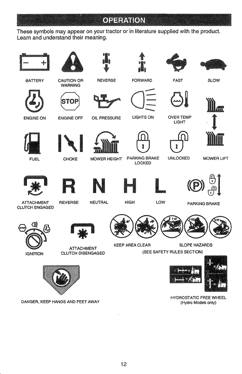
Thesesymbolsmayappearonyourtractoror in literature suppled with the product.
Learn and understand their meaning.
E::3A
BATTERY CAUTION OR
WARNING
ENGINE ON ENG{NE OFF
FUEL
I\1
CHOKE
REVERSE
OIL PRESSURE
MOWER HEIGHT
FORWARD FAST
QI
MGHTS ON OVER TEMP
LIGHT
0
PARKING BRAKE
LOCKED
SLOW
UNLOCKED MOWER LIFT
ATTACHMENT
CLUTCH ENGAGED
IGNITION
REVERSE NEUTRAL
HIGH
L c®)_l
LOW PARKING BRAKE
r_
ATTACHMENT
CLUTCH DISENGAGED
KEEP AREA CLEAR SLOPE HAZARDS
(SEE SAFETY RULES SECTION)
DANGER, KEEP HANDS AND FEET AWAY
HYDROSTATIC FREE WHEEL
(Hydro Models only)
t2
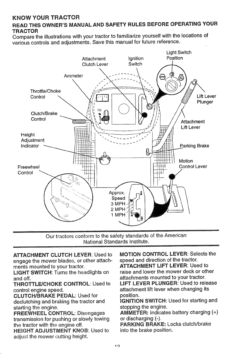
KNOWYOUR TRACTOR
READ THIS OWNER'S MANUAL AND SAFETY RULES BEFORE OPERATING YOUR
TRACTOR
Compare the illustrations with your tractor to familiarize yourself with the locations of
various controls and adjustments. Save this manual for future reference.
Attachment ignition
Clutch Lever Switch
Light Switch
Position
Ammeter
Throttle/Choke
Control
Clutch/Brake
Control
Height
Adjustment
Indicator
Lift Lever
Plunger
Attachment
Lift Lever
Brake
Freewheel
Control
Motion
Control Lever
Our tractors conform to the safety standards of the American
National Standards institute.
ATTACHMENT CLUTCH LEVER: Used to
engage the mower blades, or other attach-
ments mounted to your tractor.
LIGHT SWITCH: Turns the headlights on
and off.
THROTTLE/CHOKE CONTROL: Used to
control engine speed.
CLUTCH/BRAKE PEDAL: Used for
declutching and braking the tractor and
starting the engine,
FREEWHEEL CONTROL: Disengages
transmission for pushing or slowly towing
the tractor with the engine off.
HEIGHT ADJUSTMENT KNOB: Used to
adjust the mower cutting height,
MOTION CONTROL LEVER: Selects the
speed and direction of the tractor.
ATTACHMENT LIFT LEVER: Used to
raise and lower the mower deck or other
attachments mounted to your tractor.
LIFT LEVER PLUNGER: Used to release
attachment lift lever when changing its
position.
_GNIT|ON SWITCH: Used for starting and
stopping the engine,
AMMETER: indicates battery charging (+)
or discharging (-).
PARKING BRAKE: Locks clutch/brake
into the brake position.
-1o
The operation of any tractor can result in foreign objects thrown into the
eyes, which can result in severe eye damage. Always wear safety glasses
or eye shields whime operating your tractor or performing any adjustments e_
repairs. We recommend a wide vision safety mask over the spectacles, or
standard safety glasses.
HOW 3"0 USE YOUR TRACTOR
"Yourtractor is equipped with an operator
presence sensing switch. When engine is
running, any attempt by the operator to
leave the seat without first setting the
parking brake will shut off the engine.
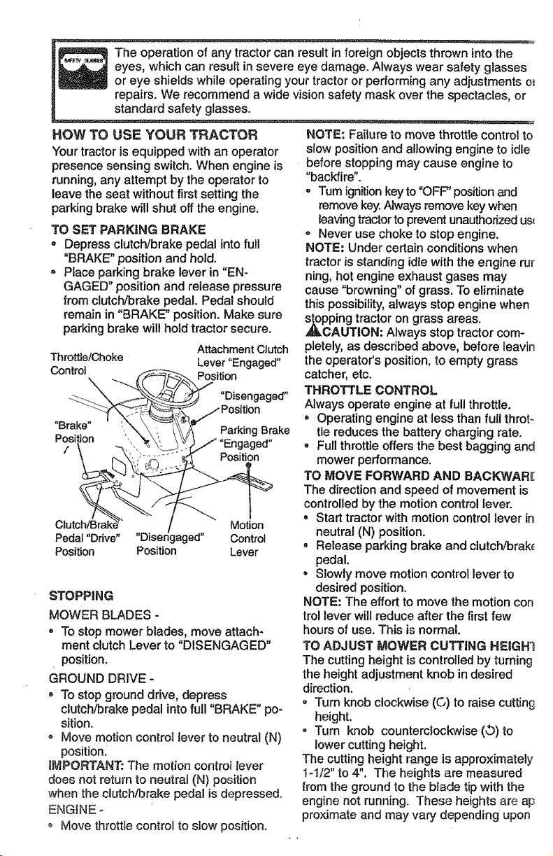
TO SET PARKING BRAKE
= Depress clutch/brake pedal into full
"BRAKE" position and hold.
Place parking brake lever in "EN-
GAGED" position and release pressure
from clutch/brake peda!. Pedal should
remain in "BRAKE" position. Make sure
parking brake will hold tractor secure.
Attachment Clutch
Throttle/Choke Lever "Engaged"
Control
_ _--_> Position
----- _ -'__ _ "Disengaged"
/Position
• Par.,o0Bra.e
..... /"En agod"
r.. \,_.,'-- _ _- Position
Pedal "Drive" ' Disengaged" Control
Position Position Lever
STOPPING
MOWER BLADES -
= To stop mower biades, move attach-
ment clutch Lever to "DISENGAGED"
position.
GROUND DRIVE-
® To stop ground drive, depress
clutch/brake pedal into full "BRAKE" po-
sition.
• Move motion control lever to neutral (N)
position.
iMPORTANT: The motion controt lever
does not return to neutrat (N) position
when the clutch!brake pedal is depressed.
ENGINE
o Move throttle contro_ to slow position.
NOTE; Failure to move throttle control to
slow position and allowing engine to idle
before stopping may cause engine to
"backfire".
• Turn ignition key to "OFF" position and
remove key. Always remove key when
Leavingtractor to prevent unauthorized us_
• Never use choke to stop engine.
NOTE: Under certain conditions when
tractor is standing idle with the engine fur
ning, hot engine exhaust gases may
cause "browning" of grass. To eliminate
this possibility, always stop engine when
pping tractor on grass areas.
CAUTION: Always stop tractor com-
pletely, as described above, before teavin
the operator's position, to empty grass
catcher, etc.
THROTTLE CONTROL
Always operate engine at full throttle.
, Operating engine at tess than full throto
tie reduces the battery charging rate.
o Furl throttle offers the best bagging and
mower performance.
TO MOVE FORWARD AND BACKWARE
The direction and speed of movement is
controlled by the motion control lever.
= Start tractor with motion control lever in
neutral (N) position.
Release parking brake and clutch/brak_
pedal.
o Slowly move motion control lever to
desired position.
NOTE: The effort to move the motion con
trol lever wilt reduce after the first few
hours of use. This is normal.
TO ADJUST MOWER CUTTING HEIGH1
The cutting height is controlled by turning
the height adjustment knob in desired
direction.
o "rum knob clockwise (G) to raise cutting
height.
, Turn knob counterclockwise (O) to
lower cutting height.
The cutting height range is approximately
1-1/2" to 4". The heights are measured
from the ground to the blade tip with the
engine not running. These heights are ap
proximate and may vary depending upon
soilconditions,heightofgrassandtypes
ofgrassbeingmowed,
Theaveragelawnshouldbecutto
approximately2-1/2inchesduringthe
coolseasonandtoover3inchesduring
hotmonths.Forhealthierandbetter
lookinglawns,mowoftenandafter
moderategrowth,
• For best cutting performance, grass
over 6 inches in height should be
mowed twice. Make the first cut rela-
tively high; the second to desired height.
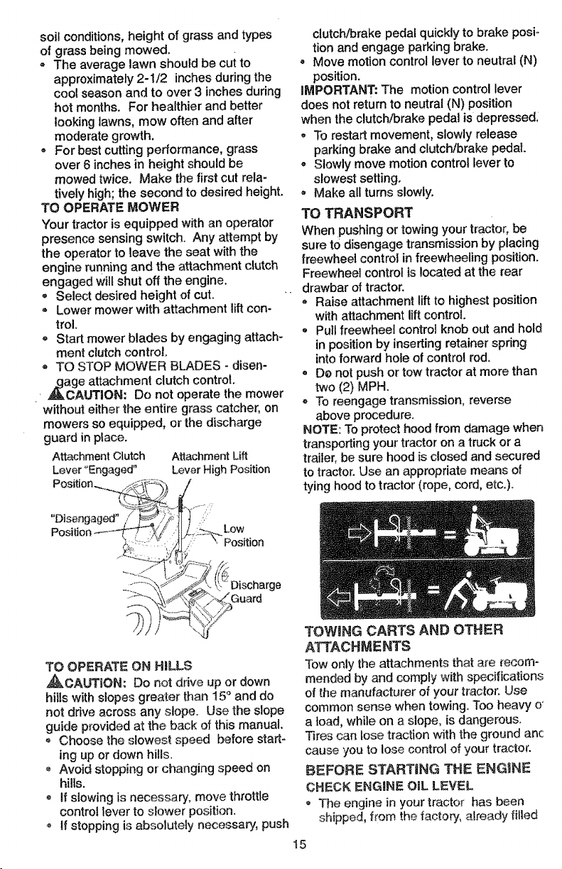
TO OPERATE MOWER
Your tractor is equipped with an operator
presence sensing switch. Any attempt by
the operator to leave the seat with the
engine running and the attachment clutch
engaged wilf shut off the engine.
• Select desired height of cut.
® Lower mower with attachment _iftcon-
trol.
= Start mower blades by engaging attach-
ment dutch control.
= TO STOP MOWER BLADES - disen-
,,gage attachment clutch control.
_L, CAUTtON: Do not operate the mower
without either the entire grass catcher, on
mowers so equipped, or the discharge
guard in place.
Attachment Clutch Attachment Lift
Lever "Engaged" Lever High PosiSon
"Disengaged"
Low
Position
'ge
Guard
TO OPERATE ON HILLS
_CAUTtON: Do not drive up or down
hills with slopes greater than 15° and do
not drive across any slope, Use the slope
guide provided at the back of this manual,
G Choose the slowest speed before start-
ing up or down hills.
Avoid stopping or changing speed on
hills.
o if slowing is necessary, move throttle
control lever to slower position.
if stepping is absolutely necessary, push
clutch/brake pedal quickly to brake posto
tion and engage parking brake.
- Move motion control lever to neutral (N)
position.
iMPORTANT: The motion control lever
does not return to neutral (N) position
when the clutch/brake pedal is depressed.
- To restart movement, slowly release
parking brake and clutch/brake pedal.
o Slowly move motion control lever to
slowest setting.
- Make all turns slowly.
TO TRANSPORT
When pushing or towing your tractor, be
sure tO disengage transmission by placing
freewheel control in freewheeling position.
Freewheel control is located at the rear
drawbar of tractor.
* Raise attachment lift to highest position
with attachment lift control.
o Pull freewheel control knob out and hold
in position by inserting retainer spdng
into forward hote of control rod.
o De not push or tow tractor at more than
two (2) MPH.
To reengage transmission, reverse
above procedure.
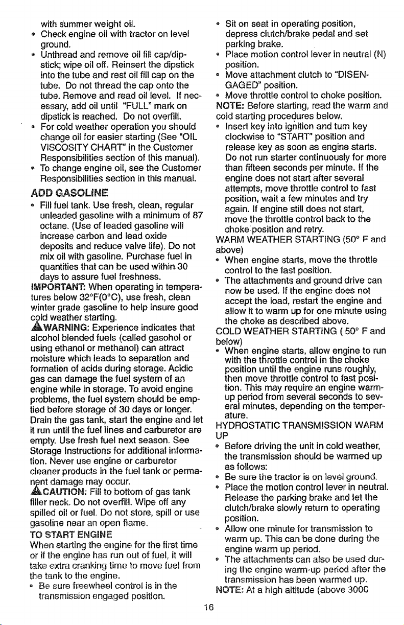
NOTE: To protect hood from damage when
transporting your tractor on a truck or a
trailer, be sure hood is closed and secured
to tractor. Use an appropriate means of
tying hood to tractor (rope, cord, etc.).
TOWING CARTS AND OTHER
ATTACHMENTS
Tow only the attachments that are recom-
mended by and comply with specifications
of the manufacturer of your _actor. Use
common sense when towing. Too heavy o'
a toad, while on a slope, is dangerous.
Tires can lose traction with the ground ant
cause you to lose control of your tractor.
BEFORE STARTING THE ENGINE
CHECK ENGINE OIL LEVEL
]'he engine in your tractor has been
shipped, from the tactoPy, already filled
t5
withSummerweightoit.
Checkengineoilwithtractoron level
ground.
Unthread and remove oil fill cap/dip-
stick; wipe oil off. Reinsert the dipstick
into the tube and rest oil fill cap on the
tube. Do not thread the cap onto the
tube. Remove and read oi_ level. If nec-
essary, add oil until "FULL" mark on
dipstick is reached. Do not overfill.
For cold weather operation you should
change oil for easier starting (See "OIL
VISCOSITY CHART" in the Customer
Responsibilities section of this manual).
® To change engine oil, see the Customer
Responsibilities section in this manual.
ADD GASOLINE
Fill fuel tank. Use fresh, clean, regular
unleaded gasoline with a minimum of 87
octane. (Use of leaded gasoline will
increase carbon and lead oxide
deposits and reduce valve life). Do not
mix oil with gasoline. Purchase fuel in
quantities that can be used within 30
days to assure fuel freshness.
IMPORTANT." When operating in tempera-
tures below 32°F(0°C), use fresh, clean
winter grade gasoline to help insure good
d weather starting,
WARNING: Experience indicates that
alcohol blended fuels (called gasohol or
using ethanol or methanol) can attract
moisture which leads to separation and
formation of acids during storage. Acidic
gas can damage the fuel system of an
engine while in storage. To avoid engine
problems, the fuel system should be emp-
tied before storage of 30 days or longer.
Drain the gas tank, start the engine and let
it run until the fuel lines and carburetor are
empty. Use fresh fuel next season. See
Storage Instructions for additional informa-
tion. Never use engine or carburetor
cleaner products in the fuel tank or perma-
nt damage may occur.
CAUTION: Fill to bottom of gas tank
filler neck. Do not overfill. Wipe off any
spilled oil or fuel. Do not store, spill or use
gasoline near an open flame.
TO START ENGINE
When starting the engine for the first time
or if the engine has run out of fuel, it will
take extra cranking time to move fuel from
the tank to the engine.
- Be sure freewheel control is in the
transmission engaged position.
18
* Sit on seat in operating position,
depress clutch!brake pedal and set
parking brake.
* Place motion control lever in neutral (N)
position.
= Move attachment clutch to "DISEN-
GAG ED" position.
Move throttle control to choke position.
NOTE: Before starting, read the warm and
cold starting procedures below,
® Insert key into ignition and turn key
clockwise to "START" position and
release key as soon as engine starts.
Do not run starter continuously for more
than fifteen seconds per minute, tf the
engine does not start after several
attempts, move throttle control to fast
position, wait a few minutes and try
again, tf engine still does not start,
move the throttle control back to the
choke position and retry.
WARM WEATHER STARTING (50° F and
above)
, When engine starts, move the throttle
control to the fast position.
o The attachments and ground drive can
now be used. If the engine does not
accept the load, restart the engine and
allow it to warm up for one minute using
the choke as described above.
COLD WEATHER STARTING ( 50 ° F and
below)
0 When engine starts, allow engine to run
with the throttle control in the choke
position until the engine runs roughly,
then move throttle control to fast posi-
tion. This may require an engine warm-
up period from several seconds to sev-
eral minutes, depending on the temper-
ature.
HYDROSTATIC TRANSMISSION WARM
UP
* Before driving the unit in cold weather,
the transmission should be warmed up
as follows:
Be sure the tractor is on level ground.
- Place the motion control lever in neutral.
Release the parking brake and let the
clutch/brake slowly return to operating
position.
= Allow one minute for transmission to
warm up. This can be done during the
engine warm up period.
o The attachments can also be used dur-
ing the engine warm-up period after the
transmission has been warmed up.
NOTE: At a high altitude (above 3000
feet)orin cold temperatures (below 32 F)
the carburetor fuel mixture may need to be
adjusted for best engine performance.
See "TO ADJUST CARBURETOR" in the
Service and Adjustments section of this
manual.
,_RGE TRANSMISSION
CAUTION: Never engage or disen-
gage freewheel lever while the engine is
running.
To ensure proper operation and perfor-
mance, it is recommended that the trans-
mission be purged before operating tractor
for the first time. This procedure will
remove any trapped air inside the trans-
mission which may have developed during
shipping of your tractor_
IMPORTANT: Should your transmission
require removal for service or replace-
ment, it should be purged after reinstalta-
tion before operating the tractor.
- Place tractor safely on level surface with
engine off and parking brake set.
Disengage transmission by placing free-
wheel control in freewheeling position
(See %0 TRANSPORT' in this section
of manual).
Sitting in the tractor seat, start engine.
After the engine is running, move throt-
tle control to slow position. With motion
control lever in neutral (N) position,
slowly disengage clutch!brake pedal.
= Move motion control lever to full forward
position and hold for five (5) seconds.
Move lever to full reverse position and
hold for five (5) seconds. Repeat this
procedure three (3) times.
NOTE: During this procedure there will be
no movement of drive wheels. The air is
being removed from hydraulic drive sys-
tem.
- Move motion control lever to neutral (N)
position. Shut off engine and set parking
brake.
• Engage transmission by placing free-
wheel control in driving position (See
"TO TRANSPORT" in this section of
manual).
Sitting in the tractor seat, start engine.
After the engine is running, move throt-
tle control to half (1/2) speed. With
motion control iever in neutral (N) posi-
tion, stowly disengage clutch!brake
pedal.
• Slowly move motion control lever for-
ward; after the tractor moves approxi-
mately five (5) feet, slowly move motion
control lever to reverse position. After
the tractor moves approximately five (5)
feet return the motion control lever to
the neutral (N) position. Repeat this pro-
cedure with the motion control lever
three (3) times.
= Your tractor is now purged and ready for
normal operation.
MOWING TIPS
= Tire chains cannot be used when the
mower housing is attached to tractor.
o Mower should be properly leveled for
best mowing performance. See %0
LEVEL MOWER HOUSING" in the
Service and Adjustments section of this
manual.
• The left hand side of mower should be
used for trimming.
, Drive so that clippings are discharged
onto the area that has been cut. Have
the cut area to the right of the tractor.
This will result in a more even distribu-
tion of clippings and more uniform cut-
ting.
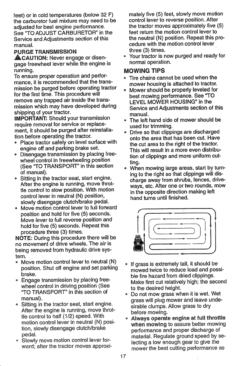
When mowing large areas, start by turn-
ing to the right so that clippings wilt dis-
charge away from shrubs, fences, drive-
ways, etc. After one or two rounds, mow
in the opposite direction making left
hand turns until finished.
I7
® If grass is extremely tall, it should be
mowed twice to reduce load and possi-
ble fire hazard from dried clippings.
Make first cut relatively high; the second
to the desired height.
• Do not mow grass when it is wet. Wet
grass will plug mower and leave unde-
sirable clumps. Allow grass to dr,i
before mowing.
- Always operate engine at fu|! throttle
when mewing to assure better mowing
performance and proper discharge of
materia!. Regulate ground speed by se-
lecting a tow enough gear to give the
mower the best cutting performance as
andgivebestperformanceoftheat-
tachmentbeingused.
MULCHING MOWING TiPS
iMPORTANT: For best performance, keep
mower housing free of built-up grass and
trash. Ctean after each use.
- The special mulching blade will recut
the grass clippings many times and
reduce them in size so that as they fail
onto the lawn they will disperse into the
grass and not be noticed. Also, the
mulched grass will biodegrade quickly
to provide nutrients for the lawn. Always
mulch with your highest engine (blade)
speed as this will provide the best recut-
ting action of the blades.
• Avoid cutting your lawn when it is wet.
Wet grass tends to form clumps and
interferes with the mulching action. The
best time to mow your lawn is the early
afternoon. At this time the grass has
dried and the newly cut area wilt not be
exposed to the direct sun.
..... E......
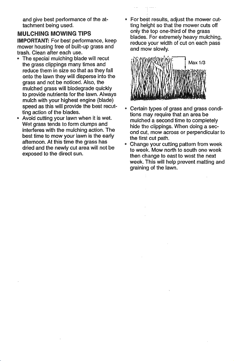
For best results, adjust the mower cut-
ting he!ght so that the mower cuts off
only the top one-third of the grass
blades i For extremely heavy mulching,
reduce your width of cut on each pass
and mow slowly.
Max t/3
, Certain types of grass and grass condi-
tions may require that an area be
mulched a second time to completely
hide the clippings. When doing a sec-
ond cut, mow across or perpendicular to
the first cut path.
Change your cutting pattern from week
to week. Mow north to south one week
then change to east to west the next
week. This will help prevent matting and
grainir_g of the lawn.
CUSTOMER RESPONSiBILITiES
a - # eqUip_3_ With oil _ilter, change oil every 50 bouts.
4 - _ep_ac_ b_ad_s mo_ts- often when mow_ _r_sandy _oil.
GENERAL RECOMMENDATIONS
The warranty on this tractor does not cover
items that have been subjected to operator
abuse or negligence. To receive full value
from the warranty, operator must maintain
tractor as instructed in this manual. Some
adjustments will need to be made periodi-
cally to properly maintain your tractor.
All adjustments in the Service and
Adjustments section of this manual should
be checked at least once each season.
o Once a year you should replace the
spark plug, clean or replace air filter, and
check blades and belts for wear. A new
spark plug and clean air filter assure
proper air-fuel mixture and help your
engine run better and last longer.
BEFORE EACH USE
• Check engine oil level.
, Checkbrake operation.
Check tire pressure.
o Check operator presence and interlock
systems for proper operation.
o Check for loose fasteners.
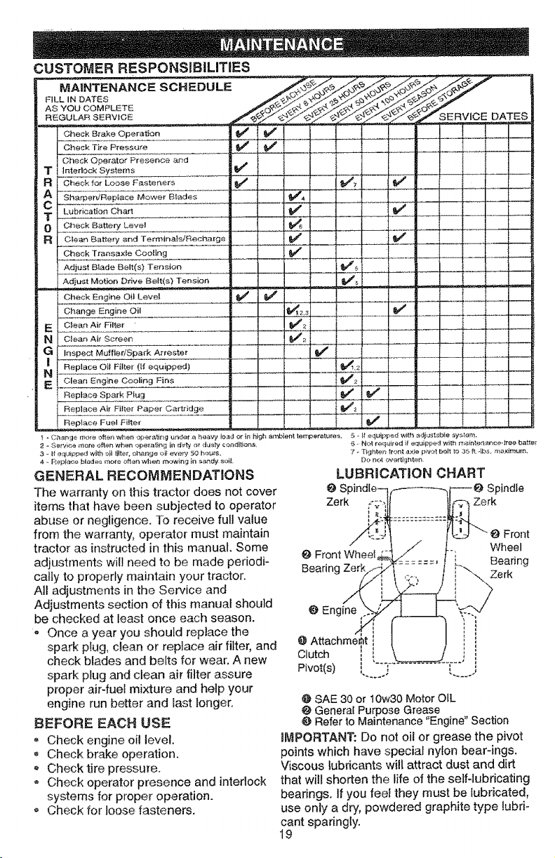
Front
Wheel
@ Front Wheel
Bearing
Bearing Zerk
Engine
@SAE 30 or I0w30 Motor OIL
@General Purpose Grease
Refer to Maintenance "Engine" Section
_MPORTANT: Do not oil or grease the pivot
points which have special nylon bear-ings.
Viscous lubricants will attract dust and dirt
that wilt shorten the fife of the selfqubricating
bearings. If you feel they must be lubricated,
use only a dry, powdered graphite type lubri-
cant sparingly.
19
TRACTOR
Always observe safety rules when per-
forming any maintenance.
BRAKE OPERATION
If tractor requires more than six (6) feet
stopping distance at high speed in highest
gear, then brake must be adjusted. (See
"TO ADJUST BRAKE" in the Service and
Adjustments section of this manual).
TIRES
• Maintain proper air pressure in all tires
(See "PRODUCT SPECIFICATIONS"
on page 5 of this manual).
° Keep tires free of gasoline, oi!, or insect
control chemicals which can harm rub-
ber.
• Avoid stumps, stones, deep ruts, sharp
objects and other hazards that may
cause tire damage.
NOTE: To seal tire punctures and prevent
flat tires due to slow leaks, tire sealant
may be purchased from your local parts
dealer. Tire sealant also prevents tire dnj
rot and corrosion.
BLADE CARE
For best results mower blades must be
kept sharp. Replace bent or damaged
blades.
BLADE REMOVAL
Raise mower to highest position to allow
access to blades.
° Remove hex bolt, lock washer and flat
washer securing blade.
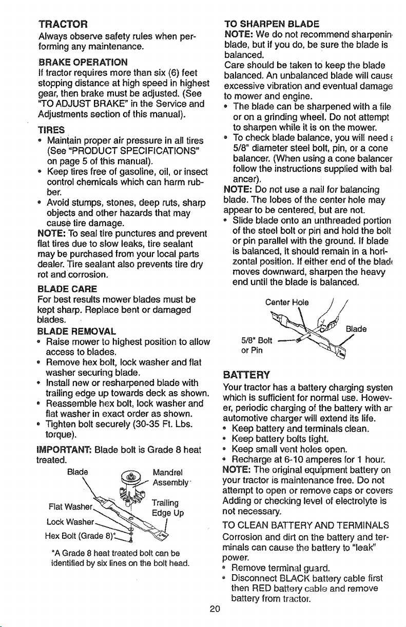
Install new or resharpened blade with
trailing edge up towards deck as shown.
, Reassemble hex bolt, lock washer and
fiat washer in exact order as shown.
* Tighten bolt securely (30-35 Ft. Lbs.
torque).
mMPORTANT: Blade bolt is Grade 8 heat
treated.
Blade _ Mandrel
_ _Assernbly"
_'_ Trailing
Flat EdgeUp
Hex Bolt (Grade 8)_..__ "_
*A Grade 8 heat treated bolt can be
identified by six lines on the bolt head,
TO SHARPEN BLADE
NOTE: We do not recommend sharpenin.
blade, but if you do, be sure the blade is
balanced.
Care should be taken to keep the blade
balanced. An unbalanced blade will caus_
excessive vibration and eventual damage
to mower and engine.
= The blade can be sharpened with a file
or on a grinding wheel. Do not attempt
to sharpen while it is on the mower.
To check blade balance, you will need
5/8" diameter steel bolt, pin, or a cone
balancer. (When using a cone balance[
follow the instructions supplied with bal
ancer),
NOTE; Do not use a nail for balancing
blade. The lobes of the center hole may
appear to be centered, but are not.
° Slide blade onto an unthreaded portion
of the steel bolt or pin' and hold the bolt
or pin parallel with the ground. If blade
is balanced, it should=remain in a hori-
zontal position, if either end of the blad_
moves downward, sharpen the heavy
end until the blade is balanced.
Center Hole
5/8" Bolt
or Pin
Blade
BATTERY
Your tractor has a batter,/charging systen
which is sufficient for normal use. Howev-
er, periodic charging of the battery with ar
automotive charger will extend its life.
- Keep battery and terminals clean.
Keep battery bolts tight.
, Keep small vent holes open.
Recharge at 6q0 amperes for 1 hour.
NOTE: The original equipment battery on
your tractor is maintenance free. Do not
attempt to open or remove caps or covers
Adding or checking level of electrolyte is
not necessary°
TO CLEAN BATTERY AND TERMINALS
Corrosion and dirt on the battery and ter-
minals can cause the battery to "leak"
power.
, Remove terminal guard.
Disconnect BLACK battery cable first
then RED battery cable and remove
battery from tractor.
2O
Rinsethebatterywithplainwaterand
dry.
Cleanterminalsandbatterycableends
with wire brush until bright.
, Coat terminals with grease or petroleum
jelly.
Reinstall battery (See "CONNECT BAT-
TERY" in the Assembly section of this
manual).
V-BELTS
Check V-belts for deterioration and wear
after 100 hours of operation and replace if
necessary. The belts are not adjustable.
Replace belts if they begin to slip from
wear.
TRANSAXLE COOLING
The transmission fan and cooling fins
should be kept clean to assure proper
cooling.
Do not attempt to clean fan or transmis-
sion while engine is running or while the
transmission is hot.
* inspect cooling fan to be sure fan
blades are intact and clean.
Inspect cooling fins for dirt, grass clip-
pings and other materials. To prevent
damage to seals, do not use com-
pressed air or high pressure sprayer to
clean cooling fins.
TRANSAXLE PUMP FLUID
The transaxle was sealed at the factory
and fluid maintenance is not required for
the life of the transaxle. Should the
transaxle ever leak or require servicing,
contact your nearest authorized service
center.
ENGINE
LUBRICATION
Only use high quality detergent oil rated
with API service classification SF, SG, or
SH. Select the oil's SAE viscosity grade
according to your expected operating tem-
perature.
SAE VI,5OOSITY G R_ADES
Change the oil after every 50 hours of
operation or at least once a year if the
tractor is not used for 50 hours in one
year.
Check the crankcase oil level before start-
ing the engine and after each eight (8)
hours of operation. Tighten oil fill cap/dip-
stick securely each time you check the oil
level.
TO CHANGE ENGINE OIL
Determine temperature range expected
before oil change. All oil must meetAPI
service classification SF, SG, or SH.
Be sure tractor is on level surface.
• Oil will drain more freely when warm.
Catch oil in a suitable container.
• Remove oil fill cap/dipstick. Be careful
not to allow dirt to enter the engine
when changing oi!.
Remove drain plug.
, After oil has drained completely, replace
oil drain plug and tighten securely.
• Refill engine with oil through oil fill dip-
stick tube. Pour slowly. Do not overfill.
For approximate capacity see "PROD-
UCT SPECIFICATIONS" on page 5 of
this manual.
• Use gauge on oil fill cap!dipstick for
checking level. Insert dipstick into the
tube and rest the oil fill cap on the tube.
Do not thread the cap onto the tube
when taking reading. Keep oil at
"FULL" line on dipstick. Tighten cap
onto the tube securely when finished.
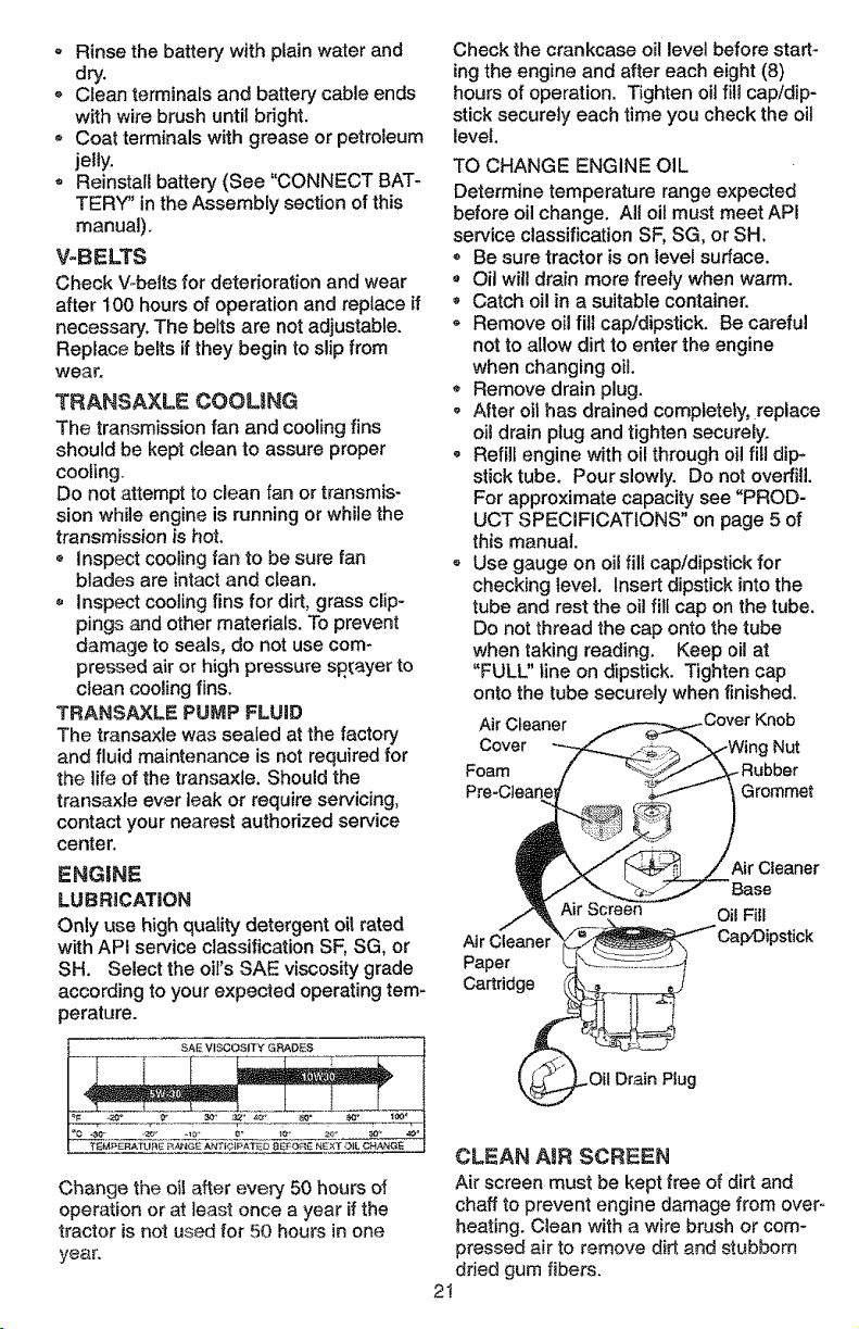
Air Cleaner Knob
Cover Nut
Foam
Grommet
Paper
Cartridge
Air Cleaner
Base
Oi! Fill
.Oil Drain Plug
CLEAN AIR SCREEN
Air screen must be kept free of dirt and
chaff to prevent engine damage from over-
heating. Clean with a wire brush or com-
pressed air to remove dirt. and stubborn
dried gum fibers.
2t
CLEAN AIR INTAKE/COOLING AREAS
To insure proper cooiing, make sure the
grass screen, cooling fins, and other
external surfaces of the engine are kept
clean at all times.
Every !00 hours of operation (more often
under extremely dusty, dirty conditions),
remove the blower housing and other
cooling shrouds. Clean the cooling fins
and external surfaces as necessary. Make
sure the cooling shrouds are reinstalled.
NOTE: Operating the engine with a
blocked grass screen, dirty or plugged
cooling fins, and/or cooling shrouds re-
moved will cause engine damage due to
overheating.
AIR FILTER
Your engine will not run properly using a
dirty air filter. Clean the foam pre-cleaner
after every 25 hours of operation or every
season. Service paper cartridge every
100 hours of operation or every season,
whichever occurs first.
Service air cleaner more often under dusty
conditions.
* Remove knob and cover.
Remove wing nut and air cleaner from
base.
TO SERVICE PRE-CLEANER
Slide foam pre-cleaner off cartridge.
o Wash it in liquid detergent and water.
• Squeeze it dry in a clean cloth. Allow it
to dry,
- Saturate it in engine oil. Wrap it in
clean, absorbent cloth and squeeze to
remove excess oi!,
TO SERVICE CARTRIDGE
Replace a dirty, bent, or damaged car-
tridge.
NOTE: Do not wash the paper cartridge
or use pressurized air, as this wit! damage
the cartridge.
o Reinstall the pre-cfeaner (cleaned and
•oiled) over the paper cartridge.
Reassemble air cleaner, wing nut, cover
and tighten knob securely.
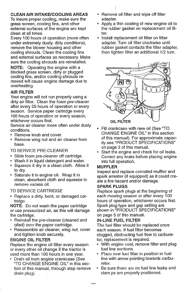
ENG_NE_O_L FILTER
Replace the engine oil filter every season
or every other oil change if the tractor is
used more than 100 hours in one year.
o Drain oil from engine crankcase (See
"TO CHANGE ENGINE O1L" in this sec-
tion of this manual, through step remove
drain plug).
o Remove oil filter and wipe off filter
adapter.
, Apply a thin coating of new engine oil to
the rubber gasket on replacement oil fit-
ter.
- Install replacement oil filter on filter
adapter. Turn oil filter clockwise until
rubber gasket contacts the filter adapter,
then tighten filter an additional i/2 turn.
• Fill crankcase with new oil (See "TO
CHANGE ENGINE OIL" in this section
of this manual). For approximate capac-
ity see "PRODUCT SPECIFICATIONS"
on page 3 of this manual.
, Start the engine and check for oil leaks.
Correct any leaks before placing engine
into full operation.
MUFFLER
Inspect and replace corroded muffler and
spark arrester (if equipped) as it could cre-
ate a fire hazard and/or damage,
SPARK PLUGS
Replace spark plugs at the beginning of
each mowing season or after even/100
hours of operation, whichever occurs first.
Spark plug type and gap setting are
shown in "PRODUCT SPECIFICATIONS"
on page 5 of this manual.
IN-LENE FUEL FILTER
The fuel filter should be replaced once
each season. If fuel filter becomes
clogged, obstructing fuel flow to carbure-
tor, replacement is required.
o With engine cool, remove filter and plug
fuen line sections.
o Place new fuel filter in position in fuel
_inewith arrow pointing towards carbu-
retor.
• Be sure there are no fuel line leaks and
cfam.ps are properly positioned.
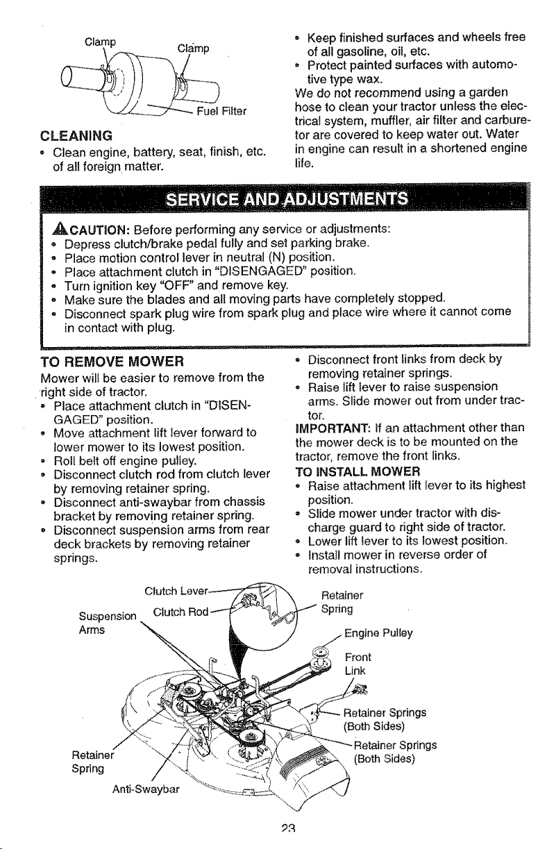
Clamp
__--- FuelFilter
CLEANING
• Clean engine, battery, seat, finish, etc.
of all foreign matter.
° Keep finished surfaces and wheels free
of all gasoline, oil, etc.
, Protect painted surfaces with automo-
tive type wax.
We do not recommend using a garden
hose to clean your tractor unless the elec-
trical system, muffler, air filter and carbure-
tor are covered to keep water out. Water
in engine can result in a shortened engine
life.
J_CAUTION: Before performing any service or adjustments:
° Depress clutch/brake pedal fully and set parking brake,
- Place motion control lever in neutral (N) position.
- Place attachment clutch in "DISENGAGED _position.
- Turn ignition key "OFF" and remove key.
= Make sure the blades and all moving parts have completely stopped.
° Disconnect spark plug wire from spark ptug and place wire where it cannot come
in contact with plug.
TO REMOVE MOWER
Mower will be easier to remove from the
right side of tractor.
= Place attachment clutch in "DISEN-
GAGED" positionl
• Move attachment lift lever forward to
lower mower to its lowest position.
, Roll belt off engine pulley.
, Disconnect clutch rod from clutch lever
by removing retainer spdng.
• Disconnect anti-swaybar from chassis
bracket by removing retainer spring.
o Disconnect suspension arms from rear
deck brackets by removing retainer
springs.
• Disconnect front links from deck by
removing retainer spdngs.
• Raise lift lever to raise suspension
arms. Slide mower out from under trac-
tor.
IMPORTANT: if an attachment other than
the mower deck is to be mounted on the
tractor, remove the front links.
TO iNSTALL MOWER
, Raise attachment lift lever to its highest
position.
o Slide mower under tractor with dis-
charge guard to right side of tractor.
, Lower lift lever to its lowest position.
-tnsta]l mower in reverse order of
removal instructions.
Suspension
Arms
\
Retainer
Spring
line Pulley
Front
Link
Retainer
Spring
Anti-Swaybar
Retainer Springs
(Both Sides)
Springs
(Both Sides)
TO LEVEL MOWER HOUSING
Adjust the mower while tractoris parked
on levelground or driveway.Make sure
tiresarepmpedy inflated(See "PROD-
UCT SPECIFICATIONS"). if tiresare
overor underinflated,you willnotproperly
adjustyourmower.
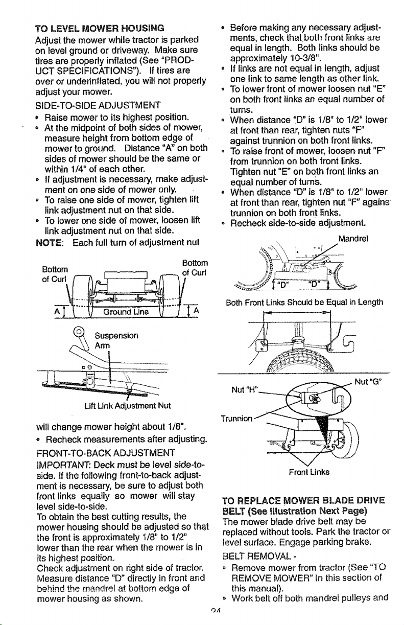
SIDE-TO-SIDE ADJUSTMENT
Raise mowerto its highest position.
At the midpoint of bothsides of mower,
measure height from bottom edgeof
mowerto ground. Distance "A" on both
sides of mowershouldbe the same or
within 1/4" of each other.
, if adjustmentis necessary, make adjust-
ment onone side of mower only.
To raiseone sideof mower, tightenlift
linkadjustmentnut on that side.
• To lowerone side of mower,loosen lift
linkadjustment nut on thatside.
NOTE: Eachfull turnof adjustment nut
Bottom
Bottom f Curl
of Cur|\_
, Before making any necessary adjust-
ments, check thatboth front links are
equal in length. Both links should be
approximately 10-3/8".
• if links are not equal in length, adjust
one link to same length as other link,
= To lower front of mower loosen nut "E"
on both front links an equal number of
turns.
• When distance ",D" is 1/8" to 1/2" lower
at front than rear, tighten nuts "F"
against trunnion on both front links.
• To raise front of mower, loosen nut "F"
from trunnion on both front links.
Tighten nut "E" on beth front links an
equal number of turnS.
• When distance "D" is 1t8" to I/2" lower
at front than rear, tighten nut "F" agains
trunnion on both front links.
• Recheck side-to-side adjustment.
Mandrel
Both FrontUnks Should be Equal in Length
Nut "G"
Lift Unk Adjustment Nut
will change mower height about 1/8".
• Recheck measurements after adjusting.
FRONT-TO-BACK ADJUSTMENT
IMPORTANT: Deck must be level side-to-
side. tf the following front-to-back adjust-
ment is necessary, be sure to adjust both
front links equally so mower will stay
level side-to-side.
To obtain the best cutting results, the
mower housing should be adjusted so that
the front is approximately I/8" to 1/2"
lower than the rear when the mower is in
its highest position°
Check adjustment on right side of tractor.
Measure distance "D" directly in front and
behind the mandrel at bottom edge of
mower housing as shown°
Trunnion
Front Links
TO REPLACE MOWER BLADE DRIVE
BELT (See illustration Next Page)
The mower blade drive belt may be
repmacedwithout tools. Park the tractor or
level surface. Engage parking brake.
BELT REMOVAL -
Remove mower from tractor (See "TO
REMOVE MOWER" in this section of
this manua!).
Work belt off both mandrel putieys and
O.4
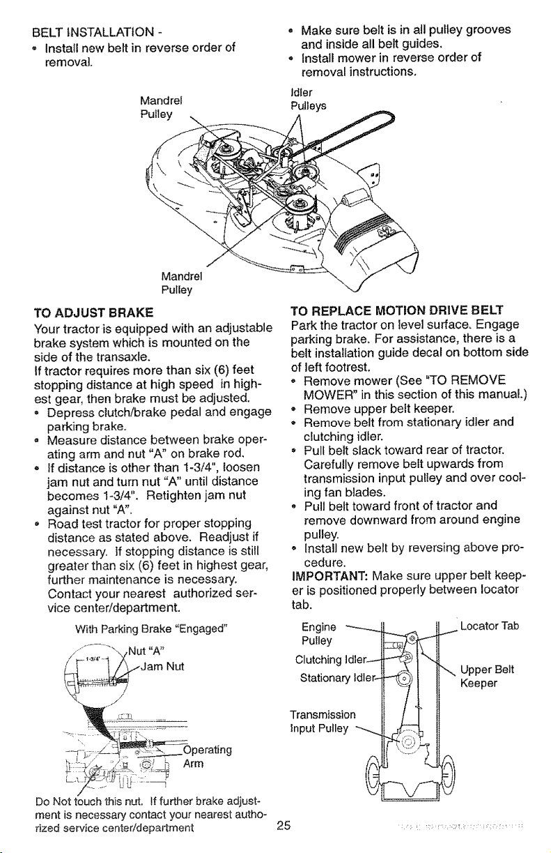
BELT INSTALLATION -
• Install new belt in reverse order of
removal.
Mandrel
Pulley
• Make sure belt is in all pulley grooves
and inside all belt guides.
. install mower in reverse order of
removal instructions.
Idler
Pulleys
Mandrel
Pulley
TO ADJUST BRAKE
Your tractor is equipped with an adjustable
brake system which is mounted on the
side of the transaxle.
If tractor requires more than six (6) feet
stopping distance at high speed in high-
est gear, then brake must be adjusted.
, Depress clutch/brake pedal and engage
parking brake.
, Measure distance between brake oper-
ating arm and nut "A" on brake rod,
* If distance is other than i-3/4", loosen
jam nut and turn nut "A" until distance
becomes 1-3/4". Retighten jam nut
against nut "A".
, Road test tractor for proper stopping
distance as stated above. Readjust if
necessary. If stopping distance is still
greater than six (6) feet in highest gear,
further maintenance is necessary,
Contact your nearest authorized ser-
vice centeddepartment,
With Parking Brake "Engaged"
_Jam Nut
..........]::?::_,/q_-! _,"_--Operating
Arm
Do Not touch this nut. If further brake adiust-
ment is necessary contact your nearest autho-
rized service centeddepartment
TO REPLACE MOTION DRIVE BELT
Park the tractor on level surface, Engage
parking brake, For assistance, there is a
belt installation guide decal on bottom side
of left footrest,
o Remove mower (See "TO REMOVE
MOWER" in this section of this manual,)
• Remove upper belt keeper.
Remove belt from stationary idler and
clutching idler.
• Pull belt slack toward rear of tractor.
Carefully remove belt upwards from
transmission input pulley and over cool-
ing fan blades,
Q Pull belt toward front of tractor and
remove downward from around engine
pulley,
Install new belt by reversing above pro-
cedure.
IMPORTANT: Make sure upper belt keep-
er is positioned properly between Iocator
tab.
Engine _.-..
Pulley
Clutching ldler_
Stationary Idler-
Transmission
input Pulley
i Locator Tab
",_ Upper Belt
Keeper
25
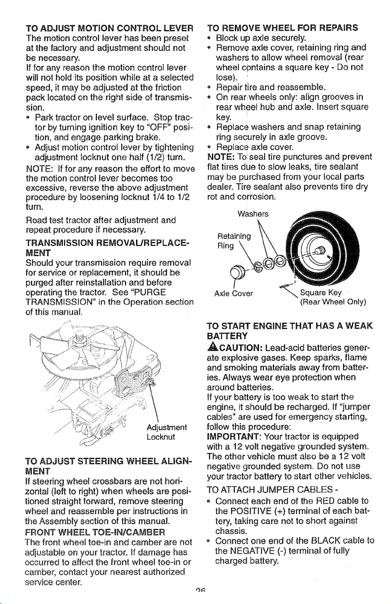
TO ADJUST MOTION CONTROL LEVER
The motion control lever has been preset
at the factory and adjustment should not
be necessary.
If for any reason the motion control lever
will not hold its position while at a selected
speed, it may be adjusted at the friction
pack located on the right side of transmis-
sion.
• Park tractor on level surface. Stop trac-
tor by turning ignition key to "OFF" posi-
tion, and engage parking brake.
o Adjust motion control lever by tightening
adjustment tocknut one half (1/2)turn.
NOTE: if for any reason the effort to move
the motion control lever becomes too
excessive, reverse the above adjustment
procedure by loosening Iocknut 1/4 to 1/2
turn.
Road test tractor after adjustment and
repeat procedure if necessary.
TRANSMISSION REMOVAL/REPLACE-
MENT
Should your transmission require removal
for service or replacement, it should be
purged after reinstallation and before
operating the tractor. See "PURGE
TRANSMISSION" in the Operation section
of this manual.
Adjustment
Locknut
TO ADJUST STEERING WHEEL ALiGN-
MENT
If steering wheel crossbars are not hori-
zontal (left to nght) when wheels are posi-
tioned straight forward, remove steering
wheel and reassemble per instructions in
the Assembly section of this manual.
FRONT WHEEL TOF=4N/OAMBER
The front wheel toe-in and camber are not
adjustable on your tractor. If damage has
occurred to affect the front wheel toeqn or
camber, contact your nearest authorized
service center.
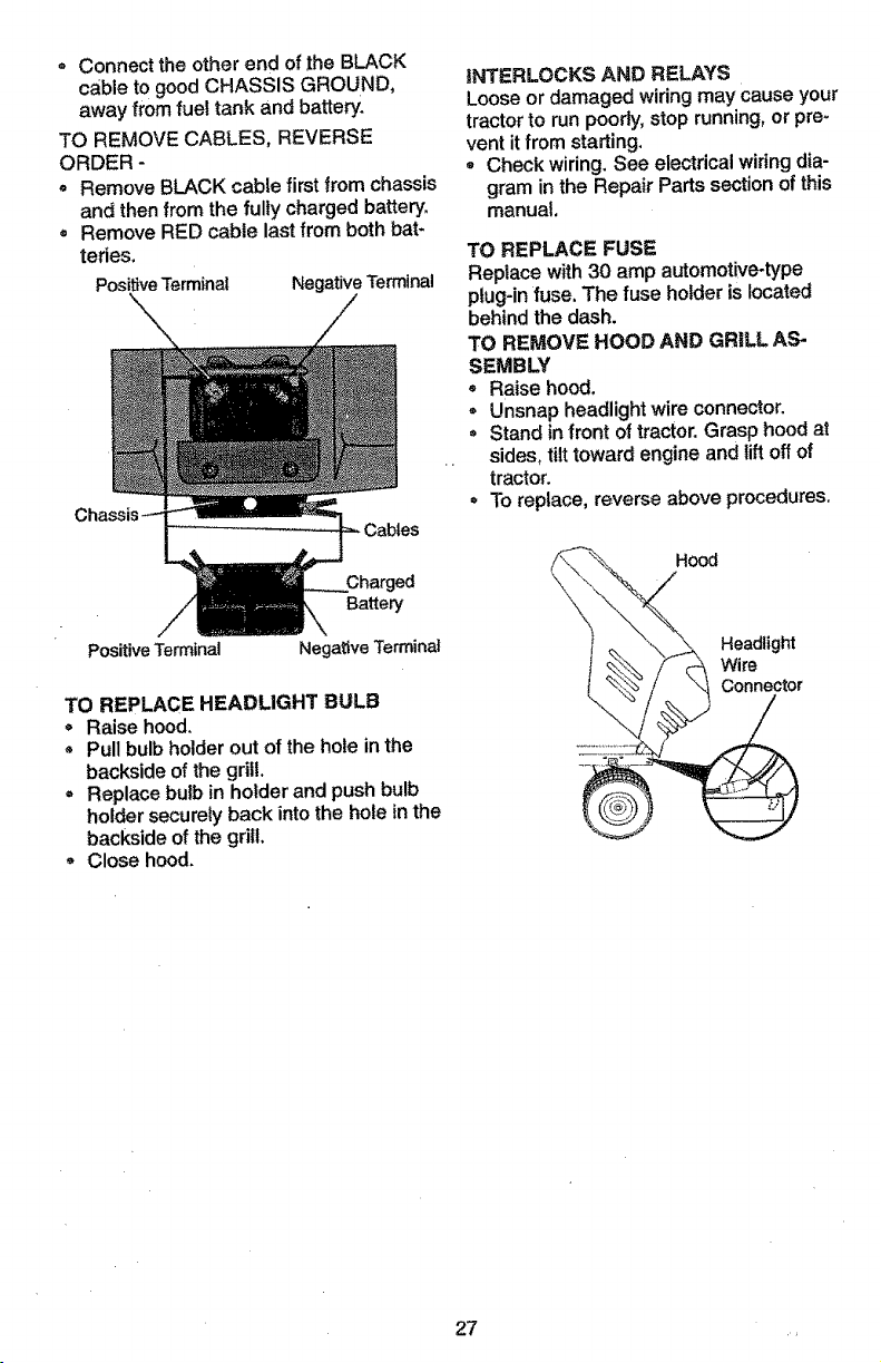
TO REMOVE WHEEL FOR REPAIRS
° Block up axle securely.
o Remove axle cover, retaining ring and
washers to allow wheel removal (rear
wheel contains a square key - Do not
lose).
- Repair tire and reassemble.
• On rear wheels only: align grooves in
rear wheel hub and axle. Insert square
key.
o Replace washers and snap retaining
ring securely in axle groove.
- Replace axle cover.
NOTE: To.seal tire punctures and prevent
flat tires due to slow leaks, tire sealant
may be purchased from your local parts
dealer. Tire sealant also prevents tire dry
rot and corrosion.
Washers
Ring \
Axle Cover
i
"_--_ Square Key
(Rear Wheel Only)
TO START ENGINE THAT HAS A WEAK
BATTERY
•_kCAUTION: Lead-acid batteries gener-
ate explosive gases. Keep sparks, flame
and smoking materials away from batter-
ies. Always wear eye protection when
around batteries.
If your battery is too weak to start the
engine, it should be recharged. If "jumper
cables" are used for emergency starting,
follow this procedure:
IMPORTANT: "Your tractor is equipped
with a 12 volt negative grounded system.
The other vehicle must also be a 12 volt
negative grounded system. Do not use
your tractor battery t° start other vehicles.
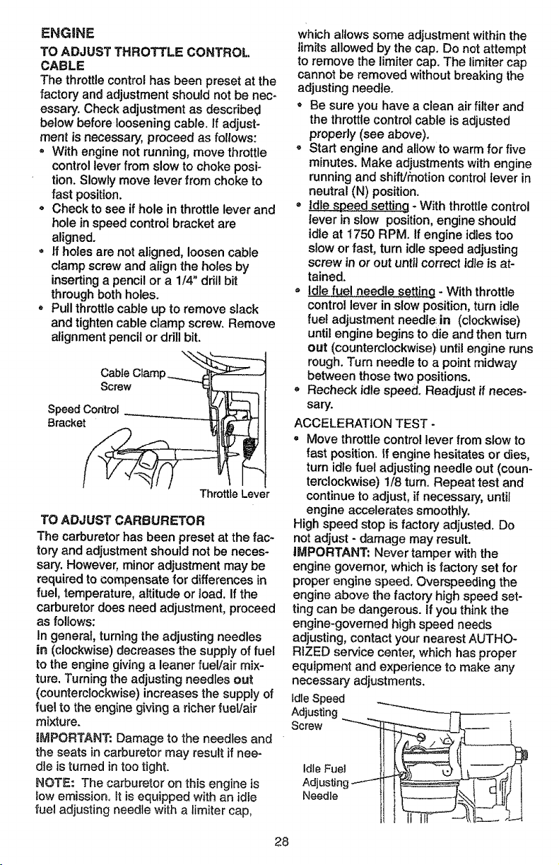
TO ATTACH JUMPER CABLES -
, Connect each end of the RED cable to
the POSITIVE (+) terminal of each bat-
tery, taking care not to short against
chassis.
Connect one end of the BLACK cable to
the NEGATIVE (-) terminal of fully
charged battery.
° Connecttheotherend of the BLACK
cable to good CHASSIS GROUND,
away from fuel tank and battery.
TO REMOVE CABLES, REVERSE
ORDER -
• Remove BLACK cable first from chassis
and then from the fully charged battery.
, Remove RED cable last from both bat-
tedes.
PositiveTerminal Negative Terminal
INTERLOCKS AND RELAYS
Looseor damaged wiringmay causeyour
tractorto run poorly,stoprunning,or pre-
vent itfrom starting.
- Check wiring.See electricalwiringdia-
gramin the RepairPartssectionof this
manual
TO REPLACE FUSE
Replace with30 amp automotive-type
plug-infuse. The fuse holderis located
behindthe dash.
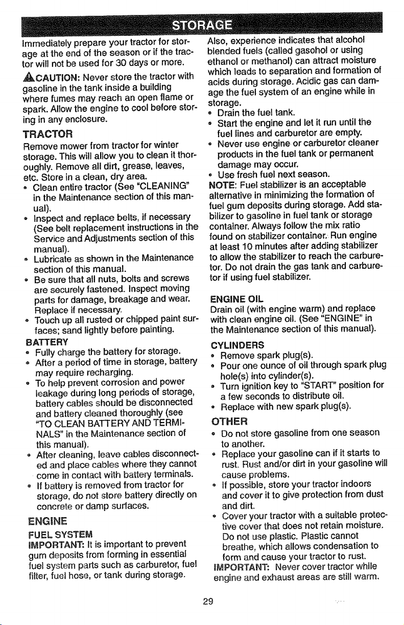
TO REMOVE HOOD AND GRILL AS-
SEMBLY
= Raisehood.
- Unsnapheadlightwire connector.
Standin front of tractor. Grasphood at
sides,tilt towardengineand lift offof
tractor.
Toreplace,reverse aboveprocedures.
Positive Terminal
Battery
Negative Terminal
TO REPLACE HEADUGHT BULB
Raise hood.
* Pull bulb holder out of the hole in the
backside of the grill.
, Replace bulb in holder and push bulb
holder securely back into the hole in the
backside of the gdlt.
Close hood.
Hood
Headlight
Wire
Connector
27
ENGINE
TO ADJUST THROTTLE CONTROL.
CABLE
The throttle control has been preset at the
factory and adjustment should not be nec-
essary. Check adjustment as described
below before loosening cable. If adjust-
ment is necessary, proceed as follows:
= With engine not running, move throttle
control lever from slow to choke posi-
tion. Slowly move lever from choke to
fast position.
• Check to see if hole in throttle lever and
hole in speed control bracket are
aligned.
- If holes are not aligned, loosen cable
clamp screw and align the holes by
inserting a pencil or a 1/4" drill bit
through both holes.
Pull throttle cable up to remove slack
and tighten cable clamp screw. Remove
alignment pencil or ddll bit.
Cab,eClamp_'_
Screw --I_
Throttle Lever
TO ADJUST CARBURETOR
The carburetor has been preset at the fac-
tory and adjustment should not be neces-
san]. However, minor adjustment may be
required to compensate for differences in
fuel, temperature, altitude or load. If the
carburetor does need adjustment, proceed
as follows:
In general, turning the adjusting needles
in (clockwise) decreases the supply of fuel
to the engine giving a leaner fuel!air mix-
ture. Turning the adjusting needles out
(counterclockwise) increases the supply of
rue! to the engine giving a richer fuel/air
mixture.
iMPORTANT: Damage to the needles and "
the seats in carburetor may result if nee-
die is turned in too tight.
NOTE: The carburetor on this engine is
fow emission. It is equipped with an idle
fue! adjusting needle with a fimiter cap,
28
which allows some adjustment within the
limits allowed by the cap. Do not attempt
to remove the limiter cap. The iimiter cap
cannot be removed without breaking the
adjusting needle.
* Be sure you have a clean air filter and
the throttle control cable is adjusted
properly (see above).
- Start engine and allow to warm for five
minutes. Make adjustments with engine
running and shiftJfnotion control lever in
neutral (N) position.
* Idle speed setting - With throttle control
lever in slow position, engine should
idle at 1750 RPM. if engine idles too
slow or fast, turn idle speed adjusting
screw in or out unti_ correct idle is at-
tained.
Idle fu_! _edte setting - With throttle
control lever in slow position, turn idle
fuel adjustment needle in (clockwise)
until engine begins to die and then turn
out (counterclockwise) until engine runs
rough. Turn needle to a point midway
between those two positions.
,, Recheck idle speed. Readjust if neces-
sary.
ACCELERATION TEST -
° Move throttle control lever from slow to
fast position. If engine hesitates or dies,
turn idle fuel adjusting needle out (coun-
terclockwise) 1/8 turn. Repeat test and
continue to adjust, if necessary, until
engine accelerates smoothly.
High speed stop is factory adjusted. Do
not adjust - damage may result.
iMPORTANT: Never tamper with the
engine governor, which is factory set for
proper engine speed. Overspeeding the
engine above the factory high speed set-
ting can be dangerous. If you think the
engine-governed high speed needs
adjusting, contact your nearest AUTHO-
RIZED service center, which has proper
equipment and experience to make any
necessary adjustments.
Idle Speed
Adjusting
Screw "_--_'_-
idle Fuel
Adjusting
Needle
Immediately prepare your tractor for stor-
age at the end of the season or if the trac-
tor will not be used for 30 days or more.
,_CAUTION: Never store the tractor with
gasoline in the tank inside a building
where fumes may reach an open flame or
spark. AUow the engine to cool before stor-
ing in any enclosure.
TRACTOR
Remove mower from tractor for winter
storage. This will allow you to clean it thor-
oughly. Remove all dirt, grease, leaves,
etc. Store in a clean, dry area.
* Clean entire tractor (See "CLEANING"
in the Maintenance section of this man-
ual).
- Inspect and replace belts, ff necessary
(See belt replacement instructions in the
Service and Adjustments section of this
manual).
Lubricate as shown in the Maintenance
section of this manual.
° Be sure that atl nuts, bolts and screws
are securely fastened, inspect moving
parts for damage, breakage and wear.
Replace if necessary.
o Touch up all rusted or chipped paint sur-
faces; sand lightly before painting.
BATTERY
* Fully charge the battery for storage.
After a period of time in storage, battery
may require recharging.
* To help prevent corrosion and power
leakage during long periods of storage,
battery cables should be disconnected
and battery cleaned thoroughly (see
"TO CLEAN BATTERY AND TERMI-
NALS" in the Maintenance section of
this manual).
, After cleaning, leave cables disconnect-
ed and place cables where they cannot
come in contact with battery terminals.
o if battery is removed from tractor for
storage, do not store battery directly on
concrete or damp surfaces.
ENG|NE
FUEL SYSTEM
iMPORTANT: It is important to prevent
gum deposits from forming in essential
fuet system parts such as carburetor, fuel
filter, fuel hose, or tank during storage.
Also, experience indicates that alcohol
blended fuels (called gasohol or using
ethanol or methanol) can attract moisture
which leads to separation and formation of
acids during storage. Acidic gas can dam-
age the fuel system of an engine while in
storage,
Drain the fuel tank.
* Start the engine and let it run until the
fuel lines and carburetor are empty.
* Never use engine or carburetor cleaner
products in the fuel tank or permanent
damage may occur.
, Use fresh fuel next season.
NOTE: Fuel stabilizer is an acceptable
alternative in minimizing the formation of
fuel gum deposits during storage. Add sta-
bilizer to gasoline in fuel tank or storage
container. Always follow the mix ratio
found on stabilizer container. Run engine
at least 10 minutes after adding stabilizer
to allow the stabilizer to reach the carbure-
tor. Do not drain the gas lank and carbure-
tor if using fuel stabilizer.
ENGINE OIL
Drain oil (with engine warm) and replace
with clean engine oil. (See "ENGINE" in
the Maintenance section of this manual).
CYLINDERS
o Remove spark plug(s).
° Pour one ounce of oil through spark plug
hole(s) into cylinder(s).
* Turn ignition key to "START" position for
a few seconds to distribute oil.
° Replace with new spark plug(s).
OTHER
o Do net store gasoline from one season
to another.
= Replace your gasoline can if it starts to
rust. Rust and/or dirt in your gasoline will
cause problems.
, If possible, store your tractor indoors
and cover it to give protection from dust
and dirt.
o Cover your tractor with a suitable protec-
tive cover that does not retain moisture.
Do not use plastic. Plastic cannot
breathe, which allows condensation to
form and cause your tractor to rust.
IMPORTANT: Never cover tractor while
engine and exhaust areas are still warm.
29
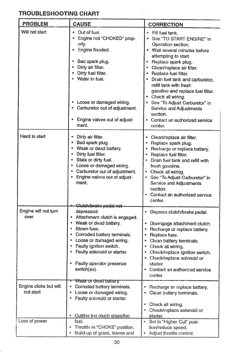
TROUBLESHOOTING CHART
-'C-AUSE
t¢ill not start _ Out of fuel.
,, Engine not "CHOKED" prop-
erly.
= Engine flooded.
Hard to start
Engine will not turn
over
Engine clicks but will
not start
Loss of power
Bad spark plug.
Dirty air filter.
Dirty fuel filter.
Water in fuel.
o Loose or damaged wiring.
, Carburetor out of adjustment.
* Engine valves out of adjust-
ment.
Dirty air filter_
o Bad spark plug.
Weak or dead battery.
o Dirty fuel filter.
Stale or dirty fuel.
, Loose or damaged wiring.
, Carburetor out of adjustment.
• Engine valves out of adjust-
ment.
depressed.
- Attachment clutch is engaged.
- Weak or dead battery.
._ Blown fuse.
• Corroded battery terminals.
• Loose or damaged wiring.
, Faulty ignition switch.
• Faulty solenoid or starter.
Faulty operator presence
switch(es).
Corroded battery terminals.
Loose of' damaged widng.
Faulty solenoid or starter.
o C uuttinq t£,9_.much_assitoo
fast.
Th[ottk_ in "CHOKE" position.
, Bui_d-up of grass, leaves and
30
CORRECTION
Fill fuel tank.
See "TO START ENGINE" in
Operation section.
= Wait several minutes before
attempting to start.
, Replace spark plug.
, Clean/replace air filter.
. Replace fuel filter.
• Drain fuel tank and carburetor,
refill tank with fresh
gasoline and replace fuel fitter.
° Check all wiring.
, See "To Adjust Carburetor" in
Service and Adjustments
section.
Contact an authorized service
center.
, Clean!replace air filter.
* Replace spark plug.
* Recharge or replace battery.
* Replace fuel filter.
, Drain fuel tank and refill with
fresh gasoline.
* Check all wiring.
, See _ToAdjust Carburetor" in
Service and Ad)ustrnents
section.
* Contact an authorized service
center.
* Oep_'ess clutch/brake pedal
- Disengage attachment clutch.
, Recharge or replace battery.
* Replace fuse.
, Ctean battery terminals.
* Check all wiring.
, Check/replace ignition switch.
* Checl_Jreplace solenoid or
starter.
, Contact an authorized service
center.
_ =
, Recharge or repiace batte_.
- Cle.an battery te_'minals.
Check a_lwidng.
Checkfreplace solenoid or
_st_rt_eL
* Set in "Higher cur' posi-
tion/reduce speed.
Adjust throttle control
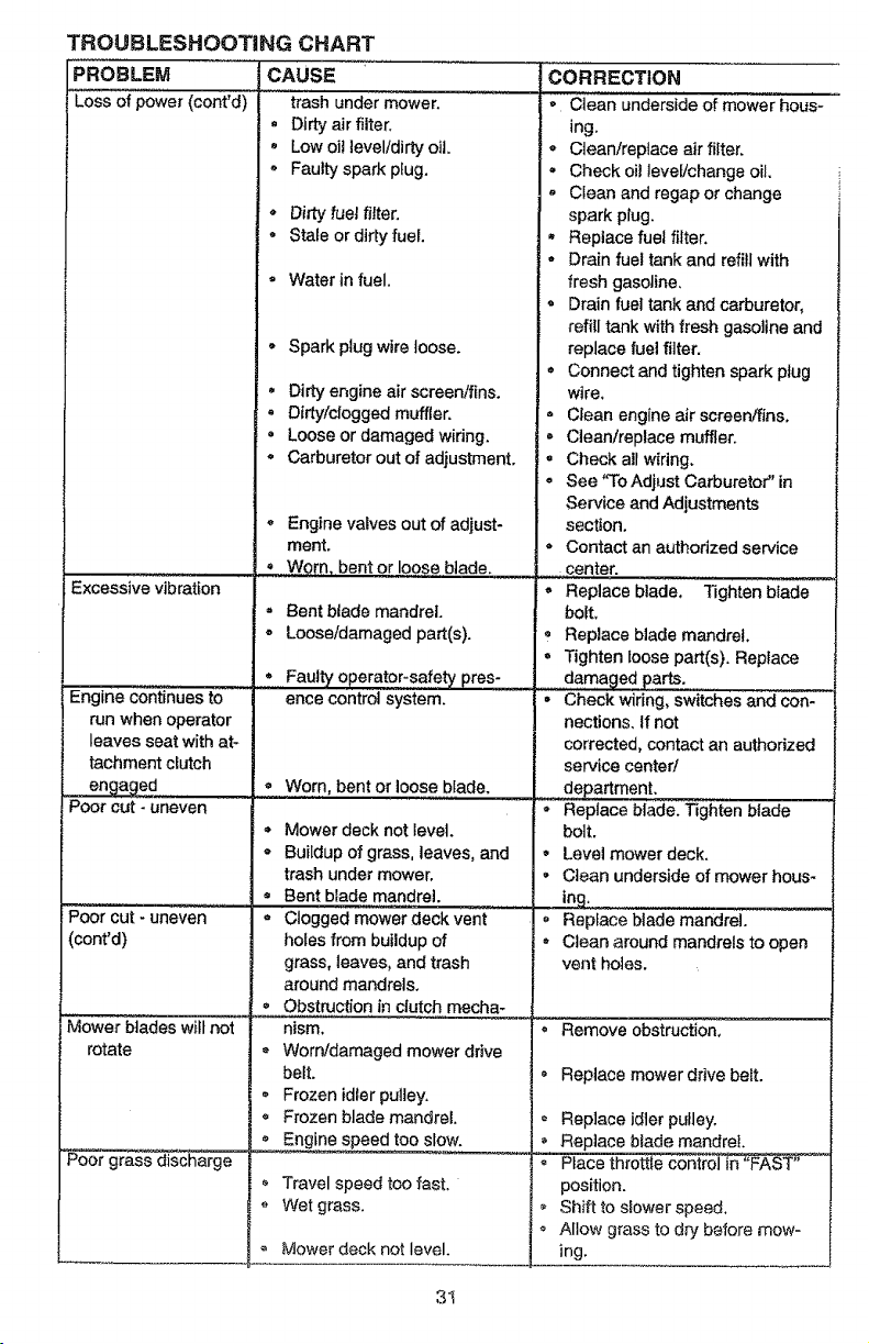
TROUBLESHOOTING CHART
PROBLEM CAUSE
i Lossof power(cont'd) trash under mower.
+ Dirtyair filter.
+ Low o]tlevel/dirtyoil.
+ Faulty spark plug.
Excessive vibration
° Dirty"fueJ lifter.
= Stale or dirty fuel.
+ Water in fuel.
Spark plug wire loose.
. Dirty engine air screen/fins.
+ Dirty/clogged muffler.
+ Loose or damaged wiring.
• Carburetor out of adjustment.
+ Engine valves out of adjust-
ment.
CORRECTION
o Clean underside of mower hous-
ing.
- CJean/replace air filter.
+ Check oil level/change oil.
. Clean and regap or change
spark plug,
. Replace fuel filter.
° Drain fuel tank and refill with
fresh gasoline,
. Drain fuel tank and carburetor,
refitl tank with fresh gasoline and
replace fuel filter.
+ Connect and tighten spark plug
wire,
= Clean engine air screen/fins.
= Clean/replace muffler.
+ Check all wiring.
• See 'q'o Adjust Carburetor" in
Service and Adjustments
section.
• Contact an authorized service
Poor cut +uneven
Engine continues to
run when operator
leaves seat with at-
tachment clutch
engaged +
Poor cut - uneven
e
o
e
Worn, bent or loose blade. , ...............center.
- Replace blade,
Bent blade mandrel.
Loose/damaged part(s).
Faulty operator-safety pres-
ence control system. •
Worn, bent or loose blade.
e
Mower deck not level.
Buildup of grass, leaves, and
trash under mower,
Bent blade mandrel.
Clogged mower deck vent
Tighten blade
bolt+
+ Replace blade mandrel.
. Tighten loose part(s). Replace
damaged parts.
Check wiring, switches and con-
nections. If not
corrected, contact an authorized
service center/
department.
Replace blade. Tighten blade
bolt.
. Level mower deck.
• Clean underside of mower hous+
in,
Replace blade mandrel.
(cont'd)
Mower blades wilt not
rotate
_rass discharge
holes from buildup of
grass, leaves, and trash
around mandrels+
+ Obstruction in clutch mecha-
nism.
+ Worn/damaged mower drive
belt.
= Frozen id+er pulley,
+ Frozen blade mandrel,
° Engine speed too slow.
Travel speed too fast.
+ Wet grass.
+ Mower deck not level.
e
e
8
e
e
Clean around mandrels to open
vent holes.
Remove obstruction,
Replace mower drive belt.
Replace idler pulley.
Replace blade mandrel.
Place throttle control in "FAST"
position.
Shift to slower speed,
Allow grass to dry before mow-
ing.
31
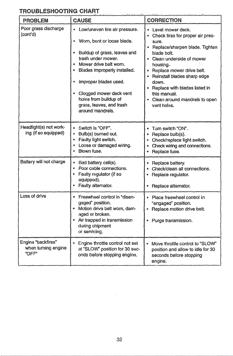
TROgBLESHOOTtNG CHART
PROBLE_
Poor grass discharge
(cont'd)
Headtight(s) not work-
ing (if so equipped)
Battery wUl not charge
Loss of drive
Engine "backfires"
when turning engine
"OFF"
CAUSE
Low/uneven tire air pressure.
® Worn, bent or ]oose blade,
* Buildup of grass, leaves and
trash under mower.
- Mower drive belt worn.
- Blades improperly installed.
Improper blades used.
Clogged mower deck vent
holes from buildup of
grass, leaves, and trash
around mandrels.
, Switch is"OFF",
* Bulb(s) burned out.
° Faulty light switch.
- Loose or damaged wiring,
, Blown fuse,
@
Bad battery celt(s).
Poor cable connections. ,
Faulty regulator (if so
equipped).
Faulty alternator.
- Freewheel control in "disen-
gaged" position.
,, Motion drive belt worn, dam-
aged or broken,
• A_r trapped in transmission
during shipment
or servicing.
CORRECTION
Level mower deck.
Check tires for proper air pres-
sure.
, Replace/sharpen blade. Tighten
blade bolt.
Clean underside of mower
housing..
, Replace mower drive belt.
, ReinstaU blades sharp edge
down.
, Replace with blades listed in
this manual
- Clean around mandrels to open
vent holes.
Engine throttfe control not set
at "SLOW" position for 30 sec-
onds before stopping engine.
• Turn switch "ON",
, Replace bulb(s)°
- Check/replace light switch.
, Check wiring and connections.
Replace fuse.
Replace battery.
Check!clean aH connections.
Replace regulator.
Replace alternator.
Place freewheel control in
"engaged" position.
Replace motion drive belt.
Purge transmission.
• Move throttle control to "SLOW"
position and allow to idte for 30
seconds before stopping
engine.
32
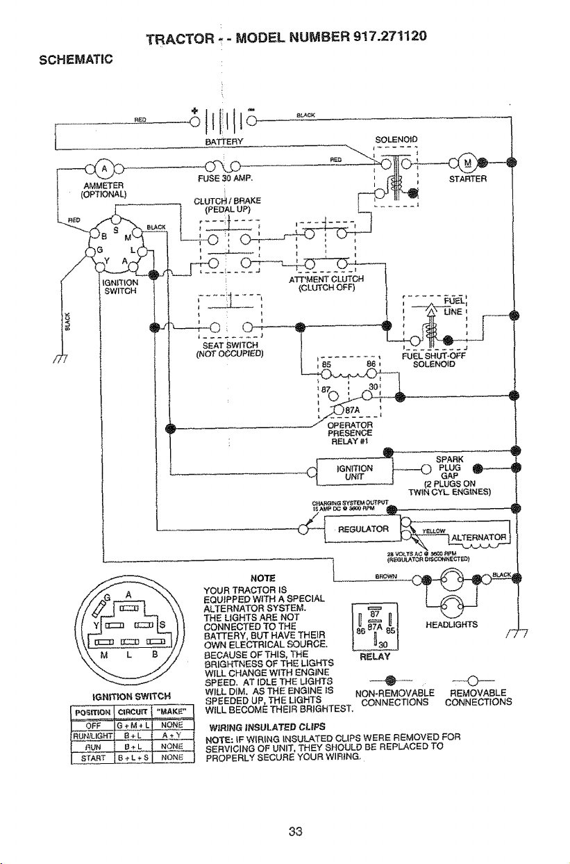
SCHEMATIC
TRACTOR - MODEL NU_,/tBEFt917.271120
BATTERY
-------_)0
AMMETER
(OPTIONAL)
t_kACK
,G
IGNITION
SWITCH
SOLENOID
FUSE 30 AMP. _ STARTER
t
|GNff|ON SWITCH
NOTE l
YOUR TRACTOR IS
EQUIPPED WITH A SPECIAL
ALTERNATOR SYSTEM.
THE LIGHTS ARE NOT
CONNECTED TO THE
BATTERY, BUT HAVE THEIR
OWN ELECTRICAL SOURCE.
BECAUSE OF THIS THE
BRIGHTNESS OF _E LIGHTS
WILL CHANGE WITH ENGINE
SPEED. AT IDLE THE LIGHTS + O"
WILL DIM. AS THE ENGINE IS NON+REMOVABLE REMOVABLE
SPEEDED UP, THE LIGHTS CONNECTIONS CONNECTIONS
WiLL BECOME THEIR BRIGHTEST.
2S VOkT,_AC _ _0t:_ _V'M
(R_GUkATQ_ DII_GONNECTED)
HEADLIGHTS f
RELAY
-7
WIRING INSULATED CLIPS
NOTE: tF WIRING INSULATED CLIPS WERE REMOVED FOR
SERVICING OF UNIT, THEY SHOULD BE REPLACED TO
PROPERLY SECURE YOUR WIRING,
33
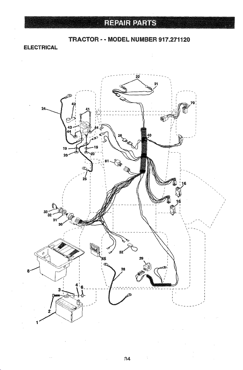
ELECTRICAL
TRACTOR - - MODEL NUMBER 917,271120
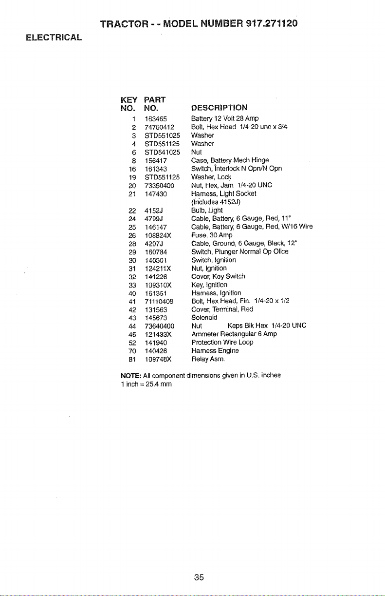
ELECTRICAL
TRACTOR - - MODEL NUMBER 917,271120
KEY PART
NO. NO.
1 163465
2 74760412
3 STD551025
4 STD551125
6 STD541025
8 156417
16 161343
19 STD551125
20 73350400
21 147430
22 4152J
24 4799J
25 146147
26 108824X
28 4207J
29 160784
30 140301
31 t24211X
32 141226
33 1093IOX
40 161351
41 71110408
42 131563
43 145673
44 73640400
45 t21433X
52 141940
70 140426
81 109748X
DESCRIPTION
Batter,/12 Vott 28 Amp
Bolt, Hex Head 1/4-20 unc x 3/4
Washer
Washer
Nut
Case, Battery Mech Hinge
Switch, interlock N Opn/N Opn
Washer, Lock
NUt, Hex, Jam 1/4-20 UNC
Harness, Light Socket
(Includes 4152J)
Bulb, Light
Cable, Battery, 6 Gauge, Red, I1"
Cable, Batte_, 6 Gauge, Red, W/16 Wire
Fuse, 30 Amp
Cable, Ground, 6 Gauge, Btack, t 2"
Switch, Piunger Normal Op Otice
Switch, Ignition
Nut, Ignition
Cover, Key Switch
Key, Ignition
Harness, Ignition
Bolt, Hex Head, Fin. 1/4-20 x t/2
Cover, Terminal, Red
Solenoid
Nut Keps BIk Hex t/4-20 UNC
Ammeter Rectangular 6 Amp
Protection Wire Loop
Harness Engine
Relay Asm.
NOTE: All component dimensions given in U.S. inches
1 inch = 25.4 mm
35
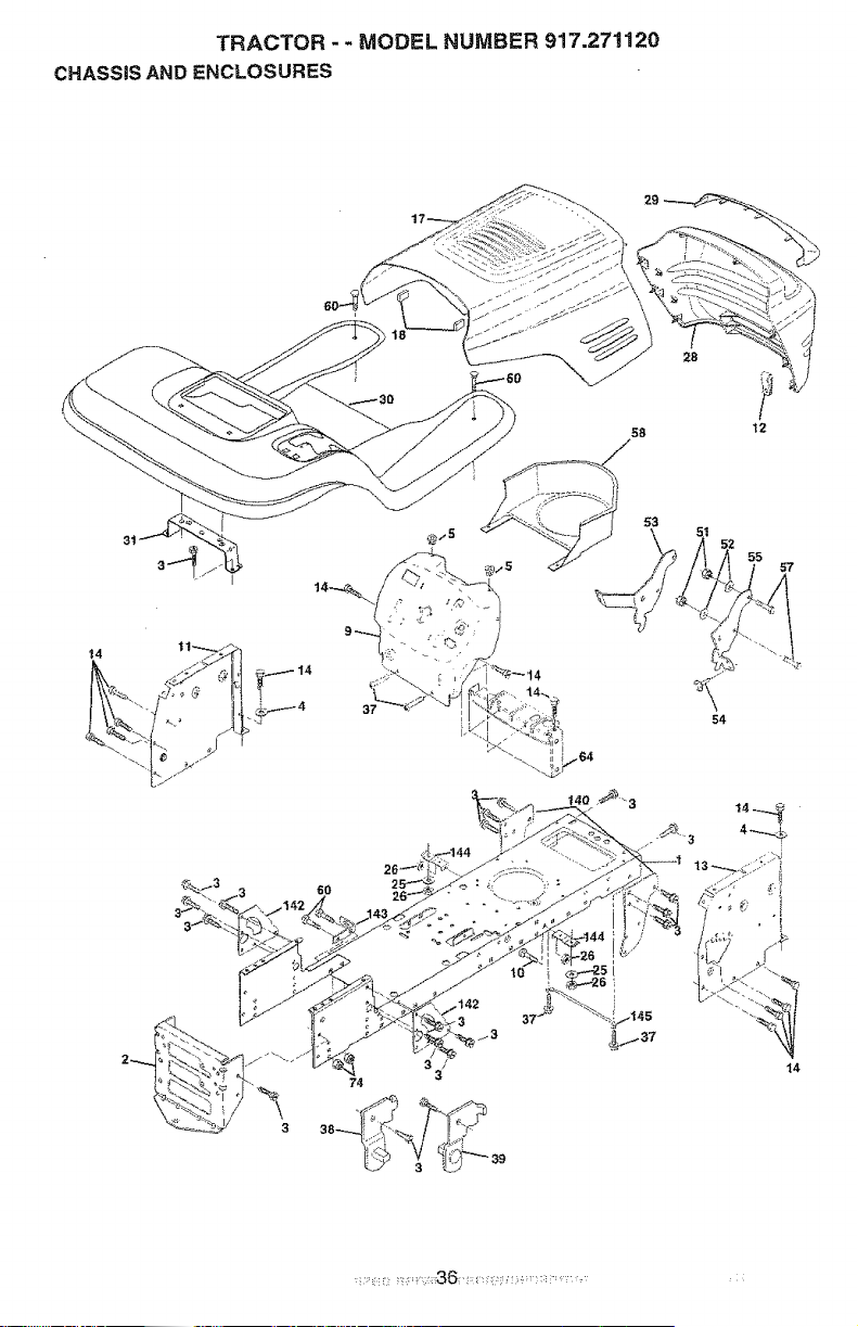
TRACTOR - - MODEL NUMBER 917.271120
CHASSIS AND ENCLOSURES
28
58 t2
54
6O
55
57
14
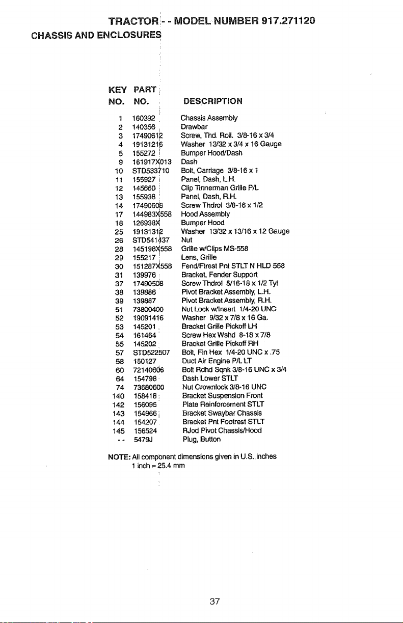
TRACTORi- - MODEL NUMBER 917.271120
CHASSIS AND ENCLOSURES
KEY PART
NO. NO.
t t 60392
2 140356 1
3 t74906t_:
4 1913121_
5 155272
9 1619t7X013
10 STD533710
1t 155927
12 145660
13 155936
14 1749060£
17 1449834558
18 t26938)_
25 1913131F2
26 STD541,437
28 145198)_558
29 155217 '
30 151287_558
31 139976
37 1749050£
38 139886
39 139887
51 73800400
52 19O9141-6
53 145201
54 161464
55 145202
57 STD522507
58 150127
60 72140606
64 154798
74 73680600
140 1584!6 '_
142 156095
143 154966
144 154207
145 156524
- - 5479J
DESCRIPTION
Chassis Assembly
Drawbar
Screw, Thd. RoE 3/8-t6 x 3/4
Washer t3/32 x 3/4 x 16 Gauge
Bumper Hood/Dash
Dash
Boit, Carriage 3/8-16 x t
Panel, Dash, L.H.
Clip _nnerman Gdtle P)L
Panet, Dash, R.H.
ScrewThdrot 3/8-16 x 1/2
Hood Assembly
Bumper Hood
Washer 13/32 × t3/16 x 12 Gauge
Nut
GdtLew!Clips M8-558
Lens, Grille
Fend/Ftrest Pnt STLT N HLD 558
Bracket, Fender Support
Screw Thdrol 6/16-18 x !/2 Tyt
Pivot Bracket Assembly, LH.
Pivot Bracket As_sembly, R.H.
Nut Lock w/tnsert 1/4-20 UNC
Washer 3/32 x 7/8 x 16 Ga.
Bracket Grille Pickoff LH
Screw Hex Wshd 8-t8 x 7/8
Bracket Gdfle Pickoff RH
Bo_, Fin Hex I/4-20 UNC x ,75
Duct Air Engine P/L LT
Bolt Rdhd Sqnk 3/8-t6 UNC x 3/4
Dash Lower STLT
Nut Crowntock 3/8-t6 UNC
Bracket Suspension Front
Plate Reinforcement STLT
Bracket Swaybar Chassis
Bracket Pnt FootreSt STLT
RJod Pivot Chassis/Hood
Plug, Button
NOTE: All component dimensions given in U.S. inches
1 inch = 25.4 mm
37
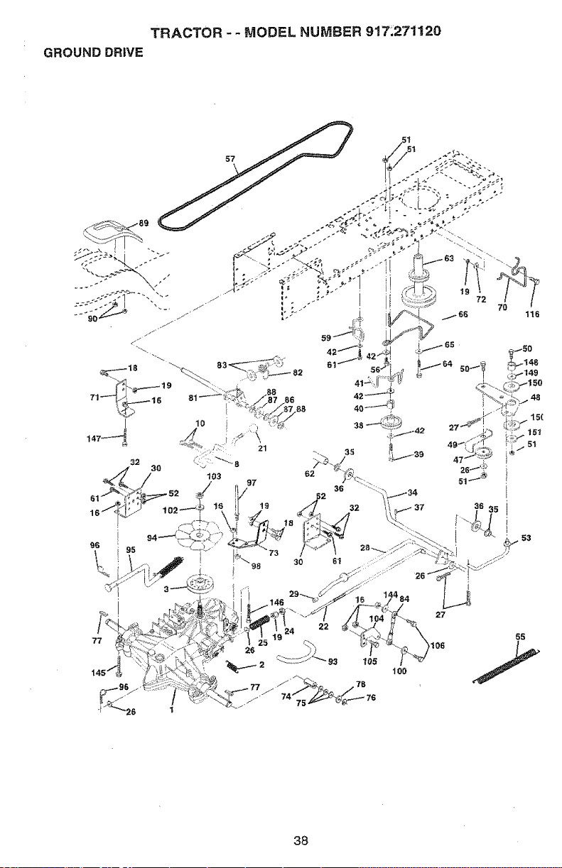
GROUND DRIVE TRACTOR.. MODEL NUMBER 9!7;271120
57
32 ' • ' :':<'": 21
38
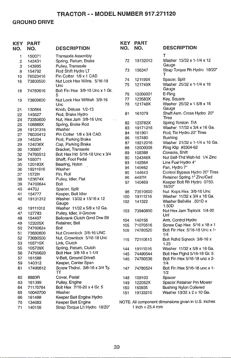
TRACTOR - - MODEL NUMBER 917,271120
GROUND DRIVE
KEY PART KEY PART
NO, NO. DESCRIPTION NO. NO.
1 150071 Transaxte Assembly
2 142431 Spring, Return, Brake 72 19132012
3 143995 Pulley, Transaxle
8 154792 Rod Shift Hydro LT 73 156347
!0 76020416 Pin Cotter I/8 x 1 CAD
16 73800500 Nut Lock HexWfins. 5/16-18 74 121199X
Unc 75 121749X
18 74780616 Bolt Fin Hex 3/8-16 Unc x 1 Gr.
5 76 1200000t
t9 73800600 Nut Lock Hex W/Wsh 3/8-I6 77 123583X
Unc 78 121748X
21 130564 Knob, Deluxe !/2-!3
22 145627 Rod, Brake Hydro 81 161079
24 73350600 Nut, HexJam 3/8-t6 Unc ..
25 106888X Spring, Brake Rod 82 123782X
26 19131316 Washer 83 19171216
27 76020412 PinCotter 1/8 x3/4 CAD. 84 16190!
28 145204 Rod, Parking Brake 86 157480
29 124236X Cap, Parking Brake 87 192t2016
30 130807 Bracket, Transaxle 88 t2000008
32 74760512 BoIt Hex Hd 5/t6-18 Unc x 3/4 89 t58388
34 155071 Shaft, Foot Pedal 90 t24346X
35 120183X Bearing, Nylon 93 142564
36 19211616 "Washer 94 140462
37 1572H Pin, Rolt 95 144643
38 123674X Pulley, |dle£ Flat 96 4497H
39 74760644 Bolt 97 140469
40 4470J Spacer, Split 98 73510600
4t 154777 Keeper, Bettldter 100 19111216
42 19131312 Washer 13/32 x 13/16 x 12
Gauge 102 141322
43 19111012 Washer I1/32 x 5/8 x 12 Ga.
47 127783 Pu{tey, Idler, V-G_aove 103 73940800
48 154407 Bellcrank Clutch Grad Drw St_
t04 140155
49 123205X Retainer, BeIt 105 71070516
50 74760624 Bolt
106 74780520
51 73680600 Nut Crowntock 3/8-16 UNC
52 73680500 Nut, Crownlock 5/16q8 Une 116 72110610
53 105710X Unk, C_utch
55 105709X Spring, Return, Ctutch t44 19111016
56 74760620 Bolt Hex 3/8-16 x 1-1/4 145 74490544
57 161688 V-BeI1, Ground Drive5 146 74780536
59 140312 Keeper, Center Span
61 17490612 ScrewThdroL 3i8q6x3i4Ty. 147 74780524
62 8883R Cover, Pedal 148 159103
63 161399 Pulley, Engine 149 122052X
64 71170764 Bolt Hex 7/t6-20 x 4 Gr. 5 !50 150935
65 10040700 Washer t51 19133210
66 161488 Keeper Belt Engine Hydro
70 134683 Keeper Belt Engine NOTE:
71 140158 Strap Torque Lh Hydro !8/20"
DESCRIPTION
T
Washer 13/32 x tol/4 x 12
Gauge
Strap Torque Rh Hydro 18/20"
T
Spacer, Split
Washer 25/32 x 1-t/4 x 16
Gauge
E-Ring
Key, Square
"Washer 25/32 x t-5/8 x 16
Gauge
Shaft Asm. Cross Hydro 20"
Tires
Spdng Torsion TiA
Washer 17/32 x 3/4 x 16 Ga,
Rod, Tie Hydro 20" Tires
Bushing
Washer 21/32 x 1-1/4 x 16 Ga.
Ring K_ip #5304-62
Console, Shift
Nut Self-Thd Wsh-hd 1/4 Zinc
Line Fuel Hydro 4"
Fan, Hydro 7"
Control Bypass Hydro 20" Tires
Retainer Spring t" Zinc/Cad
Keeper Bolt Rh Hydro 0750.
18/20"
Nut Keps Hex 3/8-!6 Unc
Washer 11/32 x 3/4 x 16 Ga.
Washer BeItviIIe .501 D x
1,50D
Nut Hex Jam Toplock 1/4-20
Unf
Arm, Control Hydro
Screw Cap Hex 5/16 x t8 x 1
Bolt Fin Hex 5/t6-18 Uncx t-
1/4
Boit Rdhd Sqneck 3/8-16 x
1,25
Washer 11/32 x 5/8 x 16 Ga.
Bolt Hex Flghd 5/t6-18 Gr. 5
Bolt Fin Hex 5/16-18 unc x 2_
!/4
Bolt Fin Hex 5/16-18 unc x 1-
1/2
Spacer
Spacer Retainer Pm Mower
Bushing Nylon Coitered
Washer !3/32 x 2 x 10 Ga,
Aii component dimensions given in U.S. inches
1 inch _ 25.4 mm
39
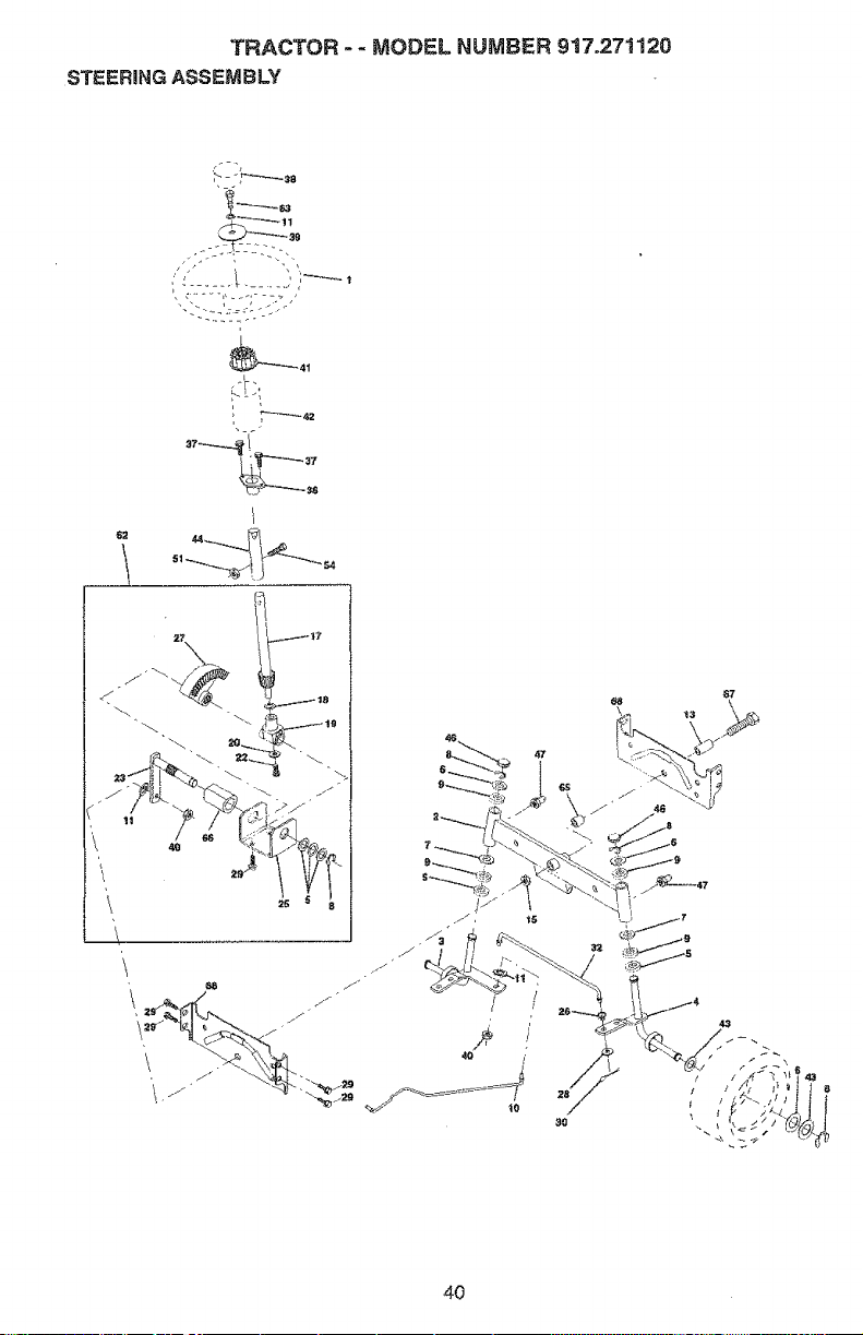
TRACTOR - - MODEL NUMBER 917.271120
STEERING ASSEMBLY
1
L
4O
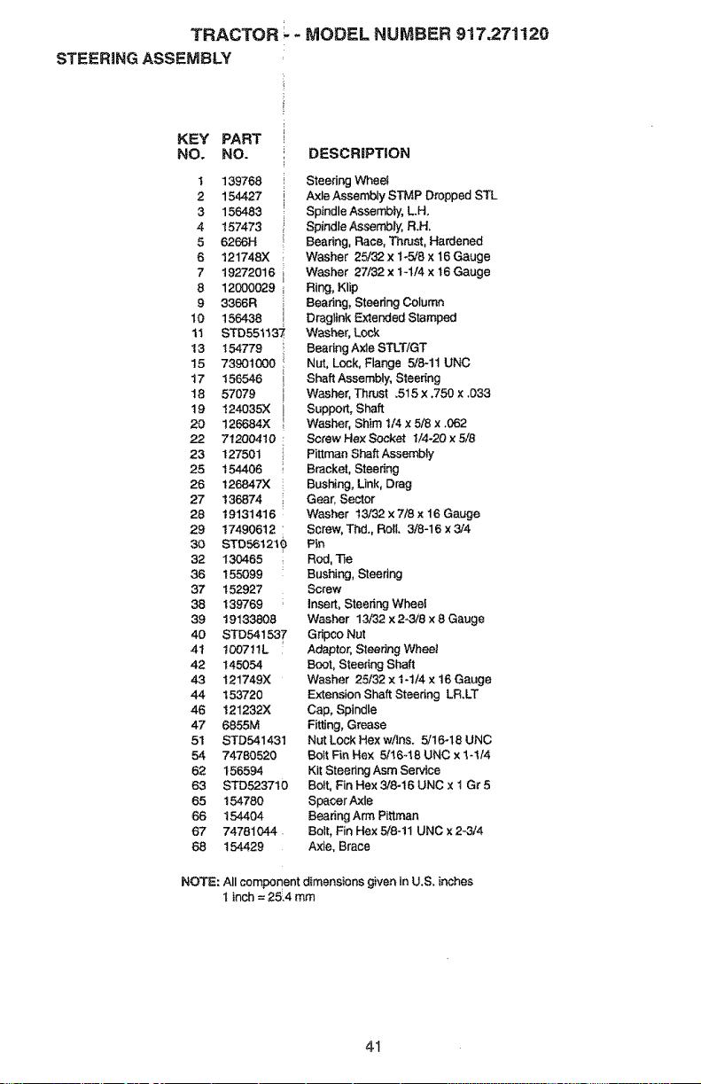
TRACTOR _- MODEL NUMBER 917,271120
STEERING ASSEMBLY
KEY PART
NO. NO.
1
2
3
4
5
6
7
8
9
10
11
13
15
17
t8
t9
20
22
23
25
26
27
28
29
30
32
36
37
38
39
4O
4I
42
43
44
46
47
51
54
62
63
65
66
67
68
139768
154427
156483
157473
6266H
121748X
t 9272016
12000029
3366R
156438
STD551137,
154779 i
739otoooi
156546
57079
124035)(
126684X
71200410
127501
t 54406
t26847X
136874
19131416
17490612 :
STD5612t_)
130465
155099
152927
139769
19133808
STD541537
t007tlL
145054
t21749X
t 53720
121232X
6855M
STD541431
74780520
t 56594
STD523710
154780
154404
74781044
154429
DESCRiPTiON
Steering Wheet
Axle Assembly STMP Dropped STL
Spindle Assembly, L.H,
Spindle AssembhJ, R.H,
Bearing, Race, Thrust, Hardened
Washer 25/32 x 1_5/8 x 16 Gauge
Washer 27/32 x t-114 x 16 Gauge
Ring, Klip
Bearing, Steering Column
Dr_gtink F_xtended Stamped
Washer, Lock
Beadng Axle STLT/GT
Nut, Lock, Flange 5/8-tt UNC
Shaft Assembly, Steerir_cj
Washer, Tht_Jst .515 x ,750 x .033
Support, Shaft
Washer, Shim 1/4 x 5/8 x .062
Screw Hex Socket I/4-20 x 5/8
Pittrnan Shaft Assembty
Bracket, Steering
Bushing, Unk, Drag
Gear, Sector
Washer 13/32 x 7/8 x 16 Gauge
Screw, Thd. RoE 3/8-16 x 3/4
Pin
Rod, Tie
Bushing, Steedng
Screw
insert, Steering Wheel
Washer 13/32 x 2-3/8 x 8 Gauge
Gripeo Nut
Adaptor, SteerJng Wheat
Boot, Steering Shaft
Washer 25/32 x t-t/4 x t6 Gauge
Extension Shaft Steenng LR.LT
Cap, Spindle
Fitting, Grease
Nut Lock Hex w/Ins. 5/16-18 UNC
BOIt Fin Hex U16,18 UNC x 1-I/4
Kit Steering Asm Servia
Bolt, Fin Hex 3/846 UNC x t Gr 5
Spacer Axle
Bearing Arm Pittman
Bolt, Fin Hex 5/8-11 UNC x 2-3/4
Axle, Brace
NOTE: All component dimensions given in U.S. inches
I inch = 25!4 mm
41
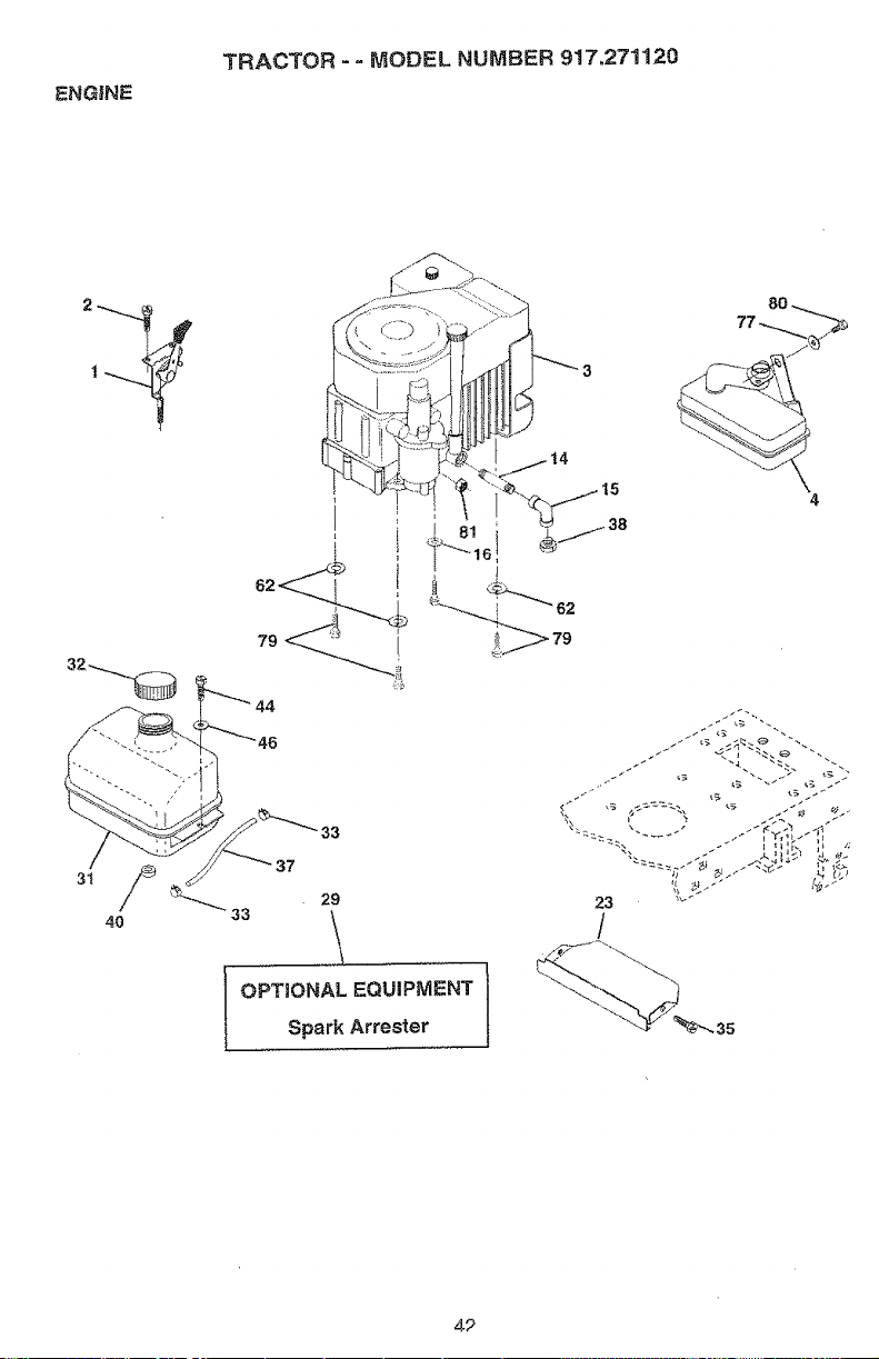
ENGINE
"TRACTOR "= MODEL NUMBER 917.271120
4
4/{_ _"_ 33
2.3
/
4P
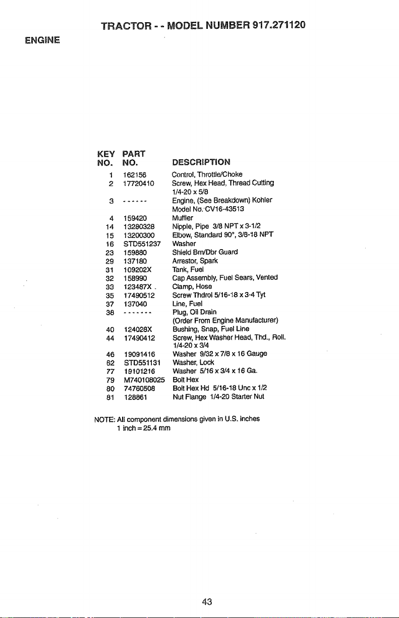
ENGINE
TRACTOR - - MODEL NUMBER 917.271120
KEY PART
NO. NO. DESCRIPTION
1 162156 Control, Throttle/Choke
2 17720410 Screw, Hex Head, Thread Cutting
1/4-20 x 5/8
3 ...... Engine, (See Breakdown) Kohler
Modet No:CV16-43513
4 t 59420 Muffler
14 13280328 Nipple, Pipe 3/8 NPT x 3-1/2
15 13200300 Elbow, Standard 90°, 3/8-t8 NPT
t6 STD551237 Washer
23 t59880 Shield Bm,/Dbr Gua_
29 137180 Arrestor, Spark
31 109202X Tank, Fuel
32 158990 Cap Assembly, Fuel Sears, Vented
33 123487X _ Clamp, Hose
35 17490512 Screw Thdrol 5/16-18 x 3-4 Tyt
37 137040 Line, Fuel
38 ....... Plug, OilDrain
(Order From Engine Manufacturer)
40 124028X Bushing, Snap, Fuel Line
44 17490412 Screw, Hex Washer Head, Thd. Roll.
t/4-20 x 3/4
46 19091416 Washer 9,/32 x 7/8 x 16 Gauge
62 STD55113t Washer, Lock
77 19101216 Washer 5/16x 3/4 x I6 Ga.
79 M740108025 Bolt Hex
80 74760508 Bolt Hex Hd 5/16-18 Unc x 1/2
81 128861 Nut Flange 1/4-20 Starter Nut
NOTE: All component dimensions given in U.S. inches
1 inch = 25.4 mm
43
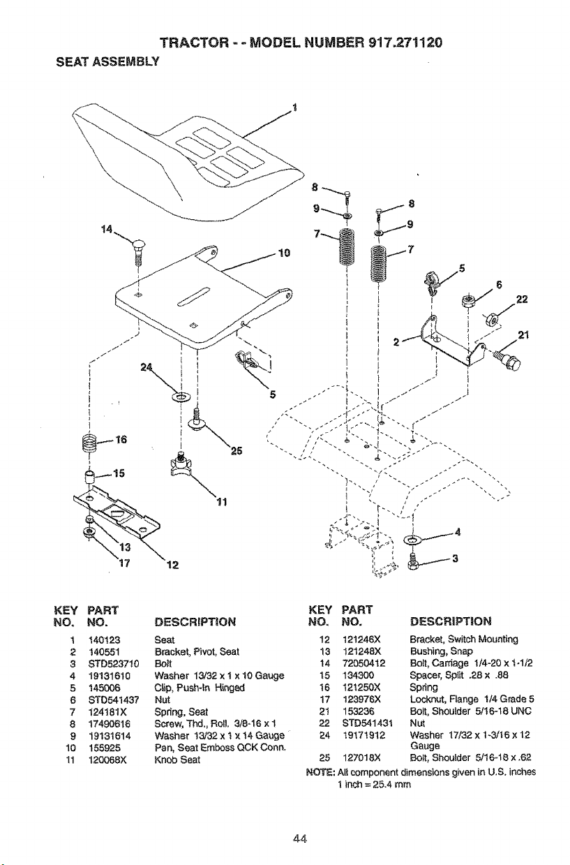
TRACTOR -- MODEL NUMBER 917.271120
SEATASSEMBLY
8
5
21
KEY
NO.
1
2
3
4
5
6
7
8
9
lo
11
PART KEY PART
NO. DESCRIPTION NO. NO. DESCRiPTiON
140123 Seat 12 121246X Bracket, Switch Mounting
140551 Bracket, PNot, Sea! 13 121248)( Bushing, Snap
STD523710 Bolt t4 72050412 Bolt, Carriage t/4-20 x t-1/2
19131610 Washer 13/32 × 1 × 10 Gauge 15 134300 Spacer, Split .28 x .88
145006 C_ip, Push-in Hinged 16 12t250X Spring
STD641437 Nut 17 123976X Locknut, Flange I/4 Grade 5
124t81X Spdng, Seat 2"J 153236 Bolt, Shouter 5/16-t8 UNC
17490616 Screw, Thd,, Re& 3/8-16 x I 22 STD541431 Nut
19131614 Washer I3/32 x t x t4 Gauge 24 19171912 Washer 17/32 x 1-3/16 x 12
155925 Pan, Seat Emboss QCK Conn. Gauge
120088X Knob Seat 25 127018)( BoLt, Shoulder 5/1648 x .62
NOTE: Alt component dimensions given ]n U.S. inches
I inch = 25.4 mm
44
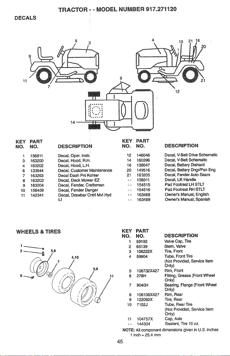
DECALS
TRACTOR -__ MODEL NUMBER 917.271120
IO
16
20
1!
12
2t
KEY
NO,
PART
NO,
t 156811
3 163200
4 163202
6 133644
7 163263
8 163203
9 163204
t0 i56439
tt 142341
14
KEY PART
DESCRIPT_ON NO. NO.
Decal, Oper. lns_r: 12 146046
Decal, Hood, R.H. 14 160396
Decal, Hood, L.H, 16 138047
Decal, Customer Maintenance 20 t49516
Decal Dash Pnl Kohfer 2t t63205
Decal, Deck Mower E.Z - - 138311
Decal, Fender, Craftsman - - 154515
Decal, Fender Danger - - 154516
Decal, Drawbar Cntd Mvt Hyd - - 163488
Lt - - 163489
DESCRiPTiON
Decal, V43e_ Drive Schematic
Decal, V-Belt Schematic
Decal, Battery Diehard
Decal, Battery DngrfPsn Eng
Deca!, Fender Auto Sears
Decal, Lift Handle
Pad Footrest LH STLT
Pad Footrest RH STLT
Owner's Manual, English
Owner's Manual, Spanish
4,10
tt
KEY PART
NO. NO, DESCRiPTiON
t 59192 Valve Cap, Tire
2 65139 Stem, Valve
3 t06222X Tire, Front
4 59904 Tube, Front Tire
(Not Provided, Service item
Oray)
5 I06732X427 Rim, Front
6 278H Fitting, Grease (Front Wheel
Only)
7 9040H Bearing, Flange (Front Wheel
Only)
8 106108X427 Rim, Rear
9 122082X Tire, Rear
10 7152J Tube, RearTire
(Not Provided, Service item
Only)
1t 104757X Cap, Axle
- - 144334 Sealant, Tire 10 oz.
NOTE: All component dimensions given in U.S. inches
I inch = 25.4 mm
45
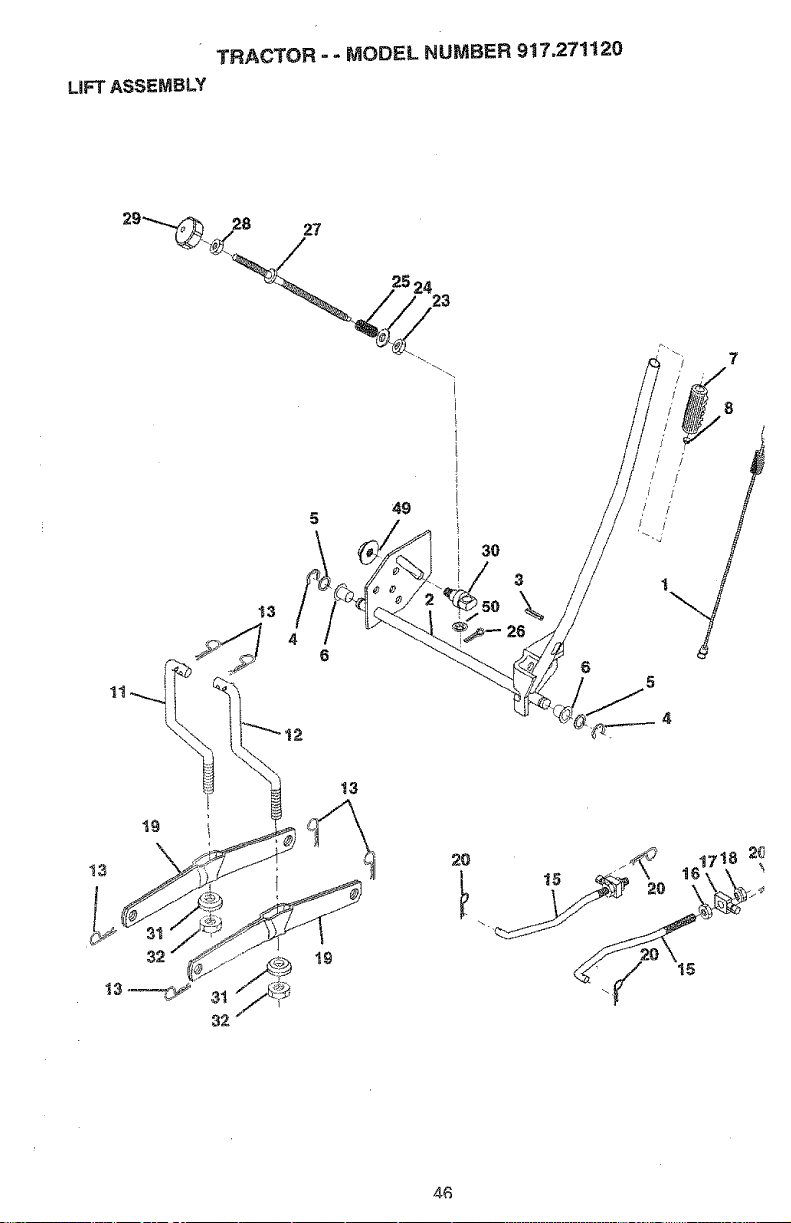
TRACTOR -- MODEL NUMBER 917o271120
LiFTASSEMBLY
27
25 24
23
30
3
\
7
8
32
32
13
15
4_
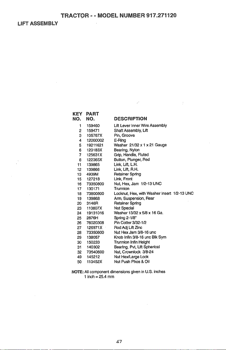
TRACTOR -- MODEL NUMBER 917.271120
LiFT ASSEMBLY
KEY PART
NO. NO. DESCRiPTiON
1 159460 Lift Lever InnerWire Assembly
2 159471 ShaftAssembly, Lift
3 105767X Pin, Groove
4 12000002 E-Ring
5 19211621 Washer 21/32 x 1 ×21 Gauge
6 120183)( Bearing, Nyl_
7 t2563tX Grip, Handle, Fluted
8 t22365X Button, Plunger, Red
11 139865 Link, Lift, L,H,
12 139866 Link, Lift, R.H.
13 4939M Retainer Spring
15 127218 Link, Front
t6 73350800 Nut, Hex, Jam 1/2-13 UNC
17 130171 Trunnion
t8 73800800 Locknut, Hex, with Washer Insert 1/2-13 UNC
t9 139868 Arm, Suspension, Rear
20 3t46R Retainer Spring
23 110807X Nut Speciat
24 19131016 Washer t3/32 x 5/8 x 16 Ga.
25 2876H Spring 2-1/8"
26 76020308 Pin Cotter 3/32-i/2
27 126971X RodAdj Lift Zinc
28 73350600 Nut Hex Jam 3/8-16 unc
29 138057 Knob Infin 3/8-16 unc Blk Sym
30 150233 Trunnion |nfin Height
31 140302 Bearing, Pvt, Lift Spherical
32 73540600 Nut, Crownlock 3/8-24
49 145212 Nut Hex/Large Lock
50 1t0452X Nut Push Phos & Oil
NOTE: Atl component dimensions given in U.S. inches
1 inch = 25.4 mm
47
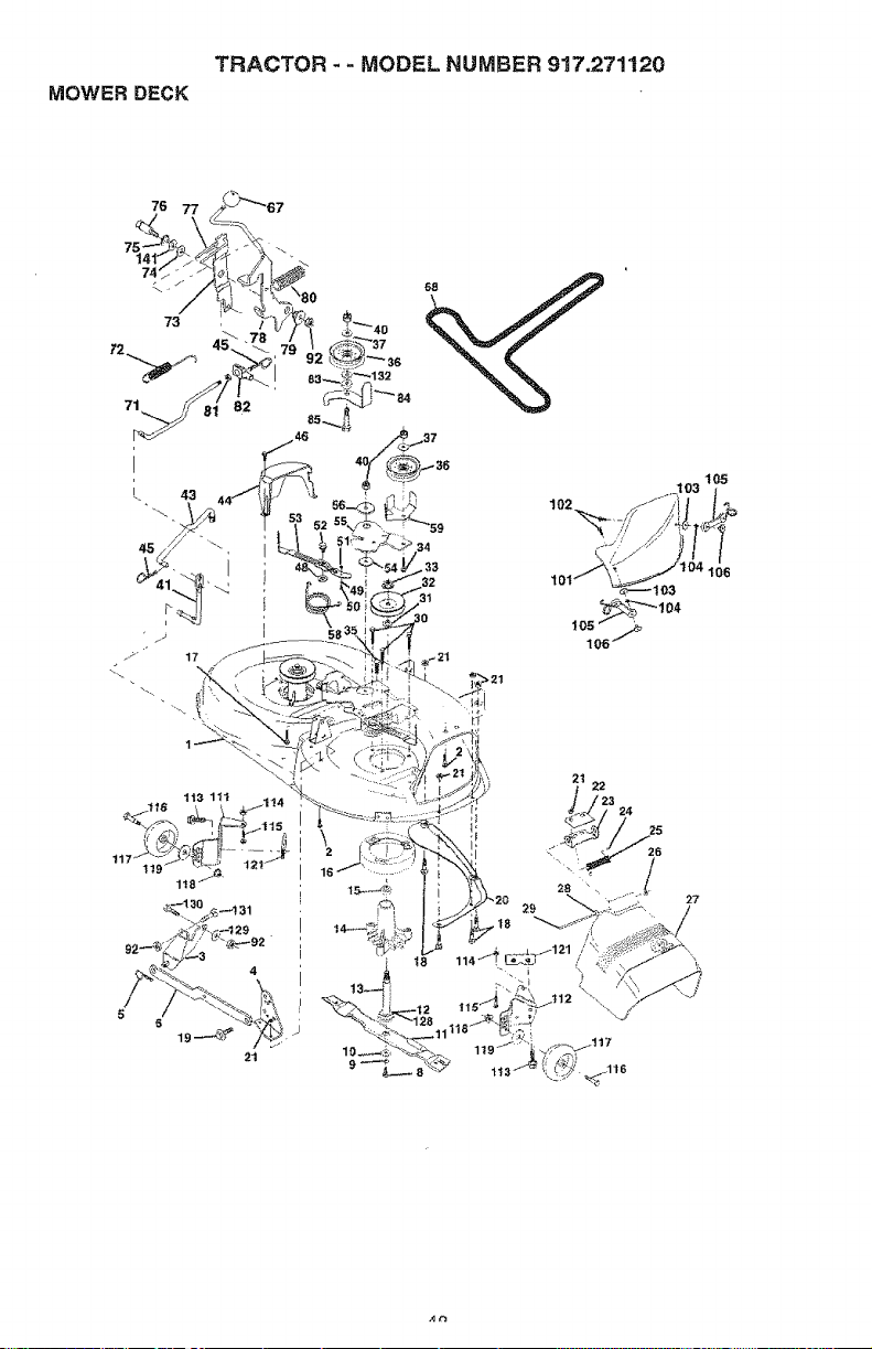
TRACTOR - - MODEL NUMBER 917.271120
MOWER DECK
>21
105
2t
22
24
25
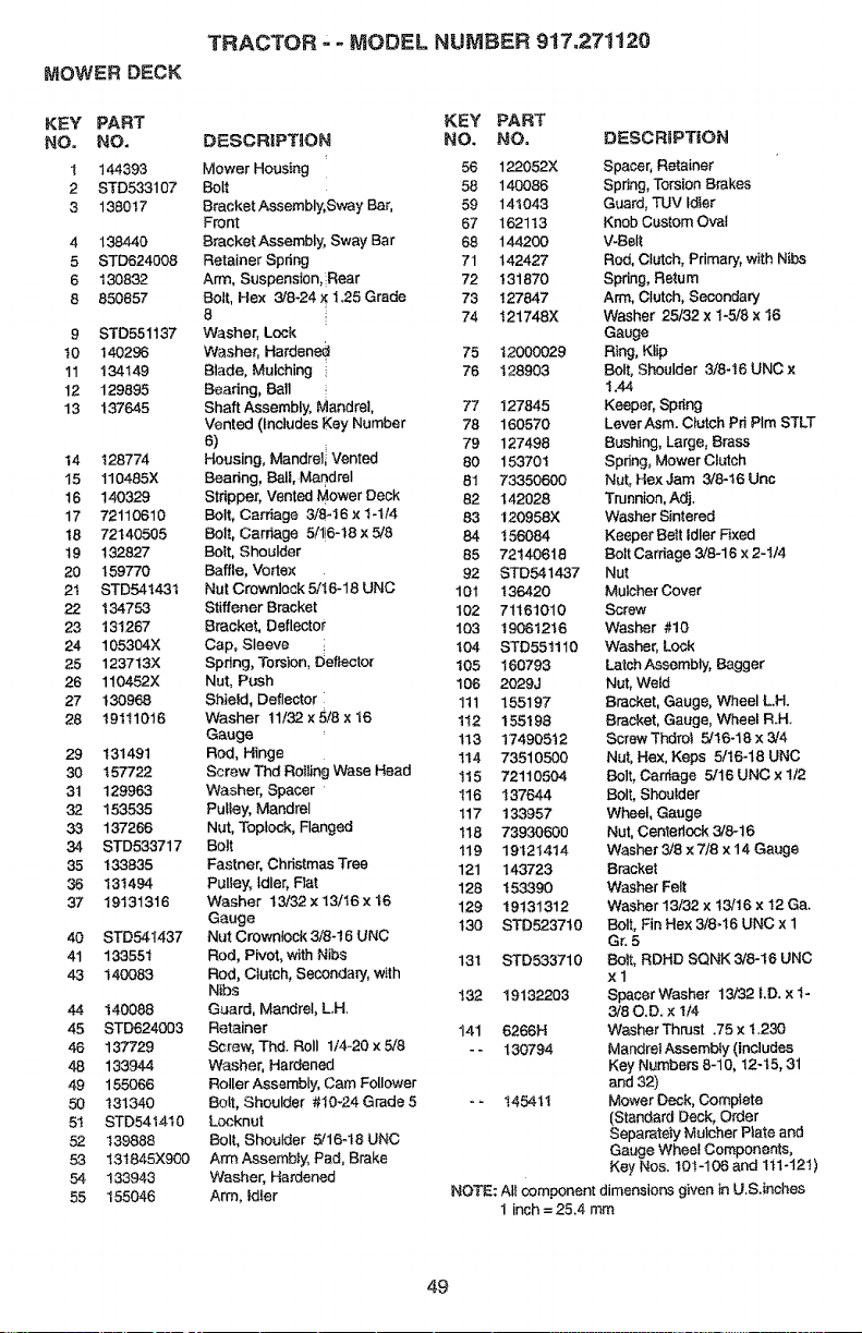
MOWER DECK
KEY PART
NO. NO,
1 144393
2 STD533107
3 138017
4 138440
5 STD624008
6 130832
8 850857
9 STD551137
t0 140296
11 134149
12 129895
13 137645
I4 128774
15 1104&SX
16 140329
17 72110610
18 72140505
19 132827
20 159770
2t STD54143t
22 134753
23 13t267
24 105304X
26 123713X
26 110452X
27 130968
28 19111016
29 131491
30 I57722
31 129963
32 153535
33 137266
34 STD533717
35 133835
36 131494
37 19131316
40 STD541437
41 133551
43 140083
44 140088
45 STD624003
45 137729
48 133944
49 155066
50 131340
5t STD5414t0
52 139888
53 t31845X900
54 133943
55 155046
TRACTOR - MODEL NUMBER 917,271120
DESCRIPTION
Mower Housing
Bolt
Bracket Assembly, Sway Bar,
Front
Bracket Assembly, Sway Bar
Retainer Spring
Arm, Suspension, Rear
Bolt, Hex 3/8-24 X 1.25 Grade
8
Washer, Lock
Washer, Hardened
Blade, Mulching
Beadng, Ball
Shaft Assembly, Mandrel,
Vented (Includes Key Number
6)
Housing, Mandrell Vented
Beadng, Ball, Mandrel
Stripper, Vented Mower Deck
Bolt, Carriage 3/8_16 x 1-t/4
Bolt, Cardage 5/1!6-t8 x 5/8
BoIt, Shoulder
Baffle, Vortex
Nut Crowniock 5/16-18 UNC
Stiffener Bracket
Bracket, Deflector
Cap, Sleeve :.
Spring, Torsion, Deflector
Nut, Push
Shield, Deflector i
Washer 11/32 × 5/6 x t6
Gauge
Rod, Hinge
Screw Thd Rolling Wase Head
Washer, Spacer
Pulley, Mandrel
Nut, Toptock, Flanged
Bolt
Fastner, Christmas Tree
Pulley, Idler, Fiat
Washer 13/32 x 13/t6 x t6
Gauge
Nut Crownlock 3/8-t6 UNC
Rod, Pivot, with Nibs
Rod, Clutch, Secondary, with
Nibs
Guard, Mandrel, LH.
Retainer
Screw, Thd. Roll 1/4-20 x5/8
Washer, Hardened
Roller Assembly, Cam Follower
Bolt, Shoulder #10-24 Grade 5
Locknut
Bolt, Shoulder 5/16-18 UNC
Arm AssembJy, Pad, Brake
Washer, Hardened
Arm, !alter
KEY PART
NO. NO. DESCRIPTIOI'4
56 122052X Spacer, Retainer
58 140086 Spring, Torsion Brakes
59 141043 Guard, TUV idler
67 1621 t3 Knob Custom Oval
68 144200 V-Belt
71 142427 Rod, Clutch, Primary, with Nibs
72 131870 Spdng, Retum
73 127847 Arm, Clutch, Secondary
74 121748X Washer 25/32 x 1-5/8 x 16
Gauge
75 12000029 Ring, KLip
76 t28903 Bolt, Shoulder 3/8-16 UNC x
1.44
77 127845 Keeper, Spdng
78 160570 Lever Asm. Clutch Pd PIm STLT
79 127498 Bushing, Large, Brass
80 15370t Spring, Mower Clutch
81 73350600 Nut, HexJam 3/8-16 Unc
82 142028 Trunnion, Adj.
83 120958X Washer Sintered
84 156084 Keeper Belt idler F_xed
85 72t406t8 Bolt Cardage 3/8-16 x 2-I/4
92 STD541437 Nut
101 136420 Mulcher Cover
102 71161010 Screw
103 19081216 Washer #10
t04 STD551110 Washer, Lock
105 160793 Latch Assembly, Bagger
106 2029J Nut, Weld
1t! 155197 Bracket, Gauge, Wheel LH.
1!2 155198 Bracket, Gauge, Wheel R.H.
113 17490512 Screw Thdrol 5/16-18 x 3/4
It4 73510500 Nut, He)(, Keps 5/16-18 UNC
It 5 72110504 Bolt, Carriage 5/t6 UNC x 112
116 137644 Bolt, Shoulder
117 133957 Wheel, Gauge
118 73930600 Nut, Centedeck 3/8-16
t19 19121414 Washer 3/8 x7/8 x 14 Gauge
121 143723 Bracket
128 I53390 Washer Felt
129 19131312 Washer 13/32 x t3/16 x 12 Ga.
t30 STD523710 Bolt, Fin Hex 3/8-16 UNC × 1
Gr. 5
13t STD533710 Bolt, RDHD SQNK 3/8-t6 UNC
x1
t32 19132203 Spacer Washer t3/32 !.D. x 1-
3/80.D. x 1/4
141 6266H Washer Thrust .75 x t.230
- - 130794 MandreI Assembty (Includes
Key Numbers 8-10, 12-15, 31
and 32)
° - 145411 Mower Deck, Complete
(Standard Deck, Order
Separately Mulcher Plate and
Gauge Wheel Components,
Key Nos. 10t-106 and ttl-121)
NOTE: All component dimensions given in U.S.inches
1 inch = 25,4 mm
49
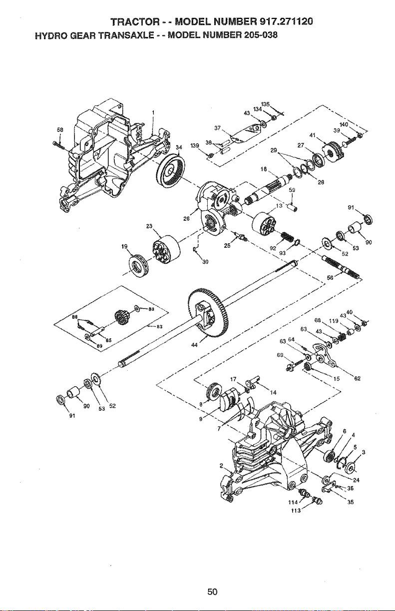
TRACTOR -- MODEL NUMBER 917.271120
HYDRO GEAR TRANSAXLE - - MODEL NUMBER 205-038
58
28
5£
91
5O
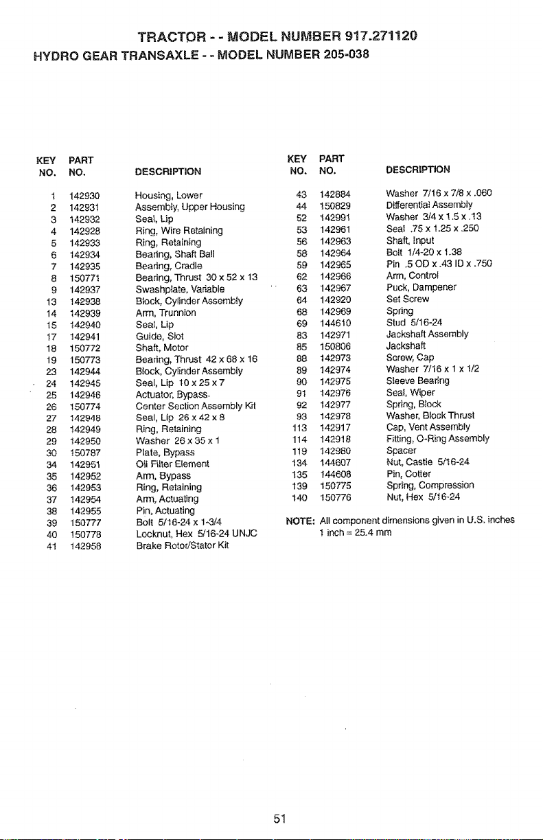
TRACTOR - - MODEL NUMBER 9!7,271120
HYDRO GEAR TRANSAXLE - - MODEL NUMBER 205-038
KEY PART KEY PART
NO. NO. DESCRIPTION NO, NO, DESCRIPTION
1 142930 Hot=sing, Lower 43 142884 Washer 7/16 x 7/8 x .060
2 142931 Assembly, Upper Housing 44 150829 Differential Assembly
3 142932 Seat, Lip 62 142991 Washer 3/4 x !.5 x .t3
4 142928 Ring, Wire Retaining 53 142961 Seat .75 x 1.25 x .250
5 142933 Ring, Retaining 56 142963 Shaft, _nput
6 142934 Bearing, Shaft Bail 58 142964 Bolt I/4-20 x 1.38
7 142935 Bearing, Cradle 59 142965 Pin .50b x .43 ID x .750
8 150771 8eadng, Thrust 30 x 52 x 13 62 142966 Arm, Control
9 142937 Swashp_ate, Variable ' 63 142967 Puck, Dampener
13 142938 Brock, Cylinder Assembly 64 142920 Set Screw
14 142939 Arm, Trunnion 68 142969 Spring
15 142940 Seat, Lip 69 144610 Stud 5/16-24
17 142941 Guide, Stot 83 142971 JackshaftAssembly
18 150772 Shaft, Motor 85 150806 Jackshaft
19 150773 Bearing, Thrust 42 x 68 x 16 88 142973 Screw, Cap
23 142944 B{ock, CylinderAssembly 89 142974 Washer 7/16 × 1 x !/2
24 142945 Seal, Lip 10 x 25 x 7 90 142975 Sleeve Beadng
25 142946 Actuator, Bypass_ 9t 142976 Sea_, Wiper
26 150774 Center Section Assembly Kit 92 142977 Spring, Brock
27 142948 Seal, Lip 26 x 42 x 8 93 142978 Washer, Block Thrust
28 142949 Ring, Retaining 113 142917 Cap, Vent Assembly
29 142950 Washer 26 x 35x I 114 142918 Fitting, O_RingAssembly
30 t50787 Plate, Bypass 119 142980 Spacer
34 142951 0it FilterEteme_t t34 144607 Nut, Castle 5/t6-24
35 142952 Arm, Bypass t35 144608 Pin, Cotter
36 142953 Ring, Retaining 139 150775 Spring, Compression
37 142954 Arm, Actuating 140 150776 Nut, He× 5/16424
38 142955 Pin, Actuating
39 150777 Bolt 5/t6-24 x 1-3/4 NOTE: All component dimensions given in U.S. inches
40 150778 Locknut, Hex 5/16-24 UNJC 1 inch = 25.4 mm
41 !42958 Brake RotoriStator Kit
51
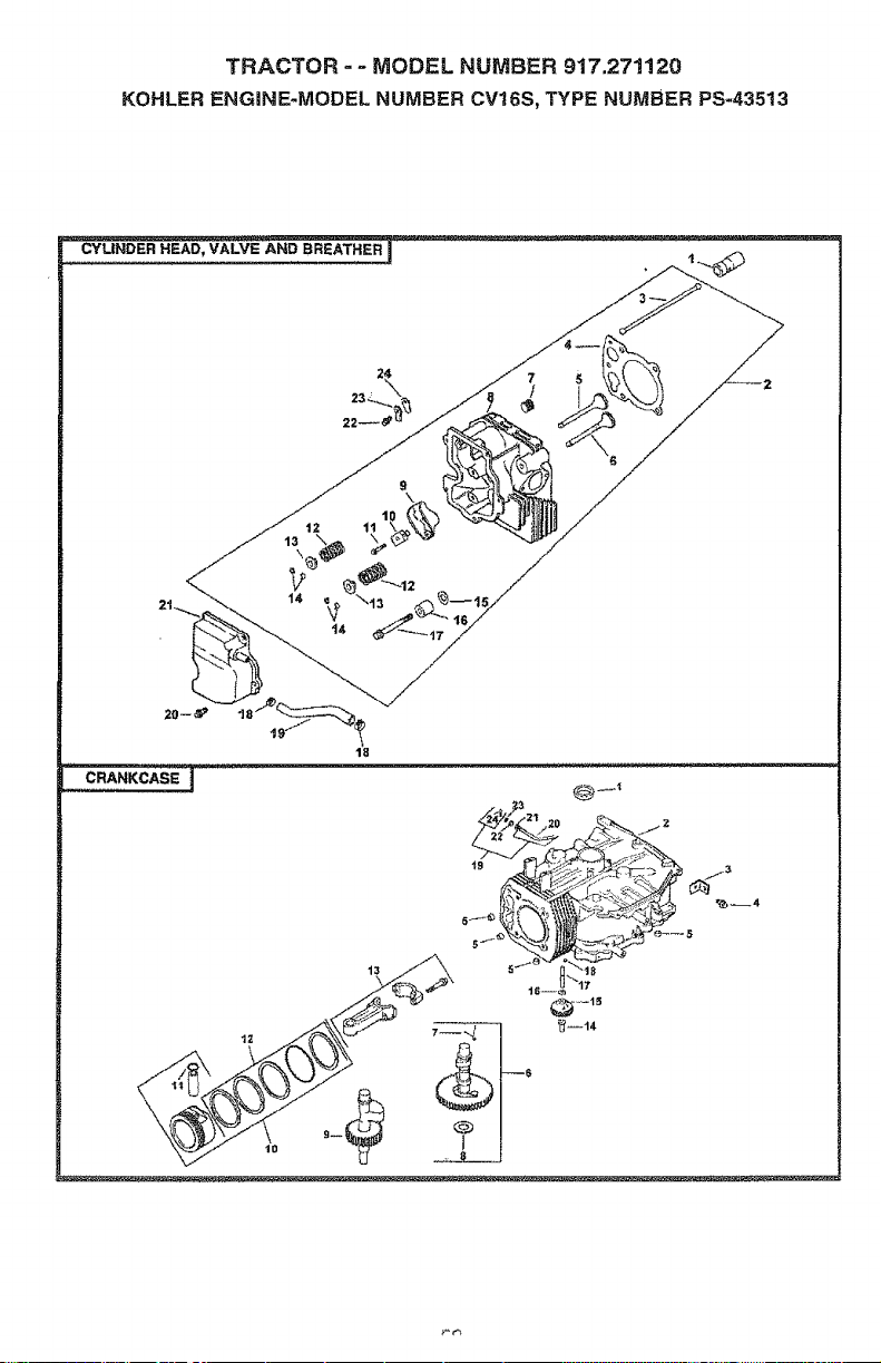
TRACTOR - - MODEL NUMBER 917.271120
KOHLER ENGINE-MODEL NUMBER CV16S, TYPE NUMBER PS-435t3
9
t4
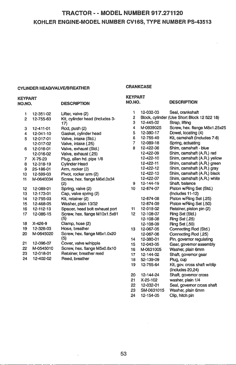
TRACTOR - - MODEL NUMBER 917.271120
KOHLER ENGINE-MODEL NUMBER CV16S, TYPE NUMBER PS-43513
CYLINDER HEADiVALVFJBREATHER
CRANKCASE
KEYPART KEYPART
NO.NO, DESCRIPTION NO.NO. DESCRiPTiON
1 12-351-02 Lifter, valve (2) I t2-032-03 Seal, crankshaft
2 t2-755-63 Kit, cylinder head (includes 3- 2 Block, cylinder (Use Shor_ Block 12 522 18)
17) 3 12"445-02 Strap, Iifting
3 t2-411-01 Rod, push (2) 4 M-0839025 Screw, hax. flange M8×1.25:<25
4 12-04t-t0 Gasket, cylinder head 5 12_380-17 Dowel, locating (4)
5 t2-017-01 Valve, intake (Std.) 6 12_755.49 Kit, camshaft (Includes 7-6)
12-017-02 Valve, intake (.25) 7 12-089-!8 Spdng, actuating
6 !2-0t6-01 Valve, exhaust (Std.) 8 t2-422-08 Shim, camshaft - blue
t2-016.02 Valve, exhaust (.25) 12.422-09 Shim, camshaft (A.R.) red
7 X-75-23 PIug, allen hd. pipe t/8 t2-422-10 Shim, camshaft (A.R.) yellow
8 !2-318-19 Cylinder Head t2.422-11 Shim, camshaft (A.R.) green
9 25-186-0t Arm, rocker (2) t2-422-12 Shim, camshaft (A.R.) gray
10 t2-599-03 Pivot, rocker arm (2) 12-422-13 Shim, camshaft (A.R.) black
I1 M-0640034 Screw, hex. flange M6xt.0x54 12.422-07 Shim, camshaft (A.R.) white
(2) 9 t2_144-19 Shaft, bafance
12 12-089-0t Spdng, vane (2) t0 12-874-07 Piston w/Ring Set (Std.)
13 t2-173"0! Cap, valve spring (2) (Includes t1-12)
14 12-755-03 Kit, retainer (2) 12-674-08 Piston w]Rlog Set (`25)
15 12_468-05 Washer, plain t 3/32 12-674-09 Piston wiRing Set (.50)
16 12-1t2-13 Spacer, head bolt exhaust port tl 12-018-02 Retainer, piston pin (2)
17 I2-O86-t5 Screw, hex. flange M10x!.5x81 12 12-108-07 Ring Set (Std.)
(5) 12-t08-08 Ring Set (,25)
18 X_.26-6 Ctamp, hose (2) t2-t08-09 Ring Set (.50)
19 t2-326-03 Hose, breather 13 12-067-05 Connecting Rod (Std.)
20 M-0645020 Screw, hex. flange M6x1.0x20 12-067-08 Connecting Rod (.25)
(5) 14 12-380-0t Pin, governor regulating
21 12-096-07 Cover, valve w/nipple 15 t2-043-05 Gear, governor assembly
22 M-0545010 Screw, hex. flange MSx0.8xl0 16 M"063t005 Washer, plain 6mm
23 t2-018-01 Retainer, breather reed 17 12-144-02 Shaft, goverr_r gear
24 12.402-02 Reed, breather t8 52-139-09 Plug, cup
19 12-755-64 Kff, gov. cross shaft w/clip
(Includes 20,24)
20 12-144-24 Shaft, governor cross
21 X-25-102 washer, plain 1/4
22 12-032-01 Seal, governor cross shaft
23 SM-06310t5 Washer, plain 6ram
24 12-t54-05 Clip, hitch pin
53
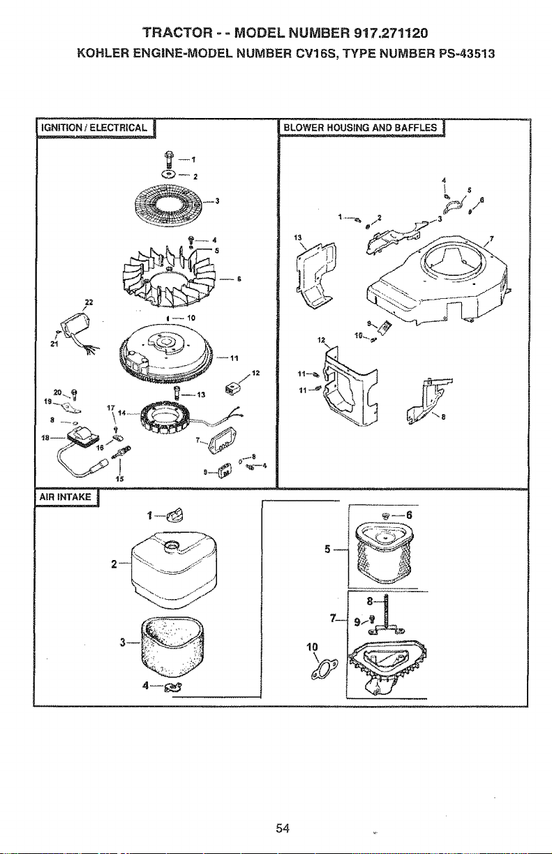
TRACTOR - - MODEL NUMBER 917.271120
KOHLER ENGINE-MODEL NUMBER CV16S, TYPE NUMBSR PS-43513
BLOWER HOUSING AND BAFFLES !
13
10
54
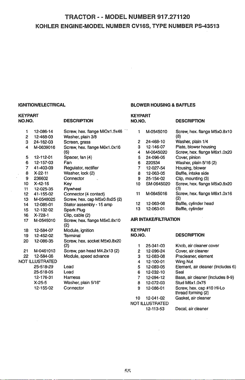
TRACTOR - - MODEL NUMBER 917.271120
KOHLER ENGINE-MODEL NUMBER CV16S, TYPE NUMBER PS-43513
IGNITION/ELECTRICAL
KEYPART
NO.NO. DESCRIPTION
I 12-.086-t4
2 12-468-03
3 24-t62-03
4 M-0639016
5 i2q12`01
6 I2-157-03
7 4%403`09
8 X-22-1t
9 236602
I0 X-42-t5
11 t2-025-35
t2 41q55`02
I3 M-O548025
t4 12`085`01
!5 12-t32`02
16 X'728-1
17 M`0545010
18 12"584207
19 t2-452`02
20 12-086-35
21 M-04610t3
22 t2-584-06
NOT ILLUSTRATED
25-5t8-29
25-518-05
12"176-3t
X-25-5
12-155-02
BLOWER HOUSING & BAFFLES
KEYPART
NO.NO. DESCRIPTION
Screw, he×. flange MIOx1.Sx46 " t
Washer, plain 3/8
Screen, grass 2
Screw, hex. f_ange M6x1.0x16 3
(6) 4
Spacer, fan (4) 8
Fan 6
Regulator, rectifier 7
Washer, lock (2) 8
Connector 9
Key 10
F:lywheel
Connector (4 contact) tl
Screw, hex. cap M5x0.8x25 (2)
Stator assembly * t 5 amp t 2
Spark Plug 13
Clip, cable (2)
Screw, hex. flange MSx0.exl0
(2)
Module, ignition KEYPART
Terminal NO.NO.
Screw, hex, socket M5x0.8x20
{2)
Screw, pan head M4,2x13 (2)
Module. speed advance
Lead
Lead
Harness
Washer, plain 5/t6"
Connector
M`05450t0
24-468-10
12-t46`07
M`0645020
24-096435
220534
12`027-54
12-063-05
25-t54`02
SM`0545020
M-0645016
t2-063-08
12`063`01
Screw, hex. flange MSx0.8×10
(8)
Washer, plain I/4
Plate, blower housing
Screw, hex. flange M6xt.0x20
Cover, pinion
Washer, p_ain 5/16 (2)
Housing, blower
Baffle, intake side
Clip, mounting (3)
Screw, hex. flange M5x0.8x20
(3)
Screw, hex. ftange M6x1.0x16
(2)
Baffle, cylinder head
Baffle, cylinder
AiR INTAKE/FILTRATION
DESCRIPTION
! 25-341`03
2 t2-096-24
3 12-083-08
4 12-100`01
5 12-083`05
6 12`032-10
7 12`094-t2
8 !2-072433
9 12-086-01
t0 12-041 `02
NOT ILLUSTRATED
t2qt3-53
Knob. eir cleaner cover
Cover, air cleaner
Precleaner, element
Wing Nut
Element, air cleaner (includes 6)
Seal
Base, air cleaner (inCludes 8-9)
Stud M6x 1.0x75
Screw, he×_cap #10 Hi-Lo
thread fom_ng (2)
Gasket, air cleaner
Decal, air cleaner
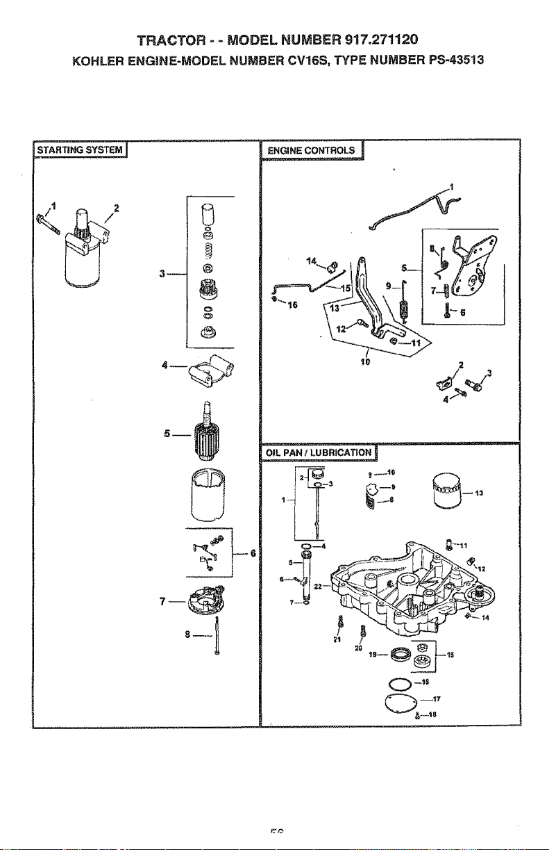
TRACTOR - - MODEL NUMBER 9!7,27t120
KOHLER ENGINE-MODEL NUMBER CV16S, TYPE NUMBER PS-43513
STARTING SYSTE_
3_
@
°-!
ENGINE CONTROLS ]
Io 2
4 f-,,Q
27_ _ _t0
13
2G 19-- 15
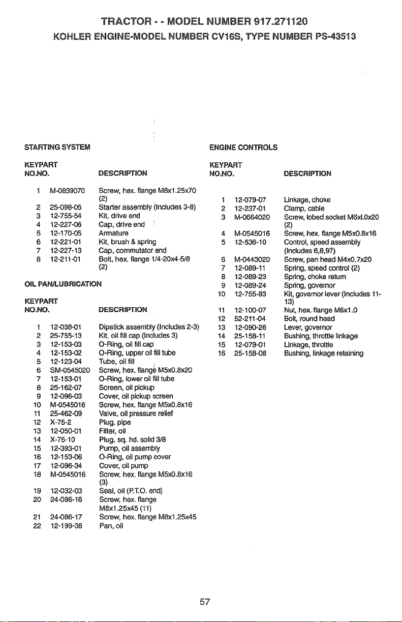
TRACTOR o - MODEL NUMBER 917o27!120
KOHLER ENGNNE-MODSL NUMBER CV16S_ TYPE NUMBER PS-43513
STARTING SYSTEM
KEYPART
NO.NO,
ENGINE CONTROLS
KEYPART
DESCBIPTION NO,NO, DESCRiPTiON
2
3
4
5
6
7
8
M_0839070
2,5-098-05
t2-755_54
12-227-06
t 2- t 70-05
12-221-01
12-227-t 3
12-211-01
Screw, hex. flange M8x1.25x70
(2)
Starter assembFy (Includes 3*8)
Kit, drive end
Cap, drive end
Armature
Kit, brush & spring
Cap, commutator end
Bolt, hex. flange 1/4-20x4-5f8
(2)
OIL PAI',_,.UBRICATION
DESCRIPTION
1
2
3
4
5
6
7
8
9
t0
!1
t2
t3
I4
t5
t6
17
t8
t9
2O
21
22
12-038-01
25-755-t3
12-t53-03
12-153`02
12-123-04
SM-0545020
12-153`01
25-t 62-07
12-096-03
M`05450t6
25-462`09
X-75-2
t2`050`0t
X-75-10
t2-393`0t
t2-153-06
12-096-3,4
M`0545016
!2-032`03
24`086-16
24-086-t7
12-t 99-38
Dipstick assembly (includes 2-3)
Kit, oil fill cap (tnc!udes 3)
O-Ring, elf filt cap
O-Ring, upper oil fill tube
Tube, oil fill
Screw, hex. flangeM5x0.Sx20
O-Ring, lower oit fitl tube
Screen, oil pickup
Cover, oiI pickup screen
Screw, hex. flange M5x0.8xt6
Valve, oi] pressure relief
Plug,pipe
Fitter, oil
Ptug, sq. hal. solid 318
Pump, oil assembly
O-Ring, oil pump cover
Cover. oil pump
Screw, hex, flange M5xO.Sx16
(3)
Seal, oil (RT.O. end)
Screw, hex, flange
M8xl.25x45 (tl)
Screw, hex. flange M8x1.25x45
Pan, of!
1 12-079-07
2 t2-237`01
3 M`0664020
4 M-0545016
5 12-536-10
6 M-0443020
7 12-089_11
8 12-089-23
9 t 2`089_24
t0 t2-755-83
11 12-100-07
t2 52-211`04
13 12-090-26
14 25-t 58-11
15 12-079-0t
16 25-t58-08
Unkage, choke
Ciamp, cabfe
Screw, tobed socket M6xt.Ox20
(2)
Screw, hex. flange M5x0.8×t6
Control, speed assembly
(Includes 6,8,9?)
Screw, pan head M4x0.Tx20
Spnng, speed controt (2)
Spdng, choke return
Spring, governor
Kii, governor Iever (Includes tl-
13)
Nut, he×. fIange M6xt.O
Bolt, round head
Lever, governor
Bushing, throttle linkage
Unkage, throttle
Bushing, linkage retaining
57

58

SUGGESTED GUIDE FOR SiGHTiNG SLOPES FOR SAFE OPERATION
ONLY RIDE UP AND DOWN HILL,
NOT ACROSS HILL
SIGHT AND HOLD THIS LEVEL WITH
SKY LINE OR TREE.
15 ° MAX.
Operate your Tractor up and down the face of slopes (not
greater than 15°), never across the face. Make turns gradu-
agy to prevent tipping or loss of control. Exercise extreme
caution when changing direction on slopes,
For the repair or replacement parts you need
delivered directly to your home
Call 7 am - 7 pm, 7 days a week
1-800-356oPART
(1..800-366-7278)
Para ordenar piezas con entrega a
domiciiio - 1-800_659-7084
For in-house major brand repair service
Call 24 hours a day, 7 days a week
1oSO0=4=REPAIR
(1-800-473W274)
Para p_dir servicio de reparaci6n a
domiciHo - 1-800o678o5811
For the location of a Sears Parts and
Repair Center in your area
Call 24 hours a day, 7 days a week
1-800=488=1222
For information on purchasing a Sears
Maintenance Agreement or to inquire
about an existing Agreement
Catl 9 am - 5 pro, Monday-Saturday
1=800=827=6655
When requesting service or ordering
parts, amwaysprovide the following
information:
Product Type - Part Number
Moden Number - Part Description
America's Repair Specialists
163488 Revo I 12,04o97 RD Printed in


