Loading ...
- 2 -
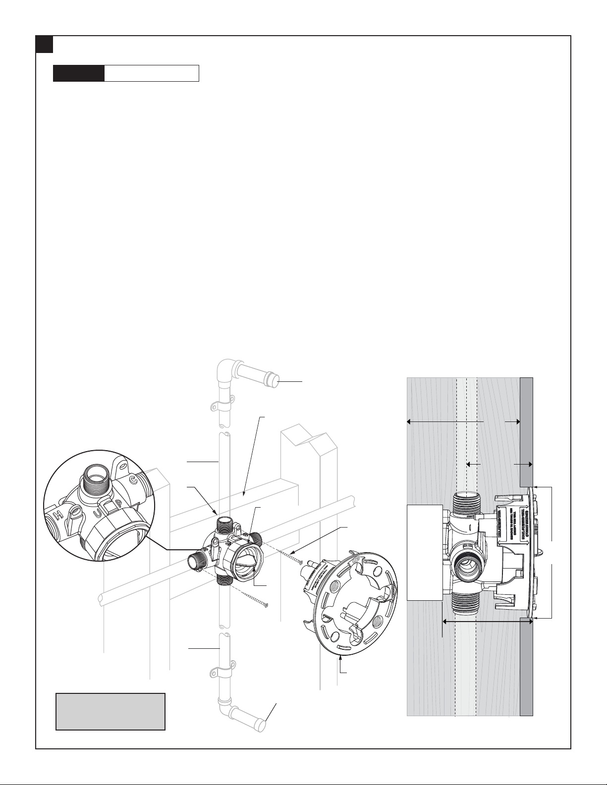
n See Roughing-in diagram before starting.
n Remove the PLASTER GUARD (8) for proper installation.
n Mount VALVE BODY to cross brace (2" X 4") with-in wall. Use wood screws to secure VALVE BODY to brace.
n Connect HOT and COLD water supplies per connection method of selected valve.
n Connect RISER PIPE (1) to VALVE BODY (2) top outlet marked “UP”.
n Connect TUB FILLER PIPE (3) to bottom outlet.
n Cap off shower pipe (4) and tub ller pipe (5).
n With TEST CAP (7) in place and BONNET NUT (6) installed securely, turn on water supplies and check for leaks.
n Remove cap 4 to ush the water through shower pipe.
n Remove cap 5 to ush the water through tub ller pipe.
n Install PLASTER GUARD (8) back onto the valve. Only remove PLASTER GUARD (8) when ready to install trim Kit.
n Finished wall should allow for a 4" diameter opening (Use PLASTER GUARD for guidance)
STANDARD WALL INSTALLATION
1
M965906 (5/18)
CAUTION
Turn off hot and cold water
supplies before beginning.
COLD
1
2
4
3
5
WOOD
SCREWS
CROSS BRACE
HOT
7
6
8
NOTE: Cross flow can occur, if hot and cold pressures are not equal during testing.
For this situation purchase FLUSH PLUG (M954334) separately. See section 3 for test procedures.
CAUTION: After valve installation, inspect the VALVE BODY for any debris. It can damage Pressure Balance
Valve cartridge.
NOTE: For back to back installation, follow steps mentioned above. Reversal of Hot/Cold water supplies is
accomplished by rotating cartridge (supplied with trim) 180° during installation.
4"
(101 mm)
2 x 4
Cross
Brace
7/8" TO 2"
(22 mm to
50 mm)
3-1/2"
(100 mm)
2-3/4" MAX.
(69 mm)
1-3/4" MIN.
(45 mm)
SIDE VIEW
NOTE: TO AVOID SHOWER RISE OR
OTHER RELATED ISSUES, DO NOT
USE PEX CONNECTIONS ON ANY OF
THE OUTLETS.
Loading ...
Loading ...
Loading ...