

INSTALLATION GUIDE
Before you install this product, read this guide completely and
make sure you understand all of the content.
ENGLISH
Hisense Laser TV Screen
ES-A2249Z2
1
be moved.
Product Description
Dust, dirt and scratches on the screen will affect how images appear. Follow the instructions below to properly maintain the
screen.
1) The screen surface has a horizontal structure.
DO NOT
wipe the screen up and down or in a circular motion.
Wipe from left to right only.
2) Clean the dust on the screen surface with a soft brush or microfiber cloth. A rough towel or cloth might damage the surface.
3) Gently wipe the screen with a moistened microfiber cloth with mild soap diluted in water.
IMPORTANT:
Take heed to the following precautions at all times in order to avoid damaging the
screen. It is not covered under warranty.
• Don’t
touch
the screen material to avoid leaving fingerprints.
Use gloves when handling the material.
• Don’t
scratch
the material, as it will leave permanent markings on the screen’s surface.
• Don’t
point
to the screen material with a fingertip or other sharp objects to prevent damage to the material.
• Don’t use acetone, benzene, alcohol and any other organic solvents to clean the screen material. Using such chemicals
will permanently damage the screen.
Maintaining the Screen
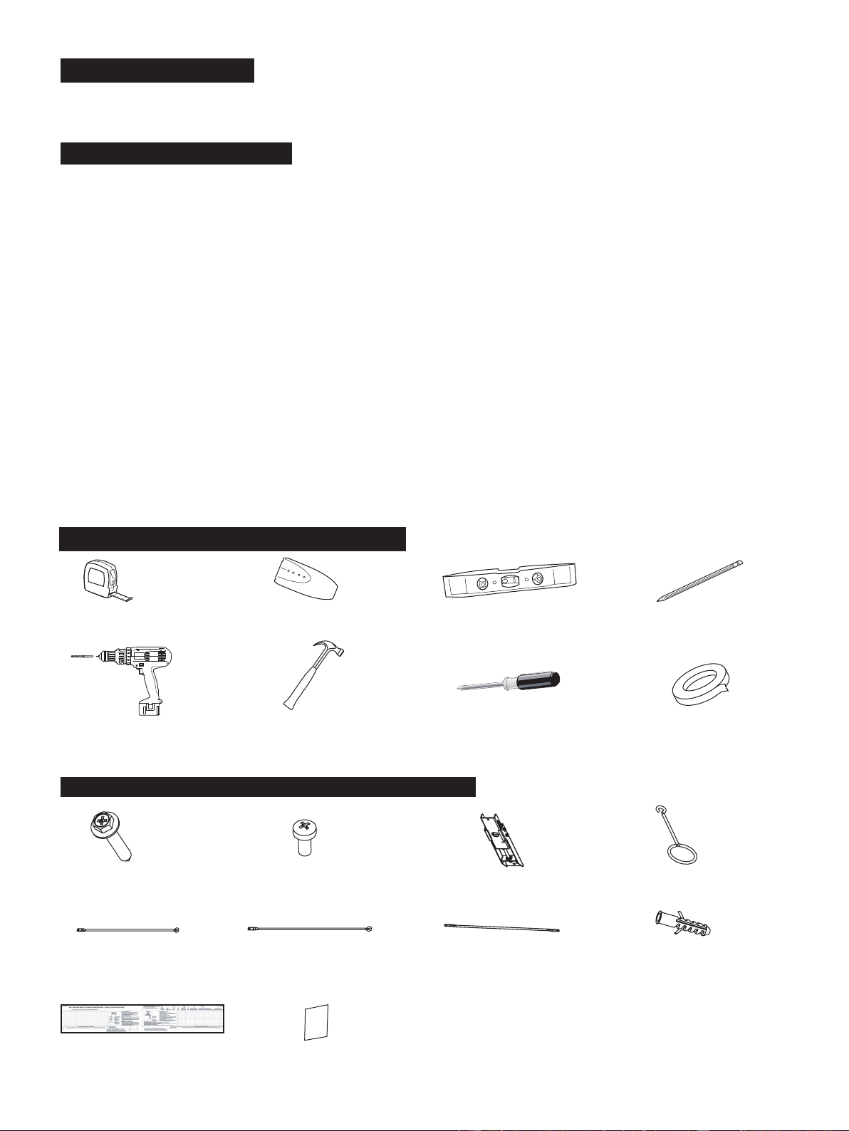
Required Tools to Install the Screen
Tape measure Stud nder Level Pencil
Screwdriver with 5/16"(8mm)
drill bit for wood stud
Hammer for concrete Phillips screwdriver Tape
anchors
Hardware and Parts List for Screen Mounts
ST5.5x70 Screws (x4) M3x6 Screws (x8)
Drill bolt 8 x 60,
Polyamide 6 (PA6)
(x4)
Bracket wands (x2)
460mm
Bracket wands (x2)
500mm
Handle (x2)
Hanging component (x2)
Velcro strips (x4)
Paper template (x1)
Bracket wands (x2)
269mm
The Hisense Laser TV Display Screen has a bezel trim and is designed to be used in rooms where the ceiling light can not
2
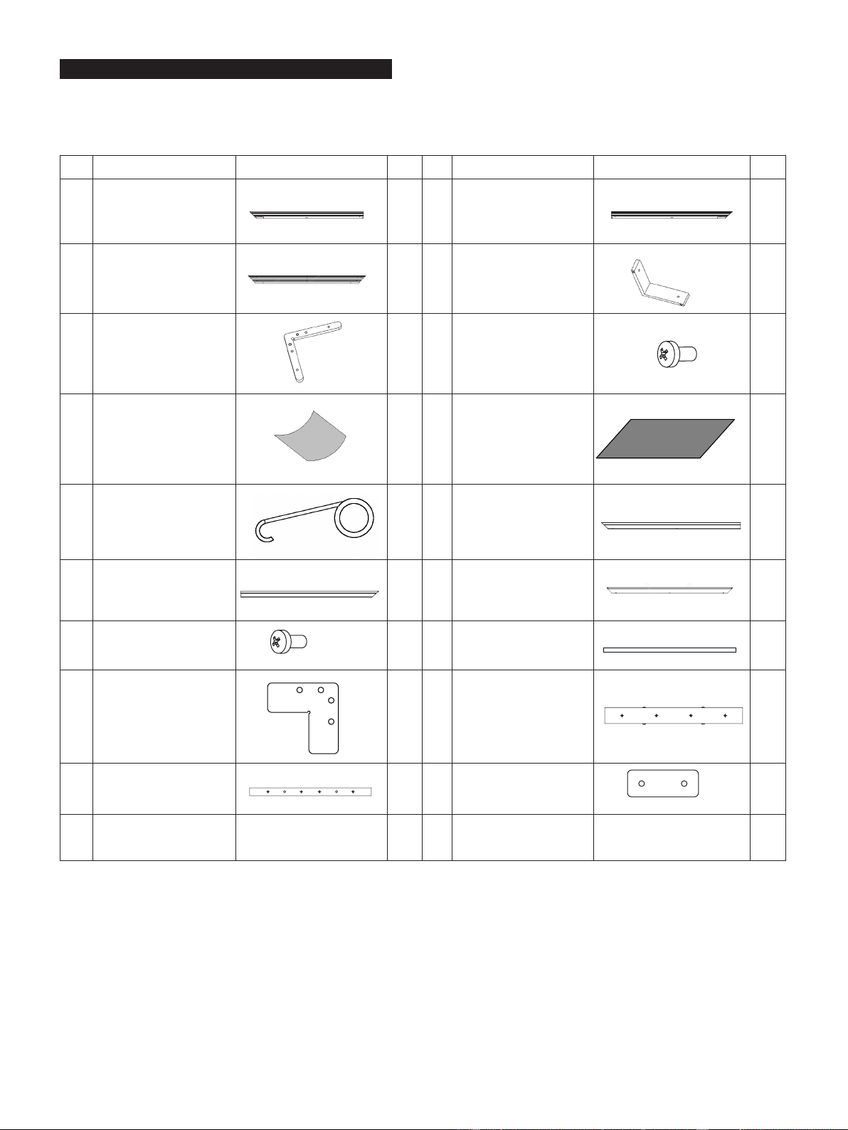
Hardware and Parts List for Screen
Make sure you have all of the parts shown below before you begin the installation procedure.
Product optimization and upgrade might cause differences of components, which are for reference only. Please refer to the
actual product.
No. Name Picture Qty. No. Name Picture Qty.
A1
Long Inner Frame
(17 springs included)
2 A2 Long Inner Frame
2
B Short Inner Frame
2 C L Corner Piece
4
D L Elbow Joints
4 E M4x6 Screws
40
F
Cloth Liner
for Assembly
1 H Reflecting Screen
1
K Spring Hook
2 L1 Long Outer Frame
2
L2 Long Outer Frame
2 M Short Outer Frame
2
N M3x7 Screws
44 O Vertical Beam
1
P L Corner Fitting
4 Q Connector 2
R Connector
2 S Connector
2
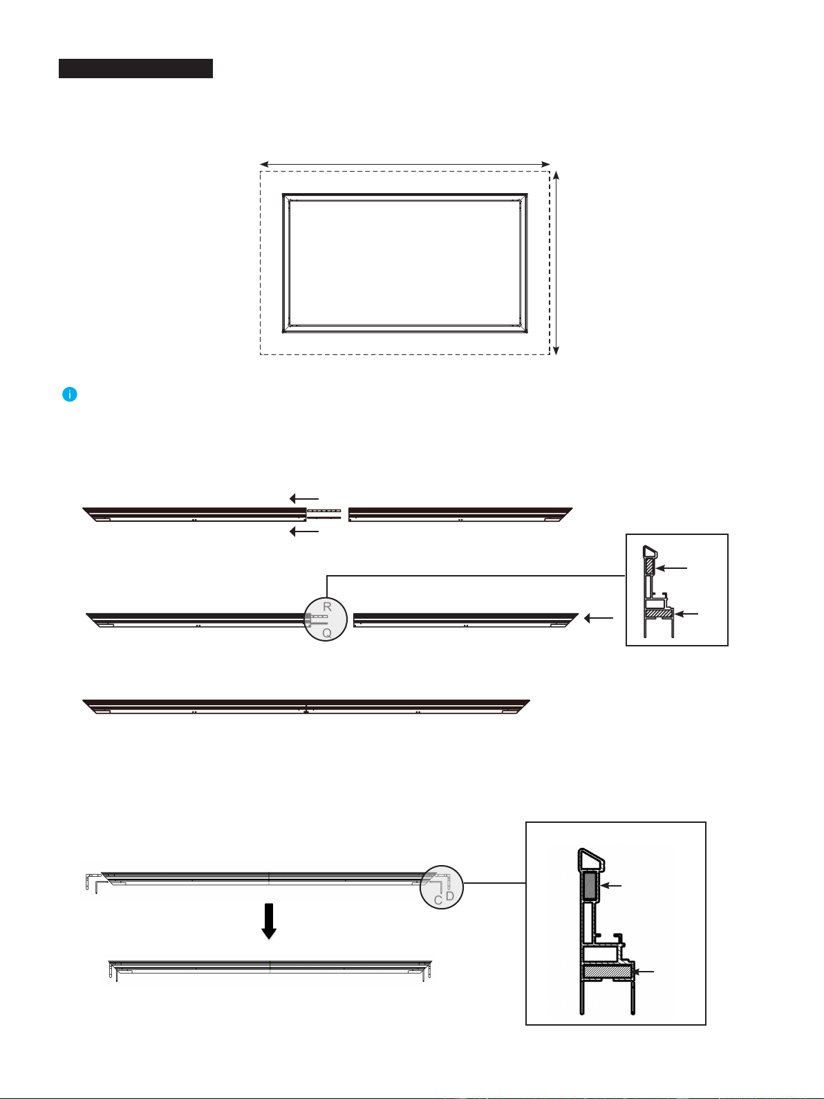
3
Place the
Cloth liner (F)
sponge on clean area on the ground to assemble the screen.
1. Connect
Long Inner Frame (17 springs included) (A1)
and
Long Inner Frame (A2)
with
Connector (Q)
and
Connector
(R)
to an integrated long inner frame, tighten
M4x6 Screws (E)
to secure it. The connecting procedures are as follows:
2.
Insert the
L Corner Piece (C)
, and then insert
L
Elbow Joint (D)
(front side is up) into each end of the
Long Inner Frame
(A1 , A2)
as shown below.
A2
D
D
D
C
D
D
C
C
C
C
Frame Assembly
Note:
The installation space should be at least 3.5m x 2.5m ( 137.8 inches x 98.43 inches).
≥ 3.5m (137.8 inches)
≥2.5m (98.43 inches)
A1
A2
A1
1) Use
M4x6 Screws (E)
to connect
Connector (Q)
and
Connector (R)
with
Long Inner Frame (17 springs included) (A1)
.
2) Insert
Connector (Q)
and
Connector (R)
to
Long Inner Frame (A2)
.
A1
R
Q
A2
A1 A2
R
Q
3) Use
M4x6 Screws (E)
to fix
Connector (Q)
and
Connector (R)
with
Long Inner Frame (A2)
.
A1
A2
Tips:
Fastening methods of screws refer to step 4.
R
Q
Prole
Prole
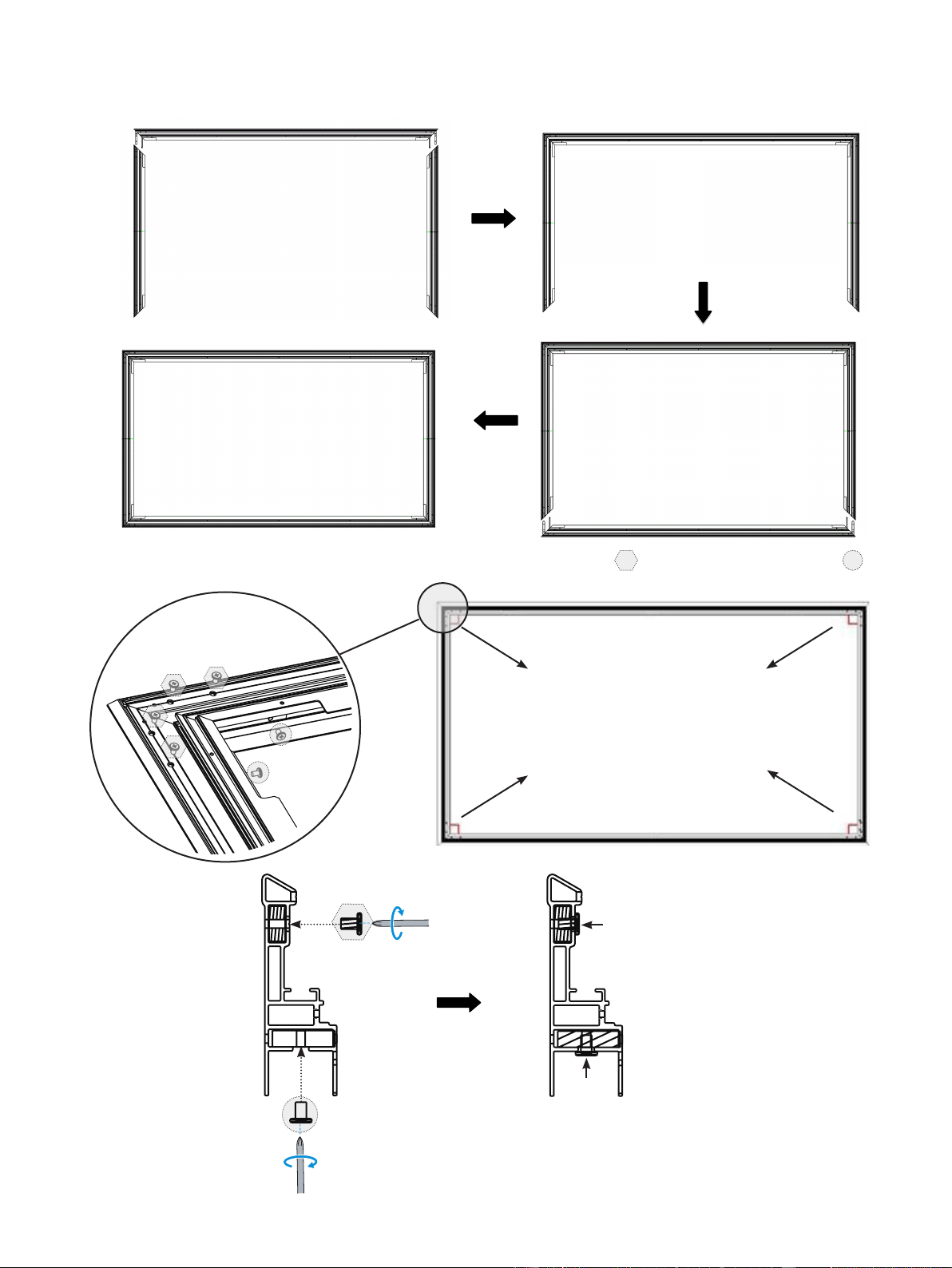
4
3. Insert the two
Short Inner Frames (B)
into the
L Corner Piece (C)
and
L Elbow Joint (D)
as shown in the diagram below.
4.
Fasten the four angles with the
M4x6 Screws (E)
. First fasten screws marked by , then fasten screws marked by in
the following figure.
A1
D
C
B B
D
C
A2
Make sure all four corners are
properly in place to form a
perfect square.
M4x6 Screw (E)
M4x6 Screw (E)
E
E
①
②
5
A1 A2
M3x7 Screw (N)
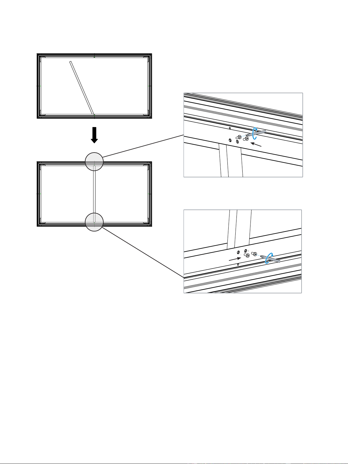
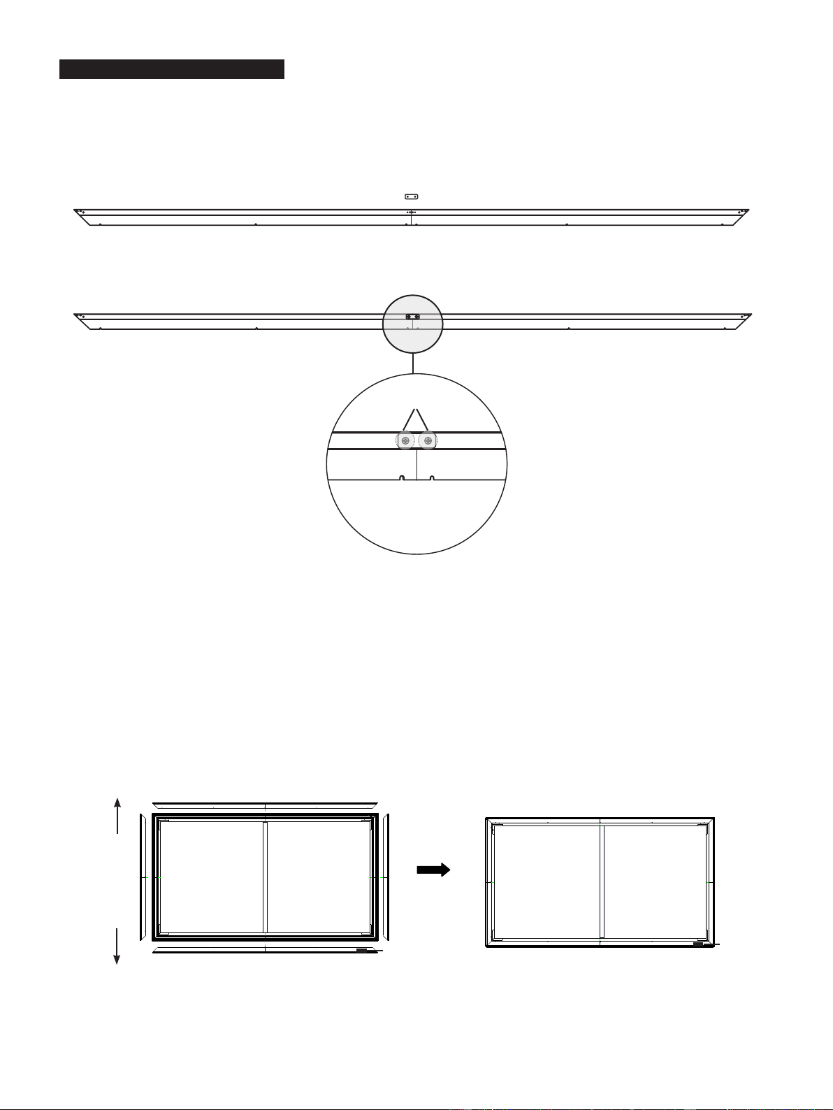
5. Mount the Vertical Beam (O) to support frames, ensure that the vertical beam is at the joint of
Long Inner Frame (17
springs included) (A1)
and
Long Inner Frame (A2)
and fasten with four M3x7 Screws (N).
M3x7 Screw (N)
6
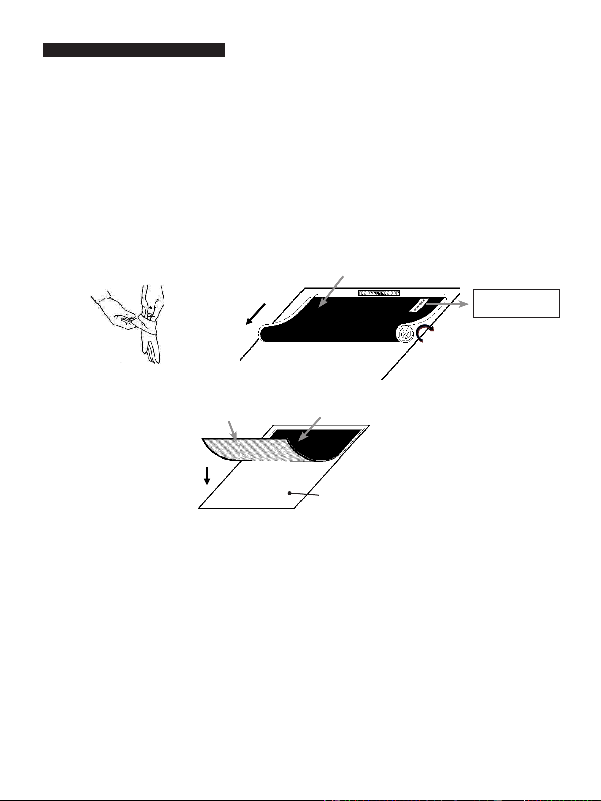
Please read this important note before proceeding with the installation process of the material:
Before handling the Reflecting Screen (H), put on the supplied pair of White Gloves (
Included in the
Laser T
V package,
please see Laser TV
cleaning kit ) to avoid leaving fingerprint marks, dust or oil from your hands on the surface of
the material (Figure 1). The Reflecting Screen (H) is very delicate and should be handled with extreme care. Do not
allow the material to fold or bend. Failure to follow instructions will result in permanent damage to the screen material,
which is not covered by warranty.
1.
Remove the
Reflecting Screen (H)
from the packaging tube and set it gently on a clean surface.
Tip: Carefully put a small flat weighted object at the edge to prevent it from moving out of place.
Please keep the front of the material face down.
2. It is strongly recommended for two people to unroll the material to prevent the screen from bending or rolling unevenly.
Each person should hold one end of the roll and slowly unroll the screen in a clockwise direction (Figure 2).
Tip: Check the
DOWNSIDE
label on the material.
3. Lay the material completely flat with the front facing down on a clean surface in a horizontal position (Figure 3)
.
Back side of material
Front side of
material
Figure 3
Screen on a clean cloth
in a horizontal position
DOWNSIDE
Figure 2
Back side of material
Figure 1
Screen Material Installation
7
4. Carefully and gently place the assembled frame on top of the screen material. Align the screen material corner with the
corner of assembled frame as the diagram below. In order to avoid puncturing the material, do not allow the angled edge of
the frame to come in direct contact with the screen.
5. With one end of the springs connected securely inside the groove of the frame, use the
Spring Hook (K)
to attach springs
to the holes located on the outer edge of the screen material. One hole on the horizontal outer edge matches one spring.
1) Attach the four corners first. Two people should use the
Spring Hook (K)
to attach springs to holes located on the outer
edge of the screen material in the order of 1-1→2-2→3-3→4-4, then 5-5→6-6→7-7→8-8.
Tip:
Each side will have one more spring for standby application.
Tip: Make sure the back of the screen material is facing
up as shown in this gure.
12
6
5
8
2 3 4
8
7
5
6
4
3
1
7
Step
①
Step
②
Step
③
Step
④
Align the corner
Top
Down
8
Tip:
The screen material is in the best position when the outer edge just covers
M4x6 Screws (E)
labeled above.
2)
After you’ve installed the corner of the material, assemble the spring in the order
①
→
②
shown below.
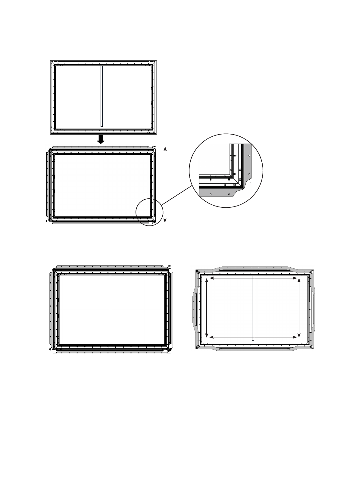
3) When finishing the steps above, make the screen to stand up and check if the screen material is stretched out of the frame.
If it is, then release the spring and readjust the screen material to make sure it is not be stretched out of the frame and the
four sides are parallel
to the four sides of the frame.
①
①
①
①
②
②
②
②
②
②
②
②
Stretch the screen material in the
direction of the arrowhead.
Use the
Spring Hook (K)
to attach
springs to holes located on both
horizontal and vertical outer edge of
the screen material.
Repeat until all of the springs are
installed.
M4x6 Screws (E)
9
Outer Frame Installation
1. Connect
Long Outer Frame
(L1)
and
Long Outer Frame
(L2)
with
Connector (S)
to an integrated long outer frame,
tighten
M3x7 Screws (N)
to secure it.
2. Place the outer frame along the four edges of the screen material corner, ensure that
Long Outer Frame
(L1)
with logo at
the bottom right.
3. Place all the frame pieces along the edge of screen material. Adjust the trim so that the top and bottom trim pieces are
touching and show no gaps in the center. Align the
M3x7 Screws (N)
with holes as shown in the figure below. Next, insert
the screws in the holes tightly.
NOTE: When installing frame, do not install the screen protective paper, foam, nonwovens or other materials into the
screen edge.
Screen back side Screen back side
Top
Down
L1
L2
M
M
L1 (with logo)
L2
L2L1
L2L1
M3x7 Screws (N)
Logo
Logo
10
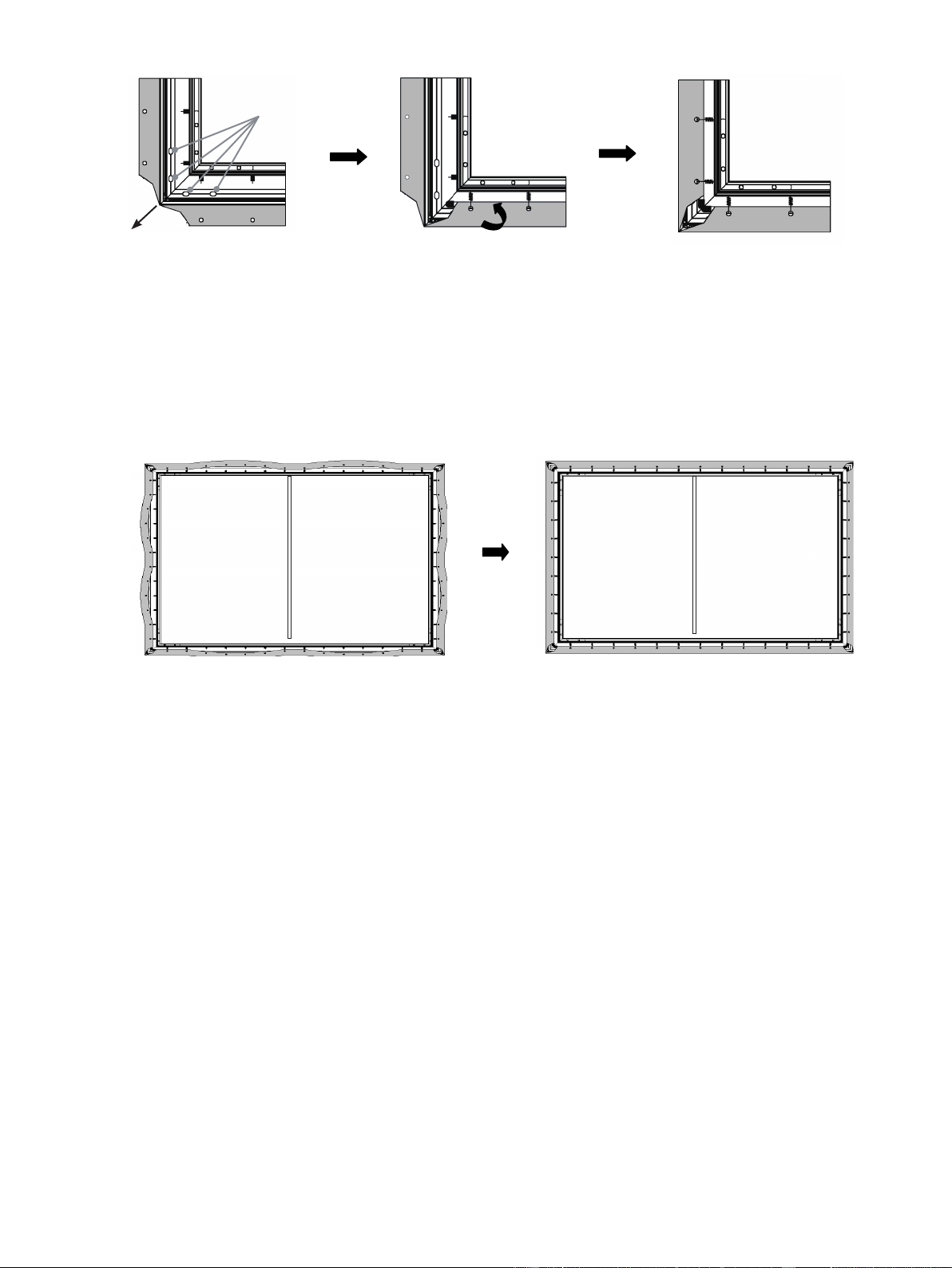
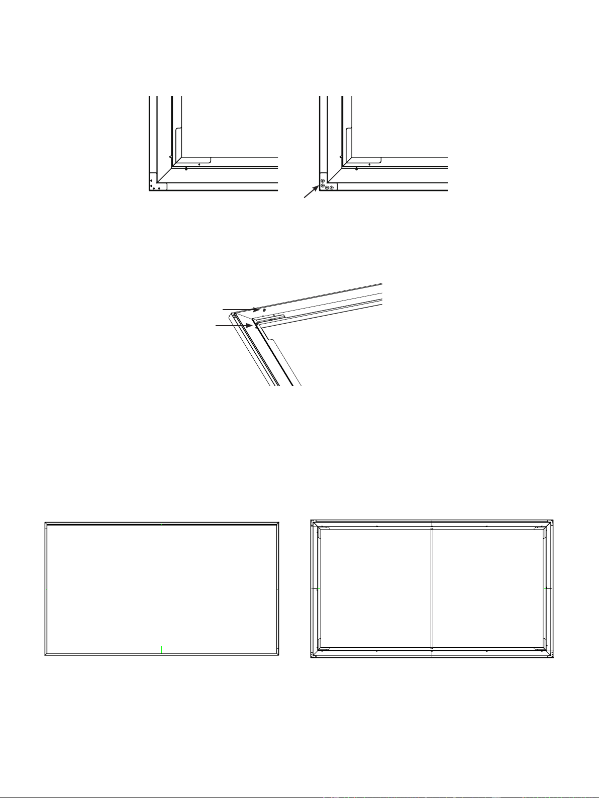
4. Place the
L
Corner Fitting (P)
on the four corners. When the
L Corner Fitting (P)
fits the outer frame completely, then
tighten the screws into holes .
Attention:
• You are not suggested to screw the plastic
L Corner Fitting (P)
too tight because high twisting force could cause slip of L
corner fitting. The proposed force is less than 0.3 N.M.
5.
For the long frame, 6 screws need to be used; for the short frame, 3 screws need to be used.
Align the
L1, L2, M
with the Frame corners and the holes.
6. Look at the screen horizontally, and if you find the material is black, it is in the correct direction and ready for mounting on
the wall. However, if the material is white, turn around the screen and then install it.
When you are nished, the front and back of the screen should appear as shown below.
M3x7 screw (N)
M3x7 screw (N)
N
Front side Back side

11
CHECK THE SIZE OF YOUR SPACE
Width ≥ 118.11inches (3.0m)
Height ≥ 78.74
inches
(2.0m) from the installation surface to the ceiling.
For the optimal viewing experience, we recommend a minimum viewing distance of 177 inches (4.5m) from the screen.
RECOMMENDED SIZE FOR YOUR TV STAND
We recommend that you place your Laser TV on a TV stand that is at about 20 inches (50 cm) tall and 16 inches (42
cm) wide to hold the TV.
Prepare Your Space
W≥118.11 inches (3.0m)
paper template
H2=73.94
inches
(1.878m)
H1≥78.74 inches
(2.0m)
the TV stand
H3=71.18 inches
(1.808m)
L1=14.65 inches
(0.372m)
H=16.73 inches
(0.425m)
Installing the Wall Mount Brackets
Perfect!
Check the Type of Wall You Have
Drywall with studs?
Solid concrete or
concrete block?
Perfect!
Minimum wood stud size: common
2 x 4 in. (51 x 102mm) nominal 1½ x 3½ in. (38 x 89mm)
Minimum solid concrete thickness: 8 in. (203mm)
Minimum concrete block size:
common 8 x 8 x 16 in. (203 x 203 x 406mm)
Place screen onto the wall-mount brackets.
Tip: Picture is only for reference and may be different from the actual product.
Height of
12
IF YOU HAVE A DRYWALL WITH WOOD STUDS
NOTE: Make sure you have your stud finder.
4.
Use a stud nder to nd the studs in the areas on the paper template, and mark the center of the studs with a pencil. Following
the vertical line on the paper template, mark where the bottom screws should be within the proposed area.
5.
On the marks, drill the holes for the four screws.
6.
Remove the paper template and install the brackets with the screws. Firmly tighten the screws.
NOTE: Hold the bracket in place when tightening the screw to keep the bracket from shifting.
Install the Wall Mount Brackets
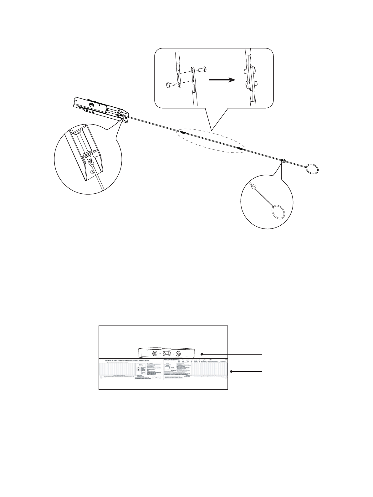
NOTE: Make sure you have your paper template, pencil, tape, level and screwdriver.
1.
Starting from the top of your TV stand, add
73 inches
(1.853m)
above it to get the height of the top of the paper template.
Mark the height onto the wall.
2.
Put the paper template on the center of the wall.
NOTE: The paper template should match the mark you made on the wall.
3.
Make sure the paper template is level.
Level
Paper template
Connecting the Wands
Connect the wands as shown in the illustration below.
13
Insert anchors
CAUTION:
All screws MUST BE firmly tightened to prevent unwanted movement of the brackets. Make sure the
brackets are securely fastened to the wall before continuing on to the next step.
7.
Attach the upper and lower parts of the wall bracket wands with the screws and bolts. Make sure the two parts are aligned and
rmly tighten the screws.
8.
Hang the wands on to the wall-mount brackets.
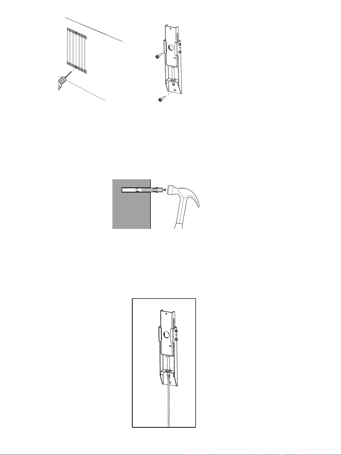
IF YOU HAVE A SOLID CONCRETE OR CONCRETE BLOCK WALL
NOTE: Make sure you have your concrete anchors and hammer.
4.
Drill holes for the top screws. Following the vertical line on the paper template, drill holes for the bottom screws within the
proposed area.
5.
Remove the paper template and insert four anchors into the holes.
Be sure the anchors are flush with the concrete surface.
6.
Install the brackets with the screws and rmly tighten them.
NOTE: Hold bracket in place when tightening the screw to keep the bracket from shifting.
Drill the holes
1
Install the brackets
with the screws
2
14
Hang the Screen
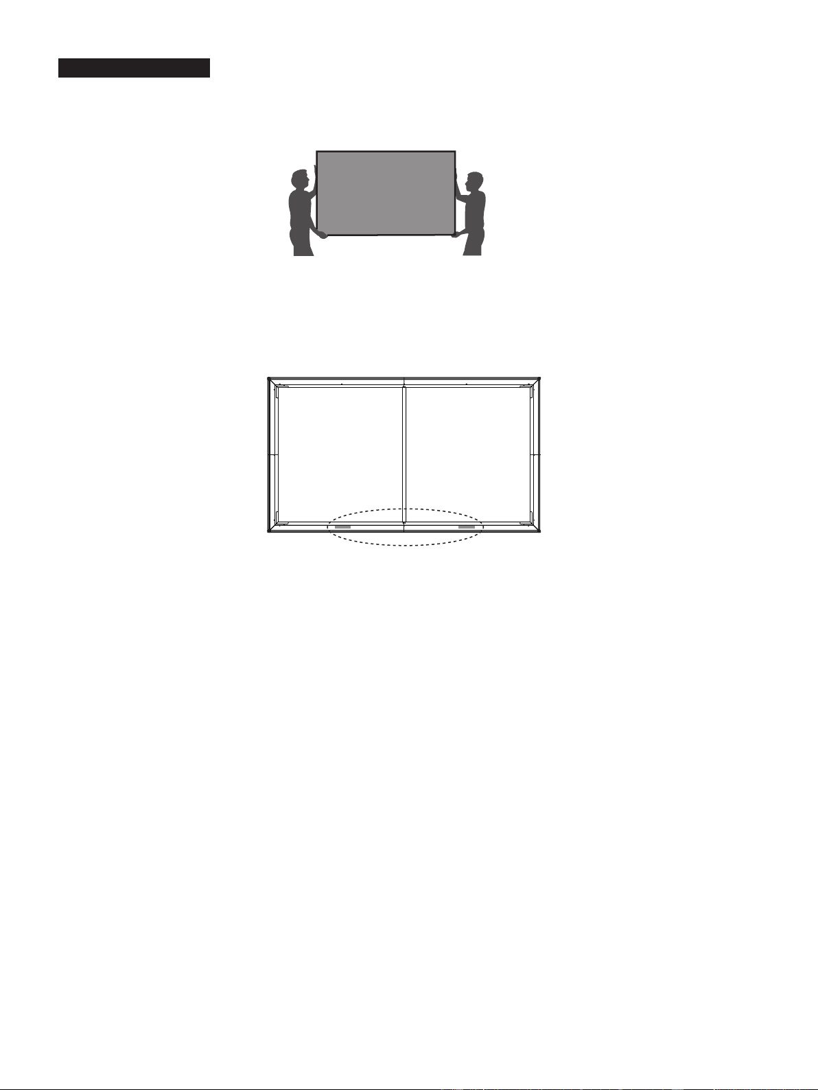
1.
We strongly recommend that two people handle this screen when moving it. Be sure to use gloves (included) to protect the screen
from grease, sweat and dirt.
2.
Place the assembled screen vertically on the ground.
Look at the screen horizontally
, and if you nd the material is black, it is in
the correct direction and ready for mounting on the wall. However, if the material is white, turn around the screen and then install
it.
3. Split the release paper on one side of the velcro strips. Paste the velcro strips on the left and right side of the bottom of the
screen (on the back side of the screen).
4.
Place the screen onto the brackets.
NOTE:
We do not recommend mounting the laser TV console to the ceiling. If you choose to, the orientation of the
screen will need to be reversed. Because in that case the function of offsetting the environment light will be diminished.
5.
Adjust the Height of the Screen
Attach the handles of the wands on the wall-mount brackets and adjust the height of the screen. Refer to the top border to
match the screen to the display image.
WARNING:
Do not look directly at the lens when this device is on because the laser light may damage your eyes!
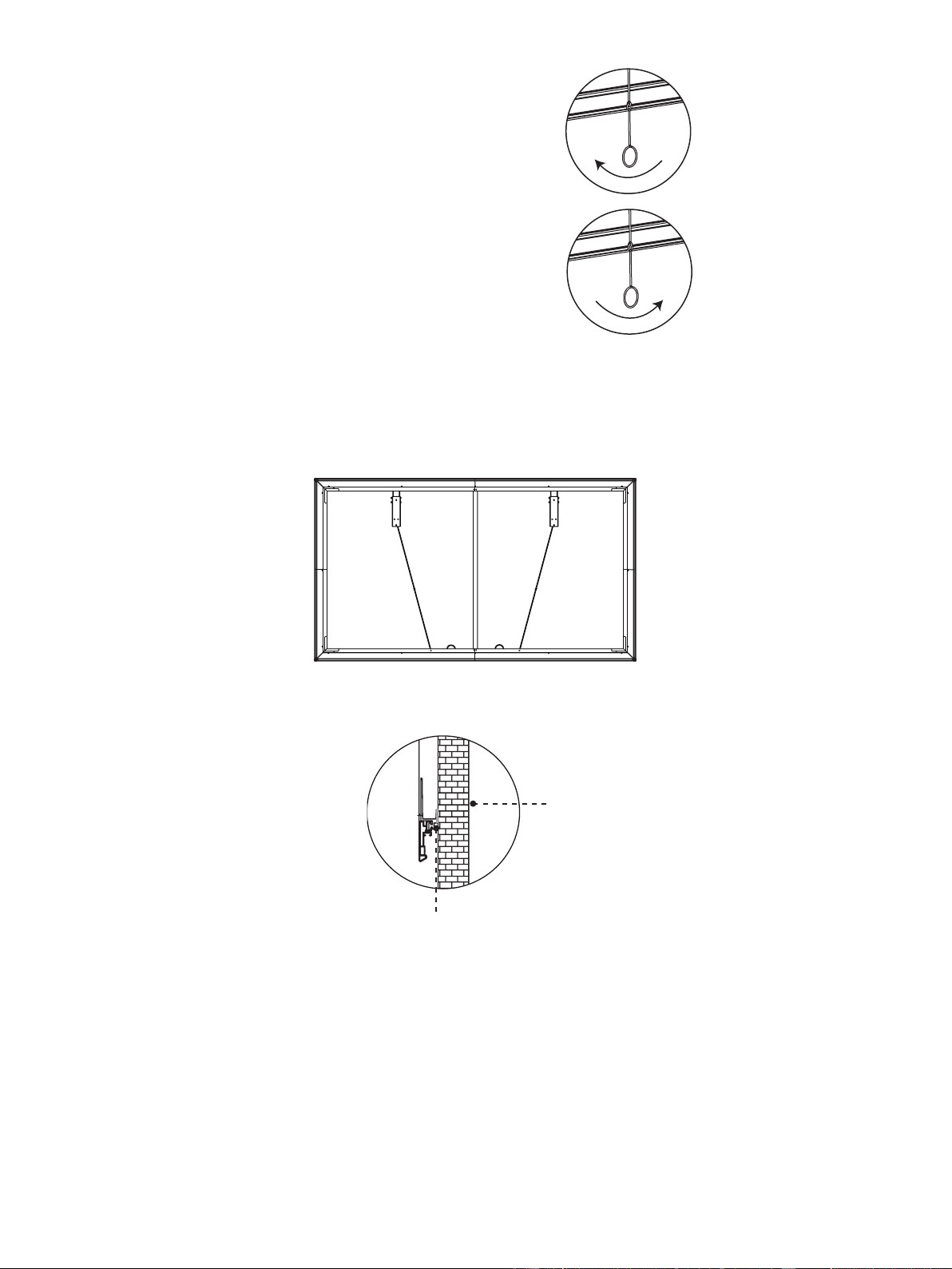
15
If the screen is higher than the image, then rotate the
wands clockwise and move the screen down.
If the screen is lower than the image, then rotate the
wands counterclockwise and move the screen up.
After you've completed adjusting the screen height, remove the handles. Fold and rest the wands on the screen bracket on the
bottom of the screen.
Wall
Velcro Strips
Disclaimer:
All products, product specications, and data are subject to change without notice to improve
reliability, function, design or otherwise.
6.
Make sure the screen is horizontally and vertically level. To prevent the bracket wands from keeping the screen from being
vertically level, fold and rest them on the screen bracket on the bottom of the screen (see the diagram).
7. When nishing adjusting the positon of screen, split the release paper on the other side of the two velcro strips. Remove the
foam support and push the screen to the wall.
