
DC Programmable Electronic
Loads
IT8500plus Series User Manual
Model:IT8511+/IT8511A+/IT8511B+/IT8512+/IT8512A
+/IT8512B+/IT8512C+/IT8512H+/IT8513A+/IT8513B
+/IT8513C+/IT8514C+/IT8514B+/IT8516C+
Version: 2.1

Notices
© Itech Electronic, Co., Ltd. 2018
No part of this manual may be
reproduced in any form or by any means
(including electronic storage and
retrieval or translation into a foreign
language) without prior permission and
written consent from Itech Electronic,
Co., Ltd. as governed by international
copyright laws.
Manual Part Number
IT8500+-402008
Revision
Second Edition: Mar. 15,
2018
Itech Electronic, Co., Ltd.
Trademarks
Pentium is U.S. registered trademarks
of Intel Corporation.
Microsoft, Visual Studio, Windows and
MS Windows are registered trademarks
of Microsoft Corporation in the United
States and/or other countries and
regions.
Warranty
The materials contained in this
document are provided “as is”, and
is subject to change, without prior
notice, in future editions. Further, to
the maximum extent permitted by
applicable laws, ITECH disclaims
all warrants, either express or
implied, with regard to this manual
and any information contained
herein, including but not limited to
the implied warranties of
merchantability and fitness for a
particular purpose. ITECH shall
not be held liable for errors or for
incidental or indirect damages in
connection with the furnishing, use
or application of this document or of
any information contained herein.
Should ITECH and the user enter
into a separate written agreement
with warranty terms covering the
materials in this document that
conflict with these terms, the
warranty terms in the separate
agreement shall prevail.
Technology Licenses
The hardware and/or software
described herein are furnished under a
license and may be used or copied only
in accordance with the terms of such
license.
Restricted Rights Legend
Restricted permissions of the U.S.
government. Permissions for software
and technical data which are authorized
to the U.S. Government only include
those for custom provision to end users.
ITECH follows FAR 12.211 (technical
data), 12.212 (computer software).
DFARS 252.227-7015 (technical
data--commercial products) for national
defense and DFARS 227.7202-3
(permissions for commercial computer
software or computer software
documents) while providing the
customized business licenses of
software and technical data.
Safety Notices
A CAUTION sign denotes a
hazard. It calls attention to an
operating procedure or practice
that, if not correctly performed
or adhered to, could result in
damage to the product or loss of
important data. Do not proceed
beyond a CAUTION sign until
the indicated conditions are fully
understood and met.
A WARNING sign denotes a
hazard. It calls attention to an
operating procedure or practice
that, if not correctly performed
or adhered to, could result in
personal injury or death. Do not
proceed beyond a WARNING
sign until the indicated
conditions are fully understood
and met.
NOTE
A NOTE sign denotes
important hint. It calls attention
to tips or supplementary
information that is essential for
users to refer to.
IT8500+ User Manual
Copyright © Itech Electronic Co., Ltd. i
Quality Certification and Assurance
We certify that series IT8500+ electronic load meets all the published
specifications at time of shipment from the factory.
Warranty
ITECH warrants that the product will be free from defects in material and
workmanship under normal use for a period of one (1) year from the date of
delivery (except those described in the Limitation of Warranty below).
For warranty service or repair, the product must be returned to a service center
designated by ITECH.
The product returned to ITECH for warranty service must be shipped
PREPAID. And ITECH will pay for return of the product to customer.
If the product is returned to ITECH for warranty service from overseas, all
the freights, duties and other taxes shall be on the account of customer.
Limitation of Warranty
This Warranty will be rendered invalid in case of the following:
Damage caused by circuit installed by customer or using customer own
products or accessories;
Modified or repaired by customer without authorization;
Damage caused by circuit installed by customer or not operating our
products under designated environment;
The product model or serial number is altered, deleted, removed or made
illegible by customer;
Damaged as a result of accidents, including but not limited to lightning,
moisture, fire, improper use or negligence.
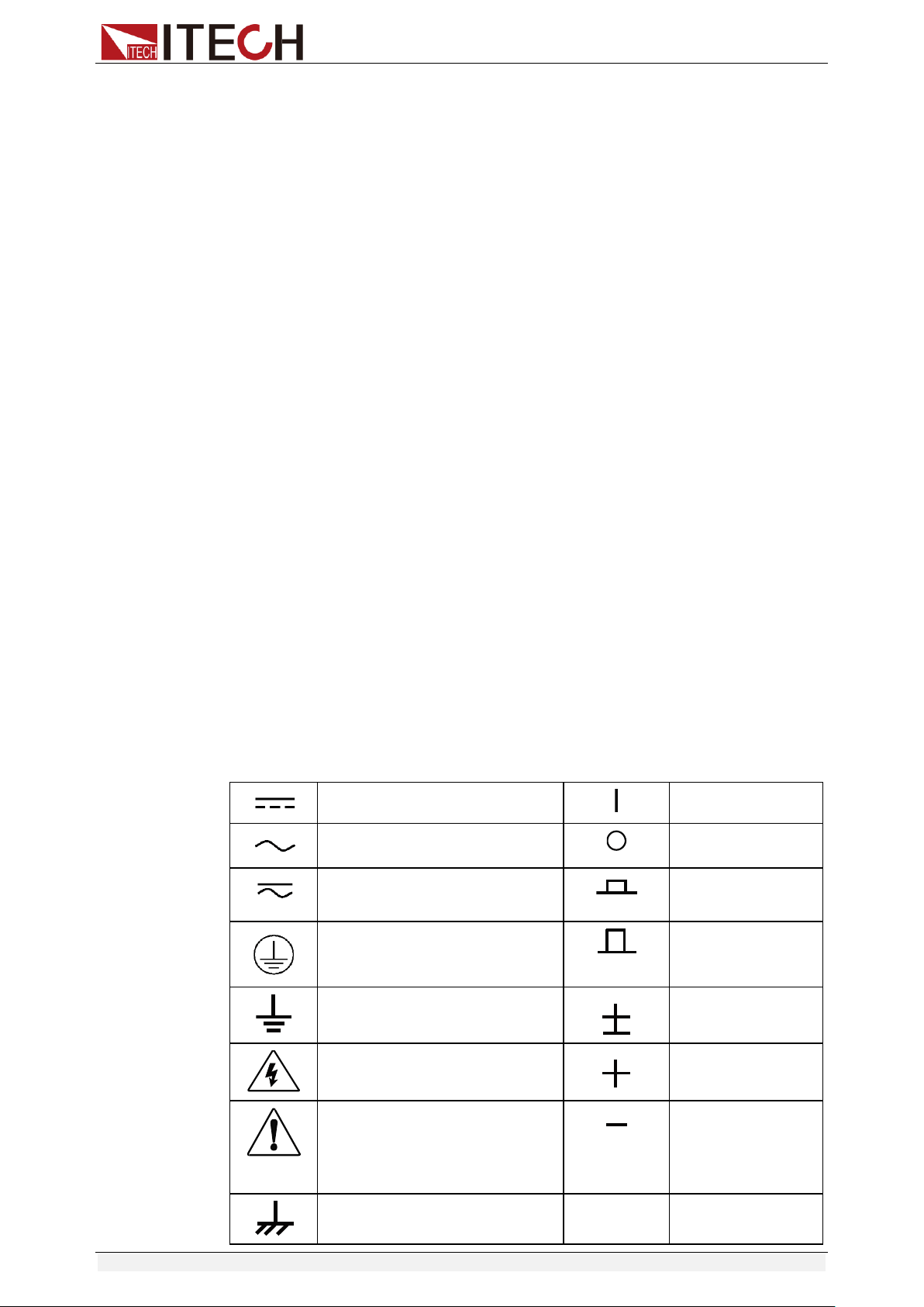
Safety Symbols
Direct current
ON (power on)
Alternating current
OFF (power off)
Both direct and alternating
current
Power-on state
Protective conductor terminal
Power-off state
Earth (ground) terminal
Reference
terminal
Caution, risk of electric shock
Positive terminal
Warning, risk of danger (refer
to this manual for specific
Warning or Caution
information)
Negative terminal
Frame or chassis terminal
-
-

IT8500+ User Manual
Copyright © Itech Electronic Co., Ltd. ii
Safety Precautions
The following safety precautions must be observed during all phases of
operation of this instrument. Failure to comply with these precautions or specific
warnings elsewhere in this manual will constitute a default under safety
standards of design, manufacture and intended use of the instrument. ITECH
assumes no liability for the customer’s failure to comply with these precautions.
Series IT8500+ electronic load supports 110V/220VAC input and need to
switch the input voltage before operation.
Do not use the instrument if it is damaged. Before operation, check the
casing to see whether it cracks. Do not operate the instrument in the
presence of inflammable gasses, vapors or dusts.
The electronic load is provided with a power line during delivery and should
be connected to a socket with a protective earth terminal. Before operation,
be sure that the instrument is well grounded.
Make sure to use the power cord supplied by ITECH.
Check all marks on the instrument before connecting the instrument to
power supply.
Use electric wires of appropriate load. All loading wires should be capable
of bearing maximum short-circuit current of electronic load without
overheating. If there are multiple electronic loads, each pair of the power
cord must be capable of bearing the full-loaded rated short-circuit output
current
Ensure the voltage fluctuation of mains supply is less than 10% of the
working voltage range in order to reduce risks of fire and electric shock.
Do not install alternative parts on the instrument or perform any
unauthorized modification.
Do not use the instrument if the detachable cover is removed or loosen.
To prevent the possibility of accidental injuries, be sure to use the power
adapter supplied by the manufacturer only.
We do not accept responsibility for any direct or indirect financial damage
or loss of profit that might occur when using the instrument.
This instrument is used for industrial purposes, do not apply this product to
IT power supply system.
Never use the instrument with a life-support system or any other equipment
subject to safety requirements.
Failure to use the instrument as directed by the manufacturer may render
its protective features void.
Always clean the casing with a dry cloth. Do not clean the internals.
Make sure the vent hole is always unblocked.
IT8500+ User Manual
Copyright © Itech Electronic Co., Ltd. iii
Environmental Conditions
The instrument is designed for indoor use and an area with low condensation.
The table below shows the general environmental requirements for the
instrument. The speed of fan will change intelligently by the temperature of
radiator. When the temperature is up to 40°C, the fan will be on and adjust
intelligently when temperature changes.
Environmental Conditions
Requirements
Operating temperature
0°C to 40°C
Operating humidity
20%-80% (non-condensation)
Storage temperature
-20°C to 70 °C
Altitude
Operating up to 2,000 meters
Pollution degree
Pollution degree 2
Installation category
II
Note
To make accurate measurements, allow the instrument to warm up for 30 min before
operation.
Regulatory Markings
The CE mark indicates that the product
complies with all the relevant European
legal directives. The specific year (if any)
affixed refers to the year when the design
was approved.
The instrument complies with the WEEE
Directive (2002/96/EC) marking
requirement. This affixed product label
indicates that you must not discard the
electrical/electronic product in domestic
household waste.
This symbol indicates the time period
during which no hazardous or toxic
substances are expected to leak or
deteriorate during normal use. The
expected service life of the product is 10
years. The product can be used safely
during the 10-year Environment Friendly
Use Period (EFUP). Upon expiration of
the EFUP, the product must be
immediately recycled.
Waste Electrical and Electronic Equipment (WEEE)
Directive
2002/96/EC Waste Electrical and Electronic Equipment
(WEEE) Directive
This product complies with the WEEE Directive (2002/96/EC)
marking requirement. This affix product label indicates that you
must not discard the electrical/electronic product in domestic
household waste.
Product Category

IT8500+ User Manual
Copyright © Itech Electronic Co., Ltd. iv
With reference to the equipment classifications described in the
Annex I of the WEEE Directive, this instrument is classified as a
“Monitoring and Control Instrument”.
To return this unwanted instrument, contact your nearest
ITECH office.

IT8500+ User Manual
Copyright © Itech Electronic Co., Ltd. v
Compliance Information
Complies with the essential requirements of the following applicable European
Directives, and carries the CE marking accordingly:
Electromagnetic Compatibility (EMC) Directive 2014/30/EU
Low-Voltage Directive (Safety) 2014/35/EU
Conforms with the following product standards:
EMC Standard
IEC 61326-1:2012/ EN 61326-1:2013 ¹²³
Reference Standards
CISPR 11:2009+A1:2010/ EN 55011:2009+A1:2010 (Group 1, Class A)
IEC 61000-4-2:2008/ EN 61000-4-2:2009
IEC 61000-4-3:2006+A1:2007+A2:2010/ EN 61000-4-3:2006+A1:2008+A2:2010
IEC 61000-4-4:2004+A1:2010/ EN 61000-4-4:2004+A1:2010
IEC 61000-4-5:2005/ EN 61000-4-5:2006
IEC 61000-4-6:2008/ EN 61000-4-6:2009
IEC 61000-4-11:2004/ EN 61000-4-11:2004
1. The product is intended for use in non-residential/non-domestic environments. Use of the
product in residential/domestic environments may cause electromagnetic interference.
2. Connection of the instrument to a test object may produce radiations beyond the specified
limit.
3. Use high-performance shielded interface cable to ensure conformity with the EMC standards
listed above.
Safety Standard
IEC 61010-1:2010/ EN 61010-1:2010

IT8500+ User Manual
Copyright © Itech Electronic Co., Ltd. vi
Content
Quality Certification and Assurance ............................................................................................................................ i
Warranty ..................................................................................................................................................................... i
Limitation of Warranty ................................................................................................................................................ i
Safety Symbols ............................................................................................................................................................ i
Safety Precautions ...................................................................................................................................................... ii
Environmental Conditions ......................................................................................................................................... iii
Regulatory Markings ................................................................................................................................................. iii
Waste Electrical and Electronic Equipment (WEEE) Directive ................................................................................... iii
Compliance Information ............................................................................................................................................ v
Chapter1 Inspection and Installation ............................................................................................................. 1
1.1 Verifying the Shipment ......................................................................................................................................... 1
1.2 Instrument Size Introduction ............................................................................................................................... 3
1.3 Adjustment of Load Handle ................................................................................................................................. 6
1.4 Disassembly of Load Handle ................................................................................................................................ 7
1.5 Rack Mounting ..................................................................................................................................................... 8
1.6 Connect the Power Cord ...................................................................................................................................... 8
1.7 Connect the Device Under Test (DUT) .................................................................................................................. 9
Chapter2 Quick Start ................................................................................................................................... 12
2.1 Brief Introduction ............................................................................................................................................... 12
2.2 Product Feature .................................................................................................................................................. 12
2.3 Front Panel Introduction .................................................................................................................................... 13
2.4 Front Panel Keys ................................................................................................................................................. 14
2.5 Combination Keys............................................................................................................................................... 15
2.6 VFD Annunciators ............................................................................................................................................... 15
2.7 Rear Panel Introduction ..................................................................................................................................... 16
2.8 Power-on Selftest ............................................................................................................................................... 17
Chapter3 Functions and Characteristics ....................................................................................................... 20
3.1 Local Mode/Remote Mode ................................................................................................................................ 20
3.2 Operation Mode ................................................................................................................................................. 20
3.2.1 Constant Current Mode (CC)................................................................................................................. 20
3.2.2 Constant Voltage Mode (CV) ................................................................................................................. 21
3.2.3 Constant Resistance Mode (CR) .......................................................................................................... 22
3.2.4 Constant Power Mode (CW) .................................................................................................................. 23
3.3 Input On/Off Control .......................................................................................................................................... 23
3.4 Key Lock Function ............................................................................................................................................... 24
3.5 Short-circuit Analog Function............................................................................................................................. 24
3.6 System Menu (System) ....................................................................................................................................... 24
3.7 Config Menu (Config) ......................................................................................................................................... 26
3.8 Trigger Function ................................................................................................................................................. 27
3.9 LIST Operation .................................................................................................................................................... 28
3.10 Test Function .................................................................................................................................................... 30
3.10.1 Transient Test Function ........................................................................................................................ 30
3.10.2 OCP Test Function ................................................................................................................................ 33
3.10.3 OPP Test Function ................................................................................................................................ 34
3.10.4 Battery Discharge Test ......................................................................................................................... 35
3.10.5 CR-LED Test Function ......................................................................................................................... 37
3.10.6 Measurement of Voltage Rise Time ................................................................................................... 39
3.11 Saving and Recalling Settings ........................................................................................................................... 39
3.12 VON Function ................................................................................................................................................... 40
3.13 Protection Function .......................................................................................................................................... 41
3.14 Current Monitoring (I Monitor) ........................................................................................................................ 42
3.15 Ripple Function ................................................................................................................................................ 42
Chapter4 Automatic Test Function ............................................................................................................... 44
4.1 Introduction ....................................................................................................................................................... 44
4.2 Automatic Test Mode Switching ......................................................................................................................... 44

IT8500+ User Manual
Copyright © Itech Electronic Co., Ltd. vii
4.2.1 Test Mode for IT8500+ ........................................................................................................................... 45
4.2.2 Test Mode for IT8500 .............................................................................................................................. 48
Chapter5 Specifications ............................................................................................................................... 51
Specifications ........................................................................................................................................................... 51
Supplementary Characteristics ................................................................................................................................ 65
Chapter6 Communication Interfaces ........................................................................................................... 66
6.1 Communication Modules Introduction .............................................................................................................. 66
6.2 Communication with PC ..................................................................................................................................... 68
Appendix .............................................................................................................................................................. 70
Specifications of Red and Black Test Lines ............................................................................................................... 70
Inspection and Installation
Copyright © Itech Electronic Co., Ltd. 1
Chapter1 Inspection and Installation
1.1 Verifying the Shipment
Unpack the box and check the contents before operating the instrument. If
wrong items have been delivered, if items are missing, or if there is a defect
with the appearance of the items, contact the dealer from which you purchased
the instrument immediately. The package contents include:
Checklist of Package Contents
Item
Qty.
Model
Remarks
Electronic Loads
x1
IT8500+ series
The IT8500+ series include:
IT8511+/IT8511A+/IT8511B+/IT8
512+/IT8512A+/IT8512B+/IT851
2C+/IT8512H+/IT8513A+/IT851
3B+/IT8513C+/IT8514C+/IT851
4B+/IT8516C+
Power cord
x1
IT-E171/IT-E17
2/IT-E173/IT-E1
74
User may select an appropriate
power cord that matches the
specifications of power socket
used in the area. See the
Section Connecting the Power
Cord for details.
CD
x1
-
It contains IT8500+ electronic
load User’s Manual,
Programming Guide and other
user documentations.
Ex-factory Test
Report
x1
-
It is the test report of the
instrument before delivery.
NOTE
Upon verification of the shipment, keep the package and relevant contents thereof in a
safe place. When returning the instrument for warranty service or repair, the specified
packing requirements shall be met.
The IT8511+/IT8511A+/IT8511B+/IT8512+/IT8512A+/IT8512B+/IT8512H+/
IT8512C+/IT8512H+/IT8512C+/IT8513A+/IT8513C+ models have separately
sold optional accessories. Please refer to Chapter5 Communication
Interfaces for details of each accessory.
Device Name
Model
Accessories Description
Rack mount kit
IT-E151
Select this accessory when the user needs
to install the instrument on a special
bracket.
RS232
Communication
Module
IT-E121
Select this accessory when users need to
use the standard RS232 extension cable to
connect the DB9 interface connector of the
DC load and the RS-232 interface
connector of computer for the
communication.
RS232
Communication
Module
IT-E121A
The DB9 interface connector of the RS232
changes from female to male, so that can
be directly connected to the standard LAN
interface.

Inspection and Installation
Copyright © Itech Electronic Co., Ltd. 2
Device Name
Model
Accessories Description
USB
Communication
Module
IT-E122
Select this accessory when you need to
use IT-E122 and an a standard USB
extension cable (type B female connector
at one end and type A at one end) to
connect the DB9 interface connector of the
DC load and the USB interface connector
of computer for the communication.
RS485
Communication
Module
IT-E123
Select this accessory when you need to
use the communication module IT-E123
and a standard RS485-RS232 conversion
cable to connect the DB9 interface
connector of the DC load and the RS-232
interface connector of computer for the
communication.
Inspection and Installation
Copyright © Itech Electronic Co., Ltd. 3
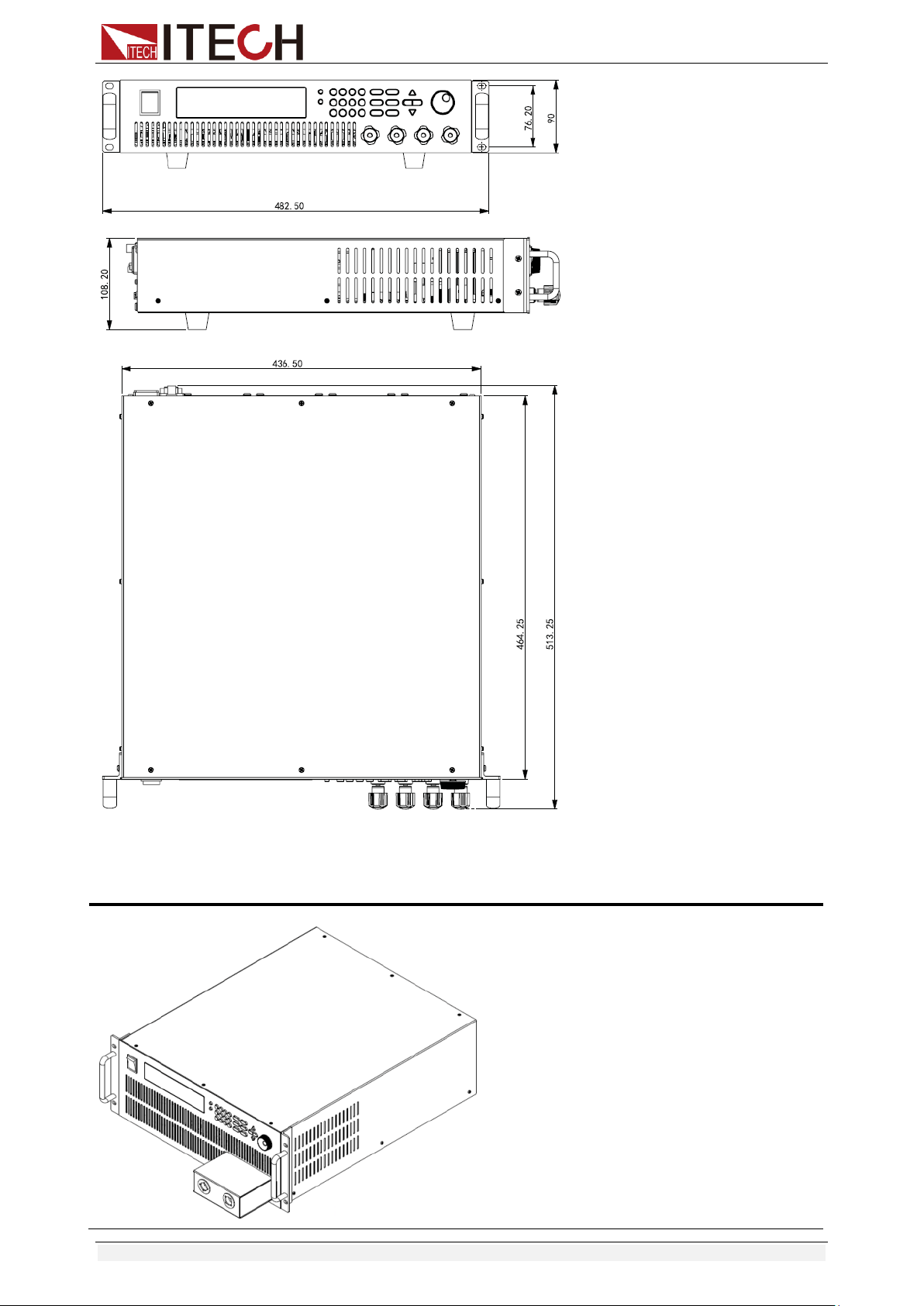
1.2 Instrument Size Introduction
The instrument should be installed at well-ventilated and rational-sized space.
Please select appropriate space for installation based on the electronic load
size.
IT8500+ series electronic load different models are not the same size, the detail
size of the electronic load is shown as below.
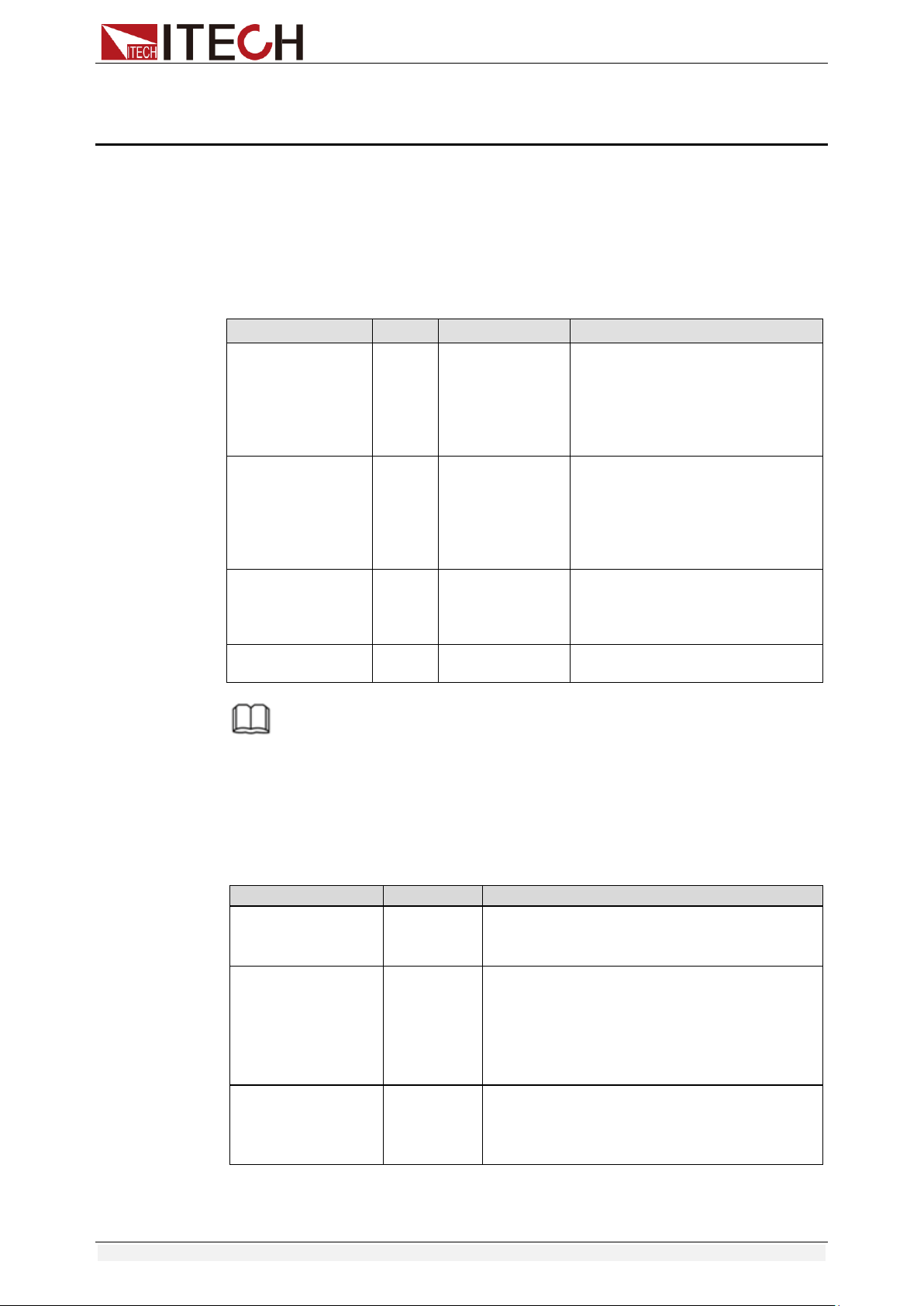
IT8511+/IT8511A+/IT8511B+/IT8512+/IT8512B+/IT8512C+/IT8512H+ Model
Detailed Dimension Drawing
Inspection and Installation
Copyright © Itech Electronic Co., Ltd. 4
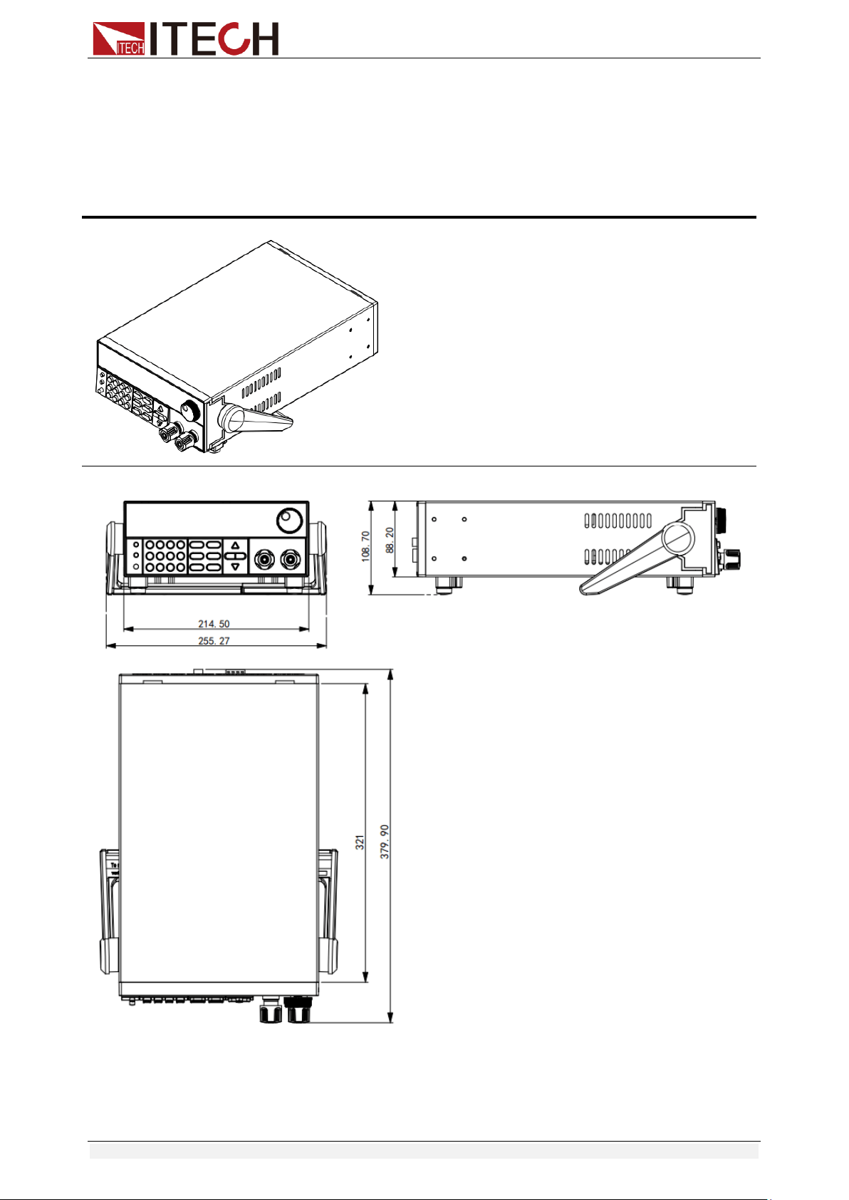
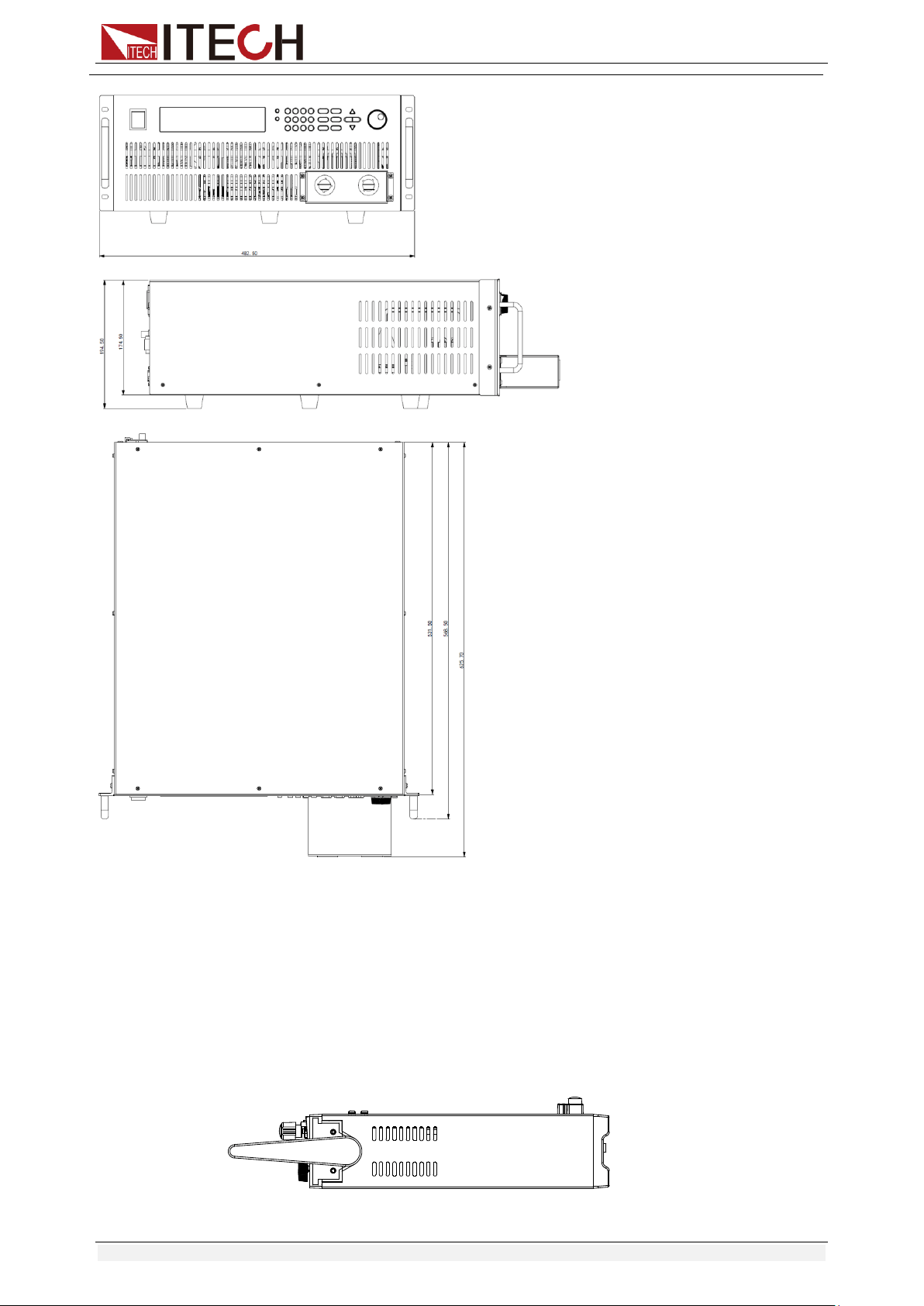
IT8513A+/IT8513C+ Model
Detailed Dimension Drawing
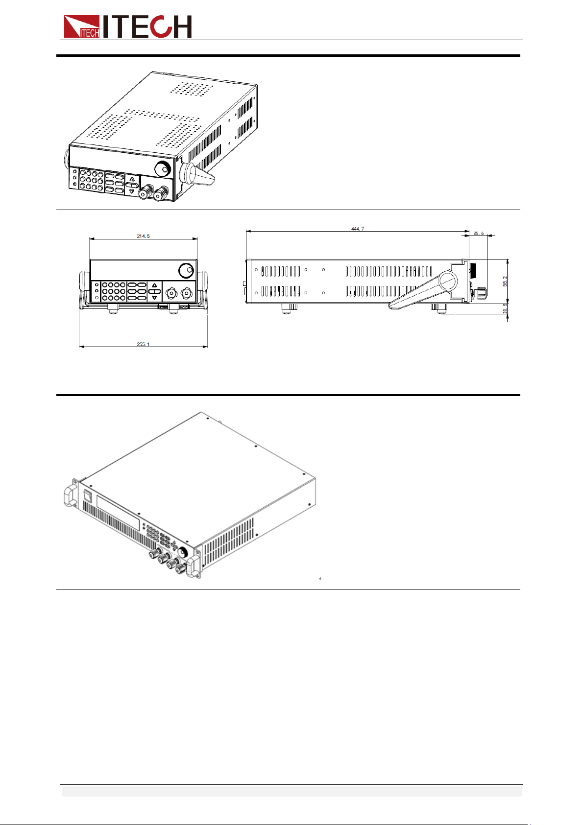
IT8513B+/IT8514B+/ IT8514C+ Model
Detailed Dimension Drawing
Inspection and Installation
Copyright © Itech Electronic Co., Ltd. 5
IT8516C+ Model
Inspection and Installation
Copyright © Itech Electronic Co., Ltd. 6
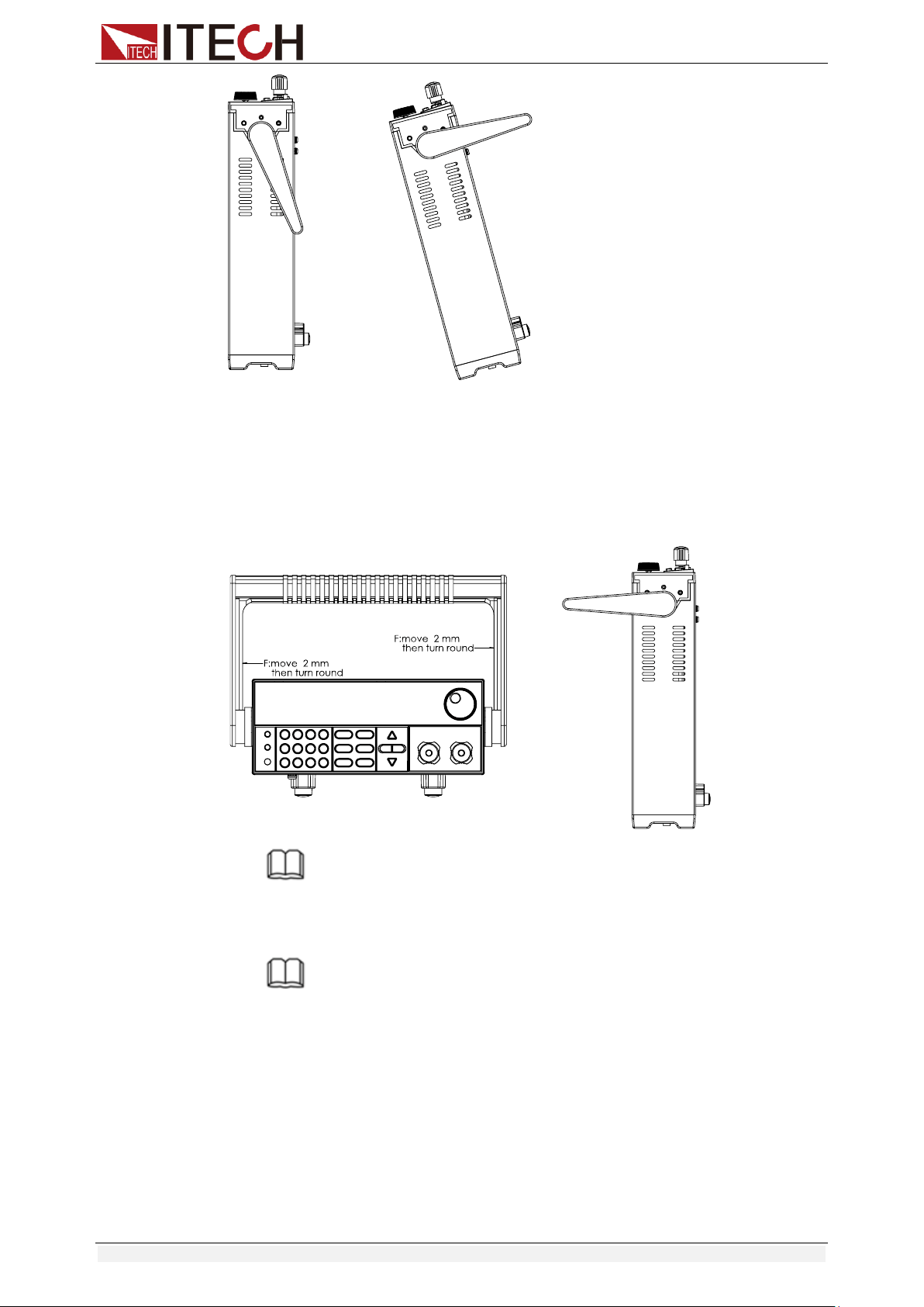
1.3 Adjustment of Load Handle
IT8511+/IT8511A+/IT8511B+/IT8512+/IT8512A+/IT8512B+/IT8512C+/IT8512H
/IT8513A+/IT8513C+ series loads are equipped with a handle for user to easily
carry and place it.
The load handle may be adjusted based on three methods (as shown in icons
below). Be sure that appropriate force is applied to adjust the load handle to
appropriate position.
Detailed Dimension Drawing
Inspection and Installation
Copyright © Itech Electronic Co., Ltd. 7
1.4 Disassembly of Load Handle
Please disassemble the load handle before installing equipment on the support.
Disassembly steps:
1. Adjust the handle to the position as shown in the figure below.
NOTE
To easily disassemble handle, align the locking mouth and locking device, which is between
the handle and the instrument.
2. Align the locking mouth, and pull out the handle towards two sides.
NOTE
Do not use too much force and mind your hands during disassembly of load handle.

Inspection and Installation
Copyright © Itech Electronic Co., Ltd. 8
1.5 Rack Mounting
IT8511+/IT8511A+/IT8511B+/IT8512+/IT8512A+/IT8512B+/IT8512C+/IT8512H
+/IT8513A+/IT8513C+ loads can be installed on standard 19-inch rack. ITECH
provides user with IT-E151/IT-E151A rack, as an optional mount kit. The
detailed operation please refer to the User Manual of your mount kit.
IT8513B+/IT8514B+/IT8514C+/IT8516C+ need not mount on rack, they can be
installed on cabinet directly by screw.
1.6 Connect the Power Cord
Before connecting the power cord
To prevent electric shock and damage to the instrument, observe the following
precautions.
Before connecting the power cord, please confirm the 110V / 220V transfer
switch to ensure that the switch of the load matches the supply voltage.
Otherwise, the instrument may be damaged.
Connect the power cord after checking that the power switch of the
instrument is turned OFF. Only use the power cord supplied as a standard
accessory.
To prevent electric shock, be sure to take protective earthing. Please
connect the power cable to the socket with the protective earth terminal.
Do not use the extension cord without protective grounding function,
otherwise the protection function will be invalid.
Please use the AC power socket matching the power cord shipped with the
box and take the protective earthing measures. If you can not use a
suitable AC power cord, do not use the instrument.
Power cord type
Select from the following Schedule of Power Cord Specifications an appropriate
power cord that matches the voltage for the area in which you use the
instrument. If the power cord included in the instrument you purchased does
not match the voltage, contact the dealer or manufacturer for change.
China
IT-E171
United States &
Canada
IT-E172
Europe
IT-E173
England
IT-E174
AC input level
A transfer switch is selectable on the rear panel:
Option Opt.1: 220V ±10% 50Hz/60Hz
Option Opt.2: 110V ±10% 50Hz/60Hz

Inspection and Installation
Copyright © Itech Electronic Co., Ltd. 9
Steps
1. Check whether the power switch of the instrument is turned OFF.
2. Connect one end of the power cord to the AC input connector on the rear
panel of the instrument.
3. Connect the other end of the power cable to the socket configured with
protective earth.
1.7 Connect the Device Under Test (DUT)
Before connecting the DUT
To prevent electric shock and damage to the instrument, observe the following
precautions.
Before connecting the DUT, turn off the power of the test loop to avoid the
risk of electric shock during connection.
To avoid electrical shock, before testing, please make sure the rating
values of the testing cables, and do not measure the current that higher
than the rating value.
Always use test cables provided by ITECH to connect the equipment. If
test cables from other factories are used, please check that the test cable
can withstand maximum current.
Specification
Test cables are not standard accessories of the instrument. Please select
optional red and black test cables for individual sales based on the maximum
current value. For specifications of test cables and maximum current values,
refer to “Specifications of Red and Black Test Lines” in “Appendix”.
Introduction of Binding Posts
The IT8500+ series (except IT8516C+) load front panel contains the following
terminals and the maximum rated current of the terminal at position (A) is the
maximum rated input current of the instrument. Securely fasten all wires by
hand-tightening the binding posts. You can also insert standard banana plugs
into the front of the connectors as shown in (B), and the maximum rated current
at (B) is 10 A.
Local measurement
1. Check whether the power switch is in Off position.
2. (Optional) Unlock the load input terminal cover.
3. Unscrew the screws of the input terminals. Connect the red and black test
cables to the input terminals. Re-tighten the screws.
When maximum current that one test cable can withstand fails to meet the
Inspection and Installation
Copyright © Itech Electronic Co., Ltd. 10
current rated current, use several pieces of red and black test cables. For
example, the maximum current is 1,200A, then 4 pieces of 360A red and
black cables are required.
4. (Optional) Install the load input terminal cover.
5. Directly connect the other end of the red and black cables to the DUT
terminal.
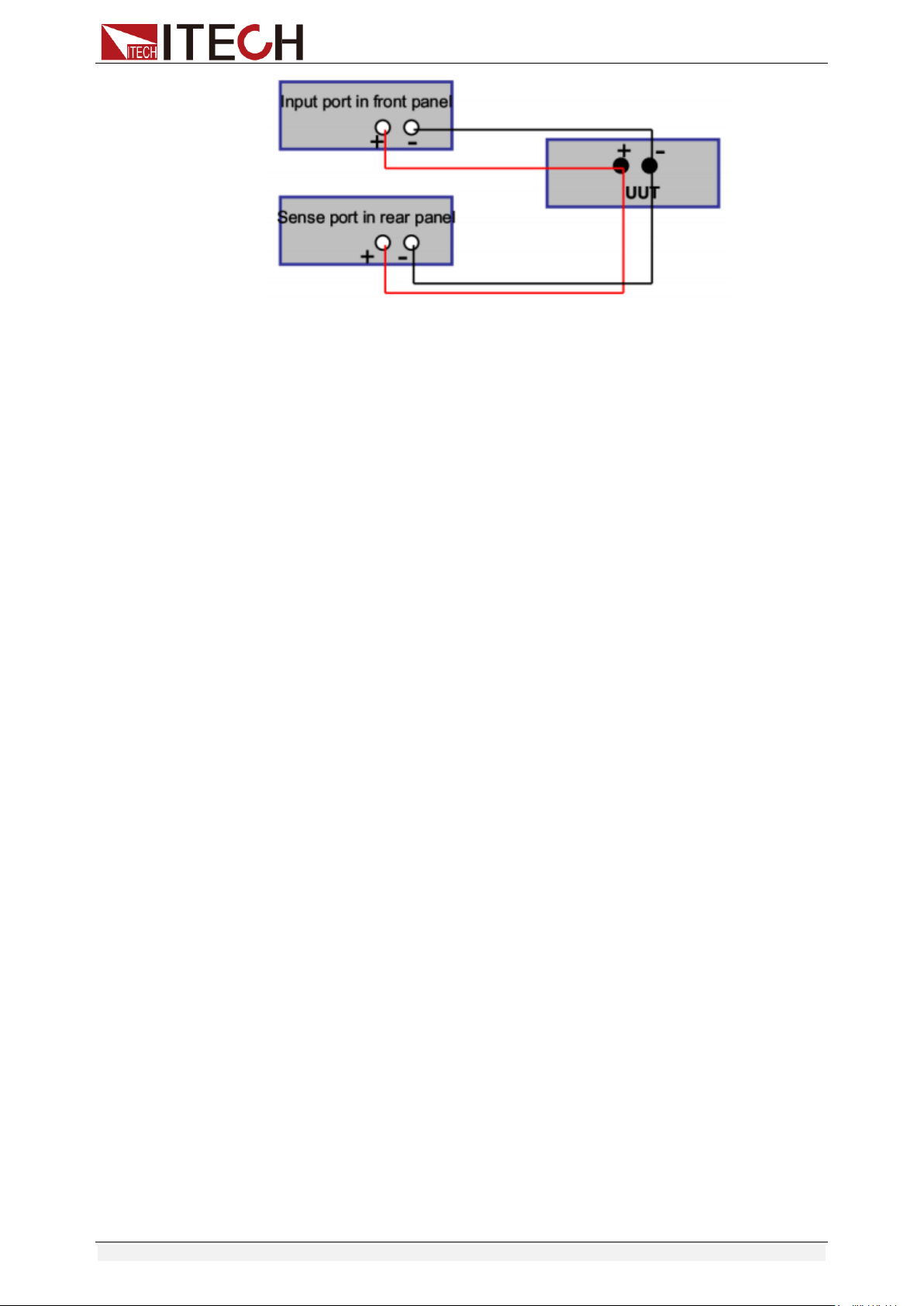
Remote measurement
Remote sensing is used to counteract the effect of lead resistance. For
example, if you connect a power supply to the DC Load, the voltage at the
power supply's terminals will not be the same as the voltage at the DC Load's
terminals if there is a current flowing because of the finite resistance from the
wires. Using remote sensing, you can sense the voltage at the power supply's
terminals, effectively removing the effect of the voltage drop in the connection
wire.
When using remote sensing, the power displayed by the instrument includes
both the power dissipated inside the instrument and the power dissipated in the
leads from the power supply to the DC Load's input terminals.
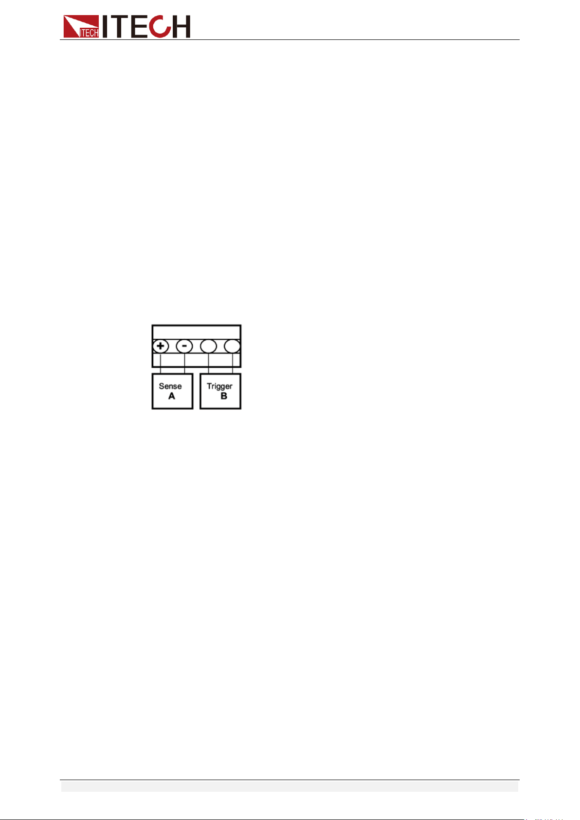
Sense terminals in the rear panel displayed as follows:
Remote Sensing: SENSE (+) and SENSE (–) are the remote sensing inputs.
By eliminating the effect of the inevitable voltage drop in the DC load leads,
remote sensing provides greater accuracy by allowing the DC load to regulate
directly at the source's output terminals.
Before using the remote measurement function, you must first set the load to
remote measurement mode. The steps are as follows:
1. Press [Shift] + [9] key into the menu.
2. Press Right/Left key to select SENSE, press [Enter] key to confirm.
3. Select ON, then the remote sense function has been set.
Note:
When not using the remote measurement function, press the OFF key to
close the remote measurement mode.
4. Refer the following diagram to connect test cables.
Wiring Diagram for Remote Sensing:
Inspection and Installation
Copyright © Itech Electronic Co., Ltd. 11
Note:
Test cables and Sense cables should be as short as possible, and Sense
cables should be twisted together.
Quick Start
Copyright © Itech Electronic Co., Ltd. 12
Chapter2 Quick Start
This chapter introduces the front panel, the rear panel, key functions and VFD
display function of the electronic load, make sure that you can quickly know the
appearance, instruction and the key function before you operate the load. Help
you better use this series of loads.
2.1 Brief Introduction
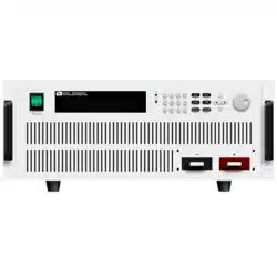
IT8500+ series is a single-channel programmable electronic load. With power
ranges from 150W to 3000W. The user can perform online voltage
measurements and adjustments or simulate short circuit test using the simple
keypad on the front panel. IT8500+ also offers a full-featured battery mode for
discharging test. IT8500+ series DC load is a versatile instrument for static and
dynamic testing of power supplies, batteries, AC-DC/DC-DC converters, battery
chargers, provides user the best testing solution.
Model
Voltage
Current
Power
Communication
Interface
IT8511+
120V
30A
150W
DB9(TTL)
IT8511A+
150V
30A
150W
DB9(TTL)
IT8511B+
500V
10A
150W
DB9(TTL)
IT8512+
120V
30A
300W
DB9(TTL)
IT8512A+
150V
30A
300W
DB9(TTL)
IT8512B+
500V
15A
300W
DB9(TTL)
IT8512C+
120V
60A
300W
DB9(TTL)
IT8512H+
800V
5A
300W
DB9(TTL)
IT8513A+
150V
60A
400W
DB9(TTL)
IT8513B+
500V
30A
600W
Standard USB/RS232
IT8513C+
120V
120A
600W
DB9(TTL)
IT8514B+
500V
60A
1500W
Standard USB/RS232
IT8514C+
120V
240A
1500W
Standard USB/RS232
IT8516C+
120V
240A
3000W
Standard USB/RS232
2.2 Product Feature
High-visibility vacuum fluorescent display (VFD)
Measurement resolution: 0.1mV,0.1mA
Voltage and current measurement speed: up to 40KHZ
Four operation modes: CV (Constant Voltage), CC, CR,CW
Battery test function
OCP test, OPP test
Measurement function: measuring voltage rise and fall time
Automatic test function
List mode, which can simulate a variety of load state changes
Short circuit function
Remote sense function
Memory capacity to save/recall setting parameters: 100 registers
Intelligent fans
Build-in Buzzer as alarm signal
Power off memory function
Quick Start
Copyright © Itech Electronic Co., Ltd. 13
2.3 Front Panel Introduction
IT8500+ series electronic load different models have different front panels, the
front panels and keyboards of different models are shown as below.
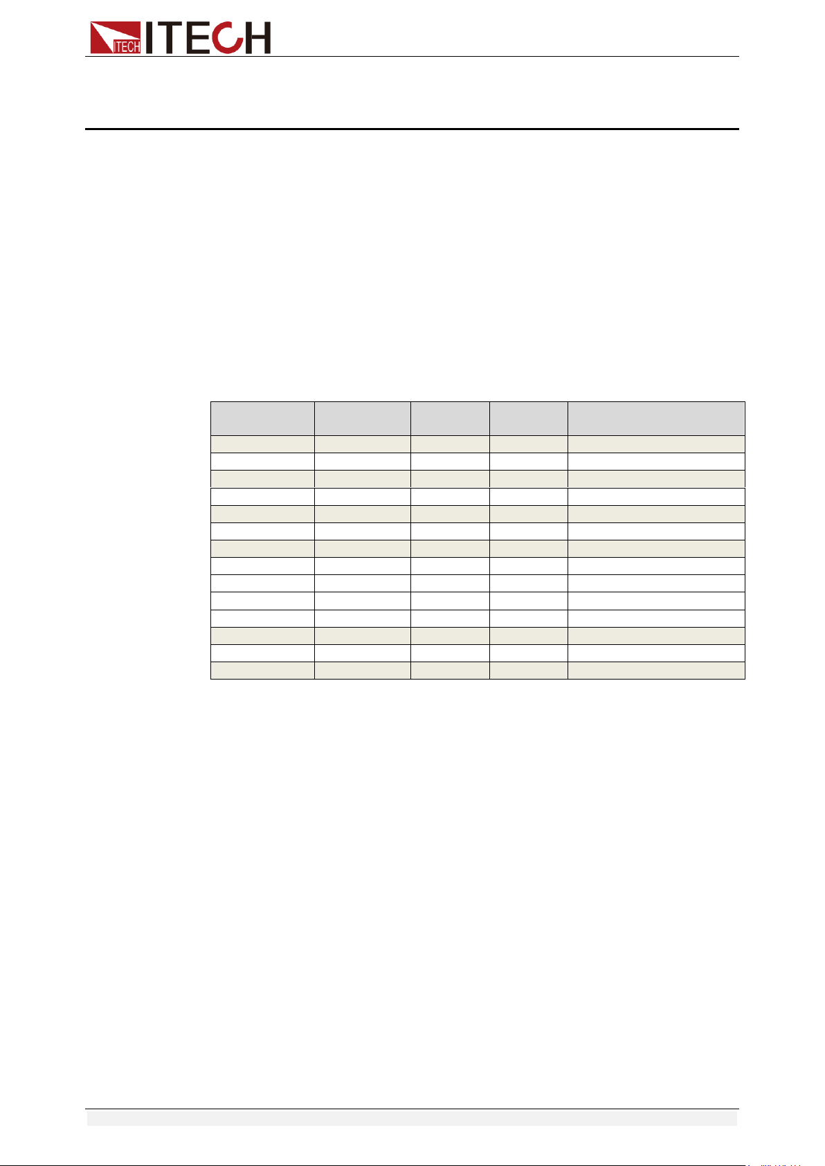
IT8511+/IT8511A+/IT8511B+/IT8512+/IT8512A+/IT8512B+/IT8512C+/IT8512H+/IT8513A+/IT85
13C+ Model
① Power switch
② Vacuum fluorescent display (VFD)
③ Compound key and the local switch key
④ Number key:
Set the parameters value, achieve the
menu’s function by key combination
⑤ Function key:
Set the operation mode
Control the input state: On/Off
⑥ Direction function
⑦ Rotary knob
⑧ Input terminal
IT8513B+/IT8514B+/IT8514C+ Model
① Power switch
② Vacuum fluorescent display (VFD)
③ Compound key and the local switch key
④ Number key:
Set the parameters value, achieve the
menu’s function by key combination
⑤ Function key:
Set the operation mode
Control the input state: On/Off
⑥ Direction function
⑦ Rotary knob
⑧ Input terminal
Quick Start
Copyright © Itech Electronic Co., Ltd. 14
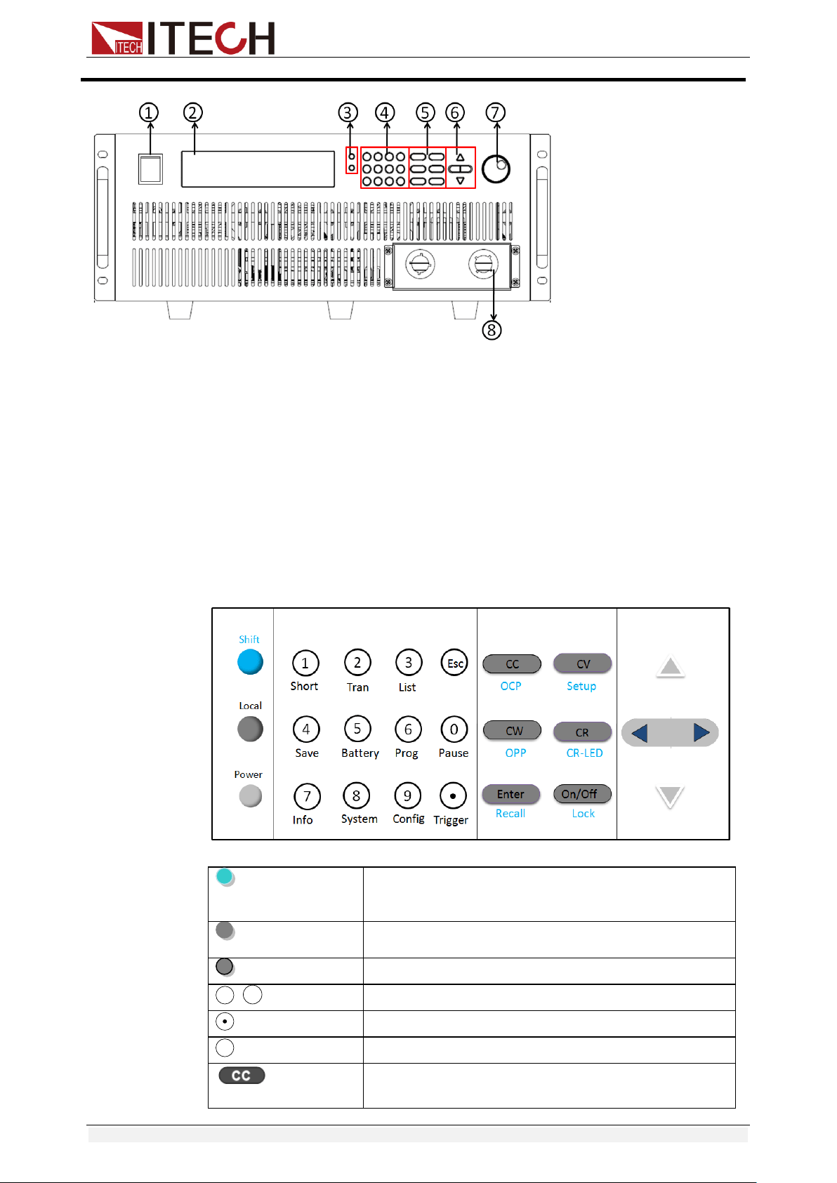
2.4 Front Panel Keys
( Blue-green)
The Shift composite button is used in combination
with other buttons to implement the functions
marked under these buttons.
(Gray)
Local button is used to switch local and remote
mode.
(Gray-white)
Power on/off button.
~
Enter the digits 0 to 9.
Decimal point
The escape button
Select the constant current mode and set the input
current value.
0
9
ESC
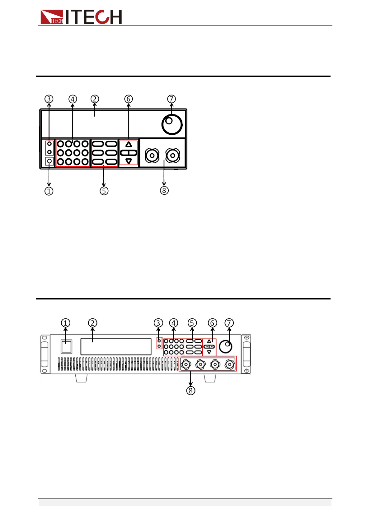
IT8516C+ Model
① Power switch
② Vacuum fluorescent display (VFD)
③ Compound key and the local switch key
④ Number key:
Set the parameters value, achieve the
menu’s function by key combination
⑤ Function key:
Set the operation mode
Control the input state: On/Off
⑥ Direction function
⑦ Rotary knob
⑧ Input terminal
Quick Start
Copyright © Itech Electronic Co., Ltd. 15
Select the constant voltage mode and set the input
voltage value.
Select the constant resistance mode and set the
input resistance value.
Select the constant power mode and set the input
power value.
Enter the selected value or setting.
Turn on or turn off the input of the load.
The scroll up key is used to select the menu item.
The scroll down key is used to select the menu item.
Move the left and right keys to adjust the cursor to
the specified position when setting the value.
2.5 Combination Keys
Press [Shift] button first and then other keys to achieve all kinds functions in
the following table.
[Shift]+[1] (Short)
Start or stop the short circuit test.
[Shift]+[2] (Tran)
Set the transient operation parameters.
[Shift]+[3] (List)
Set the LIST operation parameters.
[Shift]+[4] (Save)
Store the parameter value of the currently load.
Including: voltage, current and power values, and
so on.
[Shift]+[5] (Battery)
Battery test function.
[Shift]+[6] (Prog)
Automatic test function.
[Shift]+[7] (Info)
Displays the model number, version number, and
serial number of the electronic load.
[Shift]+[8] (System)
System menu setting
[Shift]+[9] (Config)
Configure menu setting
[Shift]+[0] (Pause)
Pressing this button during the running of the
automatic test indicates that the automatic test is
suspended.
[Shift]+[ ] (Trigger)
Cause an immediate trigger.
[Shift]+[CC] (OCP)
Enter OCP test function.
[Shift]+[CV] (Setup)
Set detailed parameters in CC/CV/CW/CR mode.
[Shift]+[CW] (OPP)
Enter OPP test function.
[Shift]+[CR] (CR-LED)
CR-LED function setting
[Shift]+[Enter] (Recall)
Recall the load parameter values that have been
stored. Includes: voltage, current and power
settings, and so on.
[Shift]+[On/Off] (Lock)
Key lock function
2.6 VFD Annunciators
OFF
The load input is off.
Error
An error has occurred.
CC
Constant current mode
Trig
Waiting for the trigger
signal.
Quick Start
Copyright © Itech Electronic Co., Ltd. 16
CV
Constant voltage mode
Sense
Remote sensing is turned
on.
CR
Constant resistance
mode
Prot
Protection function is
turned on.
CW
Constant power mode
Auto
Voltage range automatically
seleted function is turned
on.
Rmt
Instrument is in the
remote state.
Lock
The keyboard is locked.
Timer
LOAD ON timer is
turned on.
Shift
Shift button has been
pressed.
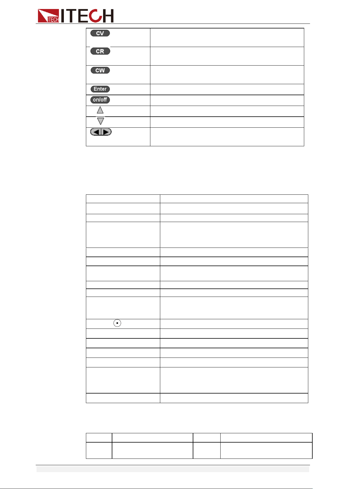
2.7 Rear Panel Introduction
IT8500+ series electronic load different models have different rear panels, the
rear panels and keyboards of different models are shown as below.
IT8511+/IT8511A+/ IT8511B+/IT8512+/ IT8512B+/IT8512C+/IT8512H+ Model
① Thermal window
② Line voltage selection switch
(110V/220V )
③ 3 pin IEC320 AC input connector
④ Current monitoring terminal
⑤ 9-Pin serial port interface connector
⑥ 4 pin trigger and remote sensing connector
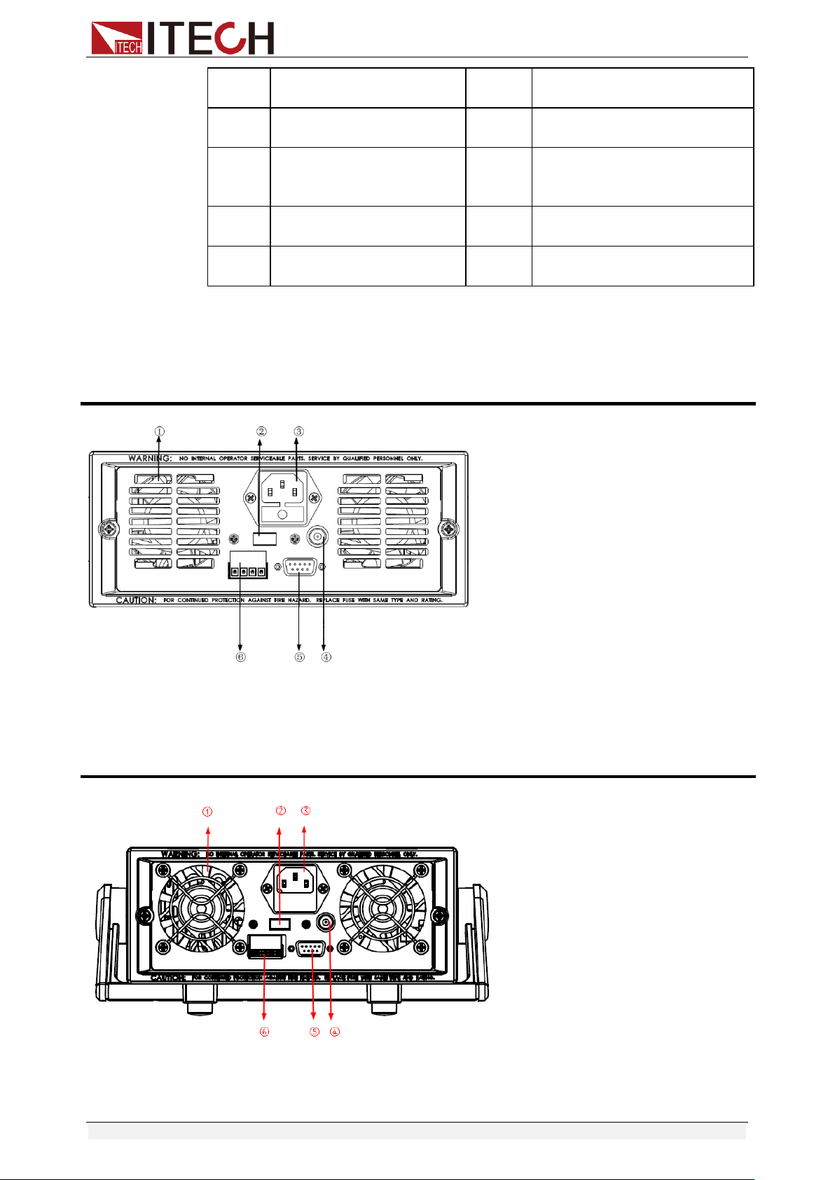
IT8513A+/IT8513C+ Model
①Thermal window
②Line voltage selection switch
(110V/220V )
④Current monitoring terminal
⑤9-Pin serial port interface connector
⑥4 pin trigger and remote sensing connector
Quick Start
Copyright © Itech Electronic Co., Ltd. 17
③3 pin IEC320 AC input connector
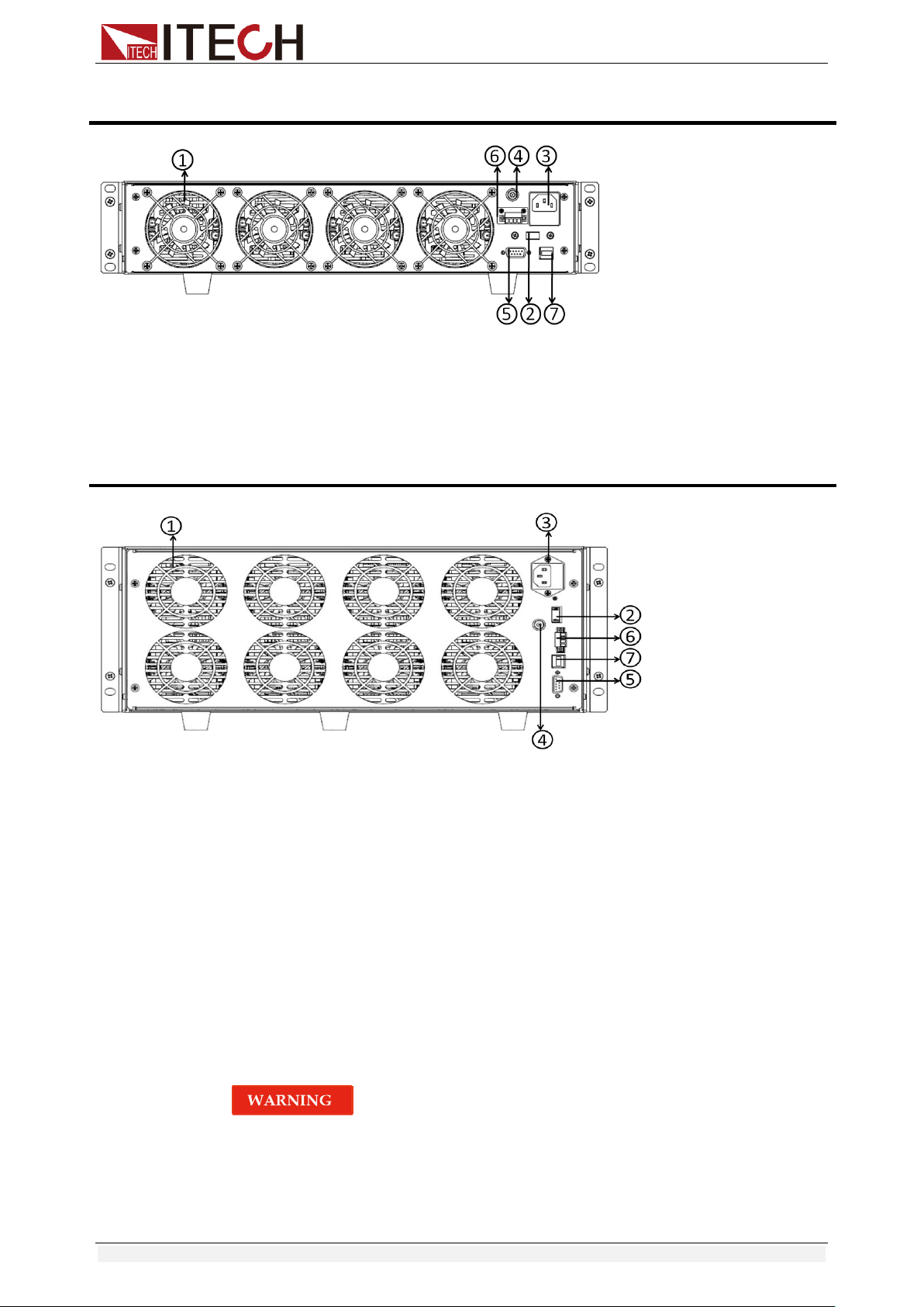
IT8513B+/IT8514B+/IT8514C+Model
① Thermal window
② Line voltage selection switch
(110V/220V)
③ 3 pin IEC320 AC input connector
④ Current monitoring terminal
⑤ RS232 communication cable interface
⑥ 4 pin trigger and remote sensing connector
⑦ USB communication cable interface
IT8516C+Model
① Thermal window
② Line voltage selection switch
(110V/220V)
③ 3 pin IEC320 AC input connector
④ Current monitoring terminal
⑤ RS232 communication cable interface
⑥ 4 pin trigger and remote sensing connector
⑦ USB communication cable interface
2.8 Power-on Selftest
A successful test process indicates that the instrument meets the factory
specifications and can be operated well.
Before operation, please confirm that you have fully understood the safety
instructions.
To avoid burning out, be sure to confirm that power voltage matches with
supply voltage.
Be sure to connect the main power socket to the power outlet of protective
grounding. Do not use terminal board without protective grounding. Before
operation, be sure that the power supply is well grounded.

Quick Start
Copyright © Itech Electronic Co., Ltd. 18
To avoid burning out, pay attention to marks of positive and negative
polarities before wiring.
Selftest steps
Normal selftest procedures:
1. Correctly connect the power cord. Press [ Power ] key to start up.
2. After selftest, VFD display information below.
Information description:
The first line display actual voltage and current value.
The second line display the actual power value and the setting
current/voltage/power/resistance value.
The third line display the input state/operation mode.
3. Press [Shift] + [7], VFD display products information. You can press
direction buttons to examine product’s model/SN/software version.
Error Information References
The following error information may occur when an error occurs during Power
On self-test:
If the EEPROM was damaged, the VFD will display “Eeprom Fail”.
If the latest operation data in EEPROM is lost, then VFD will display
“Config Data Lost”.
If the calibration data in EEPROM is lost, then VFD will display “Cal data
lost”.
If the system setting data in EEPROM is lost, the VFD will display “Eeprom
data lost”. Please press [Shift] + [4] and [0] to save after setting
parameters.
Exception handling
If the electronic load cannot start normally, please check and take measures by
reference to steps below.
1. Check whether the power line is correctly connected and confirm whether
the electronic load is powered.
Correct wiring of power line => 2
Incorrect wiring of power line => Re-connect the power line and check
whether the exception is removed.
2. Check whether the power in On. [Power] key is under “ ”(On)
status.
Yes => 3
No => Please check the [Power] key to start power and check whether the
exception is removed.
3. Check whether the power voltage setting of the electronic load is larger
than the power supply voltage. If the power voltage of the load is set to
220V and the supply voltage is 110V, the electronic load will not start.
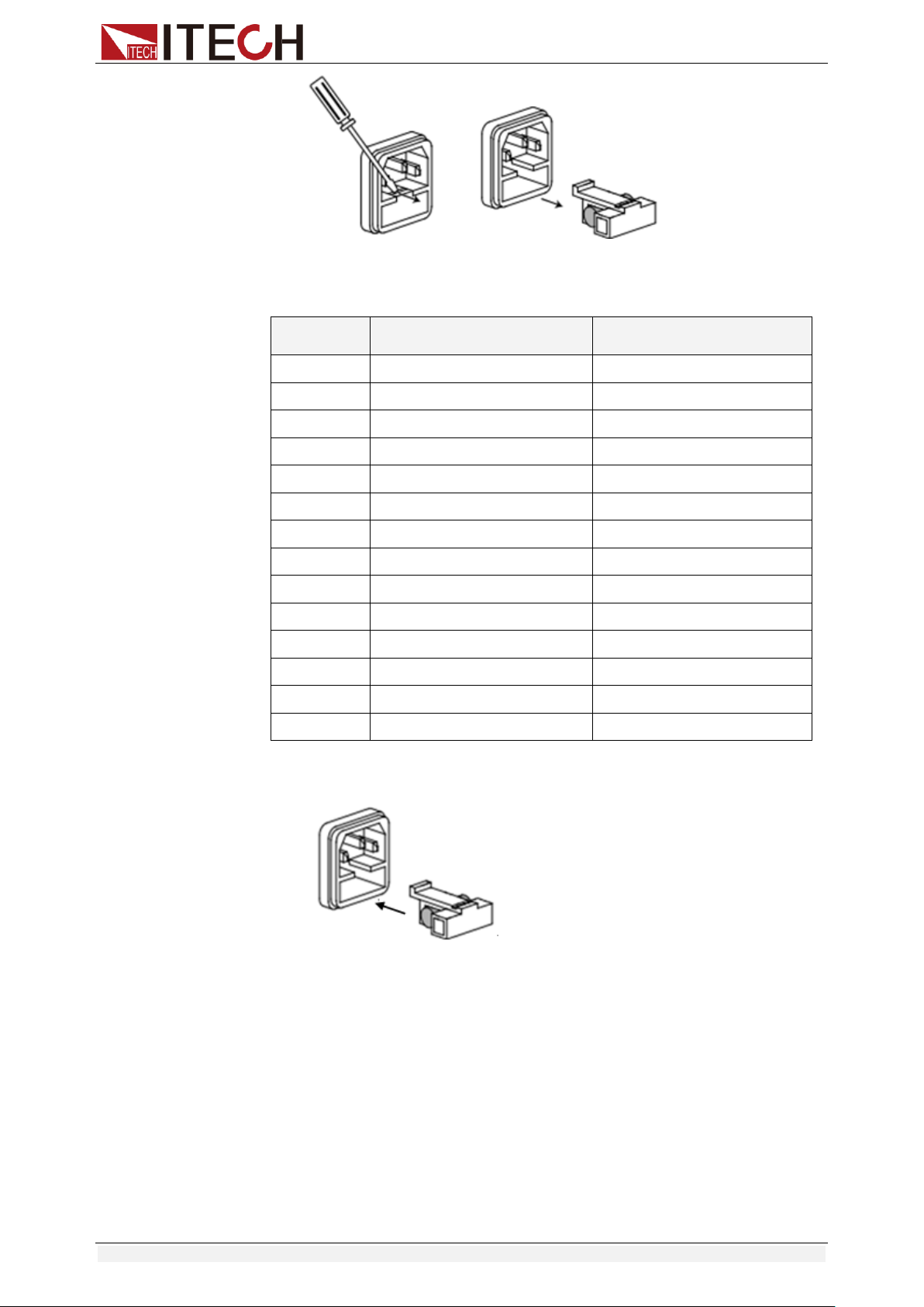
4. Check whether the fuse of electronic load is burned out.
If yes, change fuse. Detailed steps:
Pull out power line and take out the fuse box at power line jack with a
small screw driver. As shown below.
0.0000V 0.0000A
0.00W CC=0.000A
OFF CC Auto
Quick Start
Copyright © Itech Electronic Co., Ltd. 19
If the fuse is fused, replace it with a fuse of the same specification
according to the model. The fuse and model matching information is
shown in the table below.
Model
Fuse specification
(220VAC)
Fuse specification
(110VAC)
IT8511+
T0.5A 250V
T1.25A 250V
IT8511A+
T0.5A 250V
T1.25A 250V
IT8511B+
T0.5A 250V
T1.25A 250V
IT8512+
T0.5A 250V
T1.25A 250V
IT8512A+
T0.5A 250V
T1.25A 250V
IT8512B+
T0.5A 250V
T1.25A 250V
IT8512C+
T0.5A 250V
T1.25A 250V
IT8512H+
T0.5A 250V
T1.25A 250V
IT8513A+
T1.25A 250V
T2.5A 250V
IT8513B+
T1.25A 250V
T2.5A 250V
IT8513C+
T1.25A 250V
T2.5A 250V
IT8514B+
T1.25A 250V
T2.5A 250V
IT8514C+
T1.25A 250V
T2.5A 250V
IT8516C+
T2.5A 250V
T5A 250V
After replacement, install the fuse box back to original position, as
shown below.

Functions and Characteristics
Copyright © Itech Electronic Co., Ltd. 20
Chapter3 Functions and Characteristics
This chapter elaborates on the functions and characteristics of electronic loads.
Contents following sections:
Switching of local/remote operation modes
Constant-status operation mode
Input On/Off function
Keyboard locking function
Short - circuit analog function
System setup function
Triggering function
List mode
Test function
Save/Recall
VON function
Full protection function: OCP, OVP, OTP, OPP
Current monitoring function
Ripple function
3.1 Local Mode/Remote Mode
There are two types of control modes for IT8500+ series products: Local mode
and Remote mode.
Local mode: Use the buttons on the front panel of the electronic load to
perform related operations.
Remote mode: You can operate the electronic loads through PC via
communication cable (optional). In remote control mode, the keys on the
front panel cannot work except [Local] key. Customers could through
[Local] key to switch the control mode.
3.2 Operation Mode
There are four operation modes of IT8500+ series products:
Constant current mode (CC)
Constant voltage mode (CV)
Constant resistance mode (CR)
Constant power mode (CW)
3.2.1 Constant Current Mode (CC)
Select the function key CC, the load enters the constant current mode. In the
constant current mode, the electronic load consumes a constant current
regardless of whether the input voltage changes. The relationship between
voltage and current is shown in the figure below.

Functions and Characteristics
Copyright © Itech Electronic Co., Ltd. 21
Diagram 3-1 I-V curve in CC mode
There are two ways to set the current value:
In CC mode, rotate the Rotary knob.
In CC mode, input value through number keys directly, and press [Enter] to
confirm.
In CC mode, you can set the maximum operating current value.
Steps
1. Press [CC], and then press [Shift]+[CV](Setup) to enter into the
parameters setting page.
RANGE=30.000A
CC
2. Set the maximum working current value, and press [Enter] to confirm.
RANGE =10.000A
CC
3. Set the maximum working voltage value, and then press [Esc] to exit the
setup page.
Note
When you set the current range to low range, the resolution of current
will increase. Here, you can set only the voltage range, and other
parameter settings are used to edit the automatic test steps (described
below).
In CC mode, the user can also set the minimum value of the voltage, the
rising slope value of the current and the falling slope value of the current.
3.2.2 Constant Voltage Mode (CV)
In constant voltage mode, the electronic load will consume enough current to
maintain the input voltage at the set voltage.
Diagram 3-2 I-V curve in CV mode
Input current
Input voltage
I
V
Setting voltage
CV mode
Load
current
Input voltage
I
V
Setting current
CC mode

Functions and Characteristics
Copyright © Itech Electronic Co., Ltd. 22
There are two ways to change the voltage:
In CV mode, rotate Rotary knob.
In CV mode, input value through number keys directly, press [Enter] to
confirm.
Steps
1. Press [CV], and then press [Shift]+[CV](Setup) to enter into the
parameters setting page.
RANGE=120.00V
CV
2. Set the maximum working voltage value, and press [Enter] to confirm.
RANGE=10.00V
CV
3. Set the maximum working current value, and then press [Esc] to exit the
setup page.
HIGH=30.000A
CV
Note
Here, you can set only the current range, and other parameter settings are
used to edit the automatic test steps (described below).
In CV mode, the user can also set the minimum value of the current.
3.2.3 Constant Resistance Mode (CR)
In constant resistance mode, the DC load will behave as a fixed resistance
value. As shown below, the load linearly changes the current value with the
rising of input voltage.
Diagram 3-3 I-V curve in CR mode
There are two ways to set the resistance value:
In CR mode, rotate Rotary knob.
In CR mode, input value through number keys directly, press [Enter] to
confirm.
Steps
1. Press [CR], and then press [Shift]+[CV](Setup) to enter into the
parameters setting page.
RANGE=7500.0Ω
CR
2. Set the maximum working resistance value, and press [Enter] to confirm.
RANGE =2000Ω
CR
3. Set the maximum working voltage value, and then press [Esc] to exit the
Load
current
Input voltage
I
V
Slope is equal
To the setting
resistance
CR mode
Functions and Characteristics
Copyright © Itech Electronic Co., Ltd. 23
setup page.
HIGH=120.0V
CR
Note
In CR mode, the user can also set the minimum value of the voltage.
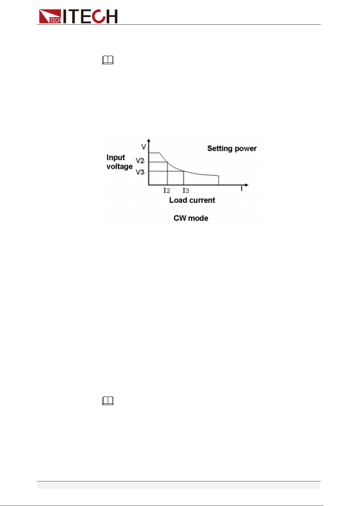
3.2.4 Constant Power Mode (CW)
In constant power mode, the electronic load will consume a constant power, as
shown in the figure below, if the input voltage rises, the input current will
decrease and the power P (= V * I) will remain at the setting value.
Diagram 3-4 I-V curve in CW mode
There are two ways to set the power value:
In CW mode, rotate Rotary knob.
In CW mode, input value through number keys directly, press [Enter] to
confirm.
Steps
1. Press [CW], and then press [Shift]+[CV](Setup) to enter into the
parameters setting page.
RANGE=150.00W
CW
2. Set the maximum working resistance value, and press [Enter] to confirm.
RANGE =100.00W
CW
3. Set the maximum working voltage value, and then press [Esc] to exit the
setup page.
HIGH=120.00V
CW
Note
In CW mode, the user can also set the minimum value of the voltage.
3.3 Input On/Off Control
[On/Off] button on the front panel is used to manually control input on or off.
[On/Off] button lighted indicates the load input is turned on, and the
real-time voltage and current information about the current loop is
displayed on the VFD screen.
Functions and Characteristics
Copyright © Itech Electronic Co., Ltd. 24
When the [On/Off] button light is off, the lower left of the VFD displays OFF,
indicating that the input is turned off.
3.4 Key Lock Function
Press the combined keys [Shift] +[On/Off] (Lock) to lock the front panel keys,
and VFD will display a Lock label. In this functional state, all keys except the
following keys are invalid. Pressing [Shift] +[On/Off] (Lock) again will cancel
the lock.
The [On/Off] button is available to toggle the input on and off.
The combined keys [Shift]+[7] (Info) is available to view the instrument
information. When viewing the instrument information, press [Esc] to exit.
3.5 Short-circuit Analog Function
Short circuit simulation and short circuit current measurement: you may press
[Shift] + [1] (Short) button to emulate a short state. It can be used to check
whether the tested instrument’s short protection is available.
Press [Shift] + [1] (Short) to switch the short circuit condition. The short-circuit
operation does not affect the current set value. When you press [Shift] + [1]
(Short) again, the electronic load returns to the original setting state.
In the short-circuit status, the actual consumed current value depends on the
operating mode and current range of the load. In CC, CW and CR modes, when
the current is within the maximum range, the short-circuit current is the input
current value. When the current exceeds the maximum range, the maximum
short-circuit current is 110% of the range. In the CV mode, the short circuit is
equivalent to setting the constant voltage value of the load to 0V.
3.6 System Menu (System)
Press [Shift] + [ 8 ] (system) to enter the system menu.
POWER-ON
POWER-ON
Power on state of instrument
RST(default)
Do not remember state in SAVE 0. Customer can save
an often used data in SAVE 0 to recall when power on
the DC load next time.
SAV0
Remember state in SAVE 0
BUZZER
BUZZER
Buzzer status setting
ON(default)
Enable audible beep when key is pressed.
OFF
No sound when key is pressed.
KNOB
KNOB
Real-time update function of knob
UPDATE(default)
The value modified with knob during operation will be
saved after input is off. For example, the DC load is set
to 1A by press [CC] and turned on the input. Then
increase the setting value to 2A with knob. When
customer turn off input, the setting value is still 2A.
OLD
As explained above, after the input is turned off, the
setting value is 1A instead of 2A.
TRIGGER
SOURCE
Set trigger mode
MANUAL(Def)
Triggered from the [Shift] + [.] key.
EXTERNAL
Triggered from a TTL high signal at the trigger
connector on rear panel
BUS
Triggered from a serial bus command 5AH
HOLD
Receiving a command 9DH
MEMORY
MEMORY
Use with the Recall button to call up
the stored parameters.
GROUP= 0
0: indicates1-10 groups;
Functions and Characteristics
Copyright © Itech Electronic Co., Ltd. 25
1: indicates 11-20 groups, and so on.
DISPLAY
DISP-TIMER
Timer function
ON
Enable timer function
OFF(default)
Disable timer function
RS-232
RS-232
4800_8N 1
Baud rate 4800, data bit 8, none parity, stop bit 1
9600_8N 1
Baud rate 9600, data bit 8, none parity, stop bit 1
19200_8N 1
Baud rate 19200, data bit 8, none parity, stop bit 1
38400_8N 1
Baud rate 38400, data bit 8, none parity, stop bit 1
PROTOCOL
SCPI
Select SCPI protocol
FRAME
Select FRAME protocol
ADDRESS
ADDRESS= 0
Set the instrument’s address(0~31)
RUNMODE
RUN
Running mode at power on
NORMAL
Normal mode
BATTERY
Default in battery test mode at power on
PROG_TEST
Default in automatic test mode at power on
OCP_TEST
Default in OCP test mode at power on
OPP_TEST
Default in OPP test mode at power on
TESTMOD
TESTMODE
Automatic test editing mode
NEW
IT8500+ specialized automatic test editing mode
IT8500
Compatible with IT8500 Automatic Test Edit Mode
DEFAULT
DEFAULT
Factory default setting
NO
Do not return instrument to factory default settings.
YES
Return instrument to factory default settings.
> DEFAULT
This option is used to restore all settings in the system menu to factory setting
values. Select “YES” and press [Enter] to restore to factory setting values.
Otherwise, the original system menu settings will remain unchanged.
The factory system menu is as follows:
Power-on
Rst
Buzzer
On
Knob
Update(default)
Trigger
Mannual
Memory
Group=0
Displ
Off (default)
>Power-on
When the power-on parameter is selected as RST, the input state when the
load is powered on is the factory state. If SAV0 is selected, the input state at
power-on of the load is the value of SAVE 0.
>Trigger
When using the transient and list function, you need to use the electronic load
Functions and Characteristics
Copyright © Itech Electronic Co., Ltd. 26
trigger function, you can choose Manual, External, Hold, or Bus as the trigger
mode. For the Manual option, the trigger signal is provided by composite keys
[Shift]+ [.](Trigger) in front panel.
>Buzzer
This item can set the key sound state. If in On mode, the electronic load will
issue beeper sound when you press any button. If in Off mode, the beeper will
not make a sound. The default set is in on mode.
>Knob
When the load input is turned on and the knob is turned to change the set
value, if the UPDATE option is selected, the load value is still the current
value after the load input is turned off;
If the OLD option is selected, the set value returns to the original value after
the load input is turned off.
>Display
If the option is set to On, the display of time 0.0000S will appear on the left
side of the VFD. Turn on the load input, the load time recording is started;
turned off the load input, the recording is stopped.
If the option is set to Off, the load time is not recorded.
3.7 Config Menu (Config)
Press [Shift]+ [ 9 ] (Config) to enter the configuration menu.
PROTECT
Max-P
Set hardware power protection
MAX POWER=150.00W
Set hardware OPP value
A-LIMIT
Set software current protecting state
ON
Enable software OCP function
A-LIM POIN=30.000A
Set the software OCP level
A-LIM DELAY=3S
Set the OCP delay time
OFF
Disable the software OCP function
P- LIMIT
Set software power protecting state.
P-LIM POIN=150.00W
Set the software OPP level.
P-LIM DELAY=3S
Set the OPP delay time.
TIMER
Set load on timer
ON
Enable load-on timer
LOAD-TIMER=10.0S
Set the load-on duration (0.1S~9999.9S)
OFF
Disable load-on timer
MEASURE
V-RANGE
Voltage range automatic switching
function
ON
Enable voltage auto range function
OFF
Disable voltage auto range function
FILTER
Set the filter parameter
FILTER COUNT = 2^14
Filter count set, ranges from 2 to 16.
Functions and Characteristics
Copyright © Itech Electronic Co., Ltd. 27
TIME-V1
TIME-VOLT1=0.000V
Set the start time to measure the voltage rise/fall time.
TIME-V2
TIME-VOLT2=120.00V
Set the end time to measure the voltage rise/fall time.
SENSE
REM- SENSE
Remote sense function
ON
Enable remote sense function
OFF
Disable remote sense function
VON
VON
Set the load’s VON point. For details,
see 3.12 VON Function.
LIVING
VON point living state
VON POINT = 0.10V
Set the VON value
LATCH
VON point latch state
VON POINT = 0.10V
Set the VON value
RESET
RESET
Reset the configuration menu.
NO
Do not reset the configuration menu.
YES
Reset the configuration menu.
>FILTER
This menu can set the number of sampled data during filtering. The average
value of the sampled data is taken during filtering. The setting range is 2~16.
>V-RANGE
This menu is used to control whether the voltage measurement range is
changed automatically.
On: Indicates the voltage measurement range will automatically change
between the high range and the low range.
Off: Indicates the voltage measurement range will not automatically
change.
>RESET
This option is used to restore all settings in the CONFIG MENU to factory
setting values. Select “YES” and press [Enter] to restore to factory setting
values. Otherwise, the original CONFIG MENU settings will remain unchanged.
3.8 Trigger Function
Triggering is used with the transient operation; list operation and auto-test
function. There are four types of triggers you can use for IT8500+ products.
Manual: An immediate trigger is created by pressing [Shift]+ [ ] (Trigger) on
the front panel.
External (TTL signal): On the rear panel of the electronic load, TRIG is the
trigger input terminal. When the external signal trigger mode is valid, after the
low pulse (>10uS) is applied to this terminal, the load will perform a trigger
operation. When the external trigger is selected, the positive and negative
terminals of TRIG generate the trigger signal, and the low pulse is valid. A
trigger-corresponding input can be used to change the set value (voltage,
current, resistance, etc.) to toggle between set points in the transient trigger
mode, or to generate pulses in the transient pulse mode.

Functions and Characteristics
Copyright © Itech Electronic Co., Ltd. 28
Bus: The instrument will be triggered if command 5AH is sent via the
communication interface.
Hold: The instrument will be triggered if command 9DH is sent via the
communication interface.
The steps to select a trigger source are as follows:
Steps
1. Press [Shift] + [8] (system) to enter the system menu.
POWER-ON BUZZER
2. Press the right key to move to TRIGGER, and press [Enter] to enter the
trigger source setting page.
SOURCE MANUAL
3. Select the trigger source and press [Enter].
MANUAL EXTERNAL BUS HOLD
4. Press [Esc] to exit the setting page.
3.9 LIST Operation
LIST mode provides an accurate, fast and low-cost way to complete any
complicated current change mode, which enables synchronization of internal or
external signals in multiple quasi-bit load precision tests.
When different trigger sources are selected, the LIST function will form a variety
of complex sequences by editing step value, pulse width and slope of each step
to meet complicated test requirements. LIST parameters comprise designation
of input list file, input step count (2-84 steps at maximum), step time (0.00005s
– 3600s) as well as setting value and slope of each step. The number of times
the List file is repeatedly executed ranges from 1 to 65535. The list file can be
stored in non-volatile RAM available for a quick output in case of usage. The
user can edit 7 groups of list files at maximum.
If the load operation mode is at List operation, the load will start List operation
when it receives a trigger signal and will stop when it complete or when it
receives another trigger signal.
You can press the keys on the front panel of the electronic load to edit the
sequence operation files, and trigger this sequence operation. Or you may
directly recall existing sequence operation files to trigger the sequence
operation. For example, when the DUT output voltage is 10V and the output
current is 3A, after editing the sequence operation files under Constant Current
(CC) mode, the steps for triggering sequence operation are as follows:
Trigger
10 2 3 4 5
List count=1 List count=2
List sequence
Functions and Characteristics
Copyright © Itech Electronic Co., Ltd. 29
Operation steps
1. Press [Shift]+[3] keys, the interface displayed as follows:
LIST OFF CALL EDI
2. Operate key and move to EDI. Press [Enter] key.
3. Set the CC range.
LIST RANGE=3A
4. Edit number of steps. Press [2] key to edit two steps. Press [Enter] key.
LIST STEP=2(2-84)
5. Edit current value in step 1 and press [Enter] key.
STEP 01 =1A
6. Edit slope in step 1 and press [Enter] key.
STEP 01 =0.1A/US
7. Edit time in step 1 and press [Enter] key.
STEP 01 =5S
8. Edit current value in step 2 and press [Enter] key.
STEP 02 =2A
9. Edit slope in step 2 and press [Enter] key.
STEP 02 =0.1A/US
10. Edit time in step 2 and press [Enter] key.
STEP 02 =5S
11. Edit repeat count and press [Enter] key.
REAPEAT =3
12. Save the edited file and press [Enter] key.
SAVE LIST =1(1-7)
13. Operate key and move to OFF. Press [Enter] key (In this case,
OFF changes to ON, and the VF status indicator Trig lamp of the VFD
display is illuminated). Press [ESC] key to exit setting.
LIST OFF CALL EDI
14. Press [On/Off] key to open input and press [Shift] + key (Trigger key).
15. Press [CC]/ [CV]/ [CR]/ [CW] key or any composite function key to exit List
test function.
For direct recall of existing List files and triggering of List operation, refer to
steps below:
Operation steps
1. Press [Shift] +3 keys.
LIST OFF CALL EDI
Ensure that OFF lamp flicks. If not, press [Enter] to change the lamp from
ON to OFF.
2. Press key to select CALL. And press [Enter] for confirmation.
3. Select edited file and press [Enter] for confirmation.
RECALL LIST = 1
Functions and Characteristics
Copyright © Itech Electronic Co., Ltd. 30
4. Operate key and move to OFF. Press [Enter] key (In this case,
OFF changes to ON, and the VF status indicator Trig lamp of the VFD
display is illuminated). Press [ESC] key to exit setting.
LIST OFF CALL EDI
5. Press [On/Off] key to open input and press [Shift] + key (Trigger key).
L1. 0. 0
Trig
3.10 Test Function
The transient test allows switching between two different load values. A
common application is to test the dynamic characteristics of DC source.
There are three different types of transient operation: continuous, pulse,
toggled.
Transient test parameters include:
Transient test mode
Transiently switched A and B values
Pulse width time (In PULSE mode)
Frequency
Duty cycle
Current rise and fall slope (CC mode specific parameters)
3.10.1 Transient Test Function
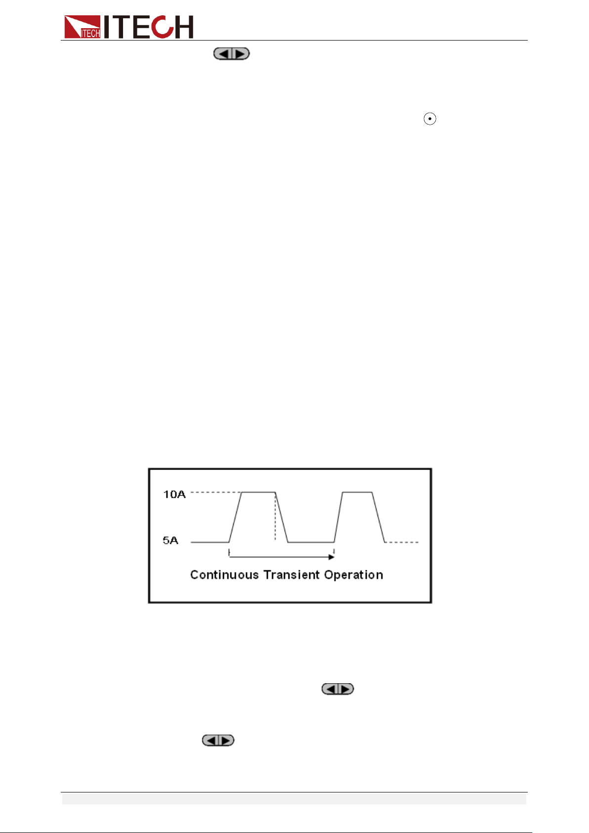
Continuous Mode
In continuous transient operation, the load is continuously switched between
two load values. An example is shown in the following figure:
Take CC mode as an example (other modes operate similarly). When the
measured instrument output voltage is 10V, current is 3A, and load current is
switched between 1A and 2A, the transient test parameters and steps are set
as follows:
1. Press [Shift]+[2] (Tran), move key to select ON, press [Enter] to
confirm.
TRAN ON OFF
2. Press to select transient operation mode as CONTINUOUS (the
indicator lamp Trig will be lighted).
MODE CONTINUOUS
PULSE TOGGLE
Functions and Characteristics
Copyright © Itech Electronic Co., Ltd. 31
3. Set the rising slope, press [Enter] to confirm.
UP=1A/uS
4. Set the descending slope, press [Enter] to confirm.
DOWN=1A/uS
5. Set level A, press [Enter] to confirm.
LEVEL A=1A
6. Set level B, press [Enter] to confirm.
LEVEL B=2A
7. Set the frequency, press [Enter] to confirm.
FREQ=50HZ
8. Set the duty factor, press [Enter] to confirm.
DUTY=98%(0.1%-99.9%)
9. Open the transient test function, maintain on the “on” selection, press
[Enter] to confirm.
TRAN ON OFF
10. Then the VFD will display TRAN and Trig.
10.0000V 0.0000A
0.00W TRAN. 0
Trig
11. Press [On/Off] to turn on the input function, and press [Shift]+[ ]
(Trigger) to trigger.
It can be seen that the A/B value is continuously switched, and the number
of running times is visible in the lower right corner.
Note
The maximum number of running times is 65535 and then reset to zero. The
running times reset does not affect the execution of the transient test.
12. Press any key of CC/CV/CR/CW or other composite function keys to exit
the transient test function. If you need to continue transient test parameter
setting and perform transient test, repeat steps 1 to 11.
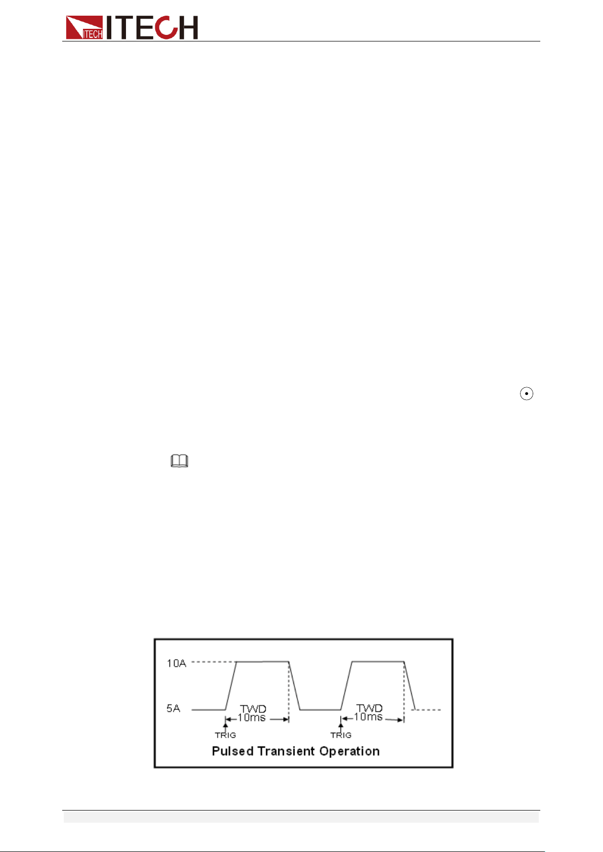
Pulse Mode
In pulse operation, the load operates at the A value that has been entered until
a trigger is received. At the trigger, the load switches to the B value and stays at
that level for the B timing value. Then the load switches back to the A value and
stays there until another trigger is received.
Take CC mode as an example (other modes operate similarly). When the
Functions and Characteristics
Copyright © Itech Electronic Co., Ltd. 32
measured instrument output voltage is 10V, current is 3A, and load current is
switched between 1A and 2A, the transient test parameters and steps are set
as follows:
1. Press [Shift]+[2] (Tran), move key to select ON, press [Enter] to
confirm.
TRAN ON OFF
2. Press to select transient operation mode as PULSE (the indicator
lamp Trig will be lighted).
3. Set the rising slope, press [Enter] to confirm.
4. Set the descending slope, press [Enter] to confirm.
5. Set level A, press [Enter] to confirm.
6. Set level B, press [Enter] to confirm.
7. Set the WIDTH, press [Enter] to confirm.
8. Open the transient test function, maintain on the “on” selection, press
[Enter] to confirm.
9. Then the VFD will display TRAN and Trig.
10. Press [On/Off] to turn on the input function, and press [Shift]+[ ]
(Trigger) to trigger.
11. Press any key of CC/CV/CR/CW or other composite function keys to exit
the transient test function. If you need to continue transient test parameter
setting and perform transient test, repeat steps 1 to 10.
Toggled Mode
In toggled transient operation, the load starts at the stored parameters for the
mode. When a trigger is received, the load switches to B value. When another
trigger is received, the load switches to the A level. It stays at the A value until
another trigger is received, at which point it switches to the B value. Here’s an
example:
Take CC mode as an example (other modes operate similarly). When the
measured instrument output voltage is 10V, current is 3A, and load current is
switched between 1A and 2A, the transient test parameters and steps are set
as follows:
1. Press [Shift]+[2] (Tran), move key to select ON, press [Enter] to
confirm.
TRAN ON OFF
2. Press to select transient operation mode as TOGGLE (the
indicator lamp Trig will be lighted).
10A
5A
TRG
TRG
Toggled Transient Operation

Functions and Characteristics
Copyright © Itech Electronic Co., Ltd. 33
3. Set the rising slope, press [Enter] to confirm.
4. Set the descending slope, press [Enter] to confirm.
5. Set level A, press [Enter] to confirm.
6. Set level B, press [Enter] to confirm.
7. Open the transient test function, maintain on the “on” selection, press
[Enter] to confirm.
8. Then the VFD will display TRAN and Trig.
9. Press [On/Off] to turn on the input function, and press [Shift]+[ ]
(Trigger) to trigger.
10. Press any key of CC/CV/CR/CW or other composite function keys to exit
the transient test function. If you need to continue transient test parameter
setting and perform transient test, repeat steps 1 to 9.
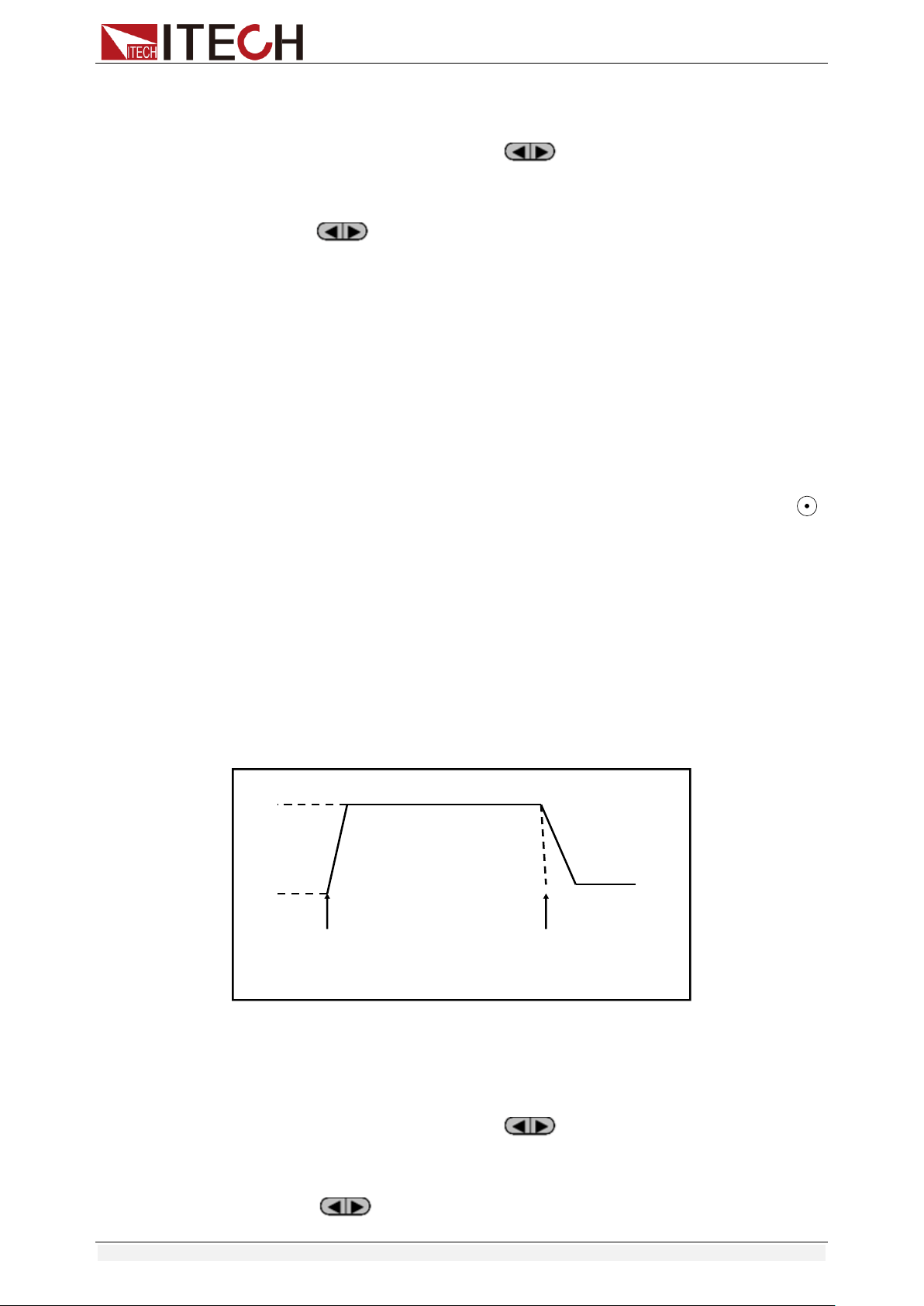
3.10.2 OCP Test Function
IT8500+ series electronic load supports the over current protection (OCP) test
function. In the OCP mode, when input voltage reaches VON point, the DC load
start to draw a current from the source after a delay time. The current value will
increase by a certain step size at regular intervals. Simultaneously, the DC load
will judge whether the input voltage exceeds OCP voltage you’ve set. If it is,
indicates that the OCP has not occurred, then repeat the current stepping
operation until the cutoff current is reached; if not, it indicates that the OCP has
occurred, and then check whether the current value is within the target range. If
it is within the range, PASS, otherwise FAULT. In other words, there are two
conditions for the end of the OCP current step, and if anyone is satisfied, the
stepping operation of the current will be ended.
Reach the set cutoff current.
The measured power supply voltage is less than the OCP voltage setting
value.
Press [Shift]+ [CC] (OCP) to enter the OCP operation page, and the related
parameters are described as follows.
No.
Parameter
Description
1
VON LEVEL=0.000V
Set the Von voltage value.
2
VON DELAY=0.00S
Set the Von voltage delay time.
After delay certain time, the
DC load starts to draw
current.
3
RANGE=3.000A
Set the working current range.
4
START=0.1000A
Set the initial current.
5
STEP=0.1000A
Set the step current.
6
STEP DEL=0.20S
Set delay time of each step.
7
END=2.0000A
Set the cutoff current.
8
OCP VOLT=2.000V
Set the OCP voltage.
9
MAX TRIP =1.5000A
Upper limit of OCP value.
10
MIN TRIP=0.9000A
Lower limit of OCP value
11
SAVE OCP FILE=1
Save OCP test file (1-10)

Functions and Characteristics
Copyright © Itech Electronic Co., Ltd. 34
Set the power on mode to the OCP test mode:
1. Press [Shift]+ [8] (system) to enter into system menu
0.0000V 0.000A
POWER-ON BUZZER
2. Press right key, select RUNMODE and confirm with [Enter] button.
0.0000V 0.000A
RUN NORMAL
3. Press to select OCP_TEST, press [Enter] to confirm.
The VFD displays the OCP test page.
0.0000V 0.000A
STOP 0.000A
4. After above steps, press [.] (Trigger) button to run OCP_TEST file.
Note
To exit the OCP mode, you can press the [Shift]+ [8] (System) buttons
to enter the system menu and set the RUNMODE to NORMAL.
3.10.3 OPP Test Function
IT8500+ series electronic load supports the over power protection (OPP) test
function. In the OPP mode, when input voltage reaches VON point, the DC load
start to draw a power from the source after a delay time. The power value will
increase by a certain step size at regular intervals. Simultaneously, the DC load
will judge whether the input voltage exceeds OPP voltage you’ve set. If it is,
indicates that the OPP has not occurred, then repeat the power stepping
operation until the cutoff power is reached; if not, it indicates that the OPP has
occurred, and then check whether the power value is within the target range. If
it is within the range, PASS, otherwise FAULT. In other words, there are two
conditions for the end of the OPP power step, and if anyone is satisfied, the
stepping operation of the power will be ended.
Reach the set cutoff power.
The measured power supply voltage is less than the OPP voltage setting
value.
Press [Shift]+ [CW] (OPP) to enter the OPP operation page, and the related
parameters are described as follows.
No.
Parameter
Description
1
VON LEVEL=0.000V
Set the Von voltage value.
2
VON DELAY=0.01S
Set the Von voltage delay time.
After delay certain time, the DC
load starts to draw power.
3
RANGE=5A
Set the working current range.
4
START =0.1W
Set the initial power.
5
STEP =1W
Set the step power.
6
STEP DEL=1S
Set delay time of each step.
7
END =12W
Set the cutoff power.
8
OPP VOLT=7V
Set the OPP voltage.
9
MAX TRIP =6.5W
Upper limit of OPP value.

Functions and Characteristics
Copyright © Itech Electronic Co., Ltd. 35
10
MIN TRIP =5.6W
Lower limit of OPP value
11
SAVE OPP FILE=1
Save OPP test file (1-10)
Set the power on mode to the OPP test mode:
1. Press [Shift]+ [8] (system) to enter into system menu
0.0000V 0.000A
POWER-ON BUZZER
2. Press right key, select RUNMODE and confirm with [Enter] button.
0.0000V 0.000A
RUN NORMAL
3. Press to select OPP_TEST, press [Enter] to confirm.
The VFD displays the OPP test page.
0.0000V 0.000A
STOP 0.00W
4. After above steps, press [.] (Trigger) button to run OPP_TEST file.
Note
To exit the OPP mode, you can press the [Shift]+ [8] (System) buttons
to enter the system menu and set the RUNMODE to NORMAL.
3.10.4 Battery Discharge Test
IT8500+ series electronic load supports the discharge test function of the
battery in CC/CW/CR mode.
The test mode should be set first, and then the discharge stop conditions.
There are three discharge stop conditions to be set for IT8500+ series products,
which are STOP VOLT, STOP CAP, and STOP TIMER. When any of the three
conditions is satisfied, the discharge is stopped and the electronic load is
automatically switched to the OFF state.
When user only need to do battery testing in one or two stop conditions, the
other conditions should be set to the specified value (STOP VOLT:0V; STOP
CAP:999.999AH; STOP TIMER:99999S).
For example, if the stop voltage is used as the termination condition and the
stop voltage is set, the stop capacity and the stop time must be set to the
maximum value (STOP CAP = 999.999AH, STOP TIMER=99999S).
When the system checks the discharging time or battery voltage or capacity is
equal to the setting stop value or under an insecurity state, the battery test will
be interrupted. The battery voltage, discharge time and discharged capability
are displayed on the VFD while testing.
Battery Test Data Storage
Before programming the battery test parameters, select RUNMODE as
NORMAL.
The following describes the operation steps by taking a discharge current of 7 A,
a cutoff voltage of 35 V, and a cutoff capacity of 11 AH as an example.
1. Press [Shift]+ [5] (Battery), set current range, and then press [Enter].
0.0000V 0.000A
RANGE =30.000A

Functions and Characteristics
Copyright © Itech Electronic Co., Ltd. 36
2. Set the discharge current, and press [Enter].
0.0000V 0.000A
CURRENT= 7.000A
3. Set the discharge stop voltage, and press [Enter].
0.0000V 0.000A
STOP VOLT= 35.00V
4. Set the discharge stop capability, and press [Enter].
0.0000V 0.000A
STOP CAP= 11.000AH
5. Set the discharge time, and press [Enter].
0.0000V 0.000A
STOP TIMER= 99999S
6. Save the battery test to specified file (1 – 10). After the file number is set,
press [Enter].
0.0000V 0.000A
SAVE BATT FILE 2
Set the power on state to the battery test. The steps are as follows.
1. Press [Shift]+ [8] (system) to enter into system menu.
0.0000V 0.000A
POWER-ON BUZZER
2. Press right key, select RUNMODE and confirm with [Enter] button.
0.0000V 0.000A
RUN NORMAL
3. Press to select BATTERY, press [Enter] to confirm.
The VFD displays the battery test page.
0.0000V 0.000A
0S 0.000AH
4. After above steps, press [.] (Trigger) button to run BATT_TEST file.
The discharging process will be terminated automatically when stop
conditions are reached.
Note
To exit the BATTERY mode, you can press the [Shift]+ [8] (System)
buttons to enter the system menu and set the RUNMODE to
NORMAL.
Battery Test Data Recalling
Applicable to IT8511B+/IT8512+/IT8512B+/IT8512C+/IT8512H+/IT8514C+
models. The steps are as follows:
1. In the BATTERY mode, press [Shift]+ [Enter] (Recall).
0.0000V 0.000A
RECALL BATTERY 1
2. Press the number keys to select the existing BATT_TEST file and press
[Enter].
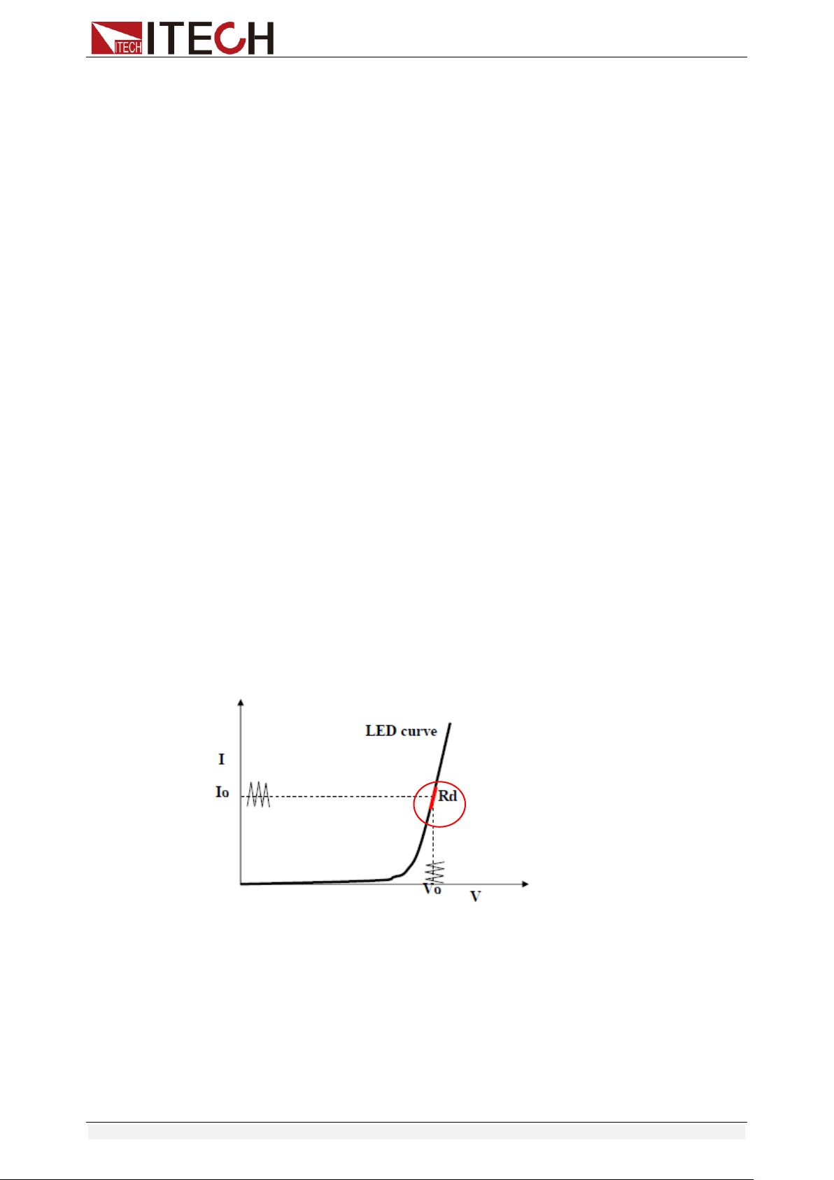
Functions and Characteristics
Copyright © Itech Electronic Co., Ltd. 37
Start Battery Test
In the BATTERY mode, you can press [.] (Trigger) to trigger the running of the
battery test. If the load does not detect the battery voltage, or if the stop
condition has been satisfied, the test will be stopped immediately and the input
of the load will be in OFF state.
During normal testing, the test time, the discharged capacity will be displayed
on the VFD in real time.
During the running of the battery test, the front panel can be locked to avoid
misoperation and interrupt the test process. If you need to lock the panel, press
[Shift]+[On/Off] (Lock) to lock all other keys except [Shift]+[On/Off] (Lock)
itself.
Stop Battery Test
Press [.](Trigger) or [Shift]+[.] (Trigger) or [ESC] to stop battery discharge test
(load input OFF).
Exit Battery Test
To exit the BATTERY mode, you can press the [Shift]+ [8] (System) buttons to
enter the system menu and set the RUNMODE to NORMAL.
3.10.5 CR-LED Test Function
With adding of diode break-over voltage setting in the IT8500+ series electronic
load under conventional CR mode, the electronic load only works when voltage
applied at its both ends is higher than the diode break-over voltage to give a
real simulation of diode working principle, i.e., the ripple current at real LED
test.
The I-V curve of LED is as shown below. Under conventional CR mode, the
electronic load only simulates the static working point of diode as shown in the
red circle of the following figure. It is unable to verify the dynamic characteristics
of LED under normal working conditions, and the status of accurate ripple
current.
Calculation method of Vd and R:
Definition:
Vo: constant working voltage of load LED of LED constant current source;
Io: output current of LED constant current source;
Vd: break-over voltage of diode (string);
R: constant resistance.
V-I curve of LED is as shown below.

Functions and Characteristics
Copyright © Itech Electronic Co., Ltd. 38
According to four parameters above and the V-I curve of LED, you can
calculate the value of R and Vd.
12
12
II
VV
R
RIVV
0od
NOTE
The value of V2, V1, I2 and I1 should be close to the static working point of LED as
shown in the red circle above.
Or you can roughly calculate the value of R and Vd with the following equation.
V
d
=V*0.8 R=0.2V/I
Where:
V: constant working voltage of load LED of LED constant current source;
I: output current of LED constant current source;
V
d
: break-over voltage of diode (string);
R: constant resistance.
In the following example, the output voltage of LED driver is 50V, verify that
whether the output current of LED is rated current 200mA: Vd=50V*0.8=40V
R=(0.2*50V)/0.2A=50Ω.
Setting CR-LED Mode
Example: LED driver specification
The output current is 200mA and the range of output voltage is from 45V to
62V.
Operating steps:
1. Start CR-LED function and set the Vd value.
1) Press [Shift] + [CR] keys to enter configuration menu.
2) Press Right Key and select ON. Press [Enter] key to set the Vd value.
(Set Vd=40V).
Select OFF to disenable CR-LED function, and then press [Enter] to
exit the setting menu.
3) Press the [Enter] key to save the settings.
2. Set CR mode
1) Press [CR] key and set corresponding constant resistance. (Set
CR=50Ω)
2) Press the [Enter] key to save the settings.
3. Press [On/Off] key to turn on load input.
Functions and Characteristics
Copyright © Itech Electronic Co., Ltd. 39
3.10.6 Measurement of Voltage Rise Time
The IT8500+ series electronic load is provided with special voltage rise/drop
time measurement function. This function gives a simple analog of voltage
rise/drop speed of oscilloscope test power.
Operation methods:
Set initial Voltage and Final Voltage
1. Press [Shift] + [9] keys to enter configuration menu. Press Right key.
Select Measure and press [Enter] key.
2. Press to select TIMEV1. Press [Enter] key. Press numeric keys
to set initial voltage value and press [Enter] key.
3. Press to select TIMEV2. Press [Enter] key. Press numeric keys
to set final voltage value and press [Enter] key.
4. Press [ESC] to exit setting.
Start timer function
5. Press [Shift] +[8] keys to enter system menu. Press Right key till
“DISPLAY” flicks and press [Enter] key.
6. Press key to select “On”. Start timer function and press [Enter]
key.
7. Press [ESC] to exit setting.
8. VFD second line will display time 0.0000S.
0.0001V 0.0002A
0.0000S I= 0.000A
OFF CC
Measurement of Rise Time
9. Connect DC power to be tested to the input terminal of the electronic load.
The power is set with a value that is higher than the set final voltage value.
Keep power output in OFF status.
10. Set a constant current value on the load and open the load input.
11. Open the power output.
12. The electronic load timer starts timing. After ending, time will keep stable,
which is rise time of voltage.
13. Turn off the power output. The electronic load VFD will display voltage drop
time.
3.11 Saving and Recalling Settings
We can save some often-used parameters in the non-volatile memory,
including working mode, voltage/current value and so on. IT8500plus series
provide 100 non-volatile registers.
They are divided into 10 Memory groups: Group0-9.You can set it in the system
menu.
Group0 means you can save and recall parameters in 0-10 registers.
Group1 means you can save and recall parameters in 11-20 registers.
Group2-Group9 can be concluded in the same manner.

Functions and Characteristics
Copyright © Itech Electronic Co., Ltd. 40
Save and Recall operation
For example: the instrument works in CC mode, setting value is 1A, memory
Group is 7. Save “CC 1A” in the 76th register and then recall.
Save
1. Set the parameters ok (CC 1A), and press [Enter].
2. Press [Shift] + [4] (Save) to save the instrument's settings to a register.
3. Enter number [7] and [6], indicates the settings is saved in the 6th register
in Group7.
4. Press [Enter], the setting is saved.
Recall
1. Press [Shift] + [8] (System) to enter the system setting page.
2. Press the right key to select MEMORY, and press [Enter].
3. Set the value of Group to 7, the interface displayed as follows.
MEMORY GROUP = 7
4. Press [Enter] to confirm the setting.
5. Press [Shift] + [Enter] (Recall) to execute the data recalling operation.
At this point, the [Enter] key light is on.
6. Enter number [6], indicates the data saved in the 6th register in Group7 is
recalled.
3.12 VON Function
When testing some power supply products with a slower voltage rise, if the
input of the electronic load is turned on first, and then the power is turned on,
the power supply may enter the protected state. Therefore, the user can set the
VON value, and when the power supply voltage is higher than this value, the
electronic load starts to load.
Please confirm whether you need to set the VON voltage. The VON voltage is
set to facilitate the user to limit the working voltage, and if you do not need to
set the VON voltage, do not set this value, otherwise it may result in unloading.
You can press [Shift]+[9] (Config) to enter the configuration menu to set the
VON voltage to control the ON/OFF state of the electronic load. The load has
two performance modes, Living and Latch. When Living is selected, it indicates
that the load works in following state; when Latch is selected, it indicates that
the load works in the load latched state.
If your instrument can not work normally, for example, set CC=1A, after turn on
the input while the current is still 0A instead of setting value 1A, then you should
check VON set firstly. If VON set is not 0V, then please modify to 0V. If the
minimum voltage supported by the instrument is not 0V, the setting menu will
be automatically set to the minimum value after pressing 0.
VON LIVING MODE
In Living mode, when power is applied to the DC load, the voltage must rise
above VON setting before the load draws current from the source. If the
voltage below VON setting on the load’s terminals, the load will turn off
input.
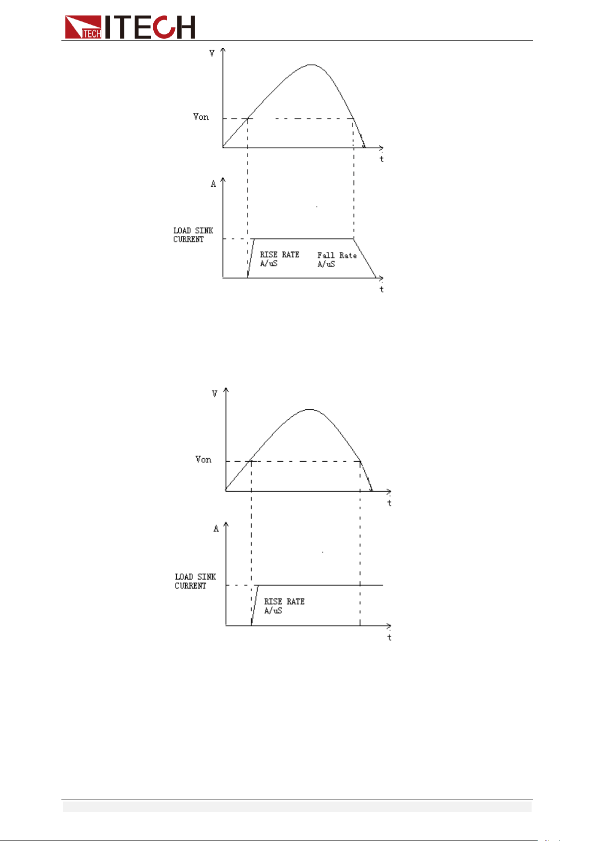
Functions and Characteristics
Copyright © Itech Electronic Co., Ltd. 41
VON LATCH MODE
In Latch mode, as before, the load will turn on only when the voltage
exceeds VON setting, but once on, it will now stay on, even if the voltage
drops to zero.
3.13 Protection Function
IT8500+ series electronic load supports the following protection function:
Over voltage protection (OVP)
Over current protection (OCP)
Over power protection (OPP)
Over temperature protection (OTP)

Functions and Characteristics
Copyright © Itech Electronic Co., Ltd. 42
If any of the above protections are activated, the electronic load enters the
corresponding self-protection mode, such as over temperature protection, the
load will generate an alarm and the input will automatically switch to the OFF
state. The VFD will display the OTP. You can clear the protection by pressing
any button on the front panel.
Over voltage protection (OVP)
If input voltage exceeds the voltage limit set by the user, the DC load will turn
the input OFF and the buzzer will sound. The display will show OVP.
Press any key on the front panel to exits OVP protection state.
Over current protection (OCP)
The DC load includes both hardware and software over current protection
features.
Hardware OCP: Maximum input current of the DC load will be limited at
about 110% of the current range, once the hardware OCP is activated, the
status register’s OC bit will be set; when the hardware OCP is removed,
the status register’s OC bit will be reset. Hardware over current protection
will not change the DC load’s On/Off state.
Software OCP: When the software OCP function is turned on, if the load
current exceeds the OCP set value and continues to exceed the set delay
time, the load will automatically turn OFF and the VFD will display OCP. At
the same time, the OC and PS bits in the status register will be set and they
will remain until they are reset. For related configuration items and
descriptions, see 3.7 Config Menu (Config).
Over power protection (OPP)
The DC load includes both hardware and software over power protection
features.
Hardware OPP: You can set the hardware OPP value of the load. The load
will be limited by the hardware to the power value. Hardware OPP does not
change the DC load’s On/Off state.
Software OPP: You can also set the software OPP value of the load.
For related configuration items and descriptions, see 3.7 Config Menu
(Config).
Over temperature protection (OTP)
When the electronic load internal power device temperature exceeds about
85°C, the electronic load activates the temperature protection mode. At this
time, the load input will be automatically turned OFF, and the VFD will display
the OTP. At the same time, the OT and PS bits in the status register will be set
and they will remain until they are reset.
3.14 Current Monitoring (I Monitor)
Current monitoring terminal will output 0-10V analog signal to
corresponding to 0 to full range of input current. You can connect an external
voltmeter or an oscilloscope to display the input current’s changing.
3.15 Ripple Function
IT8500+ series DC electronic loads have test ripple function. In the main
interface by pressing the up and down keys, you can read the VPK, APK value

Functions and Characteristics
Copyright © Itech Electronic Co., Ltd. 43
in the place where shows the power value. You can read ripple voltage and
ripple current by sending instructions also. See in IT8500+ programming
guide.

Automatic Test Function
Copyright © Itech Electronic Co., Ltd. 44
Chapter4 Automatic Test Function
This chapter introduces the IT8500+ series electronic load automatic test
operation method and process.
4.1 Introduction
The IT8500+ has two automatic test editing modes. One is the IT8500+ special
editing mode, which can save up to 10 groups of test files, and the other is
compatible with the IT8500 automatic test editing mode which can save up to
50 groups of test files. The test files in both modes can be recalled and tested
at any time. The test is simple and the button can be locked (press
[Shift]+[On/Off] (Lock)) to prevent accidental touches on the keyboard and
affect normal testing.
The electronic load automatically detects the change of the input voltage to
determine whether to start the test. After the automatic test start voltage (Start)
is set and the DUT is connected, when the load detects that the input voltage
rises from 0 to the Start voltage, the automatic test starts running without the
external trigger source or a trigger signal provided by manually operation.
When editing the automatic test mode, please avoid setting the last step to
short circuit, and avoid setting the input voltage of the last step to a value less
than the Start voltage, otherwise the automatic test will be executed cyclically.
4.2 Automatic Test Mode Switching
Press [Shift]+[8] (System) to enter the system menu, and press to
select the TESTMOD item. The VFD displays NEW and 8500. You can select
one of them and press [Enter] to confirm.
NEW
This is the automatic test mode for IT8500+ series electronic load.
This mode supports editing 10 groups of test files (file1 – file10), each
group contains 10 steps, and 10 groups of test files can be saved in
EEPROM. Test files can be linked to each other (such as linking file1 to
file2). Each test file contains the following parameters: load mode
(CC/CV/CR/CW, current rise and fall slope can be set in CC mode), load
value (Value), load time (Ton), unload time (Toff)), delay time (Tpf), upper
and lower limit of decision value (Low & High), trigger voltage (Start).
8500
This is the automatic test mode compatible with IT8500 series electronic
load.
This mode supports storing up to 50 groups of test files (file1-file50). Each
group contains 10 steps, and 50 groups of files can be saved in EEPROM.
Test files cannot be linked to each other. Each test file contains the
following parameters: load mode (CC/CV/CR/CW), load value (Value),
delay time (Delay), upper and lower limit value (Min & Max), trigger voltage
(Start).
The storage of test files under the two test modes is independent of each other,
that is, file1 in two modes is stored in different storage spaces.

Automatic Test Function
Copyright © Itech Electronic Co., Ltd. 45
Automated testing can be used to program, test, and show whether a test
passes or fails, which is very useful for the customer. The automatic test
operation consists of four steps: editing, saving, recalling, and running.
4.2.1 Test Mode for IT8500+
Note
The “Y” appears in the following edit to indicate the selected state, and press
the number key of the corresponding step again to deselect the state.
Operation Steps
1. Press [Shift]+[6] (Prog).
ACTIVE =0987654321
2. Press the number keys to select the step to be tested, for example,
ACTIVE =09876543YY, indicating that you have selected steps 1 and 2
and press [Enter] to confirm.
3. In these two steps, if you need to pause in step 2, you can press [2].
Otherwise, press [Enter] directly.
PAUSE =NNNNNNNNY1
4. In these two steps, if you need the short-circuit test in step 1, you can press
[1].
Otherwise, press [Enter] directly.
SHORT =NNNNNNNN2Y
5. Set Ton for the first step, if you want to load on 2S, press [2], and then
press [Enter] to confirm. Ton ranges from 0 to 60S.
SEQ01 ON =2S
6. Set Toff for the first step, if you want to load off 2S, press [2], and then
press [Enter] to confirm. Toff ranges from 0 to 60S.
SEQ01 OFF =2S
7. Set Tpf for the first step, if you want to delay 1S, press [1], and then press
[Enter] to confirm.
SEQ01 P/F =1S
8. Set Ton for the second step, if you want to load on 2S, press [2], and then
press [Enter] to confirm. Ton ranges from 0 to 60S.
SEQ02 ON =2S
9. Set Toff for the second step, if you want to load off 2S, press [2], and then
press [Enter] to confirm. Toff ranges from 0 to 60S.
SEQ02 OFF =2S
10. Set Tpf for the second step, if you want to delay 1S, press [1], and then
press [Enter] to confirm.
SEQ02 P/F =1S
11. Set the load voltage value and set it to 0 if not needed.
AUTO START= 0.500V
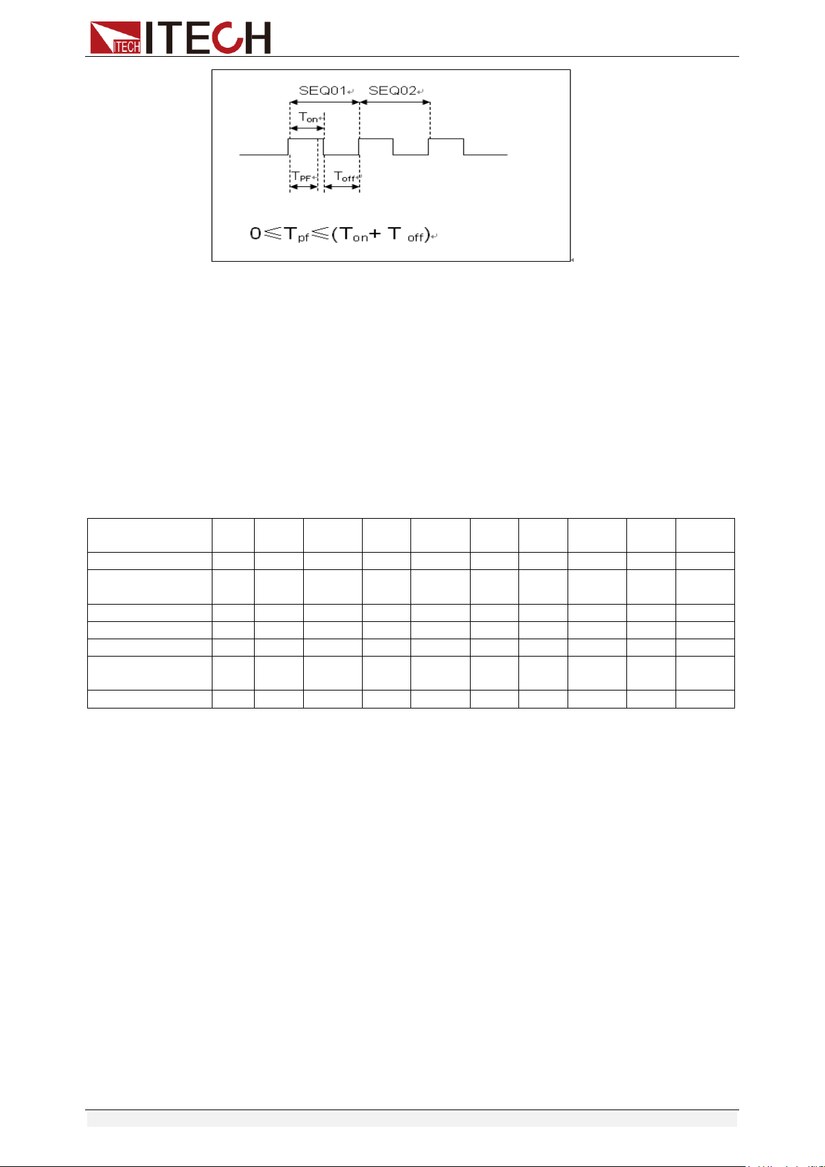
Automatic Test Function
Copyright © Itech Electronic Co., Ltd. 46
Tpf is the delay time for a step.
12. Set stop conditions: COMP means stop test when all the steps are
completed, FAILURE means stop test when the testing fails. Press [Enter]
key to confirm.
STOP COMP FAILURE
13. Select the test file to link if you’d like to. The linked file must be saved
before. 0 stands for not linking to other files. Press [Enter] key to confirm.
CHAIN PROGRAM=0 (0-10)
Automatic test file and single step storage correspondence table
PROGRAM 1
Sequence
1
2
3
4
5
6
7
8
9
10
Save Group
1
2
3
4
5
6
7
8
9
10
PROGRAM 2
Sequence
1
2
3
4
5
6
7
8
9
10
Save Group
11
12
13
14
15
16
17
18
19
20
:
:
PROGRAM 10
Sequence
1
2
3
4
5
6
7
8
9
10
Save Group
91
92
93
94
95
96
97
98
99
100
14. Save the edited files in EEPROM, you can save up to 10 groups of files, e.g.
please press [1] to save the edited file in group 1, and then press [Enter] to
confirm.
SAVE PROGRAM =1 (1-10)
The above is the automatic test structure. The automatic test single step
specific settings also need to be edited separately, so the design is to
facilitate the modification of the single step settings.
10.0000V 0.0000A
0.00W I=1.000A
15. Select an operation mode and then press [Shift]+[CV] (Setup) to set
related parameters.
16. Edit the automatic test single step, details refer to below procedure.
After all the steps are set, press [Shift]+[4] (save) to save.
Set the steps of a test file in the example
In the above step 16, assume that the first step is edited to CC mode, current
2A, the upper limit voltage value is 10V, the lower limit voltage value is 2V; the
second step is edited to CV mode, voltage 3V, upper limit current value 5A,
lower limit current value 0A. Save in the automatic test file 2.

Automatic Test Function
Copyright © Itech Electronic Co., Ltd. 47
The first step: CC mode, current 2A, the upper limit voltage value is 10V, and
the lower limit voltage value is 2V.
1. Press [CC], set the current to 2A, and then press [Shift]+[CV] (Setup) to
enter the setting interface.
RANGE=30.000A
CC
2. Set the maximum working current, and press [Enter] to confirm.
RANGE =2.000A
CC
3. Set the upper limit of voltage, press [Enter] to confirm.
HIGH=10.00V
CC
4. Set the lower limit of voltage, press [Enter] to confirm.
LOW=2.000V
CC
5. Set the rising slope of current, press [Enter] to confirm.
UP=1A/uS
CC
6. Set the descending slope of current, press [Enter] to confirm.
DOWN=1A/uS
CC
The parameter settings are complete.
10.0000V 0.000A
0.00W I=2.000A
7. Press [Shift] + [4] (Save) to enter the save settings interface. Press
numeric key [1] twice to save the current step as the first step of Program
2.
SAVE 11
The second step: CV mode, voltage 3V, the upper limit current value is 5A, and
the lower limit current value is 0A.
1. Press [CV], set the voltage to 3V, and then press [Shift]+[CV] (Setup) to
enter the setting interface.
RANGE=120.00V
2. Set the maximum working voltage, take 3V as example, and press [Enter]
to confirm.
RANGE=3.00V
3. Set the upper limit of current, press [Enter] to confirm.
HIGH=5.000A
4. Set the lower limit of current, press [Enter] to confirm.
LOW=0.0000A
The parameter settings are complete.
10.0000V 0.000A
0.00W V=3V
5. Press [Shift] + [4] (Save) to enter the save settings interface. Press
numeric keys [1] and [2] to save the current step as the second step of
Program 2.

Automatic Test Function
Copyright © Itech Electronic Co., Ltd. 48
SAVE 12
Note
The single-step parameter storage position is related to the number of
automatic test file storage group and the number of steps. If it is saved in
the first group, the single-step parameter storage position is consistent with
the number of steps. If it is saved in the second group, the single-step
parameter storage position is 1 merges the number of steps, for example,
the single-step 1, 2, and 3 are stored in 11, 12, and 13 respectively; if they
are stored in the third group, the single-step parameter storage position is 2
merges the number of steps, for example, the single-step 1, 2, and 3 are
saved in 21, 22, and 23, and so on.
Set the steps in CR/CW mode
Set the automatic test step in CW mode:
1. Press [CW], set the power value, and then press [Shift]+[CV] (Setup) to
enter the setting interface.
RANGE=150.00W
2. Set the maximum working power, and press [Enter] to confirm.
RANGE =20.00W
3. Set the upper limit of voltage, press [Enter] to confirm.
HIGH=120.00V
4. Set the lower limit of voltage, press [Enter] to confirm.
LOW=0.000V
5. The parameter settings are complete.
10.0000V 0.000A
0.00W W=1.00W
Set the automatic test step in CR mode:
1. Press [CR], set the resistance value, and then press [Shift]+[CV] (Setup)
to enter the setting interface.
RANGE=7500.0Ω
2. Set the maximum working resistance, and press [Enter] to confirm.
RANGE =2000Ω
3. Set the upper limit of voltage, press [Enter] to confirm.
HIGH=120.00V
4. Set the lower limit of voltage, press [Enter] to confirm.
LOW=0.000V
5. The parameter settings are complete.
10.0000V 0.000A
0.00W R=2.000Ω
4.2.2 Test Mode for IT8500
1. Press [Shift] + [6] (Prog) to set the maximum current value and press
[Enter] to confirm.
MAX CURR=30.00A

Automatic Test Function
Copyright © Itech Electronic Co., Ltd. 49
2. Set the maximum voltage value and press [Enter] to confirm.
MAX VOLT=120.00V
3. Set the maximum power value and press [Enter] to confirm.
MAX POWER=300.00W
4. Set the number of test steps, up to 10 steps, press [Enter] to confirm.
TEST STEP=10
5. Set the mode of the step, move the left and right cursors, when the mode
option flashes, it indicates that the mode is selected, press [Enter] to
confirm (such as select CC mode).
MODE CC CV CW CR
6. Set the current value and press [Enter] to confirm.
S01 CURR=**A
7. Set whether the step is short-circuited, move the left and right cursors to
select, and press [Enter] to confirm.
SHORT ON OFF
8. Set the type of value to be tested, move the left and right cursors to select,
and press [Enter] to confirm (such as selecting the value of the test as the
current value).
READBACK V A W
9. Set the upper limit current value and press [Enter] to confirm.
S01 MAX=**A
10. Set the lower limit current value and press [Enter] to confirm.
S01 MIN=**A
11. Set the delay time. That is, the test value is read after the input is set for a
certain period of time, and is used to test after the output is stable. The
delay range is 0.1~25 seconds.
S01 DELAY=**(S)
12. Repeat steps 5 through 11 to set the automatic test parameters for the next
steps.
13. Set the load voltage value. If no setting is required, set it to 0 and press
[Enter] to confirm.
START= **V
14. Set the test stop conditions. COMP means that the test stops after all tests
are completed, and FAILURE indicates that the test stops when an error
occurs.
STOP COMP FAILURE
15. Save the programmed file to EEPROM. You can save 50 groups of files. If
you want to put the edited file in the first group, press 1 and press [Enter]
to confirm.
SAVE PROGRAM =1 (1-50)
Note
In the process of editing the automatic test file, if an editing error
occurs, you can press the up arrow key to return to the previous step
to make changes without exiting the entire editing interface of the test
file.

Automatic Test Function
Copyright © Itech Electronic Co., Ltd. 50
Set the power-on state to automatic test
1. Press [Shift] + [8] (System) to enter the system menu.
POWER-ON BUZZER
2. Press the right key to the RUNMODE, and press [Enter].
RUNMODE DEFAULT
3. Press the left or right key to select PROG_TEST and press [Enter], the
menu will return to RUNMODE.
RUN <PROG_TEST
4. Press [Esc] to exit.
P01
Note
To exit the automatic test mode, press [Shift] + [8] (System) to enter
the system menu and select RUNMODE as NORMAL.
Recall the test file to run
The following method can quickly recall the existing test file from the EEPROM
and test it after the instrument is powered on.
Operate in automatic test mode:
1. Press [Shift] + [Enter] (Recall).
0.0000V 0.000A
RECALL PROGRAM=1 (0~10)
2. Press the number keys to select the group and press [Enter].
0.0000V 0.000A
P01
3. If the start voltage (Start) is set to 0 during the editing process, press [Shift]
+ [.] (Trigger) to trigger.
If the start voltage (Start) is set to a non-zero value, connect the DUT to
start the test. The automatic test step will be displayed on the VFD and
FAULT or PASS will be displayed after the test is over.
0.0000V 0.000A
P01-01 2.100A
Note
Press [Shift] + [0] (Pause) to stop running the automatic test. Press
to continue testing.
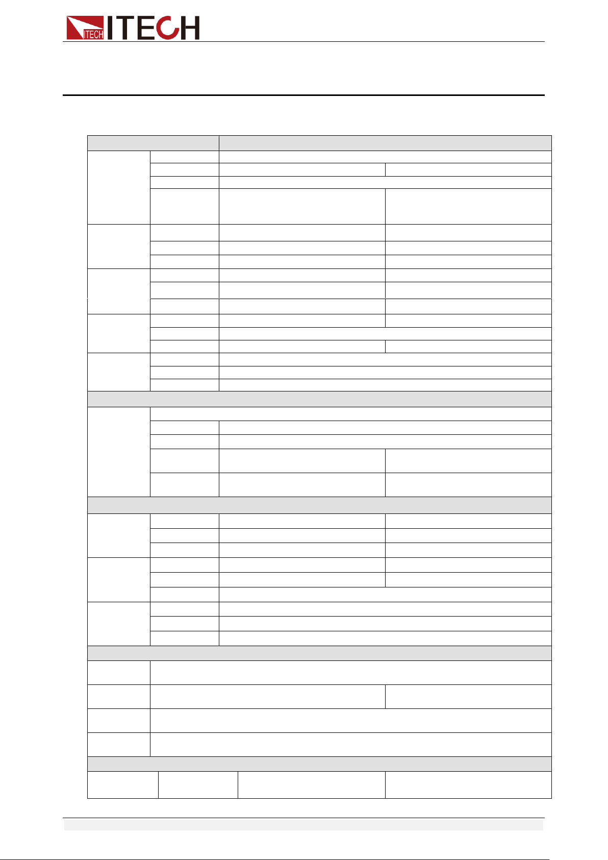
Specifications
Copyright © Itech Electronic Co., Ltd. 51
Chapter5 Specifications
Specifications
Model
IT8511+
Rated value
( 0~40 ℃)
Input voltage
0~120V
Input current
0~3A
0~30A
Input power
150W
Minimum
operation
value
0.14V at 3A
1.4V at 30A
CV mode
Range
0.1~18V
0.1~120V
Resolution
1mV
10mV
Accuracy
±(0.05%+0.02%FS)
±(0.05%+0.025%FS)
CC mode
Range
0~3A
0~30A
Resolution
0.1mA
1mA
Accuracy
±(0.05%+0.05%FS)
±(0.05%+0.05%FS)
CR mode
*1
Range
0.05Ω~10Ω
10Ω~7.5KΩ
Resolution
16bit
Accuracy
0.01%+0.08S *2
0.01%+0.0008S
CP mode
*3
Range
150W
Resolution
10mW
Accuracy
±(0.1%+0.2%FS)
Dynamic mode
Dynamic
mode
CC mode
T1&T2
20uS~3600S /Res:1 uS
Accuracy
2uS±100ppm
Rising/Falling
slope *4
0.0001~0.2A/uS
0.001~1.5A/uS
Minimum rise
time *5
≒10uS
≒10uS
Measuring range
Readback
voltage
Range
0~18V
0~120V
Resolution
0.1 mV
1 mV
Accuracy
±(0.025%+0.025%FS)
±(0.025%+0.025%FS)
Readback
current
Range
0~3A
0~30A
Resolution
0.1mA
1mA
Accuracy
±(0.05%+0.05%FS)
Readback
power
Range
150W
Resolution
10mW
Accuracy
±(0.1%+0.2%FS)
Protection range
OPP
Protection
≒160W
OCP
Protection
≒3.3A
≒33A
OVP
Protection
≒125V
OTP
Protection
≒85℃
Specification
Short
Current( CC )
≒3.3/3A
≒33/30A

Specifications
Copyright © Itech Electronic Co., Ltd. 52
Voltage( CV )
0V
0V
Resistance( CR
)
≒45mΩ
≒45mΩ
Input
Impendance
150KΩ
Dimension
214.5mm*88.2mm*354.6mm
*1 The voltage/current input is no less than 10% FS
*2 The scope of read-back resistance is: (1/(1/R+(1/R)*0.01%+0.08),1/(1/R-(1/R)*0.01%-0.08))
*3 The voltage/current input is no less than 10% FS
*4 Ascending/descending slope: 10%-90% current ascending slope from 0 to maximum current.
*5 Minimum rise time: 10%-90% current rise time
Model
IT8512+
Rated value
( 0~40 ℃)
Input voltage
0~120V
Input current
0~3A
0~30A
Input power
300W
Minimum
operation
value
0.12V at 3A
1.2V at 30A
CV mode
Range
0.1~18V
0.1~120V
Resolution
1mV
10mV
Accuracy
±(0.05%+0.02%FS)
±(0.05%+0.025%FS)
CC mode
Range
0~3A
0~30A
Resolution
0.1mA
1mA
Accuracy
±(0.05%+0.05%FS)
±(0.05%+0.05%FS)
CR mode
*1
Range
0.05Ω~10Ω
10Ω~7.5KΩ
Resolution
16bit
Accuracy
0.01%+0.08S *2
0.01%+0.0008S
CP mode
*3
Range
300W
Resolution
10mW
Accuracy
±(0.1%+0.2%FS)
Dynamic mode
Dynamic
mode
CC mode
T1&T2
20uS~3600S /Res:1 uS
Accuracy
2uS±100ppm
Rising/Falling
slope *4
0.0001~0.2A/uS
0.001~1.5A/uS
Minimum rise
time *5
≒10uS
≒10uS
Measuring range
Readback
voltage
Range
0~18V
0~120V
Resolution
0.1 mV
1 mV
Accuracy
±(0.025%+0.025%FS)
±(0.025%+0.025%FS)
Readback
current
Range
0~3A
0~30A
Resolution
0.1mA
1mA
Accuracy
±(0.05%+0.05%FS)
Readback
power
Range
300W
Resolution
10mW
Accuracy
±(0.1%+0.2%FS)
Protection range
OPP
Protection
≒320W
OCP
Protection
≒3.3A
≒33A
OVP
Protection
≒125V
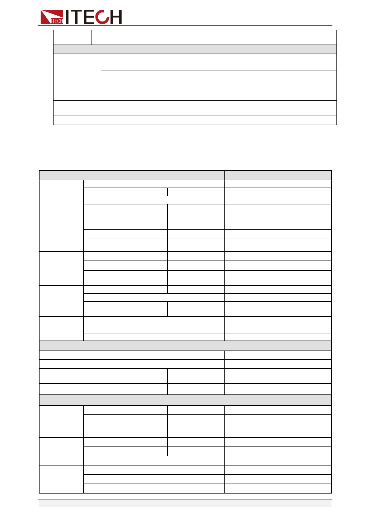
Specifications
Copyright © Itech Electronic Co., Ltd. 53
OTP
Protection
≒85℃
Specification
Short
Current( CC )
≒3.3/3A
≒33/30A
Voltage( CV )
0V
0V
Resistance(
CR )
≒40mΩ
≒40mΩ
Input
Impendance
150KΩ
Dimension
214.5mm*88.2mm*354.6mm
*1 The voltage/current input is no less than 10% FS
*2 The scope of read-back resistance is: (1/(1/R+(1/R)*0.01%+0.08),1/(1/R-(1/R)*0.01%-0.08))
*3 The voltage/current input is no less than 10% FS
*4 Ascending/descending slope: 10%-90% current ascending slope from 0 to maximum current.
*5 Minimum rise time: 10%-90% current rise time
Model
IT8511A+
IT8512A+
Rated value
( 0~40 ℃)
Input voltage
0~150V
0~150V
Input current
0~3A
0~30A
0~3A
0~30A
Input power
150W
300W
Minimum
operation value
0.25V at 3A
2.5V at 30A
0.14V at 3A
1.4V at 30A
CV mode
Range
0.1~18V
0.1~150V
0.1~18V
0.1~150V
Resolution
1mV
10mV
1mV
10mV
Accuracy
±(0.05%+0.0
2%FS)
±(0.05%+0.025%FS)
±(0.05%+0.02%FS)
±(0.05%+0.025%F
S)
CC mode
Range
0~3A
0~30A
0~3A
0~30A
Resolution
0.1mA
1mA
0.1mA
1mA
Accuracy
±(0.05%+0.
05%FS)
±(0.05%+0.05%FS)
±(0.05%+0.05%FS)
±(0.05%+0.05%
FS)
CR mode
*1
Range
0.05Ω~10Ω
10Ω~7.5KΩ
0.05Ω~10Ω
10Ω~7.5KΩ
Resolution
16bit
16bit
Accuracy
0.01%+0.08
S *2
0.01%+0.0008S
0.01%+0.08S *2
0.01%+0.0008S
CP mode
*3
Range
150W
300W
Resolution
10mW
10mW
Accuracy
±( 0.1%+0.1%FS )
±( 0.1%+0.1%FS )
Dynamic mode( CC mode )
T1&T2
20uS~3600S /Res:1 uS
20uS~3600S /Res:1 uS
Accuracy
2uS±100ppm
2uS±100ppm
Rising/Falling slope *4
0.0001~0.2
A/uS
0.001~1.5A/uS
0.0001~0.2A/uS
0.001~1.5A/uS
Minimum rise time *5
≒10uS
≒10uS
≒10uS
≒10uS
Measuring range
Readback
voltage
Range
0~18V
0~150V
0~18V
0~150V
Resolution
0.1 mV
1 mV
0.1 mV
1 mV
Accuracy
±(0.025%+0.
025%FS)
±(0.025%+0.025%FS)
±(0.025%+0.025%FS)
±(0.025%+0.025%
FS)
Readback
current
Range
0~3A
0~30A
0~3A
0~30A
Resolution
0.1mA
1mA
0.1mA
1mA
Accuracy
±(0.05%+0.05%FS)
±(0.05%+0.05%FS)
Readback
power
Range
150W
300W
Resolution
10mW
10mW
Accuracy
±(0.1%+0.1%FS)
±(0.1%+0.1%FS)
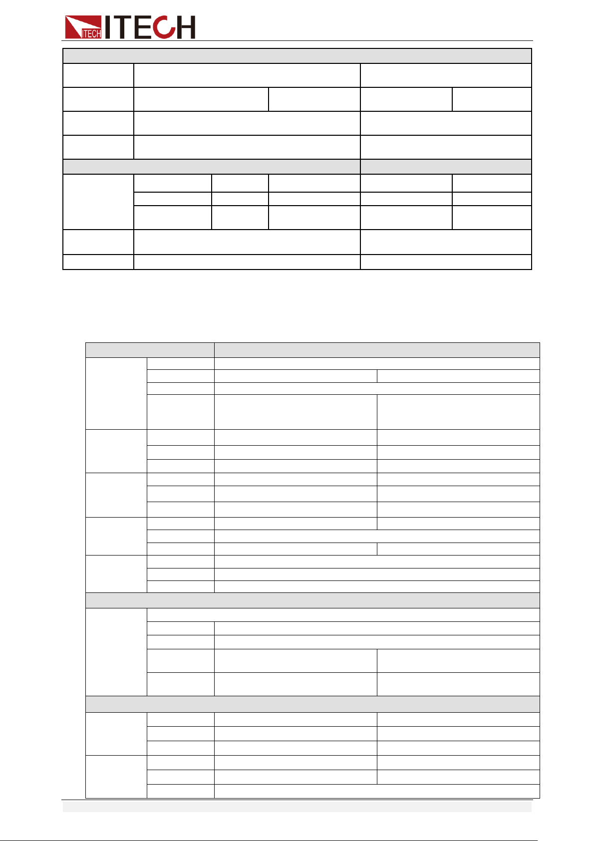
Specifications
Copyright © Itech Electronic Co., Ltd. 54
Protection range
OPP
Protection
≒160W
≒320W
OCP
Protection
≒3.3A
≒33A
≒3.3A
≒33A
OVP
Protection
≒160V
≒160V
OTP
Protection
≒85℃
≒85℃
Specification
Short
Current( CC )
≒3.3/3A
≒33/30A
≒3.3/3A
≒33/30A
Voltage( CV )
0V
0V
0V
0V
Resistance( CR
)
≒80mΩ
≒80mΩ
≒40mΩ
≒40mΩ
Input
Impendance
150KΩ
150KΩ
Dimension
214.5mm*88.2mm*354.6mm
214.5mm*88.2mm*354.6mm
*1 The voltage/current input is no less than 10% FS
*2 The scope of read-back resistance is: (1/(1/R+(1/R)*0.01%+0.08),1/(1/R-(1/R)*0.01%-0.08))
*3 The voltage/current input is no less than 10% FS
*4 Ascending/descending slope: 10%-90% current ascending slope from 0 to maximum current.
*5 Minimum rise time: 10%-90% current rise time
Model
IT8511B+
Rated value
( 0~40 ℃)
Input voltage
0~500V
Input current
0~3A
0~10A
Input power
150W
Minimum
operation
value
1.2V at 3A
4V at 10A
CV mode
Range
0.1~50V
0.1~500V
Resolution
1mV
10mV
Accuracy
±(0.05%+0.05%FS)
±(0.05%+0.05%FS)
CC mode
Range
0~3A
0~10A
Resolution
0.1mA
1mA
Accuracy
±(0.05%+0.05%FS)
±(0.05%+0.05%FS)
CR mode
*1
Range
0.5Ω~10Ω
10Ω~7.5KΩ
Resolution
16bit
Accuracy
0.01%+0.08S *2
0.01%+0.0008S
CP mode
*3
Range
150W
Resolution
10mW
Accuracy
0.1%+0.2%FS
Dynamic mode
Dynamic
mode
CC mode
T1&T2
20uS~3600S /Res:1 uS
Accuracy
2uS±100ppm
Rising/Falling
slope *4
0.0001~0.2A/uS
0.001~0.8A/uS
Minimum rise
time *5
≒10uS
≒10uS
Measuring range
Readback
voltage
Range
0~50V
0~500V
Resolution
1 mV
10 mV
Accuracy
±(0.025%+0.025%FS)
±(0.025%+0.025%FS)
Readback
current
Range
0~3A
0~10A
Resolution
0.1mA
1mA
Accuracy
±(0.05%+0.05%FS)
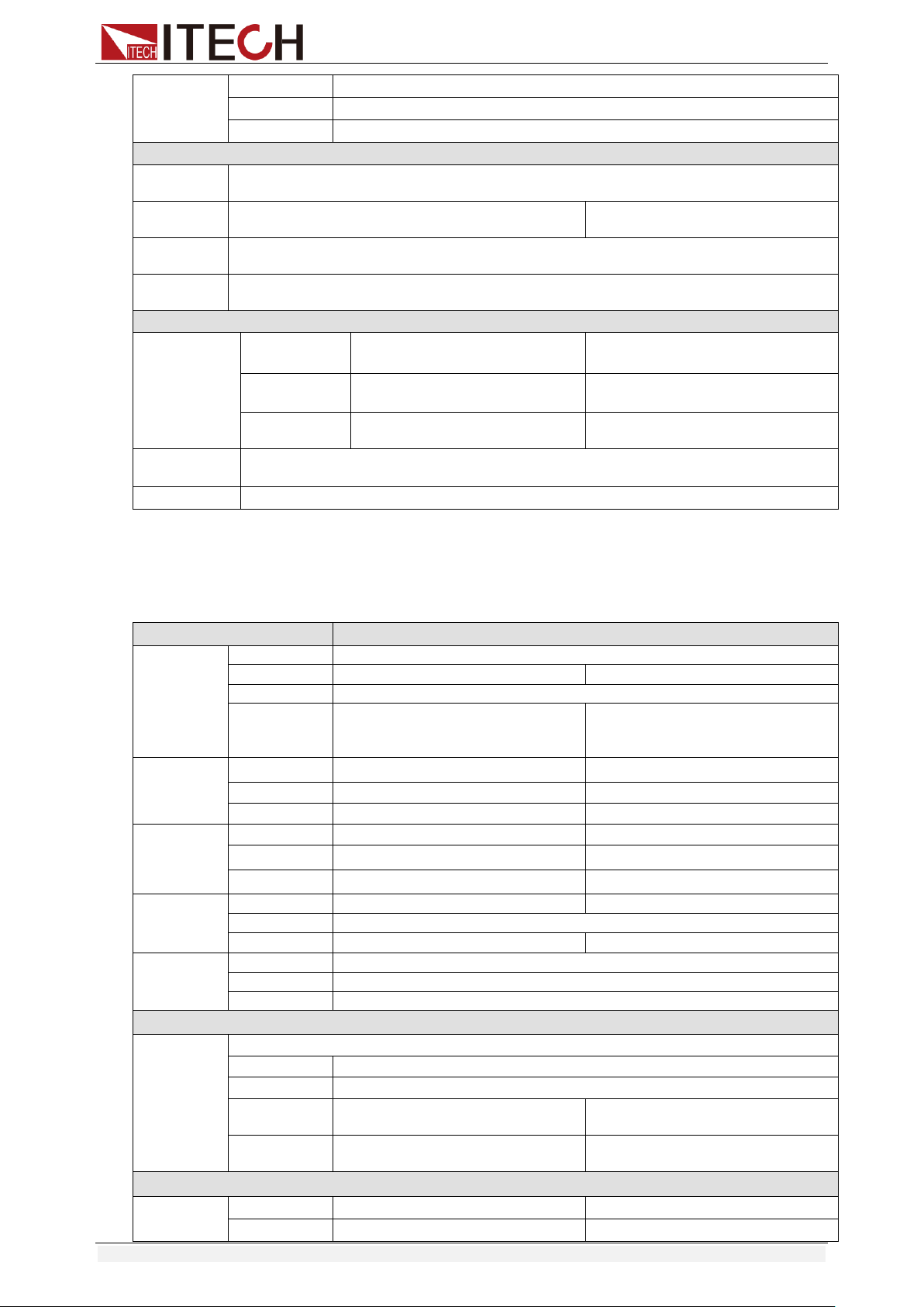
Specifications
Copyright © Itech Electronic Co., Ltd. 55
Readback
power
Range
150W
Resolution
10mW
Accuracy
±(0.1%+0.2%FS)
Protection range
OPP
Protection
≒160W
OCP
Protection
≒3.3A
≒11A
OVP
Protection
≒530V
OTP
Protection
≒85℃
Specification
Short
Current( CC )
≒3.3/3A
≒11/10A
Voltage( CV )
0V
0V
Resistance( C
R )
≒400mΩ
≒400mΩ
Input
Impendance
1MΩ
Dimension
214.5mm*88.2mm*354.6mm
*1 The voltage/current input is no less than 10% FS
*2 The scope of read-back resistance is: (1/(1/R+(1/R)*0.01%+0.08),1/(1/R-(1/R)*0.01%-0.08))
*3 The voltage/current input is no less than 10% FS
*4 Ascending/descending slope: 10%-90% current ascending slope from 0 to maximum current.
*5 Minimum rise time: 10%-90% current rise time
Model
IT8512B+
Rated value
( 0~40 ℃)
Input voltage
0~500V
Input current
0~3A
0~15A
Input power
300W
Minimum
operation
value
0.6V at 3A
3V at 15A
CV mode
Range
0.1~50V
0.1~500V
Resolution
1mV
10mV
Accuracy
±(0.05%+0.05%FS)
±(0.05%+0.05%FS)
CC mode
Range
0~3A
0~15A
Resolution
0.1mA
1mA
Accuracy
±(0.05%+0.05%FS)
±(0.05%+0.05%FS)
CR mode
*1
Range
0.3Ω~10Ω
10Ω~7.5KΩ
Resolution
16bit
Accuracy
0.01%+0.08S *2
0.01%+0.0008S
CP mode
*3
Range
300W
Resolution
10mW
Accuracy
0.1%+0.2%FS
Dynamic mode
Dynamic
mode
CC mode
T1&T2
20uS~3600S /Res:1 uS
Accuracy
2uS±100ppm
Rising/Falling
slope *4
0.0001~0.2A/uS
0.001~0.8A/uS
Minimum rise
time *5
≒10uS
≒10uS
Measuring range
Readback
voltage
Range
0~50V
0~500V
Resolution
1 mV
10 mV
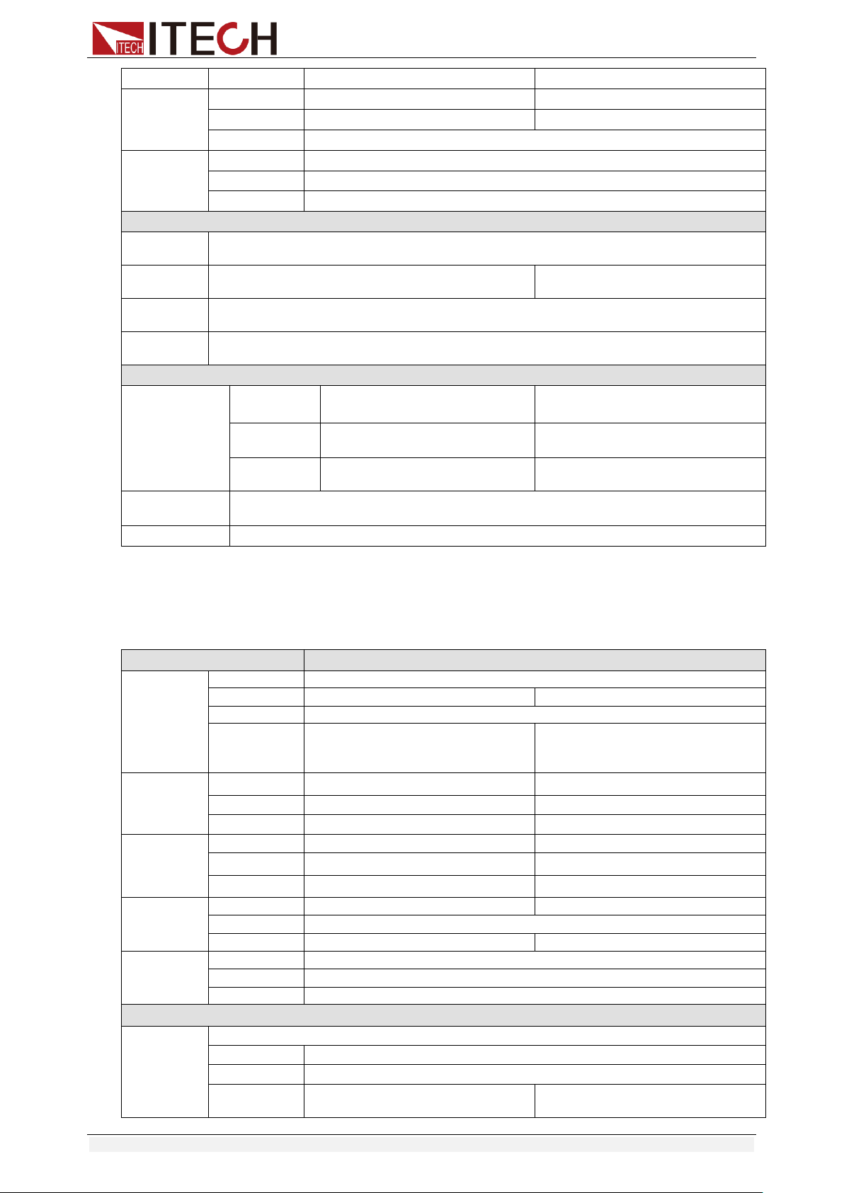
Specifications
Copyright © Itech Electronic Co., Ltd. 56
Accuracy
±(0.025%+0.025%FS)
±(0.025%+0.025%FS)
Readback
current
Range
0~3A
0~15A
Resolution
0.1mA
1mA
Accuracy
±(0.05%+0.05%FS)
Readback
power
Range
300W
Resolution
10mW
Accuracy
±(0.1%+0.2%FS)
Protection range
OPP
Protection
≒320W
OCP
Protection
≒3.3A
≒16A
OVP
Protection
≒530V
OTP
Protection
≒85℃
Specification
Short
Current( CC )
≒3.3/3A
≒16/15A
Voltage( CV )
0V
0V
Resistance(
CR )
≒180mΩ
≒180mΩ
Input
Impendance
1MΩ
Dimension
214.5mm*88.2mm*354.6mm
*1 The voltage/current input is no less than 10% FS
*2 The scope of read-back resistance is: (1/(1/R+(1/R)*0.01%+0.08),1/(1/R-(1/R)*0.01%-0.08))
*3 The voltage/current input is no less than 10% FS
*4 Ascending/descending slope: 10%-90% current ascending slope from 0 to maximum current.
*5 Minimum rise time: 10%-90% current rise time
Model
IT8512C+
Rated value
( 0~40 ℃)
Input voltage
0~120V
Input current
0~6A
0~60A
Input power
300W
Minimum
operation
value
0.25V at 6A
2.5V at 60A
CV mode
Range
0.1~18V
0.1~120V
Resolution
1mV
10mV
Accuracy
±(0.05%+0.02%FS)
±(0.05%+0.025%FS)
CC mode
Range
0~6A
0~60A
Resolution
0.1mA
1mA
Accuracy
±(0.05%+0.05%FS)
±(0.05%+0.1%FS)
CR mode
*1
Range
0.05Ω~10Ω
10Ω~7.5KΩ
Resolution
16bit
Accuracy
0.01%+0.08S *2
0.01%+0.0008S
CP mode
*3
Range
300W
Resolution
10mW
Accuracy
±(0.1%+0.3%FS)
Dynamic mode
Dynamic
mode
CC mode
T1&T2
20uS~3600S /Res:1 uS
Accuracy
2uS±100ppm
Rising/Falling
slope *4
0.0001~0.3A/uS
0.001~3A/uS
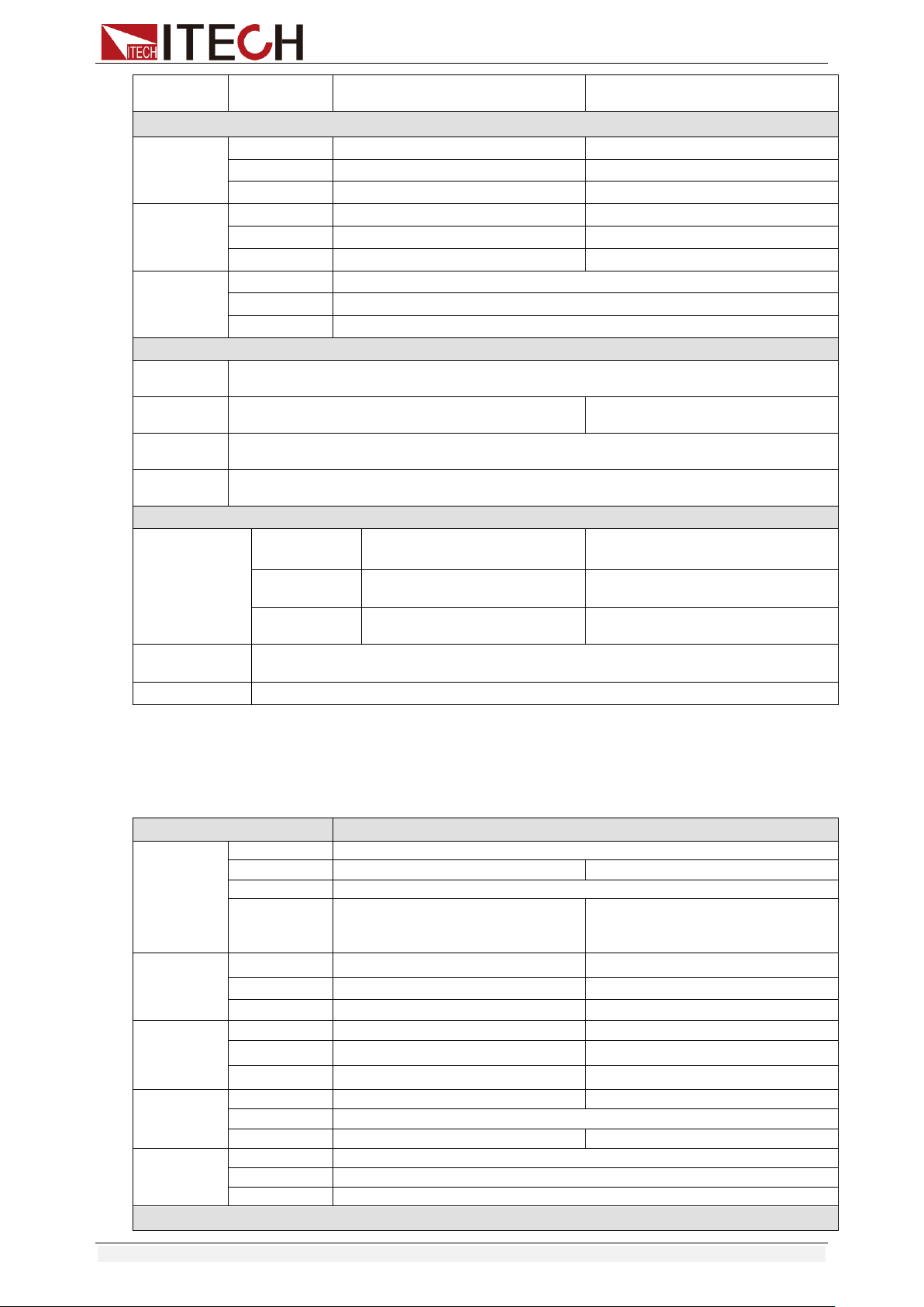
Specifications
Copyright © Itech Electronic Co., Ltd. 57
Minimum rise
time *5
≒10uS
≒10uS
Measuring range
Readback
voltage
Range
0~18V
0~120V
Resolution
0.1 mV
1 mV
Accuracy
±(0.025%+0.025%FS)
±(0.025%+0.025%FS)
Readback
current
Range
0~6A
0~60A
Resolution
0.1mA
1mA
Accuracy
±(0.05%+0.05%FS)
±(0.05%+0.1%FS)
Readback
power
Range
300W
Resolution
10mW
Accuracy
±(0.1%+0.3%FS)
Protection range
OPP
Protection
≒320W
OCP
Protection
≒6.5A
≒65A
OVP
Protection
≒125V
OTP
Protection
≒85℃
Specification
Short
Current( CC )
≒6.5/6A
≒65/60A
Voltage( CV )
0V
0V
Resistance( C
R )
≒40mΩ
≒40mΩ
Input
Impendance
150KΩ
Dimension
214.5mm*88.2mm*354.6mm
*1 The voltage/current input is no less than 10% FS
*2 The scope of read-back resistance is: (1/(1/R+(1/R)*0.01%+0.08),1/(1/R-(1/R)*0.01%-0.08))
*3 The voltage/current input is no less than 10% FS
*4 Ascending/descending slope: 10%-90% current ascending slope from 0 to maximum current.
*5 Minimum rise time: 10%-90% current rise time
Model
IT8512H+
Rated value
( 0~40 ℃)
Input voltage
0~800V
Input current
0~1A
0~5A
Input power
300W
Minimum
operation
value
1.4V at 1A
7V at 5A
CV mode
Range
0.1~80V
0.1~800V
Resolution
1mV
10mV
Accuracy
±(0.05%+0.05%FS)
±(0.05%+0.05%FS)
CC mode
Range
0~1A
0~5A
Resolution
0.1mA
1mA
Accuracy
±(0.05%+0.1%FS)
±(0.05%+0.05%FS)
CR mode
*1
Range
2Ω~10Ω
10Ω~7.5KΩ
Resolution
16bit
Accuracy
0.01%+0.08S *2
0.01%+0.0008S
CP mode
*3
Range
300W
Resolution
10mW
Accuracy
0.2%+0.2%FS
Dynamic mode
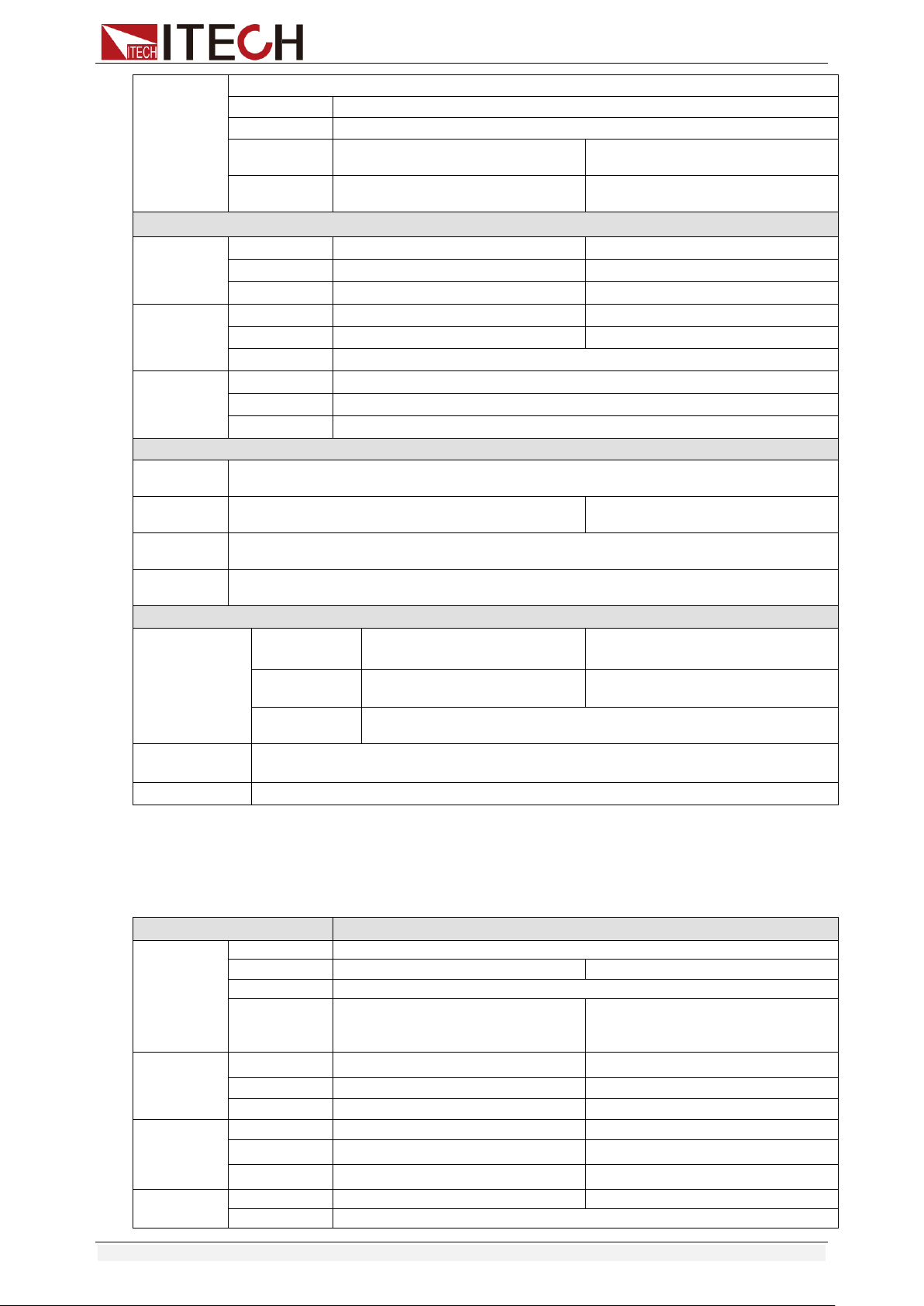
Specifications
Copyright © Itech Electronic Co., Ltd. 58
Dynamic
mode
CC mode
T1&T2
20uS~3600S /Res:1 uS
Accuracy
2uS±100ppm
Rising/Falling
slope *4
0.0001~0.04A/uS
0.001~0.2A/uS
Minimum rise
time *5
≒20uS
≒20uS
Measuring range
Readback
voltage
Range
0~80V
0~800V
Resolution
1 mV
10 mV
Accuracy
±(0.025%+0.025%FS)
±(0.025%+0.025%FS)
Readback
current
Range
0~1A
0~5A
Resolution
0.1mA
1mA
Accuracy
±(0.05%+0.05%FS)
Readback
power
Range
300W
Resolution
10mW
Accuracy
±(0.2%+0.2%FS)
Protection range
OPP
Protection
≒320W
OCP
Protection
≒1.1A
≒5.5A
OVP
Protection
≒850V
OTP
Protection
≒85℃
Specification
Short
Current( CC )
≒1.1/1A
≒5.5/5A
Voltage( CV )
0V
0V
Resistance( C
R )
≒1.4Ω
Input
Impendance
2MΩ
Dimension
214.5mm*88.2mm*354.6mm
*1 The voltage/current input is no less than 10% FS
*2 The scope of read-back resistance is: (1/(1/R+(1/R)*0.01%+0.08),1/(1/R-(1/R)*0.01%-0.08))
*3 The voltage/current input is no less than 10% FS
*4 Ascending/descending slope: 10%-90% current ascending slope from 0 to maximum current.
*5 Minimum rise time: 10%-90% current rise time
Model
IT8513A+
Rated value
( 0~40 ℃)
Input voltage
0~150V
Input current
0~6A
0~60A
Input power
400W
Minimum
operation
value
0.25V at 6A
2.5V at 60A
CV mode
Range
0.1~18V
0.1~150V
Resolution
1mV
10mV
Accuracy
±(0.05%+0.02%FS)
±(0.05%+0.025%FS)
CC mode
Range
0~6A
0~60A
Resolution
0.1mA
1mA
Accuracy
±(0.05%+0.05%FS)
±(0.05%+0.05%FS)
CR mode
*1
Range
0.1Ω~10Ω
10Ω~7.5KΩ
Resolution
16bit
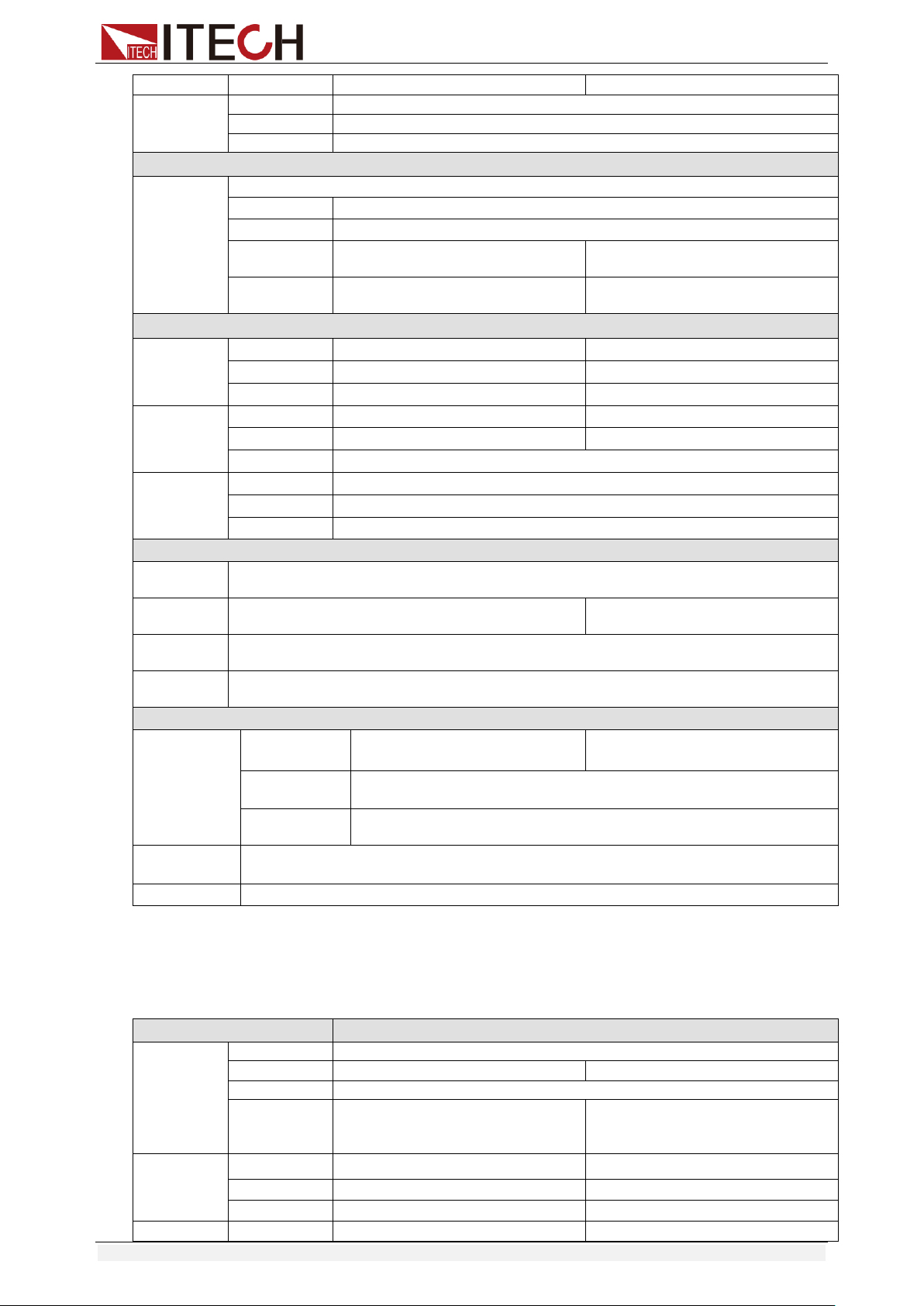
Specifications
Copyright © Itech Electronic Co., Ltd. 59
Accuracy
0.01%+0.08S *2
0.01%+0.0008S
CP mode
*3
Range
400W
Resolution
10mW
Accuracy
±(0.2%+0.2%FS)
Dynamic mode
Dynamic
mode
CC mode
T1&T2
100uS~3600S /Res:1 uS
Accuracy
10Us+100ppm
Rising/Falling
slope *4
0.001~0.15A/uS
0.01~1 A/uS
Minimum rise
time *5
≒50uS
≒60uS
Measuring range
Readback
voltage
Range
0~18V
0~150V
Resolution
0.1 mV
1mV
Accuracy
±(0.025%+0.025%FS)
±(0.025%+0.025%FS)
Readback
current
Range
0~6A
0~60A
Resolution
0.1mA
1mA
Accuracy
±(0.05%+0.05%FS)
Readback
power
Range
400W
Resolution
10mW
Accuracy
±(0.2%+0.2%FS)
Protection range
OPP
Protection
≒420W
OCP
Protection
≒6.6A
≒66A
OVP
Protection
≒165V
OTP
Protection
≒85℃
Specification
Short
Current( CC )
≒6.6/6A
≒66/60A
Voltage( CV )
≒0V
Resistance( C
R )
≒30mΩ
Input
Impendance
≒280KΩ
Dimension
214.5mm*88.2mm*453.5mm
*1 The voltage/current input is no less than 10% FS
*2 The scope of read-back resistance is: (1/(1/R+(1/R)*0.01%+0.08),1/(1/R-(1/R)*0.01%-0.08))
*3 The voltage/current input is no less than 10% FS
*4 Ascending/descending slope: 10%-90% current ascending slope from 0 to maximum current.
*5 Minimum rise time: 10%-90% current rise time
Model
IT8513B+
Rated value
( 0~40 ℃)
Input voltage
0~500V
Input current
0~3A
0~30A
Input power
600W
Minimum
operation
value
0.3V at 3A
3V at 30A
CV mode
Range
0.1~50V
0.1~500V
Resolution
1mV
10mV
Accuracy
±(0.05%+0.05%FS)
±(0.05%+0.05%FS)
CC mode
Range
0~3A
0~30A
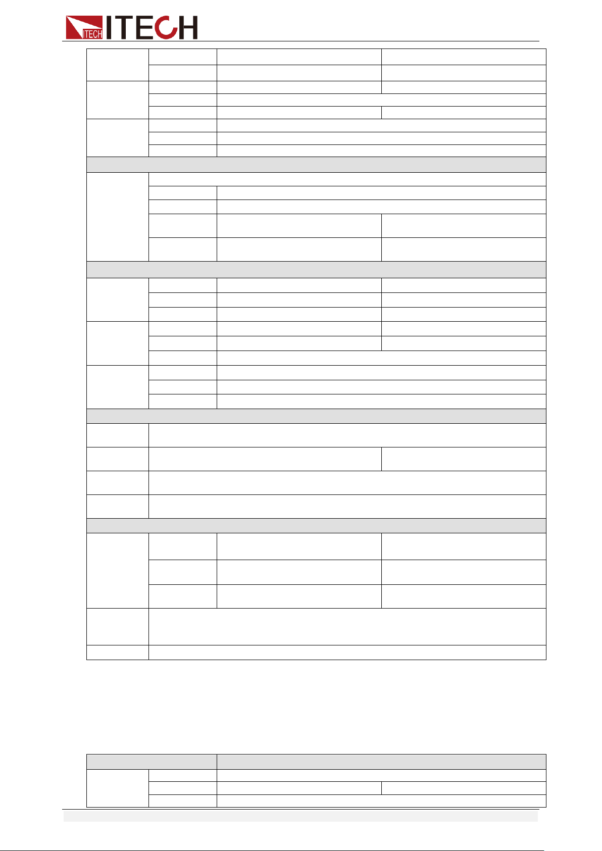
Specifications
Copyright © Itech Electronic Co., Ltd. 60
Resolution
1mA
10mA
Accuracy
±(0.05%+0.05%FS)
±(0.05%+0.05%FS)
CR mode
*1
Range
0.Ω~10Ω
10Ω~7.5KΩ
Resolution
16bit
Accuracy
0.02%+0.08S *2
0.02%+0.0008S
CP mode
*3
Range
600W
Resolution
10mW
Accuracy
±(0.2%+0.2%FS)
Dynamic mode
Dynamic
mode
CC mode
T1&T2
100uS~3600S /Res:1 uS
Accuracy
10uS±100ppm
Rising/Falling
slope *4
0.001~0.05A/uS
0.01~0.5A/uS
Minimum rise
time *5
≒60uS
≒60uS
Measuring range
Readback
voltage
Range
0~50V
0~500V
Resolution
1 mV
10mV
Accuracy
±(0.025%+0.025%FS)
±(0.025%+0.025%FS)
Readback
current
Range
0~3A
0~30A
Resolution
1mA
10mA
Accuracy
±(0.05%+0.05%FS)
Readback
power
Range
600W
Resolution
10mW
Accuracy
±(0.2%+0.2%FS)
Protection range
OPP
Protection
≒650W
OCP
Protection
≒3.3A
≒33A
OVP
Protection
≒530V
OTP
Protection
≒85℃
Specification
Short
Current( CC )
≒3.4/3A
≒34/30A
Voltage( CV )
0V
0V
Resistance( C
R )
≒100mΩ
≒100mΩ
Input
Impendanc
e
1MΩ
Weight
436.5mm*88.2mm*463.5mm
*1 The voltage/current input is no less than 10% FS
*2 The scope of read-back resistance is: (1/(1/R+(1/R)*0.02%+0.08),1/(1/R-(1/R)*0.02%-0.08))
*3 The voltage/current input is no less than 10% FS
*4 Ascending/descending slope: 10%-90% current ascending slope from 0 to maximum
current.
*5 Minimum rise time: 10%-90% current rise time
Model
IT8513C+
Rated value
( 0~40 ℃)
Input voltage
0~120V
Input current
0~12A
0~120A
Input power
600W
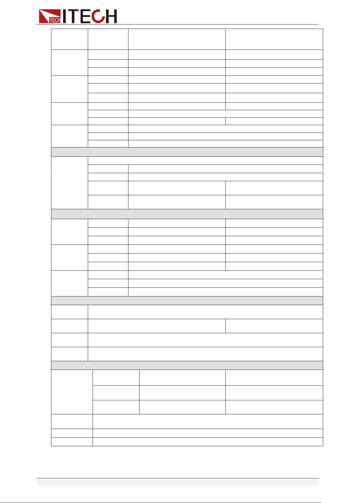
Specifications
Copyright © Itech Electronic Co., Ltd. 61
Minimum
operation
value
0.2V at 12A
2V at 120A
CV mode
Range
0.1~18V
0.1~120V
Resolution
1mV
10mV
Accuracy
±(0.05%+0.02%FS)
±(0.05%+0.025%FS)
CC mode
Range
0~12A
0~120A
Resolution
1mA
10mA
Accuracy
±(0.05%+0.05%FS)
±(0.05%+0.1%FS)
CR mode
*1
Range
0.05Ω~10Ω
10Ω~7.5KΩ
Resolution
16bit
Accuracy
0.01%+0.08S *2
0.01%+0.0008S
CP mode
*3
Range
600W
Resolution
10mW
Accuracy
±(0.2%+0.2%FS)
Dynamic mode
Dynamic
mode
CC mode
T1&T2
100uS~3600S /Res:1 uS
Accuracy
10uS±100ppm
Rising/Falling
slope *4
0.001~0.2A/uS
0.01~1.6A/uS
Minimum rise
time *5
≒60uS
≒60uS
Measuring range
Readback
voltage
Range
0~18V
0~120V
Resolution
0.1 mV
1mV
Accuracy
±(0.025%+0.025%FS)
±(0.025%+0.025%FS)
Readback
current
Range
0~12A
0~120A
Resolution
1mA
10mA
Accuracy
±(0.05%+0.05%FS)
±(0.05%+0.1%FS)
Readback
power
Range
600W
Resolution
10mW
Accuracy
±(0.2%+0.2%FS)
Protection range
OPP
Protection
≒620W
OCP
Protection
≒13A
≒130A
OVP
Protection
≒125V
OTP
Protection
≒95℃
Specification
Short
Current( CC )
≒13/12A
≒130/120A
Voltage( CV )
0V
0V
Resistance( CR
)
≒15mΩ
≒15mΩ
Input
Impendance
150KΩ
Weight
7.1KG
Dimension
214.5mm*88.2mm*453.5mm
*1 The voltage/current input is no less than 10% FS
*2 The scope of read-back resistance is: (1/(1/R+(1/R)*0.01%+0.08),1/(1/R-(1/R)*0.01%-0.08))
*3 The voltage/current input is no less than 10% FS
*4 Ascending/descending slope: 10%-90% current ascending slope from 0 to maximum current.

Specifications
Copyright © Itech Electronic Co., Ltd. 62
*5 Minimum rise time: 10%-90% current rise time
Model
IT8514C+
Rated value
( 0~40 ℃)
Input voltage
0~120V
Input current
0~24A
0~240A
Input power
1500W
Minimum
operation
value
0.25V at 24A
2.5V at 240A
CV mode
Range
0.1~18V
0.1~120V
Resolution
1mV
10mV
Accuracy
±(0.05%+0.02%FS)
±(0.05%+0.025%FS)
CC mode
Range
0~24A
0~240A
Resolution
1mA
10mA
Accuracy
±(0.1%+0.1%FS)
CR mode
*1
Range
0.05Ω~10Ω
10Ω~7.5KΩ
Resolution
16bit
Accuracy
0.02%+0.08S *2
0.02%+0.0008S
CP mode
*3
Range
1500W
Resolution
10mW
Accuracy
±(0.2%+0.2%FS)
Dynamic mode
CC mode
T1&T2
100uS~3600S /Res:1 uS
Accuracy
10uS±100ppm
Rising/Falling slope *4
0.001~0.3A/uS
0.01~3.2A/uS
Minimum rise time *5
≒60uS
≒60uS
Measuring range
Readback
voltage
Range
0~18V
0~120V
Resolution
0.1 mV
1mV
Accuracy
±(0.025%+0.025%FS)
Readback
current
Range
0~24A
0~240A
Resolution
1mA
10mA
Accuracy
±(0.05%+0.05%FS)
Readback
power
Range
1500W
Resolution
10mW
Accuracy
±(0.2%+0.2%FS)
Protection range
OPP
Protection
≒1550W
OCP
Protection
≒26.7A
≒267A
OVP
Protection
≒125V
OTP
Protection
≒85℃
Specification
Short
Current( CC )
≒26.7/24A
≒267/240A
Voltage( CV )
0V
0V
Resistance( CR
)
≒8mΩ
≒8mΩ
Input
Impendance
150KΩ
Dimension
436.5mm*88.2mm*463.5mm
*1 The voltage/current input is no less than 10% FS
*2 The scope of read-back resistance is: (1/(1/R+(1/R)*0.02%+0.08),1/(1/R-(1/R)*0.02%-0.08))
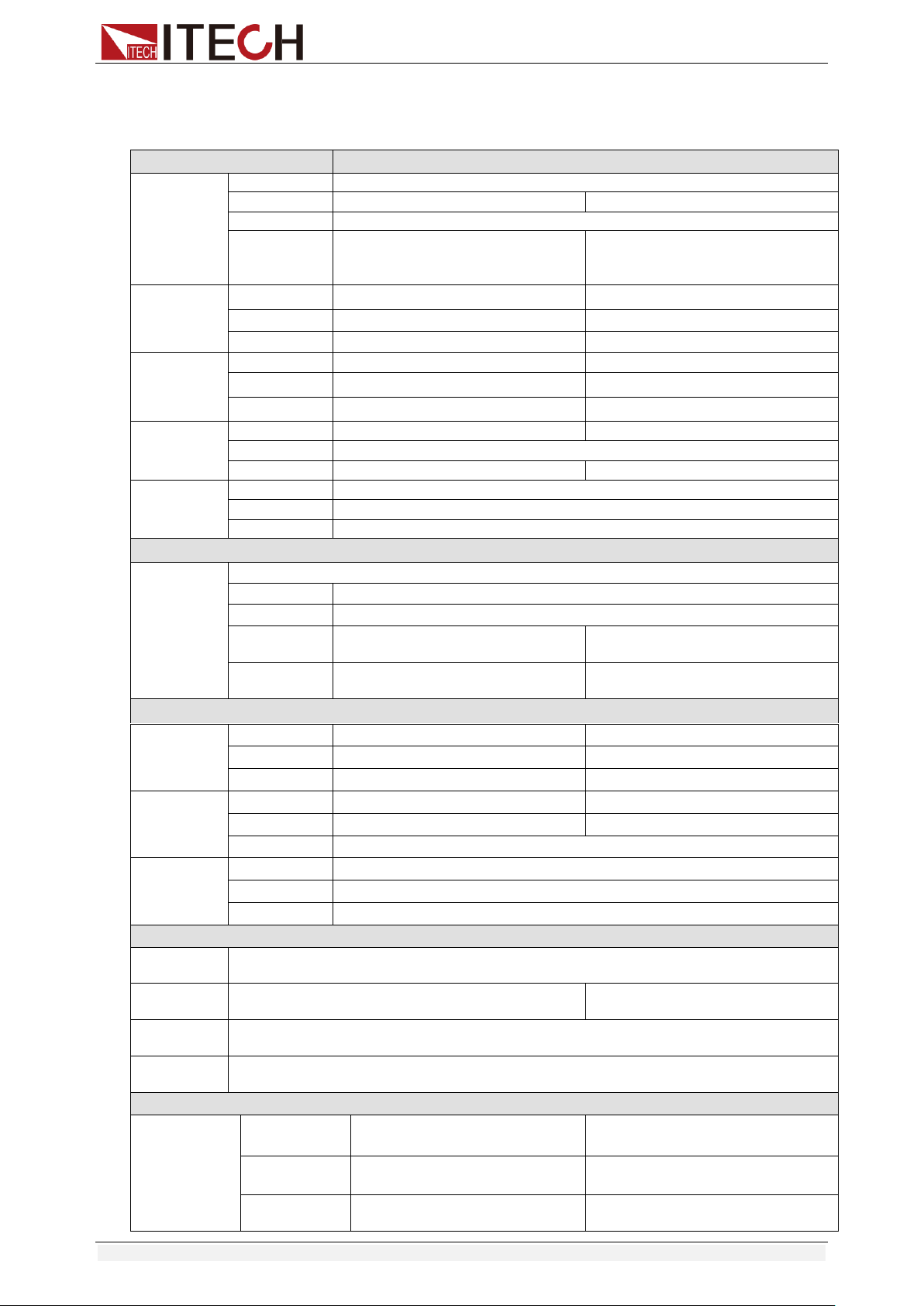
Specifications
Copyright © Itech Electronic Co., Ltd. 63
*3 The voltage/current input is no less than 10% FS
*4 Ascending/descending slope: 10%-90% current ascending slope from 0 to maximum current.
*5 Minimum rise time: 10%-90% current rise time
Model
IT8514B+
Rated value
( 0~40 ℃)
Input voltage
0~500V
Input current
0~6A
0~60A
Input power
1500W
Minimum
operation
value
0.3V at 6A
3V at 60A
CV mode
Range
0.1~50V
0.1~500V
Resolution
1mV
10mV
Accuracy
±(0.05%+0.05%FS)
±(0.05%+0.05%FS)
CC mode
Range
0~6A
0~60A
Resolution
1mA
10mA
Accuracy
±(0.05%+0.05%FS)
±(0.05%+0.05%FS)
CR mode
*1
Range
0.05Ω~10Ω
10Ω~7.5KΩ
Resolution
16bit
Accuracy
0.02%+0.08S *2
0.02%+0.0008S
CP mode
*3
Range
1500W
Resolution
10mW
Accuracy
±(0.2%+0.2%FS)
Dynamic mode
Dynamic
mode
CC mode
T1&T2
100uS~3600S /Res:1 uS
Accuracy
10uS±100ppm
Rising/Falling
slope *4
0.001~0.15A/uS
0.01~0.8A/uS
Minimum rise
time *5
≒60uS
≒60uS
Measuring range
Readback
voltage
Range
0~50V
0~500V
Resolution
0.1 mV
1mV
Accuracy
±(0.025%+0.025%FS)
±(0.025%+0.025%FS)
Readback
current
Range
0~6A
0~60A
Resolution
1mA
10mA
Accuracy
±(0.05%+0.05%FS)
Readback
power
Range
1500W
Resolution
10mW
Accuracy
±(0.2%+0.2%FS)
Protection range
OPP
Protection
≒1550W
OCP
Protection
≒6.7A
≒67A
OVP
Protection
≒530V
OTP
Protection
≒85℃
Specification
Short
Current( CC )
≒6.7/6A
≒67/60A
Voltage( CV )
0V
0V
Resistance( C
R )
≒50mΩ
≒50mΩ
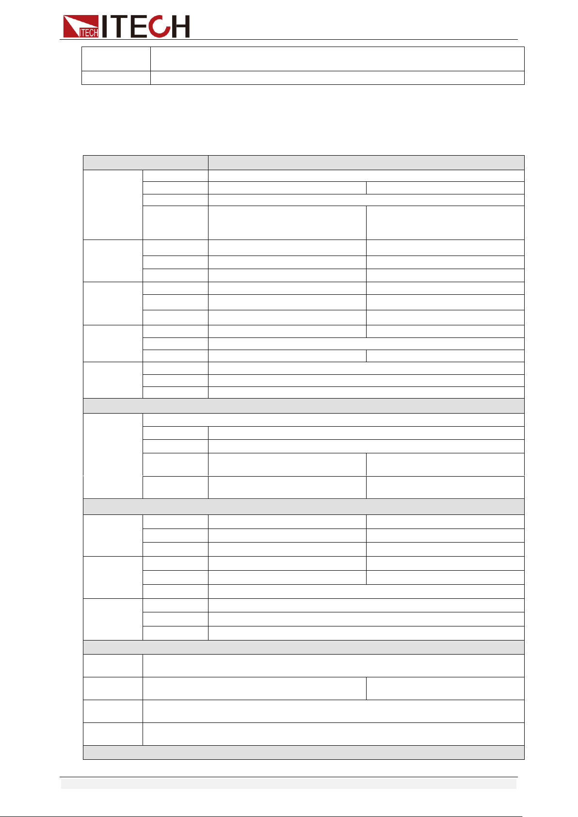
Specifications
Copyright © Itech Electronic Co., Ltd. 64
Input
Impendance
1MΩ
Dimension
436.5mm*88.2mm*463.5mm
*1 The voltage/current input is no less than 10% FS
*2 The scope of read-back resistance is: (1/(1/R+(1/R)*0.02%+0.08),1/(1/R-(1/R)*0.02%-0.08))
*3 The voltage/current input is no less than 10% FS
*4 Ascending/descending slope: 10%-90% current ascending slope from 0 to maximum current.
*5 Minimum rise time: 10%-90% current rise time
Model
IT8516C+
Rated value
( 0~40 ℃)
Input voltage
0~120V
Input current
0~24A
0~240A
Input power
3000W
Minimum
operation
value
0.15V at 24A
1.5V at 240A
CV mode
Range
0.1~18V
0.1~120V
Resolution
1mV
10mV
Accuracy
±(0.05%+0.025%FS)
±(0.05%+0.025%FS)
CC mode
Range
0~24A
0~240A
Resolution
1mA
10mA
Accuracy
±(0.1%+0.1%FS)
±(0.1%+0.1%FS)
CR mode
*1
Range
0.05Ω~10Ω
10Ω~7.5KΩ
Resolution
16bit
Accuracy
0.02%+0.08S *2
0.02%+0.0008S
CP mode
*3
Range
3000W
Resolution
10mW
Accuracy
±(0.2%+0.2%FS)
Dynamic mode
Dynamic
mode
CC mode
T1&T2
120uS~3600S /Res:1 uS
Accuracy
10uS+100ppm
Rising/Falling
slope *4
0.001~0.25A/uS
0.01~2.5A/uS
Minimum rise
time *5
≒70uS
≒70uS
Measuring range
Readback
voltage
Range
0~18V
0~120V
Resolution
0.1 mV
1mV
Accuracy
±(0.025%+0.025%FS)
±(0.025%+0.025%FS)
Readback
current
Range
0~24A
0~240A
Resolution
1mA
10mA
Accuracy
±(0.1%+0.1%FS)
Readback
power
Range
3000W
Resolution
10mW
Accuracy
±(0.2%+0.2%FS)
Protection range
OPP
Protection
≒3000W
OCP
Protection
≒26A
≒260A
OVP
Protection
≒125V
OTP
Protection
≒85℃
Specification

Specifications
Copyright © Itech Electronic Co., Ltd. 65
Short
Current( CC )
≒26/24A
≒260/240A
Voltage( CV )
0V
0V
Resistance(
CR )
≒6mΩ
≒6mΩ
Input
Impendance
≒300KΩ
Dimension
436.5mm*176mm*463.5mm
*1 The voltage/current input is no less than 10% FS
*2 The scope of read-back resistance is: (1/(1/R+(1/R)*0.02%+0.08),1/(1/R-(1/R)*0.02%-0.08))
*3 The voltage/current input is no less than 10% FS
*4 Ascending/descending slope: 10%-90% current ascending slope from 0 to maximum current.
*5 Minimum rise time: 10%-90% current rise time
* The above specifications may be subject to change without prior notice.
Supplementary Characteristics
Memory capacity: 100 registers
Suggested calibration frequency: Once a year
AC input level (A transfer switch is selectable on the rear panel)
Option Opt.1: 220V ±10% 50Hz/60Hz
Option Opt.2: 110V ±10% 50Hz/60Hz
Cooling type
Intelligent fans
Fans working principle:
Fans running speed is determined by radiator temperature.When
temperature reaches 40℃,fans start to work and intelligently adjust its
speed with temperature variation.
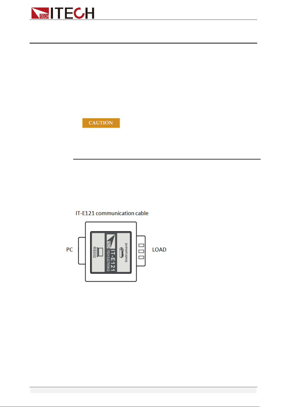
Communication Interfaces
Copyright © Itech Electronic Co., Ltd. 66
Chapter6 Communication Interfaces
6.1 Communication Modules Introduction
DB9 in the rear panel of the DC load IT8511+/IT8511A+/IT8511B+/IT8512+
/IT8512A+/IT8512B+/IT8512C+/IT8512H+/IT8513A+/IT8513C+ is TTL level,
which can be connected to the serial port of the PC through the level
conversion of the accessory.
The communication module is IT-E121/IT-E121A/IT-E122/IT-E123.
The IT8513B+/IT8514B+/IT8514C+/IT8516C+ comes standard with RS232
and USB communication interfaces.
Please do not connect the standard RS232 cable to the
IT8511+/IT8511A+/IT8511B+/IT8512+/IT8512A+/IT8512B+/IT8512C
+/IT8512H+/IT8513A+/IT8513C+ electronic load, which may
damage the instrument.
IT-E121 Communication Module
The DB9 interface connector on the rear panel of the DC load is TTL voltage
level; you can use the communication module IT-E121 and a standard RS232
extension cable to connect the DB9 interface connector of the DC load and the
RS-232 interface connector of computer for the communication.
IT-E121A Communication Module
The DB9 interface connector on the rear panel of the DC load is TTL voltage
level; you can use the communication module IT-E121A and a standard RS232
extension cable to connect the DB9 interface connector of the DC load and the
RS-232 interface connector of computer for the communication.
IT-E121A is derived on the basis of IT-E121, the main difference between them
is that the DB9 interface connector of the RS232 changes from female to male,
so that can be directly connected to the standard LAN interface.
IT-E121A communication cable
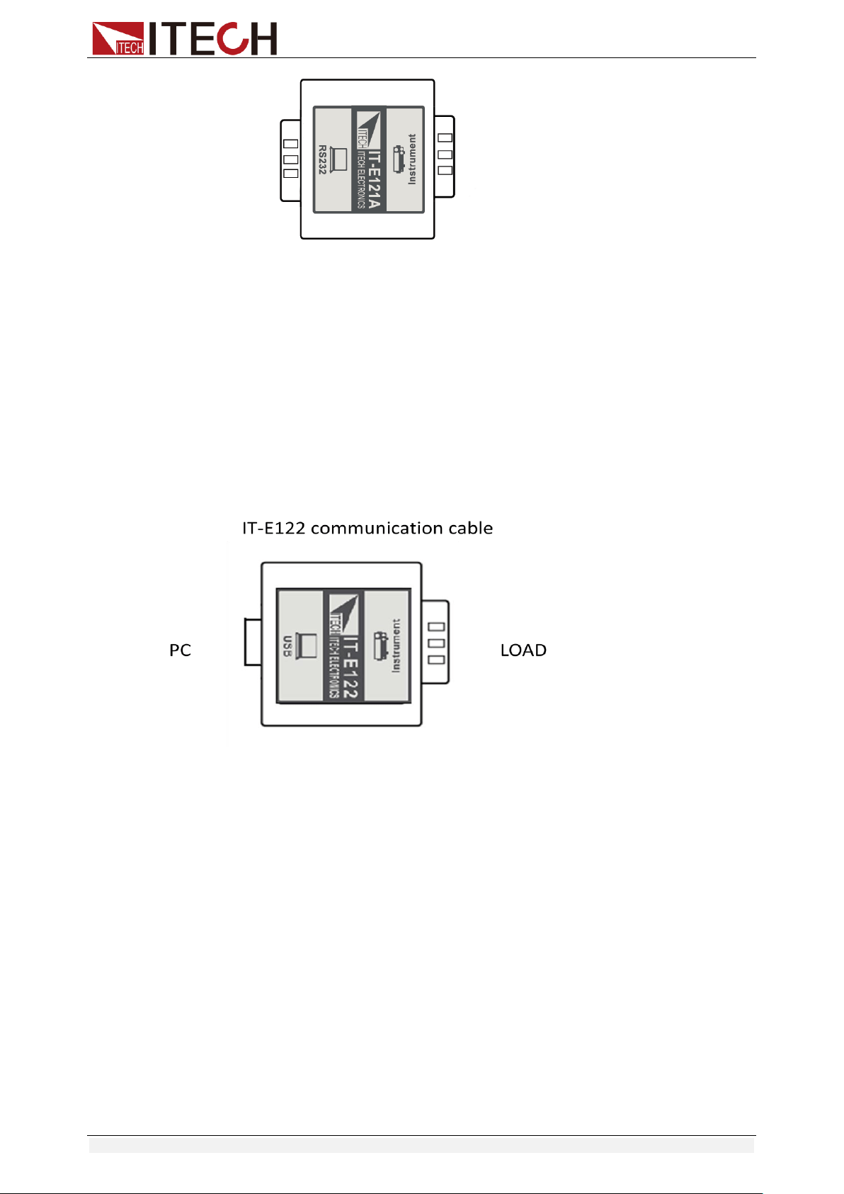
Communication Interfaces
Copyright © Itech Electronic Co., Ltd. 67
IT-E122 Communication Module
The DB9 interface connector on the rear panel of the DC load is TTL voltage
level; IT-E122 has a USB interface (male connector B) on one end, you can use
IT-E122 and a standard USB extension cable (type B female connector at one
end and type A at one end) to connect the DB9 interface connector of the DC
load and the USB interface connector of computer for the communication.
After connecting the load and computer by USB, you need to install IT-E122
driver (download from
http://www.itech.sh/support/Down-3.htm?model=IT-E122%20%E5%85%89%E
9%9A%94%E7%A6%BB%E9%80%9A%E8%AE%AF%E6%8E%A5%E5%8F
%A3%E9%A9%B1%E5%8A%A8 or contact ITECH agent). The device
manager of PC will display ‘Prolific USB-to-Serial COM Port’ after installing.
IT-E123 Communication Module
The DB9 interface connector on the rear panel of the DC load is TTL voltage
level;
The interface on both side port of IT-E123 are DB9 interface and RS485
interface, you can use the communication module IT-E123 and an a standard
RS485-RS232 conversion cable to connect the DB9 interface connector of the
DC load and the RS-232 interface connector of computer for the
communication.
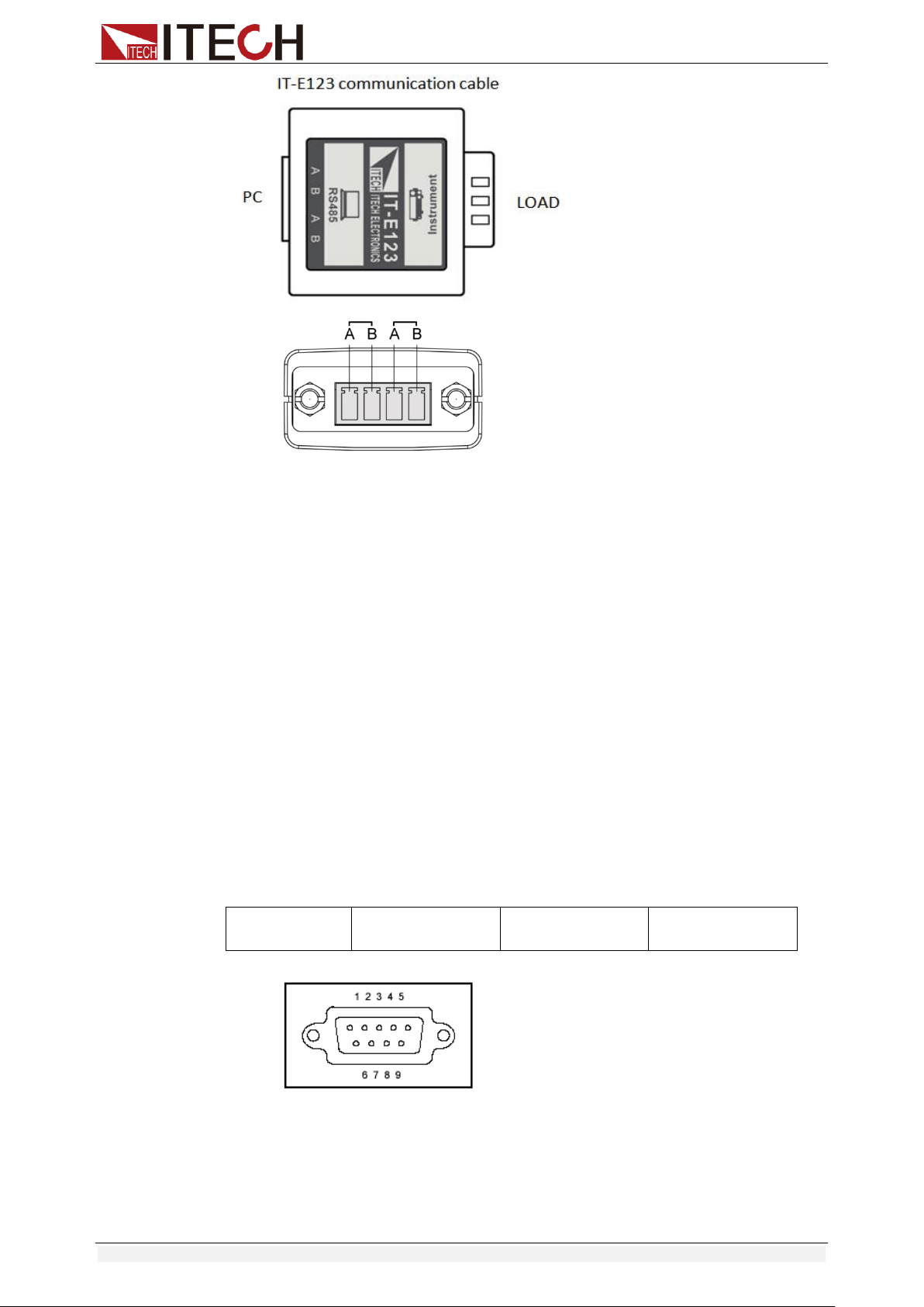
Communication Interfaces
Copyright © Itech Electronic Co., Ltd. 68
RS485 pins
6.2 Communication with PC
Before using the remote operation mode, please make sure that the baud rate
and communication address in the DC load are the same as in the computer
software, otherwise, the communication will fail, you can change the baud rate
and communication address from the front panel or from computer.
DB9 Serial Port
In order for the computer to communicate with the DC load, both must be set to
the same RS-232 settings. These communication settings are:
1. Baud rate: 4800,9600,19200 and 38400 are selectable, default setting is
9600.
2. Data bit: 8 bit
3. Stop bit: 1
4. Parity: None
5. Address: the range is from 0 to 31, default setting is 0
Start Bit
8 Data Bits
Parity=None
Stop Bit
RS-232
IT8513B+/IT8514B+/IT8514C+/IT8516C+ electronic load has a DB9 interface
on rear panel. Connect E-load and computer by cable of COM ends (DB9).
Composite key [Shift] + [8] on front board can be used to enter system menu
for activation.
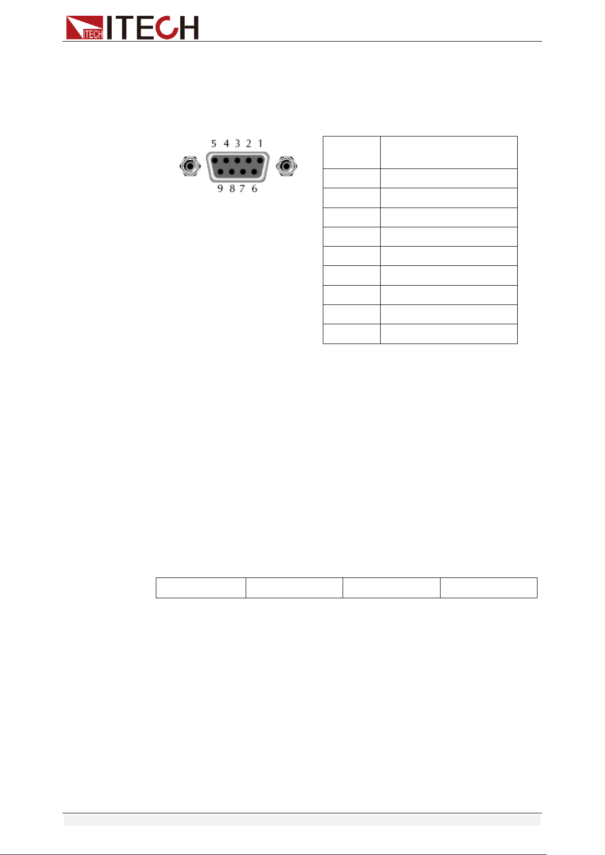
Communication Interfaces
Copyright © Itech Electronic Co., Ltd. 69
RS-232 Interface
In RS-232 interface, all SCPI commands can be used for programming. If
RS-232 interface is selected, in accordance with internal connection of data
terminal equipment (DTE) and data communication equipment (DCE) as
defined in EIA RS-232, the load is connected to another DTE (e.g., PC COM
interface) with direct-connected Modem cable.
RS232 Pins of Plug
Base Pin
Number
Description
1
No conjunction
2
TXD, data transmission
3
RXD, data receiving
4
No conjunction
5
GND, grounding
6
No conjunction
7
CTS, clear to send
8
RTS, request to send
9
No conjunction
Communication Setup
Please ensure the PC and the load have the same configuration in the following
items.
Baudrate: 9600(4800, 9600, 19200, 38400). You could enter the system menu
to set the baudrate.
Data bit: 8
Stop bit: 1
Parity bit: (none, even, odd)
EVEN 8 data bits have even parity
ODD 8 data bits have odd parity
NONE 8 data bits have no parity
Native machine address: (0 ~31, factory default is 0)
Start Bit
8 Data Bits
Parity=None
Stop Bit
USB Interface
Connect the load and the computer using a cable with two USB interfaces
(each end). All functions of the load can be programmed via USB.
After connecting the load and computer by USB, you need to install IT-E122
driver (download from
http://www.itech.sh/support/Down-3.htm?model=IT-E122%20%E5%85%89%E
9%9A%94%E7%A6%BB%E9%80%9A%E8%AE%AF%E6%8E%A5%E5%8F
%A3%E9%A9%B1%E5%8A%A8 or contact ITECH agent). The device
manager of PC will display ‘Prolific USB-to-Serial COM Port’ after installing.
Notes: Only IT8513B+/IT8514B+/IT8514C+/IT8516C+ models have the USB
communication interface. After the driver is installed successfully, use USB line
to connect in communication. (Please don’t connect DB9 interface at the same
time). Don’t need to set the menu.
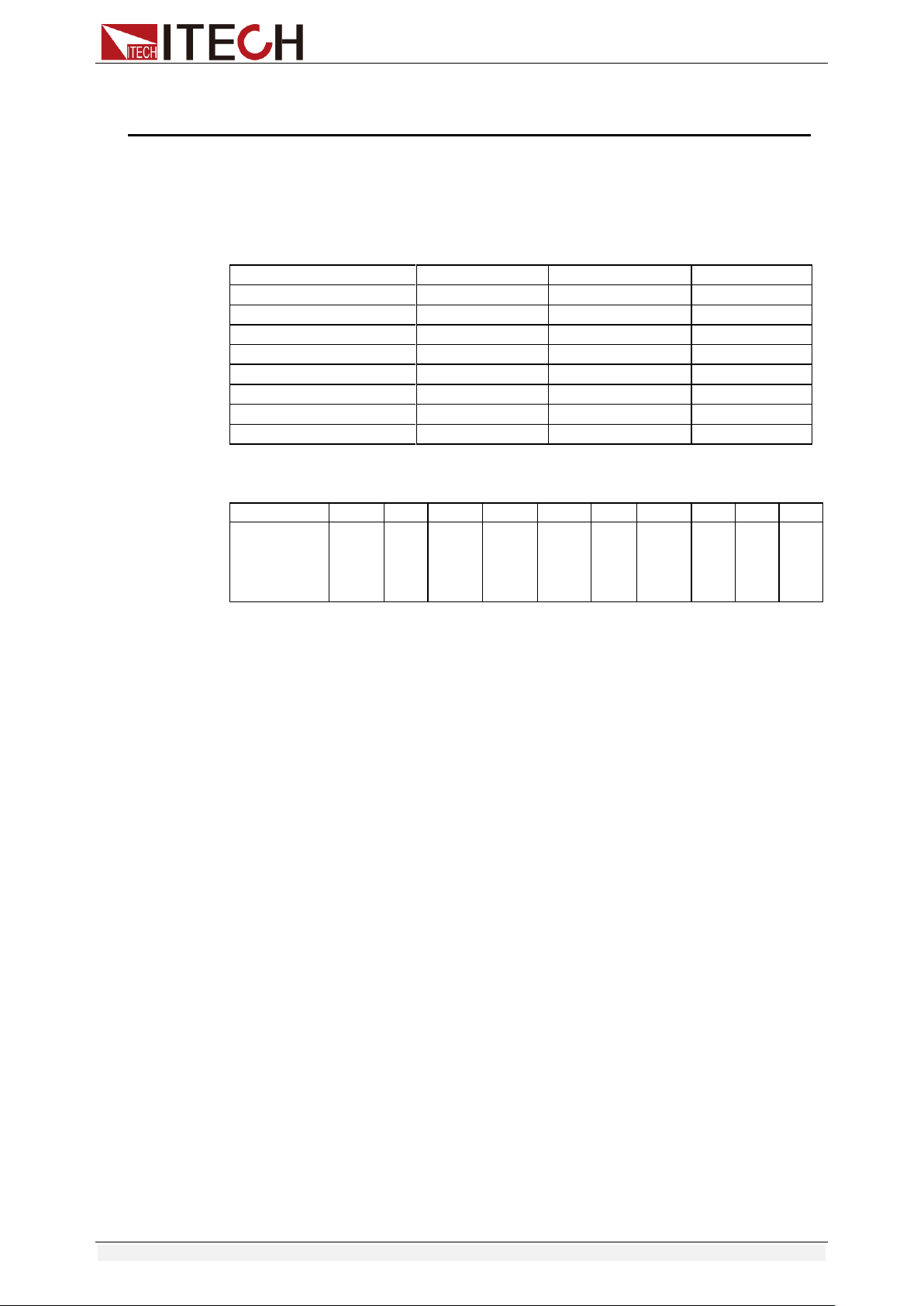
Appendix
Copyright © Itech Electronic Co., Ltd. 70
Appendix
Specifications of Red and Black Test Lines
ITECH provides you with optional red and black test lines, which individual
sales and you can select for test. For specifications of ITECH test lines and
maximum current values, refer to the table below.
Model
Specification
Cross Section
Length
IT-E301/10A
10A
-
1m
IT-E301/30A
30A
6mm
2
1.2m
IT-E301/30A
30A
6mm
2
2m
IT-E301/60A
60A
20mm
2
1.5m
IT-E301/120A
120A
50mm
2
2m
IT-E301/240A
240A
70mm
2
1m
IT-E301/240A
240A
70mm
2
2m
IT-E301/360A
360A
95mm
2
2m
For maximum current of AWG copper wire, refer to table blow.
AWG
10
12
14
16
18
20
22
24
26
28
The
Maximum
Current
Value( A)
40
25
20
13
10
7
5
3.5
2.5
1.7
Note: AWG ( American Wire Gage), it means X wire ( marked on the wire). The
table above lists current capacity of single wire at working temperature of 30°C.
For reference only.