
ALEXA 35
Software Update Package 1.1
U S E R M A N U A L
May 2, 2023

Disclaimer 2
Disclaimer
Before using the products, be sure to read and understood all respective instructions.
The products are available for commercial customers only.
For product specification changes since this manual was published, refer to the latest publications of
ARRI data sheets or data books, etc., for the most up-to-date specifications. Not all products and/or
types are available in every country. Please check with an ARRI sales representative for availability and
additional information.
ARRI assumes no responsibility for any errors that may appear in this document. The information is
subject to change without notice.
While ARRI endeavors to enhance the quality, reliability and safety of their products, customers agree
and acknowledge that the possibility of defects thereof cannot be eliminated entirely. To minimize
risk of damage to property or injury (including death) to persons arising from defects in the products,
customers must incorporate sufficient safety measures in their work with the system and have to heed
the stated canonic use.
ARRI or its subsidiaries expressly exclude any liability, warranty, demand or other obligation for any
claim, representation, or cause, or action, or whatsoever, express or implied, whether in contract or tort,
including negligence, or incorporated in terms and conditions, whether by statue, law or otherwise. In
no event shall ARRI or its subsidiaries be liable for or have a remedy for recovery of any special, direct,
indirect, incidental, or consequential damages, including, but not limited to lost profits, lost savings, lost
revenues or economic loss of any kind or for any claim by third party, downtime, good will, damage to or
replacement of equipment or property, any cost or recovering of any material or goods associated with
the assembly or use of our products, or any other damages or injury of the persons and so on or under
any other legal theory.
Neither ARRI nor its subsidiaries assume any liability for infringement of patents, copyrights or other
intellectual property rights of third parties by or arising from the use of ARRI products or any other
liability arising from the use of such products. No license, express, implied or otherwise, is granted
under any patents, copyrights or other intellectual property right of ARRI or others.
ARRI or its subsidiaries do not assume any responsibility for incurred losses due to improper handling
or configuration of the camera or other system components, due to sensor contamination, occurrence
of dead or defective pixels, defective signal connections or incompatibilities with third party recording
devices.
In the case one or all of the foregoing clauses are not allowed by applicable law, the fullest extent
permissible clauses by applicable law are validated.

Imprint 3
Imprint
© 2023 Arnold & Richter Cine Technik GmbH & Co. Betriebs KG. All rights reserved.
The system contains proprietary information of Arnold & Richter Cine Technik GmbH & Co. Betriebs
KG. It is provided under a license agreement containing restrictions on use and disclosure and
protected by copyright law. Reverse engineering of the software is prohibited.
No part of this publication may be reproduced, stored in a retrieval system, or transmitted in any form
or by any means, electronic, mechanical, photocopying, recording or otherwise without the prior written
permission of Arnold & Richter Cine Technik GmbH & Co. Betriebs KG.
Due to continued product development the information in this document may change without notice.
The information and intellectual property contained herein is confidential between ARRI and the client
and remains the exclusive property of ARRI. If you find any problems in the documentation, please
report them to us in writing. ARRI does not warrant that this document is flawless.
ARRI, ALEXA 35 and ARRIRAW are trademarks or registered trademarks of Arnold & Richter Cine
Technik GmbH & Co. Betriebs KG. All other brands or products mentioned are trademarks or registered
trademarks of their respective holders and should be treated as such.
Apple ProRes 422 HQ, Apple ProRes 4444, Apple ProRes 4444 XQ, and the
ProRes logo are trademarks or registered trademarks of Apple Computer, Inc., used
under license therefrom.
Original version.
For Further Assistance
Arnold & Richter Cine Technik GmbH & Co. Betriebs KG
Herbert-Bayer-Str. 10
80807 Munich
Germany
www.arri.com/en/technical-service

Contents 4
1 Contents
1 Contents.............................................................................................................................4
2 About this Document....................................................................................................... 7
3 Introduction to the ALEXA 35......................................................................................... 8
4 Camera Body Overview................................................................................................... 9
5 Multi Viewfinder MVF-2 Overview................................................................................. 15
6 Power Supply.................................................................................................................. 19
7 Menu Operation...............................................................................................................22
7.1 HOME Screen.................................................................................................................22
7.2 On-screen Keyboard.......................................................................................................25
7.3 Working with Lists and Importing Files.......................................................................... 25
7.4 Side Display.................................................................................................................... 28
7.5 User Storage...................................................................................................................29
7.6 Info Screens....................................................................................................................30
8 Status Information and Overlays.................................................................................. 32
9 Main Parameters............................................................................................................. 36
9.1 Project Settings...............................................................................................................36
9.2 Sensor Frame Rate........................................................................................................ 37
9.3 Shutter.............................................................................................................................37
9.4 Exposure Index...............................................................................................................39
9.5 ND Filter..........................................................................................................................40
9.6 White Balance.................................................................................................................40
9.7 Timecode.........................................................................................................................41
10 Look Settings.................................................................................................................. 43
10.1 Color Processing and Color Space................................................................................43
10.2 Look File ALF4............................................................................................................... 45
10.3 Setting the Look..............................................................................................................45
10.4 Look Intensity..................................................................................................................46
11 ARRI Textures................................................................................................................. 47
12 Recording.........................................................................................................................49
12.1 Recording Medium..........................................................................................................49
12.2 Recording Codec............................................................................................................ 51
12.3 Sensor Mode & Recording Resolution........................................................................... 52
12.4 Starting Recording.......................................................................................................... 55
12.5 Prerecording....................................................................................................................55
12.6 Clip Naming Scheme......................................................................................................58

Contents 5
12.7 Audio Recording............................................................................................................. 59
12.8 Rec Beeper and Tally..................................................................................................... 61
13 Playback...........................................................................................................................62
14 Monitoring........................................................................................................................64
14.1 Surround View................................................................................................................ 64
14.2 Magnification................................................................................................................... 65
14.3 Frame Lines.................................................................................................................... 66
14.4 False Color..................................................................................................................... 68
14.5 Peaking........................................................................................................................... 69
14.6 Zoom............................................................................................................................... 70
14.7 SDI Settings.................................................................................................................... 71
14.8 EVF and Flip-out Monitor Settings................................................................................. 72
14.9 Return In......................................................................................................................... 74
14.10 SDI Color Bars................................................................................................................74
15 User Buttons................................................................................................................... 75
16 Synchronization.............................................................................................................. 78
17 Sensor Settings...............................................................................................................79
17.1 Mirroring the Sensor Image............................................................................................79
17.2 User Pixel Masking.........................................................................................................79
18 System Settings.............................................................................................................. 81
18.1 Language Setting............................................................................................................81
18.2 System Time and Date...................................................................................................81
18.3 Button and Display Settings........................................................................................... 81
18.4 Fan Settings....................................................................................................................81
18.5 Reset of Electronic Horizon............................................................................................81
18.6 Update.............................................................................................................................82
18.6.1 Update of Camera Software.........................................................................................82
18.6.2 Update of Camera Components.................................................................................. 82
18.6.3 Update of LBUS Devices............................................................................................. 83
18.6.4 Update of Codex Compact Drive................................................................................. 83
18.6.5 Update of PDM-1..........................................................................................................83
19 User Setups..................................................................................................................... 84
19.1 User Setup Parameter Blocks........................................................................................ 85
20 Network............................................................................................................................ 86
20.1 WiFi Settings...................................................................................................................86
20.2 Ethernet Settings............................................................................................................ 88
20.3 Streaming Metadata....................................................................................................... 88

Contents 6
21 Metadata...........................................................................................................................90
22 Lens & Electronic Control System (ECS).................................................................... 91
22.1 Lens Data....................................................................................................................... 91
22.2 Lens Data Archive.......................................................................................................... 92
22.3 White Radio Configuration..............................................................................................93
22.4 Lens Motors.................................................................................................................... 95
22.5 Changing a Lens............................................................................................................ 96
22.6 EF Lens Iris Adjustment................................................................................................. 97
22.7 Enable Lens Mount.........................................................................................................98
23 Remote Control............................................................................................................... 99
23.1 Web Remote................................................................................................................... 99
23.2 Camera Access Protocol (CAP)................................................................................... 100
23.3 Camera Companion App.............................................................................................. 100
23.4 Hand Units Hi-5 and WCU-4........................................................................................101
24 ALEXA 35 Accessories................................................................................................ 102
24.1 Lens Mounts................................................................................................................. 102
24.1.1 Changing the Lens Mount.......................................................................................... 103
24.2 Mechanical Accessories............................................................................................... 106
24.2.1 Bottom Accessories.................................................................................................... 106
24.2.2 Top Accessories..........................................................................................................108
24.2.3 Side Accessories........................................................................................................ 110
24.2.4 Other Accessories...................................................................................................... 111
24.3 Electronic Accessories..................................................................................................112
24.4 Battery Adapters........................................................................................................... 113
25 Appendix........................................................................................................................ 115
25.1 Data Rates, Recording Times and Max. FPS.............................................................. 115
25.2 Sensor Related Information..........................................................................................117
25.3 Companion Tools.......................................................................................................... 117
25.4 Connector Pin-Outs...................................................................................................... 119
25.5 Dimensional Drawings.................................................................................................. 121

About this Document 7
2 About this Document
This user manual is aimed at everyone involved in using the system and provides directions on how to
operate it safely and as intended.
To ensure safe and correct use, all users need to read the ALEXA 35 Operating Manual before using
the system for the first time. It contains detailed information on how to use the system safely.
This user manual is an essential part of the product and should be easily accessible and in proximity to
the equipment so that users can use it as a reference anytime.
Keep the ALEXA 35 User Manual, the ALEXA 35 Operating Manual and all other instructions belonging
to the system in a safe place for future reference and possible subsequent owners.
Document Revision History
Document ID: D45 10006703
Version Release Date Description
1.0
1.1
K10948
K11240
July 18, 2022
May 2, 2023
Initial Release
Release for SUP 1.1
How To Use This Manual
All directions are given from a camera operator's point of view. For example, camera right side refers to
the right side of the camera when standing behind the camera and operating it in a normal fashion.
Connectors are written in all capital letters, for example “AUDIO connector”.
Buttons are written in italic typeface capital letters, for example “PLAY button”.
Menu paths are written in italic typeface, with menu and home in capital letters, for example “MENU >
Recording > Sensor Mode”.
“EVF” refers to the OLED eyepiece of the MVF-2 viewfinder.
“Monitor” refers to the flip-out monitor of the MVF-2 viewfinder.
“VF” refers to the viewfinder connectors VF 1 and VF 2. When settings refer to VF, they affect the EVF
and the flip-out monitor.
“Monitoring outputs” refers to EVF, flip-out monitor, SDI 1 and SDI 2.
“Status Info” refers collectively to the Status Info of EVF, SDI 1 and SDI 2.
Strengthen Your Knowledge and Get Trained
The ARRI Academy courses provide unrivaled insights into the full possibilities of working with ARRI
camera systems, lenses, lights and accessories.
To learn more, please visit http://arri.com/academy.

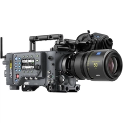
Introduction to the ALEXA 35 8
3 Introduction to the ALEXA 35
ALEXA 35 is a 4K Super 35 camera that elevates digital cinematography to unprecedented heights.
ARRI’s first new sensor in 12 years builds on the evolution of the ALEXA family over that period,
delivering 2.5 stops more dynamic range, film-like highlight handling, better low light performance, and
richer colors.
Impressively low noise and sensitivity settings ranging from EI 160 to EI 6400 make ALEXA 35 a “High
ISO” camera. An optional Enhanced Sensitivity Mode can be applied to settings between EI 2560 and
EI 6400, producing an even cleaner image in low light. This exceptional sensitivity, combined with the
wider dynamic range and truer contrast, allows ALEXA 35 to capture the most delicate nuances of light
and shadow in a wider range of shooting situations.
ARRI Textures provide a new and unique way for cinematographers to exert greater creative control on
set. A texture defines the amount and character of grain in an image, as well as the amount of contrast
at different levels of detail, perceived by the viewer as sharpness. Previous ALEXA cameras were
pre-programmed with a default texture, but with ALEXA 35 you can choose from an evolving menu of
custom ARRI Textures, either to suit a specific shooting environment or to hone your look.
With its Super 35 format 3:2 4.6K sensor, ALEXA 35 can be used with the vast global inventory
of existing lenses—modern and vintage, anamorphic and spherical, Super 35 and large format.
Filmmakers wanting to shoot with ARRI cameras while having to fulfill 4K mandates now have an
immeasurably broader lens choice.
REVEAL Color Science is a suite of new image processing steps used by ALEXA 35 internally and
also available through leading third party post production tools for ARRIRAW processing. It includes
an improved debayering algorithm for cleaner compositing, a new color engine for more accurate
color reproduction, a new wide gamut native color space which is compatible with ACES, new LogC4
encoding to contain the increased dynamic range, and new LogC4 LUTs (Look Up Tables) for parallel
monitoring and mastering in SDR and HDR.
ARRI has crafted a new line of bespoke ALEXA 35 accessories that expand the camera's capabilities
and ensure maximum speed and versatility on set. Closely integrated electronic accessories offer
additional power outputs or extended audio features. A complete new set of mechanical support items
provides flexible options for any situation, scaling quickly and easily from a small and lightweight setup
to a full blown production configuration.
ALEXA 35 is the smallest fully featured ARRI production camera ever, packing the features and
processing power of a larger ALEXA into a Mini-sized body. Fast and easy operation is assured through
usability improvements such as a new left side display and additional user buttons. Temperature
resistant, splash and dust proof, and conceived with future hardware and software updates in mind,
ALEXA 35 is the best A-camera, B-camera, and drone or gimbal camera on the market, all rolled into
one.
Camera Body Overview 9
4 Camera Body Overview
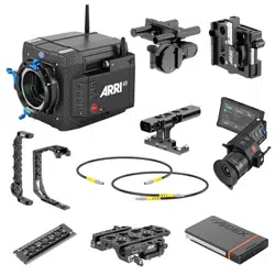
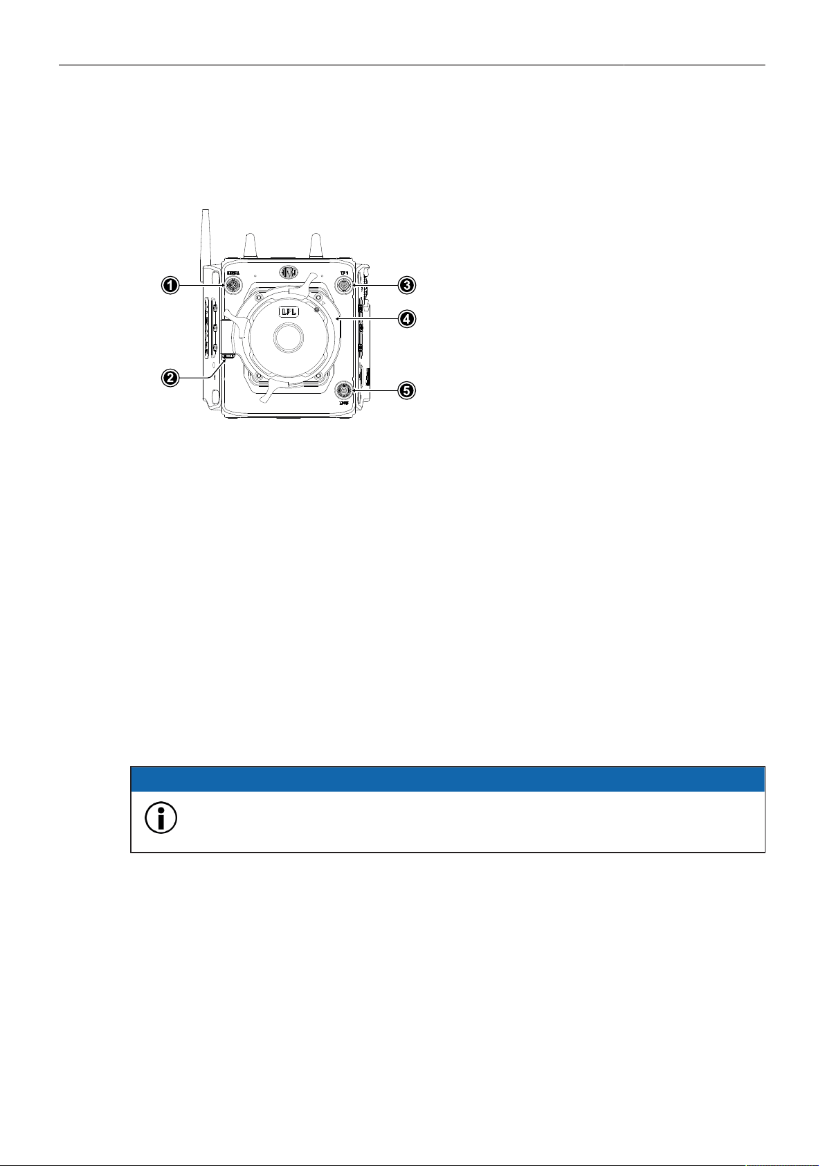
Camera Front
1
SERIAL Connector
2
LBUS Connector (on Lens Mount)
3
VF 1 Viewfinder Connector
4
Lens Mount (here: LPL Mount (LBUS))
5
LBUS Connector
SERIAL Connector (4-pin LEMO)
The SERIAL connector is used to connect distance measurement devices such as ARRI UDM-1, CE
CineTape Measure or Focus Bug directly to the camera and receives data from and provides power
to the distance measuring device. The SERIAL connector outputs regulated 12.0 V with a maximum
current of 200 mA.
VF 1 Viewfinder Connector (CoaXPress)
The camera uses an industrial CoaXPress interface with an ARRI custom connector to connect the
MVF-2 viewfinder with the camera. The interface transmits power, video and control data. The VF 1
connectors supports cable lengths of up to 5 m (16.4 ft). The VF connector supports hot plugging and
comes without a key, so the viewfinder cables plug in regardless of the connector's orientation.
LBUS Connector (4-pin LEMO)
Both LBUS connectors are used to connect daisy chainable LBUS devices of the ECS Electronic
Control System (lens motors, ARRI Master Grips, ARRI OCU-1, RIA-1...) to the camera and supply
regulated 24.0 V with a maximum current of 4.0 A.
ADVICE
Do not connect both LBUS ports (body and lens mount) of the ALEXA 35 in a daisy chain
and thus form a loop, you may experience problems such as the camera shutting down.
Camera Body Overview 10
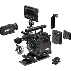
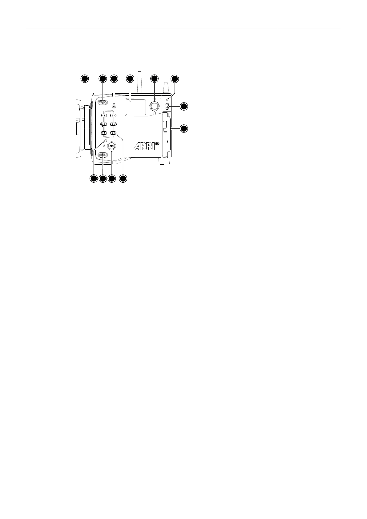
Camera Left
1
2
3
4
5
6
7
2
8
9
10
11
12
1
Lens Mount (here: LPL Mount (LBUS))
2
Mounting Points for Accessories
3
LOCK Button
4
Side Display
5
Side Display Jogwheel
6
Rear Camera Status LED
7
Left Camera Status LED
8
REC Button
9
User Buttons 1-6
10
POWER Button
11
Camera Identification Label
REC Button, LOCK Button & User Buttons 1-6
Use the REC button (8) to start and stop recording. Press and hold the LOCK button (3) to lock all
camera buttons. Besides the REC and LOCK button, the camera left is equipped with six freely
assignable user buttons (9). Each button can be customized with individual functions. Once a user
button is assigned with a function, press the button to trigger its function. An LED on each user button
reflects the functional status.
Camera Status LEDs
The camera status LEDs reflect the current camera state:
Off
Green
Orange
Red
Red / Green flashing
Idle. No recording media inserted or recording media full
Standby and ready to record
Prerecording
Recording
Error State
Side Display and Jogwheel
The side display provides control of basic camera parameters, recording media erase and can show
general information on the camera status. Use the jogwheel to navigate through screens and change
settings.
Media Door and Media Door Release
To access the media slot, slide the media door release towards the camera bottom so that the spring
loaded door jumps open.
Camera Identification Label
The camera serial number is located on the left side of the camera next to the media bay door. The
serial number consists of the last 5 digits of the product number K1.0039373-XXXXX.
Camera Body Overview 11
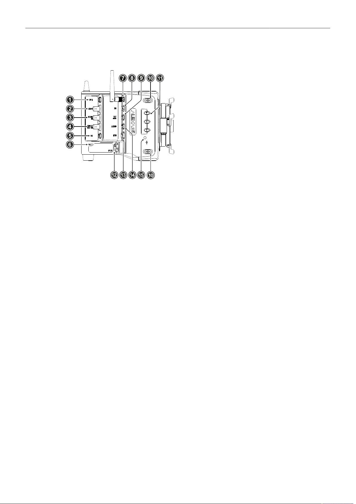
Camera Right
1
VF 2 Viewfinder Connector
2
SDI 1 Connector
3
SYNC IN Connector
4
SDI 2 / RET IN Connector
5
TC (Timecode) Connector
6
BAT LED
7
ECS White Radio Antenna Connector
8
RS Connector
9
12V Connector
10
Mounting Points for Accessories
11
User Buttons 7-9
12
PWR Connector
13
ETH Connector
14
AUDIO Connector
15
Right Camera Status LED
VF 2 Viewfinder Connector (CoaXPress)
VF 2 is the second viewfinder port. The camera uses an industrial CoaXPress interface with an ARRI
custom connector to connect the MVF-2 viewfinder with the camera. The interface transmits power,
video and control data. The VF 2 connector supports cable lengths of up to 10 m (33 ft). The VF
connector supports hot plugging and comes without a key, so the viewfinder cables plug in regardless
of the connector's orientation.
SDI 1 & SDI 2 / RET IN (BNC)
Both SDI BNC connectors can be configured to output the following video signals:
422 1.5G HD
422 3G HD
444 3G HD
422 6G UHD
422 12G UHD
444 12G UHD
(23.976, 24, 25, 29.97 and 30 fps progressive or psf) according to SMPTE ST 292-1:2012
(48, 50, 59.94 and 60 fps progressive) according to SMPTE ST 425-1:2014
(23.976, 24, 25, 29.97 and 30 fps progressive) according to SMPTE ST 425-1:2014
(23.976, 24, 25, 29.97 and 30 fps progressive) according to SMPTE ST 2081-10:2015
(48, 50, 59.94 and 60 frames fps progressive) according to SMPTE ST 2082-10:2015
(23.976, 24, 25, 29.97 and 30 fps progressive) according to SMPTE ST 2082-10:2015
The SDI 2 / RET IN connector can be configured in the camera menu to function either as SDI output or
as a Return In input, accepting 1.5G and 3G SDI signals.
SYNC IN (BNC)
The SYNC IN connector is a BNC connector for input of reference signals and accepts analog black
burst signals and tri-level HD signals for camera synchronization.
TC (5-pin LEMO)
The TC connector accepts and outputs LTC (Longitudinal Timecode) signals.
White Radio Antenna Connector (Female RP-SMA)
White radio allows for wireless lens control, lens data communication and remote control of camera
functions using the hand units of the ARRI Electronic Control System.
RS (3-pin Fischer)
The RS connector outputs regulated 24 V accessory power and can supply external devices with a load
of up to 3.0 A. Additionally, the RS connector outputs a shutter pulse signal and can be used to send a
remote start/stop signal to the camera.

Camera Body Overview 12
12V (2-pin LEMO)
The 12 V output with a 2-pin LEMO connector supplies accessories with regulated 12.0 V with a
maximum current of 2.0 A.
PWR (8-pin LEMO)
The PWR connector is the main power input for the ALEXA 35 and accepts an input voltage range from
20.5 to 33.6 V DC. You can use power cables KC50-S (K2.75007.0) or KC50-SP-S (K2.0001275) to
power the camera from an external source.
ETH (10-pin LEMO)
The ETH Ethernet connector is used for camera remote control, metadata streaming and service
purposes. It supplies regulated 24 V with a current of 0.5 A. Use the ALEXA Ethernet Cable KC 153-S
(K2.72021.0) to connect the camera to a standard RJ-45 Ethernet port.
AUDIO (6-pin LEMO)
The AUDIO connector is a 2-channel +24 dBu line level audio input with an additional regulated 12
V power output with a current of up to 0.5 A. Use the ALEXA Mini LF Audio connector with cable
(K2.0023988) to connect audio sources.
PWR and BAT Status LEDs
The BAT LED indicates the status of the power source connected to the BAT interface on the back
of the camera used for onboard batteries, the PWR LED indicates the status of the power source
connected to the PWR connector.
User Buttons 7-9
The camera right is equipped with three freely assignable user buttons (11). Each button can be
customized with individual functions. Once a user button is assigned with a function, press the button to
trigger its function. An LED on each user button reflects the functional status.
Camera Body Overview 13
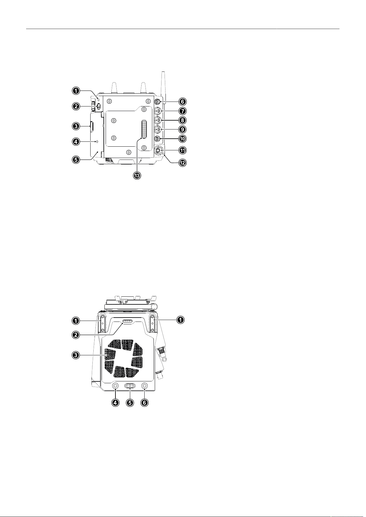
Camera Rear
1
Rear Camera Status LED
2
POWER Button
3
Media Door Release
4
Media LED Window
5
Media Door
6
VF 2 Viewfinder Connector
7
SDI 1 Connector
8
SYNC IN Connector
9
SDI 2 / RET IN Connector
10
TC (Timecode) Connector
11
PWR Connector
12
PWR Status LED
13
Camera Rear Interface
POWER Button
Press the POWER button to switch the camera on, press and hold the button to switch the camera off.
Camera Rear Interface
The rear interface of the camera is used to connect battery adapter plates and electronic accessories
such as the Power Distribution Module PDM-1 and the Audio Extension Module AEM-1. It supplies
power, receives and transmits audio signals, time code and serial data. The power output to the rear
interface pins is interrupted when no adapter or module is connected.
Camera Top
1
Mounting Points for Accessories
2
Top Connector
3
Fan Outlet
4
WiFi Antenna Connector
5
Mounting Point for Accessories
6
WiFi Antenna Connector
Top Connector
For future use.
WiFi Antenna Connectors (RP-SMA)
The camera is equipped with a 2.4 GHz WiFi module and two WiFi antennas, both located on the back
of the camera.
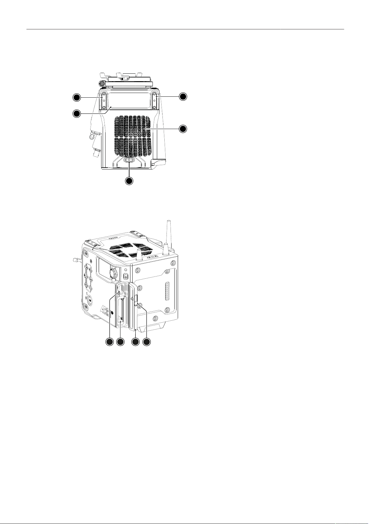
Camera Body Overview 14
Camera Bottom
1
2
1
3
4
1
Mounting Points for Accessories
2
Conformity Label
3
Fan Intake
4
Mounting Point for Accessories
Media Bay
1
2
3
4
1
USB-C Connector
2
Recording Media Slot
3
Media Door
4
Media Door Release
Recording Media Slot
The camera records onto Codex Compact Drives, using the media bay on the camera left side. A small
window in the media bay door shows the status LED of the Compact Drive. To access the media slot,
slide the media door release (4) towards the camera bottom so that the spring loaded door jumps open.
USB-C Connector
The camera saves data such as user setups, frame grabs and log files to USB-C memory sticks
formatted with exFAT file system. Software updates, additional frame lines and ARRI look files are
loaded onto the camera from the USB-C memory stick. The USB-C connector (1) can also be used to
charge USB devices and supplies 5.0 V with a maximum current of 1.5 A.
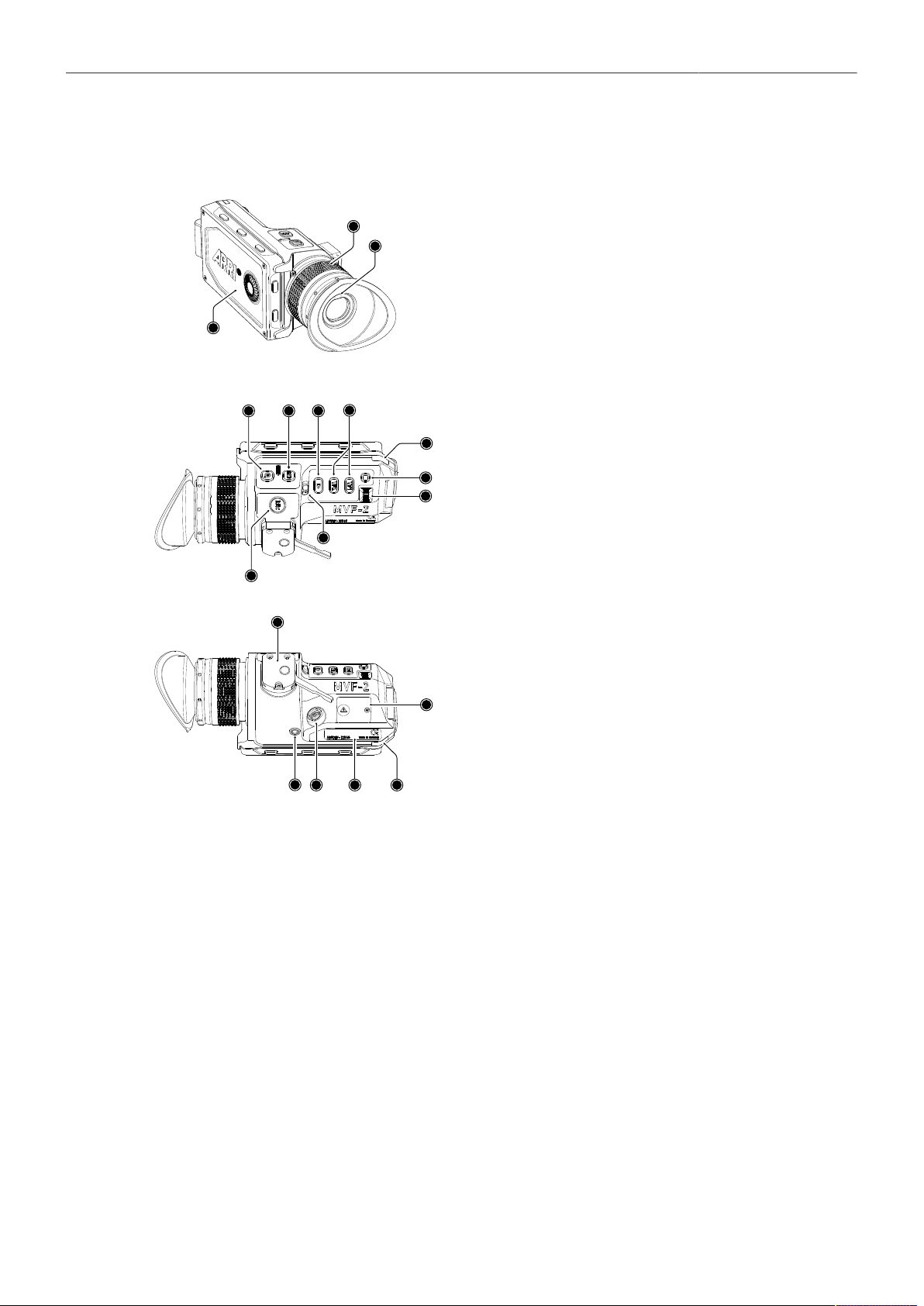
Multi Viewfinder MVF-2 Overview 15
5 Multi Viewfinder MVF-2 Overview
1
3
1
2
1
1
Flip-out Monitor
2
Diopter Adjustment
3
Proximity Sensor
12
4
5
6
7
8
9
10
11
4
ZOOM Button
5
EXP Button
6
PLAY Button
7
VF 1&2 User Buttons
8
Top Tally Light
9
SET Button
10
User Wheel
11
LOCK Switch
12
REC Button
13
14
15
16
17
18
13
Dove Tail
14
Service Cover
15
Bottom Tally Light
16
Product Label
17
Viewfinder Connector
18
Headphones Out
EVF OLED Display
The MVF-2 is equipped with a high contrast, temperature controlled 1920 x 1080 OLED display.
Diopter Adjustment
With the camera switched on and while looking into the viewfinder, twist the ring (2) left or right to adapt
the viewfinder image to your visual acuity. With the help of the scale labeled from 1 to 9 you can easily
remember your adjustment when different people are using the viewfinder. The diopter adjustment can
compensate from -5 to +5 diopters.
Proximity Sensor
This infrared sensor (3) automatically deactivates the MVF-2's internal OLED display when you
withdraw your eye to prevent burn-ins on the panel and activates it again as soon as you approach the
eyepiece. Do not permanently cover the sensor as this might cause irreversible burn-in on the OLED
display.

Multi Viewfinder MVF-2 Overview 16
ADVICE
Permanent Activation of the Viewfinder OLED Display
Permanent activation can cause irreversible burn-ins on the viewfinder OLED display.
Do not cover the viewfinder proximity sensor. When covered, the viewfinder OLED display will be
switched on permanently.
If you need to cover the viewfinder, disable the viewfinder OLED display first using the EVF
Power setting.
When shooting in hot environments, make sure to have the viewfinder mounted on the viewfinder
bracket to ensure proper cooling.
If the viewfinder is used as a remote control without standing support, turn off the viewfinder
OLED display using the EVF Power setting.
Built-in Eyepiece Heater
The MVF-2 is equipped with a built-in eyepiece heater to prevent fogging of the eyepiece when
shooting in cold environments. The eyepiece heater can be activated in the camera menu and only
becomes active when the eyepiece has a temperature of 15 °C (59 °F) or below. In extremely cold
environments please use the Heated Eyecup HE-7.
EXP Button
The EXP button (5) activates and deactivates the False Color exposure tool for the EVF and the flip-out
monitor.
ZOOM Button
Pressing the ZOOM button (4) activates the zoom feature on EVF and the flip-out monitor for a
temporary zoom-in to quickly check focus. The magnification ratio is 1:1, or one sensor photosite to one
display pixel.
PLAY Button
Press and hold the PLAY button (6) for two seconds to start in-camera playback from the recording
media.
VF 1 and VF 2 User Buttons
The MVF-2 has two user buttons, VF1 and VF2 (7). You can assign a frequently used function to each
button.
SET Button and User Wheel
The SET button and the user wheel (9, 10) provide the same functionality as the jogwheel on the flip-
out monitor (see next chapter) and can be used for menu navigation and adjustment when the flip-out
monitor is used with the display visible in the folded-in position.
LOCK Switch
The LOCK switch (11) locks all MVF-2 buttons. A dedicated lock icon is displayed on the HOME screen
as well as in the Status Info of the EVF.
REC Button
The REC button (12) starts and stops recording to the recording media. With no recording media
inserted, the button is inactive.
Multi Viewfinder MVF-2 Overview 17
Product Label
The product label (16) shows the MVF-2 serial number. The serial number consists of the last 5 digits of
the product number K1.0024074 - XXXXX.
Viewfinder Connector
The ALEXA 35 uses industrial CoaXPress interfaces with a custom ARRI connector to connect the
MVF-2 viewfinder with the camera. The interface transmits power, video and control data and supports
cable lengths of up to 10 m (33 ft). The VF connector (17) comes without a key, so the VF cables plug
in regardless of their orientation and support hot plugging of the viewfinder.
Headphones Out
The headphones out (18) is a 3.5 mm TRS connector (headphone jack), which outputs all four audio
channels with a maximum power of 2.5 dBm.
Flip-out Monitor
The 4“ flip-out monitor with up-and-down tilt function can display the camera live image or the main
user interface (HOME screen and camera menu).
2
3
4
5
1
1
Jogwheel
2
HOME / LIVE Button
3
MENU / BACK Button
4
Upper Screen Buttons
5
Lower Screen Buttons
Jogwheel
The jogwheel (1) is used to
► Scroll or navigate through lists and menus
► Change values (by scrolling up or down)
► Access and confirm settings (by pressing the jogwheel center)
HOME / LIVE Button
The HOME / LIVE button (2) toggles to display either the HOME screen (shown in the image above) or
the camera live view.
MENU / BACK Button
Pressing the MENU / BACK button (3) while in the HOME screen or in camera live view opens the
camera menu. While in the camera menu, it serves as a BACK button.
Screen Buttons
The MVF-2 flip-out monitor has six screen buttons, three above (4) and three below (5) the screen.
Their function depends on the screen content and is labeled directly below or above each button.
Unlabeled buttons do not have a function for that screen. A grayed-out label indicates that the function
is currently not available.
Multi Viewfinder MVF-2 Overview 18
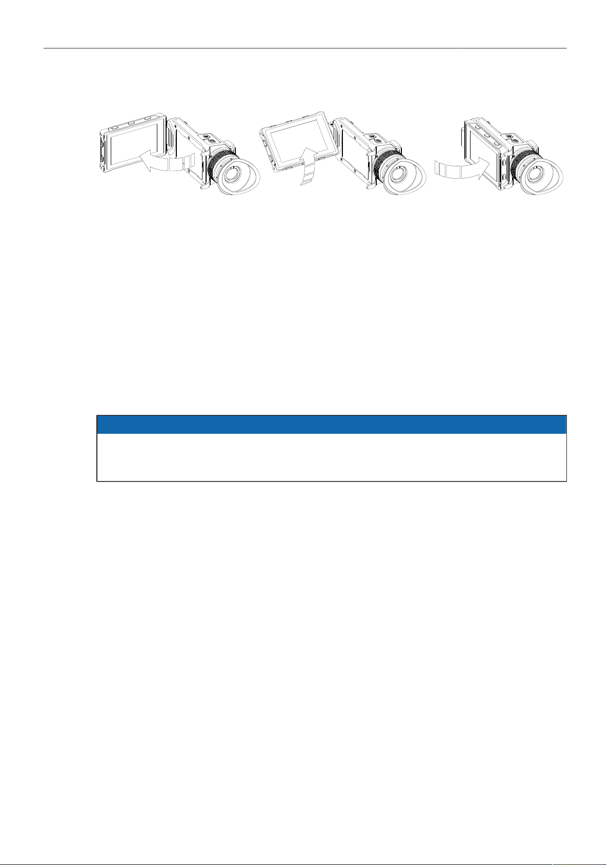
Adjusting the Flip-out Monitor
Fold out, swivel and fold in the monitor to put the display visible in the folded-in position. The image on
the monitor automatically adjusts its orientation, or can be set to the desired orientation in the camera
menu.
Viewfinder Cables
MVF-2 viewfinder cables are available in the following lengths:
ID No.
K2.0042857
K2.0023944
K2.0023945
Length
0.5m (1.5 ft)
2.0 m (6.5 ft)
10.0 m (33 ft)
Description
Standard cable with right angle connector
The medium length for remote use (straight connector)
The longest possible length for remote use (straight connector)
ADVICE
Although the camera is equipped with two viewfinder ports, two viewfinders cannot be operated in
parallel. When two viewfinders are connected to the camera, the second connected viewfinder only
displays a boot screen, but does not become active.
Power Supply 19
6 Power Supply
ADVICE
Always keep the PWR connector accessible so that the cable can be unplugged quickly in case
of emergency.
Unplug the power cable by gripping the power plug, not the cable.
Do not use power cables longer than 4m.
Operate the system using only the type of power source indicated in the manual.
Do not supply power outside the specified voltage range.
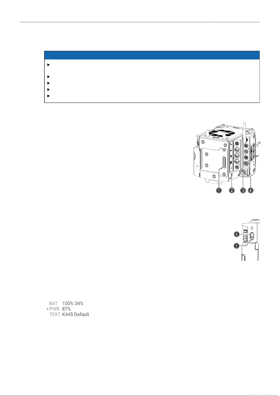
Power Inputs
The camera accepts input voltages from 20.5 to 33.6 V DC.
The BAT input is located on the rear interface (1) and is used to
power the camera from 24 V onboard batteries using a battery
adapter.
The LEMO 8-pin PWR input (3) allows to power the camera
from block batteries or DC power supplies using cables KC50-S
(K2.75007.0) or KC50-SP-S (K2.0001275).
Both inputs are equipped with an LED (2, 4) that indicates the
status of the input.
Switching On and Off
The POWER button (5) is located at the rear left of the camera. The POWER but-
ton's background light is illuminated when the supplied power is in the valid range.
While the camera is booting up, the boot status LED (6) is flashing blue. As soon as
the camera has finished the boot process, the boot status LED turns to solid blue.
► To switch on the camera, press the POWER button.
► To switch off the camera, press and hold the POWER button until the camera has
switched off.
Status Information
The status of the power inputs is displayed on the HOME screen of the MVF-2 and the side display as
well as in the Status Info.
When power is supplied through both the PWR and BAT input, a current
symbol on the HOME screen indicates which input is being used. The pre-
ferred input to be used can be set in the camera menu.
The BAT entry can display two values when two B-mount batteries are used together (e.g. a hot swap
unit and a main unit). The first value refers to the battery that sits directly on the battery adapter (usu-
ally the hot swap unit), the second value refers to the stacked battery. The camera will always draw
power from the stacked battery first.

Power Supply 20
Additionally, the battery status can be read direct-
ly from the camera body via the two status LEDs
(2, 4). The LEDs indicate which input is in use and
whether sufficient power is available. A green LED
indicates that the input is in use, a blue LED indi-
cates that there is power at the input, but it is not
in use. The power low warning is issued when the
supply voltage is lower than 22.0 V.
Power Outputs
The main accessory outputs of the camera are the RS output and the 12 V output. In addition,
appropriate accessories can be powered via the LBUS sockets, the ETH socket, the SERIAL socket
or the AUDIO socket. The optional Power Distribution Module PDM-1 adds seven additional power
outputs (4x 24 V, 2x 12 V, 1x 12 V Twist D-Tap) to the camera.
24 V Outputs RS
LBUS
ETH
24 V (PDM-1)
(3.0 A max.)
(4.0 A max.)
(0.5 A max.)
(4.0 A max.)
12 V Outputs 12 V
AUDIO
SERIAL
D-Tap (PDM-1)
(2.0 A max.)
(0.5 A max.)
(200 mA max.)
(2.0 A max.)
The total available power over all 24 V out-
puts is just below 100 W to be compliant with
DIN EN 62368 PS2, with a max. current of
4.0 A.
The total available power over all 12 V outputs is
50 W, with a max. current of 2.0 A.
Power Consumption
The ALEXA 35 draws between 85 W and 135 W while recording, depending on the set recording
resolution and sensor frame rate (with MVF-2 connected, but no further accessories attached).
The camera will switch off at 19.5V supply level.
Input Priority
In case both power inputs are used, the camera supports to set which input is to be used preferentially.
► Select MENU > System > Power > Priority to set the power input priority.
Following options are available:
Power In (PWR)
Onboard Battery (BAT)
Highest Voltage
Always use the PWR input when power is available on BAT and PWR.
Always use the BAT input when power is available on BAT and PWR.
Use the input supplying the higher voltage.
Power Warning
For each power input, a threshold can be set at which a battery warning is triggered. When the
threshold is reached, the battery values on the HOME screen as well as in the Status Info blink orange.
► Select MENU > System > Power > Power In (PWR) Warning (%) to set the warning threshold (%)
for the PWR input.
► Select MENU > System > Power > Power In (PWR) Warning (V) to set the warning threshold (Volts)
for the PWR input.
► Select MENU > System > Power > Onboard Battery (BAT) Warning (%) to set the warning threshold
(%) for the BAT input.

Power Supply 21
► Select MENU > System > Power > Onboard Battery (BAT) Warning (V) to set the warning threshold
(Volts) for the BAT input.
Info: When using two B-Mount batteries simultaneously, the BAT warning will not be issued until
both batteries have reached the warning threshold.
BAT Unit Preference
The status of the power inputs can be displayed either in Volt or as a percentage of total battery
capacity.
► Select MENU > System > Power > BAT Unit Preference to set the preferred unit between Volt and
Percent.
Info: Percentage can only be displayed if supported by the power source.
PWR/BAT LEDs
In case the status display via the two power LEDs is not needed, both LEDs can be switched off.
► Select MENU > System > Power > Enable PWR/BAT LEDs to activate / deactivate PWR/BAT
LEDs.
BAT Auto Boot Up
When the camera was switched off due to a power cut, it automatically boots up as soon as power is
present again. This behavior is optional for the BAT input, e.g. to avoid power cycling with flat batteries.
► Select MENU > System > Power > BAT Auto Boot Up to enable / disable automatic boot up for the
BAT input.
Menu Operation 22
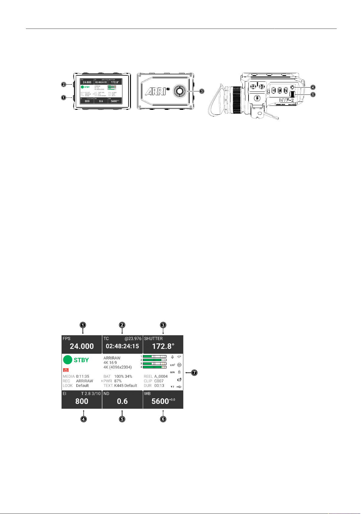
7 Menu Operation
1 MENU / BACK Button
2 HOME / LIVE Button
3 Jogwheel
4 SET Button
5 User Wheel
► Press the MENU / BACK button (1) on the MVF-2 to access the camera menu.
► Rotate the jogwheel (3) or the user wheel (5) to scroll up or down to select the desired menu entry:
Entries with a “>” at the end navigate to a sub menu. To navigate to a sub menu press the jogwheel
center or the SET button (4). To return to a higher menu level press the MENU / BACK button.
Entries with a value allow for direct editing. To edit a value press the jogwheel center or SET button,
then rotate the jogwheel or user wheel to select the desired value. Press the jogwheel center or
SET button to confirm the change or press CANCEL to discard.
Entries with a check box allow for direct activation/deactivation. Press the jogwheel center or SET
button to activate/deactivate the setting.
► To leave the menu press the HOME / LIVE button (2).
The jogwheel and the user wheel + SET button provide identical functionality.
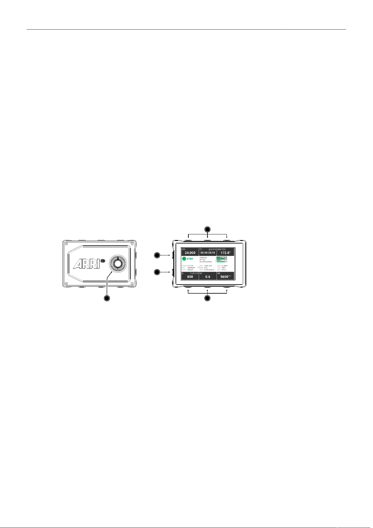
7.1 HOME Screen
The HOME screen shows the most important camera settings and gives quick access to changing them
through the screen buttons.
1
FPS Sensor Frame Rate Settings
2
TC Timecode Settings
3
SHUTTER Settings
4
EI Exposure Index Settings
5
ND Filter Settings
6
WB White Balance Settings
7
Status Section
FPS (Sensor Frame Rate)
The FPS label shows the current sensor frame rate in frames per second. Press the FPS screen button
to adjust the sensor frame rate. The FPS label turns orange if the sensor frame rate does not match the
project frame rate.

Menu Operation 23
TC (Timecode)
The TC label shows the current timecode value and project rate. Press the TC screen button to access
the timecode settings. The TC label turns orange if a timecode misconfiguration exists. Press the TC
screen button for more information.
SHUTTER
The SHUTTER label shows the current shutter angle or exposure time. Press the screen button to set
the shutter of the sensor. The shutter unit can be set to display either shutter angle (5.0° to 356.0°) or
exposure time (1 second to 1/8000 seconds). The maximum shutter angle is limited by the resulting
exposure time (1 second max.). Shutter angle and sensor frame rate determine exposure time of the
sensor in seconds by the following equation: exposure time = shutter angle / (360 x FPS).
EI (Exposure Index)
Shows the current exposure index. Press the screen button to adjust the exposure index in a range
from 160 to 6400 ASA without Enhanced Sensitivity Mode or 2560 to 6400 ASA with Enhanced
Sensitivity Mode.
ND Filter
The ND label shows the current ND filter value of the built in FSND (Full Spectrum Neutral Density)
filter stage. Press the screen button to change the ND filter.
WB (White Balance)
The WB label shows the current white balance and tint. Press the screen button to set the white
balance. This is the color temperature of the light source that the camera is currently adjusted for. In
addition to the red/blue correction of the white balance, the camera can also compensate for a green/
magenta tint. This value, called CC (color compensation), is shown as an exponent of the WB value.
Positive values are marked with a “+” and negative values with a “-”.
White balance can be adjusted from 2000 to 11000 Kelvin (here: 5600) in steps of 10 K for red/blue
correction. Color compensation for green/magenta tints can be adjusted in a range from -16.0 to +16.0.
Positive or negative CC color compensation values then appear as an exponent of the WB value (here:
+0.0).
Status Section
The status section on the home screen shows key data about recording, power supply, remaining
media capacity and more:
Camera Status
STBY
PREREC
REC
PLAY
ERASE
None
ERROR
Standby - ready for recording.
Prerecording.
Recording.
Camera is in playback mode.
Medium erase in progress. Active erasing disables recording.
Idle, recording not possible (e.g. no media inserted, media is full).
System error occured. See MENU > Alerts for details.
Codec, Sensor Mode & Recording Resolution
Currently set codec, sensor mode and recording resolution.
Audio Meters
The audio meters are only displayed when audio recording is enabled. When audio recording is dis-
abled, a crossed out speaker icon is displayed. Black markers are shown at signal levels -20, -18, -9
dBFS. The yellow marker at -5 dBFS and the red marker at -2 dBFS indicate a signal close to clipping.
Menu Operation 24
Clip Information
Displays the current reel name, the current clip number and the duration of the current clip (while record-
ing) or of the last recorded clip (during standby).
Battery Status and Texture
Displays the status of the power inputs and the active texture.
Media Capacity & Recording and Look Settings
Displays the remaining capacity of the recording medium, the active recording processing (ARRIRAW or
LogC4) and the active look file.
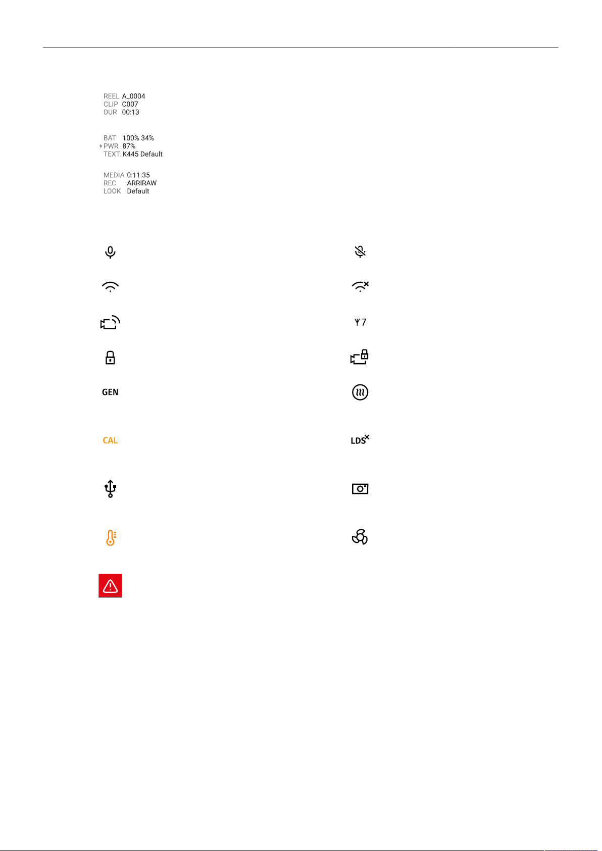
Status Icons:
The microphone icon indicates that the internal
microphones are active.
Internal microphones are muted.
WiFi is active and in client mode. The camera
is connected to a network.
WiFi is active and in client mode. The camera
is not connected to a network.
WiFi is active and in host mode.
The ARRI ECS White Radio is active and uses
the displayed channel number.
MVF-2 Lock Icon. MVF-2 buttons are locked. Camera Lock Icon. Camera buttons are locked.
The Genlock icon indicates that the camera is
synchronized to a Genlock or timecode signal.
The icon turns orange when the source signal
is missing or is not usable.
The MVF-2 eyepiece heater is on. The icon
turns gray when the heater is not heating (eye-
piece temperature is > 15 °C (59 ° F)).
The CAL icon indicates that a lens motor cali-
bration is required. The icon turns black when
calibration is in progress and expires when cal-
ibration has finished.
Indicates that the LDS interface is disabled.
The USB icon indicates a connected USB
medium. The icon turns gray when the medium
is read only, and orange if the medium is not
usable.
The Frame Grab icon indicates active frame
grabbing. The icon turns orange if frame grab-
bing failed (e.g. no USB medium is inserted).
The temperature icon indicates that the camera
temperature is increased. The icon turns red
when the camera temperature is out of range.
The fan icon indicates that the camera needs
to increase the fan speed above 20 dB noise
emission level. The icon turns orange when the
fan speed exceeds 20 dB.
Indicates an active alert state. See MENU > Alerts for detailed information.
Menu Operation 25
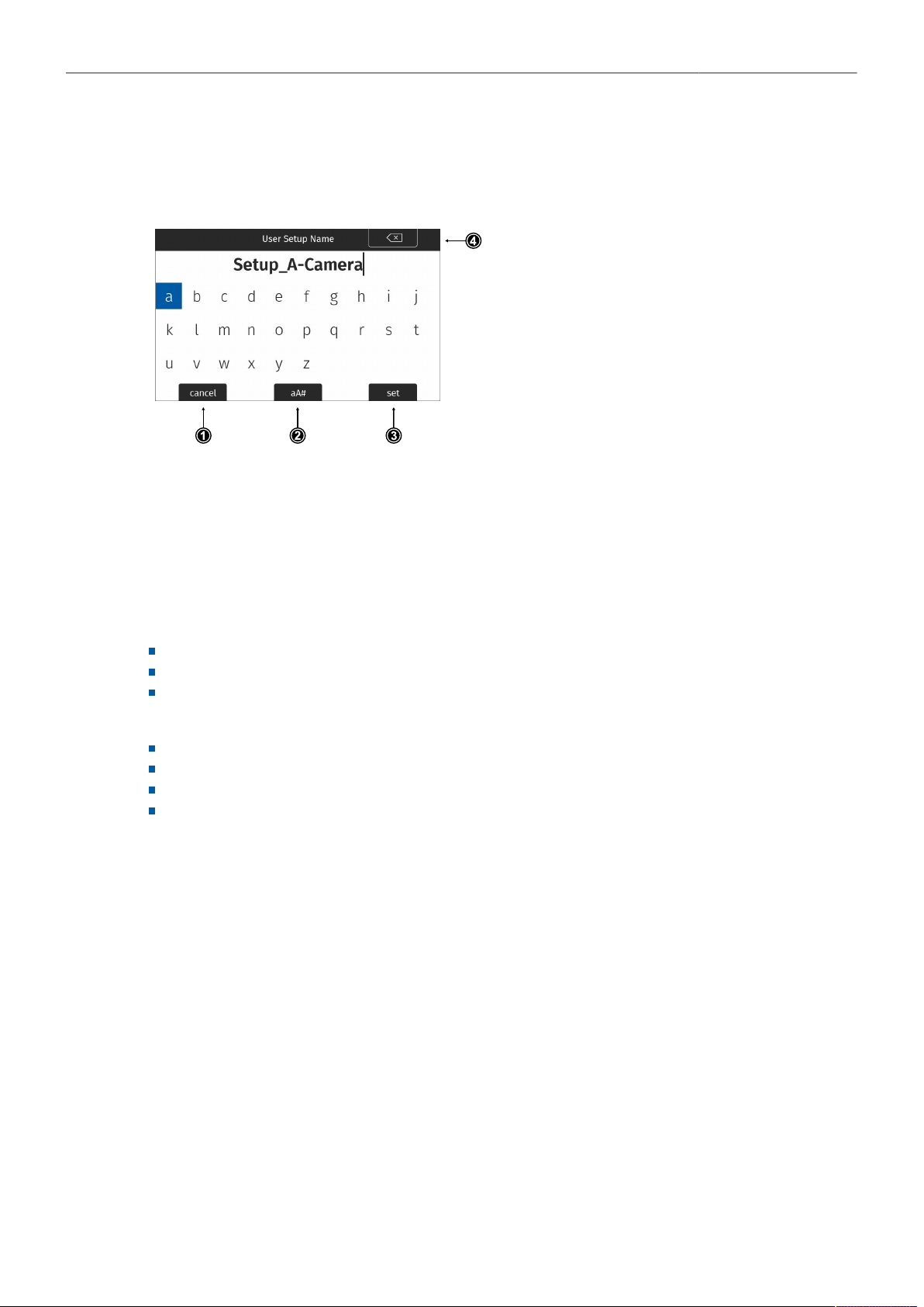
7.2 On-screen Keyboard
When working with textual parameters on the camera, an on-screen keyboard serves to enter text. You
need to use the keyboard, for example, to enter the name when saving a user setup.
► Use the jogwheel to select and enter charac-
ters.
► The CLEAR button (4) deletes the digit to the
left of the cursor. Press and hold the button to
clear the entire value.
► The aA# button (2) toggles between lower
case, upper case and numeric text entry.
► Press the SET button (3) to save the file, or
the CANCEL button (1) to exit.
7.3 Working with Lists and Importing Files
For certain parameters, the camera menu operates with preset lists that come with a default content
and that can be adjusted to the user's preference. You can add values to and delete values from these
lists, so that only project relevant values are displayed. Value based lists contain entries that can be
edited directly in the camera (e.g. Shutter and White Balance presets) while file based lists contain files
that are installed on the camera or were imported from the USB medium (e.g. Looks and Frame Lines)
Following parameters work with value based lists:
HOME > FPS
HOME > SHUTTER
HOME > WB
Following parameters work with file based lists:
MENU > Image > Look > Look
MENU > Monitoring > Frame Lines > Frame Line
MENU > Setups > User Setups Installed
MENU > Lens & ECS > Lens Data > Lens Tables Installed
Menu Operation 26
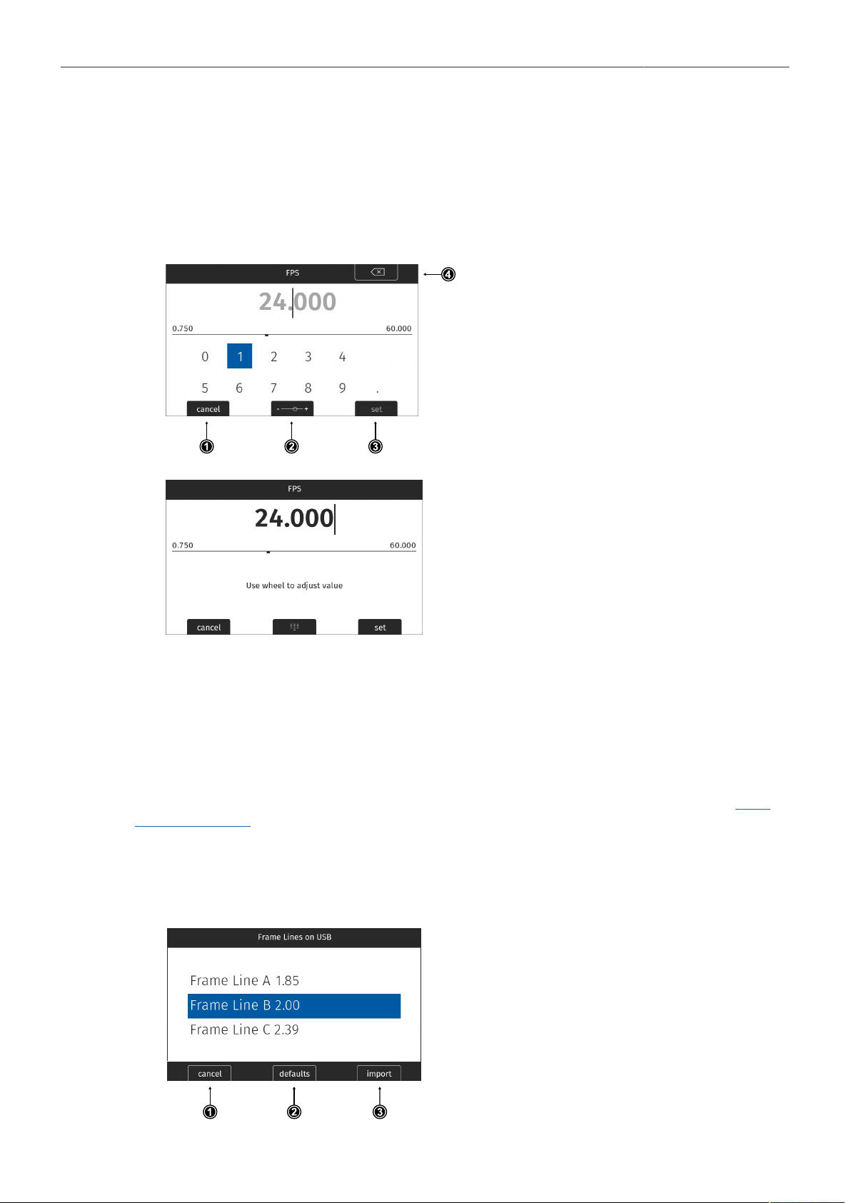
Adding Entries to Value based Lists
The camera offers two methods of input when adding entries to a list. The numeric keyboard is
intended to be used for direct input of a value while the jogwheel mode is intended to be used for
fine tuning a value (for example to fine adjust the shutter when filming monitors). The minimum and
maximum possible values are shown in the middle of the screen above the horizontal line.
► Select e.g. HOME > FPS > ADD.
► Press the MODE button (2) to switch be-
tween the numeric keyboard and the jog-
wheel mode.
► The numeric keyboard offers to directly en-
ter a value. Use the MVF-2 jogwheel to se-
lect and confirm digits.
► The CLEAR button (4) deletes the digit to
the left of the cursor. Press and hold the
button to clear the entire value.
► The jogwheel mode allows to fine adjust
values. Rotate the MVF-2 jogwheel to fine
tune the value.
► Press the MODE button (2) to if you need to
switch back to the numeric keyboard.
► Press the SET button (3) to add the new value to the presets list, or the CANCEL button (1) to exit.
Info: the SET button will be grayed out and the value displayed in red if the entered value is out of
range.
Importing Files
For looks, frame lines, user setups and lens tables the camera offers the option to import files from
the USB medium as well as from a factory default presets. To import files from a USB medium into
the camera, the USB medium needs to be prepared with a certain folder structure, see chapter "User
Storage Handling" for more information. The maximum file name length allowed is 64 characters
including the file extension. Files with a name exceeding 64 characters cannot be displayed in camera
lists. Special characters <, >, :, “, /,\, | and * in file names are displayed and replaced with a ”?“ in the
camera menu.
► Select e.g. MENU > Monitoring > Frame Lines > Frame Line > ADD.
► Select a frame line file to import from the
USB list or select DEFAULTS (2) to select a
frame line file from the factory defaults list.
► Press the IMPORT button (3) or the jog-
wheel to add the selected frame line to the
frame lines list, or the CANCEL button (1) to
exit.

Menu Operation 27
Deleting List Entries
► Select e.g. HOME > FPS.
► Scroll to the entry to be deleted.
► Press the DELETE button.
The selected entry is marked for delete.
► Press the DELETE button again to delete the selected entry or rotate the jogwheel to cancel.
Maximum Entries per List
All lists have a maximum number of entries they can hold. Whenever a list is full, the ADD button is
grayed out and a message is shown. You need to delete entries from the list first in order to add new
ones.
The following table lists the maximum number of entries for each type of list:
List
Max. Entries
FPS, Shutter
16
User Setups
20
White Balance
32
Looks, Textures
50
LDA
200
Frame Lines
256
Menu Operation 28
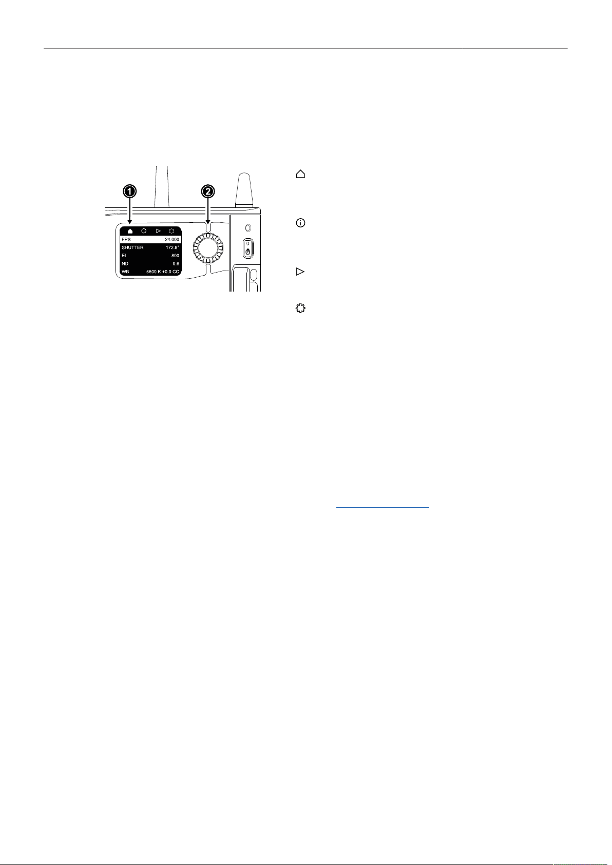
7.4 Side Display
The side display of the camera provides access to the main parameters. This can be useful for
applications where it is not necessary or possible to connect an MVF-2. The display is divided into four
pages, which can be switched between via the navigation bar at the top of the screen:
The Home Page (1) offers to adjust the main parame-
ters Sensor FPS, Shutter, Exposure Index, ND Filter
and White Balance.
The Info Page provides an overview about other im-
portant parameters such as the remaining time of the
recording medium or the set Look and Texture.
The Playback Page offers a simple in-camera play-
back control.
The Settings Page offers to adjust settings for the
side display and camera body and to erase the
recording medium.
Menu Operation
► Rotate the side display jogwheel (2) to select between pages.
► Press the jogwheel to access a page.
► Rotate the jogwheel to scroll up or down within the page.
► To edit a setting (Home Page and Settings Page), press the jogwheel, then rotate to select the
desired value. Press to confirm the change.
► To leave a page, scroll up into the navigation bar and press the jogwheel.
For playback control via the side display, please see "Playback", Page 62.
Display Mode
► Select SETTINGS > Display Mode.
Following options are available:
On
Off
The side display is always switched on.
The side display is switched off. Press and hold the jogwheel for 2 seconds to switch it back on.
Alternatively, the side display can be switched off by pressing and holding the jogwheel for 2 seconds.
Sleep
ND
The side display switches to sleep after 20 seconds of non-use. Reactivate by using the jogwheel.
The side display switches to sleep after 20 seconds of non-use and displays the current ND Filter value.
Reactivate by using the jogwheel.

Menu Operation 29
7.5 User Storage
The camera saves data such as user setups and frame grabs to a USB-C
memory stick. Look files, frame lines and software updates can be loaded
into the camera from the memory stick.
The USB-C slot (1) is located behind the media door, above the record-
ing media slot. Slide down the media door release (2) to open the media
door.
The camera supports exFAT formatted memory sticks using one partition
within a Master Boot Record (MBR) partition table and a maximum ca-
pacity of 256 GB. A special folder structure is used in order to work with
the camera.
Prepare Folder Structure
The camera can only load files from a correctly prepared USB medium with the required folder
structure. Preparing the folder structure on the USB medium within the camera will not alter existing
folders and files on the USB medium.
► Open the media door and insert the USB medium.
► Select MENU > Media > Prepare USB Medium to create the ALEXA 35 folder structure on the USB
medium:
ARRI/ALEXA35/ FRAMELINES
GRABS
LDA
LICENSES
LOG
LOOKFILES
SETUPS
SUP
SENSOR
TEXTURES
For frame line imports to camera
For stored frame grabs
For lens table import/export
For license file installation
For exported camera logfiles
For look file import/export
For import/export of user setups
For software update installation
For import/export of User Pixel Mask files
For Texture import
The USB icon on the HOME screen and in the Status Info indicates a connected medium.
A gray icon indicates that the medium is read only. An orange icon is displayed if the medi-
um is not supported.
USB Info
► Select MENU > Info > USB Info for additional information on the USB medium.

Menu Operation 30
7.6 Info Screens
The INFO screens provide detailed information about the current state of the camera system.
► Select MENU > Info.
The Info sub menu contains the following lists:
Version Info
Software
Revision
FPGA
MVF-2 Software
Lens Mount Software
The camera software version.
Revision of camera software version.
Firmware version of active FPGA.
Software version of MVF-2.
Software version of lens mount.
System Info
Time + Date
Camera Serial No.
Operating Hours
Sensor Temperature
Sensor Temp. State
Camera Temp. State
Current system time and date of the camera.
Serial number of camera.
Total operational time of the camera in hours:minutes.
Current temperature of image sensor.
Rates the sensor temperature according to OK, warning, or error.
Rates the camera temperature according to OK, warning, or error.
False Color Info
The False Color Info displays a reference chart explaining the color coding used for the False Color
exposure tool.
PWR/BAT LED Info
The PWR/BAT LED Info displays a reference chart explaining the LED states of the PWR and the BAT
LEDs.
Media Info
Status
Model
SN#
FW Version
Capacity
Clip Count
Status of the recording medium.
Name/model of the recording medium.
Serial number of the recording medium.
Firmware version of the recording medium.
Total storage size of the recording medium.
Number of clips on the recording medium.
USB Info
Status
Storage Free/Total
Frame Line Files
License Files
Look Files
Setup Files
SUP Files
LDA Files
Texture
Status of USB medium.
Free and total available storage on USB medium in megabyte.
Number of frame line files on USB medium.
Number of license files on USB medium.
Number of look files on USB medium.
Number of user setup files on USB medium.
Number of SUP (Software Update Package) files on USB medium.
Number of LDA (Lens Data Archive) files on USB medium.
Number of Texture files on USB medium.
Info: The number entries consist of two numbers, the number of files on the USB medium
and the number of files recognizable by the camera.

Menu Operation 31
Network Info
WiFi Network
WiFi IP
LAN IP
Web Remote
Streaming Addressing
Streaming Address
Streaming Port
Name of connected network (client mode).
IP address of the camera via WiFi.
IP address of the camera via Ethernet.
URL address of camera remote control website.
Type of addressing used for metadata streaming (Unicast / Multicast).
IP address of the metadata streaming receiving device.
Metadata streaming port.
Lens Info
Lens Type
Model
Serial No.
Extender
Focal Length
Focus
Iris
Type of lens (LDS, Cooke, ENG, EF).
Lens model name according to manufacturer.
Serial number of lens.
Name of extender (if used).
Focal length of lens in mm.
Current focus distance of lens.
Current iris value of lens.
User Button Info
The user button info screen lists the functions assigned to the user buttons of the camera body and the
MVF-2.
Export HW Info File
HW (HardWare) Info files are required to generate licenses in the ARRI License Shop or may be
requested by camera service to get detailed information on the camera's hardware and components
revisions.
The HW Info file will be exported to the USB medium in the ARRI/ALEXA35/LICENSES folder.
Export Logfiles
Logfiles help ARRI camera service to analyze potential problems. In normal circumstances, logfile
export is not required.
Export Logfiles combines the camera logfiles, HW Info file, current user setup and other diagnostic
files into a .zip archive and stores the archive in the ARRI/ALEXA35/LOG folder on the USB medium.
Privacy sensitive information such as WiFi password and look files are not exported.
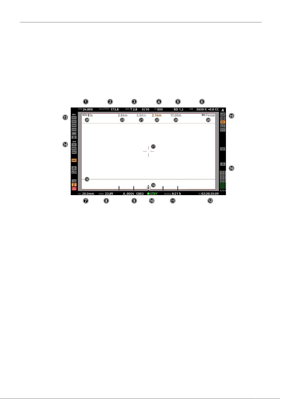
Status Information and Overlays 32
8 Status Information and Overlays
The camera displays camera status information on the EVF and the SDI outputs. At the top and bottom
of the screen, the camera displays status information in text form. The top status bar displays the
current settings of sensor FPS, shutter angle, exposure index, ND filter, and white balance. The bottom
status bar displays information about the battery level, reel and clip, camera status, remaining recording
time, and timecode. On the left and right side of the screen, icons provide information about the current
status of the camera. Furthermore, additional overlays such as lens data and an electronic horizon can
be displayed.
Status Info Top
1
2
3
Display of the set sensor frame rate. The FPS label turns orange if the sensor frame rate does not match the project rate.
Display of the set shutter (shutter angle or exposure time).
Display of the lens iris, including fractions of a stop (if lens data is available).
When using a lens extender, the iris value is displayed in brackets (recalculated value).
4
5
6
Display of the set exposure index.
Display of the set ND filter. The value is blinking while the filter changes.
Display of the set white balance.
Status Info Bottom
7 Display of the focal length of the lens (if lens data is available).
When using a lens extender, the focal length value is displayed in brackets (recalculated value).
8 Displays the active power source (onboard battery (BAT) or power in (PWR)) and its supply level. If the level reaches the
configured warning threshold, the value starts flashing orange.
9 Display of the current reel and clip number.
10 Display of the camera status:
STBY
PREREC
REC
PLAY
ERASE
None
ERROR
Standby - ready for recording.
Prerecording.
Recording.
Camera is in playback mode.
Medium erase in progress. Active erasing disables recording.
Idle, recording not possible (e.g. no media inserted, media is full).
System error occured. See MENU > Alerts for details.
Status Information and Overlays 33
11 Display of the remaining capacity of the recording media at current sensor frame rate and codec, in real time. When media
capacity is less than two minutes, capacity values starts flashing orange.
12 Display of the current timecode. The TC label turns orange if the sensor frame rate does not match the project rate.
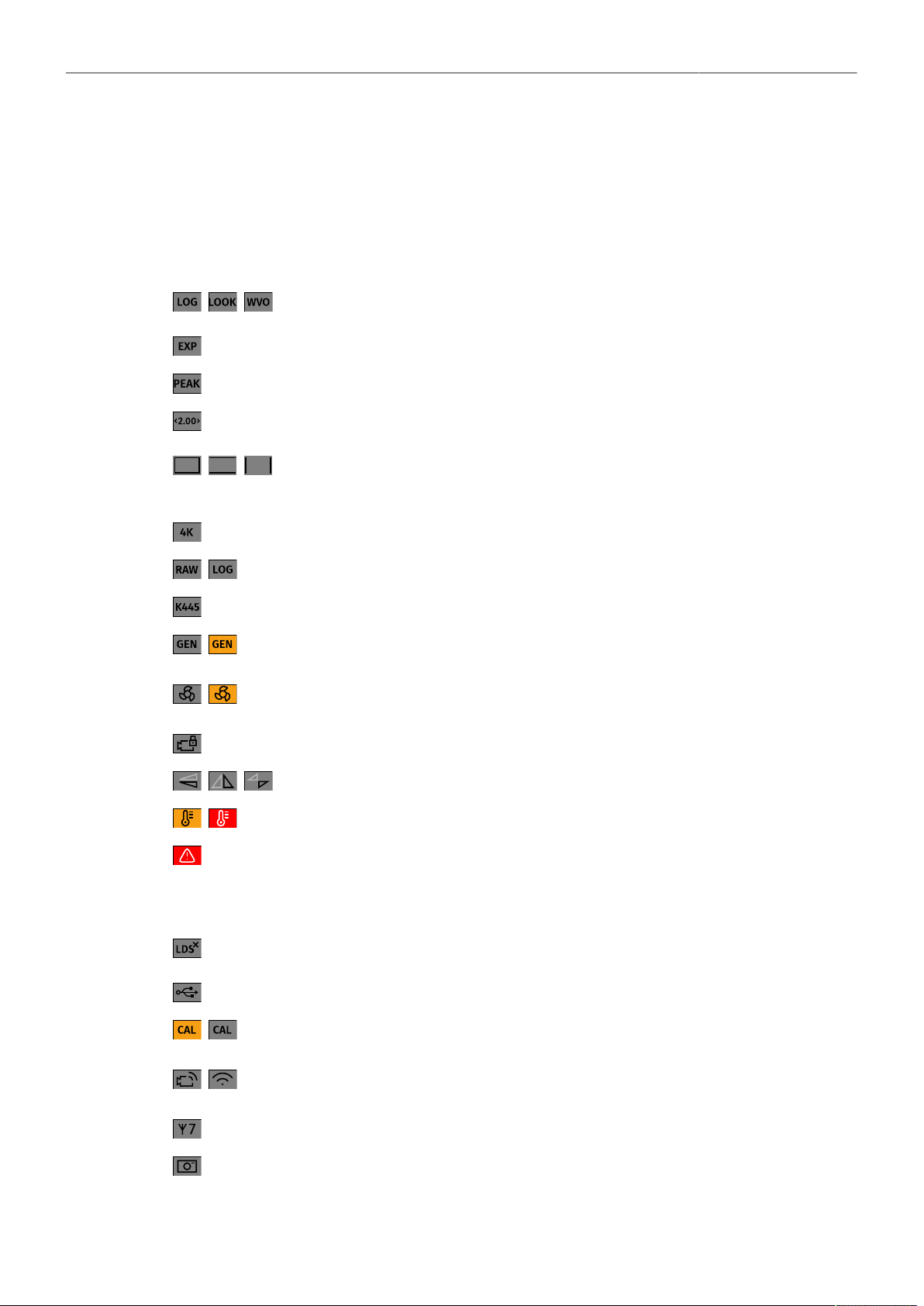
Status Info Left
13 EVF / SDI 1 / SDI 2 Status
Output processing icons. Shows the current processing for the respective output (LogC4, Look or
Wireless Video Optimized for LogC4).
Exposure tool icon. Indicates that False Color is active on the respective output.
Peaking Icon. Indicates that Peaking is active on the respective output.
Anamorphic Desqueeze icon. Indicates that Anamorphic Desqueeze is active and which lens
squeeze factor is applied.
Magnification icons. Indicate that the output shows less image content than actually recorded.
14 Camera Status
Shows the current Recording Resolution (4.6K, 4K, UHD, 3.3K, 3K, 2K, HD)
Shows the current recording processing (RAW for ARRIRAW, or LOG (LogC4) for Apple ProRes).
Shows the currently set Texture.
Genlock icon. Indicates that the camera is synchronized to a Genlock or timecode signal.
The icon turns orange when the sync signal is missing or is not usable.
The fan icon indicates that the camera needs to increase the fan speed above 20 dB.
The icon turns orange when the fan speed exceeds 20 dB.
Camera lock Icon. Indicates that the camera body controls are locked.
Mirror image icons. Indicate that mirroring is applied to the image.
Temperature warning icon. Indicates that the camera temperature is increased.
Alert Icon. Indicates an active alert state. Alerts require the user's immediate attention and persist un-
til resolved. See MENU > Alerts for further information.
Status Info Right
15 Indicates that the lens mount data interface has been disabled manually (e.g when custom lens tables are
used).
USB icon. Indicates connected USB medium.
Calibration icon. Indicates that lens motor calibration is required.
The icon turns gray when calibration is in progress and expires when calibration has finished.
WiFi Icon. Indicates that WiFi is active (host mode, client mode.)
The client mode icon turns orange if the camera is not connected to a network.
White Radio icon. Indicates that White Radio is active and displays the set channel number.
Frame Grab icon. Indicates frame grabbing.
The icon turns orange if frame grabbing failed (e.g. no USB medium is inserted).
16 Audio Section

Status Information and Overlays 34
Internal microphone icons. Indicate that internal microphones are active/muted.
Audio meters. Indicate audio recording. Displays the current level of the audio channels.
If audio recording is not possible (e.g. sensor fps != project frame rate), an orange speaker icon is displayed
instead of the meters.
Black markers at signal levels -20, -18, -9 dBFS for reference test tone. Yellow marker at -5 dBFS and red
marker at -2 dBFS indicate a signal close to clipping. A red frame around the meter indicates a clipping at
the A/D stage.
Overlays
17
18
19
Center marker, marks the center of the image to help in framing.
Frame line (here: ARRI 1:2.39)
Electronic Horizon overlay. Can be set to display numeric roll and tilt values.
20 The Master Grips / OCU-1 Control overlay indicates which axis is controlled by connected Master Grips and OCU-1.
The overlay lights up white when there is control over the axis and gray when there is no control (e.g. no motor connected).
The overlay flashes orange briefly when control of the axis is lost (e.g. through override from a hand unit).
21
22
23
24
The focus distance overlay displays the current focus distance (if lens data is available).
Distance measure overlay, displays readings from distance measurement devices connected to the SERIAL connector.
DoF overlay displaying the calculated depth of field near focus distance (if lens data is available).
DoF overlay displaying the calculated depth of field far focus distance (if lens data is available).
Application of Status Info on Monitoring Outputs
► Select MENU > Monitoring > VF > EVF Overlays > Status Info to configure application of status
information for the EVF.
► Select MENU > Monitoring > SDI > SDI 1 Processing > Overlays > Status Info to configure
application of status information for the SDI 1 output.
► Select MENU > Monitoring > SDI > SDI 2 Processing > Overlays > Status Info to configure
application of status information for the SDI 2 output.
Following options are available:
Off
Overlay
Safe
Status information is not displayed.
Status information is displayed and overlaid on the captured image.
Status information is displayed around the captured image.
User Buttons VF Status Info, SDI 1 Status Info and SDI 2 Status Info support to quickly
set the Status Info on the respective output.
Configuration of Status Info Components
► Select MENU > Monitoring > VF > EVF Overlays > Status Components to configure the status
components for the EVF.
► Select MENU > Monitoring > SDI > SDI 1 Processing > Overlays > Status Components to configure
the status components for the SDI 1 output.
► Select MENU > Monitoring > SDI > SDI 2 Processing > Overlays > Status Components to configure
the status components for the SDI 2 output.
Following options are available:
Camera Index Letter Displays the Camera Index Letter in the top right corner of the image (SDI only). Helps to
identify camera image output when shooting with multiple cameras.
Electronic Horizon Displays a horizon overlay (19) representing the roll and tilt of the camera measured by
the camera's position sensor. This sensor can be "reset" if it appears to have an offset.

Status Information and Overlays 35
Show Numeric Values Sub-option of Electronic Horizon. Shows the tilt and roll of the camera in degrees as
measured by the camera's position sensor.
Lens Data
Lens Focus Distance
Depth of Field
Distance Measure
Enables/disables iris (3) and focal length (7) overlays.
Enables/disables focus distance overlay (21).
Enables/disables the depth of field overlays (23, 24).
Enables/disables status overlay of distance readings from a distance measure connected
to the SERIAL connector (22).
Master Grips / OCU-1 Control
Info Left
Info Right
Info Top
Info Bottom
Audio
Timecode
Enables/disables status overlay of Master Grips / OCU-1 axis control (20).
Enables/disables the left section of the status info.
Enables/disables the right section of the status info.
Enables/disables the top section of the status info.
Enables/disables the bottom section of the status info.
Enables/disables display of the audio levels (16).
Enables/disables display of the timecode (12).
Overlay Brightness
The camera allows adjusting the brightness of the status overlays.
► Select MENU > Monitoring > VF > EVF Overlays > Overlay Brightness to adjust the overlay
brightness for the EVF.
► Select MENU > Monitoring > SDI > SDI 1 Processing > Overlays > Overlay Brightness to adjust the
overlay brightness for the SDI 1 output.
► Select MENU > Monitoring > SDI > SDI 2 Processing > Overlays > Overlay Brightness to adjust the
overlay brightness for the SDI 2 output.
► Set the overlay brightness in a range from 1 (the lowest brightness) to 4 (the highest brightness).
Flip-out Monitor Status Bar
The flip-out monitor of the MVF-2 shows a slightly different status information than the EVF and the SDI
outputs. When set to display the camera live image, a status bar is displayed below the image. The flip-
out monitor status bar is separated into five pages:
Lens Data Recording Main Parameters Audio and Timecode Status Icons
1
2
► Use the left and right lower screen buttons to
change the status bar (1) content. The center lower
screen button (2) returns to display the main para-
meters.

Main Parameters 36
9 Main Parameters
9.1 Project Settings
The project settings menu contains settings that should be configured at the beginning of each project
and can be found at MENU > Recording > Project Settings.
Project Rate
The project rate determines how many frames the timecode counts per second, and also determines
the frame rate at which clips are played back.
Changing the project frame rate will automatically change the sensor frame rate and the SDI frame
rates to the same frame rate. It is still possible to have different frame rates for these settings by
changing the sensor frame rate or the SDI frame rates individually.
► Select MENU > Recording > Project Settings > Project Rate.
The following project rates are available:
Project Rate
23.976p
24p
25p
29.97p
30p
48p
50p
59.94p
60p
Scan Format
Progressive
Progressive
Progressive
Progressive
Progressive
Progressive
Progressive
Progressive
Progressive
Sensor Real-time Recording
23.976 fps
24 fps
25 fps
29.97 fps
30 fps
48 fps
50 fps
59.94 fps
60 fps
Next Reel Count
The next reel count sets the reel number assigned to the next new recording medium. The camera will
automatically increment the reel number each time a new recording medium is inserted, erased and
recorded on. If a previously used media is reloaded in the camera (comparable to a short end of a film
roll), it will keep its reel number and the camera will increment the reel count. If the media is loaded in
another camera, it keeps its name, but a new folder with the according camera ID and reel number is
created in the root folder of the media. It is possible, but usually not necessary, to manually change the
next reel number.
► Select MENU > Recording > Project Settings > Next Reel Count.
► Set the desired next reel count between 0001 and 9999.
Camera Index
Each camera can be assigned a unique two character camera index so that you can identify the
individual camera unit (A, B, C etc.) in clip and reel names. For additional information please see "Clip
Naming Scheme", page 58.
► Select MENU > Recording > Project Settings > Camera Index to set the camera index.

Main Parameters 37
Camera Index Color
Set the color of the camera index letter displayed in the Status Info of the SDI outputs (e.g. to match it
to the color coding of your cameras).
► Select MENU > Monitoring > SDI > SDI 1 Processing > Overlays > Status Components > Camera
Index Letter to display the camera index letter in the SDI 1 Status Info.
► Select MENU > Monitoring > SDI > SDI 2 Processing > Overlays > Status Components > Camera
Index Letter to display the camera index letter in the SDI 2 Status Info.
► Select MENU > Recording > Project Settings > Camera Index Color and set the camera index color
Lens Squeeze Factor
The lens squeeze factor determines the factor that is used for anamorphic desqueeze on the
monitoring outputs when using anamorphic lenses. This value is also written into the metadata of the
clip and allows video players and editing software to automatically desqueeze clips that have been
shot with anamorphic lenses. Frame lines will automatically scale to the selected lens squeeze factor.
Setting the lens squeeze factor for Anamorphic Desqueeze is supported in sensor modes 4.6K 3:2
Open Gate, 3.3K 6:5 and 3K 1:1.
► Select MENU > Recording > Project Settings > Lens Squeeze Factor and select the lens squeeze
factor.
Following options are available:
1.00 1.25 1.30 1.33 1.50 1.65 1.80 1.85 2.00
Anamorphic desqueeze and the set factor are indicated through the desqueeze icon dis-
played in the Status Info (here: 2.00).
9.2 Sensor Frame Rate
The sensor frame rate determines the amount of frames generated by the sensor in one second. For
sync sound recording, the sensor frame rate matches the project speed. If you record a clip at a higher
sensor frame rate than the project rate, a slow motion effect occurs during playback. Recording at
a lower sensor frame rate results in a time lapse effect. The maximum possible sensor frame rate is
dependent on the set Sensor Mode, Codec and used Compact Drive model (1 TB, 2 TB).
► Select HOME > FPS to set the sensor frame rate.
► Select a preset from the list or add and select a custom frame rate.
User Buttons FPS Increase / Decrease support to quickly change between FPS presets.
User Button FPS Preset supports to switch to a defined frame rate.
9.3 Shutter
The electronic shutter of the camera can be adjusted from 5° - 356° shutter angle or 1 to 1/8000
seconds (depending on the set frame rate). The preferred shutter unit can be set by the user.
► Select MENU > System > Shutter Unit.
Following options are available:
Shutter Angle Converts exposure time into the angle of a virtual rotating mirror shutter as in film cameras.
A fixed angle creates varying exposure times with varying frame rates.

Main Parameters 38
Exposure Time Shows the effective sensor exposure time. With varying frame rates, it remains identical.
Info: Maximum exposure time with a given frame rate is 1/fps, with a limit of 1/1 seconds.
When the selected exposure time is no longer possible because you changed the frame
rate, the camera uses the longest exposure time possible. For example, if you configured
1/25 s at 25 fps and you change the sensor fps to 50, the camera will use 1/50 s.
► Select HOME > SHUTTER to adjust the shutter.
► Select a preset from the list or add a custom shutter value to the list.
User Buttons Shutter Increase and Shutter Decrease support to quickly change between shut-
ter presets.
Info: The camera sensor is optimized for exposure times shorter than 1/24 s and image artifacts like
individual overexposed pixels may appear when using longer exposure times.
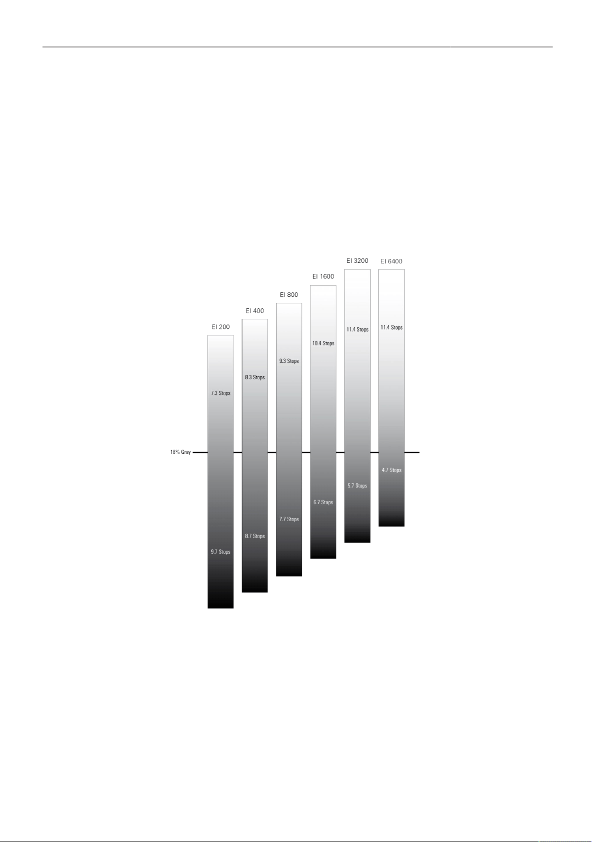
Main Parameters 39
9.4 Exposure Index
The exposure index selects which sensor signal becomes mid gray in the LogC4 image and
consequently in the monitor image. Mid gray is encoded as 28% in the LogC4 signal. When the output
is set to Rec. 709 and no look file is loaded that modifies the signal, mid gray becomes 40% in the
video signal.
The LogC4 signal is exposure normalized. That means, when one closes (opens) the aperture and
increases (decreases) the exposure index by an equivalent amount, mid gray stays at the same value.
Neither varying the exposure nor the exposure index changes the dynamic range of the sensor. By
exposing the sensor differently, the distribution of the tonal range below and above mid gray changes.
This is shown in the figure below.
The LogC4 encoding maintains a fixed relation between signal values and the relative exposure stops
in the scene. For example, a signal value of 10% represents an exposure of 1.5 stops below mid gray
(which is at a signal level of 28%). A signal value of 40% represents 2 stops above mid gray. These
relations stay constant regardless of the exposure index. Because the number of stops above mid gray
that can be captured increases with decreasing exposure, the maximum of the LogC4 function will
change with exposure index.

Main Parameters 40
Setting the Exposure Index
► Select HOME > EI to set the exposure index.
Following options are available:
160
200
250
320
400
500
640
800
1000
1280
1600
2000
2560
3200
4800
6400
2560 ES
3200 ES
4800 ES
6400 ES
User Buttons EI Increase and EI Decrease support to quickly change the exposure index.
Enhanced Sensitivity
In addition to the regular exposure index from EI 160 to EI 6400, it is possible to choose EI 2560 to EI
6400 with Enhanced Sensitivity (ES) turned on. Enhanced Sensitivity is an in-camera noise reduction
that provides cleaner images in low light. ES is an in-camera process, which means it is baked into
ARRIRAW and ProRes files. There also are some frame rate and shutter limits, which will be shown in
the Info Pane visible in the exposure index screen.
9.5 ND Filter
The ALEXA 35 has a built-in motorized and sealed filter stage for Full Spectrum Neutral Density filters
(FSND) with densities of 0.6, 1.2 and 1.8 (and an optical clear filter). In comparison to IRND filters,
which have an uneven spectral behavior, or to an ordinary ND filter, which opens up at about 675 nm,
the FSND filters offer a true, even light attenuation over the whole spectrum. This prevents artifacts
from infrared wavelengths and the need for additional IR filters.
► Select HOME > ND to set the ND filter.
User Buttons ND Increase and ND Decrease support to quickly change the ND filter.
9.6 White Balance
White Balance (WB) is the color balance of the camera that should be matched to the color temperature
of the light in use. White balance is a red-blue adjustment of the image. To adjust the green-magenta
balance, use the color compensation (CC) adjustment. For example, a fluorescent source will have
peaks in its spectrum that cannot be corrected with red-blue white balance alone. The CC shift can
correct these peaks up to a full green or full magenta gel. One step of CC shift is equal to 035 Kodak
CC values or 1/8 Rosco values.
► Select HOME > WB to set the white balance.
► Select a preset from the list or add a custom white balance.
User Buttons WB Increase and WB Decrease support to quickly change between white bal-
ance presets.
Automatic white balance calculates the white balance based on the camera's live image and overwrites
the active white balance value. The result is stored as the first entry in the WB list.
► Select HOME > WB and press Auto WB.
The monitoring outputs display an overlay indicating the area used for white balance calculation.
► Press the Auto WB button again within one second to execute automatic white balance.
The calculated white balance is set and stored as the first entry in the white balance list.

Main Parameters 41
Info: Under- or overexposed images may cause the automatic white balance to fail. Always trigger
automatic white balance with properly exposed images.
User Button Auto WB supports to quickly execute an auto white balance.
9.7 Timecode
Timecode ensures that each frame of recorded material can be identified with a unique value and
synchronized with the appropriate media, such as audio or the second camera in a multicamera
application. In conjunction with other metadata, such as reel names, all recorded media retains its
unique identity.
Timecode Run Mode
Rec Run timecode is often used on single camera productions that are either MOS or use a dumb slate
to synchronize picture and sound. Rec Run timecode guarantees continuous timecode on all recorded
data. The timecode increments only during recording, by one frame for each image generated by the
sensor. Rec Run timecode also works with over- and undercranking.
Free Run timecode is often used on multi camera productions with sync sound, picture/sound timecode
match and allows for easy syncing in post.
The camera can be set to timecode mode Jam Sync, in which it samples the timecode value once from
the timecode connector and then continues counting based on its own high precision crystal clock. The
timecode source can be disconnected from the camera after jamming in Jam Sync mode. This mode
ensures stable timecode with an offset of less than one frame for each eight hours, after which the
camera has to be re-jammed.
Alternatively, the camera can be set to timecode mode Regen (regenerate). In Regen mode, the
camera uses the timecode value of the external timecode source. This ensures correct timecode for an
infinite duration, but the timecode source must remain connected to the camera. Please note that while
recording, the camera ignores external timecode and uses its internal clock to avoid potential timecode
jumps, which can occur due to connection problems such as a faulty timecode cable for example.
► Select HOME > TC > Options > Run Mode.
Following options are available:
Rec Run Timecode increases during recording only. The timecode value increases with every frame
generated by the sensor while recording.
Free Run Timecode increases with every new frame generated by the sensor, independently from
recording.
Free Run timecode is only possible if the sensor frame rate matches the project rate. If the camera
is over- or undercranking, the timecode frame rate will no longer match the sensor frame rate,
and timecode values would either be duplicated or dropped. To prevent this, the camera will
automatically switch to run mode Rec Run when the sensor frame rate is changed. When you set
the sensor frame rate back to equal the project frame rate, the timecode will recall the previous free
run timecode.
Timecode Mode
► Select HOME > TC > Options > Mode.
You have the following options:

Main Parameters 42
Regen Based on the timecode run mode, the camera determines the timecode
source automatically when set to Regen.
If the Run Mode is set to Free Run, the camera regenerates timecode
from the timecode connector. The timecode source must be connect-
ed to the camera permanently. Upon disconnection or loss of signal, the
camera continues counting on its own, but will indicate the missing sig-
nal. When the signal is reconnected, the camera uses the value of the
external signal again.
If Run Mode is set to Rec Run, the camera regenerates timecode from
the last clip of the recording medium by continuing seamlessly from the
last active value.
Preset The camera uses its internal counter.
Jam Sync The camera samples the timecode from the timecode connector and si-
multaneously tunes its internal timecode clock to match the clock of the
timecode source. During this procedure, the timecode display on the
HOME screen, on the timecode menu screen as well as on the Status
Info is blinking. Jamming has finished when the timecode display stops
flashing, now the timecode source can be disconnected.
Info: Jam-sync is not available when Timecode Run Mode is set to Rec
Run.
Info: Due to the tuning mechanism, jamming the camera might take up
to 30 seconds and a timeout is issued if tuning could not be completed
after 60 seconds.
Setting the Timecode Manually
► Select HOME > TC > Options > Timecode.
to edit the timecode.
Info: Timecode can not be set manually when the timecode mode is set to either Regen or Jam
Sync.
Timecode Count Mode
The Count Mode sets the preference for how timecode is counted when using non-integer project rates
(29.97p, 59.94p).
► Select HOME > TC > Options > Count Mode to set the count mode.
Following options are available:
Non-Dropframe Timecode increases with every frame without compensation, resulting in a 1,001 count for
1,000 frames.
Dropframe Timecode values are dropped with a defined pattern (frame counts 00 and 01 of every
minute, except every 10th minute) to re-adjust for the drift. A semicolon between timecode
seconds and frames indicates an active dropframe timecode.
Timecode Offset
You can apply an offset to LTC input signals to compensate for timecode offsets in external devices.
► Select HOME > TC > Options > TC Offset.
► Adjust the timecode offset in the range of -20 to +20 frames.
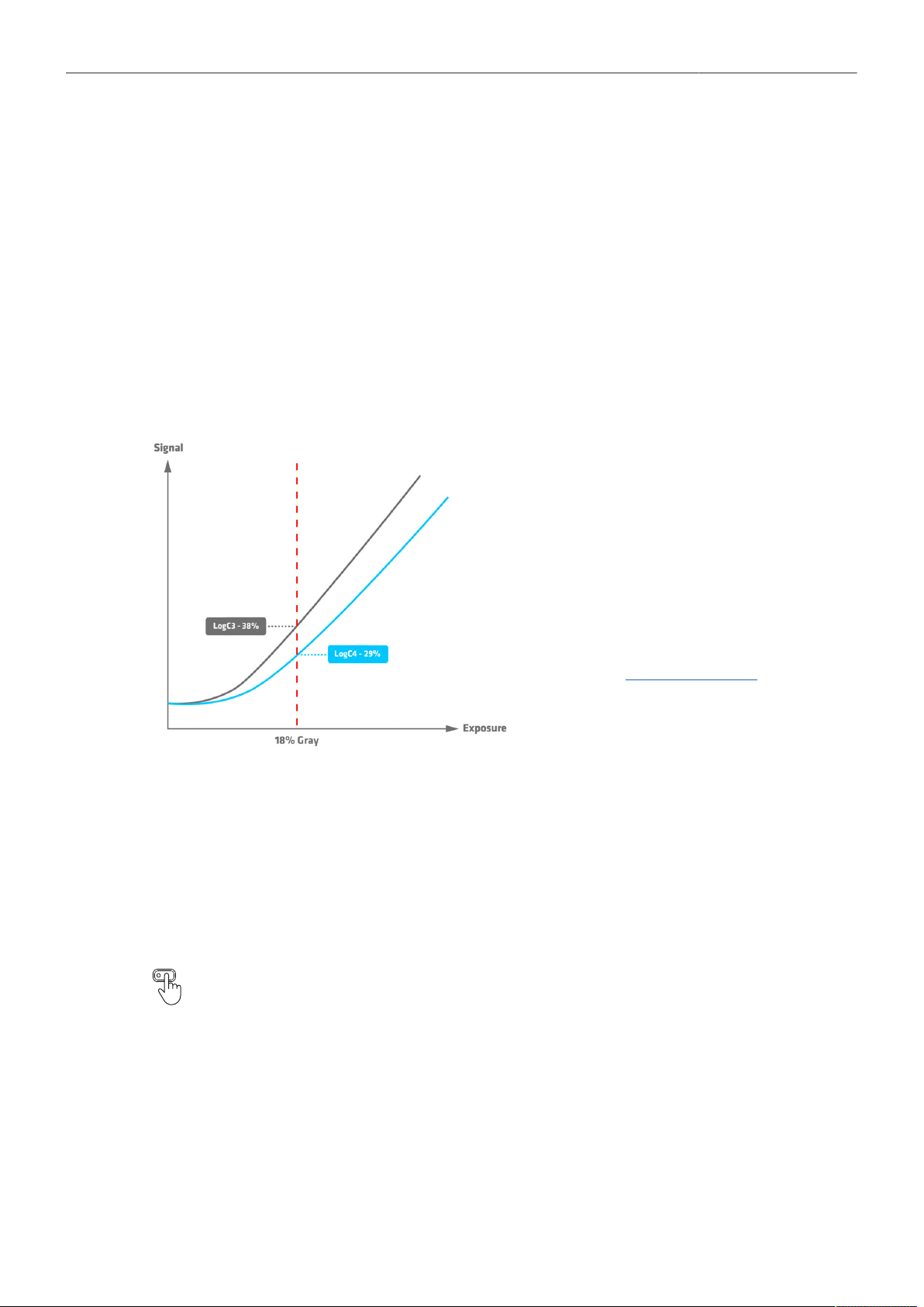
Look Settings 43
10 Look Settings
10.1 Color Processing and Color Space
LogC4
ARRI LogC4 is a direct successor to the prior LogC3 encoding definition in use since 2011 and was
designed to optimize the encoding precision and production usability of the increased dynamic range of
the ALEXA 35's ALEV4 sensor. The LogC curve is a logarithmic encoding of the scene, which means
that the relationship between the exposure measured in stops and the signal is constant over a wide
range. The overall shape of the LogC curve is similar to the exposure curves of film negatives.
However, due to fundamental differences between a sensor and a negative film, the color
characteristics remain different. While the LogC3 curve was different for different exposure indexes
(which made post processing a bit more complicated), the new LogC4 curve has the same shape for all
exposure indexes.
When you look at a LogC4 image, 18% gray
will look darker than it used to in LogC3. Since
the curve extends farther to the right in the
graphic, the point of 18% gray ends up being
lower on the curve.
For further information please see the ARRI
LogC4 Specification, available in the download
section of the ALEXA 35 Website.
VF Processing
► Select MENU > Image > Look > VF Processing to set the processing for the EVF and the Monitor.
Following options are available:
LogC4
Look (SDR)
Look (EVF: HDR, Mon: SDR)
Images are output in LogC4 on EVF and the Monitor.
The active look is applied to EVF and the Monitor in SDR.
The active look is applied to EVF in HDR. The Monitor remains in SDR mode.
User Buttons VF Check LogC4, VF Check HDR and VF Processing support to quickly config-
ure VF Processing.
SDI Processing
► Select MENU > Image > Look > SDI 1 Processing to set the processing for the SDI 1 output.
► Select MENU > Image > Look > SDI 2 Processing to set the processing for the SDI 2 output.
Following options are available:
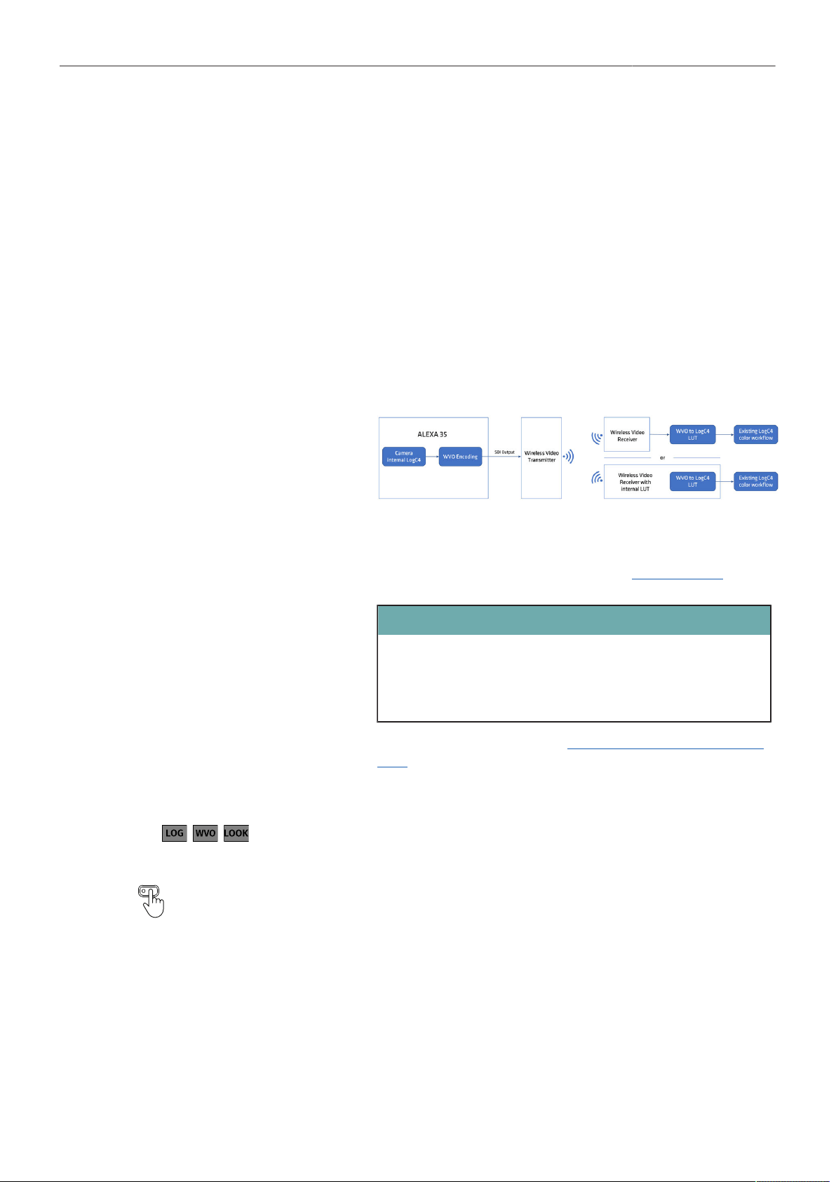
Look Settings 44
LogC4 Images are output in LogC4 on the respective SDI output.
Wireless Video Optimized LogC4 Wireless video transmission systems use compression schemes optimized for
the final image video signal, such as Rec.709. When these transmission sys-
tems are used with a log signal (darker, lower contrast) and stretched to the
limits of their operating range, these compression methods may result in visual
artifacts that can be exacerbated by a log signal.
Wireless Video Optimized (WVO) LogC4 is an intermediate encoding for the
SDI outputs that is designed to improve monitoring image quality when trans-
mitting LogC4 over wireless video transmitters.
At the end of the transmission, the WVO LogC4 signal needs to be decoded
with a corresponding WVO LogC4 decoding LUT before applying any addition-
al color transforms like LUTs or CDLs. This decoding LUT can be loaded direct-
ly into the wireless receiver or become the first node in your on-set color work-
flow:
The result of the decoding LUT is a regular LogC4 signal that can be treated in
exactly the same way as having transmitted LogC4 to begin with.
Download the decode LUT from the ARRI website: WVO decode LUT.
ATTENTION
Please note, that a WVO-encoded image without the decoding LUT is not
compatible with any LogC4 LUT or image analysis tools, such as a false
color display in a monitor. Judging images without the decoding LUT will
mislead and could result in serious exposure issues.
For further information please see the Wireless Video Optimized LogC4 White
Paper.
Look The active look is applied to the respective SDI output.
The applied processing is indicated by the processing icon in the status informa-
tion of the respective output.
User Buttons SDI 1 Check LogC4 and SDI 2 Check LogC4 support to temporarily set the re-
spective output processing to LogC4.
SDI Color Space
► Select MENU > Image > Look > SDI 1 Color Space
► Select MENU > Image > Look > SDI 2 Color Space
Following options are available:
REC 709 (SDR)
REC 2020 (SDR)
REC 2100 / PQ (HDR)
REC 2100 / HLG (HDR)
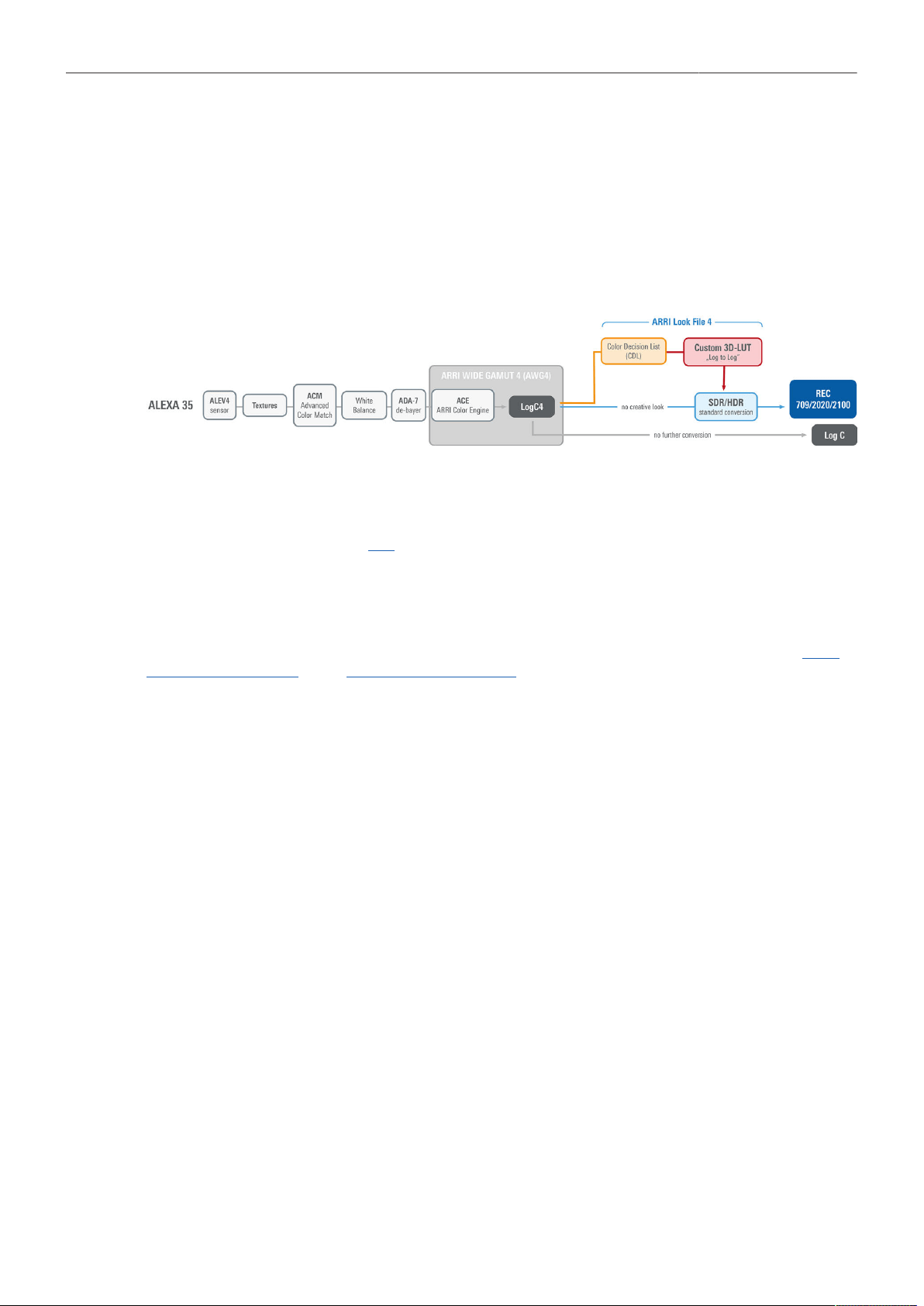
Look Settings 45
10.2 Look File ALF4
The ALEXA 35 uses a new look file (ALF4) which can be created with the ARRI Reference Tool. While
the previous ALF-2 look file contained both the creative intent and the conversion to a display color
space, the new ALF4 look file is a Log-to-Log file that only contains the creative intent.
The conversion to the display color space will be done in a second step in-camera. The advantage on
set is that it is now possible to view SDR and HDR images of the same look. The advantage in grading
is that the colorist can easily combine the on-set look with their own, favorite conversion to a release
color space.
10.3 Setting the Look
► Select MENU > Image > Look > Look.
► Select a look from the list or add a look from an inserted USB medium or the defaults list.
ARRI Look Library
The ALEXA 35 includes the new LogC4 version of the ARRI Look Library. The Look Library provides
a set of 87 predefined looks with a basic repertoire of color responses, similar to film stocks and filters
used with analog cameras. For further information about the ARRI Look Library, please visit the ARRI
Look Library Microsite or the ARRI Look Library FAQs.
► Select MENU > Image > Look > Look > Add > Look Lib.
► Select a look from the list and press IMPORT to add the look to the installed looks list.
► Import further looks from the Look Library or press CANCEL to exit.
Look Duplicate and Rename
► Select MENU > Image > Look > Look.
► Select a look from the list and press DUPLICATE / RENAME.
► Enter a new name and press SET to rename the look, or press DUPLICATE and then SET to
duplicate the look.
Info: The Default look can not be renamed.
Look Export
Look files can be exported to the USB medium to be sent to post production or to be imported on other
cameras.
► Insert the USB medium into the camera.
► Select MENU > Image > Look > Look.
► Select a look from the list and press EXPORT.
The look file is stored in folder ARRI/ALEXA35/LOOKFILES on the USB medium.

Look Settings 46
10.4 Look Intensity
The Look Intensity adjusts the level of look application to the LogC4 image, where 100% translates to
a fully applied look and 0% to a plain LogC4 image. The look intensity is stored as a metadata in the
ALF4 look file. When the look is loaded, the camera reads the metadata and applies the look intensity
accordingly. In this way, the look intensity of a look can be changed as often as desired.
► Select MENU > Image > Look > Look Intensity to set the look intensity of the active look between
10% and 100%.
Info: The active look is stored in the clip metadata. Here, however, the set intensity is “burned” into the
look file with a recalculated LUT.

ARRI Textures 47
11 ARRI Textures
ARRI digital cameras have always had a ‘texture’ setting that is programmed into the way the sensor
captures images and subsequently bakes them (the images) into the ARRIRAW and ProRes outputs.
That texture setting, comprising many carefully balanced parameters, determines the amount of grain in
the image and the character of that grain. It also determines the amount of contrast at different levels of
detail in the image, which defines the perceived sharpness (technically called the MTF curve).
Up until now, ARRI cameras have been pre-programmed with a single, unchangeable texture
setting that is optimized for the widest possible range of shooting scenarios. The ALEXA 35
gives cinematographers the option to go beyond this default texture setting and choose from an
evolving menu of ARRI Textures, each designed for specific applications. This unique feature allows
cinematographers to fundamentally alter the way in which the camera records images.
Behind the three main texture characteristics of grain volume, grain character, and perceived
sharpness, are around 30 image processing settings that occur early in the imaging chain inside the
camera, even before the ARRIRAW image is created. Since many of these steps interact with each
other in complex ways, any user interface providing full access to all settings would be prohibitively
complicated. Instead, we decided to collect sensible combinations of settings into individual ARRI
Texture files. The camera comes with several ARRI Textures pre-installed, which have been designed
in close cooperation with selected cinematographers. ARRI Textures are applied to the image before
the exposure index setting, which controls the camera's sensitivity, and before the ARRI Look File
processing, which controls color. Since ARRI Textures are settings for image processing steps that
occur before the ARRIRAW image is created in the camera, ARRI Textures are always baked into
ARRIRAW and ProRes.
If a texture other than the K445 Default texture is to be used, it is very important for ARRI Textures to
be tested during preproduction, in the highest quality viewing environment possible. An ARRI Texture
that looks right in a DI suite or on a high end display will be very subtle or perhaps even invisible
when viewed in the camera's viewfinder or on the camera's SDI outputs. It is for this reason that we
recommend testing ARRI Textures in preproduction and viewing them on a large (at least 30-inch) high
quality UHD 4K monitor, ideally in HDR. Best practice is to view the images using an HDR 4K grading
display.
If a texture other than the K445 Default texture is to be used, it is very important for ARRI Textures to
be tested during preproduction, in the highest-quality viewing environment possible. An ARRI Texture
that looks right in a DI suite or on a high-end display will be very subtle or perhaps even invisible when
viewed in the camera's viewfinder or on a small regular SDR display connected to the camera's SDI
output. It is for this reason that we recommend testing ARRI Textures in preproduction and viewing
them on a large (at least 30-inch) high-quality UHD 4K monitor, ideally in HDR. Best practice is to view
the images using an HDR 4K grading display.
► Select MENU > Image > Texture > Texture to set the Texture.
Following options are available:
K445 Default The K445 Default texture is designed to work well for all subject matters and settings,
while making the most of the camera’s cinematic strengths. It is forgiving on skin, but al-
so renders images with exceptional clarity and detail, which makes it also a perfect tex-
ture for green screen shots. This is also the texture to use when shooting with ALEXA 35
and previous ARRI digital cameras, as it closely matches those cameras textures. Per-
fect for all EI settings.
P425 Cosmetic A softer texture, very close to the cinematic K445 Default, especially recommended for
rendering skin tones. More forgiving on skin while keeping structures and highlights pro-
nounced. Low to moderate grain. Perfect for all EI settings.
G522 Soft Nostalgic A grainy texture with a subtle vintage feel, designed to render some unsaturated grain
and a softer character. Little softer vintage Texture than G733 Nostalgic. Perfect for all EI
settings.
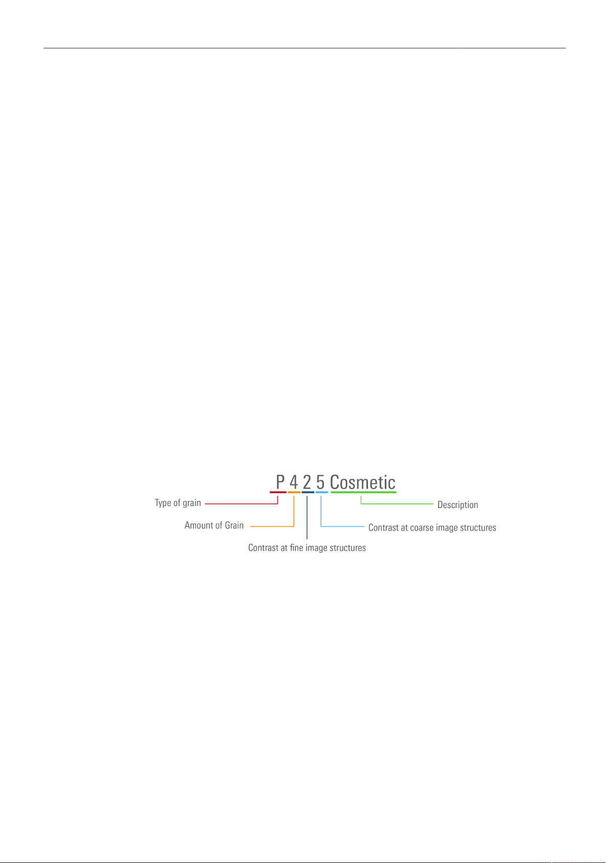
ARRI Textures 48
G733 Nostalgic A grainy texture with a vintage feel, designed to render a lot of grain and a soft charac-
ter. The unsaturated grain type was created based on direct feedback from cinematogra-
phers. Perfect for all EI settings.
F567 Clarity A texture designed to work for any kind of footage, with increased sharpness and detail
compared to the K445 Default texture. The Clarity textures are a perfect choice for land-
scape shots. Works best for low to mid EI settings.
F578 High Clarity A texture designed to work for any kind of footage, with even more detail compared to
the K445 Default texture. The Clarity textures are a perfect choice for landscape shots.
Works best for low to mid EI settings.
L345 Shadow A texture based on the K445 Default texture, with lower noise and grain optimized for im-
ages with a lot of dark content. The visible grain emulates the look of grain in the toe of
color negative film and is more pleasing in darker scenes. Works best for mid to high EI
settings.
H457 Deep Shadow A texture designed for the darkest shots. This texture has low noise, and the remaining
grain is less saturated. It has higher clarity and even more shadow detail retention than
the L345 Shadow texture. Works best for mid to high EI settings.
The applied Texture is indicated by the texture icon in the status information of EVF and SDI 1/2.
Naming Scheme
ARRI Texture names consist of two parts: a technical summary of the texture and a more memorable
word or words that describe the texture. While ARRI Textures represent about 30 image processing
settings, we have distilled those to four important attributes for the technical summary, so you can
quickly tell what to expect.
Type of grain The type of grain can vary in quite complex ways, e.g. more or less
color, fine/coarse etc. The grain of the default Texture K445 Default
complies with a letter in the middle of the alphabet. The bigger the
variations in color, size etc. are of this default grain, the further away is
the letter of another ARRI texture. The closer the letters are in the al-
phabet, the more similar is the impression regarding the type of grain.
Amount of grain A number indicating the amount of grain. The higher the number, the
more grain there is (0 to 9).
Contrast at fine image
structures
This number indicates the amount of contrast for fine image structures
(high spatial frequencies). The higher the number, the higher the con-
trast (0 to 9).
Contrast at coarse image
structures
This number indicates the amount of contrast for coarse image struc-
tures (low spatial frequencies). The higher the number, the higher the
contrast (0 to 9).
Description A descriptive name of the texture.
Recording 49
12 Recording
12.1 Recording Medium
CAUTION
Hot Surfaces on Recording Media
During extended operation, high data rates and/or operation at high ambient temperatures,
the recording media in the camera can get hot to the touch and can cause pain or even
burns if held for too long directly after removal.
Do not handle the recording media for longer than three seconds and remove it quickly but
carefully.
Consider to wear protective gloves when removing the recording media or allow it to cool down
beforehand.
Do not put any labels or adhesive tape on the recording media (especially the side facing the
camera body). The recording media must have full contact to the thermal surface inside the
camera to ensure proper heat conduction.
ADVICE
Recording Media Damage due to improper Handling
Damage to the Recording Media or Loss of Data.
Always insert the recording media as described in this document.
Keep the media door closed to prevent dirt and moisture from entering the camera.
Do not put any labels or adhesive tape on the recording media. The metal surface is used for
cooling. A hot medium can have reduced performance. The plastic surface can easily be broken
off when a label is removed.
Never remove a drive while recording - this may damage the recorded clip.
If the recording process is interrupted by power loss or drive removal, transfer all the data from
the drive and format it before using it again.
While we do everything we can to assure reliable functioning of different recording media such
as Codex Compact Drives, and while the mean time before failure (mtbf) for drives is excellent, a
failure that results in loss of data may occur at any time. Therefore, you are obliged to implement
and maintain at any time adequate and necessary data security measures and back up drive
content as soon as possible. ARRI assumes or accepts no liability or responsibility for data loss
or data corruption, or any other damages, loss or harm due to malfunction of recording drives.
ADVICE
A maximum of 400 clips can be recorded on a drive. When the maximum of 400 clips is reached, the
recording media will be declared as full and further recording onto the media is not possible.
Codex Compact Drives
The Codex Compact Drive is designed to support the demands of creative professionals working with
the ALEXA Mini LF and the ALEXA 35. It offers robust mechanical protection, efficient cooling and a
reliable connector for the integrated, high speed flash memory.
Compact Drives are currently available with 1 TB (960 GB usable) and 2 TB (1920 GB usable)
capacity. The 2 TB drive offers about double speed for all ARRIRAW formats on ALEXA 35. There is no
advantage other than capacity for the Mini LF. At 24 fps ARRIRAW 4.6K 3:2 Open Gate, the recording
time is a little over 25/50 min. At 24 fps Apple ProRes 4444 4K 16:9, the recording time is a little over
90/180 min.

Recording 50
The camera records its data to the ARRI UDF file system which is accessible for operating systems
without the need for special software. Depending on performance vs budget requirements, you can
choose between a USB-C Reader or a Thunderbolt 3 Dock. Mac users who own a SXR Capture Drive
Dock can get a Compact Drive Adapter, which combines high performance with lower pricing.
Recorded material can be accessed directly with the USB-C Codex Compact Drive Reader, the
Compact Drive Dock or an SXR Capture Drive Dock when it is equipped with a Compact Drive Adapter.
Compact Drives are specified for a temperature range from 0 °C to 70 °C (32 °F to 158 °F). When
inserting the drive with a temperature below 0 °C, the camera will go into an alert state and prevent
access to the drive until such time that the media reaches its minimum operational temperature. Once
the media is within specified temperature range, the camera will complete loading the media and
resume regular operation.
Inserting the Codex Compact Drive
► To access the media slot, slide the media door release downwards so that the spring loaded media
door jumps open.
► With the contact pins first and the Codex label side facing out (away from the camera body), gently
insert the drive into the slot until it locks.
► Gently close the media door. Do not force the door closed if the drive is not fully inserted. Do not
force the drive into the slot in wrong orientation - the contacts could be damaged.
Removing the Codex Compact Drive
Compact Drives do not have to be unmounted prior to removal, they can be removed whenever the
drive LED shows solid green.
► Slide the media door release downwards so that the spring loaded media door jumps open.
► Grab the drive with your thumb and index finger and gently pull it out the media slot.
Erasing the Recording Medium
ADVICE
When erasing the recording medium, all data is completely erased and cannot be recovered
afterwards. Make sure that all data has been copied from the medium before erasing.
Do not disconnect the camera from the power supply or turn it off while erasing.
Do not remove the recording medium while erasing.
Before using a Codex Compact Drive with the camera, it must be erased in the camera to create the
required file system. Codex Capture drives are initialized with the UDF file system, which is read only
for computers, and it is named ARRI_UDF until the first clip is recorded. Once a clip has been recorded,
the name changes to the camera index letter and current reel number.
► Select MENU > Media > Erase Media.
► Press ERASE to start erasing the drive, or press CANCEL to cancel.
or
► Select Side Display > Settings > Erase Media.
► Press YES to start erasing the medium, press NO to cancel.

Recording 51
Compact Drive LED States
LED State Media State
Solid Green Drive is in standby, ready to record and safe to remove.
Solid Red Read/write access during Playback or Recording. Do not remove the drive.
Info: As recording is stopped, it takes a few seconds to finalize the recorded clip. During this time, the drive
should not be removed.
Blue flashing Drive is being loaded or unloaded.
Red flashing Drive error, see MENU > Alerts for details.
Off Drive cannot be accessed. Please try reinserting the drive. If the problem persists, check the drive state with
Codex Device Manager.
Media Info
► Select MENU > Info > Media Info for additional information on the inserted medium.
12.2 Recording Codec
MXF (Material eXchange Format)
Both ARRIRAW and Apple ProRes files are recorded in an MXF (Material eXchange Format) container.
An MXF container file can “wrap” different types of video and audio material along with associated
metadata. The internal structure of these files is defined by the Operational Patterns (OP). Our cameras
create MXF files with OP1a structure, which packages picture, sound and metadata into a single file.
This structure is ideal for both camera acquisition and archiving, since audio, video and metadata is
always kept together and virtually no data gets lost if recording is unexpectedly interrupted. OP1a also
is a streaming format, which means that even incomplete files can be repaired and accessed up to the
last recorded frame.
ARRIRAW
ARRIRAW data delivers unencrypted, uncompressed and uncompromised image quality. It offers
the highest achievable resolution, the camera's natural color response and exposure latitude as
uncompressed and unprocessed sensor data. ARRIRAW images have only one channel. A color
reconstruction algorithm calculates the missing components of each pixel based on the type and
position of the array of colored filters (Bayer pattern) on the camera sensor.
ARRIRAW de-bayering is available through the ARRI Imaging SDK only, which is implemented in the
ARRI Reference Tool (ART) and most of the major post production tools for dailies processing and
mastering.
The camera will automatically calculate a CRC32C checksum for the image data inside each
ARRIRAW frame. This checksum is recorded as part of the image header and can be used by software
like the ARRI Reference Tool, to verify that the ARRIRAW image content has not changed during any
copy step. Note that this checksum does not validate the entire file, only the image data. Note that
during the download from the Compact Drive to a computer or afterwards it is possible to reduce the
size of ARRIRAW files by up to 40% using Codex High Density Encoding (HDE) technology with the
ARRIRAW HDE Transcoder app.
Apple ProRes
Recording in Apple ProRes is a cost efficient alternative to shooting ARRIRAW, as it requires less
storage space and no further processing in post.
Info: Apple ProRes is a variable bit rate (VBR) codec. Depending on the content of your images the
remaining recording time on the recording media can be shorter or longer than indicated by the camera.

Recording 52
► Select Menu > Recording > Recording Codec to set the desired recording codec.
Following options are available:
Apple ProRes 422 HQ 12-bit LogC4
YCbCr
Use for high quality TV production. Suitable for creative color correction.
Apple ProRes 4444 12-bit LogC4
YCbCr
Use for high quality TV and cinema production. Very suitable for creative col-
or correction and visual effects work such as pulling mattes.
Apple ProRes 4444 XQ 12-bit LogC4
YCbCr
The ideal choice for productions that are shooting for premium image quality,
are looking for extreme color grading and want to preserve the superior tonal
range of ARRI's Log C signal.
ARRIRAW 13 bit log Use for cinema production, visual effects and high quality TV. It is the best
format for creative color correction, visual effects work and archiving.
Info: Changing between ARRIRAW and Apple ProRes may require a camera reboot.
12.3 Sensor Mode & Recording Resolution
The sensor mode determines the size of the area on the sensor that is read out. This affects the
maximum possible frame rate, the maximum data rate, and which lenses can be used. The sensor
mode naming is composed of the number of horizontal photo sites in “K” (a thousand) and the aspect
ratio used on the sensor.
The recording resolution is the resolution of the file that is being recorded in camera. Most of the time
the number of photo sites read from the sensor and the number of pixels recorded are identical, in
some other cases, as for instance in 4K 16:9 - 2K, the number of photo sites read out from the sensor is
larger than the number of pixels recorded into the file.
► Select Menu > Recording > Sensor Mode to select the desired Sensor Mode.
► Select Menu > Recording > Recording Resolution to select the associated Recording Resolution.
Info: Changing between Sensor Modes may require a camera reboot.
Info: The Recording Resolution is set automatically if a Sensor Mode offers only one associated
Recording Resolution.
4.6K 3:2 Open Gate
4.6K 3:2 Open Gate provides maximum image quality, resolution, and flexibility in post for many
spherical and anamorphic lenses in an image area slightly larger than traditional Super 35 film
specifications.
Active Image Area (Photo sites)
4608 x 3164
Active Image Area (Dimensions)
28.0 x 19.2 mm / 1.102 x 0.756“
Image Circle Ø
33.9 mm / 1.337“
Recording Resolutions
4.6K (4608 x 3164)
4.6K (4608 x 3164)
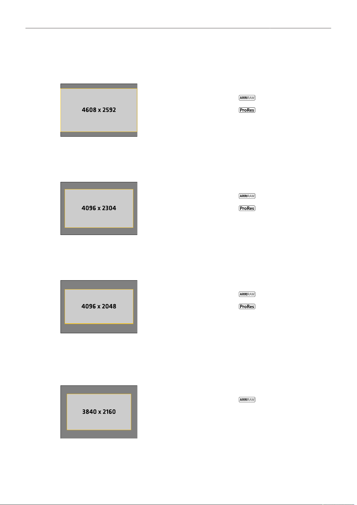
Recording 53
4.6K 16:9
Full sensor width recording in a 16:9 format that suits many spherical Super 35 and all large format
lenses, with room for flexibility in post. Lower data rate than Open Gate.
Active Image Area (Photo sites)
4608 x 2592
Active Image Area (Dimensions)
28.0 x 15.7 mm / 1.102 x 0.618“
Image Circle Ø
32.1 mm / 1.264“
Recording Resolutions
4.6K (4608 x 2592)
4K (4096 x 2304)
4K 16:9
4K 16:9 mimics the traditional spherical Super 35 film format for maximum lens compatibility. Multiple
in-camera downsampling options provide lower data rates.
Active Image Area (Photo sites)
4096 x 2304
Active Image Area (Dimensions)
24.9 x 14.0 mm / 0.980 x 0.551“
Image Circle Ø
28.6 mm / 1.125“
Recording Resolutions
4K (4096 x 2304)
4K (4096 x 2304)
UHD (3840 x 2160)
2K (2048 x 1152)
HD (1920 x 1080)
4K 2:1
4K 2:1 was designed for shooting with all spherical Super 35 and large format lenses for a target
deliverable of 2:1, fulfilling 4K mandates.
Active Image Area (Photo sites)
4096 x 2048
Active Image Area (Dimensions)
24.9 x 12.4 mm / 0.980 x 0.490“
Image Circle Ø
27.8 mm / 1.095“
Recording Resolutions
4K (4096 x 2048)
4K (4096 x 2048)
3.8K 16:9
For projects using spherical lenses for a 16:9 UHD deliverable. Smaller sensor area than sensor mode
‘4.6K 16:9’ ensures that most S35 format lenses cover. Lower data rate and higher fps than sensor
modes ‘4.6K 3:2 Open Gate’ and ‘4.6K 16:9’.
Active Image Area (Photo sites)
3840 x 2160
Active Image Area (Dimensions)
23.3 x 13.1 mm / 0,918“ x 0.516”
Image Circle Ø
26.8 mm / 1.054“
Recording Resolutions
UHD (3840 x 2160)
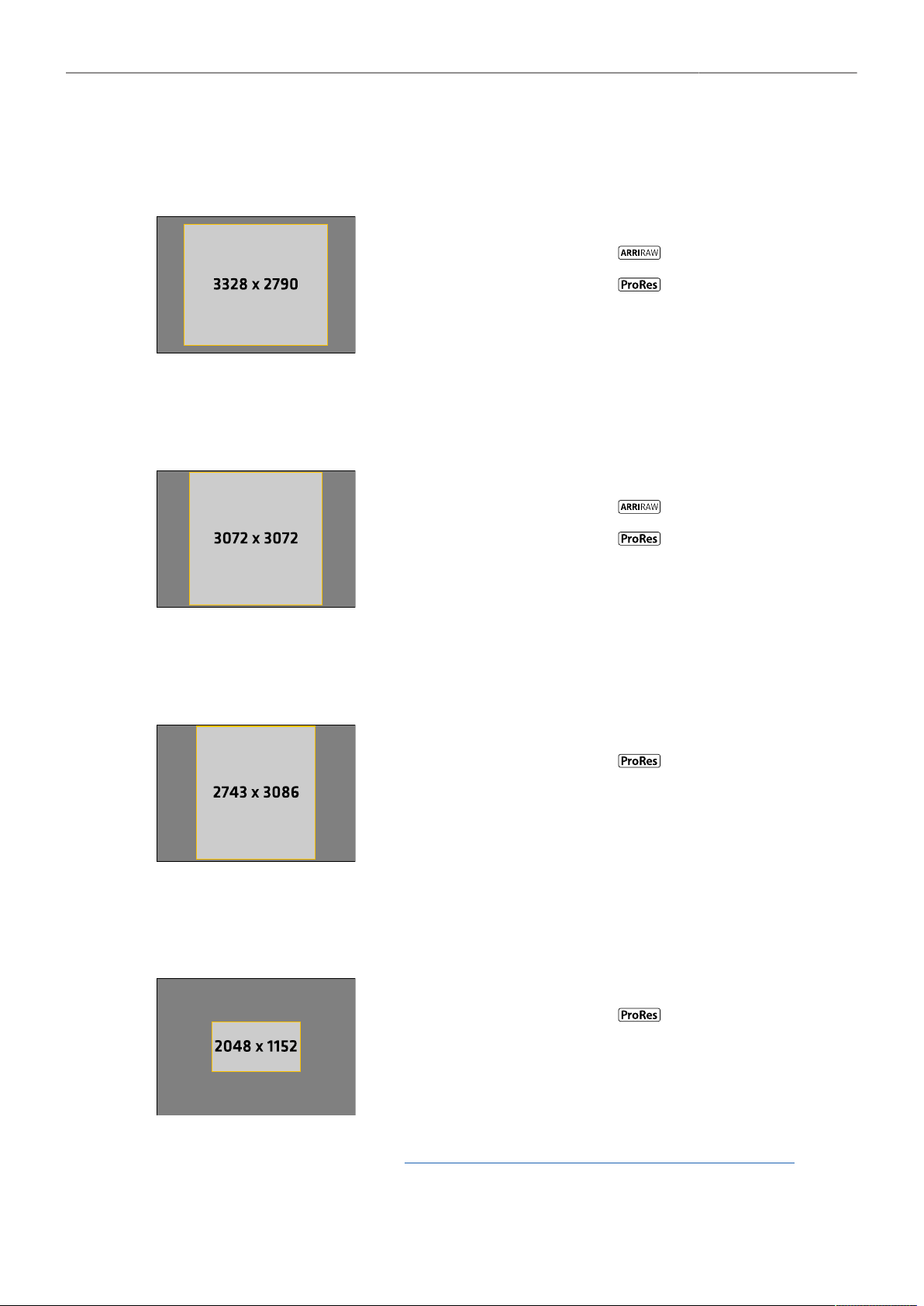
Recording 54
3.3K 6:5
For projects using 2x anamorphic Super 35 lenses for a target deliverable of 2.39:1. Negates necessity
of cropping 4:3 footage and fulfills 4K mandates.
Active Image Area (Photo sites)
3328 x 2790
Active Image Area (Dimensions)
20.2 x 16.9 mm / 0.796 x 0.693“
Image Circle Ø
26.4 mm / 1.039“
Recording Resolutions
3.3K (3328 x 2790)
3.3K (3328 x 2790)
4K 2.39:1 Ana. 2x
(4096 x 1716)
3K 1:1
3K 1:1 was designed for shooting with 2x anamorphic lenses for a target deliverable of 2:1, fulfilling 4K
mandates.
Active Image Area (Photo sites)
3072 x 3072
Active Image Area (Dimensions)
18.7 x 18.7 mm / 0.737 x 0.737“
Image Circle Ø
26.4 mm / 1.041“
Recording Resolutions
3K (3072 x 3072)
3K (3072 x 3072)
3.8K 2:1 Ana. 2x
(3840 x 1920)
2.7K 8:9
For projects shooting with 2x anamorphic lenses for a target deliverable of 16:9, fulfilling 4K mandates.
Desqueeze applied in-camera.
Active Image Area (Photo sites)
2743 x 3086
Active Image Area (Dimensions)
16.7 x 18.8 mm / 0.656 x 0.738“
Image Circle Ø
25.1 mm / 0.988“
Recording Resolutions
UHD 16:9 Ana. 2x
(3840 x 2160)
2K 16:9 S16
2K 16:9 S16 mimics the traditional Super 16 format for use with Super 16 lenses or as an in-camera
center crop.
Active Image Area (Photo sites)
2048 x 1152
Active Image Area (Dimensions)
12.4 x 7.0 mm / 0.490 x 0.276“
Image Circle Ø
14.2 mm / 0.561“
Recording Resolutions
2K (2048 x 1152)
For additional information please see "Data Rates, Recording Times and Max. FPS", page 115.

Recording 55
12.4 Starting Recording
The camera supports various ways to start and stop recording. Recording can be started and stopped
by
The REC button on the camera body, the MVF-2 and ARRI hand units such as the WCU-4 and Hi-5
The Camera Companion App
The Remote Switch RS-4, connected to the camera's RS connector
Through WiFi / Ethernet, using the Web Remote or applications communicating via CAP (Camera
Access Protocol)
User button Record Start/Stop supports to start and stop recording.
User buttons can be assigned to e.g. the ARRI Master Grips, the Operator Control Unit OCU-1
and the General Purpose I/O Box
Starting recording returns the MVF-2 as well as the side display to their HOME screen and disables
access to sensor fps, timecode, shutter, exposure index, auto white balance, erase media, playback
and most menu settings.
12.5 Prerecording
Prerecording writes images into an internal ring buffer for up to 20 seconds in real time instead of
recording them directly to the recording medium. When regular recording starts, the buffered images
are written to the recorded clip. This allows unpredictable events to be captured without wasting media
capacity. The maximum available duration of Prerecording is determined by the set combination of
sensor frame rate, recording codec and sensor mode, but can also be set by the user within these
limits.
Prerecording can only be started and stopped using a user button assigned with Prerecording.
► Select MENU > User Buttons and assign Prerecording to the desired button.
► Press the user button to start Prerecording.
► Press the user button again to end Prerecording or press the REC button to start regular recording.
Info: When ending Prerecording, the ring buffer is cleared.
Info: While Prerecording is active, timecode, shutter, sensor fps, exposure index, auto white
balance, erase media, playback and most menu settings cannot be accessed.
Setting the Prerecording Duration
► Select MENU > Recording > Prerecording max. Duration and set the maximum duration used for
Prerecording in a range from 1 to 20 seconds.
The available Prerecording duration depends on the set Codec, Sensor Mode and Recording
Resolution:
Sensor Mode Recording Resolution Codec Prerec Duration @ 24fps
ARRIRAW 2.8 s
4.6K 3:2
Open Gate
4.6K (4608 x 3164)
Apple ProRes 422 HQ
Apple ProRes 4444
Apple ProRes 4444 XQ
8.5 s
5.6 s
3.6 s

Recording 56
Sensor Mode Recording Resolution Codec Prerec Duration @ 24fps
4.6K (4608 x 2592) ARRIRAW 3.5 s
4.6K 16:9
4K (4096 x 2304)
Apple 422 HQ
Apple 4444
Apple 4444 XQ
12.7 s
8.8 s
5.8 s
ARRIRAW 4.6 s
4K (4096 x 2304)
Apple 422 HQ
Apple 4444
Apple 4444 XQ
12.7 s
8.8 s
5.8 s
UHD (3840 x 2160)
Apple 422 HQ
Apple 4444
Apple 4444 XQ
14.2 s
9.9 s
6.6 s
2K (2048 x 1152)
Apple 422 HQ
Apple 4444
Apple 4444 XQ
20.0 s
4K 16:9
HD (1920 x 1080)
Apple 422 HQ
Apple 4444
Apple 4444 XQ
20.0 s
ARRIRAW 5.2 s
4K 2:1 4K (4096 x 2048)
Apple 422 HQ
Apple 4444
Apple 4444 XQ
14.0 s
9.8 s
6.5 s
3.8K 16:9 UHD (3840 x 2160) ARRIRAW 5.3 s
ARRIRAW 4.7 s
3.3K (3328 x 2790)
Apple 422 HQ
Apple 4444
Apple 4444 XQ
12.9 s
8.9 s
5.9 s3.3K 6:5
4K 2.39:1 Ana 2x
Apple 422 HQ
Apple 4444
Apple 4444 XQ
16.3 s
11.5 s
7.8 s
ARRIRAW 4.6 s
3K (3072 x 3072)
Apple 422 HQ
Apple 4444
Apple 4444 XQ
12.7 s
8.8 s
5.8 s3K 1:1
3.8K 2:1 Ana 2x
Apple 422 HQ
Apple 4444
Apple 4444 XQ
15.6 s
11.0 s
7.5 s

Recording 57
Sensor Mode Recording Resolution Codec Prerec Duration @ 24fps
2.7K 8:9 UHD 16:9 Ana 2x
Apple 422 HQ
Apple 4444
Apple 4444 XQ
14.2 s
9.9 s
6.6 s
2K 16:9 S16 2K (2048 x 1152)
Apple 422 HQ
Apple 4444
Apple 4444 XQ
20.0 s

Recording 58
12.6 Clip Naming Scheme
Camera Index The camera index consists of two characters, A-Z + _. User assignable, it
should match the camera unit. For example, the camera index A_ can be
assigned to the A camera, and B_ to the B camera etc.
Reel Counter 4 characters, 0001-9999. Automatically increments for each blank recording
medium. The user can change the counter for the next reel. This should on-
ly be done under special circumstances, such as after changing the camera
body in the middle of a shoot.
Clip Counter One prefix, fixed to C, to separate the reel counter from the clip counter. 3
characters, 001-400. Automatically increments each time a clip is recorded.
Date Current system date (YYMMDD) as set in MENU > System > System Time
+ Date, separated from the other naming components by an underscore.
Time Current system time (HHMMSS) as set in MENU > System > System Time
+ Date, separated from the other naming components by underscore.
Codec Identifier One character, identifies the clip codec (a = ARRIRAW, p = Apple ProRes).
Camera ID The camera serial number encoded in 4 letters Base 36 (0-9, A-Z). 12RJ
translates into decimal serial number 50239.
File Extension All clips are written as MXF files.
For more information on the Camera Index and the Next Reel Count please see "Project Settings",
page 36.
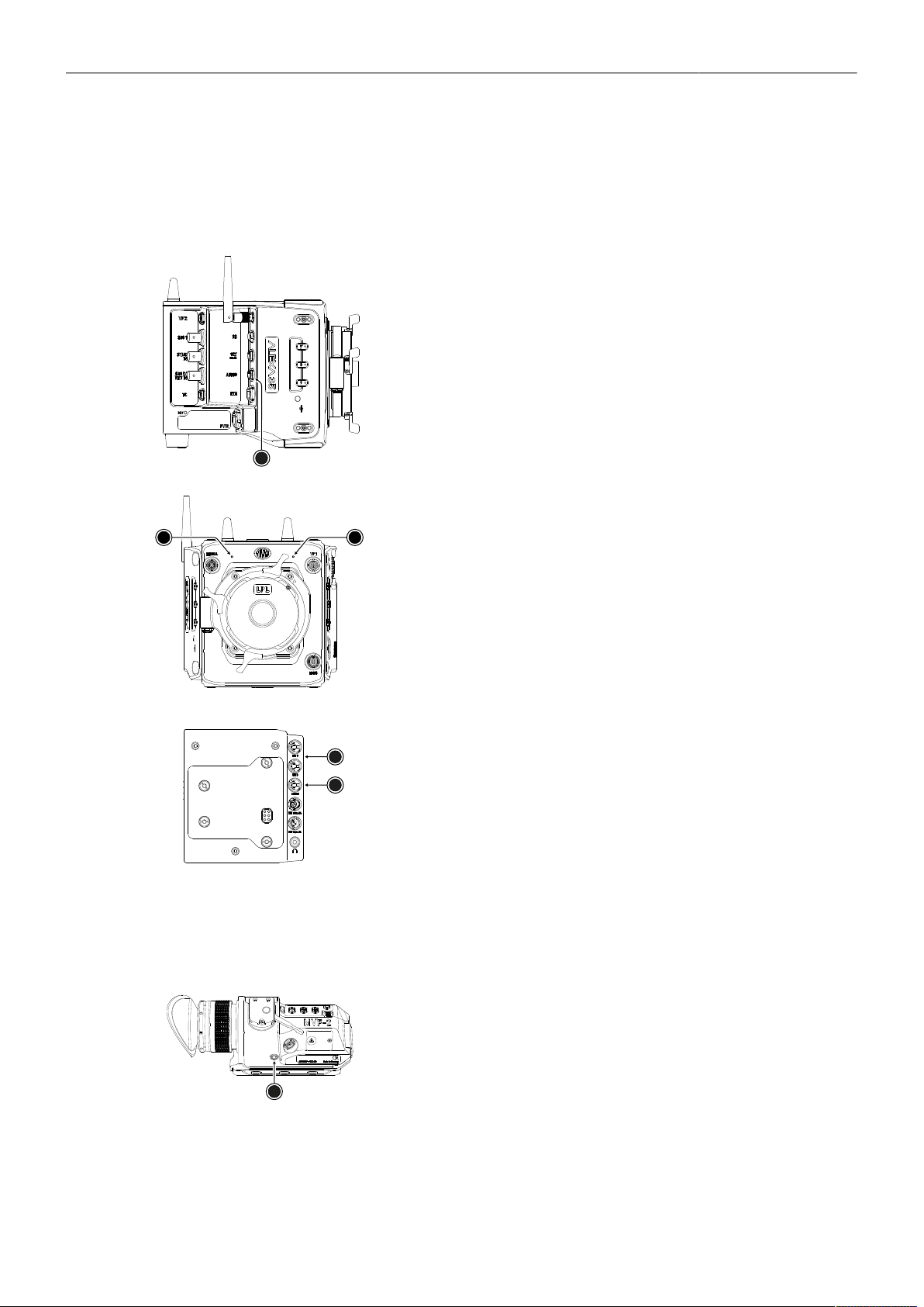
Recording 59
12.7 Audio Recording
The camera supports to record up to 4 channels of linear PCM audio (24 bit, 48 kHz).
Audio Inputs
1
The AUDIO connector (1) is located on the right side of the
camera. It is a two channel +24 dBu line level audio input with
additional 12 V power output to supply microphone preampli-
fiers. This is the same 6-pin connector used on the ALEXA
Mini LF. Use the ALEXA Mini LF Audio connector with cable
(K2.0023988) to connect audio sources.
2
3
The dual gain internal microphones (2 = Internal Mic R, 3 = In-
ternal Mic L, seen from operator point of view) are located at the
camera front and can be used to record a reference track, some-
times called a “scratch track”. Some software tools can synchro-
nize the master sound with the image by using the reference
track. The gain of the internal microphones is fixed, with the left
microphone (3) having a gain of +18 dB and the right microphone
(2) a gain of 0 dB, to cover a wide audio level range.
1
2
The additionally available Audio Extension Module AEM-1 sup-
ports the use of either two balanced Mic/Line inputs (1) with
switchable +48 V phantom power, or one AES3 input (2). It is
docked directly to the rear interface of the camera. For more in-
formation please refer to the user manual of the module.
Audio Outputs
Active audio channels are embedded with a 1 to 1 channel mapping in the SDI stream and also output
via the headphone output of the MVF-2.
1
The headphones out (1) on the MVF-2 is a 3.5 mm TRS connec-
tor (headphone jack) which outputs all four audio channels with
a maximum power of 2.5 dBm. The camera's headphone routing
allows configuring which channels are output on the connector.

Recording 60
Activation of Audio Recording
► Select MENU > Recording > Audio Recording > Audio Recording to enable/disable audio recording.
Enabled audio recording is indicated through the audio meters displayed on the HOME screen as
well as in the Status Info. The meters show the current level of the channel signal in dBFS. Audio
recording is temporarily disabled if the frame rate of the sensor does not match the frame rate of the
project.
Routing of Channels
► Select MENU > Recording > Audio Recording > Channel 1/2/3/4 Source
to set the input source for each channel.
Following options are available:
None No source is assigned to the channel. The channel is not written to the recorded file if subsequent
channels (by channel no.) also do not have a source assigned to them.
Line In L
Line In R
AEM-1 L
AEM-1 R
Internal Mic L
Internal Mic R
The left channel of the camera's AUDIO input is assigned to the channel.
The right channel of the camera's AUDIO input is assigned to the channel.
The left channel from the Audio Extension Module AEM-1 is assigned to the channel.
The right channel from the Audio Extension Module AEM-1 is assigned to the channel.
The left internal microphone is assigned to the channel. This microphone uses a fixed gain of +18dB.
The right internal microphone is assigned to the channel. This microphone uses a fixed gain of 0dB.
An icon on the HOME screen and in the Status Info indicates active internal microphones.
The icon is crossed out when the internal microphones are muted.
Setting the Gain
► Select MENU > Recording > Audio Recording > Channel 1/2/3/4 Control
to set the gain control for each channel which has either Line In L or Line In R assigned as source.
Following options are available:
Manual Gain Allows the user to manually adjust the gain of the input signal on the channel to reach a desired level.
Manual Gain +
Limiter
A limiter prevents the signal from clipping if the input signal level combined with the set gain results in
signal levels exceeding -6 dBFS.
Auto Gain Matches a 0 dBu input signal to -6 dBFS. This setting leaves enough headroom for recording and
avoids audio clipping. Audio levels can not be adjusted by the user.
► Select MENU > Recording > Audio Recording > Ch 1/2/3/4 Gain
to adjust the gain in steps of 1.0 dB for each channel which has either Line In L or Line In R
assigned as source.
Info: Gain adjustment is not available for channels to which the internal microphones or the
Audio Extension Module AEM-1 are assigned as source. The internal microphones use a fixed,
nonadjustable gain, the gain of the signals applied to the AEM-1 must be set on the AEM-1 itself.
Headphones Routing and Headphones Volume
► Select MENU > Recording > Audio Recording > VF Headphone Routing > Channel 1/2/3/4
to configure the routing of audio channels to the headphones.
Following options are available:

Recording 61
Off
L
L + R
R
The audio channel is not output on the headphones.
The audio channel is output on headphones left.
The audio channel is output on headphones left and right.
The audio channel is output on headphones right.
► Select MENU > Recording > Audio Recording > VF Headphone Volume to adjust the volume of the
headphones connected to the MVF-2.
Reference Tone
A 1 kHz sine reference tone can be output on the SDI outputs and the headphone outputs of MVF-2
and AEM-1. If a recording is started during this time, the test tone is also recorded in all active audio
channels of the clip.
► Select MENU > Recording > Audio Recording > Reference Tone.
Following options are available:
Off -9 dBFS -18 dBFS -20 dBFS
Info: The reference tone can only be activated when audio recording is enabled.
User Buttons Audio Ch1 Increase, Audio Ch1 Decrease, Audio Ch2 Increase,
Audio Ch2 Decrease support to quickly adjust gain of channels 1 and 2.
User Button Audio Mute int. Mic mutes the internal microphones.
User Button Audio Solo allows each channel to be monitored individually while the other
channels are muted.
12.8 Rec Beeper and Tally
► Select MENU > Recording > Rec Beeper / Tally.
Following options are available:
Rec Start Beeper
Rec Stop Beeper
Media Full Beeper
The camera gives an acoustic indication at start of recording.
The camera gives an acoustic indication at stop of recording.
The camera gives an acoustic indication for stopping recording due to full recording medi-
um. For better distinction, a different sound pattern than the start/stop beeper is used.
Tally MVF-2 Enables the tally light on the MVF-2.
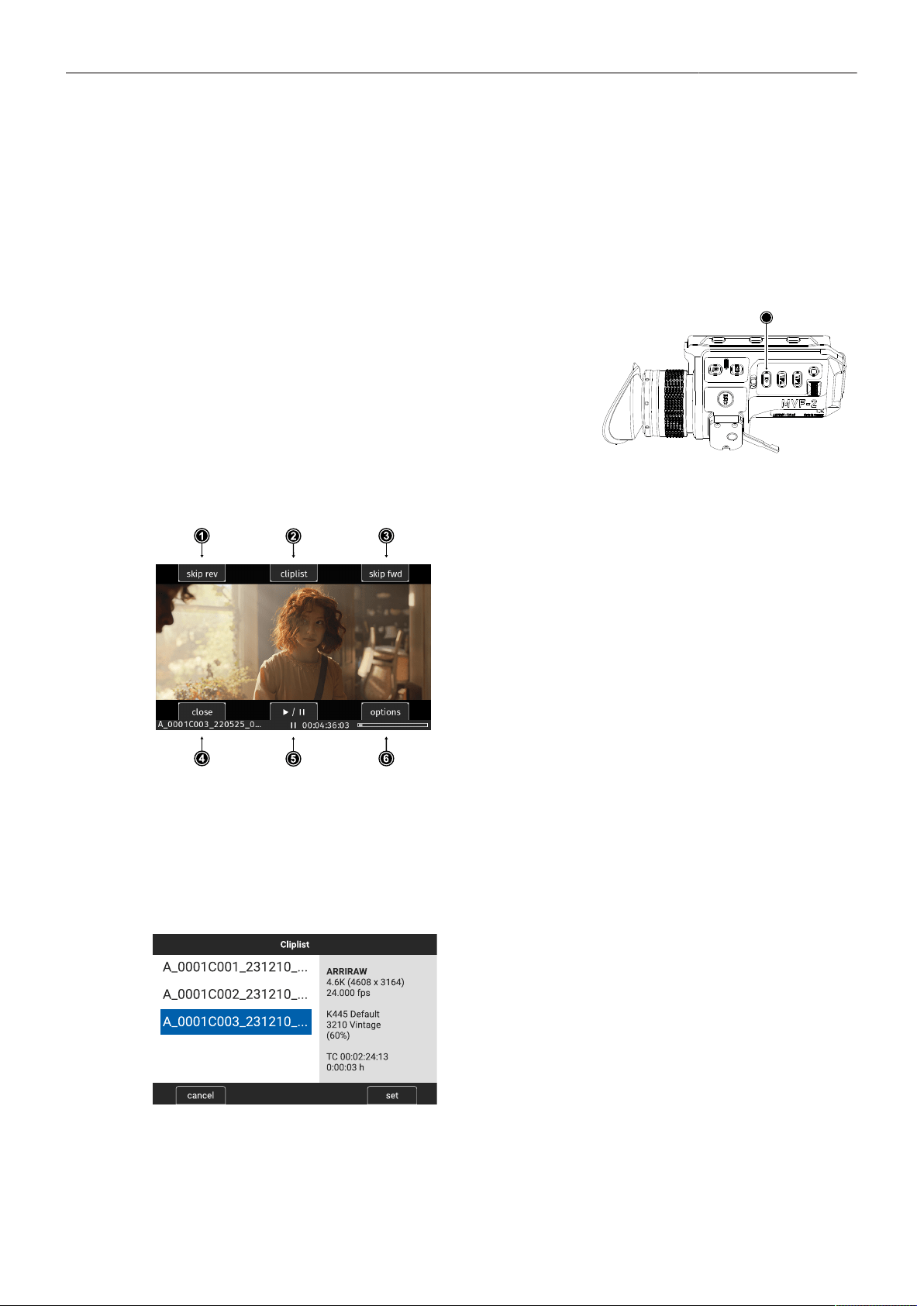
Playback 62
13 Playback
In-camera playback plays back the clips on the recording media at their project frame rate and is output
to EVF, Monitor, SDI 1 and SDI 2. Playback can be controlled from a variety of locations such as the
MVF-2, the camera's side display, the Web Remote, the Camera Companion App or hand units such as
the Hi5.
Playback Control via MVF-2
► Press and hold the PLAY button (1) of the MVF-2 for
one second to start playback.
► Toggle between play and pause by briefly pressing the
PLAY button.
► To exit playback press and hold the PLAY button for one
second.
1
The playback screen of the MVF-2 offers the following controls:
1
2
Skip reverse
Cliplist
Loads the previous clip from the cliplist.
Select another clip for playback from a list of
all clips on the recording medium.
3
4
5
6
Skip forward
Close
Play/pause
Options
Loads the next clip from the cliplist.
Exits playback.
Toggles between play and pause.
Allows setting the clip end action.
Play/pause can also be toggled by pressing the PLAY button on the MVF-2 or by pressing the jogwheel.
While playback is paused, rotate the jogwheel to scroll through the clip frame by frame. During
playback, you can use the jogwheel to increase or decrease the playback speed by up to 512x forward
or backward.
The cliplist lists all clips contained on the recording medium:
► Start Playback and select CLIPLIST
► Rotate the jogwheel to select a clip:
The first frame of the selected clip is displayed on
all monitoring outputs for preview. The clip's prop-
erties are displayed in the info panel on the right:
Codec, Recording Resolution, Record FPS, Tex-
ture, Look and Look Intensity, start TC and clip du-
ration.
Look and Look Intensity are displayed in gray if
the look the clip was recorded with does not corre-
spond to the currently set look.
► Press the jogwheel or the SET button to play the
clip, press CANCEL to return to the playback
screen.
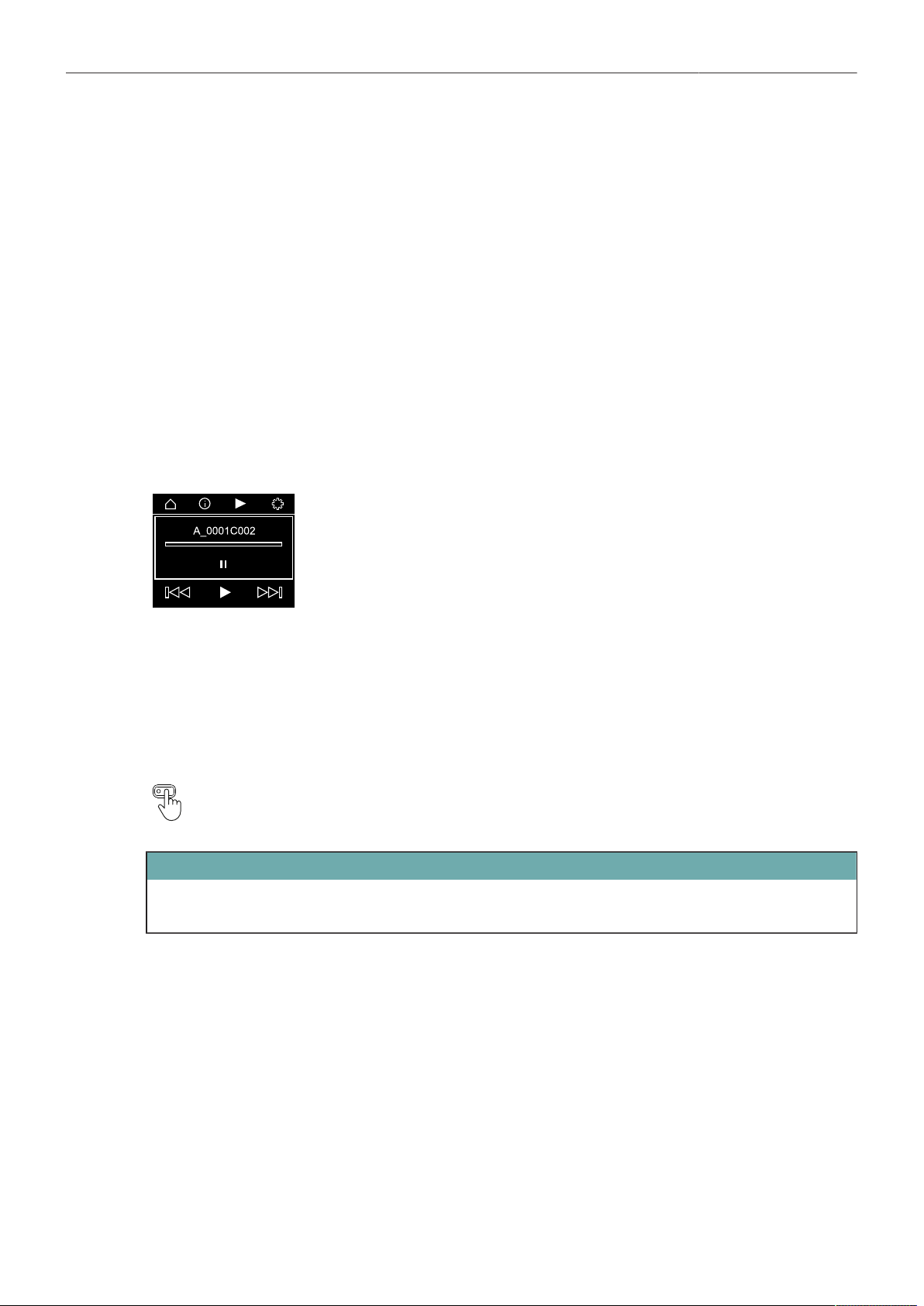
Playback 63
Note: Clips may be grayed out if they can not be played back because their recording resolution is not
compatible with the currently set recording resolution.
The Play End Mode defines the behavior when playback reaches the end of a clip.
► Select PLAY > Options.
Following options are available:
Pause on end
Pause on start
Loop
Play next clip
Exit playback
Playback pauses at the end of the clip.
Playback pauses at the beginning of the clip.
Playback continues from the beginning of the same clip again.
Playback continues with the next clip in the cliplist.
Camera exits playback.
Playback Control via Side Display
► Navigate to the playback page and press the clickwheel to enter play-
back.
► Toggle between play and pause by briefly pressing the clickwheel.
► While playing back, rotate the clickwheel to increase or decrease the
playback speed by up to 512x forward or backward.
► While playback is paused, rotate the clickwheel to switch between the
controls (skip back, play/pause, skip forward, navigation bar).
To exit playback, turn the clickwheel clockwise until the navigation bar is
highlighted. Then press the clickwheel to exit playback mode.
User Button Playback supports to start and exit playback.
User Button Check Last Clip plays the last five seconds of the last recorded clip.
ATTENTION
Playback does not apply the Look file that is stored in the clip metadata. Instead, the currently set
Look file is used during playback.
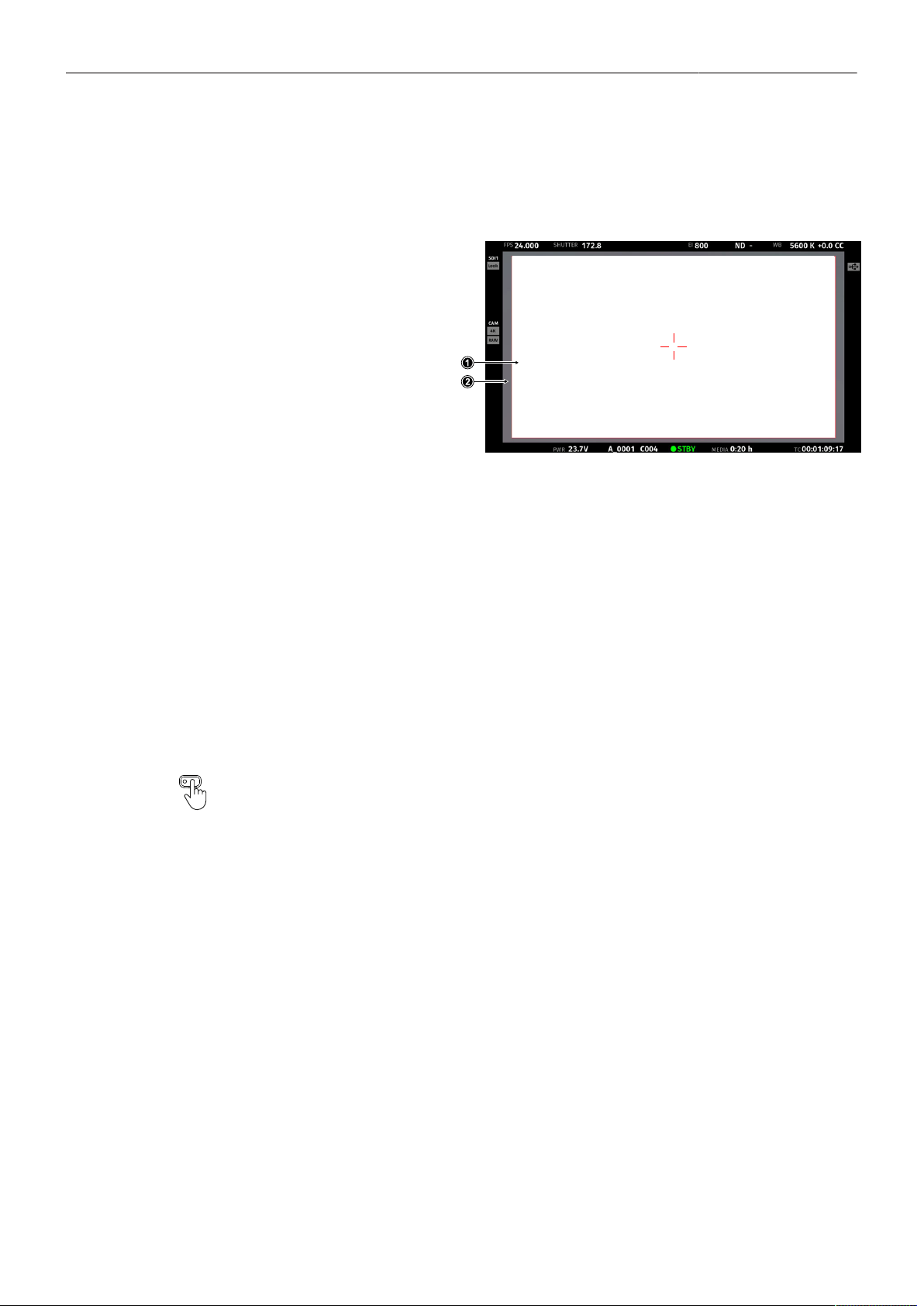
Monitoring 64
14 Monitoring
14.1 Surround View
Surround View displays additional pix-
els outside the captured image area
(1), allowing the operator to see out-
side the captured image and keep un-
wanted objects, such as microphone
booms, out of the shot. The Surround
View area (2) is separated from the
captured image area by the Surround
Mask (here: 75% Mask). To view on-
ly the captured image, Surround View
can be switched off.
► Select MENU > Monitoring > VF > Surround View to configure Surround View for the VF outputs
(EVF and Monitor).
► Select MENU > Monitoring > SDI > SDI 1 Processing > Surround View to configure Surround View
for the SDI 1 output.
► Select MENU > Monitoring > SDI > SDI 2 Processing > Surround View to configure Surround View
for the SDI 2 output.
Following options are available:
On
Off
Off + Colored Line
The captured image area is displayed with Surround View.
The captured image area is displayed without Surround View.
The captured image area is displayed without Surround View, outlined by a colored line
(same color as frame lines).
User Buttons VF Surround View, SDI 1 Surround View and SDI 2 Surround View support
to quickly set the surround view of the respective output.
Info: Surround View is not available for sensor modes 4.6K 3:2 Open Gate and 4.6K 16:9 as there
are no more extra photo sites on the sensor.
Surround Mask
The Surround Mask helps to visually separate the Surround View area from the captured image area.
► Select MENU > Monitoring > VF > EVF Surround Mask to configure Surround Mask for the EVF.
► Select MENU > Monitoring > VF > Monitor Surround Mask to configure Surround Mask for the
Monitor.
► Select MENU > Monitoring > SDI > SDI 1 Processing > Surround Mask to configure Surround Mask
for the SDI 1 output.
► Select MENU > Monitoring > SDI > SDI 2 Processing > Surround Mask to configure Surround Mask
for the SDI 2 output.
Following options are available:
Black Line
Colored Line
Surround View area is separated from the captured image by a black line.
Surround View area is separated from the captured image by a colored line (same color as
frame lines).
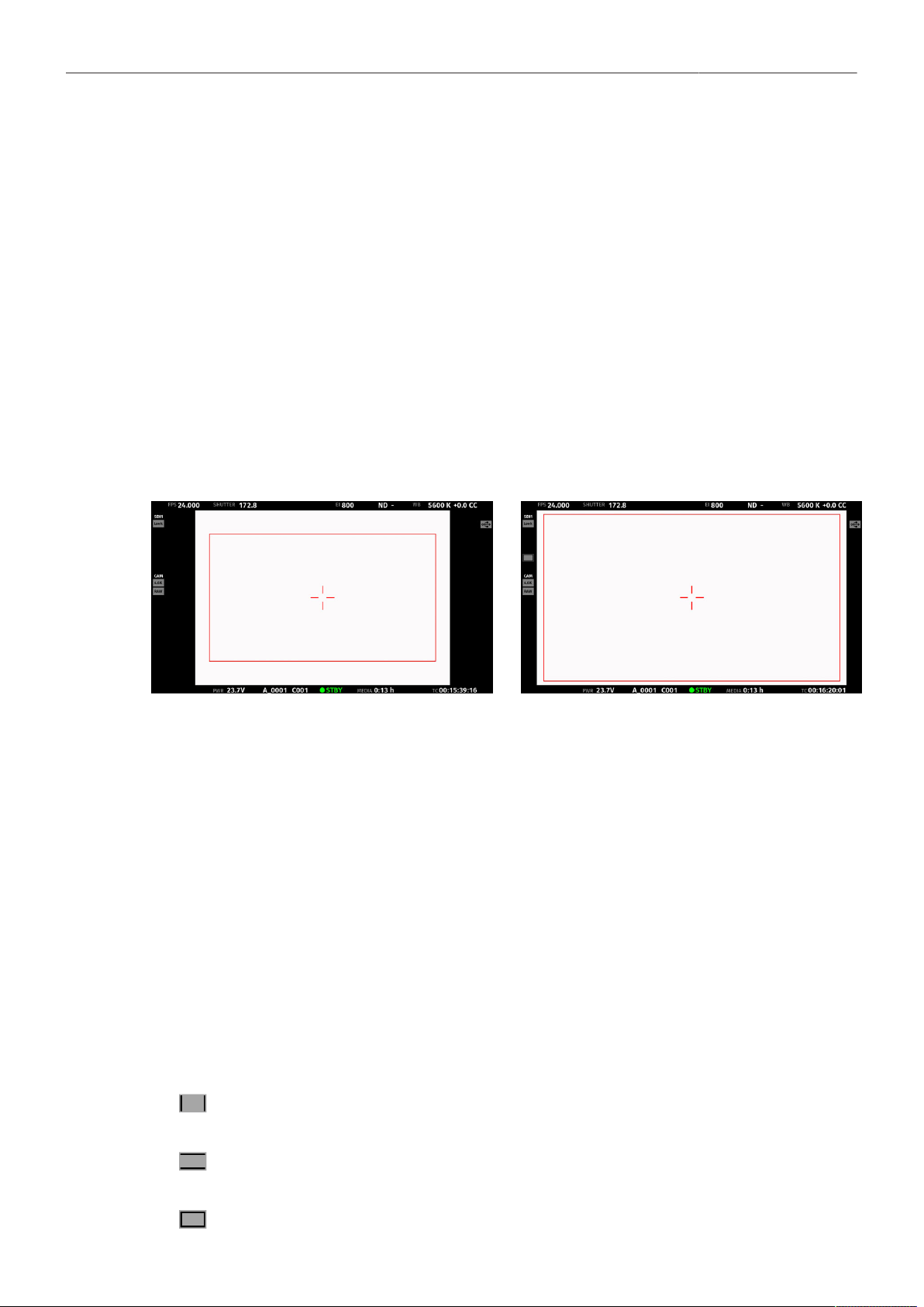
Monitoring 65
25% Mask
50% Mask
75% Mask
100% Mask
Surround View area is separated from the captured image by a mask with 25% opacity.
Surround View area is separated from the captured image by a mask with 50% opacity.
Surround View area is separated from the captured image by a mask with 75% opacity.
Surround View area is separated from the captured image by a mask with 100% opacity.
Info: Monitor Surround Mask does not support 25% Mask and 75% Mask.
Info: When setting the frame lines outside shading for a monitoring output, the Surround Mask of
the corresponding output is automatically adjusted.
14.2 Magnification
When shooting with frame lines or aspect ratios that only use a cropped area of a sensor mode the
actual image content defined by the frame line might not be displayed large enough. The magnification
setting gives the user access to a variable scaling of the monitoring outputs and sets a persistent image
magnification, so the area defined by the frame line can be displayed as large as desired. Magnification
can be adjusted in steps of 1% from 100% to 200% for the VF and the SDI outputs, individually or
globally.
Two screen grabs from an ALEXA 35 in sensor mode 4.6K 3:2 Open Gate with a custom 16:9 4K frame line (red rectangle) ap-
plied. The left screen shot shows the SDI 1 output without magnification applied. The right screen grab shows the SDI 1 output
with magnification applied to enlarge the image (in this example set to 130%).
► Select MENU > Monitoring > Master Magnification to set the magnification level for the VF outputs
and the SDI outputs simultaneously.
When individual outputs have been set to different magnification values, the Master Magnification
menu entry shows “-”. Changing the master magnification will force the magnification of all outputs
to the new value.
► Select MENU > Monitoring > VF > Magnification to set the magnification level for the EVF and the
Monitor.
► Select MENU > Monitoring > SDI > SDI 1 Processing > Magnification to set the magnification level
for the SDI 1 output.
► Select MENU > Monitoring > SDI > SDI 2 Processing > Magnification to set the magnification level
for the SDI 2 output.
The magnification icon on the left side of the Status Info indicates where the recorded area exceeds
the displayed image:
Indication that the recorded image content horizontally (left and right) extends beyond what
is visible on the output.
Indication that the recorded image content vertically (above and below) extends beyond
what is visible on the output.
Indication that the recorded image content horizontally and vertically extends beyond what
is visible on the output.

Monitoring 66
Info:
Magnification can only be applied on the SDI output(s) with SDI Image set to Processed.
Magnification is not available when using 2K or HD Recording Resolutions.
Magnification is reset to 100% when Sensor Mode or Recording Resolution is changed.
Magnification range is limited when using UHD SDI formats (6G and 12G).
14.3 Frame Lines
To aid in framing, the camera offers to display frame lines overlaid over the live image. Frame lines can
be considered electronic versions of ground glass markings in film cameras. You can configure which
frame line the camera should show and how it should be displayed (color and opacity). You can also
configure up to two user rectangles which allow you to mark a rectangular area on the image, e.g. for
marking an area that you need to keep clear during shooting for later VFX insertion. Custom frame lines
can be created using the online Frame Line & Lens Illumination Tool. A standard set of frame lines for
different aspect ratios is provided in the camera, the availability depends on the selected sensor mode.
Setting the Frame Line
► Select MENU > Monitoring > Frame Lines > Frame Line.
► Select a frame line from the list or add a custom frame line from an inserted USB medium or the
defaults list.
Info: Frame lines can be only loaded if their aspect ratio matches the aspect ratio of the set sensor
mode.
Setting the Center Mark
As already common for ground glasses for film cameras, the camera offers to display a center mark on
each monitoring output.
► Select MENU > Monitoring > VF > EVF Overlays > Center Mark to configure the center mark for the
EVF.
► Select MENU > Monitoring > VF > Monitor Overlays > Center Mark to configure the center mark for
the Monitor.
► Select MENU > Monitoring > SDI > SDI 1 Processing > Overlays to configure the center mark for
the SDI 1 output.
► Select MENU > Monitoring > SDI > SDI 2 Processing > Overlays to configure the center mark for
the SDI 2 output.
Following options are available:
Off
Dot
Dot Small
Cross
Cross Small
Center mark is switched off.
Center mark is displayed as a dot.
Center mark is displayed as a small dot.
Center mark is displayed as a cross.
Center mark is displayed as a small cross.
Application of Frame Lines and Center Mark on Monitoring Outputs
For each monitoring output the camera offers to enable/disable display of frame lines and center mark.
► Select MENU > Monitoring > VF > EVF Overlays > Frame Lines to toggle display of frame lines and
center mark on the EVF.
► Select MENU > Monitoring > VF > Monitor Overlays > Frame Lines to toggle display of frame lines
and center mark on the Monitor.
► Select MENU > Monitoring > SDI > SDI 1 Processing > Overlays > Frame Lines to toggle display of
frame lines and center mark on the SDI 1 output.

Monitoring 67
► Select MENU > Monitoring > SDI > SDI 2 Processing > Overlays > Frame Lines to toggle display of
frame lines and center mark on the SDI 2 output.
User Buttons VF Frame Lines, SDI 1 Frame Lines, SDI 2 Frame Lines support to quickly
enable/disable display of frame lines for the corresponding output.
Frame Line Display
When creating custom frame lines using the ARRI Frame Line & Lens Illumination Tool, you have
the possibility to place up to three different frame lines (A, B, C) in one frame line file. However, the
camera does not always have to display all three frame lines at the same time, but offers the possibility
to configure which frame line(s) are displayed. This allows you to quickly switch between or combine
these frame lines without having to load a new frame line file each time.
► Select MENU > Monitoring > Frame Lines > Frame Line Display
Following options are available:
Frame Line A
Frame Line B
Frame Line C
Toggle to enable/disable display of frame line A of the set frame line file.
Toggle to enable/disable display of frame line B of the set frame line file.
Toggle to enable/disable display of frame line C of the set frame line file.
Frame Line Color
The Frame Line Color setting defines the color of the frame line(s), the Center Mark, the User
Rectangle(s) and the Surround Mask (if Surround Mask is set to Colored Line).
► Select MENU > Monitoring > Frame Lines > Frame Line Color.
Following options are available:
Red Green Blue Cyan Magenta Yellow Black White
Frame Line Opacity
The Frame Line Opacity setting defines the opacity of the frame line(s), the center mark, the user
rectangle(s) and the surround mask (if surround mask is set to Colored Line).
► Select MENU > Monitoring > Frame Lines > Frame Line Opacity
► Set the frame line opacity in a range from 1 (the lowest opacity) to 4 (the highest opacity).
Outside Shading
The Outside Shading setting applies shading to the area between the frame line(s) and the remaining
captured image area and can be set independently for each image output. When changing the Outside
Shading of an output, the output's Surround Mask is adapted accordingly.
► Select MENU > Monitoring > Frame Lines > Outside Shading.
Following options are available:
EVF Outside Shading
Monitor Outside Shading
SDI 1 Outside Shading
SDI 2 Outside Shading
Set the outside shading for the EVF (Off, 25%, 50%, 75%, 100%).
Set the outside shading for the Monitor (Off, 50%, 100%).
Set the outside shading for the SDI 1 output (Off, 25%, 50%, 75%, 100%).
Set the outside shading for the SDI 2 output (Off, 25%, 50%, 75%, 100%).
User Rectangles
To further aid in framing, the camera supports to display two custom user rectangle overlays.
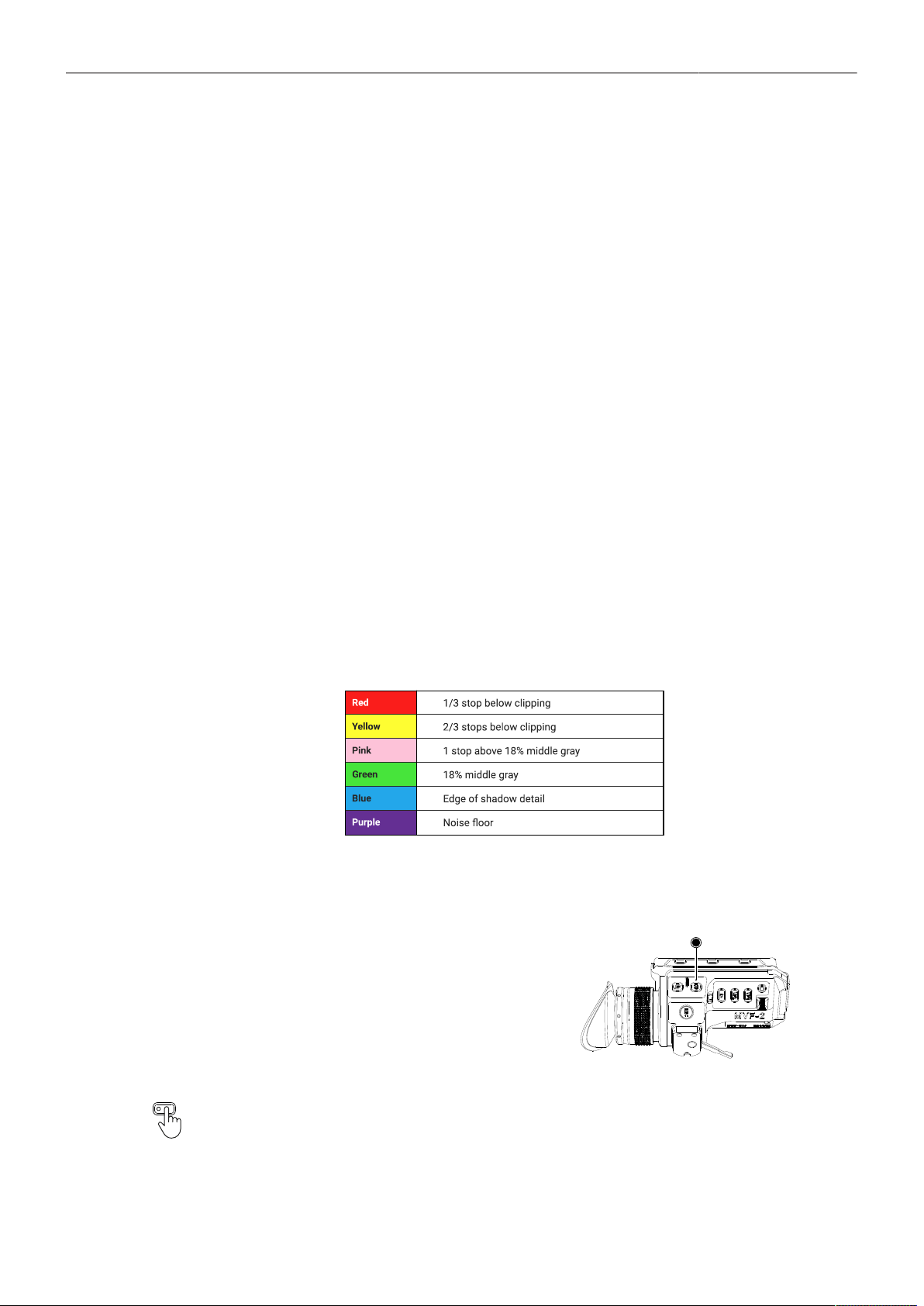
Monitoring 68
You can configure width, height and offset (position from left and top of image area).
► Select MENU > Monitoring > Frame Lines > User Rectangles > User Rectangles.
Following options are available:
Off
Rectangle 1
Rectangle 2
Rectangle 1 + 2
User Rectangles are not displayed.
Only user rectangle 1 is displayed.
Only user rectangle 2 is displayed.
User rectangles 1 + 2 are displayed.
► Select MENU > Monitoring > Frame Lines > User Rectangles > User Rectangle 1 or User
Rectangle 2.
Following options are availabe:
Width
Height
Offset Left
Offset Top
Reset All
Adjusts the user rectangle width in the range of 0-999.
Adjusts the user rectangle height in the range of 0-999.
Adjusts the horizontal user rectangle offset in the range of 0-1000.
Adjusts the vertical user rectangle offset in the range of 0-1000.
Resets all values.
14.4 False Color
False Color is an exposure tool to check for correct exposure. When active, the image is turned into
a gray scale image with important luminance ranges shown in signal colors. Activating False Color
temporarily switches the corresponding output to LogC4 and replaces luminances with the following
colors:
When a gray card is used (or another object in the scene has a similar reflectance level), the exposure
can be set such that the card is in the green zone.
► To activate False Color on both EVF and Monitor,
press the EXP button (1) on the MVF-2. Press the
EXP button again to deactivate False Color.
1
User Buttons VF False Color, SDI 1 False Color and SDI 2 False Color support to quickly en-
able/disable False Color on the corresponding outputs.

Monitoring 69
Additionally, False Color can be activated in the camera menu:
► Select MENU > Monitoring > SDI > SDI 1 Processing > False Color to activate False Color on the
SDI 1 output.
► Select MENU > Monitoring > SDI > SDI 2 Processing > False Color to activate False Color on the
SDI 2 output.
Active False Color is indicated by the exposure tool icon in the Status Info of the respective
output.
14.5 Peaking
Peaking highlights in-focus areas for better focus control.
Info: Peaking is not supported on SDI 2.
Peaking Mode
► Select MENU > Monitoring > Peaking > VF Peaking Mode to set the preferred peaking mode for
EVF and Monitor.
► Select MENU > Monitoring > Peaking > SDI 1 Peaking Mode to set the preferred peaking mode for
SDI 1.
Following options are available:
Color
Aperture
Color peaking overlays in-focus areas with a selected color.
Aperture peaking enhances object edges only.
Peaking Level
► Select MENU > Monitoring > Peaking > VF Peaking Level to set the peaking strength for EVF and
Monitor.
► Select MENU > Monitoring > Peaking > SDI 1 Peaking Level to set the peaking strength for SDI 1.
► Set the peaking level from 1 (the minimum strength) to 20 (the maximum strength).
Offset Shift
The peaking offset shift sets the threshold for Color Peaking to become active, relative to the peaking
level.
► Select MENU > Monitoring > Peaking > VF Peaking Offset Shift to set the peaking offset for EVF
and Monitor.
► Select MENU > Monitoring > Peaking > SDI 1 Peaking Offset Shift to set the peaking offset for SDI
1.
► Set the offset shift from -5 (the minimum) to +5 (the maximum).
Color
Select the color for Color Peaking.
► Select MENU > Monitoring > Peaking > VF Peaking Color to set the color for color peaking on EVF
and Monitor.
► Select MENU > Monitoring > Peaking > SDI 1 Peaking Color to set the color for color peaking on
SDI 1.
Following options are available:
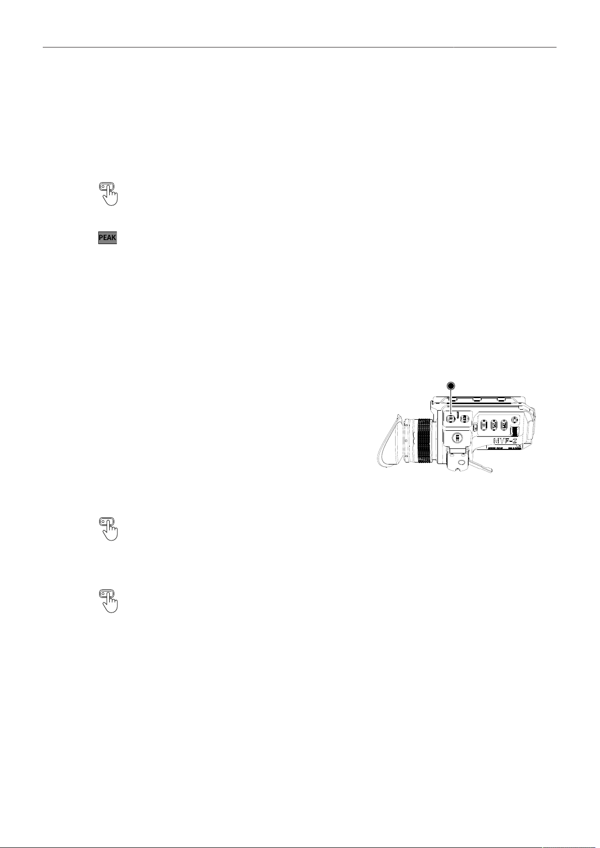
Monitoring 70
Red
Green
Blue
Cyan
Magenta
Yellow
White
Activation of Peaking
User Buttons VF Peaking and SDI 1 Peaking support to quickly enable/disable peaking on the
respective output.
Active peaking is indicated through the peaking icon displayed in the Status Info of the respective output.
14.6 Zoom
The camera supports to zoom into the image e.g. to better judge focus. Zoom is essentially a shortcut
to quickly achieve maximum Magnification. The camera offers six zoom positions: center, top left,
top center, top right, bottom right and bottom left. While Zoom is activated, the zoom position can be
changed by using the jogwheel, the soft buttons on the MVF-2 (if the Monitor is flipped out and set to
display the live image) or through user buttons. Active Zoom is indicated by an orange frame around
the image. Frame lines and anamorphic desqueeze are temporarily deactivated while Zoom is active.
► Press the ZOOM button to activate/deactivate
Zoom on EVF and Monitor.
► To change the Zoom position, rotate either the jog-
wheel or the user wheel.
Info: Changing the zoom position using the jog-
wheel or user wheel is not supported when the
Monitor is set to display the HOME screen or the
camera menu.
1
User Buttons VF Zoom, VF Zoom Position, VF Zoom (Smart) support to quickly enable/disable
and adjust zoom for the viewfinder.
Zoom on SDI
Zoom on the SDI outputs can only be activated through a user button. The camera offers three
SDI Zoom related user button functions:
► Select MENU > User Buttons and assign SDI 1 Zoom or SDI 2 Zoom to the desired button.
The user button activates/deactivates Zoom on the respective SDI output.
► Select MENU > User Buttons and assign SDI 1 Zoom Position or SDI 2 Zoom Position to the
desired button.
While Zoom is activated, the user button changes the Zoom position on the respective output.
► Select MENU > User Buttons and assign SDI 1 Zoom (Smart) or SDI 2 Zoom (Smart) to the desired
button.
The user button activates Zoom on the first button press, further button presses change the zoom
position and a button long press deactivates Zoom.
Info: Zoom is not available when using 2K or HD recording resolutions.

Monitoring 71
Info: SDI Zoom is not available when using UHD SDI formats (6G & 12G).
Info: Zoom always refers to the entire image area of the set sensor mode and does not take into
account any set Magnification.
14.7 SDI Settings
SDI Image
The setting for the SDI image determines whether the SDI image is output as a clean feed or including
status information and status overlays.
► Select MENU > Monitoring > SDI > SDI 1 Image
Following options are available:
Clean Image is output as a clean feed. Neither status overlays, frame lines nor surround view are dis-
played. Magnification is not supported.
Processed Image may include status information and overlays.
► Select MENU > Monitoring > SDI > SDI 2 Image.
Following options are available:
Clean Image is output as a clean feed. Neither status overlays, frame lines nor surround view are dis-
played. Magnification is not supported.
Processed Image may include status information and overlays.
The SDI 2 output is automatically configured by the SDI 1 settings. The following SDI 1 settings
are transferred to the SDI 2 output:
Clone SDI 1
Format
Surround View
Overlays
Status Info
Hide Messages
Color Space
Frame Rate
Surround Mask
Frame Lines (on/off)
Status Components
Outside Shading
3G Level
Image (clean/processed)
Magnification
Center Mark
Overlay Brightness
Processing (LogC4 / WVO
LogC4 / Look)
SDI Format
► Select MENU > Monitoring > SDI > SDI 1 Format to set the format of the SDI 1 output.
► Select MENU > Monitoring > SDI > SDI 2 Format to set the format of the SDI 2 output.
Following options are available:
422 1.5G HD Images are output according to SMPTE 292M.
Available frame rates are 23.976p/psf, 24p/psf, 25p/psf, 29.97p/psf and 30p/psf
p (progressive) transmits images line by line starting at the top left pixel.
psf (progressive segmented frame) splits progressive images into fields (odd lines and even lines) and trans-
mits these (all odd before all even) line by line.
422 3G HD Images are output according to SMPTE ST 424:2012
Available frame rates are 48p, 50p, 59.94p and 60p

Monitoring 72
444 3G HD Images are output according to SMPTE ST 424:2012
Available frame rates are 23.976p, 24p, 25p, 29.97p and 30p
422 6G UHD Images are output according to SMPTE ST 2081-10:2015
Available frame rates are 23.976p, 24p, 25p, 29.97p and 30p
422 12G UHD Images are output according to SMPTE ST 2048-1
Available frame rates are 48p, 50p, 59.94p and 60p
444 12G UHD Images are output according to SMPTE 2082-10:2015
Available frame rates are 23.976p, 24p, 25p, 29.97p and 30p
Info: 48p may not be supported by some SDI devices, as this is not a defined frame rate according
to the SMPTE standard.
Info: 6G / 12G formats are not available when the recording resolution is set to 2K or HD.
SDI Frame Rate
The SDI frame rate determines the number of images that are output per second on the SDI output(s).
It should be set equal to the sensor frame rate. If the frame rate is lower than the sensor frame rate,
frame drops will occur. If it is higher, duplicate images will be output. The available SDI frame rates
depend on the selected SDI format.
► Select MENU > Monitoring > SDI > SDI 1 Frame Rate to set the frame rate of the SDI 1 output.
► Select MENU > Monitoring > SDI > SDI 2 Frame Rate to set the frame rate of the SDI 2 output.
SDI 3G Level
For the 3G SDI formats, you can choose whether to use 3G level A or B. Refer to the instructions of
your connected devices to decide which 3G level to use.
► Select MENU > Monitoring > SDI > SDI 1 3G Level to set the 3G level for the SDI 1 output.
► Select MENU > Monitoring > SDI > SDI 2 3G Level to set the 3G level for the SDI 2 output.
Hide Messages
User messages displayed as overlays on the monitoring outputs are primarily relevant for the camera
team and do not necessarily need to be displayed on the SDI output that other crew members are
viewing. The camera offers the possibility to suppress all user messages on a selected SDI output.
► Select MENU > Monitoring > SDI > SDI 1 Processing > Hide Messages to hide user messages on
the SDI 1 output.
► Select MENU > Monitoring > SDI > SDI 2 Processing > Hide Messages to hide user messages on
the SDI 2 output.
14.8 EVF and Flip-out Monitor Settings
EVF Brightness
The brightness of the EVF is adjustable with values 120, 200 and 300 (Nits).
► Select MENU > Monitoring > VF > Settings > EVF Brightness to set the brightness of the viewfinder
OLED between 120, 200 or 300.
Info: When VF Processing is configured for Look (EVF: HDR, Mon: SDR),, the EVF brightness is
fixed to 500 nits and can't be changed.
EVF Power
► Select MENU > Monitoring > VF > Settings > EVF Power

Monitoring 73
Following Options are available:
Auto EVF display is activated and deactivated automatically, depending on the MVF-2 proximity sensor state.
This is the default setting.
Off Deactivates the EVF display permanently so that it remains switched off even when the proximity sensor
is covered e.g. by a rain cover.
On Use this setting to override the MVF-2 proximity sensor and to constantly enable the EVF display. This
setting should be regarded as an emergency setting to be used, for example, when the proximity sensor
is faulty and no longer activates the EVF display anymore.
ADVICE
Please be aware that when enabled, and used for prolonged periods, this configuration may cause
irreversible burn-ins on the EVF OLED. With the setting enabled, the camera will issue a corre-
sponding warning after each boot-up and sensor mode switch.
EVF Eyepiece Heating
The MVF-2 viewfinder is equipped with a built-in eyepiece heater to prevent fogging of the eyepiece
when shooting in cold environments. The eyepiece heater becomes active when the eyepiece has a
temperature of 15° C / 59° F or below. In really cold environments please use the Heated Eyecup HE-7.
► Select MENU > Monitoring > VF > Settings > EVF Eyepiece Heating to enable/disable EVF
eyepiece heating.
Active eyepiece heating is indicated through an icon displayed on the HOME screen. The
icon is displayed gray if eyepiece heating is inactive.
EVF Image Rotation 180°
When mounting the MVF-2 on the right side of the camera, the EVF image can be rotated by 180° for
correct orientation.
► Select MENU > Monitoring > VF > Settings > EVF Image Rotation 180° to enable/disable the
rotation.
Monitor Brightness
► Select MENU > Monitoring > VF > Settings > Monitor Brightness
to adjust the brightness of the MVF-2 flip-out monitor from 1 (the minimum brightness) to 10 (the
maximum brightness).
Monitor Flip Mode
1. Select MENU > Monitoring > VF > Settings > Monitor Flip Mode
Following options are available:
Auto
Normal
Flipped
Flips the Monitor image automatically depending on the monitor's orientation. This is the default setting.
Ignores the Monitor's orientation sensor and displays the Monitor image in normal orientation.
Ignores the Monitor's orientation sensor and displays the monitor image in flipped orientation (upside
down).
User Button Flip Monitor supports to quickly set the Monitor flip mode.

Monitoring 74
14.9 Return In
The SDI 2 output of the camera can be switched to a Return In input to feed 1.5G or 3G SDI signals
into the camera and display them on the EVF and flip-out monitor and/or the SDI 1 output.
► Select MENU > Monitoring > Return In > Use SDI 2 as Return In to configure the SDI 2 output to
function as an image input.
► Select MENU > Monitoring > Return In > Show Return In on VF to display the return in image on
the EVF and the Monitor.
► Select MENU > Monitoring > Return In > Show Return In on SDI 1 to display the return in image on
the SDI 1 output.
Info: SDI 2 related settings can't be adjusted while SDI 2 is configured to function as return in.
Activation of Return In
Return In can only be switched on and off using a user button assigned with Return In.
► Select MENU > User Buttons and assign Return In to the desired button.
► Press the user button to activate Return In.
14.10 SDI Color Bars
The camera supports to output SMPTE color bars on the SDI outputs. The color bars are a 10-bit signal
according to SMPTE RP 219-2002. Color bars will always bypass the ALF4 look file. These are SDR
color bars, set the SDI color space to either Rec 709 (SDR) or Rec 2020 (SDR) for correct display.
► Select MENU > Monitoring > SDI Color Bars to switch color bars on or off.
Info: Color bars are switched off when recording is started.
User Button SDI Color Bars supports to quickly enable/disable color bars on the SDI outputs.

User Buttons 75
15 User Buttons
The camera is equipped with nine assignable user buttons, 1-6 on the
left and 7-9 on the camera right side. The MVF-2 is equipped with two
additional user buttons, VF 1 and VF 2. Each button can be assigned a
variety of functions.
Once a button is assigned a function, press the button to trigger the
function. The blue LED on the button reflects the functional status.
In addition to the user buttons of the camera and the MVF-2, the camera
supports to assign functions to the user buttons of electronic accessories
such as the hand units HI-5 and WCU-4, ARRI Master Grips, Operator
Control Unit OCU-1 and the GPIO box.
Some user button functions support smart behavior. For these, a short press triggers the func-
tion, while a long press activates the function only temporarily, as long as the user button is
pressed.
► Select MENU > User Buttons >
Button VF 1 or Button VF 2
Camera User Buttons
Hand Unit User Buttons
LBUS Device User Buttons
to assign the MVF-2 user buttons.
to assign the camera user buttons (1-9).
to assign the user buttons of HI-5 and WCU-4 (1-6).
to assign the user buttons of the ARRI Master Grips and the
OCU-1 (1-12).
GPIO User Buttons
Lens RET
to assign the user buttons of the GPIO Box (1-14).
to assign the RET button of an ENG lens servo.
Following user button functions are available:
Off
VF , SDI 1, SDI 2 Status Info
VF , SDI 1, SDI 2 Check LogC4
Disables the user button.
Switching Status Info between Safe, Off and Overlay on the chosen output.
Switching the processing of the chosen output between the currently set value
and LogC4. Supports smart behavior.
VF Check HDR Switching the EVF processing between the currently set value and HDR.
Supports smart behavior.
VF , SDI 1, SDI 2 False Color Switching the False Color exposure tool on and off on the chosen output.
Supports smart behavior.
VF , SDI 1, SDI 2 Frame Lines Switching the frame lines on and off on the chosen output.
Supports smart behavior.
VF , SDI 1 Peaking (smart)
VF Processing
Switching Peaking on and off on the chosen output. Supports smart behavior.
Switching VF Processing between LogC4, Look (SDR) and Look (EVF: HDR,
Mon: SDR).
VF , SDI 1, SDI 2 Surround View Switching Surround View between On, Off and Off + Colored Line on the cho-
sen output.

User Buttons 76
VF , SDI 1, SDI 2 Zoom
VF , SDI 1, SDI 2 Zoom Position
VF , SDI 1, SDI 2 Zoom (smart)
Switching Zoom on and off on the chosen output.
Switching the zoom position.
Press to activate Zoom. Further button presses switch the Zoom position. A
button long press deactivates Zoom.
SDI Color Bars
EI Increase
EI Decrease
FPS Increase
FPS Decrease
FPS Preset
ND Increase
ND Decrease
Shutter Increase
Shutter Decrease
WB Increase
WB Decrease
Audio Ch1 Increase
Audio Ch1 Decrease
Audio Ch2 Increase
Audio Ch2 Decrease
Turns SDI color bars on or off.
Increases the exposure index to the next value in the list.
Decreases the exposure index to the next lower value in the list.
Sets the sensor frame rate to the next higher value in the list.
Sets the sensor frame rate to the next lower value in the list.
Sets the sensor frame rate to a user defined value.
Sets the ND filter to the next higher value in the list.
Sets the ND filter to the next lower value in the list.
Sets the shutter to the next higher value in the list.
Sets the shutter to the next lower value in the list.
Sets the white balance to the next higher value in the list.
Sets the white balance to the next lower value in the list.
Increases gain of audio channel 1 in 1dB steps.
Decreases gain of audio channel 1 in 1dB steps.
Increases gain of audio channel 2 in 1dB steps.
Decreases gain of audio channel 2 in 1dB steps.
(requires channel control set either to Manual or Manual (+L))
Audio Mute int. Mic
Audio Solo
Mutes / unmutes the internal microphones.
Mutes all audio recording channels except one. Toggles through Off, Ch1, Ch2,
Ch3, Ch4, selecting the next channel with every button press. Channels that
are not assigned to an audio input are skipped. When Audio Solo is active, the
selected channel is marked in the audio bars displayed in the status info and
the homescreen. Audio Solo only affects the headphones output (not the em-
bedded audio in the SDI stream).
Auto WB First press displays the auto white balance overlay, press the button again
within one second to execute auto white balance.
Check Last Clip
EF Close Iris
EF Open Iris
Plays the last five seconds of the last recorded clip, then playback is exited.
Closes the iris of an EF lens (only available when EF Mount is attached).
Opens the iris of an EF lens (only available when EF Mount is attached).
Short press closes/opens by 1/x stop (step size depending on lens), long press
closes/opens by 1 stop.
Flip Monitor Switching the flip-out monitor between normal and flipped mode. To return to
automatic flip mode, press and hold button for two seconds.

User Buttons 77
Frame Grab Grabs a LogC4 still frame in .JPG and .DPX format and saves it to the USB
medium. Frame grabs are taken from the SDI image path (including SDI set-
tings such as processing, active look and anamorphic desqueeze) but cropped
to the active image area. Hence, the frame grab resolution depends on the SDI
format and the applied SDI settings.
Active frame grab is indicated though the grab icon displayed on
the HOME screen as well as the Status Info. The icon turns orange
when the frame grab could not be saved.
Mirror Image
Playback
Switching Mirror Image between Off, V, H and V+H.
Press and hold to start playback, then press to toggle play/pause, press and
hold again to exit playback.
Prerecording
Record Start/Stop
Return In
Starting and stopping Prerecording.
Starting and stopping recording.
Switching on and off the return in signal present at the SDI 2 connector.
Supports smart behavior.
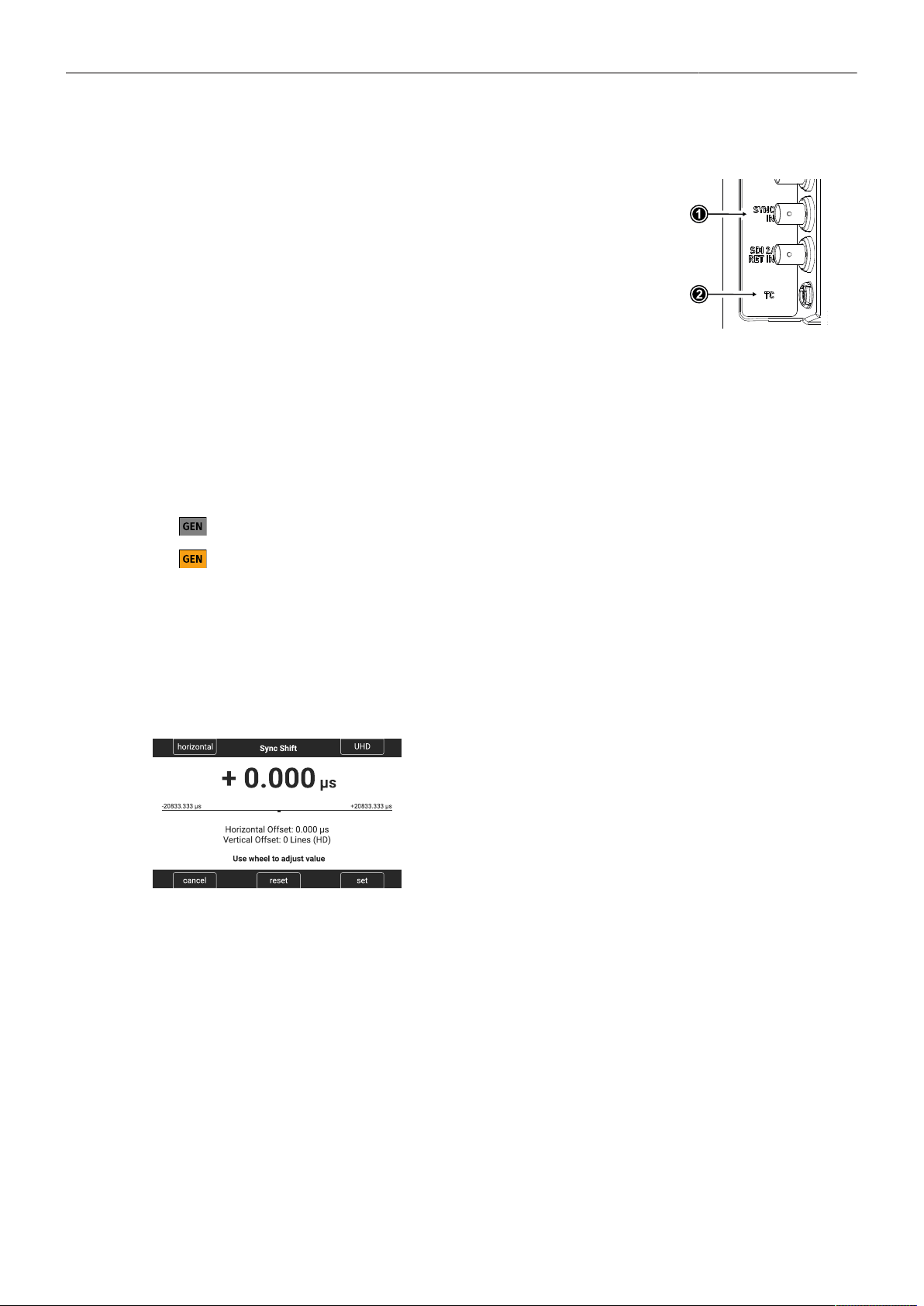
Synchronization 78
16 Synchronization
The camera's sensor and SDI outputs can be synchronized to either
a genlock signal (a tri-level HD signal or an analog black burst sig-
nal) present at the BNC SYNC IN connector (1) or a timecode signal
present at the 5-pin LEMO TC connector (2). The camera's sensor
needs to run at equal or double the frame rate of the reference signal
to establish synchronization.
► Select MENU > System > Sensor > Genlock Sync.
Following options are available:
Off
Sync In
Timecode
Synchronization is not enabled.
The camera will synchronize to a tri-level or black burst signal present at the SYNC IN connector.
The camera will synchronize to timecode present at the TC connector.
Active synchronization is indicated by the Genlock icon on the HOME screen and in the
Status Info. The icon turns orange when the camera cannot synchronize to the reference
signal or when no signal is present. See MENU > Alerts for detailed information.
Info: Simultaneous use of the timecode mode Jam-sync and Genlock Sync is not supported.
Sync Shift
The Sync Shift setting can be used to apply an offset to the reference signal at the input. The minimum
step size is 52 ns and the maximum correction is +/- 20 ms, depending on the sensor frame rate.
► Select MENU > System > Sensor > Sync Shift.
► Use the upper left button to switch between horizontal
(minimum stepsize of 52ns) and vertical (entire lines)
shift.
► Use the upper right button to switch the vertical shift be-
tween HD and UHD lines.
► Use the clickwheel to adjust the shift.

Sensor Settings 79
17 Sensor Settings
17.1 Mirroring the Sensor Image
You can mirror the sensor image in horizontal and vertical directions.
Horizontal mirroring is applied on all monitoring paths and internally recorded material. Vertical
mirroring is only applied to the monitoring outputs; internally recorded material is not vertically flipped,
but the information is written into metadata.
► Select MENU > Image > Mirror Image.
Following options are available:
Off
V
H
V+H
Mirroring is inactive.
The sensor image is vertically mirrored.
The sensor image is horizontally mirrored.
The sensor image is vertically and horizontally mirrored (rotated by 180°).
User Button Mirror Image supports to quickly switch Mirror Image.
17.2 User Pixel Masking
All sensors exhibit a certain number of defect pixels, and ARRI cameras have three mechanisms
to catch and correct them: one is a static pixel correction based on a pixel mask created during
manufacturing. The second is a dynamic pixel correction that continuously evaluates each frame and
masks defect pixels that are not caught by the static pixel mask. In very few cases, we have observed
some pixels that are not corrected by either method; for those cases the third, User Pixel masking, is
available. User pixel masks can be created using the ARRI Reference Tool (ART).
When shooting ARRIRAW, it is not necessary to load the User Pixel Mask into the camera. Instead,
it can be applied to the ARRIRAW files in post production using the ARRI Reference Tool or any third
party software that has implemented the User Pixel Mask feature through the ARRI Image SDK.
The User Pixel Mask will remain intact after a factory reset and after a camera software update. It can
be manually removed or overwritten with a new one at any time.
► Select MENU > System > Sensor > User Pixel Masking.
Install User Pixel Mask Select to install a User Pixel Mask from USB memory stick.
Export User Pixel Mask Select to back up the currently installed User Pixel Mask onto USB
memory stick.
Delete User Pixel Mask Select to uninstall a User Pixel Mask.
Grab Raw Image Stores an ARRIRAW frame grab on the USB memory stick.
User Pixel Mask Generation
► Insert a USB memory stick into camera.
► Select MENU > System > Sensor > User Pixel Masking > Grab Raw Frame to grab an ARRIRAW
frame.
The ARRIRAW frame grab is stored on the USB memory stick in folder ARRI/ALEXA35/SENSOR.
Alternatively, you can record a short ARRIRAW sequence and use that material for marking defect
pixels.
► Import the ARRIRAW frame grab into the ARRI Reference Tool.

Sensor Settings 80
► Use the ARRI Reference Tool to mark defect pixels. The marked pixel coordinates are stored in an
XML file called the User Pixel Mask. Please note that it is advisable to mark the least number of
pixels necessary, as too many marked pixels can be counter productive.
Please refer to the ARRI Reference Tool user manual for further information.
► Save the User Pixel Mask to the USB memory stick in folder ARRI/ALEXA35/SENSOR.
► Insert the USB memory stick into the camera.
► Select MENU > System > Sensor > User Pixel Masking > Install User Pixel Mask to load the mask
into the camera.
► After a restart of the camera, the marked pixels will be masked using information from surrounding
pixels. This masking is applied to the images delivered from the sensor, before any other
processing takes place, and therefore becomes active on all outputs.
► Carefully check the end result by visually inspecting the areas where you have marked pixels; if too
many pixels are marked too close to each other, or if pixels are marked close to other pixels that are
already marked in the static pixel mask, the result could be uncorrectable clusters, which are more
visible than the original defect pixels.
As an added service, it is possible to send the User Pixel Mask to ARRI Service at [email protected]
for verification. We strongly recommend that you take advantage of this free service, as sometimes,
clusters are difficult to spot depending on the background. Please note, however, that in the end, it is
the responsibility of the person creating the User Pixel Mask to verify that no clusters are formed.
ADVICE
Please note, that the User Pixel masking feature is only a temporary solution to mask defect pixels.
Defect pixels should be dealt with by sensor calibration at an ARRI service department.
A User Pixel Mask is a stopgap solution between when the defect is noticed, and when the
camera is recalibrated, to verify the sensor is still functioning within ARRI specifications and to
comprehensively assess and permanently and automatically compensate for defect pixels.

System Settings 81
18 System Settings
18.1 Language Setting
► Select MENU > System > Language to set the system language between English and Chinese
(simplified).
18.2 System Time and Date
► Select MENU > System > System Time + Date to set the system time and date.
18.3 Button and Display Settings
► Select MENU > System > Buttons + Display > Display Style to set the display style between Day or
Night.
► Select MENU > System > Buttons + Display > Button Brightness or
► Select Side Display > Settings > Button Brightness
to set the brightness of camera and MVF-2 buttons from 0 (off) to 4 (the highest brightness).
18.4 Fan Settings
Select to set the fan mode to Low Noise for locations with ambient temperatures up to 30°C (86°F). For
locations with ambient temperatures higher than 30°C (86°F), set to Rec Low.
► Select MENU > System > Fan Mode.
Following options are available:
Rec Low Increases fan speed during standby to cool the camera. Minimizes fan speed/noise during
recording. Ideal in an environment warmer than 30 °C (86 °F).
Low Noise Minimizes fan noise during standby and recording.
Info: With data rates above 100 MB/s (due to fps/codec setting), the fan speed automatical-
ly increases to prevent the camera from overheating.
18.5 Reset of Electronic Horizon
► Select MENU > System > Reset Electronic Horizon.
► Place the camera on a level surface and press RESET.
Info: A message is displayed if either the roll, the tilt or both values exceed the calibration range
and resetting is not possible.

System Settings 82
18.6 Update
ADVICE
Use a fully charged battery or a mains power supply to avoid power loss during updates.
Do not switch off the camera or unplug power during update processes.
Do not disconnect or remove components that are being updated.
18.6.1 Update of Camera Software
The camera software is updated using a USB-C memory stick. The Software Update Package (SUP)
will update the camera along with the MVF-2 and the lens mount – provided they are connected to the
camera. Before updating the camera, create the required folder structure on a USB-C memory stick.
For more information, see "User Storage".
Software Update Package Download
► Download the software update package (SUP) from the Software and Firmware Updates for
Cameras section of our website.
► Double-click on the downloaded file (*.zip) to unpack it:
Update file (*.swu) Update key (*.lic) Release notes
► Carefully read the release notes.
► Copy the update file (*.swu) to folder ARRI/ALEXA35/SUP on the memory stick.
► Copy the update key (*.lic) to folder ARRI/ALEXA35/LICENSES on the memory stick.
Camera Update
► Connect the USB-C memory stick to the camera.
► Select MENU > Setup > Factory Reset to perform a factory reset.
► Select MENU > System > Update > Update Camera.
► Select the required update file and press CONFIRM to start the update.
Wait for the update process to finish. The update procedure takes about ten minutes.
After a successful update and reboot, the camera displays a success message.
18.6.2 Update of Camera Components
The camera supports to update the MVF-2 viewfinder and the lens mount. Updating the MVF-2 and the
lens mount does not require a dedicated update file. The camera will issue a message if the software
version of MVF-2 and/or the lens mount does not match the version required by the currently installed
camera software.
► Select MENU > System > Update.
The Update MVF-2 and Update Lens Mount entries show the software version installed on the
component and the software version required by the currently installed camera software.
► Select Update MVF-2 to update the MVF-2 or
Select Update Lens Mount to update the lens mount.
► Press CONFIRM to start the update.
System Settings 83
18.6.3 Update of LBUS Devices
LBUS devices such as cforce mini motors, cforce Plus motors, ARRI Master Grips, ARRI Operator
Control Unit OCU-1 and ARRI LCUBE can be updated by the camera. The update requires an update
file which can be downloaded from the ARRI website.
► Download the update file for the desired device from the Software Updates ECS section of our
website.
► Copy the update file onto a USB-C memory stick in folder ARRI/ECS/.
Connect the memory stick to the camera.
► Connect the LBUS device to the LBUS connector of the camera or the lens mount.
► Select MENU > System > Update > Update LBUS Devices.
A list with the connected LBUS devices is displayed, showing the software version currently
installed on the device and the software version stored on the memory stick.
► Select the LBUS device you want to update and press UPDATE.
► Press CONFIRM to start the update. Cancel with BACK.
18.6.4 Update of Codex Compact Drive
The camera supports to update Codex Compact Drives. Updating does not require a dedicated update
file. The camera will issue a message if the firmware version of the inserted drive needs to be updated.
ADVICE
All data contained on the drive will be deleted by the update. Make sure that you have
backed up all data before starting the update.
► Select MENU > System > Update.
The Update Media entry shows the software version installed on the inserted Compact Drive, and
the software version required by the currently installed camera software.
► Select Update Media to update the inserted Compact Drive.
► Press CONFIRM to start the update.
Info: After the update, the camera must be rebooted to be able to record and resume normal operation.
However, if additional drives need to be updated, no reboot is required, you can proceed directly with
the update of the next drive.
18.6.5 Update of PDM-1
The camera supports to update the Power Distribution Module PDM-1. Updating does not require a
dedicated update file. The camera will issue a message if the firmware version of the PDM-1 needs to
be updated.
► Select MENU > System > Update.
The Update PDM-1 entry shows the software version installed on the PDM-1, and the software
version required by the currently installed camera software.
► Select Update PDM-1 to update the PDM-1.
► Press CONFIRM to start the update.

User Setups 84
19 User Setups
A user setup is a profile of the current settings on the camera that can be saved on camera and/or to
a USB memory stick. User setups can be given custom names, saved to the USB memory stick and
loaded onto multiple cameras. Rather than resetting the camera to its factory default settings, a user
setup can be used to reset the camera to a user's default settings.
User setups can be used to ensure that cameras on multi camera shoots have matching settings, or to
transfer a show’s setup onto daily cameras, to ensure they carry the same shooting specifications.
Saving a User Setup
You can save the current setup configuration in the camera or to the USB medium.
► Select MENU > Setup > User Setups Installed > Save to save the setup in the camera.
Select MENU > Setup > User Setups on USB > Save to save the setup on the USB medium.
► Use the onscreen keyboard to enter a name for the user setup and press SAVE.
A screen is displayed to select the setup parameter blocks with following options:
General
Format
Scene
Lens
User
Groups the general camera configuration and basic project settings.
Saves set codec, sensor mode and recording resolution.
Saves scene related parameters such as Shutter and Exposure Index.
Saves active lens table setting to quickly change between lens configurations.
Stores all parameters for camera personalization (overlays etc.)
► Select one or more options and press CONFIRM.
Loading a User Setup
► Select MENU > Setup > User Setups Installed to load a setup from the camera.
Select MENU > Setup > User Setups on USB to load a setup from the USB medium.
► Select a user setup from the list and press LOAD.
A pop up window with the parameter blocks of this user setup is displayed.
► Press CONFIRM.
The camera loads the selected user setup and shows a result message. The pop up highlights the
parameters that you should check in case certain parameters could not be loaded.
Factory Reset
You can reset the camera to the ARRI factory default values.
► Select MENU > Setup > Factory Reset.
► Press RESET.
The camera settings are reset to factory defaults.
Info: A factory reset does not delete user setups stored/installed on camera.

User Setups 85
19.1 User Setup Parameter Blocks
The camera allows you to store a full camera configuration by selecting all parameter blocks, or only
parts of the configuration by de-/selecting the desired blocks. The parameter blocks have been chosen
to allow for maximum flexibility while keeping coherent sets of parameters and minimizing the amount
of potential conflicts by loading partial setups.
General
Groups the general camera configuration and basic project settings.
Project Rate
Audio (All Settings)
Timecode (All Settings)
Metadata (All Settings)
Genlock Sync
Sync Shift
Installed Look Files
Installed Texture Files
Installed Frame Line Files
CAP Settings
Mirror Image
Fan Mode
Sensor FPS Presets
Shutter Presets
WB Presets
ECS Radio Power
ECS Radio Channel
Prerec max. Duration
SDI 1&2 Format
SDI 1&2 Frame Rate
SDI 1&2 Image
SDI 1&2 3G Level
Streaming Metadata
(all settings)
Format
Allows for easy switching between recording formats.
Recording Codec Sensor Mode Recording Resolution Active Frame Line
Scene
Allows you to change quickly between different shooting situations.
Sensor FPS
Shutter
Exposure Index
White Balance
ND Filter
Active Look
Active Texture
EF Iris Value
Lens
Allows you to change quickly between different lens setups.
Lens Squeeze Factor
Active Lens Table
Lens Tables Installed
Lens Table Favorites
Lens motors direction
Lens motors torque
Lens motors teeth count
Focus Unit
User
Stores all parameters for camera personalization.
SDI 1&2 Processing
(all settings)
VF Surround View & Mask
User Buttons (all settings)
Peaking (all settings)
Play End mode
Rec Beeper / Tally
BAT Warning
PWR Warning
Display Style
Button Brightness
EVF Overlays (all settings)
Monitor Overlays (all settings)
VF Settings
(all, except EVF Power)
Info: Network settings are not stored in the user setup.
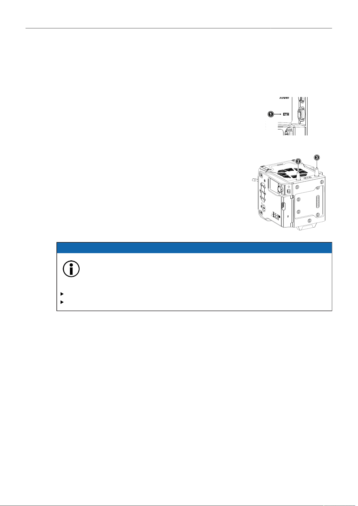
Network 86
20 Network
A network connection can be used to remotely control the camera. The camera's Web Remote, the
Camera Companion App or other applications communicating with the camera via the Camera Access
Protocol (CAP) can be connected to the camera via Ethernet or WiFi.
The Ethernet connector (1) is located on the right side of the camera.
Use the ALEXA ETH/RJ45 (3.0m/9.8ft) KC 153-S (K2.72021.0) cable
to connect the camera to a computer or network.
The camera is equipped with a 2.4 GHz WiFi module and two WiFi
antennas (2, 3), both located on the back of the camera.
The WiFi module of the camera can be configured to act as an ac-
cess point or in infrastructure (client) mode.
ADVICE
Electrostatic Discharge on Open Connector.
The WiFi module might be damaged by electrostatic discharge when leaving the connector
without antenna attached.
Do not leave the antenna connectors open during operation or transport.
Use only the type of antenna originally supplied.
20.1 WiFi Settings
WiFi Power
► Select MENU > System > Network / WiFi > WiFi Power or
► Select Side Display > Settings > WiFi
to enable/disable WiFi.
WiFi Mode
► Select MENU > System > Network / WiFi > WiFi Mode.
The WiFi mode can only be changed while WiFi power is disabled.
Following options are available:
Host The camera acts as an WiFi access point. The SSID of the camera is ALEXA35-xxxxx.
(xxxxx is the five digit serial number of the camera)
Client The camera can connect to a WiFi network and receives it's IP address via DHCP.
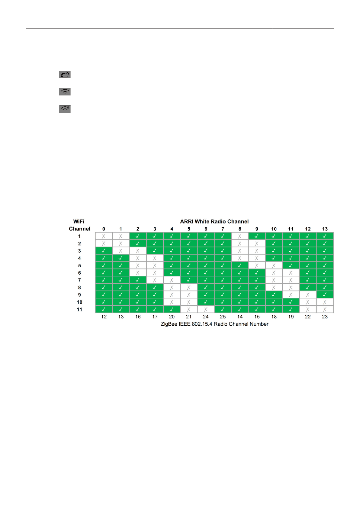
Network 87
Icons on the HOME screen and the Status Info indicate the WiFi status:
Host mode is enabled.
Client mode is enabled, connection to a network has been established.
Client mode is enabled, camera is not connected to a network.
WiFi Host Channel
► Select MENU > System > Network / WiFi > WiFi Host Channel.
► Select Automatic to have the camera automatically select the WiFi host channel with the best
performance, or select a WiFi channel between 1 and 11.
With the Automatic setting, the camera will rediscover the best WiFi host channel each time the
camera is booted or WiFi is turned on. Select Automatic from the list again to trigger a new scan.
When using WiFi and White Radio simultaneously, it is important to configure the used channels
to avoid interference and guarantee optimal performance. The following table gives an overview of
suitable channel configurations:
WiFi Password (Host Mode)
The camera uses WPA-2 encryption and requires a password when connecting to it via WiFi. The
default password is “arriarri”.
► Select MENU > System > Network / WiFi > WiFi Host Password to set the WiFi password. The WiFi
password must be between 8 and 32 characters long.
Connect to a Network (Client Mode)
► Select MENU > System > Network / WiFi > WiFi Network and select the desired network from the
list.
If the selected WiFi network uses encryption, you are prompted to enter the password.
► Enter the password and press CONNECT.
Connect to a Network using a QR Code (Client Mode)
You can use a QR code to connect to a WiFi network. The WiFi credentials need to be provided in the
following format:
WIFI:S:my-ssid;T:[WEP|WPA|WPA2];P:my-password;;

Network 88
where the italic parts need to be replaced with your network credentials.
► Select MENU > System > Network / WiFi > WiFi Network > SCAN QR.
► Hold the QR-Code in front of the lens so that it fills the frame and is in focus.
A popup window with QR-Code data is displayed.
► Press CONNECT.
Disconnect from Network (Client Mode)
► Select MENU > System > Network / WiFi > WiFi Network.
► Press DISCONNECT.
If the network you were connected to is hidden, it will disappear from the network list shortly after.
20.2 Ethernet Settings
LAN IP Mode
► Select MENU > System > Network / WiFi > LAN IP Mode.
Following options are available:
Static Select for manually entering an IP address and subnet mask.
DHCP Select to let the camera accept a dynamically assigned IP address from an DHCP server.
LAN Static IP
► Select MENU > System > Network / WiFi > LAN Static IP to set the desired LAN Static IP adress.
LAN Static Subnet
► Select MENU > System > Network / WiFi > LAN Static Subnet to set the desired LAN Static subnet.
LAN Static Gateway
► Select MENU > System > Network / WiFi > LAN Static Gateway to set the desired LAN Static
gateway.
20.3 Streaming Metadata
The camera supports to stream real time metadata via Ethernet, to be used in virtual studios (aka
volumes with an LED wall, aka mixed reality production systems). For more information please refer to
the ARRI Live Link Metadata Manual, available in the White Papers section on the ARRI website.
Streaming Addressing
► Select MENU > System > Network / WiFi > Streaming Metadata > Streaming Addressing to set the
type of addressing.
Following options are available:
Unicast
Multicast
The metadata is transmitted from the camera to an endpoint via any nodes.
The metadata is transmitted to multiple recipients or to a closed group of recipients.

Network 89
Streaming Address
► Select MENU > System > Network / WiFi > Streaming Metadata > Streaming Address to set the
destination IP address.
Info: When streaming addressing is set to Multicast, the allowed address range is within IP subnet
239.192.0.0/16.
Streaming Port
► Select MENU > System > Network / WiFi > Streaming Metadata > Streaming Port to set the
destination port between 1024 and 65535.
Enable Streaming
► Select MENU > System > Network / WiFi > Streaming Metadata > Enable Streaming to enable
metadata streaming.

Metadata 90
21 Metadata
An ARRI camera automatically collects metadata when shooting. This metadata is stored in the header
of recorded MXF/Apple ProRes and MXF/ARRIRAW files. The data is also stored in separate Avid
Log Exchange ALE files, which keep track of all statics that are recorded on one recording media.
Additionally, ARRI cameras can record lens data dynamically frame-by-frame. Metadata can be
accessed, visualized and exported directly in the ARRI Reference Tool.
For more information about ARRI camera metadata, please refer to the ARRI Metadata White Paper,
available in the White Papers section on the ARRI website.
Production Metadata in Camera Menu
► Select MENU > Metadata > to enter production metadata.

Lens & Electronic Control System (ECS) 91
22 Lens & Electronic Control System (ECS)
22.1 Lens Data
ARRI Lens Data System (LDS)
The Lens Data System (LDS) allows ARRI cameras and accessories to identify connected lenses and
exchange dynamic lens data reflecting the current lens settings. It works with cine lenses using ARRI
LDS or LDS-2 technology, lenses using Cooke /i technology and even cine lenses without lens data
capabilities. LDS also offers basic support for most B4 or PL ENG lenses and Canon photo lenses
when used with the appropriate mount. Available lens information can be displayed live on lens control
units like the Hi-5 or WCU-4, in the camera’s viewfinder and on the monitoring outputs. It is sent with
very low latency via Ethernet for use in mixed reality/virtual production environments and embedded as
ancillary data in the SDI output. Post production benefits from frame accurate dynamic (per frame) and
static (per clip) lens data in all original camera files.
Lenses with ARRI LDS Technology
Most ARRI lenses following the ARRI/Zeiss Ultra Prime LDS have built-in LDS functionality. This offers
basic lens information and accurate lens tables for the Focus, Iris, and Zoom axis (if applicable). LDS
lenses have integrated encoders for each axis and therefore deliver lens metadata even if the lens is
adjusted manually. LDS-2 is the latest generation of the lens data system. It was introduced with the
LPL mount and ARRI Signature Prime and Signature Zoom lenses. LDS-2 offers more bandwidth,
higher precision and faster communication. LDS-2 requires no calibration turn to the end stops of each
lens ring to deliver data. LDS-2 is prepared for future applications and is being licensed to other lens
and camera manufacturers.
Lenses with Cooke /i Technology
Many lenses, camera and lens control system manufacturers rely on /i Technology, which has been
designed and developed by Cooke Optics as an open lens metadata protocol. Every ALEXA camera
with an LDS capable lens mount, including the original ALEXA “Classic”, supports basic /i Technology.
Please note that some older Cooke lenses may be running on outdated firmware. This is likely to
cause incompatibilities with the LDS. Please contact Cooke Optics directly for more information about
checking the lens firmware version and available updates.
Lenses without Lens Data Capabilities
To get the FIZ information for a lens without lens data capabilities, the LDS can derive the lens ring
positions based on end-to-end calibrated lens motor positions and a lens file that is used as a look up
table. These files are available from the Lens Data Archive (LDA), a local library of lens files, which can
also be extended by the user. The LDA exists in ARRI cameras or accessories like the UMC-4, RIA-1,
or cforce mini RF or in the ECS sync app for iOS.
To create a new lens file, you need a camera, lens motors, a HI-5 or WCU-4 wireless lens control unit
and the lens. First, the motors are calibrated to the end stops of their lens rings. Then, axis by axis,
the lens control is used to drive the lens to each marking on the lens barrel and to set markers for the
corresponding motor (encoder) position. Finally, the lens file can be stored by e.g. model, focal length
and optionally lens serial number. Programming a lens file takes a while, but is time well spent, as it can
be shared between LDAs and therefore only needs to be done once.
ARRI Lens Data Mount
Certain non-LDS lenses can be retrofit with an ARRI Lens Data Mount (LDM-2), which is programmed
with the lens file. Using a Lens Data Mount instead of the LDA is more practical where one lens may be
used on many cameras, such as a camera rental operation. It also saves time in production as the LDS
automatically uses the file when the lens is attached.
The LDM-2 is available for Angénieux Optimo 24-290, Angénieux 17-102, Angénieux 25-250, Cooke
25-250, Cooke 18-100 and Zeiss Apo Tessar 300.

Lens & Electronic Control System (ECS) 92
Lens Data Display in Camera
Lens data can be displayed as camera status overlays in the viewfinder and the SDI outputs. Single
overlays for focus distance, iris and focal length are displayed. For further information please see
"Configuration of Status Info Components".
The camera can be configured to display either metric or imperial readings:
► Select MENU > Lens & ECS > Focus Unit to set the desired focus unit.
Following options are available:
Lens Default
Imperial
Metric
Focus unit is displayed according to the markings on the lens (requires LDS or Cooke /i lens).
Focus unit is displayed in Feet.
Focus unit is displayed in Meter.
Circle of Confusion
► Select MENU > Lens & ECS > Circle of Confusion to set the Circle of Confusion.
Following options are available:
0.009
0.013
0.025
22.2 Lens Data Archive
The Lens Data Archive (LDA) is an archive that contains lens tables. In combination with the lens
motor(s) these lens tables provide lens data for lenses without a lens data interface. The lens tables set
the raw motor encoder values in correlation to the actual lens scales. Once you choose the right lens
table from the Lens Data Archive and calibrate your lens motors, you get the same type of lens data
as an LDS lens would deliver. You can create your own lens tables for any given lens with the Hi-5 or
WCU-4 hand units and save them internally, externally to a memory stick, or in an iOS device with the
ECS Sync App. Lens tables can then be transferred wirelessly from the hand units to the camera.
Adding Lens Tables from the USB Medium
► Select MENU > Lens & ECS > Lens Data > Lens Tables Installed > ADD.
► Press IMPORT to import lens tables from a USB medium or DEFAULTS to select a lens table from
the internal lens tables default list.
► Select the desired lens table from the list and press IMPORT.
The lens table is imported to the camera's Lens Tables Installed list.
► To use the lens table, select the lens table from the Lens Tables Installed list and press SET.
Some lens tables contain different scale classes for the same lens model. The scale class of an
individual lens is engraved on the lens barrel. If required: select the corresponding scale class from
the list.
It is possible to load a lens table even when an LDS lens is attached. The LDA values calculated
from motor positions and lens tables take precedence over the values communicated by the lens
itself. This can be necessary if the lens data from the lens is faulty or imprecise.
As soon as an LDA table is activated, the LDS contacts of the lens mount are switched off,
indicated through the LDS icon on the HOME screen and in the Status Info.
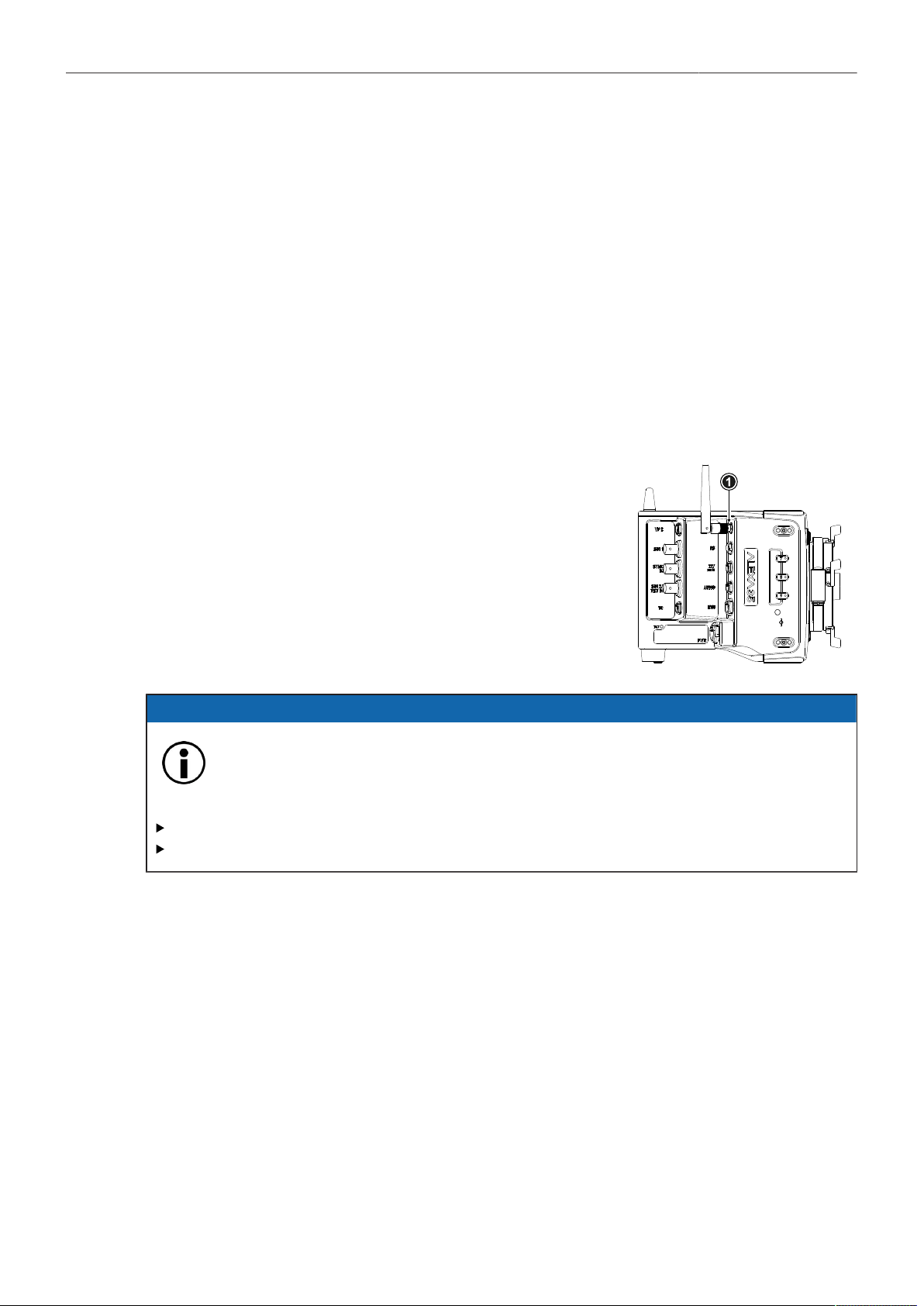
Lens & Electronic Control System (ECS) 93
Lens Tables Favorites List
Frequently used lens tables can be added to a favorites list. The list shows all lenses that have been
added before, including the selected scale class.
Add Lens Tables to the Favorites List
► Select MENU > Lens & ECS > Lens Data > Lens Tables Installed and select and set a lens table for
use.
► Select MENU > Lens & ECS > Lens Table > Add to Favorites to add the lens table to the favorites
list.
Select a Lens Table from the Favorites List
► Select MENU > Lens & ECS > Lens Data > Lens Table Favorites and select and set a lens table
from the list.
22.3 White Radio Configuration
The camera has an integrated radio unit via which the ARRI HI-5,
WCU-4 and SXU-1 hand held units can be connected to the cam-
era. It enables wireless lens control, lens data communication
and remote control of basic camera functions. The radio system
is referred to as white radio. The connector for the white radio an-
tenna is located on the right side of the camera (1).
In order to assume a correct wireless operation, please ensure
that the white radio antenna is installed correctly on the camera.
ADVICE
Electrostatic Discharge on Open Connector.
The White Radio module might be damaged by electrostatic discharge when leaving the
connector without antenna attached.
Do not leave the antenna connectors open during operation or transport.
Use only the type of antenna originally supplied.
Radio Power and Radio Channel
► Select MENU > Lens & ECS > Radio > Power to enable white radio.
► Select MENU > Lens & ECS > Radio > Channel to select the white radio channel.
Following options are available:
Channel Frequency ZigBee IEEE
802.15.4 Channel
0
1
2
3
4
5
6
2.410 GHz
2.415 GHz
2.430 GHz
2.435 GHz
2.450 GHz
2.455 GHz
2.470 GHz
12
13
16
17
20
21
24
Channel Frequency ZigBee IEEE
802.15.4 Channel
7
8
9
10
11
12
13
2.475 GHz
2.420 GHz
2.425 GHz
2.440 GHz
2.445 GHz
2.460 GHz
2.465 GHz
25
14
15
18
19
22
23

Lens & Electronic Control System (ECS) 94
Active white radio and set channel number is indicated through the white radio icon dis-
played on the HOME screen as well as in the Status Info.
To connect a hand unit to the camera set the hand unit's radio channel to the same value. Make
sure that each camera on set uses its own white radio channel. It is not supported that one hand
unit connects to two cameras in parallel.
Info: When using white radio and WiFi simultaneously it is important to configure the used channels
to avoid interference and guarantee optimal performance. See the channel configuration table in the
WiFi chapter "WiFi Host Channel" for more information.
► MENU > Lens & ECS > Radio > Status shows the current status of the white radio module:
Off
Init
Ready
Blocked
White Radio is disabled.
White Radio is initializing
White radio is initialized and ready to be used.
Selected White Radio channel is already used by another camera on set.
► MENU > Lens & ECS > Radio > Connected Devices displays the amount of hand units connected
to the camera. Up to three hand units can connect to one camera in parallel.
Region Setting
The wireless region setting specifies the region the white radio can be used in compliance with local
regulations.
ADVICE
Please ensure that the region is configured correctly, as it may be illegal to use White Radio in a
region other than specified in the setting. All settings are compliant to FCC and IC regulations.
► Select MENU > Lens & ECS > Radio > Wireless Region Setting to set the region.
The following options are available:
Australia
Canada
China
Egypt
Europe
Hong Kong
India
Israel
Japan
New Zealand
Philippines
Singapore
South Africa
South Korea
Taiwan
Thailand
UAE
USA
World
► Select World if your specific region is not listed.
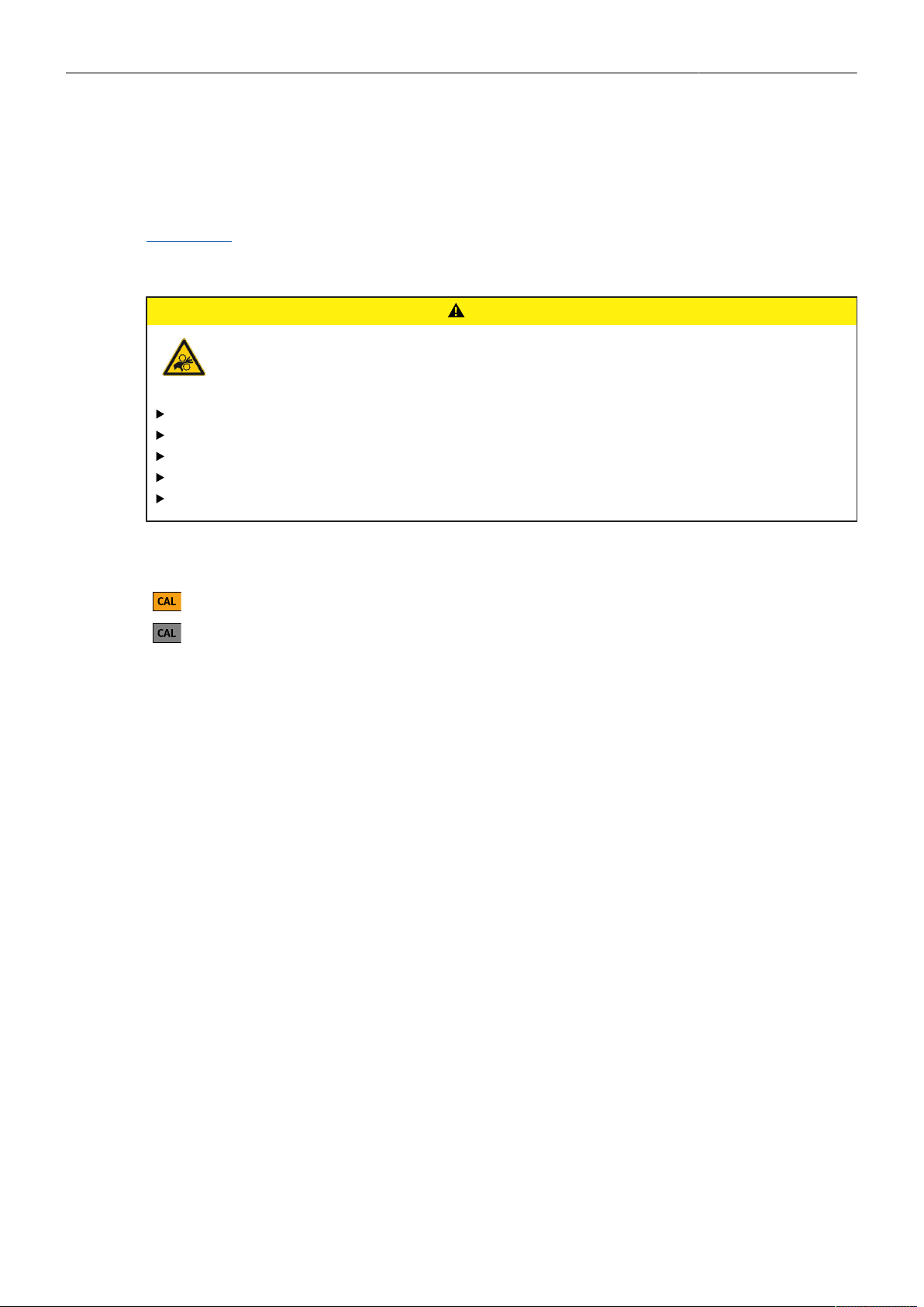
Lens & Electronic Control System (ECS) 95
22.4 Lens Motors
The camera supports the use of cforce mini, cforce plus and cforce mini RF lens motors. Lens motors
are connected to the LBUS connector of the camera and/or the lens mount and can be daisy chained.
For more information about lens motors, please download the lens motor user manuals from the
Lens Motors section of the ARRI website.
Motor Calibration
CAUTION
Rotating Lens Motor
Risk of crushing fingers and capturing and unraveling long hair, jewelry and/or clothing.
Make sure that the lens motor is properly attached to the lens.
Do not touch the lens motor gears while they are moving.
Keep hair and loose clothing away from the motor gear teeth.
Keep cables connected to the camera away from the motor gear teeth.
Do not trigger a calibration unless all connected motors are attached to the lens.
After a lens motor has been connected to the camera, it must first be calibrated before it can be used.
The camera indicates the calibration request by displaying an orange CAL icon on the HOME
screen as well as in the Status Info. The icon turns gray once calibration is in progress, and
expires when calibration has finished.
► Select MENU > Lens + ECS > Calibrate All Motors to start calibration of all connected lens motors.
Alternatively, motor calibration can be triggered via the hand unit or the motor itself.
Motor Torque
► Select MENU > Lens & ECS > LBUS Lens Motor Configuration Focus / Iris / Zoom Motor Torque to
set the torque of a lens motor in the range of 1 (the lowest torque) to 4 (the highest torque).
Motor Direction
► Select MENU > Lens & ECS > LBUS Lens Motor Configuration Focus / Iris / Zoom Motor Direction
to set the motor direction between Left and Right.
Use Left if a lens motor is to the left of the lens, use Right if it is to the right.
Teeth Count
The motor teeth count setting is only active when an LDA lens table is active and is used to assure
correct lens table mappings when using a different motor gear than the one the lens table was initially
created with. The number of teeth can be read on the gear wheel of the motor.
► Select MENU > Lens & ECS > LBUS Lens Motor Configuration Focus / Iris / Zoom
Motor Teeth Count to set the teeth count.
Following options are available:
Auto
40t
50t
60t
The camera determines the teeth count during motor calibration.
The motor is equipped with a 40 tooth gear.
The motor is equipped with a 50 tooth gear.
The motor is equipped with a 60 tooth gear.
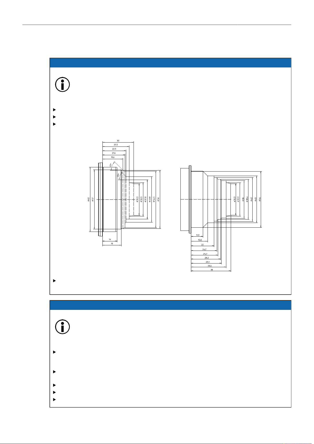
Lens & Electronic Control System (ECS) 96
22.5 Changing a Lens
ADVICE
Risk of damage and injury when using lenses exceeding the supported entry depth!
LPL mount lenses with more than 30.00 mm entry depth and PL mount lenses with more
than 38.00 mm entry depth might damage the camera's internal filters. Shards from broken
filter glass might cause injury.
Do not use LPL mount lenses with more than 30.00 mm entry depth.
Do not use PL mount lenses with more than 38.00 mm entry depth.
Use only lenses that do not exceed the following dimensions (left: LPL mount lenses, right: PL
mount lenses):
To ensure maximum allowable lens mounting depth always have your camera and lenses
shimmed correctly.
ADVICE
Dust particles on the sensor cover glass may affect the recorded image!
When no lens or lens cap is attached to the camera, dirt and dust particles may enter the
camera and settle on the sensor cover glass. Particles on the sensor cover glass can later
be visible in the recordings made by the camera.
Changing lenses or lens mounts should be done in a dry and dust free environment. If this is not
possible, take extra care that no particles enters the camera while the lens or the lens mount is
off.
After removal of a lens, perform a dust check to make sure no particles have settled on the
sensor cover glass.
Place the protective cap on the lens mount, when no lens is attached to the camera.
Always store the camera with a capped lens mount or camera front cover installed.
Make sure to protect all optical surfaces when changing a lens or lens mount.
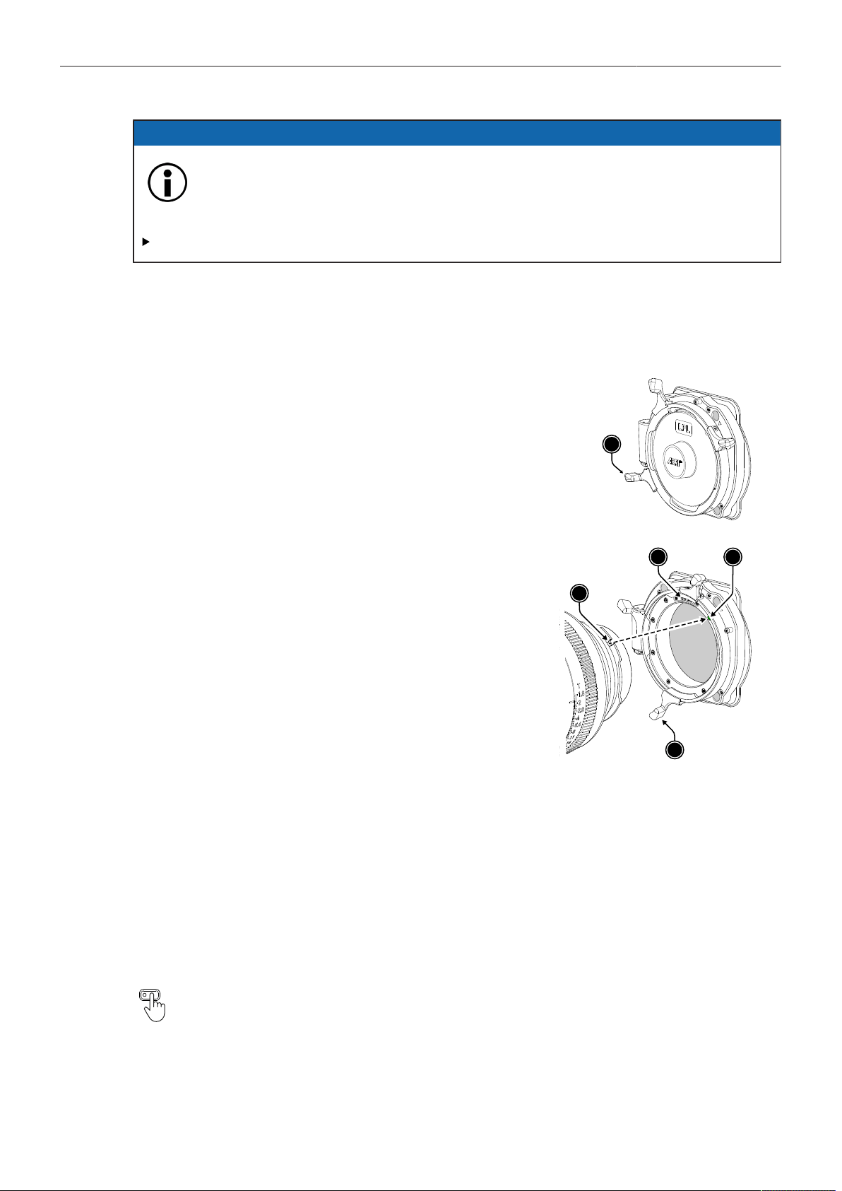
Lens & Electronic Control System (ECS) 97
ADVICE
Heavy Lenses may affect the flange focal depth!
Using lenses above 3 kg / 6.6 lbs without a proper lens support can put stress on the lens
mount and affect the flange focal depth.
Always use a suitable lens support for lenses weighing more than 3 kg / 6.6 lbs.
Lens change on the LPL mount, the PL mounts as well as the PL-to-LPL Adapter works the
same way. The description below shows an LPL mount.
► When removing a lens, hold the lens securely.
► Turn the bayonet ring (1) anticlockwise until it stops.
► Gently remove the lens / lens port cap from the lens
mount.
1
► Carefully insert the lens into the lens mount. Align the
notch in the lens flange (1) with the index pin on the
lens mount (2), keeping the lens rotated into a position
where the lens markings are visible from either side of
the camera.
► When attaching an LDS lens, make sure it is oriented
so that the LDS contacts of the lens and lens mount (4)
meet (12:00 position). Do not touch the LDS contacts.
► Carefully press the lens flange flat onto the lens mount.
► Turn the bayonet ring (3) clockwise until the lens is
locked securely.
1
2
3
4
22.6 EF Lens Iris Adjustment
When using EF Mount and EF lenses, the aperture of the lens can be controlled from the camera
menu. This option is only available when the camera is equipped with an EF Mount. Furthermore, the
iris of EF lenses can be controlled using the ARRI Master Grips or the Operator Control Unit OCU-1.
► Select HOME > EI > Iris.
► Rotate the jogwheel to open or close the iris of the EF lens. Press the jogwheel to toggle between
full stops and sub stops.
Info: Sub stop precision depends on the lens type and is automatically set by the camera.
User Buttons EF Close Iris and EF Open Iris support to quickly adjust the iris of an EF lens.

Lens & Electronic Control System (ECS) 98
22.7 Enable Lens Mount
You can disable the LDS contacts of the lens mount. Usually this is not necessary, but it can be helpful
when e.g. lenses with faulty lens data are used. Please note that as soon as an LDA lens table is
activated, the LDS contacts of the lens mount are switched off automatically. There is no need to switch
the mount off manually when using LDA lens tables.
► Select MENU > Lens & ECS > Enable Lens Mount to enable/disable the lens mount contacts of the
lens mount.
A disabled lens mount is indicated through the LDS icon on the HOME screen as well as in the
Status Info.
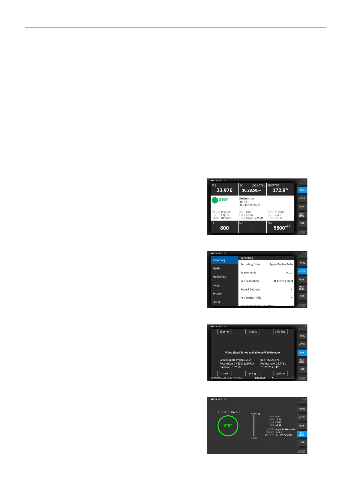
Remote Control 99
23 Remote Control
23.1 Web Remote
The camera can be remotely controlled via WiFi or Ethernet using the camera's Web Remote feature.
► Connect the camera to your computer via WiFi or Ethernet.
► Open a web browser and enter the URL ALEXA35-xxxxx.local (replace xxxxx with the camera's 5-
digit serial number).
To use the Web Remote via this URL, the device must support zero-configuration networking
(zeroconf), e.g. through Apple Bonjour. Without zeroconf, the Web Remote can be reached via the
network's IP address (WiFi or LAN IP). The WiFi IP is fixed to 192.168.153.1. The LAN IP can be
either assigned from a DHCP server or configured manually, and can be checked in MENU > Info >
Network Info or the Info page of the side display.
HOME
Shows the camera HOME screen (as on MVF-2)
with access to the main parameters.
MENU
Access to the camera menu.
PLAY
Starts playback from the recording medium. Pro-
vides the same controls as the MVF-2, but does
not show a video signal.
REC / INFO
Contains information on the main recording pa-
rameters, plus a REC button. Click the big circle
icon to start/stop recording.
Info: Rec status and timecode may respond
slightly delayed depending on the network's
speed.

Remote Control 100
USER
Shows configuration of the camera user buttons
and allows you to trigger them. Press the number
icons to trigger the user buttons.
ADVICE
Frequent reloading of the Web Remote camera interface connected with WiFi indicates a limited
WiFi range. Please place the device closer to the camera or connect via Ethernet. You may also
consider to use the WiFi client mode which allows connecting the camera to a WiFi network.
After a camera update, the Web Remote feature may not be fully functional until the browser cache
of your web browser has been cleared. Always use a 'private' or 'incognito' browser window when
using the Web Remote to operate the camera and to perform a SUP update. This prevents possible
erroneous behavior.
23.2 Camera Access Protocol (CAP)
The Camera Access Protocol (CAP) is an IP based API used to control and monitor ARRI cameras
via a network connection. The protocol incorporates functions to perform color grading, query and set
values like exposure index or sensor frame rate, start and stop recording and many more. Information
on the Camera Access Protocol is available through the ARRI Partner Program free of charge. For
more details please see our ARRI Partner Program and the Camera Access Protocol Feature List in the
White Papers section on the ARRI website.
Activation of CAP Server
► Select MENU > System > Camera Access Protocol (CAP)
to switch remote access to the camera via the Camera Access Protocol on or off.
CAP Server Password
► Select MENU > System > Camera Access Protocol (CAP) > Cap Server Password.
► Use the on-screen keyboard to enter a password used for Camera Access Protocol connections.
CAP Client List
The CAP client list shows the name of the currently connected client. The list shows 'NONE' if no client
is connected, and 'NO NAME' if the connected client has not transmitted its name.
► Select MENU > System > Camera Access Protocol (CAP) > CAP Client List to display the list.
23.3 Camera Companion App
The Camera Companion App offers remote control of one or multiple cameras, as well as customization
of the app's user interface. It focuses on the functions that are most frequently used during production.
The app uses the Camera Access Protocol (CAP) via the camera's internal WiFi radio or the ETH
interface. The app is available for download from the Apple App Store and can be used on iPhone,
iPad, M1 and M2 Mac computers and the Apple watch.

Remote Control 101
23.4 Hand Units Hi-5 and WCU-4
The ARRI hand units Hi-5 and WCU-4 support to control basic settings of the camera. The following
settings can be accessed through the hand units:
Rec start/stop
Full Playback Control
Sensor Frame Rate
Shutter Angle
Exposure Index
White Balance
ND Filter
Peaking
Surround View
Status Info
False Color
Frame Lines
User Buttons
User Setups
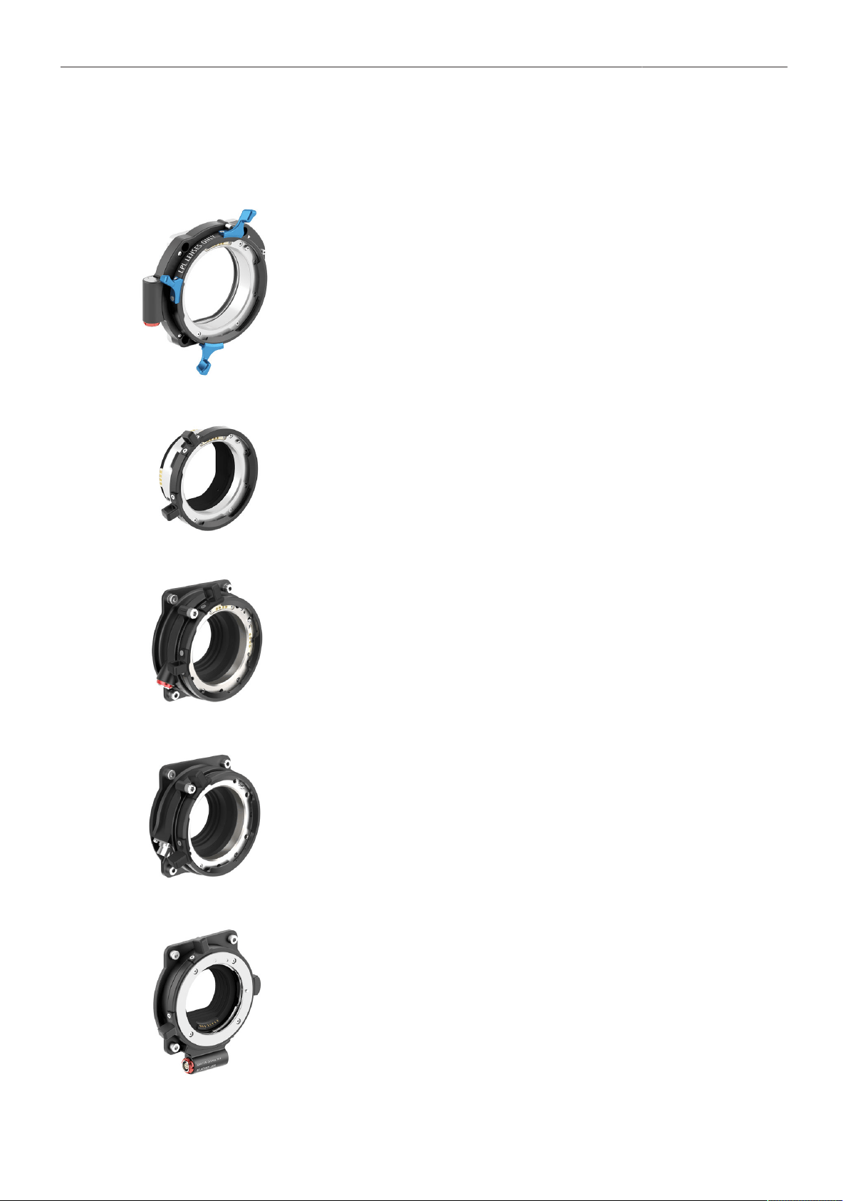
ALEXA 35 Accessories 102
24 ALEXA 35 Accessories
24.1 Lens Mounts
ARRI LPL Mount (LBUS) K2.0018983
A lens mount specifically designed for large format and/or full frame lenses with an
LPL (Large Positive Lock) mount. Compatible with ARRI LDS-2 and Cooke /i. Can be
equipped with the PL-to-LPL Adapter to accept PL mount lenses. Includes an LBUS con-
nector for cforce-type lens motors. In comparison to the PL mount, the LPL mount has
a wider diameter (62 mm vs. 54 mm) and a shorter flange focal distance (44 mm vs. 52
mm). Optimized for the increased dynamic range of the ALEXA 35 sensor.
PL-to-LPL Adapter K2.0016936
An adapter that can be used to attach PL mount lenses to a camera with an LPL mount.
Compatible with ARRI LDS-1 and Cooke /i. The adapter can be mounted either so that
the LDS contacts are in the 12:00 position for ARRI lenses, or so that the LDS contacts
are in the 3:00 position for Cooke lenses.
PL Mount (LBUS) K2.0042651
A PL lens mount with an LBUS connector optimized for the increased dynamic range of
the ALEXA 35 sensor. Reduced internal reflection properties ensure that the full contrast
of the image from the lens reaches the sensor. The PL Mount (LBUS) is compatible with
ALEXA 35, ALEXA Mini LF, ALEXA Mini and AMIRA, but only ALEXA 35, ALEXA Mini
LF and ALEXA Mini support the LBUS connector. Replaces the older “Titanium PL LDS
mount with LBUS (K2.0003216)“.
PL Mount (Hirose) K2.0042652
A PL lens mount with a Hirose connector optimized for the increased dynamic range of
the ALEXA 35 sensor. Reduced internal reflection properties ensure that the full contrast
of the image from the lens reaches the sensor. The PL Mount (Hirose) is compatible with
ALEXA 35, ALEXA Mini LF, ALEXA Mini and AMIRA. Replaces the older “PL LDS Lens
Mount (Hirose) (K2.0001107)“.
EF Mount (LBUS) K2.0019965
An EF lens mount with an LBUS connector optimized for the increased dynamic range of
the ALEXA 35 sensor. Reduced internal reflection properties ensure that the full contrast
of the image from the lens reaches the sensor. This EF Mount (LBUS) has a wide light
baffle that illuminates both Super 35 and large format sensor areas. Allows control of the
electronic iris in many EF lenses through the camera menu and ARRI ECS devices. Also
allows the use of the electronic Image Stabilization found in some EF lenses.
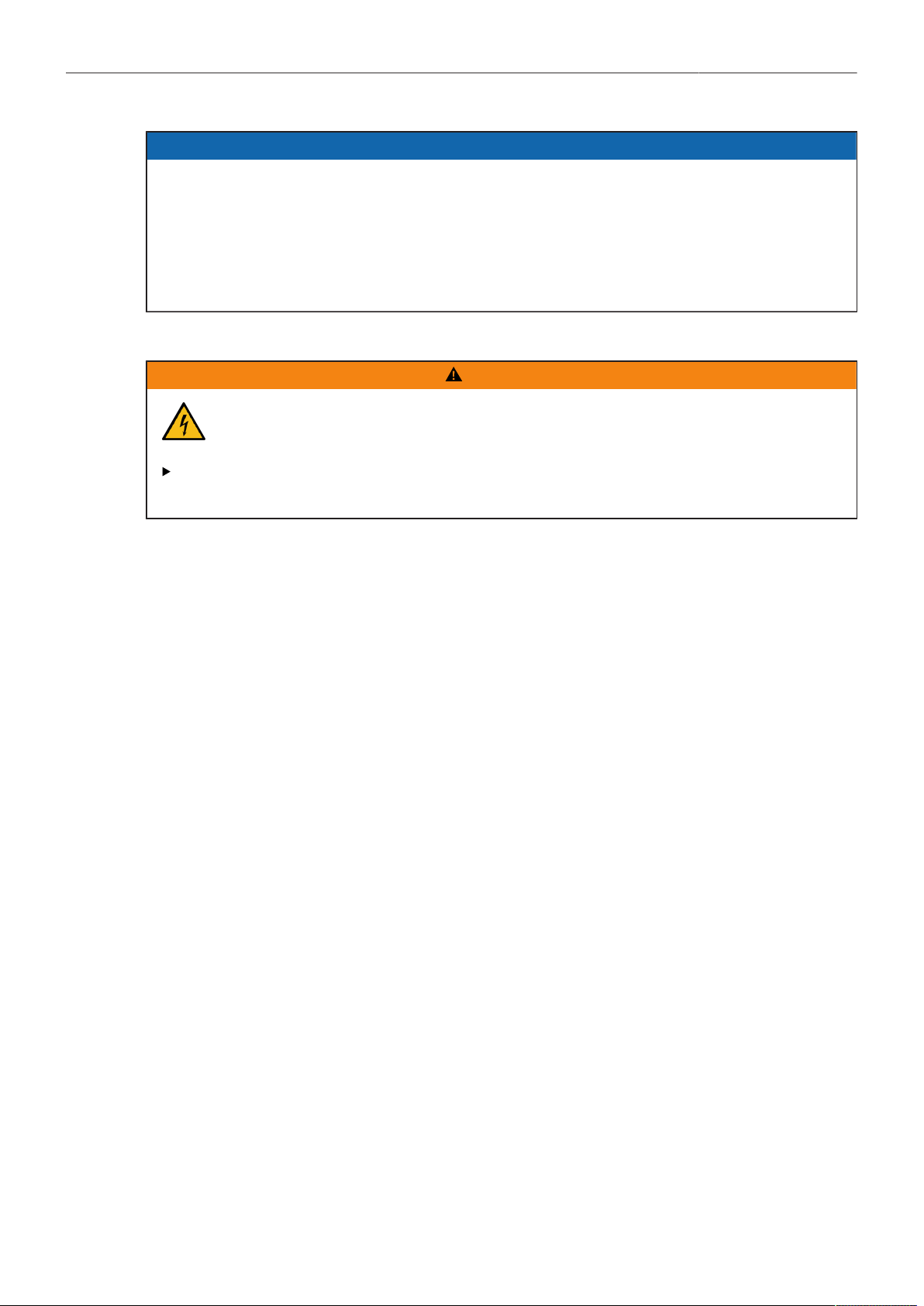
ALEXA 35 Accessories 103
ADVICE
The Titanium PL LDS Mount with LBUS (K2.0003216), the AMIRA PL LDS Lens Mount
(K2.0001107) and the EF Lens Mount (K2.0001103) are mechanically compatible with the ALEXA
35, but these lens mounts are not sufficiently stray light optimized to be used with the ALEXA 35.
New lens mounts specifically designed for the ALEXA 35 (PL Mount (LBUS) (K2.0042651), PL
Mount (Hirose) (K2.0042652), EF Mount (LBUS) (K2.0019965) ensure that the high dynamic range
of the sensor is not compromised by stray light that may be generated in the optomechanics of the
camera.
24.1.1 Changing the Lens Mount
WARNING
Changing the Lens Mount while the Camera is Powered
Risk of electric shock and permanent damage to the camera and/or the lens mount.
Always switch off the camera and disconnect all power supplies before changing the lens
mount.
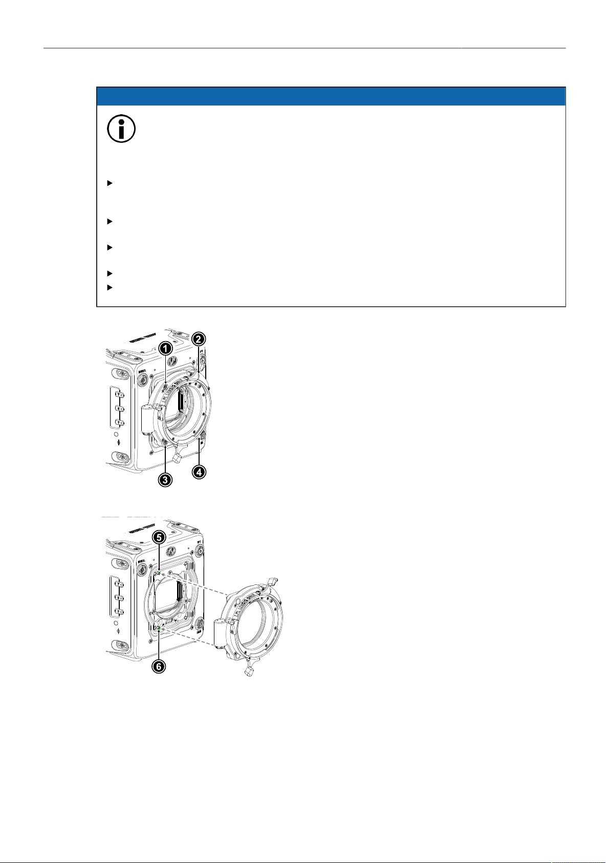
ALEXA 35 Accessories 104
ADVICE
Dust particles on the sensor cover glass may affect the recorded image!
When no lens or lens cap is attached to the camera, dirt and dust particles may enter the
camera and settle on the sensor cover glass. Particles on the sensor cover glass can later
be visible in the recordings made by the camera.
Changing lenses or lens mounts should be done in a dry and dust-free environment. If this
is not possible, take extra care that no particles enters the camera while the lens or the lens
mount is off.
After removal of a lens, perform a dust check to make sure no particles have settled on the
sensor cover glass..
When no lens is attached to the camera, use the lens port cap to prevent dust from entering
the lens cavity.
Always store the camera with a capped lens mount or camera front cover installed.
Make sure to protect all optical surfaces when changing a lens or lens mount.
► Switch off the camera and unplug any power source.
► Crosswise, loosen all four lens mount screws with a 3.0 mm
Allen key.
► Carefully remove the lens mount (or camera front cover).
► Store the lens mount in a case for dust protection.
► Carefully align the lens mount with the
two guiding pins (5, 6) on the camera's
lens mount base.
► Crosswise, hand-tighten all four lens
mount screws with a 3.0 mm Allen key.

ALEXA 35 Accessories 105
ADVICE
When adjusting the flange focal depth on the LPL
mount make sure to insert the shims in the correct
orientation. Inserting the shims in the incorrect ori-
entation (flipped) may result in a short circuit on the
LDS print, compromising LDS functionality (lens de-
tection and lens data).
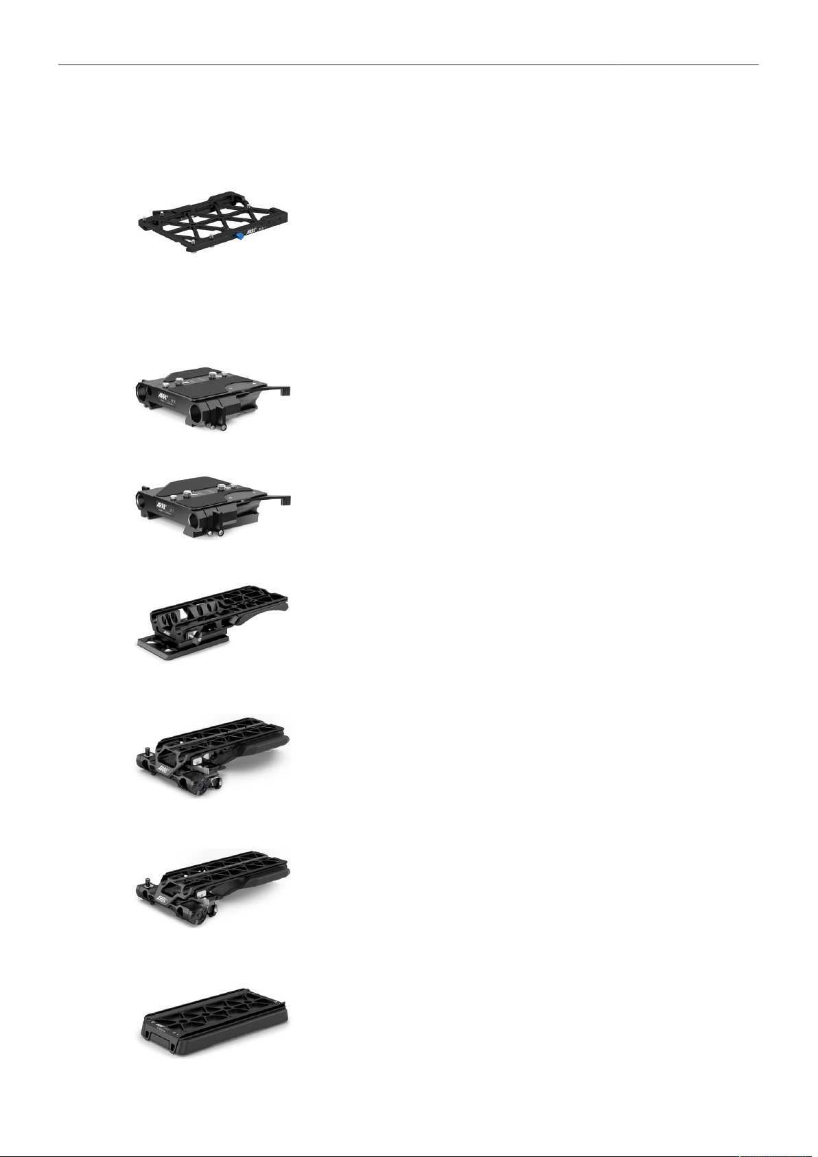
ALEXA 35 Accessories 106
24.2 Mechanical Accessories
24.2.1 Bottom Accessories
Balance Utility Dovetail BUD-1 K2.0034180
The super small and lightweight Balance Utility Dovetail BUD-1 attaches to the ALEXA
35 bottom. Once mounted to the camera, the BUD-1's wide dovetail allows the cam-
era to be securely and quickly attached and detached from and to all ALEXA 35 acces-
sories that sit below the camera including the CBP-5, CBP-6, BPA-6, CSP-2 and SAM-5
through 9.
Additionally, the dovetail allows balancing of the camera on the accessories. Use the
lever to lock or unlock the sliding option. Push in the blue safety button to slide the
ALEXA 35/BUD-1 off whatever it is mounted on. Furthermore, keeping the BUD-1 at-
tached to the camera ensures that the camera's air intake is not covered.
Bridge Plate BP-8 K2.0031436
The venerable Bridge Plate BP-8 sits between a Bridge Plate Adapter and the ARRI bot-
tom dovetail plate and allows balancing of the camera. The BP-8 accepts two 19 mm
studio rods without restrictions regarding forward and backward positioning of the rods.
Bridge Plate BP-9 K2.0031435
The venerable Bridge Plate BP-9 sits between a Bridge Plate Adapter and the ARRI bot-
tom dovetail plate and allows balancing of the camera. The BP-9 accepts two 15 mm
studio rods without restrictions regarding forward and backward positioning of the rods.
Bridge Plate Adapter BPA-6 K2.0024745
While the Compact Bridge Plates represent the fastest, most comfortable and flexible
method to change from tripod to shoulder and to other camera supports, the BPA-6 pro-
vides an option for those who want to use tripods with “Touch and Go” plates or the clas-
sic ARRI Bridge Plates BP-8 or BP-9. The BPA-6 dovetail slides into the bottom of the
Balance Utility Dovetail BUD-1. The bottom of the BPA-6 is a “Touch and Go 35” plate
that allows quick mounting to a variety of tripod heads.
Compact Bridge Plate CBP-5 K2.0023549
The CBP-5 is a compact and lightweight base plate that combines the features of a slid-
ing studio bridge plate with a comfortable Visco shoulder pad. Its unique quick-release
system allows the CBP to be lifted straight off (or placed on) the bottom dovetail plate
without having to slide it off (on). The Compact Bridge Plates represent the fastest, most
comfortable and most flexible method to change from tripod to hand held and to other
camera supports. The CBP-5 accepts 19 mm studio rods and 15 mm Lightweight rods.
Compact Bridge Plate CBP-6 K2.0023836
The CBP-6 is a compact and lightweight base plate that combines the features of a slid-
ing studio bridge plate with a comfortable Visco shoulder pad. Its unique quick-release
system allows the CBP to be lifted straight off (or placed on) the bottom dovetail plate
without having to slide it off (on). The Compact Bridge Plates represent the fastest, most
comfortable and most flexible method to change from tripod to hand held and to other
camera supports. The CBP-6 accepts 15 mm studio rods and 15 mm Lightweight rods.
Compact Shoulder Pad CSP-2 K2.0024161
The CSP-2 is a simple flat shoulder pad with a long, comfortable Visco pad. Its four (re-
movable) metal feet allow the camera to be safely placed on any flat surface when not
on the operator's shoulder.The CSP-2 slides into the bottom of the Balance Utility Dove-
tail BUD-1.
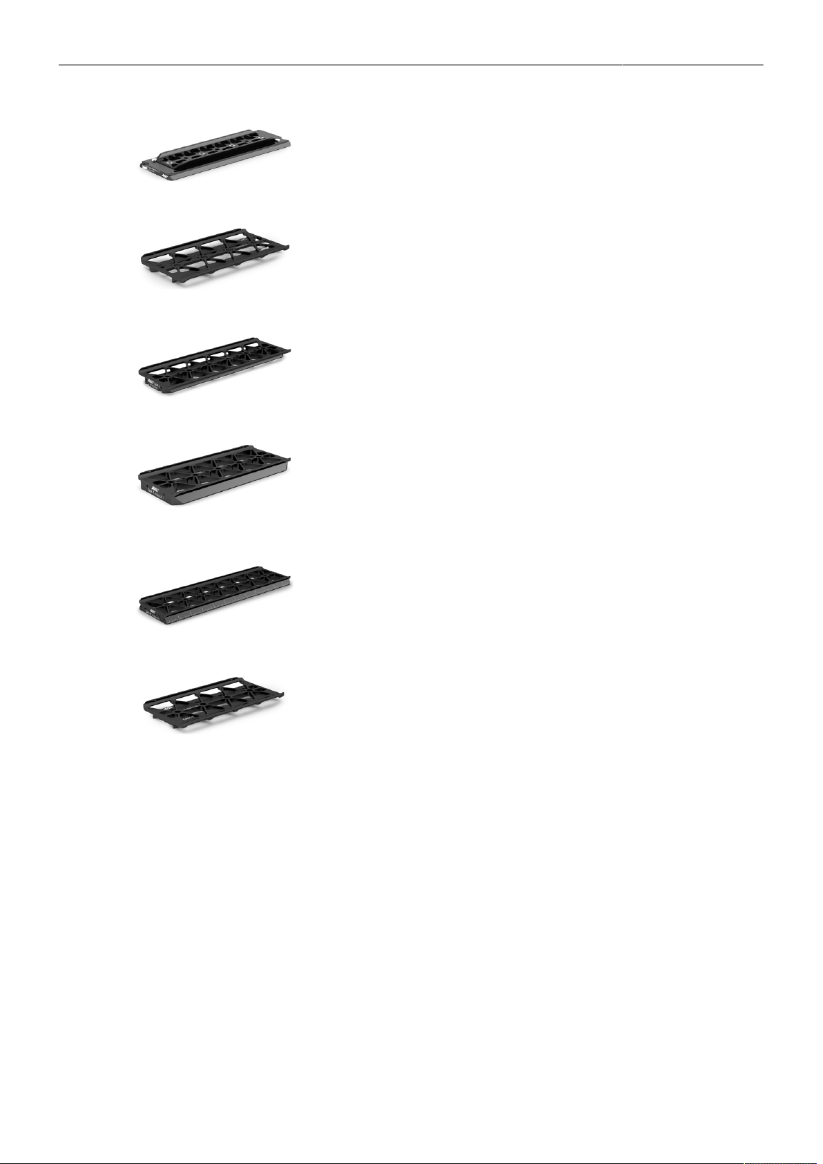
ALEXA 35 Accessories 107
Bottom Plate 300 mm/12“ K2.0015896
The 300 mm/12 inch Bottom Dovetail Plate is the standard for all prime lenses where
minimal balancing is required.
Stabilizer Adapter Mount SAM-5 K2.0024572
The Stabilizer Adapter Mount SAM-5 is a sliding dove tail plate with a very small height
that connects the ALEXA 35 to a MōVI Pro or M15. The SAM-5 top dove tail slides into
the bottom of the Balance Utility Dovetail BUD-1. The SAM-5 bottom is a rail that slides
into the top stage of the MōVI Pro or M15.
Stabilizer Adapter Mount SAM-6 K2.0024508
The Stabilizer Adapter Mount SAM-6 is a low profile sliding dove tail plate that connects
the ALEXA 35 to ARRI CSS products, such as ARRI TRINITY and SRH-3/360. The
SAM-6 top dove tail slides into the bottom of the Balance Utility Dovetail BUD-1. The
SAM-6 bottom is a dove tail that slides into the top stage of any ARRI CSS product.
Stabilizer Adapter Mount SAM-7 K2.0024511
The Stabilizer Adapter Mount SAM-7 is a low profile sliding dove tail that connects the
ALEXA 35 to ARRI Artemis and GPi PRO Stabilizers. The SAM-7 top dove tail slides in-
to the bottom of the Balance Utility Dovetail BUD-1. The SAM-7 bottom is a dove tail that
slides into the top stage of any stabilizer system using the GPi Pro standard (including
the ARRI Artemis).
Stabilizer Adapter Mount SAM-8 K2.0044479
The Stabilizer Adapter Mount SAM-8 is a low profile sliding dove tail plate that connects
the ALEXA 35 to Tiffen Steadicam products, such as M1 and M2. The SAM-8 top dove
tail slides into the bottom of the Balance Utility Dovetail BUD-1. The SAM-8 bottom is a
dove tail that slides into the stage of Tiffen Steadicams.
Stabilizer Adapter Mount SAM-9 K2.0041949
The Stabilizer Adapter Mount SAM-9 is a low profile sliding dove tail that connects the
ALEXA 35 to DJI Ronin 2. The SAM-9 top dove tail slides into the bottom of the Balance
Utility Dovetail BUD-1. The SAM-9 bottom is a dove tail that slides into the stage of DJI
Ronin products.
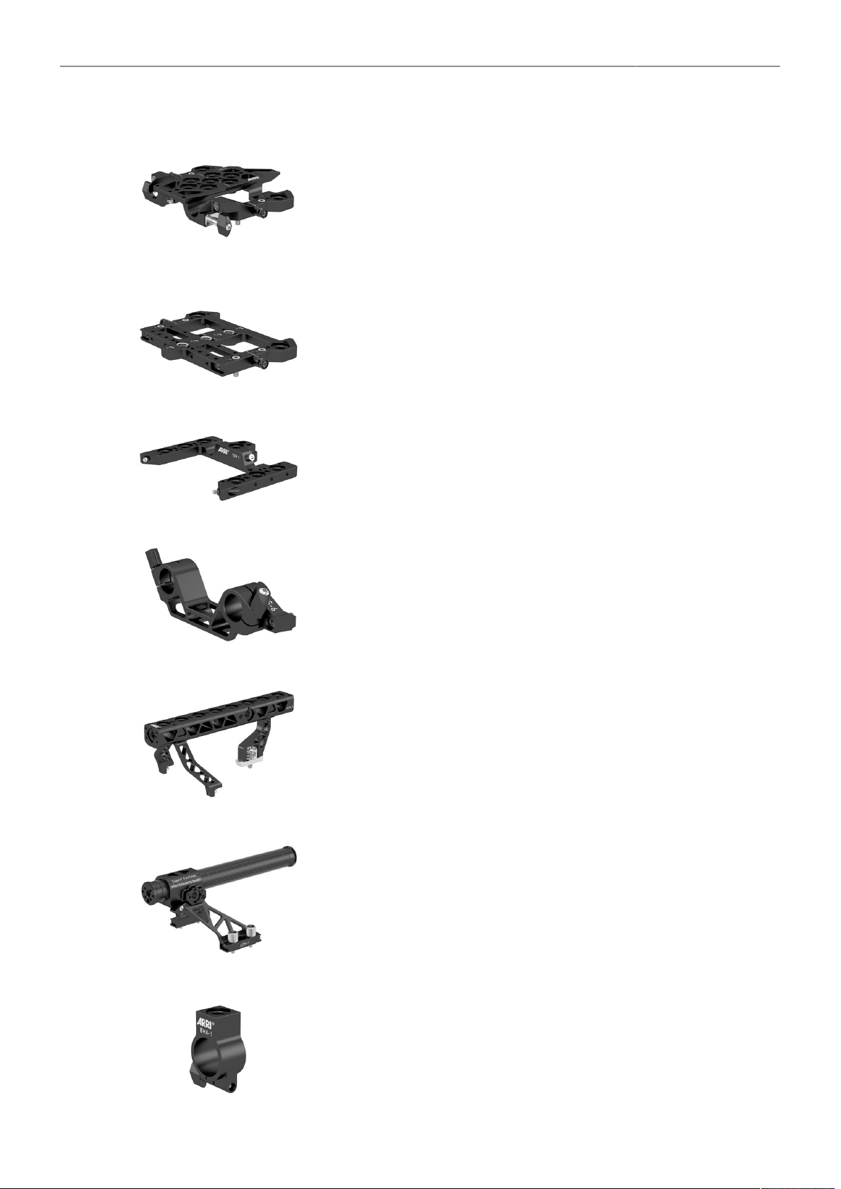
ALEXA 35 Accessories 108
24.2.2 Top Accessories
Low Mode Support LMS-4 K2.0034178
The Low Mode Support LMS-4 is a fully featured top plate for the ALEXA 35. A new
quick release mechanism allows the CCH-5 top handle to be easily removed, without
tools, while retaining superior rigidity while mounted. Dual rod clamps for optically cen-
tered 15 mm rods allow for top mounted motors or traditional viewfinder mounting brack-
ets. Multiple mounting points support a range of accessories and low mode mounting for
the ARRI Artemis and other mechanical stabilizers. For even more mounting options, the
LMS-4 can be extended with the TEB-1.
Universal Adapter Plate UAP-3 K2.0034179
The Universal Adapter Plate UAP-3 is a small and flat staging platform for the ALEXA
35 top accessories, including the Lightweight Camera Handle LCH-1 and Center Cam-
era Handle CCH-2. For more mounting options, the UAP-3 can be extended to the back
with the TEB-1. The UAP-3 can also be attached to the base of the camera when an ul-
tra slim mounting plate is required for small rigging scenarios.
Top Extension Bracket TEB-1 K2.0024062
The Top Extension Bracket TEB-1 extends the Low Mode Support LMS-4 or Univer-
sal Adapter Plate UAP-3, so more accessories, including the Rear Accessory Bracket
RAB-2 and Articulated Mounting Plate AMP-1, can be mounted to the camera's top and
back.
Lightweight Support LWS-6 K2.0023948
The LWS-6 holds two 15 mm lightweight support rods. It is designed as an option to add
lightweight rods to the Lightweight Camera Handle LCH-1 or to the Universal Adapter
Plate UAP-3. When attached, rods are optically centered based on the lightweight rod
standard and allow mounting further accessories like the Mini Viewfinder Bracket MVB-1,
lens motors or matte boxes.
Center Camera Handle CCH-5 K2.0023519
The Center Camera Handle CCH-5 is a full size production top handle that can be quick-
ly attached and removed from the LMS-4 without tools. Featuring a wider, more com-
fortable grip than previous top handles the CCH-5 has been designed to allow common
gimbal top plates to remain mounted to the camera, under the handle. Multiple mounting
points adorn the handle for accessories and existing HEB and HEX handle extensions
can be mounted to the front and rear.
Lightweight Camera Handle LCH-1 K2.0024066
The Lightweight Camera Handle LCH-1 is a lightweight carbon fibre top handle for car-
rying the ALEXA 35 and for mounting accessories. It can be quickly attached to or re-
moved from the camera's top or the Universal Adapter Plate UAP-3 without tools, and
the handle post can be slid forward and backwards in order to balance the camera in
your hand.
Balance Harness Adapter BHA-1 K2.0034554
The Balance Harness Adapter BHA-1 allows the secure attachment and rapid balancing
of the ALEXA 35 when using various camera suspension harnesses. The BHA-1 slips
over the handle of the Lightweight Camera Handle LCH-1 and can be slid forwards and
backwards with a simple thumbscrew. It features a 3/8-16 threaded hole for connection
and can also be used to mount accessories to the top handle.
ALEXA 35 Accessories 109
Viewfinder Mounting Bracket VMB-5 K2.0033859
The Viewfinder Mounting Bracket VMB-5 offers a longer reach than traditional viewfind-
er brackets and is the most flexible and comfortable method to attach a viewfinder to a
camera. Positioning the viewfinder in a 360° arc is done by loosening a single thumb
screw and freely repositioning the viewfinder, which will remain in place thanks to double
friction based clamping mechanisms.The VMB-5 is compatible with all standard ARRI
viewfinder extension brackets and viewfinder adapters. Requires SAS-1 for attachment
to a camera.
Square Accessory Sleeve SAS-1 K2.0033733
The Square Accessory Sleeve SAS-1 is required to mount the VMB-5 to your camera
and has been designed with a rectangular rod to prevent the viewfinder falling when
loosening the adjustment clamp. The SAS-1 has been designed with the CCH-5 top han-
dle in mind, but can be mounted to any two M4 attachment points spaced 20 mm apart,
as regularly found on ARRI camera accessories.
Viewfinder Cross Pipe K2.0013302
The Viewfinder Cross Pipe can be used in combination with the RMB-3 or RMB-7 to cre-
ate a basic, simple viewfinder mounting bracket.
Mini Viewfinder Bracket MVB-1 K2.0006140
The Mini Viewfinder Bracket MVB-1 allows the MVF-1 viewfinder to attach to the ALEXA
Mini and it allows the MVF-2 viewfinder to attach to the ALEXA 35 or ALEXA Mini LF.
This is the traditional viewfinder mounting method found on ALEXA, ALEXA Mini and
ALEXA Mini LF cameras.
The Adjustable Top Plate for MōVI (K2.0024181)
The Adjustable Top Plate for MōVI connects any top accessory plate with two 3/8-16 or
two 1/4-20 attachment points quickly to a MōVI Pro or M15 rig.
ALEXA 35 Accessories 110
24.2.3 Side Accessories
Camera Side Bracket CSB-1L K2.0033573
The Camera Side Bracket CSB-1L allows mounting of accessories to the left side of the
ALEXA 35. It features an ARRI rosette for hand grips and multiple 1/4-20, 3/8-16 and M4
mounting holes.
Camera Side Bracket CSB-1R K2.0033571
The Camera Side Bracket CSB-1R allows mounting of accessories to the right side of
the ALEXA 35. It features an ARRI rosette for hand grips and multiple 1/4-20, 3/8-16 and
M4 mounting holes. It can be extended with the Camera Side Bracket CSB-1R Exten-
sion (K2.0034189).
Camera Side Bracket CSB-1R Extension K2.0034189
The Camera Side Bracket CSB-1R Extension is an extension to the Camera Side Brack-
et CSB-1R, providing additional attachment points. It features multiple 1/4-20, 3/8-16 and
M4 mounting holes. It attaches to the CSB-1R with two Torx T8 screws.
Articulated Mounting Plate AMP-1 K2.0034182
The Articulated Mounting Plate AMP-1 is a hinged plate that allows accessories to be
mounted in locations that would have previously prevented access to various camera
ports. The AMP-1 allows further adjustment up/down in relation to its attachment brack-
et. It is compatible with any accessory with a 1/4-20, 3/8-16 or M4 attachment point and
is particularly suited to video transmitters and motor controllers.
Rod Mounting Bracket RMB-3 K2.0006186
The Rod Mounting Bracket RMB-3 is a great method to attach an accessory support rod
virtually anywhere on the camera, often used to provide a rod for lens motors by mount-
ing the RMB-3 onto one of the side brackets. The RMB-3 can also be used to support
the Viewfinder Cross Pipe for mounting viewfinders.
Rod Mounting Bracket RMB-7 K2.0023907
The Rod Mounting Bracket RMB-7 provides support for a single 19 mm support rod (or
15 mm with reduction insert K2.66255.0). Often used with lens motors, the RMB-7 is op-
timized for ARRI TRINITY and TRINITY 2. The RMB-7 mounts to M4 threads spaced 20
mm apart. The RMB-7 can also be used to support the Viewfinder Cross Pipe for mount-
ing viewfinders.
RMB-3 and RMB-7 fulfill the same purpose, except that RMB-7 has a low profile design
with a wing thumb screw underneath the rod holder, ensuring the ALEXA 35 with RMB-7
fits inside the ARRI Trinity.
ALEXA 35 Accessories 111
24.2.4 Other Accessories
Rear Accessory Bracket RAB-2 K2.0034183
The Rear Accessory Bracket RAB-2 allows accessories to be mounted behind the
ALEXA 35. This can be done for organizational reasons or to better balance the cam-
era. The RAB-2's top attaches to the back side of the Top Extension Bracket TEB-1. The
RAB-2's bottom attaches to the back side of the Balance Utility Dovetail BUD-1.
Vertical Format Baseplate K2.0042610
The Vertical Format baseplate allows shooting with the ALEXA 35 on its side for Portrait
(“9:16”) and attaches to the ALEXA 35's right side and interfaces with Compact Bridge
Plates, Bridge Plate Adapters, Shoulder Pads and the Stabilizer Adapter Mounts.
Vertical Top Plate K2.0043666
The Vertical Top Plate attaches to the ALEXA 35's left side and acts as a top plate to
support the lightweight Camera Handle LCH-1.
Case for ALEXA 35 K2.0040234
The Case for ALEXA 35 support the camera in various rigging configurations and has
cut-outs that fits specific support accessories, recording media and media readers. The
case features two large pockets for additional accessories.
ALEXA 35 Accessories 112
24.3 Electronic Accessories
Audio Extension Module AEM-1 K2.0023750
The Audio Extension Module AEM-1 adds a high-quality audio interface and extra ac-
cessory power outputs to the ALEXA 35. Featuring two ultra-low noise microphone pre-
amplifier channels, the AEM-1 mounts directly to the rear of the camera as an integrat-
ed electronic module. Selectable features include MIC/LINE input, 48V Phantom pow-
er, phase reversal, adjustable low-cut filter, gain and limiter. The AEM-1 also features an
AES stereo digital audio input and a high quality Headphone amplifier.
Power Distribution Module PDM-1 K2.0024101
The Power Distribution Module PDM-1 adds seven power outputs (4x 24 V, 2x 12 V, 1x
12 V Twist D-Tap) to the camera. Once attached, the PDM-1 is internally powered and
there are no extra cables or brackets necessary, making it an elegant integrated acces-
sory.
External Power Adapter EPA-1 K2.0034205
The EPA-1 allows a camera mounted to a stabilizer rig to be externally powered by a
block battery instead of the stabilizer’s batteries during breaks in shooting. As the cam-
era’s main PWR connector is usually occupied by the stabilizer power cable, the EPA-1
can be quickly attached to a B-Mount battery adapter to offer a second LEMO 8-pin
PWR connector.
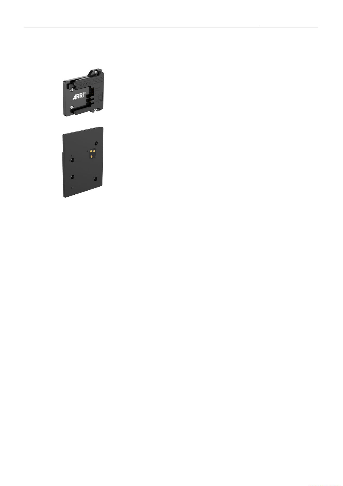
ALEXA 35 Accessories 113
24.4 Battery Adapters
B-Mount Battery Adapter K2.0023751
The B-Mount Battery Adapter attaches into the recessed area at the back of the camera,
the Power Distribution Module PDM-1 or the Audio Extension Module AEM-1 and pro-
vides compatibility with any B-Mount battery.
Battery Adapter Back BAB-LF K2.0034204
The Battery Adapter Back BAB-LF attaches into the recessed area at the back of the
ALEXA 35, the Power Distribution Module PDM-1 or the Audio Extension Module AEM-1
and offers an interface to alternative on-board battery systems originally intended to use
with the ARRI ALEXA LF.
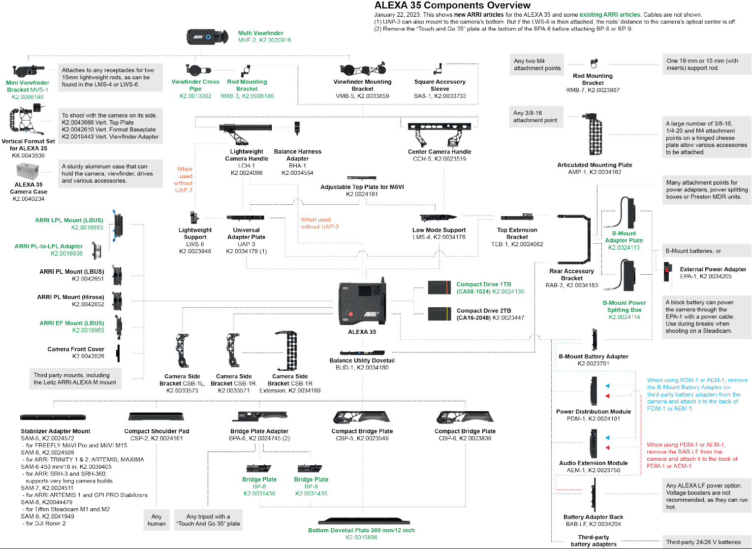

Appendix 115
25 Appendix
25.1 Data Rates, Recording Times and Max. FPS
Rec Time @
24fps (hh:mm)
Max. FPS
Sensor Mode Recording Resolution Data Rate @ 24 fps (incl. audio)
1 TB 2 TB 1 TB 2 TB
2.009 GB/h (ARRIRAW) 00:28 00:56 35 fps 75 fps
4.6K 3:2
Open Gate
4.6K (4608 x 3164)
633 GB/h (Apple ProRes 422 HQ)
945 GB/h (Apple ProRes 4444)
1.414 GB/h (Apple ProRes 4444 XQ)
01:30
01:00
00:40
03:01
02:01
01:21
60 fps 60 fps
4.6K (4608 x 2592) 1.648 GB/h (ARRIRAW) 00:34 01:08 45 fps 75 fps
4.6K 16:9
4K (4096 x 2304)
413 GB/h (Apple 422 HQ)
615 GB/h (Apple 4444)
918 GB/h (Apple 4444 XQ)
02:19
01:33
01:02
04:39
03:07
02:05
75 fps 75 fps
1.304 GB/h (ARRIRAW) 00:43 01:26 55 fps 120 fps
4K (4096 x 2304)
413 GB/h (Apple 422 HQ)
615 GB/h (Apple 4444)
918 GB/h (Apple 4444 XQ)
02:19
01:33
01:02
04:39
03:07
02:05
100 fps
100 fps
90 fps
100 fps
UHD (3840 x 2160)
413 GB/h (Apple 422 HQ)
615 GB/h (Apple 4444)
918 GB/h (Apple 4444 XQ)
02:38
01:46
01:11
05:16
03:32
02:22
120 fps
120 fps
105 fps
120 fps
2K (2048 x 1152)
413 GB/h (Apple 422 HQ)
615 GB/h (Apple 4444)
918 GB/h (Apple 4444 XQ)
08:46
06:00
04:04
17:33
12:01
08:08
120 fps 120 fps
4K 16:9
HD (1920 x 1080)
413 GB/h (Apple 422 HQ)
615 GB/h (Apple 4444)
918 GB/h (Apple 4444 XQ)
09:53
06:47
04:36
19:47
13:34
09:13
120 fps 120 fps
1.160 GB/h (ARRIRAW) 00:48 01:37 65 fps 120 fps
4K 2:1 4K (4096 x 2048)
368 GB/h (Apple 422 HQ)
547 GB/h (Apple 4444)
817 GB/h (Apple 4444 XQ)
02:36
01:45
01:10
05:13
03:30
02:20
120 fps
120 fps
100 fps
120 fps
3.8K 16:9 UHD (3840 x 2160) 1.144 GB/h (ARRIRAW) 00:49 01:38 65 fps 120 fps
1.283 GB/h (ARRIRAW) 00:44 01:28 55 fps 100 fps
3.3K (3328 x 2790)
406 GB/h (Apple 422 HQ)
605 GB/h (Apple 4444)
904 GB/h (Apple 4444 XQ)
02:21
01:35
01:03
04:43
03:10
02:07
75 fps 75 fps
3.3K 6:5
4K 2.39:1 Ana 2x
310 GB/h (Apple 422 HQ)
460 GB/h (Apple 4444)
686 GB/h (Apple 4444 XQ)
03:06
02:05
01:23
06:12
04:10
02:47
90 fps 90 fps

Appendix 116
Rec Time @
24fps (hh:mm)
Max. FPS
Sensor Mode Recording Resolution Data Rate @ 24 fps (incl. audio)
1 TB 2 TB 1 TB 2 TB
1.304 GB/h (ARRIRAW) 00:43 01:26 55 fps 100 fps
3K (3072 x 3072)
413 GB/h (Apple 422 HQ)
615 GB/h (Apple 4444)
918 GB/h (Apple 4444 XQ)
02:19
01:33
01:02
04:39
03:07
02:05
90 fps 90 fps
3K 1:1
3.8K 2:1 Ana 2x
324 GB/h (Apple 422 HQ)
482 GB/h (Apple 4444)
719 GB/h (Apple 4444 XQ)
02:57
01:59
01:20
05:55
03:59
02:40
100 fps 100 fps
2.7K 8:9 UHD 16:9 Ana 2x
364 GB/h (Apple 422 HQ)
541 GB/h (Apple 4444)
808 GB/h (Apple 4444 XQ)
02:38
01:46
01:11
05:16
03:32
02:22
100 fps 100 fps
2K 16:9 S16 2K (2048 x 1152)
109 GB/h (Apple 422 HQ)
160 GB/h (Apple 4444)
236 GB/h (Apple 4444 XQ)
08:46
06:00
04:04
17:32
12:01
08:08
120 fps 120 fps

Appendix 117
25.2 Sensor Related Information
Single Frame Spots of Various Shape – also known as “Digital Dust” or “White Flecks”
Natural and/or artificial radiation may cause a “false exposure” on the image sensor. The shape of
these spots may vary from dots to lines or other, sometimes irregular shapes. These spots occur in
random locations of the image, last only for a single frame and are more visible in dark images. This is
a principle issue of all image sensors and not a malfunction.
Flicker
Some light sources (i.e. discharge tubes or LEDs) may cause an interference with sensor exposure.
This may result in image flickering or “bands” of different brightness moving up or down the image.
Please note that at higher frame rates (100 fps in 50Hz countries, 120 fps in 60Hz countries) even
tungsten light may flicker. A short recording and playback will show this flicker.
Rolling Shutter
Due to the rolling shutter design principle of the sensor the following effects can be observed in certain
situations:
Skewed/slanted vertical lines: fast panning or fast-moving objects may result in vertical structures
to appear “skewed/slanted”. The intensity of the effect depends on the relative speed of panning/
object.
Partial exposure: very short light effects (i.e. a photographer’s flash or strobe light) may result in the
upper part of the image showing the light effect whereas the lower part does not or vice versa.
“Black Sun”
Very bright lights (i.e. the sun, or a photographer’s flash) may result in a black/magenta spot.
Stuck Pixels at Long Exposure Times
At longer exposure times (longer than the standard 1/50
th
of a second), stuck pixels may become visible
in darker image areas. The longer the exposure time the more pixels will be affected. When using
exposure times longer than 1/24
th
of a second, carefully check your image whether the quality meets
your requirements.
25.3 Companion Tools
ARRI maintains various tools to support your work with the ALEXA 35 on- and off-set.
ARRI Reference Tool
The ARRI Reference Tool (ART) combines the functionality of the ARRIRAW Converter, ARRI Color
Tool, and ARRI Meta Extract. It supports all ALEXA 35 recording formats and allows the creation of
ALF4 look files, conversion to SDR and HDR color spaces with looks applied, and export to Apple
ProRes, OpenEXR and TIFF files.
► ARRI Reference Tool
Camera Simulators
The camera simulator is an interactive learning tool to familiarize yourself with the menu navigation of
ARRI digital cameras. Get started now and learn first hand the simple, straightforward menu system
that only ARRI digital cameras offer.
► Camera Simulators

Appendix 118
Formats and Data Rate Calculator
The ARRI Formats and Data Rate Calculator (FDRC) is an online tool that calculates the record
durations and data rates for different camera settings (combinations of camera model, codec,
resolution, project rate, sensor speed, recording media, audio on/off). It also gives deeper insight into
available recording formats and camera modes.
► Formats & Data Rate Calculator
Frame Line & Lens Illumination Tool
The Frame Line & Lens Illumination Tool can be used for creating custom frame lines for ARRI cameras
and for checking how different lenses illuminate different ARRI sensor sizes, recording formats, target
aspect ratios and framelines.
► Frame Line & Lens Illumination Tool
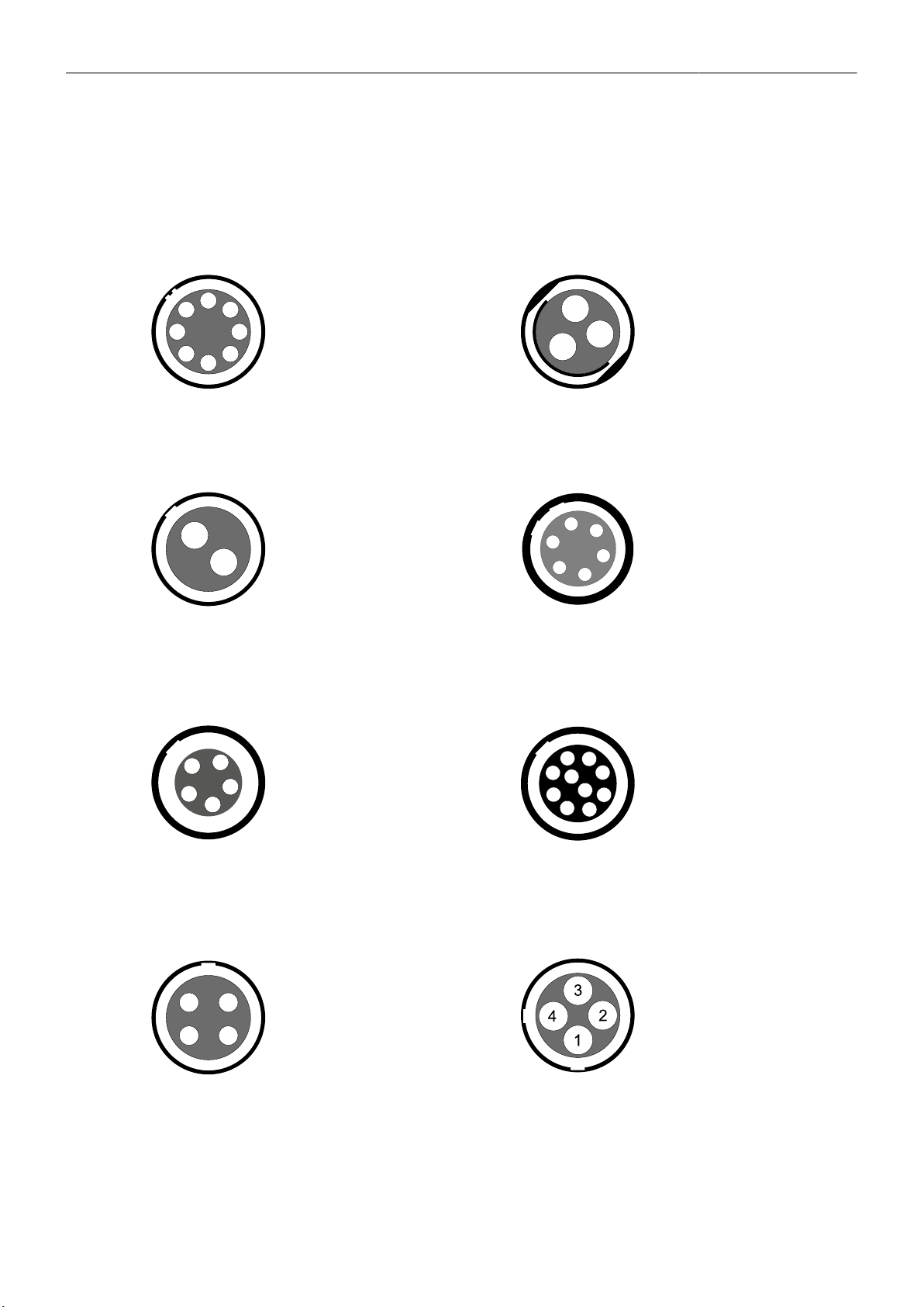
Appendix 119
25.4 Connector Pin-Outs
All pin-outs appear as seen by the user.
PWR (LEMO EEJ.2B.308) RS (Fischer DBP102A052-130)
1
2
3
4
5
6
7
8
1 Batcom
2 Power GND
3 Power GND
4 Power GND
5 Batcom GND
6 Batplus
7 Batplus
8 Batplus
1
3
2
1 GND
2 24 V Aux
3 R/S
12V (LEMO EEG.0B.302.CLN.A365) AUDIO (LEMO EEA.0B.306.CLN)
1
2
1 GND
2 12 V Aux
2
3
4
5
6
1
1 GND
2 CH 1 (+)
3 CH 1 (-)
4 CH 2 (+)
5 CH 2 (-)
6 12 V
TC (LEMO EEG.0B.305) ETH (LEMO EEG.1B.310)
2
4
3
1
5
1 GND
2 LTC In
3 Aux
4 Aux
5 LTC Out
2
3
1
6
7
4
5
8
9
10
1 MX-1P (white-orange)
2 MX-1N (orange)
3 MX-2P (white-green)
4 MX-2N (green)
5 MX-3P (blue)
6 MX-3N (white-blue)
7 MX-4P (white-brown)
8 MX-4N (brown)
9 GND
10 Proprietary - do not use
LBUS (LEMO EEG.0B.304) SERIAL (LEMO EEC.0B.304.CLN)
1 4
2 3
1 GND
2 Can L
3 VBat
4 Can H
1 RX/B
2 12 V
3 TX/A
4 GND

Appendix 120
Ethernet (RJ45) Headphones Out (on MVF-2)
4
2
TIP
3
RING
1
GND
GND
1 GND
2 GND
3 R Out
4 L Out
Audio Cable K2.0023988
ARRI offers an ALEXA Mini LF / ALEXA 35 audio cable with a matching connector to create audio
adapters. The following table shows the wire assignments of this cable.
Wire Function
Black
Blue
Brown
Yellow
Green
Red
GND
CH 1 (+)
CH 1 (-)
CH 2 (+)
CH 2 (-)
12 V
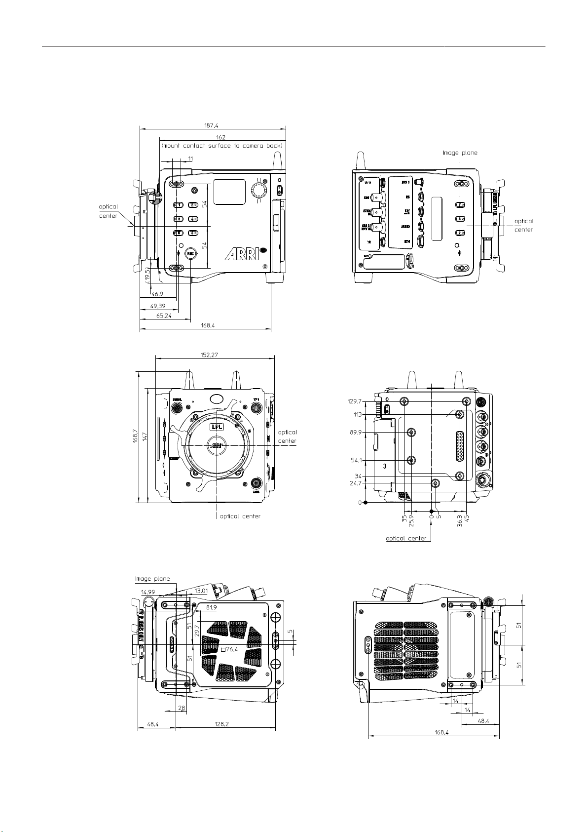
Appendix 121
25.5 Dimensional Drawings
ALEXA 35 with LPL Mount (LBUS). All measurements in mm.

122