
USER MANUAL
MANUALE D’USO
BM 2006
- ZM 2000 system desk-top
paging microphone
- Base microfonica da tavolo
per il sistema ZM 2000

2
TABLE OF CONTENTS
INDICE
ENGLISH
SAFETY PRECAUTIONS
DESCRIPTION
INSTALLATION
SETTINGS
USE
SPECIFICATIONS
ITALIANO
AVVERTENZE PER LA SICUREZZA
DESCRIZIONE
INSTALLAZIONE
IMPOSTAZIONI
UTILIZZO
DATI TECNICI
3
4
7
8
11
12
13
14
17
18
21
22

3
ENGLISH
SAFETY PRECAUTIONS
IMPORTANT NOTES
SAFETY PRECAUTIONS
IMPORTANT NOTES
Before connecting and using this paging microphone, please read this instruction
manual carefully and keep it on hand for future reference. The manual is to be
considered an integral part of this product and must accompany it when changing
ownership as a reference for correct installation and use as well as for the safety
precautions.
RCF S.p.A. will not assume any responsibility for the incorrect installation and / or use
of this product.
SAFETY PRECAUTIONS
1. All the precautions, in particular the safety ones, must be read with special attention,
as they provide important information.
2. Make sure all connections have been made correctly before switching all devices on.
Do not connect / disconnect the paging microphone when the system is operating.
3. Protect paging microphone cables from damage and assure they are positioned
where these cannot be stepped on or crushed by objects.
4. Do not put the paging microphone into water (or another liquid), do not throw it.
5. Never attempt to carry out any operations, modications or repairs.
If the paging microphone does not work properly, contact your authorized service centre.
6. Should the paging microphone emit any strange odour or even smoke, turn the sound
system off immediately and disconnect it.
7. RCF S.p.A. strongly recommends the sound system installation is only made by
professional qualied installers (or specialised rms), who can certify it according to the
regulations in force.
The entire audio system must comply with the current standards and regulations
regarding electrical systems.
8. Mechanical and electrical factors need to be considered when installing a professional
audio system (in addition to those which are strictly acoustic, such as sound pressure,
angles of coverage, frequency response, etc.).
9. Do not point the microphone at near loudspeakers, in order to avoid feedback.
10. Hearing loss
Exposure to high sound levels can cause permanent hearing loss. The acoustic pressure
level that leads to hearing loss is different from person to person and depends on the
duration of exposure.
To prevent potentially dangerous exposure to high levels of acoustic pressure, anyone
who is exposed to these levels should use adequate protection devices.
When a transducer capable of producing high sound levels is being used, it is therefore
necessary to wear ear plugs or protective earphones.
11. To prevent inductive effects from causing hum, noise and a bad system operating,
paging microphone cables should not be laid together with other electric cables (mains)
and loudspeaker lines.
12. Keep the paging microphone far from any excessive heat source.
13. Do not use solvents, alcohol, benzene or other volatile substances for cleaning the
external parts. Just use a dry cloth.

4
ENGLISH
RCF S.P.A. THANKS YOU FOR PURCHASING THIS PRODUCT, WHICH
HAS BEEN DESIGNED TO GUARANTEE RELIABILITY AND HIGH
PERFORMANCES.
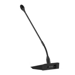
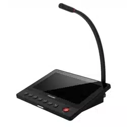
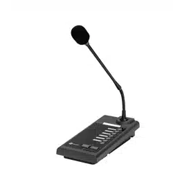
BM 2006 are 6-zone paging microphones designed for the ZM 2000 system.
Up to six BM 2006 can be daisy-chained to a ZM 2124 / ZM 2100 main unit.
It is possible to link up to four BE 2012 additional 12-zone keyboards to every BM
2006, in order to reach the maximum system capability of 54 zones when one ore
more ZE 2200 expanders are used.
MAIN FEATURES:
- 6 zone / zone group buttons
- ‘All Call’ button
- ‘PTT’ button (momentary microphone activation for short announcements)
- ‘Lock’ button (as ‘PTT’, but operating as a toggle for long announcements)
- Flexible gooseneck with an electret microphone capsule
- Balanced input / output on RJ 45 ports (CAT 5 cable)
- Priority mode setting.
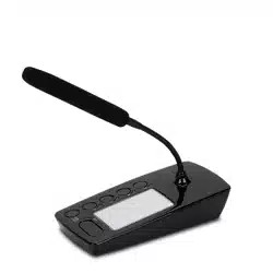
DESCRIPTION
MAIN FEATURES
5
ENGLISH
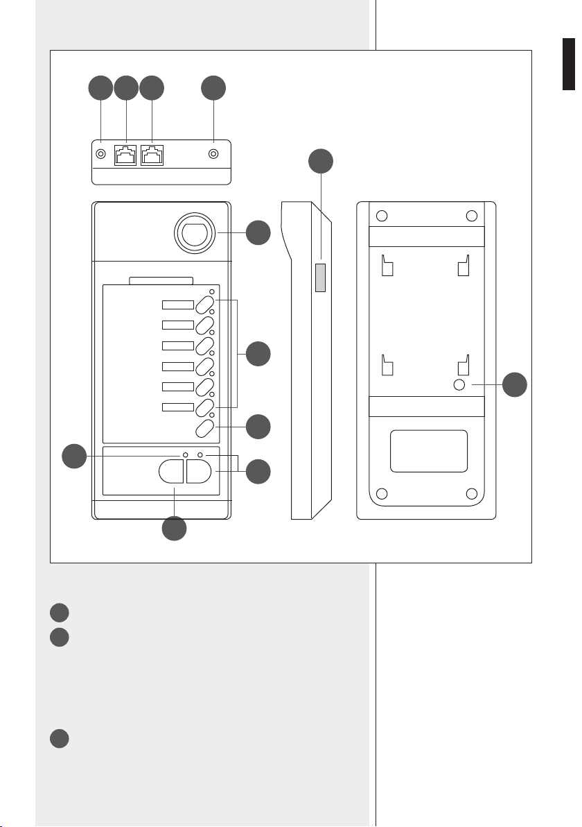
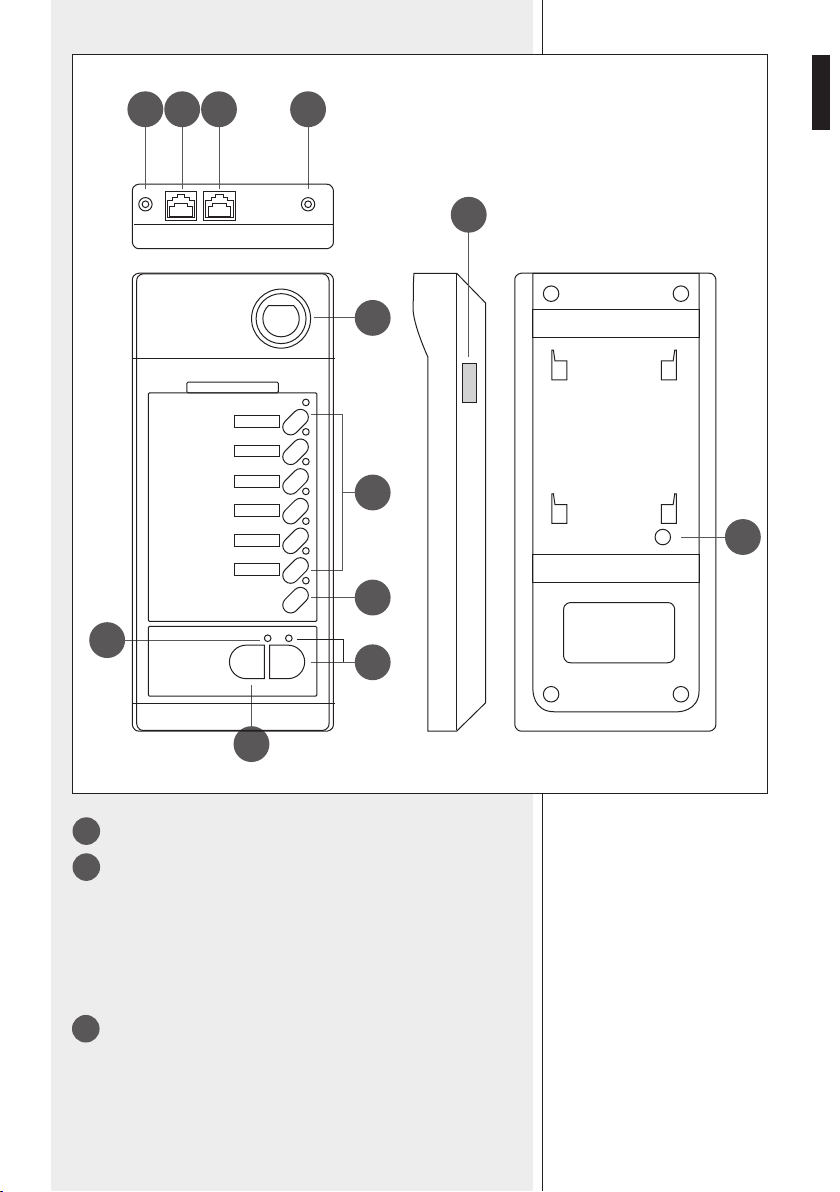
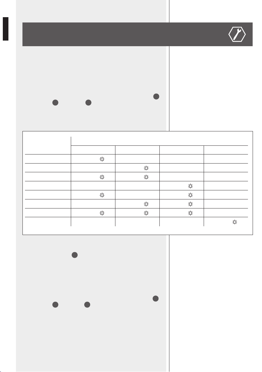
1
Gooseneck with electret microphone.
2
Six zone buttons with LEDs.
Press one or more buttons to select and engage the zones to be paged.
LEDs (when lit) indicate which zones are selected for paging.
To select a zone group (if previously set, see page 11 'ZONE GROUPS'),
press and hold the chosen button for at least 3 seconds.
The selected zone will be activated when pressing either the PTT or the
TALK button.
3
ALL CALL button with LED
Press the ‘All Call’ button to select all zones (its respective LED lights up).
All zones will be activated when pressing either the PTT or the TALK
button (all zone LEDs light up).
7
9 8
1
4
3
12
5
2
1011
6
REAR
TOP RIGHT BOTTOM

6
ENGLISH
4
PTT button (push-button to be held, mainly indicated for short
announcements)
Select zones, then press and hold the PTT button to talk.
If no other paging microphone with higher priority engages the line (or
the EMERGENCY is in progress), the chime will be played and then the
microphone will get open.
In case of any event in progress with higher priority (the TALK LED
5
will be ashing after pressing the PTT button),
it will not be possible to
page the selected zones until the line is not busy.
After the announcement, release the PTT button; all selected zone LEDs
light off.
If no zone has been selected, press and hold the PTT button to page
(again) the same zone / group selected in the previous call.
5
TALK LED
LED steady lit (green): the microphone is open.
LED ashing (amber): the line is busy.
6
LOCK button (toggle switch) with LED
Select zones, then press the LOCK button to talk.
If no other paging microphone with higher priority engages the line (or
the EMERGENCY is in progress), the chime will be played and then the
microphone will get open.
In case of any event in progress with higher priority (the TALK LED
5
will be ashing after pressing the PTT button),
it will not be possible to
page the selected zones until the line is not busy.
After the announcement, press the LOCK button again; all selected
zone LEDs light off.
7
Connector to link the rst BE 2012 additional keyboard.
8
Output level trimmer
If necessary, use a small screw driver to adjust the paging microphone
output level.
9
Input (RJ 45 port)
Port to link the next BM 2006 paging microphone (through CAT5
cable).
The system can have max. six BM 2006 paging microphones.
10
Output (RJ 45 port)
Port to link either the previous BM 2006 paging microphone or the ZM
2124 / ZM 2100 main unit (through CAT5 cable).
11
DC power supply input
Jack socket for the connection of an optional 24 V dc adapter.
12
Chime level control
If necessary, use a small screw driver to adjust the chime level.
7
ENGLISH
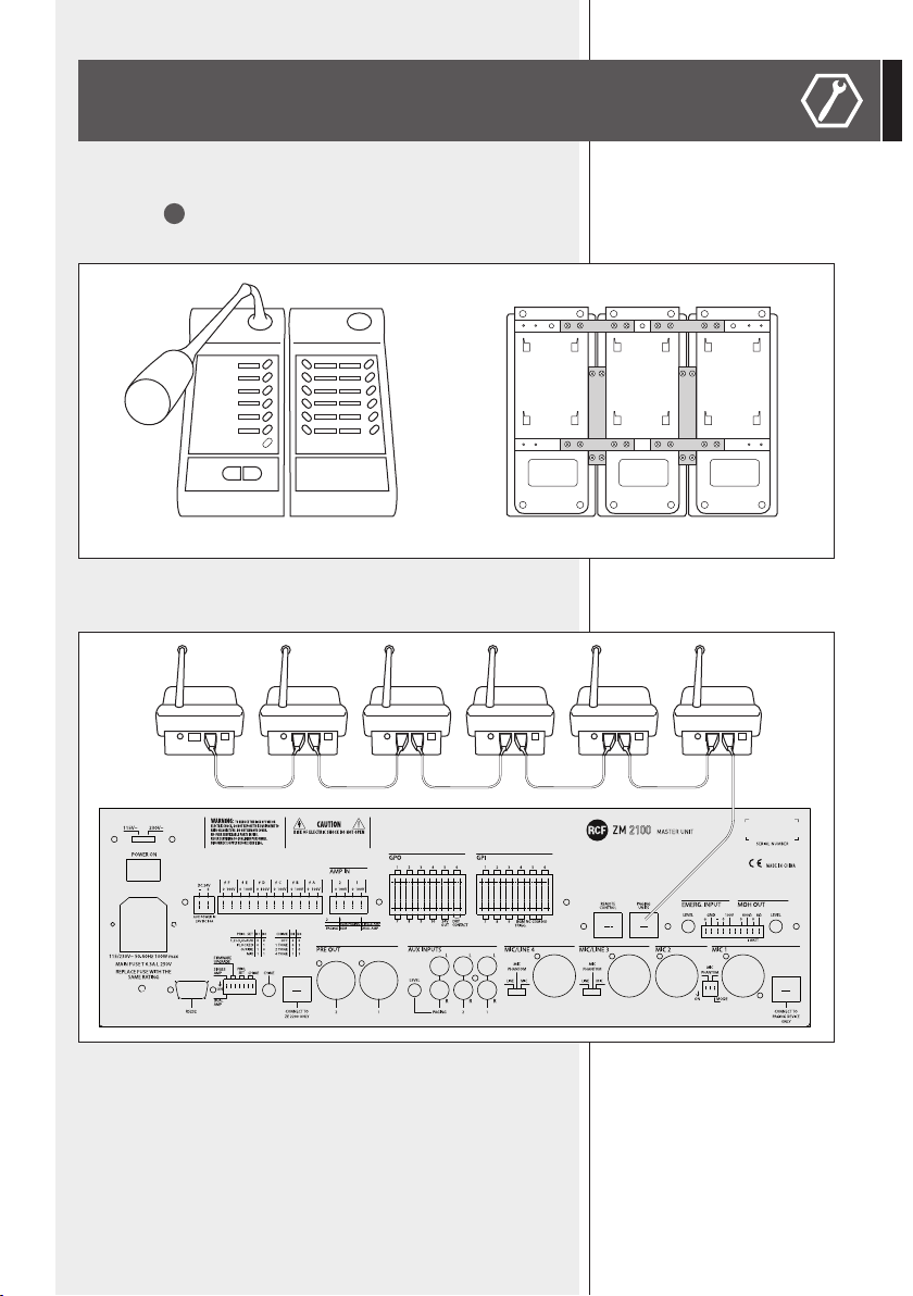
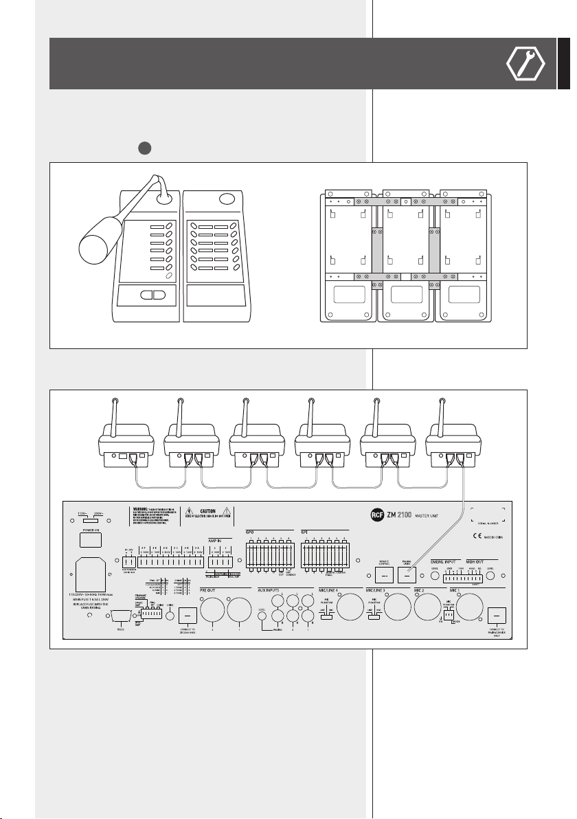
INSTALLATION
If available, link all BE 2012 additional 12-zone keyboards (max. 4 per each
BM 2006), by connecting all at cables (see the BE 2012 manual) to the
lateral ports (
7
on BM 2006).
Use metal brackets to x BE 2012 keyboards.
Connect all BM 2006 paging microphones (daisy-chained through CAT5
cable), as according to the following gure:
The rst BM 2006 needs to be linked to the ZM 2124 / ZM 2100 PAGING
UNITS port.
When using long cables or additional BE 2012 keyboards, it is necessary to
connect additional 24 V dc adapters to BM 2006 paging microphones.
Turn the system on and set all paging microphones (see the next ‘Settings’
manual section).
SERIGRAFIA PANNELLO POSTERIORE
REAR PANEL SILK-SCREEN
VEDI NOTE
VEDI NOTE / SEE NOTES
VEDI NOTE / SEE NOTES
SEE NOTES
PL010627
ZM 2100
CANOVI
A EMISSIONE DOCUMENTO / FIRST RELEASE
1
1
CANOVI TAMAGNINI
13/12/2011
B MODIFICATA INDICAZIONE AMPLI INTERNO / MODIFIED INTERNAL AMPLIFIER INDICATION
CANOVI
27/06/2012
27/06/2012
A B
1:1
CONTR.
CHECK
CONTR.
CHECK
DISEGN.
DRAWN
DISEGN.
DRAWN
DATA
DAT E
DATA
DAT E
CODICE / PART NUMBER
MATRICOLA
SCALA / SCALE
UNI EN 22768-1
GRADO DI PRECISIONE / ACCURACY
QUOTE SENZA INDICAZIONE DI TOLLERANZA.
DIMENSIONS WITHOUT TOLLERANCE INDICATIONS.
EN 22768-1
FOGLIO / SHEET
N. OGGETTO MODIFICA / MODIFY OBJECT
DESCRIZIONE
DESCRIPTION
MATERIALE
MATERIAL
TRATT. TERMICO
HEAT TREATMENT
TRATT. SUPERFICIALE
SURFACE TREATMENT
A TERMINE DI LEGGE CI RISERVIAMO LA PROPRIETÀ DI QUESTO DISEGNO CON DIVIETO DI RIPRODUZIONE E RENDERLO NOTO A TERZI SENZA NOSTRA AUTORIZZAZIONE SCRITTA
FOGLI / SHEETS
VALIDO SOLO PER RIFERIMENTO
FOR REFERENCE ONLY
NOTE:
- Dimensioni Meccaniche
NOTES:
- Mechanical Dimension
NOTE:
- Serigrafare colore COOL-GREY 1
- Fondo: Colore Nero opaco RAL 9005
NOTES:
- Silk-screen printing color
COOL-GREY 1
- Background: Color Black matt RAL 9005
8
ENGLISH
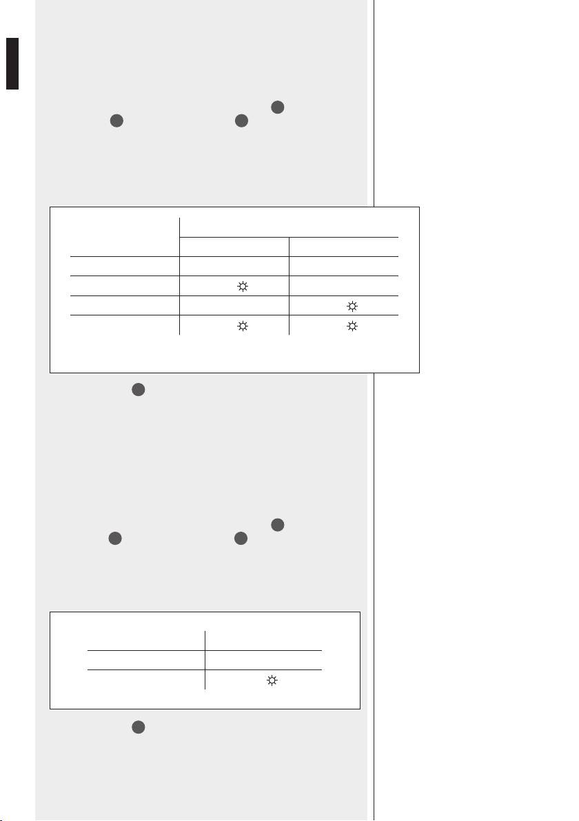
ID ADDRESS
ZONE LEDs
Zone 1 Zone 2 Zone 3 Zone 4
1
ON
2
ON
3
ON
ON
4
ON
5
ON
ON
6
ON
ON
7 *
ON
ON ON
8 *
ON
IP ADDRESS
Each BM 2006 paging microphone needs to be set to its unique digital
address (there cannot be two or more BM 2006 having the same ID number).
1. Press and hold (at least 3 seconds) both the PTT
4
and zone 6
buttons
2
, then both the TALK LED
5
and the zone 6 LED will
ash.
2
. Press the zone 6 button to get the sequential change of the ID
address according to the following table:
SETTINGS
* ID addresses 7 and 8 are currently not used.
3. Press the PTT
4
button to exit.
MIC SENSITIVITY
It is possible to adjust the microphone sensitivity
.
1. Press and hold (at least 3 seconds) both the PTT
4
and zone 5
buttons
2
, then both the TALK LED
5
and the zone 5 LED will ash.
2. Press the
zone 5 button to get the sequential change (6 steps) of the
microphone sensitivity according to the following table:
IP ADDRESS
MIC SENSITIVITY
9
ENGLISH
MIC
SENSITIVITY
ZONE LEDs
Zone 1 Zone 2 Zone 3
Minimum
ON
ON
ON ON
ON
ON ON
Maximum
ON
ON
3. Press the PTT
4
button to exit.
PRIORITY
T
he priority mode can be chosen among 4 different options.
1. Press and hold (at least 3 seconds) both the PTT
4
and zone 4
buttons
2
, then both the TALK LED
5
and the zone 4 LED will
ash.
2. Press the
zone 4 button to get the sequential change of priority mode
according to the following table:
PRIORITY MODE
ZONE LEDs
Zone 1 Zone 2 Zone 3
Graduated: paging mic.
1 > 2, 2 > 3, 3 > 4
ON
Paging microphones work on a
rst-come-rst-served basis
ON
A new announcement overrides
the previous still in progress
ON
ON
All paging microphones have the
same priority level
ON
3. Press the PTT
4
button to exit.
PRIORITY
10
ENGLISH
CHIME MODE
ZONE LEDs
Zone 1 Zone 2
OFF
CHIME 1
ON
CHIME 2
ON
CHIME 3
ON
ON
CHIME
Chime tone setting.
1. Press and hold (at least 3 seconds) both the PTT
4
and zone 3
buttons
2
, then both the TALK LED
5
and the zone 3 LED will
ash.
2.
1.Press the zone 3 button to get the sequential change of the chime
mode according to the following table:
3. Press the PTT
4
button to exit.
3. Press the
PTT
4
button to exit.
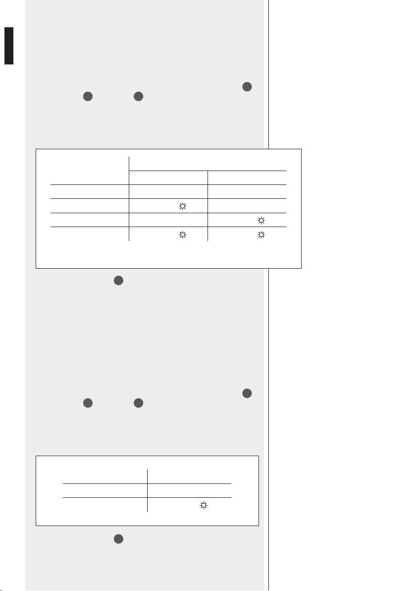
SPEECH FIL
TER
It is possible to set on/off the microphone high-pass lter (cutoff frequency:
315 Hz, slope: 6 dB / octave). The high-pass lter may help increase the
speech intelligibility in acoustically critical areas (for instance, due to long
reverberation time).
1. Press and hold (at least 3 seconds) both the PTT
4
and zone 2
buttons
2
, then both the TALK LED
5
and the zone 2 LED will
ash.
2. Press the
zone 2 button to turn on/off the speech lter:
SPEECH FILTER ZONE 1 LED
ON
OFF
ON
CHIME
SPEECH FILTER
11
ENGLISH
ZONE GROUPS
1. Press and hold (at least 3 seconds) both the PTT
4
and zone 1
buttons
2
, then all zone LEDs will flash.
2. Select (press) a zone button where to store the group.
3.
While all LEDs are ashing, select the zones to be added to the group
by pressing their respective buttons (in each selected zone, the LED is
now steady lit).
4. Press the PTT
4
button to conrm and exit.
USE
1. Before turning the system on, connect all BM 2006 paging
microphones and BE 2012 keyboards (if available) according to the
‘Installation’ manual section.
2. Turn the system on and (for every BM 2006 paging microphone) set the
proper IP address, mic sensitivity, priority, chime, speech lter and zone
groups.
3.
Select zones to be paged; all selected zone LEDs light up.
To select a zone group, press and hold the chosen zone button for at
least 3 seconds.
4. Press and hold the PTT button
4
or press the LOCK button
6
to talk.
If no other paging microphone with higher priority engages the line (or
the EMERGENCY is in progress), the chime will be played and then the
microphone will get open.
In case of any event in progress with higher priority, it will not be
possible to page the selected zones until the line is not busy.
TALK LED
5
steady lit (green): the microphone is open.
TALK LED
5
ashing (amber): the line is busy.
5. After the announcement, release the PTT button (if held) or press the
LOCK button again; all selected zone LEDs light off.
CHIME
SPEECH FILTER
ZONE GROUPS
It is possible to store some zones to a group, which can be assigned to a
single BM 2006 button (max. 6 groups, it is not possible to store zone
groups to BE 2012 buttons).

12
ENGLISH
Operating voltage
Max. current draw
Max. audio output level
Frequency response
Speech lter
Dimensions (w, h, d)
Net weight
24 V dc
50 mA (BM 2006 only)
130 mA (with a single BE 2012 keyboard)
210 mA (with two BE 2012 keyboards)
290 mA (with three BE 2012 keyboards)
370 mA (with four BE 2012 keyboards)
1 V (RMS)
100 Hz ÷ 15 kHz
high-pass, cutoff: 315 Hz, slope: 6 dB /
octave
108 mm, 55 mm, 240 mm (BM 2006 only)
1 kg (BM 2006 only)
SPECIFICATIONS

13
ITALIANO
AVVERTENZE PER
LA SICUREZZA
IMPORTANTE
IMPORTANTE
Prima di collegare ed utilizzare la base microfonica, leggere attentamente le istruzioni
contenute in questo manuale, il quale è da conservare per riferimenti futuri.
Il presente manuale costituisce parte integrante del prodotto e deve accompagnare
quest’ultimo anche nei passaggi di proprietà, per permettere al nuovo proprietario di
conoscere le modalità d’installazione e d’utilizzo e le avvertenze per la sicurezza.
L’installazione e l’utilizzo errati del prodotto esimono RCF S.p.A. da ogni responsabilità.
AVVERTENZE PER LA SICUREZZA
1. Tutte le avvertenze, in particolare quelle relative alla sicurezza, devono essere lette
con particolare attenzione, in quanto contengono importanti informazioni.
2. Prima di accendere le apparecchiature, assicurarsi che tutte le connessioni siano
corrette.
Non collegare / scollegare la base microfonica quando il sistema è acceso.
3. Accertarsi che il cavo della base microfonica non possa essere calpestato o
schiacciato da oggetti, al ne di salvaguardarne l’integrità.
4. Non immergere la base microfonica nell’acqua (od in altri liquidi), non lanciarla o
lasciarla cadere.
5. Non eseguire sulla base microfonica interventi / modiche / riparazioni; contattare i
centri di assistenza autorizzati nel caso che non funzioni correttamente.
6. Nel caso che dalla base microfonica provengano stranamente odori anomali od
addirittura fumo, spegnere immediatamente il sistema audio e scollegarla.
7. RCF S.p.A. raccomanda vivamente che l’installazione del sistema audio sia eseguita
solamente da installatori professionali qualicati (oppure da ditte specializzate) in grado
di farla correttamente e certicarla in accordo con le normative vigenti. Tutto il sistema
audio dovrà essere in conformità con le norme e le leggi vigenti in materia di impianti
elettrici.
8. I fattori meccanici ed elettrici sono da considerare quando si installa un sistema audio
professionale (oltre a quelli prettamente acustici, come la pressione sonora, gli angoli di
copertura, la risposta in frequenza, ecc.).
9. Non puntare la base microfonica verso un diffusore acustico vicino, onde evitare un
possibile innesco.
10. Perdita dell’udito
L’esposizione ad elevati livelli sonori può provocare la perdita permanente dell’udito.
Il livello di pressione acustica pericolosa per l’udito varia sensibilmente da persona
a persona e dipende dalla durata dell’esposizione. Per evitare un’esposizione
potenzialmente pericolosa ad elevati livelli di pressione acustica, è necessario che
chiunque sia sottoposto a tali livelli utilizzi delle adeguate protezioni; quando si
fa funzionare un trasduttore in grado di produrre elevati livelli sonori è necessario
indossare dei tappi per orecchie o delle cufe protettive.
11. Per evitare che fenomeni induttivi diano luogo a ronzii, disturbi e compromettano
il buon funzionamento dell’impianto, il cavo della base microfonica non deve essere
canalizzato insieme ai conduttori dell’energia elettrica e/o alle linee dei diffusori acustici.
12. Collocare la base microfonica lontano da amme (o fonti di calore eccessivo).
13. Non usare solventi, alcool, benzina o altre sostanze volatili per la pulitura delle parti
esterne; usare un panno asciutto.

14
ITALIANO
RCF S.P.A. VI RINGRAZIA PER L’ACQUISTO DI QUESTO PRODOTTO,
REALIZZATO IN MODO DA GARANTIRNE L’AFFIDABILITÀ E
PRESTAZIONI ELEVATE.
BM 2006 è una base microfonica dedicata per il sistema ZM 2000 che permette
di effettuare annunci selettivi su 6 zone. Si possono collegare in cascata (sulla
stessa linea ad un’unità centrale ZM 2124 / ZM 2100) no a 6 basi microfoniche
BM 2006.
È possibile collegare no a 4 tastiere BE 2012 addizionali (ciascuna avente 12
tasti zona) ad ogni BM 2006, in modo da gestire no a (max.) 54 zone quando
sono utilizzate una o più unità di espansione ZE 2200.
CARATTERISTICHE PRINCIPALI:
- 6 tasti per selezione zone / gruppi di zone;
- tasto per la chiamata generale su tutte le zone;
- tasto PTT (da tener premuto) per l’attivazione del microfono (per brevi
annunci);
- tasto LOCK utilizzabile come interruttore acceso/spento del microfono (più
indicato del tasto PTT per annunci di media / lunga durata);
- capsula microfonica ad elettrete su braccio essibile;
- ingresso / uscita audio bilanciati su porta RJ 45 (cavo CAT 5)
- impostazione della modalità di priorità.
DESCRIZIONE
CARATTERISTICHE
PRINCIPALI
15
ITALIANO
1
Braccio essibile con capsula microfonica ad elettrete.
2
Sei tasti per la selezione delle zone con rispettivi indicatori a LED.
Premere uno o più tasti per selezionare ed occupare le zone da
chiamare. I LED (quando accesi) indicano quali zone sono
selezionate per l'annuncio; le zone selezionate si attivano non
appena è premuto il tasto PTT o TALK.
Per selezionare un gruppo di zone (se impostato in precedenza,
vedere "GRUPPI DI ZONE" a pagina 21), premere e tener premuto
per almeno 3 secondi il tasto scelto.
3
Tasto ALL CALL (con LED) per la selezione di tutte le zone
Premere il tasto ALL CALL per selezionare tutte le zone (il rispettivo LED
s'illumina).
Tutte le zone saranno attivate non appena sarà premuto il tasto PTT o
TALK (tutti i LED delle zone si accendono).
7
8
1
4
3
12
5
2
6
RETRO
FRONTE FIANCO DESTRO FONDO
9 1011

16
ITALIANO
4
Tasto PTT (pulsante non ritenuto, indicato per annunci brevi)
Selezionare le zone, poi premere e tener premuto il tasto PTT per attivare
il microfono.
Se la linea non è già impegnata da un'altra base microfonica (o da un
evento di emergenza in corso), il tono di preavviso (“chime”) è riprodotto
e, successivamente, si attiva il microfono.
Nel caso che sia già in corso un evento con priorità più alta (il LED
TALK
5
lampeggia dopo aver premuto il tasto PTT), non è possibile
effettuare annunci verso le zone selezionate no a quando la linea è
impegnata.
Dopo aver terminato l'annuncio
, rilasciare il tasto PTT; tutti i LED delle
zone selezionate si spengono.
Tenendo premuto il tasto PTT per almeno 3 secondi (senza aver
selezionato almeno una zona), si effettua di nuovo un annuncio verso la
zona od il gruppo chiamato precedentemente.
5
LED TALK
LED acceso sso (verde): il microfono è attivato (canale audio aperto).
LED lampeggiante (arancio): la linea è occupata.
6
Tasto LOCK (interruttore bistabile) con LED
Selezionare le zone, poi premere il tasto LOCK per attivare il microfono.
Se la linea non è già impegnata da un'altra base microfonica (o da un
evento di emergenza in corso), il tono di preavviso (“chime”) è riprodotto
e, successivamente, si attiva il microfono.
Nel caso che sia già in corso un evento con priorità più alta (il LED
TALK
5
lampeggia dopo aver premuto il tasto PTT), non è possibile
effettuare annunci verso le zone selezionate no a quando la linea è
impegnata.
Dopo aver terminato l'annuncio
, premere di nuovo il tasto LOCK; tutti i
LED delle zone selezionate si spengono.
7
Connettore per il collegamento della prima tastiera BE 2012 addizionale.
8
Trimmer per la regolazione del livello audio d’uscita
Se necessario, usare un piccolo cacciavite per regolare il livello d’uscita
della base microfonica.
9
Ingresso (porta RJ 45)
Porta per il collegamento della base microfonica BM 2006 successiva
(tramite cavo CAT5).
Il sistema può essere implementato con massimo sei basi microfoniche BM
2006.
10
Uscita (porta RJ 45)
Porta per il collegamento della base microfonica BM 2006 precedente o
dell’unità centrale ZM 2124 / ZM 2100 (tramite cavo CAT5).
11
Ingresso per alimentazione in corrente continua
Connettore per il collegamento di un alimentatore (opzionale) 24 V c.c. .
12
Controllo del livello del tono di preavviso (“chime”)
Se necessario, usare un piccolo cacciavite per regolare il livello del tono
di preavviso (“chime”).
17
ITALIANO
INSTALLAZIONE
Se disponibili, ssare tutte le tastiere addizionali BE 2012 (max. 4 per
ciascuna BM 2006) tramite staffe metalliche e collegare i cavi dedicati (“at
cable”); leggere il manuale BE 2012 per il verso corretto alle rispettive porte
laterali (vedere punto
7
).
Collegare tutte le basi microfoniche BM 2006 (in cascata tramite cavo CAT5)
come mostrato nella gura seguente:
La prima base microfonica BM 2006 deve essere collegata alla porta
PAGING UNITS dell'unità centrale ZM 2124 / ZM 2100.
Quando si utilizzano cavi di lunghezza considerevole o tastiere BE 2012
addizionali, è necessario collegare degli alimentatori 24 V c.c. alle basi
microfoniche BM 2006.
Accendere il sistema ed impostare (una ad una) tutte le basi microfoniche
(vedere la sezione successiva del manuale).
SERIGRAFIA PANNELLO POSTERIORE
REAR PANEL SILK-SCREEN
VEDI NOTE
VEDI NOTE / SEE NOTES
VEDI NOTE / SEE NOTES
SEE NOTES
PL010627
ZM 2100
CANOVI
A EMISSIONE DOCUMENTO / FIRST RELEASE
1
1
CANOVI TAMAGNINI
13/12/2011
B MODIFICATA INDICAZIONE AMPLI INTERNO / MODIFIED INTERNAL AMPLIFIER INDICATION
CANOVI
27/06/2012
27/06/2012
A B
1:1
CONTR.
CHECK
CONTR.
CHECK
DISEGN.
DRAWN
DISEGN.
DRAWN
DATA
DAT E
DATA
DAT E
CODICE / PART NUMBER
MATRICOLA
SCALA / SCALE
UNI EN 22768-1
GRADO DI PRECISIONE / ACCURACY
QUOTE SENZA INDICAZIONE DI TOLLERANZA.
DIMENSIONS WITHOUT TOLLERANCE INDICATIONS.
EN 22768-1
FOGLIO / SHEET
N. OGGETTO MODIFICA / MODIFY OBJECT
DESCRIZIONE
DESCRIPTION
MATERIALE
MATERIAL
TRATT. TERMICO
HEAT TREATMENT
TRATT. SUPERFICIALE
SURFACE TREATMENT
A TERMINE DI LEGGE CI RISERVIAMO LA PROPRIETÀ DI QUESTO DISEGNO CON DIVIETO DI RIPRODUZIONE E RENDERLO NOTO A TERZI SENZA NOSTRA AUTORIZZAZIONE SCRITTA
FOGLI / SHEETS
VALIDO SOLO PER RIFERIMENTO
FOR REFERENCE ONLY
NOTE:
- Dimensioni Meccaniche
NOTES:
- Mechanical Dimension
NOTE:
- Serigrafare colore COOL-GREY 1
- Fondo: Colore Nero opaco RAL 9005
NOTES:
- Silk-screen printing color
COOL-GREY 1
- Background: Color Black matt RAL 9005
18
ITALIANO
INDIRIZZO
DIGITALE
LED DELLE ZONE
Zona 1 Zona 2 Zona 3 Zona 4
1
ACCESO
2
ACCESO
3
ACCESO
ACCESO
4
ACCESO
5
ACCESO
ACCESO
6
ACCESO
ACCESO
7 *
ACCESO
ACCESO ACCESO
8 *
ACCESO
INDIRIZZO DIGITALE (“IP ADDRESS”)
Ogni base microfonica BM 2006 deve avere un suo unico indirizzo digitale
(non possono coesistere sulla stessa linea due o più BM 2006 aventi lo
stesso indirizzo digitale).
1. Premere e tener premuto (almeno 3 secondi) entrambi i tasti PTT
4
e
zona 6
2
; il LED TALK
5
e quello della zona 6 inizieranno a
lampeggiare
.
1. Premere (una o più volte) il tasto della zona 6 per le selezione
(sequenziale) dell’indirizzo digitale secondo la seguente tabella:
IMPOSTAZIONI
* Gli indirizzi 7 e 8 non sono attualmente utilizzati.
3. Premere il tasto PTT
4
per uscire dalla modalità d’impostazione.
SENSIBILIT
À DEL MICROFONO
È possibile impostare la sensibilità del microfono.
1. Premere e tener premuto (almeno 3 secondi) entrambi i tasti PTT
4
e
zona 5
2
; il LED TALK
5
e quello della zona 5 inizieranno a
lampeggiare
.
2. Premere (una o più volte) il tasto della zona 5 per le selezione
(sequenziale) della sensibilità del microfono secondo la seguente tabella:
INDIRIZZO DIGITALE
(“IP ADDRESS”)
SENSIBILITÀ
DEL MICROFONO
19
ITALIANO
SENSIBILITÀ
MICROFONO
LED DELLE ZONE
Zona 1 Zona 2 Zona 3
Minima
ACCESO
ACCESO
ACCESO ACCESO
ACCESO
ACCESO ACCESO
Massima
ACCESO
ACCESO
3. Premere il tasto PTT
4
per uscire dalla modalità d'impostazione.
PRIORIT
À
La funzione della priorità può essere scelta tra 4 differenti modalità.
1. Premere e tener premuto (almeno 3 secondi) entrambi i tasti PTT
4
e
zona 4
2
; il LED TALK
5
e quello della zona 4 inizieranno a
lampeggiare
.
2. Premere (una o più volte) il tasto della zona 4 per le selezione
(sequenziale) della modalità della priorità secondo la seguente tabella:
MODALITÀ DELLA PRIORITÀ
LED DELLE ZONE
Zona 1 Zona 2 Zona 3
Scalare: base microfonica
1 > 2, 2 > 3, 3 > 4
ACCESO
La prima base microfonica che
occupa la linea ha la priorità
ACCESO
Un nuovo annuncio interrompe
quello precedente in corso
ACCESO
ACCESO
Tutte le basi microfoniche hanno
lo stesso livello di priorità
ACCESO
3. Premere il tasto PTT
4
per uscire dalla modalità d'impostazione.
PRIORITÀ
20
ITALIANO
TONO DI PREAVVISO
LED DELLE ZONE
Zona 1 Zona 2
Disattivato
TIPO 1
ACCESO
TIPO 2
ACCESO
TIPO 3
ACCESO
ACCESO
TONO DI PREAVVISO (“CHIME”)
Impostazione del tono di preavviso (“chime”) prima di un annuncio
microfonico.
1. Premere e tener premuto (almeno 3 secondi) entrambi i tasti PTT
4
e
zona 3
2
; il LED TALK
5
e quello della zona 3 inizieranno a
lampeggiare
.
2. Premere (una o più volte) il tasto della zona 3 per le selezione
(sequenziale) del tono di preavviso secondo la seguente tabella:
3. Premere il tasto PTT
4
per uscire dalla modalità d'impostazione.
3. Premere il tasto
PTT
4
per uscire dalla modalità d'impostazione.
FIL
TRO VOCE
È possibile inserire o disinserire un ltro passa-alto sul microfono (frequenza
di taglio: 315 Hz, pendenza: 6 dB / ottava). Il ltro passa-alto può risultare
utile per migliorare l'intelligibilità del parlato in ambienti critici acusticamente
(a causa, ad esempio, di un lungo tempo di riverbero).
1. Premere e tener premuto (almeno 3 secondi) entrambi i tasti PTT
4
e
zona 2
2
; il LED TALK
5
e quello della zona 2 inizieranno a
lampeggiare
.
2. Premere il tasto della zona 2 per inserire o disinserire il ltro voce:
FILTRO VOCE LED ZONA 1
Inserito
Non inserito
ACCESO
TONO DI PREAVVISO
(“CHIME”)
FILTRO VOCE
21
ITALIANO
GRUPPI DI ZONE
1. Premere e tener premuto (almeno 3 secondi) entrambi i tasti PTT
4
e
zona 1
2
; tutti i LED relativi alle zone inizieranno a lampeggiare.
2. Selezionare (premere) un tasto zona dove memorizzare le impostazioni
del gruppo.
3. Mentre tutti i LED stanno lampeggiando, selezionare le zone da
aggiungere al gruppo premendo i rispettivi tasti (i LED sono ora accesi
ssi in ogni zona selezionata).
4. Premere il tasto PTT
4
per uscire dalla modalità d'impostazione.
UTILIZZO
1. Prima di accendere il sistema, collegare tutte le basi microfoniche BM
2006 e le tastiere aggiuntive BE 2012 (se presenti) come indicato nella
sezione del manuale “Installazione”.
2. Accendere il sistema e (per ogni base microfonica BM 2006) impostare
il corretto indirizzo digitale, la sensibilità del microfono, la modalità
della priorità, il tono di preavviso, il ltro voce ed i gruppi delle zone.
3.
Selezionare le zone dove effettuare l'annuncio; tutti i rispettivi LED si
accendono.
Per selezionare un gruppo di zone, premere e tener premuto per
almeno 3 secondi il tasto zona scelto.
4. Premere e tener premuto il tasto PTT
4
o premere il tasto LOCK
6
per effettuare l'annuncio.
Se la linea non è già impegnata da un'altra base microfonica (o da
un evento di emergenza in corso), il tono di preavviso (“chime”) è
riprodotto e, successivamente, si attiva il microfono.
Nel caso che sia già in corso un evento con priorità più alta (il LED
TALK
5
lampeggia dopo aver premuto il tasto PTT), non è possibile
effettuare annunci verso le zone selezionate no a quando la linea è
impegnata.
LED TALK
5
acceso sso (verde): il microfono è aperto.
LED TALK
5
lampeggiante (arancio): la linea è impegnata.
5. Dopo aver terminato l'annuncio, rilasciare il tasto PTT (se tenuto) o
premere di nuovo il tasto LOCK; tutti i LED delle zone selezionate si
spengono.
TONO DI PREAVVISO
(“CHIME”)
FILTRO VOCE
GRUPPI DI ZONE
Si possono creare dei gruppi di zone assegnati as un singolo tasto (di zona)
della (sola) base mic. BM 2006 (max. 6 gruppi; non è possibile abbinare
un gruppo di zone ad un tasto di una tastiera addizionale BE 2012).

22
ITALIANO
Tensione di funzionamento
Max. assorbimento corrente
Max. livello audio d'uscita
Risposta in frequenza
Filtro voce
Dimensioni (l, h, p)
Peso netto
24 V c.c.
50 mA (solo BM 2006)
130 mA (con 1 tastiera BE 2012)
210 mA (con 2 tastiere BE 2012)
290 mA (con 3 tastiere BE 2012)
370 mA (con 4 tastiere BE 2012)
1 V (RMS)
100 Hz ÷ 15 kHz
passa-alto, frequenza di taglio: 315 Hz,
pendenza: 6 dB / ottava
108 mm, 55 mm, 240 mm (solo BM 2006)
1 kg (solo BM 2006)
DATI TECNICI


10307370 revD 2019 / 01
www.rcf.it
RCF S.p.A. Italy
Via Raffaello Sanzio, 13
42124 Reggio Emilia - Italy
Tel +39 0522 274 411
Fax +39 0522 232 428
e-mail: info@rcf.it
Salvo eventuali errori ed omissioni.
RCF S.p.A. si riserva il diritto di apportare modiche senza preavviso.
Except possible errors and omissions.
RCF S.p.A. reserves the right to make modications without prior notice.