20A | 40A
Version 1.1
ROVER ELITE
Maximum Power Point Tracking Solar Charge Controller
01
General Safety Information
Charge Controller Safety
Important Safety Instructions
Please save these instructions.
This manual contains important safety, installation, and operating instructions for the charge
controller. The following symbols are used throughout the manual to indicate potentially
dangerous conditions or important safety information.
There are no serviceable parts for this controller. Do NOT disassemble or attempt to repair
the controller.
Make sure all connections going into and from the controller are tight.
NEVER connect the solar panel array to the controller without a battery. Battery must be
connected first.
Ensure input voltage does not exceed 100 VDC to prevent permanent damage. Use the
Open Circuit Voltage (Voc) to make sure the voltage does not exceed this value when
connecting panels together.
Read all of the instructions and cautions in the manual before beginning the installation.
Do
NOT
allow water to enter the controller.
NOTE
CAUTION
WARNING
Indicates a potentially dangerous condition. Use extreme caution when
performing this task
Indicates a critical procedure for safe and proper operation of the controller
Indicates a procedure or function that is important to the safe and proper
operation of the controller

02
Battery Safety
Use only sealed lead-acid, flooded, gel or lithium batteries which
must be deep cycle.
Explosive battery gases may be present while charging. Be certain there is enough
ventilation to release the gases.
Be careful when working with large lead acid batteries. Wear eye protection and have
fresh water available in case there is contact with the battery acid.
Over-charging and excessive gas precipitation may damage the battery plates and
activate material shedding on them. Too high of an equalizing charge or too long of one
may cause damage. Please carefully review the specific requirements of the battery
used in the system.
Equalization is carried out only for non-sealed / vented/ flooded / wet cell lead acid
batteries.
Do
NOT
equalize VRLA type AGM / Gel / Lithium cell batteries UNLESS permitted by
battery manufacturer.
Default charging parameters in Li mode are programmed for 12.8V Lithium Iron
Phosphate (LFP) Battery only. Before using Rover Elite to charge other types of lithium
battery, set the parameters according to the suggestions from battery manufacturer.
Carefully read battery manuals before operation.
Do
NOT
let the positive (+) and negative (-) terminals of the battery touch each other.
Connect battery terminals to the charge controller BEFORE connecting
the solar panel(s) to the charge controller. NEVER connect solar panels to
charge controller until the battery is connected.
Once equalization is active in the battery charging, it will not exit this stage
unless there is adequate charging current from the solar panel. There
should be NO load on the batteries when in equalization charging stage.
WARNING
Recycle battery when it is replaced.

Table of Contents
03
General Information
Product Overview
Identification of Parts
04
05
05
07
Rover Elite 40A
Dimensions
06
06
Rover Elite 20A
Additional Components
Installation
Connect the Charge Controller
Cable Sizing
Operation
User Interface
LCD indicators
MPPT Technology
08
10
13
14
15
16
18
22
22
23
24
24
24
26
25
24
Change the Parameters
09
15
16
Mount the Charge Controller
Protection Behaviors / Fixes
Error Codes / Troubleshooting
Maintenance
Technical Specifications
Electrical Parameters
General
Battery Charging Parameters
Rover Elite-conversion Efficiency Curves
Troubleshooting

04
General Information
The Rover Elite series MPPT charge controllers give you the best charging efficiency for
countless 12V or 24V off-grid solar applications. Compatible with an assortment of batteries,
including Lithium, the Rover Elite MPPT maximizes your solar charging energy through its
smart tracking algorithm ensuring the most efficient to your battery. Additionally, the Rover Elite
MPPT is equipped with multiple battery, controller, and solar protections giving you peace of
mind and an optimized system you can trust.
12V /24V Auto System Recognition
Advanced MPPT Technology with up to 99% high tracking efficiency, 98% conversion
efficiency, and Lithium-reawakening feature
Backlit LCD displaying system information and identifying error codes
4 Pre-Set deep cycle battery ready: Gel, Flooded, Lithium-Iron Phosphate (12.8V), and
Sealed/AGM
Multiple Electronic Protections: over-charging, over-discharging, reverse polarity, and
over-temperature
Key Features
Product Overview
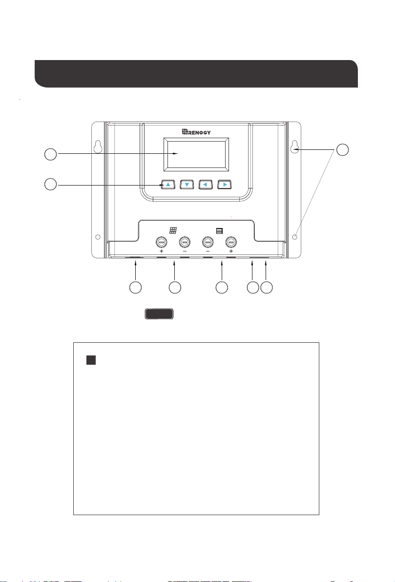
Identification of Parts
3
4 6
5
2
1
7 8
40A MPPT Charge Controller
ROVER ELITE
NOTE
Key Parts
1. LCD Screen
2. Operating Keys
3. Mounting Holes
4. RS485 Communication port
5. PV Terminals
6. Battery Terminals
7. Remote Temperature Sensor Port
8. Battery Voltage Sensor Port
Rover Elite 40A
05
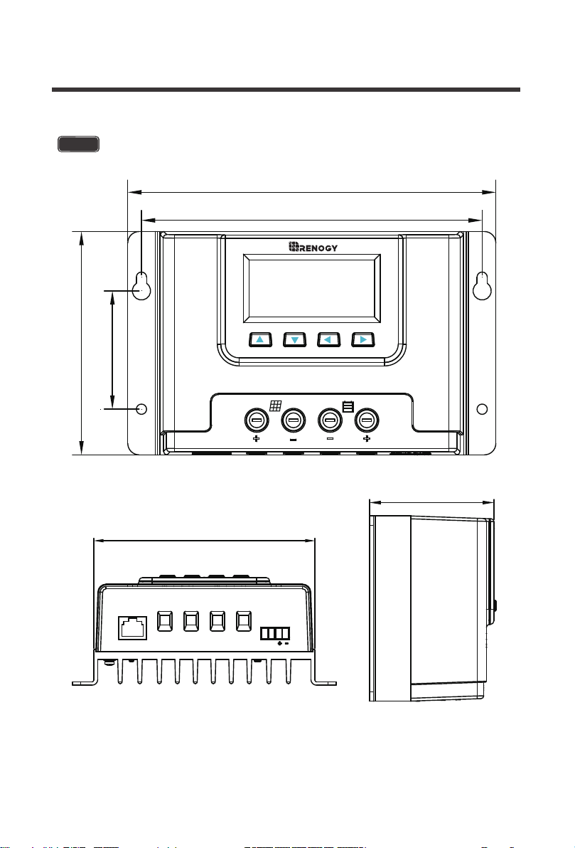
Rover Elite 20
RS485
TEMP BATT
20A MPPT CHARGE CONTROLLER
ROVER ELITE
161.5mm
6.36in
97.9mm
3.85in
51.9mm
2.04in
149.5mm
5.89in
135.5mm
5.33in
65.8mm
2.59in
06
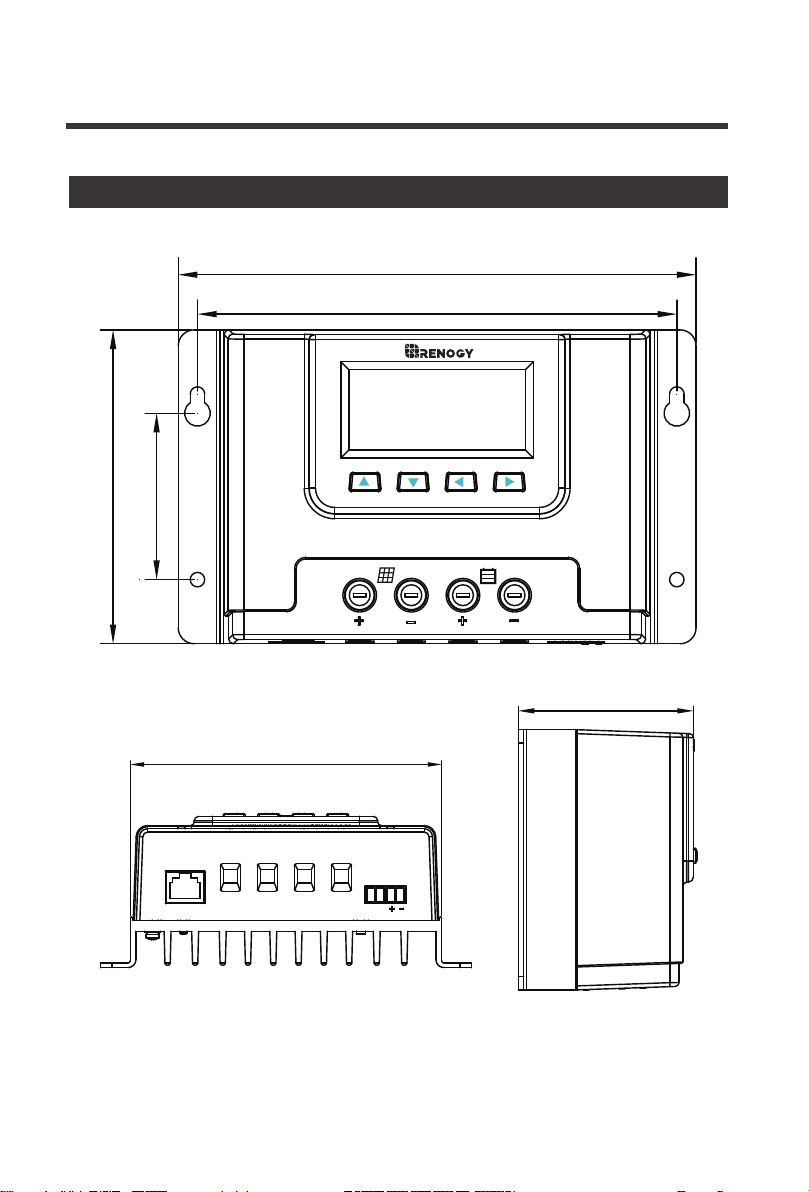
Dimensions
07
Dimensions are in mm [inches]
NOTE
Rover Elite 40
RS485
TEMP BATT
40A MPPT CHARGE CONTROLLER
ROVER ELITE
199.5mm
7.85in
129.9mm
5.11in
89.9mm
3.54in
187.5mm
7.38in
173.5mm
6.83in
75.0mm
2.95in
08
NOTE
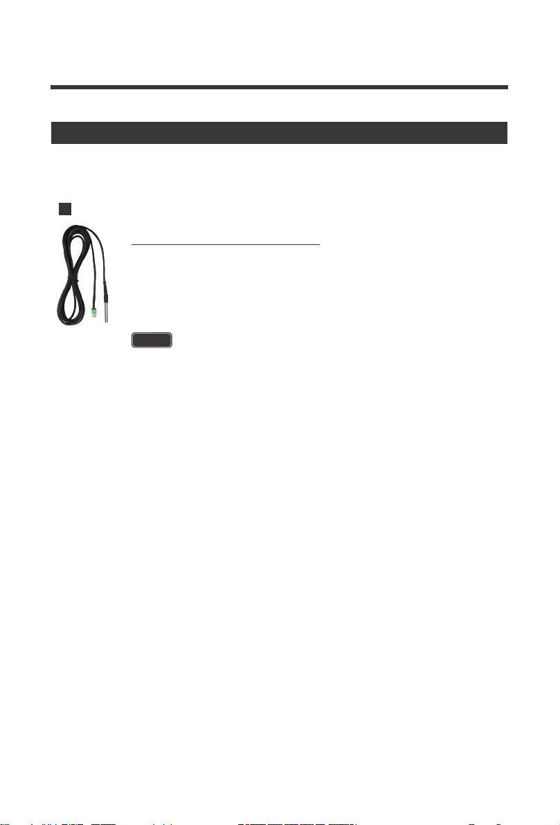
Additional Components
Additional components included in the package:
This sensor measures the temperature at the battery and uses this data for
very accurate temperature compensation. The sensor is supplied with a 9.8ft
cable length that connects to the charge controller. Simply connect the cable
and adhere the sensor on top or the side of the battery to record ambient
temperature around the battery.
Lithium batteries do not have temperature compensation.
Remote Temperature Sensor:
09
Installation
Connect battery terminal wires to the charge controller FIRST then connect the
solar panel(s) to the charge controller. NEVER connect solar panel to charge
controller before the battery.
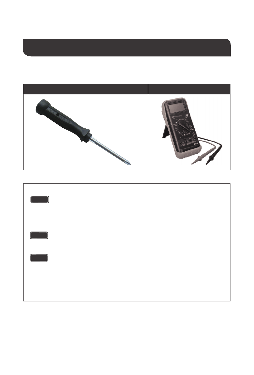
Recommended tools to have before installation:
Screwdriver
Do not over tighten the screw terminals. This could potentially break
the piece that holds the wire to the charge controller.
Refer to the technical specifications for max wire sizes on the control-
ler and for the maximum amperage going through wires.
You are now ready to begin connecting your battery to your charge
controller.
Multi-Meter
CAUTION
CAUTION
WARNING
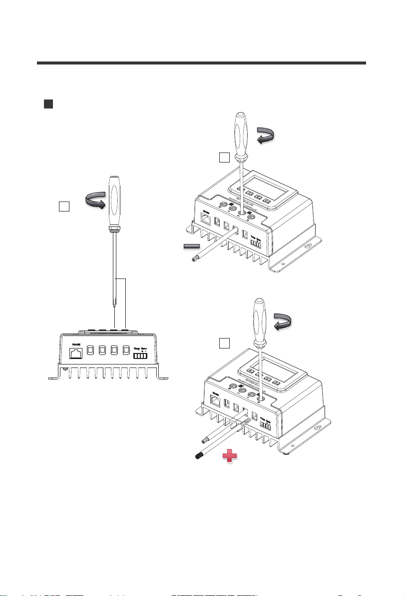
Battery
1
2
3
10
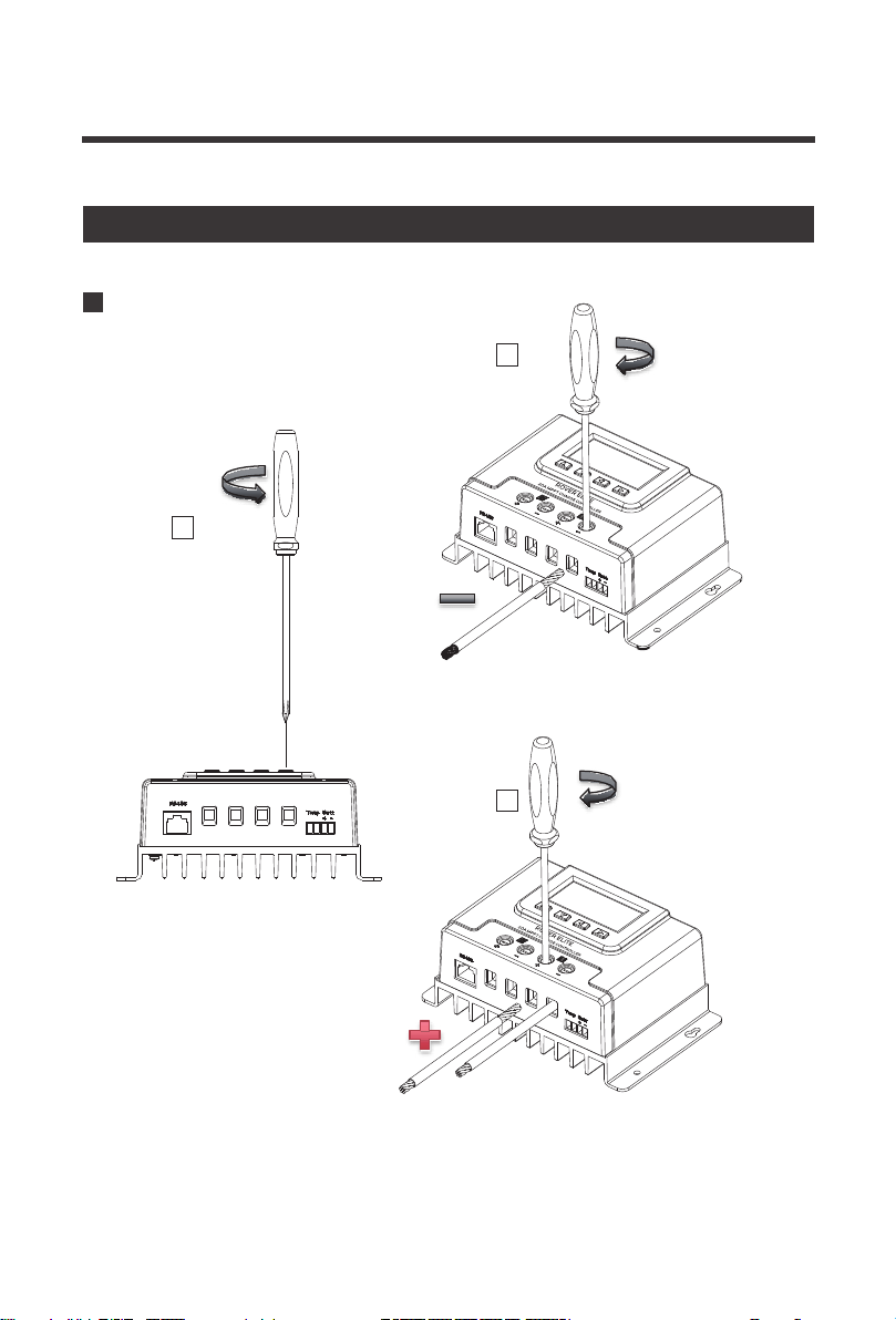
Connect the Charge Controller
Rover Elite 20A
counterclockwise
clockwise
clockwise
1
2
3
11
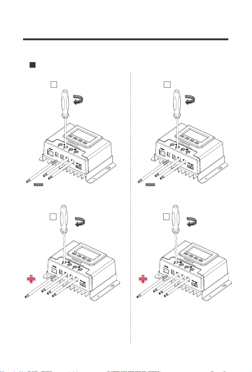
Battery
Rover Elite 40A
counterclockwise
clockwise
clockwise
1
2
Solar Panels
1
2
12
Rover Elite 20A Rover Elite 40A
clockwise clockwise
clockwise clockwise
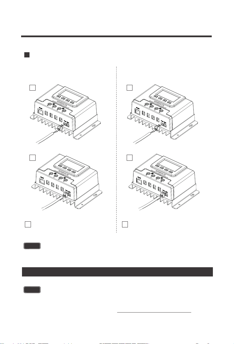
13
Temperature Sensor
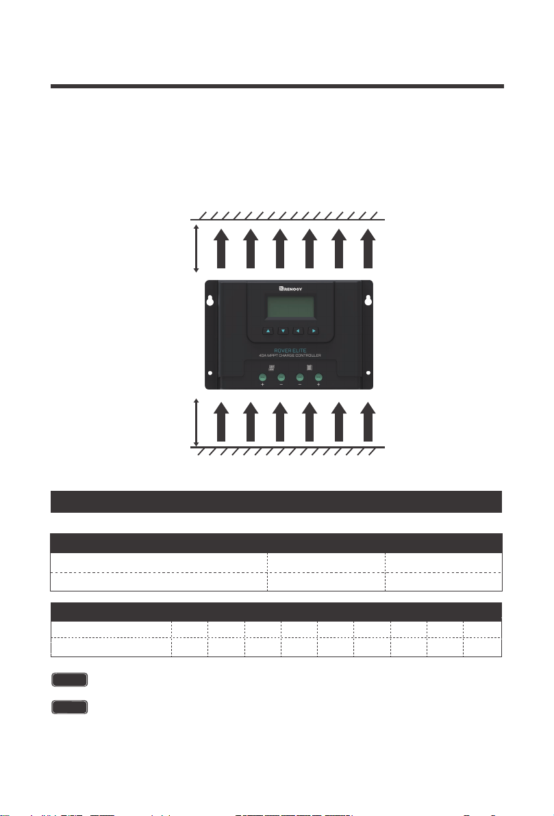
Never install the controller in a sealed enclosure with flooded batteries. Gas can
accumulate and there is a risk of explosion.
1. Choose Mounting Location—place the controller on a vertical surface protected from
direct sunlight, high temperatures, and water. Make sure there is good ventilation.
NOTE
WARNING
1
3
Place the sensor close to the battery
Do NOT place the Temperature Sensor lug inside the battery cell.
2
1
3
Place the sensor close to the battery
2
Mount the Charge Controller
Rover Elite 40ARover Elite 20A
14
2. Check for Clearance—verify that there is sufficient room to run wires, as well as clearance
above and below the controller for ventilation. The clearance should be at least 6 inches (150mm).
3. Mark Holes
4. Drill Holes
5. Secure the charge controller.
6 inches
warm air
(150mm)
cool air
6 inches
(150mm)
Distance Wiring
Cable Total Length One-Way Distance
Cable Size (AWG)
< 10ft
14-12AWG
10ft-20ft
12-10AWG
The solar controller should be installed as near the battery as possible to avoid
efficiency loss.
NOTE
When the connections are completed correctly, the solar controller will turn on and
begin working automatically.
NOTE
AWG 16 14 12 10 8 6 4 2 0
Max. Current
55A30A20A15A10A
75A
95A
130A 170A
NEC Maximum Current for different Copper Wire Sizes
Cable Sizing
15
Operation
Rover Elite is very simple to use. Simply connect the batteries, and the controller will
automatically determine the battery voltage. The controller comes equipped with an LCD
screen and 4 buttons to maneuver though the menus.
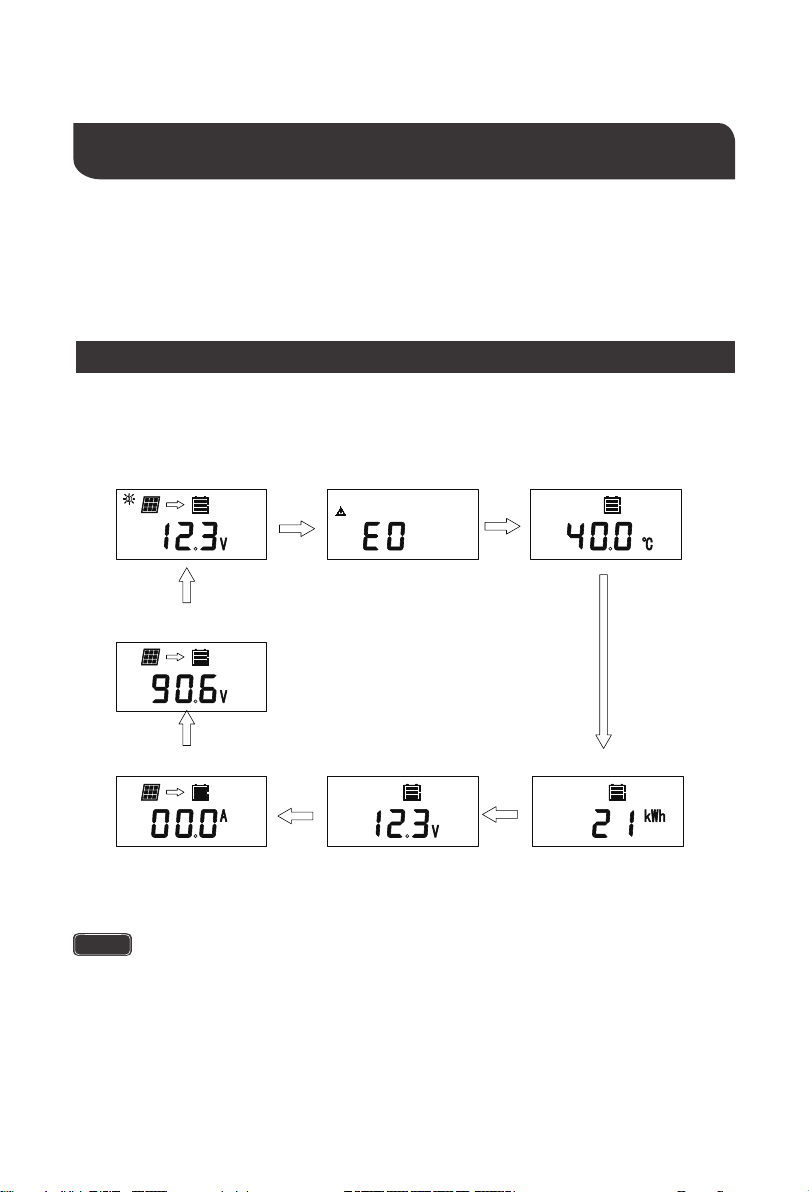
The Error Code will not display unless there is an error. The menu will normal-
ly go from ambient temperature back to the main screen
Main Display
NOTE
Main Screen
Error Code
User Interface
BATT
12V
BATT
Charging Current
12V
Accumulated AH
12V
Ambient Temperature
12V
Solar Panel Voltage
PV
12V
MPPT
Battery Voltage
12V
BATT
16
Cycles backwards through the menu
Return to previous page
in Parameter Setting Mode
Hold to Enter Parameter Setting Mode
Hold to Save Parameter Mode
Cycles forward through the menu
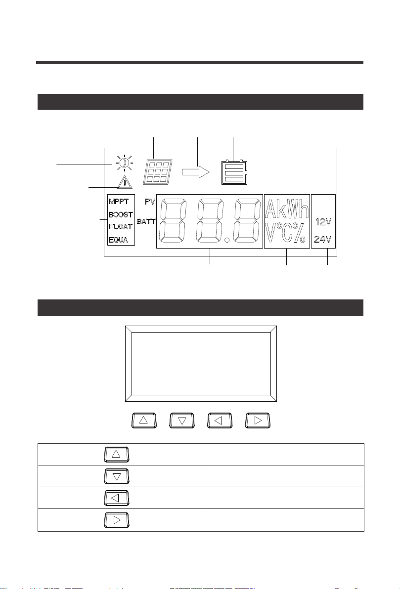
Daytime/Nighttime
mode
solar panel
charging battery
abnormality
charging stage
parameter value unit system voltage
LCD Indicators
change the parameters
17
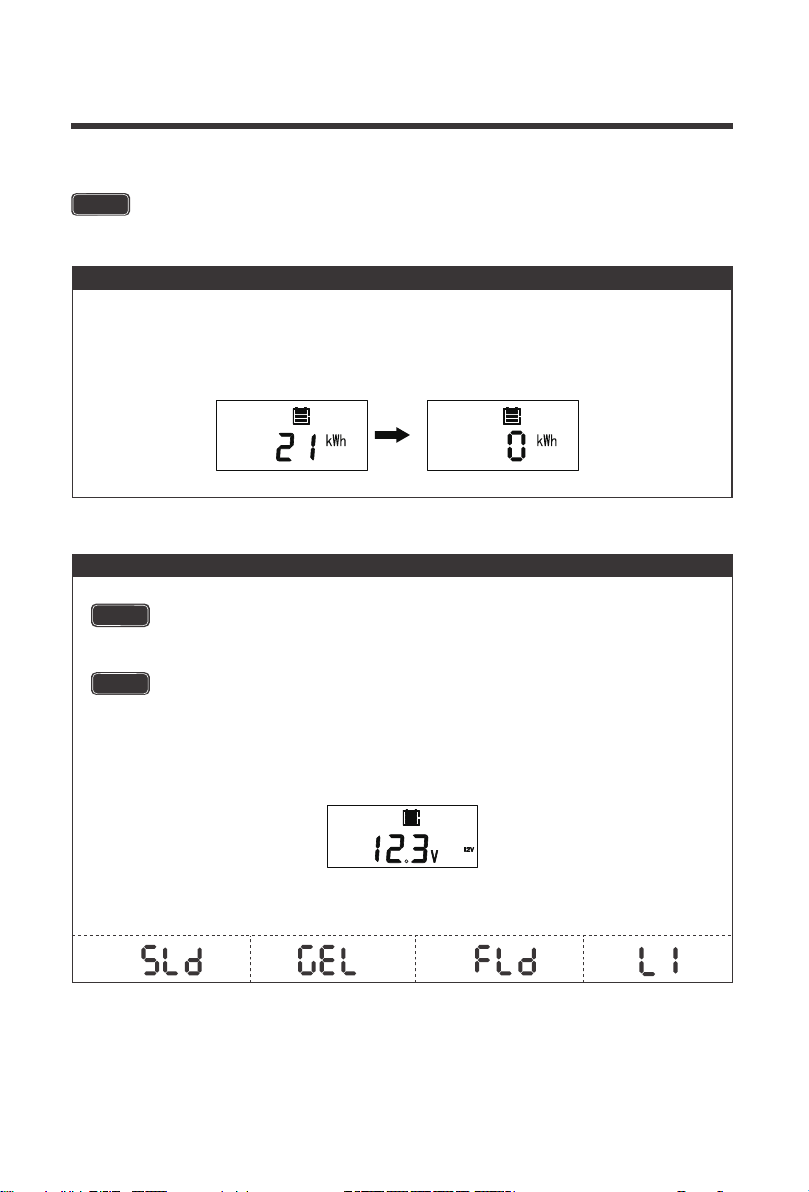
NOTE
1. Clear overall power generation to 0 KWh
2. Selecting Battery Type
Press the UP / DOWN ARROW to the appropriate interface in order to change
the specific parameter.
NOTE
Incorrect battery type setting may damage your battery. Please check your
battery manufacturer’s specifications to when selecting battery type.
If selecting Lithium and wanting to set Battery Voltage or Charge Parameters,
go to “3. Select lithium Battery Voltage and Charge Voltage,” later in this table.
The user can switch to the KWh screen by pressing the up/down button. In order to reset
the current power value to 0 KWh, the user needs to long press the right arrow for three
seconds, and then short press the "Up" arrow to clear the value when the power value
flashes.
In the screen showing the battery voltage, hold down RIGHT ARROW for approximately
3-5 seconds before the screen flashes the current battery type.
Once flashing, use the UP or DOWN ARROW to select the proper battery type and then
hold down RIGHT ARROW again to lock in the selected battery type.
WARNING
SLD is referring to AGM battery
12V12V
18
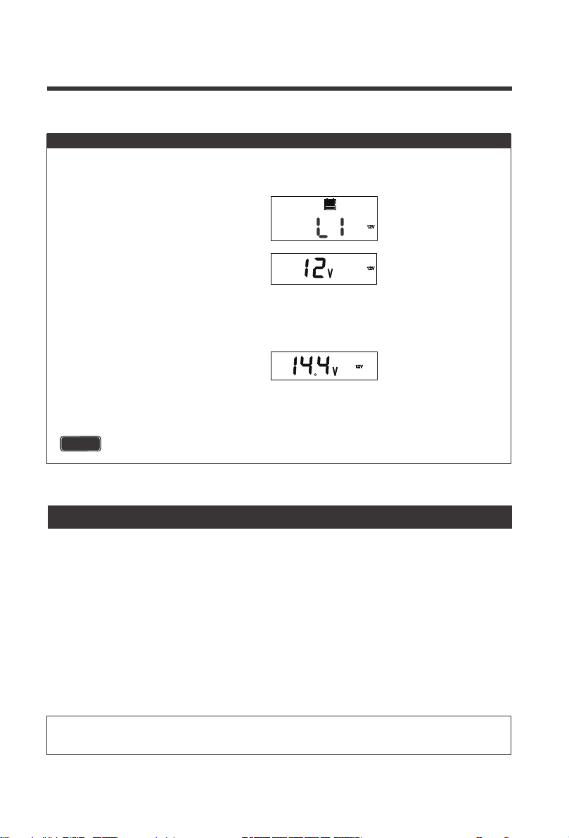
NOTE
If you want 12V LI charging, then select the RIGHT ARROW again to move to LI Boost
Charging Voltage. If you want a 24V LI charging, then you select UP or DOWN ARROW
to move from 12V to 24V LI Charging. Once you confirm your LI Charging (12V or 24V)
press RIGHT ARROW to move to LI Boost Charging Voltage.
Press UP or DOWN ARROW to change the Boost Voltage. The default setting is 14.4V
and the user can set it in the range 12.0~16.0V, in .2 increments. Once done, hold RIGHT
ARROW to confirm the selection.
Once LI is flashing, select RIGHT
ARROW again and a 12V will flash
In the screen showing the battery voltage, hold down RIGHT ARROW for approximately
3-5 seconds before the screen flashes the current battery type. Once flashing, use the
UP or DOWN ARROW to highlight LI
3. Select Lithium Battery Voltage and Charge Voltage
CHG
The above settings are ONLY available for LI setting
MPPT Technology
Therefore, assuming 100% efficiency:
Power In = Power Out
Volts In * Amps In = Volts out * Amps out
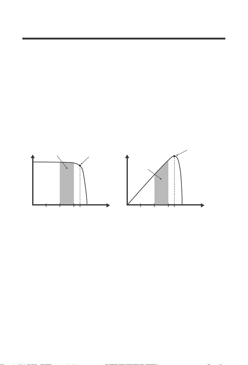
The MPPT Charge Controller utilizes Maximum Power Point Tracking technology to extract
maximum power from the solar module(s). The tracking algorithm is fully automatic and
does not require user adjustment. MPPT technology will track the array’smaximum power
point voltage (Vmp) as it varies with weather conditions, ensuring that the maximum power is
harvested from the array
throughout the course of the day.
In many cases, the MPPT charge controller will “boost” up the current in the solar system. The
current does not come out of thin air. Instead, the power generated in the solar panels is the
same power that is transmitted into the battery bank. Power is the product of Voltage (V) x
Amperage (A).
Current Boost
19
Although MPPT controllers are not 100% efficient, they are very close at about 92-95% efficient.
Therefore, when the user has a solar system whose Vmp is greater than the battery bank
voltage, then that potential difference is proportional to the current boost. The voltage generated
at the solar module needs to be stepped down to a rate that could charge the battery in a stable
fashion by which the amperage is boosted accordingly to the drop. It is entirely possible to have
a solar module generate 8 amps going into the charge controller and likewise have the charge
controller send 10 amps to the battery bank. This is the essence of the MPPT charge controllers
and their advantage over traditional charge controllers. In traditional charge controllers, that
stepped down voltage amount is wasted because the controller algorithm can only dissipate it
as heat. The following demonstrates a graphical point regarding the output of MPPT technology.
The Rover Elite MPPT charge controller has a 4-stage battery charging algorithm for a rapid,
efficient, and safe battery charging. They include: Bulk Charge, Boost Charge, Float Charge,
and Equalization.
Four Charging Stages
Temperature is a huge enemy of solar modules. As the environmental temperature
increases, the operating voltage (Vmp
) is reduced and limits the power generation of the solar
module. Despite the effectiveness of MPPT technology, the charging algorithm will
possibly
not have much to work with and therefore there is an inevitable decrease in
performance.
In this scenario, it would be preferred to have modules with higher nominal
voltage, so that
despite the drop in performance of the panel, the battery is still receiving
a current boost
because of the proportional drop in module voltage.
Limiting Effectiveness
Maximum
Power Point
Traditional
Controller
Operating
Range
Maximum
Power Point
Current vs. Voltage (12V System) Output Power(12V System)
Typical Battery
Voltage Range
CURRENT
VOLTAGE
10 15 17
CURRENT
VOLTAGE
10 15 17
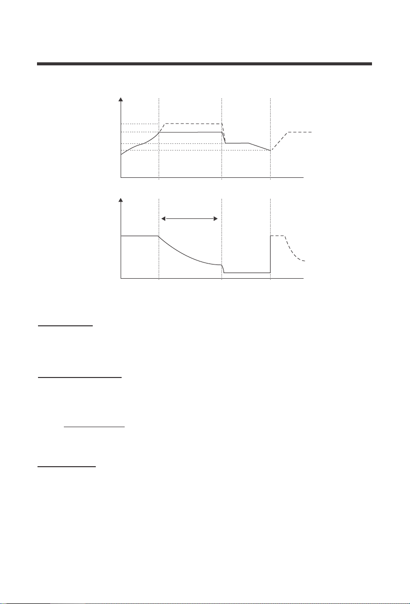
Bulk Charge: This algorithm is used for day to day charging. It uses 100% of available solar
power to recharge the battery and is equivalent to constant current. In this stage the battery
voltage has not yet reached constant voltage (Equalize or Boost), the controller operates in
constant current mode, delivering its maximum current to the batteries (MPPT Charging) .
Float Charge: After the constant voltage stage, the controller will reduce the battery voltage
to a float voltage set point. Once the battery is fully charged, there will be no more chemical
reactions and all the charge current would turn into heat or gas. Because of this, The charge
controller will reduce the voltage charge to smaller quantity, while lightly charging the battery.
The purpose for this is to offset the power consumption while maintaining a full battery storage
capacity. In the event that a load drawn from the battery exceeds the charge current, the control-
ler will no longer be able to maintain the battery to a Float set point and the controller will end the
float charge stage and refer back to bulk charging.
Constant Charging: When the battery reaches the constant voltage set point, the controller
will start to operate in constant charging mode, where it is no longer MPPT charging. The current
will drop gradually. This has two stages, equalize and boost and they are not carried out constantly
in a full charge process to avoid too much gas precipitation or overheating of the battery.
Boost Charge:
Boost stage maintains a charge for 2 hours by default. The user
can adjust the constant time and preset value of boost per their demand.
20
Battery
Voltage
Equalize
Boost
Float
Recharge
Bulk Charge
A B C
Constant charging
Cumulative Time:3h
Float Charge
Boost
Time
Battery
Current
Time
Bulk
Max Current
Duration Time:2h
(Range:10-180min)
21
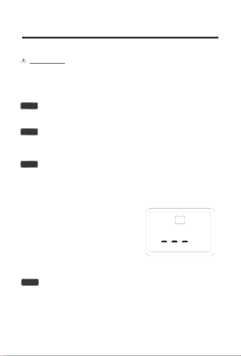
The Rover Elite MPPT charge controller has a reactivation feature
to awaken a sleeping lithium battery. The protection circuit of
lithium battery will typically turn the battery off and make it
unusable if over-discharged. This can happen when storing a
lithium battery pack in a discharged state for any length of time as
self-discharge would gradually deplete the remaining charge.
Without the wake-up feature to reactivate and recharge batteries,
these batteries would become unserviceable and the packs would
be discarded. The Rover Elite will apply a small charge current to
activate the protection circuit and if a correct cell voltage can be
reached, it starts a normal charge.
The image on the right shows the activation interface of lithium
battery.
Lithium Battery Activation
Equalization: Is carried out every 28 days of the month. It is intentional overcharging of
the battery for a controlled period of time. Certain types of batteries benefit from periodic
equalizing charge, which can stir the electrolyte, balance battery voltage and complete
chemical reaction. Equalizing charge increases the battery voltage, higher than the standard
complement voltage, which gasifies the battery electrolyte.
When using the Rover Elite to charge a 24V lithium battery bank, set the
system voltage to 24V instead of auto recognition. To change the system
voltage, press the Up or Down buttons then long press Right Arrow to save the
selected system voltage.
CAUTION
Equalization may increase battery voltage to a level damaging to sensitive DC loads.
Ensure that all load allowable input voltages are greater than the equalizing charging
set point voltage.
Once equalization is active in the battery charging, it will not exit this stage unless
there is adequate charging current from the solar panel. There should be NO load on
the batteries when in equalization charging stage.
WARNING
Over-charging and excessive gas precipitation may damage the battery plates and
activate material shedding on them. Too high of equalizing charge or for too long
may cause damage. Please carefully review the specific requirements of the battery
used in the system.
WARNING
WARNING

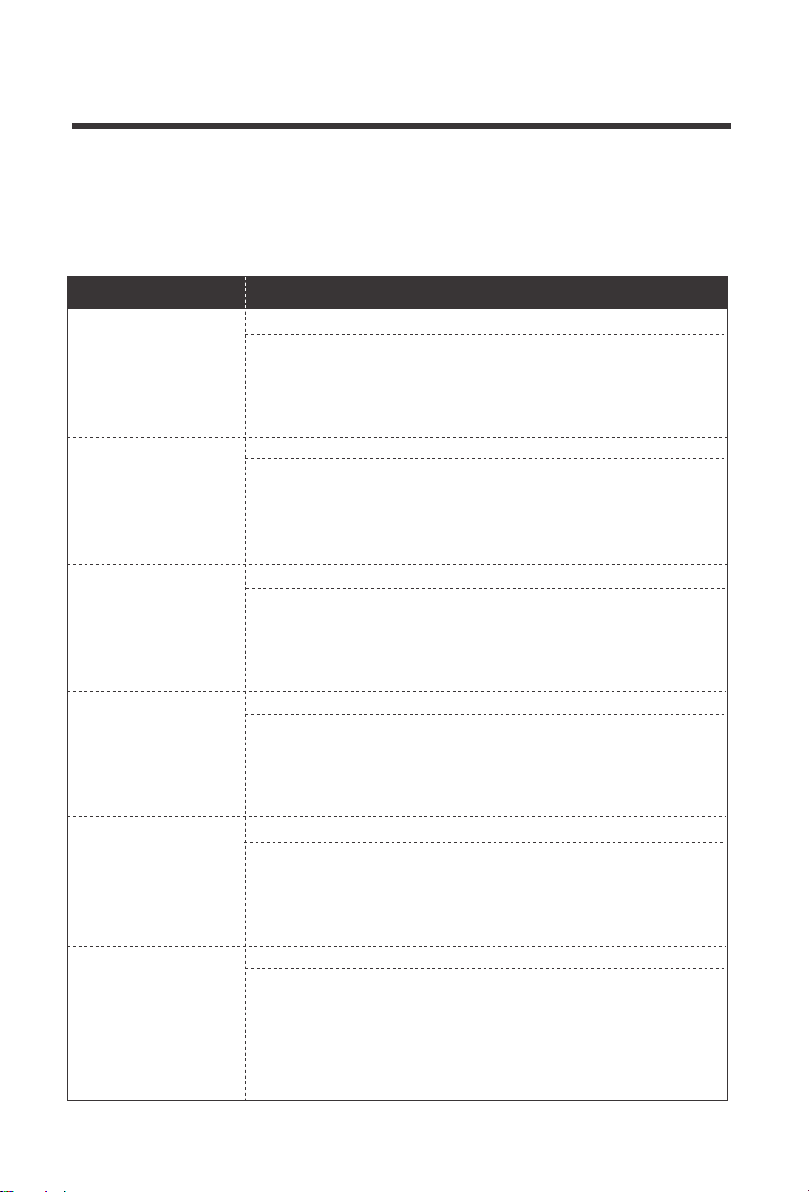
If the Rover Elite is not functioning properly, it will display an error code not normally seen in the
interface display. Depending on the code, you may attempt to troubleshoot the error to
commence normal system operation.
System behaving normally, no action needed. You will not
see this error code.
Use a multi-meter to get a reading of the battery voltage in
volts DC to validate error code. Battery is very low. Disconnect
any loads to the battery and let the solar system charge the
battery backup. If the battery voltage is low it may be in open
battery protection mode, which is a Rover Elite Protection.
Make sure controller is in ventilated area and that the appro-
priate wire sizes are used to connect to and from the control-
ler. This may be creating heating issues inside the controller.
The controller will resume normal operation upon cooling
down.
Use a multi-meter to get a reading of the battery voltage in volts DC
to validate error code. Battery is charging very high and approached
16VDC. Disconnect any external chargers and isolate which
charger is overcharging battery. Eliminate from system.
Record the ambient temperature found in the controller
screen. Make sure the controller is not placed in direct line of
heating sources or that it is over-heating due to over-sun
exposure. The controller will resume normal operation upon
cooling down.
The controller has a maximum dc voltage input of 100DC. If
connecting your panels in series, make sure the reading does
not go over this limit. Check with a multi-meter before
connecting to the controller to ensure you’re within this
specification. This might require using less panels.
The battery cables are reversed. Use a multi-meter to make sure
your voltage reading has the correct polarity (Red to positive and
Black to negative) with a positive number in volts DC. If the
number is negative, switch the positive and negative battery
cables in the battery terminal of the Rover Elite.
The solar panel wires are connected in reverse polarity. Verify
using a multi-meter to make sure your voltage reading has the
correct polarity with a positive number in volts DC.
Troubleshooting
Error Codes / Troubleshooting
E0
E01
E02
E06
E10
E13
Error Code Meaning Troubleshoot
E07
E14
No Error
Over-
discharged
battery
Battery
Over-
charging
Controller
internals
over
temperature
PV Over-
voltage
PV reverse-
polarity
Controller is
over-
temperature
Battery
reverse
polarity
22
Protection Behaviors / Fixes
Behavior Protective Function / Fixes
Reverse Battery Polarity Protection
The Rover Elite needs a correct battery connection to startup. This
might mean that the battery cables are reversed. Use a multi-meter
to make sure your voltage reading has the correct polarity (Red to
positive and Black to negative) with a positive number in volts DC.
If the number is negative, switch the positive and negative battery
cables in the battery terminal of the Rover Elite.
Solar Panels Reverse Polarity Protection
The solar panel wires are connected in reverse polarity. Verify
using a multi-meter to make sure your voltage reading has the
correct polarity with a positive number in volts DC. In some cases,
with the battery and solar panels both connected in reverse polarity,
the controller will not turn on, but the controller is not damaged.
Simply correct the reverse polarity to continue normal operation.
Solar Panels Over voltage
The controller has a maximum dc voltage input of 100DC. If connecting
your panels in series, make sure the reading does not go over this limit.
Check with a multi-meter before connecting to the controller to ensure
you’re within this specification. This might require using less panels to
make sure you are within the Rover Elite specified input.
E02 Battery Overcharging
If the battery was charging fine and stopped, it could be because it
was being overcharged by the solar source if not an external
source. You might see an E02 display or perhaps an empty
screen. Make sure your charging sources are not charging at
16VDC or check to see if your batteries are being equalized, an
intentional over-charging, that might be triggering this error.
Current Limiting / E06 / E07
The max amp charging from the Rover Elite will be the respective
amp rating. The Rover Elite will current limit any excess amperage
than the rating of the controller, however, be cautious as this might
create excess heat and put the controller in an internal/external
temperature protection mode which will halt the controller perfor-
mance until it can cool down and function normally again.
Open Battery Protection Mode
Whether connecting the system for the first time or operating it for
a while, you may experience an E01 error if the controller does not
actually detect a battery and assumes it to be under-discharged.
This can happen in an accidental line break or failure to connect it
correctly the first time. This will not damage the controller, but you
will need to make sure the battery voltage is the same as the
battery terminal voltage or check for continuity. Once fixed, normal
operation should continue.
The charge
controller believes
the battery is
over-discharged,
but it is not
Current Limiting /
Temperature
Protection
My system
stopped charging
When connecting
solar panels to the
controller it sounds
an alarm
The battery and solar
panels are connected
to the controller, but
the controller shows
nighttime.
The battery is
connected to the
controller, but the
controller is not
turning on
If the Rover Elite is not functioning properly and is not displaying an error code, it may be under-
going an automatic protection function. This does not mean your Rover Elite is defective, but it
requires some troubleshooting to commence normal system operation.
23
24
Maintenance
For best controller performance, it is recommended that these tasks be performed from time to time.
1.Check wiring going into the charge controller and make sure there is no wire damage or wear.
3.Occasionally clean the case using a damp cloth
2.Tighten all terminals and inspect any loose, broken, or burnt up connections
Technical Specifications
Model
Nominal system voltage
Max. Battery Voltage
Max Solar Input Voltage
Temp. Compensation
RCC20RVRE-G1 RCC40RVRE-G1
Max. Solar Input Power
Rated Battery Current
Self-Consumption
20A
32V
100
VDC
12V/24V Auto Recognition
12V @ 260W 24V @ 520W
≤1.5W
-3mV/℃/2V, excludes LI
40A
12V @ 520W 24V @ 1040W
Model
Battery Types
20-6 AWG
-20℃ ~ 45℃ / -4°F ~ 113°F
Dimensions
Weight
RCC20RVRE-G1 RCC40RVRE-G1
Humidity Range
Enclosure
Communication
161.5 * 97.9 * 66.5 mm
6.36 * 3.85 * 2.62 in
199.5*130*76.7 mm
7.85*5.12*3.02 in
0.75 kg 1.65 lbs 1.364 kg 3.01 lbs
≤95% (NC)
SLD/AGM, GEL, FLD, LI
Common NegativeGrounding Type
Terminal Size
Operating Temperature
Storage Temperature
-40℃ ~ 80℃ / -40°F ~ 176°F
IP32
RS485
Certification FCC Part 15 Class B; CE; RoHS; RCM
Electrical Parameters
General

25
Battery Charging Parameters
Battery FLOODED LI(LFP)
High Voltage
Over Voltage Reconnect
Disconnect
16 V 16 V
15 V 15 V
Equalization Voltage -----
Boost Charge Voltage
Float Charge Voltage 13.8 V
-----
Boost Return Voltage
13.2 V 13.2 V
Over-discharge Recover
12.6 V 12.6 V
Over-discharge Warning
11.1 V 11.1 V
Equalization Interva
30 Days
Equalization Duration
Boost Duration
2 hours
2 hours
-----
-----
-----
14.8V
14.6 V
SLD/AGM
16 V
15 V
-----
-----
-----
13.8 V
13.2 V
12.6 V
11.1 V
14.6 V
GEL
16 V
15 V
-----
-----
-----
13.8 V
13.2 V
12.6 V
11.1 V
2 hours2 hours
14.2 V
This equipment has been tested and found to comply with the limits for a class B digital
device, pursuant to part 15 of the FCC Rules. These limits are designed to provide reasonable
protection against harmful interference in a residential installation. This equipment generates,
uses and can radiate radio frequency energy and if not installed and used in accordance with
the instructions, may cause harmful interference to radio communications. However, there is
no guarantee that interference will not occur in a particular installation. If this equipment does
cause harmful interference to radio or television reception, which can be determined by
turning the equipment off and on, the user is encouraged to try to correct the interference by
one or more of the following measures:
• Reorient or relocate the receiving antenna.
• Increase the separation between the equipment and receiver.
• Connect the equipment into an outlet on a circuit different from that to which the receiver is connected.
• Consult the dealer or an experienced radio/TV technician for help.
This device complies with Part 15 of the FCC Rules.
Operation is subject to the following two conditions:
(1) this device may not cause harmful interference, and
(2) this device must accept any interference received, including interference that may cause
undesired operation.
14.4V
User:12.0V-16V
Temp 25℃
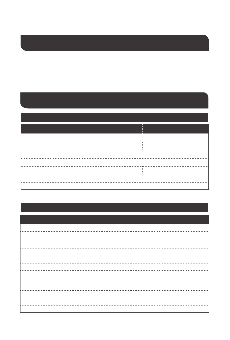
MPPT 12V conversion efficiency (12V battery)
1.12 Volt System Conversion Efficiency
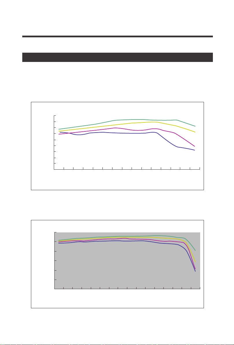
2. 24 Volt System Conversion Efficiency
Illumination Intensity: 1000W/ m
2
Conversion efficiency Conversion efficiency
Output power(W)
MPPT 24V conversion efficiency (24V battery)
Output power(W)
26
Rover Elite– Conversion Efficiency Curves
96%
95%
94%
93%
92%
91%
90%
89%
88%
96%
98%
94%
92%
90%
88%
86%
87%
550
1100 1000 900 800 600 500 300 100
500 475 450 425 400 375 350 300 250 200 150 50100525
20 Vmp
40 Vmp
60 Vmp
75 Vmp
20 Vmp
40 Vmp
60 Vmp
75 Vmp

RENOGY.COM
US
2775 E Philadelphia St, Ontario, CA 91761, USA
909-287-7111
www.renogy.com
support@renogy.com
https://www.renogy.cn
support@renogy.cn
CN
400-6636-695
苏州高新区科技城培源路1号5号楼-4
CA
https://ca.renogy.com
supportca@renogy.com
https://au.renogy.com
supportau@renogy.com
AU
JP
https://www.renogy.jp
supportjp@renogy.com
https://uk.renogy.com
supportuk@renogy.com
UK
https://de.renogy.com
supportde@renogy.com
DE
Renogy reserves the right to change
the contents of this manual without notice.