Loading ...
Loading ...
Loading ...
25
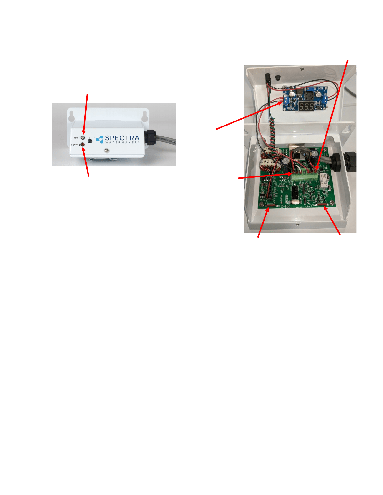
Switch 1
There are 7 pins on the phoenix connector from le to right:
Pin 1 Supply Voltage-Baery ( + )
Pin 2 Ground
Pin 3 Trigger
Pin 4 Auxiliary Output 1
Pin 5 Auxiliary Output 2
Pin 6 To ion generator (bowl). No polarity.
Pin 7 To ion generator (bowl). No polarity.
Auxiliary Outputs 1 and 2 are switched to the supply voltage when turned on. These outputs are protected by 100mA
self reseng fuses.
Output 1 – ON during generang cycle – intended to drive a pump relay on some systems
Output 2 – ON when cycle counter reaches pre-programmed number (usually 720), when generator element may
need replacement and should be tested and/or inspected.
Operaon – LEDS
Power-up indicaon – fast red/green ash for a few seconds
Ready, Idle – solid green
Generang – the LED will quickly ash at a programmed interval (factory set to 17 seconds between ashes.)
The ash color with alternate between green and amber and will be o in between voltage spikes. The
color change symbolizes the polarity alternang from posive to negave.
Bad power – fast red ash followed by shut down
High temperature – fast red ash
Cycle counter reached limit—slow red ash
Switch 2
Pin 1
Pin 7
Run Light
Will be green when while Z-Ion is
powered and ready
Service Light
Figure 1
Voltage
Spike Counter
Z-Ion Layout and Specs.
Loading ...
Loading ...
Loading ...