For more information, visit online at
www.brutepower.com
Brute is a registered trademark of
Briggs & Stratton Corporation and is
used under license to Ardisam, Inc.
P/N: 23148
ECN: 10990
REV2: 10/20/2015
© 2015 Ardisam, Inc.
All Rights Reserved.
Operator’s Manual
Front Tine Tiller
PRODUCT NUMBER:
22419
SN
Not for Reproduction
For additional information visit online at www.brutepower.com or call 800-743-4115 M-F 8-5 CST
Operator’s Manual
Front Tine Tiller
2
INTRODUCTION
Thank you for purchasing the Front Tine Tiller from Brute® We have worked to ensure that this tiller meets the highest standards
for usability and durability. With proper care, your tiller will provide many years of service.
Please read this entire manual before installation and use. Brute® reserves the right to change, alter or improve the prod-
uct and this document at any time without prior notice.
CONTENTS
Introduction/Contents/Registration and Service ............................................................................................................................................................. 2
Warnings and Safety Precautions ....................................................................................................................................................................................... 3-6
Safety Decals .................................................................................................................................................................................................................................. 7
Hazard Symbols and Meanings ...............................................................................................................................................................................................8
Features ...........................................................................................................................................................................................................................................9
Unpacking and Assembly ................................................................................................................................................................................................ 10-12
Controls and Operating Symbols/Controls ................................................................................................................................................................ 12-13
Operation ......................................................................................................................................................................................................................................14
Maintenance ......................................................................................................................................................................................................................... 15-17
Storage ...........................................................................................................................................................................................................................................17
Troubleshooting and Repair ...................................................................................................................................................................................................18
Warranty Terms and Conditions ............................................................................................................................................................................................19
Illustrated Parts Breakdown............................................................................................................................................................................................. 20-25
OWNERSHIP RECORDS
Owner’s Name:
Owner’s Address:
City: State/Province: Zip Code/Postal Code:
Model Number: Serial Number:
Date of Purchase:
Notes:
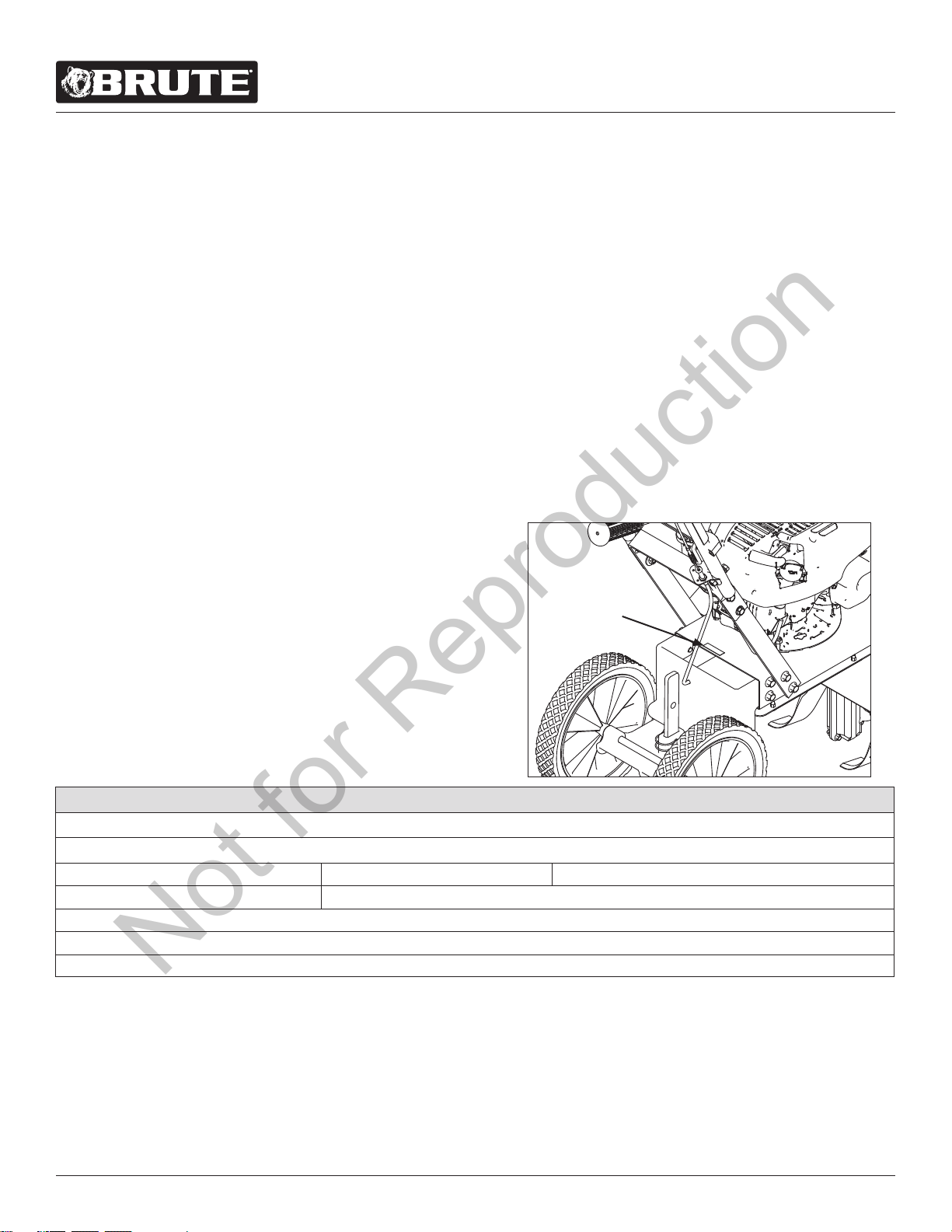
Record the product model number and serial number in the space
provided for easy reference when ordering parts or requesting tech-
nical support. Excluding emissions-related warranty items, the war-
ranty is valid only if the completed registration is received by Brute®
within 30 days of purchase. (SEE WARRANTY SECTION FOR MORE
INFORMATION) You can register your warranty by mailing it to:
Brute, PO Box 702, Milwaukee, WI 53201-0702. You may also call our
Customer Service department at 800-743-4115 Mondays through
Fridays from 8 a.m. to 5 p.m. CST.
Read and keep this manual for future reference. This manual contains important information on SAFETY, ASSEMBLY, OP-
ERATION, AND MAINTENANCE. The owner must be certain that all the product information is included with the unit. This
information includes the MANUAL, the REPLACEMENT PARTS and the WARRANTIES. This information must be included to
make sure state laws and other laws are followed. All persons to whom rent/loan this unit must have access to and under-
stand this information. This manual should remain with the product even if it is resold.
Registration and Service
Serial Decal
Number
Not for Reproduction
For additional information visit online at www.brutepower.com or call 800-743-4115 M-F 8-5 CST
Operator’s Manual
Front Tine Tiller
3
WARNINGS AND SAFETY PRECAUTIONS
Owner’s Responsibility
Accurate assembly and safe and eective use of the machine is
the owner’s responsibility.
• Read and follow all safety instructions.
• Carefully follow all assembly instructions.
• Maintain the machine according to directions and
schedule included in this Brute® operator’s manual.
• Ensure that anyone who uses the machine is familiar
with all controls and safety precautions.
Special Messages
Your manual contains special messages to bring attention to
potential safety concerns, machine damage as well as helpful
operating and servicing information. Please read all the infor-
mation carefully to avoid injury and machine damage.
NOTE: General information is given throughout the
manual that may help the operator in the
operation or service of the machine.
THIS SYMBOL POINTS OUT IMPORTANT
SAFETY INSTRUCTIONS WHICH IF NOT
FOLLOWED COULD ENDANGER YOUR
PERSONAL SAFETY. READ AND FOLLOW ALL
INSTRUCTIONS IN THIS MANUAL BEFORE
ATTEMPTING TO OPERATE THIS EQUIPMENT.
Before Operating Equipment:
Please read this section carefully. Read entire operating and
maintenance instructions for this product. Failure to follow in-
structions could result in serious injury or death. Operate the
machine according to the safety instructions outlined here and
inserted throughout the text. Anyone who uses this machine
must read the instructions and be familiar with the controls.
Intended Use / Foreseeable Misuse
IMPORTANT: This is a motorized rotary tiller that works the
soil by means of rotating tines. It is pedestrian-controlled, but
not self-propelled, with a gasoline-fueled internal combustion
engine to power the tines. It shall not be used for any other
purpose.
WARNING
WARNING INDICATES A HAZARD WHICH, IF NOT
AVOIDED, COULD RESULT IN DEATH OR SERIOUS
INJURY AND/OR PROPERTY DAMAGE.
CAUTION
CAUTION INDICATES YOUR EQUIPMENT CAN BE
DAMAGED IF THE SAFETY INSTRUCTIONS THAT
FOLLOW THIS SIGNAL WORD ARE NOT OBEYED.
WARNING
CALIFORNIA PROPOSITION 65 WARNING
ENGINE EXHAUST FROM THIS PRODUCT
CONTAINS CHEMICALS KNOWN TO THE STATE OF
CALIFORNIA TO CAUSE CANCER, BIRTH DEFECTS,
OR OTHER REPRODUCTIVE HARM.
IMPORTANT
INDICATES HELPFUL INFORMATION FOR PROPER
ASSEMBLY, OPERATION, OR MAINTENANCE OF
YOUR EQUIPMENT.
WARNING
YOU MUST READ, UNDERSTAND AND
COMPLY WITH ALL SAFETY AND OPERATING
INSTRUCTIONS IN THIS MANUAL BEFORE
ATTEMPTING TO SETUP AND OPERATE YOUR
MACHINE.
FAILURE TO COMPLY WITH ALL SAFETY AND
OPERATING INSTRUCTIONS CAN RESULT IN LOSS
OF MACHINE CONTROL, SERIOUS PERSONAL
INJURY TO YOU AND/OR BYSTANDERS, AND RISK
OF EQUIPMENT AND PROPERTY DAMAGE. THE
TRIANGLE IN THE TEXT SIGNIFIES IMPORTANT
CAUTIONS OR WARNINGS WHICH MUST BE
FOLLOWED.
DANGER
SRT CRT
Not for Reproduction

For additional information visit online at www.brutepower.com or call 800-743-4115 M-F 8-5 CST
Operator’s Manual
Front Tine Tiller
4
GENERAL SAFETY RULES
• Read, understand, and follow all instructions on the
machine and in the manual(s). Be thoroughly familiar
with the controls and the proper use of the machine
before starting.
• Use this equipment for its intended purpose only.
• Familiarize yourself with all of the safety and
operating decals on this equipment and on any of its
attachments or accessories.
• Do not put hands or feet near or under rotating parts.
• Only allow responsible individuals who are familiar
with the instructions to operate the machine. Do
not allow children to operate this machine. Do not
allow adults to operate the machine without proper
instruction.
• Thoroughly inspect the area where the machine
is to be used and remove all foreign objects. Your
equipment can propel small objects at high speed
causing personal injury or property damage. Stay
away from breakable objects, such as house windows,
automobiles, greenhouses, etc.
• Wear appropriate clothing such as a long-sleeved
shirt or jacket. Also wear long trousers or slacks. Do
not wear shorts. Never wear sandals, sneakers or
open shoes, and never operate the machine with bare
feet.
• Do not wear loose clothing or jewelry. They can get
caught in moving parts. Always keep hands, feet, hair
and loose clothing away from any moving parts on
engine and machine.
• Always wear safety goggles or safety glasses with side
shields when operating the machine to protect your
eyes from foreign objects which can be thrown from
the unit. Always wear a protective hearing device.
• Always wear work gloves and sturdy footwear. Wear
footwear that will improve footing on slippery
surfaces. Leather work shoes or short boots work well
for most people. These will protect the operator’s
ankles and shins from small sticks, splinters, and other
debris.
• It is advisable to wear protective headgear to prevent
the possibility of being struck by small ying particles,
or being struck by low hanging branches, twigs,
or other objects which may be unnoticed by the
operator.
• Do not operate the machine without proper guards or
other safety protective devices in place.
• See manufacturer’s instructions for proper operation
and installation of accessories. Only use accessories
approved by the manufacturer.
• Operate only in daylight or good articial light.
• Do not operate product when fatigued or under the
inuence of alcohol, drugs or other medication which
can cause drowsiness or aect your ability to operate
this machine safely.
• Never operate machine in wet grass. Always be sure
of your footing; keep a rm hold on the handle and
walk; never run.
• Watch for trac when operating machine near, or
when crossing roads.
• If the equipment should start to vibrate abnormally,
stop the engine (motor), ip the ON/OFF switch to the
OFF position. Check immediately for cause. Vibration
is generally a warning of trouble. If the noise or
vibrations of the machine increase, stop immediately
and perform an inspection.
• Never leave the machine unattended when the
engine is running. Flip the ON/OFF switch to the OFF
position.
• Regularly inspect the machine. Make sure parts are
not bent, damaged, or loose.
• Temperature of muer and nearby areas may exceed
150° F (65° C). Allow muer and engine areas to cool
before touching. Never pick up or carry the machine
while the engine is running.
• Prolonged exposure to noise and vibration from gasoline
engine-powered equipment should be avoided. Take
intermittent breaks and/or wear ear protection from
engine noise as well as heavy work gloves to reduce
vibration in the hands.
• Keep all screws, nuts, and bolts tight.
• Do not transport the machine from one place to
another with the engine running.
• When moving the packaged machine, always do so
with a partner.
• Check local regulations for age restrictions on use of
this machine.
Product-Specic Safety Rules
• Do not till above underground utilities, including
water lines, gas lines, electric cables, or pipes. Do
not operate the machine on terrain/soil with large
rocks and foreign objects which can damage the
equipment.
• After striking a foreign object, stop the engine. Flip
the ON/OFF switch to the OFF position. Inspect
the machine for damage. If damaged, repair before
starting and operating the machine.
• The tines of the tiller should not rotate when the drive
control lever is released into the neutral position. If it
does rotate when in neutral, contact Brute® Customer
Service for instruction.
• If an object becomes lodged in the tines, ip the ON/
OFF switch to the OFF position, allow to cool before
attempting to remove the foreign object.
• Pulleys and belts should be kept free of oil or other
moisture for ecient operation.
• Disengage all clutches and leave control lever in the
neutral position before starting the engine.
Not for Reproduction

For additional information visit online at www.brutepower.com or call 800-743-4115 M-F 8-5 CST
Operator’s Manual
Front Tine Tiller
5
ENGINE SAFETY PRECAUTIONS
If your product comes with a separate engine
manual, be sure to read and follow all safety and
warning precautions outlined there, in addition
to any in this manual.
Preventing Carbon Monoxide Poisoning
• Always start and run engine outdoors. Do not start
or run engine in an enclosed area, even if doors or
windows are open.
• Never try to ventilate engine exhaust indoors. Carbon
monoxide can reach dangerous levels very quickly.
• Never run engine outdoors where exhaust fumes may
be pulled into a building.
• Never run engine outdoors in a poorly ventilated area
where the exhaust fumes may be trapped and not
easily taken away. (Examples include: in a large hole
or areas where hills surround your working area.)
• Never run engine in an enclosed or partially enclosed
area. (Examples include: buildings that are enclosed
on one or more sides, under tents, car ports or
basements.)
• Always run the engine with the exhaust and muer
pointed in the direction away from the operator.
• Never point the exhaust muer towards anyone.
People should always be many feet away from the
operation of the engine and its attachments.
• Do not change the engine governor settings or over-
speed the engine.
Gasoline Fires and Handling Fuel Safely
Use extra care in handling gasoline and other fuels. They are
ammable and vapors are explosive.
• When storing extra fuel be sure that it is in an
appropriate container and away from any re hazards.
• Prevent re and explosion caused by static electric
discharge. Use only nonmetal, portable fuel
containers approved by the Underwriter’s Laboratory
(U.L.) or the American Society for Testing & Materials
(ASTM).
• Never remove the fuel cap or add fuel with the engine
WARNING
ENGINES GIVE OFF CARBON MONOXIDE, AN
ODORLESS, COLORLESS, POISONOUS GAS.
CARBON MONOXIDE MAY BE PRESENT EVEN IF
YOU DO NOT SMELL OR SEE ANY ENGINE EXHAUST.
BREATHING CARBON MONOXIDE CAN CAUSE
NAUSEA, FAINTING OR DEATH, IN ADDITION TO
DROWSINESS, DIZZINESS AND CONFUSION.
IF YOU EXPERIENCE ANY OF THESE SYMPTOMS,
SEEK FRESH AIR AND MEDICAL ATTENTION
IMMEDIATELY.
running. Stop engine and allow to cool before lling.
• Do not smoke while using engine or product.
• Never drain fuel from engine in an enclosed area.
• Always ll fuel tank outside in a well ventilated area.
Never ll your fuel tank with fuel indoors. (Examples
include: basement, garage, barn, shed, house, porch,
etc.) Never ll tank near appliances with pilot lights,
heaters, or other ignition sources. If the fuel has to be
drained, this should be done outdoors. The drained
fuel should be stored in a container specically
designed for fuel storage or it should be disposed of
carefully.
• Always wipe up excess (spilled) fuel from engine
before starting. Clean up spilled fuel immediately.
If fuel is spilled, do not start the engine but move
product and fuel container from area. Clean up spilled
fuel and allow to evaporate and dry after wiping and
before starting.
• Allow fuel fumes/vapors to escape from the area
before starting engine.
• Test the fuel cap for proper installation before
starting and using engine.
• Always run the engine with fuel cap properly
installed on the engine.
• Never smoke while relling engine fuel tank.
• Do not store engine with fuel in fuel tank indoors.
Fuel and fuel vapors are highly explosive.
Preparation
• Dress appropriately when operating the tiller.
Always wear sturdy footwear. Never wear sandals,
sneakers or open shoes, and never operate the
tiller with bare feet. Do not wear loose clothing that
might get caught in moving parts.
• Carefully inspect the area to be tilled and remove
all foreign objects. Do not till above underground
water lines, gas lines, electric cables, or pipes. Do not
operate the tiller in soil with large rocks and foreign
objects which can damage the equipment.
• Disengage all clutches and leave control lever in the
neutral position before starting the engine.
• Handle fuel with care; it is highly ammable.
a. Use an approved fuel container.
b. Never add fuel to a running engine or hot
engine.
c. Fill fuel tank outdoors with extreme care. Never
ll fuel tank indoors.
d. Replace gasoline cap securely and clean up
spilled fuel before restarting.
Not for Reproduction
For additional information visit online at www.brutepower.com or call 800-743-4115 M-F 8-5 CST
Operator’s Manual
Front Tine Tiller
6
Operation Safety
• Do not operate tiller under the inuence of alcohol or
drugs.
• Never operate tiller without guards, covers, and hoods
in place.
• Keep hands, feet, and clothing away from rotating
parts. Keep clear of tiller tines at all times.
• Tines rotate when tiller is engaged; tines rotate
when the drive safety control lever is pulled down.
Releasing the drive safety control lever to neutral
stops the tines.
• Use extreme caution when operating on or crossing
gravel drives, walks, or roads. Stay alert for hidden
hazards or trac.
• After striking a foreign object, stop the engine,
remove the wire from the spark plug, thoroughly
inspect the tiller for any damage, and repair the
damage before restarting and operating the tiller.
• If vegetation clogs the tines, stop the engine and
disconnect the spark plug wire before removing
vegetation by hand.
• If the unit should start to vibrate abnormally, stop the
engine and check immediately for the cause. Vibration
is generally a warning of trouble.
• Do not run the engine indoors; exhaust fumes are
deadly.
• Do not overload the machine capacity by attempting
to till too deep at too fast of a rate.
• Never operate the tiller without good visibility or
light.
• Be careful when tilling in hard ground. The tines may
catch in the ground and propel the tiller forward.
If this occurs, let go of the handle bars and do not
restrain the machine.
• Take all possible precautions when leaving the
machine unattended. Disengage control lever, stop
the engine, wait for all moving parts to stop, and
make certain guards and shields are in place.
• When leaving the operating position for any reason:
- Shut o the engine.
- Wait for all moving parts to stop.
Maintenance and Storage Safety
• Keep machine, attachments and accessories in safe
working condition.
• Check shear bolts, engine mounting bolts and other
bolts at frequent intervals for proper tightness to be
sure the equipment is in safe working condition.
• To prevent accidental starting, always disconnect and
secure the spark plug wire from the spark plug before
performing tiller maintenance.
• Never run the engine indoors. Exhaust fumes are
deadly.
• Always allow muer to cool before lling the fuel
tank.
• Never store equipment with gasoline in the tank
inside a closed building where fumes may reach an
open ame or spark. Allow the engine to cool before
storing in any building.
• Always refer to the operator’s guide instructions for
important details if the tiller is to be stored for an
extended period.
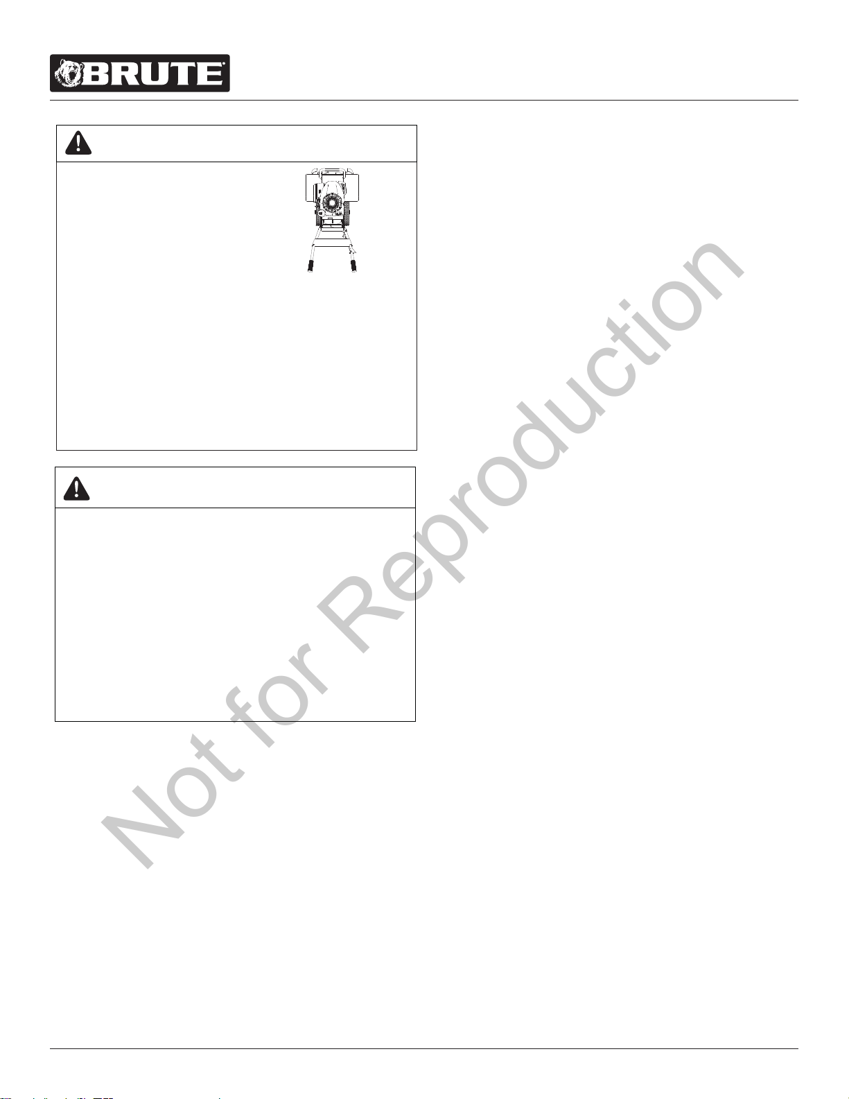
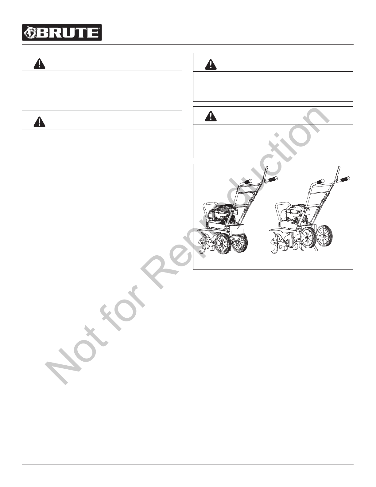
THE RIGHT AND LEFT SIDES
OF YOUR ROTOTILLER ARE
DETERMINED FROM THE
OPERATING POSITION AS
YOU FACE THE DIRECTION OF
FORWARD TRAVEL.
ENGINE IS SHIPPED FROM FACTORY WITHOUT OIL.
YOU MUST ADD ENGINE OIL BEFORE STARTING
ENGINE.
THIS IS A MOTORIZED ROTARY TILLER THAT
WORKS THE SOIL BY MEANS OF ROTATING TINES.
IT IS PEDESTRIAN CONTROLLED, BUT NOT SELF
PROPELLED, WITH A GASOLINEFUELED INTERNAL
COMBUSTION ENGINE TO POWER THE TINES. IT
SHALL NOT BE USED FOR ANY OTHER PURPOSE.
WARNING
HOT GASES ARE A NORMAL BYPRODUCT OF A
FUNCTIONING INTERNAL COMBUSTION ENGINE.
FOLLOW ALL SAFETY INSTRUCTIONS TO PREVENT
BURNS AND FIRES.
DO NOT ALTER/MODIFY ENGINE:
NEVER ALTER OR MODIFY THE ENGINE FROM
THE FACTORY. SERIOUS INJURY OR DEATH MAY
OCCUR IF ENGINE IS MODIFIED OR ALTERED.
WHEN WORKING ON OR REPLACING PARTS FOR
THE ENGINE OR PRODUCT, YOU MUST ALWAYS
FLIP THE ON/OFF SWITCH TO THE OFF POSITION.
WARNING
L R
Not for Reproduction
For additional information visit online at www.brutepower.com or call 800-743-4115 M-F 8-5 CST
Operator’s Manual
Front Tine Tiller
7
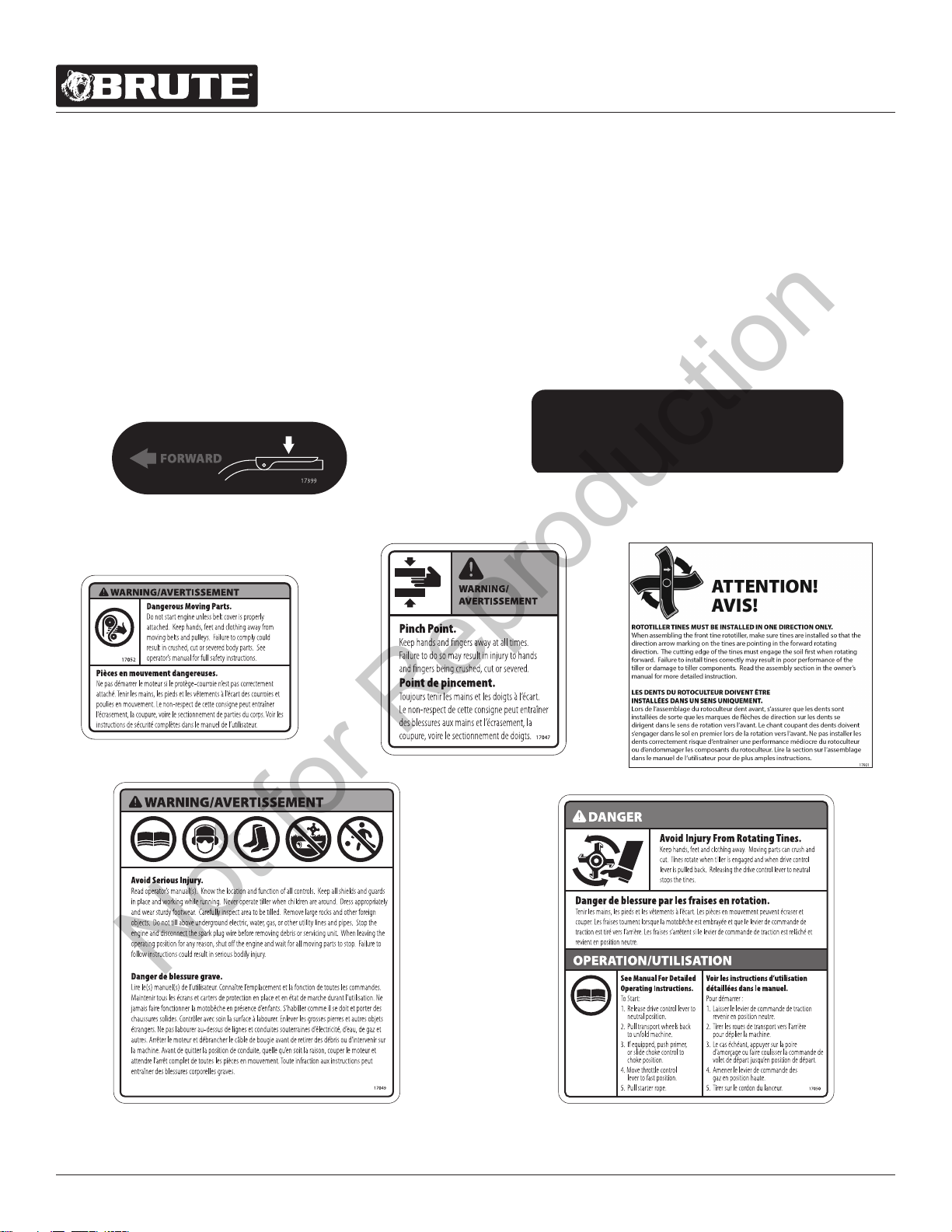
Part No. 17047
PINCH POINT WARNING
Tail Mount Decal
Part No. 17052
MOVING PARTS WARNING
Frame Near Belt Decal
Part No. 17050
TINES DANGER/OPERATION
Hood Decal
Part No. 17049
MULTI INJURY WARNING
Hood Decal
SAFETY DECALS
This rototiller unit has been designed and manufactured to provide you with the safety and reliability you would expect from an
industry leader in outdoor power equipment manufacturing.
Although reading this manual and the safety instructions it contains will provide you with the necessary basic knowledge to
operate this equipment safely and eectively, we have placed several safety labels on the tiller to remind you of this important
information while you are operating the unit.
These important safety labels are illustrated below, and are shown here to help familiarize you with the location and content of
the safety messages you will see as you perform normal tilling operations. Please review these decals now, and if you have any
questions regarding its meaning or how to comply with these instructions, reread the complete safety instruction text in this man-
ual. For additional questions call Brute®Customer Service.
Part No. 17399
DECAL LEVER CLUTCH ENGAGEMENT
FWD YELLOW
When starting engine,
place free hand here.
Pour démarrer le moteur,
placer le main libre ici.
17918
Part No. 17918
DECAL PLACE FREE HAND HERE
Left Handle Bar
Part No. 17921
HANG TAG
Correct Tine Installation
Not for Reproduction
For additional information visit online at www.brutepower.com or call 800-743-4115 M-F 8-5 CST
Operator’s Manual
Front Tine Tiller
8
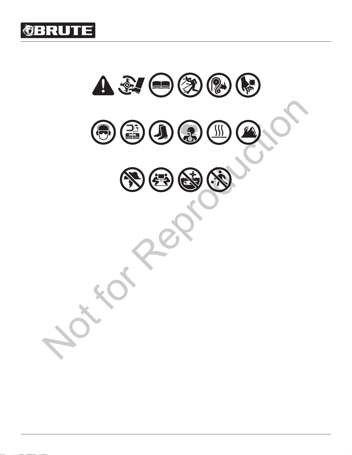
HAZARD SYMBOLS AND MEANINGS
A: Warning!
B: Avoid Injury From Rotating Tines.
C: Read Owner’s Manual Before Operating Machine.
D: Remove Objects that Could Be Thrown By This Machine.
E: Dangerous Moving Parts.
F: Be Aware of Moving and Rotating Parts.
G: Wear Ear and Eye Protection At All Times.
H: Do Not Service or Adjust Moving Parts Unless Engine is Stopped and Spark Plug
Wire is Disconnected.
I: Dress Appropriately And Wear Sturdy Footwear.
J: Toxic Fumes —Do Not Operate in Unventilated Areas.
K: Hot Surfaces.
L: Fire Hazards.
M. Do Not Use In Thunderstorms--For severe weather, stop operation of this
machine and seek shelter.
N. Team Lift--For your safety, always have at least two people when lifting this
machine.
O. Do Not Till Above Underground Utility Lines And Pipes.
P. Do Not Operate When Children Or Others Are Around.
A
B
C
D E F
G H
I
J
K
L
M
N
O P
Not for Reproduction
For additional information visit online at www.brutepower.com or call 800-743-4115 M-F 8-5 CST
Operator’s Manual
Front Tine Tiller
9
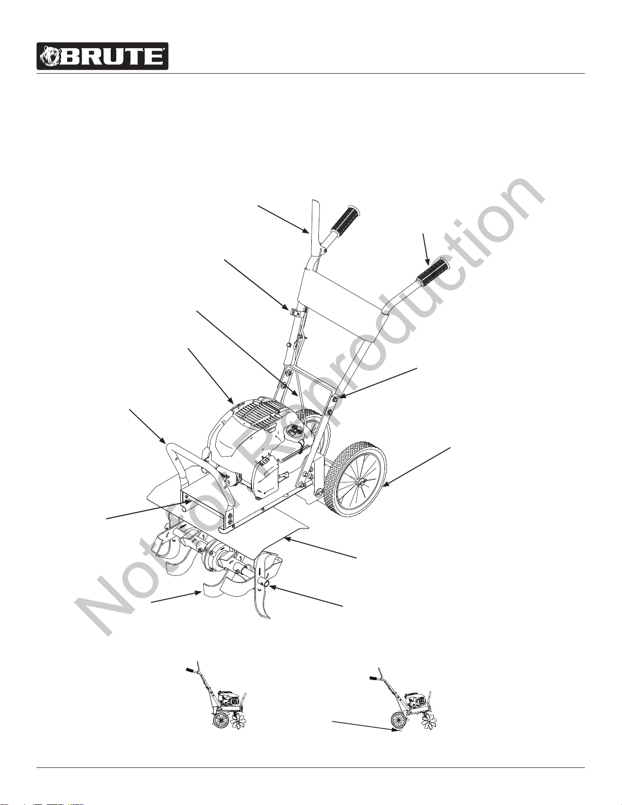
FEATURES
The advantage of the Brute® gear drive front tine rototiller, over other front tine tillers, is the exclusive
hinged tail mount, wheel and drag stake assembly. This feature gives the tiller its stability and versatility.
For easy transport and quick turning in the garden, fold the wheels under the engine. During operation, the
wheels unfold back and the drag stake folds down. The long length between the tines and the drag stake
make this the most comfortable handling front tine tiller on the market. SEE FIGURE 1
FIGURE 1
DRIVE SAFETY
CONTROL LEVER
KNOBBY COMFORT GRIPS
ADJUSTABLE
FORWARD
CABLE
BRIGGS & STRATTON
ENGINE
BUMPER
FRONT BELT
COVER
DURABLE
FORGED
TINES
3-WAY
ADJUSTABLE
TINE WIDTHS
3-POSITION HANDLE BAR
HEIGHT ADJUSTMENT
TINE SHIELD
LARGE 2-POSITION
WHEELS
TRANSPORT POSITION
OPERATING POSITION
DRIVE SAFETY
CONTROL LEVER
KNOBBY
COMFORT
GRIPS
3-POSITION
HANDLE
BAR HEIGHT
ADJUSTMENT
LARGE 2-POSITION
WHEELS
ADJUSTABLE DRAG STAKE
TINE SHIELD
3-WAY ADJUSTABLE
TINE WIDTHS
ADJUSTABLE
FORWARD
CABLE
KOHLER
ENGINE
BUMPER
FRONT
BELT
COVER
HINGED CAST-IRON TAIL MOUNT
DURABLE FORGED TINES
ON/OFF
SWITCH
Not for Reproduction
For additional information visit online at www.brutepower.com or call 800-743-4115 M-F 8-5 CST
Operator’s Manual
Front Tine Tiller
10
DO NOT LIFT ROTOTILLER FROM CARTON. ROTOTILLER
IS HEAVY AND CAN CAUSE INJURY. CUT BOX AWAY
FROM ROTOTILLER TO ACCESS MACHINE AND PARTS.
WARNING
UNPACKING AND ASSEMBLY
Carton Contents
• Front Tine Rototiller
• Parts Bag (with manuals and assembly hardware parts
packet)
• Parts Box (with outer tines, wheel axle, and drag stake)
• 2x Wheels
• Handlebar Assembly
• Tine Shield
Tools Required for Assembly
• Utility knife or box cutter
• 2x 10 mm Wrench
• 2x 12 mm Wrench
NOTE: Socket head wrench may make assembly
easier, but is not necessary.
ASSEMBLY
1. a. Open top of carton and remove handlebar assembly,
wheels, parts bag and tine shield.
b. Parts Packet contains:
• 4 - Bolts M8 X 1.25 X 20MM
• 2 - Hairpin 2.5 Dia. X 35MM
• 1 - Pin Lock 8 X 40mm
• 4 - Washers M8 8.4 X 24 X 2.2MM
• 2 - Bolts M8 X 1.25 X 45
• 6 - Nut M8 Nylock
• 2 - Washer 12MM
• 4 - Bolts M6 X 1.0 X 16 MM
• 4 - Nut M6 Nylock
NOTE: Plastic side of Nylock nut must face away
from bolt head during assembly. SEE FIGURE 8
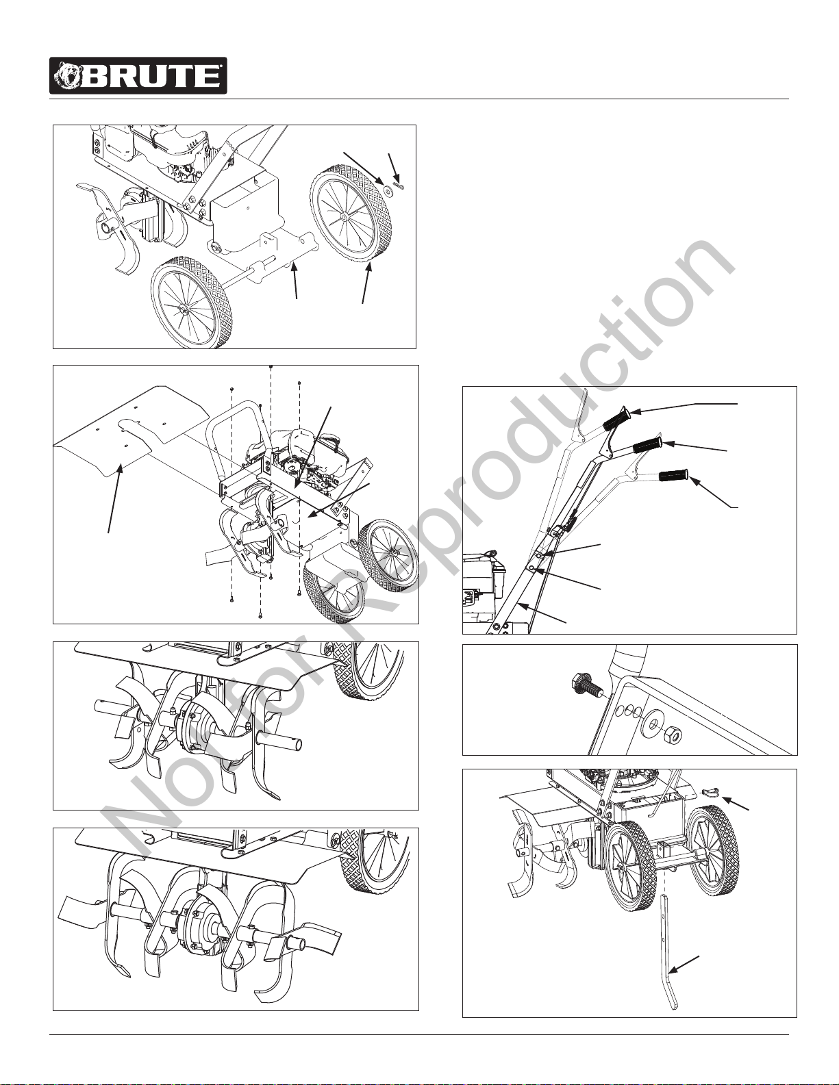
2. Cut all four corners of box so it lies at on the ground.
3. Pull out parts box and remove contents.
4. Assemble axle to lower tail mount. Install wheels on each
end of axle; install 12 MM washers onto axle against
wheels; insert hairpins into holes in axle to keep washers
and wheels in place. SEE FIGURE 3
HANDLE ROTOTILLER WITH CARE. DO NOT DAMAGE
THROTTLE CABLE WHEN TRANSPORTING OR
OPERATING.
CAUTION
5. Install tine shield using four M6 bolts and four M6 nylock
nuts. Line up slots on both sides of shield and insert
both bolts and nuts in place before fully tightening. SEE
FIGURE 4
NOTE: Dirt shield must be between engine mount
deck and tine shield.
6. Assemble tines to unit.
a. Assemble outer tines to unit using two M8 bolts and
two M8 nylock nuts. The arrow on the tines must
point toward the front of the machine. The sharp
edge of the tine will be away from operator at top, or
face down at front of machine.
b. Outside tines have two positions- wide 21” and
narrow 16”. For narrow width, assemble with short
side of tine holder pipe towards center of machine.
SEE FIGURE 5
c. For wide width, move the left tine to the right side
and right tine to the left side. Assemble with the long
half of tine pipe towards machine. SEE FIGURE 6
KEEP HANDS AND FEET AWAY FROM TAIL MOUNT
CASTING. FAILURE TO DO SO MAY RESULT IN SERIOUS
INJURY. SEE FIGURE 2
WARNING
IT IS RECOMMENDED THAT TWO PEOPLE ASSEMBLE
ROTOTILLER TOGETHER. ASSEMBLING ROTOTILLER
ALONE MAY MAKE ASSEMBLY MORE DIFFICULT AND
INCREASE RISK OF INJURY.
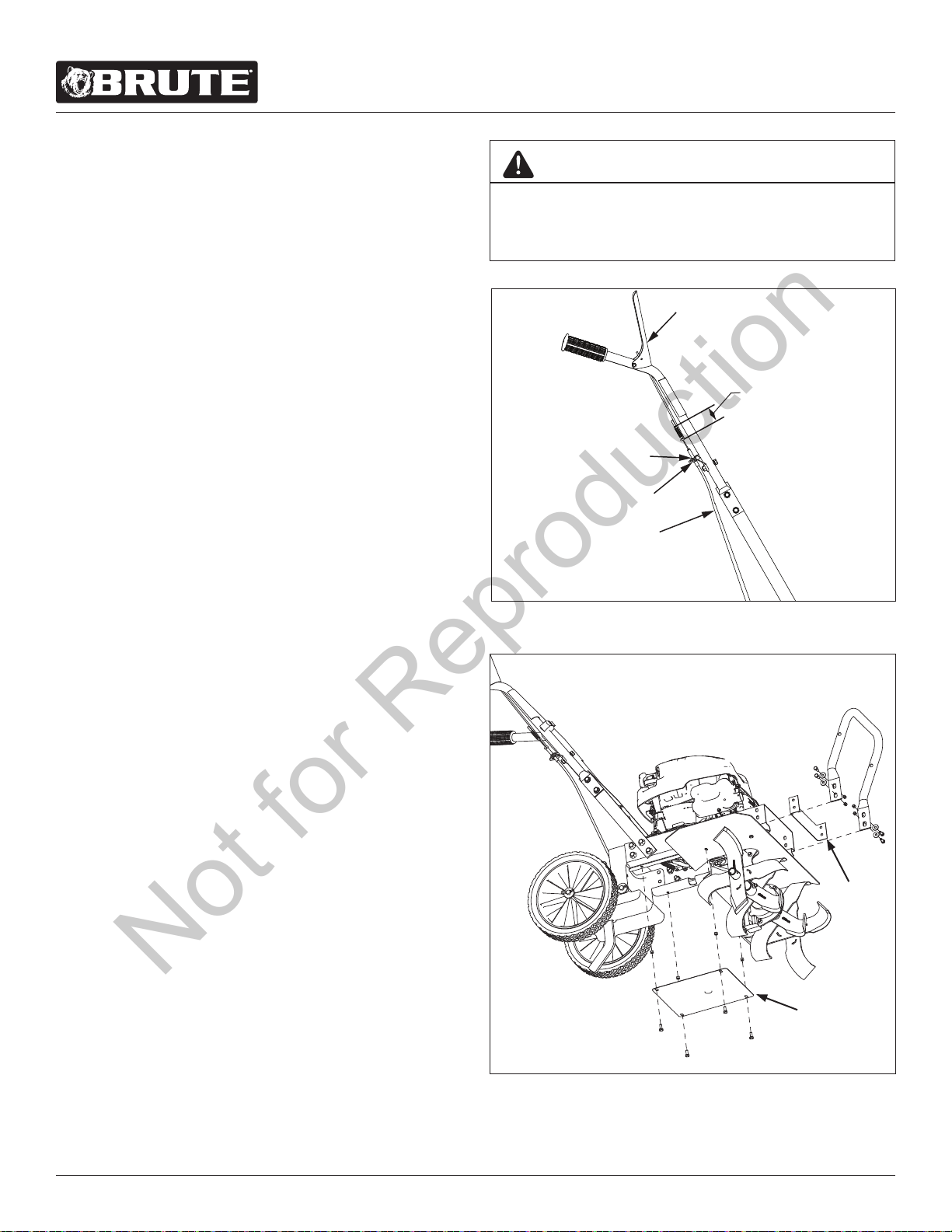
IMPORTANT
FIGURE 2
Tail mount casting allows tiller to be in two dierent positions:
working and transport. When transitioning from working
position into transport position, or vice versa, be careful of the
breach between the upper and lower tail mount casting to avoid
pinching hazards.
Transport Position
Working Position
Not for Reproduction
For additional information visit online at www.brutepower.com or call 800-743-4115 M-F 8-5 CST
Operator’s Manual
Front Tine Tiller
11
FIGURE 4
Dirt
Shield
Tine Shield
FIGURE 5
Narrow Tine Width
FIGURE 6
Wide Tine Width
7. a. Assemble the upper handle bar assembly onto the
lower loop mount using four M8 bolts, four M8 at
washers and four M8 locknuts. The handlebar as well
as the bolt should go on the outer side of the lower
loop mount, while the washer and nut should be
placed on the inside. SEE FIGURES 7 & 8
b. The upper two bolts can be assembled through
one of three hole positions depending on the user’s
preferred handle bar height (low, medium, high). For
the highest height, insert bolt into the most forward
hole. For the lowest height, insert bolt into the most
rear hole. SEE FIGURE 7
8. Insert depth regulator/drag stake through bottom
opening in lower tail mount and secure with lock pin.
SEE FIGURE 9
Lock Pin
Engine
Mount Deck
FIGURE 8
Nylock
Nut
Drag Stake
FIGURE 9
High
Position
Medium
Position
Low
Position
Upper Bolt
Lower Bolt
Lower Loop Mount
FIGURE 7
FIGURE 3
Lower Tail
Mount
Washer
Wheel
Hairpin
Not for Reproduction
For additional information visit online at www.brutepower.com or call 800-743-4115 M-F 8-5 CST
Operator’s Manual
Front Tine Tiller
12
Fill Engine Crankcase
1. Add oil according to engine manual. Do not overll.
Use a clean, high quality detergent oil. Use no special
additives with recommended oils. Do not mix oil with
gasoline. Oil level must be full. Check the oil level by
checking the engine’s oil dipstick if provided, or by
removing oil ll plug. Oil level should be up to the
bottom of the ll plug opening.
2. Always check oil level before starting engine. Refer to
engine manual for capacity and type of oil to use.
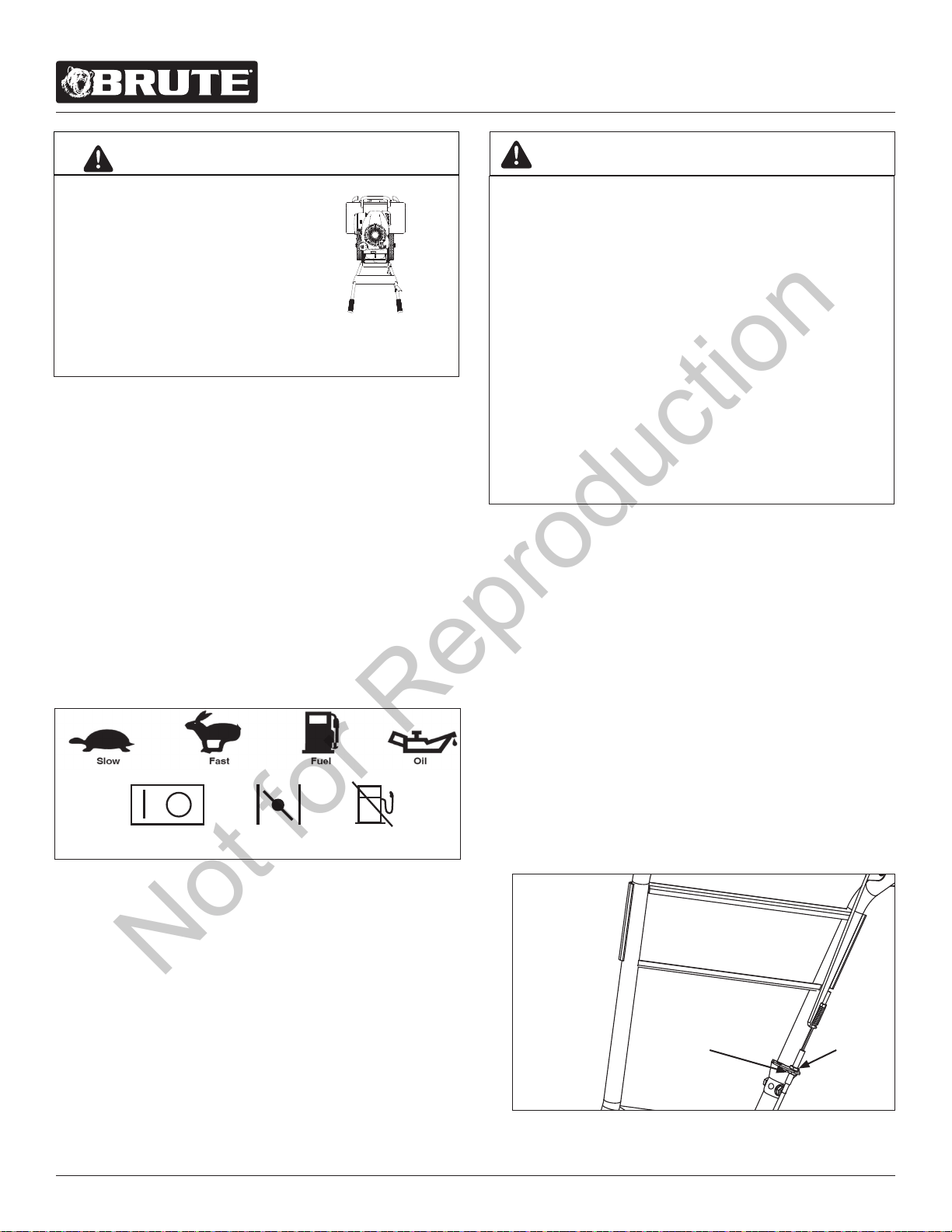
CONTROL AND OPERATING SYMBOLS
FIGURE 10 shows common control and operating symbols
that may be found on the unit or in this manual. Before you
operate your unit, learn and understand the purpose for each
symbol.
Choke
On/O Fuel Shuto
CONTROLS
Drive Safety Control Lever
Pulling down on the drive safety control lever engages the
tines. Releasing the drive safety control lever disengages the
tines to a neutral position.
Belt Tension Adjustment
Proper belt tension is critical for good performance. After 30
minutes of operation, all cables may have to be adjusted due
to initial stretch. Thereafter, check tension after every two
hours of operation.
THIS INFORMATION IS PROVIDED HERE ONLY TO
INTRODUCE THE CONTROLS. DO NOT START THE
ENGINE AT THIS TIME. STARTING AND OPERATING
INSTRUCTIONS ARE GIVEN IN THIS MANUAL. PLEASE
READ THIS SECTION AND ALL OPERATING AND
SAFETY INSTRUCTIONS BEFORE STARTING YOUR
TILLER.
• AS A SAFETY PRECAUTION, THE DRIVE SAFETY
CONTROL LEVER WILL NOT LOCK IN THE FORWARD
POSITION.
• TO STOP THE TINES AT ANY TIME, RELEASE THE
DRIVE SAFETY CONTROL LEVER.
• ENGINE SHOULD BE OFF BEFORE ADJUSTING
ANY CONTROLS.
• DO NOT ADJUST TILLING DEPTH UNLESS DRIVE
SAFETY CONTROL LEVER IS RELEASED TO THE
NEUTRAL POSITION.
WARNING
THE RIGHT AND LEFT SIDES
OF YOUR ROTOTILLER ARE
DETERMINED FROM THE
OPERATING POSITION AS
YOU FACE THE DIRECTION OF
FORWARD TRAVEL.
ENGINE IS SHIPPED FROM FACTORY WITHOUT OIL.
YOU MUST ADD ENGINE OIL BEFORE STARTING
ENGINE.
WARNING
FIGURE 10
1. To increase belt tension, loosen upper jam nut in1/8”
increments while holding lower jam nut in place.
SEE FIGURE 11
2. Check adjustment and instructions under “Check Belt
Tension” section.
This procedure can be repeated until conduit adjustment
bolts have no more adjustment left. If no more adjustment
can be made, belt may have to be replaced.
Depth Regulator Drag Stake
To Adjust Tilling Depth:
1. Remove lock pin.
2. Raise or lower the depth regulator. The lower the depth
regulator, the deeper the tilling depth.
3. Align hole in depth regulator lever with hole in depth
regulator bracket and replace lock pin.
SEE FIGURE 9 (page 11)
L R
UPPER
JAM
NUT
LOWER
JAM
NUT
FIGURE 11
Not for Reproduction
For additional information visit online at www.brutepower.com or call 800-743-4115 M-F 8-5 CST
Operator’s Manual
Front Tine Tiller
13
• DO NOT START YOUR TILLER UNTIL YOU HAVE
READ AND UNDERSTAND THIS MANUAL AND THE
SECTIONS IN THIS MANUAL COVERING SAFETY
AND OPERATION. ONCE YOU HAVE READ THE
MANUAL, FOLLOW THE APPROPRIATE STEPS
TO START YOUR TILLER. ALWAYS PERFORM THE
PRESTART CHECKLIST BEFORE STARTING THE
ENGINE.
• PRACTICE OPERATING THE CONTROLS AND
TILLER WITH TINES OUT OF GROUND BEFORE
BEGINNING TO TILL. IT IS IMPORTANT THAT YOU
KNOW HOW TO USE THE TILLER PROPERLY, KEEP
CONTROL AT ALL TIMES, STOP THE TINES AND
WHEELS FROM TURNING, AND STOP THE ENGINE
IF NECESSARY. IF YOU DO NOT KNOW HOW TO
DO THESE THINGS, READ THE CONTROLS AND
SAFETY SECTIONS BEFORE PROCEEDING.
• TEMPERATURE OF MUFFLER AND NEARBY AREAS
MAY EXCEED 150° F. AVOID THESE AREAS.
• EXTREME CAUTION MUST BE TAKEN IN
SELECTING TILLING DEPTH. IF YOU ATTEMPT TO
TILL IN CERTAIN SOIL CONDITIONS WITH THE
DRAG STAKE IN TOO HIGH OF A POSITIONLOSS
OF CONTROL COULD RESULT.
• IF REMOVING MATERIAL FROM THE TINES BY
HAND, STOP THE ENGINE AND REMOVE SPARK
PLUG WIRE FIRST.
• FAILURE TO FOLLOW INSTRUCTIONS CAN CAUSE
DAMAGE TO PROPERTY OR PERSONAL INJURY.
WARNING
• TO STOP THE ENGINE AT ANY TIME, MOVE
THROTTLE CONTROL TO THE OFF OR STOP
POSITION, OR FLIP THE ON/OFF SWITCH TO OFF.
• TO STOP TINES AT ANY TIME, RELEASE DRIVE
SAFETY CONTROL LEVER TO THE NEUTRAL
POSITION.
• ALWAYS RELEASE DRIVE SAFETY CONTROL LEVER
TO THE NEUTRAL POSITION BEFORE ADJUSTING
THE DEPTH OF THE DRAG STAKE.
• ALWAYS MAINTAIN CONTROL OF YOUR TILLER.
ONLY OPERATE TILLER IN SOIL CONDITIONS THAT
ARE CONDUCIVE TO MAINTAINING CONTROL
OF THE TILLER. DO NOT OPERATE TILLER IN
CONDITIONS THAT CONTAIN ROCKS, FOREIGN
OBJECTS, OR ANY OTHER MATERIAL THAT IS NOT
SOIL. IF YOUR TILLER BUMPS, JERKS OR LURCHES,
LET GO OF THE HANDLE BARS AND THE DRIVE
CONTROL LEVER IMMEDIATELY SO THAT THE
TINES STOP TURNING.
• ENGINE AND SURROUNDING PARTS BECOME
EXTREMELY HOT DURING NORMAL USE AND WILL
CAUSE SERIOUS BURN INJURIES IF TOUCHED
BEFORE THE ENGINE HAS COOLED.
• ALLOW ENGINE TO COOL COMPLETELY BEFORE
TOUCHING THESE HOT SURFACES.
• ALWAYS KEEP HANDS AND FEET CLEAR OF
ROTATING MACHINE PARTS.
• FAILURE TO FOLLOW INSTRUCTIONS CAN CAUSE
DAMAGE TO PROPERTY OR PERSONAL INJURY.
WARNING
• ENGINE IS SHIPPED FROM FACTORY WITHOUT
OIL. YOU MUST ADD ENGINE OIL BEFORE
STARTING ENGINE.
• FAILURE TO FOLLOW INSTRUCTIONS CAN CAUSE
DAMAGE TO EQUIPMENT.
CAUTION
Not for Reproduction
For additional information visit online at www.brutepower.com or call 800-743-4115 M-F 8-5 CST
Operator’s Manual
Front Tine Tiller
14
Cold Start
1. Push ON/OFF switch to the ON position.
2. Pull starting rope out slowly one time and allow to return
normally.
3. Pull starting rope out rapidly and allow rope to return
normally.
NOTE: The Briggs & Stratton engine installed on this
tiller is equipped with the ReadyStart® Starting
System. The engine is xed speed and has an
auto-choke.
Restarting A Warm Engine
1. Push ON/OFF switch to the ON position.
2. Pull starting rope out rapidly until engine starts. Allow
rope to return normally. Repeat until engine starts.
Shutting Down
To stop the engine at any time, put the ON/OFF switch to the
OFF position. To stop tines at any time, release the drive safety
control to the neutral position.
Tilling
1. Adjust the depth regulator drag stake to achieve desired
tilling depth.
NOTE: Raise depth regulator lever up one hole at
a time, testing tiller operation after each
adjustment. Raising depth regulator lever too
high can result in loss of control of tiller!
2. Place the tiller in motion by pushing down on the drive
safety control lever; this will engage the tines.
OPERATION
Pre-Start Inspection
1. Make sure all safety guards are in place and all nuts and
bolts are secure.
NOTE: All hardware (nuts, bolts, etc) should be checked
for tightness before each use. Vibration of machine
can cause them to loosen.
2. Check oil level in engine crankcase. See your engine
manual for procedure and specications.
3. Inspect air cleaner for cleanliness. See your engine
manual for procedure.
4. Check the fuel level. Fill the fuel tank no closer than one
inch from top of tank to provide space for expansion. See
your engine manual for fuel recommendations.
5. Be sure spark plug wire is attached and spark plug is
tightened securely.
6. Check position of wheels.
7. Check depth regulator drag stake position.
8. Examine underneath and around engine for signs of oil or
fuel leaks.
9. Inspect fuel hoses for tightness and fuel seepage.
10. Look for signs of engine damage.
11. Remove excessive debris from muer area and recoil
starter.
12. Turn fuel shuto valve to the ON position if engine is
equipped with one.
STARTUP
The ON/OFF switch is required to cold start the rototiller is
located on the handlebar and is marked with an ON/OFF
symbols (See Operation Control Symbols in the Controls and
Operating Symbols section of this manual). SEE FIGURE 12
A description of engine operation and all related precautions
and procedures can be found in the engine manufacturer’s
manual that accompanies the tiller.
GASOLINE IS HIGHLY FLAMMABLE AND MUST BE
HANDLED WITH CARE. NEVER FILL THE TANK WHEN
THE ENGINE IS HOT OR RUNNING. ALWAYS MOVE
OUTDOORS TO FILL THE TANK.
WARNING
ON/OFF
SWITCH
Not for Reproduction
For additional information visit online at www.brutepower.com or call 800-743-4115 M-F 8-5 CST
Operator’s Manual
Front Tine Tiller
15
MAINTENANCE
Maintenance Schedule
Your rototiller has been designed and produced by the industry’s leading manufacturer of outdoor power equipment to provide
you with years of reliable operation. Keeping your tiller in top running condition will prolong its life, and help you obtain optimum
performance. Please read this maintenance schedule, and note the recommended care operating intervals to extend the life of
your unit.
Maintenance Operation Page
Before
Each Use
50 hours or
Every Season
Check belt tension 16 X
Change forward belt 16 X
Engine maintenance 17, EM X X
Check oil level/Add oil 17, EM X X
Clean tine axle shaft 17 X X
Lubrication 17 X
EM = See engine manual
SERVICING THE ROTOTILLER
The following information will help you make the necessary
checks and perform the procedures required to follow the
normal care recommendations made for your rototiller unit.
If you prefer, your local authorized dealer can make these
checks and perform the required procedures for you.
Important: Use only approved Brute® spare parts.
PREVENT ACCIDENTAL STARTING.
ENGINE MUST BE TURNED OFF AND COOL, AND SPARK
PLUG WIRE MUST BE REMOVED AND SECURED FROM
SPARK PLUG BEFORE CHECKING AND ADJUSTING
ENGINE OR EQUIPMENT. ACCIDENTAL ENGINE START
CAN CAUSE SERIOUS INJURY.
WARNING
Spark Plug Wire
Not for Reproduction
For additional information visit online at www.brutepower.com or call 800-743-4115 M-F 8-5 CST
Operator’s Manual
Front Tine Tiller
16
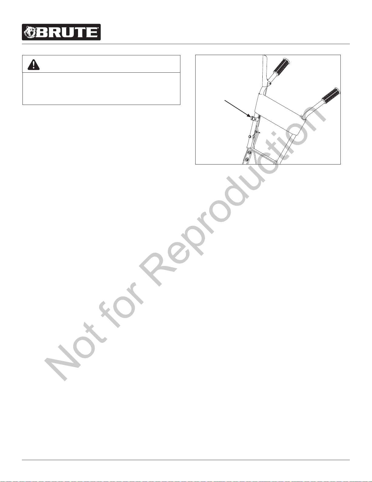
BELT MAINTENANCE
Check Belt Tension
Belt tension may decrease over time. It may need to be ad-
justed within the rst half hour of operation and should be
checked after every two hours of operation. Proper adjustment
will assure long belt life. Too much or too little belt tension will
cause premature belt failure.
An indication that the belt may need to be adjusted is a con-
stant buzzing sound that can be heard when the engagement
lever is compressed (see page 18), or a persistant squealing
sound when engaged and under load.
NOTE: A short buzzing noise can be heard when engage-
ment lever is released. This is normal, caused by the
teeth of the cog belt catching the wire guide, stopping
the rotation of the belt. This does not require the belt
tension to be adjusted.
To check and adjust the belt tension, do as follows:
1. Turn o engine. Engine must be cool.
2. Remove spark plug wire from spark plug and secure.
3. With drive safety control lever in the neutral position,
measure length of the cable link compression spring
when in its relaxed state.
4. Pull down on drive safety control lever and measure
length of spring when compressed. Ideal length would
be 1/4” shorter. SEE FIGURE 13
Change Belt
1. Turn o engine. Engine must be cool.
2. Remove spark plug wire from spark plug and secure.
3. Remove front belt cover and dirt shield plate from tiller
frame. SEE FIGURE 14
a. Remove the belt from the engine pulley as follows:
• Gently pull the engine recoil rope to rotate the
pulley.
• With the pulley turning, force the belt out of the
V-groove.
• Slide the belt free of the engine pulley.
• Pull the belt down and out of the way.
• Push the belt forward and out the front of the
machine.
b. Install new belt as follows:
• Place belt in transmission pulley groove.
• Gently pull the engine recoil rope to rotate the
engine pulley while forcing the belt into the
V-groove.
4. Reinstall front belt cover and dirt shield plate onto tiller
frame.
5. Check and readjust belt tension if necessary.
6. Attach spark plug wire.
BELT REPLACEMENT P/N: 22633
CHECK BELT TENSION REGULARLY. TOO MUCH OR
TOO LITTLE TENSION WILL CAUSE PREMATURE BELT
FAILURE AND DAMAGE TO EQUIPMENT.
IMPORTANT
FIGURE 14
FRONT
BELT
COVER
DIRT
SHIELD
PLATE
1/4” STRETCH
UPPER JAM NUT
LOWER JAM NUT
FORWARD CABLE
DRIVE SAFETY CONTROL
LEVER DISENGAGED
FIGURE 13
Not for Reproduction
For additional information visit online at www.brutepower.com or call 800-743-4115 M-F 8-5 CST
Operator’s Manual
Front Tine Tiller
17
ENGINE MAINTENANCE
Refer to the engine manual included in your parts bag for
information on engine maintenance. Your engine manual pro-
vides information and a maintenance schedule for performing
the following tasks:
1. Check oil level before each use and after every eight
hours of operation.
CAUTION
• ENGINE IS SHIPPED FROM FACTORY WITHOUT
OIL. YOU MUST ADD ENGINE OIL BEFORE
STARTING ENGINE.
• ENGINE CAN OVERHEAT AND BECOME DAMAGED
IF DEBRIS BLOCKS THE COOLING SYSTEM OR
ROTATING SCREEN.
• NEVER RUN ENGINE WITHOUT COMPLETE AIR
CLEANER INSTALLED ON ENGINE.
• FAILURE TO FOLLOW THESE INSTRUCTIONS CAN
CAUSE DAMAGE TO THE ENGINE AND VOID YOUR
WARRANTY.
2. Check spark plug yearly or every 100 hours of operation.
3. Service air cleaner.
4. Keep engine and parts clean.
5. Check engine and equipment often for loose nuts and
bolts; keep all hardware tightened.
Check or Fill Engine Crankcase
1. Add oil according to engine manual. Do not overll. Use
a clean, high-quality 4-cycle engine oil. Use no special
additives with recommended oils. Do not mix oil with
gasoline. Oil level must be full. Check the oil level by
checking the engine’s oil dipstick.
2. Always check oil level before starting engine. Refer to
engine manual for capacity and type of oil to use.
Clean Tine Axle Shaft
1. Turn o engine. Engine must be cool.
2. Remove spark plug wire and secure from spark plug.
3. Remove all vegetation, string, wire, and other material
that may have accumulated on the axle between the
inside set of tines and the seal on the transmission
housing.
4. Replace spark plug wire.
Lubrication
Proper lubrication of moving mechanical parts is critical for
proper care and maintenance. Oil the moving parts using a
30-weight oil.
DO NOT STORE TILLER IN AN UNVENTILATED AREA
WHERE FUEL FUMES MAY REACH FLAME, SPARKS,
PILOT LIGHTS OR AN IGNITED OBJECT. DRAIN FUEL
OUTDOORS AWAY FROM ANY IGNITION SOURCES.
USE ONLY APPROVED FUEL CONTAINERS.
WARNING
STORAGE
Prepare for Storage
Follow the steps below to prepare your tiller for storage. Read
your engine manual for detailed instructions on preparing the
engine for storage.
1. Protect wheels and axles from rust:
• Coat the axles lightly with axle grease.
2. Drain fuel system completely following engine manufacturer’s
instructions or add fuel stabilizer to prevent fuel from
gumming up during extended storage period. Run engine
for at least 5 minutes to distribute fuel stabilizer mixture
throughout entire fuel system.
3. Clean external surfaces, engine and cooling fan.
4. Remove spark plug; pour one ounce of SAE 30 oil into spark
plug hole.
5. Plug hole and pull starter cord slowly to distribute oil evenly
in cylinder head area.
6. Reinstall spark plug.
7. Transport unit to a suitable storage location. If you have
chosen to use a fuel stabilizer and have not drained the fuel
system, follow all safety instructions and storage precautions
in this manual to prevent the possibility of re from the
ignition of gasoline fumes. Remember, gasoline fumes can
travel to distant sources of ignition and ignite, causing risk
of explosion and re.
8. If there is any possibility of unauthorized use or tampering,
remove the spark plug and store it in a safe place before
storing the rototiller unit. Be sure to plug the spark plug hole
to prevent foreign material from entering.
PRACTICE SAFETY AT ALL TIMES. ENGINE MUST BE
TURNED OFF AND ALLOWED TO COOL, AND SPARK
PLUG WIRE MUST BE DISCONNECTED AND SECURED
BEFORE ATTEMPTING ANY MAINTENANCE OR REPAIR.
FAILURE TO COMPLY WITH THIS SAFETY
REQUIREMENT CAN RESULT IN SERIOUS PERSONAL
INJURY TO YOU OR BYSTANDERS.
WARNING
Not for Reproduction

For additional information visit online at www.brutepower.com or call 800-743-4115 M-F 8-5 CST
Operator’s Manual
Front Tine Tiller
18
PROBLEM REMEDY/ACTION
Engine will not start • Add gas to gas tank.
• Connect spark plug wire to spark plug.
• ON/OFF switch must be turned ON.
Engine runs rough, oods during operation • Clean or replace air cleaner.
Engine is hard to start • Drain old fuel and replace with fresh. Use gas stabilizer at
end of season.
• Make sure spark plug wire is securely attached to spark
plug.
• Drive safety control lever must be released to neutral to
start the engine.
Engine misses or lacks power • Raise the tines for shallow tilling by raising the depth
regulator drag stake.
• Clean or replace air cleaner.
• Improper carburetor adjustment, take to authorized
engine service center.
• Replace spark plug and adjust gap.
• Drain and rell gas tank.
Tiller moves forward during starting • Drive safety control lever must be released to neutral to
start the engine.
Tiller is dicult to control when tilling
(Machine jumps or lurches forward)
• Lower the depth regulator drag stake for greater resis-
tance and control of the machine.
Belts squeal in forward operation • Turn engine o and allow muer to cool.
• Disconnect spark plug wire and secure from spark plug.
• Release drive safety control lever to neutral.
• Adjust engage cable.
• Replace spark plug wire.
Constant buzzing sound is heard while engagement lever is
compressed
• Fully compress engagment lever
• Properly space wire guide from idler pulley to clear belt
• Tighten throttle cable
NOTE: If engagement lever is fully compressed, wire
guide is properly adjusted, and cable has reached
full adjustment and buzzing persists, the belt may be
stretched and have to be replaced. *
Excessive heat build up in transmission/tine area during tilling • Remove vegetation.
• Check transmission uid and ll if needed.
TROUBLESHOOTING AND REPAIR
Troubleshooting Guide
While normal care and routine maintenance will extend the life of your rototiller, prolonged or constant use may eventually
require that service be performed to allow it to continue operating properly. The troubleshooting guide below lists the most com-
mon problems, causes and remedies.
* Please contact 800-345-6007 for service parts
Not for Reproduction

For additional information visit online at www.brutepower.com or call 800-743-4115 M-F 8-5 CST
Operator’s Manual
Front Tine Tiller
19
WARRANTY TERMS AND CONDITIONS
PRODUCT WARRANTY: 2YEAR LIMITED WARRANTY
BRUTE GARDEN TILLERS MANUFACTURED AFTER 09/01/2015
Ardisam, Inc. (Ardisam) warrants this garden tiller under a two-year limited warranty to be free from defects in the material
or workmanship or both for a period not exceeding 24 consecutive months from the date of original purchase by the rst
retail consumer or rst commercial end user. This warranty does not apply to the engine mounted on the product. “Consumer
use”, means personal recreational use by a retail consumer. “Commercial use“, or “commercial application“, means all other
uses, including use for commercial, income producing, or rental purposes. Once a product has experienced commercial use,
it shall thereafter be considered as a commercial use product for the purpose of this warranty. This warranty applies to the
original owner that provides a proof of purchase. This warranty is not transferable. The warranty period begins on the date of
purchase by the rst retail consumer or commercial end user and continues for the 24 month consecutive period thereafter.
Any unit used in a commercial application is covered for a period of 90 days after purchase by the rst commercial end user.
For the warranty to be valid, the product must be registered online within 30 days of purchase, or the warranty card must be
lled out and received by Ardisam within 30 days of purchase. Ardisam shall not be obligated for transportation charges that
result from repair or replacement under the terms of this warranty. Transportation charges are the sole responsibility of the
purchaser. This warranty excludes parts that are worn or damaged due to normal wear such as tines, belts, wheels, tires, seals,
bushings, gears, pulleys, grips, shafts, springs and cables. This warranty excludes routine maintenance items such as lter
elements, O-rings, seals, lubricants, and tune-ups. These warranties shall not cover damage caused by improper storage and
maintenance including but not limited to use of unauthorized parts, failure to perform periodic maintenance as specied in
product manual, or repairs performed at unauthorized service centers. These warranties apply only to products which have
not been subjected to negligent use, abuse, misuse, alteration or overload which includes but is not limited to running the
tiller dry (without oil), or below minimum oil levels, using the tiller for a purpose other than that for which it was designed
and manufactured, using the tiller in violation of local codes, ordinances and good trade practices, improper installation,
operating the equipment above recommended maximums as stated in this manual and the accompanying engine manual.
This warranty does not cover events beyond the control of Ardisam such as accident, acts of God, lightning, and vandalism.
This limited warranty applies only to defects in the material or workmanship. There is no other express warranty. Implied
warranties, including those of merchantability and tness for a particular purpose, are limited to one year from purchase, or
to the extent permitted by law. All other implied warranties are excluded. Liability for incidental or consequential damages
are excluded to the extent exclusion is permitted by law. Ardisam does not assume, and does not authorize any other person
to assume for Ardisam, any liability in connection with the sale of Ardisam products. To be at “No Charge,” warranty work
must be sent directly to and performed by Ardisam or an Ardisam Authorized Warranty Service Facility. To obtain warranty
service and/or replacement instructions, contact the Ardisam Customer Service Department at 800-345-6007. If you choose
to ship your product to Ardisam for warranty repair, you must rst have prior approval from Ardisam by calling the Ardisam
Customer Service Department for a return material authorization number (RMA#). Under these circumstances, all items must
be shipped prepaid. Ardisam will, in its discretion, at no charge, repair or replace any defective part to which this warranty
applies. Ardisam retains the right to change models, specications and price without notice. Ardisam shall not be obligated
to ship any repair or replacement product to any location outside of the United States of America or Canada. Some states and
countries do not allow the limitations on how long an implied warranty lasts, or the exclusion or limitation of incidental or
consequential damages, so the above limitation may not apply to you. This warranty gives you specic legal rights, and you
may also have other rights which vary from state to state and country to country.
SEE ENGINE MANUAL FOR ENGINE WARRANTY
Not for Reproduction
For additional information visit online at www.brutepower.com or call 800-743-4115 M-F 8-5 CST
Operator’s Manual
Front Tine Tiller
20
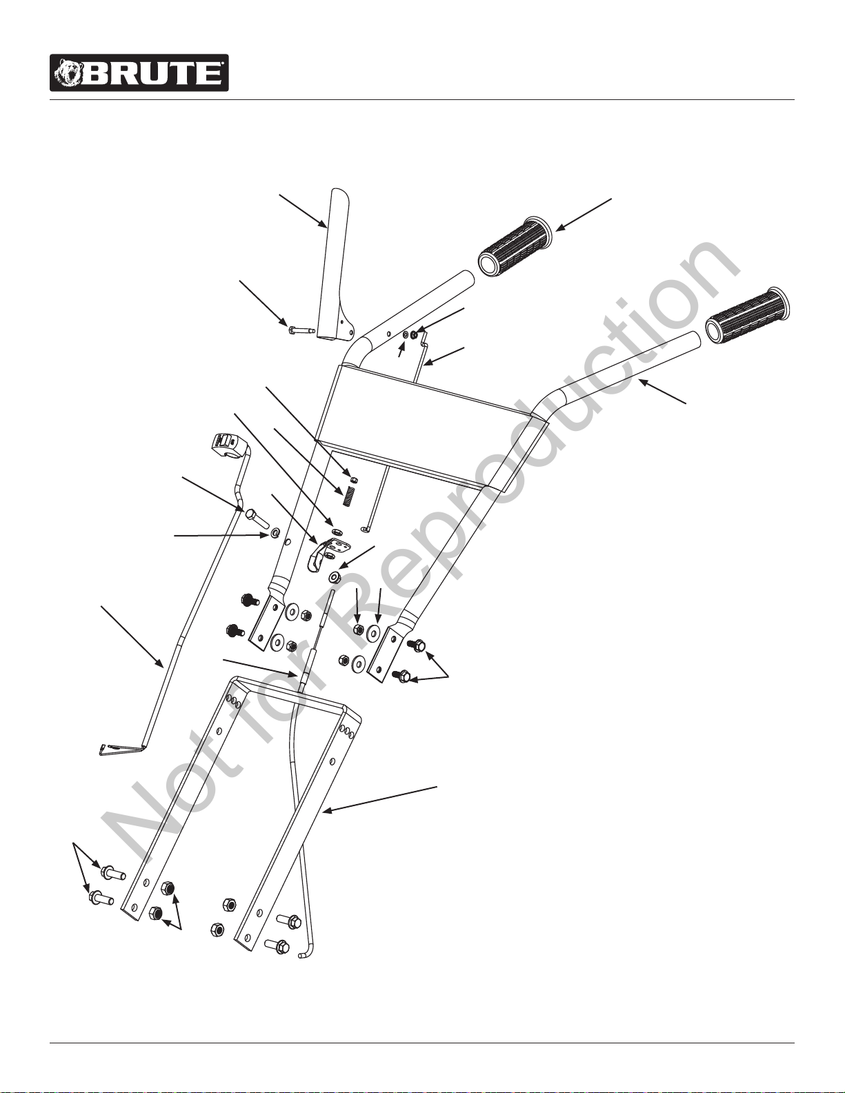
ILLUSTRATED PARTS BREAKDOWN: HANDLEBAR ASSEMBLY
6
7
3
4
5
1
2
8, 14
9
10, 14
13
12
11
17
1615
14
21
18
20
19
22
Not for Reproduction

For additional information visit online at www.brutepower.com or call 800-743-4115 M-F 8-5 CST
Operator’s Manual
Front Tine Tiller
21
ITEM
NO.
PART # DESCRIPTION QTY.
1 3248 NUT M5 X 0.8 NYLOCK 1
2 3308 WASHER FLAT M5 X 15 X 1.75 1
3 53650BLK LEVER, CONTROL 1
4 13159 BOLT M5 X 0.75 X 7 HEX
HEAD SHOULDER 6 X 32MM
1
5 20841 LINK 317 MM 1
6 13833 COMFORT GRIP 1 IN 2
7 23153 HANDLEBAR WELDMENT 1
8 IN58 NUT M5 X 0.8 NYLOCK 1
9 53620 SPRING, COMPRESSION FOR-
WARD ARM
1
10 4620 JAM NUT M8 X 1.25 2
11 53629 BRACKET, CABLE MOUNT 1
12 W1200114 WASHER M8 X 1.9 1
13 12770 BOLT M8 X 1.25 X 40 HEX
HEAD
1
ITEM
NO.
PART # DESCRIPTION QTY.
14 20827 KIT CABLE M5 END M8
MOUNT 905.5 MM lONG
1
15 400023 NUT M8 NYLOCK 4
16 3245 WASHER M8 X 24X 2.2MM 4
17 13906 BOLT M8 X 1.25 X 20 4
18 16982 MOUNT, HANDLEBAR 1
19
W1265V0903
NUT M10 X 1.5 NYLOCK 4
20 20819 BOLT M10 X 1.5 X 30 HEX
HEAD
4
21 13508 NUT M8 X 1.25 1
22 17471 SWITCH ASSEMBLY 1
ILLUSTRATED PARTS BREAKDOWN: HANDLEBAR ASSEMBLY
Not for Reproduction
For additional information visit online at www.brutepower.com or call 800-743-4115 M-F 8-5 CST
Operator’s Manual
Front Tine Tiller
22
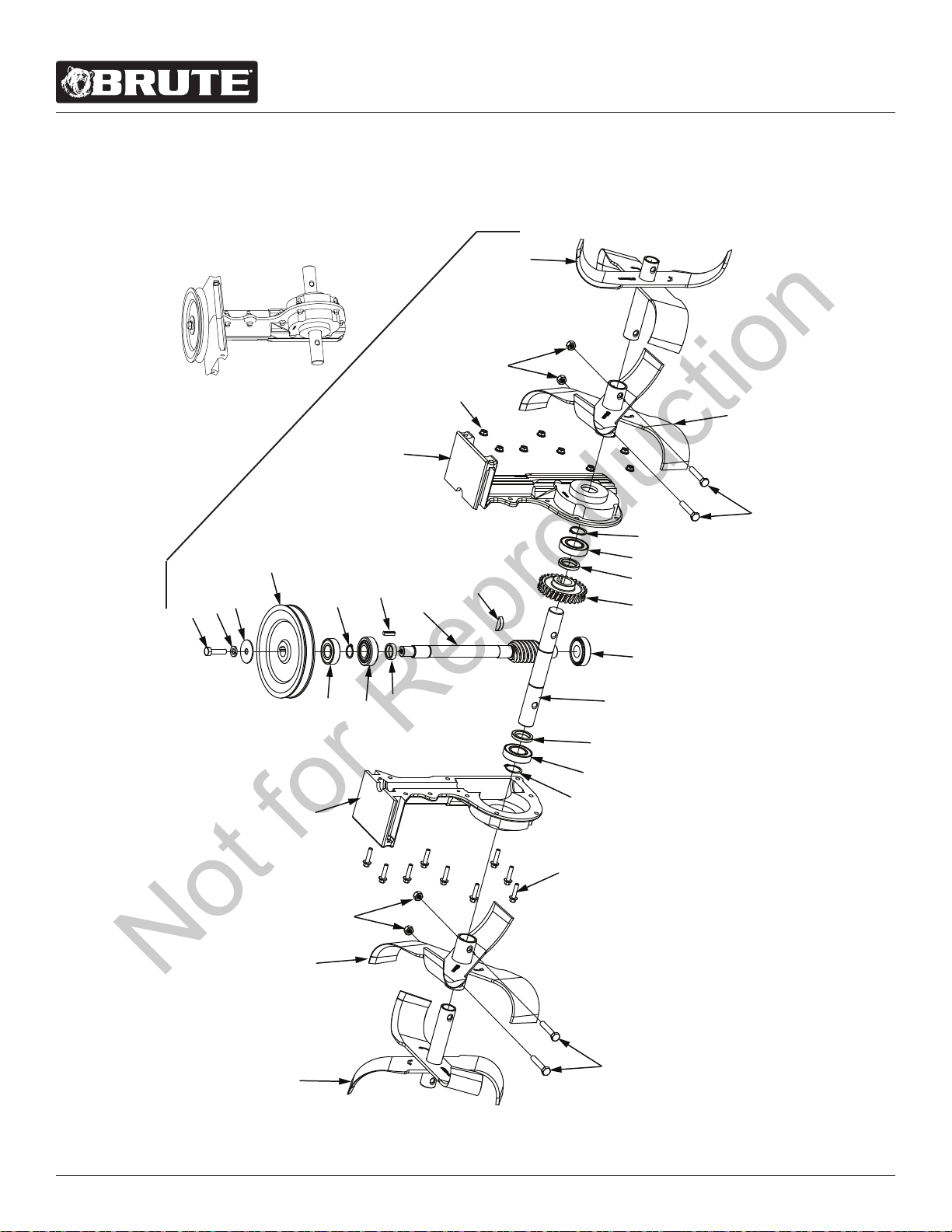
ILLUSTRATED PARTS BREAKDOWN: TINES AND TRANSMISSION ASSEMBLY
1
2
27
4
1
2
4
27
6
7
8
9
10
10
11
11
12
12
13
14
15
16
17
18
19
20
16
22
21
23
24
25
26
Not for Reproduction

For additional information visit online at www.brutepower.com or call 800-743-4115 M-F 8-5 CST
Operator’s Manual
Front Tine Tiller
23
ITEM
NO.
PART # DESCRIPTION QTY.
1 400023 NUT M8 NYLOCK 4
2 3316 BOLT M8 X 1.25 X 45 HEX HEAD 4
3 13905 TINE OUTER RIGHT 1
4 13903 TINE INSIDE 2
5 13904 TINE OUTSIDE LEFT 1
6 13599 NUT M6 X 1.0 NYLOCK 9
7 13600 BOLT M6 X 1.0 X 25 HEX HEAD 9
8 -- ORDER PART NUMBER 13586 TRANSMISSION 1
9 -- ORDER PART NUMBER 13586 TRANSMISSION 1
10 1810 SNAP RING 1 INCH 2
11 13902 BEARING, BALL 25MM ID 6005RS 2
12 14421 SPACER 25MM X 35MM X 5.43MM THICK 2
13 13615 GEAR, BRONZE 25MM ID 6MM KEY 30 TEETH FT 1
14 17990 KEY 6X10 X25MM HALFMOON 1
15 13612 TINE SHAFT 25MM OD 6MM KEY 1
16 3220 BEARING 20X47X15.2 TAPERED ROLLING 30204 2
17 17991 BOLT M8 X 1.25 X 30 HEX HEAD 1
18 1916965 WASHER SPRING LOCK 3/8” 1
19 803 WASHER 5/16 ID X 1-1/2” OD FLAT 16 GA 1
20 13619 PULLEY, TRANSMISSION, SINGLE GROOVE 1
21 3309 BEARING 20MM ID X 42MM OD 6004 2RS 1
22 8924 RETAINING RING 3/4” EXTERNAL 1
23 13590 SPACER, ROUND STEEL 26 X 20.22 X 6.8MM 1
24 17989 KEY 5MM X 5MM X 20MM 1
25 13610 DRIVESHAFT WORM 20MM OD 1
26 13586 TRANSMISSION 7.5:1 WORM BRASS 25MM SHAFT 1
27 21825 BOX, OUTER TINES, WHEEL SHAFT, DRAG STAKE 1
ILLUSTRATED PARTS BREAKDOWN: TINES AND TRANSMISSION ASSEMBLY
Not for Reproduction
For additional information visit online at www.brutepower.com or call 800-743-4115 M-F 8-5 CST
Operator’s Manual
Front Tine Tiller
24
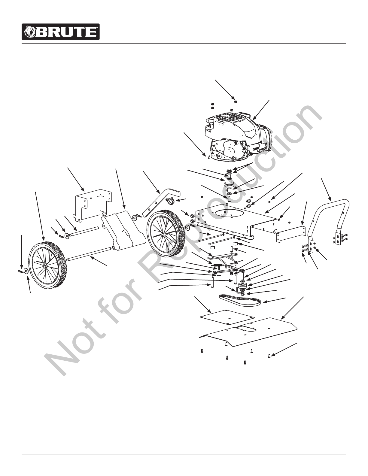
ILLUSTRATED PARTS BREAKDOWN: ENGINE AND CHASSIS PARTS
2
1
44
4
5
3
6
7
43
41
40
42
39
37
36
35
38
34
14
33
32
31
30
28
29
28
45
27
20
24
21
11
18
13
19
14
15
9
16
17
12
10
8
9
8
36
35
46
9
25
22
26
2
23
Not for Reproduction

For additional information visit online at www.brutepower.com or call 800-743-4115 M-F 8-5 CST
Operator’s Manual
Front Tine Tiller
25
ILLUSTRATED PARTS BREAKDOWN: ENGINE AND CHASSIS PARTS
ITEM
NO.
PART # DESCRIPTION QTY.
1* ------ ENGINE 725EXI BRIGGS &
STRATTON
1
2 400023 NUT M8 NYLOCK 5
3 741 ENGINE SPACER 0.9 IN 1
4 3364 KEY, SQUARE 3/16” X 5/8” 1
5 3178 PULLEY SINGLE GROOVE ENGINE
4L
1
6 3245 WASHER M8 X 24 X 2.2 MM 1
7 23172 BOLT 5/16-24 X 1/4 SOCKET
HEAD
1
8 20820 BOLT M10 X 1.5 X 16 HEX HEAD 4
9 4650 NUT M6 X 1.0 NYLOCK 12
10 20824 BOLT M6 X 1.0 X 190 HEX HEAD 2
11 18130 WASHER M6 X 1.5 SPRINGLOCK 2
12 3130ABLK FRAME ENGINE MOUNT 1
13 18134 BOLT M8 X 1.25 X 30 HEX HEAD 1
14 17986 BOLT M6 X 1.0 X 16 HEX HEAD 10
15 20148 WASHER M6 X 18 X 1.6 FLAT 4
16 3335BLK ARM LOWER HANDLEBAR 1
17 23174 COVER 4 HOLE 1
18 744 SPACER FORWARD ARM 10.5 X
22 X 14.5 MM
2
19 20834 BELT GUIDE AND MOUNT 1
20 20144 BOLT M8 X 1.25 X 60 HEX HEAD 1
21 1407 SPRING, FORWARD ARM 1
22 53398 PIN, COTTER 2MM X 16 MM 1
23 1416 PIN CLEVIS 6.3 X 16.8 MM 1
24 53596B YOKE ZINC PLATED CLEVIS 1
25 2431 WASHER M10 X 20 X 2 1
26 400024 WASHER M8 8.4 X 16 X 1.6 1
27 20835 FORWARD ARM 1
ITEM
NO.
PART # DESCRIPTION QTY.
28
W1200126
WASHER M10 X 28 X 2.8 2
29 1413 PULLEY, REVERSE IDLER 1
30 22563 WIREFORM BELT CATCH 1
31
W1265V0903
NUT M10 X 1.5 NYLOCK 1
32 22633 BELT V 4L 12 X 675 TOOTH 1
33 3275BLK SHIELD FRONT TINE FRAME 1
34 23151 TINE SHIELD YELLOW 1
35 20173 COTTER PIN 2.5 X 35 MM 4
36 50175 WASHER 12MM TILLER 4
37 3332 SHAFT TAIL PIVOT 1
38 3331 SHAFT, WHEEL 1
39 1714252 WHEEL & TIRE ASSY 11.0 X 1.75 2
40 18039 PIN LOCK 8MM X 40 MM 1
41 3157 DRAG STAKE FRONT TINE 1
42 3330BLK TAIL MOUNT, LOWER 1
43 23152 TAIL MOUNT UPPER 1
44 21246 SPACER 22.5 X 31.9 X 1.5 MM 2
45 64366 BOLT M8 X 1.25 X 50 HEX HEAD 1
46 720063 SPADE TERMINAL FEMALE 1/4 IN 1
*See engine manual for ordering engine service parts
Not for Reproduction

For additional information visit online at www.brutepower.com or call 800-743-4115 M-F 8-5 CST
Operator’s Manual
Front Tine Tiller
26
NOTES
Not for Reproduction

For additional information visit online at www.brutepower.com or call 800-743-4115 M-F 8-5 CST
Operator’s Manual
Front Tine Tiller
27
NOTES
Not for Reproduction

Brute
PO Box 702
Milwaukee, WI 53201-0702
800-743-4115
www.brutepower.com
All weights, specications and features are approximate and are subject to change without notice. Due to continuous product
improvements, product images may not be exact. Items used for props not included. Some assembly may be required.
Not for Reproduction