
UPS Network Management Card
Network-M2
User's Guide
English
06/29/2022
Edelweiss_and_3.x.x


Eaton is a registered trademark of Eaton Corporation or its subsidiaries and affiliates.
Phillips and Pozidriv are a registered trademarks of Phillips Screw Company.
National Electrical Code and NEC are registered trademarks of National Fire Protection Association, Inc.
Microsoft®, Windows®, and Windows Server® are either registered trademarks or trademarks of Microsoft Corporation in the United States and/or other countries.
UNIX® is a registered trademark of The Open Group.
Linux® is the registered trademark of Linus Torvalds in the U.S. and other countries.
VMware is a registered trademark or trademark of VMware, Inc. in the United States and/or other jurisdictions.
Google™ is a trademark of Google Inc.
All other trademarks are properties of their respective companies.
©Copyright 2019 Eaton Corporation. All rights reserved.
No part of this document may be reproduced in any way without the express written approval of Eaton Corporation.

1 Table of Contents
1 TABLE OF CONTENTS....................................................................................................................................... 4
2 INSTALLING THE NETWORK MANAGEMENT MODULE ............................................................................... 10
2.1 Unpacking the Network module.......................................................................................................................................... 10
2.2 Mounting the Network Module........................................................................................................................................... 10
2.3 Wiring the RS-485 Modbus RTU terminal ........................................................................................................................... 11
2.3.1 Modbus Common/GND (0V pin on terminal block) connection..................................................................................... 11
2.3.2 Cable shield connection (foiled or braided).................................................................................................................... 11
2.3.3 Two-wire networks........................................................................................................................................................ 12
2.3.4 Four-wire networks ....................................................................................................................................................... 12
2.3.5 Configuring the termination........................................................................................................................................... 13
2.4 Accessing the Network Module.......................................................................................................................................... 14
2.4.1 Accessing the web interface through Network............................................................................................................. 14
2.4.2 Finding and setting the IP address ................................................................................................................................ 15
2.4.3 Accessing the web interface through RNDIS................................................................................................................ 16
2.4.4 Accessing the card through serial terminal emulation................................................................................................... 19
2.4.5 Modifying the Proxy exception list ................................................................................................................................ 22
2.5 Configuring Modbus............................................................................................................................................................ 24
2.5.1 Configuring the communication parameters ................................................................................................................. 24
2.5.2 Available maps............................................................................................................................................................... 24
2.5.3 Adding a Custom MAP.................................................................................................................................................. 25
2.5.4 Modbus communication monitoring tool....................................................................................................................... 25
2.5.5 Example of supported Modbus mapping ...................................................................................................................... 25
2.6 Configuring the Network Module settings .......................................................................................................................... 29
2.6.1 Menu structure.............................................................................................................................................................. 29
3 CONTEXTUAL HELP OF THE WEB INTERFACE ............................................................................................. 31
3.1 Login page........................................................................................................................................................................... 31
3.1.1 Logging in for the first time........................................................................................................................................... 31
3.1.2 Specifics ........................................................................................................................................................................ 31
3.1.3 Troubleshooting............................................................................................................................................................. 31
3.2 Home................................................................................................................................................................................... 32
3.2.1 Header structure............................................................................................................................................................ 32
3.2.2 Menu structure.............................................................................................................................................................. 33
3.2.3 Energy flow diagram...................................................................................................................................................... 34
3.2.4 Outlet status.................................................................................................................................................................. 38
3.2.5 Active Alarms ................................................................................................................................................................ 38
3.2.6 Environment .................................................................................................................................................................. 38
3.2.7 Specifics ........................................................................................................................................................................ 39
3.2.8 Energy flow diagram examples ..................................................................................................................................... 39
3.2.9 Access rights per profiles.............................................................................................................................................. 46
3.3 Meters................................................................................................................................................................................. 47
3.3.1 Measures....................................................................................................................................................................... 47
3.3.2 Battery........................................................................................................................................................................... 47
3.3.3 Data logs........................................................................................................................................................................ 48
3.3.4 Default settings and possible parameters - Meters ...................................................................................................... 49
3.3.5 Access rights per profiles.............................................................................................................................................. 49
3.3.6 Save and Restore .......................................................................................................................................................... 49
3.4 Controls ............................................................................................................................................................................... 49

3.4.1 Entire UPS ..................................................................................................................................................................... 49
3.4.2 Outlets - Group 1/ Group 2 ............................................................................................................................................ 50
3.4.3 Specifics ........................................................................................................................................................................ 51
3.4.4 Group............................................................................................................................................................................. 51
3.4.5 Scheduled shutdown..................................................................................................................................................... 53
3.5 Protection ............................................................................................................................................................................ 55
3.5.1 Agents list...................................................................................................................................................................... 55
3.5.2 Agent shutdown sequencing......................................................................................................................................... 58
3.5.3 Shutdown on power outage.......................................................................................................................................... 61
3.6 Environment ........................................................................................................................................................................ 67
3.6.1 Commissioning/Status................................................................................................................................................... 67
3.6.2 Alarm configuration ....................................................................................................................................................... 70
3.6.3 Information .................................................................................................................................................................... 72
3.7 Settings ............................................................................................................................................................................... 73
3.7.1 General .......................................................................................................................................................................... 73
3.7.2 Local users .................................................................................................................................................................... 80
3.7.3 Remote users................................................................................................................................................................ 84
3.7.4 Network & Protocol....................................................................................................................................................... 94
3.7.5 SNMP .......................................................................................................................................................................... 103
3.7.6 Industrial protocols ...................................................................................................................................................... 109
3.7.7 Certificate .................................................................................................................................................................... 116
3.8 Device details .................................................................................................................................................................... 123
3.8.1 General ........................................................................................................................................................................ 123
3.8.2 Settings - UPS ............................................................................................................................................................. 123
3.8.3 Settings - ATS.............................................................................................................................................................. 124
3.9 Maintenance...................................................................................................................................................................... 125
3.9.1 Firmware ..................................................................................................................................................................... 125
3.9.2 Services....................................................................................................................................................................... 128
3.9.3 Resources.................................................................................................................................................................... 132
3.9.4 System logs................................................................................................................................................................. 133
3.9.5 System information ..................................................................................................................................................... 134
3.10 Alarms ............................................................................................................................................................................... 135
3.10.1 Alarm sorting ............................................................................................................................................................... 135
3.10.2 Active alarm counter.................................................................................................................................................... 135
3.10.3 Alarm details................................................................................................................................................................ 135
3.10.4 Alarm paging................................................................................................................................................................ 135
3.10.5 Export .......................................................................................................................................................................... 135
3.10.6 Clear ............................................................................................................................................................................ 135
3.10.7 Specifics ...................................................................................................................................................................... 135
3.10.8 Alarms list with codes ................................................................................................................................................. 135
3.10.9 Access rights per profiles............................................................................................................................................ 136
3.11 User profile........................................................................................................................................................................ 136
3.11.1 Access to the user profile............................................................................................................................................ 136
3.11.2 User profile.................................................................................................................................................................. 136
3.11.3 Legal information......................................................................................................................................................... 137
3.11.4 Component.................................................................................................................................................................. 137
3.11.5 Availability of source code........................................................................................................................................... 137
3.11.6 Notice for proprietary elements................................................................................................................................... 137
3.11.7 Specifics ...................................................................................................................................................................... 137
3.11.8 Default settings and possible parameters - User profile ............................................................................................. 137
3.11.9 Access rights per profiles............................................................................................................................................ 137
3.11.10 CLI commands ............................................................................................................................................................ 138
3.11.11 Troubleshooting........................................................................................................................................................... 138
3.11.12 Save and Restore ........................................................................................................................................................ 139

3.12 Documentation.................................................................................................................................................................. 140
3.12.1 Access to the embedded documentation ................................................................................................................... 140
3.12.2 Specifics ...................................................................................................................................................................... 141
3.12.3 Access rights per profiles............................................................................................................................................ 141
4 SERVICING THE NETWORK MANAGEMENT MODULE ............................................................................... 142
4.1 Configuring/Commissioning/Testing LDAP ....................................................................................................................... 142
4.1.1 Commissioning............................................................................................................................................................ 142
4.1.2 Testing LDAP authentication....................................................................................................................................... 143
4.1.3 Limitations................................................................................................................................................................... 143
4.2 Pairing agent to the Network Module ............................................................................................................................... 143
4.2.1 Pairing with credentials on the agent .......................................................................................................................... 143
4.2.2 Pairing with automatic acceptance (recommended if done in a secure and trusted network).................................... 144
4.2.3 Pairing with manual acceptance.................................................................................................................................. 144
4.3 Powering down/up applications (examples) ...................................................................................................................... 145
4.3.1 Powering down IT system in a specific order ............................................................................................................. 145
4.3.2 Powering down non-priority equipment first............................................................................................................... 148
4.3.3 Restart sequentially the IT equipment on utility recovery ........................................................................................... 151
4.4 Checking the current firmware version of the Network Module....................................................................................... 152
4.5 Accessing to the latest Network Module firmware/driver/script....................................................................................... 152
4.6 Upgrading the card firmware (Web interface / shell script) ............................................................................................... 153
4.6.1 Web interface.............................................................................................................................................................. 153
4.6.2 Shell script................................................................................................................................................................... 153
4.6.3 Example:...................................................................................................................................................................... 153
4.7 Changing the RTC battery cell........................................................................................................................................... 154
4.8 Updating the time of the Network Module precisely and permanently (ntp server) ......................................................... 157
4.9 Synchronizing the time of the Network Module and the UPS........................................................................................... 157
4.9.1 Automatic time synchronization .................................................................................................................................. 157
4.9.2 Manual time synchronization....................................................................................................................................... 157
4.10 Changing the language of the web pages......................................................................................................................... 157
4.11 Resetting username and password................................................................................................................................... 158
4.11.1 As an admin for other users ........................................................................................................................................ 158
4.11.2 Resetting its own password........................................................................................................................................ 158
4.12 Recovering main administrator password ......................................................................................................................... 158
4.13 Switching to static IP (Manual) / Changing IP address of the Network Module................................................................ 160
4.14 Reading device information in a simple way ..................................................................................................................... 160
4.14.1 Web page .................................................................................................................................................................... 160
4.15 Subscribing to a set of alarms for email notification.......................................................................................................... 160
4.15.1 Example #1: subscribing only to one alarm (load unprotected)................................................................................... 160
4.15.2 Example #2: subscribing to all Critical alarms and some specific Warnings ............................................................... 161
4.16 Saving/Restoring/Duplicating Network module configuration settings ............................................................................. 163
4.16.1 Modifying the JSON configuration settings file........................................................................................................... 163
4.16.2 Saving/Restoring/Duplicating settings through the CLI............................................................................................... 167
4.16.3 Saving/Restoring/Duplicating settings through the Web interface.............................................................................. 167
5 SECURING THE NETWORK MANAGEMENT MODULE................................................................................ 168
5.1 Cybersecurity considerations for electrical distribution systems ...................................................................................... 168
5.1.1 Purpose ....................................................................................................................................................................... 168
5.1.2 Introduction ................................................................................................................................................................. 168
5.1.3 Connectivity—why do we need to address cybersecurity for industrial control systems (ICS)? ................................ 168
5.1.4 Cybersecurity threat vectors ....................................................................................................................................... 168
5.1.5 Defense in depth......................................................................................................................................................... 169
5.1.6 Designing for the threat vectors.................................................................................................................................. 170
5.1.7 Policies, procedures, standards, and guidelines.......................................................................................................... 172

5.1.8 Conclusion................................................................................................................................................................... 174
5.1.9 Terms and definitions.................................................................................................................................................. 174
5.1.10 Acronyms .................................................................................................................................................................... 174
5.1.11 References .................................................................................................................................................................. 175
5.2 Cybersecurity recommended secure hardening guidelines .............................................................................................. 176
5.2.1 Introduction ................................................................................................................................................................. 176
5.2.2 Secure configuration guidelines .................................................................................................................................. 176
5.2.3 References .................................................................................................................................................................. 182
5.3 Configuring user permissions through profiles.................................................................................................................. 183
5.4 Decommissioning the Network Management module ..................................................................................................... 183
6 SERVICING THE EMP .................................................................................................................................... 185
6.1 Description and features ................................................................................................................................................... 185
6.2 Unpacking the EMP........................................................................................................................................................... 185
6.3 Installing the EMP ............................................................................................................................................................. 186
6.3.1 Defining EMPs address and termination..................................................................................................................... 186
6.3.2 Mounting the EMP ...................................................................................................................................................... 186
6.3.3 Cabling the first EMP to the device............................................................................................................................. 189
6.3.4 Daisy chaining EMPs................................................................................................................................................... 190
6.3.5 Connecting an external contact device........................................................................................................................ 191
6.4 Commissioning the EMP................................................................................................................................................... 191
6.4.1 On the Network Module device .................................................................................................................................. 191
6.5 Using the EMP for temperature compensated battery charging....................................................................................... 191
6.5.1 Addressing the EMP.................................................................................................................................................... 192
6.5.2 Commissioning the EMP............................................................................................................................................. 192
6.5.3 Enabling temperature compensated battery charging in the UPS............................................................................... 192
7 INFORMATION............................................................................................................................................... 193
7.1 Front panel connectors and LED indicators....................................................................................................................... 193
7.2 Specifications/Technical characteristics ............................................................................................................................ 196
7.3 Default settings and possible parameters......................................................................................................................... 197
7.3.1 Meters......................................................................................................................................................................... 197
7.3.2 Settings ....................................................................................................................................................................... 197
7.3.3 Sensors alarm configuration........................................................................................................................................ 204
7.3.4 User profile.................................................................................................................................................................. 204
7.4 Access rights per profiles.................................................................................................................................................. 206
7.4.1 Home........................................................................................................................................................................... 206
7.4.2 Meters......................................................................................................................................................................... 206
7.4.3 Controls ....................................................................................................................................................................... 206
7.4.4 Protection .................................................................................................................................................................... 206
7.4.5 Environment ................................................................................................................................................................ 206
7.4.6 Settings ....................................................................................................................................................................... 207
7.4.7 Maintenance................................................................................................................................................................ 208
7.4.8 Alarms ......................................................................................................................................................................... 208
7.4.9 User profile.................................................................................................................................................................. 208
7.4.10 Contextual help............................................................................................................................................................ 208
7.4.11 CLI commands ............................................................................................................................................................ 209
7.5 List of event codes............................................................................................................................................................ 210
7.5.1 System log codes........................................................................................................................................................ 210
7.5.2 UPS(HID) alarm log codes ........................................................................................................................................... 214
7.5.3 UPS(XCP and COPI) alarm log codes .......................................................................................................................... 218
7.5.4 ATS alarm log codes.................................................................................................................................................... 224
7.5.5 EMP alarm log codes................................................................................................................................................... 226
7.5.6 Network module alarm log codes................................................................................................................................ 227

7.6 SNMP traps ....................................................................................................................................................................... 228
7.6.1 UPS Mib ...................................................................................................................................................................... 228
7.6.2 ATS Mib....................................................................................................................................................................... 229
7.6.3 Sensor Mib .................................................................................................................................................................. 230
7.7 CLI ..................................................................................................................................................................................... 231
7.7.1 Commands available.................................................................................................................................................... 231
7.7.2 Contextual help............................................................................................................................................................ 231
7.7.3 get release info............................................................................................................................................................ 232
7.7.4 history.......................................................................................................................................................................... 232
7.7.5 logout........................................................................................................................................................................... 233
7.7.6 maintenance................................................................................................................................................................ 233
7.7.7 modbus_message_display .......................................................................................................................................... 233
7.7.8 modbus_statistics........................................................................................................................................................ 234
7.7.9 netconf ........................................................................................................................................................................ 235
7.7.10 ping and ping6 ............................................................................................................................................................. 237
7.7.11 reboot .......................................................................................................................................................................... 237
7.7.12 save_configuration | restore_configuration.................................................................................................................. 238
7.7.13 sanitize......................................................................................................................................................................... 239
7.7.14 ssh-keygen .................................................................................................................................................................. 239
7.7.15 time ............................................................................................................................................................................. 240
7.7.16 traceroute and traceroute6.......................................................................................................................................... 241
7.7.17 whoami........................................................................................................................................................................ 241
7.7.18 email-test..................................................................................................................................................................... 242
7.7.19 systeminfo_statistics................................................................................................................................................... 242
7.7.20 certificates................................................................................................................................................................... 243
7.8 Legal information............................................................................................................................................................... 244
7.8.1 Availability of Source Code.......................................................................................................................................... 244
7.8.2 Notice for Open Source Elements............................................................................................................................... 244
7.8.3 Notice for our proprietary (i.e. non-Open source) elements........................................................................................ 245
7.9 Acronyms and abbreviations ............................................................................................................................................. 246
8 TROUBLESHOOTING..................................................................................................................................... 249
8.1 Action not allowed in Control/Schedule/Power outage policy........................................................................................... 249
8.1.1 Symptom..................................................................................................................................................................... 249
8.1.2 Possible Cause ............................................................................................................................................................ 249
8.1.3 Action .......................................................................................................................................................................... 249
8.2 Card wrong timestamp leads to "Full acquisition has failed" error message on Software................................................. 249
8.2.1 Symptoms: .................................................................................................................................................................. 249
8.2.2 Possible cause:............................................................................................................................................................ 249
8.2.3 Action: ......................................................................................................................................................................... 249
8.3 Client server is not restarting ............................................................................................................................................ 249
8.3.1 Symptom..................................................................................................................................................................... 249
8.3.2 Possible Cause ............................................................................................................................................................ 249
8.3.3 Action .......................................................................................................................................................................... 250
8.4 EMP detection fails at discovery stage ............................................................................................................................. 250
8.4.1 Symptom #1................................................................................................................................................................ 250
8.4.2 Symptom #2................................................................................................................................................................ 250
8.5 How do I log in if I forgot my password? .......................................................................................................................... 251
8.5.1 Action .......................................................................................................................................................................... 251
8.6 Software is not able to communicate with the Network module...................................................................................... 251
8.6.1 Symptoms ................................................................................................................................................................... 251
8.6.2 Possible cause............................................................................................................................................................. 251
8.6.3 Setup ........................................................................................................................................................................... 251
8.6.4 Action #1 ..................................................................................................................................................................... 251

8.6.5 Action #2 ..................................................................................................................................................................... 252
8.7 LDAP configuration/commissioning is not working........................................................................................................... 252
8.8 Modbus communication doesn't work.............................................................................................................................. 252
8.8.1 Symptoms ................................................................................................................................................................... 252
8.8.2 Possible cause............................................................................................................................................................. 252
8.9 Password change in My profile is not working.................................................................................................................. 254
8.9.1 Symptoms ................................................................................................................................................................... 254
8.9.2 Possible cause............................................................................................................................................................. 254
8.9.3 Action .......................................................................................................................................................................... 254
8.10 SMTP server configuration does not work with Gmail...................................................................................................... 254
8.10.1 Symptom..................................................................................................................................................................... 254
8.10.2 Cause........................................................................................................................................................................... 254
8.10.3 Action .......................................................................................................................................................................... 254
8.11 SNMPv3 password management issue with Save and Restore ....................................................................................... 254
8.11.1 Affected FW versions.................................................................................................................................................. 254
8.11.2 Symptom..................................................................................................................................................................... 254
8.11.3 Cause........................................................................................................................................................................... 254
8.11.4 Action .......................................................................................................................................................................... 255
8.12 The alarm list has been cleared after an upgrade.............................................................................................................. 255
8.12.1 Symptom..................................................................................................................................................................... 255
8.12.2 Action .......................................................................................................................................................................... 255
8.13 The Network Module fails to boot after upgrading the firmware ...................................................................................... 255
8.13.1 Possible Cause ............................................................................................................................................................ 255
8.13.2 Action .......................................................................................................................................................................... 255
8.14 Web user interface is not up to date after a FW upgrade ................................................................................................. 256
8.14.1 Symptom..................................................................................................................................................................... 256

Unpacking the Network module
Installing the Network Management Module – 10
•
•
•
•
•
•
•
•
•
•
2 Installing the Network Management Module
2.1 Unpacking the Network module
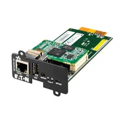
The Network-M2 will include the following accessories:
Installation instructions
USB AM to Micro USB/M/5P 5ft Cable
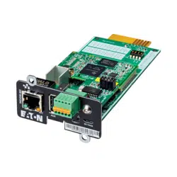
The INDGW-M2
will include the following accessories:
Installation instructions
USB AM to Micro USB/M/5P 5ft Cable
RS-485 wiring terminal
The INDGW-X2
will include the following accessories:
Installation instructions
USB AM to Micro USB/M/5P 5ft Cable
RS-485 wiring terminal
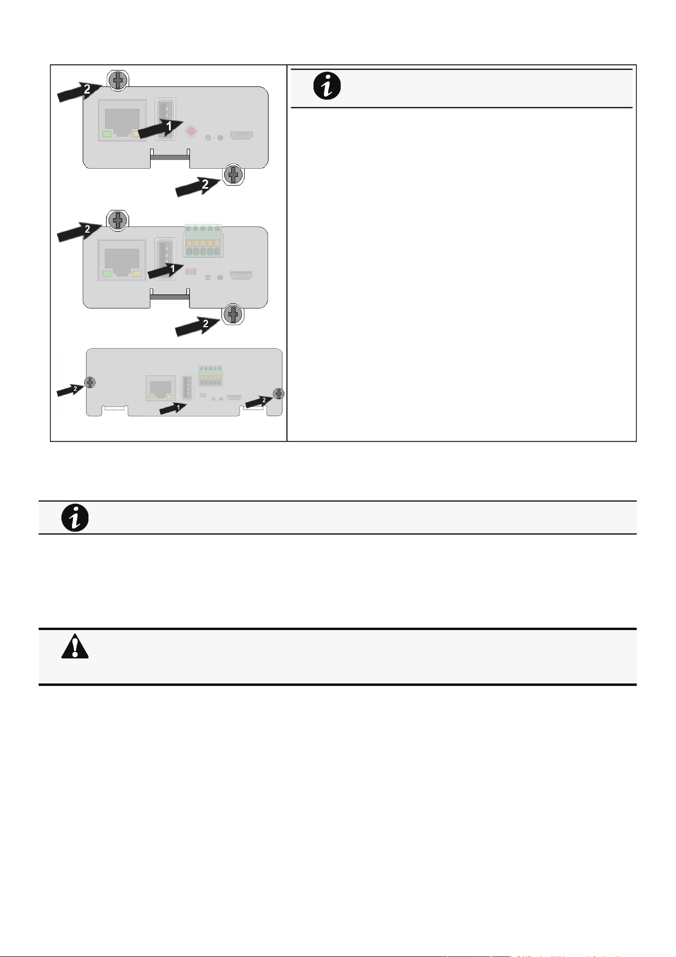
2.2 Mounting the Network Module
The Network Module is hot-swappable. Inserting and/or extracting the Network Module from the communication slot of theproduct
has no effect on the output.
Remove the two screws securing the option slot cover plate and store the plate for possible future use.
Install theNetwork Module along the alignment channels in the option slot.
Secure the Network Module using the two screws.
Packing materials must be disposed of in compliance with all local regulations concerning waste.
Recycling symbols are printed on the packing materials to facilitate sorting.
It is not necessary to power down theDevice before installing the Network Module. Required tools: No. 2 Phillips
screwdriver.
Wiring the RS-485 Modbus RTU terminal
Installing the Network Management Module – 11
2.3 Wiring the RS-485 Modbus RTU terminal
The Modbus Network Module provides an easy path for integrating an
Eaton
UPS into an RS-485 Modbus network and also provides isolation of the communication between the UPS and the RS-485 Modbus
network.
Use the terminal strip on the ModbusNetwork Module to wire into a two-wire network.
2.3.1 Modbus Common/GND (0V pin on terminal block)connection
The Network Module is an isolated device, if all the other devices on the network are isolated, common/GND (0V pin on terminal
block) should be connected between devices to limit common mode voltage.
Common/GND (0V pin on terminal block) should not be connected to any other devices that is not isolatedto avoid ground loops.
2.3.2 Cable shield connection (foiled or braided)
The cable shield should be continuous on the entire length of the bus and should be connected to ground (earth) at only one point
to limit the flow of ground-loop currents in the shield caused by ground potential differences.
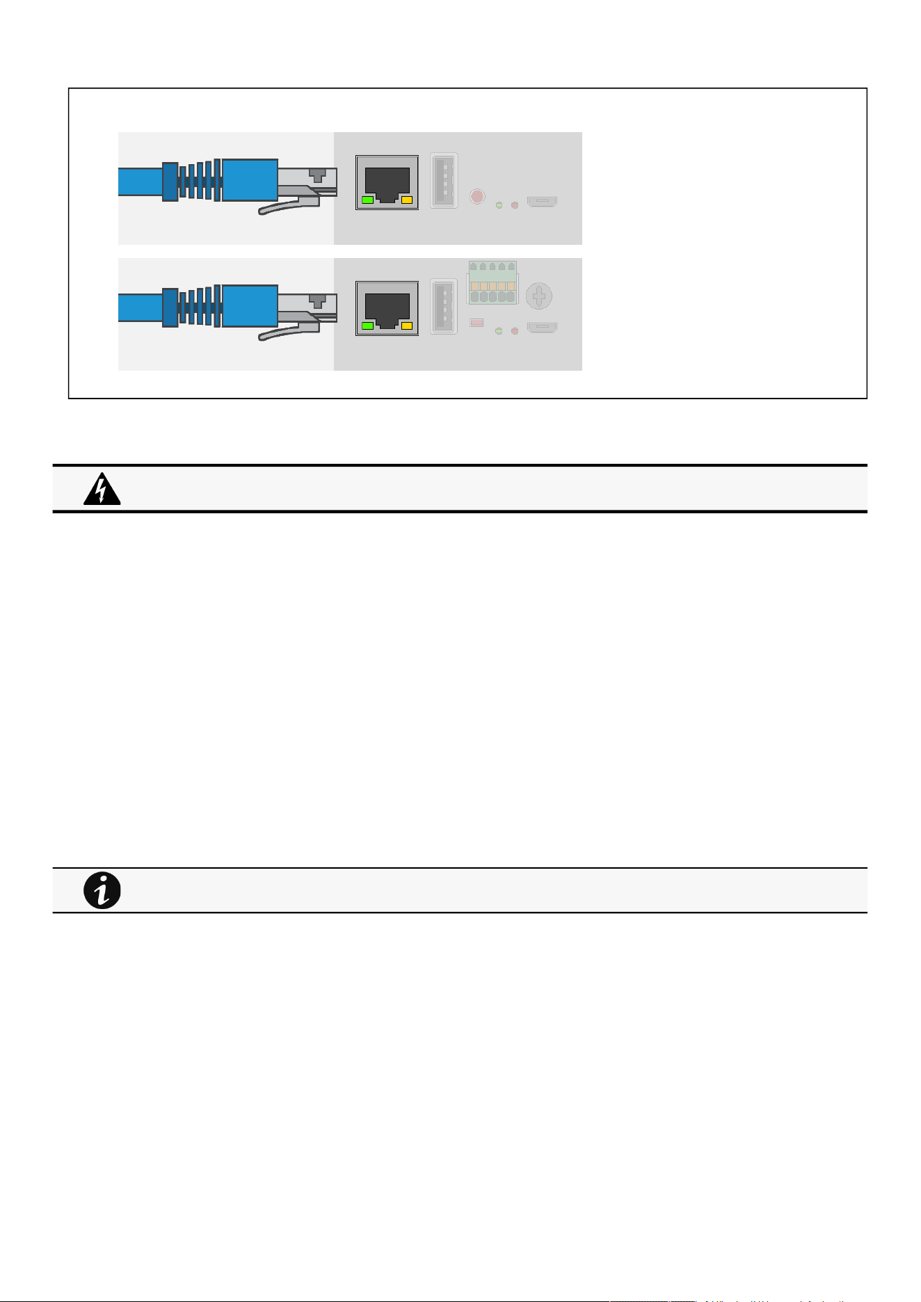
If theproduct is powered up, you can verify that the Network
Module is seated properly and communicating with theproduct by
checking that the Status ON LEDflashes green after 2 minutes.
This section is only for the INDGW
If the Modbus Network Module is the last device installed in the network chain or the length of the network cable is
excessive, termination needs to be enabled.
For details on termination, see theInstalling the Network Management Module>>>Wiring the RS-485 Modbus
RTU terminal>>>Configuring the termination
section.
Wiring the RS-485 Modbus RTU terminal
Installing the Network Management Module – 12
•
•
•
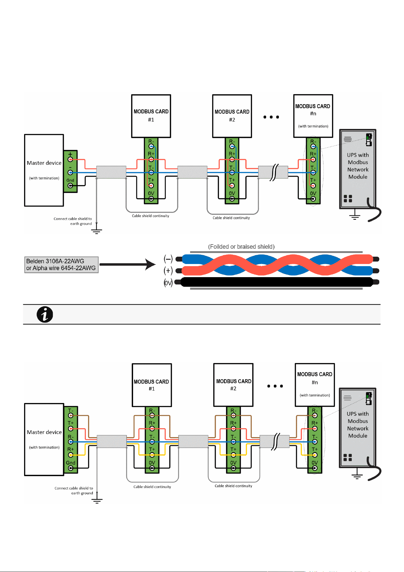
2.3.3 Two-wire networks
Interconnect R- with T- and R+ with T+ onthe Modbus Network Moduleterminal strip.
Connect the RS-485 network signal + to the R+ or T+ on the Modbus Network Moduleterminal strip.
Connect the RS-485 network signal – to the R- or T- on the ModbusNetwork Moduleterminal strip.
2.3.4 Four-wire networks
All four RS-485 network signals including T-, T+, R–, and R+ must be connected respectively to the terminal strip R-, R+, T-, T+.
Belden 3106A-22AWG or equivalent cabling (a 1.5 twisted-pair shielded 120Ω cable with ground) is recommended.
Wiring the RS-485 Modbus RTU terminal
Installing the Network Management Module – 13
1.
2.
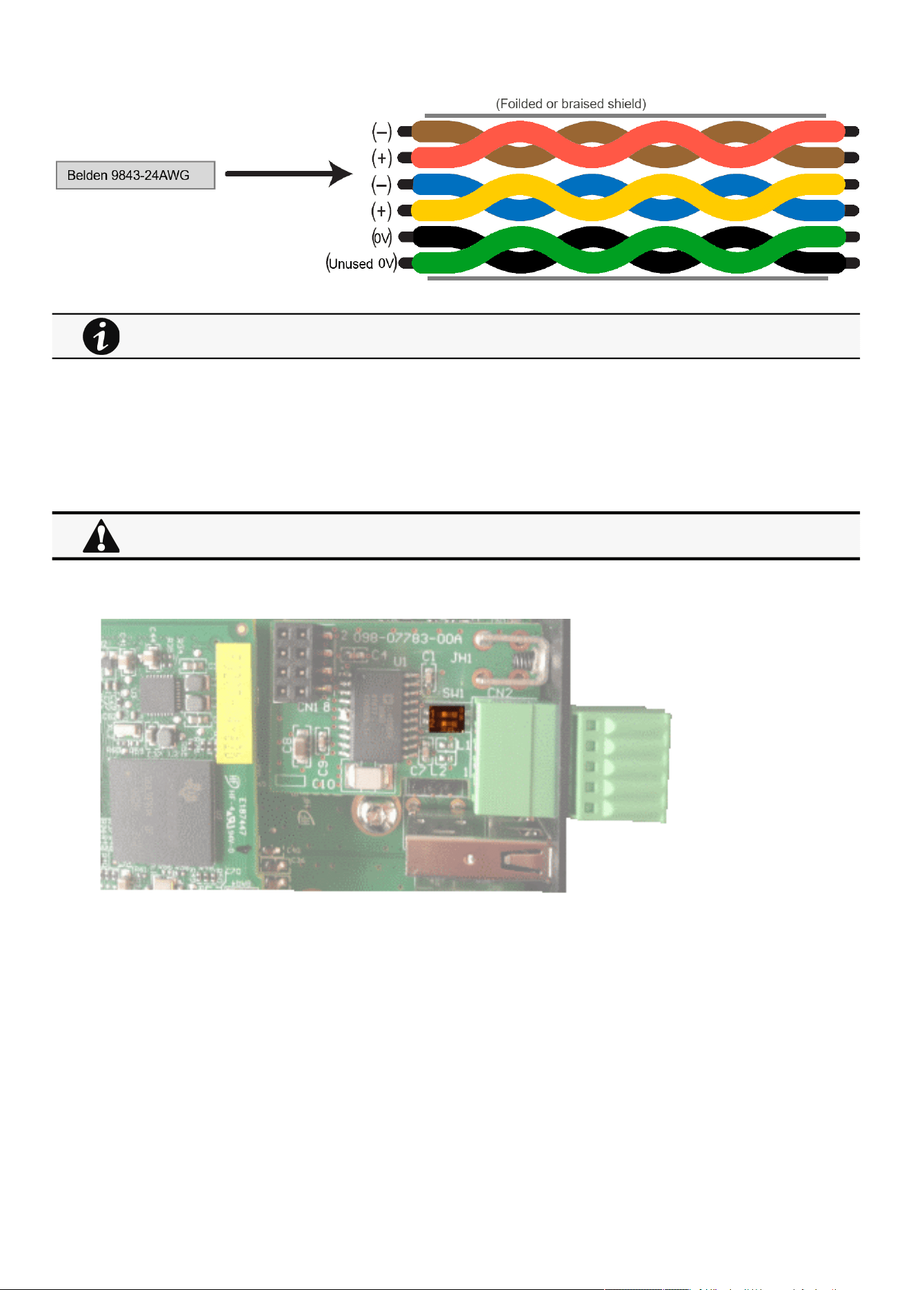
2.3.5 Configuring the termination
If the INDGW card is the last device installed in the network chain or the length of the network cable is excessive, termination
needs to be enabled.
Termination is used to match impedance of a node to the impedance of the transmission line being used. When impedances are
mismatched, the transmitted signal is not completely absorbed by the load and a portion is reflected into the transmission line.
To enable the on-board termination resistor (120Ω):
Locate the termination switch that is located on the top of the Modbus Network Module.
Peel off the protection:
Belden 9843-24AWG or equivalent cabling (3 twisted-pair shielded 120Ω cable with ground) is recommended.
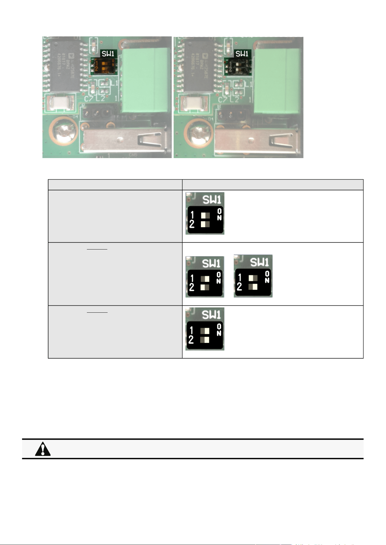
No more than two termination points should be used in the RS-485 network.
Accessing the Network Module
Installing the Network Management Module – 14
3.
Change the position of the termination switch according to your needs:
Switch position
No termination (default)
Termination for two-wire networks One of the two position below can be used:
or
Termination for four-wire networks
2.4 Accessing the Network Module
2.4.1 Accessing the web interface through Network
2.4.1.1 Connecting the network cable
Security settings in the Network Module may be in their default states.
For maximum security, configure through a USB connection before connecting the network cable.
Accessing the Network Module
Installing the Network Management Module – 15
•
•
•
•
Connect a standard
gigabit compatible shielded ethernetcable (F/UTP or F/FTP)
between the network connector on theNetwork Module and a
network jack.
2.4.1.2 Accessing the web interface
STEP 1 –On a network computer, launch a supported web browser. The browser window appears.
STEP 2 –In the Address/Location field, enterhttps://
[IPaddress]
with the static IP address of the Network Module.
STEP 3 –The login screen appears.
STEP 4 –Enter the user name in the User Name field. The default user name is admin.
STEP 5 –Enter the password in the Password field. The default password is admin.
STEP 6 –The password must be changed at first login.
STEP 7 –Click Login. The Network Module web interface appears.
2.4.2 Finding and setting the IP address
2.4.2.1 Your network is equipped with a BOOTP/DHCP server (default)
2.4.2.1.1 Read from the device LCD
If your device has an LCD, from the LCD’s menu, navigate to Identification>>>"COM card IPv4".
Note the IP address of the card.
Go to the section: Accessing the web interface through Network.
2.4.2.1.2 With web browser throughthe configuration port
For example, if your device does not have an LCD, the IP address can be discovered by accessing the web interface through RNDIS
andbrowsing to Settings>Network.
To access the web interface through RNDIS, see theAccessing the web interface through RNDISsection.
Navigate toContextual help>>>Settings>>>Network & Protocol>>>IPV4.
Read the IPv4 settings.
It is highly recommended that browser access to the Network Module is isolated from outside access using a
firewall or isolated network.
Note: some older Devices may not be able to display the IP address even if they have an LCD. Please consult the
Device manual.
Accessing the Network Module
Installing the Network Management Module – 16
•
•
•
•
2.4.2.2 Your network is not equipped with a BOOTP/DHCP server
2.4.2.2.1 Define from the configuration port
The IP address can be defined by accessing the web interface through RNDIS.
To access web interface through RNDIS, see theAccessing the web interface through RNDISsection.
Define the IP settings:
Navigate toContextual help>>>Settings>>>Network & Protocol>>>IPV4.
Select Manual (Static IP).
Input the following information: Address, Subnet Mask, Default Gateway
Save the changes.
2.4.3 Accessing the web interface through RNDIS
This connection is used to access and configure the Network Module network settings locally through a RNDIS(Ethernet over USB
interface).
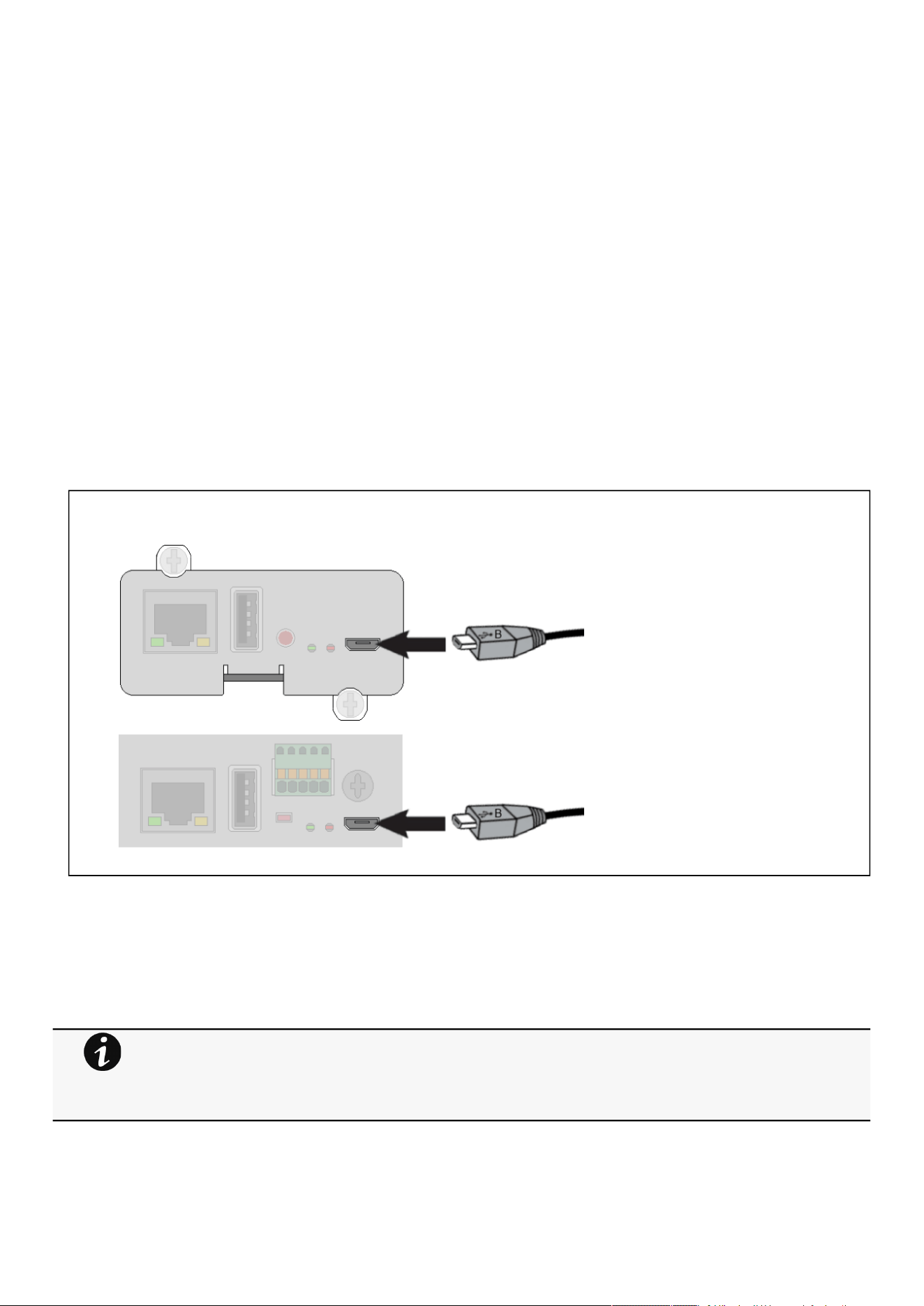
2.4.3.1 Connecting the configuration cable
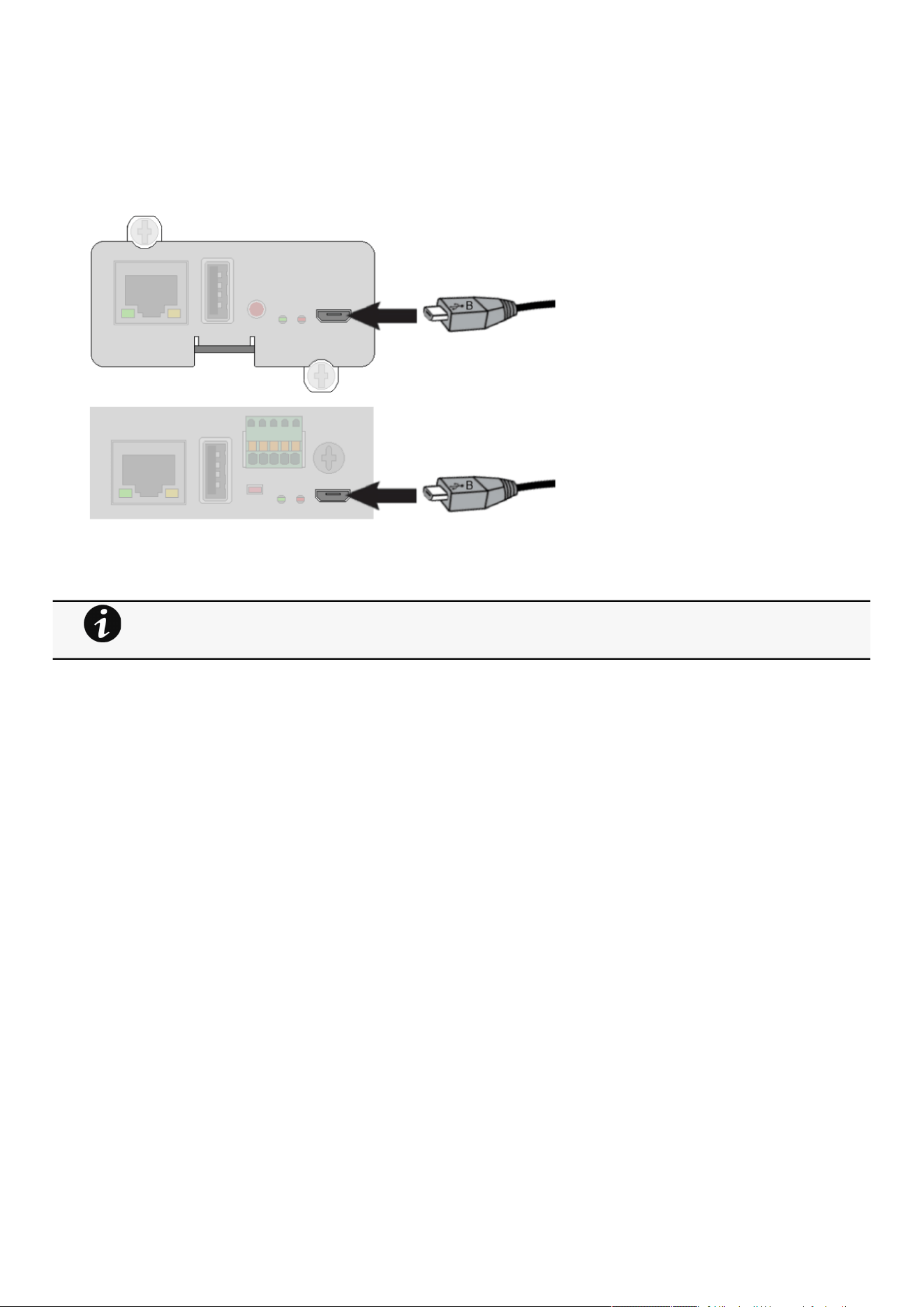
1.Connect the Micro-B to USB cable to a USB connector on the host computer.
2. Connect the cable to the Settings connector on theNetwork Module.
2.4.3.2 Web interface access through RNDIS
2.4.3.2.1 Configuring the RNDIS
a Automatic configuration
RNDIS driver is used to emulate a network connection from USB.
After the card is connected to the PC, Windows® OS will automatically search for the RNDIS driver.
On some computers, the OS can find the RNDIS driver then configuration is completed, and you can go to
Accessing the web interface.
On some others it may fail then proceed to manual configuration.
Accessing the Network Module
Installing the Network Management Module – 17
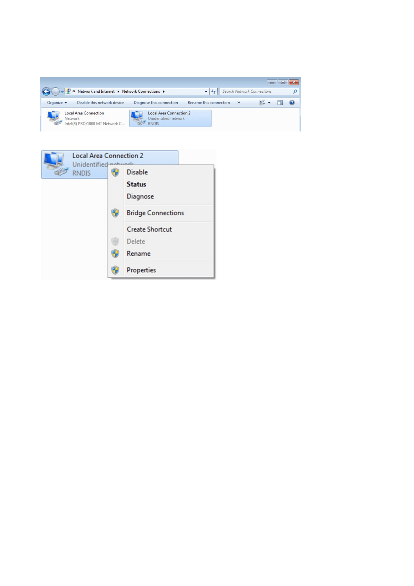
b Manual configuration
STEP 1 –In case Windows® OS fails to find driver automatically, go to theWindows control panel>Network and sharing
center>Local area connection
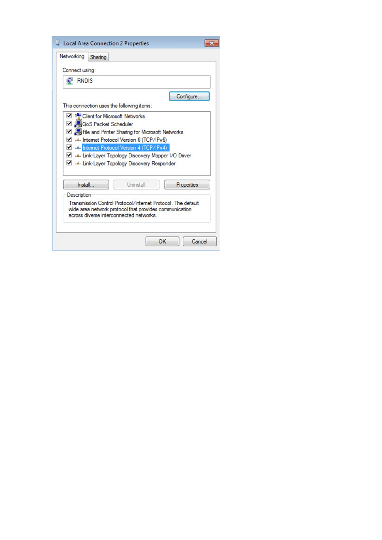
STEP 2 –Right click on the RNDIS local area connection and select Properties.
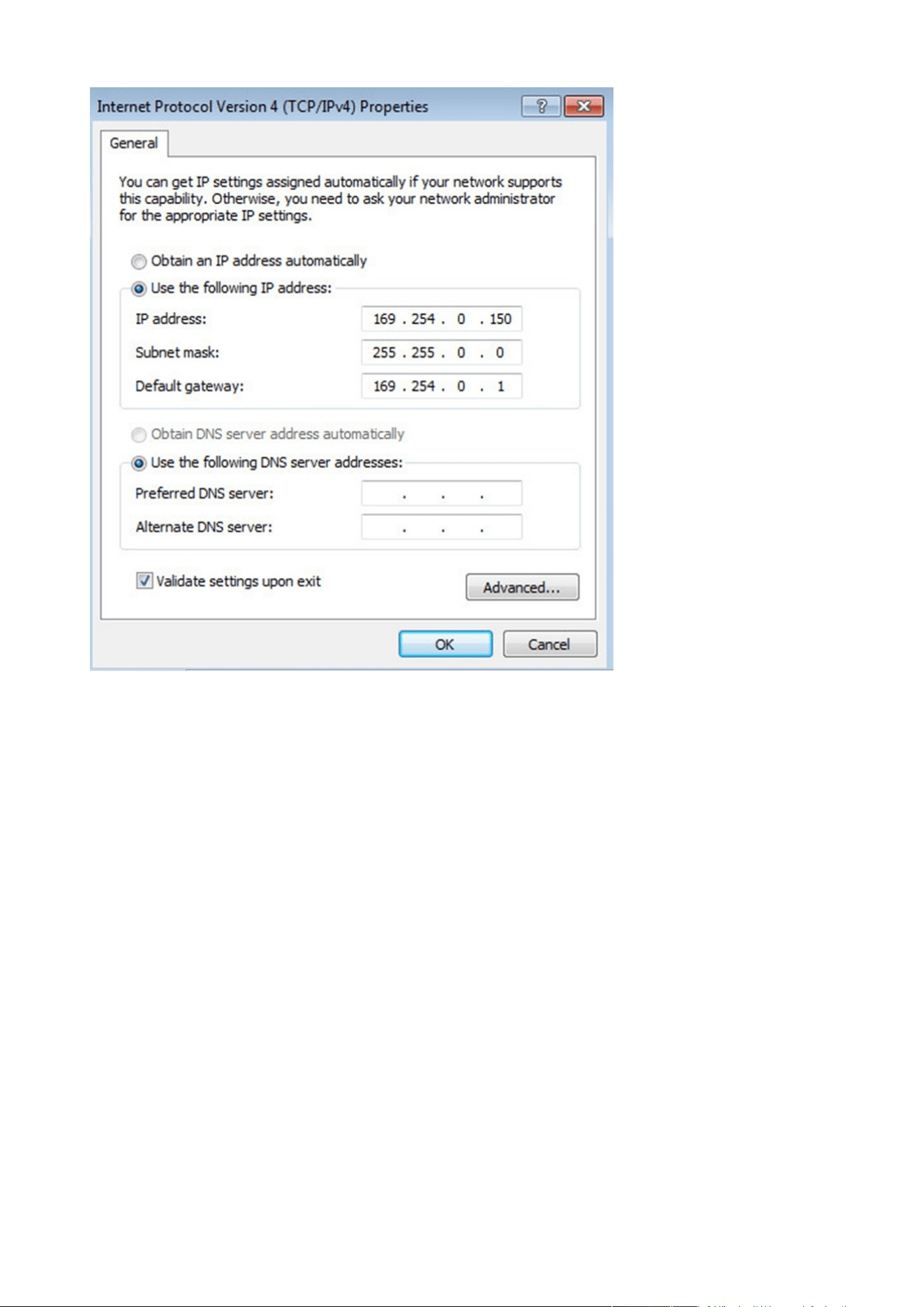
STEP 3 –Select Internet Protocol Version 4 (TCP/IPv4)” and press the Properties button
Accessing the Network Module
Installing the Network Management Module – 18
STEP 4– Then enter the configuration as below and validate (IP = 169.254.0.150 and mask = 255.255.0.0), click OK, then click on
Close.
Accessing the Network Module
Installing the Network Management Module – 19
2.4.3.2.2 Accessing the web interface
STEP 1 –Be sure that the Deviceis powered on.
STEP 2 – On the host computer, download the rndis.7z file from the website www.eaton.com/downloads and extract it. For more
information, navigate toServicing the Network Management Module>>>Accessing to the latest Network Module firmware/
driversection.
STEP 3 – Launch setProxy.bat to add 169.254.* in proxy’s exceptions list, if needed. For manual configuration, navigate to Installing
the Network Management Module>>>Accessing the Network Module>>>Modifying the Proxy exception list section in the full
documentation.
STEP 4 –Launch a supported browser, the browser window appears.
STEP 5 –In the Address/Location field, enter: https://169.254.0.1, the static IP address of the Network Module for RNDIS. The log
in screen appears.
STEP 6 –Enter the user name in the User Name field. The default user name isadmin.
STEP 7 –Enter the password in the Password field. The default password isadmin.
STEP 8 –ClickLogin. The Network Module local web interface appears.
2.4.4 Accessing the card through serial terminal emulation
This connection is used to access and configure the Network Module network settings locally through Serial (Serial over USB
interface).
Accessing the Network Module
Installing the Network Management Module – 20
2.4.4.1 Connecting the configuration cable
STEP 1 – Connect the Micro-B to USB cable to a USB connector on the host computer.
STEP 2 – Connect the cable to the Settings connector on theNetwork Module.
2.4.4.2 Manual configuration of the serial connection
STEP 1 –On the host computer,download therndis.7z file from the website www.eaton.com/downloads and extract it.
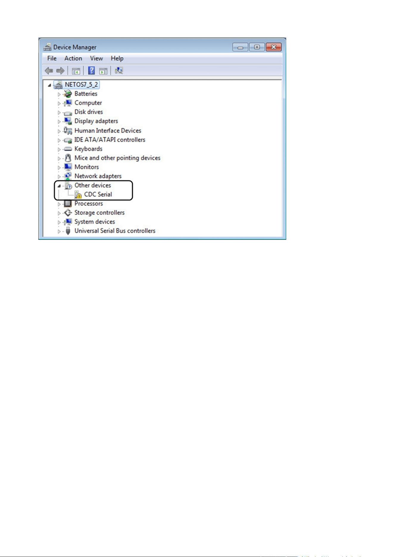
STEP 2 – Plug the USB cable and go toWindows® Device Manager.
STEP 3 – Check the CDC Serial in the list, if it is with a yellow exclamation mark implying that driver has not been installed follow
the steps 4-5-6-7 otherwise configuration is OK.
Serial driver is used to emulate a serial connection from USB.
After the card is connected to the PC, manual configuration of the driver is needed for Windows® OS to discover
the serial connection.
Accessing the Network Module
Installing the Network Management Module – 21
STEP 4 – Right click on it and select Update Driver Software. When prompted to choose how to search for device driver software,
choose Browse my computer for driver software. Select Let me pick from a list of device drivers on my computer.
STEP 5 – Select the folder where you have previously downloaded the driver file Click on Next.
STEP 6 – A warning window will come up because the driver is not signed. Select Install this driver software anyway
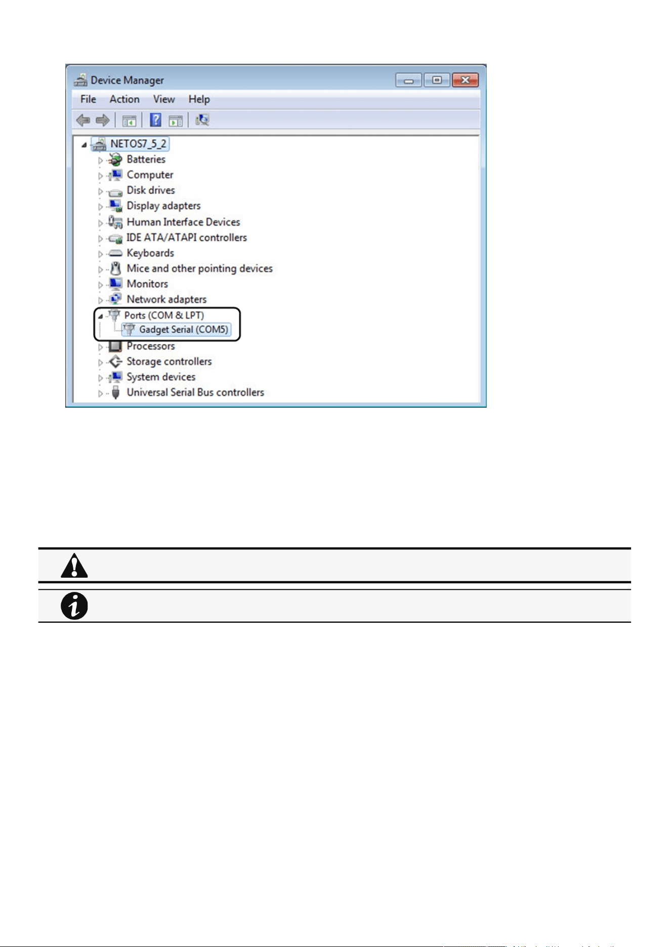
STEP 7 – The installation is successful when the COM port number is displayed for the Gadget Serial device in theWindows®
Device Manager.
Accessing the Network Module
Installing the Network Management Module – 22
•
•
•
•
2.4.4.3 Accessing the card through Serial
It is intended mainly for automated configuration of the network and time settings of the network card. It can also be used for
troubleshooting and remote reboot/reset of the network interface in case the web user interface is not accessible.
CLI can be accessed through:
SSH
Serial terminal emulation.
For more details, refer toInformation>>>CLIsection
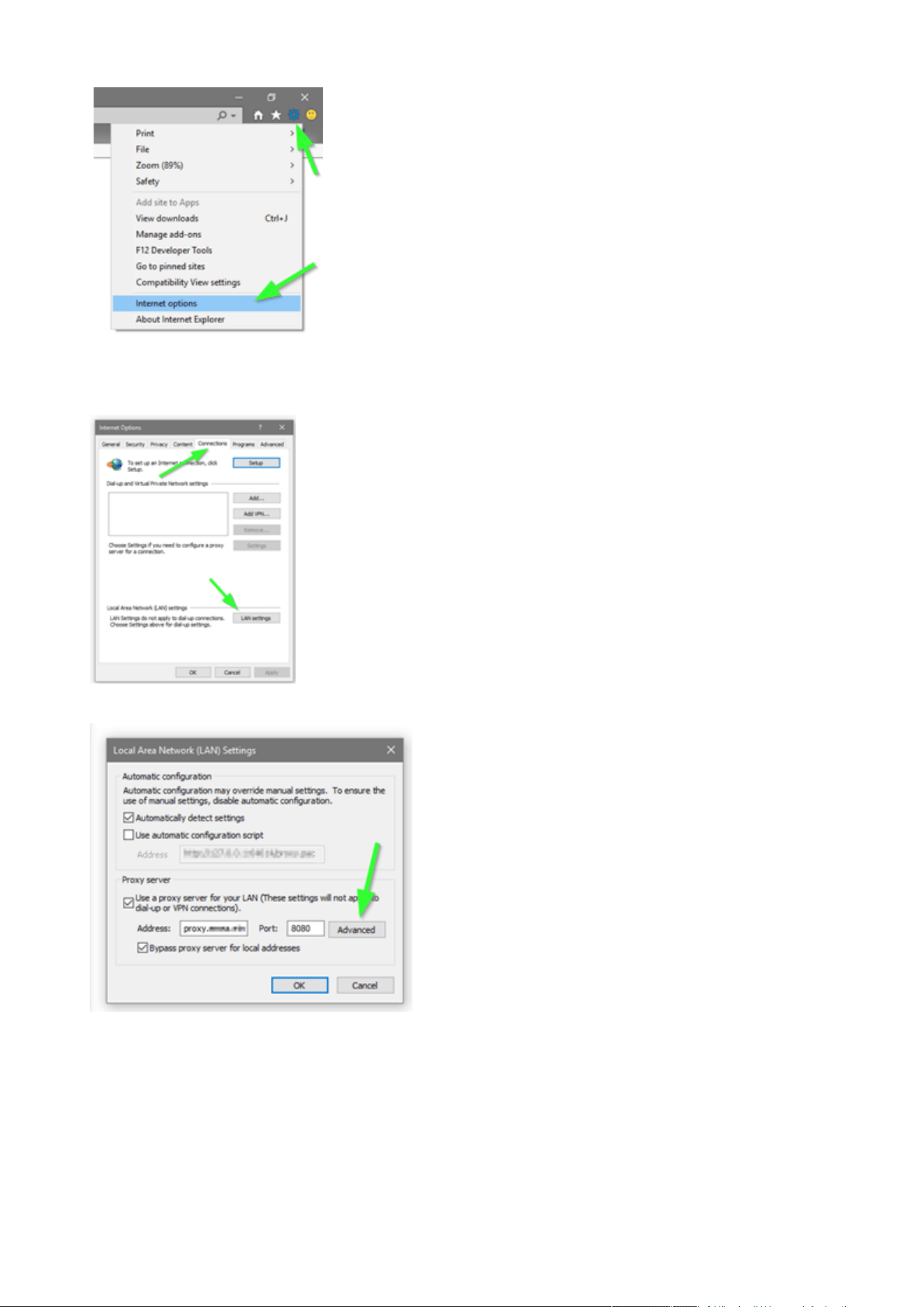
2.4.5 Modifying the Proxy exception list
To connect to the Network Module via a USB cable and your system uses a Proxy server to connect to the internet, the proxy
settings can reject the IP address 169.254.0.1.
The 169.254. * Sequence is used to set up communication with devices via a physical connection.
To activate this connection, exceptions will have to be made in the proxy settings.
Open Internet Explorer
Navigate to settings, Internet options;
Changing network parameters may cause the card to become unavailable remotely. If this happens it can only be
reconfigured locally through USB.
You can see this list of available commands by typing in the CLI:
?
You can see the help by typing in the CLI:
help
Accessing the Network Module
Installing the Network Management Module – 23
•
•
•
•
Select the Connections tab
Press LAN Settings
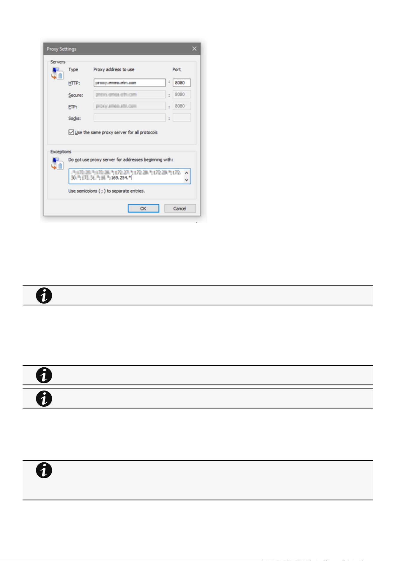
Press ADVANCED
Add the address 169.254. *
Configuring Modbus
Installing the Network Management Module – 24
•
•
•
•
•
•
•
Press OK.
Close Internet Explorer and re-open it.
Now you can access the address 169.254.0.1 with Internet Explorer and any other browser.
2.5 Configuring Modbus
2.5.1 Configuring the communication parameters
Access the web interface through Network or RNDIS
Navigate to Contextual help>>>Settings>>>Modbusand set the communication parameters to the desired settings.
2.5.2 Available maps
Access the web interface through Network or RNDIS
Navigate to Contextual help>>>Settings>>>Modbus and press theSupported MAPsbutton to download the MAPs.
This section is only for the Modbus Network Module INDGW
For Modbus RTU configuration refer to the sectionContextual help>>>Settings>>>Modbus>>>Modbus
RTU.
For Modbus TCP configuration refer to the sectionContextual help>>>Settings>>>Modbus>>>Modbus TCP.
File is generated in real time and will take into account the device capabilities and values at the time of the
generation.
Table in the downloaded file will show all possible registers, only the one showing Available equal to True will be
supported by your system.The units used on Modbus map belong to the International System of Units,
temperatures are expressed in Kelvin for example.

Configuring Modbus
Installing the Network Management Module – 25
•
•
•
•
•
•
•
•
•
•
•
•
•
•
•
•
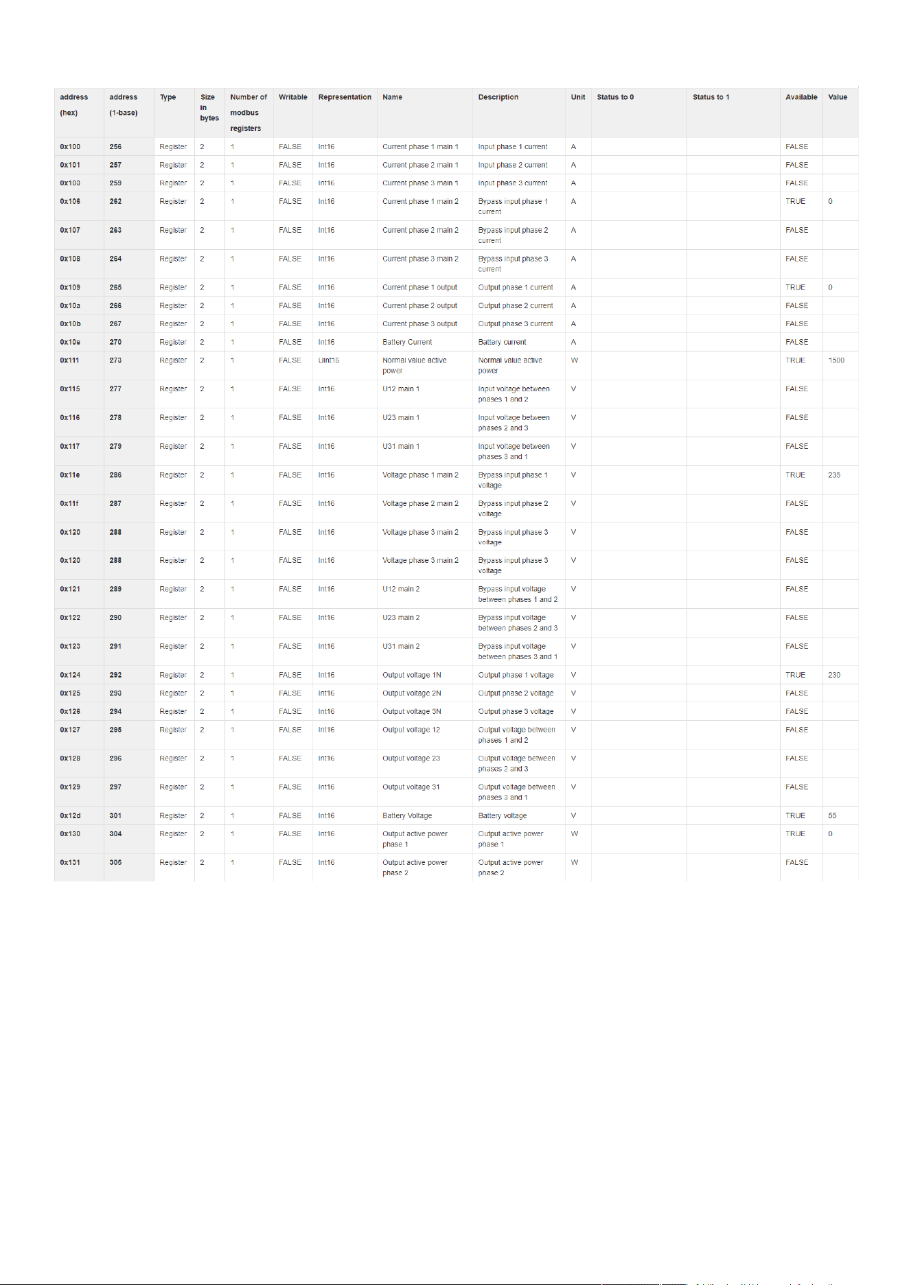
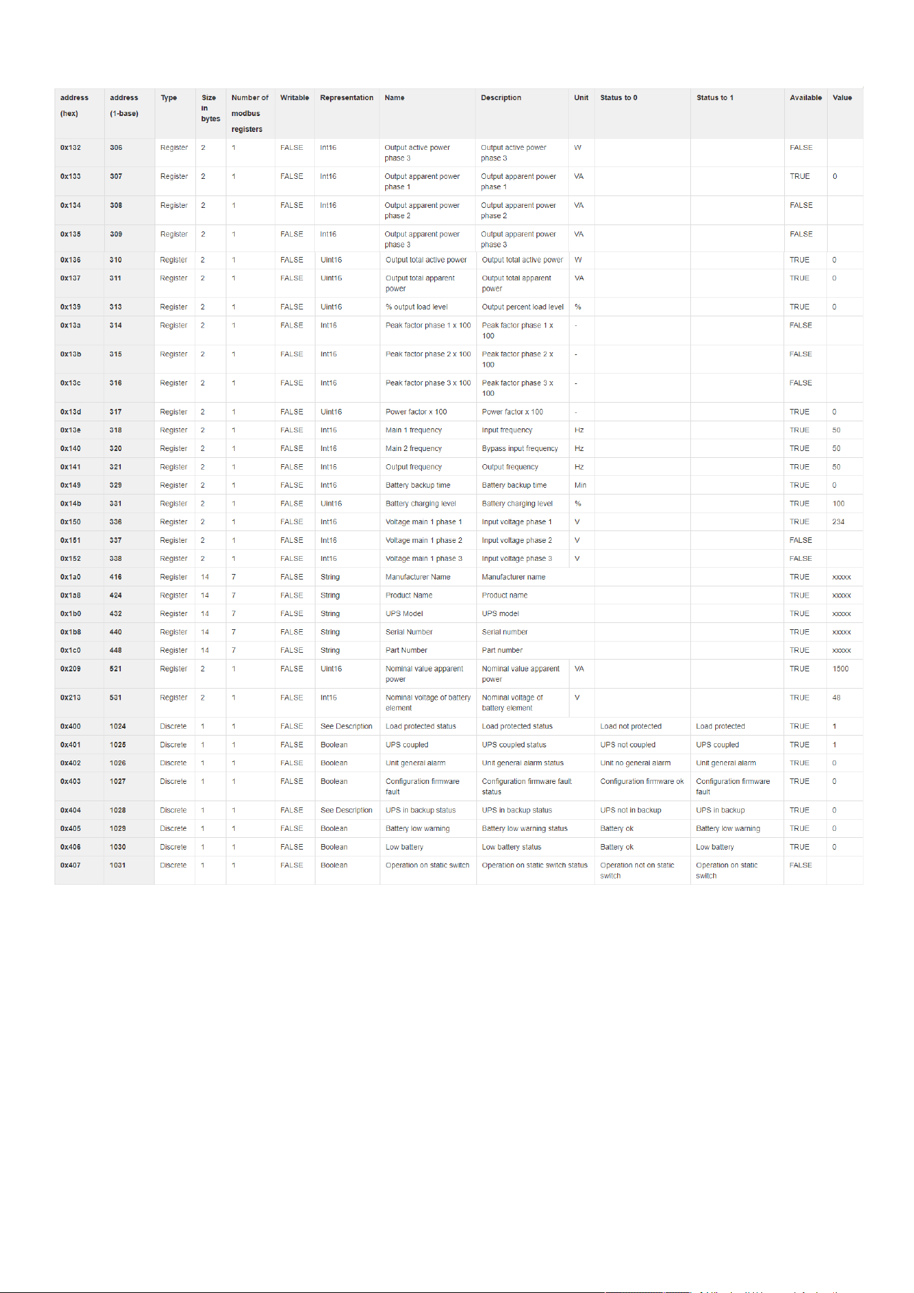
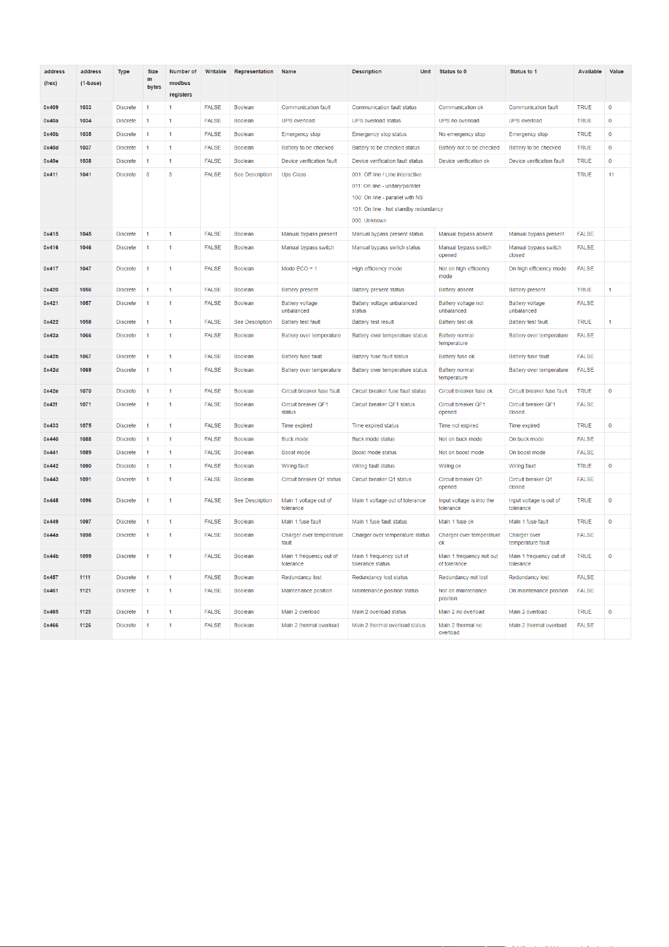
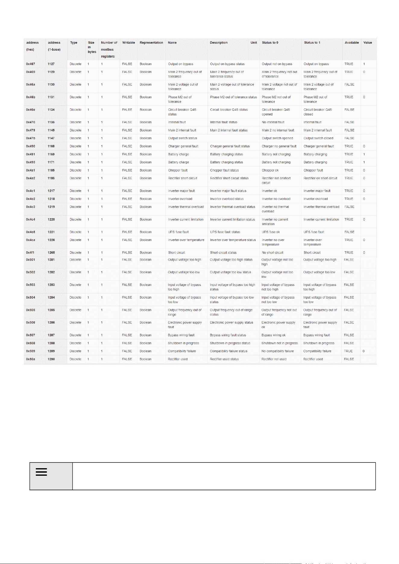
2.5.2.1 Mapping table content
address (hex): register address in hexadecimal
address (1-base): register address in 1-base format
Type: Register/Discrete
Size in bytes
Number of modbus registers
Writable: True/False
Representation: Int16/Uint16/String/Boolean/...
Name
Description
Unit (Kelvin, A, V, W, VA,%, Hz, min, ...)
Status to 0: status when the discrete equal 0
Status to 1:status when the discrete equal 1
Available: True/False –Shows if the register is available on current device
Value: Shows current value of the register on current device
2.5.3 Adding a Custom MAP
On top of the available MAPs, navigating through the Settings > Industrial Protocols > Modbus Mapping Configuration you can add
a new MAP by clicking the "new" button.
2.5.4 Modbus communication monitoring tool
Access the CLI through SSH or the Serial terminal emulation
Get available commands by typing ? in the CLI
CLI commands can be used to retrieve Modbus communication statistics,
seeInformation>>>CLI>>>modbus_statisticssectionfor more details.
2.5.5 Example of supported Modbus mapping
The following table is an example of the mapping information that can be retrieved in the Modbus settings by pressing the
Supported MAPs button.
For an example of supported Modbus mapping, navigate to Installing the Network Management
Module>>>Configuring Modbus>>>Example of supported Modbus mapping.
Configuring Modbus
Installing the Network Management Module – 26
Configuring Modbus
Installing the Network Management Module – 27
Configuring Modbus
Installing the Network Management Module – 28
Configuring the Network Module settings
Installing the Network Management Module – 29
2.6 Configuring the Network Module settings
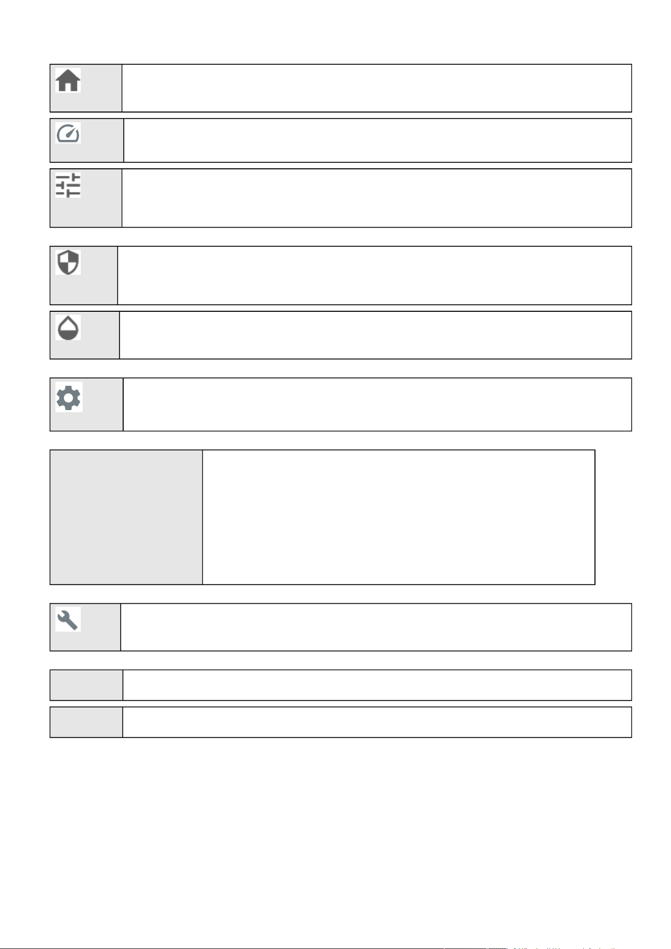
Use the web interface to configure the Network Module. The main web interface menus are described below:
2.6.1 Menu structure
Extend menu display.
Configuring the Network Module settings
Installing the Network Management Module – 30
Home:Overview and status oftheDevice(Active alarms, Outlet status, ...).
Meters:Power quality meters and logs.
Controls:Device and outlets control.
Protection:Agents list, Agents shutdown sequencing, Shutdown on power outage.
Environment: Commissioning/Status, Alarm configuration, Information.
Settings:Network Module settings.
Unable to render include or excerpt-
include. Could not retrieve page.
or
Unable to render include or excerpt-
include. Could not retrieve page.
Device settings: General information, Settings.
Maintenance:Firmware, Services, Resources, System logs.
FW Display Network module firmware version.
Time Display Network Module local time (not the UTC time).

Login page
Contextual help of the web interface – 31
•
•
3 Contextual help of the web interface
3.1 Login page
The page language is set toEnglish
by default but can be switched tobrowser language when it is managed.
After navigating to theassigned IP address, accept the untrusted certificate on the browser.
3.1.1 Logging in for the first time
3.1.1.1 1.Enter default password
As you are logging into the Network Module for the first time you must enter the factory set default username and password.
Username = admin
Password = admin
3.1.1.2 2. Change default password
Changing the default password is mandatory and requested in a dedicated window.
Enter your current password first, and then enter the new password twice.
Follow the password format recommendations on the tooltip in order to define a secure password.
3.1.1.3 3. Accept license agreement
On the next step, License Agreement is displayed.
Read and accept the agreement to continue.
3.1.2 Specifics
3.1.3 Troubleshooting
How do I log in if I forgot my password?
1.
2.
Accounts with identical names
When an user attempt to log with a user name that exist both locally & remotely, then only the local account can
successfully be logged in by default.
Two options for the remote user to successfully log in
You can use a prefix to access the remote account. For example ldap\johndoe or radius\johndoe depending
on the remote configuration you set in the card.
Change the user name of the local account
Home
Contextual help of the web interface – 32
•
•
•
•
•
•
•
•
•
Action
Askyour administrator for password initialization.
If you are the mainadministrator, yourpasswordcan be reset manually by following steps described in the Servicing
the Network Management Module>>>Recovering main administrator password .
Web user interface is not up to date after a FW upgrade
Symptom
After an upgrade:
The Web interface is not up to date
New features of the new FW are not displayed
An infinite spinner is displayed on a tile
Possible causes
The browser is displaying the Web interface through the cache that contains previous FW data.
Action
Empty the cache of your browser using F5 or CTRL+F5.
3.1.3.1 For other issues
3.2 Home
The Home screen providesstatus informationfor the deviceincluding key measures andactive alarms.
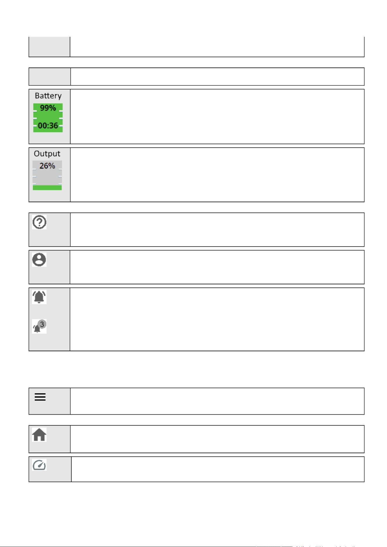
3.2.1 Header structure
Name Displays the Network module name.
Device name Displays by default the Device model or the system name if filled in the section Contextual
help>>>Maintenance>>>System information.
Shortcut to the Device details:
Name
Location
Model
P/N
For details on other issues, see the Troubleshooting section.
Home
Contextual help of the web interface – 33
•
•
S/N
FW version
Device status Displays if the Device is Online, On bypass, On battery...
Displays the battery level (in %) and the remaining backup time.
Output load level
Help:Opens full documentation in a separate browser page.
Profile:Displays user profile, password change, account information, logout and legal information.
Alarms:Open alarm page and displays the number of active alarms.
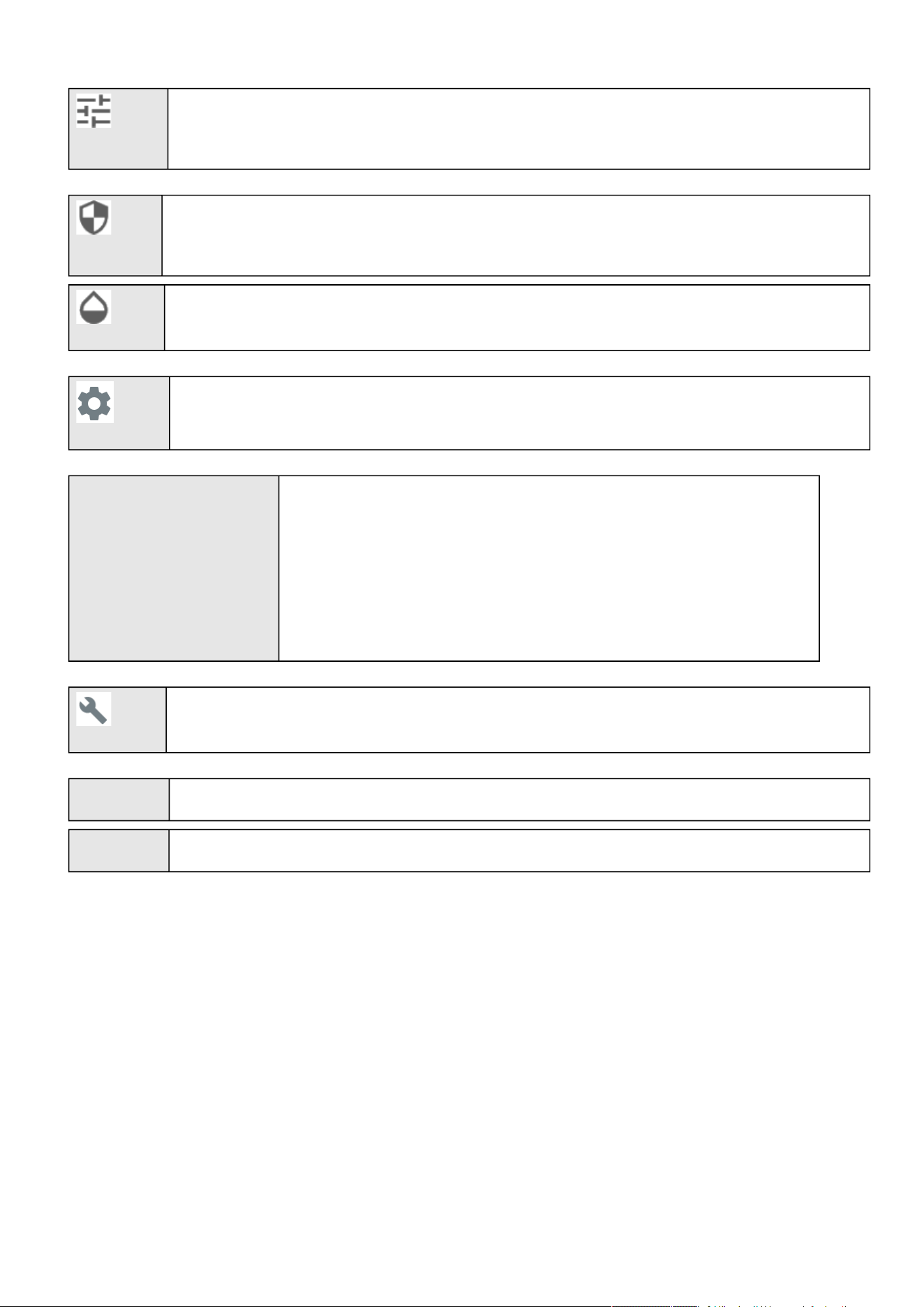
3.2.2 Menu structure
Extend menu display.
Home:Overview and status oftheDevice(Active alarms, Outlet status, ...).
Meters:Power quality meters and logs.
Home
Contextual help of the web interface – 34
Controls:Device and outlets control.
Protection:Agents list, Agents shutdown sequencing, Shutdown on power outage.
Environment: Commissioning/Status, Alarm configuration, Information.
Settings:Network Module settings.
Unable to render include or excerpt-
include. Could not retrieve page.
or
Unable to render include or excerpt-
include. Could not retrieve page.
Device settings: General information, Settings.
Maintenance:Firmware, Services, Resources, System logs.
FW Display Network module firmware version.
Time Display Network Module local time (not the UTC time).
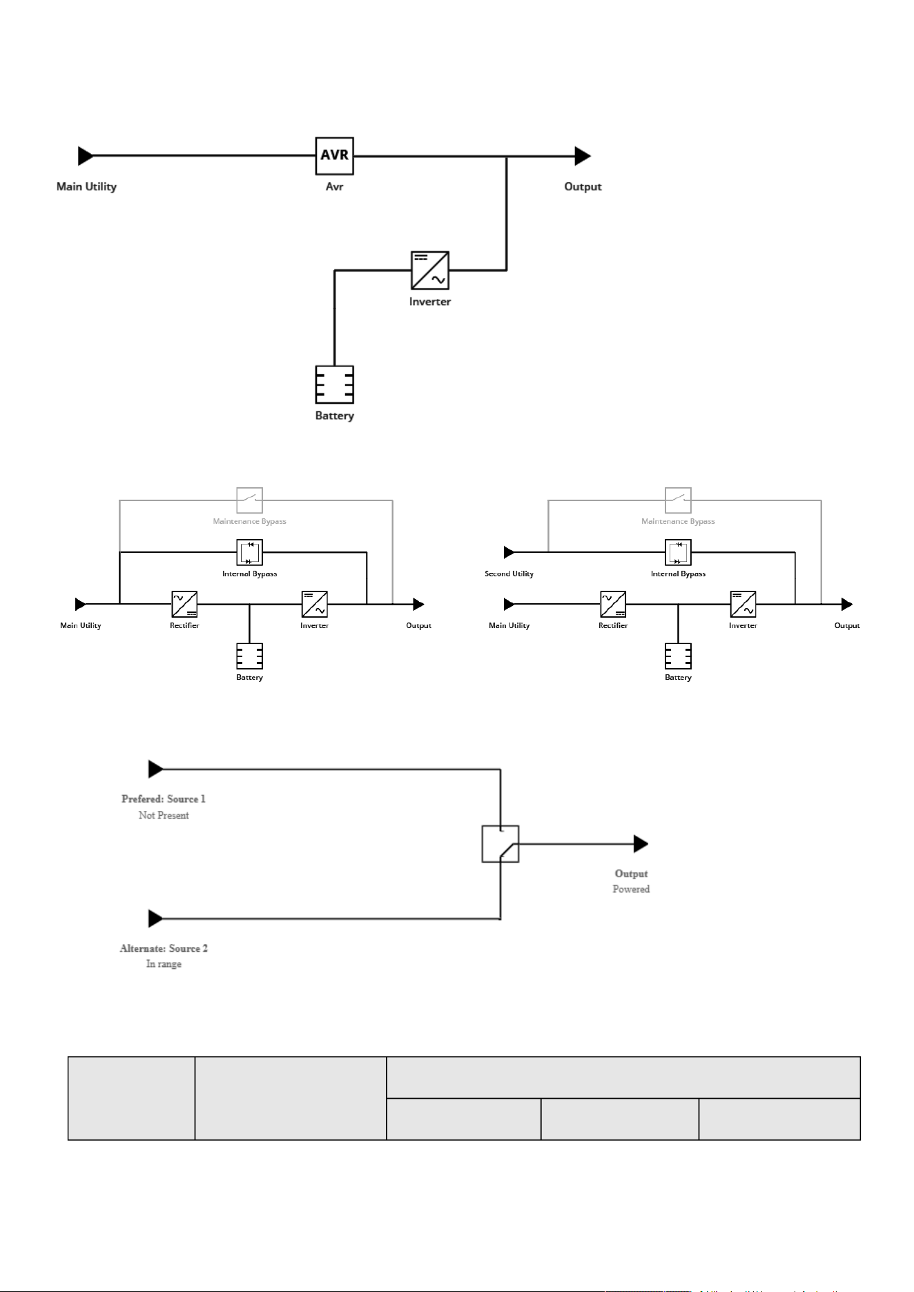
3.2.3 Energy flow diagram
Home
Contextual help of the web interface – 35
3.2.3.1 Line interactive UPS
3.2.3.2 Online UPS
3.2.3.3 ATS
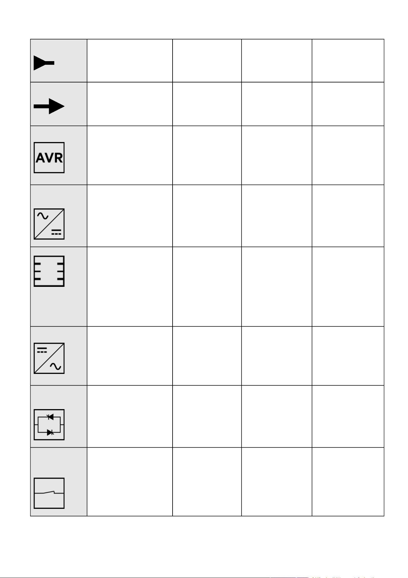
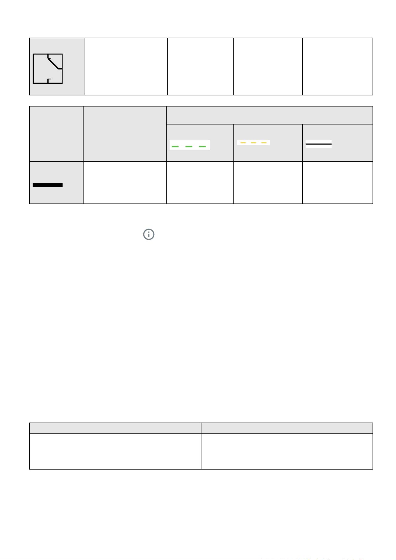
3.2.3.4 Diagram elements description
Description and
symbols
Description Possible states below the symbol
Good Warning Fault
Home
Contextual help of the web interface – 36
Input Main utility input. In range Out of nominal range
Output Output of the UPS. Protected
Powered
In overload
Not protected
In short circuit
AVR device The equipment is protected and
powered through an AVR device.
Normal mode
Buck mode
Boost mode
In overload
Rectifier Rectifier: convert AC power to
DC power.
Normal
HE mode (ready) / ESS
mode (ready)
In overload In short circuit
In fault
Battery/Charger Battery and internal battery
charger.
Battery:
OK
Charger:
Charging
Floating
Resting
Off
Battery:
End of life
Battery:
In fault
Charger:
In fault
Not present
Inverter Inverter: convert DC power to
AC power.
Normal In overload In short circuit
In fault
Internal bypass Automatic bypass. Powered (standby, auto
bypass, forced bypass,
HE mode, ESS mode)
In overload In fault
Maintenance bypass
(optional)
Maintenance bypass closed. Maintenance
Home
Contextual help of the web interface – 37
•
•
•
•
•
•
•
•
•
•
ATS device The equipment is powered
through an ATS device.
Description and
symbols
Description Possible states
Green Orange Black
Wiring Electrical connection between
blocks.
Energy flow In overload
Out of nominal range
No energy
Unknown
3.2.3.5 Details
To access the device details, press theicon:
Thisview provides a summary of device identification information and nominal values:
Name
Model
P/N
S/N
Location
Firmware version
Input Voltage
Input Frequency
Output Voltage
Output Frequency
TheCOPY TO CLIPBOARDbutton will copy the information toyour clipboard.
For example, you can copy and paste information into an email.
3.2.3.6 Show measures
Provides input and output measures on the synoptic.
3.2.3.6.1 Example #1
Single input source with 1 phase in and 1 phase out:
Input measures Output measures
Voltage (V)
Current (A)
Frequency (Hz)
Voltage (V)
Current (A)
Frequency (Hz)
3.2.3.6.2 Example #2
Dual input sources with 3 phases in and 3 phases out

Home
Contextual help of the web interface – 38
•
•
Input measures (main and secondary) Output measures
Phase #1
Voltage (V)
Current (A)
Phase #2
Voltage (V)
Current (A)
Phase #3
Voltage (V)
Current (A)
Phase #1
Voltage (V)
Current (A)
Phase #2
Voltage (V)
Current (A)
Phase #3
Voltage (V)
Current (A)
Load (W)
Load (%)
Frequency (Hz) Frequency (Hz)
3.2.4 Outlet status
Providesthe status of the UPS outlets (ON/OFF) by load segmentation:
Status (ON/OFF— Protected/Not protected/Not powered)
Load level (W)– availability depending on the UPS model
Note:To access Controls menu, press theicon:
3.2.5 Active Alarms
Only active alarms are displayed, the Alarmsicon will alsodisplay the number of active alarms.
Alarms are sorted by date,alert level, time, anddescription.
Note:To seethe alarm history,press the icon:
3.2.6 Environment
UPS ambient temperature is displayed if available.
Sensor status and data are displayed if available,MIN-MAX shows the minimal and maximal temperature or humidity measured by
the sensor.
Note:To seedetailed sensor data,press theicon:
Note: Load segmentations allow non-priority equipment to automatically power down during an extended power
outage to keep battery runtime on essential equipment.
This feature is also used toremote reboot and sequential startservers to restrict inrush currents.
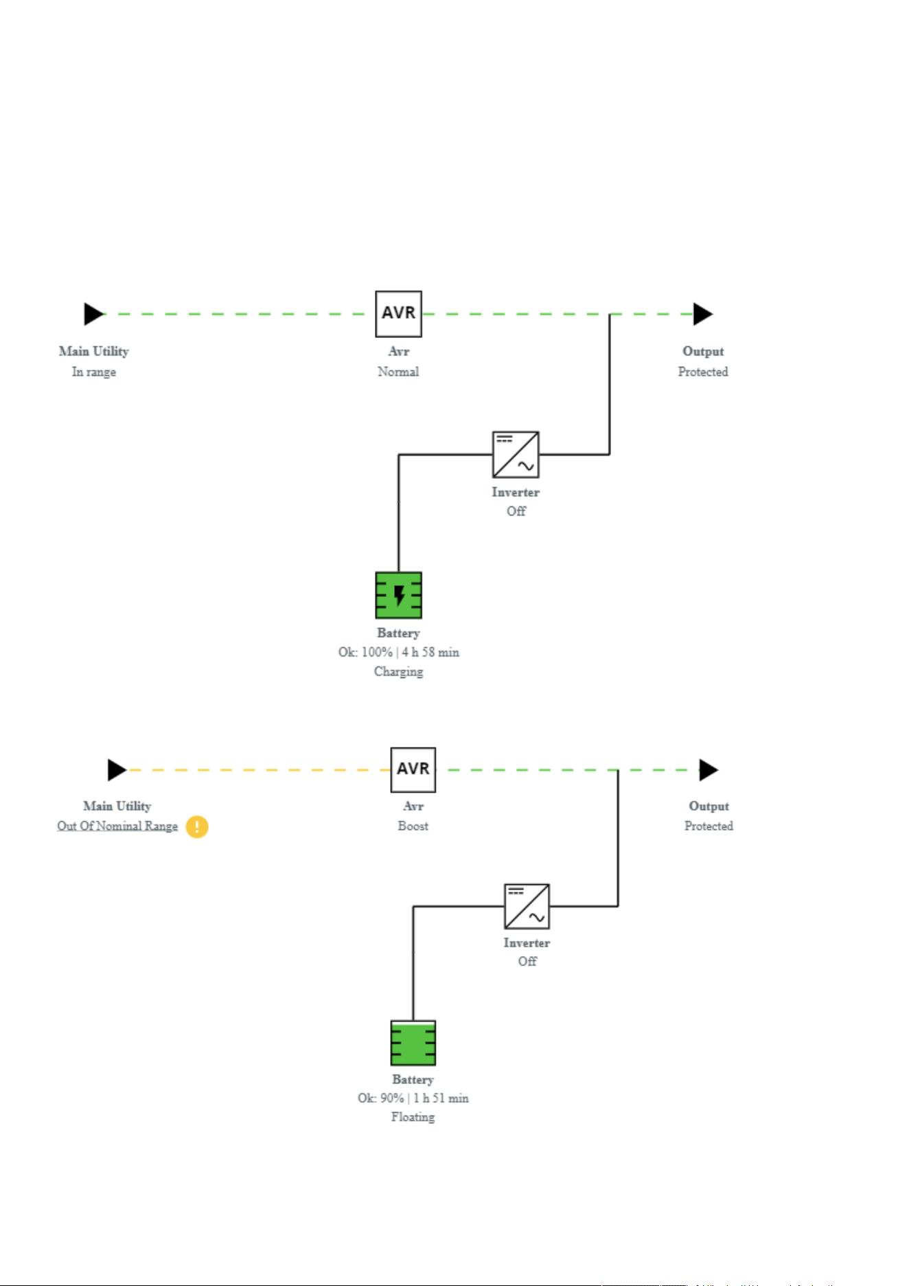
Home
Contextual help of the web interface – 39
3.2.7 Specifics
3.2.8 Energy flow diagram examples
3.2.8.1 Line interactive UPS
3.2.8.1.1 Normal mode
3.2.8.1.2 Buck/Boost mode
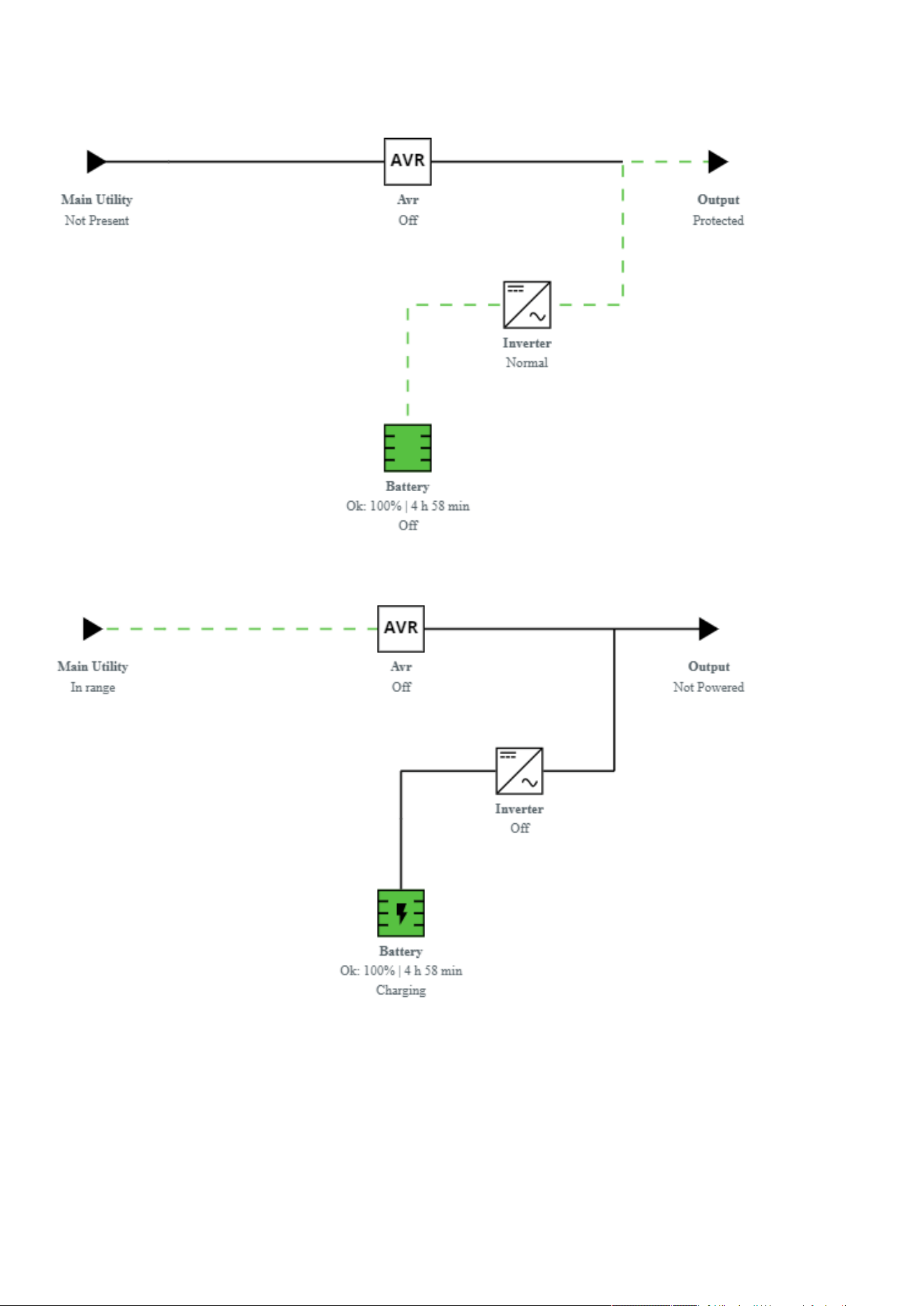
Home
Contextual help of the web interface – 40
3.2.8.1.3 Battery mode
3.2.8.1.4 Off mode
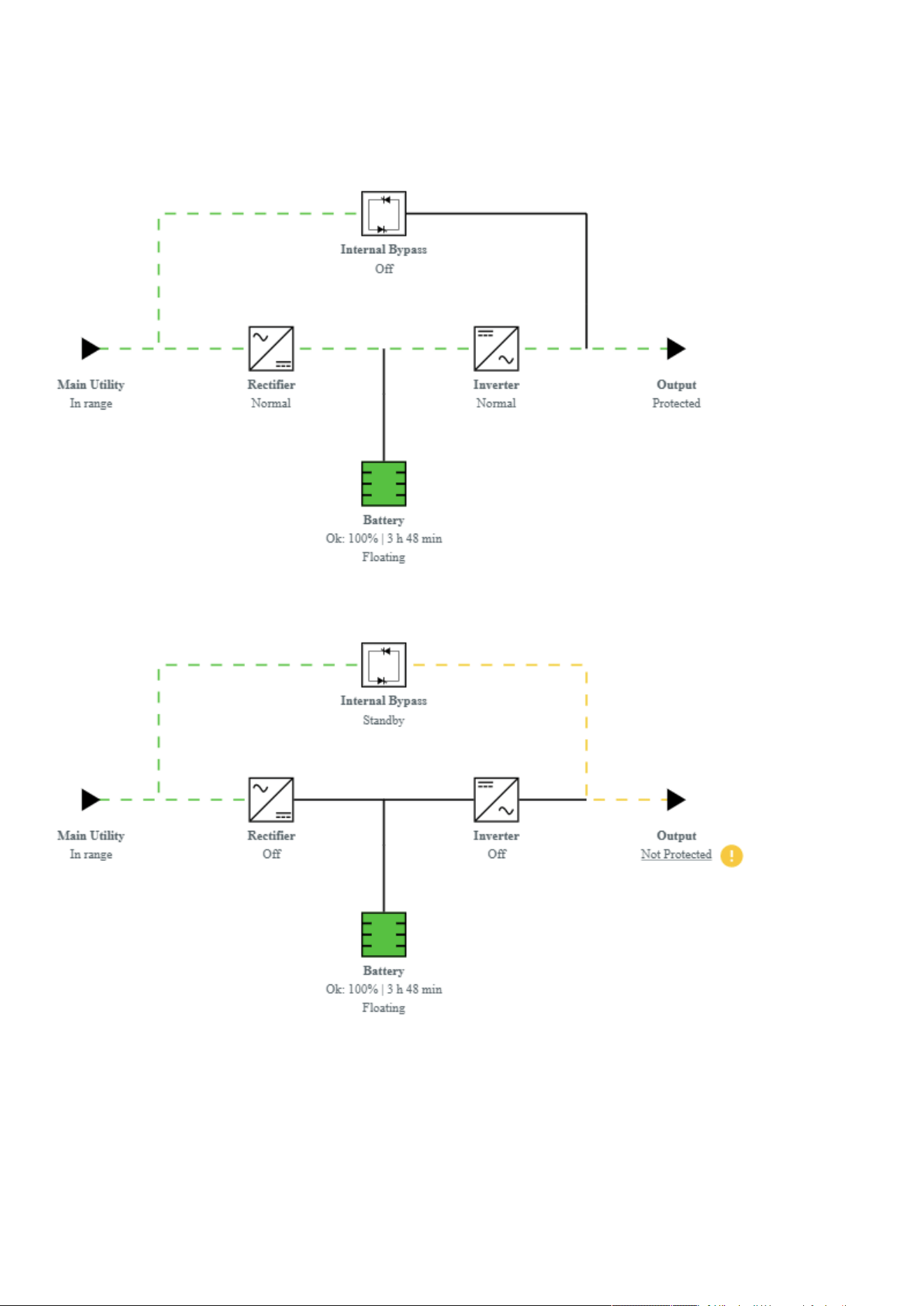
Home
Contextual help of the web interface – 41
3.2.8.2 Online UPS with single input source
3.2.8.2.1 Online mode
3.2.8.2.2 Bypass mode
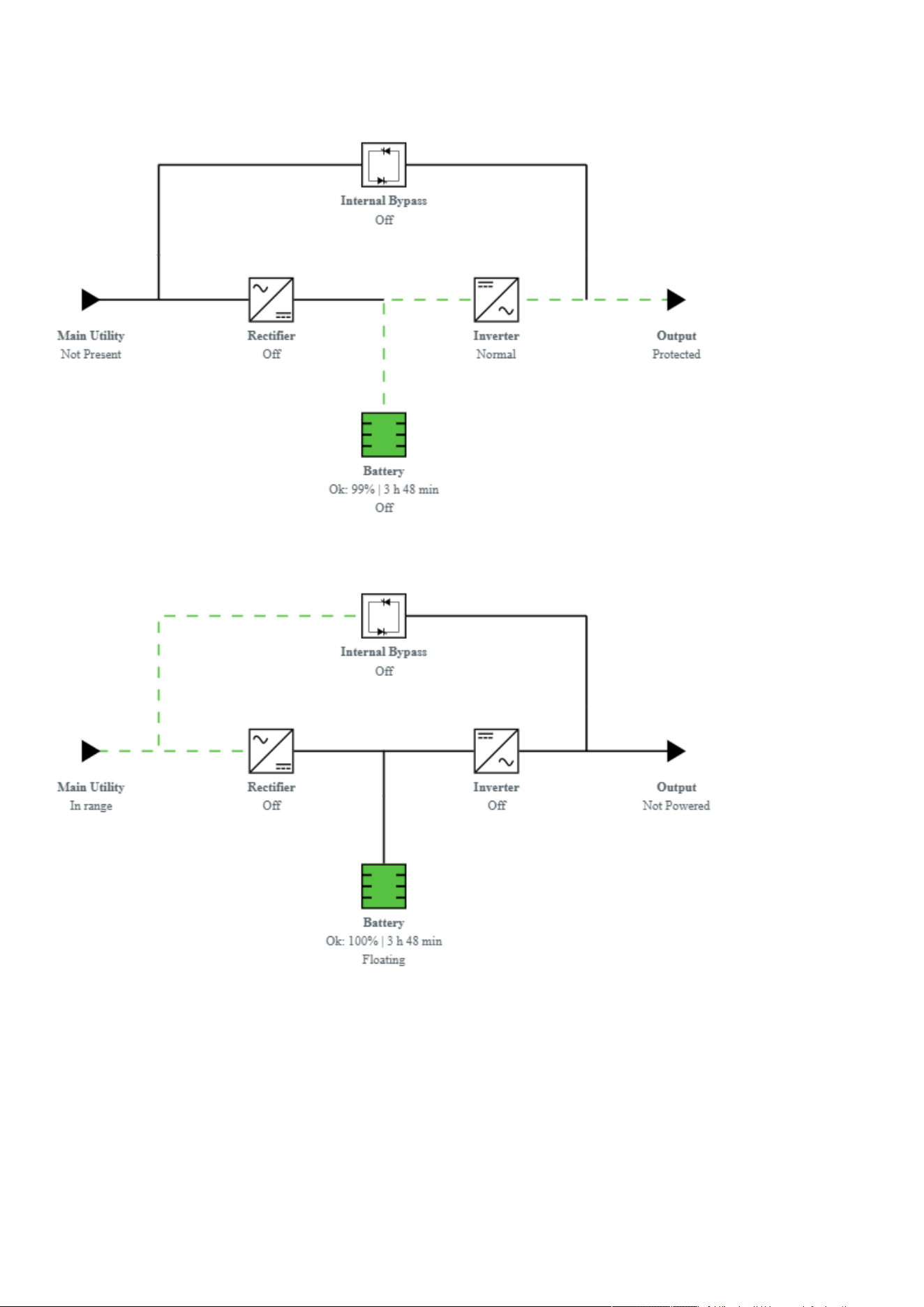
Home
Contextual help of the web interface – 42
3.2.8.2.3 Battery mode
3.2.8.2.4 Off mode
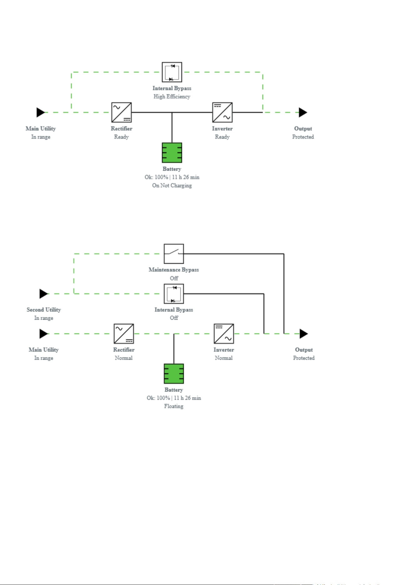
Home
Contextual help of the web interface – 43
3.2.8.2.5 HE mode / ESS mode
3.2.8.3 Online UPS with dual inputs sources and Maintenance bypass
3.2.8.3.1 Online mode
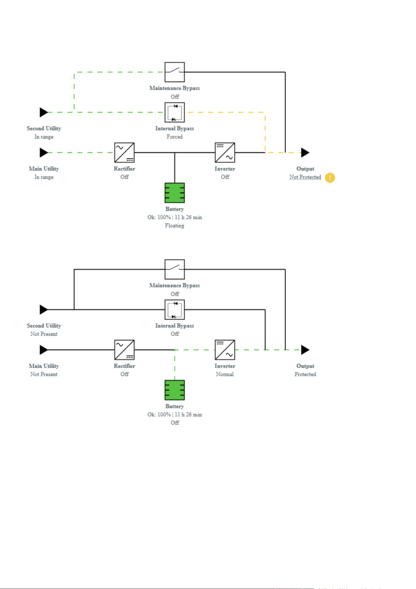
Home
Contextual help of the web interface – 44
3.2.8.3.2 Bypass mode
3.2.8.3.3 Battery mode
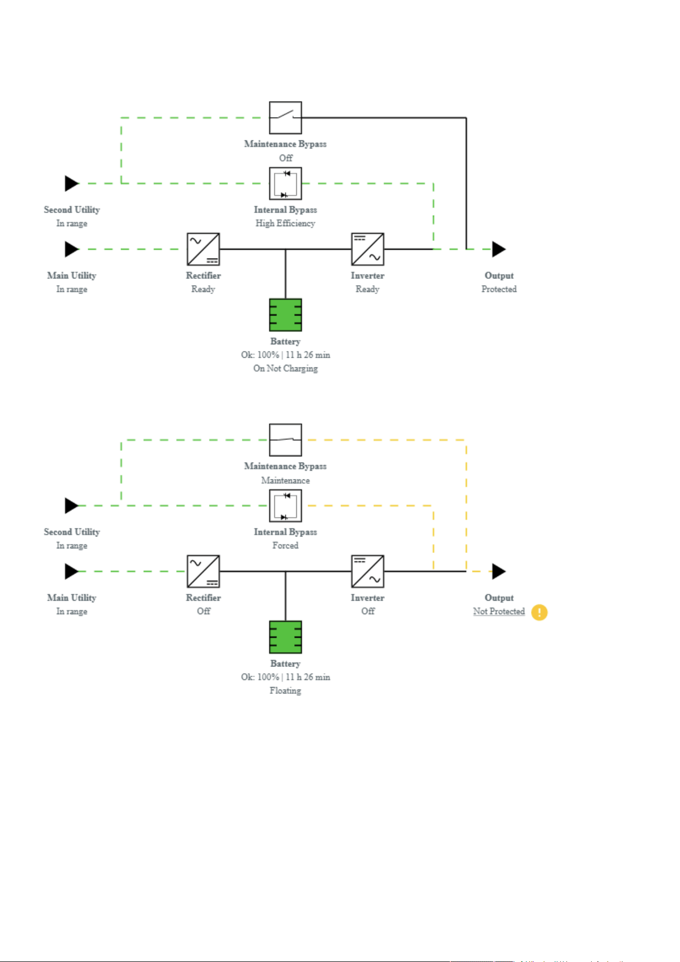
Home
Contextual help of the web interface – 45
3.2.8.3.4 HE mode / ESS mode
3.2.8.3.5 Maintenance bypass mode
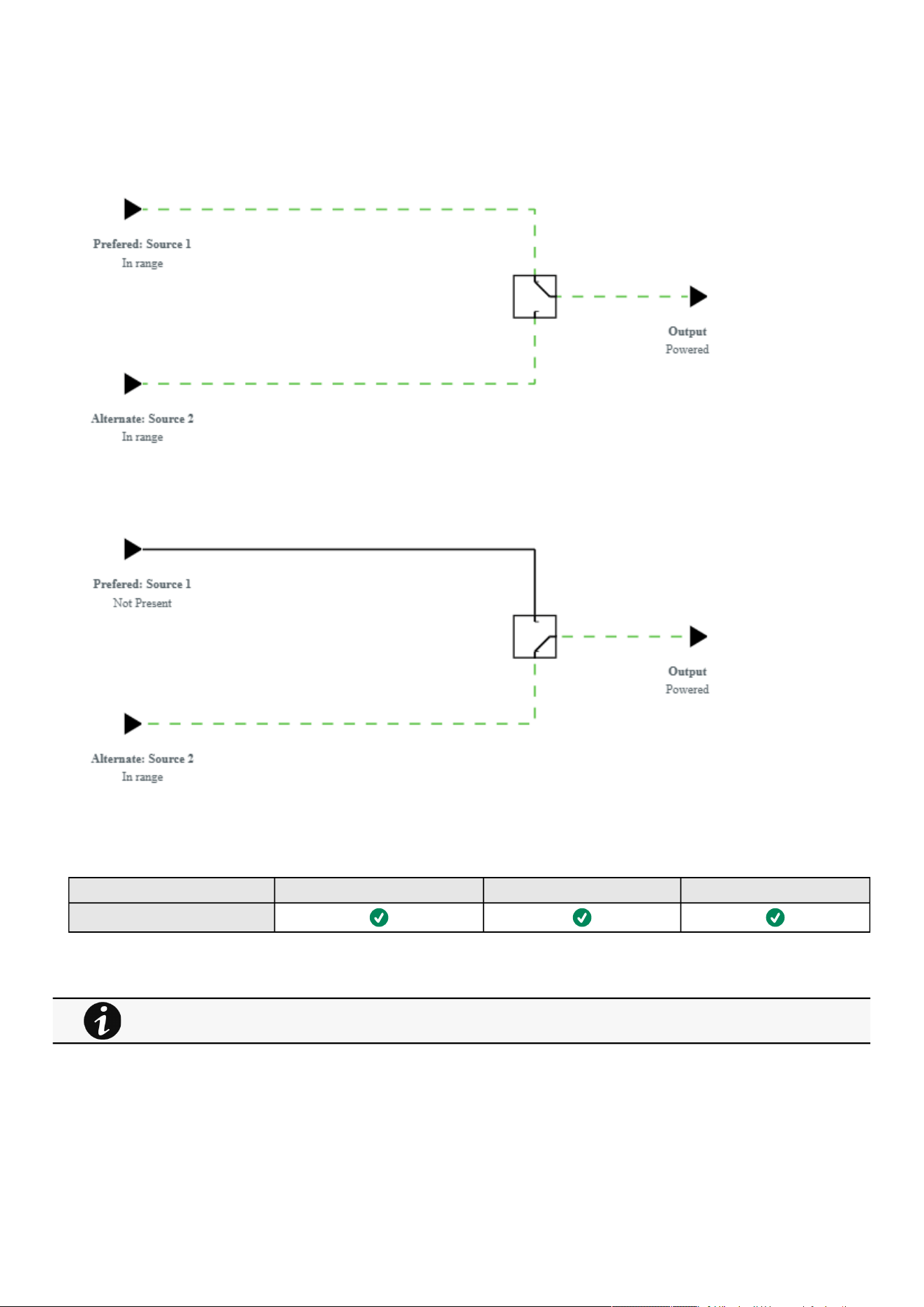

Meters
Contextual help of the web interface – 47
•
•
•
•
•
•
•
•
•
•
•
•
•
•
•
•
•
•
•
•
•
•
•
•
3.3 Meters
3.3.1 Measures
3.3.1.1 Main utility input
Displays the product main utility measures.
Current (A)
Voltage (V)
3.3.1.2 Second utility input (if available)
If presents, displays the product second utility measures.
Current (A)
Voltage (V)
3.3.1.3 Output
Voltage (V)
Power (W)
Current (A)
3.3.2 Battery
3.3.2.1 Battery status
Battery status section is an overviewof the battery information.
3.3.2.1.1 Overview/Environment
Type
EBM count
Nominal capacity
Nominal voltage
Capacity remaining
Runtime
State
Recommended replacement date
State of health
Voltage
Current
Temperature
Min cell voltage
Max cell voltage
Number of cycles
Min temperature
Max temperature
•
•
•
Gauge color code:
Green: Value inside thresholds.
Orange/Red: Value outside thresholds.
Blue: No thresholds provided by the device.
The information displayed depends on the device.

Meters
Contextual help of the web interface – 48
•
•
•
•
•
•
•
•
•
•
•
•
•
•
•
•
•
•
•
•
•
•
•
•
BMS state
3.3.2.2 Battery health
Battery health section provides status of the battery andallow to launch a battery test.
The status reflects thelast completed battery test result,as well as itscritical status (color) and completion time.
Pass
Warning
Fail
Unknown
3.3.2.2.1 Commands
Launch test
button is disabled if a battery test is already in progress or scheduled.
TheAbort test
button is enabled only when a test is in progress or scheduled.
3.3.2.2.2 Pending action
The pending action reflects thebattery test status.
None
Scheduled
In progress
Aborted
Done
3.3.3 Data logs
3.3.3.1 Logs
This log configuration allows to define the log acquisition frequency of the Device measures only.
3.3.3.1.1 Download
Press the icon on the top right to download the Device log file.
If available, possible measures are listed below:
Input Voltage (V)
Input Frequency (Hz)
Bypass Voltage (V)
Bypass Frequency (Hz)
Output Voltage (V)
Output Frequency (Hz)
Output Current (A)
Output Apparent Power (VA)
Output Active Power (W)
Output Power Factor
Output Percent Load (%)
Battery Voltage (V)
Battery Capacity (%)
Battery Remaining Time (s)
The sensors measures logs acquisition is not settable and done every minutes. Sensors measures logs are
accessible in Environment menu.
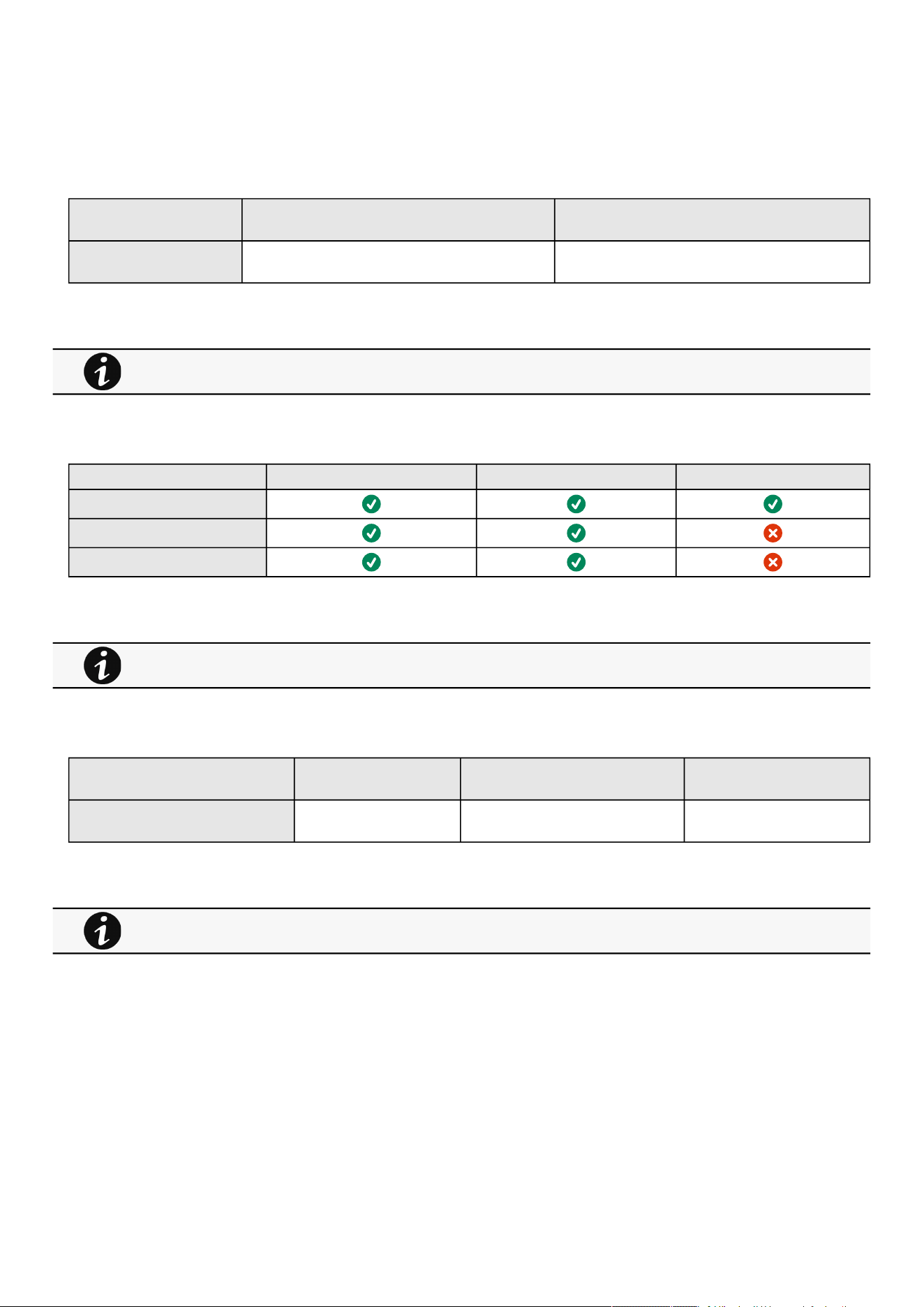
Controls
Contextual help of the web interface – 49
3.3.3.2 Specifics
3.3.4 Default settings and possible parameters - Meters
Default setting Possible parameters
Meters/Logs Log measures every—60s Log measures every — 3600s maximum
3.3.4.1 For other settings
3.3.5 Access rights per profiles
Administrator Operator Viewer
Meters
Battery health: Launch test/Abort
Logs configuration
3.3.5.1 For other access rights
3.3.6 Save and Restore
SRR section Settings Possible values
Logs measure periodicity [time in seconds]
3.3.6.1 Additional information
3.4 Controls
3.4.1 Entire UPS
Controls are displayed for the entire UPS, and not for specific outlet options.
The table in this section displays UPS status, the associated commands (on/off), and the pending action.
For other settings, see the Information>>>Default settings parameters section.
For other access rights, see the Information>>>Access rights per profiles section.
For details on Save and Restore, see the Save and Restore section.

Controls
Contextual help of the web interface – 50
•
•
•
•
•
•
•
•
•
•
3.4.1.1 Status
Reflects the current mode of the UPS.The following is a list of potential table values that are displayed based on the UPS topology.
On— Protected/Not protected
Off— Not powered/Not protected
3.4.1.2 Commands
A setof commands are available and activated when one of the followingbuttons is pressed.A confirmation window appears.
Safe OFF
This will shut off the load. Protected applications will be safely powered down.
This control is available only if the status is not OFF and if there are no active commands running.
Safe reboot
This will shut off and then switch ON the load. Protected applications will be safely powered down.
This control is available only if the status is not OFF and if there are no active commands running.
Switch ON
This will switch ON the load or turn ON the online UPS.
This control is available when the status is OFF, if there are no active commands running and if the Online UPS is on bypass.
3.4.1.3 Pending action
Displays the delay before shutdown and delays before startup.
3.4.2 Outlets - Group 1/ Group 2
Load segmentations allow, battery runtime to remain on essential equipment and automatically power down non-priority equipment
during an extended power outage.
This feature is also used for remote reboot and the sequential start of servers to restrict inrush currents.
3.4.2.1 Status
It reflects the current outlet status.
On — Protected/Not protected
Off — Not powered
3.4.2.2 Commands
A setof commands are available and activated when one of the following buttons is pressed.A confirmation window appears.
Safe OFF
This will shut off the load connected to the associated load segment. Protected applications are safely powered down.
This control is available only if the status is not OFF and if there are no active commands running.
Safe reboot
This will power down and then switch ON the load connected to the associatedload segment. Protected applications are
safely powered down.
This control is available only if the status is not OFF and if there are no active commands running.
Switch ON
This will switch ON the load connected to the associatedload segment.
This control is available when status is OFFand if there are no active commands running.

Controls
Contextual help of the web interface – 51
•
•
•
•
•
•
•
3.4.2.3 Pending action
Displays the delay before shutdown and delay before startup.
3.4.3 Specifics
3.4.4 Group
3.4.4.1 Entire UPS
Controls are displayed for the entire UPS, and not for specific outlet options.
The table in this section displays UPS status, the associated commands (on/off), and the pending action.
3.4.4.1.1 Status
Reflects the current mode of the UPS.The following is a list of potential table values that are displayed based on the UPS topology.
On— Protected/Not protected
Off— Not powered/Not protected
3.4.4.1.2 Commands
A setof commands are available and activated when one of the followingbuttons is pressed.A confirmation window appears.
Safe OFF
This will shut off the load. Protected applications will be safely powered down.
This control is available only if the status is not OFF and if there are no active commands running.
Safe reboot
This will shut off and then switch ON the load. Protected applications will be safely powered down.
This control is available only if the status is not OFF and if there are no active commands running.
Switch ON
This will switch ON the load or turn ON the online UPS.
This control is available when the status is OFF, if there are no active commands running and if the Online UPS is on bypass.
3.4.4.1.3 Pending action
Displays the delay before shutdown and delays before startup.
3.4.4.2 Outlets - Group 1/ Group 2
Load segmentations allow, battery runtime to remain on essential equipment and automatically power down non-priority equipment
during an extended power outage.
This feature is also used for remote reboot and the sequential start of servers to restrict inrush currents.
3.4.4.2.1 Status
It reflects the current outlet status.
On — Protected/Not protected
Off — Not powered
3.4.4.2.2 Commands
A setof commands are available and activated when one of the following buttons is pressed.A confirmation window appears.
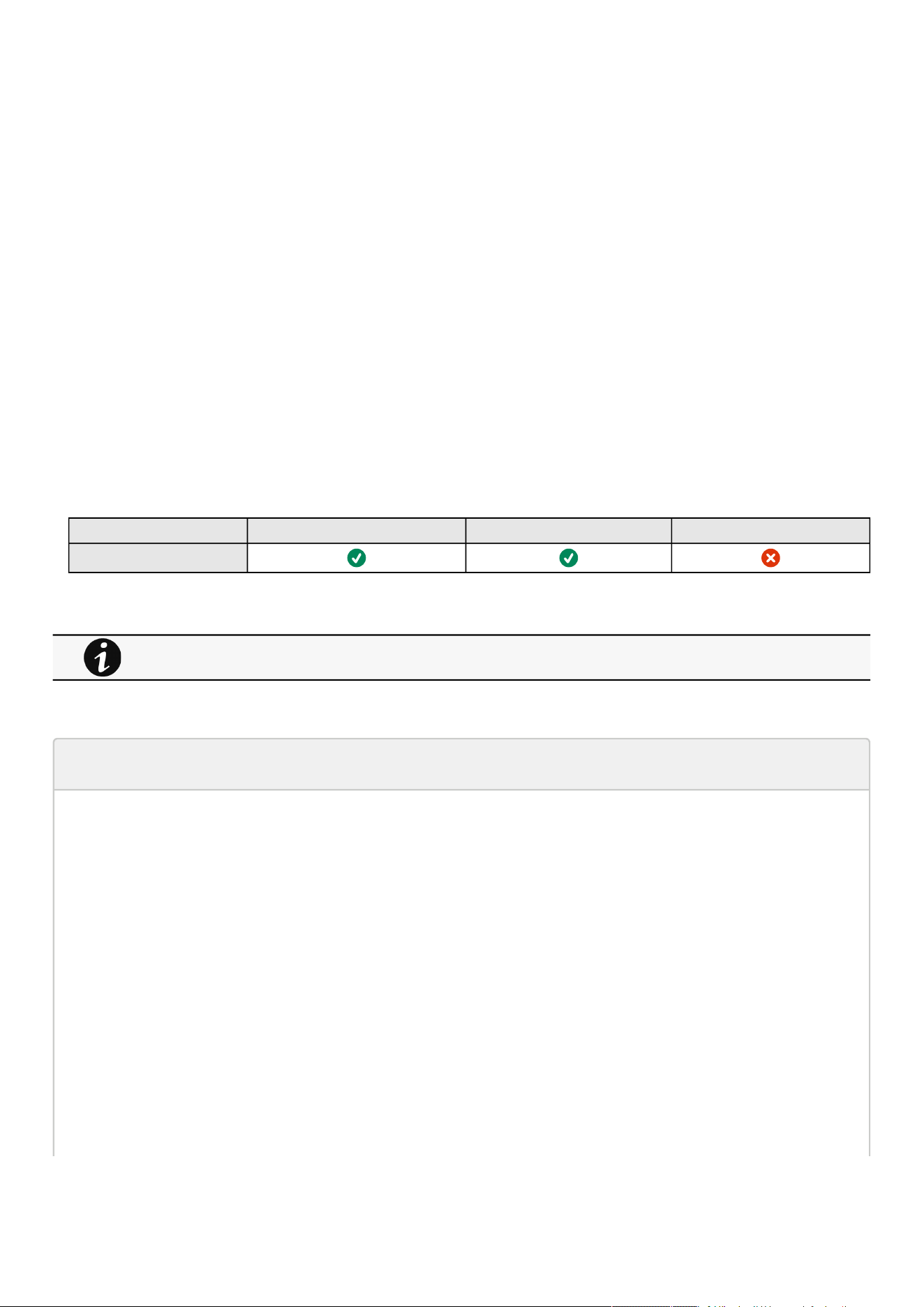
Controls
Contextual help of the web interface – 52
•
•
•
Safe OFF
This will shut off the load connected to the associated load segment. Protected applications are safely powered down.
This control is available only if the status is not OFF and if there are no active commands running.
Safe reboot
This will power down and then switch ON the load connected to the associatedload segment. Protected applications are
safely powered down.
This control is available only if the status is not OFF and if there are no active commands running.
Switch ON
This will switch ON the load connected to the associatedload segment.
This control is available when status is OFFand if there are no active commands running.
3.4.4.2.3 Pending action
Displays the delay before shutdown and delay before startup.
3.4.4.3 Specifics
3.4.4.4 Access rights per profiles
Administrator Operator Viewer
Control
3.4.4.4.1 For other access rights
3.4.4.5 Troubleshooting
Action not allowed in Control/Schedule/Power outage policy
Symptom
Below message is displayed when you access the Control, Schedule or Power outage policy page.
This action is not allowed by the UPS.
To enable it, please refer to the user manual of the UPS and its instructions on how to configure the UPS settings and allow
remote commands.
Possible Cause
1- Remote commands are not allowed due to the UPS configuration (see the action below)
2- The UPS does not support remote commands.
Action
Refer to the UPS user manual and its instruction on how to configure the UPS settings and allow remote commands.
For other access rights, see the Information>>>Access rights per profiles section.

Controls
Contextual help of the web interface – 53
•
•
•
•
•
Example: UPS menu Settings>>>ON/OFF settings>>>Remote command>>>Enable.
3.4.4.5.1 For other issues
3.4.5 Scheduled shutdown
Use Scheduled shutdowns to turn off either the UPS or individual load segments at a specific day and time.
This feature is used for saving energy by turning off equipment outside of office hours or to enhance cybersecurity by powering
down network equipment.
If server shutdown scenarios are defined for any of the connected servers or appliances, they will be triggered before the
corresponding outlets are turned off as configured in shutdown settings.
3.4.5.1 Scheduled shutdown table
The table displays the scheduled shutdowns and includes the following details:
Recurrence–Once/Every day/Every week
Load segment –Primary/Group 1/Group 2
Shutdown time –Date/Time
Restart time –Date/Time
Active –Yes/No
3.4.5.2 Actions
3.4.5.2.1 New
Press the New button to create a scheduled shutdown.
3.4.5.2.2 Delete
Select a schedule shutdown and press the Delete
button to delete the scheduled shutdown.
3.4.5.2.3 Edit
Press the pen iconto editschedule shutdown and to access the settings:
3.4.5.3 Specifics
3.4.5.4 Access rights per profiles
Administrator Operator Viewer
Protection/Scheduled
shutdowns
3.4.5.4.1 For other access rights
For details on other issues, see the Troubleshooting section.
For other access rights, see the Information>>>Access rights per profiles section.
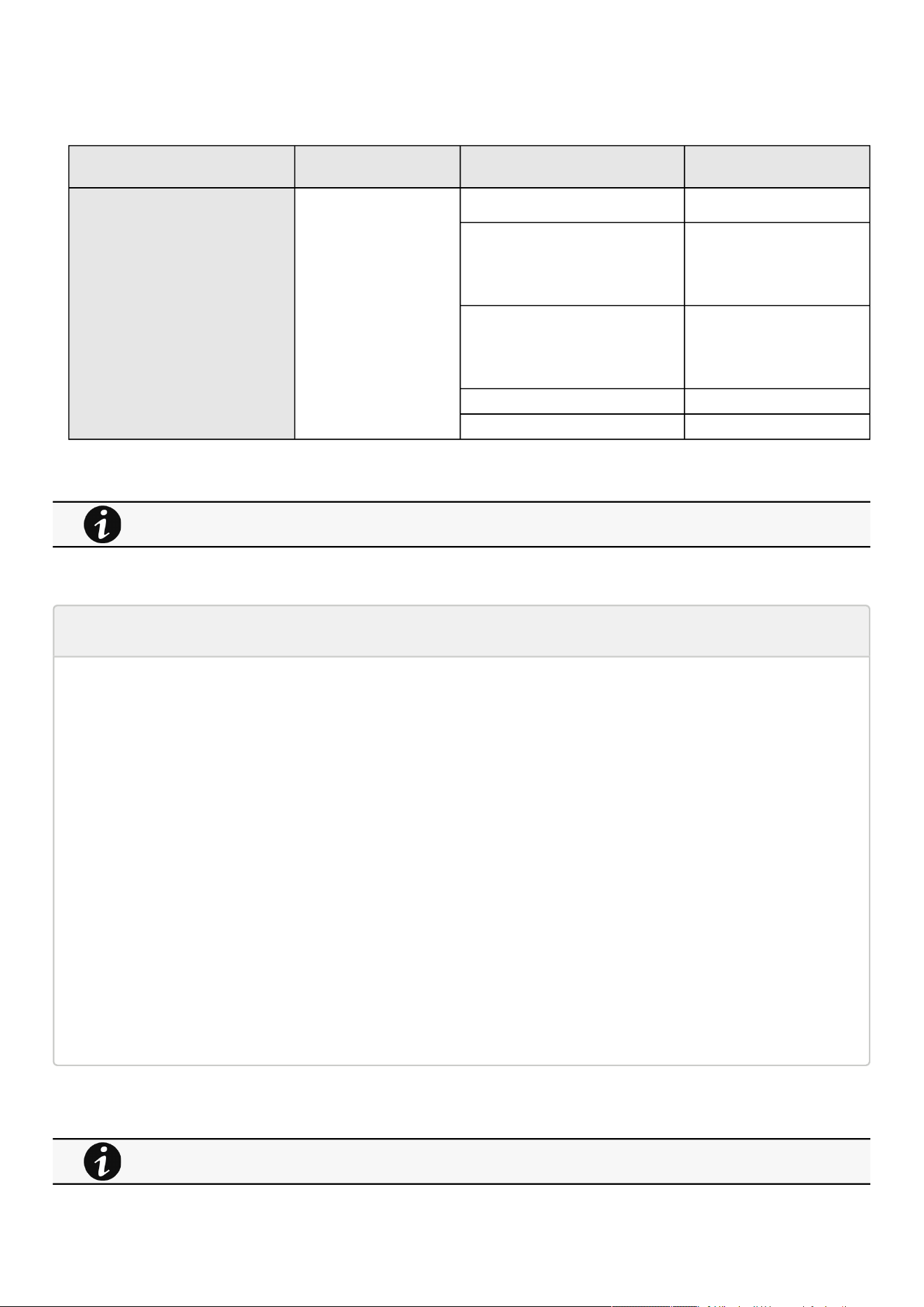
Controls
Contextual help of the web interface – 54
3.4.5.5 Save and Restore
SRR section Settings Possible values
Scheduled shutdown schedule enabled true/false
scheduler 1: Primary
2: Group 1
3: Group 2
recurrence 0: once
1: every day
2: every week
shutdownTimeStamp [timestamp (unix)]
restartTimeStamp [timestamp (unix)]
3.4.5.5.1 Additional information
3.4.5.6 Troubleshooting
Action not allowed in Control/Schedule/Power outage policy
Symptom
Below message is displayed when you access the Control, Schedule or Power outage policy page.
This action is not allowed by the UPS.
To enable it, please refer to the user manual of the UPS and its instructions on how to configure the UPS settings and allow
remote commands.
Possible Cause
1- Remote commands are not allowed due to the UPS configuration (see the action below)
2- The UPS does not support remote commands.
Action
Refer to the UPS user manual and its instruction on how to configure the UPS settings and allow remote commands.
Example: UPS menu Settings>>>ON/OFF settings>>>Remote command>>>Enable.
3.4.5.6.1 For other issues
For details on Save and Restore, see the Save and Restore section.
For details on other issues, see the Troubleshooting section.

Protection
Contextual help of the web interface – 55
•
•
•
•
•
•
•
•
•
•
•
•
•
•
•
•
3.5 Protection
3.5.1 Agents list
3.5.1.1 Pairing with shutdown agents
Authentication and encryption of connections between the UPS network module and shutdown agents is based on matching
certificates. Automated pairing of shutdown agents and UPS network modules is recommended in case the installation is done
manually in a secure and trusted network, and when certificates cannot be created in other ways.
During the selected timeframe, new agent connections to the Network Module are automatically trusted and accepted.
After automatic acceptance, make sure that all listed agents belong to your infrastructure. If not, access may be revoked using the
Delete button.
For maximum security,Eaton recommend followingone of the two methodson the certificate settings page:
Import client certificates manually.
Generate trusted certificate for both clients and Network Module using your own PKI.
3.5.1.1.1 Actions
a Start
Starts the pairing window for the selected timeframe or until it is stopped.
Time countdown is displayed.
b Stop
Stopsthe pairing window.
3.5.1.2 Agents list table
The table displays theIPPagent list that is connected to the Network Moduleand includes the following details:
Name
Address
Version of the Agent
Power source (Powering strategy)
Delay (in seconds)
OS shutdown duration (in seconds)
Status
In service | Protected
In service | Not protected
Stopping | Protected
Stopped | Protected
Communication
Connected | yyyy/mm/dd hh:mm:ss
Lost|yyyy/mm/dd hh:mm:ss
For details on pairing instructions, follow the link pairing instructions in the tile or see the Servicing the Network
Management Module
>>>Pairing agent to the Network Module
section.
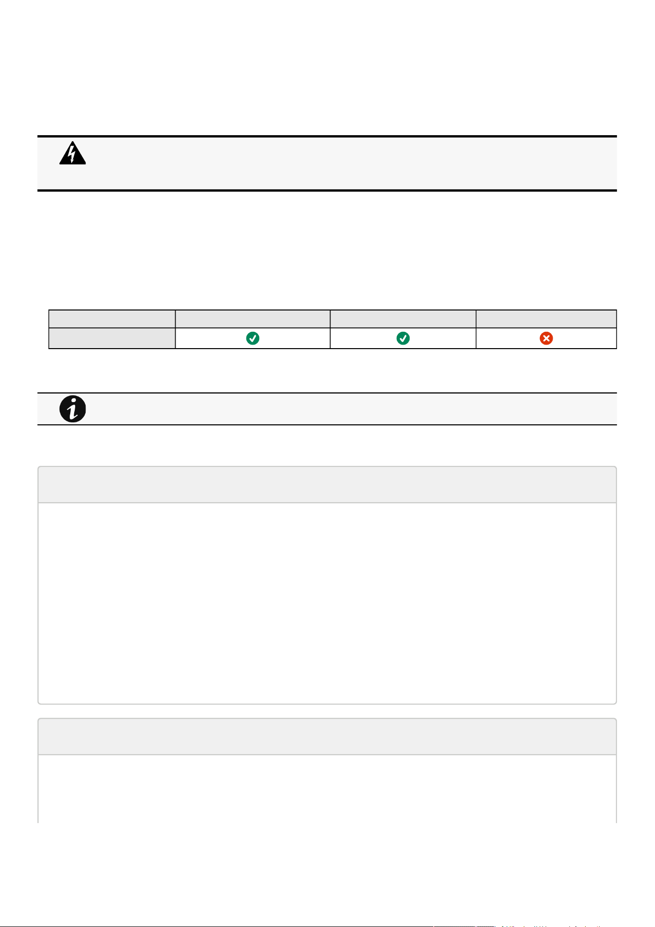
Protection
Contextual help of the web interface – 56
•
3.5.1.3 Actions
3.5.1.3.1 Delete
When communication with the agent is lost, agent can be deleted by using the Delete button.
Select an agent and press the Deletebutton to delete the agent.
3.5.1.4 Specifics
3.5.1.5 Access rights per profiles
Administrator Operator Viewer
Protection/Agent list
3.5.1.5.1 For other access rights
3.5.1.6 Troubleshooting
Card wrong timestamp leads to "Full acquisition has failed" error message on Software
Symptoms:
IPP/IPM shows the error message"The full data acquisition has failed" even if the credentials are correct.
Possible cause:
The Network module timestamp is not correct.
Probably the MQTT certificate is not valid at Network module date.
Action:
Set the right date, time and timezone. If possible, use a NTP server, refer to Contextual
help>>>Settings>>>General>>>System details>>>Time & date settings section.
Software is not able to communicate with the Network module
Symptoms
In the Network Module,in Contextual help>>>Protection>>>Agent list>>>Agent list table , agent is showing "Lost" as
a status.
When the agent is connected, the Delete function will not work correctly because the agent will keep on trying to
re-connect.
So connect to the software, remove the Network module from the Software nodes list (in the nodes list, right click
on the Network module and click remove nodes).
For other access rights, see the Information>>>Access rights per profiles section.

Protection
Contextual help of the web interface – 57
•
•
•
•
•
•
•
•
•
•
•
•
•
•
In the Network Module,in Contextual help>>>Settings>>>Certificate>>>Trusted remote certificates , the status of
theProtected applications (MQTT) is showing"Not valid yet".
IPP/IPM shows "The authentication has failed", "The notifications reception encountered error".
Possible cause
The IPP/IPM certificate is not yet valid for the Network Module.
Certificates of IPP/IPM and the Network Module are not matching so that authentication and encryption of connections
between the Network Module and the shutdown agents is not working.
Setup
IPP/IPM is started.
Network module is connected to the UPS and to the network.
Action #1
Check if the IPP/IPM certificate validity for the Network Module.
STEP 1:Connect to the Network Module
On a network computer, launch a supported web browser. The browser window appears.
In the Address/Location field, enter:https://xxx.xxx.xxx.xxx/where xxx.xxx.xxx.xxx is the static IP address of the
Network Module.
The log in screen appears.
Enter the user name in the User Name field.
Enter the password in the Password field.
ClickLogin. The Network Module web interface appears.
STEP 2:Navigate toSettings/Certificatespage
STEP 3:In theTrusted remote certificatessection, check the status of theProtected applications (MQTT).
If it is "Valid"go to Action#2 STEP 2, if it is "Not yet valid", time of the need to be synchronized with IPP/IPM .
STEP 4:Synchronize the time of the Network Module with IPP/IPM and check that the status of theProtected applications
(MQTT)is now valid.
Communication will then recover, if notgo to Action#2 STEP 2.
Action #2
Pair agent to the Network Module with automatic acceptance (recommended in case the installation is done in a secure and
trusted network).
STEP 1:Connect to the Network Module.
On a network computer, launch a supported web browser. The browser window appears.
In the Address/Location field, enter:https://xxx.xxx.xxx.xxx/where xxx.xxx.xxx.xxx is the static IP address of the
Network Module.
The log in screen appears.
Enter the user name in the User Name field.
Enter the password in the Password field.
ClickLogin. The Network Module web interface appears.
STEP 2:Navigate toProtection/Agents listpage.
STEP 3:In thePairing with shutdown agentssection, select the time to accept new agents and press theStartbutton
andContinue. During the selected timeframe, new agent connections to the Network Module are automatically trusted and
accepted.
STEP 4:Action on the agent( IPP/IPM )while the time to accepts new agents is running on the Network Module
For manual pairing (maximum security), go to Servicing the Network Management Module
>>>Pairing agent
to the Network Module
section and then go to STEP 2, item 1.
Protection
Contextual help of the web interface – 58
•
•
•
•
•
•
Remove theNetwork module certificate file(s) *.0that is (are) located in the folder
Eaton\IntelligentPowerProtector\configs\tls.
Client server is not restarting
Symptom
Utility power has been restored, the UPS and its load segments are powered on, but the Client server does not restart.
Possible Cause
The “Automatic Power ON” server setup setting might be disabled.
Action
In the server system BIOS, change the setting for Automatic Power ON to "Enabled".
3.5.1.6.1 For other issues
3.5.2 Agent shutdown sequencing
3.5.2.1 Agent shutdown sequence timing
All agents that are connected to the Network Module are displayed in tables by power sources.
Primary
Group 1
Group 2
The 'local agent' settingis used for settingfor example a minimum shutdown duration, or a power down delay for a load segment
that has no registered shutdown agents.
One use case would be a load segment that powers network equipment that needs to stay on while servers and storage perform
their orderly shutdown.
The tables include the following details:
Name
Delay (in seconds)
OS shutdown duration (in seconds)
3.5.2.2 Actions
3.5.2.2.1 Set Delay
Select and directly change the setting in the table and then Save.
For details on other issues, see the Troubleshooting section.
•
•
A shutdown time summary is calculated and displayed on the top of the table:
Shutdown time: maximum time (Delay + OS shutdown duration + 10s) calculated among all the agents.
Immediate shutdown time (OS shutdown duration + 10s)calculated among all the agents.
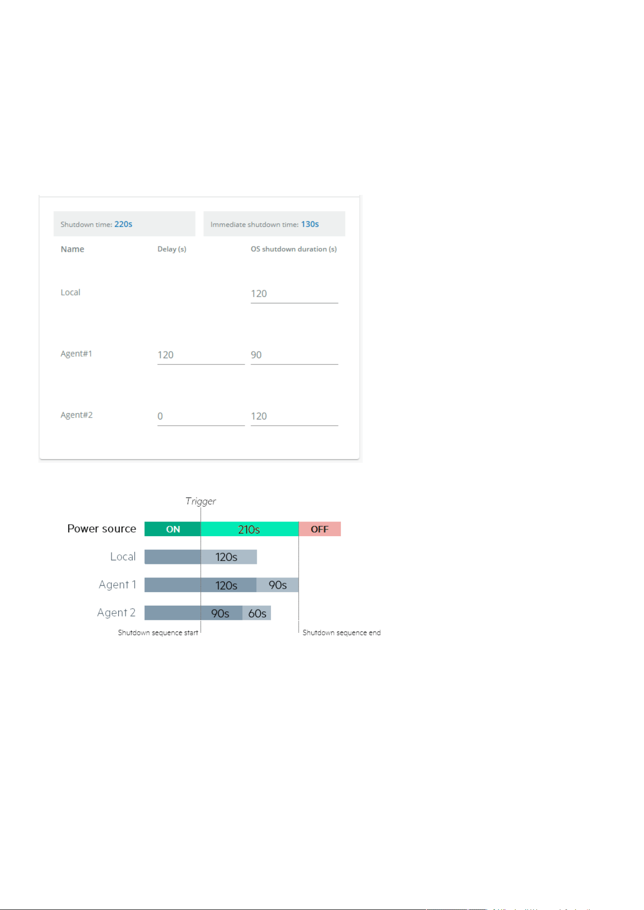
Protection
Contextual help of the web interface – 59
3.5.2.2.2 Set OS shutdown duration
Select and directly change the setting in the tableand thenSave.
3.5.2.3 Examples
Examples below show the impact of agent settings on the shutdown sequence for a shutdown or an immediate shutdown.
3.5.2.3.1 Example #1
→ Shutdown time: 210s + 10s = 220s
→ Immediate shutdown time: 120s + 10s = 130s
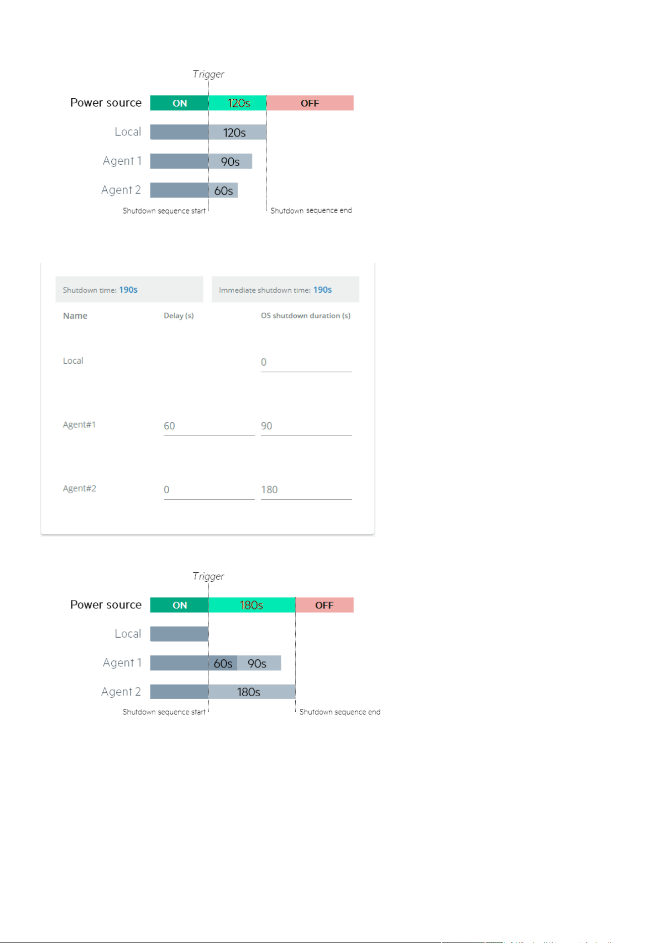
Protection
Contextual help of the web interface – 60
3.5.2.3.2 Example #2
→ Shutdown time: 180s + 10s = 190s
→ Immediate shutdown time: 180s +10s = 190s
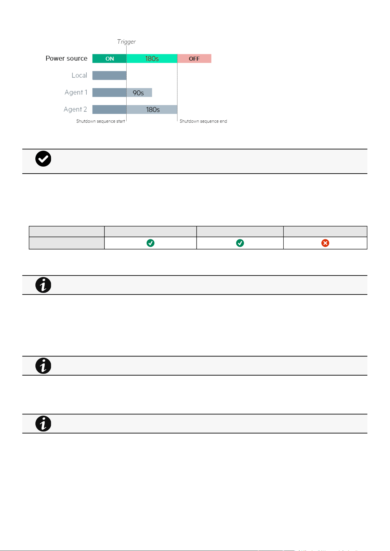
Protection
Contextual help of the web interface – 61
3.5.2.4 Specifics
3.5.2.5 Access rights per profiles
Administrator Operator Viewer
Protection/Agent settings
3.5.2.5.1 For other access rights
3.5.3 Shutdown on power outage
These setting are in conjunction with the shutdown agents andcontrol how the network module directs the shutdown of protected
servers and appliances. It gives the possibility to prioritize and schedule shutdown actions so that the IT system is powered down
in the correct order. For example, applications first, database servers next, and storage last. It is also possible to turn off some
outlets to reduce power consumption and get longer battery runtime for the most important devices.
3.5.3.1 Shutdown on power outage criteria
Shutdown criteria are set per power source (outlet groups) if they are present in the UPS.
3.5.3.1.1 Shutdown criteria selection
The available criteria for shutdown are listed below:
a Maximize availability (default)
To end the shutdown sequence 30s before the end of backup time.
The trigger in the diagram isthe moment whenthe shutdown sequence starts, and it is defined in theContextual
help>>>Protection>>>Scheduled shutdownor theContextual help>>>Protection>>>Shutdown on power
outagesections for each power source.
For other access rights, see the Information>>>Access rights per profiles section.
For examples on Powering down applications see theServicing the Network Management Module>>>Powering
down/up applications examples section.
By default, shutdown criterias are set to Maximize availability.
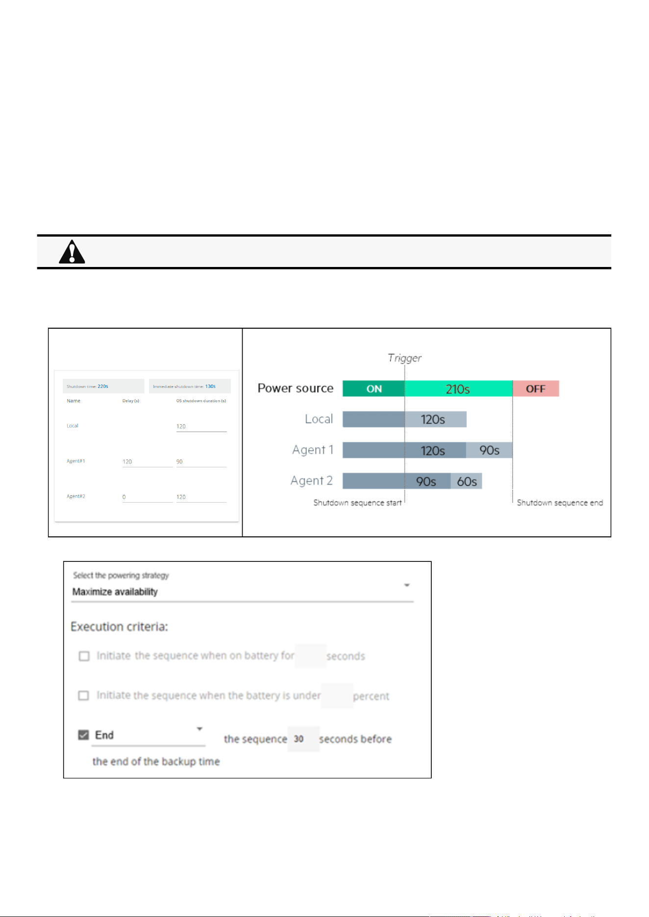
Protection
Contextual help of the web interface – 62
•
•
•
b Immediate OFF
To initiate the shutdown sequence when on battery for 10 seconds.
c Custom
Several conditions can be set to define shutdown criteria:
To initiate the shutdown sequence when on battery for 10 seconds.
To initiate the sequence when the battery reaches the set capacity in (%)
To initiate or end the shutdown sequence after the set time in (s) before the end of backup time.
When there are several conditions to start the shutdown sequence, the shutdown sequence will start as soon as one of the
condition is reached.
d Settings examples
All the following examples are using below agent's settings.
→ Shutdown time: 210s
Example 1: Maximize availability
When primary shuts OFF, both group1 and group 2 shut OFF immediately.
So if Primary is set to Immediate OFF, groups policies should be restricted toImmediate OFF.
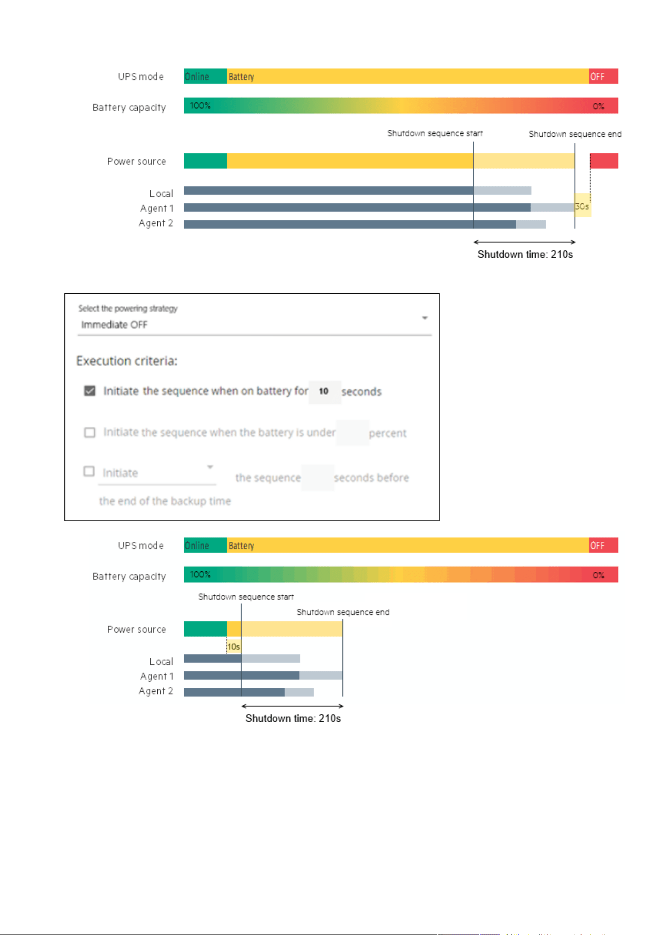
Protection
Contextual help of the web interface – 63
Example 2: Immediate OFF
Example 4: Custom
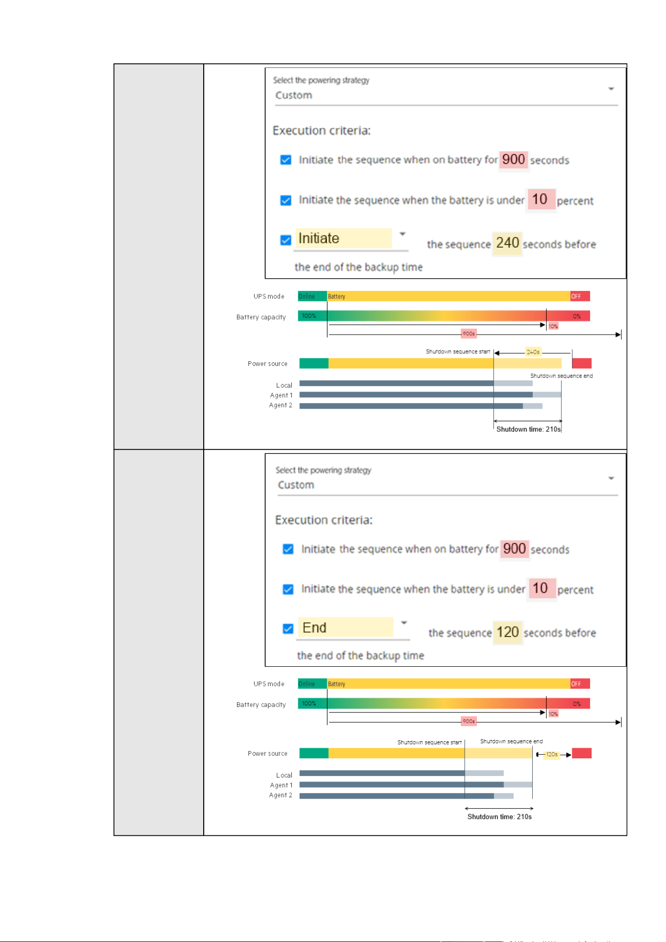
Protection
Contextual help of the web interface – 64
Settings #1
Settings #2
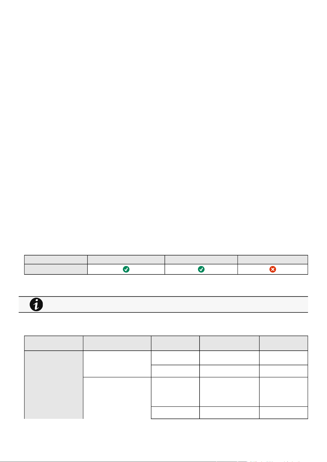
Protection
Contextual help of the web interface – 65
•
•
3.5.3.1.2 On low battery warning
In some cases, like a renewed power failure or failed battery, the capacity is much lower than anticipated. The UPS gives a Low
battery warning when there is 2 - 3 minutes of estimated runtime left, depending on the UPS and its settings. This time is typically
enough for shutting down a server but does not allow sophisticated sequential shutdown schemes.
The Low battery policy is intended for these cases.
3.5.3.1.3 When utility comes back
Note: When utility comes back settings cannot be altered for three phase UPS units and will remain at their defaults.
These settings define the restart sequence when utility comes back. For example, thisallows sequential startup of the IT system
so that network and storage devices are connected to 'Primary' and start up immediately. After a delay database servers in Group1
are powered up, and then application and web servers in Group 2 are powered up. This startup would ensure that necessary
services would be available for each layer when needed. A sequential startup will also help avoid a peak power draw in the
beginning.
a Options
Keep shutdown sequence running until the end, and then restart (forced reboot).
Wait until UPS battery capacity exceeds a set percentage value in (%), and then automatically restart the UPS.
Then restartGroup 1 after a set time in (s).
Then restart Group 2 after a set time in (s).
b Enable/Disable
Each option listed above can be enabled or disabled with check-boxes.
When disabled, the option will be greyed out.
3.5.3.2 Specifics
3.5.3.3 Access rights per profiles
Administrator Operator Viewer
Protection/Sequence
3.5.3.3.1 For other access rights
3.5.3.4 Save and Restore
SRR section SRR sub section Settings Possible values
Shutdown on power outage powerOutagePolicy/Settings panicShutdownTrigger
s
onLowStateOfCharge true/false
restart enabled true/false
powerOutagePolicy/
suppliersSettings
id 1: Primary
2: Group 1
3: Group 2
settings localShutdownDuration [time in seconds]
For other access rights, see the Information>>>Access rights per profiles section.

Protection
Contextual help of the web interface – 66
shutdownTriggers/
powerOutage
enabled true/false
capacityLessThan [percentage]
afterBackupTime [time in seconds]
startShutdownBeforeEndOf
Backup
[time in seconds]
endShutdownBeforeEndOfB
ackup
[time in seconds]
3.5.3.4.1 Additional information
3.5.3.5 Troubleshooting
Action not allowed in Control/Schedule/Power outage policy
Symptom
Below message is displayed when you access the Control, Schedule or Power outage policy page.
This action is not allowed by the UPS.
To enable it, please refer to the user manual of the UPS and its instructions on how to configure the UPS settings and allow
remote commands.
Possible Cause
1- Remote commands are not allowed due to the UPS configuration (see the action below)
2- The UPS does not support remote commands.
Action
Refer to the UPS user manual and its instruction on how to configure the UPS settings and allow remote commands.
Example: UPS menu Settings>>>ON/OFF settings>>>Remote command>>>Enable.
Client server is not restarting
Symptom
Utility power has been restored, the UPS and its load segments are powered on, but the Client server does not restart.
Possible Cause
The “Automatic Power ON” server setup setting might be disabled.
For details on Save and Restore, see the Save and Restore section.

Environment
Contextual help of the web interface – 67
•
•
•
•
•
•
•
•
•
•
•
•
•
Action
In the server system BIOS, change the setting for Automatic Power ON to "Enabled".
3.5.3.5.1 For other issues
3.6 Environment
3.6.1 Commissioning/Status
3.6.1.1 Sensors commissioning/Status table
The table displays the sensors commissioning information and includes the following details.
Name
Location –location-position-elevation
Temperature
Humidity
Dry contact #1 –Status and name
Dry contact #2 –Status and name
Communication –Connected/Lost with dates
3.6.1.2 Actions
3.6.1.2.1 Download sensors measures
Press theDownload sensors measuresbuttonto download the sensors log file:
If available, possible measures are listed below:
Temperature of <sensor_1> (in K, 1 decimal digit)
Humidity of <sensor_1> (in %, 1 decimal digit)
Temperature of <sensor_2>> (in K, 1 decimal digit)
Humidity of <sensor_2>(in %, 1 decimal digit)
Temperature of <sensor_3>(in K, 1 decimal digit)
Humidity of <sensor_3>(in %RH, 1 decimal digit)
3.6.1.2.2 Discover
At first the table is empty, press theDiscoverbutton to launch the sensor discovery process.
If sensors are discovered, the table is populated accordingly
3.6.1.2.3 Delete
Select a sensor and press theDeletebutton to delete the sensor.
For details on other issues, see the Troubleshooting section.
°C = K - 273.15
°F = K x 9/5 -459.67
When a sensor is deleted, all the commissioning information are deleted.
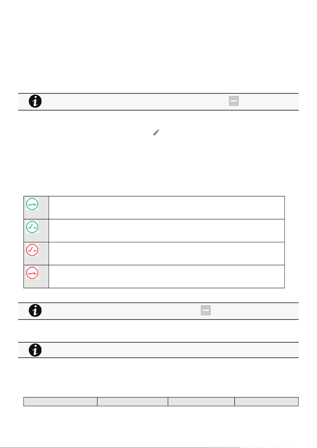
Environment
Contextual help of the web interface – 68
•
•
•
•
•
•
•
3.6.1.2.4 Define offsets
1.Select the sensors.
2. Press theDefine offsetbutton to adjust the temperature and humidity offsets of the selected sensors.
3. Extend the temperature or humidity section.
4. Set the offsets in the cell, temperatures and humidity will be updated accordingly.
5. Press theSavebutton when done.
3.6.1.2.5 Edit
Press the pen logoto edit sensor communication information:
You will get access to the following information and settings:
Product reference
Part number
Serial number
Name
Location
Temperature and humidity – Active (Yes, No)
Dry contacts –Active (Yes, No)/Name/Polarity (Normally open, Normally closed)
The dry contact is close and this is normal because it is configured as normally close.
The dry contact is open and this is normal because it is configured as normally open.
The dry contact is open and this is not normal because it is configured as normally close.
The dry contact is close and this is not normal because it is configured as normally open.
PressSaveafter modifications.
3.6.1.3 Note:
3.6.1.4 Specifics
3.6.1.5 Access rights per profiles
Administrator Operator Viewer
Deactivated humidity or temperatures are not displayed and replaced by this icon:
Deactivated dry contacts are not displayed and replaced by this icon:
If the UPS provides temperature compensated battery charging option, see theServicing the EMP>>>Using the
EMP for temperature compensated battery charging
section.

Environment
Contextual help of the web interface – 69
Environment/Commissioning
Environment/Status
3.6.1.5.1 For other access rights
3.6.1.6 Troubleshooting
EMP detection fails at discovery stage
In the Network Module,in Contextual help>>>Environment>>>Commissioning/Status , EMPs are missing in the Sensor
commissioning table.
Symptom #1
The EMPs green RJ45 LED (FROM DEVICE) is not ON.
Possible causes
The EMPs are not powered by the Network module.
Action #1-1
Launch again the discovery, if it is still not ok, go to Action #1-2.
Action #1-2
1- Check the EMPs connection and cables.
Refer to the sections Servicing the EMP>>>Installing the EMP>>>Cabling the first EMP to the device and Servicing the
EMP>>>Installing the EMP>>>Daisy chaining 3 EMPs .
2- Disconnect and reconnect the USB to RS485 cable.
3-Launch the discovery, if it is still not ok, go to Action #1-3.
Action #1-3
1- Reboot the Network module.
2-Launch the discovery.
Symptom #2
The EMPs orange RJ45 LEDs are not blinking.
Possible causes
C#1: the EMP address switches are all set to 0.
C#2: the EMPs are daisy chained, the Modbus address is the same on the missing EMPs.
Action #2-1
1- Change the address of the EMPs to have different address and avoid all switches to 0.
For other access rights, see the Information>>>Access rights per profiles section.

Environment
Contextual help of the web interface – 70
•
•
•
•
•
•
•
•
•
•
Refer to the section Servicing the EMP>>>Defining EMPs address and termination>>>Manual addressing .
2- Disconnect and reconnect the USB to RS485 cable. The address change is only taken into account after an EMP power-up.
3-Launch the discovery,if it is still not ok, go to Action #2-2.
Action #2-2
1- Reboot the Network module.
Refer to the section Contextual help>>>Maintenance>>>Services>>>Reboot .
2-Launch the discovery.
3.6.1.6.1 For other issues
3.6.2 Alarm configuration
3.6.2.1 Temperature
The table shows the following information and settings for each sensor:
Name
Location
Enabled– yes/no
Low critical threshold– xx°C or xx°F
Low warning threshold– xx°C or xx°F
High warning threshold– xx°C or xx°F
High critical threshold– xx°C or xx°F
Hysteresis– x°C or x°F
Visual update
Live reading (MIN-MAX shows the minimal and maximal temperature measured by the sensor)
3.6.2.1.1 Actions
a Set Enabled
Select and directly change the setting in the tableand thenSave.
When disabled, no alarm will be sent.
b Set alarm threshold
Enable the alarm first and then change the setting in the tableand thenSave.
When a warning threshold is reached, an alarm will be sent with a warning level.
When a critical threshold is reached, an alarm will be sent with a critical level.
For details on other issues, see the Troubleshooting section.
•
•
•
Humidity, temperatures or dry contacts deactivated during commissioning are not displayed.
Gauge color code:
Green: Value inside thresholds.
Orange/Red: Value outside thresholds.
Grey: No thresholds provided by the device.

Environment
Contextual help of the web interface – 71
•
•
•
•
•
•
•
•
•
•
•
•
•
•
c Set Hysteresis
Enable the alarm first and change the setting in the tableand thenSave.
The hysteresis is the difference between the value where the alarm turns ON from turning OFF and the value where it turns OFF
from turning ON.
3.6.2.2 Humidity
The table shows the following information and settings for each sensor:
Name
Location
Enabled–yes/no
Low critical threshold– xx%
Low warning threshold– xx%
High warning threshold– xx%
High critical threshold– xx%
Hysteresis– x%
Visual update
Live reading (MIN-MAX shows the minimal and maximal humidity measured by the sensor)
3.6.2.2.1 Actions
a Set Enabled
Select and directly change the setting in the tableand thenSave.
When disabled, no alarm will be sent.
b Set alarm threshold
Enable the alarm first and then change the setting in the tableand thenSave.
When a warning threshold is reached, an alarm will be sent with a warning level.
When a critical threshold is reached, an alarm will be sent with a critical level.
c Set Hysteresis
Enable the alarm first and then change the setting in the tableand thenSave.
The hysteresis is the difference between the value where the alarm turns ON from turning OFF and the value where it turns OFF
from turning ON.
3.6.2.3 Dry contacts
The table shows the following settings for each dry contact:
Name
Location
Enabled–yes/no
Alarm severity – Info/Warning/Critical
3.6.2.3.1 Actions
a Set Enabled
Enable the alarm first and thenchangethe setting in the tableand thenSave.
When disabled, no alarm will be sent.
b Set alarm severity
Enable the alarm first and thenchangethe setting in the tableand thenSave.
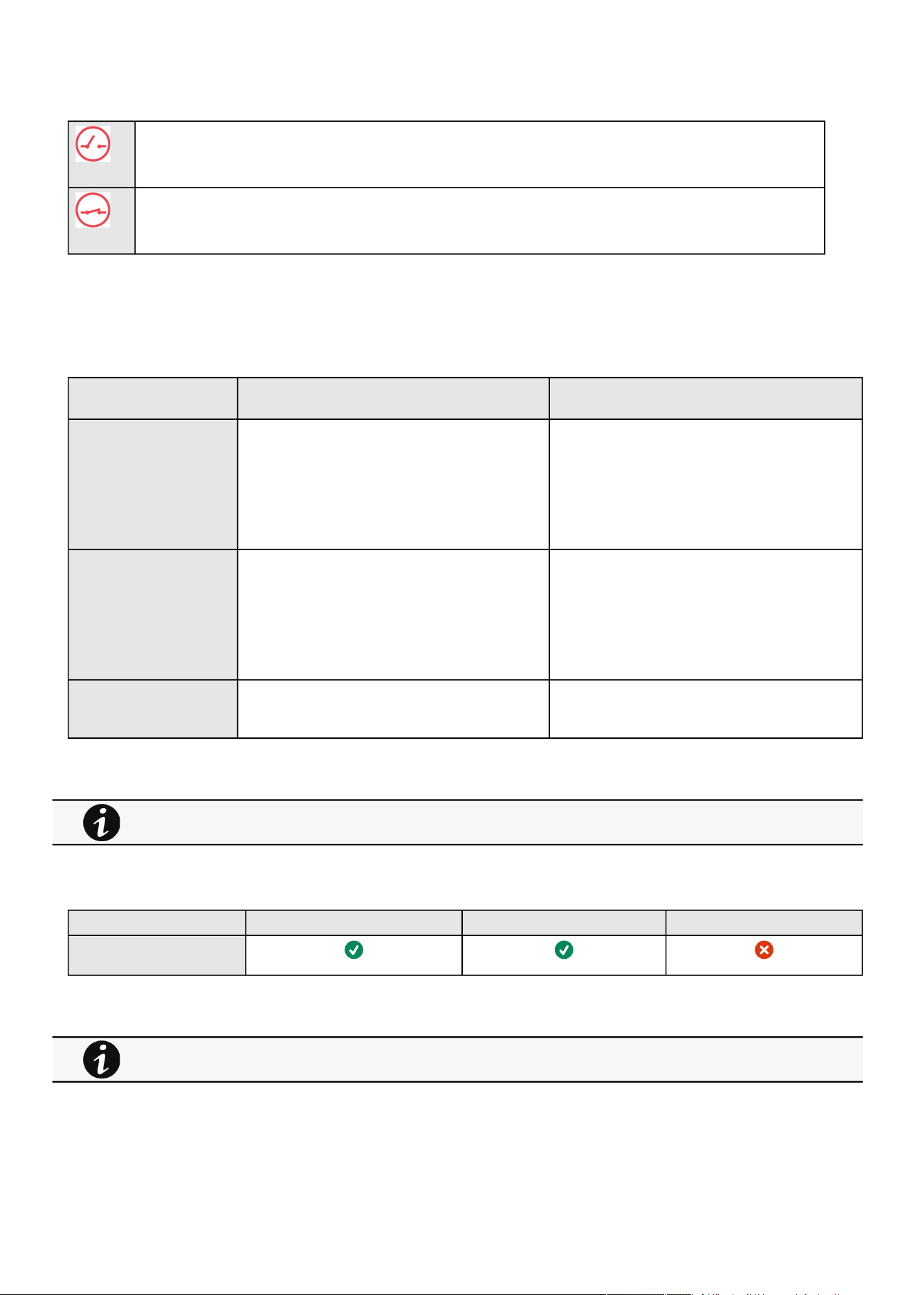
Environment
Contextual help of the web interface – 72
When the dry contacts is not in a normal position, an alarm will be sent at the selected level.
The dry contact is open and this is not normal because it is configured as normally close.
The dry contact is close and this is not normal because it is configured as normally open.
3.6.2.4 Specifics
3.6.2.5 Default settings and possible parameters - Environment Alarm configuration
Default setting Possible parameters
Temperature Enabled—No
Low critical – 0°C/32°F
Low warning – 10°C/50°F
High warning – 70°C/158°F
High critical – 80°C/176°F
Enabled—No/Yes
low critical<low warning<high warning<high critical
Humidity Enabled—No
Low critical – 10%
Low warning – 20%
High warning – 80%
High critical – 90%
Enabled—No/Yes
0%<low critical<low warning<high warning<high
critical<100%
Dry contacts Enabled—No
Alarm severity – Warning
Enabled—No/Yes
Alarm severity – Info/Warning/Critical
3.6.2.5.1 For other settings
3.6.2.6 Access rights per profiles
Administrator Operator Viewer
Environment/Alarm
configuration
3.6.2.6.1 For other access rights
3.6.3 Information
Sensor information is an overviewof all the sensors information connected to the Network Module.
For other settings, see the Information>>>Default settings parameters section.
For other access rights, see the Information>>>Access rights per profiles section.

Settings
Contextual help of the web interface – 73
•
•
•
•
•
•
•
Physical name
Vendor
Part number
Firmware version
UUID
Serial number
Location
3.6.3.1 Specifics
3.6.3.2 Access rights per profiles
Administrator Operator Viewer
Environment/Information
3.6.3.2.1 For other access rights
3.7 Settings
3.7.1 General
3.7.1.1 System details
3.7.1.1.1 Location
Text field that is used to provide the card location information.
Card system information is updated to show the defined location.
3.7.1.1.2 Contact
Text field that is used to provide the contact name information.
Card system information is updated to show the contact name.
3.7.1.1.3 System name
Text field that is used to provide the system name information.
Card system information is updated to show the system name.
3.7.1.2 Date & Time
The current date and time appearsat the top of the screen.
You can set the time either manually or automatically.
3.7.1.2.1 Manual mode:Manually entering the date and time
1.Select the time zone for your geographic area.
2. Select the date and time.
3. Save the changes.
For other access rights, see the Information>>>Access rights per profiles section.

Settings
Contextual help of the web interface – 74
•
•
•
•
•
•
•
•
•
3.7.1.2.2 Dynamic (NTP):Synchronizing the date and time with an NTP server
1. Select the time zone for your geographic area.
2.Enter the IP address or host name of the NTP servers in theNTP server fields (up to 5 servers).
3. Save the changes.
3.7.1.2.3 Dynamic (NTP):Synchronizing the date and time from the DHCP server
1. Select the time zone for your geographic area.
2.Select Get NTP server from DHCP
3. Save the changes.
3.7.1.3 Email notification settings
3.7.1.3.1 Email sending configuration table
The table shows all the email sending configuration and includes the following details:
Configuration name
Email address
Notification updates –Displays Events notification/Periodic report icons when active.
Status– Active/Inactive/In delegation
3.7.1.3.2 Actions
a Add
Press theNewbutton to create a new email sending configuration.
b Remove
Select an email sending configuration and press theDeletebutton to remove it.
c Edit
Press the pen iconto edit email sending configuration:
You will get access to the following settings:
Custom name
Email address
Status– Active/Inactive
Hide the IP address from the email body– Disabled/Enabled
This setting will be forced to Enabled if Enabled in the SMTP settings.
Schedule report–Active/Recurrence/Starting/Topic selection– Card/Devices
DST is managed based on the time zone.
For examples on email sending configuration see theServicing the Network Management Module>>>Subscribing
to a set of alarms for email notification section.
Attachment will contains only logs that have occurred during the recurrence.

Settings
Contextual help of the web interface – 75
•
•
•
•
•
•
•
•
•
Alarm notifications– Severity level/Attach logs/Exceptions on events notification
3.7.1.4 SMTP settings
SMTP is an internet standard for electronic email transmission.
The following SMTP settings are configurable:
Server IP/Hostname – Enter the host name or IP address of the SMTP server used to transfer email messages in the SMTP
Server field.
Port
Default sender address
Hide the IP address from the email body–Disabled/Enabled
If Enabled, it will force this setting to Enabled in the Email notification settings.
Secure SMTP connection–Verify certificate authority
SMTP server authentication– Username/Password
Select the SMTP server authentication checkbox to require a user name and a password for SNMP authentication, enter the
Username and the Password.
Save and test server configuration
3.7.1.5 Specifics
3.7.1.6 Default settings and possible parameters - General
Default setting Possible parameters
System details Location—empty
Contact—empty
System name—empty
Time & date settings—Manual (Time zone: Europe/
Paris)
Location — 31 characters maximum
Contact— 255 characters maximum
System name— 255 characters maximum
Time & date settings—Manual (Time zone: selection on
map/Date) / Dynamic (NTP)
Email notification settings No email 5 configurations maximum
Custom name — 128 characters maximum
Email address — 128 characters maximum
Hide IP address from the email body — enable/disabled
Status — Active/Inactive
Alarm notifications
Active — No/Yes
All card events – Subscribe/Attach logs
Critical alarm – Subscribe/Attach logs
Warning alarm – Subscribe/Attach logs
Info alarm – Subscribe/Attach logs
All device events – Subscribe/Attach
measures/Attach logs
Critical alarm – Subscribe/Attach measures/
Attach logs
Warning alarm – Subscribe/Attach measures/
Attach logs
Info alarm – Subscribe/Attach measures/
Attach logs
Always notify events with code
Never notify events with code
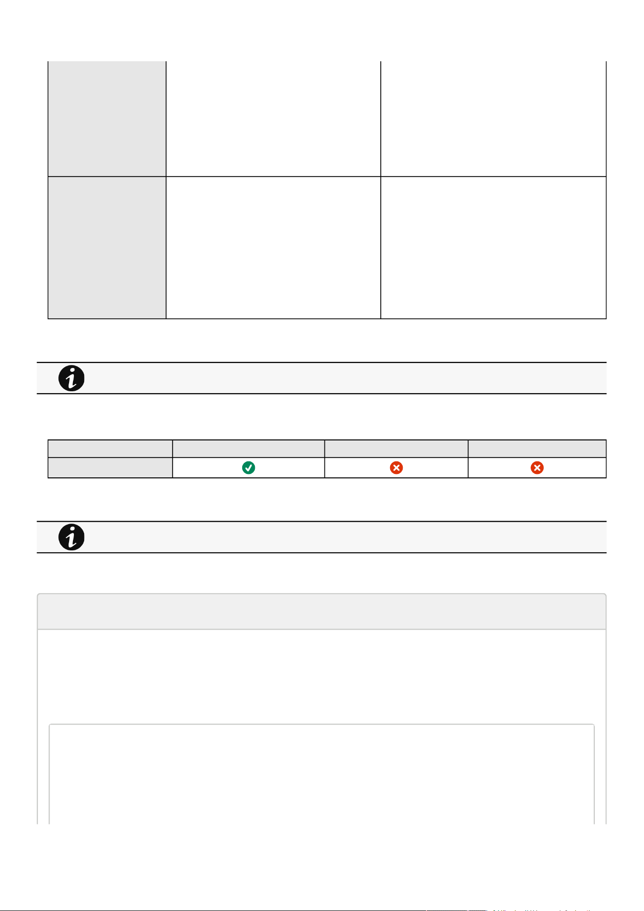
Settings
Contextual help of the web interface – 76
• Schedule report
Active — No/Yes
Recurrence – Every day/Every week/Every
month
Starting – Date and time
Card events – Subscribe/Attach logs
Device events – Subscribe/Attach measures/
Attach logs
SMTP settings Server IP/Hostname — blank
SMTP server authentication — disabled
Port — 25
Default sender address —
device
@networkcard.com
Hide IP address from the email body — disabled
Secure SMTP connection — enabled
Verify certificate authority — disabled
SMTP server authentication — disabled
Server IP/Hostname — 128 characters maximum
SMTP server authentication — disable/enable
(Username/Password — 128 characters maximum)
Port — x-xxx
Sender address — 128 characters maximum
Hide IP address from the email body — enable/disabled
Secure SMTP connection — enable/disable
Verify certificate authority — disable/enable
3.7.1.6.1 For other settings
3.7.1.7 Access rights per profiles
Administrator Operator Viewer
General
3.7.1.7.1 For other access rights
3.7.1.8 CLI commands
email-test
Description
mail-test sends test email to troubleshoot SMTP issues.
Help
Usage: email-test <command> ...
Test SMTP configuration.
Commands:
email-test -h, --help, Display help page
email-test -r, --recipient <recipient_address>
For other settings, see the Information>>>Default settings parameters section.
For other access rights, see the Information>>>Access rights per profiles section.

Settings
Contextual help of the web interface – 77
Send test email to the
<recipient_address> Email address of the recipient
time
Description
Command used to displayor changetime and date.
Help
For Viewer and Operator profiles:
time -h
Usage: time [OPTION]...
Display time and date.
-h, --help display help page
-p, --print display date and time in YYYYMMDDhhmmss format
For Administrator profile:
time -h
Usage:time[OPTION]...
Display time and date, change time and date.
-h,--helpdisplayhelppage
-p,--printdisplaydateandtimeinYYYYMMDDhhmmssformat
-s,--set<mode>
Modevalues:
-setdateandtime(formatYYYYMMDDhhmmss)
manual<dateandtime>
-setpreferredandalternateNTPservers
ntpmanual<preferredserver><alternateserver>
-automaticallysetdateandtime
ntpauto
Examples of usage:
-> Set date 2017-11-08 and time 22:00
time--setmanual201711082200
-> Set preferred and alternate NTP servers
time--setntpmanualfr.pool.ntp.orgde.pool.ntp.org
Examples of usage
-> Set date 2017-11-08 and time 22:00
time --set manual 201711082200

Settings
Contextual help of the web interface – 78
-> Set preferred and alternate NTP servers
time --set ntpmanual fr.pool.ntp.org de.pool.ntp.org
3.7.1.8.1 For other CLI commands
3.7.1.9 Save and Restore
SRR section SRR sub section Settings Sub Setttings Possible values
System details card identification name String: refer to default
settings and possible
parameters for constraints.
contact String: refer to default
settings and possible
parameters for constraints.
location String: refer to default
settings and possible
parameters for constraints.
Time and Date settings date ntp enabled true/false
getServersFromDhcp true/false
servers preferredServer *
alternateServer *
timeZone Examples:
Europe/Paris
Africa/Johannesburg
America/New_York
Asia/Shanghai
Email email notifyOnEvents enabled true/false
cardEvents critical
subscribe
attachEventsLog
true/false
true/false
warning
subscribe
attachEventsLog
true/false
true/false
info
subscribe
attachEventsLog
true/false
true/false
See the CLI commands in the Information>>>CLI section.

Settings
Contextual help of the web interface – 79
devicesEvents critical
subscribe
attachEventsLog
attachMeasuresLog
warning
subscribe
attachEventsLog
attachMeasuresLog
info
subscribe
attachEventsLog
attachMeasuresLog
true/false
true/false
true/false
true/false
true/false
true/false
true/false
true/false
true/false
exceptions notifiedEvents
noneNotifiedEvents
evenst codes separated by
coma
evenst codes separated by
coma
periodicReport enabled
periodicity
startTime
true/false
Every day/week/month
Unix timestamp
card subscribe
attachEventsLog
true/false
true/false
devices subscribe
attachEventsLog
attachMeasuresLog
true/false
true/false
true/false
message sender String: refer to default
settings and possible
parameters for constraints.
subject String: refer to default
settings and possible
parameters for constraints.
hideIpAddress true/false
SMTP smtp certificateData ca Certificate Authority of
SMTP server
port Number: refer to default
settings and possible
parameters for constraints.
enabled true/false
server IP address or hostname of
SMTP server
requireAuth true/false
user Username for server
authentication
password plaintext
cyphered
String: refer to default
settings and possible
parameters for constraints.
-

Settings
Contextual help of the web interface – 80
•
•
•
•
•
•
•
•
•
•
•
•
•
•
fromAddress email address format
ssl 1: None
2: STARTTLS
3: SSL
verifyTlsCert true/false
3.7.1.9.1 Additional information
3.7.2 Local users
3.7.2.1 Local users table
The table shows all the supported local user accounts and includes the following details:
Username
Email
Profile
Status –Status could take following values– Inactive/Locked/Password expired/Active
3.7.2.1.1 Actions
a Add
Press theNew button to add new local users.
b Remove
Select a user and press theDeletebutton to remove it.
c Edit
Press the pen logoto edit user information:
You will get access to the following settings:
Active
Profile
Username
Full name
Email
Phone
Organization– Notify by email about account modification/Password
Reset password
Generate randomly
Enter manually
For details on Save and Restore, see the Save and Restore section.
For the list of access rights per profile refer to the section Full documentation>>>Information>>>Access rights per
profiles.
You can add up to 20 local users. Kindly note that above 10 users connected simultaneously, it is likely to consume
a lot of CPU resources resulting in slower card performance.
Settings
Contextual help of the web interface – 81
•
•
•
•
•
•
•
•
•
•
•
•
Force password to be changed on next login
d Global settings
PressSaveafter modifications.
Password settings
To set the password strength rules, apply the following restrictions:
Minimum length
Minimum upper case
Minimum lower case
Minimum digit
Special character
Password expiration
To set the password expiration rules, apply the following restrictions:
Number of days until password expires
Main administrator password never expire
Lock account
Lock account after a number of invalid tries
Main administrator account will never block
Account timeout
To set the session expiration rules,apply the following restrictions:
No activity timeout (in minutes).
If there is no activity, session expires after the specified amount of time.
Session lease time (in minutes).
If there is activity, session still expires afterthe specified amount of time.
3.7.2.2 Specifics
3.7.2.3 Default settings and possible parameters - Global user settings and Local
users
Default setting Possible parameters
Password settings Minimum length — enabled (8)
Minimum upper case — enabled (1)
Minimum lower case — enabled (1)
Minimum digit — enabled (1)
Special character — enabled (1)
Minimum length — enable (6-32)/disable
Minimum upper case — enable (0-32)/disable
Minimum lower case — enable (0-32)/disable
Minimum digit — enable (0-32)/disable
Special character — enable (0-32)/disable
1.
2.
Main administrator password never expires
If this feature is disabled, the administrator account can be locked after the password expiration.
If Enabled, the administrator password never expires, make sure it is changed regularly.
1.
2.
Main administrator account will never block
If this feature is disabled, the administrator account can be locked after the number of failed connections
defined.
If Enabled, the security level of the administrator account is reduced because unlimited password entry
attempts are allowed.
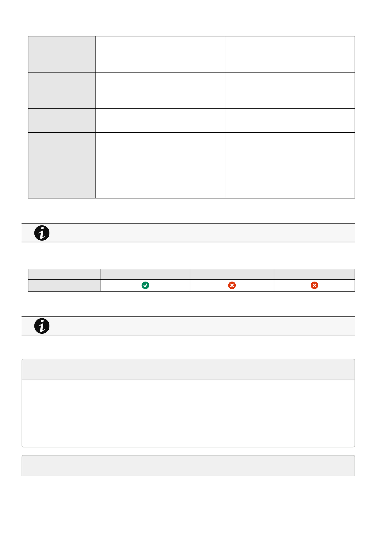
Settings
Contextual help of the web interface – 82
•
•
•
•
•
•
•
•
•
•
•
•
•
•
•
•
•
Password expiration Number of days until password expires — disabled
Main administrator password never expires — disabled
Number of days until password expires — disable/
enable (1-99999)
Main administrator password never expires — disable/
enable
Lock account Lock account after xx invalid tries — disabled
Main administrator account never blocks — disabled
Lock account after xx invalid tries — disable/enable
(1-99)
Main administrator account never blocks — disable/
enable
Account timeout No activity timeout — 60 minutes
Session lease time — 120 minutes
No activity timeout — 1-60 minutes
Session lease time — 60-720 minutes
Local users 1 user only:
Active—Yes
Profile—Administrator
Username—admin
Full Name—blank
Email—blank
Phone—blank
Organization—blank
20 users maximum:
Active—Yes/No
Profile—Administrator/Operator/Viewer
Username—255 characters maximum
Full Name—128 characters maximum
Email—128 characters maximum
Phone—64 characters maximum
Organization—128 characters maximum
3.7.2.3.1 For other settings
3.7.2.4 Access rights per profiles
Administrator Operator Viewer
Local users
3.7.2.4.1 For other access rights
3.7.2.5 CLI commands
whoami
Description
whoami displays current user information:
Username
Profile
Realm
logout
For other settings, see the Information>>>Default settings parameters section.
For other access rights, see the Information>>>Access rights per profiles section.
Settings
Contextual help of the web interface – 83
•
•
Description
Logout the current user.
Help
logout
<cr> logout the user
3.7.2.5.1 For other CLI commands
3.7.2.6 Troubleshooting
How do I log in if I forgot my password?
Action
Askyour administrator for password initialization.
If you are the mainadministrator, yourpasswordcan be reset manually by following steps described in the Servicing
the Network Management Module>>>Recovering main administrator password .
3.7.2.6.1 For other issues
3.7.2.7 Save and Restore
SRR section SRR sub section Settings Possible values
Password settings accountService passwordRules strength
minLengthminUpperCase
minLowerCase
minDigit
minSpecialCharacter
Numbers: refer to default
settings an possible parameters
for constraints.
See the CLI commands in the Information>>>CLI section.
For details on other issues, see the Troubleshooting section.

Settings
Contextual help of the web interface – 84
•
•
•
•
•
•
Password expiration expiration
expiration enabled
afterDays
defaultAccountNeverExpires
true/false
Number: refer to default settings
an possible parameters for
constraints.
true/false
Lock account lockoutRules lockoutRules
enabled
threshold
defaultAccountNeverBlocks
true/false
Number: refer to default settings
an possible parameters for
constraints.
true
Account timeout sessionsService sessionTimeout
sessionLeaseTime
Numbers: refer to default
settings an possible parameters
for constraints.
Local users PredefinedAccounts credentials
enabled
username
passwordExpired
locked
profile
password
plaintext
cyphered
true/false
String: refer to default settings
an possible parameters for
constraints.
true/false
true/false
administrators/operators/viewers
String: refer to default settings
an possible parameters for
constraints.
-
3.7.2.7.1 Additional information
3.7.3 Remote users
3.7.3.1 LDAP
The table shows all the supported severs and includes the following details:
Name
Address
Port
Security
Certificate
Status–Status could take following values– Unreachable/Active
For details on Save and Restore, see the Save and Restore section.

Settings
Contextual help of the web interface – 85
•
•
•
•
•
•
•
•
•
•
•
•
•
•
•
•
•
•
•
•
•
3.7.3.1.1 Actions
a Configure
1.Enable LDAP to be able to configure settings
2. Press Configureto access the following LDAP settings:
Connectivity
Security
SSL – None/Start TLS/SSL
Verify server certificate
Primary server–Name/Hostname/Port
Secondary server–Name/Hostname/Port
Credentials– Anonymous search bind/Search user DN/Password
User base DN
User name attribute
Group base DN
Group name attribute
2. ClickSave.
b Profile mapping
1. PressProfile mappingto map remote groups to local profiles.
2. ClickSave.
c Users preferences
1. PressUsers preferencesto define preferences that will apply to all newly logged in LDAP users
Language
Temperature
Date format
Time format
2. ClickSave.
d LDAP Test
Unable to render include or excerpt-include. Could not retrieve page.
1. At the end of each LDAP primary or secondary configuration row you'll be able to launch a LDAP test by clicking on the button.
2. The LDAP test will give you a status ( ok / ko ) on below parameters to make it easier to troubleshoot
Primary
Bind
User domain dn
User name attribute
Group domain dn
Group name attribute
Mapped profile
Credentials
3. Click Test to check your configuration.
For the list of access rights per profile refer to the section Full documentation>>>Information>>>Access rights per
profiles.
All users preferences will apply to all remote users (LDAP, RADIUS).

Settings
Contextual help of the web interface – 86
•
•
•
1.
2.
•
•
•
•
•
•
•
•
•
•
•
•
•
•
•
•
•
•
•
•
•
3.7.3.2 RADIUS
The table shows all the supported severs and includes the following details:
Name - descriptive name for the RADIUS server
Address - hostname or IP address for the RADIUS server
Port - connection port of the RADIUS Server
3.7.3.2.1 Actions
a Configure
Enable Radius to be able to configure settings
Press Configureto access the following RADIUS settings:
Primary server
Name -descriptive name for the RADIUS server
Secret - a shared secret between the client and the RADIUS server
Address - hostname or IP address for the RADIUS server
UDP port - the UDP port for the RADIUS server (1812 by default)
Time out (s) - length of time the client waits for a response from the RADIUS server
Retry count - the number of time a connection is retried
Secondary server
Name -descriptive name for the RADIUS server
Secret - a shared secret between the client and the RADIUS server
Address - hostname or IP address for the RADIUS server
UDP port - the UDP port for the RADIUS server (1812 by default)
Time out (s) - length of time the client waits for a response from the RADIUS server
Retry count - the number of time a connection is retried
NAS
Identifier - descriptive identifier for the radius server to identify the device
IP - IP address of the card or a domain name ( FQDN )
2. ClickSave.
b Profile mapping
1. PressProfile mappingto map RADIUS profile to local profiles.
Default Profile
You can enable & define a default profile for all Radius that are not subject to any specific rules (see below).
Specific Rules
Fill the usual triplet of information as per your radius configuration:
Attribute - The attribute value - Mandatory
Vendor - The vendor value associated to the attribute - Mandatory ( 0 as default value )
Value - The value of the attribute needed for this mapping - Mandatory
Fill the profile you want your specific radius configuration to be mapped with
Profile - the local profile you want users to be mapped
Radius is not a secured protocol, for a maximum security, it is recomended to use LDAP over TLS.
Note: The radius protocol supported by the card is PAP
For the list of access rights per profile refer to the section Full documentation>>>Information>>>Access rights per
profiles.

Settings
Contextual help of the web interface – 87
•
•
•
•
•
•
•
•
•
•
•
•
•
•
•
•
•
•
•
•
•
•
•
Note: The default mapping is used for eaton-specific value : Attribute 28, Vendor 534, Value 1 and Profile administrator.
Please refer to your RADIUS protocol provider documentation for further information.
2. ClickSave.
c Users preferences
1. PressUsers preferencesto define preferences that will apply to all RADIUS users
Language
Temperature
Date format
Time format
2. ClickSave.
3.7.3.3 Specifics
3.7.3.4 Default settings and possible parameters - Remote users
Default setting Possible parameters
LDAP Configure
Active – No
Security
SSL – SSL
Verify server certificate – enabled
Primary server
Name – Primary
Hostname – blank
Port – 636
Secondary server
Name – blank
Hostname – blank
Port – blank
Credentials
Anonymous search bind – disabled
Search user DN – blank
Password – blank
Search base
Search base DN – dc=example,dc=com
Request parameters
User base DN –
ou=people,dc=example,dc=com
User name attribute – uid
UID attribute – uidNumber
Group base DN –
ou=group,dc=example,dc=com
Group name attribute – gid
GID attribute – gidNumber
Profile mapping – no mapping
Users preferences
Language – English
Temperature unit – °C (Celsius)
Date format – MM-DD-YYYY
Time format – hh:mm:ss (24h)
Configure
Active – No/yes
Security
SSL – None/Start TLS/SSL
Verify server certificate – disabled/enabled
Primary server
Name – 128 characters maximum
Hostname – 128 characters maximum
Port – x-xxx
Secondary server
Name – 128 characters maximum
Hostname – 128 characters maximum
Port – x-xxx
Credentials
Anonymous search bind – disabled/enabled
Search user DN – 1024 characters
maximum
Password – 128 characters maximum
Search base
Search base DN – 1024 characters
maximum
Request parameters
User base DN – 1024 characters maximum
User name attribute – 1024 characters
maximum
UID attribute – 1024 characters maximum
Group base DN – 1024 characters maximum
Group name attribute – 1024 characters
maximum
GID attribute – 1024 characters maximum
Profile mapping – up to 5 remote groups mapped to
local profiles
Users preferences
Language – English, French, German, Italian,
Japanese, Russian, Simplified Chinese,
Spanish, Traditional Chinese
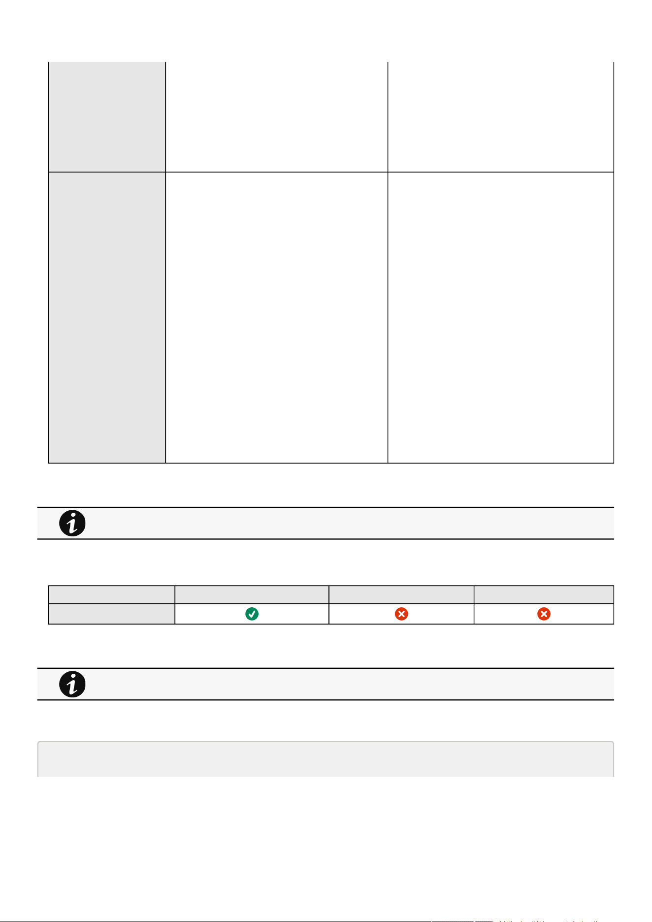
Settings
Contextual help of the web interface – 88
•
•
•
•
•
•
•
•
•
•
•
•
•
•
•
•
•
•
•
Temperature unit – °C (Celsius)/°F
(Fahrenheit)
Date format – MM-DD-YYYY / YYY-MM-
DD / DD-MM-YYY / DD.MM.YYY / DD/MM/
YYY / DD MM YYYY
Time format – hh:mm:ss (24h) / hh:mm:ss
(12h)
RADIUS Configure
Active – No
Retry number – 0
Primary server
Name – blank
Secret – blank
Address – blank
UDP port – 1812
Time out – 3
Secondary server
Name – blank
Secret – blank
Address – blank
UDP port – 1812
Time out – 3
Users preferences
Language – English
Temperature unit – °C (Celsius)
Date format – MM-DD-YYYY
Time format – hh:mm:ss (24h)
Configure
Active – Yes/No
Retry number – 0 to 128
Primary server
Name – 128 characters maximum
Address – 128 characters maximum
Secret – 128 characters maximum
UDP port – 1 to 65535
Time out – 3 to 60
Secondary server
Name – 128 characters maximum
Address – 128 characters maximum
Secret – 128 characters maximum
UDP port – 1 to 65535
Time out – 3 to 60
Users preferences
Language – English, French, German, Italian,
Japanese, Russian, Simplified Chinese,
Spanish, Traditional Chinese
Temperature unit – °C (Celsius)
Date format – MM-DD-YYYY
Time format – hh:mm:ss (24h)
3.7.3.4.1 For other settings
3.7.3.5 Access rights per profiles
Administrator Operator Viewer
Remote users
3.7.3.5.1 For other access rights
3.7.3.6 CLI commands
ldap-test
For other settings, see the Information>>>Default settings parameters section.
For other access rights, see the Information>>>Access rights per profiles section.

Settings
Contextual help of the web interface – 89
Description
Ldap-test help to troubleshoot LDAP configuration issues or working issues.
Help
Usage:ldap-test<command>[OPTION]...
Test LDAP configuration.
Commands:
ldap-test -h, --help, Display help page
ldap-test --checkusername <username> [--primary|--secondary] [-v]
Check if the user can be retrieve from the LDAP server
<username> Remote username to test
--primary Force the test to use primary server (optional)
--secondary Force the test to use secondary server (optional)
-v,--verbose Print the exchanges with LDAP server (optional)
ldap-test --checkauth <username> [--primary|--secondary] [-v]
Check if remote user can login to the card
<username> Remote username to test
-p,--primary Force the test to use primary server (optional)
-s,--secondary Force the test to use secondary server (optional)
-v,--verbose Print the exchanges with LDAP server (optional)
ldap-test --checkmappedgroups [--primary|--secondary] [-v]
Check LDAP mapping
-p,--primary Force the test to use primary server (optional)
-s,--secondary Force the test to use secondary server (optional)
-v,--verbose Print the exchanges with LDAP server (optional)
Quick guide for testing:
In case of issue with LDAP configuration, we recommend to verify the
configuration using the commands in the following order:
1. Check user can be retrieve on the LDAP server
ldap-test --checkusername <username>
2. Check that your remote group are mapped to the good profile
ldap-test --checkmappedgroups
3. Check that the user can connect to the card
ldap-test --checkauth <username>
logout
Description
Logout the current user.
Settings
Contextual help of the web interface – 90
•
•
•
•
•
Help
logout
<cr> logout the user
whoami
Description
whoami displays current user information:
Username
Profile
Realm
3.7.3.6.1 For other CLI commands
3.7.3.7 Troubleshooting
How do I log in if I forgot my password?
Action
Askyour administrator for password initialization.
If you are the mainadministrator, yourpasswordcan be reset manually by following steps described in the Servicing
the Network Management Module>>>Recovering main administrator password .
LDAP configuration/commissioning is not working
Refer to the section Servicing the Network Management Module>>>Commissioning/Testing LDAP .
3.7.3.7.1 For other issues
See the CLI commands in the Information>>>CLI section.
For details on other issues, see the Troubleshooting section.

Settings
Contextual help of the web interface – 91
3.7.3.8 Save and Restore
SRR
section
Sub
section
Sub section Sub section Sub section Settings Sub settings Possible values
LDAP ldap 1.0 settings enabled true/false
connectivity primaryServ
er
name String: refer to default
settings an possible
parameters for
constraints.
uri String: refer to default
settings an possible
parameters for
constraints.
port Unsigned number
secondarySe
rver
name String: refer to default
settings an possible
parameters for
constraints.
uri String: refer to default
settings an possible
parameters for
constraints.
port Unsigned number
userDomain nameAttribute String: refer to default
settings an possible
parameters for
constraints.
dn String: refer to default
settings an possible
parameters for
constraints.
groupDomai
n
nameAttribute String: refer to default
settings an possible
parameters for
constraints.
dn String: refer to default
settings an possible
parameters for
constraints.
bind dn String: refer to default
settings an possible
parameters for
constraints.
password plaintext String: refer to default
settings an possible
parameters for
constraints.
ciphered String: refer to default
settings an possible
parameters for
constraints.

Settings
Contextual help of the web interface – 92
•
•
•
security type 1: ssl
2: starttls
3: none
verifyCertificate true/false
mappings remoteGroup String: refer to default
settings an possible
parameters for
constraints.
profileName
administrators
viewers
operators
preferences language String: refer to default
settings an possible
parameters for
constraints.
dateFormat String: refer to default
settings an possible
parameters for
constraints.
timeFormat String: refer to default
settings an possible
parameters for
constraints.
temperatureUnit String: refer to default
settings an possible
parameters for
constraints.
licenceAgreement String: refer to default
settings an possible
parameters for
constraints.
SRR
section
Sub
section
Sub section Sub section Sub section Settings Sub settings Possible values
RADIUS radius 1.0 settings enabled true/false
connectivity
protocol
pap
chap
primaryServe
r
name String: refer to default
settings an possible
parameters for
constraints.
secret String: refer to default
settings an possible
parameters for
constraints.
uri String: refer to default
settings an possible
parameters for
constraints.
port Unsigned number
timeout Unsigned number
retryCount Unsigned number

Settings
Contextual help of the web interface – 93
secondarySe
rver
name String: refer to default
settings an possible
parameters for
constraints.
secret String: refer to default
settings an possible
parameters for
constraints.
uri String: refer to default
settings an possible
parameters for
constraints.
port Unsigned number
timeout Unsigned number
retryCount Unsigned number
nas identifier String: refer to default
settings an possible
parameters for
constraints.
ip String: refer to default
settings an possible
parameters for
constraints.
mappings profile String: refer to default
settings an possible
parameters for
constraints.
attribute Number
value Number
vendor Number
preferences language String: refer to default
settings an possible
parameters for
constraints.
dateFormat String: refer to default
settings an possible
parameters for
constraints.
timeFormat String: refer to default
settings an possible
parameters for
constraints.
temperatureUnit String: refer to default
settings an possible
parameters for
constraints.
licenceAgreement String: refer to default
settings an possible
parameters for
constraints.

Settings
Contextual help of the web interface – 94
•
•
•
•
•
•
•
•
•
•
3.7.3.8.1 Additional information
3.7.4 Network & Protocol
3.7.4.1 Network
3.7.4.1.1 IPv4
Press theEditbutton to configure the network settings, select either the Manual or DHCP settings option:
a Manual
Select Manual, and then enter the network settings if the network is not configured with a BootP or DHCP server.
Enter the IP Address.
The Network Modulemust have a unique IP address for use on a TCP/IP network.
Enter the netmask.
The netmask identifies the class of the sub-network the Network Module is connected to.
Enter the gateway address.
The gateway address allows connections to devices or hosts attached to different network segments.
b DHCP
Select dynamic DHCP to configure network parameters by a BootP or DHCP server.
If a response is not received from the server, the Network Module boots with the last saved parameters from the most recent
power up. After each power up, the Network Module makes five attempts to recover the network parameters.
3.7.4.1.2 IPv6
IPV6 status and the first three addresses are displayed.
Press theEditbutton toconfigure the network settings and get more information and access to the following IPV6 details.
a Current configuration
Address
Gateway
b Address settings
Enabled
Mode (Manual/DHCP)
Address
Prefix
Gateway
3.7.4.1.3 DNS/DHCP
The DNS is a hierarchical decentralized naming system for computers, services, or other resources connected to the Internet or a
private network.
Press theEditbutton toconfigure the network settings, select either the Static or Dynamic settings.
For details on Save and Restore, see the Save and Restore section.
Any modifications are applied after the Network Module reboots.

Settings
Contextual help of the web interface – 95
•
•
•
•
•
•
•
•
•
•
•
•
•
•
•
•
•
a Manual
Enter the Network Module Hostname.
Enter the Network Module Domain name.
Primary DNS server.
Enter the IP address of the DNS server that provides the translation of the domain name to the IP address.
Secondary DNS server.
Enter the IP address of the secondary DNS server that provides the translation of the domain name to the IP address when
the primary DNS server is not available.
b DHCP
Enter the Network Module Hostname.
3.7.4.1.4 Ethernet
A LAN is a computer network that interconnects computers within a limited area.
The available values for LAN configuration are listed below:
Auto negotiation
10Mbps -Half duplex
10Mbps -Full duplex
100Mbps - Half duplex
100Mbps -Full duplex
1.0 Gbps - Full duplex
Any modifications are applied after the nextNetwork Modulereboot.
3.7.4.2 Protocol
This tab contains settings for communication protocols used to get information from the devicethrough the network, such as https
for web browser.
3.7.4.2.1 HTTPS
Only https is available and http redirection can be disabled.
The default network port for https is 443. For additional security, the ports can be changed on this page.
PressSaveafter modifications.
3.7.4.2.2 Syslog
a Settings
This screen allows an administrator to configure up to two syslog servers.
To configure the syslog server settings:
1-Enablesyslog.
PressSaveafter modifications.
2-Configurethe syslog server:
Click the edit icon to access settings.
Enter or change the server name.
SelectYesin the Active drop-down list to activate the server.
Enter the Hostname and Port.
Select the Protocol – UDP/TCP.
In TCP, select the message transfer method – Octet counting/Non-transparent framing.
Since only https is available, port 80 is not supported.

Settings
Contextual help of the web interface – 96
•
•
•
•
•
•
•
•
•
•
•
•
•
Select the option Using Unicode BOM if needed.
PressSaveafter modifications.
3.7.4.3 Remote Monitoring Services
Thistile allows an administrator to configureand enable the Remote monitoring services on the Network Module.
To configure the remote monitoring connection settings:
1- Enable the Remote monitoring services
2- Configure the Proxy if needed.
3- Configure Advanced settings if so advised by Eaton service support and Save after modifications.
4- Save after modifications, a disclaimer will appear.
3.7.4.3.1 Status
Label Description
Connected The Network Module is connected and registered to the Remote Monitoring Service.
Data transmission is OK.
Disabled The Remote Monitoring Services is disabled.
To enable it, you must have a valid service contract. Please contact the local Eaton service team and enable the
Remote Monitoring Services on the Network Module.
Not connected The Remote Monitoring Services is enabled, the Network Module is not connected to it but connection
procedure has started.
Connecting The Network Module is connecting to the Remote Monitoring Services:
DNS is set correctly
Proxy is set correctly
Certificate verification is OK
Pending approval The Network Module is connected to the Remote Monitoring Services but not registered to it.
The Network Module must be registered by Eaton service team in the Remote Monitoring Services.
Connection lost The Network Module has lost the connection to the Remote Monitoring Services and will try to reconnect
automatically.
DNS name resolution error The Network Module connection to the Remote Monitoring Services has failed.
DNS is not set correctly or connection to it fails
Items to check with your network administrator:
DNS setting in the Network Module
DNS provided by the DHCP is working
DNS address in the Network Module is correct
Troubleshooting:
Switch to static DNS settings to troubleshoot
Proxy error The Network Module connection to the Remote Monitoring Services has failed.
Proxy is not set correctly in the network module or the proxy service does not allow this
connection.
Items to check with your network administrator:
Proxy URL is correctly set in the Network Module
Proxy allows connection to the Internet

Settings
Contextual help of the web interface – 97
•
•
•
•
•
•
•
•
•
•
Label Description
Proxy allows HTTPs connections to the Internet
Proxy does not use a custom certificate to intercept traffic
Troubleshooting:
Reboot the Network Module if above checking is OK and contact the service representative if
it still is not working.
Certificate error The Network Module connection to the Remote Monitoring Services has failed.
Certificate verification failed
Items to check with your network administrator:
Proxy does not use a custom certificate to intercept traffic
Troubleshooting:
Reboot the Network Module if above checking is OK and contact the service representative if
it still is not working.
Invalid credentials The Network Module connection to the Remote Monitoring Services has failed.
Authentication has failed
The Network Module is using invalid username/password to connect to the Remote Monitoring Services.
Items to check with your Eaton service contact:
Credentials set in the Network Module Advanced settings are correct.
Troubleshooting:
If above checking is OK, contact the service representative.
Connection error The Network Module connection to the Remote Monitoring Services has failed for another error.
Troubleshooting:
Contact the service representative.
3.7.4.4 Specifics
3.7.4.5 Default settings and possible parameters - Network & Protocol
Default setting Possible parameters
IPV4 Mode — DHCP Mode — DHCP/Manual (Address/Netmask/Gateway)
IPV6 Enable — checked
Mode — DHCP
Enabled — Active/Inactive
Mode — DHCP/Manual (Address/Prefix/Gateway)
DNS/DHCP Hostname —
device
-[MAC address]
Mode — DHCP
Hostname — 128 characters maximum
Mode :DHCP/Manual (Domain name/Primary DNS/
Secondary DNS)
Ethernet Configuration — Auto negotiation Configuration — Auto negotiation - 10Mbps -Half
duplex - 10Mbps -Full duplex - 100Mbps - Half duplex -
100Mbps -Full duplex - 1.0 Gbps - Full duplex
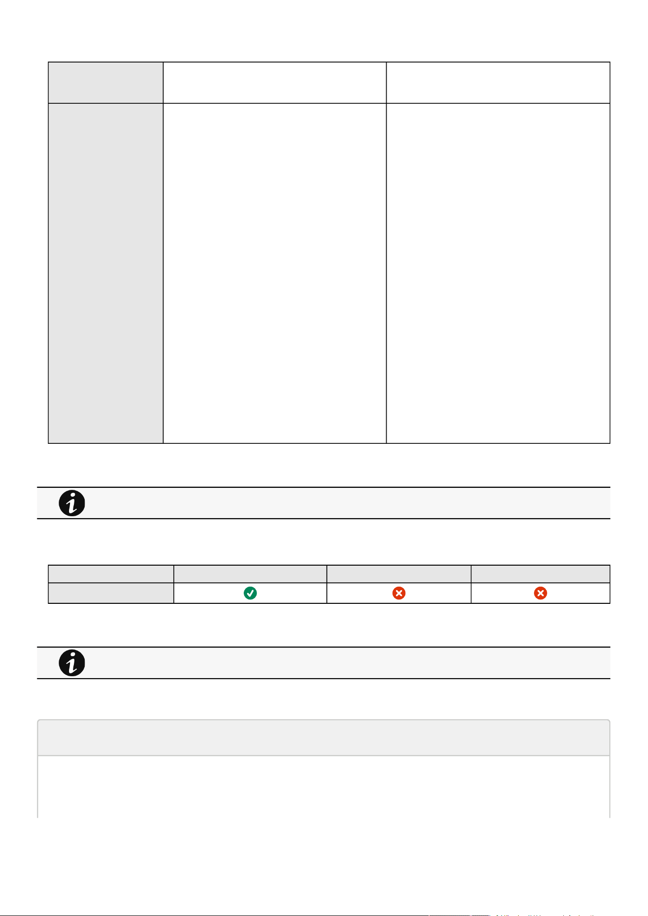
Settings
Contextual help of the web interface – 98
•
•
•
•
HTTPS Port — 443
Disable Port 80 (http) - Not disabled
Port — x-xxx
Disable Port 80 (http) - Disabled
Syslog Inactive
Server#1
Name – Primary
Status – Disabled
Hostname – empty
Port – 514
Protocol – UDP
Message transfer method – Non transparent
framing
Using unicode byte order mask (BOM)–
disabled
Server#2
Name – empty
Status – Disabled
Hostname – empty
Port – 514
Protocol – UDP
Message transfer method – DIsabled in UDP
Using unicode byte order mask (BOM)–
disabled
Inactive/Active
Server#1
Name – 128 characters maximum
Status – Disabled/Enabled
Hostname – 128 characters maximum
Port – x-xxx
Protocol – UDP/TCP
Message transfer method – Non transparent
framing
Using unicode byte order mask (BOM)–
disable/enable
Server#2
Name – 128 characters maximum
Status – Disabled/Enabled
Hostname – 128 characters maximum
Port – x-xxx
Protocol – UDP/TCP
Message transfer method (in TCP)– Octet
counting/Non transparent framing
Using unicode byte order mask (BOM)–
disable/enable
3.7.4.5.1 For other settings
3.7.4.6 Access rights per profiles
Administrator Operator Viewer
Network & Protocols
3.7.4.6.1 For other access rights
3.7.4.7 CLI commands
netconf
Description
Tools to display or change the network configuration of the card.
For other settings, see the Information>>>Default settings parameters section.
For other access rights, see the Information>>>Access rights per profiles section.

Settings
Contextual help of the web interface – 99
Help
For Viewer and Operator profiles:
netconf -h
Usage: netconf [OPTION]...
Display network information and change configuration.
-h, --help display help page
-l, --lan display Link status and MAC address
-4, --ipv4 display IPv4 Mode, Address, Netmask and Gateway
-6, --ipv6 display IPv6 Mode, Addresses and Gateway
-d, --domain display Domain mode, FQDN, Primary and Secondary DNS
For Administrator profile:
netconf -h
Usage:netconf[OPTION]...
Display network information and change configuration.
-h,--helpdisplayhelppage
-l,--landisplayLinkstatusandMACaddress
-d,--domaindisplayDomainmode,FQDN,PrimaryandSecondaryDNS
-4,--ipv4displayIPv4Mode,Address,NetmaskandGateway
-6,--ipv6displayIPv6Mode,AddressesandGateway
Setcommandsareusedtomodifythesettings.
-s,--set-lan<linkspeed>
Linkspeedvalues:
autoAutonegotiation
10hf10Mbps-Halfduplex
10ff10Mbps-Fullduplex
100hf100Mbps-Halfduplex
100ff100Mbps-Fullduplex
1000ff1.0Gbps-Fullduplex
-f,--set-domainhostname<hostname>setcustomhostname
-f,--set-domain<mode>
Modevalues:
-setcustomNetworkaddress,NetmaskandGateway:
manual<domainname><primaryDNS><secondaryDNS>
-automaticallysetDomainname,PrimaryandSecondaryDNS
dhcp
-i,--set-ipv4<mode>
Modevalues:
-setcustomNetworkaddress,NetmaskandGateway
manual<network><mask><gateway>
-automaticallysetNetworkaddress,NetmaskandGateway
dhcp
-x,--set-ipv6<status>
Statusvalues:
-enableIPv6
enable
-disableIPv6
disable
-x,--set-ipv6<mode>
Modevalues:
-setcustomNetworkaddress,PrefixandGateway

Settings
Contextual help of the web interface – 100
manual<network><prefix><gateway>
-automaticallysetNetworkaddress,PrefixandGateway
router
Examples of usage:
-> Display Link status and MAC address
netconf-l
-> Set Auto negotiation to Link
netconf--set-lanauto
-> Set custom hostname
netconf--set-domainhostnameups-00-00-00-00-00-00
-> Set Adress, Netmask and Gateway
netconf--set-ipv4manual192.168.0.1255.255.255.0192.168.0.2
-> Disable IPv6
Examples of usage
-> Display Link status and MAC address
netconf -l
-> Set Auto negotiation to Link
netconf -s auto
-> Set custom hostname
netconf -f hostname ups-00-00-00-00-00-00
-> Set Adress, Netmask and Gateway
netconf -i manual 192.168.0.1 255.255.255.0 192.168.0.2
-> Disable IPv6
netconf -6 disable
ping and ping6
Description
Ping and ping6 utilities are used to test network connection.
Help
ping
The ping utility uses the ICMP protocol's mandatory ECHO_REQUEST datagram
to elicit an ICMP ECHO_RESPONSE from a host or gateway. ECHO_REQUEST
datagrams (``pings'') have an IP and ICMP header, followed by a ``struct
timeval'' and then an arbitrary number of ``pad'' bytes used to fill out
the packet.
-c Specify the number of echo requests to be sent
-h Specify maximum number of hops
<Hostname or IP> Host name or IP address
Settings
Contextual help of the web interface – 101
ping6
The ping6 utility uses the ICMP protocol's mandatory ECHO_REQUEST datagram
to elicit an ICMP ECHO_RESPONSE from a host or gateway. ECHO_REQUEST
datagrams (``pings'') have an IP and ICMP header, followed by a ``struct
timeval'' and then an arbitrary number of ``pad'' bytes used to fill out
the packet.
-c Specify the number of echo requests to be sent
<IPv6 address> IPv6 address
traceroute and traceroute6
Description
Traceroute and traceroute6 utilities are for checking the configuration of the network.
Help
traceroute
-h Specify maximum number of hops
<Hostname or IP> Remote system to trace
traceroute6
-h Specify maximum number of hops
<IPv6 address> IPv6 address
3.7.4.7.1 For other CLI commands
3.7.4.8 Save and Restore
SRR section SRR sub section Settings Sub settings Possible values
Ethernet Network link config 0
DNS/DHCP domain hostname String: refer to default
settings an possible
parameters for
constraints.
mode *
manual domainName String: refer to default
settings an possible
See the CLI commands in the Information>>>CLI section.

Settings
Contextual help of the web interface – 102
parameters for
constraints.
dns preferredServer
alternateServer
xx.xxx.xx.xx
xx.xxx.xx.xx
IPv4 ipv4 enabled
dhcpEnabled
true/false
true/false
manual address
subnetMask
gateway
xx.xxx.xx.xx
xxx.xxx.xxx.x
xx.xxx.xx.x
IPv6 ipv6 enabled true/false
addressing *
mode *
manual address *
prefixLength *
gateway *
Syslog syslog certificateData ca
trustedClient
*
enabled true/false
servers name String: refer to default
settings an possible
parameters for
constraints.
enabled true/false
hostname String: refer to default
settings an possible
parameters for
constraints.
protocol 1: UDP
2: TCP
port Number: refer to
default settings an
possible parameters
for constraints.
tcpFraming 1: TRADITIONAL
2:
OCTET_COUNTING
usingByteOrderMask true/false
security ssl *
verifyTlsCert true/false
name String: refer to default
settings an possible
parameters for
constraints.
enabled true/false

Settings
Contextual help of the web interface – 103
•
•
•
hostname String: refer to default
settings an possible
parameters for
constraints.
protocol 1: UDP
2: TCP
port Number: refer to
default settings an
possible parameters
for constraints.
tcpFraming 1: TRADITIONAL
2:
OCTET_COUNTING
usingByteOrderMask true/false
security ssl *
verifyTlsCert true/false
HTTPS webserver https enabled true/false
port Number: refer to
default settings an
possible parameters
for constraints.
3.7.4.8.1 Additional information
3.7.5 SNMP
This tab contains settings for SNMP protocols used for network management systems.
3.7.5.1 SNMP tables
SNMP monitoring Battery status, power status, events, and traps are monitored using third-party SNMP managers.
To query SNMP data, you do not need to add SNMP Managers to the Notified Application page.
To set-up SNMP managers:
Configure the IP address.
Select SNMP v1 or v1 and v3.
Compile the MIB you selected to be monitored by the SNMP manager.
List of supported MIBs:
xUPS MIB | Standard IETF UPS MIB (RFC 1628) | Sensor MIB
Press theSupported MIBsbutton to download the MIBs.
For details on Save and Restore, see the Save and Restore section.
Changes to authentication settings need to be confirmed by entering a valid password for the active user account.
The default port for SNMP is 161 and normally this should not be changed. Some organizations prefer to use non-
standard ports due to cybersecurity, and this field allows that.

Settings
Contextual help of the web interface – 104
•
•
•
•
•
•
•
•
•
•
•
3.7.5.1.1 Settings
This screen allows an administrator to configure SNMP settings for computers that use the MIB to request information from the
Network Module.
Default ports for SNMP are 161 (SNMP v1 and v3, set/get) and 162 (traps). These ports can be changed on the settings screenfor
additional security.
To configure the SNMP settings:
a Enable theSNMP agent
In addition to this also v1 and/or v3 must be enabled, along with appropriate communities and activated user accounts to allow
SNMP communication.
PressSaveafter modifications.
b Configure the SNMP V1 settings:
1.Click the edit icon on either Read Only or Read/Write account to access settings:
2. Enter the SNMP Community Read-Only string. The Network Module and the clients must share the same community name to
communicate.
3. SelectActivein the Enabled drop-down list to activate the account.
4. Access level is set to display information only.
c Configure the SNMP V3 settings:
1.Click the edit icon on either Read Only or Read/Write account to access settings:
2. Edit the user name.
3. Select Activein the Enabled drop-down list to activate the account.
4. Select access level.
Read only—The user does not use authentication and privacy to access SNMP variables.
Read/Write—The user must use authentication, but not privacy, to access SNMP variables.
5. Select the communication security mechanism.
Auth, Priv—Communication with authentication and privacy.
Auth, No Priv—Communication with authentication and without privacy.
No Auth, No Priv—Communication without authentication and privacy.
6. If Auth is selected on the communication security mechanism, select the Authentication algorithms.
SHA— SHA1 is not recommended as it is not secured.
SHA256—fill in password and privacy keys. The password can be between 8 and 24 characters and use a combination of
alphanumeric and the following special characters<>&@#%_=:;,./?|$*.
SHA384—fill in password and privacy keys. The password can be between 8 and 24 characters and use a combination of
alphanumeric and the following special characters<>&@#%_=:;,./?|$*.
SHA512—fill in password and privacy keys. The password can be between 8 and 24 characters and use a combination of
alphanumeric and the following special characters<>&@#%_=:;,./?|$*.
AES / AES192 / AES256
7. If Priv is selected on the communication security mechanism, select the Privacy algorithms.
AES— fill in password and privacy keys. The password can be between 8 and 24 characters and use a combination of
alphanumeric and the following special characters<>&@#%_=:;,./?|$*.
It is recommended to set SHA256/SHA384/SHA512 with the AES192/AES256 Privacy algorithms.
It is recommended to set AES192/AES256 with the SHA256/SHA384/SHA512 Authentication algorithms.

Settings
Contextual help of the web interface – 105
•
•
•
•
•
•
•
•
•
•
•
•
•
•
•
•
•
•
•
AES192—fill in password and privacy keys. The password can be between 8 and 24 characters and use a combination of
alphanumeric and the following special characters<>&@#%_=:;,./?|$*.
AES256—fill in password and privacy keys. The password can be between 8 and 24 characters and use a combination of
alphanumeric and the following special characters<>&@#%_=:;,./?|$*.
8. Enter your own login password and clickSave.
3.7.5.2 Trap receivers
The table shows all the trap receivers and includes the following details:
Application name
Host
Protocol
Port
Status:Active/Inactive/Error(configuration error)
3.7.5.2.1 Actions
a Add
1.Press theNewbutton to create new trap receivers.
2. Set following settings:
Enabled – Yes/No
Application name
Hostname or IP address
Port
Protocol– V1/V3
Trap community (V1) / User (V3)
3. Press theSAVEbutton.
b Remove
Select a trap receiver and press theDeletebutton to remove it.
c Edit
Press the pen iconto edit trap receiver information and access to its settings:
d Test trap
Press theTest trapbutton to send the trap test to all trap receivers.
Separate window provides the test status with following values:
In progress
Request successfully sent
invalid type
3.7.5.3 Specifics
3.7.5.4 Link to SNMP traps
UPS Mib
ATS Mib
Sensor Mib
For details on SNMP trap codes, see the Information>>>SNMP traps
section.

Settings
Contextual help of the web interface – 106
•
•
•
•
•
•
•
•
3.7.5.5 Default settings and possible parameters - SNMP
Default setting Possible parameters
SNMP Activate SNMP — disabled
Port — 161
SNMP V1 — disabled
Community #1 — public
Enabled — Inactive
Access — Read only
Community #2 — private
Enabled — Inactive
Access — Read/Write
SNMP V3 — enabled
User #1 — readonly
Enabled — Inactive
Access — Read only
Authentication — Auth (SHA-1)
Password — empty
Confirm password — empty
Privacy — Secured - AES
Key — empty
Confirm key — empty
User#2 — readwrite
Enabled — Inactive
Access — Read/Write
Authentication — Auth (SHA-1)
Password — empty
Confirmpassword — empty
Privacy — Secured - AES
Key — empty
Confirm key — empty
Activate SNMP — disable/enable
Port — x-xxx
SNMP V1 — disable/enable
Community #1 — 128 characters maximum
Enabled — Inactive/Active
Access — Read only
Community #2 — 128 characters
maximum
Enabled — Inactive/Active
Access — Read/Write
SNMP V3 — disable/enable
User #1 — 32 characters maximum
Enabled — Inactive/Active
Access — Read only/Read-Write
Authentication — Auth (SHA-1)/None
Password — 128 characters maximum
Confirm password — 128 characters
maximum
Privacy — Secured - AES/None
Key — 128 characters maximum
Confirm key — 128 characters maximum
User#2 — 32 characters maximum
Enabled — Inactive/Active
Access — Read only/Read-Write
Authentication — Auth (SHA-1)/None
Password — 128 characters maximum
Confirmpassword — 128 characters
maximum
Privacy — Secured - AES/None
Key — 128 characters maximum
Confirm key — 128 characters maximum
Trap receivers No trap Enabled — No/Yes
Application name — 128 characters maximum
Hostname or IP address — 128 characters maximum
Port — x-xxx
Protocol — V1
Trap community — 128 characters maximum
3.7.5.5.1 For other settings
3.7.5.6 Access rights per profiles
Administrator Operator Viewer
SNMP
For other settings, see the Information>>>Default settings parameters section.

Settings
Contextual help of the web interface – 107
3.7.5.6.1 For other access rights
3.7.5.7 Troubleshooting
SNMPv3 password management issue with Save and Restore
Affected FW versions
This issue affects SNMPconfigurationdone on versions prior to 1.7.0 when applied to versions 1.7.0 or above.
Symptom
SNMPv3 connectivity is not properly working after a restore settings on a 1.7.0 version or above.
Cause
The SNMPv3 wasconfiguredprior to 1.7.0.
In that case, SNMPv3 configuration is not well managed by the Save and by the Restore settings.
Action
Reconfigureyour SNMPv3 users and passwords on versions 1.7.0 or above and Save the settings.
The SNMPv3 configuration can then be Restored.
3.7.5.7.1 For other issues
3.7.5.8 Save and Restore
SRR section SRR sub section Settings Sub settings Example
SNMP snmp enabled true
port Number: refer to default
settings an possible
parameters for constraints.
v1 enabled true
communities readOnly
Name String: refer to default
settings an possible
parameters for constraints.
Enabled
readWrite
For other access rights, see the Information>>>Access rights per profiles section.
For details on other issues, see the Troubleshooting section.

Settings
Contextual help of the web interface – 108
Name String: refer to default
settings an possible
parameters for constraints.
Enabled true/false
v3 enabled true
users name String: refer to default
settings an possible
parameters for constraints.
allowWrite true/false
enabled true/false
auth
enabled true/false
algorithm *
password
plaintext String: refer to default
settings an possible
parameters for constraints.
cyphered -
priv
enabled true/false
algorithm *
password
plaintext String: refer to default
settings an possible
parameters for constraints.
cyphered -
name String: refer to default
settings an possible
parameters for constraints.
allowWrite true/false
enabled true/false
auth
enabled true/false
algorithm *
password
plaintext String: refer to default
settings an possible
parameters for constraints.
cyphered -
priv
enabled true/false
algorithm *
password
plaintext String: refer to default
settings an possible
parameters for constraints.
cyphered -

Settings
Contextual help of the web interface – 109
•
•
•
•
•
•
•
traps receivers name String: refer to default
settings an possible
parameters for constraints.
host *
port Number: refer to default
settings an possible
parameters for constraints.
community *
protocol 1 : V1
3 : V3
user *
enabled true/false
3.7.5.8.1 Additional information
3.7.6 Industrial protocols
3.7.6.1 Modbus
3.7.6.1.1 Configuration
a Modbus RTU
For instructions on connecting Modbus RTU see the sectionInstalling the Network Management Module>>>Wiring the RS-485
Modbus RTU terminal>>>Configuring the termination.
The following Modbus RTUsettings are configurable:
Enable
Baud rate
Parity
Stop bits
b Modbus TCP
The followingModbus TCPsettings are configurable:
Enable
Port
3.7.6.1.2 Mapping configuration
a Mapping configuration table
The table shows all the mapping configuration and includes the following details:
Custom name
For details on Save and Restore, see the Save and Restore section.
This section is only for the Modbus Network ModuleINDGW
For instructions on configuring Modbus see the sectionInstalling the Network Management
Module>>>Configuring Modbus.

Settings
Contextual help of the web interface – 110
•
•
•
•
•
•
•
•
•
•
•
•
•
•
•
•
•
•
•
•
•
•
•
•
•
•
•
MAP
Transport
Access
Illegal read
IP filtering
Coil/register base address shift
b Actions
Add
Press theNewbutton to create new mapping configuration.
Remove
Select a mapping configuration and press theDeletebutton to remove it.
Edit
Press the pen logoto edit mapping configuration:
You will get access to the following settings:
Custom name
MAP
Transport
Device ID & conventional alternative ids you may choose
MAP Conventional IDs
Uid-0 0, 1 , 247, 255
Uid 244 244
Uid 245 245, 253
Uid 140 144
Illegal read behaviour
Coil/register base address shift
IP filtering
Supported MAPs
Press theSupported MAPsbutton to download the MAPs.
Mapping file content:
Address (hex, 0/1-based): register address in hexadecimal
Address (dec, 0/1 based): register address in decimal
Type: Register/Discrete
Size in bytes
Number of Modbus registers
Writable: True/False
Representation: Int16/Uint16/String/Boolean/...
Name
Description
Unit
Status to 0: status when the register equal 0
Status to 1:status when the register equal 1
Available: True/False –Shows if the register is available on current Device
Value: Shows current value of the register on current Device
File is generated in real time and will take into account the Device capabilities and values at the time of the
generation.
Table in the downloaded file will show all possible registers, only the one showing Available equal to True will be
supported by your system.

Settings
Contextual help of the web interface – 111
•
•
•
•
•
•
•
3.7.6.2 BACnet
BACnet/IP communication provides read-only data from Building Automation Systems (BASs) so that the Network Module can be
easily integrated in a BAS alongside other BACnet /IP capable devices.
3.7.6.2.1 Configuration
The followingBACnetsettings are configurable or displayed:
Enable BACnet IP
Device Id–Must be unique in BACnet network. Automatically generated from Ethernet MAC address to prevent collisions.
Device Name–Must be unique in BACnet network. Automatically generated from manufacturer name and serial number to
prevent collisions.
Device connection control password –Password is required with DCC commands; if it has not been configured, then these
commands will not be authorized.
Enable Broadcast management device– To register as a Foreign Device with the BACnet BBDM indicated in IP address field.
BBDM BACnet/IP device–Automatically generated and modifiable, IPv4 address of the BBMD we will register with.
BBDM Time to live– The BBMD time to live (in seconds), we must "ping" the BBMD we are registered with within this time.
a Actions
Get EPICS file
An electronic protocol implementation conformance statement (EPICS) file provides verification that devices meet BACnet
standards for objects and services.
This allows EPICS files to provide data to software test programs and for system configuration at the BAS.
Press the Get EPICS filebutton to download the EPICs.
3.7.6.3 Specifics
3.7.6.4 Default settings and possible parameters - Industrial protocols
Default setting Possible parameters
Modbus RTU Modbus RTU — Inactive
Baud rate (bps) — 19200
Parity — Even
Stop bits – 1
Modbus RTU — Inactive/Active
Baud rate (bps) —
1200/2400/4800/9600/19200/38400/57600/115200
Parity — None/Even/Odd
Stop bits – 1/2
Default setting Possible parameters
Modbus TCP Modbus TCP — Inactive
Port — 502
Modbus TCP — Inactive/Active
Port — x-xxx
Default setting Possible parameters
File is generated in real time and will take into account the Device capabilities and values at the time of the
generation.
The file is in text protocol information (.TPI) format and is machine and human readable, open it with any text reader
to view it.
Modbus and BACnet settings are only for the INDGW Network Module.
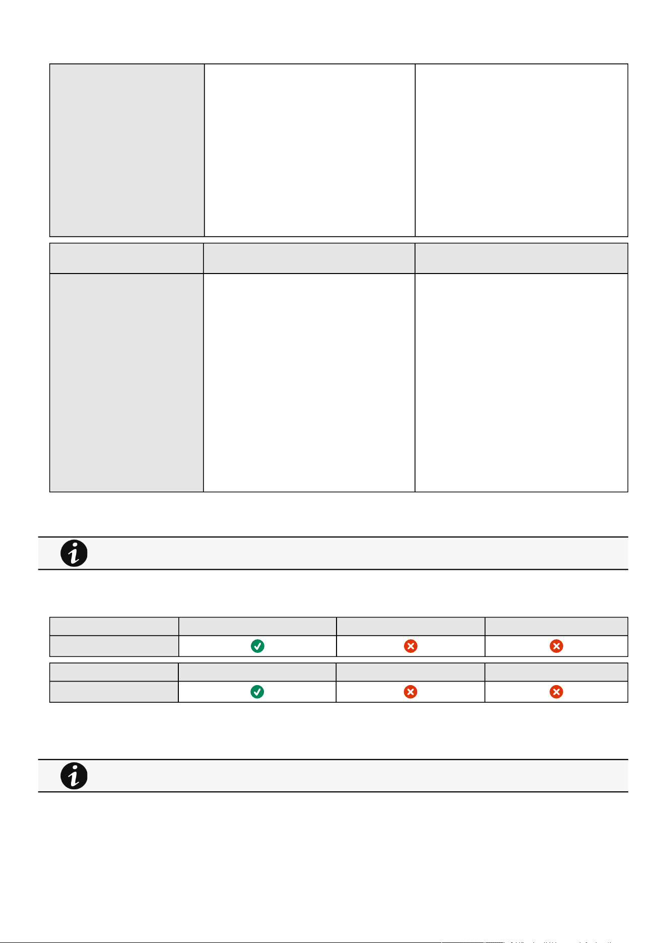
Settings
Contextual help of the web interface – 112
Mapping configuration No mapping Custom name – 128 characters maximum
Map – Eaton ModbusMS compatible, Eaton
PowerXpert UID 0 compatible, Card System
Information
Transport – RTU/TCP
Access – None/Read only/Read/Write
Illegal read behaviour – Return exception/Return
zeros
IP filtering – IP address
Coil/register base address shift – No shift/Shift by 1
(JBUS)
Default setting Possible parameters
BACnet BACnet IP — Inactive BACnet IP — Inactive/Active
Device Id — Automatically generated, must be
unique, 4194304 characters maximum
Device Name — Automatically generated, must be
unique, 1-255 characters maximum, only Latin
letters, numbers, spaces, '_' and '!' symbols
Device connection control password — 6-20
characters maximum
Local port — 1-65535 characters maximum (as all
the other UDP and TCP ports)
MAC address — MAC address format
Broadcast management device — Inactive/Active
BBMD BACnet/IP device — IP address format
BBMD Time to live — 30-1800 seconds
3.7.6.4.1 For other settings
3.7.6.5 Access rights per profiles
Administrator Operator Viewer
Industrial protocols/Modbus*
Administrator Operator Viewer
Industrial protocols/BACnet*
*for INDGW only
3.7.6.5.1 For other access rights
For other settings, see the Information>>>Default settings parameters section.
For other access rights, see the Information>>>Access rights per profiles section.
Settings
Contextual help of the web interface – 113
•
•
•
•
•
•
•
•
•
•
•
•
3.7.6.6 CLI commands
modbus_message_display
Description
modbus_message_display restarts the server and displays Modbus message. This command allow you to verifiy that Modbus
server is working as expected.
Help
modbus_message_display
--help Restart server and display modbus message
-h Restart server and display modbus message
modbus_statistics
Description
modbus_statistics displays Modbus RTU and TCP status and server statistics:
Bus character overrun count
Bus frame error count
Bus parity error count
Buffer overrun count
Bus message count
Valid message count
CRC error count
Incoming message count
Discarded message count
Processed message count
Success returned count
Exception returned count
Help
modbus_statistics
Display modbus server statistics
-h, --help Display the help page.
-r, --reset Reset modbus server statistics.
This section is only for the Modbus Network Module INDGW
This section is only for the Modbus Network Module INDGW
Settings
Contextual help of the web interface – 114
•
•
•
•
The counter from A1.1 to A1.4 are reset only at startup of the
server.
3.7.6.6.1 For other CLI commands
3.7.6.7 Troubleshooting
Modbus communication doesn't work
Symptoms
Communication doesn't work
Possible cause
Incorrect communication parameters.
Verify that the communication parameters are set to the desired settings.For Modbus TCP configuration refer to the
section Contextual help>>>Settings>>>Modbus>>>Modbus TCP .
For Modbus RTU configuration refer to the section Contextual help>>>Settings>>>Modbus>>>Modbus RTU .
RS-485 communication lines are reversed
For two-wire networks refer to the section Installing the Network Management Module>>>Wiring the RS-485 Modbus
RTU terminal>>>Two-wire networks .
For four-wire networks refer to the section Installing the Network Management Module>>>Wiring the RS-485 Modbus
RTU terminal>>>Four-wire networks .
If the Modbus Card is the last device installed in the network chain or the length of the network cable is excessive,
termination needs to be enabled.
Verify the termination settings and refer to the section Installing the Network Management Module>>>Wiring the
RS-485 Modbus RTU terminal>>>Configuring the termination .
3.7.6.7.1 For other issues
3.7.6.8 Save and Restore
SRR section Settings Sub settings Possible values
See the CLI commands in the Information>>>CLI section.
Refer to the section Servicing the Network Management Module>>>Configuring Modbus to get configuration
and testing information.
For details on other issues, see the Troubleshooting section.

Settings
Contextual help of the web interface – 115
Modbus modbus data tcp enabled true/false
port Number: refer to default settings an possible
parameters for constraints.
SRR section Settings Sub settings Possible values
Modbus modbus data rtu enabled true/false
baudrate 1: 1200pbs
2: 2400bps
3: 4800bps
4: 9600bps
5: 19200bps
6: 38400bps
7: 57600bps
8: 115200bps
parity 1: None
2: Even
3: Odd
stopBits 1: 1 Stop bit
2: 2 Stop bits
SRR section Settings Sub settings Possible values
Modbus modbus data mapping configurations name String: refer to default settings an possible
parameters for constraints.
map Eaton ModbusMS compatible, Eaton PowerXpert UID
0 compatible, Card System Information
transport 1: RTU2: TCP
transportFilter *
deviceId Number: refer to default settings an possible
parameters for constraints.
access 0: None
1: Read only
3: Read/Write
illegalReadBehavior 1: Return exception
2: return zeros
addressBaseShift Shift value (1,2,5,..)
name
map
transport
transportFilter
deviceId
access
illegalReadBehavior
addressBaseShift
Same as above

Settings
Contextual help of the web interface – 116
•
•
•
•
Bacnet bacnet configuration access enabled true/false
port Number: refer to default settings an possible
parameters for constraints.
bbmd enabled true/false
ipv4Address xxx.xxx.xxx.xxx
timeToLive number of seconds
servicesEnabled true/false
device deviceId *
deviceName *
dccPassword *
3.7.6.8.1 Additional information
3.7.7 Certificate
3.7.7.1 Pairing with clients
During the selected timeframe, new connections to the Network Module are automatically trusted and accepted.
After automatic acceptance, make sure that all listed clients belong to your infrastructure. If not, access may be revoked using the
Delete button.
The use of this automatic acceptance should be restricted to a secured and trusted network.
For maximum security, we recommend followingone of the two methodson the certificate settings page:
Import agent's certificates manually.
Generate trusted certificate for both agents and Network Module using your own PKI.
3.7.7.1.1 Actions
a Start
Starts the pairing window during the selected timeframe or until it is stopped.
Time countdown is displayed.
b Stop
Stopsthe pairing window.
3.7.7.2 Local certificates
Manage local certificates by :
Generating CSR and import certificates signed by the CA.
Generating new self-signed certificates.
For details on Save and Restore, see the Save and Restore section.
For details on pairing instructions, follow the linkpairing instructionsin the tile or see theServicing the Network
Management Module
>>>Pairing agent to the Network Module
section.

Settings
Contextual help of the web interface – 117
•
•
•
•
•
•
•
•
•
•
•
•
•
•
•
•
•
•
•
3.7.7.2.1 Local certificates table
The table shows the following information for each local certificate.
Used for
Issued by
Valid from
Expiration
Status — valid, expires soon, or expired
3.7.7.2.2 Actions
a Revoke
This action will take the selected certificate out of use.
Select the certificate to revoke, and then press theRevokebutton.
A confirmation window appears, pressContinueto proceed, this operation cannot be recovered.
b Export
Exports the selected certificate on your OS browser window.
c Configure issuer
Press theConfigure issuerbutton.
A configuration window appears to edit issuer data.
Common name (CN)
Country (C)
State or Province (ST)
City or Locality (L)
Organization name (O)
Organization unit (OU)
Contact email address
PressSave button.
d Edit
Press the pen logo:
You will get access to the following:
Certificate summary
Actions
Generate a new self-signed certificate
Generate a certificate signing request ( CSR )
Generate a certificate signing request excluding IP addresses ( CA / CB compliance )
Import certificate (only available when CSR is generated).
Details
Revoke will replace current certificate by a new self-signed certificate.
This may disconnect connected applications:
- Web browsers
- Shutdown application
- Monitoring application
The certificate that is taken out of use with the revoke action cannot be recovered.
Issuer configuration will be applied only after the revoke of the certificate.
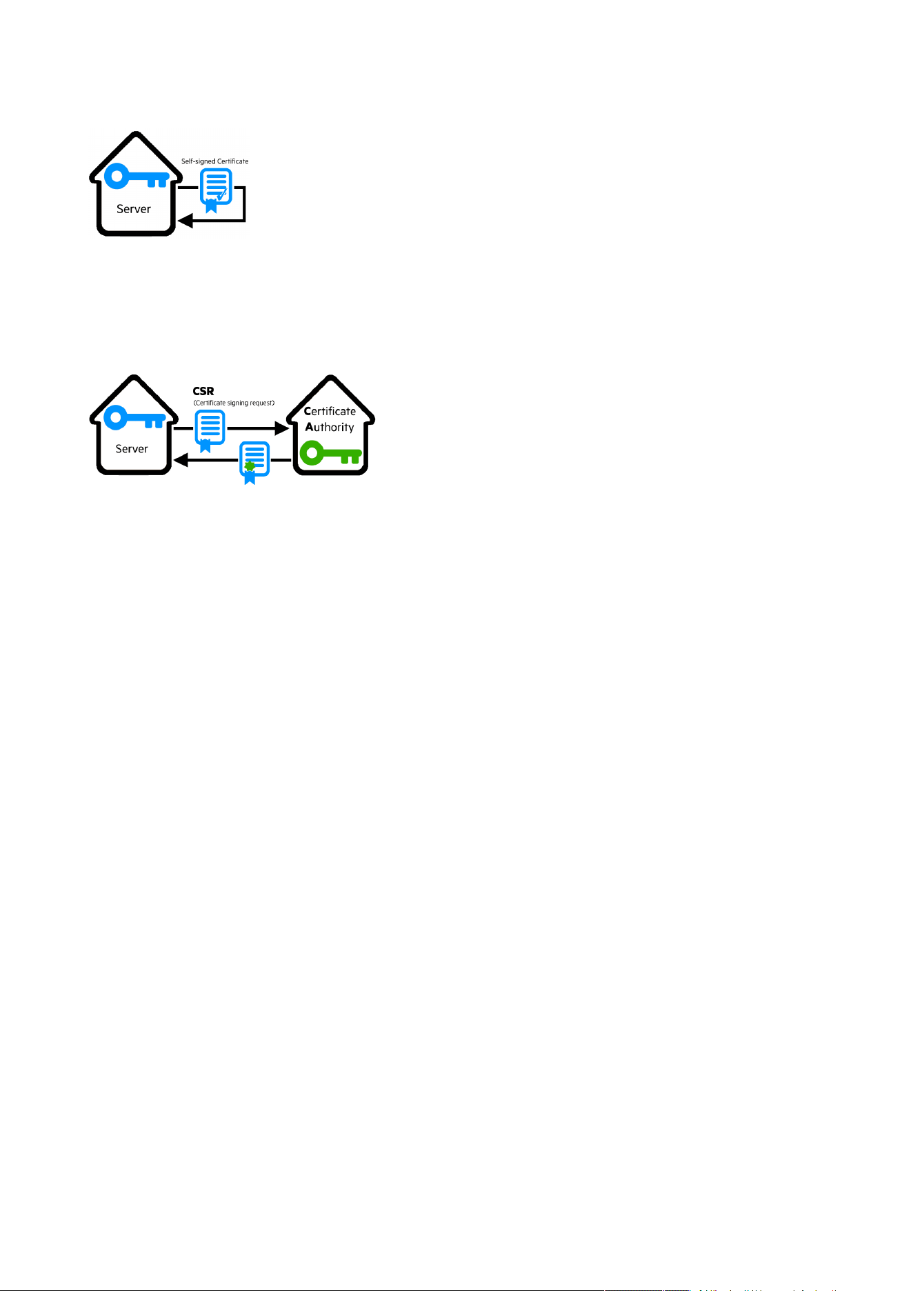
Settings
Contextual help of the web interface – 118
•
•
•
•
•
•
e Generate a new self-signed certificate
To replace a selected certificate with a new self-signed certificate.
This may disconnect applications such as a Web browser, shutdown application, or monitoring application.
This operation cannot be recovered.
f Create new certificates:
g CSR
PressGenerate Signing Request button in the in the certificate edition.
The CSR is automatically downloaded.
CSR must be signed with the CA, which is managed outside the card.
h Import certificate
When the CSR is signed by the CA, it can be imported into the Network Module.
When the import is complete, the new local certificate information is displayed in the table.
3.7.7.3 Certificate authorities (CA)
Manages CAs.
3.7.7.3.1 CA table
The table displays certificate authorities with the following details:
Used for
Issued by
Issued to
Valid from
Expiration
Status— valid, expires soon, or expired
3.7.7.3.2 Actions
a Import
When importing the CA, you must select the associated service, and then upload process can begin through the OS browser
window.
b Revoke
Select the certificate to revoke, and then press the Revoke button.

Settings
Contextual help of the web interface – 119
•
•
•
•
•
•
A confirmation window appears, press Continue to proceed, this operation cannot be recovered.
Export
Exports the selected certificate on yourOS browser window.
c Edit
Press the pen logoto access to the certificate summary:
3.7.7.4 Trusted remote certificates
The table shows the following information for each trusted remote certificate.
Used for
Issued by
Issued to
Valid from
Expiration
In case a certificate expires, the connection with the client will be lost. If this happens, the user will have to recreate the
connection and associated certificates.
Status— valid, expires soon, or expired
3.7.7.4.1 Actions
a Import
When importing the client certificate, you must select the associated service, and then upload process can begin through the OS
browser window.
b Revoke
Select the certificate to revoke, and then press theRevokebutton.
A confirmation window appears, pressContinueto proceed, this operation cannot be recovered.
c Edit
Press the pen logoto the certificate summary:
3.7.7.5 Specifics
3.7.7.6 Default settings and possible parameters - Certificate
Default setting Possible parameters
Local certificates Common name — Service + Hostname + selfsigned
Country — FR
State or Province — 38
City or Locality — Grenoble
Organization name — Eaton
Organization unit — Power quality
Contact email address — blank
Common name — 64 characters maximum
Country — Country code
State or Province —64 characters maximum
City or Locality —64 characters maximum
Organization name —64 characters maximum
Organization unit —64 characters maximum
Contact email address —64 characters maximum
Settings
Contextual help of the web interface – 120
3.7.7.6.1 For other settings
3.7.7.7 Access rights per profiles
Administrator Operator Viewer
Certificate
3.7.7.7.1 For other access rights
3.7.7.8 CLI commands
certificates
Description
Allows to manage certificates through the CLI.
Help
certificates <target> <action> <service_name>
<target> :
- local
<action> :
- print: provides a given certificate detailed information.
- revoke: revokes a given certificate.
- export: returns a given certificate contents.
- import: upload a given certificate for the server CSR. This will replace the
CSR with the certificate given.
- csr: get the server CSR contents. This will create the CSR if not already
existing.
<service_name>: mqtt/syslog/webserver
Examples of usage
From a linux host:
printover SSH:sshpass -p $PASSWORD ssh $USER@$CARD_ADDRESS certificates local print $SERVICE_NAME
revoke over SSH:sshpass -p $PASSWORD ssh $USER@$CARD_ADDRESS certificates localrevoke $SERVICE_NAME
exportover SSH:sshpass -p $PASSWORD ssh $USER@$CARD_ADDRESS certificates localexport $SERVICE_NAME
importover SSH:cat$FILE | sshpass -p $PASSWORD ssh $USER@$CARD_ADDRESS certificates localimport
$SERVICE_NAME
csr over SSH:sshpass -p $PASSWORD ssh $USER@$CARD_ADDRESS certificates localcsr mqtt
For other settings, see the Information>>>Default settings parameters section.
For other access rights, see the Information>>>Access rights per profiles section.
Settings
Contextual help of the web interface – 121
•
•
•
•
•
•
•
•
•
•
From a Windows host:(plink tools from putty is required)
print over SSH:plink $USER@$CARD_ADDRESS -pw$PASSWORD -batch certificates local print $SERVICE_NAME
revoke over SSH:plink $USER@$CARD_ADDRESS -pw $PASSWORD -batch certificates localrevoke $SERVICE_NAME
export over SSH:plink $USER@$CARD_ADDRESS -pw$PASSWORD -batch certificates localexport $SERVICE_NAME
import over SSH:type $FILE | plink $USER@$CARD_ADDRESS -pw $PASSWORD -batch certificates localimport
$SERVICE_NAME
csrover SSH:plink $USER@$CARD_ADDRESS -pw $PASSWORD -batch certificates localcsr mqtt
Where:
$USER is user name (the user shall have administrator profile)
$PASSWORD is the user password
$PASSPHRASE is any passphrase to encrypt/decrypt sensible data.
$CARD_ADDRESS is IP or hostname of the card
$FILE is a certificate file
$SERVICE_NAME is the name one of the following services : mqtt/ syslog / webserver.
3.7.7.8.1 For other CLI commands
3.7.7.9 Troubleshooting
Software is not able to communicate with the Network module
Symptoms
In the Network Module,in Contextual help>>>Protection>>>Agent list>>>Agent list table , agent is showing "Lost" as
a status.
In the Network Module,in Contextual help>>>Settings>>>Certificate>>>Trusted remote certificates , the status of
theProtected applications (MQTT) is showing"Not valid yet".
IPP/IPM shows "The authentication has failed", "The notifications reception encountered error".
Possible cause
The IPP/IPM certificate is not yet valid for the Network Module.
Certificates of IPP/IPM and the Network Module are not matching so that authentication and encryption of connections
between the Network Module and the shutdown agents is not working.
Setup
IPP/IPM is started.
Network module is connected to the UPS and to the network.
Action #1
Check if the IPP/IPM certificate validity for the Network Module.
STEP 1:Connect to the Network Module
On a network computer, launch a supported web browser. The browser window appears.
See the CLI commands in the Information>>>CLI section.
Settings
Contextual help of the web interface – 122
•
•
•
•
•
•
•
•
•
•
•
In the Address/Location field, enter:https://xxx.xxx.xxx.xxx/where xxx.xxx.xxx.xxx is the static IP address of the
Network Module.
The log in screen appears.
Enter the user name in the User Name field.
Enter the password in the Password field.
ClickLogin. The Network Module web interface appears.
STEP 2:Navigate toSettings/Certificatespage
STEP 3:In theTrusted remote certificatessection, check the status of theProtected applications (MQTT).
If it is "Valid"go to Action#2 STEP 2, if it is "Not yet valid", time of the need to be synchronized with IPP/IPM .
STEP 4:Synchronize the time of the Network Module with IPP/IPM and check that the status of theProtected applications
(MQTT)is now valid.
Communication will then recover, if notgo to Action#2 STEP 2.
Action #2
Pair agent to the Network Module with automatic acceptance (recommended in case the installation is done in a secure and
trusted network).
STEP 1:Connect to the Network Module.
On a network computer, launch a supported web browser. The browser window appears.
In the Address/Location field, enter:https://xxx.xxx.xxx.xxx/where xxx.xxx.xxx.xxx is the static IP address of the
Network Module.
The log in screen appears.
Enter the user name in the User Name field.
Enter the password in the Password field.
ClickLogin. The Network Module web interface appears.
STEP 2:Navigate toProtection/Agents listpage.
STEP 3:In thePairing with shutdown agentssection, select the time to accept new agents and press theStartbutton
andContinue. During the selected timeframe, new agent connections to the Network Module are automatically trusted and
accepted.
STEP 4:Action on the agent( IPP/IPM )while the time to accepts new agents is running on the Network Module
Remove theNetwork module certificate file(s) *.0that is (are) located in the folder
Eaton\IntelligentPowerProtector\configs\tls.
Card wrong timestamp leads to "Full acquisition has failed" error message on Software
Symptoms:
IPP/IPM shows the error message"The full data acquisition has failed" even if the credentials are correct.
Possible cause:
The Network module timestamp is not correct.
Probably the MQTT certificate is not valid at Network module date.
Action:
Set the right date, time and timezone. If possible, use a NTP server, refer to Contextual
help>>>Settings>>>General>>>System details>>>Time & date settings section.
For manual pairing (maximum security), go to Servicing the Network Management Module
>>>Pairing agent
to the Network Module
section and then go to STEP 2, item 1.

Device details
Contextual help of the web interface – 123
•
•
3.7.7.9.1 For other issues
3.7.7.10 Save and Restore
SRR section Settings Example
Certificate issuer configuration certificateSettings country String: refer to default settings
an possible parameters for
constraints.
state String: refer to default settings
an possible parameters for
constraints.
location String: refer to default settings
an possible parameters for
constraints.
organizationName String: refer to default settings
an possible parameters for
constraints.
organizationUnit String: refer to default settings
an possible parameters for
constraints.
contact String: refer to default settings
an possible parameters for
constraints.
Local certificate (mqtt) mqtt certificateData
ca *
trustedClient *
3.7.7.10.1 Additional information
3.8 Device details
3.8.1 General
On this tab, you can see a list of the device characteristics.
3.8.2 Settings - UPS
Audible Alarms - To enable / disable the sound emitted by the UPS when an alarm is triggered ( Battery replacement alarm for
instance or UPS technical fault )
Battery replacement notification -To enable / disable the battery replacement notification when the battery is getting close to
its estimated end of life
For details on other issues, see the Troubleshooting section.
For details on Save and Restore, see the Save and Restore section.
This section is only for the UPS device and contains all its settings.
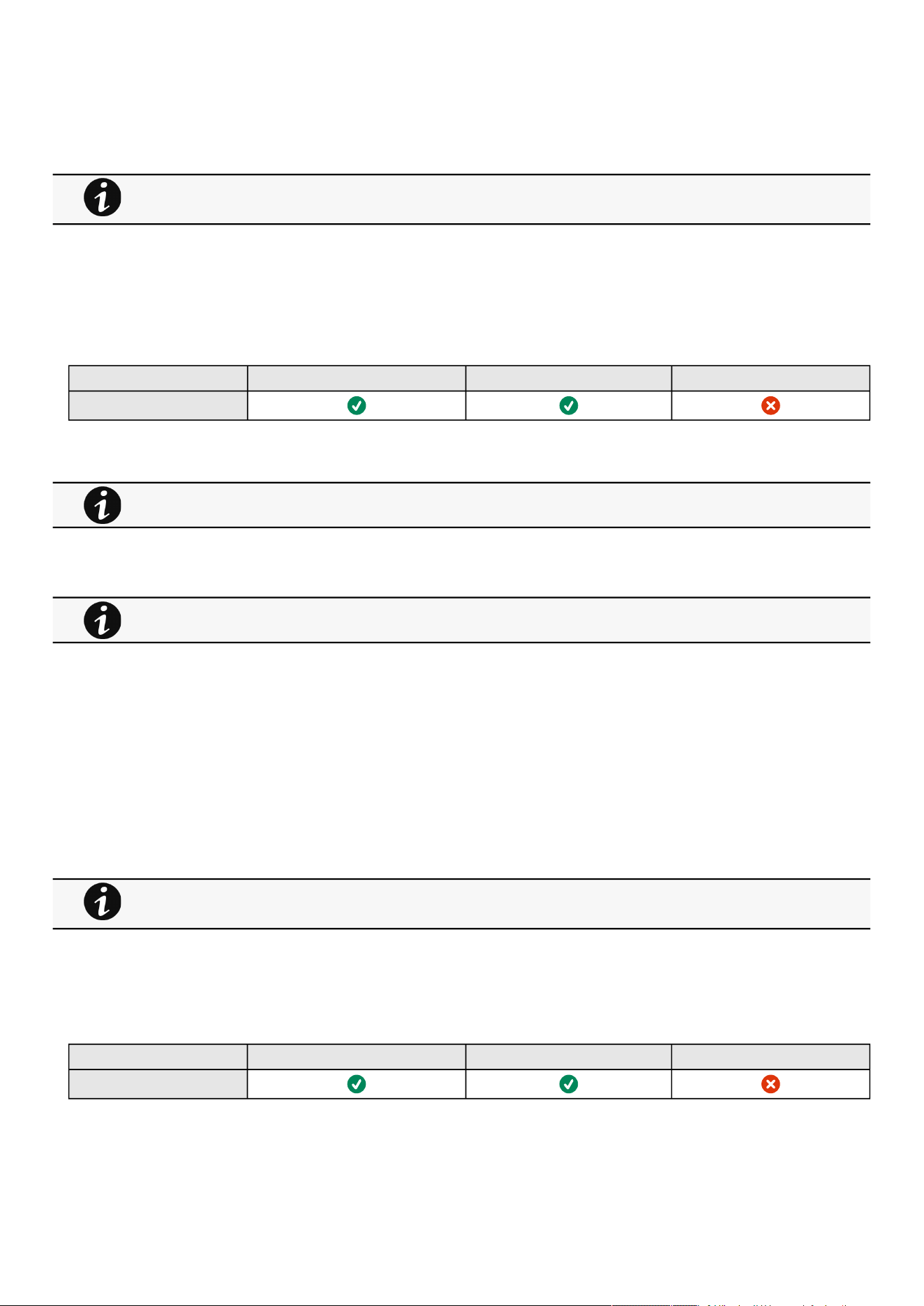
Device details
Contextual help of the web interface – 124
•
•
•
•
•
•
•
•
•
•
Output voltage -To select the output voltage that fits best your need
3.8.2.1 Specifics
3.8.2.2 Access rights per profiles
Administrator Operator Viewer
UPS
3.8.2.2.1 For other access rights
3.8.3 Settings - ATS
Audible alarm -To enable / disable the sound emitted by the UPS when an alarm is triggered ( Battery replacement alarm for
instance or UPS technical fault )
Prefered source – To setthe priority on Source 1 or Source 2 (Source 1 by default).
Sensitivity– To set the sensitivity mode for input mains detection
Normal sensitivity by default
Low sensitivity for compatibility with distorted waveform
High sensitivity when the load demands higher power stability
LIA UPS Input when the power source of the ATS is a Line Interactive UPS
Transfer mode– To set the transfer mode between sources (Standard by default with no additional break even if sources are
no synchronized, Gap with additional break during transfer if sources are not synchronized).
Nominal voltage– To set voltage thresholds.
3.8.3.1 Specifics
3.8.3.2 Access rights per profiles
Administrator Operator Viewer
ATS
Device unique attributes
Some options proposed may not apply to your device. Please refer to the device User Manual Guide.
For other access rights, see the Information>>>Access rights per profiles section.
This section is only for the ATS device and contains all its settings.
Device unique attributes
Some options proposed may not apply to your device. Please refer to the device User Manual Guide.

Maintenance
Contextual help of the web interface – 125
•
•
•
•
•
•
•
3.8.3.2.1 For other access rights
3.9 Maintenance
3.9.1 Firmware
3.9.1.1 Update Network Card Firmware
Monitors the information for the two-embedded firmware.
Upgrade the Network Module firmware.
3.9.1.1.1 Card Firmware information
a Status
Uploading
Invalid
Valid
Pending reboot
Active
b Version/Sha
Displays the associated firmware version and associated Sha.
c Generated on
Displays the release date of the firmware.
For better performance, security, and optimized features,Eatonrecommends to upgrade the Network Module regularly.
d Installation on
Displays when the firmware was installed in the Network Module.
e Activated on
Displays when the firmware was activated in the Network Module.
3.9.1.1.2 Upgrade the Network Module firmware
During the upgrade process, the Network Module does not monitor theDevice status.
To upgrade the firmware:
1.Download the latest firmware version from the website.For more information, see theServicing the Network Management
Module>>>Accessing to the latest Network Module firmware/driver
section.
2. Click+Upload.
3. Click Choose fileand select the firmware package by navigating to the folder where you saved the downloaded firmware.
4. ClickUpload. The upload can take up to 5 minutes.
The firmware that was inactive will be erased by this operation.
For other access rights, see the Information>>>Access rights per profiles section.

Maintenance
Contextual help of the web interface – 126
•
•
•
•
•
•
When an upgrade is in progress, the upload button is disabled, and the progress elements appear below the table with the
following steps:
Transferring > Verifying package > Flashing > Configuring system > Rebooting
A confirmation message displays when the firmware upload is successful, and the Network Module automatically restarts.
3.9.1.2 Update Device Firmware
Unable to render include or excerpt-include. Could not retrieve page.
Upgrade Device Firmware linked to the card.
3.9.1.2.1 Device Firmware information
a Status
Uploading
Invalid
Valid
Pending reboot
Active
b Version/Sha
Displays the associated firmware version and associated Sha.
3.9.1.2.2 Upgrade the Device firmware
During the upgrade process, loads are not protected. Any interruption to input power will result in an interruption of power to
protected loads
To upgrade the device firmware:
1.Download the latest firmware version from the website.For more information, see theServicing the Network Management
Module>>>Accessing to the latest Network Module firmware/driver
section.
2. Click on Upload & Activate button.
3. Select afile and pick the firmware package by navigating to the folder where you saved the downloaded firmware.
4. ClickUpload. The upload can take up to 5 minutes.
The firmware that was inactive will be erased by this operation.
When an upgrade is in progress, the upload button is disabled, and the progress elements appear below the table with the
following steps:
Entering bootloader > Erasing Memory > Programming in progress > Restarting to application mode
A confirmation message displays when the firmware upload is successful.
Do not close the web browser or interrupt the operation.
Depending on your network configuration, the Network Module may restart with a different IP address.
Refresh the browser after the Network module reboot time to get access to the login page.
Press F5 or CTRL+F5 to empty the browser to get all the new features displayed on the Web user interface.
Communication Lost and Communication recovered may appear in the Contextual help>>>Alarms section.
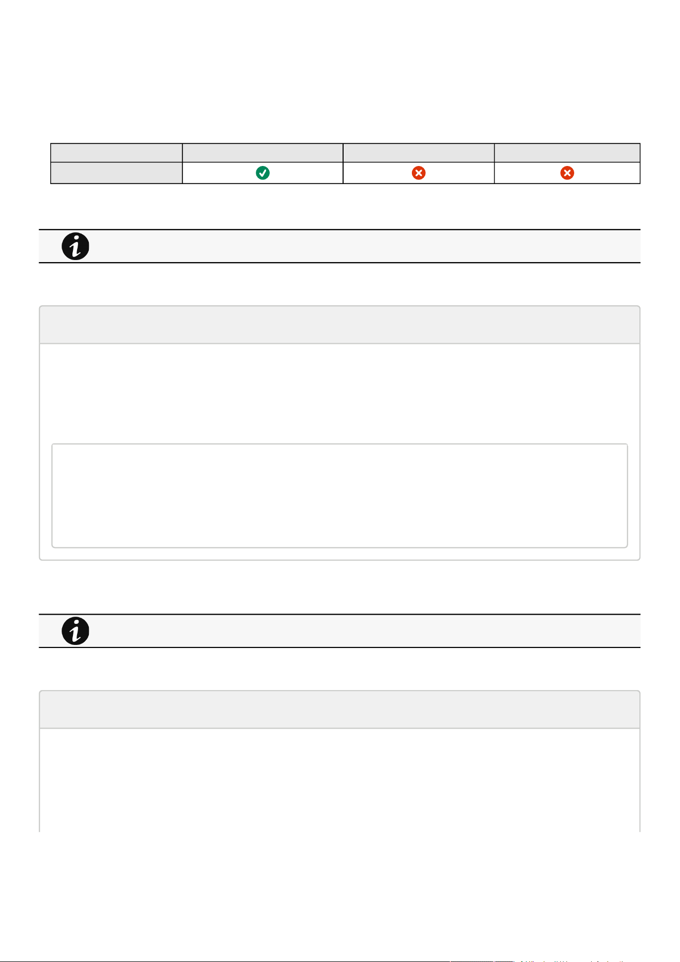
Maintenance
Contextual help of the web interface – 127
3.9.1.3 Specifics
3.9.1.4 Access rights per profiles
Administrator Operator Viewer
Firmware
3.9.1.4.1 For other access rights
3.9.1.5 CLI commands
get release info
Description
Displayscertain basic information related to the firmware release.
Help
get_release_info
-d Get current release date
-s Get current release sha1
-t Get current release time
-v Get current release version number
3.9.1.5.1 For other CLI commands
3.9.1.6 Troubleshooting
The Network Module fails to boot after upgrading the firmware
Possible Cause
1- The IP address has changed.
2- The Network module LED shows solid red after the upgrade.
3- The first boot after the upgrade takes a longer time.
For other access rights, see the Information>>>Access rights per profiles section.
See the CLI commands in the Information>>>CLI section.

Maintenance
Contextual help of the web interface – 128
•
•
•
Note:If theapplication is corrupt, due to an interruptionwhile flashing the firmware for example, the boot will be done on
previous firmware.
Action
1- Recover the IP address and connect to the card.
2- Reset the Network module by using the Restart button on the front panel.
3- Wait until the Network module LED shows flashing green.
Refer to Installing the Network Management Module>>>Accessing the Network Module>>>Finding and setting the IP
address section.
Web user interface is not up to date after a FW upgrade
Symptom
After an upgrade:
The Web interface is not up to date
New features of the new FW are not displayed
An infinite spinner is displayed on a tile
Possible causes
The browser is displaying the Web interface through the cache that contains previous FW data.
Action
Empty the cache of your browser using F5 or CTRL+F5.
3.9.1.6.1 For other issues
3.9.2 Services
3.9.2.1 Service options
3.9.2.1.1 Sanitization
Sanitization removes all the data; the Network Module will come back to factory default settings.
To sanitize the Network Module:
1.ClickSanitize.
A confirmation message displays, click Sanitize to confirm.
For details on other issues, see the Troubleshooting section.
For details on default settings, see theInformation>>>Default settings parameterssection.

Maintenance
Contextual help of the web interface – 129
3.9.2.1.2 Reboot
Reboot means restarting the network module operating system.
To reboot the Network Module:
ClickReboot.
A confirmation message displays, clickRebootto confirm, the reboot time will take approximately less than 2min.
3.9.2.1.3 Settings
Allow to save and restore the Network module settings.
3.9.2.1.4 Save
To save the Network module settings:
1.Click onSave
2. Select to include the Network settings if needed.
A passphrase need to be entered twice to cypherthe sensitive data.
3. Click onSave
3.9.2.1.5 Restore
To restore the Network module settings:
1.Click onRestore
2. Select to include the Network settings if needed.
3.Enter the passphrase used when the file was saved.
4. Click on Choose file andselect the JSON file
5. Click onRestoreto confirm
6. For safety reason, re-enter your own password to confirm your idendity
3.9.2.1.6 Maintenance
The maintenance report is for the service representative use to diagnose problems with the network module. It is not intended for
the user, which is why the file is protected by a password.
Depending on your network configuration, the Network Module may restart with a different IP address.
Only main administrator user will remain with default login and password.
Refresh the browser after the Network module reboot time to get access to the login page.
Depending on your network configuration, the Network Module may restart with a different IP address.
Refresh the browser after the Network module reboot time to get access to the login page.
Communication Lost and Communication recovered may appear in the Alarm section.
For more details, navigate to Servicing the Network Management Module>>>Saving/Restoring/Duplicating section.
Below settings are not saved:
Local users other than the main administratorSensor settings (commissioning, alarm configuration)
Restoring settings may result in the Network module reboot.
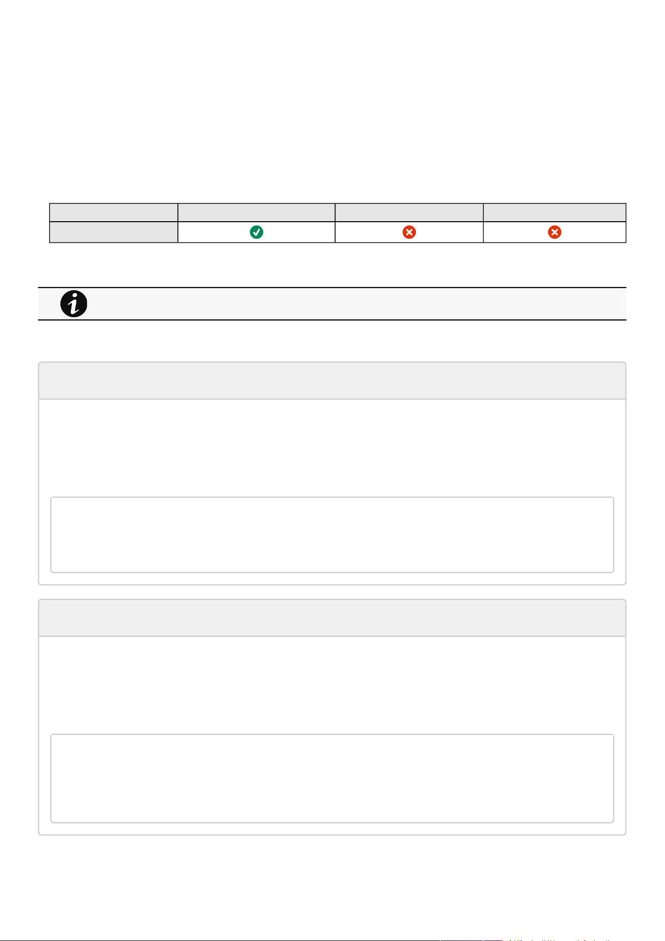
Maintenance
Contextual help of the web interface – 130
To download the maintenance report file:
ClickDownload report.
A confirmation message displays,Maintenance report file successfully downloaded.
3.9.2.2 Specifics
3.9.2.3 Access rights per profiles
Administrator Operator Viewer
Services
3.9.2.3.1 For other access rights
3.9.2.4 CLI commands
maintenance
Description
Creates a maintenance report file whichmaybehandedto the technical support.
Help
maintenance
<cr> Create maintenance report file.
-h, --help Display help page
reboot
Description
Tool to Reboot the card.
Help
Usage: reboot [OPTION]
<cr> Reboot the card
--help Display help
--withoutconfirmation Reboot the card without confirmation
For other access rights, see the Information>>>Access rights per profiles section.

Maintenance
Contextual help of the web interface – 131
•
•
•
•
•
•
save_configuration | restore_configuration
Description
Save_configuration and restore_configuration are using JSON format to save and restorecertain part of the configuration of
the card.
Help
save_configuration -h
save_configuration: print the card configuration in JSON format to standard output.
restore_configuration -h
restore_configuration: restore the card configuration from a JSON-formatted standard
input.
Examples of usage
From a linux host:
Save over SSH:sshpass -p $PASSWORD ssh $USER@$CARD_ADDRESS save_configuration -p $PASSPHRASE> $FILE
Restore over SSH:cat $FILE | sshpass -p $PASSWORD ssh $USER@$CARD_ADDRESS restore_configuration -p
$PASSPHRASE
From a Windows host:
Save over SSH:plink $USER@$CARD_ADDRESS -pw$PASSWORD -batch save_configuration -p $PASSPHRASE > $FILE
Restore over SSH:type $FILE | plink $USER@$CARD_ADDRESS -pw $PASSWORD -batch restore_configuration -p
$PASSPHRASE
(Require plink tools from putty)
Where:
$USER is user name (the user shall have administrator profile)
$PASSWORD is the user password
$PASSPHRASE is any passphrase to encrypt/decrypt sensible data.
$CARD_ADDRESS is IP or hostname of the card
$FILE is a path to the JSON file (on your host computer) where the configuration is saved or restored.
sanitize
Description
Sanitize command to return card to factory reset configuration.
Access
Administrator
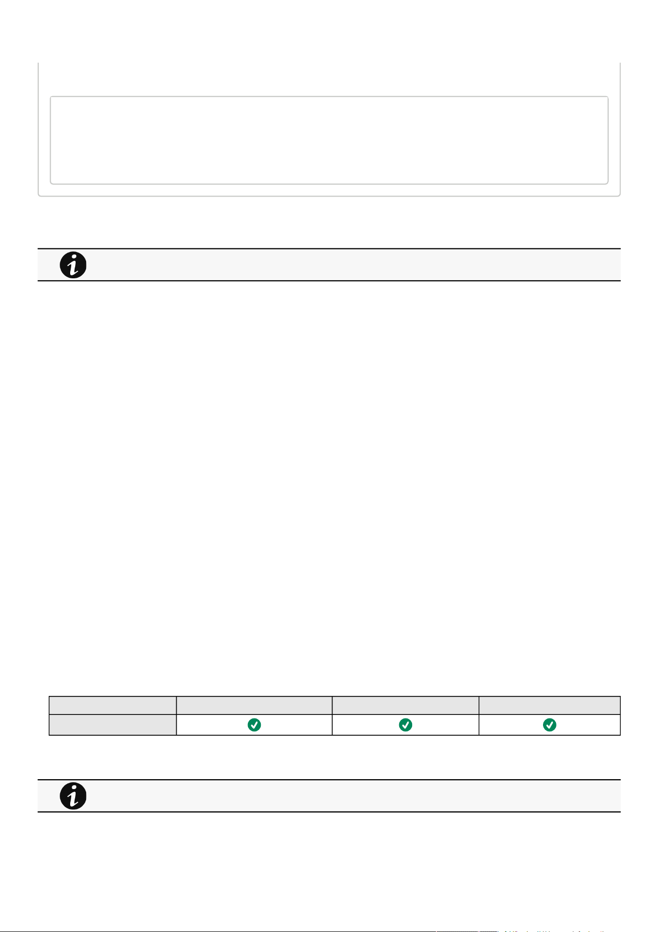
Maintenance
Contextual help of the web interface – 132
•
•
•
•
•
•
•
•
•
Help
sanitize
-h, --help Display help page
--withoutconfirmation Do factory reset of the card without confirmation
<cr> Do factory reset of the card
3.9.2.4.1 For other CLI commands
3.9.3 Resources
Card resources is an overviewof the Network Module processor, memory and storage information.
TheCOPY TO CLIPBOARDbutton will copy the information toyour clipboard so that it can be past.
For example, you can copy and paste information into an email.
3.9.3.1 Processor
Used in %
Up since date
3.9.3.2 Memory
Total size in MB
Available size in MB
Application size in MB
Temporary files size in MB
3.9.3.3 Storage
Total size in MB
Available size in MB
Used size in MB
3.9.3.4 Specifics
3.9.3.5 Access rights per profiles
Administrator Operator Viewer
Resources
3.9.3.5.1 For other access rights
See the CLI commands in the Information>>>CLI section.
For other access rights, see the Information>>>Access rights per profiles section.
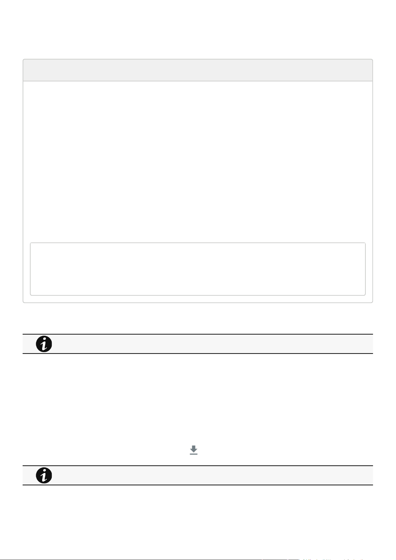
Maintenance
Contextual help of the web interface – 133
1.
a.
b.
2.
a.
b.
c.
d.
3.
a.
i.
ii.
iii.
•
•
•
•
3.9.3.6 CLI commands
systeminfo_statistics
Description
Displays the following system information usage:
CPU
usage : %
upSince: date since the system started
Ram
total: MB
free: MB
used: MB
tmpfs: temporary files usage (MB)
Flash
user data
total: MB
free: MB
used: MB
Help
systeminfo_statistics
Display systeminfo statistics
-h, --help Display the help page.
3.9.3.6.1 For other CLI commands
3.9.4 System logs
3.9.4.1 System logs
There are 4 types of logs available:
Update
Account
Session
System
Select the log files to download and press the download icon:
See the CLI commands in the Information>>>CLI section.
For the list of system logs, see the Information>>>System Logs codes section.
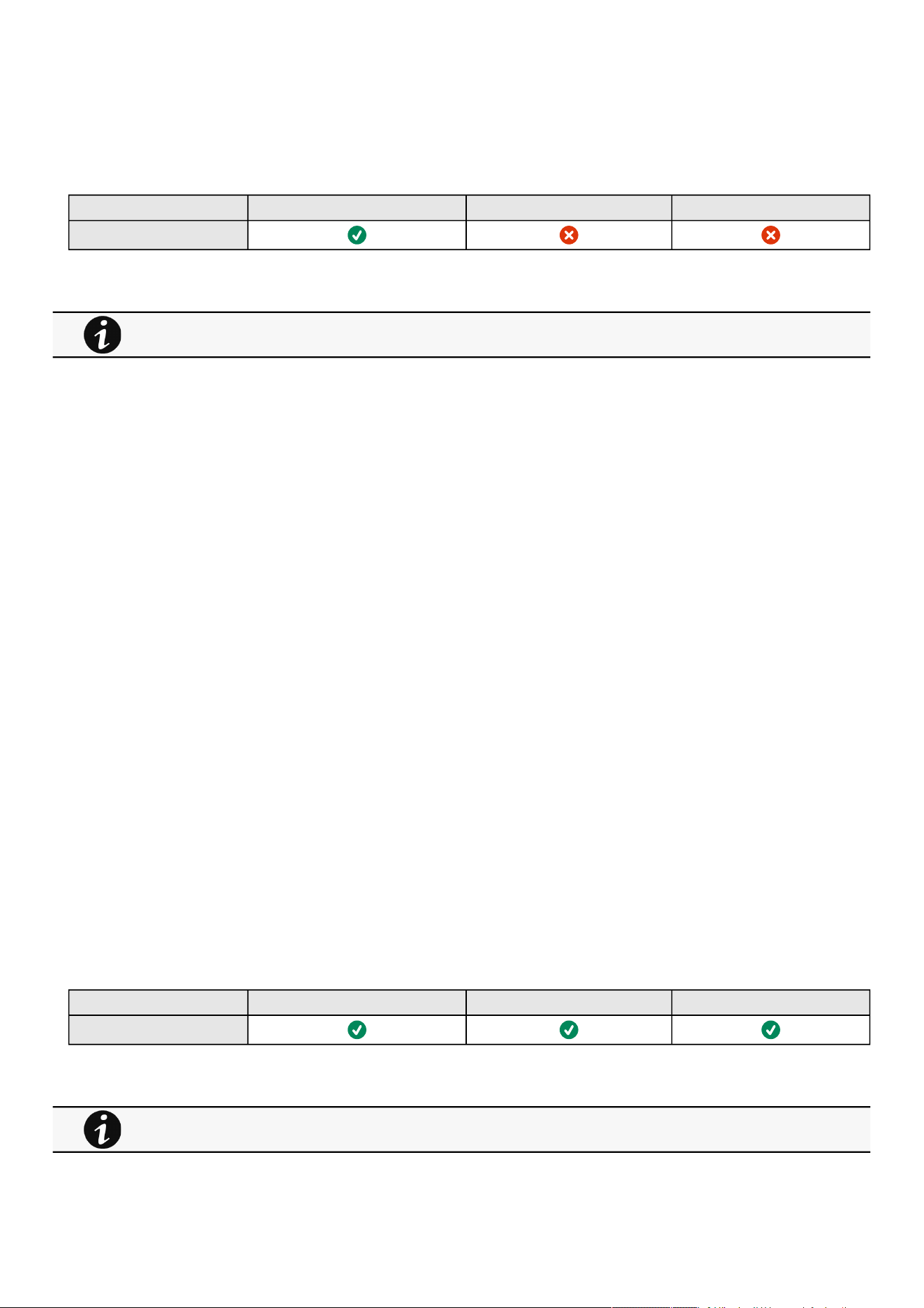
Maintenance
Contextual help of the web interface – 134
•
•
•
•
•
•
•
•
•
•
•
•
•
•
•
•
•
3.9.4.2 Specifics
3.9.4.3 Access rights per profiles
Administrator Operator Viewer
System logs
3.9.4.3.1 For other access rights
3.9.5 System information
System information is an overviewof the main Network Module information.
The COPY TO CLIPBOARD button will copy the information to the clipboard.
3.9.5.1 Identification
System name– if filled, it replaces the Device model name in the top bar
Product
Physical name
Vendor
UUID
Part number
Serial number
Hardware version
Location
Contact
MAC address
3.9.5.2 Firmware information
Version
SHA
Build date
Installation date
Activation date
Bootloader version
3.9.5.3 Specifics
3.9.5.4 Access rights per profiles
Administrator Operator Viewer
System information
3.9.5.4.1 For other access rights
For other access rights, see the Information>>>Access rights per profiles section.
For other access rights, see the Information>>>Access rights per profiles section.

Alarms
Contextual help of the web interface – 135
•
•
•
•
•
•
•
•
3.10 Alarms
3.10.1 Alarm sorting
Alarms can be sorted by selecting:
All
Active only
3.10.2 Active alarm counter
3.10.3 Alarm details
Allalarms are displayed andsorted by date, with alert level, time, description, and status.
Info/Warning/Critical logo Alarm description text
Active In color In bold with "Active" label
Opened In color
Closed Greyed
3.10.4 Alarm paging
The number of alarms per page can be changed (10-15-25-50-100).
When the number of alarms is above the number of alarms per page,the buttons First, Previous andNextappears to allow
navigation in the Alarm list.
3.10.5 Export
Press theExportbutton to download the file.
3.10.6 Clear
Press theClearbutton to clear alarms that are older than a specified date and up to a defined severity.
3.10.7 Specifics
3.10.8 Alarms list with codes
To get access to the Alarm log codes or the System log codes for email subscription, seesections below:
System log codes
UPS(HID) alarm log codes
UPS(XCP and COPI) alarm log codes
ATS alarm log codes
EMP alarm log codes
Network module alarm log codes
Alarms with a severity set as Good are not taken into account into the counter of active alarms.
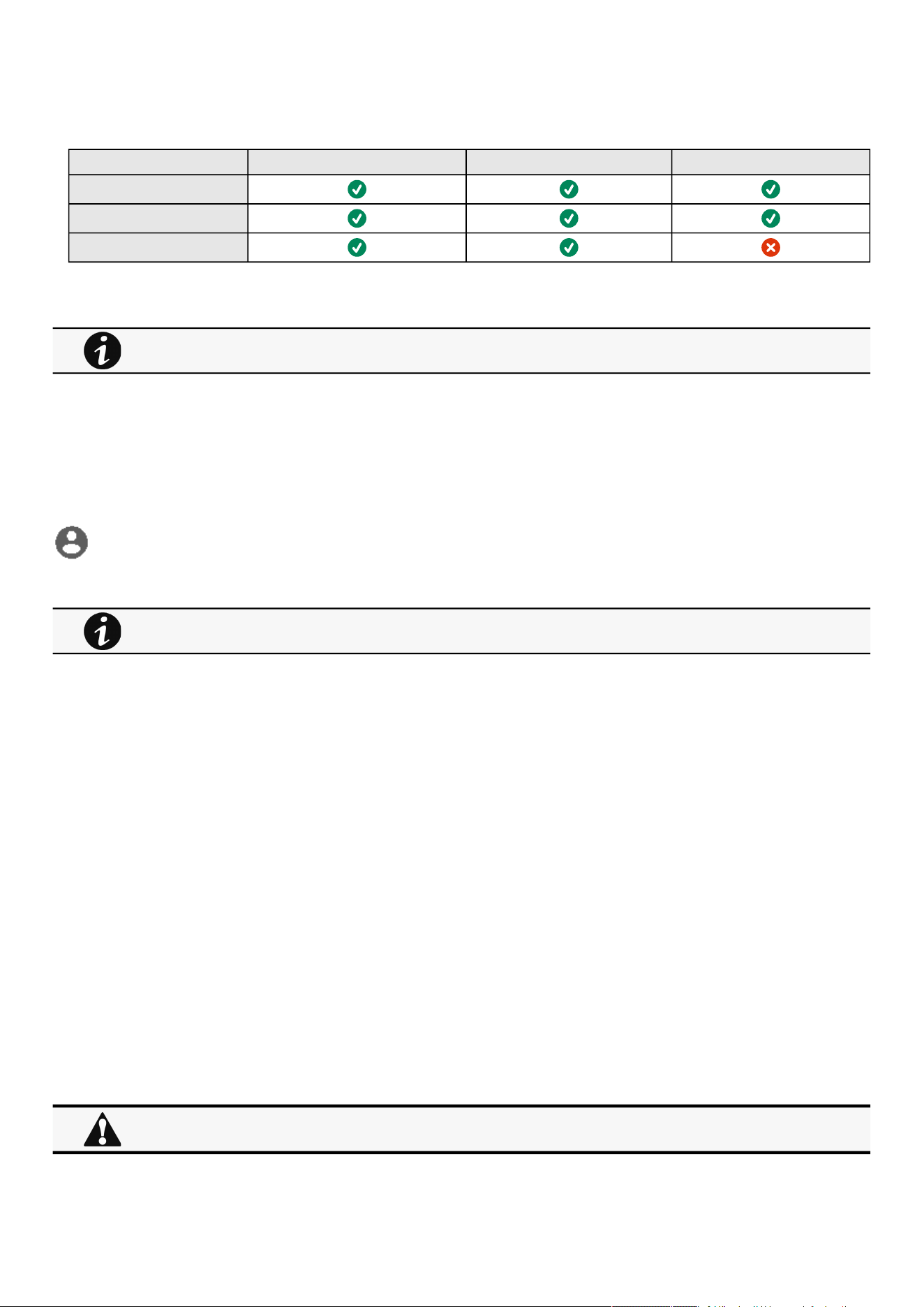
User profile
Contextual help of the web interface – 136
•
•
•
•
•
•
•
•
3.10.9 Access rights per profiles
Administrator Operator Viewer
Alarm list
Export
Clear
3.10.9.1 For other access rights
3.11 User profile
3.11.1 Access to the user profile
Press theicon on the top right side of the page to access the user profile window:
3.11.2 User profile
This page displays the current username with its realm (local, remote) and allows to Change passwords, Edit account and Log out.
3.11.2.1 Account settings
If you have the administrator's rights, you can click on Edit accounttoedit user profile and update the following information:
Account details
Full name
Email
Phone
Organization
Preferences
Language
Date format
Time format
Temperature
3.11.2.2 Change password
Click onChange passwordto change the password.
For other access rights, see the Information>>>Access rights per profiles section.
This page is in read-only mode when connected through LDAP and it displays the preferences applied to all LDAP
users as configured in the Contextual help>>>Settings>>>Remote users>>>LDAP section.
In some cases, it is not possible to change the password if it has already been changed within a day period.
Refer to the troubleshooting section.

User profile
Contextual help of the web interface – 137
•
•
•
•
•
•
•
•
•
•
•
•
•
•
•
•
3.11.2.3 Log out
Click Log outto close the session.
3.11.3 Legal information
This Network Module includes software components that are either licensed under various open source license, or under a
proprietary license.
3.11.4 Component
All the open source components included in the Network Module are listed with their licenses.
3.11.5 Availability of source code
Provides the way to obtain the source code of open source components that are made available by their licensors.
3.11.6 Notice for proprietary elements
Provides notice for our proprietary (i.e. non-Open source) elements.
3.11.7 Specifics
3.11.8 Default settings and possible parameters - User profile
Default setting Possible parameters
Profile Account details:
Full name — Administrator
Email — blank
Phone — blank
Organization — blank
Preferences:
Language — English
Date format — MM-DD-YYYY
Time format — hh:mm:ss (24h)
Temperature — °C (Celsius)
Account details:
Full name — 128 characters maximum
Email — 128 characters maximum
Phone — 64 characters maximum
Organization — 128 characters maximum
Preferences:
Language — English, French, German,
Italian, Japanese, Russian, Simplified
Chinese, Spanish, Traditional Chinese
Date format — MM-DD-YYYY / YYY-MM-
DD / DD-MM-YYY / DD.MM.YYY / DD/MM/
YYY / DD MM YYYY
Time format — hh:mm:ss (24h) / hh:mm:ss
(12h)
Temperature — °C (Celsius)/°F (Fahrenheit)
3.11.8.1 For other settings
3.11.9 Access rights per profiles
Administrator Operator Viewer
User profile
For other settings, see the Information>>>Default settings parameters section.
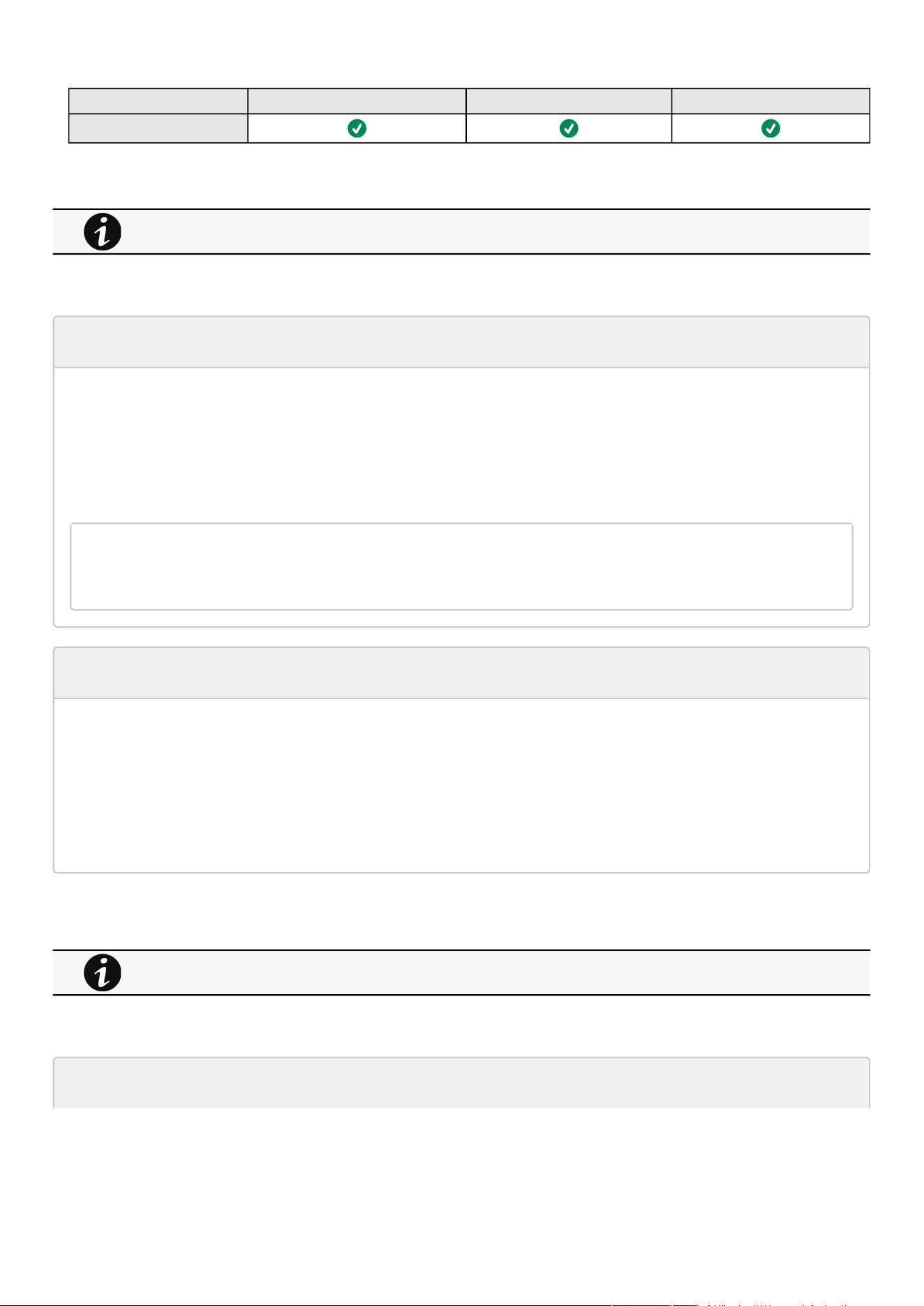
User profile
Contextual help of the web interface – 138
•
•
•
Administrator Operator Viewer
Legal information
3.11.9.1 For other access rights
3.11.10 CLI commands
logout
Description
Logout the current user.
Help
logout
<cr> logout the user
whoami
Description
whoami displays current user information:
Username
Profile
Realm
3.11.10.1 For other CLI commands
3.11.11 Troubleshooting
Password change in My profile is not working
For other access rights, see the Information>>>Access rights per profiles section.
See the CLI commands in the Information>>>CLI section.

User profile
Contextual help of the web interface – 139
Symptoms
The password change shows "
Invalid credentials
" when I try to change my password in My profile menu:
Possible cause
The password has already been changed once within a day period.
Action
Let one day between your last password change and retry.
3.11.11.1 For other issues
3.11.12 Save and Restore
SRR section Settings Possible values
Account details vCard fullName String: refer to default settings an possible
parameters for constraints.
email String: refer to default settings an possible
parameters for constraints.
phone String: refer to default settings an possible
parameters for constraints.
organization String: refer to default settings an possible
parameters for constraints.
Preferences preferences notifyByMail true/false
licenseAgreed true/false
language de: Deutsch
en: English
es: Español
fr: Français
it: Italiano
ja: 日本語
ru: русский
zh_Hans: 简体中文
zh_Hant:繁體中文
For details on other issues, see the Troubleshooting section.
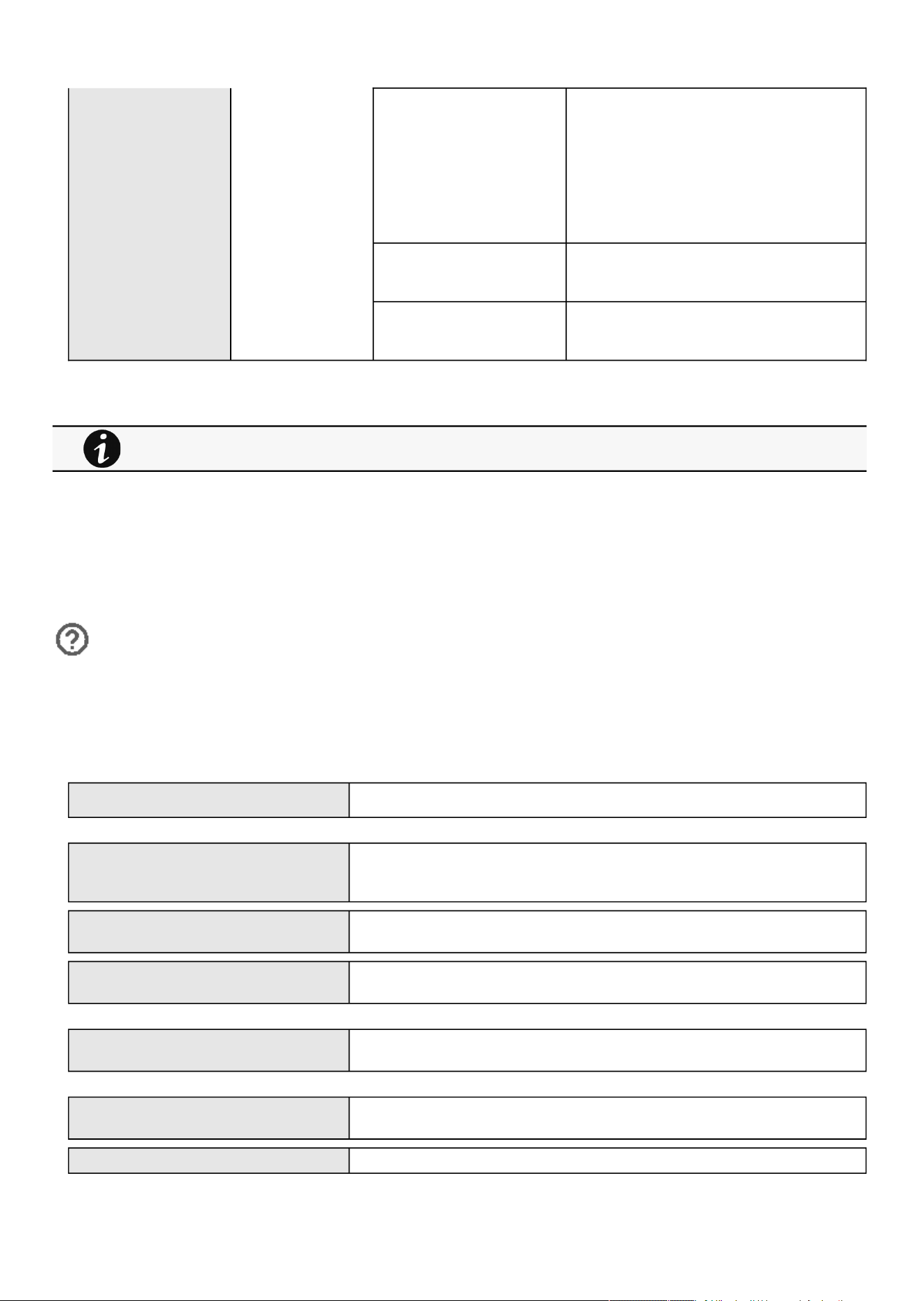
Documentation
Contextual help of the web interface – 140
dateFormat Y-m-d: YYYY-MM-DD
d-m-Y: DD-MM-YYYY
d.m.Y: DD.MM.YYYY
d/m/Y: DD/MM/YYYY
m/d/Y: MM/DD/YYYY
d m Y: DD MM YYYY
timeFormat 1: 24h
0: 12h
temperatureUnit 1: °C
2: °F
3.11.12.1 Additional information
3.12 Documentation
3.12.1 Access to the embedded documentation
Press the ?icon on the top right side of the page to access the documentationin a new window:
The focus will be made on the contextual page.
You can then navigate into below sections:
Installing the Network Management Module How to install and access the Network module.
Contextual help of the web interface Help for each webpage.
Extracts from the sections below when they are related to the web page.
Servicing the Network Management Module How to install and use the Network module.
Securing the Network Management Module How to secure the Network module.
Servicing the EMP Information on the EMP, how to install and use it.
Information General information of the Network Module and Devices.
Troubleshooting How to troubleshoot the Network Module.
For details on Save and Restore, see the Save and Restore section.
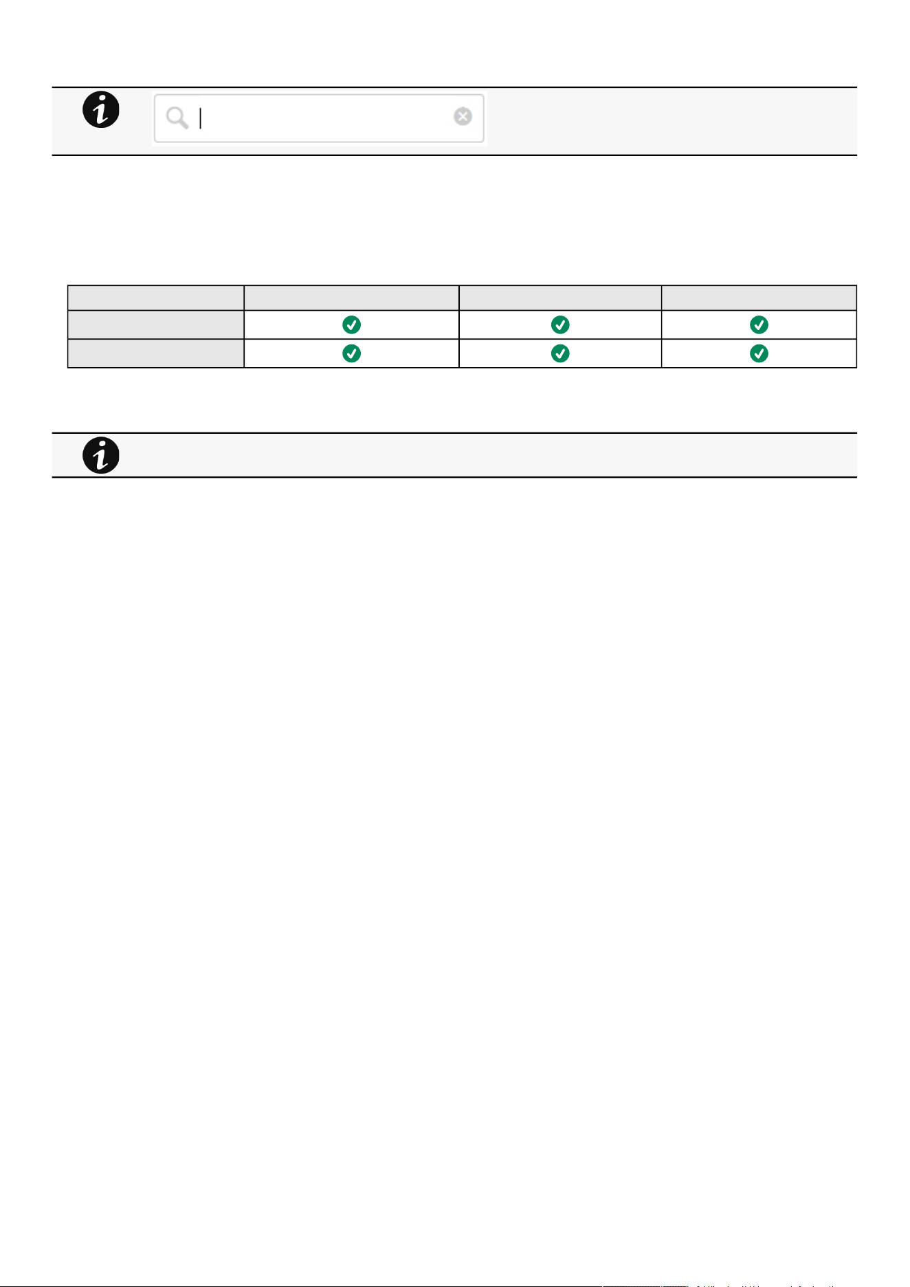
Documentation
Contextual help of the web interface – 141
3.12.2 Specifics
3.12.3 Access rights per profiles
Administrator Operator Viewer
Contextual help
Full documentation
3.12.3.1 For other access rights
Search feature is indexed.
For other access rights, see the Information>>>Access rights per profiles section.

Configuring/Commissioning/Testing LDAP
Servicing the Network Management Module – 142
1.
2.
3.
4.
a.
b.
5.
6.
7.
1.
2.
3.
4 Servicing the Network Management Module
4.1 Configuring/Commissioning/Testing LDAP
4.1.1 Commissioning
Refer to the sectionContextual help>>>Settings>>>Local users to get help on the configuration.
4.1.1.1 Configuring connection to LDAP database
This step configures the LDAP client of the network module to request data from an LDAP base.
Activate LDAP.
Define security parameters according to LDAP servers' requirements.
Configure primary server (and optionally a secondary one).
If security configuration needs server certificate verification, import your LDAP server certificate.
Refer to the section to get help on certificate import.
In case LDAP server certificate is self-signed, import the self-signed certificate in the
Trusted remote certificate
list
for
LDAP
service.
in case LDAP server certificate has been signed by a CA, import the corresponding CA in the
Certificate authorities
(CA)
list for
LDAP
service.
Configure credentials to bind with the LDAP server or select
anonymous
if no credentials are required.
Configure the
Search base DN
.
Configure the request parameters (see examples below).
4.1.1.1.1 Typical request parameters
Parameter OpenLDAP Active Directory™ with POSIX
account activated
Active Directory™
User base DN ou=users, dc=example, dc=com ou=users, dc=example, dc=com ou=users, dc=example, dc=com
User name attribute uid uid sAMAccountName
UID attribute uidNumber uidNumber objectSid:S-1-5-xx-yy-zz (domain SID)
Group base DN ou=groups, dc=example, dc=com ou=groups, dc=example, dc=com ou=groups, dc=example, dc=com
Group name attribute gid gid sAMAccountName
GID attribute gidNumber gidNumber objectSid:S-1-5-xx-yy-zz (domain SID)
4.1.1.2 Testing connection to LDAP database
Refer to the sectionInformation>>>CLI>>>ldap-testto get help on the CLI command.
To test connection to the LDAP database:
Connect to the CLI.
Launch
ldap-test --checkusername
command.
In case of error, use the
verbose
option ofthe command to investigate the reason.
4.1.1.3 Map remote users to profile
This step is mandatory and configures the Network module to give permissions to the LDAP users.
Users not belonging to a group mapped on a profile will be rejected.

Pairing agent to the Network Module
Servicing the Network Management Module – 143
1.
2.
1.
2.
3.
4.
1.
2.
3.
4.
•
•
•
•
•
•
•
Configure the rules to mapped LDAP users to profile:
Enter LDAP group name.
Select the profile to assigned.
You can define up to 5 mapping rules.
All LDAP users belonging to the configured LDAP group will have permissions granted by the associated profile.
4.1.1.4 Testing profile mapping
Refer to the sectionInformation>>>CLI>>>ldap-testto get help on the CLI command.
To test LDAP users profile mapping:
Connect to the CLI.
Launch
ldap-test --checkmappedgroups
command.
This command will verify each mapped group exists in the LDAP base and will display the associated local profile.
In case of error, use the
verbose
option ofthe command to investigate the reason.
4.1.1.5 Define LDAP user's preferences
This step configures the user's preferences to apply to all LDAP users.
4.1.2 Testing LDAP authentication
Refer to the sectionInformation>>>CLI>>>ldap-testto get help on the CLI command.
Connect to the CLI.
Launch
ldap-test --checkauth
command.
This command will verify an LDAP user can authenticate using his username and password and will display its local profile.
In case of error, use the
verbose
option ofthe command to investigate the reason
4.1.3 Limitations
If the same username exists in both local and LDAP databases, the behavior is undefined.
If a user belongs to multiple LDAP groups mapped to different profiles, the behavior is undefined.
No client certificate provided. It is not possible for the server to verify the client authenticity.
It is not possible to configure LDAP to work with 2 different search bases.
LDAP user's preferences are common to all LDAP users.
LDAP users cannot change their password through the Network Module.
The remote groupname entered in profile mapping settings must be composed only of alphanumerics, underscore and
hyphen characters (but this last one can't be at the beginning).
4.2 Pairing agent to the Network Module
Authentication and encryption of connections between the UPS network module and shutdown agents is based on matching
certificates.
4.2.1 Pairing with credentials on the agent
STEP 1: Action on the agent (IPP/IPM).
1. Connect to the web interface of the agent.
2. Detect the UPS Network Module with an Address(es) scan, select Override global authentication settings and type the UPS
Network Module credentials.
If a user belongs to multiple LDAP groups mapped to different profiles, the behavior is undefined.

Pairing agent to the Network Module
Servicing the Network Management Module – 144
•
•
•
•
•
•
•
•
•
•
4.2.2 Pairing with automatic acceptance (recommended if done in a
secure and trusted network)
Pairing with automatic acceptance of shutdown agents and UPS network modules is recommended in case the installation is done
in a secure and trusted network, and when certificates cannot be created in other ways.
STEP 1: Action on the Network Module
1.Connect to the Network Module
On a network computer, launch a supported web browser. The browser window appears.
In the Address/Location field, enter: https://xxx.xxx.xxx.xxx where xxx.xxx.xxx.xxx is the static IP address of the Network
Module.
The log in screen appears.
Enter the user name in the User Name field.
Enter the password in the Password field.
Click Login. The Network Module web interface appears.
2. Navigate to Contextual help>>>Protection>>>Agents list page
3. In the Pairing with shutdown agentssection, select the time to accept new agents and press the Start button and the
pressContinue. During the selected timeframe, new agent connections to the Network Module are automatically trusted and
accepted.
STEP 2: Action on the agent (IPP) while the time to accepts new agents is running on the Network Module
1. Connect to the web interface of the agent.
2. Detect the UPS Network Module with a Quick scan, Range scan or an Address(es) scan.
3. Right-click on the UPS Network Module when discovered and then Set aspower source,Configure it, andSave it.
STEP 3: Action on the Network Module
1. Make sure all listed agents in the card (Contextual help>>>Protection>>>Agents list) belong to your infrastructure, if not,
access may be revoked using theDeletebutton.
2. If the time for pairing still runs, you can stop it. Press Stop in thePairing with shutdown agentssection.
4.2.3 Pairing with manual acceptance
Manual pairing provides the maximum security.
STEP 1: Action on the agent (IPP)
1. Connect to the web interface of the agent
2. Detect the UPS Network Module with a Quick scan, Range scan or an Address(es) scan.
3. Define the power source
Note: After that stage, the agent creates a client certificate. The power source could show a communication loss since the
current client certificate is not trusted by the Network Module.
4.Copy the agent certificate file client.pemthat is located in the folderEaton\IntelligentPowerProtector\configs\tls..
STEP 2: Action on the Network Module
1.Connect to the Network Module
On a network computer, launch a supported web browser. The browser window appears.
In the Address/Location field, enter: https://xxx.xxx.xxx.xxx where xxx.xxx.xxx.xxx is the static IP address of the Network
Module.
The log in screen appears.
Enter the user name in the User Name field.
STEP 1 and STEP2 can be done either ways.
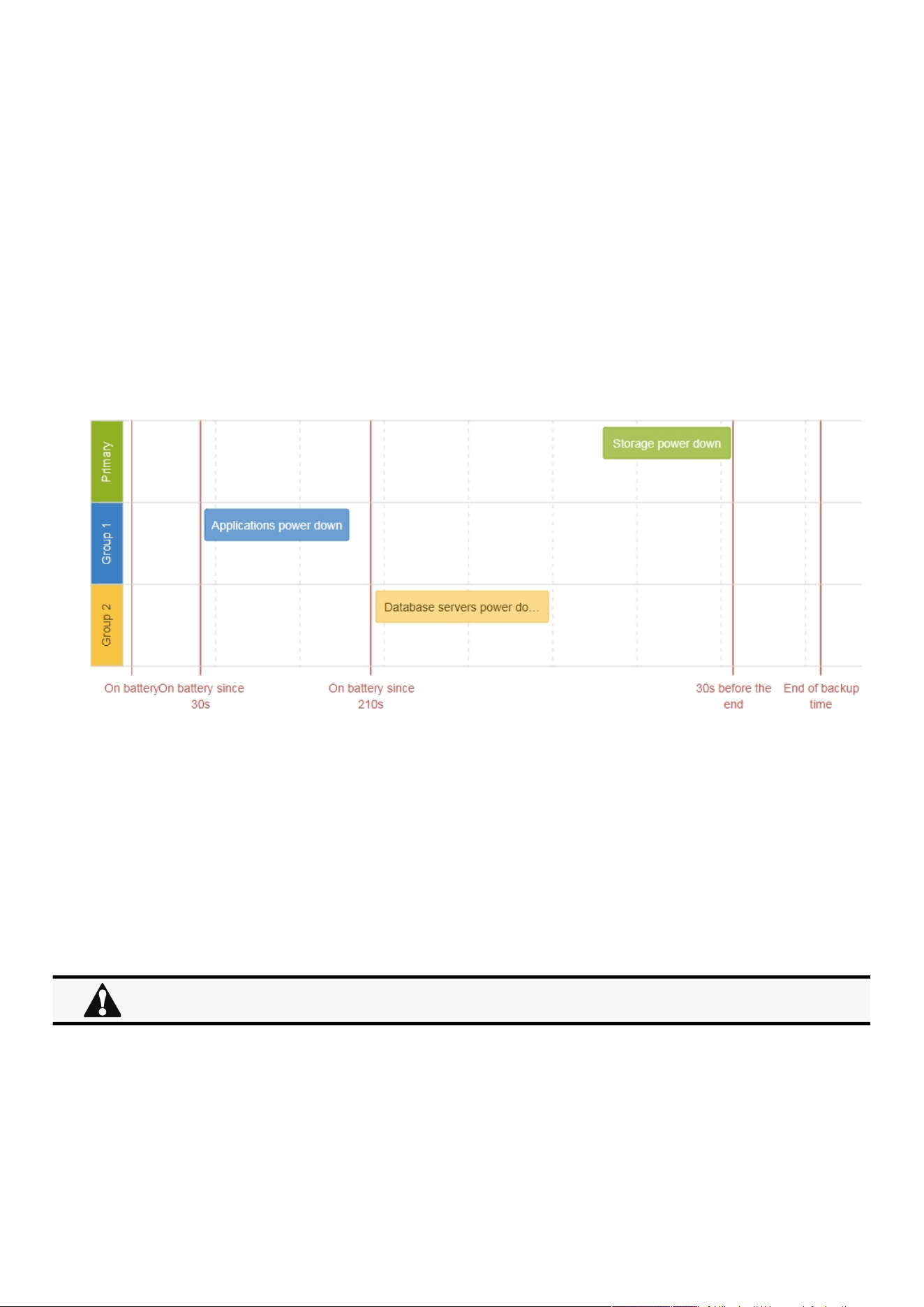
Powering down/up applications (examples)
Servicing the Network Management Module – 145
•
•
•
•
•
Enter the password in the Password field.
Click Login. The Network Module web interface appears.
2. Navigate to Contextual help>>>Settings>>>Certificatepage
3. In theTrusted remote certificates section, click Import, selectProtected applications (MQTT) and thenclick on CONTINUE
4. Select the client.pem file previously saved, click Open. Communication with the agent is restored.
4.3 Powering down/up applications (examples)
4.3.1 Powering down IT system in a specific order
4.3.1.1 Target
Powering down applications first (when on battery for 30s), database servers next (3min after the applications), and storage last (as
late as possible).
4.3.1.2 Step 1: Installation setup
4.3.1.2.1 Objective
Use load segmentation provided by the UPS to independently control the power supply of each IT equipment categories
(Applications, Database servers, Storage).
It also allows IT equipment to sequentially restart on utility recovery (Restart sequentially the IT equipment on utility recovery).
4.3.1.2.2 Resulting setup
UPS provides outlets (Group 1 and Group 2) and a primary output.
Connections to UPS are done as described below:
Group 1: Applications
Group 2: Database servers
Primary: Storage
When primary shuts OFF, both group 1 and group 2 shut OFF immediately.

Powering down/up applications (examples)
Servicing the Network Management Module – 146
•
•
•
4.3.1.3 Step 2: Agent settings
4.3.1.3.1 Objective
Ensure IT solution is shutdown gracefully.
4.3.1.3.2 Resulting setup
1. InstallIPPSoftware on each server (Application, Database servers, Storage) and register the UPS load segment as power source:
Applications:Group 1
Database servers:Group 2
Storage: Entire UPS
2. Pair agent to the Network Module (Pairing agent to the Network Module).
When done, each server appears in the Agent list.
3.Navigate toContextual help>>>Protection>>>Agent shutdown sequencingpage.
4. Set the OS shutdown duration to the time needed for your server to shutdown gracefully.
This will make sureIPPshutdowns your servers before the load segment is powered down.
As a result, it will define the overall shutdown sequence duration for each load segments.
4.3.1.4 Step 3: Power outage policy settings
4.3.1.4.1 Objective
Use load segment policies to define shutdown sequencing.
4.3.1.4.2 Resulting setup
1. Navigate toContextual help>>>Protection>>>Shutdown on power outagepage of the Network Module
2. Make sure Primary is set to: Maximize availability.
For examples of Agent settings, see the Agent shutdown sequencing examples section.
•
•
•
•
For examples of Power outage policy, see the following sections:
Maximize availability policy example
Immediate graceful shutdown policy example
Load shedding policy examples
Custom policy examples
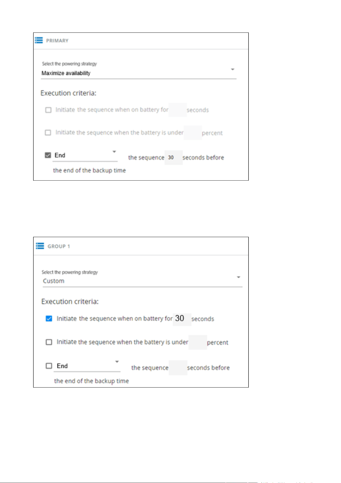
Powering down/up applications (examples)
Servicing the Network Management Module – 147
Storage is the last one to power down, its availability is maximized, and its shutdown will end 30s before the end of backup
time.
3. Set Group 1 and Group 2 to: Custom.
Applications must shutdown first so Group 1 has been set to start shutdown when on battery for 30s.
Servers must shutdown second, so Group 2has been set to start shutdown when on battery for 210s, so 3min after the
applications.
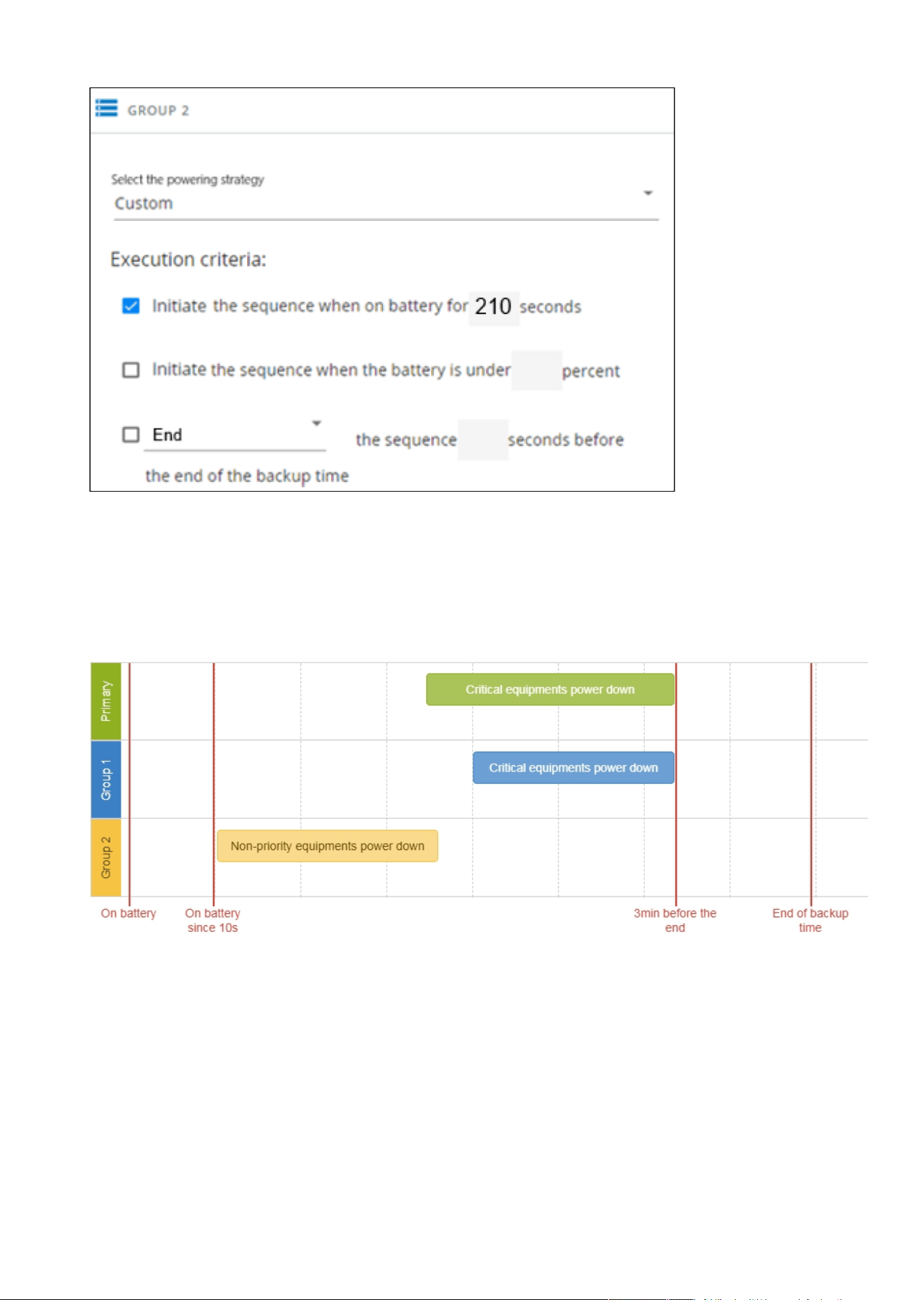
Powering down/up applications (examples)
Servicing the Network Management Module – 148
4.3.2 Powering down non-priority equipment first
4.3.2.1 Target
Powering down non-priority equipment first (immediately) and keep battery power for critical equipment.
Powering down critical equipment 3min before the end of backup time.
4.3.2.2 Step 1: Installation setup
4.3.2.2.1 Objective
Use load segmentation provided by the UPS to independently control the power supply of each IT equipment categories
(Applications, Database servers, Storage).
Load segmentation also allows IT equipment to restart sequentially on utility recovery(Restart sequentially the IT equipment on
utility recovery).

Powering down/up applications (examples)
Servicing the Network Management Module – 149
•
•
•
•
•
•
4.3.2.2.2 Resulting setup
UPS provides outlets (Group 1 and Group 2) and a primary output.
Connections can be done as described below:
Group 2: non-priority equipment
Group 1: critical equipment
Primary:criticalequipment
4.3.2.3 Step 2: Agent settings
4.3.2.3.1 Objective
Ensure IT solution is shutdown gracefully.
4.3.2.3.2 Resulting setup
1. InstallIPPSoftware on each server (Application, Database servers, Storage) and register the UPS load segment as power source:
Critical equipment:Group 1
Non-priority equipment:Group 2
Critical equipment: Entire UPS
2. Pair agent to the Network Module (Pairing agent to the Network Module).
When done, each server appears in the Agent list.
3.Navigate toContextual help>>>Protection>>>Agent shutdown sequencingpage
4. Set the OS shutdown duration to the time needed for your server to shutdown gracefully.
This will make sureIPPshutdowns your servers before the load segment is powered down.
As a result, it will define the overall shutdown sequence duration for each load segments.
4.3.2.4 Step 3: Power outage policy settings
4.3.2.4.1 Objective
Use load segment policies to define shutdown sequencing.
4.3.2.4.2 Resulting setup
1. Navigate toContextual help>>>Protection>>>Shutdown on power outagepage on the Network Module
2. Set Primary and Group 1 to:Customand set it to end shutdown sequence 180s before the end of backup time.
When primary shuts OFF, both group 1 and group 2 shut OFF immediately.
For examples of Agent settings, see the Agents shutdown sequencing sections.
•
•
•
•
For examples of Power outage policy, see the following sections:
Maximize availability policy example
Immediate graceful shutdown policy example
Load shedding policy examples
Custom policy examples
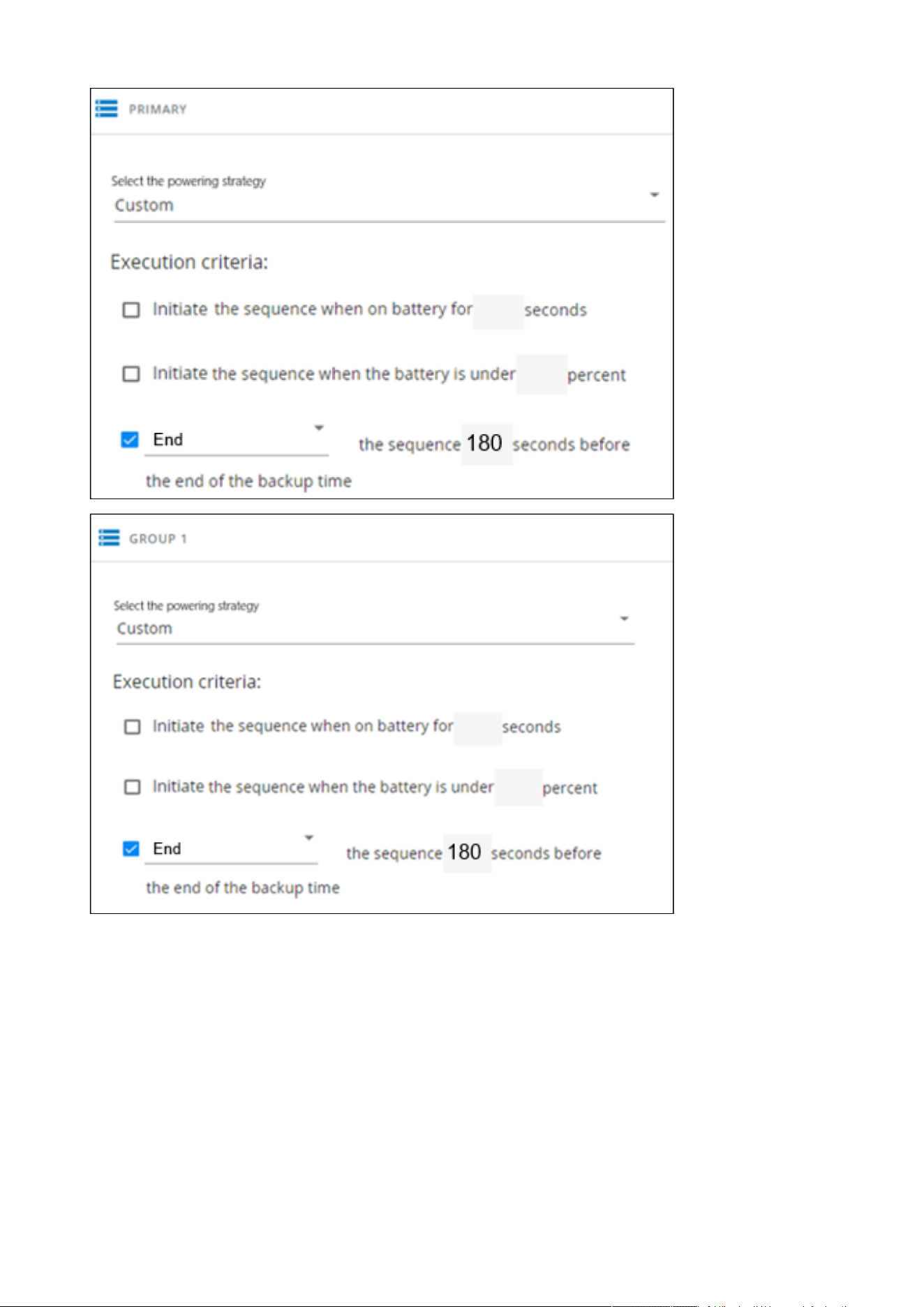
Powering down/up applications (examples)
Servicing the Network Management Module – 150
Critical equipment is the last one to power down, their availability will be maximized and their shutdown will end 180s before
the end of backup time.
3. Set Group 2 to:Immediate off.
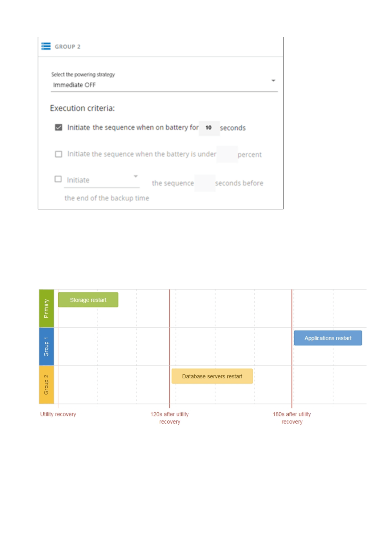
Powering down/up applications (examples)
Servicing the Network Management Module – 151
Non-priority equipmentimmediately shuts down when on battery for 10s to keep battery power for critical equipment.
4.3.3 Restart sequentially the IT equipment on utility recovery
4.3.3.1 Target
Restart the storage first (right after utility recovery), database servers next(2min after utility recovery) and applications last (3min
after utility recovery).
4.3.3.2 Step 1: Installation setup
4.3.3.2.1 Objective
Use load segmentation provided by the UPS to independently control the power supply of each IT equipment categories
(Applications, Database servers, Storage).
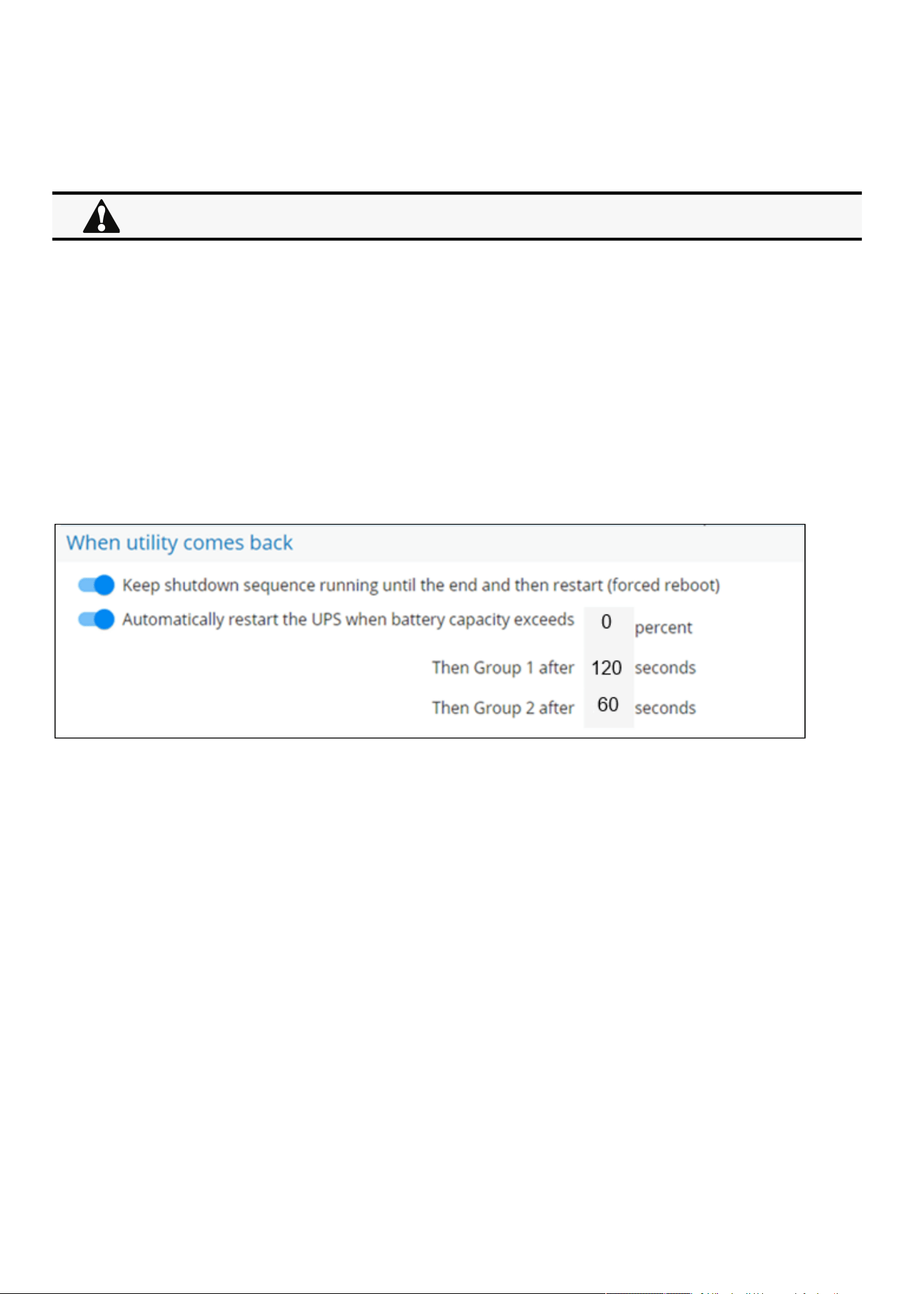
Checking the current firmware version of the Network Module
Servicing the Network Management Module – 152
•
•
•
•
•
•
This will allow to restart sequentially the IT equipment on utility recovery.
4.3.3.2.2 Resulting setup
UPS provides outlets (Group 1 and Group 2) and a primary output.
Connections to UPS can be done as described below:
Group 1: Applications
Group 2: Database servers
Primary: Storage
4.3.3.3 Step 2: Power outage policy settings
4.3.3.3.1 Objective
Use load segment restart settings to define restart sequencing.
4.3.3.3.2 Resulting setup
1. Navigate toContextual help>>>Protection>>>Shutdown on power outagepage and to the When utility comes backsection.
2.Enable the "Keep shutdown sequence running until the end and then restart (forced reboot)".
3. Enable the "Automatically restart the UPS when battery capacity exceeds" and set it to 0%.
The storage will restart first, right after utility recovery without waiting the battery capacity to exceed a % limit.
4. Set Then Group 1 after to 120s.
The database servers will restart 120s after the utility recovery.
5. Set Then Group 2 after to 60s.
The database servers will restart 180s after the utility recovery.
4.4 Checking the current firmware version of the Network Module
Currentfirmware of the Network Module can be accessed in :
The Top bar: Firmware version: x.xx.x
The Card menu :Contextual help>>>Maintenance>>>System information>>>Firmware information: Version x.xx.x
The Card menu : Contextual help>>>Maintenance>>>Firmware: Active FW version x.xx.x
4.5 Accessing to the latest Network Module firmware/driver/script
Download the latest Eaton Network Module firmware, driver or script from theEatonwebsitewww.eaton.com/downloads
When utility recovers, primary starts immediately.
Upgrading the card firmware (Web interface / shell script)
Servicing the Network Management Module – 153
1.
2.
4.6 Upgrading the card firmware (Web interface / shell script)
4.6.1 Web interface
To upgrade the Network module through the Web interface, refer to the section:Firmware upgrade through the Web interface.
4.6.2 Shell script
4.6.2.1 Prerequisite
Shell script uses the following tools: sshpass, scp.
To get it installed on your Linux host, use the following commands.
Debian/Ubuntu
$ sudo apt-get install sshpass scp
RedHat/Fedora/CentOS
$ sudo dnf install sshpass scp
Make shell script executable:
$ chmod 700 install_updatePackage.sh
4.6.2.2 Procedure
To upgrade the Network module using:
Open a shell terminal on your computer (Linux or cygwin; meaning real or emulated Linux operating system).
Use the shell script
install_updatePackage.sh
Usage: 'install_updatePackage.sh' [options]
Upgrade tool
Mandatory arguments are -f, -i, -u and -p
-h : show help
-f <path> : path of the upgrade file
-u <username> : username of a card user allowed to start upgrade
-p <password> : user password
-i <ipaddress> : ip address of the card to upgrade
-r : reboot the card after upgrade
4.6.3 Example:
$ ./install_updatePackage.sh -u admin -p <mypassword> -f FW_Update.tar -i <cardIpAddress> -r
For instructions on accessing to the latest firmware and script, refer to: Accessing to the latest firmware and script
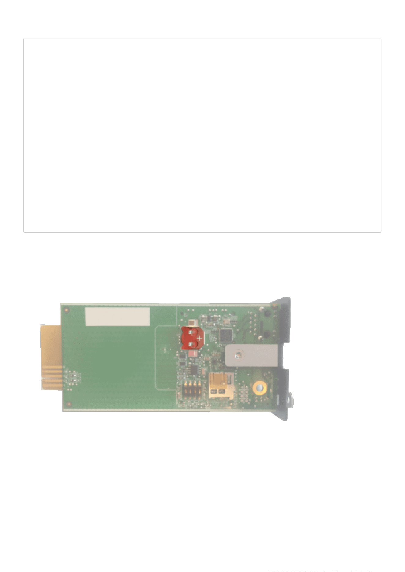
Changing the RTC battery cell
Servicing the Network Management Module – 154
STARTING UPDATE FROM: [FW_Update.tar] to [X.X.X.X]
Transfer by scp (FW_Update.tar) to [X.X.X.X]
Warning: Permanently added 'X.X.X.X' (ECDSA) to the list of known hosts.
Transfer done.
Check running upgrade status ...
Check firmware binary signature
Uncompress and flash upgrade - inProgress(%):11
Uncompress and flash upgrade - inProgress(%):28
Uncompress and flash upgrade - inProgress(%):44
Uncompress and flash upgrade - inProgress(%):61
Uncompress and flash upgrade - inProgress(%):78
Uncompress and flash upgrade - inProgress(%):92
Uncompress and flash upgrade - inProgress(%):100
Uncompress and flash upgrade - inProgress(%):100
Uncompress and flash upgrade
Executing post post_upgrade.sh script upgrade
Upgrade done
Warning: Permanently added 'X.X.X.X' (ECDSA) to the list of known hosts.
Rebooting...
res: Y
Update: OK
4.7 Changing the RTC battery cell
1.Access the Network Module, and then disconnect the Network cable, if needed.
2. Unscrew the Network Module and remove it from the slot.
3. Locate the RTC battery cell located on the back of the Network Module.
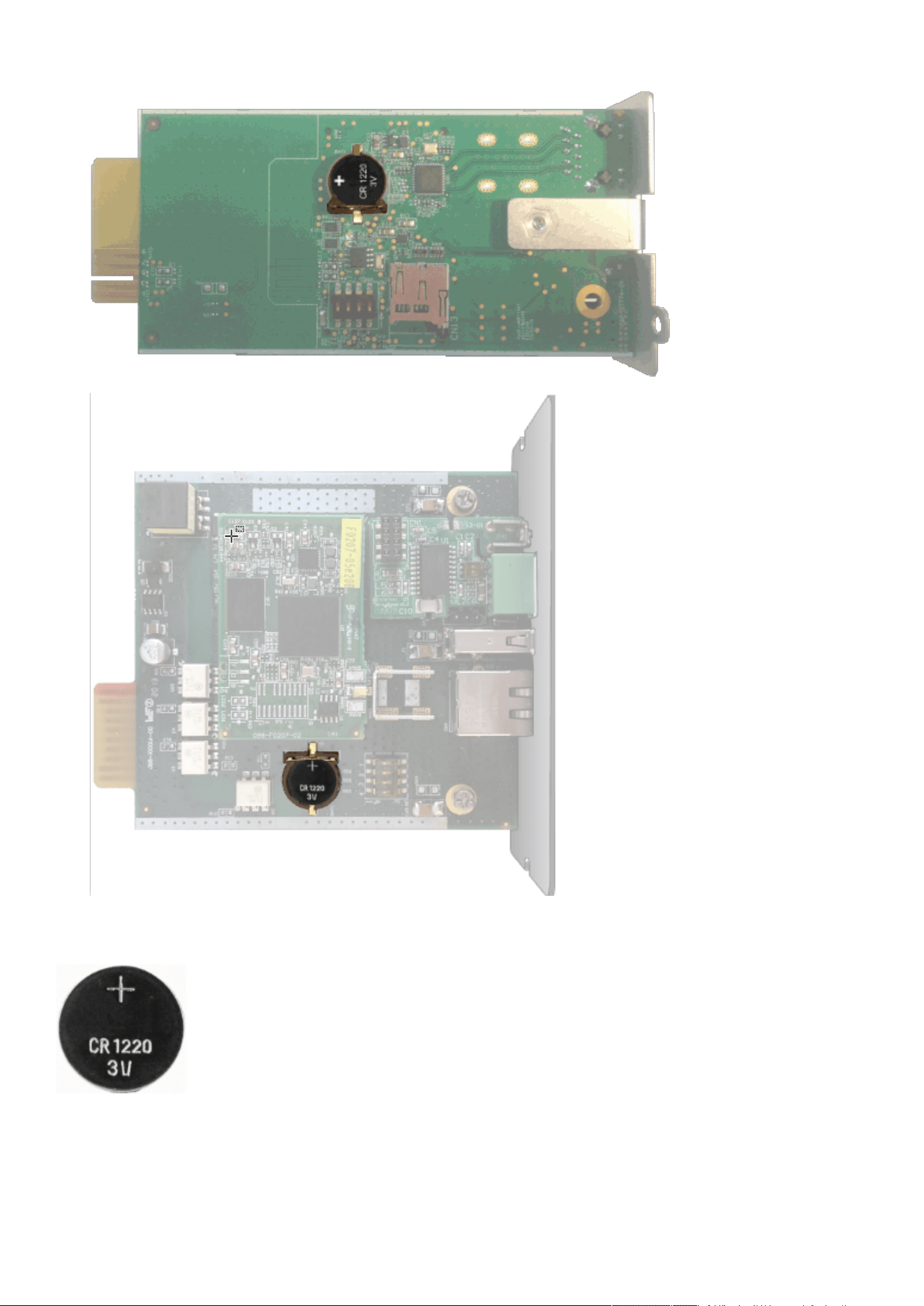
Changing the RTC battery cell
Servicing the Network Management Module – 155
4. Get a new battery cell (CR1220 type).
5. Replace the battery cell, the positive mark (+) should be visible when inserting it.
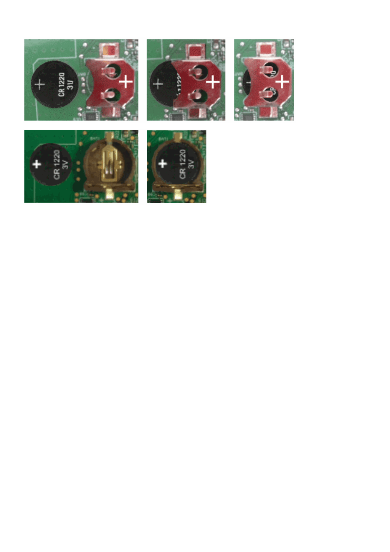
Changing the RTC battery cell
Servicing the Network Management Module – 156
6. Replace the Network Module and secure the screw, reconnect the Network cableif it was unplugged during the operation.
7. Connect the Network Module and set the date and time. For more information, see the Date & Timesection.

Updating the time of the Network Module precisely and permanently (ntp server)
Servicing the Network Management Module – 157
1.
2.
4.8 Updating the time of the Network Module precisely and
permanently (ntp server)
For an accurate and quick update of the RTC for the Network Module, we recommend implementing a NTP server as time source
for the Network Module.
LANs have aninternal NTP server (Domain Controller, mail servers, Outlook servers are generally time servers too) but you can use
a public ntp server like pool.ntp.org (after addition of the related rules to your firewall system).
For more information, see the Contextual help>>>Settings>>>General>>>System details>>>Time & date settingssection.
4.9 Synchronizing the time of the Network Module and the UPS
4.9.1 Automatic time synchronization
4.9.1.1 Every day at 5 a.m. (UTC time)
The UPS time (local time) is synchronized with the Network Module.
4.9.1.2 If the Network Module time is lost
The Network Module and the UPS time is synchronized with the oldest time between the last know Network Module time and the
UPS time.
4.9.2 Manual time synchronization
4.9.2.1 From the Network Module
On the Network Module, navigate toContextual help>>>Settings>>>General>>>System details>>>Time & date settings section
and update the time.
The UPS time (local time) is directly synchronized with the Network Module.
4.9.2.2 From the UPS
4.10 Changing the language of the web pages
Update thelanguage of the web page in the Settings menu.
Navigate toContextual help>>>User profile>>>Edit account.
Select the language, and then press the Save button.
This section is valid only when the UPS can manage date and time (refer to the UPS user manual for confirmation).
The Network Module use UTC time and manage the time zone and the DST.
The UPS manage only the local time.
When the time is updated on the UPS, it is not synchronized on the Network Module.
The language of the login page is English
by default or browser language when it is supported.
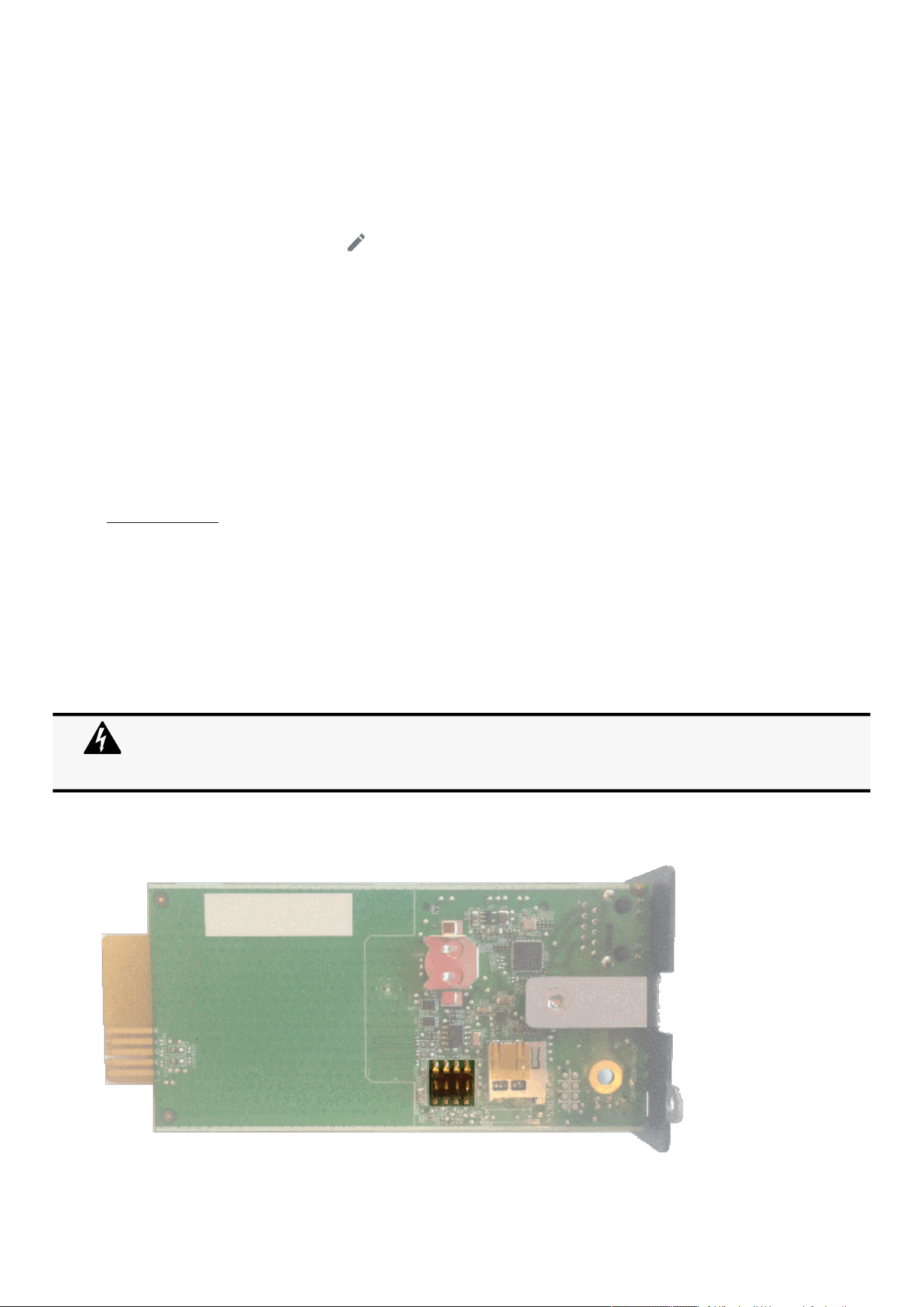
Resetting username and password
Servicing the Network Management Module – 158
•
•
•
1.
2.
3.
4.11 Resetting username and password
4.11.1 As an admin for other users
1.Navigate toContextual help>>>Settings>>>Local users.
2. Press the pen iconto edit user information:
3. Change username and save the changes.
4. Select Reset password and choosefrom the following options :
Generate randomly
Enter manually
Force password to be changed on next login
5. Enter your own password to confirm the changes.
6. Save the changes.
4.11.2 Resetting its own password
1.Navigate to Contextual help>>>User profile.
2. Press Change password
3. Enter your current password, the new password twice.
4. Press Submit to save the changes.
4.12 Recovering main administrator password
To recover the mainadministrator password,ask another administrator to initialize the password.
If it is not possible, proceed to the card sanitization:
Access the Network Module, disconnect the Network cable, if needed.
Unscrew the Network Module and remove it from the slot.
Locate the SANITIZATION switch that is located on the back of the Network Module.
Below instruction will sanitize the card and blank all the data.
Depending on your network configuration, the Network Module may restart with a different IP address.
Only main administrator user will remain with default login and password.
Refresh the browser after the Network module reboot time to get access to the login page.
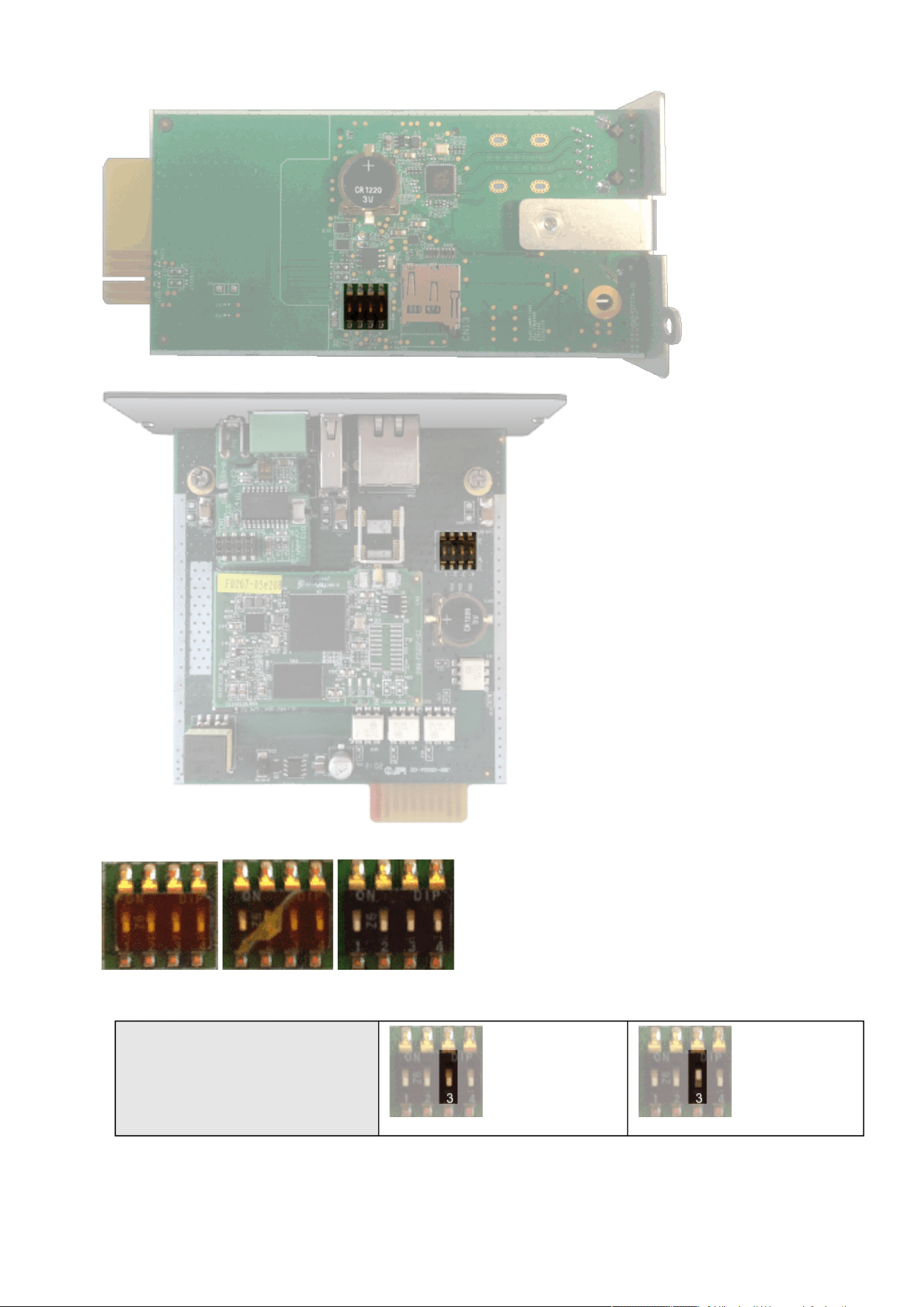
Recovering main administrator password
Servicing the Network Management Module – 159
4.
5.
Peel off the protection :
Change the position of switch number 3, this change is detected during next power ON and the sanitization will be applied :
Case 1 :

Switching to static IP (Manual) / Changing IP address of the Network Module
Servicing the Network Management Module – 160
6.
7.
8.
1.
2.
3.
•
•
•
4.
•
•
•
•
•
Case 2 :
Replace the Network Module and secure the screw, connect the Network cable, if needed.
Connect the Network Module byusing the default credentials of the main administrator : admin/admin.
You will beforced tochange the password accordingly to the current password strength rules.
4.13 Switching to static IP (Manual) / Changing IP address of the
Network Module
Administrators can switch to static IPin the Settings menu and change the IP address of the Network Module.
Navigate toContextual help>>>Settings>>>Network & Protocol>>>IPV4.
Select Manual (Static IP).
Input the following information:
IPv4 Address
Subnet Mask
Default Gateway
Save the changes.
4.14 Reading device information in a simple way
4.14.1 Web page
The product information is located in the Contextual help>>>Home>>>Energy flow diagram>>>Details,specifically with the button
on the top of the diagram:
4.15 Subscribing to a set of alarms for email notification
4.15.1 Example #1: subscribing only to one alarm (load unprotected)
Follow the steps below:
1.Navigate to Contextual help>>>Settings>>>General>>>Email notification settings.
2. Press the button New to create a new configuration.
3. Select:
Active: Yes
Configuration name: Load unprotected notification
Email address:[email protected]
Notify on events: Active
Always notify events with code: 81E (Load unprotected)
Changes of the switches 1, 2 or 4 has no effect.
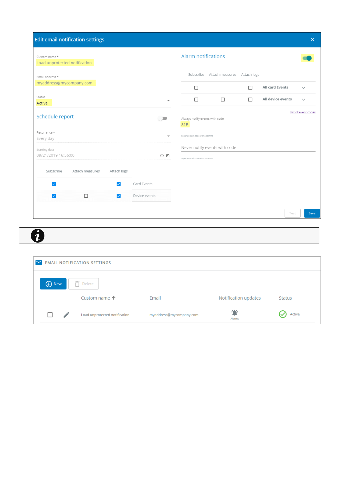
Subscribing to a set of alarms for email notification
Servicing the Network Management Module – 161
4. Press Save, the table will show the new configuration.
4.15.2 Example #2: subscribing to all Critical alarms and some specific
Warnings
Follow the steps below:
1.Navigate to Contextual help>>>Settings>>>General>>>Email notification settings.
2. Press the buttonNewto create a new configuration.
3. Select:
Logs will be attached by default in that example even if there is no subscription on card or device events.
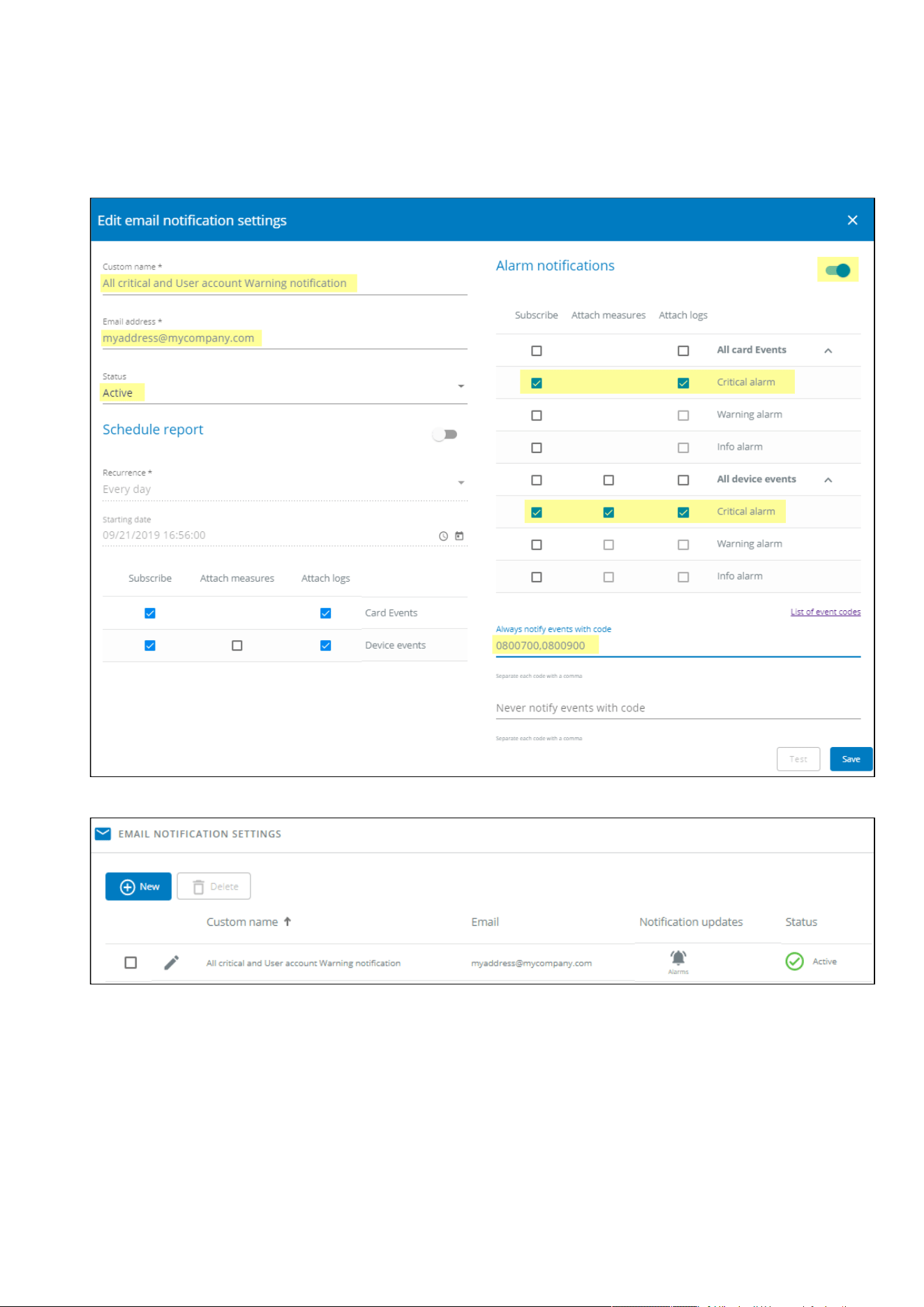
Subscribing to a set of alarms for email notification
Servicing the Network Management Module – 162
•
•
•
•
•
•
Active: Yes
Configuration name: ALL Critical and User account Warning notification
Email address: [email protected]
Notify on events: Active
Subscribe to Critical card events and Critical device events
Always notify events with code:0800700,0800900 (User account - password expired,User account- locked)
4. PressSave, the table will show the new configuration.
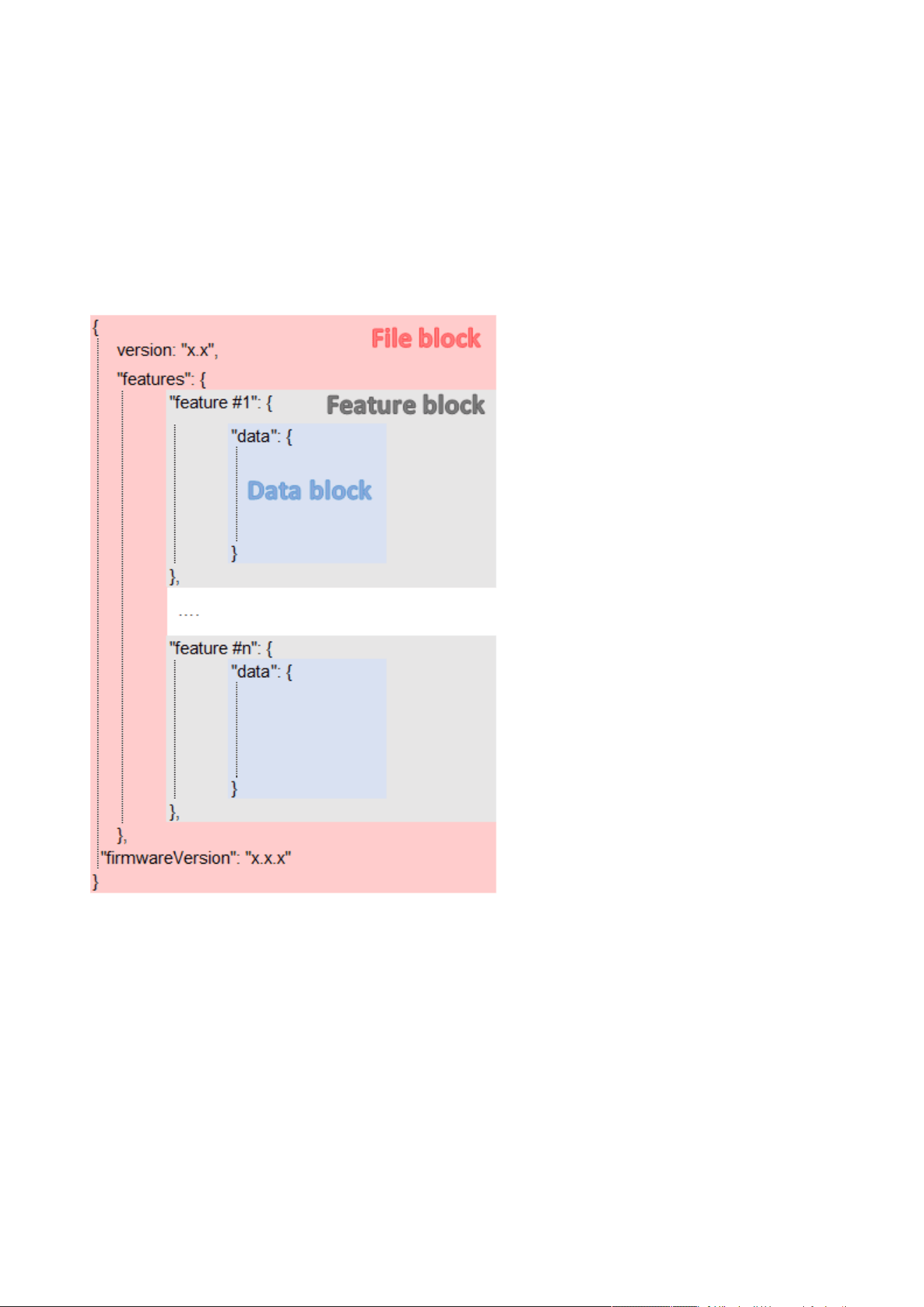
Saving/Restoring/Duplicating Network module configuration settings
Servicing the Network Management Module – 163
4.16 Saving/Restoring/Duplicating Network module configuration
settings
4.16.1 Modifying the JSON configuration settings file
4.16.1.1 JSON file structure
The JSON file is structured into 3 blocks:
4.16.1.1.1 File block
File block cannot be modified, this is the mandatory structure of the JSON file.
4.16.1.1.2 Feature block
Feature block contains the full definition of a feature.
If it is removed from the JSON file, this feature settings will not be updated/restored in the card.
4.16.1.1.3 Data block
Data block contains all the feature settings values.
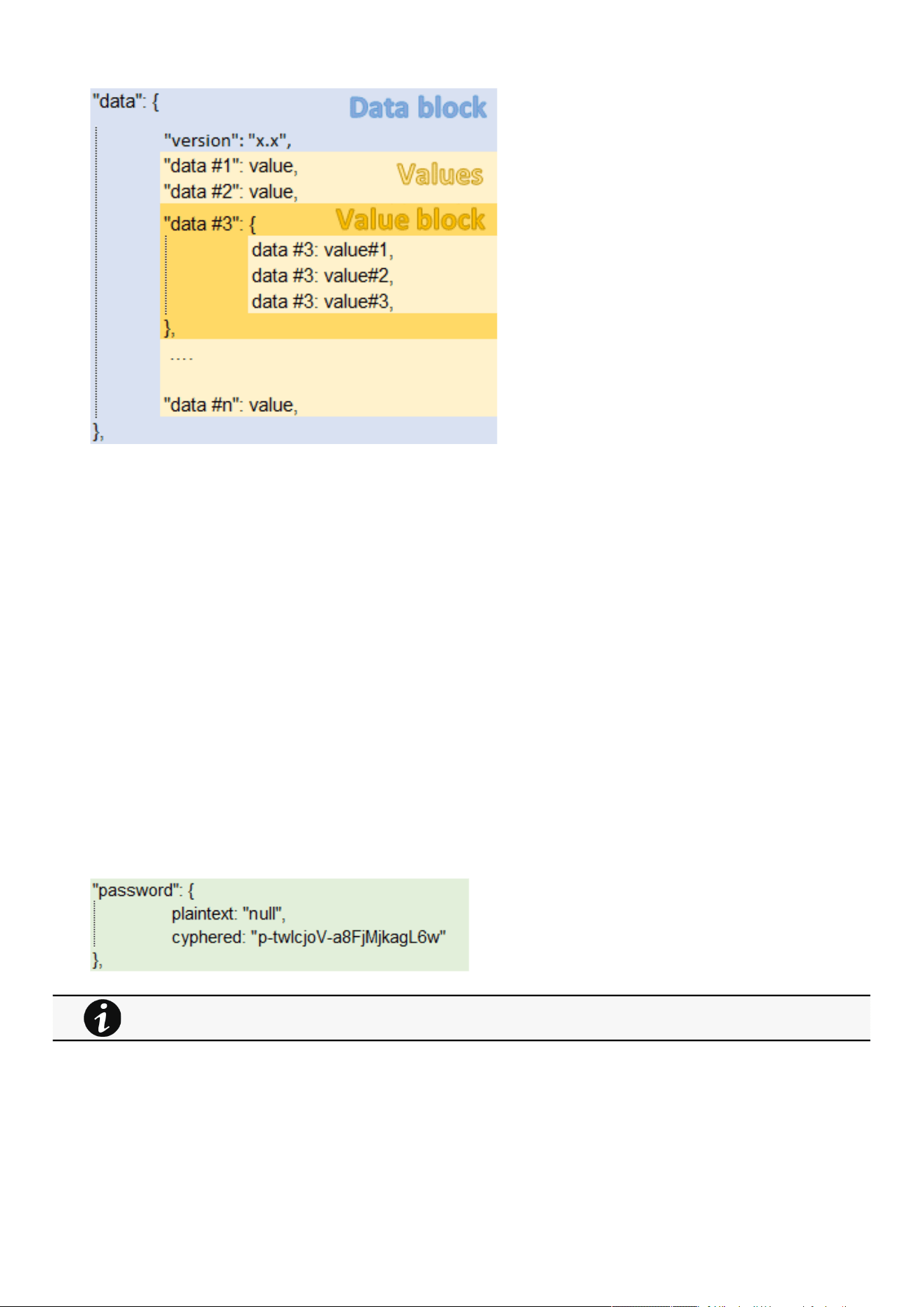
Saving/Restoring/Duplicating Network module configuration settings
Servicing the Network Management Module – 164
a Data block
Data block cannot be modified, this is the mandatory structure of the JSON file.
b Value block
If some values inside the Value block need to be kept, Value block structure cannot be modified, this is the mandatory structure of
the JSON file.
If it is removed from the JSON file, these values will not be updated/restored.
c Values
Values can be kept as is, modified or removed.
Removed values will not be updated/restored.
4.16.1.2 Sensitive data (like passwords)
JSON file structure will slightly varies if sensitive data are exported with passphrase or not.
4.16.1.2.1 The JSON file is saved using passphrase (preferred)
All sensitive data will have below structure:
4.16.1.2.2 The JSON file is saved without passphrase
All sensitive data will have below structure:
When restoring the file, the corresponding setting will be updated based on the cyphered value.
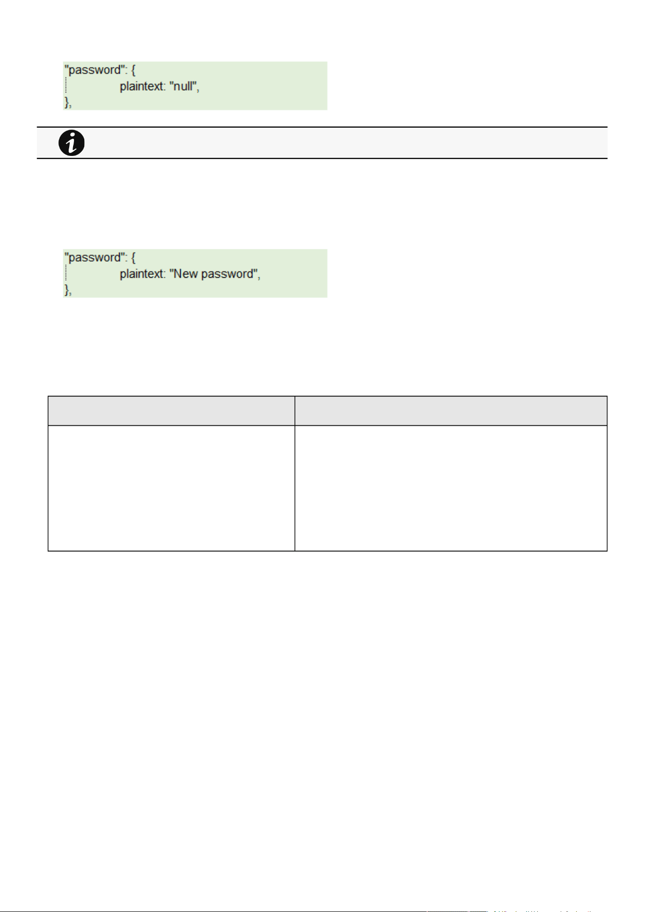
Saving/Restoring/Duplicating Network module configuration settings
Servicing the Network Management Module – 165
4.16.1.3 Modifying JSON file examples
4.16.1.3.1 Modifying sensitive data
To change sensitive data, plain text must be filled with the new valueand the Cyphered entry (if existing) must be removed:
4.16.1.3.2 Adding local users
Adding or modifying local users is not yet available, only the predefined account (main administrator) can be modified.
4.16.1.3.3 Modifying SNMP settings
Original file: Modified file:
SNMP disabled SNMP enabled on port 161
SNMPv1 disabled
SNMPv3 enabled
2 x accounts
1 x read only user (enabled) with Auth-Priv security level and passwords
1x read write user (enabled) with Auth-Priv security level and passwords
1 x active trap
When restoring the file, the corresponding setting will not be set.
This may lead to restoration failure if corresponding setting was not previously set with a valid value.
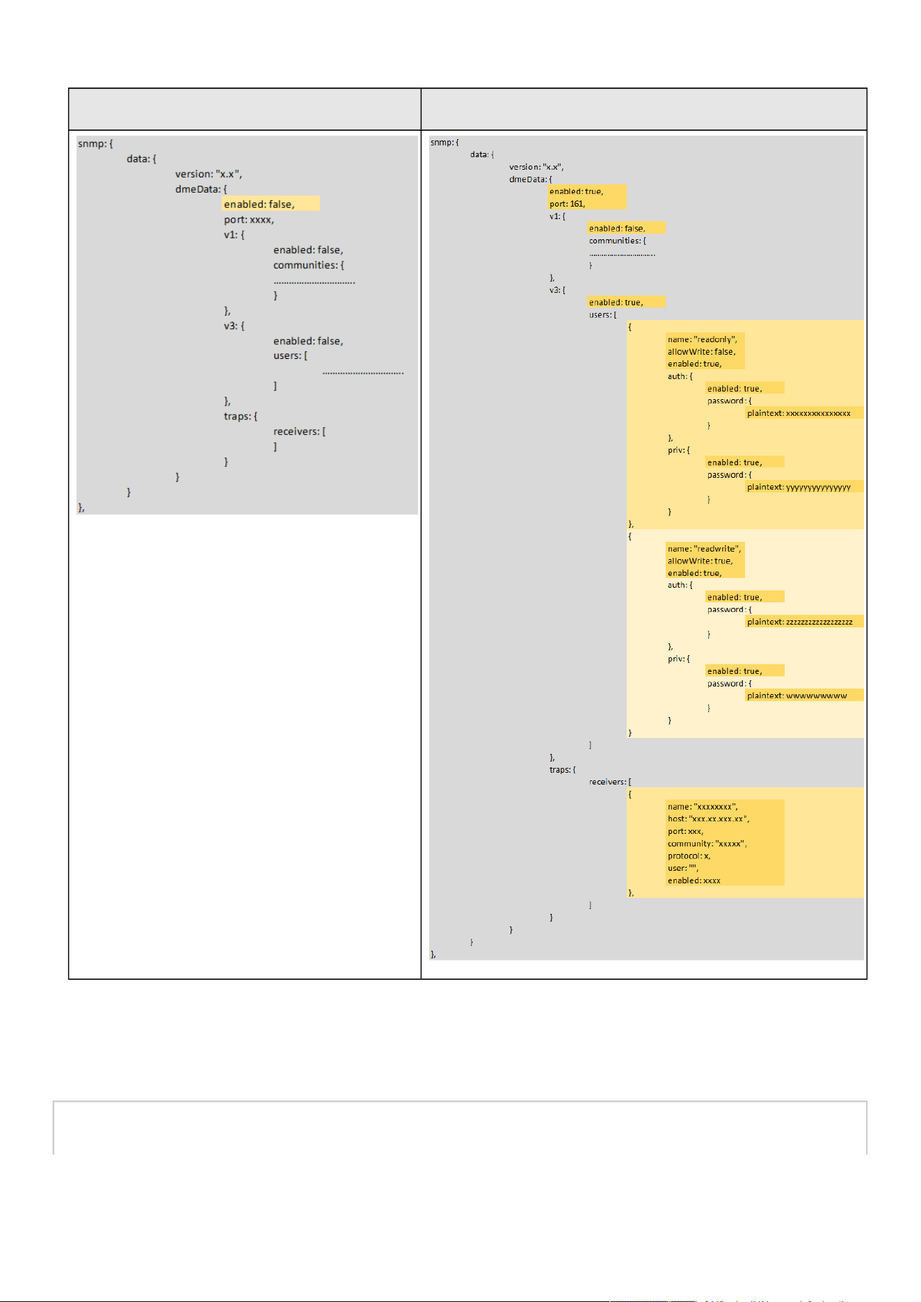
Saving/Restoring/Duplicating Network module configuration settings
Servicing the Network Management Module – 166
Original file: Modified file:
4.16.1.3.4 Making a partial update/restoration
a Example: Updating/Restoring onlyLDAP settings
If you restore below JSON content, only LDAP settings will be updated/restored, everything else will remain unchanged.
{
"version": "x.x",

Saving/Restoring/Duplicating Network module configuration settings
Servicing the Network Management Module – 167
"features": {
"ldap": {
"data": {
"version": "x.x",
"certificateData": [],
"dmeData": {
"enabled": true,
"baseAccess": {
"security": {"ssl": 1,"verifyTlsCert": false},
"primary": {"name": "Primary","hostname": "xxxxxxxxx","port": xxxx},
"secondary": {"name": "xxxxxx","hostname": "xxxxxx","port": xxxx},
"credentials": {
"anonymousSearchBind": false,
"searchUserDN":
"CN=xxxx,OU=xxxx,OU=xxxx,OU=xxxx,DC=xxxx,DC=xxxx",
"password": {"plaintext": null}},
"searchBase": {"searchBaseDN": "DC=xxx,DC=xxx,DC=xxx"}
},
"requestParameters": {
"userBaseDN": "OU=xxxx,DC=xxxx",
"userNameAttribute": "xxxx",
"uidAttribute":"objectSid:x-x-x-xx-xxxxxxxxxx-xxxxxxxxxx-xxxxxxxxxx",
"groupBaseDN": "OU=xxxx,DC=xxxx",
"groupNameAttribute": "xx",
"gidAttribute":"objectSid:x-x-x-xx-xxxxxxxxxx-xxxxxxxxxx-xxxxxxxxxx"
},
"profileMapping": [
{ "remoteGroup": "xxxxxxxxxxxxxx","profile": 1},
{ "remoteGroup": "xxxxxxxxxxxxxx","profile": 2},
{ "remoteGroup": "","profile": 0},
{ "remoteGroup": "","profile": 0},
{ "remoteGroup": "","profile": 0}
]
}
}
},
},
"firmwareVersion": "x.x.x"
}
4.16.2 Saving/Restoring/Duplicating settings through the CLI
Navigate to Information>>>CLI>>>save_configuration | restore_configurationsection to get example on how to save and restore
settings through the CLI.
4.16.3 Saving/Restoring/Duplicating settings through the Web interface
Navigate to Contextual help>>>Maintenance>>>Services section to getinformation on how to save and restore settings through
the Web interface.

Cybersecurity considerations for electrical distribution systems
Securing the Network Management Module – 168
•
•
•
•
5 Securing the Network Management Module
5.1 Cybersecurity considerations for electrical distribution systems
5.1.1 Purpose
The purpose of this section is to provide high-level guidance to help customers across industries and applications apply Eaton
solutions for power management of electrical systems in accordance with current cybersecurity standards.
This document is intended to provide an overview of key security features and practices to consider in order to meet industry
recommended standards and best practices.
5.1.2 Introduction
Every day, cyber-attacks against government and commercial computer networks number in the millions. According to U.S. Cyber
Command, Pentagon systems are probed 250,000 times per hour. Similar attacks are becoming more prevalent on other kinds of
information-based smart networks as well, such as those that operate buildings and utility systems. Whether the objective is to
steal intellectual property or halt operations, the tools and the techniques used for unauthorized network access are increasingly
sophisticated.
5.1.3 Connectivity—why do we need to address cybersecurity for
industrial control systems (ICS)?
There is increasing concern regarding cybersecurity across industries where companies are steadily integrating field devices into
enterprise-wide information systems. This occurs in discrete manufacturing and process industrial environments, a wide range of
general and specific purpose commercial buildings, and even utility networks. Traditionally, electrical systems were controlled
through serial devices connected to computers via dedicated transceivers with proprietary protocols. In contrast, today’s control
systems are increasingly connected to larger enterprise networks, which can expose these systems to similar vulnerabilities that
are typically found in computer systems. The differences between information technology (IT) and ICS networks can be
summarized as follows:
The main focus of the IT network is to ensure the confidentiality and the integrity of the data using rigorous access control
and data encryption
The main focus of the ICS network is safety, availability, and integrity of data
Enterprise security protects the servers’ data from attack
Control system security protects the facility’s ability to safely and securely operate, regardless of what may befall the rest of
the network
5.1.4 Cybersecurity threat vectors
Cybersecurity threat vectors are paths or tools that an entity can use to gain access to a device or a control network in order to
deliver a malicious attack. Figure below shows examples of attack vectors on a network that might otherwise seem secure.
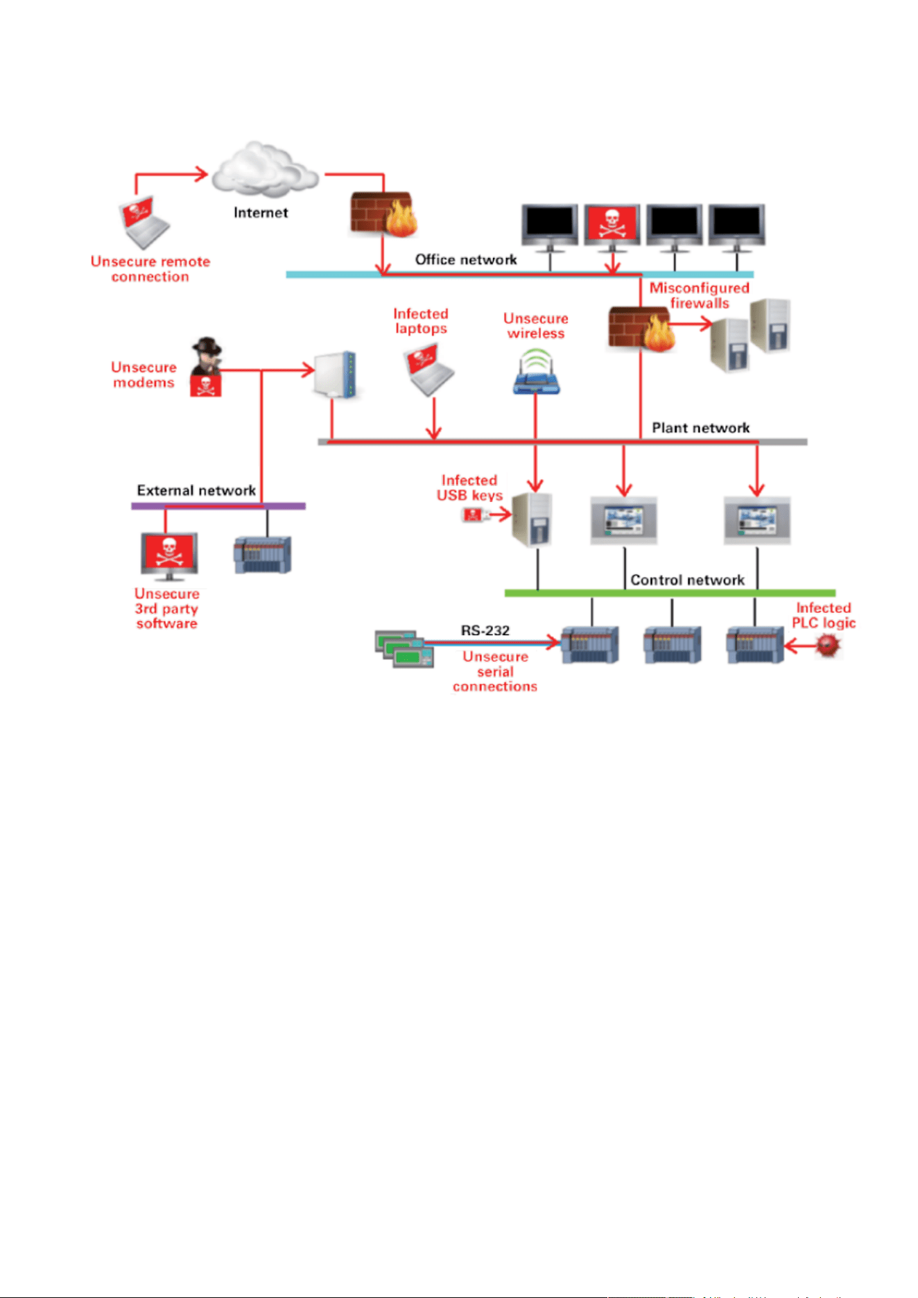
Cybersecurity considerations for electrical distribution systems
Securing the Network Management Module – 169
•
•
•
•
•
•
•
•
•
•
5.1.4.1 Paths to the control network
The paths in above figure include:
External users accessing the network through the Internet
Misconfigured firewalls
Unsecure wireless routers and wired modems
Infected laptops located elsewhere that can access the network behind the firewall
Infected USB keys and PLC logic programs
Unsecure RS-232 serial links
The most common malicious attacks come in the following forms:
Virus—a software program that spreads from one device to another, affecting operation
Trojan horse—a malicious device program that hides inside other programs and provides access to that device
Worm—a device program that spreads without user interaction and affects the stability and performance of the ICS network
Spyware—a device program that changes the configuration of a device
5.1.5 Defense in depth
While there are differences between traditional IT systems and ICS, the fundamental concept of “defense in depth” is applicable to
both. Defense in depth is a strategy of integrating technology, people, and operations capabilities to establish variable barriers
across multiple layers of an organization. These barriers include electronic countermeasures such as firewalls, intrusion detection
software/components, and antivirus software, coupled with physical protection policies and training. Fundamentally, the barriers are
intended to reduce the probability of attacks on the network and provide mechanisms to detect “intruders.”

Cybersecurity considerations for electrical distribution systems
Securing the Network Management Module – 170
•
•
•
•
•
5.1.6 Designing for the threat vectors
5.1.6.1 Firewalls
Firewalls provide the capability to add stringent and multifaceted rules for communication between various network segments and
zones in an ICS network. They can be configured to block data from certain segments, while allowing the relevant and necessary
data through. A thorough understanding of the devices, applications, and services that are in a network will guide the appropriate
deployment and configuration of firewalls in a network. Typical types of firewalls that can be deployed in a network include:
Packet filter or boundary firewalls that work on the network layer
These firewalls mainly operate at the network layer, using pre-established rules based on port numbers and protocols to
analyze the packets going into or out of a separated network.
These firewalls either permit or deny passage based on these rules.
Host firewalls
These firewalls are software firewall solutions that protect ports and services on devices. Host firewalls can apply rules that
track, allow, or deny incoming and outgoing traffic on the device and are mainly found on mobile devices, laptops, and
desktops that can be easily connected to an ICS.
Application-level proxy firewalls
These firewalls are highly secure firewall protection methods that hide and protect individual devices and computers in a
control network. These firewalls communicate at the application layer and can provide better inspection capabilities. Because
they collect extensive log data, application-level proxy firewalls can negatively impact the performance of an ICS network.
Stateful inspection firewalls
These firewalls work at the network, session, and application layers of the open system interconnection (OSI). Stateful
inspection firewalls are more secure than packet filter firewalls because they only allow packets belonging to allowed
sessions.
These firewalls can authenticate users when a session is established and analyze a packet to determine whether they contain
the expected payload type or enforce constraints at the application layer.
SCADA hardware firewalls
These are hardware-based firewalls that provide defense for an ICS based on observing abnormal behavior on a device within
the control network. For example, if an operator station computer suddenly attempts to program a PLC, this activity could be
blocked and an alarm could be raised to prevent serious risk to the system.
5.1.6.2 Demilitarized zones (DMZ)
Network segmentation is a key consideration in establishing secure control networks. Firewalls should be used to create DMZ by
grouping critical components and isolating them from the traditional business IT network. A three-tier architecture should be
employed at a minimum, with a DMZ between the organization’s core network and an isolated control system’s network as shown
in below figure.
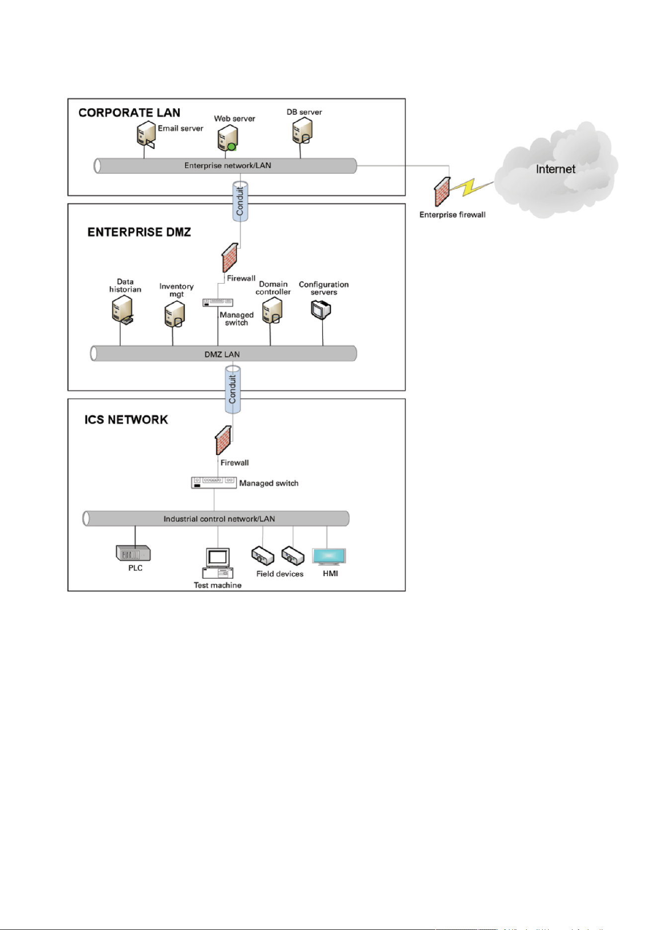
Cybersecurity considerations for electrical distribution systems
Securing the Network Management Module – 171
•
•
•
•
5.1.6.2.1 Three-tier architecture for a secure control network
Above figure shows that the control networks are divided into layers or zones based on control functions, which are then
connected by conduits (connections between the zones) that provide security controls to:
Control access to zones
Resist denial of services (DOS) attacks or the transfer of malware
Shield other network systems
Protect the integrity and the confidentiality of network traffic
Beyond network segmentation, access control (both physical and logical) should be defined and implemented.
The key consideration when designing access control is defining the required interactions both within a given zone and between
zones. These interactions should be mapped out clearly and prioritized based on need. It is important to realize that every hole
poked in a firewall and each non-essential functionality that provides access or creates additional connectivity increases potential
exposure to attacks. A system then becomes only as secure as the devices connecting to it.
If mapped correctly, the potential adverse impact to control system reliability and functionality should be negligible. However, this
element introduces additional costs (in terms of firewall and other network infrastructure) and complexity to the environment.

Cybersecurity considerations for electrical distribution systems
Securing the Network Management Module – 172
•
•
•
•
•
•
•
•
5.1.6.3 Intrusion detection and prevention systems (IDPS)
These are systems that are primarily focused on identifying possible incidents in an ICS network, logging the information about
them, attempting to stop them, and reporting them to ICS security administrators.
Because these systems are critical in an ICS network, they are regular targets for attacks and securing them is extremely important.
The type of IDPS technology deployed will vary with the type of events that need to be monitored.
There are four classes of IDPS technology:
Network-based IDPS monitors network traffic for particular ICS network segments or devices and analyzes the network and
application protocol activity to identify suspicious activity
Wireless IDPS monitors and analyzes wireless network traffic to identify suspicious activity involving the ICS wireless
network protocol
Network behavior analysis IDPS examines ICS network traffic to identify threats that generate unusual traffic flows such as
DOS attacks
Host-based IDPS monitors the characteristics and the events occurring within a single ICS network host for suspicious
activity
5.1.7 Policies, procedures, standards, and guidelines
For the defense in depth strategy to succeed, there must be well-documented and continuously reviewed policies, procedures,
standards, and guidelines.
Policies provide procedures or actions that must be carried out to meet objectives and to address the who, what, and why
Procedures provide detailed steps to follow for operations and to address the how, where, and when
Standards typically refer to specific hardware and software, and specify uniform use and implementation of specific
technologies or parameters
Guidelines provide recommendations on a method to implement the policies, procedures, and standards
5.1.7.1 Understanding an ICS network
Creating an inventory of all the devices, applications, and services that are hosted in a network can establish an initial baseline for
what to monitor. Once those components are identified and understood, control, ownership, and operational consideration can be
developed.
5.1.7.2 Log and event management
It is important to understand what is happening within the network from both a performance and security perspective. This is
especially true in a control systems environment.
Log and event management entails monitoring infrastructure components such as routers, firewalls, and IDS/IPS, as well as
host assets. Security Information and Event Management (SIEM) systems can collect events from various sources and provide
correlation and alerts.
Generating and collecting events, or even implementing a SIEM is not sufficient by itself. Many organizations have SIEM solutions,
but alerts go unwatched or unnoticed.
Monitoring includes both the capability to monitor environments and the capacity to perform the monitoring. Capability relates to
the
design and the architecture of the environment. Has it been built in a manner that takes into consideration the ability to monitor?
Capacity speaks to the resources (personnel, tools, expertise) needed to perform meaningful interpretation of the information and
initiate timely and appropriate action.
Through monitoring, the organization can identify issues such as suspicious or malicious activities. Awareness can be raised when
new (potentially unauthorized) devices appear in the environment. Careful consideration should be taken into account to ensure that
log and event management does not adversely impact the functionality or the reliability of the control system devices.
5.1.7.3 Security policy and procedures
It is important to identify “asset owners,” and to develop policies and procedures for a cybersecurity program. These policies need
to be practical and enforceable in order to be effective. Policies should also address access related issues, such as physical access,
contractors, and vendors.

Cybersecurity considerations for electrical distribution systems
Securing the Network Management Module – 173
•
•
•
•
•
•
•
•
•
•
•
•
•
•
•
•
•
•
Existing (traditional) IT standards and policies may not apply (or have not been considered) for control systems. A gap analysis
should be performed to determine which components are not covered (or not adequately covered) by existing policies.
Relationships with existing policies and standards should be explicitly identified and new or supporting policies should be
developed. It is important that industrial control system administrators have proper authorizations and full support of their
management to implement policies that will help secure the ICS network.
5.1.7.4 ICS hardening
The goal for system hardening is to reduce as many security risks as possible by securely configuring ICS networks. The idea is to
establish configurations based on what is required and eliminate unnecessary services and applications that could potentially
provide another possible entry point to an intruder.
Minimum security baselines should be established for the various platforms and products deployed (operating system, application,
and infrastructure elements such as drives, meters, HMI devices). The following actions should be implemented where applicable:
Disable unnecessary services
Disable anonymous FTP
Do not use clear text protocols (e.g., use SSH v2 instead of Telnet)
Install only required packages/applications/features
Deploy antivirus solutions (where possible)
Disable or otherwise control use of USB devices
Establish a warning banner
Change default passwords (e.g., SNMP)
It may be easier to implement these actions on devices for which you control the base operating system platform. However,
several
of the items listed above can be configured from the product specific configuration options.
Changes such as these could potentially impact the functionality of a control system device. Extensive testing needs to be
conducted before deployment to minimize this impact.
5.1.7.5 Continuous assessment and security training
It is critical that ICS network administrators and regular users be properly trained to ensure the security of the ICS and the safety of
the people who operate and depend on it.
Ongoing vulnerability assessments are critical to identify issues and understand the effectiveness of other defensible network
elements.
Assessments should include testing and validating the following:
Monitoring capabilities and alerts are triggered and responded to as expected
Device configuration of services and applications
Expected connectivity within and between zones
Existence of previously unknown vulnerabilities in the environment
Effectiveness of patching
A program should be established for performing assessments.
The actual assessment should be performed by a qualified resource, which can be an in-house or third-party organization.
Regardless of who performs the assessments, in-house resources need to be involved in the planning, scoping, and supporting of
assessment activities and must be appropriately trained to do so.
Assessments should be conducted according to a methodology that is clearly defined to address:
Physical security
People and processes
Network security
Host security
Applications security (both internally developed and commercially off-the-shelf (COTS))
5.1.7.6 Patch management planning and procedures
A patching and vulnerability management process should be established based on the timely awareness of issues and appropriate
action. This process should take all of the elements that make up the control system environment into consideration.
Information resources should be identified for vulnerability and advisory information for the various components in the environment.
These should include vendor-specific sources as well as other public or commercial services that provide vulnerability advisory
information. For example, the National Vulnerability Database (NVD) provides information related to vulnerabilities identified in

Cybersecurity considerations for electrical distribution systems
Securing the Network Management Module – 174
general IT components, while the Industrial Control Systems Cyber Emergency Response Team (ICS-CERT) publishes advisories
specific to control systems.
A regular patch deployment schedule should be established for each component in the environment. Depending on the component,
this could range from a monthly schedule to an as-needed deployment, depending on the historical frequency of patch or
vulnerability related issues for the component or the vendor. Additionally, out-of-band or emergency patch management needs to
be
considered and qualifications need to be defined.
Vulnerability information and advisories should be reviewed regularly and assessments should be performed to determine the
relative severity and urgency of issues.
Elements of the process should also include the preparation, scheduling, and change controls; testing and rollback procedures;
and pre-deployment notification to stakeholders that includes scope, expectations, and reporting. Testing is a significant element,
as
the effect of the patch application needs to be clearly understood; unintended or unexpected impacts to a control system
component influence the decision to deploy a patch. In the event that it isdetermined that a patch cannot be safely deployed but
the severity of the issue represents a significant concern, compensating controls should be investigated.
5.1.8 Conclusion
To protect important assets, all organizations must take cybersecurity threats seriously and meet them proactively with a system-
wide defensive approach specific to organizational needs.
There is no protection method that is completely secure. A defense mechanism that is effective today may not be effective
tomorrow– the ways and means of cyber-attacks constantly change. It is critical ICS administrators remain aware of changes in
cybersecurity and continue to work to prevent any potential vulnerabilities in the systems they manage.
5.1.9 Terms and definitions
DMZ A demilitarized zone is a logical or physical sub network that interfaces an organization’s external
services to a larger, untrusted network and providing an additional layer of security.
Encryption The process of transforming plain or clear text using analgorithm to make it unreadable to anyone
except those possessing special knowledge.
ICS A device or set of device that manage, command, direct, or regulate the behavior of other devices
or systems.
Protocol A set of standard rules for data representation, signaling, authentication, and error detection
required to send information over a communications channel
5.1.10 Acronyms
COTS Commercially Off-the-Shelf
DMZ Demilitarized Zone
DOS Denial of Service
FTP File Transfer Protocol
HMI Human Machine Interface
ICS Industrial Control Systems
ICS-CERT Industrial Control Systems - Cyber Emergency Response Team
IDPS Intrusion Detection and Prevention Systems
IDS Intrusion Detection Systems
IPS Intrusion Prevention Systems
IT Information Technology
NVD National Vulnerability Database
OSI Open System Interconnection
PLC Programmable Logic Controller

Cybersecurity considerations for electrical distribution systems
Securing the Network Management Module – 175
SCADA Supervisory Control and Data Acquisition
SNMP Simple Network Management Protocol
SSH Secure Shell
SIEM Security Information and Event Management
USB Universal Serial Bus
5.1.11 References
[1] Recommended Practice: Improving Industrial Control Systems Cybersecurity with Defense-In-Depth Strategies, October 2009
https://ics-cert.us-cert.gov/sites/default/files/FactSheets/NCCIC%20ICS_FactSheet_Defense_in_Depth_Strategies_S508C.pdf
[2] NIST.SP.800-82 Guide to Industrial Control Systems (ICS) Security, June 2011
http://csrc.nist.gov/publications/nistpubs/800-82/SP800-82-final.pdf
[3] NIST.SP.800-94 Guide to Intrusion Detection and Prevention Systems (IDPS), Feb 2007
http://csrc.nist.gov/publications/nistpubs/800-94/SP800-94.pdf
[4] Common Cybersecurity Vulnerabilities in Industrial Control Systems, May 2011
http://ics-cert.uscert.gov/sites/default/files/recommended_practices/DHS_Common_Cybersecurity_Vulnerabilities_ICS_2010.pdf
[5] The Tao of Network Security Monitoring, 2005 Richard Bejtlich

Cybersecurity recommended secure hardening guidelines
Securing the Network Management Module – 176
•
•
•
•
•
•
•
•
•
•
•
•
•
•
•
•
•
5.2 Cybersecurity recommended secure hardening guidelines
5.2.1 Introduction
This Network modulehas been designed with cybersecurity as an important consideration. Number of features are offered in the
product to address cybersecurity risks. These Cybersecurity Recommendations provide information to help users to deploy and
maintain the product in a manner that minimizes the cybersecurity risks. These Cybersecurity Recommendations are not intended
to provide a comprehensive guide to cybersecurity, but rather to complement customers’ existing cybersecurity programs.
Eaton is committed to minimizing the cybersecurity risk in its products and deploying cybersecurity best practices in its products
and solutions, making them more secure, reliable and competitive for customers.
The following whitepapers are available for more information on general cybersecurity best practices and guidelines:
Cybersecurity Considerations for Electrical Distribution Systems (WP152002EN):http://www.eaton.com/ecm/groups/public/@pub/
@eaton/@corp/documents/content/pct_1603172.pdf
Cybersecurity Best Practices Checklist Reminder (WP910003EN):http://www.cooperindustries.com/content/dam/public/
powersystems/resources/library/1100_EAS/WP910003EN.pdf
Cybersecurity Best Practices for Modern Vehicles - NHTSA:https://www.nhtsa.gov/staticfiles/nvs/pdf/
812333_CybersecurityForModernVehicles.pdf
5.2.2 Secure configuration guidelines
5.2.2.1 Asset Management
Keeping track of software and hardware assets in your environment is a pre-requisite for effectively managing cybersecurity. Eaton
recommends that you maintain an asset inventory that uniquely identifies each important component.
To facilitate this, Network modulesupports the following identifying information:
5.2.2.1.1 Network Module identification and its firmware information
It can be retrieved by navigating to
Card>>>System information or Maintenance>>>System information
.
Identification
System name
Product
Physical name
Vendor
UUID
Part number
Serial number
Hardware version
Location
Contact
Firmware information
Firmware version
Firmware SHA
Firmware date
Firmware installation date
Firmware activation date
Bootloader version
5.2.2.1.2 Communication settings
It can be retrieved by navigating to
Settings>>>Network orSettings>>>Network & Protocol
LAN
Link status

Cybersecurity recommended secure hardening guidelines
Securing the Network Management Module – 177
•
•
•
•
•
•
•
•
•
•
•
•
•
•
•
•
•
•
•
•
•
•
•
•
MAC address
Configuration
IPV4
Status
Mode
Address
Netmask
Gateway
Domain
Mode
FQDN
Primary DNS
Secondary DNS
IPV6
Status
Mode
Addresses
5.2.2.1.3 UPS details
It can be retrieved by navigating to
Home>>>Details or Home>>>Energy flow .
Details
Name
Model
P/N
S/N
Location
FW version
5.2.2.2 Risk Assessment
Eaton recommends conducting a risk assessment to identify and assess reasonably foreseeable internal and external risks to the
confidentiality, availability and integrity of the system | device and its environment. This exercise should be conducted in
accordance with applicable technical and regulatory frameworks such as IEC 62443 and NERC-CIP. The risk assessment should be
repeated periodically.
5.2.2.3 Physical Security
An attacker with unauthorized physical access can cause serious disruption to system/device functionality. Additionally, Industrial
Control Protocols don’t offer cryptographic protections, making ICS and SCADA communications especially vulnerable to threats to
their confidentiality. Physical security is an important layer of defense in such cases. The Network moduleis designed to be
deployed and operated in a physically secure location. Following are some best practices that Eaton recommends to physically
secure your system/device:
Secure the facility and equipment rooms or closets with access control mechanisms such as locks, entry card readers,
guards, man traps, CCTV, etc. as appropriate.
Restrict physical access to cabinets and/or enclosures containing the Network moduleand the associated system. Monitor
and log the access at all times.
Physical access to the telecommunication lines and network cabling should be restricted to protect against attempts to
intercept or sabotage communications. It’s a best practice to use metal conduits for the network cabling running between
equipment cabinets.
The Network modulesupports the following physical access ports: RJ45, USB A, USB Micro-B. Access to these ports should
be restricted.
Most of above information are discoverable using SNMP, refer to Settings>>>SNMP.

Cybersecurity recommended secure hardening guidelines
Securing the Network Management Module – 178
•
•
•
•
•
•
•
•
•
•
•
•
•
•
Do not connect removable media (e.g., USB devices, SD cards, etc.) for any operation (e.g., firmware upgrade, configuration
change, or boot application change) unless the origin of the media is known and trusted.
Before connecting any portable device through a USB port or SD card slot, scan the device for malware and viruses.
5.2.2.4 Account management
Logical access to the system | device should be restricted to legitimate users, who should be assigned only the privileges
necessary to complete their job roles/functions. Some of the following best practices may need to be implemented by
incorporating them into the organization’s written policies:
Ensure default credentials are changed upon first login Network moduleshould not be deployed in production environments
with default credentials, as default credentials are publicly known.
No account sharing – Each user should be provisioned a unique account instead of sharing accounts and passwords. Security
monitoring/logging features in the product are designed based on each user having a unique account. Allowing users to
share credentials weakens security.
Restrict administrative privileges - Attackers seek to gain control of legitimate credentials, especially those for highly
privileged accounts. Administrative privileges should be assigned only to accounts specifically designated for administrative
duties and not for regular use.
Leverage the roles / access privileges
admin, operator, viewer
to provide tiered access to the users as per the business /
operational need. Follow the principle of least privilege (allocate the minimum authority level and access to system resources
required for the role).
Perform periodic account maintenance (remove unused accounts).
Ensure password length, complexity and expiration requirements are appropriately set, particularly for all administrative
accounts (e.g., minimum 10 characters, mix of upper- and lower-case and special characters, and expire every 90 days, or
otherwise in accordance with your organization’s policies).
Enforce session time-out after a period of inactivity.
5.2.2.4.1 Description of the User management in the Network Module:
User and profiles management: (Navigate to Settings>>>Users)
Add users (admin, operator, viewer)
Remove users
Edit users
Password/Account/Session management: (Navigate to Settings>>>Users)
Password strength rules –Minimum length/Minimum upper case/Minimum lower case/Minimum digit/Special character
Account expiration–Number of days before the account expiration/Number of tries before blocking the account
Session expiration– No activity timeout/Session lease time
See "Default settings parameters" in the embedded help for (recommended) default values.
Additionally, it is possible to enable account expiration to force users renew their password periodically.
Default credentials: admin/admin
Thechangeof the default "admin" password is enforced at first connection.
It is also recommended to change the default "admin" user namethroughthe
Settings>>>Users or Settings>>>Local
users
page.
Follow embedded help for instructions on how to edit a user account.
Local and Trusted remote certificate configuration: (Navigate to Settings>>>Certificate)
Follow embedded help for instructions on how to configure it.
Supported authentication:LDAP and Radius, follow embedded help for instructions on how to configure it.
5.2.2.5 System clock
Ensure the system clock is synchronized with an authoritative time source (using manual configuration, NTP). (Navigate to
Settings>>>General>>>Time&date settings)
Follow embedded help for instructions on how to configure it.

Cybersecurity recommended secure hardening guidelines
Securing the Network Management Module – 179
•
•
•
•
•
•
•
•
•
•
5.2.2.6 Deactivate unused features
Network module provides multiple options to upgrade firmware, change configurations, set power schedules, etc. The device also
provide multiple options to connect with the device i.e. SSH, SNMP,SMTP,HTTPS etc. Services like SNMPv1 are considered
insecure and Eaton recommends disabling all such insecure services.
It is recommended to disable unused physical ports like USB and SD card.
Disable insecure services like SNMP v1
5.2.2.7 Network Security
Network modulesupports network communication with other devices in the environment. This capability can present risks if it’s
not configured securely. Following are Eaton recommended best practices to help secure the network. Additional information
about various network protection strategies is available in
Eaton Cybersecurity Considerations for Electrical Distribution Systems
[R1]
.
Eaton recommends segmentation of networks into logical enclaves, denying traffic between segments except that which is
specifically allowed, and restricting communication to host-to-host paths (for example, using router ACLs and firewall rules). This
helps to protect sensitive information and critical services and creates additional barriers in the event of a network perimeter
breach. At a minimum, a utility Industrial Control Systems network should be segmented into a three-tiered architecture (as
recommended by NIST SP 800-82[R3]) for better security control.
Communication Protection: Network moduleprovides the option to encrypt its network communications. Please ensure that
encryption options are enabled. You can secure the product’s communication capabilities by taking the following steps:
Local and Trusted remotecertificate configuration: (Navigate to Settings>>>Certificate)
Follow embedded help for instructions on how to configure it.
Eaton recommends opening only those ports that arerequiredfor operations and protect the network communication using
network protection systems like firewalls and intrusion detection systems / intrusion prevention systems. Use the information
below to configure your firewall rules to allow access needed for Network module to operate smoothly
Navigate to
Information>>>Specifications/Technical characteristics>>>Port
to get the list of all ports and services running on
the device.
SNMP V1/SNMP V3 can be disabled or configured by navigating to
Settings>>>SNMP
.
Follow embedded help for instructions on how to configure it.
If available, Modbus and Bacnet can be configured by navigating to Settings>>>Protocols or Settings>>>Industrial protocols.
Follow embedded help for instructions on how to configure it.
5.2.2.8 Remote access
Remote access to devices/systems creates another entry point into the network. Strict management and validation of termination
of such access is vital for maintaining control over overall ICS security.
Remote access capabilities and permissions can be configured in Settings>>>Remote users for LDAP and Radius.
Follow embedded help for instructions on how to configure it.
5.2.2.9 Logging and Event Management
Navigate toInformation>>>List of events codesto get log information and how to export it.
Best Practices
Eaton recommends logging all relevant system and application events, including all administrative and maintenance activities.
Logs should be protected from tampering and other risks to their integrity (for example, by restricting permissions to access
and modify logs, transmitting logs to a security information and event management system, etc.).
Ensure that logs are retained for a reasonable and appropriate length of time.
Review the logs regularly. The frequency of review should be reasonable, taking into account the sensitivity and criticality of
the system | device and any data it processes.

Cybersecurity recommended secure hardening guidelines
Securing the Network Management Module – 180
•
•
•
•
•
•
•
•
•
•
•
•
•
•
•
•
•
•
•
•
•
•
•
5.2.2.10 Malware defenses
Eaton recommends deploying adequate malware defenses to protect the product or the platforms used to run the Eaton product.
5.2.2.11 Secure Maintenance
Troubleshooting information are available in the embedded help for diagnostic purposes.
The Network module includes also Servicing, Securing sections to allow a service engineer with help from site administrator to
trouble shoot the device functionality.
Configuring/Commissioning/Testing LDAP
Pairing agent to the Network Module
Powering down/up applications (examples)
Checking the current firmware version of the Network Module
Accessing to the latest Network Module firmware/driver/script
Upgrading the card firmware (Web interface / shell script)
Changing the RTC battery cell
Updating the time of the Network Module precisely and permanently (ntp server)
Synchronizing the time of the Network Module and the UPS
Changing the language of the web pages
Resetting username and password
Recovering main administrator password
Switching to static IP (Manual) / Changing IP address of the Network Module
Reading device information in a simple way
Subscribing to a set of alarms for email notification
Saving/Restoring/Duplicating Network module configuration settings
Configuring user permissions through profiles
Decommissioning the Network Management module
5.2.2.11.1 Best Practices
Update device firmware prior to putting the device into production. Thereafter, apply firmware updates and software patches
regularly.
Eaton publishes patches and updates for its products to protect them against vulnerabilities that are discovered. Eaton encourages
customers to maintain a consistent process to promptly monitor for and install new firmware updates.
Please check Eaton’s cybersecurity website for information bulletins about available firmware and software updates.
Navigate in the help to
Contextual help>>>Card>>>Administration
to get information on how to upgrade the Network
Module.
Eaton also has a robust vulnerability response process. In the event of any security vulnerability getting discovered in its
products, Eaton patches the vulnerability and releases information bulletin through its cybersecurity web site -http://
eaton.com/cybersecurityand patch throughwww.eaton.com/downloads.
5.2.2.12 Business Continuity / Cybersecurity Disaster Recovery
5.2.2.12.1 Plan for Business Continuity / Cybersecurity Disaster Recovery
Eaton recommends incorporating the Network moduleinto the organization’s business continuity and disaster recovery plans.
Organizations should establish a Business Continuity Plan and a Disaster Recovery Plan and should periodically review and, where
possible, exercise these plans. As part of the plan, important system | device data should be backed up and securely stored,
including:
Updated firmware for the Network module. Make it a part of standard operating procedure to update the backup copy as
soon as the latest firmware is updated.
The current configuration.
Documentation of the current permissions / access controls, if not backed up as part of the configuration.

Cybersecurity recommended secure hardening guidelines
Securing the Network Management Module – 181
•
•
•
•
•
•
•
•
•
•
•
•
•
The following section describes the details of failures states and backup functions:
Communication and power status indicators: Navigate in the help to Information>>>Front panel connectors and LED
indicators.
Configuration of backup and recovery:Navigate in the help toServicing the Network Management Module>>>Saving/
Restoring/Duplicating Network module configuration settings.
5.2.2.13 Sensitive Information Disclosure
Eaton recommends that sensitive information (i.e. connectivity, log data, personal information) that may be stored by Network
modulebe adequately protected through the deployment of organizational security practices.
Full name
Email
Phone
Organization
The mail credentials in the CDS storage
PKI signed server’s (HTTP + MQTT) certificate and associated private key
Server’s (HTTP + MQTT) self-signed private keys (they are self-generated by the device upon user request, so unique per
device)
Username’s (in clear) and their “vCard” (Full name, Organization, Phone, Email, …)
Hashed passwords
IP addresses, hostnames (DNS, Gateway, mail servers, …) of customer network devices (in database or logs)
Maintenance report AES key/password
5.2.2.14 Decommissioning or Zeroization
It is a best practice to purge data before disposing of any device containing data. Guidelines for decommissioning are provided in
NIST SP 800-88. Eaton recommends that products containing embedded flash memory be securely destroyed to ensure data is
unrecoverable.
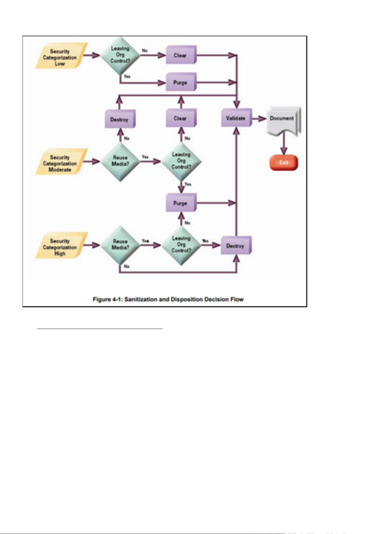
Cybersecurity recommended secure hardening guidelines
Securing the Network Management Module – 182
•
•
•
•
•
*Figure and data from NIST SP800-88
Embedded Flash Memory on Boards and Devices
Eaton recommends the following methods for disposing of motherboards, peripheral cards such as network adapters, or any
other adapter containing non-volatile flash memory.
Clear: If supported by the device, reset the state to original factory settings.
Navigate toSecuring the Network Management Module>>>Decommissioning the Network Management module.
Purge: If the flash memory can be easily identified and removed from the board, the flash memory may be destroyed
independently of the board that contained the flash memory. Otherwise, the whole board should be destroyed.
For the Network module thewhole board should be destroyed.
Destroy: Shred, disintegrate, pulverize, or Incinerate by burning the device in a licensed incinerator.
5.2.3 References
[R1] Cybersecurity Considerations for Electrical Distribution Systems (WP152002EN):http://www.eaton.com/ecm/groups/public/
@pub/@eaton/@corp/documents/content/pct_1603172.pdf
[R2] Cybersecurity Best Practices Checklist Reminder (WP910003EN):http://www.cooperindustries.com/content/dam/public/
powersystems/resources/library/1100_EAS/WP910003EN.pdf
[R3] NIST SP 800-82 Rev 2, Guide to Industrial Control Systems (ICS) Security, May 2015:https://nvlpubs.nist.gov/nistpubs/
SpecialPublications/NIST.SP.800-82r2.pdf
[R4] National Institute of Technology (NIST) Interagency “Guidelines on Firewalls and Firewall Policy, NIST Special Publication
800-41”, October 2009:http://nvlpubs.nist.gov/nistpubs/Legacy/SP/nistspecialpublication800-41r1.pdf
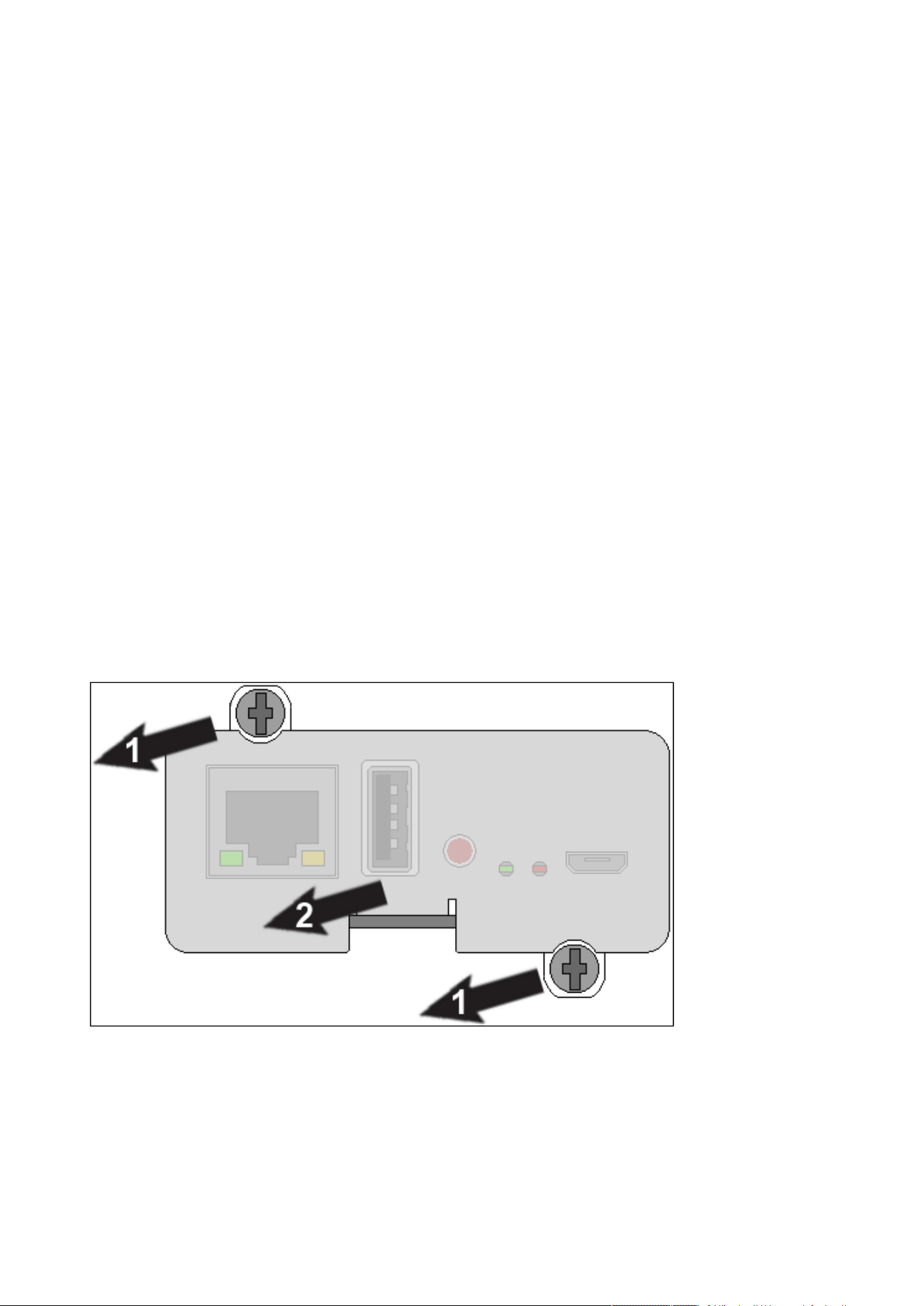
Configuring user permissions through profiles
Securing the Network Management Module – 183
[R5] NIST SP 800-88, Guidelines for Media Sanitization, September 2006:http://ws680.nist.gov/publication/get_pdf.cfm?
pub_id=50819
[R6] Cybersecurity Best Practices for Modern Vehicles - NHTSA:https://www.nhtsa.gov/staticfiles/nvs/pdf/
812333_CybersecurityForModernVehicles.pdf
[R7] A Summary of Cybersecurity Best Practices - Homeland Security:https://www.hsdl.org/?view&did=806518
[R8] Characterization of Potential Security Threats in Modern Automobiles - NHTSA:https://www.nhtsa.gov/DOT/NHTSA/NVS/
Crash%20Avoidance/Technical%20Publications/2014/812074_Characterization_PotentialThreatsAutos(1).pdf
[R9] Threat Modeling for Automotive Security Analysis:http://nvlpubs.nist.gov/nistpubs/Legacy/SP/
nistspecialpublication800-41r1.pdf
5.3 Configuring user permissions through profiles
The user profile can be defined when creating a new users or changed when modifying an existing one.
Refer to the sectionContextual help>>>Settings>>>Local usersin the settings.
5.4 Decommissioning the Network Management module
With the increased frequency of reported data breaches, it’s becoming more and more necessary for companies to implement
effective and reliable decommissioning policies and procedures.
In order to protect the data stored on retired IT equipment from falling into the wrong hands, or a data breach, we recommend to
follow below decommissioning steps:
1- Sanitize the Network Module
Sanitizationerases all the data (user name and password, certificates, keys, settings, logs...).
To sanitize the Network Module refer to theContextual help>>>Maintenance>>>Services>>>Sanitization section.
2- Unmount the Network Module from the device.
Unscrew the Network Module and remove it from the slot.
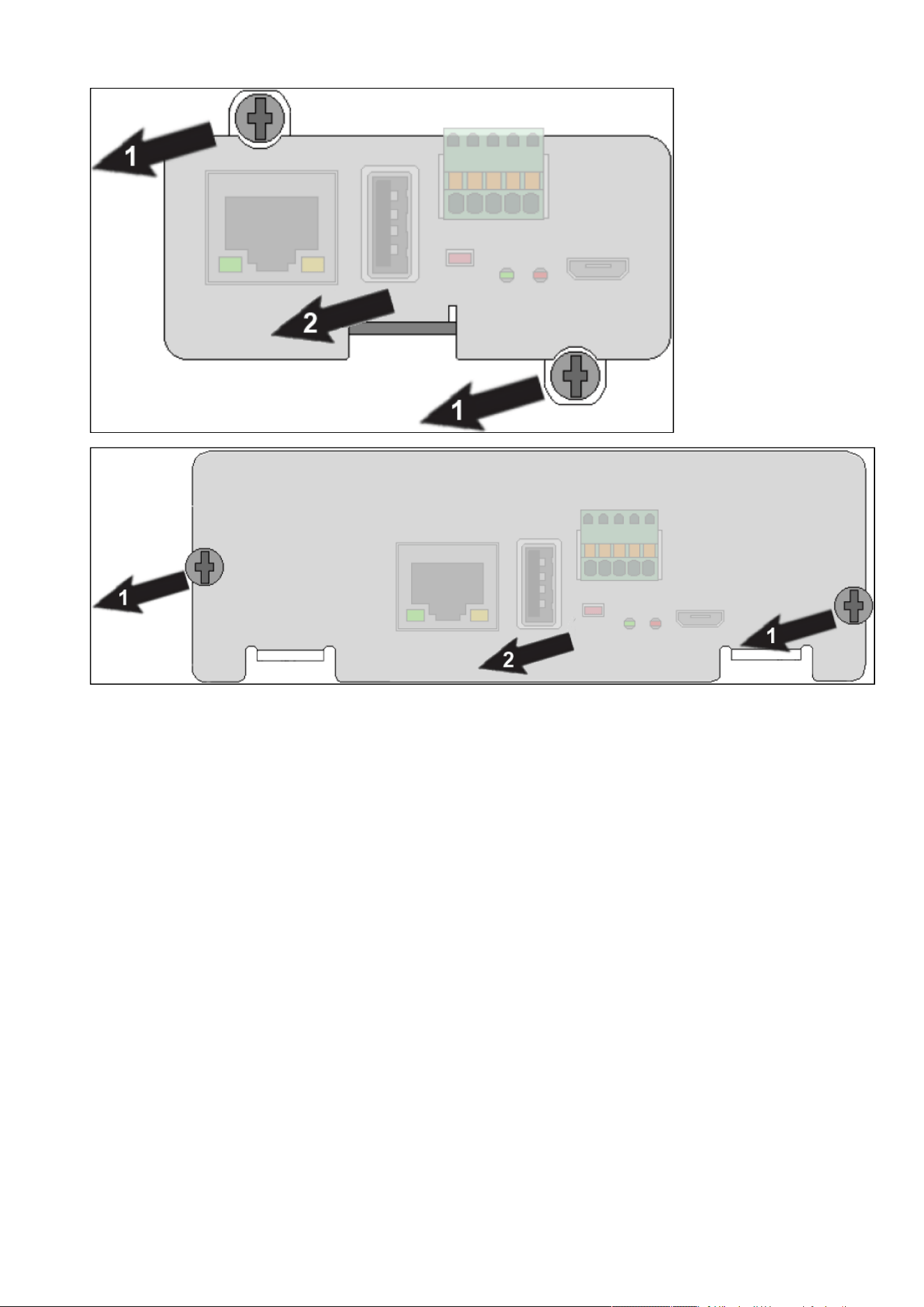
Decommissioning the Network Management module
Securing the Network Management Module – 184

Description and features
Servicing the EMP – 185
•
•
•
•
•
•
•
•
•
•
•
•
•
•
•
•
6 Servicing the EMP
6.1 Description and features
The optional Environmental Monitoring Probe EMPDT1H1C2 enables you to collect temperature and humidity readings and monitor
the environmental data remotely.
You can also collect and retrieve the status of one or two dry contact devices (not included).
Up to 3 Environmental Monitoring Probe can be daisy chained on one device.
You can monitor readings remotely using SNMP or a standard Web browser through the Network module.
This provides greater power management control and flexible monitoring options.
The EMP device is delivered with a screw and screw anchor, nylon fasteners, tie wraps, and magnets. You can install the device
anywhere on the rack or on the wall near the rack.
The EMP has the following features:
The hot-swap feature simplifies installation by enabling you to install the probe safely without turning off power to the device
or to the loads that are connected to it.
The EMP monitors temperature and humidity information to help you protect critical equipment.
The EMP measures temperatures from 0°C to 70°C with an accuracy of ±2°C.
The EMP measures relative humidity from 10% to 90% with an accuracy of ±5%.
The EMP can be located some distance away from the device with a CAT5 network cable up to 50m (165 ft) long.
The EMP monitors the status of the two user-provided contact devices.
Temperature, humidity, and contact closure status can be displayed through a Web browserthrough the Network module or
LCD interface (if available)
A Temperature and Humidity Offset can be set.
6.2 Unpacking the EMP
TheEMPDT1H1C2sensor will include the following:
Dry contact terminal block
Installation instructions
USB to RS485 converter
RJ45 female to female connector
Wall mounting screw and anchor
Rack mounting screw nut and washer
Tie wraps (x2)
Nylon fastener
For more information, refer to the device manual.
Packing materials must be disposed of in compliance with all local regulations concerning waste.
Recycling symbols are printed on the packing materials to facilitate sorting.
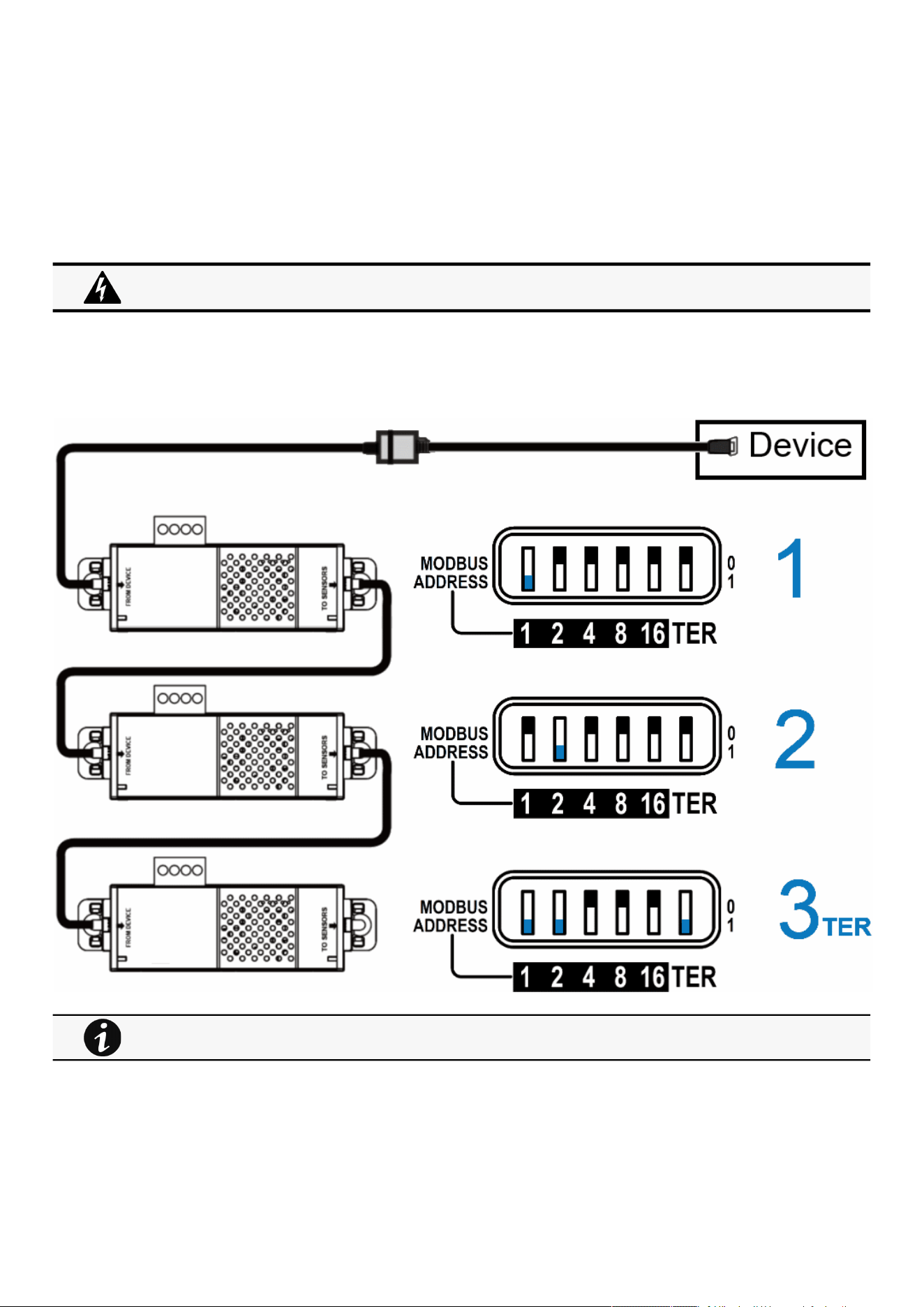
Installing the EMP
Servicing the EMP – 186
6.3 Installing the EMP
6.3.1 Defining EMPs address and termination
6.3.1.1 Manual addressing
Define different address for all the EMPs in the daisy-chain.
Set the RS485 termination (TER) to 1 on the last EMP of the daisy chain, set it to 0 on all the other EMPs.
6.3.1.1.1 Example:manual addressing of 3 EMPs connected to the Device
6.3.2 Mounting the EMP
The EMP includes magnets, cable ties slots and keyholes to enable multiple ways of mounting it on your installation.
Address must be defined before the EMP power-up otherwise the changes won't be taken into account.
Do not set Modbus address to 0,otherwise the EMP will not be detected.
Green LED of the TO DEVICE RJ45 connector shows if the EMP is powered by the Network module.
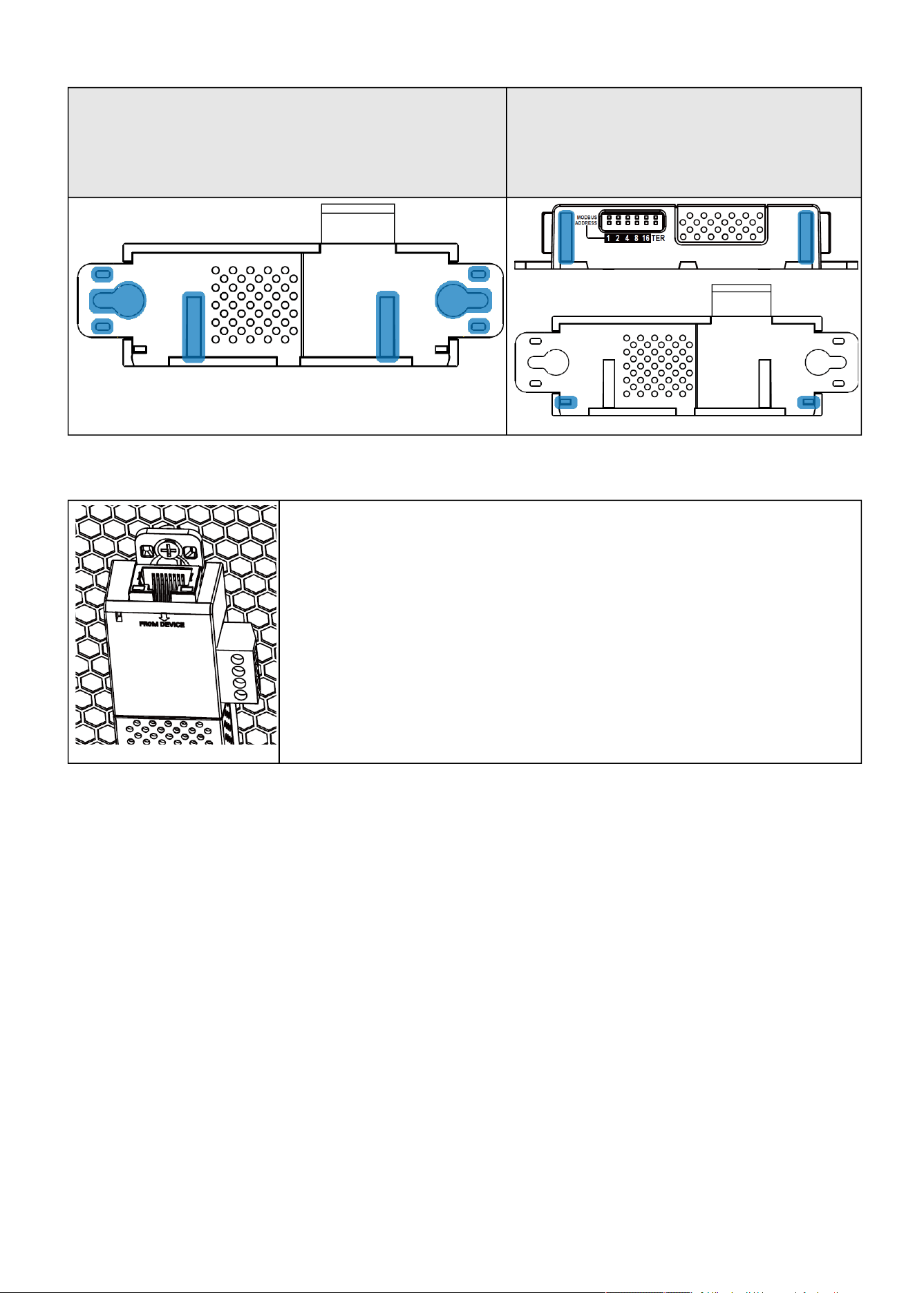
Installing the EMP
Servicing the EMP – 187
•
•
•
•
•
•
Bottom mounting capabilities:
magnets
keyholes
tie wraps
nylon fastener
Side
mounting:
magnets
tie wraps
6.3.2.1 Rack mounting with keyhole example
To mount the EMP on the rack, use the supplied screw, washer and nut. Then, mount the EMP on the
screw and tighten it.
6.3.2.2 Rack mounting with tie wraps example
To mount the EMP on the door of the rack, use the supplied cable ties.
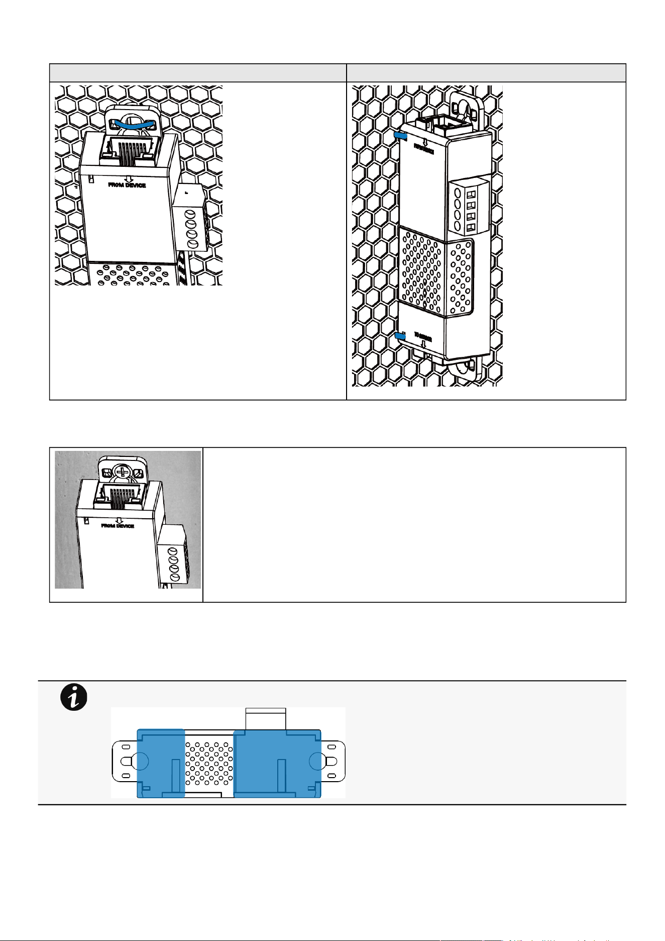
Installing the EMP
Servicing the EMP – 188
Bottom mounting Side mounting
6.3.2.3 Wall mounting with screws example
To mount the EMP on the wall close to the rack, use the supplied screw and screw anchor. Then, mount
the EMP on the screw and tighten it.
6.3.2.4 Wall mounting with nylon fastener example
To mount the EMP within the enclosure environment, attach one nylon fastener to the EMP and the other nylon fastener to an
enclosure rail post. Then, press the two nylon strips together to secure the EMP to the rail post.
Cut nylon fastener and stick it on the EMP bottom on the location highlighted below,this will prevent to interfere
with the EMP data acquisition parts.
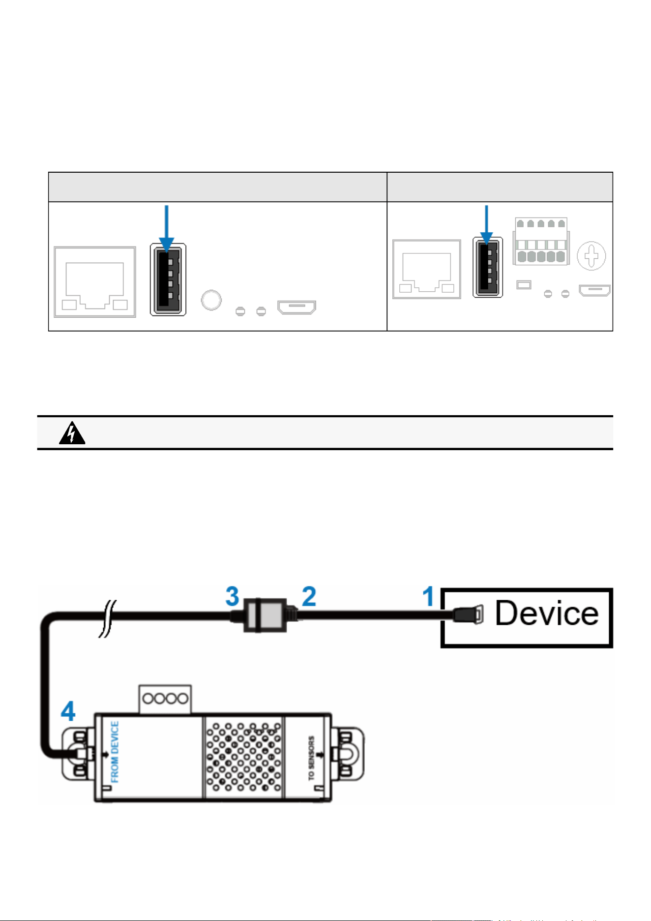
Installing the EMP
Servicing the EMP – 189
•
•
•
•
•
6.3.3 Cabling the first EMP to the device
6.3.3.1 Available Devices
6.3.3.1.1 Network-M2/INDGW
Network-M2 INDGW
Unable to render include or excerpt-include. Could not retrieve page.
6.3.3.2 Connecting the EMP to the device
6.3.3.2.1 Material needed:
EMP
RJ45 female/female connector (supplied in EMP accessories)
USB to RS485 converter cable(supplied in EMP accessories)
Ethernet cable (not supplied).
Device
6.3.3.2.2 Connection steps
STEP 1 – Connect the "USB to RS485 converter cable" to the USB port of the Device.
Address must be defined before the EMP power-up otherwise the changes won't be taken into account.
Do not set Modbus address to 0,otherwise the EMP will not be detected.
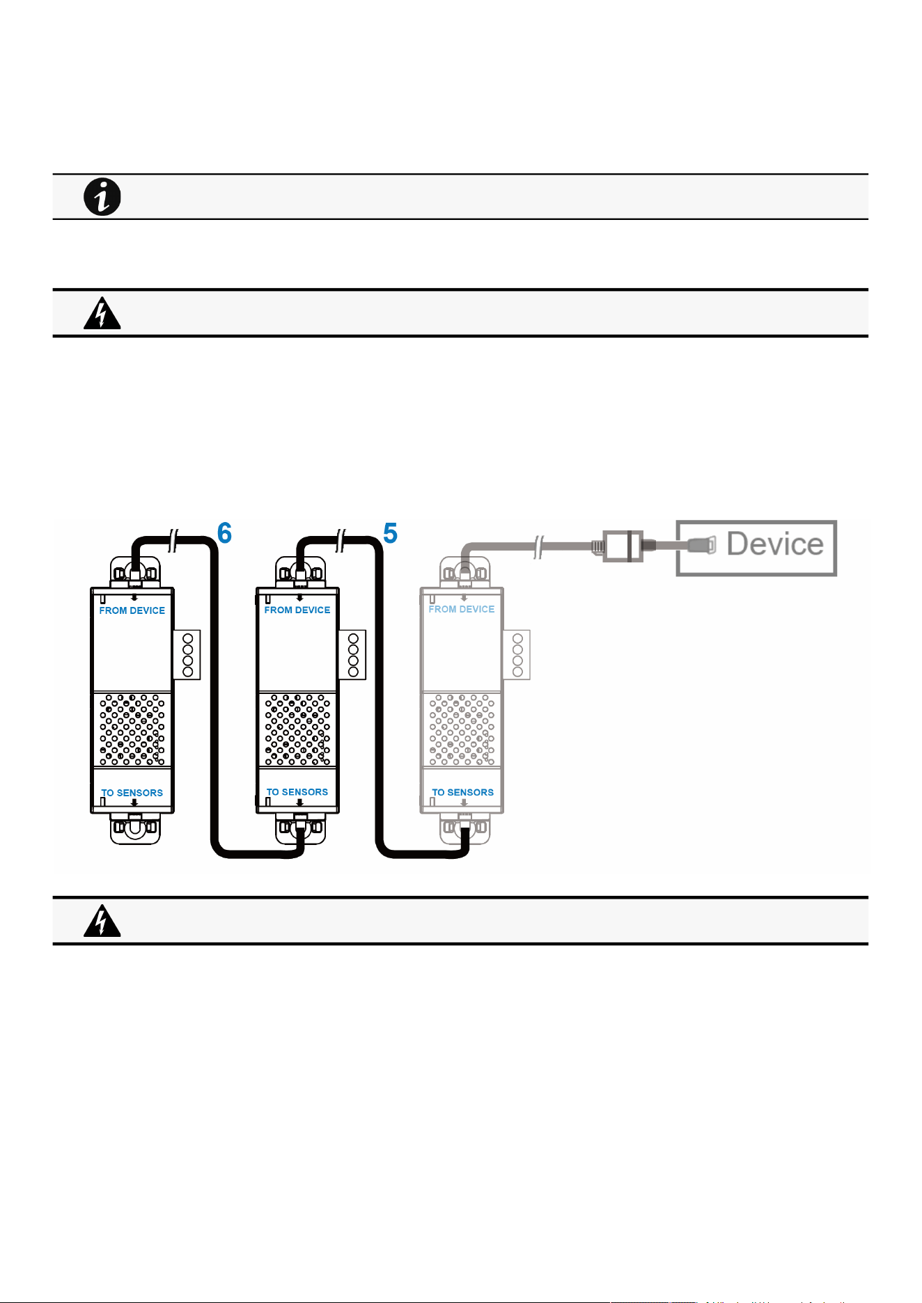
Installing the EMP
Servicing the EMP – 190
•
•
•
•
STEP 2 – Connect the "USB to RS485 converter cable" to the RJ45 female/female connector.
STEP 3 –Connect the Ethernet cableto theother end of the RJ45 female/female connector.
STEP 4–Connect the other end of the Ethernet cable to the RJ-45 port on the EMP (FROM DEVICE).
6.3.4 Daisy chaining EMPs
6.3.4.1 Material needed:
First EMP connected to the device (refer to previous section)
Additional EMPs
2 x Ethernet cable (not supplied).
Device
6.3.4.2 Steps
STEP 5–Connect the Ethernet cable to the "TO SENSORS" port of the first EMP, and to the "FROM DEVICE" port of the second
EMP.
STEP 6–Connect the Ethernet cable to the "TO SENSORS" port of the second EMP, and to the "FROM DEVICE" port of the third
EMP.
Use the supplied tie wraps to secure the "RS485 to USB cable" to the Network cable.
Address must be defined before EMP power-up; otherwise, the changes will not be applied.
Do not set Modbus address to 0;otherwise, the EMP will not be detected.
Up to 3 EMP can be daisy chained on one device.
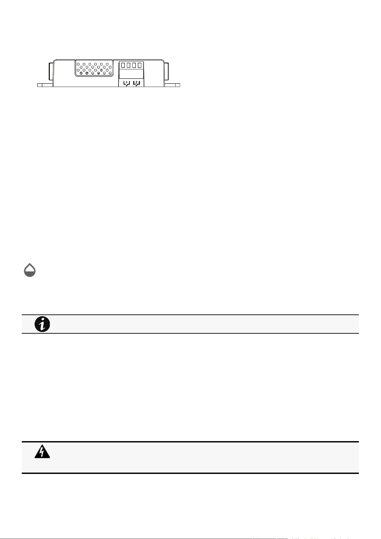
Commissioning the EMP
Servicing the EMP – 191
•
•
•
•
•
•
•
•
•
•
•
•
•
•
6.3.5 Connecting an external contact device
To connect an external device to the EMP:
STEP 1 –Connect the external contact closure inputs to the terminal block on the EMP (see the table and the figure below):
External contact device 1. Connect the return and signal input wires from device 1 to screw terminals 1.
External contact device 2. Connect the return and signal input wires from device 2 to screw terminals 2.
STEP 2 –Tighten the corresponding tightening screws on top of the EMP to secure the wires.
6.4 Commissioning the EMP
6.4.1 On the Network Module device
STEP 1–Connect to the Network Module
On a network computer, launch a supported web browser. The browser window appears.
In the Address/Location field, enter:https://xxx.xxx.xxx.xxx/where xxx.xxx.xxx.xxx is the IP address of the Network Module.
The log in screen appears.
Enter the user name in the User Name field.
Enter the password in the Password field.
ClickLogin. The Network Module web interface appears.
STEP 2–Navigate to Environment menu:
STEP 3–Proceed to the commissioning, refer to the contextual help for details:Contextual
help>>>Environment>>>Commissioning/Status
ClickDiscover. The EMP connected to the Network module appears in the table.
Press the pen logoto edit EMP information and access its settings.
ClickDefine offsetsto define temperature or humidity offsets if needed.
STEP 4–Define alarm configuration, refer to the contextual help for details:Contextual help>>>Environment>>>Alarm
configuration
Select theAlarm configurationpage.
Enable or disable alarms.
Define thresholds, hysteresis and severity of temperature, humidity and dry contacts alarms.
6.5 Using the EMP for temperature compensated battery charging
This section applies only to UPS that provides temperature compensated battery charging option.
When discovered, the orange LEDs of the EMP RJ45 connectors shows the data traffic.
If the discovery process fails refer to the troubleshooting section.
Address must be defined before EMP power-up; otherwise, the changes will not be applied.
Do not set Modbus address to 0;otherwise, the EMP will not be detected.
Definea unique addressfor all the EMPs in the daisy-chain.
Set the RS485 termination (TER) to 1 on the last EMP of the daisy chain. On other EMPs this should be set to 0.
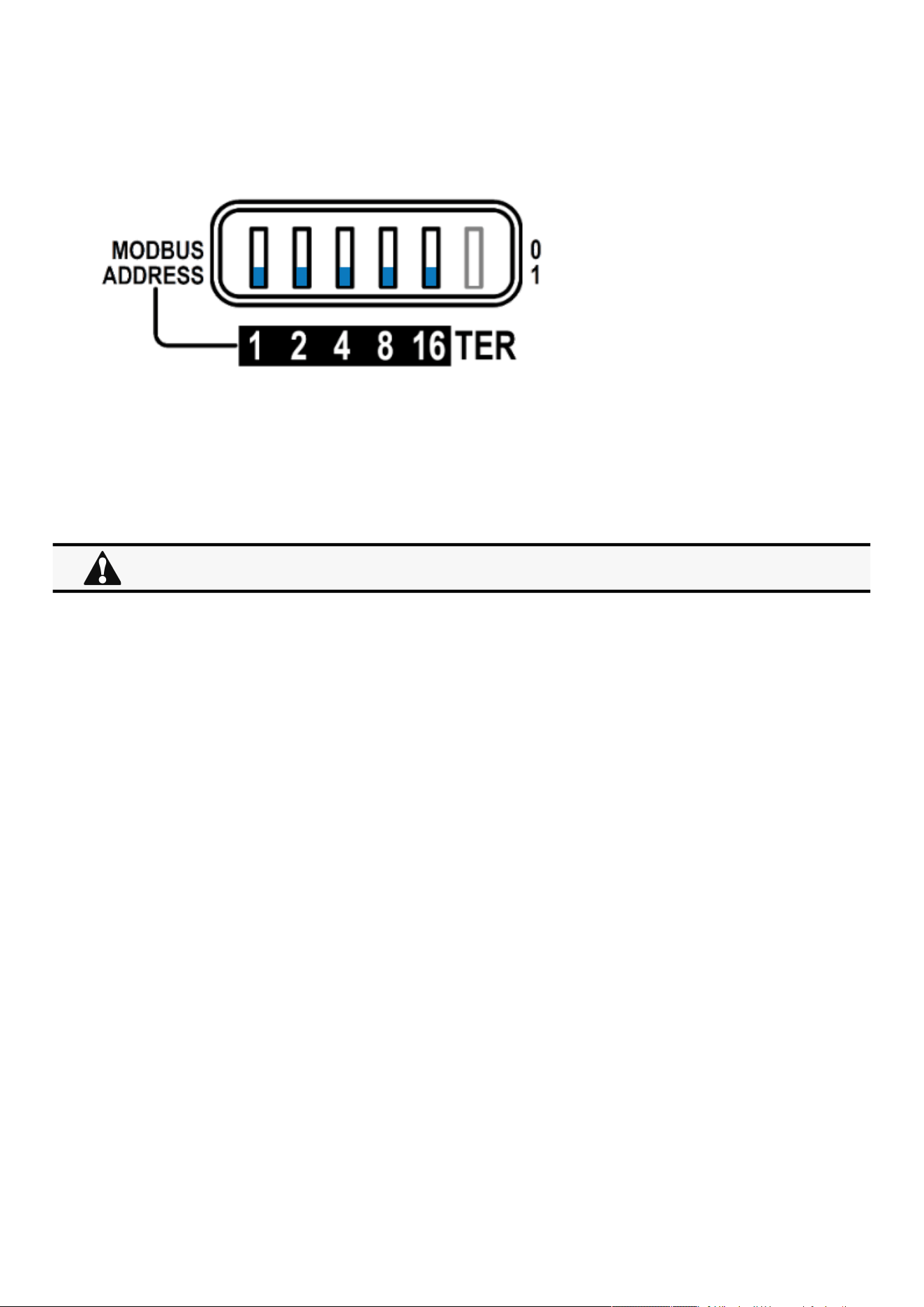
Using the EMP for temperature compensated battery charging
Servicing the EMP – 192
•
6.5.1 Addressing the EMP
Set the address 31 to the sensor dedicated to the battery room temperature:
Set all the Modbus address switches to 1 to set the EMP to the address 31 as indicated on the picture below:
6.5.2 Commissioning the EMP
Refer to thesectionContextual help>>>Environment>>>Commissioning/Status.
6.5.3 Enabling temperature compensated battery charging in the UPS
To enablethe temperature compensated battery charging, refer to the UPS user manual.
The temperature compensated battery charging feature needs to be enabled in the UPS.
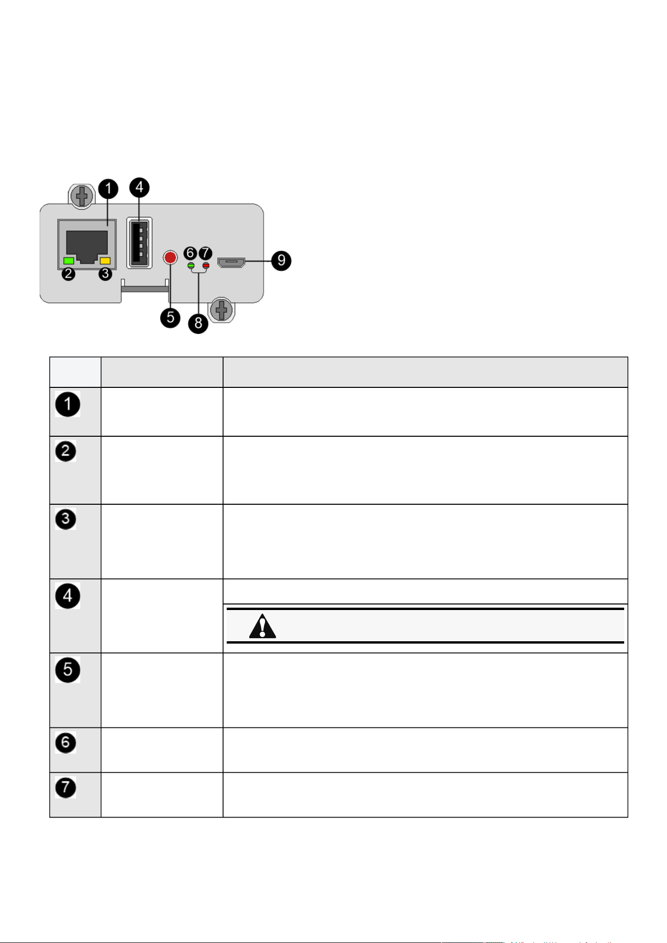
Front panel connectors and LED indicators
Information – 193
•
•
•
•
•
•
•
•
7 Information
7.1 Front panel connectors and LED indicators
Nbr Name Description
Network connector Ethernet port
Network speed LED Flashing green sequences:
1 flash — Port operating at 10Mbps
2 flashes — Port operating at 100Mbps
3 flashes — Port operating at 1Gbps
Network link/activity LED
Off— UPS Network Module is not connected to the network.
Solid yellow— UPS Network Module is connected to the network, but no activity
detected.
Flashing yellow— UPS Network Module is connected to the network and sending
or receiving data.
AUX connector For Network Module accessories only.
Restart button Ball point pen or equivalent will be needed to restart:
Short press (<6s)— Safe software restart (firmware safely shutdown before
restart).
Long press (>9s)— Forced hardware restart.
ON LED Flashing green— Network Module is operating normally.
Warning LED Solid red— Network Module is in error state.
Do not use for general power supply or USB charger.
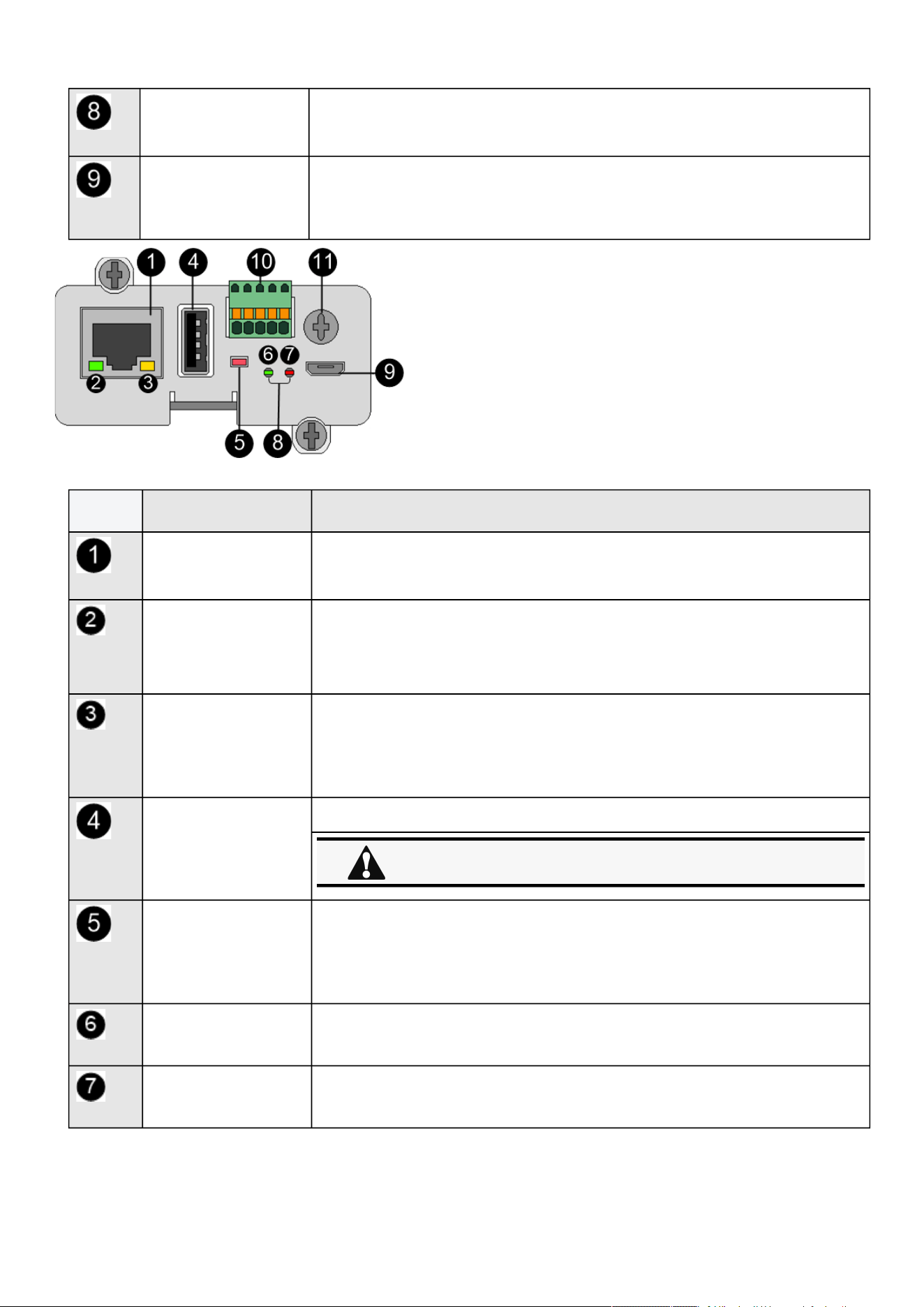
Front panel connectors and LED indicators
Information – 194
•
•
•
•
•
•
•
•
Boot LEDs Solid green and flashing red— Network Module is starting boot sequence.
Settings/UPS data
connector
Configuration port.
Access to Network Module’s web interface through RNDIS (Emulated Network port).
Access to the Network Module console through Serial (Emulated Serial port).
Nbr Name Description
Network connector Ethernet port
Network speed LED Flashing green sequences:
1 flash — Port operating at 10Mbps
2 flashes — Port operating at 100Mbps
3 flashes — Port operating at 1Gbps
Network link/activity LED
Off— UPS Network Module is not connected to the network.
Solid yellow— UPS Network Module is connected to the network, but no activity
detected.
Flashing yellow— UPS Network Module is connected to the network and sending
or receiving data.
AUX connector For Network Module accessories only.
Restart button Ball point pen or equivalent will be needed to restart:
Short press (<6s)— Safe software restart (firmware safely shutdown before
restart).
Long press (>9s)— Forced hardware restart.
ON LED Flashing green— Network Module is operating normally.
Warning LED Solid red— Network Module is in error state.
Do not use for general power supply or USB charger.
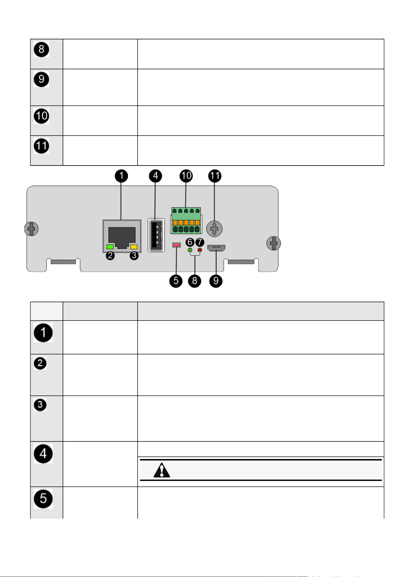
Front panel connectors and LED indicators
Information – 195
•
•
•
•
•
•
•
Boot LEDs Solid green and flashing red— Network Module is starting boot sequence.
Settings/UPS data connector Configuration port.
Access to Network Module’s web interface through RNDIS (Emulated Network port).
Access to the Network Module console through Serial (Emulated Serial port).
Modbus connector Detachable terminal block with push-in connections: 0V / T+ / T- / R+ / R-
Shield Depending on the cabling this location may be used as a shield reference.
Nbr Name Description
Network connector Ethernet port
Network speed LED Flashing green sequences:
1 flash — Port operating at 10Mbps
2 flashes — Port operating at 100Mbps
3 flashes — Port operating at 1Gbps
Network link/activity LED
Off— UPS Network Module is not connected to the network.
Solid yellow— UPS Network Module is connected to the network, but no activity
detected.
Flashing yellow— UPS Network Module is connected to the network and sending
or receiving data.
AUX connector For Network Module accessories only.
Restart button Ball point pen or equivalent will be needed to restart:
Short press (<6s)— Safe software restart (firmware safely shutdown before
restart).
Do not use for general power supply or USB charger.
Specifications/Technical characteristics
Information – 196
• Long press (>9s)— Forced hardware restart.
ON LED Flashing green— Network Module is operating normally.
Warning LED Solid red— Network Module is in error state.
Boot LEDs Solid green and flashing red— Network Module is starting boot sequence.
Settings/UPS data connector Configuration port.
Access to Network Module’s web interface through RNDIS (Emulated Network port).
Access to the Network Module console through Serial (Emulated Serial port).
Modbus connector Detachable terminal block with push-in connections: 0V / T+ / T- / R+ / R-
Shield Depending on the cabling this location may be used as a shield reference.
7.2 Specifications/Technical characteristics
Physical characteristics
Dimensions (wxdxh) 132 x 66 x 42 mm | 5.2 x 2.6 x 1.65 in
Weight 70 g | 0.15 lb
RoHS 100% compatible
Storage
Storage temperature -25°C to 70°C (14°F to 158°F)
Ambient conditions
Operating temperature 0°C to 70°C (32°F to 158°F)
Relative humidity 5%-95%, noncondensing
Module performance
Module input power 5V-12V ±5% | 1A
AUX output power 5V ±5% | 200mA
Date/Time backup CR1220 battery coin cell | The RTC is able to keep the date and the
time when Network Module is OFF
Functions
Languages English, French, German, Italian, Japanese, Russian, Simplified
Chinese, Spanish, Traditional Chinese

Default settings and possible parameters
Information – 197
Functions
Alarms/Log Email, SNMP trap, web interface / Log on events
Network Gigabit ETHERNET, 10/100/1000Mb/s, auto negotiation, HTTP 1.1,
SNMP V1, SNMP V3, NTP, SMTP, DHCP
Security Restricted to TLS 1.2
Supported MIBs
xUPS MIB | Standard IETF UPS MIB (RFC 1628) | Sensor MIB
Browsers Google Chrome, Firefox, Safari
Settings (default values)
IP network DHCP enabled | NTP server: pool.ntp.org
Port 443 (https), 22 (ssh), 161 (snmp), 162 (snmp trap), 25 (smtp), 8883
(mqtts), 123 (ntp), 5353 (mdns-sd), 80 (http), 514 (syslog),636 (LDAP),
1812 (RADIUS)
Web interface access
control
User name: admin | Password: admin
Settings/Device data
connector
USB RNDIS Apipa compatible | IP address: 169.254.0.1 | Subnet mask:
255.255.0.0
7.3 Default settings and possible parameters
7.3.1 Meters
Default settings and possible parameters - Meters
Default setting Possible parameters
Meters/Logs Log measures every—60s Log measures every — 3600s maximum
7.3.2 Settings
Default settings and possible parameters - General
Default setting Possible parameters

Default settings and possible parameters
Information – 198
•
•
System details Location—empty
Contact—empty
System name—empty
Time & date settings—Manual (Time zone:
Europe/Paris)
Location — 31 characters maximum
Contact— 255 characters maximum
System name— 255 characters maximum
Time & date settings—Manual (Time zone: selection
on map/Date) / Dynamic (NTP)
Email notification settings No email 5 configurations maximum
Custom name — 128 characters maximum
Email address — 128 characters maximum
Hide IP address from the email body — enable/
disabled
Status — Active/Inactive
Alarm notifications
Active — No/Yes
All card events – Subscribe/Attach logs
Critical alarm – Subscribe/Attach logs
Warning alarm – Subscribe/Attach logs
Info alarm – Subscribe/Attach logs
All device events – Subscribe/Attach
measures/Attach logs
Critical alarm – Subscribe/Attach measures
/Attach logs
Warning alarm – Subscribe/Attach
measures/Attach logs
Info alarm – Subscribe/Attach measures/
Attach logs
Always notify events with code
Never notify events with code
Schedule report
Active — No/Yes
Recurrence – Every day/Every week/Every
month
Starting – Date and time
Card events – Subscribe/Attach logs
Device events – Subscribe/Attach
measures/Attach logs
SMTP settings Server IP/Hostname — blank
SMTP server authentication — disabled
Port — 25
Default sender address —
device
@networkcard.com
Hide IP address from the email body — disabled
Secure SMTP connection — enabled
Verify certificate authority — disabled
SMTP server authentication — disabled
Server IP/Hostname — 128 characters maximum
SMTP server authentication — disable/enable
(Username/Password — 128 characters maximum)
Port — x-xxx
Sender address — 128 characters maximum
Hide IP address from the email body — enable/
disabled
Secure SMTP connection — enable/disable
Verify certificate authority — disable/enable
Default settings and possible parameters - Global user settings and Local users

Default settings and possible parameters
Information – 199
•
•
•
•
•
•
•
•
•
•
•
•
•
•
•
•
•
•
•
•
•
•
•
•
Default setting Possible parameters
Password settings Minimum length — enabled (8)
Minimum upper case — enabled (1)
Minimum lower case — enabled (1)
Minimum digit — enabled (1)
Special character — enabled (1)
Minimum length — enable (6-32)/disable
Minimum upper case — enable (0-32)/disable
Minimum lower case — enable (0-32)/disable
Minimum digit — enable (0-32)/disable
Special character — enable (0-32)/disable
Password expiration Number of days until password expires — disabled
Main administrator password never expires —
disabled
Number of days until password expires — disable/
enable (1-99999)
Main administrator password never expires —
disable/enable
Lock account Lock account after xx invalid tries — disabled
Main administrator account never blocks — disabled
Lock account after xx invalid tries — disable/enable
(1-99)
Main administrator account never blocks — disable/
enable
Account timeout No activity timeout — 60 minutes
Session lease time — 120 minutes
No activity timeout — 1-60 minutes
Session lease time — 60-720 minutes
Local users 1 user only:
Active—Yes
Profile—Administrator
Username—admin
Full Name—blank
Email—blank
Phone—blank
Organization—blank
20 users maximum:
Active—Yes/No
Profile—Administrator/Operator/Viewer
Username—255 characters maximum
Full Name—128 characters maximum
Email—128 characters maximum
Phone—64 characters maximum
Organization—128 characters maximum
Default settings and possible parameters - Remote users
Default setting Possible parameters
LDAP Configure
Active – No
Security
SSL – SSL
Verify server certificate – enabled
Primary server
Name – Primary
Hostname – blank
Port – 636
Secondary server
Name – blank
Hostname – blank
Port – blank
Credentials
Anonymous search bind – disabled
Search user DN – blank
Password – blank
Configure
Active – No/yes
Security
SSL – None/Start TLS/SSL
Verify server certificate – disabled/enabled
Primary server
Name – 128 characters maximum
Hostname – 128 characters maximum
Port – x-xxx
Secondary server
Name – 128 characters maximum
Hostname – 128 characters maximum
Port – x-xxx
Credentials
Anonymous search bind – disabled/
enabled
Search user DN – 1024 characters

Default settings and possible parameters
Information – 200
•
•
•
•
•
•
•
•
•
•
•
•
•
•
•
•
•
•
•
•
•
•
•
•
•
•
•
•
Search base
Search base DN – dc=example,dc=com
Request parameters
User base DN –
ou=people,dc=example,dc=com
User name attribute – uid
UID attribute – uidNumber
Group base DN –
ou=group,dc=example,dc=com
Group name attribute – gid
GID attribute – gidNumber
Profile mapping – no mapping
Users preferences
Language –
English
Temperature unit – °C (Celsius)
Date format – MM-DD-YYYY
Time format – hh:mm:ss (24h)
maximum
Password – 128 characters maximum
Search base
Search base DN – 1024 characters
maximum
Request parameters
User base DN – 1024 characters
maximum
User name attribute – 1024 characters
maximum
UID attribute – 1024 characters maximum
Group base DN – 1024 characters
maximum
Group name attribute – 1024 characters
maximum
GID attribute – 1024 characters maximum
Profile mapping – up to 5 remote groups mapped to
local profiles
Users preferences
Language – English, French, German,
Italian, Japanese, Russian, Simplified
Chinese, Spanish, Traditional Chinese
Temperature unit – °C (Celsius)/°F
(Fahrenheit)
Date format – MM-DD-YYYY / YYY-MM-
DD / DD-MM-YYY / DD.MM.YYY / DD/
MM/YYY / DD MM YYYY
Time format – hh:mm:ss (24h) / hh:mm:ss
(12h)
RADIUS Configure
Active – No
Retry number – 0
Primary server
Name – blank
Secret – blank
Address – blank
UDP port – 1812
Time out – 3
Secondary server
Name – blank
Secret – blank
Address – blank
UDP port – 1812
Time out – 3
Users preferences
Language –
English
Temperature unit – °C (Celsius)
Date format – MM-DD-YYYY
Time format – hh:mm:ss (24h)
Configure
Active – Yes/No
Retry number – 0 to 128
Primary server
Name – 128 characters maximum
Address – 128 characters maximum
Secret – 128 characters maximum
UDP port – 1 to 65535
Time out – 3 to 60
Secondary server
Name – 128 characters maximum
Address – 128 characters maximum
Secret – 128 characters maximum
UDP port – 1 to 65535
Time out – 3 to 60
Users preferences
Language – English, French, German,
Italian, Japanese, Russian, Simplified
Chinese, Spanish, Traditional Chinese
Temperature unit – °C (Celsius)
Date format – MM-DD-YYYY
Time format – hh:mm:ss (24h)

Default settings and possible parameters
Information – 201
•
•
•
•
Default settings and possible parameters - Network & Protocol
Default setting Possible parameters
IPV4 Mode — DHCP Mode — DHCP/Manual (Address/Netmask/Gateway)
IPV6 Enable — checked
Mode — DHCP
Enabled — Active/Inactive
Mode — DHCP/Manual (Address/Prefix/Gateway)
DNS/DHCP Hostname —
device
-[MAC address]
Mode — DHCP
Hostname — 128 characters maximum
Mode :DHCP/Manual (Domain name/Primary DNS/
Secondary DNS)
Ethernet Configuration — Auto negotiation Configuration — Auto negotiation - 10Mbps -Half
duplex - 10Mbps -Full duplex - 100Mbps - Half
duplex - 100Mbps -Full duplex - 1.0 Gbps - Full
duplex
HTTPS Port — 443
Disable Port 80 (http) - Not disabled
Port — x-xxx
Disable Port 80 (http) - Disabled
Syslog Inactive
Server#1
Name – Primary
Status – Disabled
Hostname – empty
Port – 514
Protocol – UDP
Message transfer method – Non transparent
framing
Using unicode byte order mask (BOM)–
disabled
Server#2
Name – empty
Status – Disabled
Hostname – empty
Port – 514
Protocol – UDP
Message transfer method – DIsabled in UDP
Using unicode byte order mask (BOM)–
disabled
Inactive/Active
Server#1
Name – 128 characters maximum
Status – Disabled/Enabled
Hostname – 128 characters maximum
Port – x-xxx
Protocol – UDP/TCP
Message transfer method – Non transparent
framing
Using unicode byte order mask (BOM)–
disable/enable
Server#2
Name – 128 characters maximum
Status – Disabled/Enabled
Hostname – 128 characters maximum
Port – x-xxx
Protocol – UDP/TCP
Message transfer method (in TCP)– Octet
counting/Non transparent framing
Using unicode byte order mask (BOM)–
disable/enable
Default settings and possible parameters - SNMP

Default settings and possible parameters
Information – 202
•
•
•
•
•
•
•
•
Default setting Possible parameters
SNMP Activate SNMP — disabled
Port — 161
SNMP V1 — disabled
Community #1 — public
Enabled — Inactive
Access — Read only
Community #2 — private
Enabled — Inactive
Access — Read/Write
SNMP V3 — enabled
User #1 — readonly
Enabled — Inactive
Access — Read only
Authentication — Auth (SHA-1)
Password — empty
Confirm password — empty
Privacy — Secured - AES
Key — empty
Confirm key — empty
User#2 — readwrite
Enabled — Inactive
Access — Read/Write
Authentication — Auth (SHA-1)
Password — empty
Confirmpassword — empty
Privacy — Secured - AES
Key — empty
Confirm key — empty
Activate SNMP — disable/enable
Port — x-xxx
SNMP V1 — disable/enable
Community #1 — 128 characters
maximum
Enabled — Inactive/Active
Access — Read only
Community #2 — 128 characters
maximum
Enabled — Inactive/Active
Access — Read/Write
SNMP V3 — disable/enable
User #1 — 32 characters maximum
Enabled — Inactive/Active
Access — Read only/Read-Write
Authentication — Auth (SHA-1)/None
Password — 128 characters maximum
Confirm password — 128 characters
maximum
Privacy — Secured - AES/None
Key — 128 characters maximum
Confirm key — 128 characters maximum
User#2 — 32 characters maximum
Enabled — Inactive/Active
Access — Read only/Read-Write
Authentication — Auth (SHA-1)/None
Password — 128 characters maximum
Confirmpassword — 128 characters
maximum
Privacy — Secured - AES/None
Key — 128 characters maximum
Confirm key — 128 characters maximum
Trap receivers No trap Enabled — No/Yes
Application name — 128 characters maximum
Hostname or IP address — 128 characters maximum
Port — x-xxx
Protocol — V1
Trap community — 128 characters maximum
Default settings and possible parameters - Industrial protocols
Default setting Possible parameters

Default settings and possible parameters
Information – 203
Modbus RTU Modbus RTU — Inactive
Baud rate (bps) — 19200
Parity — Even
Stop bits – 1
Modbus RTU — Inactive/Active
Baud rate (bps) —
1200/2400/4800/9600/19200/38400/57600/1152
00
Parity — None/Even/Odd
Stop bits – 1/2
Default setting Possible parameters
Modbus TCP Modbus TCP — Inactive
Port — 502
Modbus TCP — Inactive/Active
Port — x-xxx
Default setting Possible parameters
Mapping configuration No mapping Custom name – 128 characters maximum
Map – Eaton ModbusMS compatible, Eaton
PowerXpert UID 0 compatible, Card System
Information
Transport – RTU/TCP
Access – None/Read only/Read/Write
Illegal read behaviour – Return exception/Return
zeros
IP filtering – IP address
Coil/register base address shift – No shift/Shift
by 1 (JBUS)
Default setting Possible parameters
BACnet BACnet IP — Inactive BACnet IP — Inactive/Active
Device Id — Automatically generated, must be
unique, 4194304 characters maximum
Device Name — Automatically generated, must
be unique, 1-255 characters maximum, only Latin
letters, numbers, spaces, '_' and '!' symbols
Device connection control password — 6-20
characters maximum
Local port — 1-65535 characters maximum (as
all the other UDP and TCP ports)
MAC address — MAC address format
Broadcast management device — Inactive/Active
BBMD BACnet/IP device — IP address format
BBMD Time to live — 30-1800 seconds
Default settings and possible parameters - Certificate
Default setting Possible parameters

Default settings and possible parameters
Information – 204
•
•
•
•
Local certificates
Common name — Service + Hostname + selfsigned
Country — FR
State or Province — 38
City or Locality — Grenoble
Organization name — Eaton
Organization unit — Power quality
Contact email address — blank
Common name — 64 characters maximum
Country — Country code
State or Province —64 characters maximum
City or Locality —64 characters maximum
Organization name —64 characters maximum
Organization unit —64 characters maximum
Contact email address —64 characters maximum
7.3.3 Sensors alarm configuration
Default settings and possible parameters - Environment Alarm configuration
Default setting Possible parameters
Temperature Enabled—No
Low critical – 0°C/32°F
Low warning – 10°C/50°F
High warning – 70°C/158°F
High critical – 80°C/176°F
Enabled—No/Yes
low critical<low warning<high warning<high critical
Humidity Enabled—No
Low critical – 10%
Low warning – 20%
High warning – 80%
High critical – 90%
Enabled—No/Yes
0%<low critical<low warning<high warning<high
critical<100%
Dry contacts Enabled—No
Alarm severity – Warning
Enabled—No/Yes
Alarm severity – Info/Warning/Critical
7.3.4 User profile
Default settings and possible parameters - User profile
Default setting Possible parameters
Profile Account details:
Full name — Administrator
Email — blank
Account details:
Full name — 128 characters maximum
Email — 128 characters maximum

Default settings and possible parameters
Information – 205
•
•
•
•
•
•
•
•
•
•
•
•
Phone — blank
Organization — blank
Preferences:
Language —
English
Date format — MM-DD-YYYY
Time format — hh:mm:ss (24h)
Temperature — °C (Celsius)
Phone — 64 characters maximum
Organization — 128 characters maximum
Preferences:
Language — English, French, German,
Italian, Japanese, Russian, Simplified
Chinese, Spanish, Traditional Chinese
Date format — MM-DD-YYYY / YYY-MM-
DD / DD-MM-YYY / DD.MM.YYY / DD/
MM/YYY / DD MM YYYY
Time format — hh:mm:ss (24h) /
hh:mm:ss (12h)
Temperature — °C (Celsius)/°F
(Fahrenheit)
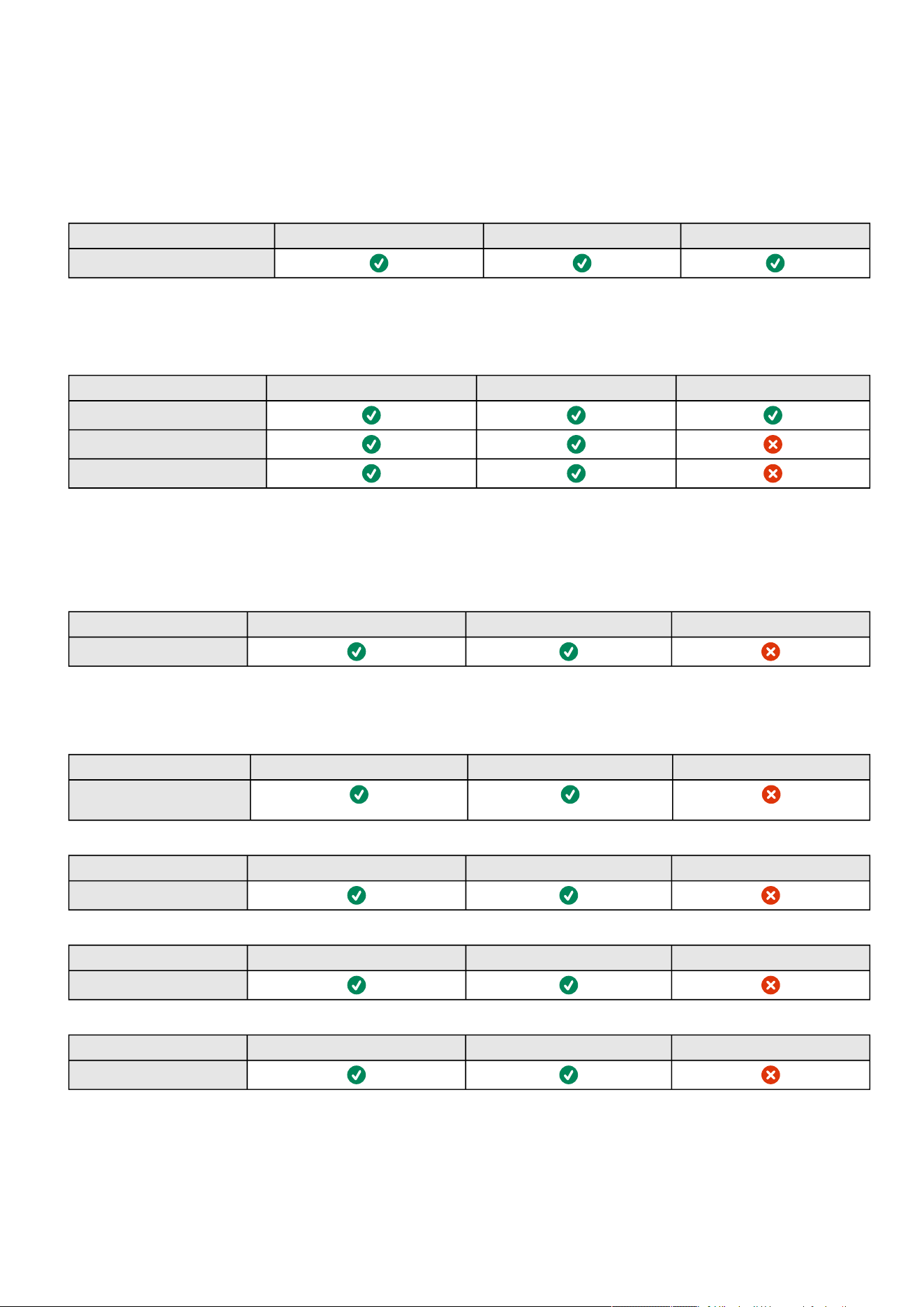
Access rights per profiles
Information – 206
7.4 Access rights per profiles
7.4.1 Home
Administrator Operator Viewer
Home
7.4.2 Meters
Administrator Operator Viewer
Meters
Battery health: Launch test/Abort
Logs configuration
7.4.3 Controls
Administrator Operator Viewer
Control
7.4.4 Protection
Administrator Operator Viewer
Protection/Scheduled
shutdowns
Administrator Operator Viewer
Protection/Agent list
Administrator Operator Viewer
Protection/Agent settings
Administrator Operator Viewer
Protection/Sequence
7.4.5 Environment
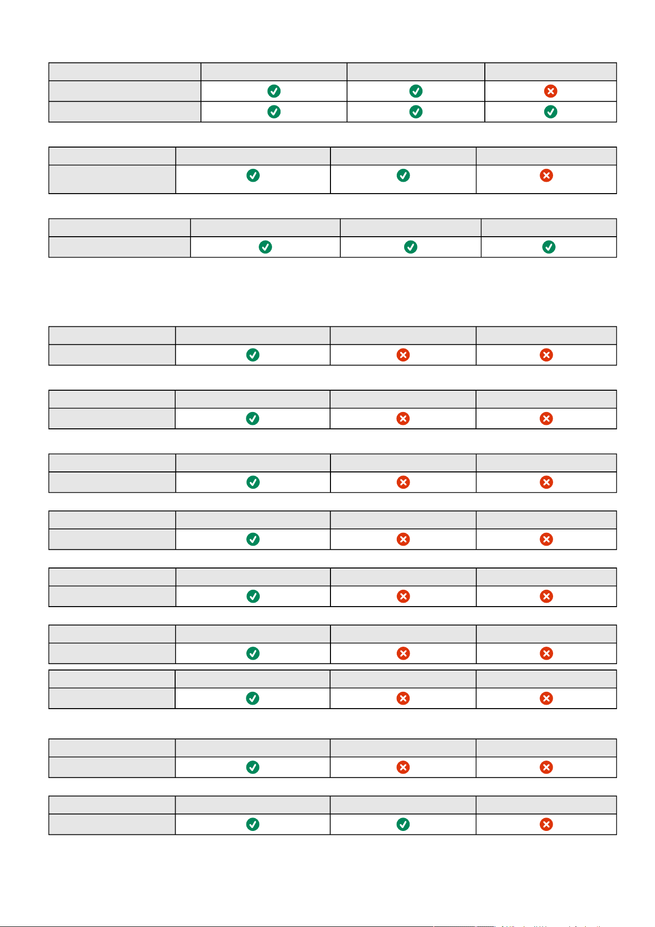
Access rights per profiles
Information – 207
Administrator Operator Viewer
Environment/Commissioning
Environment/Status
Administrator Operator Viewer
Environment/Alarm
configuration
Administrator Operator Viewer
Environment/Information
7.4.6 Settings
Administrator Operator Viewer
General
Administrator Operator Viewer
Local users
Administrator Operator Viewer
Remote users
Administrator Operator Viewer
Network & Protocols
Administrator Operator Viewer
SNMP
Administrator Operator Viewer
Industrial protocols/Modbus*
Administrator Operator Viewer
Industrial protocols/BACnet*
*for INDGW only
Administrator Operator Viewer
Certificate
Administrator Operator Viewer
ATS
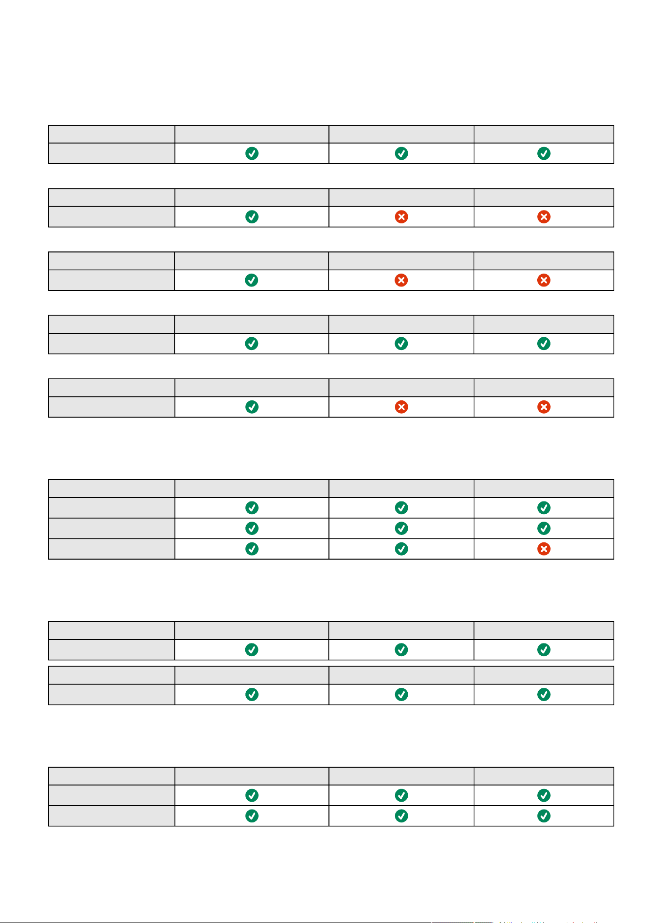
Access rights per profiles
Information – 208
7.4.7 Maintenance
Administrator Operator Viewer
System information
Administrator Operator Viewer
Firmware
Administrator Operator Viewer
Services
Administrator Operator Viewer
Resources
Administrator Operator Viewer
System logs
7.4.8 Alarms
Administrator Operator Viewer
Alarm list
Export
Clear
7.4.9 User profile
Administrator Operator Viewer
User profile
Administrator Operator Viewer
Legal information
7.4.10 Contextual help
Administrator Operator Viewer
Contextual help
Full documentation
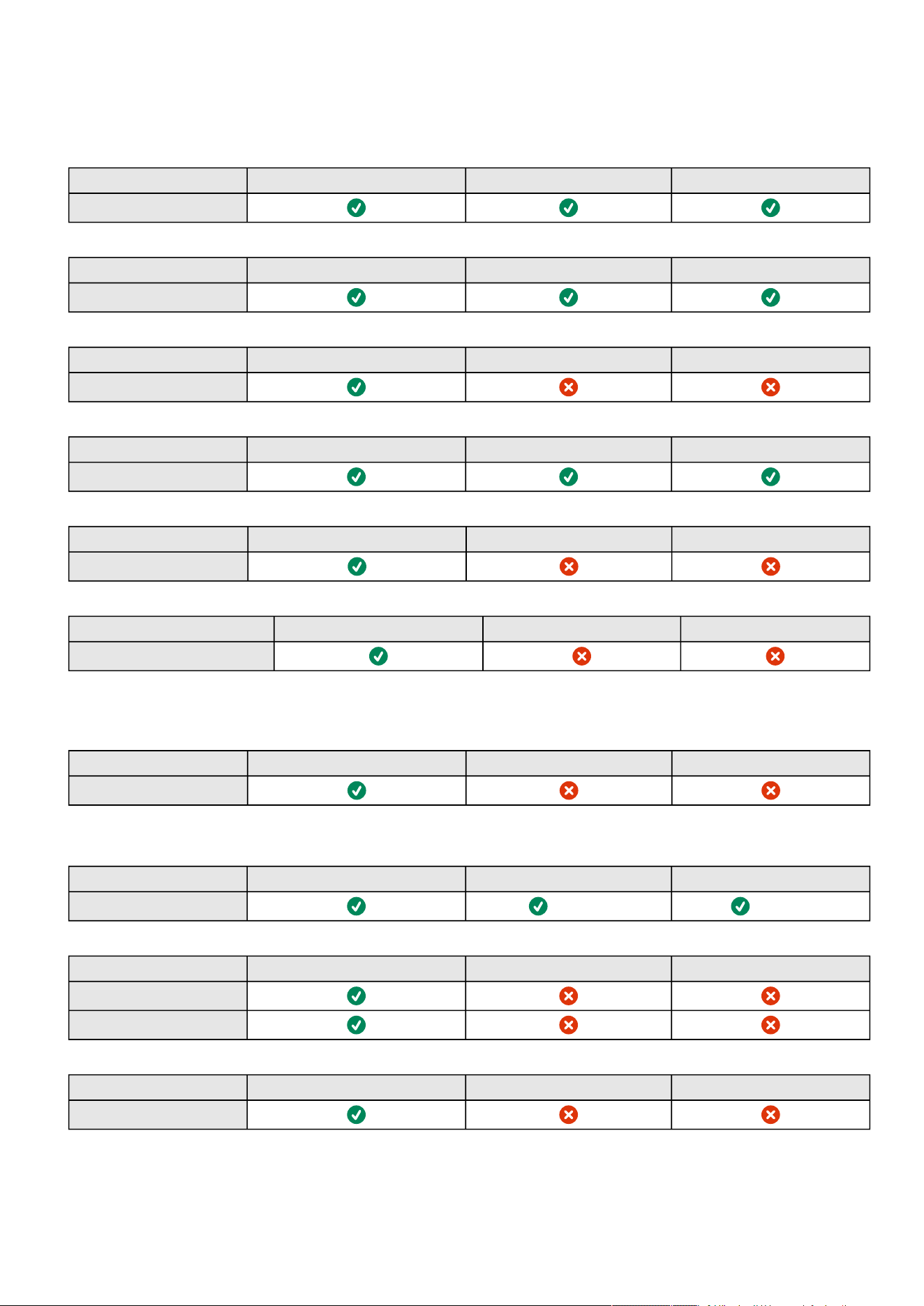
Access rights per profiles
Information – 209
7.4.11 CLI commands
Administrator Operator Viewer
get release info
Administrator Operator Viewer
history
Administrator Operator Viewer
ldap-test
Administrator Operator Viewer
logout
Administrator Operator Viewer
maintenance
Administrator Operator Viewer
modbus_message_display*
*for INDGW only
Administrator Operator Viewer
modbus_statistics*
*for INDGW only
Administrator Operator Viewer
netconf
(read-only) (read-only)
Administrator Operator Viewer
ping
ping6
Administrator Operator Viewer
reboot
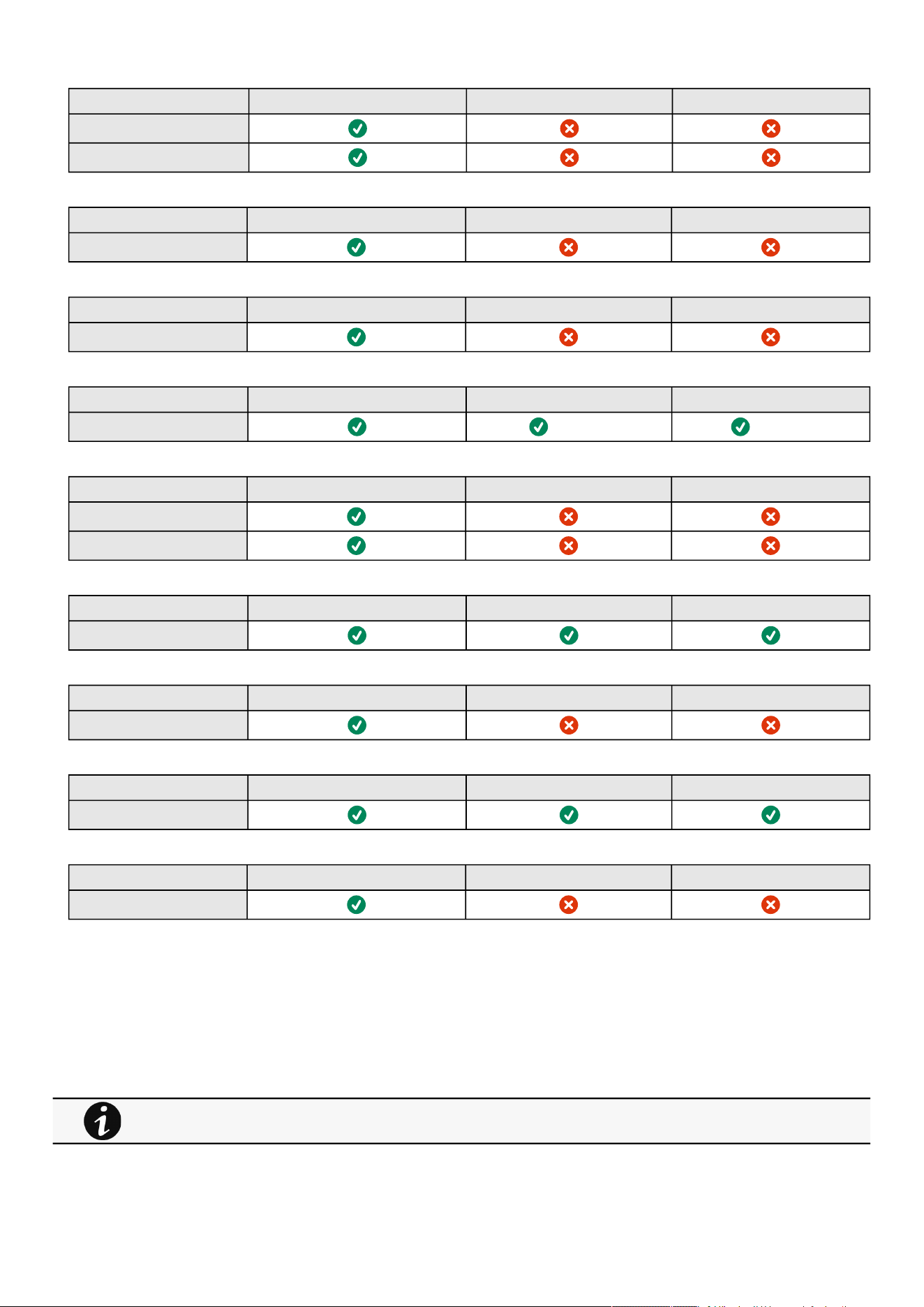
List of event codes
Information – 210
Administrator Operator Viewer
save_configuration
restore_configuration
Administrator Operator Viewer
sanitize
Administrator Operator Viewer
ssh-keygen
Administrator Operator Viewer
time
(read-only) (read-only)
Administrator Operator Viewer
traceroute
traceroute6
Administrator Operator Viewer
whoami
Administrator Operator Viewer
email-test
Administrator Operator Viewer
systeminfo_statistics
Administrator Operator Viewer
certificates
7.5 List of event codes
To get access to the Alarm log codes or the System log codes for email subscription, seesections below:
7.5.1 System log codes
To retrieve System logs, navigate to Contextual help>>>Maintenance>>>System logs section and press
theDownload System logsbutton.

List of event codes
Information – 211
7.5.1.1 Critical
Code Severity Log message File
0801000 Alert User account - admin password reset to default logAccount.csv
0E00400 Critical The [selfsign/PKI] signed certificate of the <service> server is not valid logSystem.csv
0A00700 Error Network module file system integrity corrupted <f/w: xx.yy.zzzz> logUpdate.csv
0000D00 Error Card reboot due to database error logSystem.csv
0700200 Error Failed to start execution of script "<script description>". Client not registered. (<script
uuid>)
logSystem.csv
0700400 Error Execution of script "<script description>" failed with return code: <script return code>.
(<script uuid>)
logSystem.csv
0700500 Error Execution of script "<script description>" timeout! (<script uuid>) logSystem.csv
0700700 Alert Failed to prepare isolated environment for script execution. Protection service startup is
aborted.
logSystem.csv
7.5.1.2 Warning
Code Severity Log message File
0A00200 Warning Network module upgrade failed <f/w: xx.yy.zzzz> logUpdate.csv
0A00A00 Warning Network module bootloader upgrade failed <f/w: xx.yy.zzzz> logUpdate.csv
0B00500 Warning RTC battery cell low logSystem.csv
0E00200 Warning New [self/PKI] signed certificate [generated/imported] for <service> server logSystem.csv
0E00300 Warning The [self/PKI] signed certificate of the <service> server will expires in <X> days logSystem.csv
0800700 Warning User account - password expired logAccount.csv
0800900 Warning User account- locked logAccount.csv
0C00100 Warning Unable to send email: Smtp server is unknown logSystem.csv
0C00200 Warning Unable to send email: Authentication method is not supported logSystem.csv
0C00300 Warning Unable to send email: Authentication error logSystem.csv
0C00500 Warning Unable to send email: Certificate Authority not recognized logSystem.csv
0C00600 Warning Unable to send email: Secure connection required logSystem.csv
0C00800 Warning Unable to send email: Unknown error logSystem.csv
0C00B00 Warning Unable to send email: Recipient not specified logSystem.csv
0F01300 Warning Card reboot due to Device FW upgrade logSystem.csv
1000F00 Warning <
feature
> settings partial restoration logSystem.csv
1001000 Warning <
feature
> settings restoration error logSystem.csv
1000C00 Warning Settings partial restoration logSystem.csv
1000D00 Warning Settings restoration error logSystem.csv
Below codes are the one to be used to add "Exceptions on events notification" on email sending configurations.
Some zeros maybe added in front of the code when displayed in emails or logs.

List of event codes
Information – 212
7.5.1.3 Info
Code Severity Log message File
0300D00 Notice User action - sanitization launched logSystem.csv
0A00500 Notice Network module sanitized logUpdate.csv
0A00900 Notice Network module bootloader upgrade success <f/w: xx.yy.zzzz> logUpdate.csv
0A00B00 Notice Network module bootloader upgrade started <f/w: xx.yy.zzzz> logUpdate.csv
0A00C00 Notice Periodic system integrity check started logUpdate.csv
0B00100 Notice Time manually changed logSystem.csv
0B00700 Notice NTP sever not available <NTP server address> logSystem.csv
0900100 Notice Session - opened logSession.csv
0900200 Notice Session - closed logSession.csv
0900300 Notice Session - invalid token logSession.csv
0900400 Notice Session - authentication failed logSession.csv
0300F00 Notice User action - network module admin password reset switch activated logSystem.csv
0E00500 Notice [Certificate authority/ Client certificate] <id> is added for <service> logSystem.csv
0E00600 Notice [Certificate authority/ Client certificate] <id> is revoked for <service> logSystem.csv
0700100 Info Start execution of script "<script description>". (<script uuid>) logSystem.csv
0700300 Info Execution of script "<script description>" succeeded. (<script uuid>) logSystem.csv
0700600 Info/Notice/
Error/Debug
<Script execution log message> logSystem.csv
0800100 Notice User account - created <user account id> logAccount.csv
0800200 Notice User account - deleted <user account id> logAccount.csv
0800400 Notice User account - name changed <user account id> logAccount.csv
0800600 Notice User account - password changed logAccount.csv
0800800 Notice User account- password reset <user account id> logAccount.csv
0800A00 Notice User account- unlocked logAccount.csv
0800B00 Notice User account - activated <user account id> logAccount.csv
0800C00 Notice User account - deactivated <user account id> logAccount.csv
0801401 Info User account - Invalid credentials reserved username logAccount.csv
0900D00 Notice <user> connected into interactive CLI with session id XXXXXX logSession.csv
0900E00 Notice <user> disconnected from interactive CLI with session id XXXXXX logSession.csv
0900F00 Notice <user> doesn't have access to CLI - CLI session id XXXXXX logSession.csv
0901000 Notice <user> connected and executes remote command <command> into the CLI - CLI
session id XXXXXX
logSession.csv
0901100 Notice <user> finished executing remote command <command> into the CLI - CLI session
id XXXXXX
logSession.csv
0901200 Notice <user> connection rejected - CLI session id XXXXXX logSession.csv
0901300 Notice <user> disconnected from interactive CLI with session id XXXXXX due to session
timeout
logSession.csv
0901400 Notice <user> disconnected from interactive CLI with session id XXXXXX due to concurrent
connection with session id XXXXXX
logSession.csv
0100C00 Notice Syslog is started logSystem.csv

List of event codes
Information – 213
0100B00 Notice Syslog is stopping logSystem.csv
0100D00 Notice Network module is booting logSystem.csv
0100E00 Notice Network module is operating logSystem.csv
0100F00 Notice Network module is starting shutdown sequence logSystem.csv
0101000 Notice Network module is ending shutdown sequence logSystem.csv
0101400 Notice Network module shutdown requested logSystem.csv
0101500 Notice Network module reboot requested logSystem.csv
0100200 Notice <nb alarms> alarms exported and flushed logSystem.csv
0A00100 Info Network module upgrade success <f/w: xx.yy.zzzz> logUpdate.csv
0A00300 Info Network module upgrade started logUpdate.csv
0A00600 Info Network module file system integrity OK <f/w: xx.yy.zzzz> logUpdate.csv
0B00300 Info Time with NTP synchronized logSystem.csv
0B00600 Info Time settings changed logSystem.csv
0B01100 Info Time reset to last known date: "date" logSystem.csv
0C00F00 Info Test email
1000100 Info Settings saving requested logSystem.csv
1000200 Info <
feature
> settings saved logSystem.csv
1000A00 Info Settings restoration requested logSystem.csv
1000E00 Info <
feature
> settings restoration success logSystem.csv
1000B00 Info Settings restoration success logSystem.csv
0301500 Notice Sanitization switch changed logSystem.csv
0A01600 Notice Major version downgrade logUpdate.csv
0D00800 Notice DHCP client script called with <script parameters> logSystem.csv
0D00900 Notice IPv4 configuration changed to <ipsv4_address> logSystem.csv
0D01000 Notice IPv6 configuration changed to <ipsv6_address> logSystem.csv
Event with code0700600 is used within shutdown script. The severity may vary according to the event context.

List of event codes
Information – 214
7.5.2 UPS(HID) alarm log codes
7.5.2.1 Critical
Code Severity Active message Non-active message Advice
002 Critical Internal failure End of internal failure Service required
004 Critical Temperature alarm Temperature OK Check air conditioner
100 Critical Rectifier fuse fault Rectifier fuse OK Service required
105 Critical Input AC module failure Input AC module OK Service required
207 Critical Bypass AC module failure Bypass AC module OK -
208 Critical Bypass overload No bypass overload -
305 Critical Rectifier failure Rectifier OK Service required
306 Critical Rectifier overload Rectifier OK Reduce output load
308 Critical Rectifier short circuit Rectifier OK Reduce output load
400 Critical DCDC converter failure DCDC converter OK Service required
500 Critical Battery charger fault Battery charger OK Service required
607 Critical Battery test failed Battery test OK Check battery
60D Critical No battery Battery present Check battery
61B Critical Battery BMS fault Battery BMS OK Check battery
629 Critical Battery voltage low critical Batteryvoltage OK Check battery
62B Critical Battery voltage high critical Batteryvoltage OK Check battery
62D Critical Battery charge current low critical Batterycharge current OK Check battery
62F Critical Batterycharge current high critical Batterycharge current OK Check battery
631 Critical Battery discharge current low
critical
Batterydischarge current OK Check battery
633 Critical Batterydischarge current high
critical
Batterydischarge current OK Check battery
635 Critical Battery temperature low critical Batterytemperature OK Check battery
637 Critical Batterytemperature high critical Battery temperature OK Check battery
63E Critical Battery fault Battery OK Check battery
704 Critical Inverter internal failure UPS OK Service required
705 Critical Inverter overload No power overload Reduce output load
706 Critical Temperature alarm Temperature OK Check air conditioner
70B Critical Inverter short circuit End of inverter short circuit Service required
805 Critical Output short circuit Output OK Reduce output load
This table applies to all UPS except to the 9130 UPS.
To retrieve Alarm logs, navigate to Contextual help>>>Alarms section and press the Download alarms button.
Below codes are the one to be used to add "Exceptions on events notification" on email sending configurations.
Some zeros maybe added in front of the code when displayed in emails or logs.

List of event codes
Information – 215
811 Critical Parallel negative power Parallel power OK Reduce output load
815 Critical Calibration fault Calibration OK Service required
81E Critical Load unprotected Load protected -
7.5.2.2 Warning
Code Severity Active message Non-active message Advice
001 Warning On battery No more on battery -
007 Warning Fan fault Fan OK Service required
00B Warning Parallel UPS redundancy lost Parallel UPS redundancy OK Reduce output load
00E Warning Parallel UPS communication lost Parallel UPS communication OK Service required
00F Warning Parallel UPS not compatible Parallel UPS compatibility OK Service required
010 Warning UPS power supply fault UPS power supply OK Service required
011 Warning Parallel UPS protection lost Parallel UPS protection OK Reduce output load
012 Warning Parallel UPS measure inconsistent Parallel UPS measure OK Service required
103 Warning Utility breaker open Utility breaker closed -
104 Warning Input AC frequency out of range Input AC frequency in range -
106 Warning Input AC not present Input AC present -
107 Warning Input bad wiring Input wiring OK Check input wiring
108 Warning Input AC voltage out of range (-) Input AC voltage in range -
109 Warning Input AC voltage out of range (+) Input AC voltage in range -
110 Warning Building alarm (through dry
contact)
Building alarm OK -
11F Warning Building alarm (through Network
module)
Building alarm OK -
10A Warning Input AC unbalanced End of input AC unbalanced -
200 Warning Bypass phase out range Bypass phase in range -
201 Warning Bypass not available Bypass available Service required
202 Warning Bypass thermal overload Bypass thermal OK Reduce output load
203 Warning Bypass temperature alarm Bypass temperature OK Check air conditioner
204 Warning Bypass breaker open Bypass breaker closed -
205 Warning Bypass mode No more on bypass -
206 Warning Bypass frequency out of range Bypass frequency in range -
209 Warning Bypass voltage out of range Bypass voltage in range -
20A Warning Bypass AC over voltage End of bypass AC over voltage -
20B Warning Bypass AC under voltage End of bypass AC under voltage -
20C Warning Bypass bad wiring Bypass wiring OK Check bypass wiring
300 Warning DC bus + too high DC bus + voltage OK Service required
301 Warning DC bus - too high DC bus - voltage OK Service required
302 Warning DC bus + too low DC bus + voltage OK Service required
303 Warning DC bus - too low DC bus - voltage OK Service required
304 Warning DC bus unbalanced DC bus OK Service required
501 Warning Charger temperature alarm Charger temperature OK Service required

List of event codes
Information – 216
502 Warning Max charger voltage Charger voltage OK Service required
503 Warning Min charger voltage Charger voltage OK Service required
600 Warning Battery fuse fault Battery fuse OK Service required
602 Warning Battery fuse fault Battery fuse OK Service required
604 Warning Battery low state of charge Battery state of charge OK -
605 Warning Battery temperature alarm Battery temperature OK Service required
606 Warning Battery breaker open Battery breaker closed Service required
610 Warning Battery low voltage Battery voltage OK Check battery
613 Warning Battery voltage too high Battery voltage OK Check battery
616 Warning Battery voltage unbalanced Battery voltage OK Check battery
618 Warning Battery voltage too low Battery voltage OK Check battery
61C Warning Communication with battery lost Communication with battery
recovered
Check battery
61E Warning At least one breaker in battery is
open
All battery breakers are closed Check battery
61F Warning Battery State Of Charge below
limit
Battery State Of Charge OK -
620 Warning Battery State Of Health below limit Battery State Of Health OK Check battery
628 Warning Battery voltage low warning Battery voltage OK Check battery
62A Warning Battery voltage high warning Battery voltage OK Check battery
62C Warning Batterycharge current low
warning
Batterycharge current OK Check battery
62E Warning Batterycharge current high
warning
Batterycharge current OK Check battery
630 Warning Battery discharge current low
warning
Battery discharge current OK Check battery
632 Warning Battery discharge current high
warning
Battery discharge current OK Check battery
634 Warning Battery temperature low warning Battery temperature OK Check battery
636 Warning Batterytemperature high warning Batterytemperature OK Check battery
638 Warning Battery BMS failure Battery BMS OK Check battery
639 Warning Battery temperature unbalanced Batterytemperature OK Check battery
63D Warning Battery warning Battery OK Check battery
700 Warning Inverter limitation No current limitation Reduce output load
701 Warning Inverter fuse fault Inverter fuse OK Service required
70A Warning Inverter thermal overload No power overload Reduce output load
70C Warning Inverter voltage too low Inverter voltage OK Service required
70D Warning Inverter voltage too high Inverter voltage OK Service required
801 Warning Load not powered Load powered -
803 Warning Output breaker open Output breaker closed -
806 Warning Emergency power OFF No emergency OFF -
808 Warning Power overload No power overload Reduce output load
80D Warning Internal configuration failure Internal configuration OK Service required
80E Warning Overload pre-alarm No overload pre-alarm Reduce output load
810 Warning Overload alarm No overload Reduce output load
814 Warning Firmware watchdog reset Firmware watchdog OK Service required

List of event codes
Information – 217
816 Warning Compatibility failure Compatibility OK Service required
817 Warning Output over current No output over current Reduce output load
818 Warning Output frequency out of range Output frequency in range Service required
819 Warning Output voltage too high Output voltage OK Service required
81A Warning Output voltage too low Output voltage OK Service required
81B Warning UPS Shutoff requested End of UPS shutoff requested Service required
81D Warning Load not powered Load protected -
81F Warning Output phase 1 overload Output phase 1 no overload -
820 Warning Output phase 2 overload Output phase 2 no overload -
821 Warning Output phase 3 overload Output phase 3 no overload -
900 Warning Maintenance bypass Not on maintenance bypass -
901 Warning Maintenance bypass breaker
closed
Maintenance bypass breaker open -
B01 Warning Batteries are aging. Consider
replacement
Batteries aging condition cleared -
7.5.2.3 Info
Code Severity Active message Non-active message Advice
005 Info Communication lost (with UPS) Communication recovered (with
UPS)
Service required
013 Info Upgrading: limited communication End of upgrade mode -
101 Info On AVR (Boost) End of AVR (Boost) -
102 Info On AVR (Buck) End of AVR (Buck) -
603 Info Battery discharging End of UPS battery discharge -
63C Info Battery information Battery OK -
A00 Info Group 1 is OFF Group 1 is ON -
A01 Info Group 2 is OFF Group 2 is ON -
A0F Info Group is OFF Group is ON -
7.5.2.4 Good
Code Severity Active message Non-active message
009 Good On high efficiency / On ESS mode High efficiency disabled / ESS disabled
60E Good UPS external battery set as “No battery” UPS external battery set as present
826 Good Load powered with no continuity Load protected
Alarms with a severity set as Good are not taken into account into the counter of active alarms.

List of event codes
Information – 218
7.5.3 UPS(XCP and COPI) alarm log codes
7.5.3.1 Critical
Code Severity Active message Non-active message Advice
2002 Critical Inverter AC frequency out of range Inverter AC frequency in range -
2012 Critical Emergency power OFF No emergency OFF -
2020 Critical Bypass temperature alarm Bypass temperature OK -
2022 Critical Charger power supply tripped Charger power supply no longer
tripped
-
2024 Critical Inverter Temperature too high Inverter Temperature OK -
2026 Critical Rectifier current too high Rectifier OK -
2030 Critical Rectifier failure Rectifier current OK -
2031 Critical Inverter internal failure UPS OK -
2032 Critical Battery breaker failure Battery breaker OK -
2033 Critical Automatic bypass breaker failure Automatic bypass breaker OK -
2034 Critical Battery charger fault Battery charger OK -
2036 Critical Bypass AC static switch failure Bypass AC static switch OK -
2246 Critical Neutral current limitation Neutral current OK -
2048 Critical Inverter Start failure Inverter Start OK -
2051 Critical Battery ground fault Battery ground OK -
2053 Critical Non volatile memory failure Non volatile memory OK -
2055 Critical UPS shutdown imminent UPS shutdown no longer imminent -
2056 Critical Battery low state of charge Battery state of charge OK -
2058 Critical Output short circuit Output OK -
2064 Critical Rectifier self test failed Rectifier self test OK -
2068 Critical Battery voltage too high Battery voltage OK -
2070 Critical UPS power supply fault UPS power supply OK -
2073 Critical Temperature too high Temperature OK -
2075 Critical Rectifier overload Rectifier OK -
2076 Critical Rectifier Offline due to
overtemperature
Rectifier no longer tripped -
2077 Critical Input AC module failure Input AC module OK -
2079 Critical Inverter self test failed Inverter self test OK -
2089 Critical Output voltage DC offset too high Output voltage DC offset OK -
Use this table for 9130, 9x55, 9395P, BladeUPS.
To retrieve Alarm logs, navigate to Contextual help>>>Alarms section and press the Download alarms button.
Below codes are the one to be used to add "Exceptions on events notification" on email sending configurations.
Some zeros maybe added in front of the code when displayed in emails or logs.

List of event codes
Information – 219
2111 Critical Inverter Offline due to
overtemperature
Inverter no longer tripped -
2112 Critical DC/DC converter failure DC/DC converter OK -
2116 Critical Charger voltage too low Charger voltage OK -
2126 Critical Battery totally discharged Battery no longer totally discharged -
2133 Critical Loss of Sync bus Sync bus recovered -
2149 Critical Battery needs service Battery OK -
2157 Critical Output breaker failure Output breaker OK -
2165 Critical Output phase 1 extreme overload Output phase 1 no extreme
overload
-
2166 Critical Output phase 2 extreme overload Output phase 2 no extreme
overload
-
2167 Critical Output phase 3 extreme overload Output phase 3 no extreme
overload
-
2177 Critical Inverter Temperature sensor failed Inverter Temperature sensor OK -
2186 Critical Emergency transfer to bypass Back from bypass -
2188 Critical Bypass AC module failure Bypass AC module OK -
2191 Critical Battery fault Battery OK Check battery
2192 Critical Fuse fault Fuse OK -
2193 Critical Fan fault Fan OK -
2195 Critical Backfeed bypass contactor failure Backfeed bypass contactor OK -
2199 Critical Battery not present Battery present Check battery
2200 Critical Temperature out of range Temperature in range -
2201 Critical Transformer Temperature too high Transformer Temperature OK -
2217 Critical Utility input breaker failure Utility input breaker OK -
2220 Critical UPS module taken out of parallel
system
UPS module back on parallel
system
-
2223 Critical Rectifier over temperature Rectifier temperature OK -
2229 Critical At least one critical alarm active No critical alarm active -
2238 Critical Inverter phases out of sequence Inverter phases wired OK -
2240 Critical External CAN network fault External CAN network OK -
2242 Critical Inverter breaker failure Inverter breaker OK -
2249 Critical Rectifier over temperature tripped Rectifier temperature OK -
2259 Critical Rectifier short circuit Rectifier OK -
2260 Critical Rectifier short circuit Rectifier OK -
2261 Critical Rectifier short circuit Rectifier OK -
2323 Critical Inverter overload No power overload -
2324 Critical Inverter short circuit End of inverter short circuit -
2325 Critical Bypass overload No bypass overload -
2328 Critical Bypass thermal overload Bypass thermal OK -
2364 Critical Internal failure End of internal failure -
2365 Critical Ground fault Ground OK -
2380 Critical Output phase 1 excessive overload Output phase 1 no excessive
overload
-

List of event codes
Information – 220
2381 Critical Output phase 2 excessive overload Output phase 2 no excessive
overload
-
2382 Critical Output phase 3 excessive overload Output phase 3 no excessive
overload
-
2386 Critical Major alarm condition that makes UPS
need service
No major alarm condition -
2387 Critical Battery voltage low Battery voltage no longer low -
2392 Critical Automatic bypass static switch current
too high
Automatic bypass static switch
current OK
-
2402 Critical Parallel UPS not compatible Parallel UPS compatibility OK -
7.5.3.2 Warning
Code Severity Active message Non-active message Advice
2000 Warning Inverter voltage too high Inverter voltage OK -
2001 Warning Inverter voltage too low Inverter voltage OK -
2003 Warning Bypass AC over voltage End of bypass AC over voltage -
2004 Warning Bypass AC under voltage No Bypass AC under voltage -
2005 Warning Bypass frequency out of range Bypass frequency in range -
2006 Warning Input AC voltage out of range (+) Input AC voltage in range -
2007 Warning Input AC voltage out of range (-) Input AC voltage in range -
2008 Warning Input AC frequency out of range Input AC frequency in range -
2009 Warning Output voltage too high Output voltage OK -
2010 Warning Output voltage too low Output voltage OK -
2011 Warning Output frequency out of range Output frequency in range -
2012 Warning Emergency power OFF No emergency OFF -
2021 Warning Charger over temperature Charger temperature OK -
2023 Warning Charger over voltage or current Charger voltage or current OK -
2025 Warning Power overload No power overload -
2027 Warning Inverter output current too high Inverter output current OK -
2028 Warning DC bus voltage too high DC bus voltage OK -
2029 Warning DC bus voltage too low DC bus voltage OK -
2047 Warning Battery discharge current too high Battery discharge current OK -
2056 Warning Battery voltage or energy too low Battery voltage or energy OK -
2057 Warning On battery No more on battery -
2063 Warning Internal communication failure Internal communication OK -
2067 Warning Input AC not present Input AC present -
2075 Warning Rectifier input or output over
current
Rectifier current OK -
2102 Warning Inverter L1 current too high Inverter L1 current OK -
2103 Warning Inverter L2 current too high Inverter L2 current OK -
2104 Warning Inverter L3 current too high Inverter L3 current OK -
2105 Warning Bypass available Bypass not available -
2106 Warning Utility input breaker closed Utility input breaker open -

List of event codes
Information – 221
2107 Warning Battery breaker open Battery breaker closed -
2108 Warning Inverter breaker open Inverter breaker closed -
2109 Warning Automatic bypass breaker open Automatic bypass breaker closed -
2112 Warning DC/DC converter failure DC/DC converter OK -
2118 Warning Input phases out of sequence Input phases wired OK -
2119 Warning Bypass phases out of sequence Bypass phases wired OK -
2132 Warning Parallel UPS redundancy lost Parallel UPS redundancy OK -
2137 Warning Output breaker open Output breaker closed -
2142 Warning Bypass source power not
sufficient
Bypass source power OK -
2143 Warning On maintenance bypass No more on maintenance bypass -
2147 Warning Firmware watchdog reset Firmware watchdog OK -
2159 Warning Output phase 1 overload pre-alarm Output phase 1 no overload pre-alarm -
2160 Warning Output phase 2 overload pre-alarm Output phase 2 no overload pre-alarm -
2161 Warning Output phase 3 overload pre-alarm Output phase 3 no overload pre-alarm -
2162 Warning Output phase 1 overload Output phase 1 no overload -
2163 Warning Output phase 2 overload Output phase 2 no overload -
2164 Warning Output phase 3 overload Output phase 3 no overload -
2168 Warning Battery discharging Battery no longer discharging -
2169 Warning On bypass No longer on bypass -
2170 Warning Load not powered Load powered -
2176 Warning Compatibility failure Compatibility OK -
2189 Warning Load not powered Load powered -
2194 Warning Input bad wiring Input wiring OK -
2206 Warning UPS Shutdown requested End of UPS shutdown requested -
2208 Warning Charger unable to charge battery Charger can charge battery -
2224 Warning Internal configuration failure Internal configuration OK -
2231 Warning DC bus unbalanced DC bus OK -
2253 Warning Moment Static Switch open Moment Static Switch closed -
2259 Warning Rectifier L1 current too high Rectifier L1 current OK -
2260 Warning Rectifier L2 current too high Rectifier L2 current OK -
2261 Warning Rectifier L3 current too high Rectifier L3 current OK -
2306 Warning Bypass breaker open Bypass breaker closed -
2309 Warning Output phases are rotated Output phases wired OK -
2322 Warning Battery temperature too high Battery temperature OK -
2326 Warning Bypass phase out range Bypass phase in range -
2327 Warning Bypass voltage out of range Bypass voltage in range -
2342 Warning Overload pre-alarm No overload pre-alarm -
2364 Warning Internal failure End of internal failure -
2366 Warning Bypass bad wiring Bypass wiring OK -
2369 Warning Battery low state of charge Battery state of charge OK -
2384 Warning Major alarm condition that makes
UPS fail
No major alarm condition -
2395 Warning Bypass frequency out of sync Bypass frequency no longer out of sync -

List of event codes
Information – 222
2396 Warning Input frequency out of sync Input frequency no longer out of sync -
2397 Warning Output frequency out of sync Output frequency no longer out of sync -
7.5.3.3 Info
Code Severity Active message Non-active message Advice
2014 Info Building alarm 6 No building alarm 6 -
2015 Info Building alarm 5 No building alarm 5 -
2016 Info Building alarm 4 No building alarm 4 -
2017 Info Building alarm 3 No building alarm 3 -
2018 Info Building alarm 2 No building alarm 2 -
2019 Info Building alarm 1 No building alarm 1 -
2038 Info Bypass AC sensor not
calibrated
Bypass AC sensor OK -
2039 Info Input AC sensor not calibrated Input AC sensor calibrated -
2040 Info Output AC sensor not
calibrated
Output AC sensor calibrated -
2041 Info Inverter sensor not calibrated Inverter sensor calibrated -
2042 Info DC bus sensor not calibrated DC bus sensor calibrated -
2043 Info Output AC current sensor not
calibrated
Output AC current sensor calibrated -
2044 Info Input AC current sensor not
calibrated
Input AC current sensor calibrated -
2045 Info Battery current sensor not
calibrated
Battery current sensor calibrated -
2059 Info Utility AC not present Utility AC present -
2063 Info Internal communication failure Internal communication OK -
2121 Info Parallel UPS internal failure Parallel UPS OK -
2130 Info Charger current too high Charger current OK -
2135 Info Charger not synchronized with
input phase
Charger synchronized with input phase -
2168 Info Battery discharging UPS battery no longer discharging -
2185 Info Automatic bypass breaker
should be closed
Automatic bypass breaker closed -
2196 Info On AVR (Buck) End of AVR (Buck) -
2197 Info On AVR (Boost) End of AVR (Boost) -
2202 Info Ambient temperature is too
Low
Ambient temperature is OK -
2204 Info Door or cover of the UPS open Door or cover of the UPS closed -
2211 Info Modem connection fault Modem connection OK -
2227 Info On high efficiency or ESS No longer on High efficiency or ESS -
2228 Info At least one informational alarm
active
No informational alarms active -
2247 Info Battery breaker should be
closed
Battery breaker closed -
2370 Info Building alarm 7 Building alarm 7 OK -

List of event codes
Information – 223
2371 Info Building alarm 8 Building alarm 8 OK -
2372 Info Building alarm 9 Building alarm 9 OK -
2383 Info Condition to call user true No condition to call user -
2385 Info Service scheduled Service no longer scheduled -

List of event codes
Information – 224
7.5.4 ATS alarm log codes
7.5.4.1 Critical
Code Severity Active message Non-active message Advice
F03 Critical Internal failure End of internal failure -
F08 Critical Internal failure End of internal failure -
F0B Critical Internal failure End of internal failure -
F0D Critical In short circuit Not in short circuit -
F10 Critical Load not powered Load powered with no continuity -
F11 Critical Internal failure End of internal failure -
F13 Critical Temperature out of range Temperature in range -
F1B Critical Off On preferred source -
7.5.4.2 Warning
Code Severity Active message Non-active message Advice
F00 Warning Unsynchronized sources Synchronized sources -
F01 Warning Frequency out of range Frequency in range -
F02 Warning Out of range In range -
F04 Warning Voltage in derated range Voltage in normal range -
F06 Warning Frequency out of range Frequency in range -
F07 Warning Not in range In range -
F09 Warning Voltage in derated range Voltage in normal range -
F0C Warning In overload Not in overload -
F0F Warning Internal configuration failure Internal configuration OK -
F12 Warning Overload Fault No overload fault -
F15 Warning Input waveform is not OK Input waveform is OK -
F16 Warning Voltage out of range Voltage in range -
F17 Warning Input waveform is not OK Input waveform is OK -
F18 Warning Voltage out of range Voltage in range -
F1A Warning On alternate source - -
To retrieve Alarm logs, navigate to Contextual help>>>Alarms section and press the Download alarms button.
Below codes are the one to be used to add "Exceptions on events notification" on email sending configurations.
Some zeros maybe added in front of the code when displayed in emails or logs.

List of event codes
Information – 225
7.5.4.3 Good
Code Severity Active message Non-active message Advice
F05 Good Source 1 used to power the load Source 1 not used to power the load -
F0A Good Source 2 used to power the load Source 2 not used to power the load -
F19 Good On preferred source - -
Alarms with a severity set as Good are not taken into account into the counter of active alarms.

List of event codes
Information – 226
7.5.5 EMP alarm log codes
7.5.5.1 Critical
Code Severity Active message Non-active message Advice
1201 Critical Temperature is critically low Temperature is back to low -
1204 Critical Temperature is critically high Temperature is back to high -
1211 Critical Humidity is critically low Humidity is back to low -
1214 Critical Humidity is critically high Humidity is back to high -
7.5.5.2 Warning
Code Severity Active message Non-active message Advice
1200 Warning Communication lost Communication recovered -
1202 Warning Temperature is low Temperature is back to normal -
1203 Warning Temperature is high Temperature is back to normal -
1212 Warning Humidity is low Humidity is back to normal -
1213 Warning Humidity is high Humidity is back to normal -
7.5.5.3 With settable severity
Code Severity Active message Non-active message Advice
1221 Settable Contact is active Contact is back to normal -
To retrieve Alarm logs, navigate to Contextual help>>>Alarms section and press the Download alarms button.
Below codes are the one to be used to add "Exceptions on events notification" on email sending configurations.
Some zeros maybe added in front of the code when displayed in emails or logs.

List of event codes
Information – 227
7.5.6 Network module alarm log codes
7.5.6.1 Warning
7.5.6.1.1 Protection
Code Severity Active message Non-active message Advice
1032 Warning Protection: immediate shutdown in progress Protection: immediate shutdown completed -
1053 Warning Protection: communication lost with agent Protection: communication recovered with agent -
7.5.6.1.2 Alarms
Code Severity Active message Non-active message Advice
1303 Warning Alarms: the number of alarms is too
high and above 6 000
Alarms: the number of alarms is
back to normal
2 000 alarms have been
erased and saved in a
backup file.
7.5.6.2 Info
7.5.6.2.1 Protection
Code Severity Active message Non-active message Advice
1016 Info Protection: sequential shutdown scheduled Protection: sequential shutdown canceled -
1017 Info Protection: sequential shutdown in progress Protection: sequential shutdown completed -
1054 Info Protection: agent is in unknown state Protection: agent is in service -
1055 Info Protection: agent is starting Protection: agent is in service -
1056 Info Protection: agent is stopping Protection: agent is in service -
1057 Info Protection: agent is stopped Protection: agent is in service -
1100 Info Schedule: shutdown date reached Schedule: shutdown initiated -
7.5.6.2.2 Communication
Code Severity Active message Non-active message Advice
1300 Info Communication: No device connected Communication: Communication with the device is back -
To retrieve Alarm logs, navigate to Contextual help>>>Alarms section and press the Download alarms button.
Below codes are the one to be used to add "Exceptions on events notification" on email sending configurations.
Some zeros maybe added in front of the code when displayed in emails or logs.

SNMP traps
Information – 228
1301 Info Communication: Device not supported Communication: Communication with the device is back -
7.5.6.2.3 Alarms
Code Severity Active message Non-active message Advice
1302 Info Alarms: the number of alarms is
high and above 5 000
Alarms: the number of alarms is
back to normal
It is recommended to
Export and Clear the alarm
log.
7.6 SNMP traps
7.6.1 UPS Mib
7.6.1.1 IETF Mib-2 Ups traps
This information is for reference only.
Trap oid :
.1.3.6.1.2.1.33.2.0.x
Description :
.1.3.6.1.2.1.33.2.0.1 Sent whenever the UPS transfers on battery,
then sent every minutes until the UPS Comes back to AC Input.
.1.3.6.1.2.1.33.2.0.3 Sent whenever an alarm appears.
The matching alarm oid is added as bound variables in the table below.
.1.3.6.1.2.1.33.2.0.4 Sent whenever an alarm disappears.
The matching alarm oid is added as bound variables in the table below.
Alarm oid at :
.1.3.6.1.2.1.33.1.6.3.x
Description when trap 3 Description when trap 4
.1.3.6.1.2.1.33.1.6.3.1 Battery test failed Battery test OK
.1.3.6.1.2.1.33.1.6.3.2 Battery discharging End of UPS battery discharge
.1.3.6.1.2.1.33.1.6.3.3 Low battery Battery OK
.1.3.6.1.2.1.33.1.6.3.5 Temperature alarm Temperature OK
.1.3.6.1.2.1.33.1.6.3.6 Input AC not present Input AC present
.1.3.6.1.2.1.33.1.6.3.8 Power overload No power overload
.1.3.6.1.2.1.33.1.6.3.9 Bypass mode No more on bypass
.1.3.6.1.2.1.33.1.6.3.10 Bypass not available Bypass available
.1.3.6.1.2.1.33.1.6.3.13 Battery charger fault Battery charger OK
.1.3.6.1.2.1.33.1.6.3.14 Not powered Powered (Protected or Not protected)
.1.3.6.1.2.1.33.1.6.3.16 Fan fault Fan OK
.1.3.6.1.2.1.33.1.6.3.17 Battery fuse fault
Rectifier fuse fault
Inverter fuse fault
Battery fuse OK
Rectifier fuse OK
Inverter fuse OK

SNMP traps
Information – 229
Alarm oid at :
.1.3.6.1.2.1.33.1.6.3.x
Description when trap 3 Description when trap 4
.1.3.6.1.2.1.33.1.6.3.18 Internal failure End of internal failure
.1.3.6.1.2.1.33.1.6.3.20 Communication lost Communication recovered
.1.3.6.1.2.1.33.1.6.3.23 Shutdown imminent Shutdown canceled
7.6.1.2 Xups Mib traps
This information is for reference only.
Trap oid :
.1.3.6.1.4.1.534.1.11.4.1.0.x
Trap message at oid :
.1.3.6.1.4.1.534.1.11.3.0
.1.3.6.1.4.1.534.1.11.4.1.0.3 Battery discharging
.1.3.6.1.4.1.534.1.11.4.1.0.4 Battery low
.1.3.6.1.4.1.534.1.11.4.1.0.5 No more on battery
.1.3.6.1.4.1.534.1.11.4.1.0.6 Battery OK
.1.3.6.1.4.1.534.1.11.4.1.0.7 Power overload
.1.3.6.1.4.1.534.1.11.4.1.0.8 Internal failure
.1.3.6.1.4.1.534.1.11.4.1.0.10 Inverter internal failure
.1.3.6.1.4.1.534.1.11.4.1.0.11 Bypass mode
.1.3.6.1.4.1.534.1.11.4.1.0.12 Bypass not available
.1.3.6.1.4.1.534.1.11.4.1.0.13 Load not powered
.1.3.6.1.4.1.534.1.11.4.1.0.14 On battery
.1.3.6.1.4.1.534.1.11.4.1.0.15 Building alarm through input dry contact
.1.3.6.1.4.1.534.1.11.4.1.0.16 Shutdown imminent
.1.3.6.1.4.1.534.1.11.4.1.0.17 No more on bypass
.1.3.6.1.4.1.534.1.11.4.1.0.20 Breaker open
.1.3.6.1.4.1.534.1.11.4.1.0.23 Battery test failed
.1.3.6.1.4.1.534.1.11.4.1.0.26 Communication lost
.1.3.6.1.4.1.534.1.11.4.1.0.30 Sensor contact is active
.1.3.6.1.4.1.534.1.11.4.1.0.31 Sensor contact back to normal
.1.3.6.1.4.1.534.1.11.4.1.0.32 Parallel UPS redundancy lost
.1.3.6.1.4.1.534.1.11.4.1.0.33 Temperature alarm
.1.3.6.1.4.1.534.1.11.4.1.0.34 Battery charger fault
.1.3.6.1.4.1.534.1.11.4.1.0.35 Fan fault
.1.3.6.1.4.1.534.1.11.4.1.0.36 Fuse fault
.1.3.6.1.4.1.534.1.11.4.1.0.42 Sensor temperature is below/above critical threshold
.1.3.6.1.4.1.534.1.11.4.1.0.43 Sensor humidity is below/above critical threshold
.1.3.6.1.4.1.534.1.11.4.1.0.48 Maintenance bypass
7.6.2 ATS Mib
This information is for reference only.

SNMP traps
Information – 230
Trap oid :
.1.3.6.1.4.1.534.10.2.10.x
Trap description
.1.3.6.1.4.1.534.10.2.10.1 Communication lost
.1.3.6.1.4.1.534.10.2.10.2 Communication recovered
.1.3.6.1.4.1.534.10.2.10.3 Output powered
.1.3.6.1.4.1.534.10.2.10.4 Output not powered
.1.3.6.1.4.1.534.10.2.10.5 Overload
.1.3.6.1.4.1.534.10.2.10.6 No overload
.1.3.6.1.4.1.534.10.2.10.7 Internal failure
.1.3.6.1.4.1.534.10.2.10.8 No internal failure
.1.3.6.1.4.1.534.10.2.10.9 Source 1 normal
.1.3.6.1.4.1.534.10.2.10.10 Source 1 out of range
.1.3.6.1.4.1.534.10.2.10.11 Source 2 normal
.1.3.6.1.4.1.534.10.2.10.12 Source 2 out of range
.1.3.6.1.4.1.534.10.2.10.13 Sources desynchronized
.1.3.6.1.4.1.534.10.2.10.14 Sources synchronized
.1.3.6.1.4.1.534.10.2.10.15 Output powered by source 1
.1.3.6.1.4.1.534.10.2.10.16 Output powered by source 2
.1.3.6.1.4.1.534.10.2.10.20 Remote temperature low
.1.3.6.1.4.1.534.10.2.10.21 Remote temperature high
.1.3.6.1.4.1.534.10.2.10.22 Remote temperature normal
.1.3.6.1.4.1.534.10.2.10.23 Remote humidity low
.1.3.6.1.4.1.534.10.2.10.24 Remote humidity high
.1.3.6.1.4.1.534.10.2.10.25 Remote humidity normal
.1.3.6.1.4.1.534.10.2.10.26 Contact 1 active
.1.3.6.1.4.1.534.10.2.10.27 Contact 1 inactive
.1.3.6.1.4.1.534.10.2.10.28 Contact 2 active
.1.3.6.1.4.1.534.10.2.10.29 Contact 2 inactive
7.6.3 Sensor Mib
7.6.3.1 Sensor Mib traps
This information is for reference only.
Trap oid :
.1.3.6.1.4.1.534.6.8.1.x.x.x
Trap description
.1.3.6.1.4.1.534.6.8.1.1.0.1 Sent whenever the sensor count changes after a discovery or removing from the UI.
.1.3.6.1.4.1.534.6.8.1.1.0.2 Sent whenever one status of each sensor connected changes.
.1.3.6.1.4.1.534.6.8.1.2.0.1 Sent whenever one status of each temperature changes.
.1.3.6.1.4.1.534.6.8.1.3.0.1 Sent whenever one status of each humidity changes.
.1.3.6.1.4.1.534.6.8.1.4.0.1 Sent whenever one status of each digital input alarm changes.

CLI
Information – 231
•
•
7.7 CLI
CLI can be accessed through:
SSH
Serial terminal emulation (refer to section Servicing the Network Management Module>>>Installing the Network
Module>>>Accessing the card through serial terminal emulation).
It is intended mainly for automated configuration of the network and time settings of the network card. It can also be used for
troubleshooting and remote reboot/reset of the network interface in case the web user interface is not accessible.
Warning: Changing network parameters may cause the card to become unavailable remotely. If this happens it can only be
reconfigured locally through USB.
7.7.1 Commands available
You can see this list anytime by typing in the CLI:
?
7.7.2 Contextual help
You can see this help anytime by typing in the CLI:
help
CONTEXT SENSITIVE HELP
[?] - Display context sensitive help. This is either a list of possible
command completions with summaries, or the full syntax of the
current command. A subsequent repeat of this key, when a command
has been resolved, will display a detailed reference.
AUTO-COMPLETION
The following keys both perform auto-completion for the current command line.
If the command prefix is not unique then the bell will ring and a subsequent
repeat of the key will display possible completions.
[enter] - Auto-completes, syntax-checks then executes a command. If there is
a syntax error then offending part of the command line will be
highlighted and explained.
[space] - Auto-completes, or if the command is already resolved inserts a space.
MOVEMENT KEYS
[CTRL-A] - Move to the start of the line
[CTRL-E] - Move to the end of the line.
[up] - Move to the previous command line held in history.
[down] - Move to the next command line held in history.
[left] - Move the insertion point left one character.
[right] - Move the insertion point right one character.
DELETION KEYS
[CTRL-C] - Delete and abort the current line
[CTRL-D] - Delete the character to the right on the insertion point.
[CTRL-K] - Delete all the characters to the right of the insertion point.
[CTRL-U] - Delete the whole line.

CLI
Information – 232
[backspace] - Delete the character to the left of the insertion point.
ESCAPE SEQUENCES
!! - Substitute the last command line.
!N - Substitute the Nth command line (absolute as per 'history' command)
!-N - Substitute the command line entered N lines before (relative)
7.7.3 get release info
7.7.3.1 Description
Displayscertain basic information related to the firmware release.
7.7.3.2 Help
get_release_info
-d Get current release date
-s Get current release sha1
-t Get current release time
-v Get current release version number
7.7.3.3 Specifics
7.7.3.4 Access rights per profiles
Administrator Operator Viewer
get release info
7.7.4 history
7.7.4.1 Description
Displaysrecentcommands executed on the card.
7.7.4.2 Help
history
<cr> Display the current session's command line history(by default display
last 10 commands)
<Unsigned integer> Set the size of history list (zero means unbounded). Example 'history
6' display the 6 last command
7.7.4.3 Specifics
7.7.4.4 Access rights per profiles
Administrator Operator Viewer

CLI
Information – 233
history
7.7.5 logout
7.7.5.1 Description
Logout the current user.
7.7.5.2 Help
logout
<cr> logout the user
7.7.5.3 Specifics
7.7.5.4 Access rights per profiles
Administrator Operator Viewer
logout
7.7.6 maintenance
7.7.6.1 Description
Creates a maintenance report file whichmaybehandedto the technical support.
7.7.6.2 Help
maintenance
<cr> Create maintenance report file.
-h, --help Display help page
7.7.6.3 Specifics
7.7.6.4 Access rights per profiles
Administrator Operator Viewer
maintenance
7.7.7 modbus_message_display
This section is only for the Modbus Network Module INDGW

CLI
Information – 234
•
•
•
•
•
•
•
•
•
•
•
•
7.7.7.1 Description
modbus_message_display restarts the server and displays Modbus message. This command allow you to verifiy that Modbus
server is working as expected.
7.7.7.2 Help
modbus_message_display
--help Restart server and display modbus message
-h Restart server and display modbus message
7.7.7.3 Specifics
7.7.7.4 Access rights per profiles
Administrator Operator Viewer
modbus_message_display*
*for INDGW only
7.7.8 modbus_statistics
7.7.8.1 Description
modbus_statistics displays Modbus RTU and TCP status and server statistics:
Bus character overrun count
Bus frame error count
Bus parity error count
Buffer overrun count
Bus message count
Valid message count
CRC error count
Incoming message count
Discarded message count
Processed message count
Success returned count
Exception returned count
7.7.8.2 Help
modbus_statistics
Display modbus server statistics
-h, --help Display the help page.
-r, --reset Reset modbus server statistics.
This section is only for the Modbus Network Module INDGW

CLI
Information – 235
The counter from A1.1 to A1.4 are reset only at startup of the
server.
7.7.8.3 Specifics
7.7.8.4 Access rights per profiles
Administrator Operator Viewer
modbus_statistics*
*for INDGW only
7.7.9 netconf
7.7.9.1 Description
Tools to display or change the network configuration of the card.
7.7.9.2 Help
For Viewer and Operator profiles:
netconf -h
Usage: netconf [OPTION]...
Display network information and change configuration.
-h, --help display help page
-l, --lan display Link status and MAC address
-4, --ipv4 display IPv4 Mode, Address, Netmask and Gateway
-6, --ipv6 display IPv6 Mode, Addresses and Gateway
-d, --domain display Domain mode, FQDN, Primary and Secondary DNS
For Administrator profile:
netconf -h
Usage: netconf [OPTION]...
Display network information and change configuration.
-h, --help display help page
-l, --lan display Link status and MAC address
-d, --domain display Domain mode, FQDN, Primary and Secondary DNS
-4, --ipv4 display IPv4 Mode, Address, Netmask and Gateway
-6, --ipv6 display IPv6 Mode, Addresses and Gateway
Set commands are used to modify the settings.
-s, --set-lan <link speed>
Link speed values:
auto Auto negotiation
10hf 10 Mbps - Half duplex
10ff 10 Mbps - Full duplex
100hf 100 Mbps - Half duplex
100ff 100 Mbps - Full duplex

CLI
Information – 236
1000ff 1.0 Gbps - Full duplex
-f, --set-domain hostname <hostname> set custom hostname
-f, --set-domain <mode>
Mode values:
- set custom Network address, Netmask and Gateway:
manual <domain name> <primary DNS> <secondary DNS>
- automatically set Domain name, Primary and Secondary DNS
dhcp
-i, --set-ipv4 <mode>
Mode values:
- set custom Network address, Netmask and Gateway
manual <network> <mask> <gateway>
- automatically set Network address, Netmask and Gateway
dhcp
-x, --set-ipv6 <status>
Status values:
- enable IPv6
enable
- disable IPv6
disable
-x, --set-ipv6 <mode>
Mode values:
- set custom Network address, Prefix and Gateway
manual <network> <prefix> <gateway>
- automatically set Network address, Prefix and Gateway
router
Examples of usage:
-> Display Link status and MAC address
netconf -l
-> Set Auto negotiation to Link
netconf --set-lan auto
-> Set custom hostname
netconf --set-domain hostname ups-00-00-00-00-00-00
-> Set Adress, Netmask and Gateway
netconf --set-ipv4 manual 192.168.0.1 255.255.255.0 192.168.0.2
-> Disable IPv6
7.7.9.3 Examples of usage
-> Display Link status and MAC address
netconf -l
-> Set Auto negotiation to Link
netconf -s auto
-> Set custom hostname
netconf -f hostname ups-00-00-00-00-00-00
-> Set Adress, Netmask and Gateway
netconf -i manual 192.168.0.1 255.255.255.0 192.168.0.2
-> Disable IPv6
netconf -6 disable
7.7.9.4 Specifics
7.7.9.5 Access rights per profiles
Administrator Operator Viewer
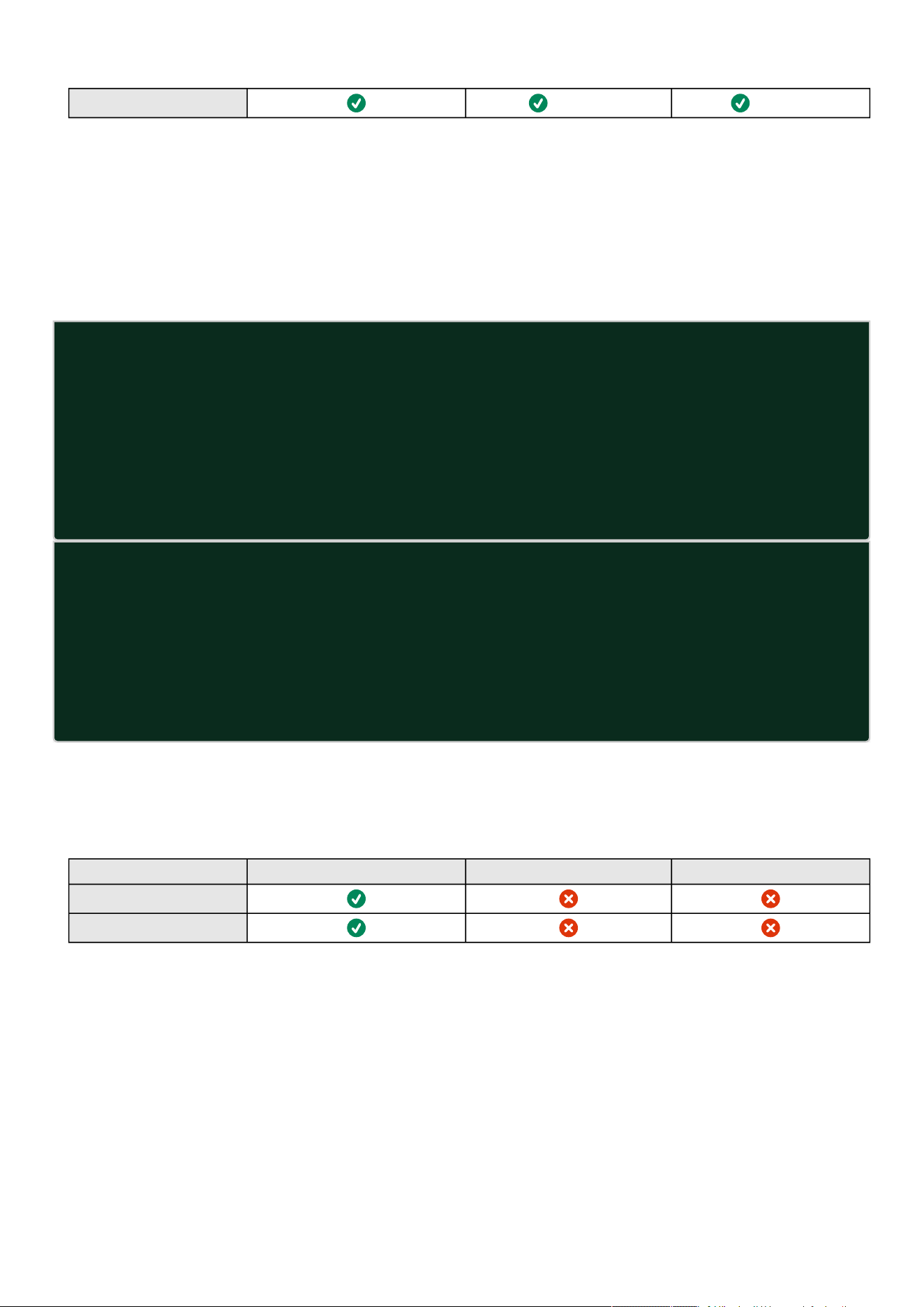
CLI
Information – 237
netconf
(read-only) (read-only)
7.7.10 ping and ping6
7.7.10.1 Description
Ping and ping6 utilities are used to test network connection.
7.7.10.2 Help
ping
The ping utility uses the ICMP protocol's mandatory ECHO_REQUEST datagram
to elicit an ICMP ECHO_RESPONSE from a host or gateway. ECHO_REQUEST
datagrams (``pings'') have an IP and ICMP header, followed by a ``struct
timeval'' and then an arbitrary number of ``pad'' bytes used to fill out
the packet.
-c Specify the number of echo requests to be sent
-h Specify maximum number of hops
<Hostname or IP> Host name or IP address
ping6
The ping6 utility uses the ICMP protocol's mandatory ECHO_REQUEST datagram
to elicit an ICMP ECHO_RESPONSE from a host or gateway. ECHO_REQUEST
datagrams (``pings'') have an IP and ICMP header, followed by a ``struct
timeval'' and then an arbitrary number of ``pad'' bytes used to fill out
the packet.
-c Specify the number of echo requests to be sent
<IPv6 address> IPv6 address
7.7.10.3 Specifics
7.7.10.4 Access rights per profiles
Administrator Operator Viewer
ping
ping6
7.7.11 reboot
7.7.11.1 Description
Tool to Reboot the card.

CLI
Information – 238
•
•
•
•
•
7.7.11.2 Help
Usage: reboot [OPTION]
<cr> Reboot the card
--help Display help
--withoutconfirmation Reboot the card without confirmation
7.7.11.3 Specifics
7.7.11.4 Access rights per profiles
Administrator Operator Viewer
reboot
7.7.12 save_configuration | restore_configuration
7.7.12.1 Description
Save_configuration and restore_configuration are using JSON format to save and restorecertain part of the configuration of the
card.
7.7.12.2 Help
save_configuration -h
save_configuration: print the card configuration in JSON format to standard output.
restore_configuration -h
restore_configuration: restore the card configuration from a JSON-formatted standard input.
7.7.12.3 Examples of usage
7.7.12.3.1 From a linux host:
Save over SSH:sshpass -p $PASSWORD ssh $USER@$CARD_ADDRESS save_configuration -p $PASSPHRASE> $FILE
Restore over SSH:cat $FILE | sshpass -p $PASSWORD ssh $USER@$CARD_ADDRESS restore_configuration -p $PASSPHRASE
7.7.12.3.2 From a Windows host:
Save over SSH:plink $USER@$CARD_ADDRESS -pw$PASSWORD -batch save_configuration -p $PASSPHRASE > $FILE
Restore over SSH:type $FILE | plink $USER@$CARD_ADDRESS -pw $PASSWORD -batch restore_configuration -p $PASSPHRASE
(Require plink tools from putty)
Where:
$USER is user name (the user shall have administrator profile)
$PASSWORD is the user password
$PASSPHRASE is any passphrase to encrypt/decrypt sensible data.
$CARD_ADDRESS is IP or hostname of the card
$FILE is a path to the JSON file (on your host computer) where the configuration is saved or restored.

CLI
Information – 239
•
7.7.12.4 Specifics
7.7.12.5 Access rights per profiles
Administrator Operator Viewer
save_configuration
restore_configuration
7.7.13 sanitize
7.7.13.1 Description
Sanitize command to return card to factory reset configuration.
7.7.13.2 Access
Administrator
7.7.13.3 Help
sanitize
-h, --help Display help page
--withoutconfirmation Do factory reset of the card without confirmation
<cr> Do factory reset of the card
7.7.13.4 Access rights per profiles
Administrator Operator Viewer
sanitize
7.7.14 ssh-keygen
7.7.14.1 Description
Command usedfor generating the ssh keys.
7.7.14.2 Help
ssh-keygen
-h, --help Display help
<cr> Renew SSH keys

CLI
Information – 240
7.7.14.3 Specifics
7.7.14.4 Access rights per profiles
Administrator Operator Viewer
ssh-keygen
7.7.15 time
7.7.15.1 Description
Command used to displayor changetime and date.
7.7.15.2 Help
For Viewer and Operator profiles:
time -h
Usage: time [OPTION]...
Display time and date.
-h, --help display help page
-p, --print display date and time in YYYYMMDDhhmmss format
For Administrator profile:
time -h
Usage: time [OPTION]...
Display time and date, change time and date.
-h, --help display help page
-p, --print display date and time in YYYYMMDDhhmmss format
-s, --set <mode>
Mode values:
- set date and time (format YYYYMMDDhhmmss)
manual <date and time>
- set preferred and alternate NTP servers
ntpmanual <preferred server> <alternate server>
- automatically set date and time
ntpauto
Examples of usage:
-> Set date 2017-11-08 and time 22:00
time --set manual 201711082200
-> Set preferred and alternate NTP servers
time --set ntpmanual fr.pool.ntp.org de.pool.ntp.org
7.7.15.3 Examples of usage
-> Set date 2017-11-08 and time 22:00
time --set manual 201711082200
-> Set preferred and alternate NTP servers
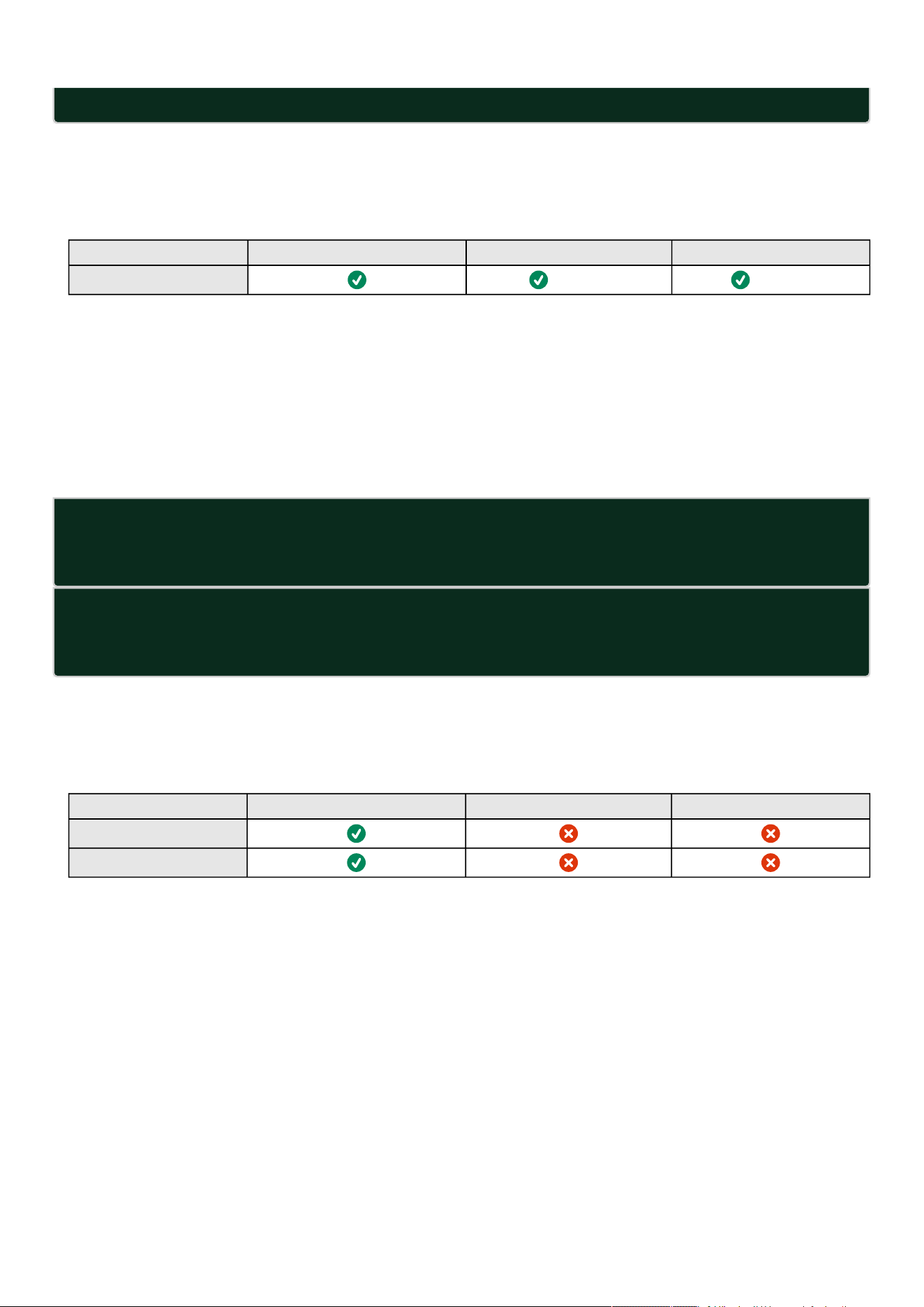
CLI
Information – 241
•
•
•
time --set ntpmanual fr.pool.ntp.org de.pool.ntp.org
7.7.15.4 Specifics
7.7.15.5 Access rights per profiles
Administrator Operator Viewer
time
(read-only) (read-only)
7.7.16 traceroute and traceroute6
7.7.16.1 Description
Traceroute and traceroute6 utilities are for checking the configuration of the network.
7.7.16.2 Help
traceroute
-h Specify maximum number of hops
<Hostname or IP> Remote system to trace
traceroute6
-h Specify maximum number of hops
<IPv6 address> IPv6 address
7.7.16.3 Specifics
7.7.16.4 Access rights per profiles
Administrator Operator Viewer
traceroute
traceroute6
7.7.17 whoami
7.7.17.1 Description
whoami displays current user information:
Username
Profile
Realm

CLI
Information – 242
1.
a.
b.
2.
a.
b.
c.
d.
3.
a.
i.
7.7.17.2 Specifics
7.7.17.3 Access rights per profiles
Administrator Operator Viewer
whoami
7.7.18 email-test
7.7.18.1 Description
mail-test sends test email to troubleshoot SMTP issues.
7.7.18.2 Help
Usage: email-test <command> ...
Test SMTP configuration.
Commands:
email-test -h, --help, Display help page
email-test -r, --recipient <recipient_address>
Send test email to the
<recipient_address> Email address of the recipient
7.7.18.3 Specifics
7.7.18.4 Access rights per profiles
Administrator Operator Viewer
email-test
7.7.19 systeminfo_statistics
7.7.19.1 Description
Displays the following system information usage:
CPU
usage : %
upSince: date since the system started
Ram
total: MB
free: MB
used: MB
tmpfs: temporary files usage (MB)
Flash
user data
total: MB

CLI
Information – 243
ii.
iii.
free: MB
used: MB
7.7.19.2 Help
systeminfo_statistics
Display systeminfo statistics
-h, --help Display the help page.
7.7.19.3 Specifics
7.7.19.4 Access rights per profiles
Administrator Operator Viewer
systeminfo_statistics
7.7.20 certificates
7.7.20.1 Description
Allows to manage certificates through the CLI.
7.7.20.2 Help
certificates <target> <action> <service_name>
<target> :
- local
<action> :
- print: provides a given certificate detailed information.
- revoke: revokes a given certificate.
- export: returns a given certificate contents.
- import: upload a given certificate for the server CSR. This will replace the CSR
with the certificate given.
- csr: get the server CSR contents. This will create the CSR if not already existing.
<service_name>: mqtt/syslog/webserver
7.7.20.3 Examples of usage
7.7.20.3.1 From a linux host:
printover SSH:sshpass -p $PASSWORD ssh $USER@$CARD_ADDRESS certificates local print $SERVICE_NAME
revoke over SSH:sshpass -p $PASSWORD ssh $USER@$CARD_ADDRESS certificates localrevoke $SERVICE_NAME
exportover SSH:sshpass -p $PASSWORD ssh $USER@$CARD_ADDRESS certificates localexport $SERVICE_NAME
importover SSH:cat$FILE | sshpass -p $PASSWORD ssh $USER@$CARD_ADDRESS certificates localimport $SERVICE_NAME
csr over SSH:sshpass -p $PASSWORD ssh $USER@$CARD_ADDRESS certificates localcsr mqtt
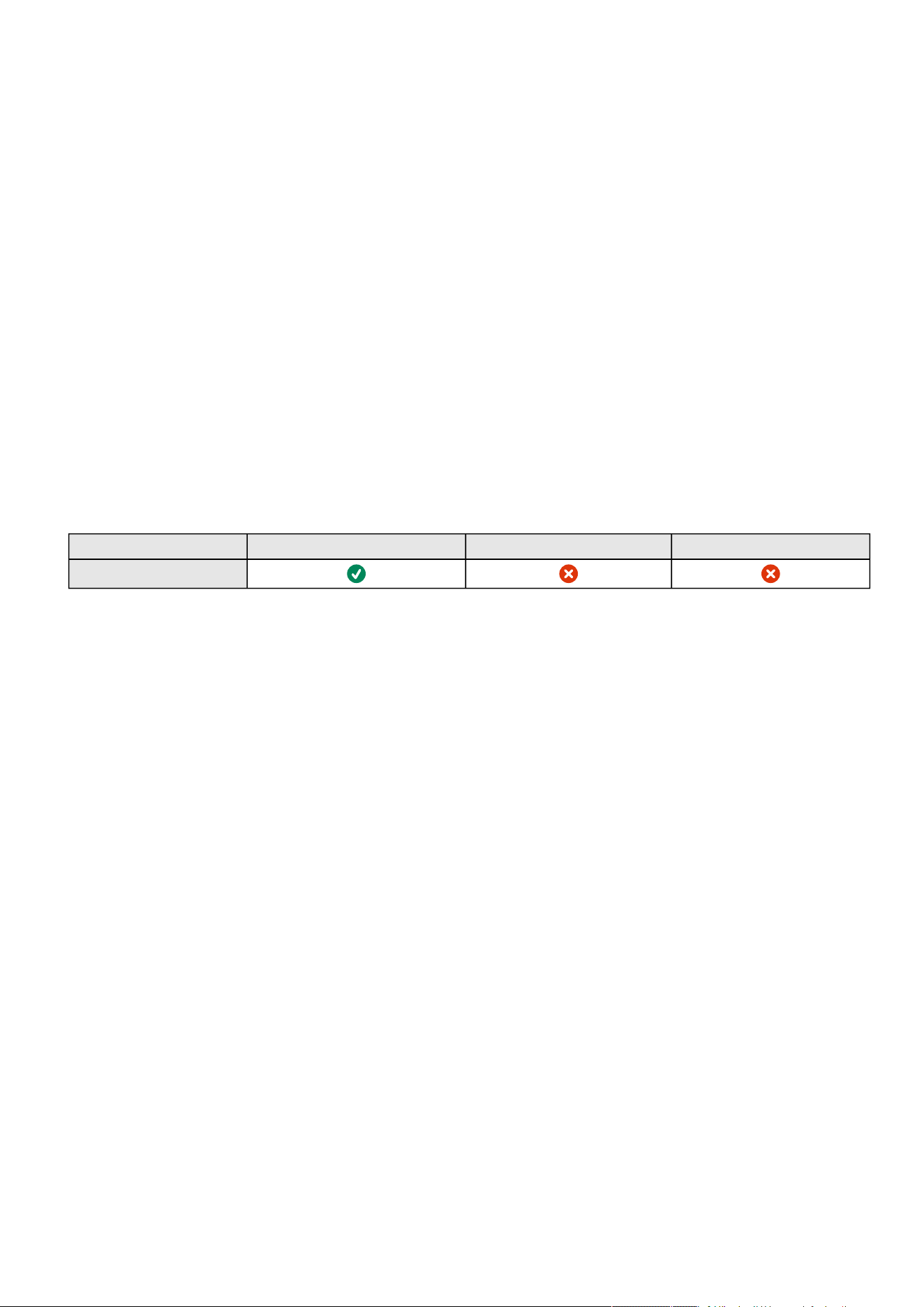
Legal information
Information – 244
•
•
•
•
•
•
•
•
•
•
•
•
•
•
7.7.20.3.2 From a Windows host:(plink tools from putty is required)
print over SSH:plink $USER@$CARD_ADDRESS -pw$PASSWORD -batch certificates local print $SERVICE_NAME
revoke over SSH:plink $USER@$CARD_ADDRESS -pw $PASSWORD -batch certificates localrevoke $SERVICE_NAME
export over SSH:plink $USER@$CARD_ADDRESS -pw$PASSWORD -batch certificates localexport $SERVICE_NAME
import over SSH:type $FILE | plink $USER@$CARD_ADDRESS -pw $PASSWORD -batch certificates localimport
$SERVICE_NAME
csrover SSH:plink $USER@$CARD_ADDRESS -pw $PASSWORD -batch certificates localcsr mqtt
7.7.20.3.3 Where:
$USER is user name (the user shall have administrator profile)
$PASSWORD is the user password
$PASSPHRASE is any passphrase to encrypt/decrypt sensible data.
$CARD_ADDRESS is IP or hostname of the card
$FILE is a certificate file
$SERVICE_NAME is the name one of the following services : mqtt/ syslog / webserver.
7.7.20.4 Specifics
7.7.20.5 Access rights per profiles
Administrator Operator Viewer
certificates
7.8 Legal information
This Network Module includes software components that are either licensed under various open source license, or under a
proprietary license.
For more information, see to the legal Information link from the main user interface in the footer.
7.8.1 Availability of Source Code
The source code of open source components that are made available by their licensors may be obtained upon written express
request by contacting[email protected].Eatonreserves the right to charge minimal administrative costs, in
compliance with the terms of the underlying open source licenses, when the situation requires.
7.8.2 Notice for Open Source Elements
This product includes software released under BSD or Apache v2 licenses, and developed by various projects, peoples and entities,
such as, but not limited to:
* the Regents of the University of California, Berkeley and its contributors,
* the OpenEvidence Project,
* Oracle and/or its affiliates,
* Mike Bostock,
* JS Foundation and other contributors,
* 2011-2014 Novus Partners, Inc.
This product includes software developed by the OpenSSL Project for use in the OpenSSL Toolkit. (www.openssl.org/).
This product includes cryptographic software written by Eric Young ([email protected]).
This product includes software released under MIT license, and developed by various projects, peoples and entities, such as, but
not limited to:
* Google, Inc.,
* the AngularUI Team

Legal information
Information – 245
•
•
•
•
•
•
•
•
•
•
•
•
•
•
•
•
* Lucas Galfasó
* nerv
* Angular
* Konstantin Skipor
* Filippo Oretti, Dario Andrei
* The angular-translate team and Pascal Precht,
* Twitter, Inc.
* Zeno Rocha
* Kristopher Michael Kowal and contributors
* JS Foundation and other contributors
* Jonathan Hieb
* Mike Grabski
* Sachin N.
This product includes contents released under Creative Commons Attribution 4.0, Creative Commons Attribution-ShareAlike 3.0
Unported and SIL Open Font License licenses, and created by:
* IcoMoon
* Dave Gandy
* Stephen Hutchings and the Typicons team.
In order to access the complete and up to date copyright information, licenses, and legal disclaimers, see the Legal Information
pages, available from the HTML user interface of the present product.
7.8.3 Notice for our proprietary (i.e. non-Open source) elements
Copyright © 2020 Eaton. This firmware is confidential and licensed under Eaton Proprietary License (EPL or EULA).
This firmware is not authorized to be used, duplicated, or disclosed to anyone without the prior written permission of Eaton.
Limitations, restrictions and exclusions of the Eaton applicable standard terms and conditions, such as its EPL and EULA, apply.

Acronyms and abbreviations
Information – 246
7.9 Acronyms and abbreviations
AC:Alternating current.
ATS: Automatic transfer switch is an electricalswitchthat switches a load between two sources.
AVR:Automatic Voltage Regulation provides stable voltage to keep equipment running in the optimal range.
BBDM:Broadcast Management Device (BACnet).
BMS: A Battery Management System is any electronic system that manages li-ion battery.
bps: bit per second
BOM:In Syslog,placing an encoded Byte Order Markat the start of a text stream can indicates that the text is Unicode and identify
the encoding scheme used.
CA: Certificate Authority
CLI: Command Line Interface.
Aim is to interact with the Network Module by using commandsin the form of successive lines of text (command lines).
CSR: Certificate Signing Request
DC:Direct current.
DCC:Device Communication Control (BACnet).
DN:Distinguished Name (LDAP).
DHCPv6: The Dynamic Host Configuration Protocol version 6 is a network protocol for configuring Internet Protocol version 6 (IPv6)
hosts with IP addresses, IP prefixes and other configuration data required to operate in an IPv6 network.
It is the IPv6 equivalent of the Dynamic Host Configuration Protocol for IPv4.
DNS: The Domain Name System is a hierarchical decentralized naming system for computers, services, or other resources
connected to the Internet or a private network.
DST: The daylight saving time.
EMP: Environmental monitoring probe
GID: Group Identifier is a numeric value used to represent a specific group (LDAP).
HTTPS:HTTPS consists of communication over Hypertext Transfer Protocol (HTTP) within a connection encrypted by Transport
Layer Security (TLS).
IPP:Intelligent Power Protector is a web-based application that enables administrators to manage an Devices from a browser-based
management console. Administrators can monitor, manage, and control a single Device (UPS, ATS, ePDU) locally and remotely. A
familiar browser interface provides secure access to the Device Administrator Software and Device Client Software from anywhere
on the network. Administrators may configure power failure settings and define UPS load segments for maximum uptime of critical
servers.The UPS can also be configured to extend runtimes for critical devices during utility power failures. For most UPSs, the
receptacles on the rear panel are divided into one or more groups, called load segments, which can be controlled independently. By
shutting down a load segment that is connected to less critical equipment, the runtime for more critical equipment is extended,
providing additional protection.
IPv4:Internet Protocol version 4 is the fourth version of the Internet Protocol (IP).
IPv6:Internet Protocol version 6 is the most recent version of the Internet Protocol (IP).
JSON:JavaScript Object Notation is an open-standard file format that uses human-readable text to transmit data objects consisting
of attribute–value pairs and array data types.
kVA:kilovolt-ampere.
LAN:A LAN is a local area network, a computer network covering a small local area, such as a home or office.
LDAP:The Lightweight Directory Access Protocol is an industry standard application protocol for accessing and maintaining
distributed directory information services over an Internet Protocol.

Acronyms and abbreviations
Information – 247
MAC:A media access control address of a computer is a unique identifier assigned to network interfaces for communications at
the data link layer of a network segment.
MIB:A management information base is a database used for managing the entities in a communication network. Most often
associated with the Simple Network Management Protocol (SNMP).
NTP:Network Time Protocol is a networking protocol for clock synchronization between computer systems.
PDU/ePDU: A power distribution unit (PDU) is a device fitted with multiple outputs designed to distribute electric power, especially
to racks of computers and networking equipment located within a data center.
P/N:Part number.
RTC:Real time clock.
RTU: Remote Terminal Unit
S/N:Serial number.
SMTP:Simple Mail Transfer Protocol is an Internet standard for electronic mail (email) transmission.
SNMP:Simple Network Management Protocol is an Internet-standard protocol for collecting and organizing information about
managed devices on IP networks and for modifying that information to change device behavior.
SSH:Secure Shell is a cryptographic network protocol for operating network services securely over an unsecured network.
SSL:Secure Sockets Layer, is a cryptographic protocol used for network traffic.
TCP: Transmission Control Protocol
TLS:Transport Layer Security is cryptographic protocol that provide communications security over a computer network.
TFTP:Trivial File Transfer Protocol is a simple lockstep File Transfer Protocol which allows a client to get a file from or put a file onto
a remote host.
UID:User identifier (LDAP).
UTC:Coordinated Universal Time is the primary time standard by which the world regulates clocks and time.
UPS:An uninterruptible power supply is an electrical apparatus that provides emergency power to a load when the input power
source or mains power fails.
A UPS is typically used to protect hardware such as computers, data centers, telecommunication equipment or other electrical
equipment where an unexpected power disruption could cause injuries, fatalities, serious business disruption or data loss.

Acronyms and abbreviations
Information – 248

Action not allowed in Control/Schedule/Power outage policy
Troubleshooting – 249
8 Troubleshooting
8.1 Action not allowed in Control/Schedule/Power outage policy
8.1.1 Symptom
Below message is displayed when you access the Control, Schedule or Power outage policy page.
This action is not allowed by the UPS.
To enable it, please refer to the user manual of the UPS and its instructions on how to configure the UPS settings and allow remote
commands.
8.1.2 Possible Cause
1- Remote commands are not allowed due to the UPS configuration (see the action below)
2- The UPS does not support remote commands.
8.1.3 Action
Refer to the UPS user manual and its instruction on how to configure the UPS settings and allow remote commands.
Example: UPS menu Settings>>>ON/OFF settings>>>Remote command>>>Enable.
8.2 Card wrong timestamp leads to "Full acquisition has failed"
error message on Software
8.2.1 Symptoms:
IPP/IPMshows the error message"The full data acquisition has failed" even if the credentials are correct.
8.2.2 Possible cause:
The Network module timestamp is not correct.
Probably the MQTT certificate is not valid at Network module date.
8.2.3 Action:
Set the right date, time and timezone. If possible, use a NTP server, refer to Contextual help>>>Settings>>>General>>>System
details>>>Time & date settings section.
8.3 Client server is not restarting
8.3.1 Symptom
Utility power has been restored, the UPS and its load segments are powered on, but the Client server does not restart.
8.3.2 Possible Cause
The “Automatic Power ON” server setup setting might be disabled.

EMP detection fails at discovery stage
Troubleshooting – 250
8.3.3 Action
In the server system BIOS, change the setting for Automatic Power ON to "Enabled".
8.4 EMP detection fails at discovery stage
In the Network Module,inContextual help>>>Environment>>>Commissioning/Status, EMPs are missing in the Sensor
commissioning table.
8.4.1 Symptom #1
The EMPs green RJ45 LED (FROM DEVICE) is not ON.
8.4.1.1 Possible causes
The EMPs are not powered by the Network module.
8.4.1.2 Action #1-1
Launch again the discovery, if it is still not ok, go to Action #1-2.
8.4.1.3 Action #1-2
1- Check the EMPs connection and cables.
Refer to the sectionsServicing the EMP>>>Installing the EMP>>>Cabling the first EMP to the deviceandServicing the
EMP>>>Installing the EMP>>>Daisy chaining 3 EMPs.
2- Disconnect and reconnect the USB to RS485 cable.
3-Launch the discovery, if it is still not ok, go to Action #1-3.
8.4.1.4 Action #1-3
1- Reboot the Network module.
2-Launch the discovery.
8.4.2 Symptom #2
The EMPs orange RJ45 LEDs are not blinking.
8.4.2.1 Possible causes
C#1: the EMP address switches are all set to 0.
C#2: the EMPs are daisy chained, the Modbus address is the same on the missing EMPs.
8.4.2.2 Action #2-1
1- Change the address of the EMPs to have different address and avoid all switches to 0.
Refer to the sectionServicing the EMP>>>Defining EMPs address and termination>>>Manual addressing.
2- Disconnect and reconnect the USB to RS485 cable. The address change is only taken into account after an EMP power-up.
3-Launch the discovery,if it is still not ok, go to Action #2-2.
8.4.2.3 Action #2-2
1- Reboot the Network module.

How do I log in if I forgot my password?
Troubleshooting – 251
•
•
•
•
•
•
•
•
•
•
•
Refer to the sectionContextual help>>>Maintenance>>>Services>>>Reboot.
2-Launch the discovery.
8.5 How do I log in if I forgot my password?
8.5.1 Action
Askyour administrator for password initialization.
If you are the mainadministrator, yourpasswordcan be reset manually by following steps described in theServicing the
Network Management Module>>>Recovering main administrator password.
8.6 Software is not able to communicate with the Network
module
8.6.1 Symptoms
In the Network Module,inContextual help>>>Protection>>>Agent list>>>Agent list table, agent is showing "Lost" as a
status.
In the Network Module,inContextual help>>>Settings>>>Certificate>>>Trusted remote certificates, the status of
theProtected applications (MQTT) is showing"Not valid yet".
IPP/IPMshows "The authentication has failed", "The notifications reception encountered error".
8.6.2 Possible cause
TheIPP/IPMcertificate is not yet valid for the Network Module.
Certificates ofIPP/IPMand the Network Module are not matching so that authentication and encryption of connections between
the Network Module and the shutdown agents is not working.
8.6.3 Setup
IPP/IPMis started.
Network module is connected to the UPS and to the network.
8.6.4 Action #1
Check if theIPP/IPMcertificate validity for the Network Module.
STEP 1:Connect to the Network Module
On a network computer, launch a supported web browser. The browser window appears.
In the Address/Location field, enter:https://xxx.xxx.xxx.xxx/where xxx.xxx.xxx.xxx is the static IP address of the Network
Module.
The log in screen appears.
Enter the user name in the User Name field.
Enter the password in the Password field.
ClickLogin. The Network Module web interface appears.
STEP 2:Navigate toSettings/Certificatespage
STEP 3:In theTrusted remote certificatessection, check the status of theProtected applications (MQTT).
If it is "Valid"go to Action#2 STEP 2, if it is "Not yet valid", time of the need to be synchronized withIPP/IPM.
STEP 4:Synchronize the time of the Network Module withIPP/IPMand check that the status of theProtected applications
(MQTT)is now valid.

LDAP configuration/commissioning is not working
Troubleshooting – 252
•
•
•
•
•
•
•
•
•
•
Communication will then recover, if notgo to Action#2 STEP 2.
8.6.5 Action #2
Pair agent to the Network Module with automatic acceptance (recommended in case the installation is done in a secure and trusted
network).
STEP 1:Connect to the Network Module.
On a network computer, launch a supported web browser. The browser window appears.
In the Address/Location field, enter:https://xxx.xxx.xxx.xxx/where xxx.xxx.xxx.xxx is the static IP address of the Network
Module.
The log in screen appears.
Enter the user name in the User Name field.
Enter the password in the Password field.
ClickLogin. The Network Module web interface appears.
STEP 2:Navigate toProtection/Agents listpage.
STEP 3:In thePairing with shutdown agentssection, select the time to accept new agents and press theStartbutton
andContinue. During the selected timeframe, new agent connections to the Network Module are automatically trusted and
accepted.
STEP 4:Action on the agent(IPP/IPM)while the time to accepts new agents is running on the Network Module
Remove theNetwork module certificate file(s) *.0that is (are) located in the folderEaton\IntelligentPowerProtector\configs\tls.
8.7 LDAP configuration/commissioning is not working
Refer to the sectionServicing the Network Management Module>>>Commissioning/Testing LDAP.
8.8 Modbus communication doesn't work
8.8.1 Symptoms
Communication doesn't work
8.8.2 Possible cause
Incorrect communication parameters.
Verify that the communication parameters are set to the desired settings.For Modbus TCP configuration refer to the
sectionContextual help>>>Settings>>>Modbus>>>Modbus TCP.
For Modbus RTU configuration refer to the sectionContextual help>>>Settings>>>Modbus>>>Modbus RTU.
RS-485 communication lines are reversed
For two-wire networks refer to the sectionInstalling the Network Management Module>>>Wiring the RS-485 Modbus RTU
terminal>>>Two-wire networks.
For four-wire networks refer to the sectionInstalling the Network Management Module>>>Wiring the RS-485 Modbus RTU
terminal>>>Four-wire networks.
If the Modbus Card is the last device installed in the network chain or the length of the network cable is excessive,
termination needs to be enabled.
For manual pairing (maximum security), go toServicing the Network Management Module
>>>Pairing agent to the
Network Module
section and then go to STEP 2, item 1.
Refer to the section Servicing the Network Management Module>>>Configuring Modbus to get configuration and
testing information.


Password change in My profile is not working
Troubleshooting – 254
8.9 Password change in My profile is not working
8.9.1 Symptoms
The password change shows "
Invalid credentials
" when I try to change my password in My profile menu:
8.9.2 Possible cause
The password has already been changed once within a day period.
8.9.3 Action
Let one day between your last password change and retry.
8.10 SMTP server configuration does not work with Gmail
8.10.1 Symptom
xxxx
8.10.2 Cause
xxxx
8.10.3 Action
xxxx
8.11 SNMPv3 password management issue with Save and
Restore
8.11.1 Affected FW versions
This issue affects SNMPconfigurationdone on versions prior to 1.7.0 when applied to versions 1.7.0 or above.
8.11.2 Symptom
SNMPv3 connectivity is not properly working after a restore settings on a 1.7.0 version or above.
8.11.3 Cause
The SNMPv3 wasconfiguredprior to 1.7.0.
In that case, SNMPv3 configuration is not well managed by the Save and by the Restore settings.

The alarm list has been cleared after an upgrade
Troubleshooting – 255
8.11.4 Action
Reconfigureyour SNMPv3 users and passwords on versions 1.7.0 or above and Save the settings.
The SNMPv3 configuration can then be Restored.
8.12 The alarm list has been cleared after an upgrade
8.12.1 Symptom
After a FW upgrade, the alarm list has been cleared and is now empty.
8.12.2 Action
The alarm list has been saved on a csv file and can be retrieved using Rest API calls.
8.12.2.1 Authenticate:
curl --location --request POST 'https://{{domain}}/rest/mbdetnrs/1.0/oauth2/token' \
--header 'Content-Type: application/json' \
--data-raw '{ "username":"admin", "password":"supersecretpassword", "grant_type":"password",
"scope":"GUIAccess" }'
8.12.2.2 Get Alarm Log Backup:
curl --location --request GET 'https://{{domain}}/rest/mbdetnrs/1.0/alarmService/actions/
downloadBackup' \
--header 'Authorization: Bearer {{access_token}}'
8.13 The Network Module fails to boot after upgrading the
firmware
8.13.1 Possible Cause
1- The IP address has changed.
2- The Network module LED shows solid red after the upgrade.
3- The first boot after the upgrade takes a longer time.
Note:If theapplication is corrupt, due to an interruptionwhile flashing the firmware for example, the boot will be done on previous
firmware.
8.13.2 Action
1- Recover the IP address and connect to the card.
2- Reset the Network module by using the Restart button on the front panel.
3- Wait until the Network module LED shows flashing green.
Refer to Installing the Network Management Module>>>Accessing the Network Module>>>Finding and setting the IP address
section.

Web user interface is not up to date after a FW upgrade
Troubleshooting – 256
•
•
•
8.14 Web user interface is not up to date after a FW upgrade
8.14.1 Symptom
After an upgrade:
The Web interface is not up to date
New features of the new FW are not displayed
An infinite spinner is displayed on a tile
8.14.1.1 Possible causes
The browser is displaying the Web interface through the cache that contains previous FW data.
8.14.1.2 Action
Empty the cache of your browser using F5 or CTRL+F5.