
UPS Industrial Gateway Card
INDGW-M2
User's Guide
English
11/18/2019
1.7.4


Eaton is a registered trademark of Eaton Corporation or its subsidiaries and affiliates.
Phillips and Pozidriv are a registered trademarks of Phillips Screw Company.
National Electrical Code and NEC are registered trademarks of National Fire Protection Association, Inc.
Microsoft®, Windows®, and Windows Server® are either registered trademarks or trademarks of Microsoft Corporation in the United States and/or other countries.
UNIX® is a registered trademark of The Open Group.
Linux® is the registered trademark of Linus Torvalds in the U.S. and other countries.
VMware is a registered trademark or trademark of VMware, Inc. in the United States and/or other jurisdictions.
Google™ is a trademark of Google Inc.
All other trademarks are properties of their respective companies.
©Copyright 2019 Eaton Corporation. All rights reserved.
No part of this document may be reproduced in any way without the express written approval of Eaton Corporation.

1 Table of Contents
1TABLE OF CONTENTS.....................................................................................................................................4
2CONTEXTUAL HELP......................................................................................................................................13
2.1Login page.........................................................................................................................................................................13
2.1.1Logging in for the first time.........................................................................................................................................13
2.1.2Troubleshooting login issues.......................................................................................................................................13
2.2Home................................................................................................................................................................................. 13
2.2.1Menu structure............................................................................................................................................................ 14
2.2.2Energy flow diagram.................................................................................................................................................... 15
2.2.2.1Line interactive........................................................................................................................................................ 15
2.2.2.2Online...................................................................................................................................................................... 17
2.2.3Top bar......................................................................................................................................................................... 19
2.2.4Details.......................................................................................................................................................................... 20
2.2.5Show measures........................................................................................................................................................... 20
2.2.5.1Example #1.............................................................................................................................................................. 20
2.2.5.2Example #2.............................................................................................................................................................. 20
2.2.6Outlet status................................................................................................................................................................ 21
2.2.7Active Alarms..............................................................................................................................................................21
2.3Alarms...............................................................................................................................................................................21
2.3.1Alarm sorting............................................................................................................................................................... 21
2.3.2Alarm details................................................................................................................................................................ 21
2.3.3Alarm paging................................................................................................................................................................ 22
2.3.4Alarm export................................................................................................................................................................22
2.3.5Clear alarm logs...........................................................................................................................................................22
2.3.6Alarm list with codes...................................................................................................................................................22
2.4Settings.............................................................................................................................................................................23
2.4.1General........................................................................................................................................................................ 23
2.4.1.1Location...................................................................................................................................................................23
2.4.1.2Contact.................................................................................................................................................................... 23
2.4.1.3System name..........................................................................................................................................................23
2.4.1.4Default settings parameters and limitations............................................................................................................ 23
2.4.2Date & Time................................................................................................................................................................23
2.4.2.1Manual:Manually entering the date and time......................................................................................................... 24
2.4.2.2Dynamic (NTP):Synchronizing the date and time with an NTP server.................................................................... 24
2.4.2.3Default settings parameters and limitations............................................................................................................ 24
2.4.3Users........................................................................................................................................................................... 25
2.4.3.1Password strength rules.......................................................................................................................................... 25
2.4.3.2Account expiration................................................................................................................................................... 25
2.4.3.3Session expiration................................................................................................................................................... 26
2.4.3.4Local users table...................................................................................................................................................... 26
2.4.3.5LDAP.......................................................................................................................................................................29
2.4.3.6RADIUS...................................................................................................................................................................32
2.4.3.7Default settings parameters and limitations............................................................................................................ 35
2.4.4Network....................................................................................................................................................................... 35
2.4.4.1LAN.......................................................................................................................................................................... 35
2.4.4.2IPv4.......................................................................................................................................................................... 35
2.4.4.3Domain.................................................................................................................................................................... 37
2.4.4.4IPv6.......................................................................................................................................................................... 38
2.4.4.5Default settings parameters and limitations............................................................................................................ 40

2.4.5Protocols...................................................................................................................................................................... 40
2.4.5.1HTTPS...................................................................................................................................................................... 40
2.4.5.2Syslog......................................................................................................................................................................40
2.4.5.3Default settings parameters and limitations............................................................................................................ 41
2.4.6SNMP.......................................................................................................................................................................... 41
2.4.6.1SNMP tables............................................................................................................................................................ 42
2.4.6.2Trap receivers.........................................................................................................................................................44
2.4.6.3Actions.................................................................................................................................................................... 45
2.4.6.4Default settings parameters and limitations............................................................................................................ 46
2.4.7Modbus.......................................................................................................................................................................46
2.4.7.1Modbus RTU...........................................................................................................................................................46
2.4.7.2Modbus TCP............................................................................................................................................................ 47
2.4.7.3Mapping configuration............................................................................................................................................. 47
2.4.7.4Default settings parameters and limitations............................................................................................................ 48
2.4.8Certificates..................................................................................................................................................................48
2.4.8.1Local certificates...................................................................................................................................................... 48
2.4.8.2Certificate authorities (CA)....................................................................................................................................... 51
2.4.8.3Pairing with clients.................................................................................................................................................. 52
2.4.8.4Trusted remote certificates..................................................................................................................................... 52
2.4.8.5Default settings parameters and limitations............................................................................................................ 53
2.4.9Email............................................................................................................................................................................ 53
2.4.9.1Email sending configuration.................................................................................................................................... 53
2.4.9.2Default settings parameters and limitations............................................................................................................ 56
2.4.10My preferences........................................................................................................................................................... 56
2.4.10.1Profile......................................................................................................................................................................57
2.4.10.2Temperature............................................................................................................................................................57
2.4.10.3Date format............................................................................................................................................................. 58
2.4.10.4Time format.............................................................................................................................................................58
2.4.10.5Language................................................................................................................................................................59
2.4.10.6Default settings parameters and limitations............................................................................................................ 59
2.5Meters...............................................................................................................................................................................59
2.5.1Power.......................................................................................................................................................................... 59
2.5.1.1Input........................................................................................................................................................................59
2.5.1.2Output.....................................................................................................................................................................60
2.5.2Battery.........................................................................................................................................................................60
2.5.2.1Overview................................................................................................................................................................. 60
2.5.2.2Details...................................................................................................................................................................... 60
2.5.2.3Test.......................................................................................................................................................................... 60
2.5.3Measure logs............................................................................................................................................................... 61
2.5.3.1Configuration........................................................................................................................................................... 61
2.5.3.2Measure logs........................................................................................................................................................... 61
2.5.3.3Default settings parameters and limitations............................................................................................................ 62
2.6Controls............................................................................................................................................................................. 62
2.6.1UPS.............................................................................................................................................................................. 62
2.6.1.1Entire UPS............................................................................................................................................................... 62
2.6.2Outlets......................................................................................................................................................................... 63
2.6.2.1Group 1/ Group 2.....................................................................................................................................................63
2.7Protection.......................................................................................................................................................................... 64
2.7.1Scheduled shutdowns.................................................................................................................................................64
2.7.1.1Scheduled shutdowns table.................................................................................................................................... 64
2.7.1.2Actions..................................................................................................................................................................... 64
2.7.2Agent list.....................................................................................................................................................................65
2.7.2.1Pairing with shutdown agents.................................................................................................................................65
2.7.2.2Agent list table......................................................................................................................................................... 65

2.7.2.3Actions..................................................................................................................................................................... 66
2.7.3Agent settings............................................................................................................................................................. 66
2.7.3.1Agent shutdown sequence timing.......................................................................................................................... 66
2.7.3.2Actions..................................................................................................................................................................... 67
2.7.3.3Examples.................................................................................................................................................................67
2.7.4Power outage policy....................................................................................................................................................67
2.7.4.1On power outage..................................................................................................................................................... 68
2.7.4.2On low battery warning...........................................................................................................................................72
2.7.4.3When utility comes back......................................................................................................................................... 73
2.8Card................................................................................................................................................................................... 73
2.8.1System information..................................................................................................................................................... 73
2.8.1.1Identification............................................................................................................................................................73
2.8.1.2Firmware information.............................................................................................................................................. 74
2.8.2Resources.................................................................................................................................................................... 74
2.8.2.1Processor................................................................................................................................................................. 74
2.8.2.2Memory...................................................................................................................................................................74
2.8.2.3Storage.................................................................................................................................................................... 75
2.8.3System logs................................................................................................................................................................. 75
2.8.4Administration.............................................................................................................................................................76
2.8.4.1Network module firmware...................................................................................................................................... 76
2.8.4.2Sanitization.............................................................................................................................................................. 77
2.8.4.3Reboot.....................................................................................................................................................................78
2.8.4.4Maintenance............................................................................................................................................................ 78
2.8.4.5Settings...................................................................................................................................................................79
2.8.5Commissioning (sensors)............................................................................................................................................ 81
2.8.5.1Sensors commissioning table.................................................................................................................................. 81
2.8.5.2Actions..................................................................................................................................................................... 81
2.8.5.3Note:........................................................................................................................................................................ 84
2.9Sensors.............................................................................................................................................................................. 84
2.9.1Status (sensors)........................................................................................................................................................... 84
2.9.1.1Temperature table................................................................................................................................................... 84
2.9.1.2Humidity table......................................................................................................................................................... 84
2.9.1.3Dry contacts table.................................................................................................................................................... 85
2.9.2Alarm configuration (sensors)...................................................................................................................................... 85
2.9.2.1Temperature............................................................................................................................................................85
2.9.2.2Humidity.................................................................................................................................................................. 86
2.9.2.3Dry contacts............................................................................................................................................................ 87
2.9.2.4Default settings parameters and limitations............................................................................................................ 87
2.9.3Information (sensors)................................................................................................................................................... 87
2.10Legal information (footer).................................................................................................................................................. 88
2.10.1Component list............................................................................................................................................................ 88
2.10.2Notice for our proprietary (i.e. non-Open source) elements........................................................................................ 88
2.10.3Availability of source code...........................................................................................................................................89
2.11Contextual help and full documentation............................................................................................................................89
2.11.1Access to contextual help........................................................................................................................................... 89
2.11.2Access to full documentation......................................................................................................................................89
3SERVICING THE NETWORK MANAGEMENT MODULE...............................................................................91
3.1Unpacking the Network module........................................................................................................................................ 91
3.2Installing the Network Module.......................................................................................................................................... 91
3.2.1Mounting the Network Module...................................................................................................................................91
3.2.2Wiring the RS-485 Modbus RTU terminal................................................................................................................... 91
3.2.2.1Modbus Common/GND (0V pin on terminal block)connection............................................................................... 92
3.2.2.2Cable shield connection (foiled or braised)..............................................................................................................92

3.2.2.3Two-wire networks.................................................................................................................................................. 92
3.2.2.4Four-wire networks................................................................................................................................................. 92
3.2.2.5Configuring the termination..................................................................................................................................... 93
3.3Accessing the Network Module........................................................................................................................................95
3.3.1Accessing the web interface through Network........................................................................................................... 95
3.3.1.1Connecting the network cable................................................................................................................................. 95
3.3.1.2Accessing the web interface...................................................................................................................................95
3.3.2Finding and setting the IP address.............................................................................................................................. 95
3.3.2.1Your network is equipped with a BOOTP/DHCP server (default)............................................................................ 95
3.3.2.2Your network is not equipped with a BOOTP/DHCP server.................................................................................... 96
3.3.3Accessing the web interface through RNDIS.............................................................................................................. 96
3.3.3.1Connecting the configuration cable.........................................................................................................................96
3.3.3.2Web interface access through RNDIS..................................................................................................................... 97
3.3.4Accessing the card through serial terminal emulation................................................................................................. 99
3.3.4.1Connecting the configuration cable.........................................................................................................................99
3.3.4.2Manual configuration of the serial connection....................................................................................................... 100
3.3.4.3Accessing the card through Serial......................................................................................................................... 101
3.3.5Modifying the Proxy exception list............................................................................................................................ 101
3.4Configuring Modbus TCP and RTU.................................................................................................................................. 103
3.4.1Configuring the communication parameters............................................................................................................. 103
3.4.2Available maps........................................................................................................................................................... 104
3.4.2.1Mapping table content........................................................................................................................................... 104
3.4.3Modbus communication monitoring tool................................................................................................................... 104
3.4.4Example of supported Modbus mapping.................................................................................................................. 104
3.5Configuring the Network Module settings...................................................................................................................... 108
3.6Configuring/Commissioning/Testing LDAP..................................................................................................................... 109
3.6.1Commissioning.......................................................................................................................................................... 109
3.6.1.1Configuring connection to LDAP database............................................................................................................ 109
3.6.1.2Testing connection to LDAP database.................................................................................................................. 110
3.6.1.3Map remote users to profile.................................................................................................................................. 110
3.6.1.4Testing profile mapping........................................................................................................................................110
3.6.1.5Define LDAP user's preferences........................................................................................................................... 110
3.6.2Testing LDAP authentication.....................................................................................................................................110
3.6.3Limitations.................................................................................................................................................................111
3.7Pairing agent to the Network Module............................................................................................................................. 111
3.7.1Pairing with credentials on the agent........................................................................................................................ 111
3.7.2Pairing with automatic acceptance (recommended if done in a secure and trusted network).................................. 111
3.7.3Pairing with manual acceptance............................................................................................................................... 112
3.8Powering down/up applications (examples).................................................................................................................... 112
3.8.1Powering down IT system in a specific order........................................................................................................... 112
3.8.1.1Target....................................................................................................................................................................112
3.8.1.2Step 1: Installation setup.......................................................................................................................................113
3.8.1.3Step 2: Agent settings........................................................................................................................................... 113
3.8.1.4Step 3: Power outage policy settings.................................................................................................................... 113
3.8.2Powering down non-priority equipment first............................................................................................................. 115
3.8.2.1Target....................................................................................................................................................................115
3.8.2.2Step 1: Installation setup.......................................................................................................................................115
3.8.2.3Step 2: Agent settings........................................................................................................................................... 115
3.8.2.4Step 3: Power outage policy settings.................................................................................................................... 116
3.8.3Restart sequentially the IT equipment on utility recovery......................................................................................... 117
3.8.3.1Target....................................................................................................................................................................117
3.8.3.2Step 1: Installation setup.......................................................................................................................................118
3.8.3.3Step 2: Power outage policy settings.................................................................................................................... 118
3.9Checking the current firmware version of the Network Module..................................................................................... 119

3.10Accessing to the latest Network Module firmware/driver/script..................................................................................... 119
3.11Upgrading the card firmware (Web interface / shell script)............................................................................................. 119
3.11.1Web interface............................................................................................................................................................119
3.11.2Shell script.................................................................................................................................................................119
3.11.2.1Prerequisite...........................................................................................................................................................119
3.11.2.2Procedure.............................................................................................................................................................. 119
3.11.3Example:.................................................................................................................................................................... 120
3.12Changing the RTC battery cell.........................................................................................................................................120
3.13Updating the time of the Network Module precisely and permanently (ntp server)....................................................... 122
3.14Synchronizing the time of the Network Module and the UPS......................................................................................... 122
3.14.1Automatic time synchronization................................................................................................................................ 122
3.14.1.1Every day at 5 a.m.................................................................................................................................................122
3.14.1.2If the Network Module time is lost........................................................................................................................ 122
3.14.2Manual time synchronization..................................................................................................................................... 122
3.14.2.1From the Network Module....................................................................................................................................122
3.14.2.2From the UPS........................................................................................................................................................122
3.15Changing the language of the web pages.......................................................................................................................122
3.16Resetting username and password................................................................................................................................. 123
3.16.1As an admin for other users...................................................................................................................................... 123
3.16.2Resetting its own password...................................................................................................................................... 123
3.17Recovering main administrator password....................................................................................................................... 123
3.18Switching to static IP (Manual) / Changing IP address of the Network Module.............................................................. 124
3.19Reading product (UPS) information in a simple way....................................................................................................... 124
3.19.1Web page.................................................................................................................................................................. 124
3.20Subscribing to a set of alarms for email notification........................................................................................................ 125
3.20.1Example #1: subscribing only to one alarm (load unprotected)................................................................................. 125
3.20.2Example #2: subscribing to all Critical alarms and some specific Warnings............................................................. 127
3.21Saving/Restoring/Duplicating Network module configuration settings........................................................................... 129
3.21.1Modifying the JSON configuration settings file......................................................................................................... 129
3.21.1.1JSON file structure................................................................................................................................................129
3.21.1.2Sensitive data (like passwords)............................................................................................................................. 130
3.21.1.3Modifying JSON file examples.............................................................................................................................. 131
3.21.1.4Non-intuitive data values in the JSON file............................................................................................................. 133
3.21.2Saving/Restoring/Duplicating settings through the CLI............................................................................................. 136
3.21.3Saving/Restoring/Duplicating settings through the Web interface............................................................................ 137
4SECURING THE NETWORK MANAGEMENT MODULE..............................................................................138
4.1Cybersecurity considerations for electrical distribution systems.................................................................................... 138
4.1.1Purpose.....................................................................................................................................................................138
4.1.2Introduction...............................................................................................................................................................138
4.1.3Connectivity—why do we need to address cybersecurity for industrial control systems (ICS)?.............................. 138
4.1.4Cybersecurity threat vectors..................................................................................................................................... 138
4.1.4.1Paths to the control network................................................................................................................................. 139
4.1.5Defense in depth.......................................................................................................................................................139
4.1.6Designing for the threat vectors................................................................................................................................ 140
4.1.6.1Firewalls................................................................................................................................................................140
4.1.6.2Demilitarized zones (DMZ).................................................................................................................................... 140
4.1.6.3Intrusion detection and prevention systems (IDPS).............................................................................................. 142
4.1.7Policies, procedures, standards, and guidelines........................................................................................................ 142
4.1.7.1Understanding an ICS network.............................................................................................................................. 142
4.1.7.2Log and event management.................................................................................................................................. 142
4.1.7.3Security policy and procedures.............................................................................................................................. 143
4.1.7.4ICS hardening........................................................................................................................................................ 143
4.1.7.5Continuous assessment and security training....................................................................................................... 143

4.1.7.6Patch management planning and procedures....................................................................................................... 144
4.1.8Conclusion.................................................................................................................................................................144
4.1.9Terms and definitions................................................................................................................................................144
4.1.10Acronyms..................................................................................................................................................................144
4.1.11References................................................................................................................................................................ 145
4.2Cybersecurity recommended secure hardening guidelines............................................................................................ 146
4.2.1Introduction...............................................................................................................................................................146
4.2.2Secure configuration guidelines................................................................................................................................ 146
4.2.2.1Asset identification and Inventory......................................................................................................................... 146
4.2.2.2Physical Protection................................................................................................................................................ 147
4.2.2.3Authorization and Access Control.......................................................................................................................... 147
4.2.2.4Deactivate unused features................................................................................................................................... 148
4.2.2.5Logging and Event Management.......................................................................................................................... 149
4.2.2.6Secure Maintenance.............................................................................................................................................. 149
4.2.3References................................................................................................................................................................ 149
4.3Configuring user permissions through profiles................................................................................................................ 150
4.4Decommissioning the Network Management module................................................................................................... 150
5SERVICING THE EMP..................................................................................................................................151
5.1Description and features................................................................................................................................................. 151
5.2Unpacking the EMP......................................................................................................................................................... 151
5.3Installing the EMP...........................................................................................................................................................152
5.3.1Defining EMPs address and termination................................................................................................................... 152
5.3.1.1Manual addressing................................................................................................................................................ 152
5.3.2Mounting the EMP.................................................................................................................................................... 152
5.3.2.1Rack mounting with keyhole example................................................................................................................... 153
5.3.2.2Rack mounting with tie wraps example................................................................................................................ 153
5.3.2.3Wall mounting with screws example.................................................................................................................... 154
5.3.2.4Wall mounting with nylon fastener example......................................................................................................... 154
5.3.3Cabling the first EMP to the device........................................................................................................................... 155
5.3.3.1Available Devices................................................................................................................................................... 155
5.3.3.2Connecting the EMP to the device........................................................................................................................ 155
5.3.4Daisy chaining EMPs.................................................................................................................................................156
5.3.4.1Material needed:.................................................................................................................................................... 156
5.3.4.2Steps.....................................................................................................................................................................157
5.3.5Connecting an external contact device...................................................................................................................... 157
5.4Commissioning the EMP................................................................................................................................................. 157
5.4.1On the Network-M2 device.......................................................................................................................................157
5.5Using the EMP for temperature compensated battery charging..................................................................................... 158
5.5.1Addressing the EMP.................................................................................................................................................. 158
5.5.2Commissioning the EMP........................................................................................................................................... 159
5.5.3Enabling temperature compensated battery charging in the UPS............................................................................. 159
6INFORMATION.............................................................................................................................................160
6.1Front panel connectors and LED indicators..................................................................................................................... 160
6.2Default settings and possible parameters....................................................................................................................... 161
6.2.1Settings.....................................................................................................................................................................161
6.2.1.1General.................................................................................................................................................................. 161
6.2.1.2Date & Time..........................................................................................................................................................161
6.2.1.3Users..................................................................................................................................................................... 161
6.2.1.4Network................................................................................................................................................................. 164
6.2.1.5Protocols................................................................................................................................................................ 164
6.2.1.6SNMP.................................................................................................................................................................... 165
6.2.1.7Modbus.................................................................................................................................................................166

6.2.1.8Certificate.............................................................................................................................................................. 167
6.2.1.9Email...................................................................................................................................................................... 167
6.2.1.10My preferences..................................................................................................................................................... 168
6.2.2Meters.......................................................................................................................................................................169
6.2.3Sensors alarm configuration......................................................................................................................................169
6.3Specifications/Technical characteristics.......................................................................................................................... 170
6.4List of event codes..........................................................................................................................................................170
6.5Alarm log codes............................................................................................................................................................... 170
6.5.1Critical........................................................................................................................................................................ 171
6.5.2Warning..................................................................................................................................................................... 172
6.5.3Info............................................................................................................................................................................174
6.5.4With settable severity................................................................................................................................................ 175
6.6System log codes............................................................................................................................................................176
6.6.1Critical........................................................................................................................................................................ 176
6.6.2Warning..................................................................................................................................................................... 176
6.6.3Info............................................................................................................................................................................177
6.7SNMP traps..................................................................................................................................................................... 179
6.7.1Sensor Mib traps....................................................................................................................................................... 179
6.7.2Xups Mib traps..........................................................................................................................................................179
6.7.3IETF Mib-2 Ups traps................................................................................................................................................. 180
6.8CLI................................................................................................................................................................................... 180
6.8.1Commands available.................................................................................................................................................. 181
6.8.2Contextual help.......................................................................................................................................................... 181
6.8.3get release info.......................................................................................................................................................... 182
6.8.3.1Description............................................................................................................................................................182
6.8.3.2Access...................................................................................................................................................................182
6.8.3.3Help....................................................................................................................................................................... 182
6.8.4history........................................................................................................................................................................ 182
6.8.4.1Description............................................................................................................................................................182
6.8.4.2Access...................................................................................................................................................................182
6.8.4.3Help....................................................................................................................................................................... 182
6.8.5ldap-test..................................................................................................................................................................... 182
6.8.5.1Description............................................................................................................................................................182
6.8.5.2Access...................................................................................................................................................................183
6.8.5.3Help....................................................................................................................................................................... 183
6.8.6logout......................................................................................................................................................................... 183
6.8.6.1Description............................................................................................................................................................183
6.8.6.2Access...................................................................................................................................................................184
6.8.6.3Help....................................................................................................................................................................... 184
6.8.7maintenance..............................................................................................................................................................184
6.8.7.1Description............................................................................................................................................................184
6.8.7.2Access...................................................................................................................................................................184
6.8.7.3Help....................................................................................................................................................................... 184
6.8.8modbus_message_display........................................................................................................................................ 184
6.8.8.1Description............................................................................................................................................................184
6.8.8.2Access...................................................................................................................................................................184
6.8.8.3Help....................................................................................................................................................................... 184
6.8.9modbus_statistics...................................................................................................................................................... 185
6.8.9.1Description............................................................................................................................................................185
6.8.9.2Access...................................................................................................................................................................185
6.8.9.3Help....................................................................................................................................................................... 185
6.8.10netconf......................................................................................................................................................................185
6.8.10.1Description............................................................................................................................................................185
6.8.10.2Access...................................................................................................................................................................185

6.8.10.3Help....................................................................................................................................................................... 185
6.8.10.4Examples of usage................................................................................................................................................ 188
6.8.11ping and ping6........................................................................................................................................................... 188
6.8.11.1Description............................................................................................................................................................188
6.8.11.2Access...................................................................................................................................................................188
6.8.11.3Help....................................................................................................................................................................... 188
6.8.12reboot........................................................................................................................................................................ 188
6.8.12.1Description............................................................................................................................................................188
6.8.12.2Access...................................................................................................................................................................189
6.8.12.3Help....................................................................................................................................................................... 189
6.8.13save_configuration | restore_configuration................................................................................................................ 189
6.8.13.1Description............................................................................................................................................................189
6.8.13.2Access...................................................................................................................................................................189
6.8.13.3Help....................................................................................................................................................................... 189
6.8.13.4Examples of usage................................................................................................................................................ 189
6.8.14sanitize....................................................................................................................................................................... 190
6.8.14.1Description............................................................................................................................................................190
6.8.14.2Access...................................................................................................................................................................190
6.8.14.3Help....................................................................................................................................................................... 190
6.8.15ssh-keygen................................................................................................................................................................190
6.8.15.1Description............................................................................................................................................................190
6.8.15.2Access...................................................................................................................................................................190
6.8.15.3Help....................................................................................................................................................................... 190
6.8.16time...........................................................................................................................................................................190
6.8.16.1Description............................................................................................................................................................190
6.8.16.2Access...................................................................................................................................................................190
6.8.16.3Help....................................................................................................................................................................... 190
6.8.16.4Examples of usage................................................................................................................................................ 191
6.8.17traceroute and traceroute6........................................................................................................................................191
6.8.17.1Description............................................................................................................................................................191
6.8.17.2Access...................................................................................................................................................................191
6.8.17.3Help....................................................................................................................................................................... 191
6.8.18whoami...................................................................................................................................................................... 192
6.8.18.1Description............................................................................................................................................................192
6.8.18.2Access...................................................................................................................................................................192
6.8.19email-test................................................................................................................................................................... 192
6.8.19.1Description............................................................................................................................................................192
6.8.19.2Access...................................................................................................................................................................192
6.8.19.3Help....................................................................................................................................................................... 192
6.8.20systeminfo_statistics................................................................................................................................................. 192
6.8.20.1Description............................................................................................................................................................192
6.8.20.2Access...................................................................................................................................................................193
6.8.20.3Help....................................................................................................................................................................... 193
6.8.21certificates.................................................................................................................................................................193
6.8.21.1Description............................................................................................................................................................193
6.8.21.2Access...................................................................................................................................................................193
6.8.21.3Help....................................................................................................................................................................... 193
6.8.21.4Examples of usage................................................................................................................................................ 194
6.9Legal information............................................................................................................................................................. 194
6.9.1Availability of Source Code........................................................................................................................................194
6.9.2Notice for Open Source Elements............................................................................................................................. 194
6.9.3Notice for our proprietary (i.e. non-Open source) elements...................................................................................... 195
6.10Acronyms and abbreviations........................................................................................................................................... 196

7TROUBLESHOOTING...................................................................................................................................199
7.1Action not allowed in Control/Schedule/Power outage policy......................................................................................... 199
7.1.1Symptom...................................................................................................................................................................199
7.1.2Possible Cause.......................................................................................................................................................... 199
7.1.3Action........................................................................................................................................................................199
7.2Client server is not restarting.......................................................................................................................................... 199
7.2.1Symptom...................................................................................................................................................................199
7.2.2Possible Cause.......................................................................................................................................................... 199
7.2.3Action........................................................................................................................................................................199
7.3EMP detection fails at discovery stage........................................................................................................................... 199
7.3.1Symptom #1..............................................................................................................................................................199
7.3.1.1Possible causes.....................................................................................................................................................199
7.3.1.2Action #1-1............................................................................................................................................................200
7.3.1.3Action #1-2............................................................................................................................................................200
7.3.1.4Action #1-3............................................................................................................................................................200
7.3.2Symptom #2..............................................................................................................................................................200
7.3.2.1Possible causes.....................................................................................................................................................200
7.3.2.2Action #2-1............................................................................................................................................................200
7.3.2.3Action #2-2............................................................................................................................................................200
7.4How do I log in if I forgot my password?........................................................................................................................ 200
7.4.1Action........................................................................................................................................................................200
7.5Card wrong timestamp leads to "Full acquisition has failed" error message on IPM/IPP................................................ 201
7.5.1Symptoms:................................................................................................................................................................ 201
7.5.2Possible cause:.......................................................................................................................................................... 201
7.5.3Action:.......................................................................................................................................................................201
7.6IPP/IPM is not able to communicate with the Network module..................................................................................... 201
7.6.1Symptoms................................................................................................................................................................. 201
7.6.2Possible cause........................................................................................................................................................... 201
7.6.3Setup......................................................................................................................................................................... 201
7.6.4Action #1...................................................................................................................................................................201
7.6.5Action #2...................................................................................................................................................................202
7.7LDAP configuration/commissioning is not working......................................................................................................... 202
7.8Modbus communication doesn't work............................................................................................................................ 202
7.8.1Symptoms................................................................................................................................................................. 202
7.8.2Possible cause........................................................................................................................................................... 202
7.9Password change in My preferences is not working...................................................................................................... 204
7.9.1Symptoms................................................................................................................................................................. 204
7.9.2Possible cause........................................................................................................................................................... 204
7.9.3Action........................................................................................................................................................................204
7.10SNMPv3 password management issue with Save and Restore..................................................................................... 204
7.10.1Affected FW versions................................................................................................................................................ 204
7.10.2Symptom...................................................................................................................................................................204
7.10.3Cause......................................................................................................................................................................... 204
7.10.4Action........................................................................................................................................................................204
7.11The Network Module fails to boot after upgrading the firmware.................................................................................... 204
7.11.1Possible Cause.......................................................................................................................................................... 204
7.11.2Action........................................................................................................................................................................204
7.12Web user interface is not up to date after a FW upgrade............................................................................................... 205
7.12.1Symptom...................................................................................................................................................................205
7.12.1.1Possible causes.....................................................................................................................................................205
7.12.1.2Action....................................................................................................................................................................205
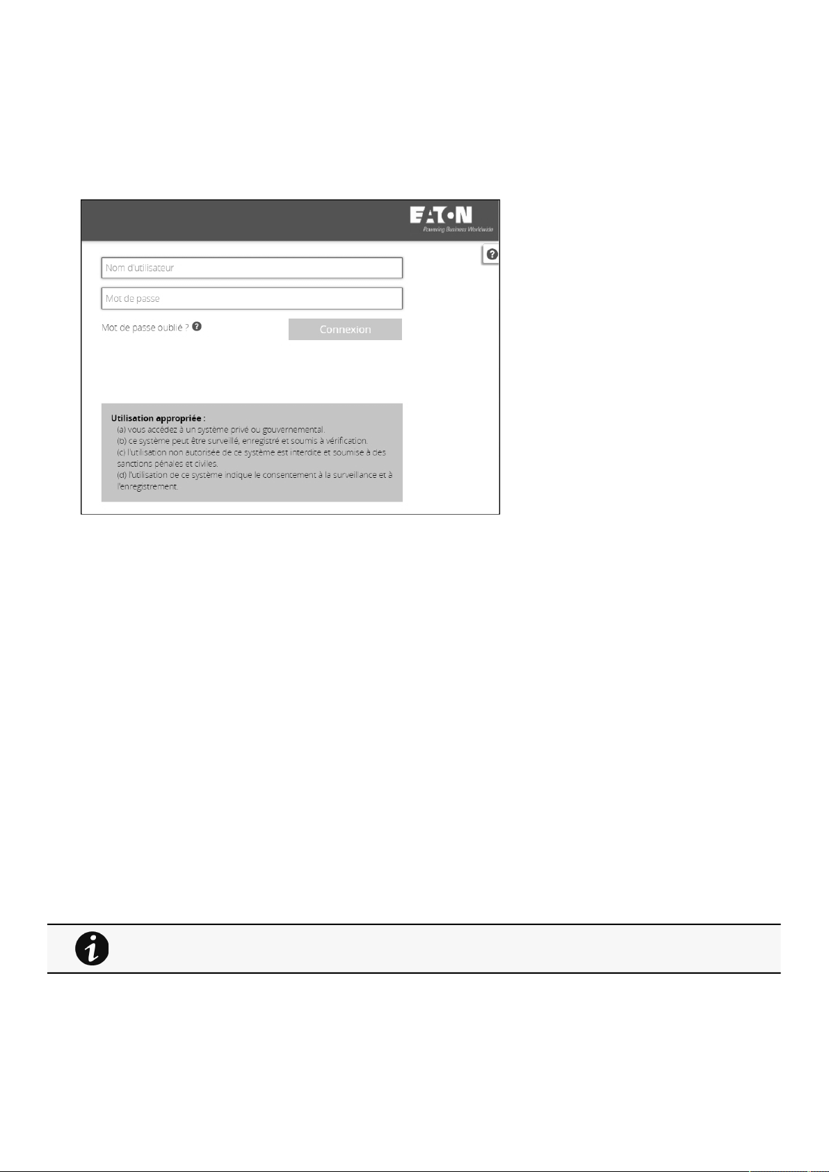
Login page
Contextual Help – 13
•
•
2 Contextual Help
2.1 Login page
The page language is set toEnglishby default but can be switched tobrowser language when it is managed.
After navigating to theassigned IP address, accept the untrusted certificate on the browser.
2.1.1 Logging in for the first time
1.Enter default password
As you are logging into the Network Module for the first time you must enter the factory set default username and password.
Username = admin
Password = admin
2. Change default password
Changing the default password is mandatory and requested in a dedicated window.
Enter your current password first, and then enter the new password twice.
Follow the password format recommendations on the tooltip in order to define a secure password.
3. Accept license agreement
On the next step, License Agreement is displayed.
Read and accept the agreement to continue.
2.1.2 Troubleshooting login issues
2.2 Home
The Home screen providesstatus informationfor the deviceincluding synoptic diagrams, key measures andactive alarms.
For details on troubleshooting, see the
Troubleshooting
section.

Home
Contextual Help – 14
•
•
•
•
•
•
•
•
•
•
•
•
•
•
•
•
•
•
•
•
•
•
•
•
•
•
•
•
•
•
•
2.2.1 Menu structure
ButtonDescription
Home
Overview and status ofUPS Module:
Synoptic
Active alarms
Outlet status
Settings
Module settings:
General
Date & Time
Users
Network
Protocols
SNMP
Modbus
Certificates
Email
My preferences
Alarms
List of alarms with date and time:
Details
Clear
Export
Meters
Power:
Frequency
Voltage
Current
Power
Battery:
Overview
Details
Test
Measure logs:
Configuration
Measure logs
Controls
Control of:
Entire UPS
Outlets
Protection
Scheduled shutdown
Agent list
Agent settings
Power outage policy
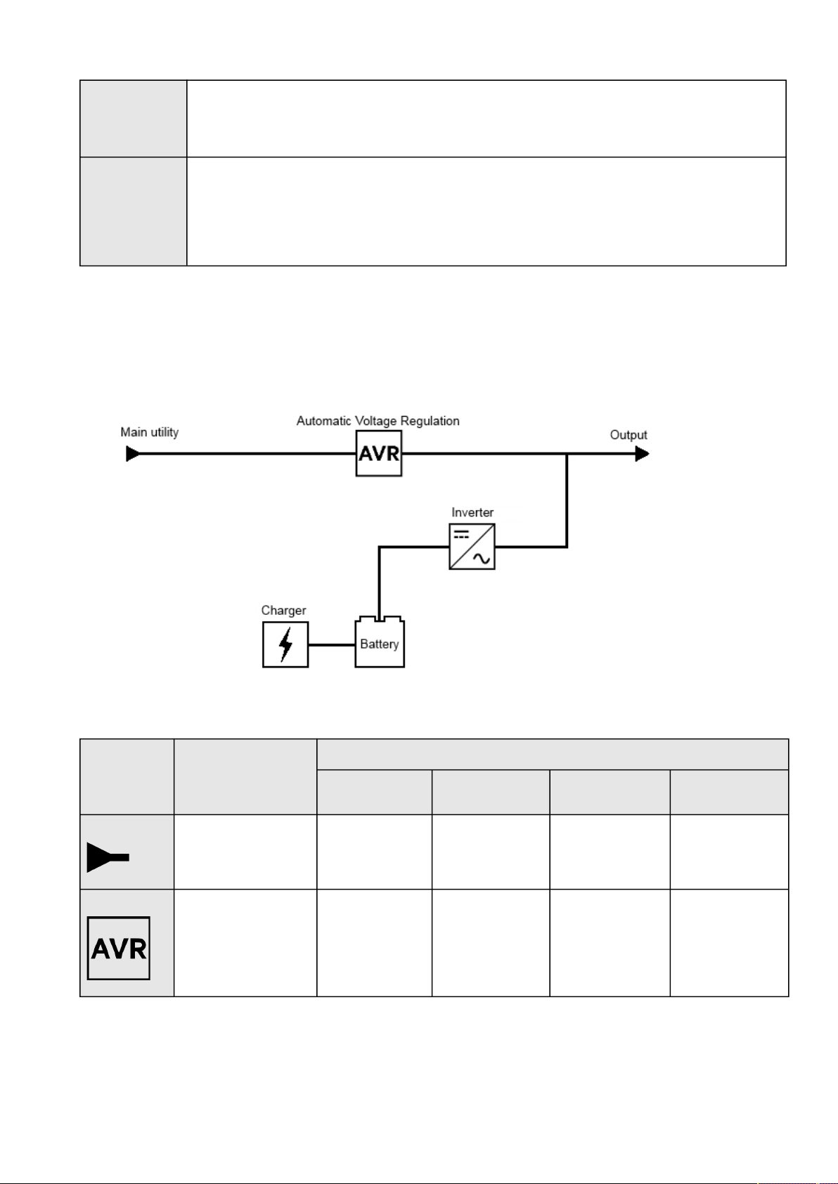
Home
Contextual Help – 15
•
•
•
•
•
•
•
Sensors*
Status
Alarm configuration
Information
Card
System information
System logs
Administration
Commissioning (Sensors)
*Displayed when sensors are commissioned in Card menu.
2.2.2 Energy flow diagram
2.2.2.1 Line interactive
2.2.2.1.1 Diagram elements description
Description and
symbols
DescriptionPossible states
GreenYellowRedBlack / White /
Greyed
InputMain utility input.PoweredOut of nominal rangeNot present
Unknown
AVR device.The equipment is
protected and powered
through an AVR device.
Normal mode
Buck mode
Boost mode
In overloadNot powered
Unknown
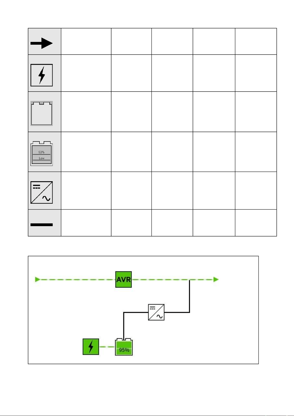
Home
Contextual Help – 16
OutputOutput of the UPS.ProtectedIn overload
Not protected
In short circuitNot powered
Unknown
ChargerInternal battery charger.Charging
Floating
In faultResting
Not powered
Unknown
Battery statusBattery status information.Powering the loadEnd of lifeIn fault
Not present
Not used to power
the load
Unknown
Battery levelBattery level for the
backup power.
> 50%
and
> low battery
threshold (Settable
on the UPS)
< 50%
and
> low battery
threshold (Settable
on the UPS)
< Below low battery
threshold (Settable on
the UPS)
InverterInverter: convert DC
power to AC power.
PoweredIn overloadIn short circuit
In fault
Not powered
Unknown
WiringElectrical connection
between blocks.
Energy flowIn overload
Out of nominal range
No energy
Unknown
2.2.2.1.2 Line interactive diagram examples
Normal mode
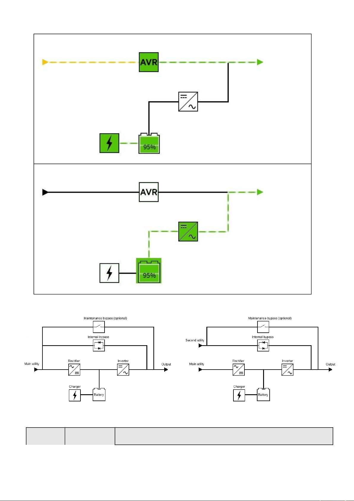
Home
Contextual Help – 17
Buck/Boost mode
Battery mode
2.2.2.2 Online
2.2.2.2.1 Diagram elements description
Description and
symbols
DescriptionPossible states
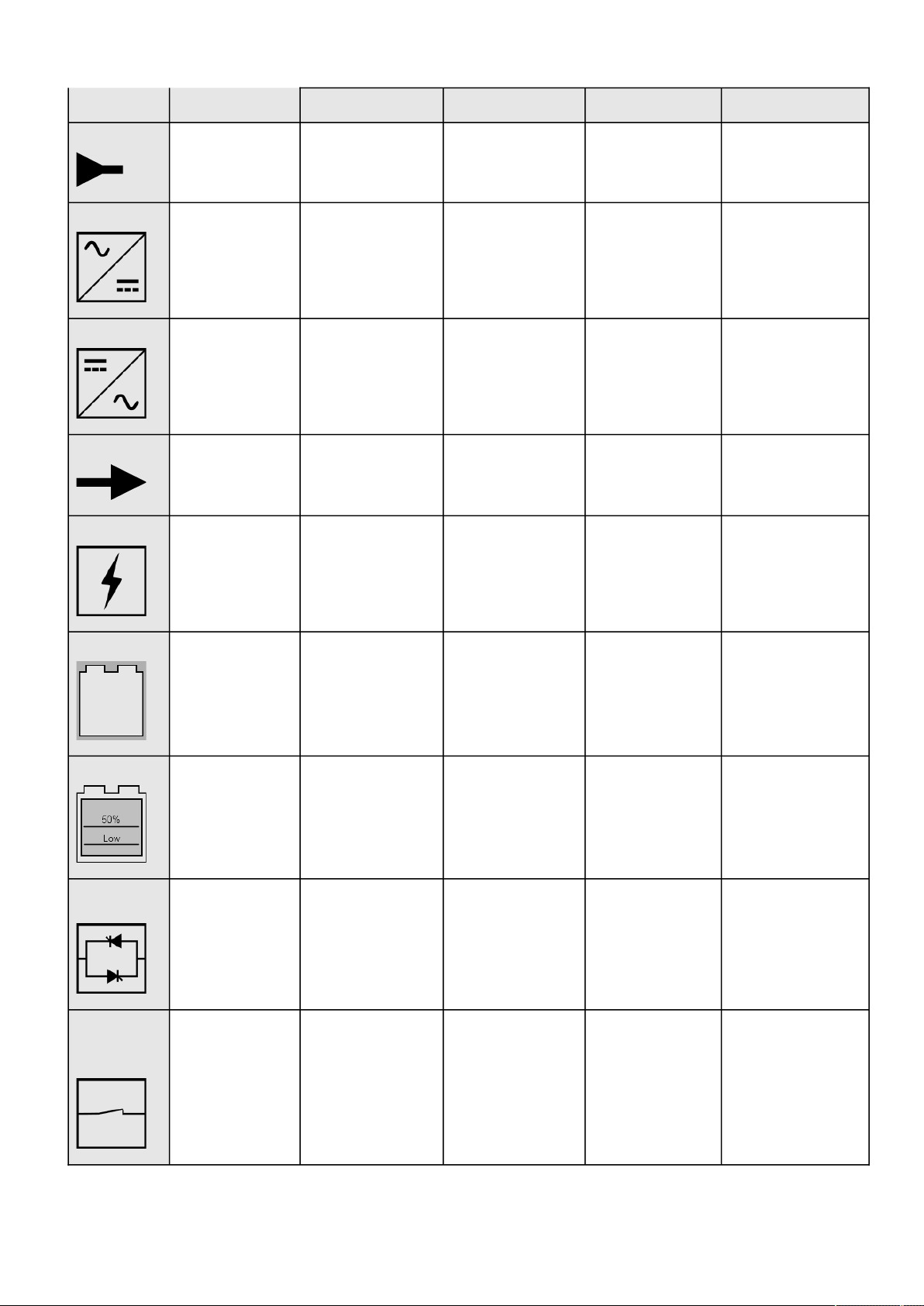
Home
Contextual Help – 18
GreenYellowRedBlack or white
InputMain utility or second
utility.
PoweredOut of nominal rangeNot present
Unknown
RectifierRectifier: convert AC
power to DC power.
Powered
HE mode (ready) / ESS
mode (ready)
In overloadIn short circuit
In fault
Not powered
Unknown
InverterInverter: convert DC
power to AC power.
Powered
HE mode (ready) / ESS
mode (ready)
In overloadIn short circuit
In fault
Not powered
Unknown
OutputOutput of the UPS.ProtectedIn overload
Not protected
In short circuitNot powered
Unknown
ChargerInternal battery
charger.
Charging
Floating
In faultResting
Not powered
Unknown
Battery statusBattery status
information.
Powering the loadEnd of lifeIn fault
Not present
Not used to power the
load
Unknown
Battery levelBattery level for the
backup power.
> 50% and > low
battery threshold
(Settable on the UPS)
< 50% and > low
battery threshold
(Settable on the UPS)
< Below low battery
threshold (Settable on
the UPS)
Automatic
bypass
Automatic bypass.Powered (standby, auto
bypass, forced bypass,
HE mode, ESS mode)
In overloadIn faultNot powered
Unknown
Maintenance
bypass
(optional)
Maintenance bypass
closed.
Powered (maintenance
bypass)
Not powered
Unknown
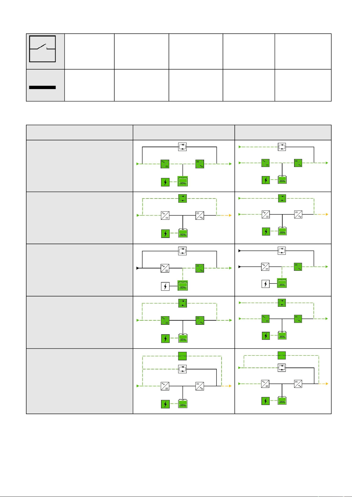
Home
Contextual Help – 19
Maintenance bypass
opened.
WiringElectrical connection
between blocks.
Energy flowIn overload
Out of nominal range
No energy
Unknown
2.2.2.2.2 Online diagram examples
Single input source
Dual input sources
Online mode
Bypass mode
Battery mode
HE mode / ESS mode
Maintenance bypass mode
2.2.3 Top bar
Card name– Displays the card name

Home
Contextual Help – 20
•
•
•
•
•
•
•
•
•
•
UPS name – Displays by default the UPS model or the system name if filled in the section Card>>>System
information>>>System name
Current user– Displays current user name
Logout–Logs the current user out by destroying the current user session
Status–Provides device (example UPS) status information
Output power– Provides output power status information
Battery status– Provides battery status information
Alarms button– Open alarm page
Settings button– Open settings page
2.2.4 Details
Thisview provides a summary of device identification information and nominal values:
Name
Model
P/N
S/N
Location
Firmware version
Input Voltage
Input Frequency
Output Voltage
Output Frequency
The
COPY TO CLIPBOARD button will copy the information toyour clipboard so that it can be past.
For example, you can copy and paste information into an email.
2.2.5 Show measures
Provides input and output measures on the synoptic.
2.2.5.1 Example #1
Single input source with 1 phase in and 1 phase out:
Input measuresOutput measures
Voltage (V)
Current (A)
Frequency (Hz)
Voltage (V)
Current (A)
Frequency (Hz)
2.2.5.2 Example #2
Dual input sources with 3 phases in and 3 phases out
Input measures (main and secondary)Output measures
Phase #1
Voltage (V)
Current (A)
Phase #2
Voltage (V)
Current (A)
Phase #3
Voltage (V)
Current (A)
Phase #1
Voltage (V)
Current (A)
Phase #2
Voltage (V)
Current (A)
Phase #3
Voltage (V)
Current (A)
Load (W)
Load (%)
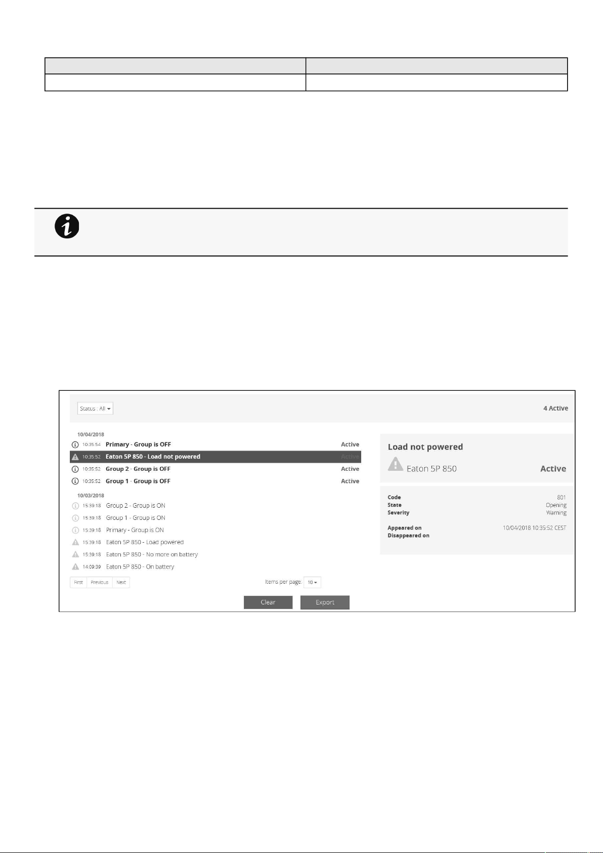
Alarms
Contextual Help – 21
•
•
•
•
•
•
Input measures (main and secondary)Output measures
Frequency (Hz)Frequency (Hz)
2.2.6 Outlet status
Providesthe status of the UPS outlets (ON/OFF) by load segmentation:
Status (ON/OFF— Protected/Not protected/Not powered)
Load level (W)– availability depending on the UPS model
Shutdown countdown
Startup countdown
2.2.7 Active Alarms
Only active alarms are displayed, the Alarmsicon will alsodisplay the number of active alarms.
Alarms are sorted by date,alert level, time, anddescription.
Note:To seethe alarm history,press the
Alarms button.
2.3 Alarms
2.3.1 Alarm sorting
Alarms can be sorted by selecting:
All
Active only
2.3.2 Alarm details
Allalarms are displayed andsorted by date, with alert level, time, description, and status.
Note: Load segmentations allow non-priority equipment to automatically power down during an
extended power outage to keep battery runtime on essential equipment.
This feature is also used toremote reboot and sequential startservers to restrict inrush currents.
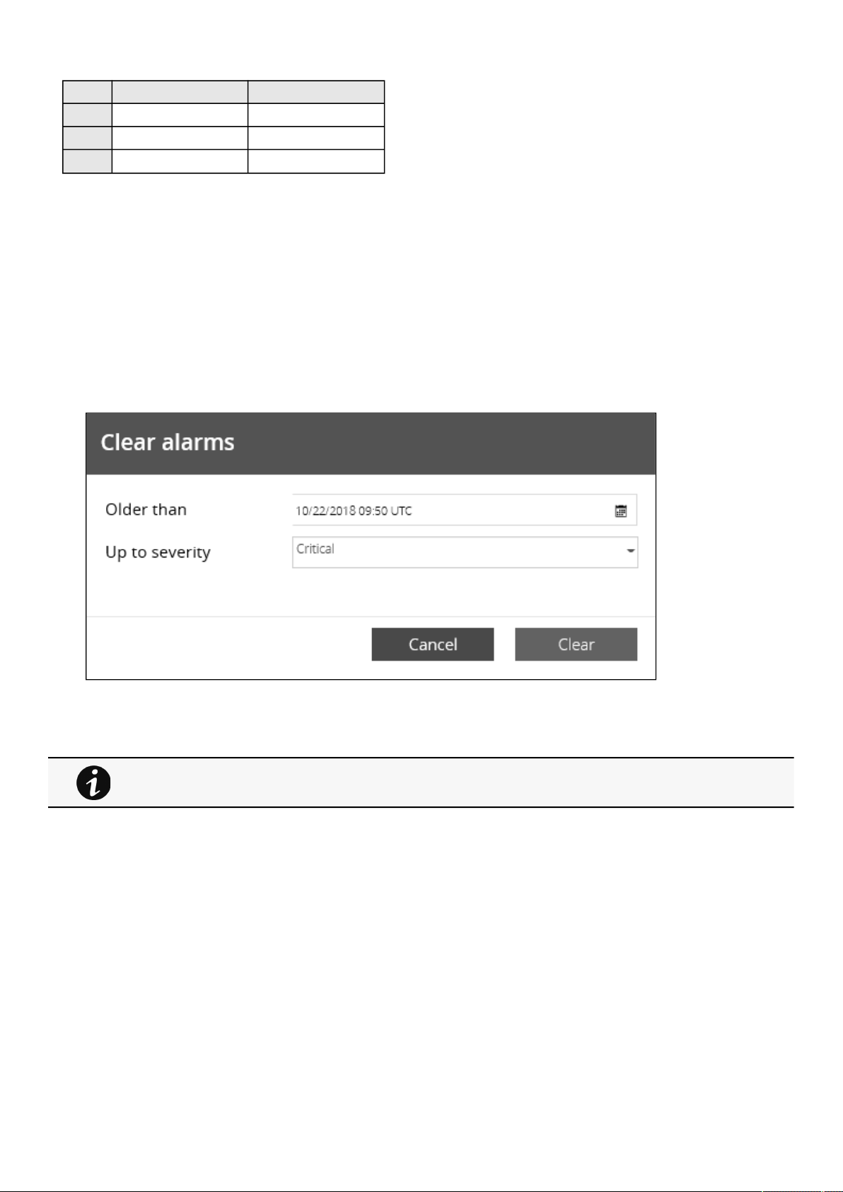
Alarms
Contextual Help – 22
Info/Warning/Critical logoAlarm description text
ActiveIn colorIn bold with "Active" label
OpenedIn color
ClosedGreyed
2.3.3 Alarm paging
The number of alarms per page can be changed (10-15-25-50-100).
When the number of alarms is above the number of alarms per page,the buttons
First, Previous andNextappears to allow
navigation in the Alarm list.
2.3.4 Alarm export
Press the
Exportbutton to download the file.
2.3.5 Clear alarm logs
Press theClearbutton to clear alarms that are older than a specified date and up to a defined severity.
2.3.6 Alarm list with codes
For details on alarm codes, see the
Information>>>Alarm log codes
section.
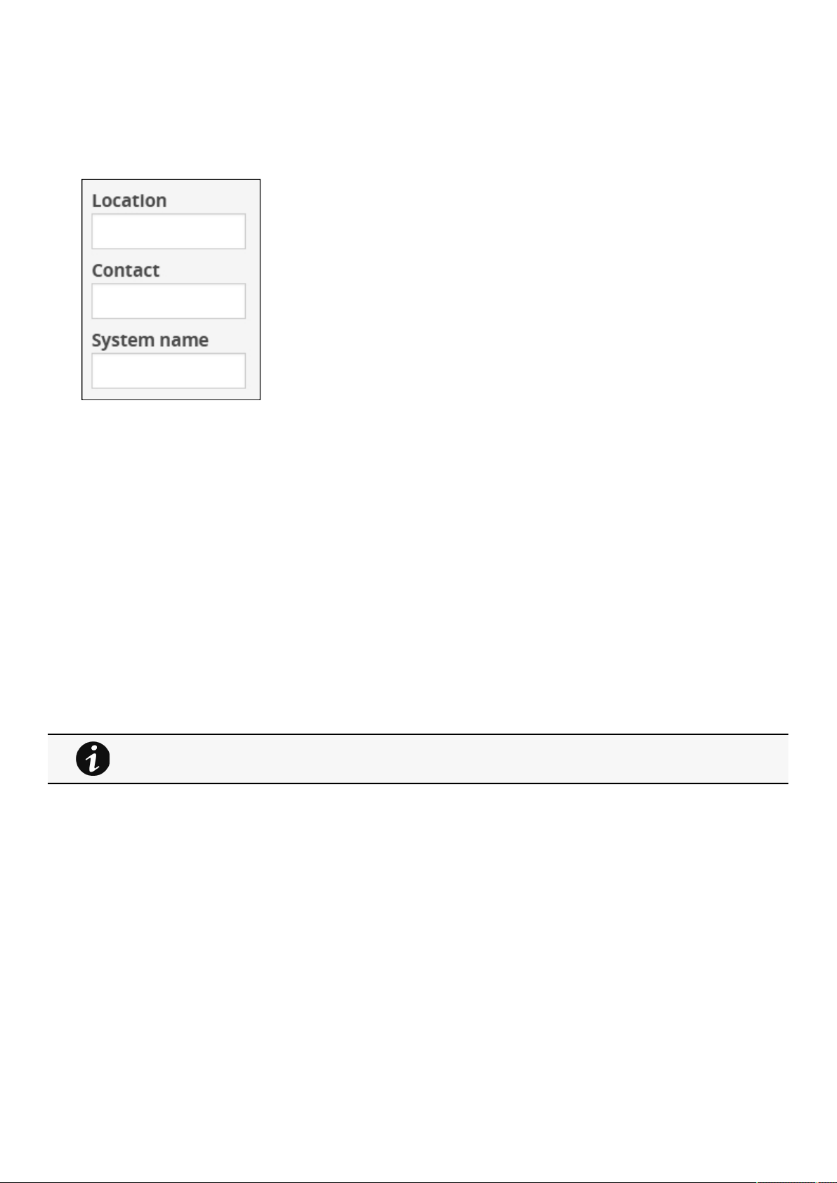
Settings
Contextual Help – 23
2.4 Settings
2.4.1 General
2.4.1.1 Location
Text field that is used to provide the card location information.
Card system information is updated to show the defined location.
2.4.1.2 Contact
Text field that is used to provide the contact name information.
Card system information is updated to show the contact name.
2.4.1.3 System name
Text field that is used to provide the system name information.
Card system information is updated to show the system name.
2.4.1.4 Default settings parameters and limitations
2.4.2 Date & Time
For details on default parameters and limitations, see the
Information>>>Default settings
parameters
section.
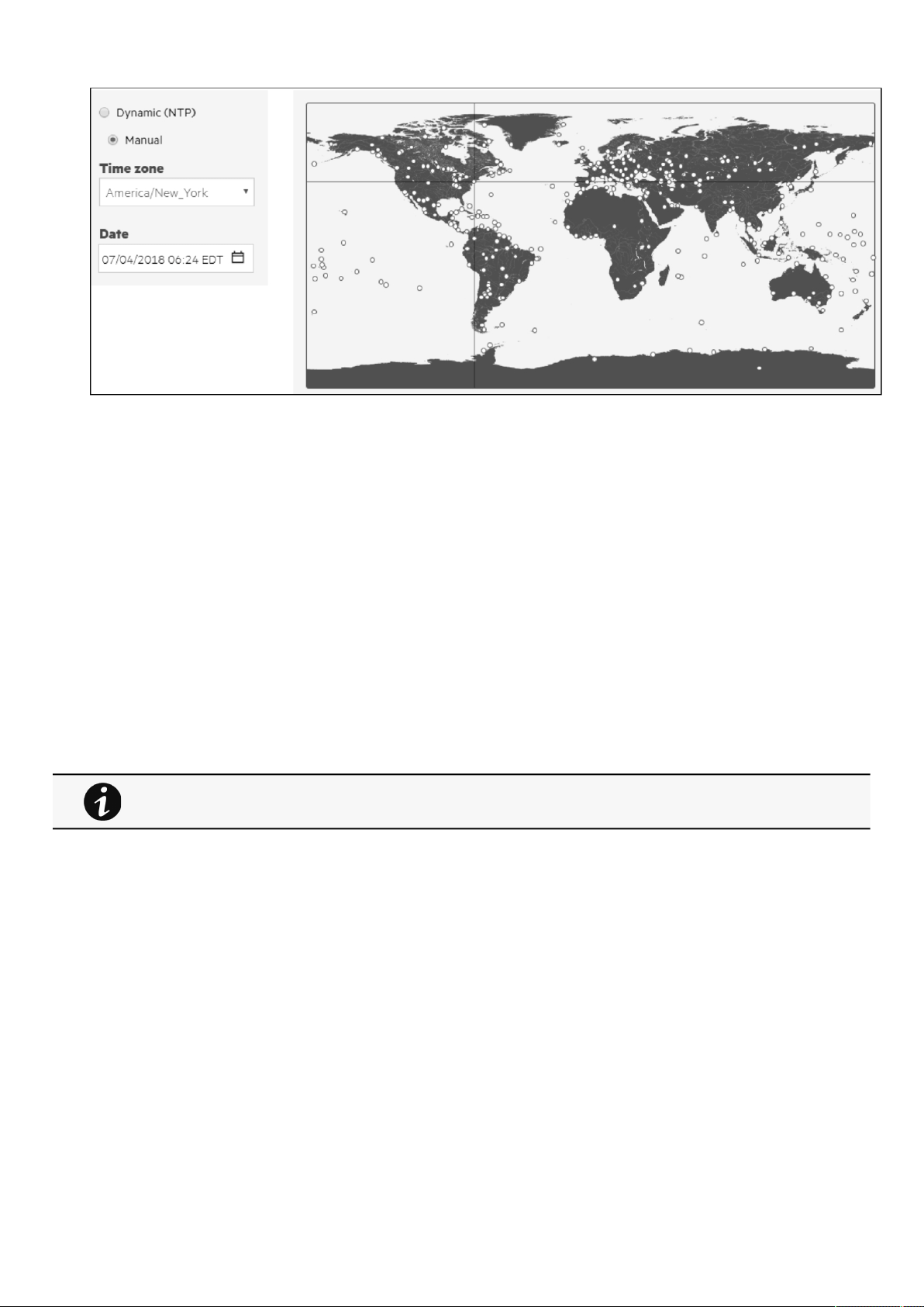
Settings
Contextual Help – 24
1.
2.
3.
1.
2.
3.
The current date and time appearsin the footer at the bottom of the screen.
You can set the time either manually or automatically.
2.4.2.1 Manual:Manually entering the date and time
Select the time zone for your geographic area from the time zone pull-down menu orwiththe map.
Select the date and time.
Save the changes.
2.4.2.2 Dynamic (NTP):Synchronizing the date and time with an NTP server
Enter the IP address or host name of the NTP server in theNTP server field.
Select the time zone for your geographic area from the time zone pull-down menu orwiththe map.
Save the changes.
Note:DST is managed based on the time zone.
2.4.2.3 Default settings parameters and limitations
For details on default parameters and limitations, see the
Information>>>Default settings
parameters
section.
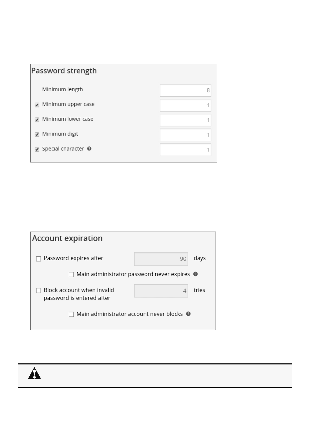
Settings
Contextual Help – 25
•
•
•
•
•
•
2.4.3 Users
2.4.3.1 Password strength rules
To set the password strength rules, apply the following restrictions:
Minimum length
Minimum upper case
Minimum lower case
Minimum digit
Special character
PressSaveafter modifications.
2.4.3.2 Account expiration
To set the account expiration rules, apply the following restrictions:
Password expires after (in days).
The main administrator password never expires.
1.
2.
If this feature is disabled, the administrator account can be locked after the password expiration.
If Enabled, the administrator password never expires, make sure it is changed regularly.
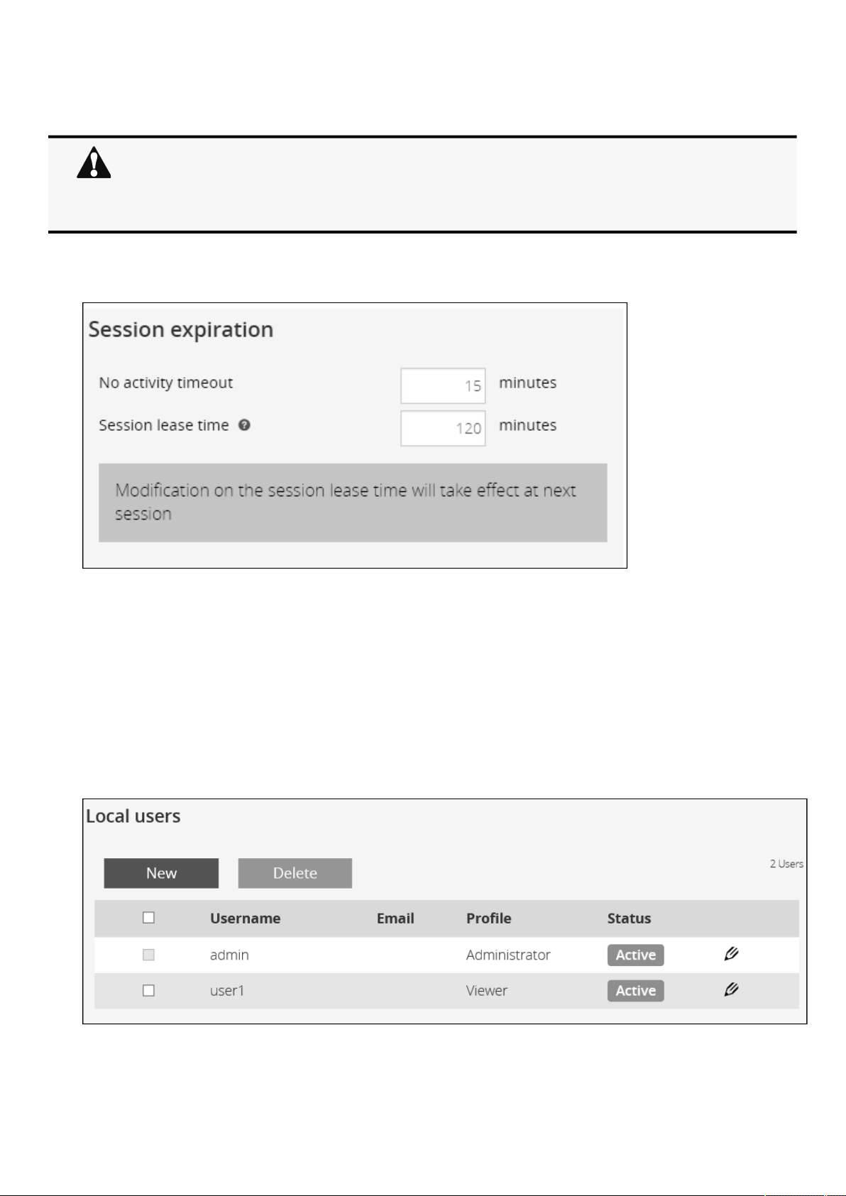
Settings
Contextual Help – 26
•
•
•
▪
Block account when invalid password is entered after (in number of attempts).
The main administrator account will never block.
PressSaveafter modifications.
2.4.3.3 Session expiration
To set the session expiration rules,apply the following restrictions:
No activity timeout (in minutes).
If there is no activity, session expires after the specified amount of time.
Session lease time (in minutes).
If there is activity, session still expires afterthe specified amount of time.
PressSaveafter modifications.
2.4.3.4 Local users table
The table shows all the supported local user accounts and includes the following details:
Username
1.
2.
If this feature is disabled, the administrator account can be locked after the number of failed connections
defined.
If Enabled, the security level of the administrator account is reduced because unlimited password entry
attempts are allowed.
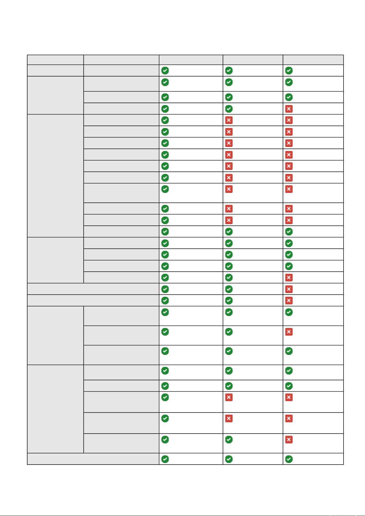
Settings
Contextual Help – 27
▪
▪
Email
Profile
AdministratorOperatorViewer
Home
AlarmsAlarm list
Export
Clear
SettingsGeneral
Date & Time
Users
Network
Protocols
SNMP
Modbus*
Certificates
Email
My preferences
MetersPower
Battery
Measure logs
Configuration
Controls
Protection
SensorsStatus
Alarm configuration
Information
CardSystem information
Resources
System logs
Administration
Commissioning (Sensors)
Legal information (footer)
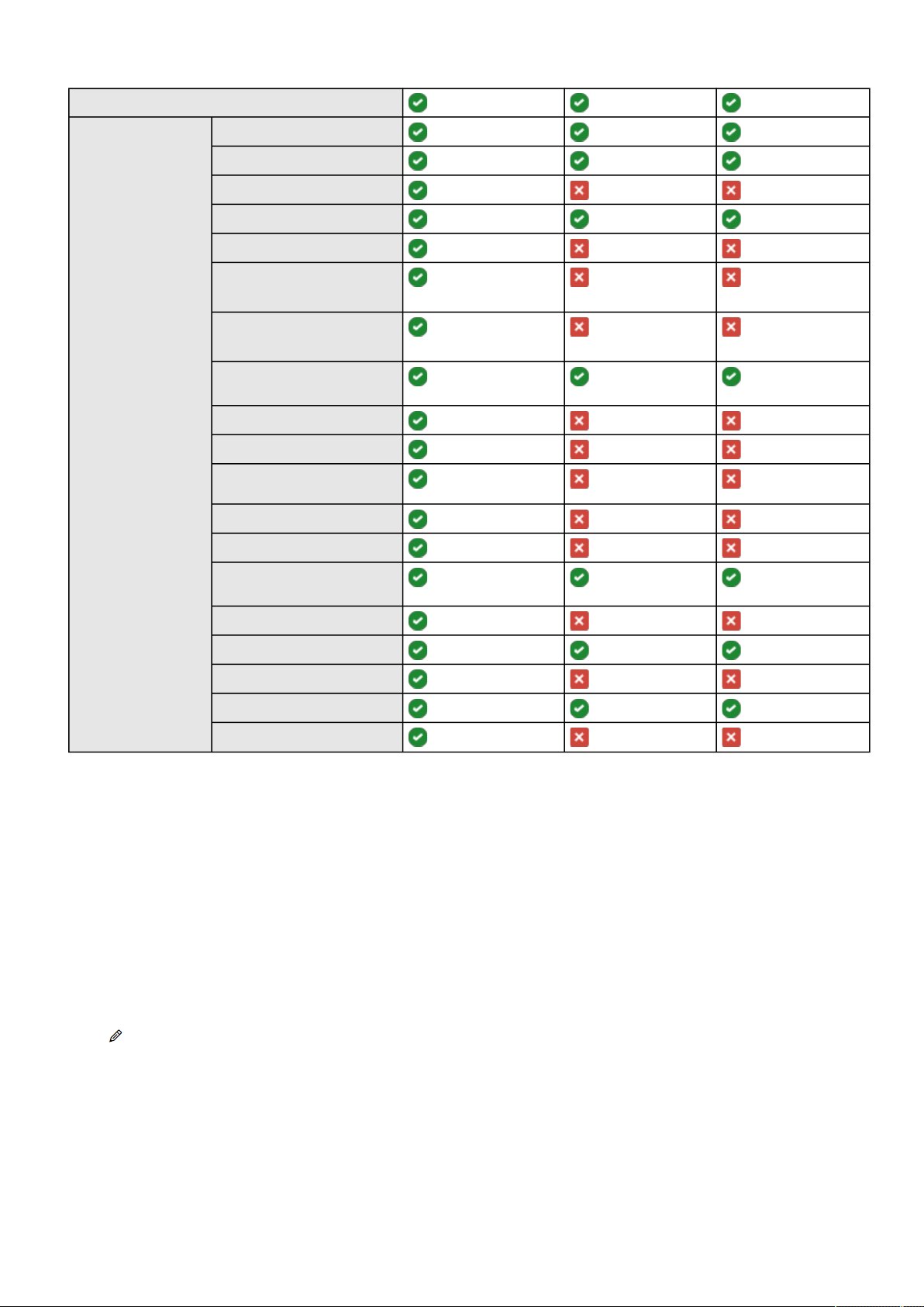
Settings
Contextual Help – 28
•
•
•
•
•
Contextual and Full documentation
Command Line
Interface
get release info
history
ldap-test
logout
maintenance
modbus_message_display*
modbus_statistics*
netconf (read-only)
(read-only)(read-only)
ping and ping6
reboot
save_configuration |
restore_configuration
sanitize
ssh-keygen
time
(read-only)(read-only)
traceroute and traceroute6
whoami
email-test
systeminfo_statistics
certificates
*for INDGW-M2 only
Status –Status could take following values– Inactive/Locked/Password expired/Active
2.4.3.4.1 Actions
a Add
Press the
New button to create up to ten new users.
b Remove
Select a user and press the
Delete button to remove it.
c Edit
Press the pen logo to edit user information and access to the following settings:
Active
Profile
Username
Full name
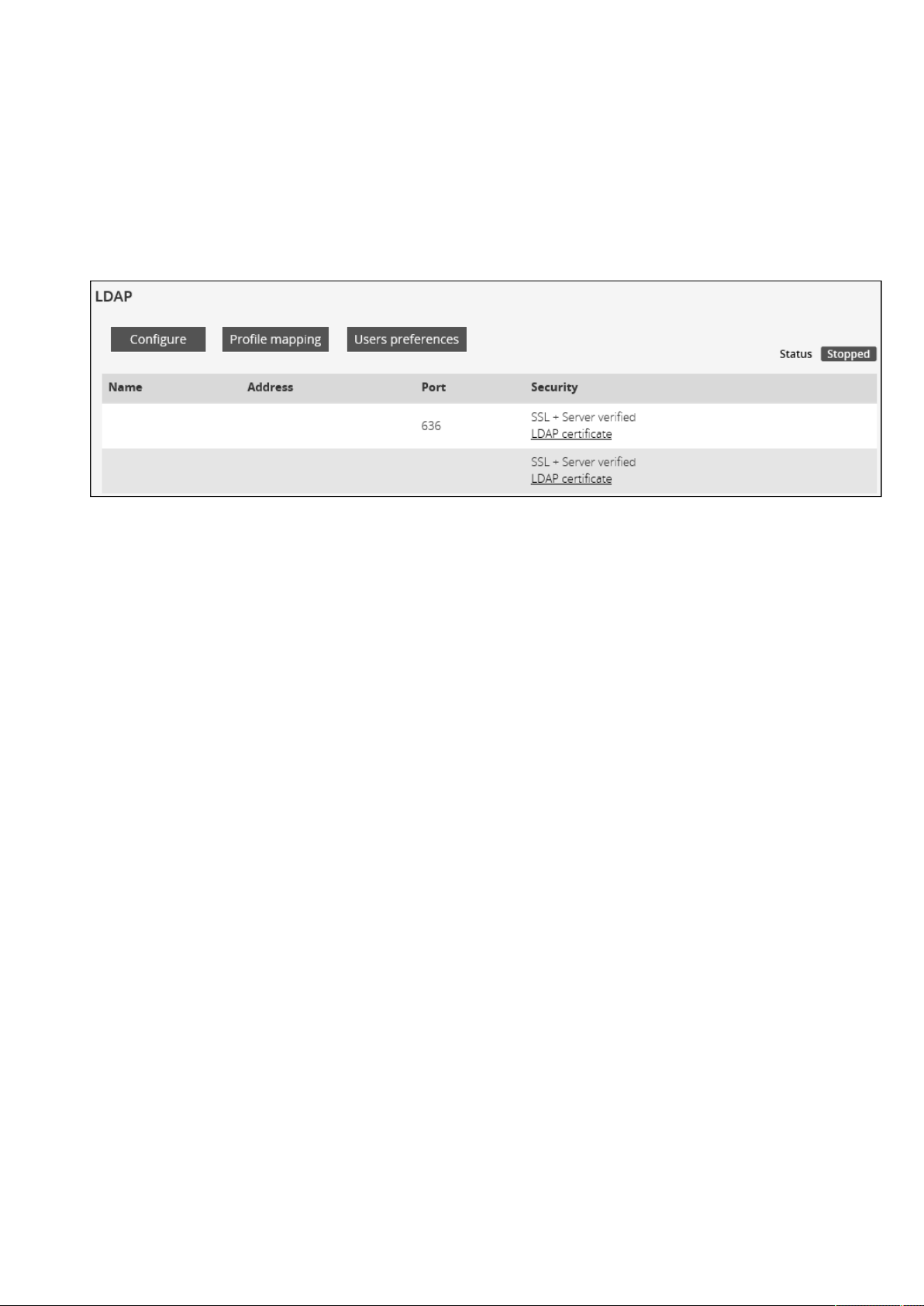
Settings
Contextual Help – 29
•
•
•
•
•
•
•
•
•
•
•
•
Email
Phone
Organization– Notify by email about account modification/Password
Reset password
Generate randomly
Enter manually
Force password to be changed on next login
2.4.3.5 LDAP
The table shows all the supported severs and includes the following details:
Name
Address
Port
Security
Status–Status could take following values– Unreachable/Active
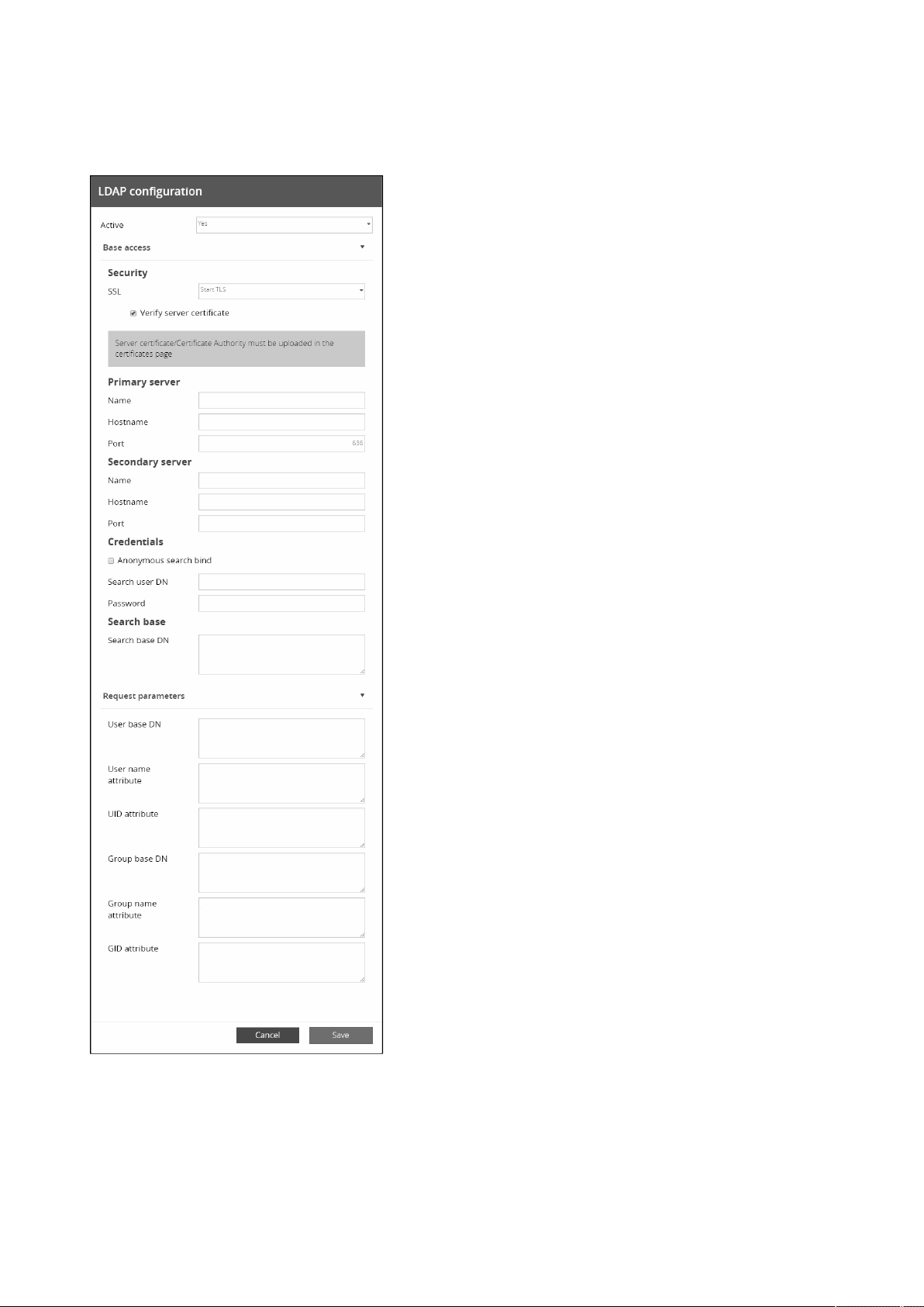
Settings
Contextual Help – 30
•
•
2.4.3.5.1 Actions
a Configure
1. Press Configureto access the following LDAP settings:
Active
Base access
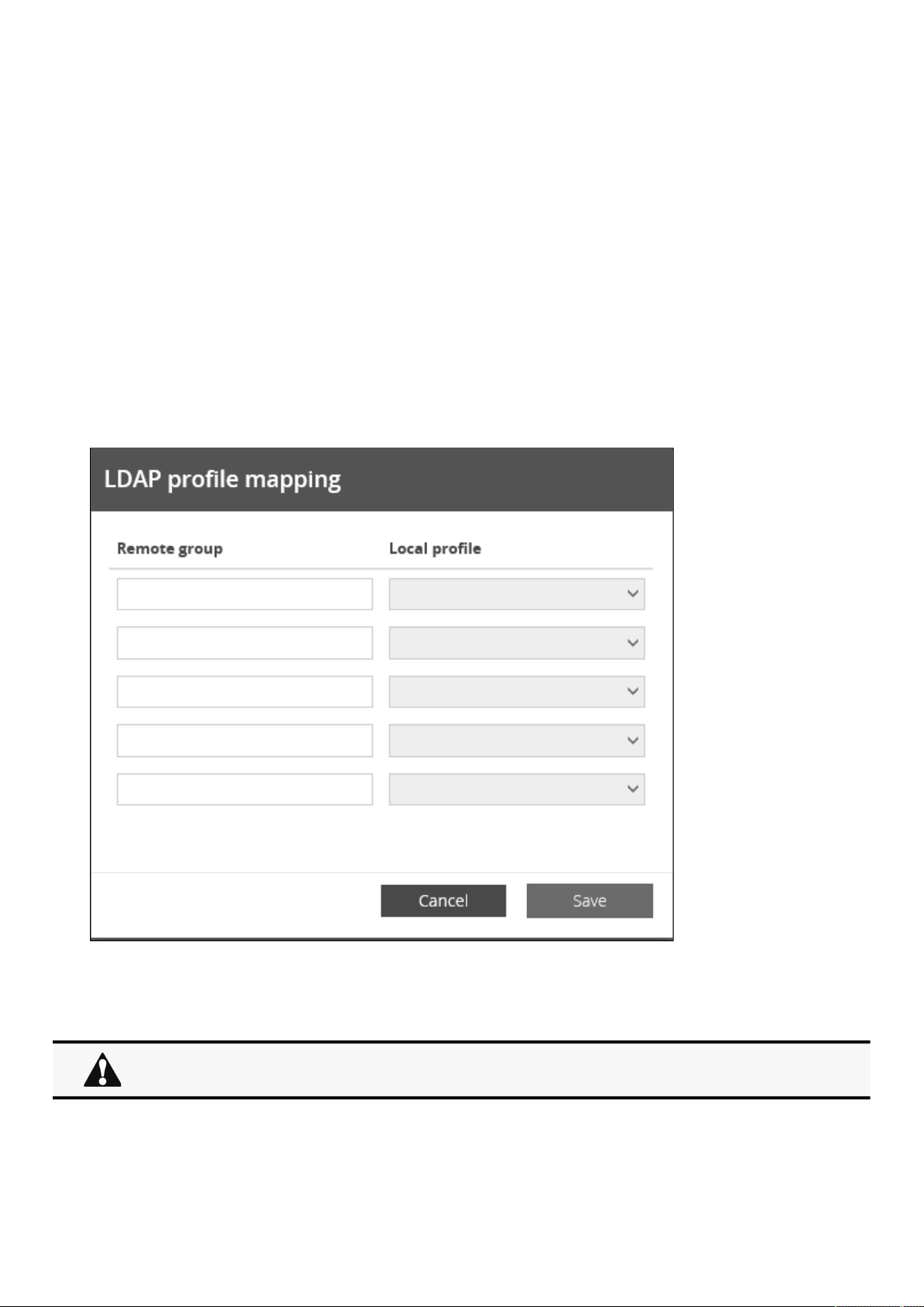
Settings
Contextual Help – 31
•
•
•
•
•
•
•
•
•
•
•
•
Security
SSL – None/Start TLS/SSL
Verify server certificate
Primary server–Name/Hostname/Port
Secondary server–Name/Hostname/Port
Credentials– Anonymous search bind/Search user DN/Password
Search base– Search base DN
Request parameters
User base DN
User name attribute
UID attribute
Group base DN
Group name attribute
GID attribute
2. Click Save.
b Profile mapping
1. Press Profile mapping to map remote groups to local profiles.
2. ClickSave.
c Users preferences
All users preferences will apply to all remote users (LDAP, RADIUS).
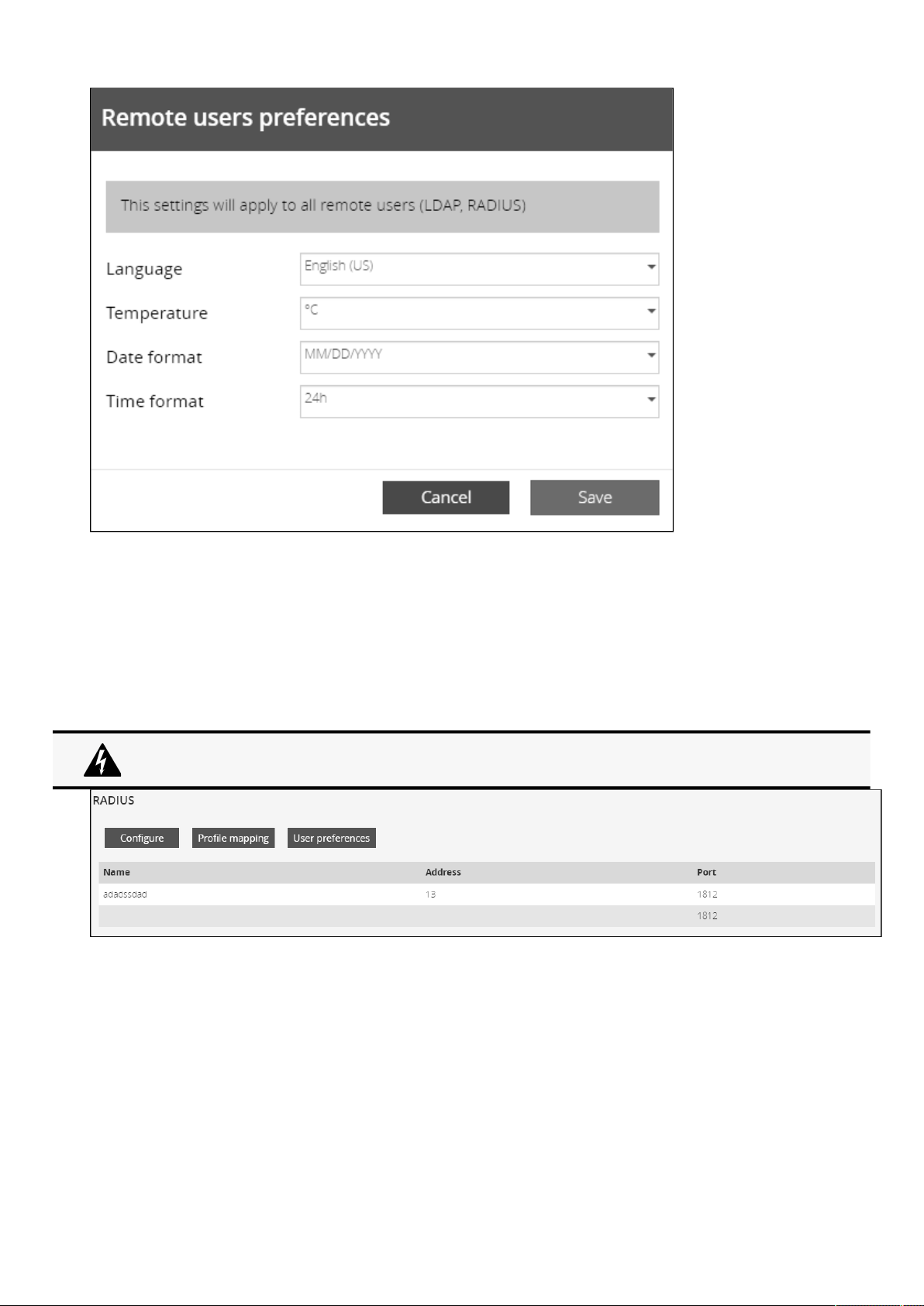
Settings
Contextual Help – 32
•
•
•
•
•
•
1. PressUsers preferencesto define preferences that will apply to all LDAP users
Language
Temperature
Date format
Time format
2. ClickSave.
2.4.3.6 RADIUS
The table shows all the supported severs and includes the following details:
Name
Address
Radius is not a secured protocol, for a maximum security, it is recomended to use LDAP over TLS.
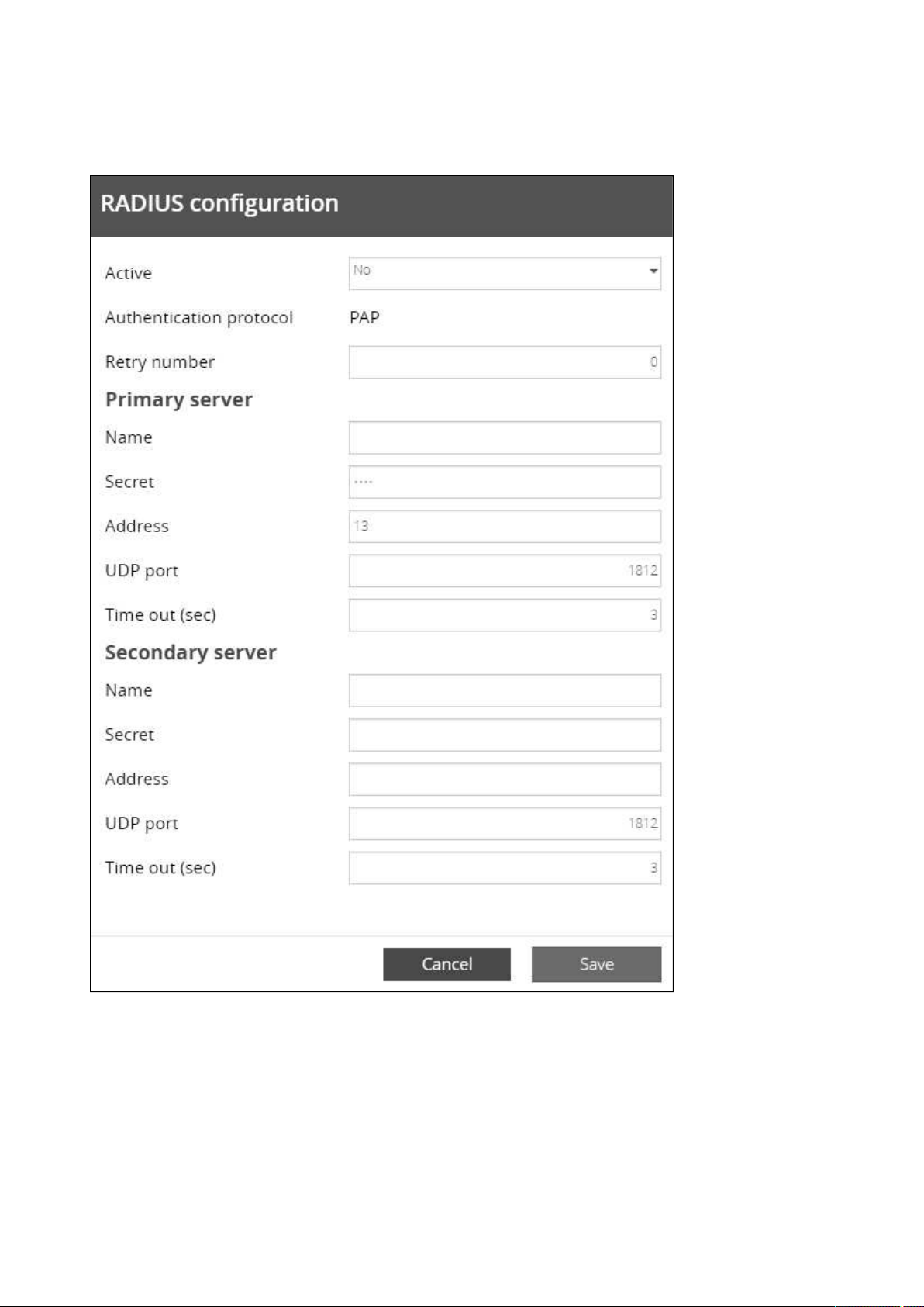
Settings
Contextual Help – 33
•
•
•
•
2.4.3.6.1 Actions
a Configure
1. PressConfigureto access the following RADIUS settings:
Active
Retry number
Primary server–Name/Secret/Address//UDP port/Time out (s)
Secondary server–Name/Secret/Address/UDP port/Time out (s)
2. ClickSave.
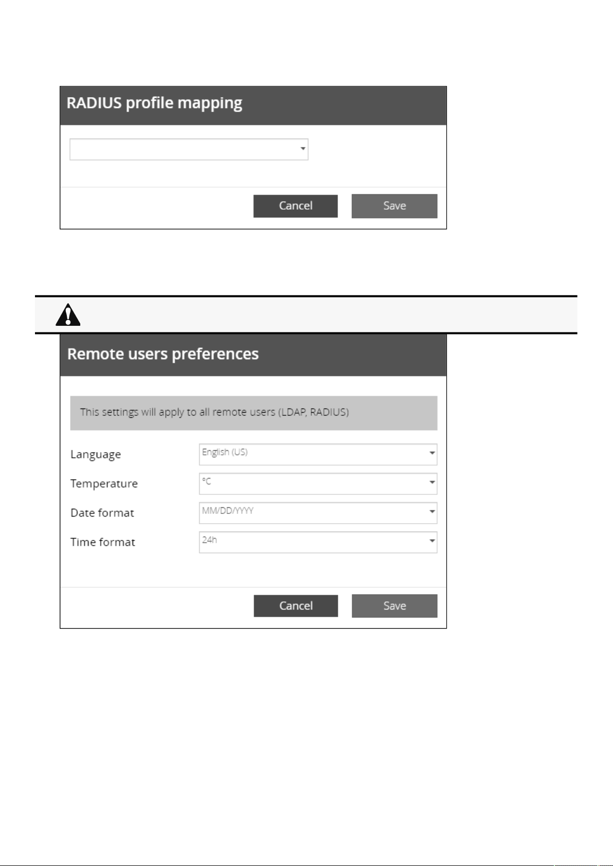
Settings
Contextual Help – 34
•
•
•
•
b Profile mapping
1. PressProfile mappingto map RADIUS profile to local profiles.
2. ClickSave.
c Users preferences
1. PressUsers preferencesto define preferences that will apply to all LDAP users
Language
Temperature
Date format
Time format
2. ClickSave.
All users preferences will apply to all remote users (LDAP, RADIUS).
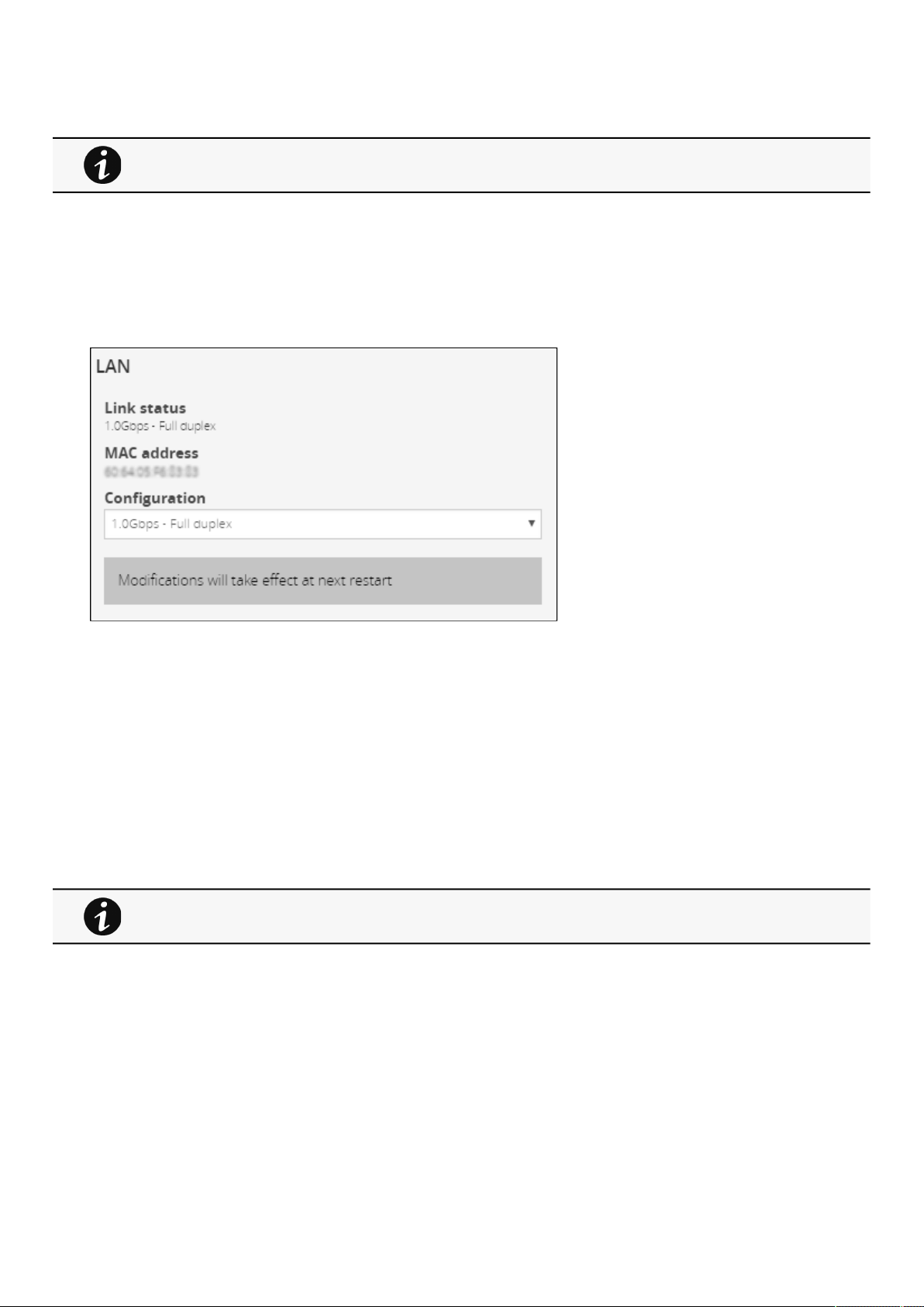
Settings
Contextual Help – 35
•
•
•
•
•
•
2.4.3.7 Default settings parameters and limitations
2.4.4 Network
2.4.4.1 LAN
A LAN is a computer network that interconnects computers within a limited area.
The available values for LAN configuration are listed below:
Auto negotiation
10Mbps -Half duplex
10Mbps -Full duplex
100Mbps - Half duplex
100Mbps -Full duplex
1.0 Gbps - Full duplex
Any modifications are applied after the nextNetwork Modulereboot.
2.4.4.2 IPv4
For details on default parameters and limitations, see the
Information>>>Default settings
parameters
section.
Any modifications are applied after the Network Module reboots.
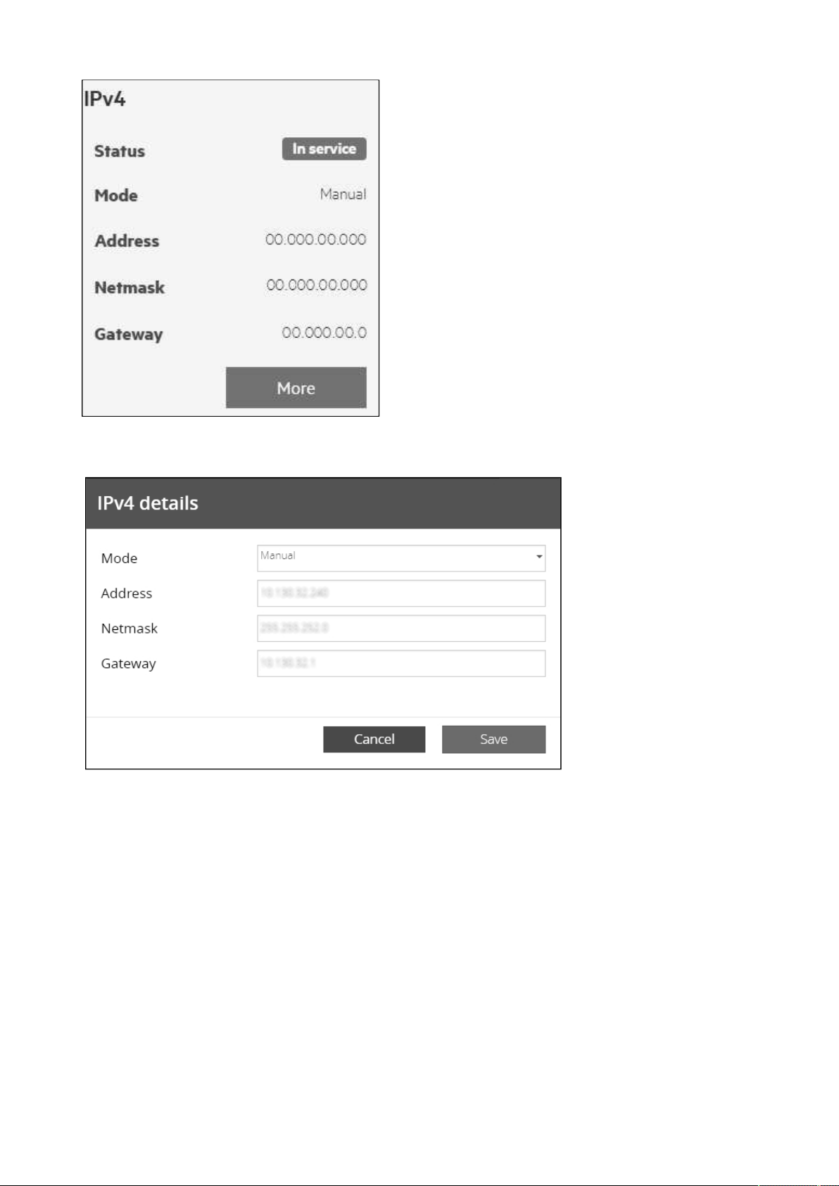
Settings
Contextual Help – 36
•
•
•
Press theMorebutton to configure the network settings, select either the Manual or Dynamic settings option:
2.4.4.2.1 Manual
Select Manual, and then enter the network settings if the network is not configured with a BootP or DHCP server.
Enter the IP Address.
The Network Modulemust have a unique IP address for use on a TCP/IP network.
Enter the netmask.
The netmask identifies the class of the sub-network the Network Module is connected to.
Enter the gateway address.
The gateway address allows connections to devices or hosts attached to different network segments.
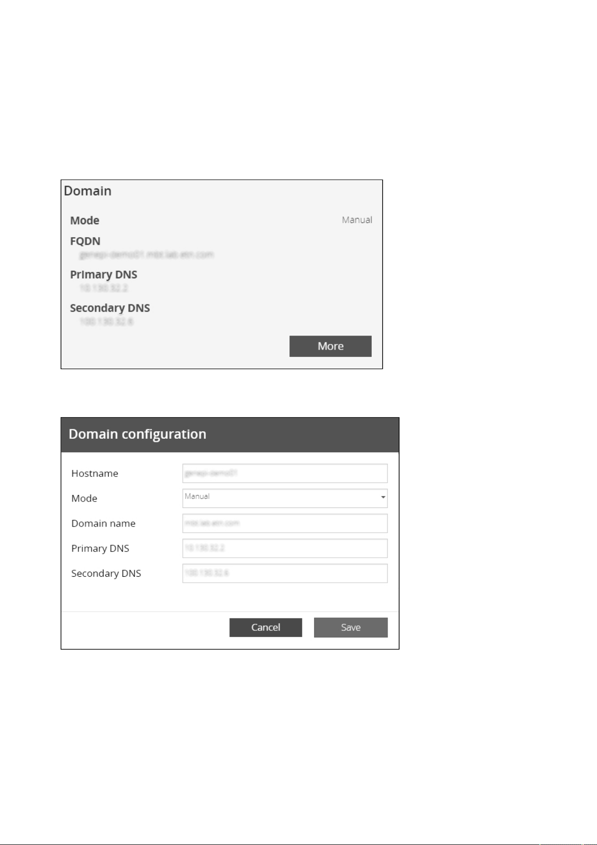
Settings
Contextual Help – 37
•
•
2.4.4.2.2 Dynamic (DHCP)
Select dynamic DHCP to configure network parameters by a BootP or DHCP server.
If a response is not received from the server, the UPS Network Module boots with the last saved parameters from the most recent
power up. After each power up, the UPS Network Module makes five attempts to recover the network parameters.
2.4.4.3 Domain
The DNS is a hierarchical decentralized naming system for computers, services, or other resources connected to the Internet or a
private network.
Press theMorebutton toconfigure the network settings, select either the Static or Dynamic settings.
2.4.4.3.1 Static
Enter the Network Module Hostname.
Enter the Network Module Domain name.
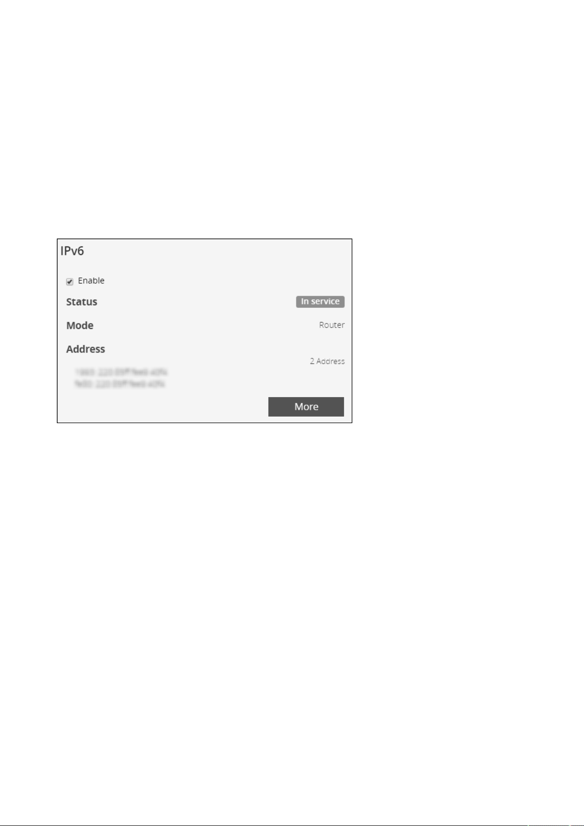
Settings
Contextual Help – 38
•
•
•
Primary DNS server.
Enter the IP address of the DNS server that provides the translation of the domain name to the IP address.
Secondary DNS server.
Enter the IP address of the secondary DNS server that provides the translation of the domain name to the IP address
when the primary DNS server is not available.
2.4.4.3.2 Dynamic
Enter the Network Module Hostname.
2.4.4.4 IPv6
IPV6 status and the first three addresses are displayed.
Press theMorebutton toconfigure the network settings and get more information, press the Morebutton for access to the
following IPV6 details.
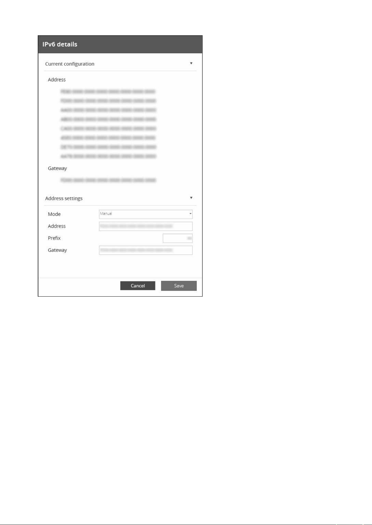
Settings
Contextual Help – 39
•
•
•
•
•
2.4.4.4.1 Current configuration
Address
Gateway
2.4.4.4.2 Address settings
Mode Manual
Addresses
Prefix
Gateway
Mode router
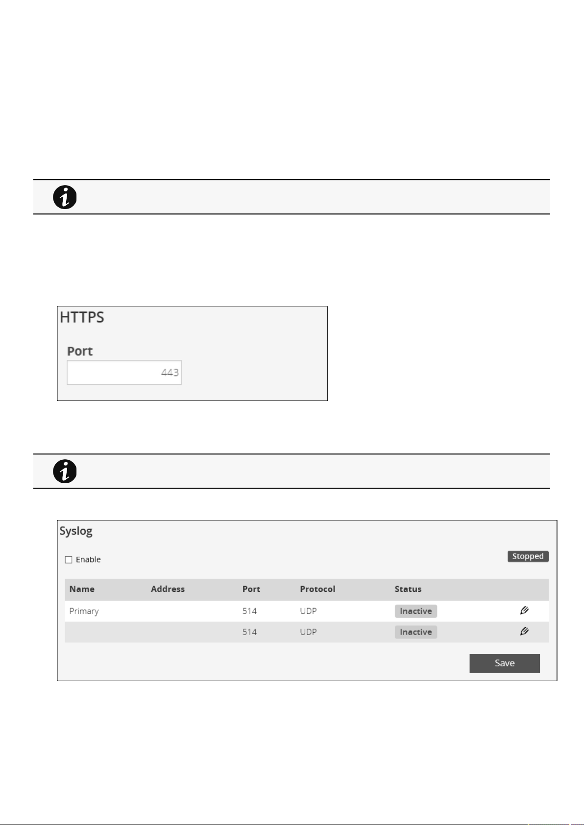
Settings
Contextual Help – 40
•
•
•
2.4.4.4.3 DNS settings
Get automatically (will hide the following settings)
Primary DNS
Secondary DNS
2.4.4.5 Default settings parameters and limitations
2.4.5 Protocols
This tab contains settings for communication protocols used to get information from the devicethrough the network, such as https
for web browser.
2.4.5.1 HTTPS
Only https is available.
The default network port for https is 443. For additional security, the ports can be changed on this page.
PressSaveafter modifications.
2.4.5.2 Syslog
2.4.5.2.1 Settings
This screen allows an administrator to configure up to two syslog servers.
For details on default parameters and limitations, see the
Information>>>Default settings
parameters
section.
Since only https is available, port 80 is not supported.
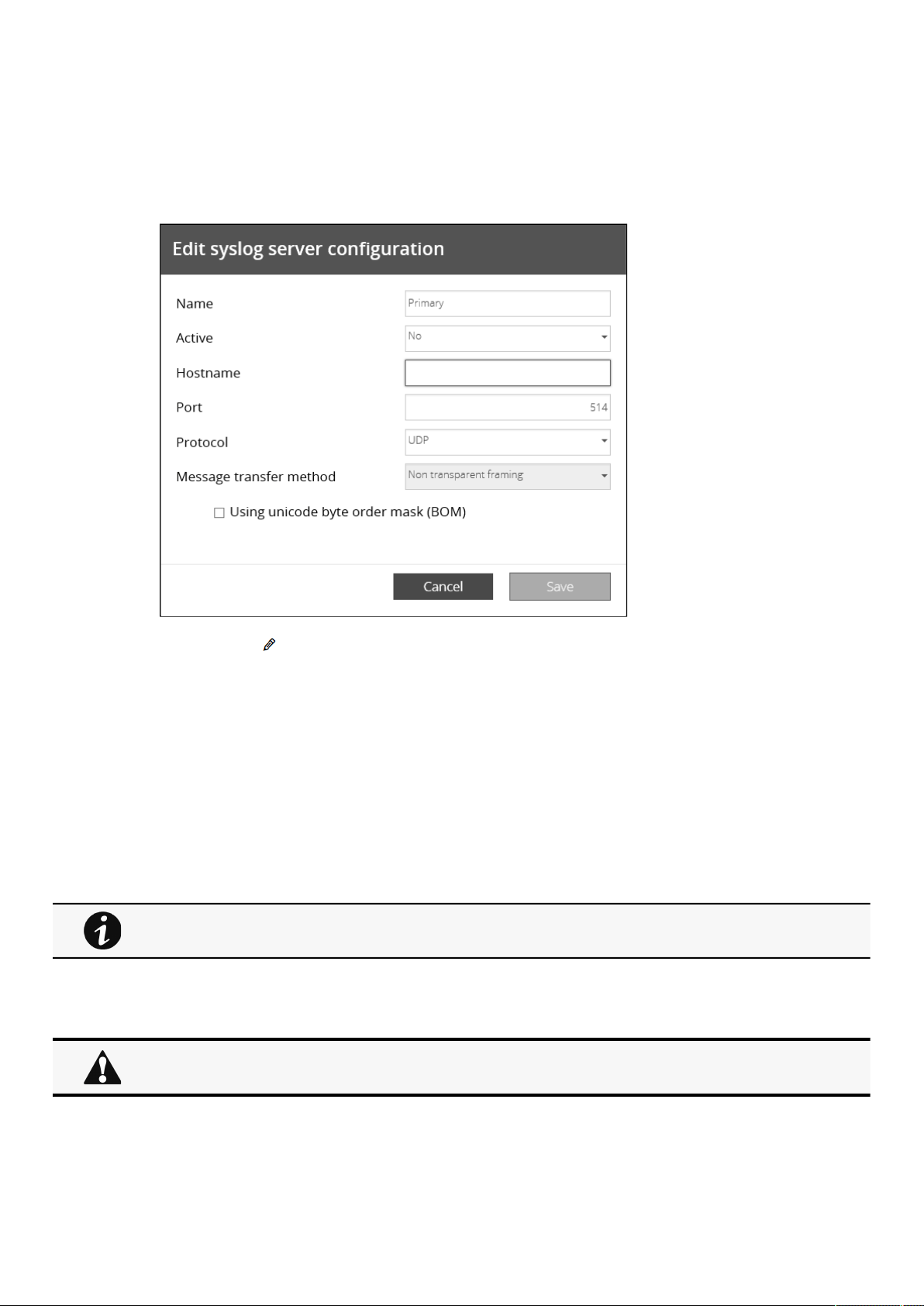
Settings
Contextual Help – 41
To configure the syslog server settings:
a 1- Enable syslog.
Press
Saveafter modifications.
b 2- Configure the syslog server:
1.Click the edit iconto access settings.
2. Enter or change the server name.
3. SelectYesin the Active drop-down list to activate the server.
4. Enter the Hostname and Port.
5. Select the Protocol – UDP/TCP.
6. In TCP, select the message transfer method – Octet counting/Non-transparent framing.
7. Select the option Using Unicode BOM if needed.
8.PressSaveafter modifications.
2.4.5.3 Default settings parameters and limitations
2.4.6 SNMP
This tab contains settings for SNMP protocols used for network management systems.
For details on default parameters and limitations, see the
Information>>>Default settings
parameters
section.
Changes to authentication settings need to be confirmed by entering a valid password for the active
user account.
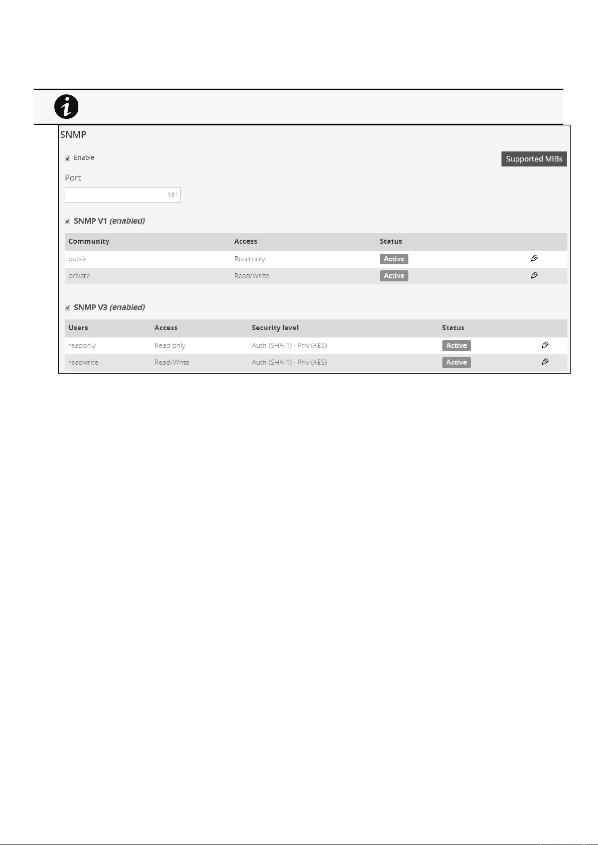
Settings
Contextual Help – 42
•
•
•
2.4.6.1 SNMP tables
SNMP monitoring Battery status, power status, events, and traps are monitored using third-party SNMP managers.
To query SNMP data, you do not need to add SNMP Managers to the Notified Application page.
To set-up SNMP managers:
Configure the IP address.
Select SNMP V1 or V1 and V3.
Compile the MIB you selected to be monitored by the SNMP manager.
For a list of supported MIBs, see the
Information>>>Specifications/Technical characteristics
section
.
Press theSupported MIBsbutton to download the MIBs.
2.4.6.1.1 Settings
This screen allows an administrator to configure SNMP settings for computers that use the MIB to request information from the
UPS Network Module.
Default ports for SNMP are 161 (SNMP v1 and v3, set/get) and 162 (traps). These ports can be changed on the settings screenfor
additional security.
To configure the SNMP settings:
a 1- Enable theSNMP agent.
In addition to this also v1 and/or v3 must be enabled, along with appropriate communities and activated user accounts to
allow SNMP communication.
Press
Saveafter modifications.
The default port for SNMP is 161 and normally this should not be changed. Some organizations prefer to
use non-standard ports due to cybersecurity, and this field allows that.
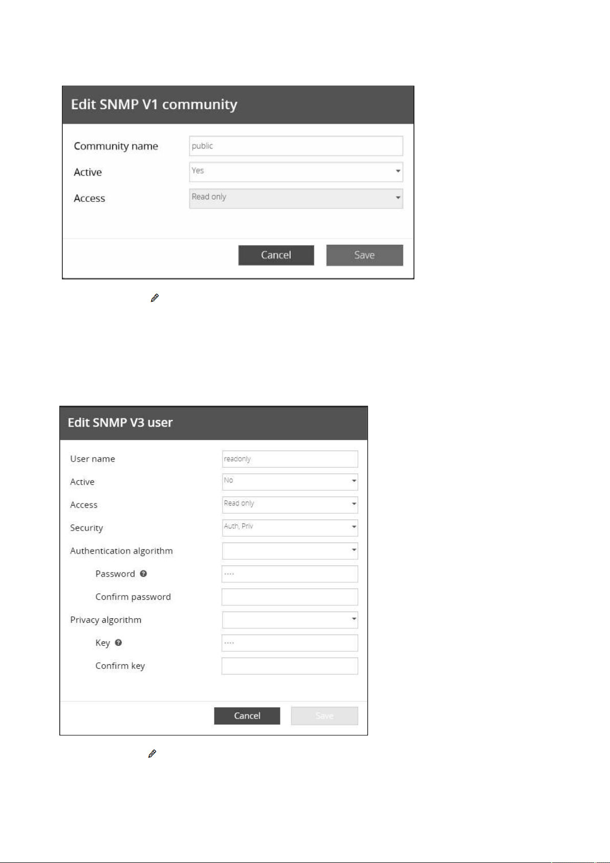
Settings
Contextual Help – 43
b 2- Configure the SNMP V1 settings:
1.Click the edit iconon either Read-only or Read/Write account to access settings.
2. Enter the SNMP Community Read-Only string. The UPS Network Module and the clients must share the same community
name to communicate.
3. Select
Yesin the Active drop-down list to activate the account.
4. Access level is set to display information only.
c 3- Configure the SNMP V3 settings:
1.Click the edit iconon either Read Only or Read/Write account to access settings.
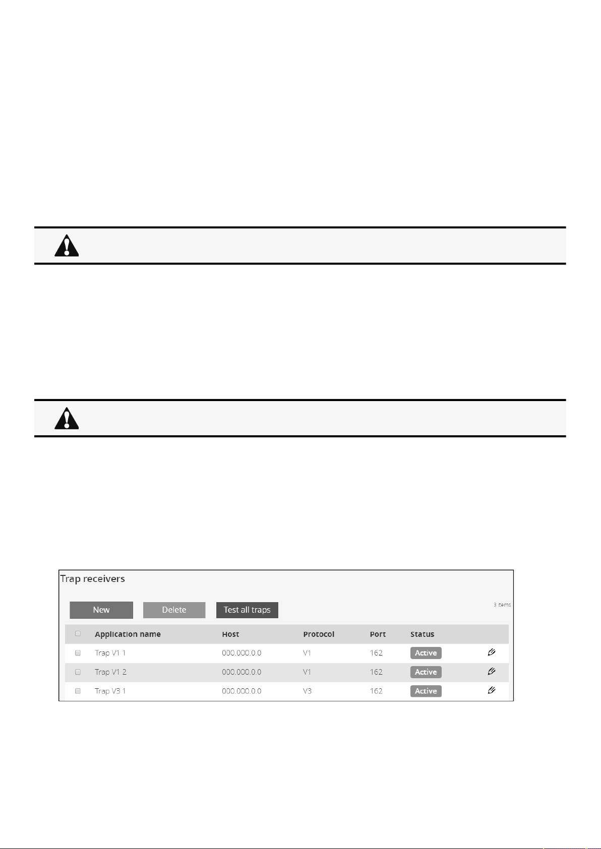
Settings
Contextual Help – 44
•
•
2. Edit the user name.
3. Select Yesin the Active drop-down list to activate the account.
4. Select access level.
Read only—The user does not use authentication and privacy to access SNMP variables.
Read/Write—The user must use authentication, but not privacy, to access SNMP variables.
5. Select the communication security mechanism.
Auth, Priv—Communication with authentication and privacy.
Auth, No Priv—Communication with authentication and without privacy.
No Auth, No Priv—Communication without authentication and privacy.
6. If Auth is selected on the communication security mechanism, select the Authentication algorithms.
SHA— SHA1 is not recommended as it is not secured.
SHA256—fill in password and privacy keys. The password can be between 8 and 24 characters and use a combination
of alphanumeric and the following special characters<>&@#%_=:;,./?|$*.
SHA384—fill in password and privacy keys. The password can be between 8 and 24 characters and use a combination
of alphanumeric and the following special characters<>&@#%_=:;,./?|$*.
SHA512—fill in password and privacy keys. The password can be between 8 and 24 characters and use a combination
of alphanumeric and the following special characters<>&@#%_=:;,./?|$*.
AES / AES192 / AES256
7. If Priv is selected on the communication security mechanism, select the Privacy algorithms.
AES— fill in password and privacy keys. The password can be between 8 and 24 characters and use a combination of
alphanumeric and the following special characters<>&@#%_=:;,./?|$*.
AES192—fill in password and privacy keys. The password can be between 8 and 24 characters and use a combination of
alphanumeric and the following special characters<>&@#%_=:;,./?|$*.
AES256—fill in password and privacy keys. The password can be between 8 and 24 characters and use a combination of
alphanumeric and the following special characters<>&@#%_=:;,./?|$*.
8. Enter your own login password and clickSave.
2.4.6.2 Trap receivers
The table shows all the trap receivers and includes the following details:
Application name
Host
It is recommended to set SHA256/SHA384/SHA512 with the AES192/AES256 Privacy algorithms.
It is recommended to set AES192/AES256 with the SHA256/SHA384/SHA512 Authentication
algorithms.
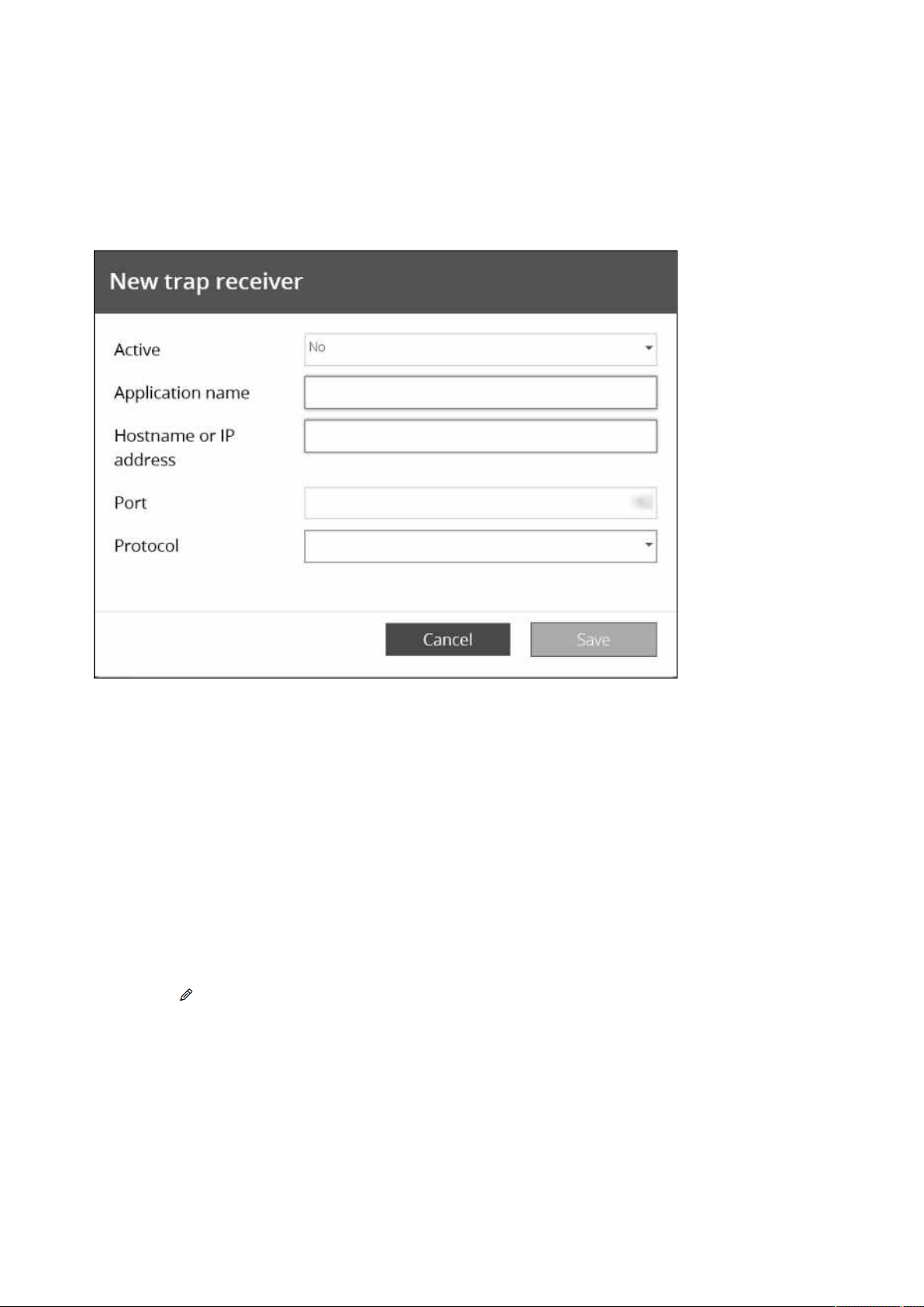
Settings
Contextual Help – 45
•
•
•
•
•
•
•
•
•
•
Protocol
Port
Status:Active/Inactive/Error(configuration error)
2.4.6.3 Actions
2.4.6.3.1 Add
1.Press theNewbutton to create new trap receivers.
2. Set following settings:
Active– Yes/No
Application name
Hostname or IP address
Port
Protocol– V1/V3
Trap community (V1) / User (V3)
3. Press theSAVEbutton.
2.4.6.3.2 Remove
Select a trap receiver and press the
Deletebutton to remove it.
2.4.6.3.3 Edit
Press the pen icon to edit trap receiver information and access to its settings.
2.4.6.3.4 Test all traps
Press the
Test all trapsbutton to send the trap test to all trap receivers.
Separate window provides the test status with following values:
In progress
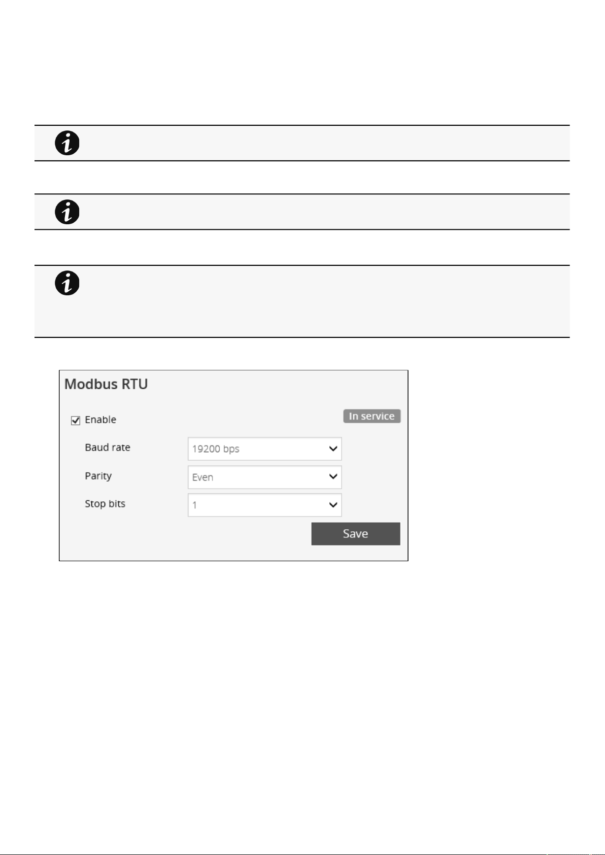
Settings
Contextual Help – 46
•
•
•
•
•
•
Request successfully sent
invalid type
2.4.6.4 Default settings parameters and limitations
2.4.7 Modbus
2.4.7.1 Modbus RTU
The following Modbus RTUsettings are configurable:
Enable
Baud rate
Parity
Stop bits
For details on SNMP trap codes, see the
Information>>>SNMP traps
section.
For details on default parameters and limitations, see the
Information>>>Default settings
parameters
section.
This section is only for the Modbus Network Module.
For instructions on connecting Modbus RTU see the sectionServicing the Network Management
Module>>>Wiring the RS-485 Modbus RTU terminal.
For instructions on configuring Modbus see the sectionServicing the Network Management
Module>>>Configuring Modbus TCP and RTU.
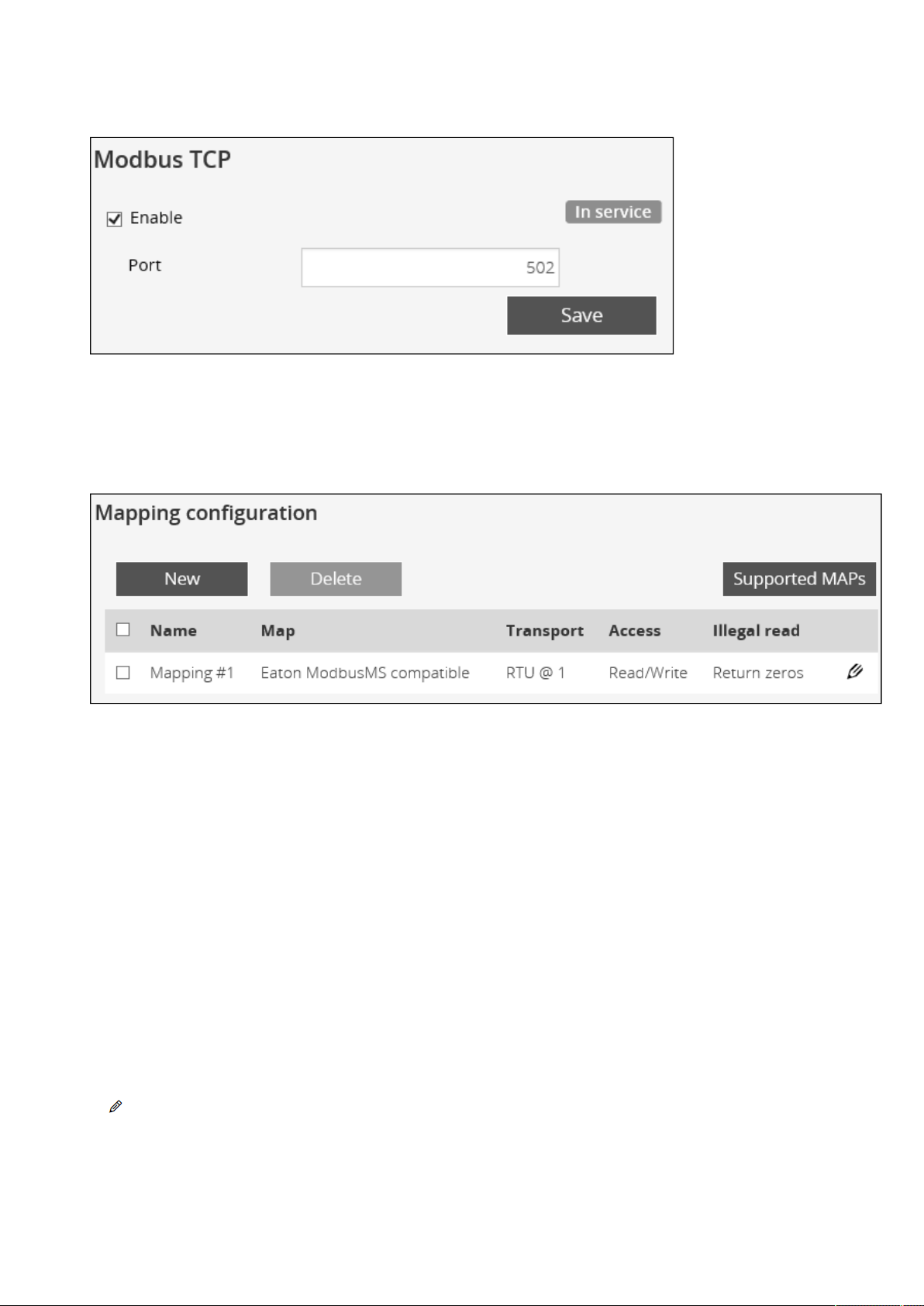
Settings
Contextual Help – 47
•
•
•
•
•
•
•
2.4.7.2 Modbus TCP
The followingModbus TCPsettings are configurable:
Enable
Port
2.4.7.3 Mapping configuration
2.4.7.3.1 Mapping configuration table
The table shows all the mapping configuration and includes the following details:
Name
Map
Transport
Access
Illegal read
2.4.7.3.2 Actions
a Add
Press the
Newbutton to create new mapping configuration.
b Remove
Select a mapping configuration and press the
Deletebutton to remove it.
c Edit
Press the pen logo to edit mapping configuration and access to the following settings:

Settings
Contextual Help – 48
•
•
•
•
•
•
•
•
•
•
•
•
•
•
•
•
•
•
•
•
•
•
Name
Map
Transport
Device ID
Access
Illegal read behavior
d Supported MAPs
Press the
Supported MAPsbutton to download the MAPs.
Mapping table content:
Address (hex): register address in hexadecimal
Address (1-base): register address in 1-base format
Type: Register/Discrete
Size in bytes
Number of Modbus registers
Writable: True/False
Representation: Int16/Uint16/String/Boolean/...
Name
Description
Unit
Status to 0: status when the register equal 0
Status to 1:status when the register equal 1
Available: True/False –Shows if the register is available on current UPS
Value: Shows current value of the register on current UPS
2.4.7.4 Default settings parameters and limitations
2.4.8 Certificates
2.4.8.1 Local certificates
Manage local certificates by :
Generating CSR and import certificates signed by the CA.
Generating new self-signed certificates.
File is generated in real time and will take into account the UPS capabilities and values at the time of the
generation.
Table in the downloaded file will show all possible registers, only the one showing Available equal to
True will be supported by your system.
For details on default parameters and limitations, see the
Information>>>Default settings
parameters
section.
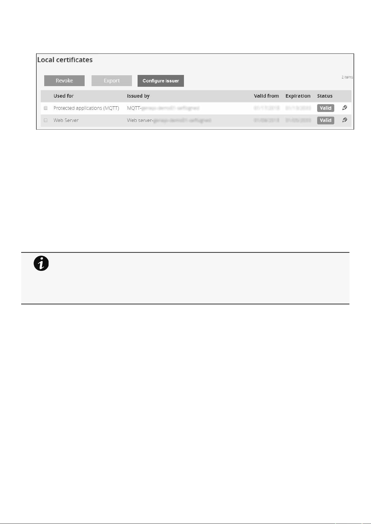
Settings
Contextual Help – 49
•
•
•
•
•
2.4.8.1.1 Local certificates table
The table shows the following information for each local certificate.
Used for
Issued by
Valid from
Expiration
Status — valid, expires soon, or expired
2.4.8.1.2 Actions
a Revoke
This action will take the selected certificate out of use.
Select the certificate to revoke, and then press the
Revokebutton.
A confirmation window appears, pressContinueto proceed, this operation cannot be recovered.
b Export
Exports the selected certificate on your OS browser window.
c Configure issuer
Press the
Configure issuerbutton.
A configuration window appears to edit issuer data.
Revoke will replace current certificate by a new self-signed certificate.
This may disconnect connected applications:
- Web browsers
- Shutdown application
- Monitoring application
The certificate that is taken out of use with the revoke action cannot be recovered.
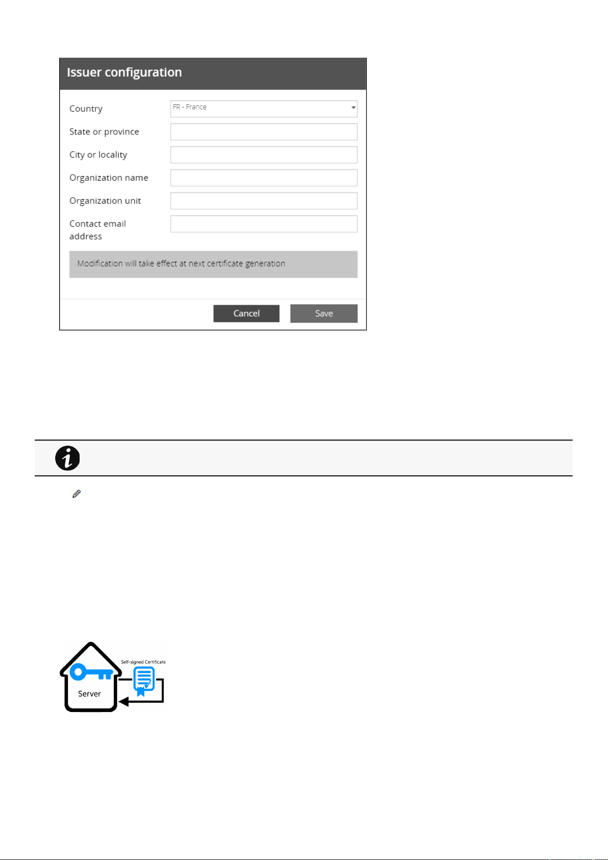
Settings
Contextual Help – 50
•
•
•
•
•
•
•
•
•
Country
State or Province
City or Locality
Organization name
Organization unit
Contact email address
PressSave button.
d Edit
Allows access to the following:
Certificate summary
Actions
Generate a new self-signed certificate.
Generate CSR.
Import certificate (only available when CSR is generated).
Details
2.4.8.1.3 Generate a new self-signed certificate
To replace a selected certificate with a new self-signed certificate.
This may disconnect applications such as a Web browser, shutdown application, or monitoring application.
This operation cannot be recovered.
Issuer configuration will be applied only after the revoke of the certificate.
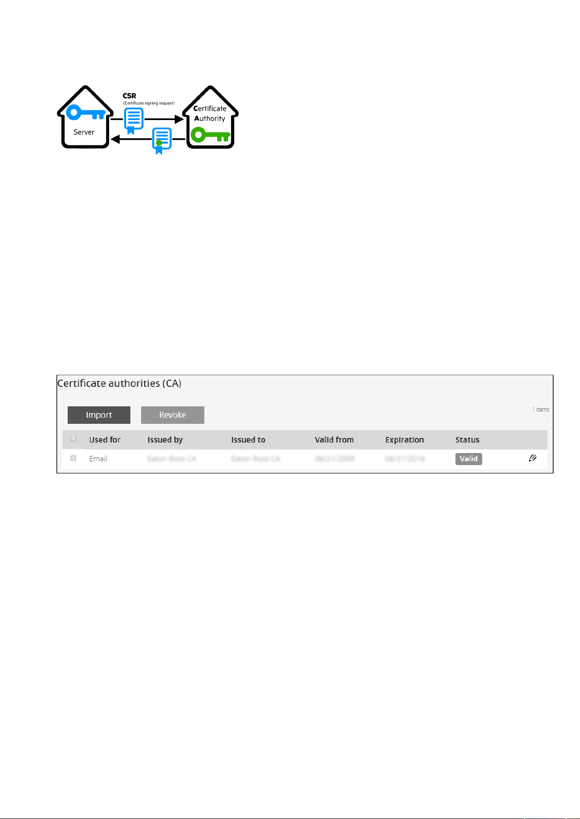
Settings
Contextual Help – 51
•
•
•
•
•
•
2.4.8.1.4 Create new certificates:
a CSR
Press
Generate Signing Request button in the in the certificate edition.
The CSR is automatically downloaded.
CSR must be signed with the CA, which is managed outside the card.
b Import certificate
When the CSR is signed by the CA, it can be imported into the Network Module.
When the import is complete, the new local certificate information is displayed in the table.
2.4.8.2 Certificate authorities (CA)
Manages CAs.
2.4.8.2.1 CA table
The table displays certificate authorities with the following details:
Used for
Issued by
Issued to
Valid from
Expiration
Status— valid, expires soon, or expired
2.4.8.2.2 Actions
a Import
When importing the CA, you must select the associated service, and then upload process can begin through the OS browser
window.
b Revoke
Select the certificate to revoke, and then press the
Revoke button.
A confirmation window appears, press Continue to proceed, this operation cannot be recovered.
Export
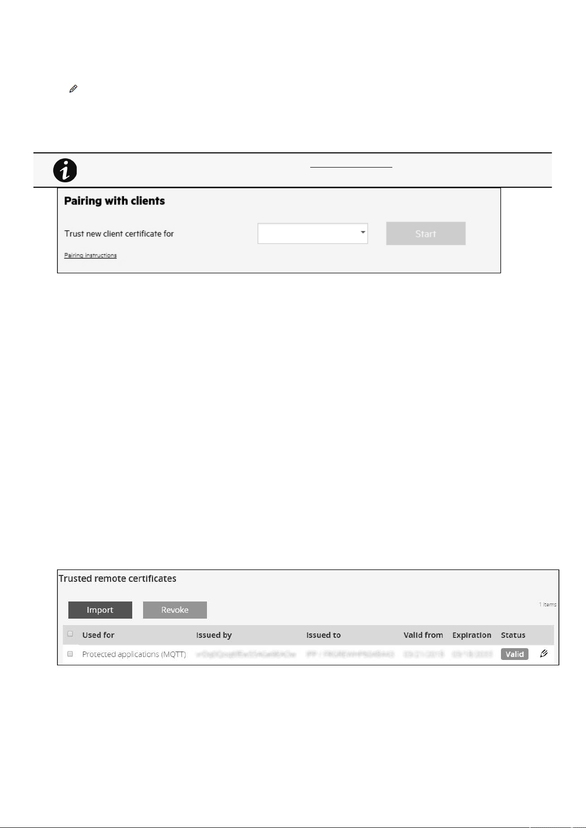
Settings
Contextual Help – 52
•
•
•
•
•
•
Exports the selected certificate on yourOS browser window.
c Edit
Gives access to a summary of the certificate.
2.4.8.3 Pairing with clients
During the selected timeframe, new connections to the Network Module are automatically trusted and accepted.
After automatic acceptance, make sure that all listed clients belong to your infrastructure. If not, access may be revoked using the
Delete button.
The use of this automatic acceptance should be restricted to a secured and trusted network.
For maximum security, we recommend followingone of the two methodson the certificate settings page:
Import agent's certificates manually.
Generate trusted certificate for both agents and Network Module using your own PKI.
2.4.8.3.1 Actions
a Start
Starts the pairing window during the selected timeframe or until it is stopped.
Time countdown is displayed.
b Stop
Stops
the pairing window.
2.4.8.4 Trusted remote certificates
The table shows the following information for each trusted remote certificate.
Used for
Issued by
Issued to
Valid from
For details on pairing instructions, follow the linkpairing instructionsin the tile or see theServicing the
Network Management Module
>>>Pairing agent to the Network Module
section.
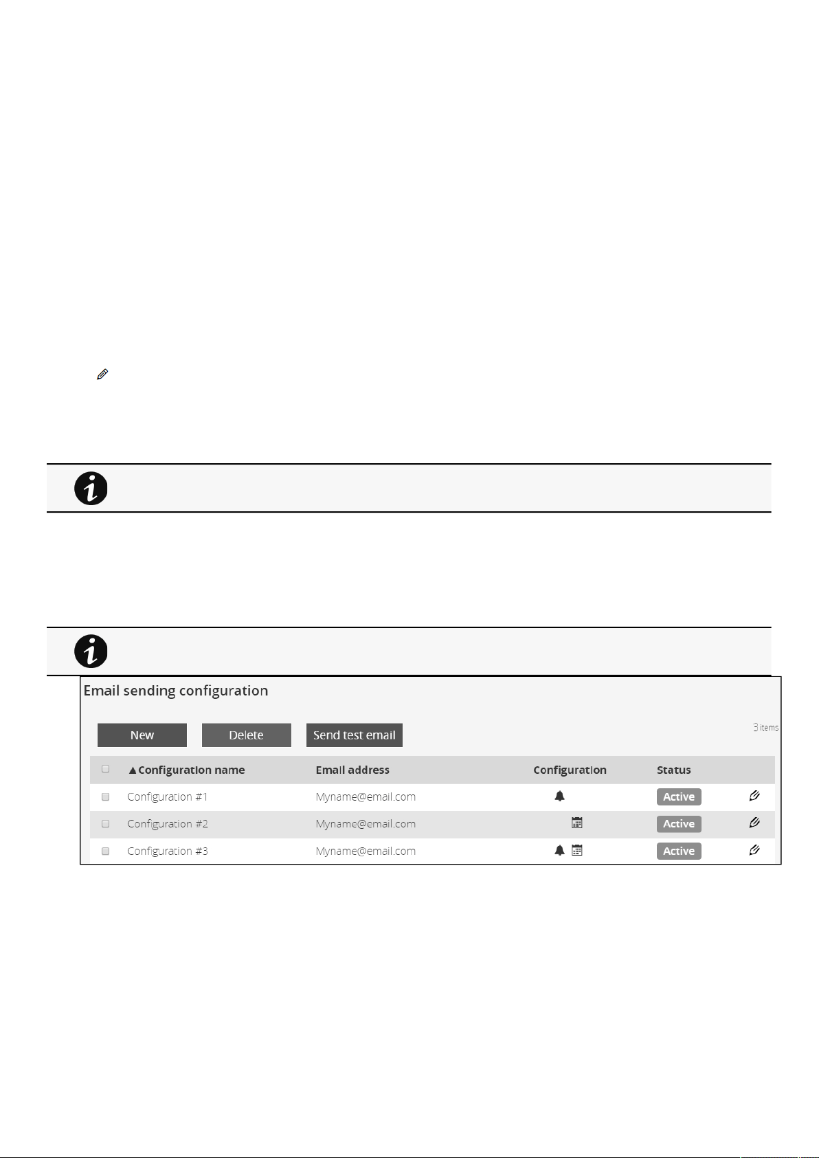
Settings
Contextual Help – 53
•
•
•
•
•
•
Expiration
In case a certificate expires, the connection with the client will be lost. If this happens, the user will have to recreate
the connection and associated certificates.
Status— valid, expires soon, or expired
2.4.8.4.1 Actions
a Import
When importing the client certificate, you must select the associated service, and then upload process can begin through the OS
browser window.
b Revoke
Select the certificate to revoke, and then press the
Revokebutton.
A confirmation window appears, pressContinueto proceed, this operation cannot be recovered.
c Edit
Gives access to a summary of the certificate.
2.4.8.5 Default settings parameters and limitations
2.4.9 Email
2.4.9.1 Email sending configuration
2.4.9.1.1 Email sending configuration table
The table shows all the email sending configuration and includes the following details:
Configuration name
Email address
Configuration
Configuration displays Email delegation/Events notification/Periodic report icons when active.
Status– Active/Inactive/In delegation
For details on default parameters and limitations, see the
Information>>>Default settings
parameters
section.
For examples on email sending configuration see theServicing the Network Management
Module>>>Subscribing to a set of alarms for email notification section.

Settings
Contextual Help – 54
•
•
•
•
•
2.4.9.1.2 Actions
a Add
Press the
Newbutton to create a new email sending configuration.
b Remove
Select an email sending configuration and press the
Deletebutton to remove it.
c Edit
Press the pen icon to edit email sending configuration and access to the following settings:
Active
Configuration name
Email address
Notify on events– Severity level/Attach logs/Exceptions on events notification
Periodic report– Active/Recurrence/Starting/Topic selection– Card/Devices
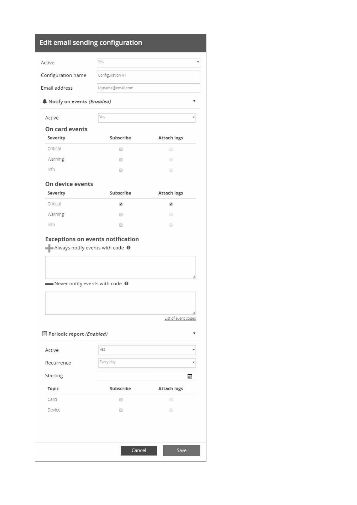
Settings
Contextual Help – 55
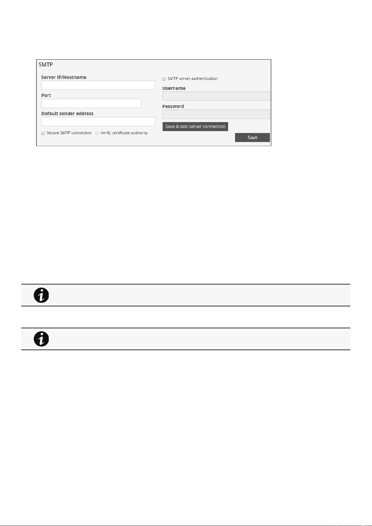
Settings
Contextual Help – 56
•
•
•
•
•
•
•
SMTP
SMTP is an internet standard for electronic email transmission.
The following SMTP settings are configurable:
Server IP/Hostname – Enter the host name or IP address of the SMTP server used to transfer email messages in the
SMTP Server field.
Port
Sender address
Secure SMTP connection
Verify certificate authority
SMTP server authentication
Select the SMTP server authentication checkbox to require a user name and a password for SNMP authentication.
Enter the Username and the Password.
Save and test server configuration
2.4.9.2 Default settings parameters and limitations
2.4.10 My preferences
For details on default parameters and limitations, see the
Information>>>Default settings
parameters
section.
This page is in read-only mode when connected through LDAP and it displays the preferences applied to
all LDAP users as configured in the
Settings>>>Users>>>LDAP-Users preferences
section.
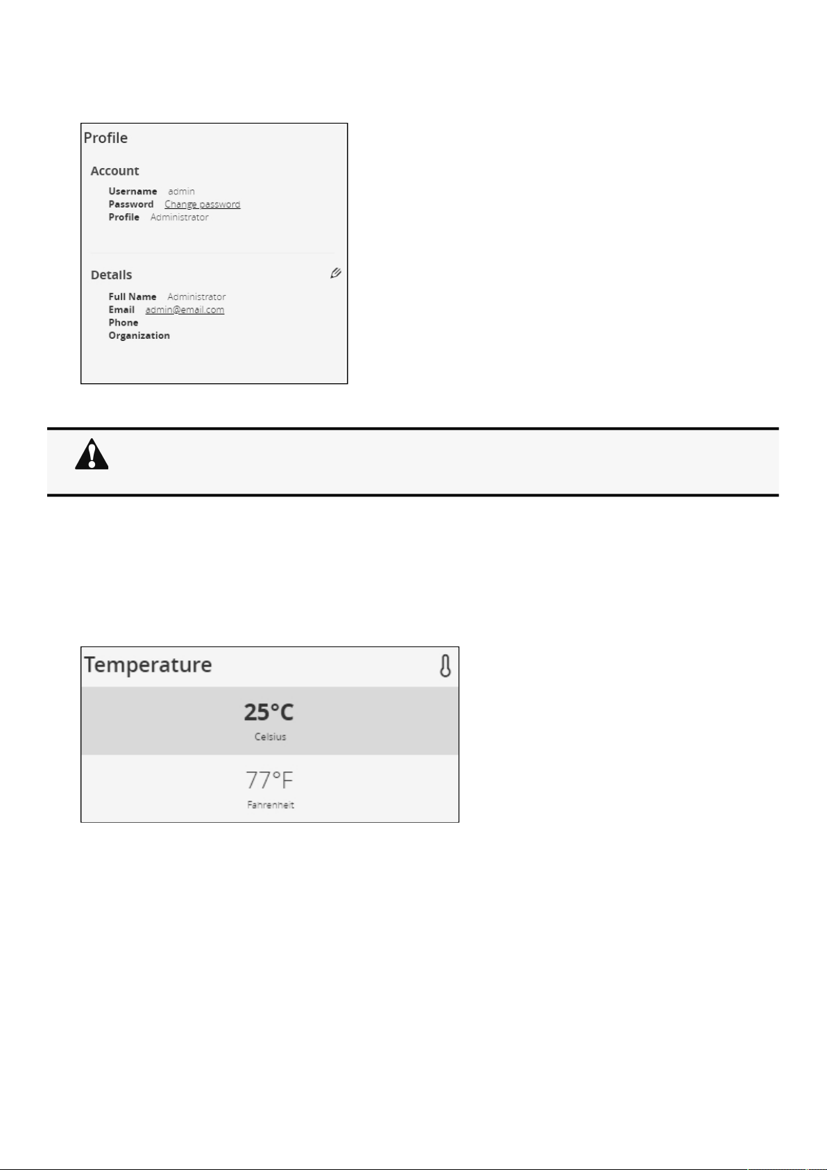
Settings
Contextual Help – 57
•
•
•
•
•
•
2.4.10.1 Profile
Click on Change password to change the password.
If you have the administrator's rights, you can press the pen logo toedit user profile and update the following information:
Full name
Email
Phone
Organization
2.4.10.2 Temperature
°C (Celsius)
°F (Fahrenheit)
In some cases, it is not possible to change the password if it has already been changed within a day
period.
Refer to the troubleshooting section.
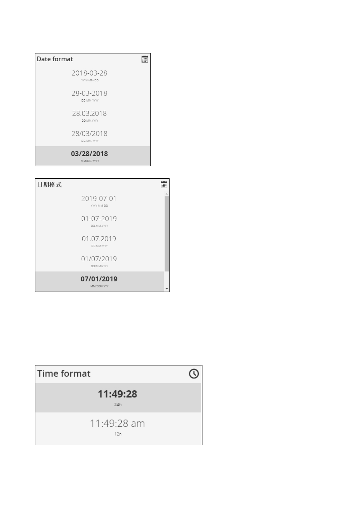
Settings
Contextual Help – 58
•
•
•
•
•
•
2.4.10.3 Date format
YYYY-MM-DD
DD-MM-YYYY
DD.MM.YYYY
DD/MM/YYYY
MM/DD/YYYY
DD MM YYYY
2.4.10.4 Time format
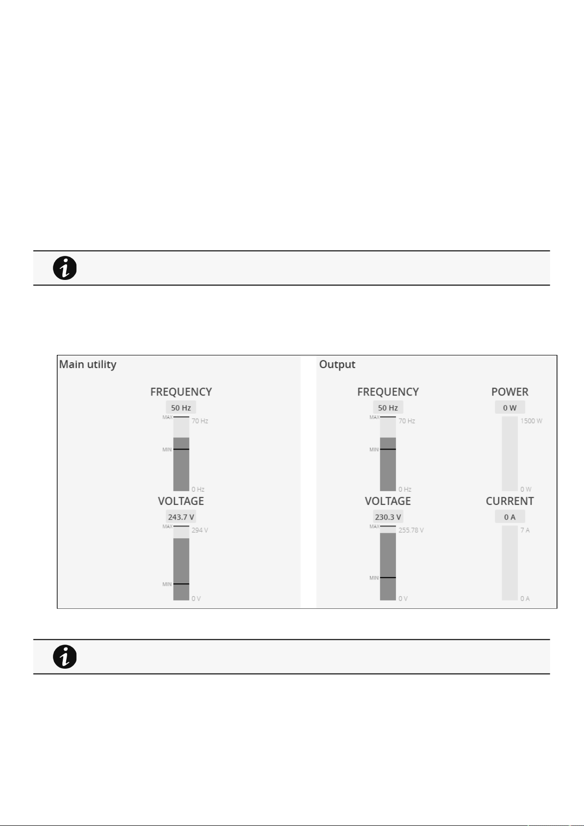
Meters
Contextual Help – 59
•
•
•
•
•
•
•
•
•
•
•
•
hh:mm:ss (24h)
hh:mm:ss (12h)
2.4.10.5 Language
German
English
Spanish
French
Italian
Japanese
Simplified Chinese
Traditional Chinese
2.4.10.6 Default settings parameters and limitations
2.5 Meters
2.5.1 Power
Displays the product input and output measures.
2.5.1.1 Input
Frequency (Hz)
Voltage (V)
For details on default parameters and limitations, see the
Information>>>Default settings
parameters
section.
The numbers on the right side of a gauge show the scale.
They do not indicate allowed or observed minimum or maximum levels.
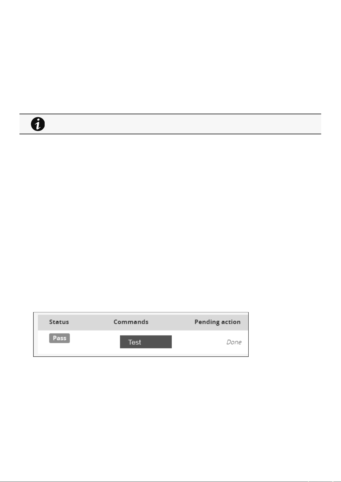
Meters
Contextual Help – 60
•
•
•
•
•
•
•
•
•
•
•
•
•
•
•
•
•
•
•
•
•
•
•
•
•
2.5.1.2 Output
Frequency (Hz)
Voltage (V)
Power (W)
Current (A)
2.5.2 Battery
Battery section is an overviewof the battery information and allow to launch a battery test.
2.5.2.1 Overview
Type
Nominal capacity
Nominal voltage
Capacity remaining
Runtime
State
Recommended replacement date
State of health
2.5.2.2 Details
Voltage
Current
Temperature
Min cell voltage
Max cell voltage
Number of cycles
Min temperature
Max temperature
BMS state
2.5.2.3 Test
2.5.2.3.1 Status
Battery test status reflects thelast completed battery test result,as well as itscritical status (color) and completion time.
Pass
Warning
Fail
Unknown
The information displayed depends on the device.
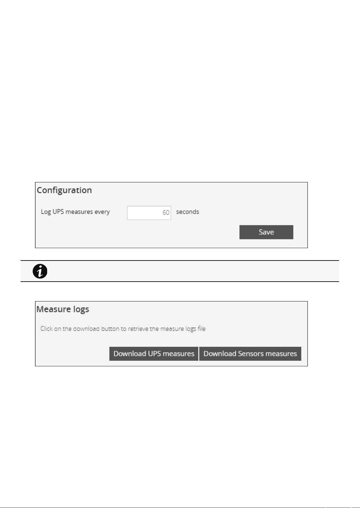
Meters
Contextual Help – 61
•
•
•
•
•
•
•
•
•
•
•
•
•
•
•
2.5.2.3.2 Commands
Start
button is disabled if a battery test is already in progress or scheduled.
The Abort
button is enabled only when a test is in progress or scheduled.
2.5.2.3.3 Pending action
The pending action reflects thebattery test status
.
None
Scheduled
In progress
Aborted
Done
2.5.3 Measure logs
2.5.3.1 Configuration
This log configuration allows to define the log acquisition frequency of the UPS measures only.
2.5.3.2 Measure logs
Press theDownload UPS measuresbutton to download the UPS log file.
If available, possible measures are listed below:
Input Voltage (V)
Input Frequency (Hz)
Bypass Voltage (V)
Bypass Frequency (Hz)
Output Voltage (V)
Output Frequency (Hz)
Output Current (A)
Output Apparent Power (VA)
Output Active Power (W)
Output Power Factor
The sensors measures logs acquisition is not settable and done every minutes.
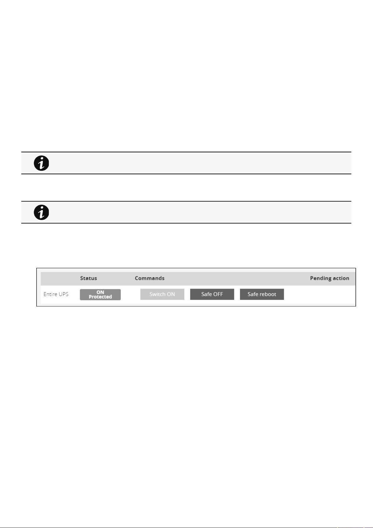
Controls
Contextual Help – 62
•
•
•
•
•
•
•
•
•
•
•
•
Output Percent Load (%)
Battery Voltage (V)
Battery Capacity (%)
Battery Remaining Time (s)
Press theDownload Sensors measuresbutton to download the sensors log file.
If available, possible measures are listed below:
Temperature of <sensor_1> (in K, 1 decimal digit)
Humidity of <sensor_1> (in %, 1 decimal digit)
Temperature of <sensor_2>> (in K, 1 decimal digit)
Humidity of <sensor_2>(in %, 1 decimal digit)
Temperature of <sensor_3>(in K, 1 decimal digit)
Humidity of <sensor_3>(in %RH, 1 decimal digit)
2.5.3.3 Default settings parameters and limitations
2.6 Controls
2.6.1 UPS
2.6.1.1 Entire UPS
Controls are displayed for the entire UPS, and not for specific outlet options.
The table in this section displays UPS status, the associated commands (on/off), and the pending action.
2.6.1.1.1 Status
Reflects the current mode of the UPS.The following is a list of potential table values that are displayed based on the UPS topology.
On— Protected/Not protected
Off— Not powered/Not protected
2.6.1.1.2
a Safe OFF
This will shut off the load. Protected applications will be safely powered down.
This control is available only if the status is not OFF and if there are no active commands running.
°C = K - 273.15
°F = K x 9/5 -459.67
For details on default parameters and limitations, see the
Information>>>Default settings
parameters
section.
Commands
A set of commands are available and activated when one of the followingbuttons is pressed.A confirmation window appears.
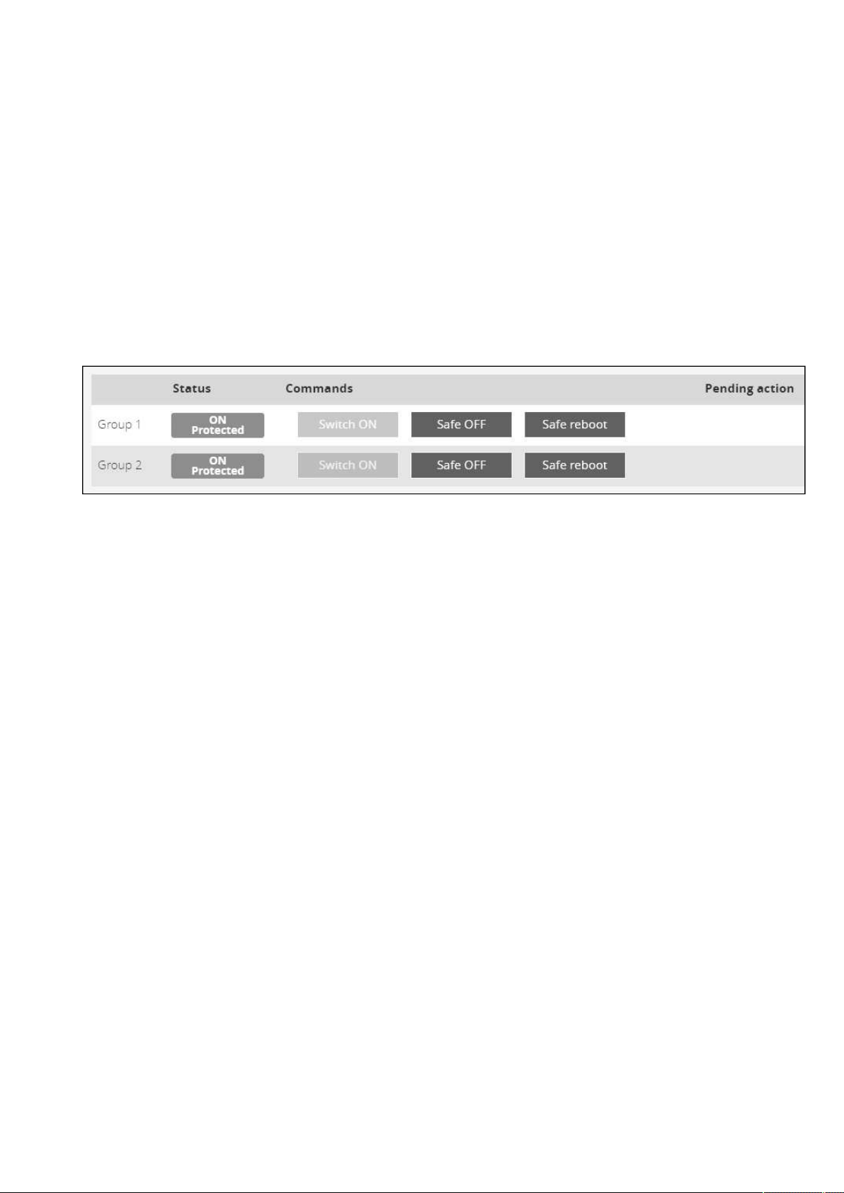
Controls
Contextual Help – 63
•
•
b Safe reboot
This will shut off and then switch ON the load. Protected applications will be safely powered down.
This control is available only if the status is not OFF and if there are no active commands running.
c Switch ON
This will switch ON the load or turn ON the online UPS.
This control is available when the status is OFF, if there are no active commands running and if the Online UPS is on bypass.
2.6.1.1.3 Pending action
Displays the delay before shutdown and delays before startup.
2.6.2 Outlets
2.6.2.1 Group 1/ Group 2
Load segmentations allow, battery runtime to remain on essential equipment and automatically power down non-priority equipment
during an extended power outage.
This feature is also used for remote reboot and the sequential start of servers to restrict inrush currents.
2.6.2.1.1 Status
It reflects the current outlet status:
On — Protected/Not protected
Off — Not powered
2.6.2.1.2
a Safe OFF
This will shut off the load connected to the associated load segment. Protected applications are safely powered down.
This control is available only if the status is not OFF and if there are no active commands running.
b Safe reboot
This will power down and then switch ON the load connected to the associatedload segment. Protected applications are safely
powered down.
This control is available only if the status is not OFF and if there are no active commands running.
c Switch ON
This will switch ON the load connected to the associatedload segment.
This control is available when status is OFFand if there are no active commands running.
Commands
A set of commands are available and activated when one of the following buttons is pressed.A confirmation window appears.
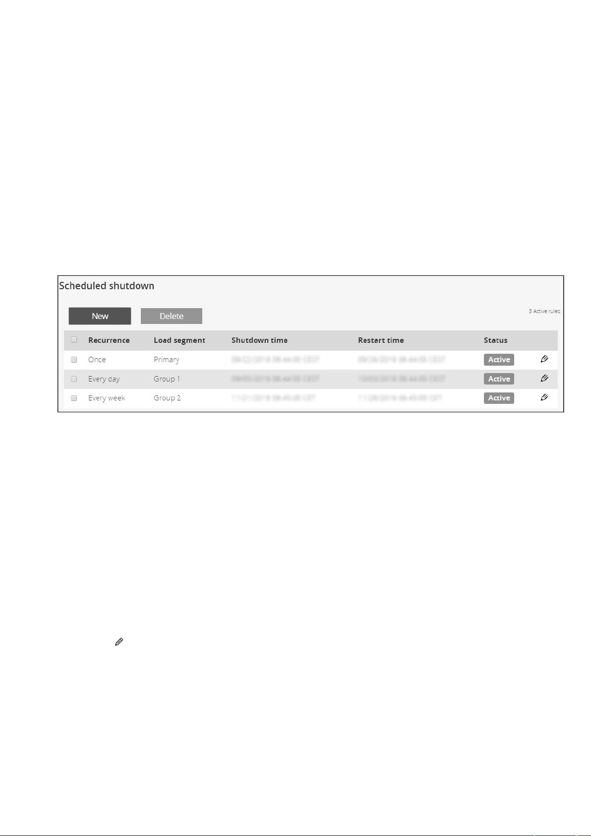
Protection
Contextual Help – 64
•
•
•
•
•
2.6.2.1.3 Pending action
Displays the delay before shutdown and delay before startup.
2.7 Protection
2.7.1 Scheduled shutdowns
Use Scheduled shutdowns to turn off either the UPS or individual load segments at a specific day and time.
This feature is used for saving energy by turning off equipment outside of office hours or to enhance cybersecurity by powering
down network equipment.
If server shutdown scenarios are defined for any of the connected servers or appliances, they will be triggered before the
corresponding outlets are turned off as configured in shutdown settings.
2.7.1.1 Scheduled shutdowns table
The table displays the scheduled shutdowns and includes the following details:
Active – Yes/No
Recurrence–Once/Every day/Every week
Load segment –Primary/Group 1/Group 2
Shutdown–Date/Time
Restart–Date/Time
2.7.1.2 Actions
2.7.1.2.1 New
Press the
New button to create a scheduled shutdown.
2.7.1.2.2 Remove
Select a schedule shutdown and press the
Remove button to delete the scheduled shutdown.
2.7.1.2.3 Edit
Press the pen icon to editschedule shutdown and to access the settings.
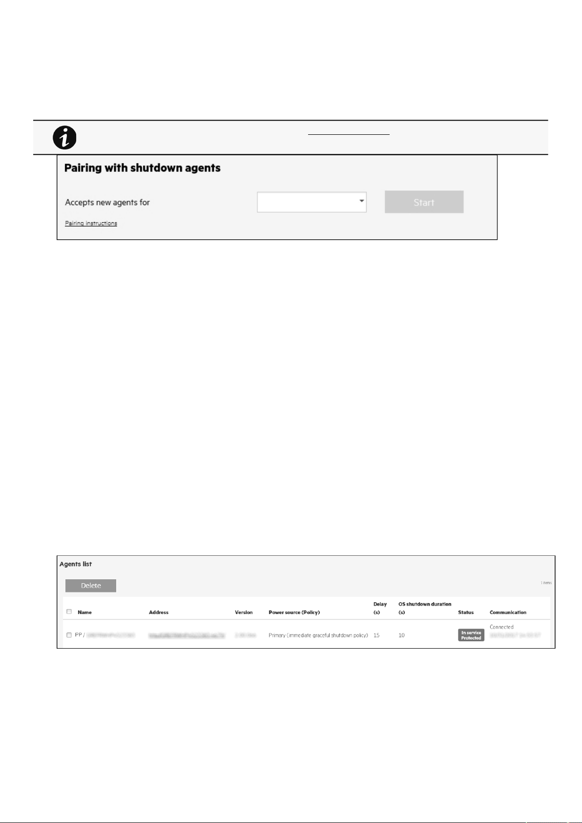
Protection
Contextual Help – 65
•
•
•
•
•
•
•
•
2.7.2 Agent list
2.7.2.1 Pairing with shutdown agents
Authentication and encryption of connections between the UPS network module and shutdown agents is based on matching
certificates. Automated pairing of shutdown agents and UPS network modules is recommended in case the installation is done
manually in a secure and trusted network, and when certificates cannot be created in other ways.
During the selected timeframe, new agent connections to the Network Module are automatically trusted and accepted.
After automatic acceptance, make sure that all listed agents belong to your infrastructure. If not, access may be revoked using the
Delete button.
For maximum security,Eatonrecommend followingone of the two methodson the certificate settings page:
import client certificates manually.
generate trusted certificate for both clients and Network Module using your own PKI.
2.7.2.1.1 Actions
a Start
Starts the pairing window for the selected timeframe or until it is stopped.
Time countdown is displayed.
b Stop
Stops
the pairing window.
2.7.2.2 Agent list table
The table displays theIPPagent list that is connected to the Network Moduleand includes the following details:
Name
Address
Version of the Agent
Power source (Policy)
Delay (in seconds)
OS shutdown duration (in seconds)
For details on pairing instructions, follow the link pairing instructions in the tile or see the Servicing the
Network Management Module
>>>Pairing agent to the Network Module
section.
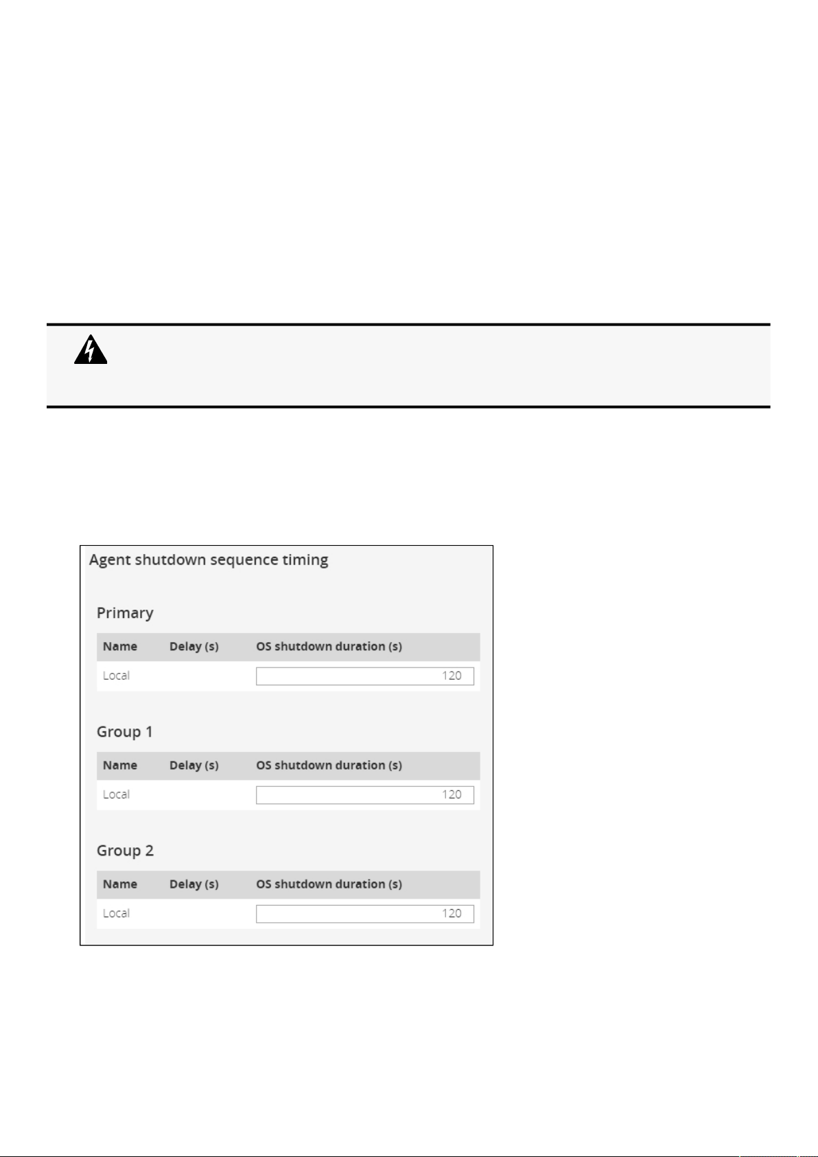
Protection
Contextual Help – 66
•
•
•
•
•
•
•
•
•
•
•
Status
In service | Protected
In service | Not protected
Stopping | Protected
Stopped | Protected
Communication
Connected | yyyy/mm/dd hh:mm:ss
Lost|yyyy/mm/dd hh:mm:ss
2.7.2.3 Actions
2.7.2.3.1 Delete
When communication with the agent is lost, agent can be deleted by using the
Delete button.
Select an agent and press the Deletebutton to delete the agent.
2.7.3 Agent settings
2.7.3.1 Agent shutdown sequence timing
All agents that are connected to the Network Module are displayed in tables by power sources.
Primary
Group 1
Group 2
When the agent is connected, the Delete function will not work correctly because the agent will keep
on trying to re-connect.
So connect to the software, remove the Network module from the Software nodes list (in the nodes
list, right click on the Network module and click remove nodes).
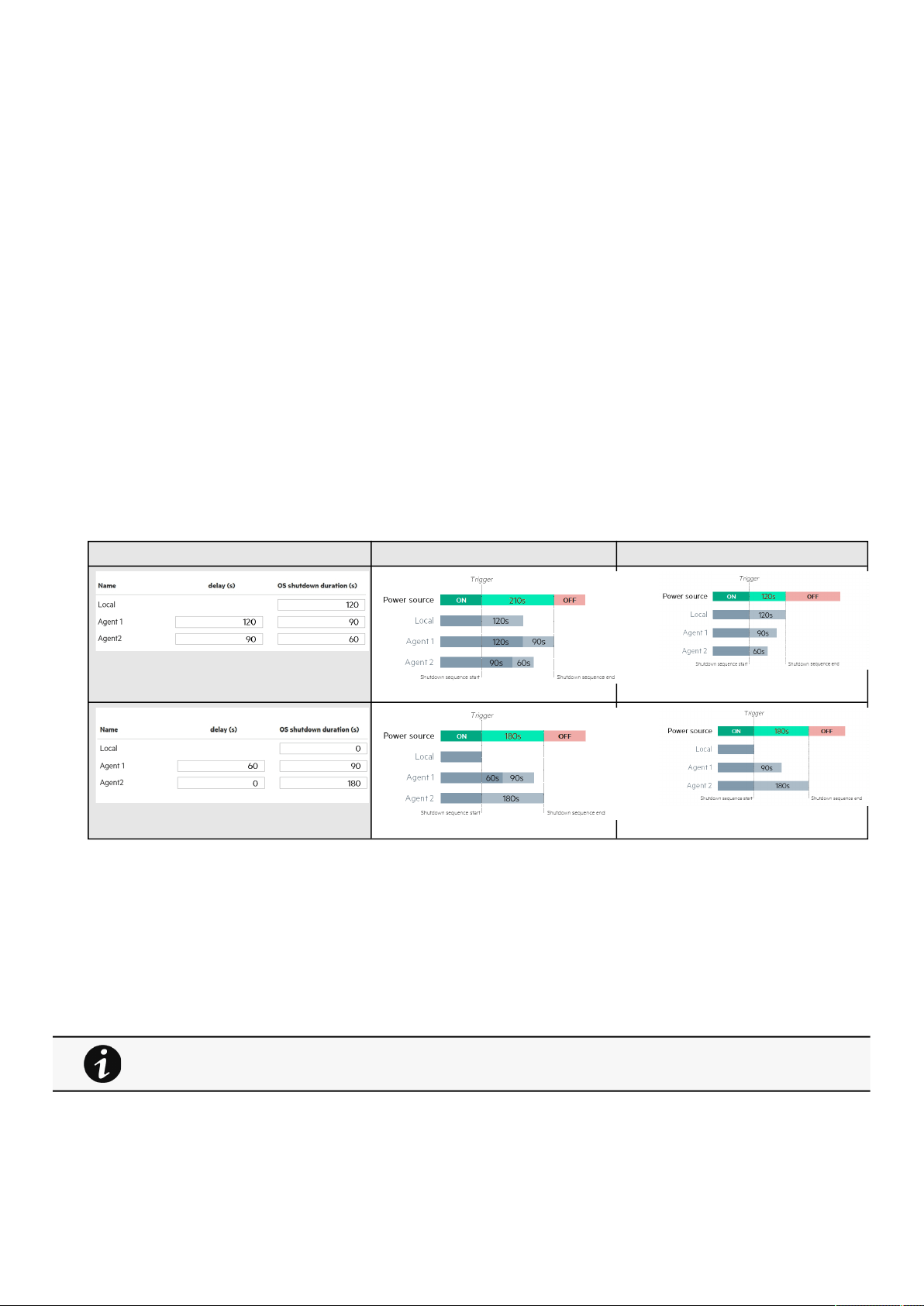
Protection
Contextual Help – 67
•
•
•
The 'local agent' settingis used for settingfor example a minimum shutdown duration, or a power down delay for a load segment
that has no registered shutdown agents. One use case would be a load segment that powers network equipment that needs to
stay on while servers and storage perform their orderly shutdown.
The tables include the following details:
Name
Delay (in seconds)
OS shutdown duration (in seconds)
2.7.3.2 Actions
2.7.3.2.1 Set Delay
Select and directly change the setting in the table and then
Save.
2.7.3.2.2 Set OS shutdown duration
Select and directly change the setting in the tableand then
Save.
2.7.3.3 Examples
Examples below show the impact of agent settings on the shutdown sequence for an ordered shutdown or an immediate
shutdown.
Agent settings examplesSequential shutdownImmediate shutdown
Note:
The trigger in the diagram isthe moment whenthe shutdown sequence starts, and it is defined in the power outage policy section
for each power source.
2.7.4 Power outage policy
These setting are in conjunction with the shutdown agents andcontrol how the network module directs the shutdown of protected
servers and appliances. It gives the possibility to prioritize and schedule shutdown actions so that the IT system is powered down
in the correct order. For example, applications first, database servers next, and storage last. It is also possible to turn off some
outlets to reduce power consumption and get longer battery runtime for the most important devices.
For examples on Powering down applications see theServicing the Network Management
Module>>>Powering down/up applications examples section.
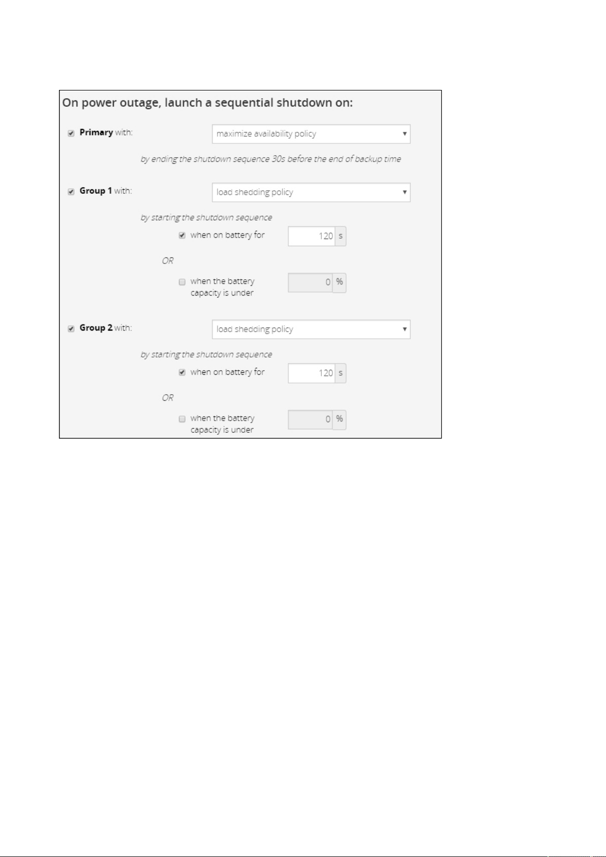
Protection
Contextual Help – 68
•
•
•
•
2.7.4.1 On power outage
Policies are set per power source (outlet groups) if they are present in the UPS.
2.7.4.1.1 Enable/Disable
For each power source, the shutdown policy can be enabled or disabled with check-boxes.
When disabled, the policy will be greyed out.
2.7.4.1.2 Set the policy
The available policies for shutdown are listed below from preset to customized settings:
Preset policies
Maximize availability—To end the shutdown 30s before the end of backup time.
Immediate graceful shutdown—To start the shutdown after 30s of backup time.
Custom policies
When there are several conditions to start the shutdown sequence, the shutdown sequence will start as soon as one of the
conditions is reached.
Load shedding —To start the shutdown when on battery for the set time in (s) or when battery capacity reaches the
set capacity in (%). When disabled, the condition is greyed out.
Custom —Same as load shedding but with 2 additional options:
-to end the shutdown after the set time in (s) before the end of backup time.
- to start shutdown after the set time in (s) before the end of backup time.
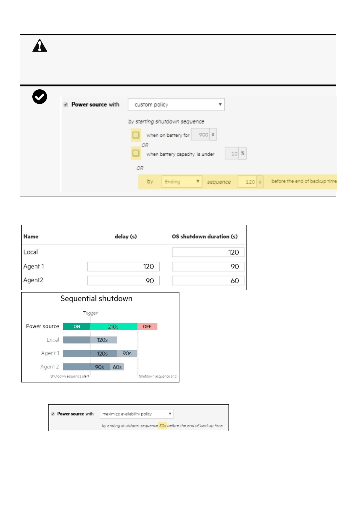
Protection
Contextual Help – 69
2.7.4.1.3 Settings examples
All the following examples are using below agent's settings.
a Example 1: Maximize availability policy
•
•
When primary shuts OFF, both group1 and group 2 shut OFF immediately.
So if Primary is set to one of the following:
Immediate graceful shutdown — groups policies should be restricted toImmediate graceful
shutdown.
Load shedding — groups policies should avoid Maximize availability.
On custom policy, if the 2 checkboxes are unchecked, only the last condition is taken into account.
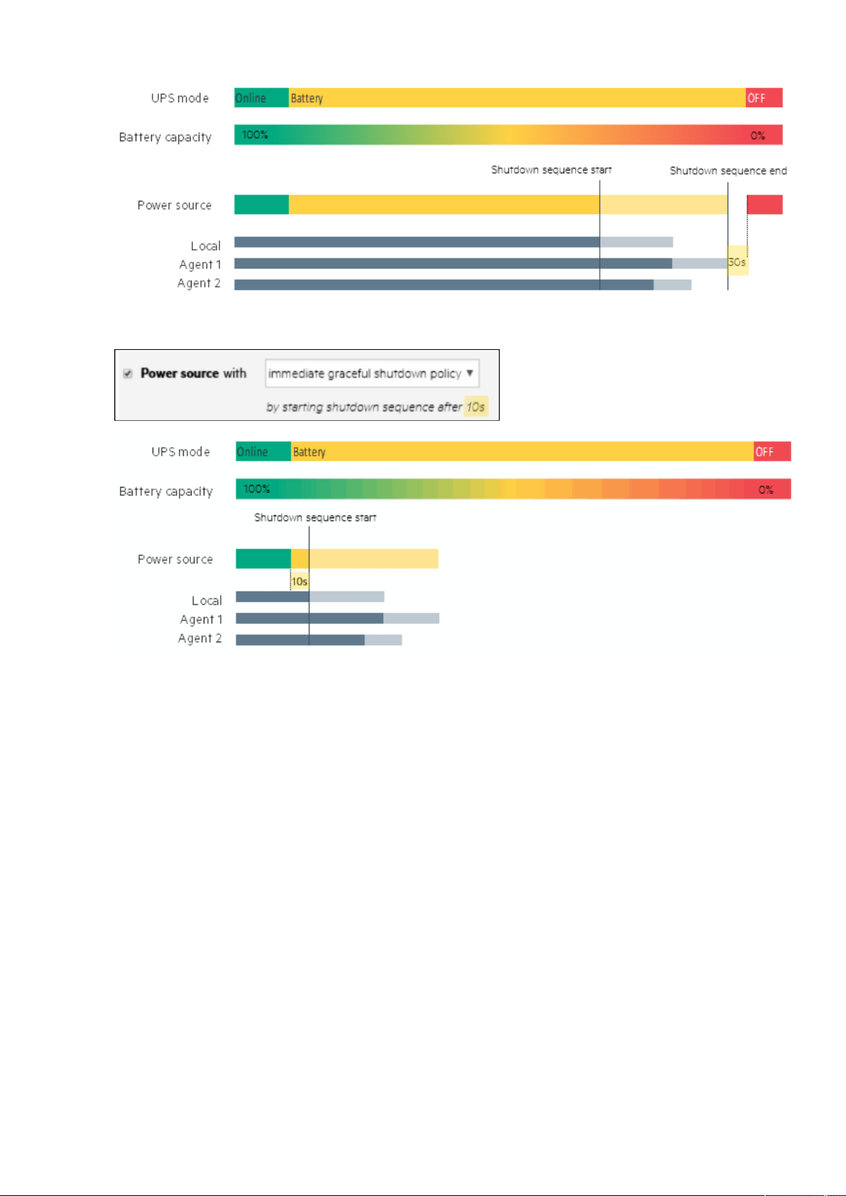
Protection
Contextual Help – 70
b Example 2: Immediate graceful shutdown policy
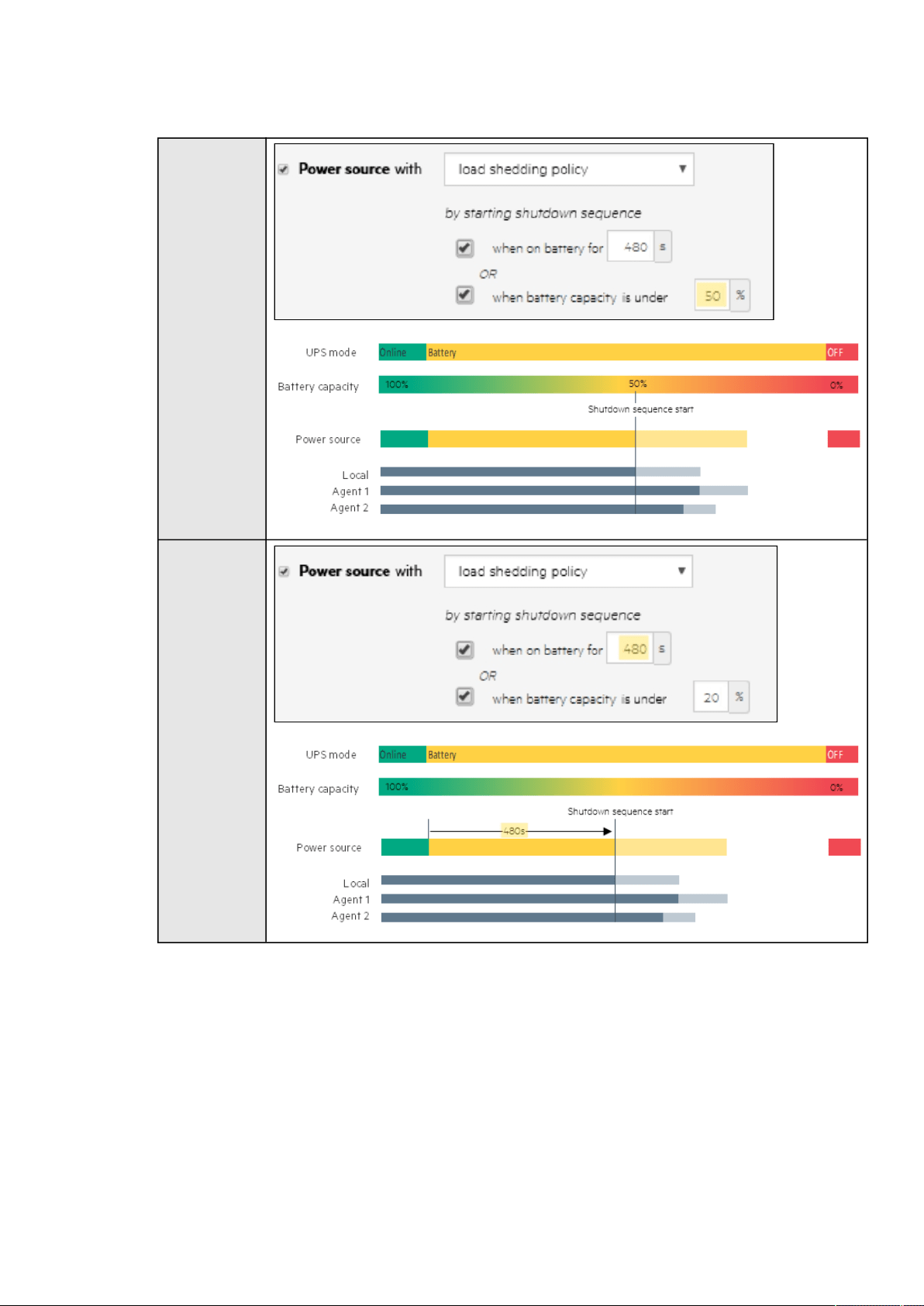
Protection
Contextual Help – 71
c Example 3: Load shedding policy
Settings #1
Settings #2
d Example 4: Custom policy
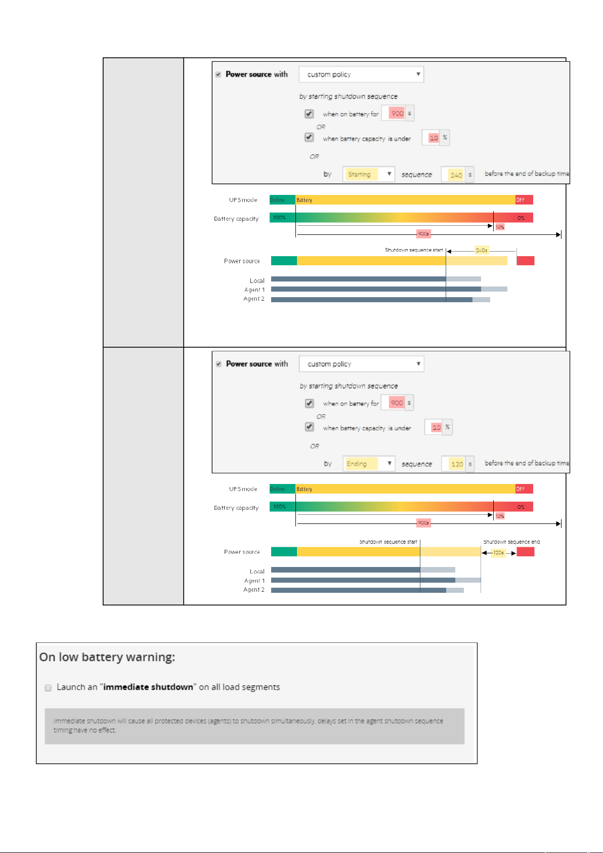
Protection
Contextual Help – 72
Settings #1
Settings #2
2.7.4.2 On low battery warning
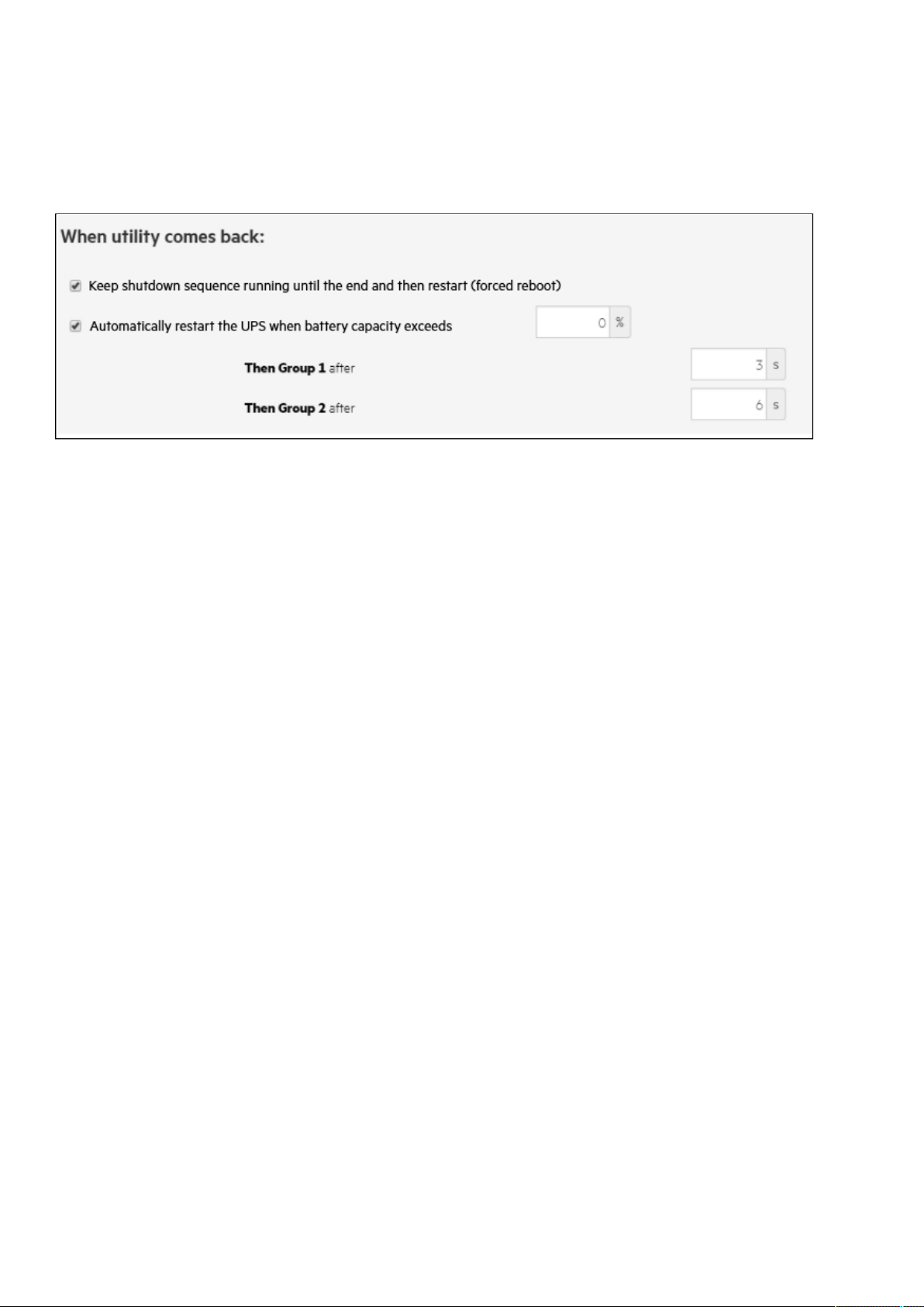
Card
Contextual Help – 73
•
•
•
•
•
•
•
•
•
•
•
In some cases, like a renewed power failure or failed battery, the capacity is much lower than anticipated. The UPS gives a Low
battery warning when there is 2 - 3 minutes of estimated runtime left, depending on the UPS and its settings. This time is typically
enough for shutting down a server but does not allow sophisticated sequential shutdown schemes.
The Low battery policy is intended for these cases.
2.7.4.3 When utility comes back
These settings define the restart sequence when utility comes back. For example, thisallows sequential startup of the IT system
so that network and storage devices are connected to 'Primary' and start up immediately. After a delay database servers in Group1
are powered up, and then application and web servers in Group 2 are powered up. This startup would ensure that necessary
services would be available for each layer when needed. A sequential startup will also help avoid a peak power draw in the
beginning.
2.7.4.3.1 Options
Keep shutdown sequence running until the end, and then restart (forced reboot).
Wait until UPS battery capacity exceeds a set percentage value in (%), and then automatically restart the UPS.
Then restartGroup 1 after a set time in (s).
Then restart Group 2 after a set time in (s).
2.7.4.3.2 Enable/Disable
Each option listed above can be enabled or disabled with check-boxes.
When disabled, the option will be greyed out.
2.8 Card
2.8.1 System information
System information is an overviewof the main Network Module information.
The
COPY TO CLIPBOARD button will copy the information to the clipboard.
2.8.1.1 Identification
System name– if filled, it replaces the UPS model name in the top bar
Product
Physical name
Vendor
UUID
Part number
Serial number
Hardware version
Location
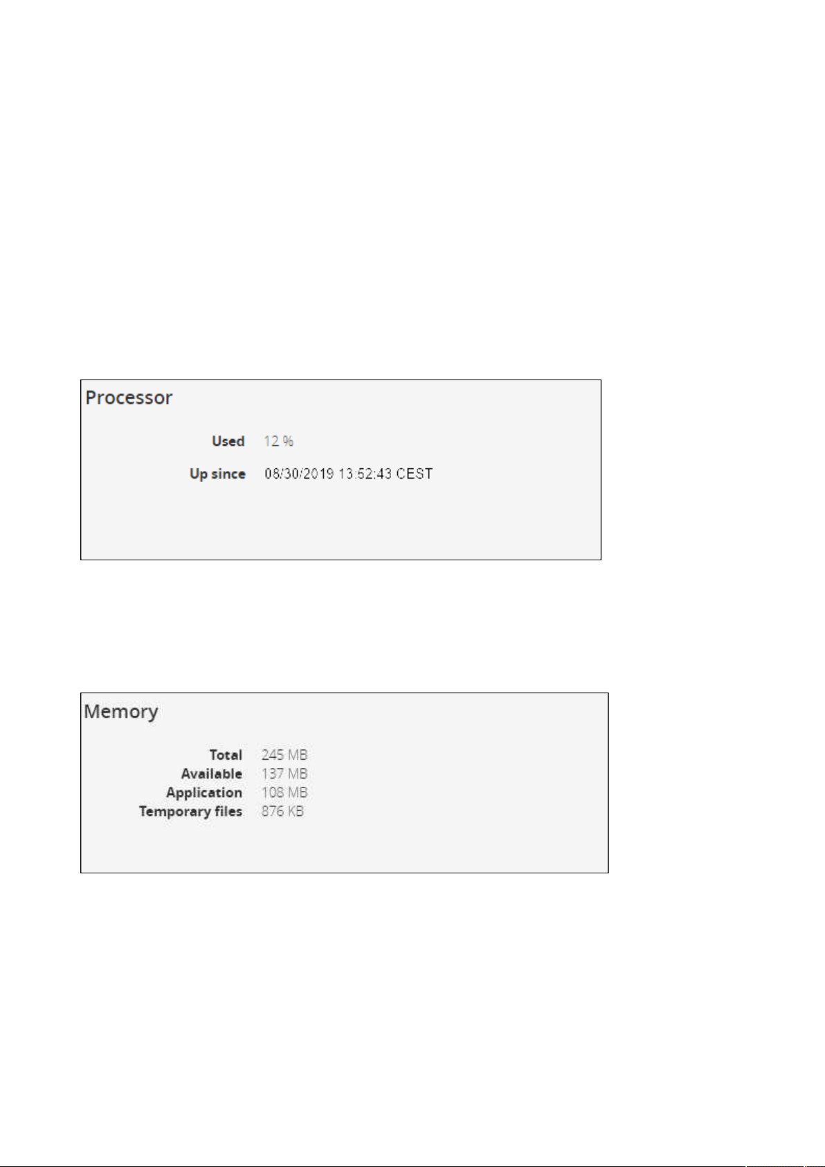
Card
Contextual Help – 74
•
•
•
•
•
•
•
•
•
•
•
•
•
Contact
2.8.1.2 Firmware information
Version
SHA
Build date
Installation date
Activation date
Bootloader version
2.8.2 Resources
Card resources is an overviewof the Network Module processor, memory and storage information.
2.8.2.1 Processor
Used in %
Up since date
2.8.2.2 Memory
Total size in MB
Available size in MB
Application size in MB
Temprorary files size in MB
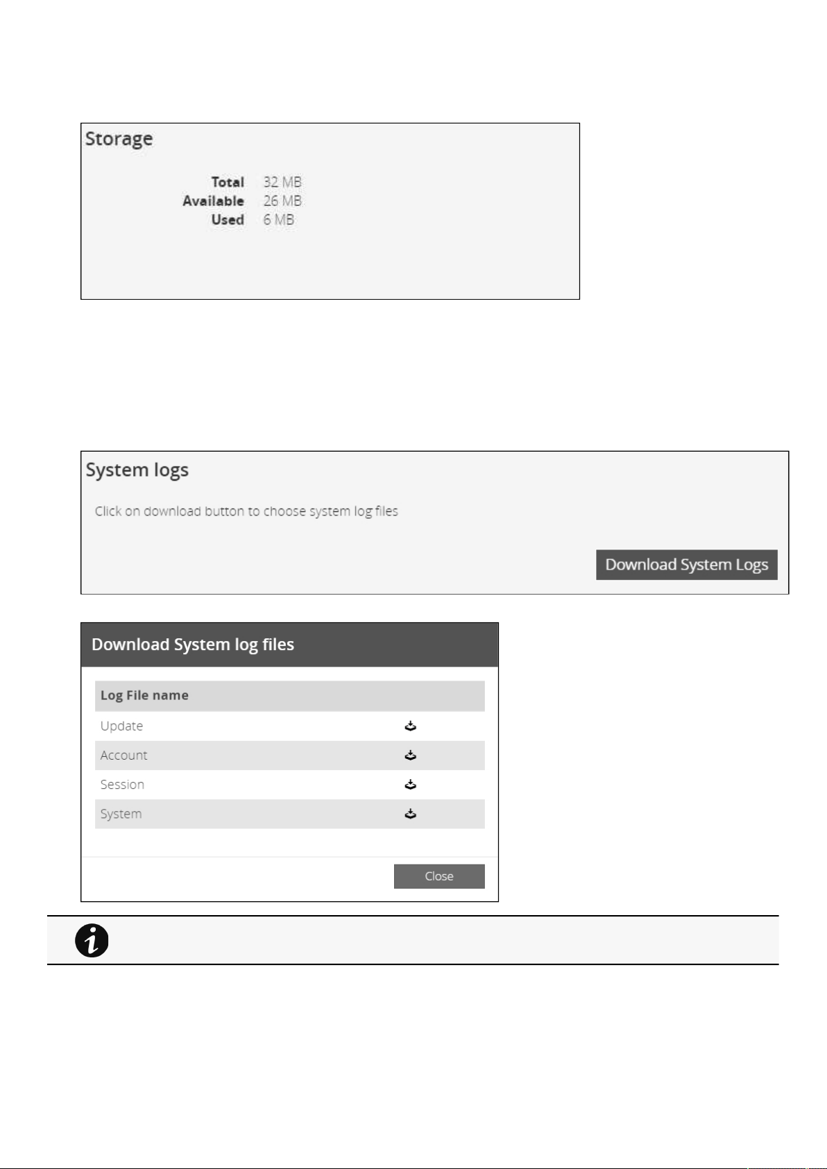
Card
Contextual Help – 75
•
•
•
2.8.2.3 Storage
Total size in MB
Available size in MB
Used size in MB
2.8.3 System logs
Press the Download System Logsbutton to select the log files to download.
For the list of system logs, see the Information>>>System Logs codes section.

Card
Contextual Help – 76
•
•
•
•
•
•
•
2.8.4 Administration
2.8.4.1 Network module firmware
Monitors the information for the two-embedded firmware.
Upgrade the Network Module firmware.
2.8.4.1.1 Firmware information
a Status
Uploading
Invalid
Valid
Pending reboot
Active
b Version
Displays the associated firmware version.
c Release date
Displays the release date of the firmware.
For better performance, security, and optimized features,Eaton
recommends to upgrade the Network Module regularly.
d
Installation date
Displays when the firmware was installed in the Network Module.
e Activation date
Displays when the firmware was activated in the Network Module.
2.8.4.1.2 Upgrade the Network Module firmware
During the upgrade process, the Network Module does not monitor theUPS Product status.
To upgrade the firmware:
1.Download the latest firmware version from the website.For more information, see the
Servicing the Network Management
Module>>>Accessing to the latest Network Module firmware/driver
section.
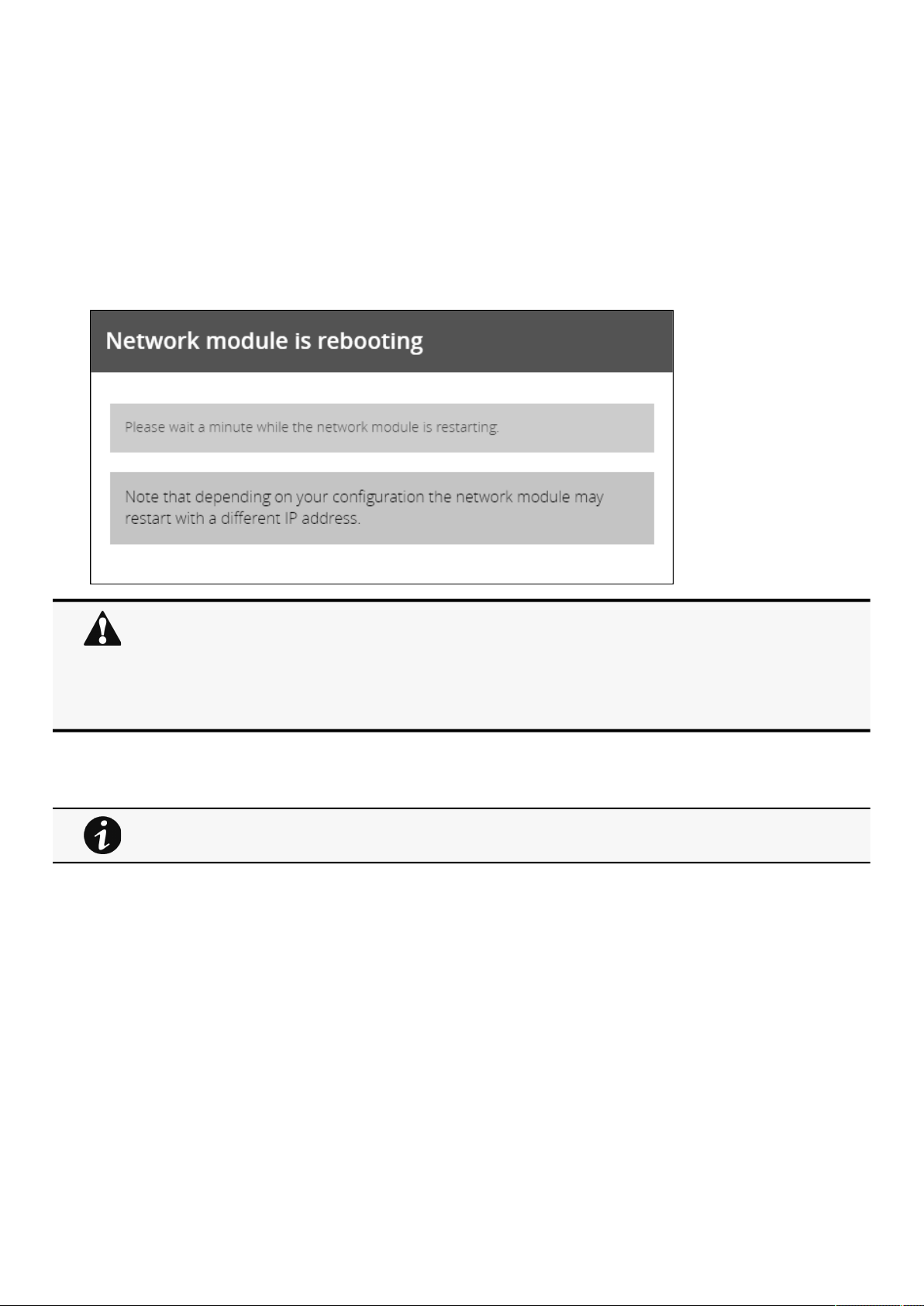
Card
Contextual Help – 77
•
•
•
2. Click+Upload.
3. Select the firmware package by navigating to the folder where you saved the downloaded firmware.
4. ClickUpload. The upload can take up to 5 minutes.
The firmware that was inactive will be erased by this operation.
When an upgrade is in progress, the upload button is disabled, and the progress elements appear below the table
with the following steps:
Transferring > Verifying package > Flashing > Configuring system > Rebooting
A confirmation message displays when the firmware upload is successful, and the UPS Network Module automatically restarts.
2.8.4.2 Sanitization
Sanitization removes all the data; the Network Module will come back to factory default settings.
To sanitize the Network Module:
Click
Sanitize.
A confirmation message displays, click Sanitize to confirm.
Do not close the web browser or interrupt the operation.
Depending on your network configuration, the Network Module may restart with a different IP address.
Refresh the browser after the Network module reboot time to get access to the login page.
Press F5 or CTRL+F5 to empty the browser to get all the new features displayed on the Web user
interface.
Communication Lost and Communication recovered may appear in the Alarm section.
For details on default settings, see the
Information>>>Default settings parameters
section .
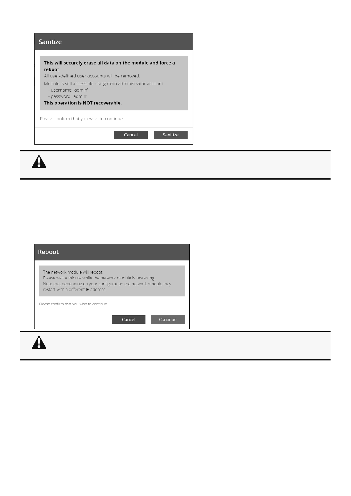
Card
Contextual Help – 78
•
•
2.8.4.3 Reboot
Reboot means restarting the network module operating system.
To reboot the Network Module:
Click
Reboot.
A confirmation message displays, clickContinueto confirm, the reboot time will take approximately less than 2min.
2.8.4.4 Maintenance
The maintenance report is for the service representative use to diagnose problems with the network module. It is not intended for the
user, which is why the file is protected by a password. None of the network module users or network information are extracted.
To download the maintenance report file:
Click
Download report.
A confirmation message displays,Maintenance report file successfully downloaded.
Depending on your network configuration, the Network Module may restart with a different IP address.
Only main administrator user will remain with default login and password.
Refresh the browser after the Network module reboot time to get access to the login page.
Depending on your network configuration, the Network Module may restart with a different IP address.
Refresh the browser after the Network module reboot time to get access to the login page.
Communication Lost and Communication recovered may appear in the Alarm section.
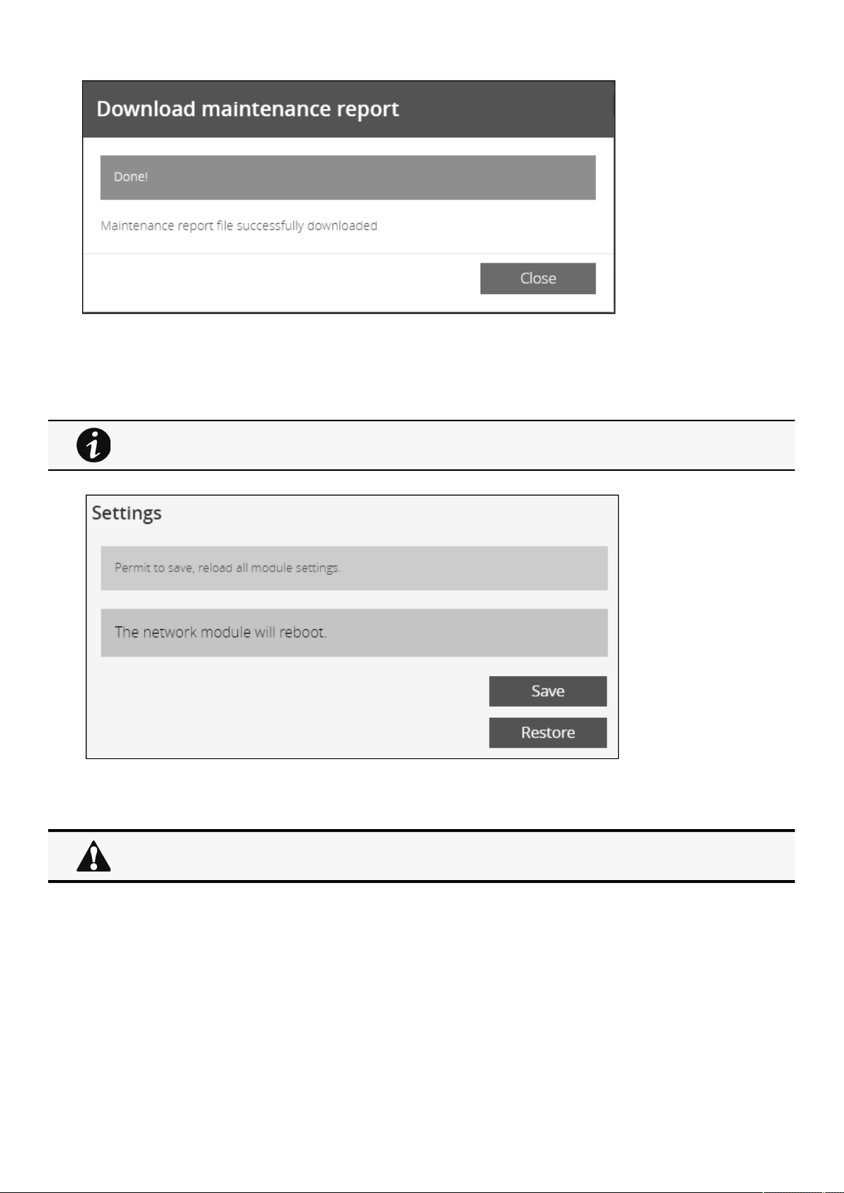
Card
Contextual Help – 79
2.8.4.5 Settings
Allow to save and restore the Network module settings.
2.8.4.5.1 Save
For more details, navigate to
Servicing the Network Management Module>>>Saving/Restoring/
Duplicating
Network module configuration settings.
Below settings are not saved:
Local users other than the main administratorSensor settings (commissioning, alarm configuration)
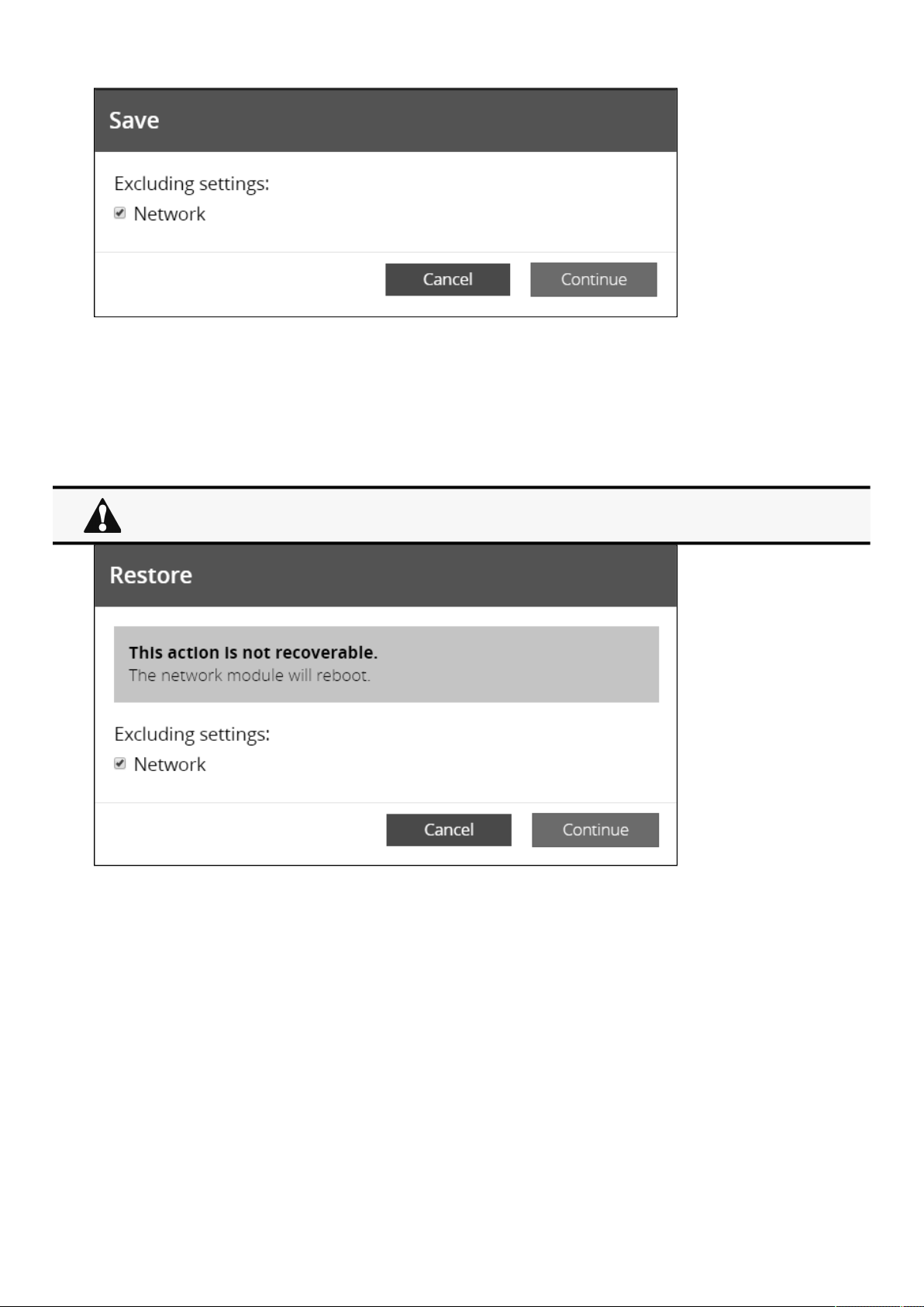
Card
Contextual Help – 80
•
•
•
•
•
•
•
•
•
•
To save the Network module settings:
Click onSave
Select to include the Network settings if needed.
A passphrase need to be entered twice to cypherthe sensitive data.
Click onContinue
2.8.4.5.2 Restore
To restore the Network module settings:
Click onRestore
Select to include the Network settings if needed.
Click onContinue
Select the JSON file
If sensitive data are detected, enter the passphrase used when the file was saved.
Click again onContinueto confirm
Restoring settings may result in the Network module reboot.
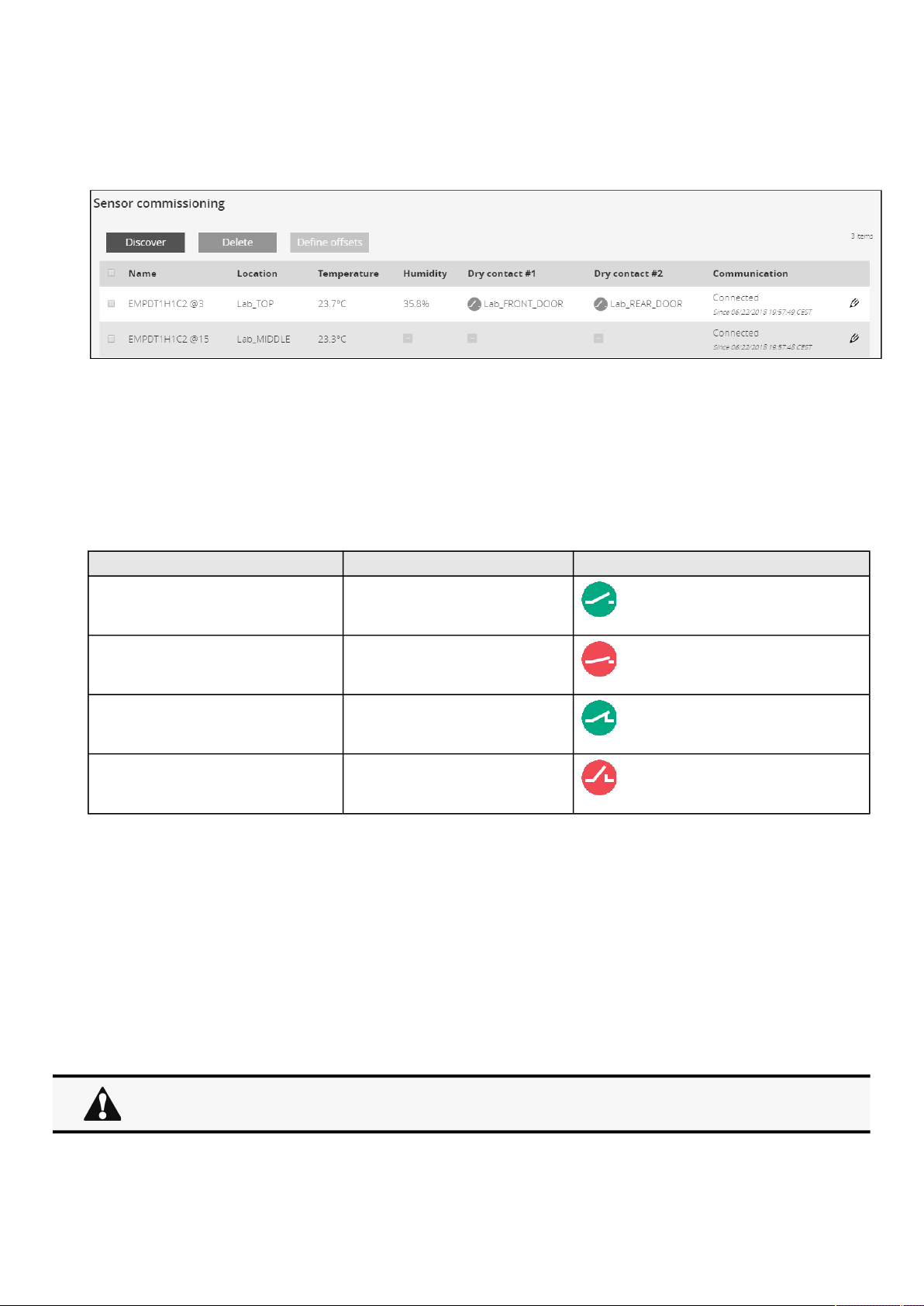
Card
Contextual Help – 81
•
•
•
•
•
•
•
2.8.5 Commissioning (sensors)
2.8.5.1 Sensors commissioning table
The table displays the sensors commissioning information and includes the following details.
Name
Location – location-position-elevation
Temperature
Humidity
Dry contact #1 – Status and name
Dry contact #2 –Status and name
Polarity setCurrent stateDry contact status
Normally openopen
Normally openclosed
Normally closedclosed
Normally closedopen
Communication –Connected/Lost with dates
2.8.5.2 Actions
2.8.5.2.1 Discover
At first the table is empty, press the
Discoverbutton to launch the sensor discovery process.
If sensors are discovered, the table is populated accordingly
2.8.5.2.2 Delete
Select a sensor and press the
Deletebutton to delete the sensor.
When a sensor is deleted, all the commissioning information are deleted.
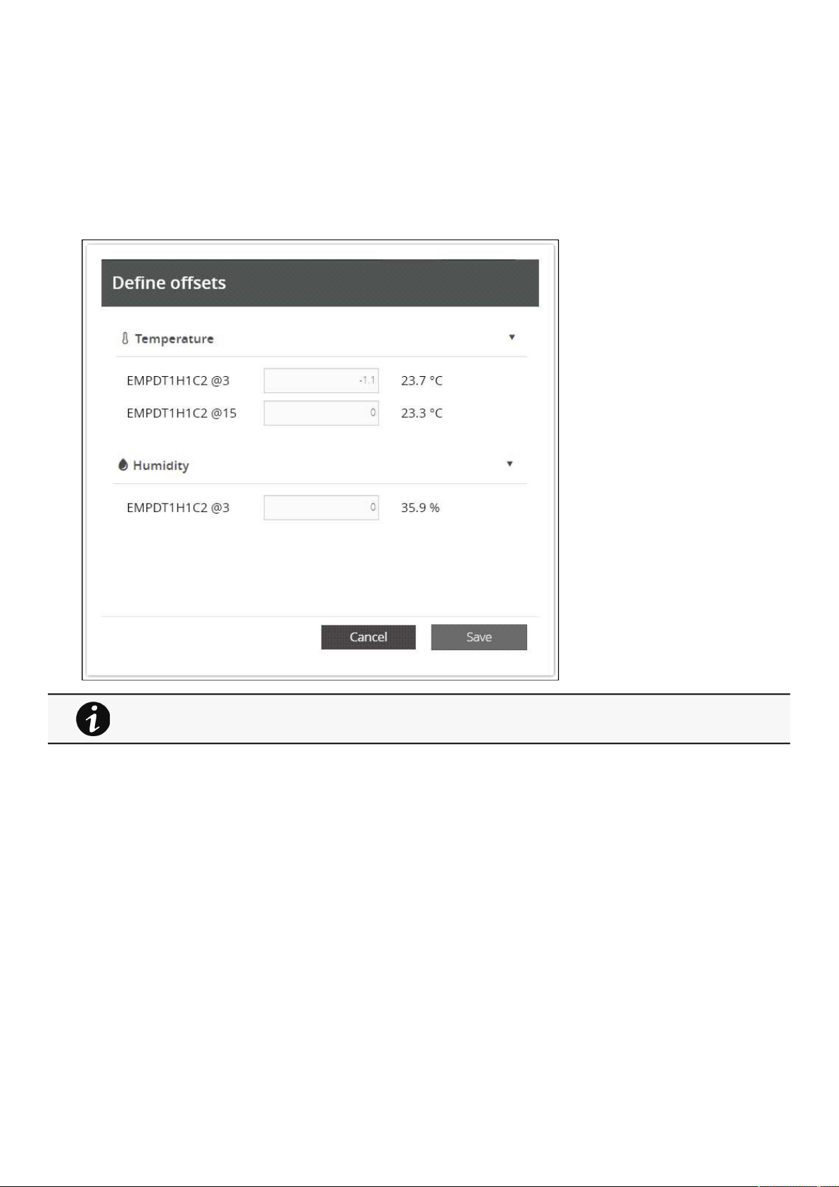
Card
Contextual Help – 82
2.8.5.2.3 Define offsets
Select the sensors.
Press the
Define offsetbutton to adjust the temperature and humidity offsets of the selected sensors.
Extend the temperature or humidity section.
Set the offsets in the cell, temperatures and humidity will be updated accordingly.
Press the Save button when done.
Deactivated humidity or temperatures are not displayed.
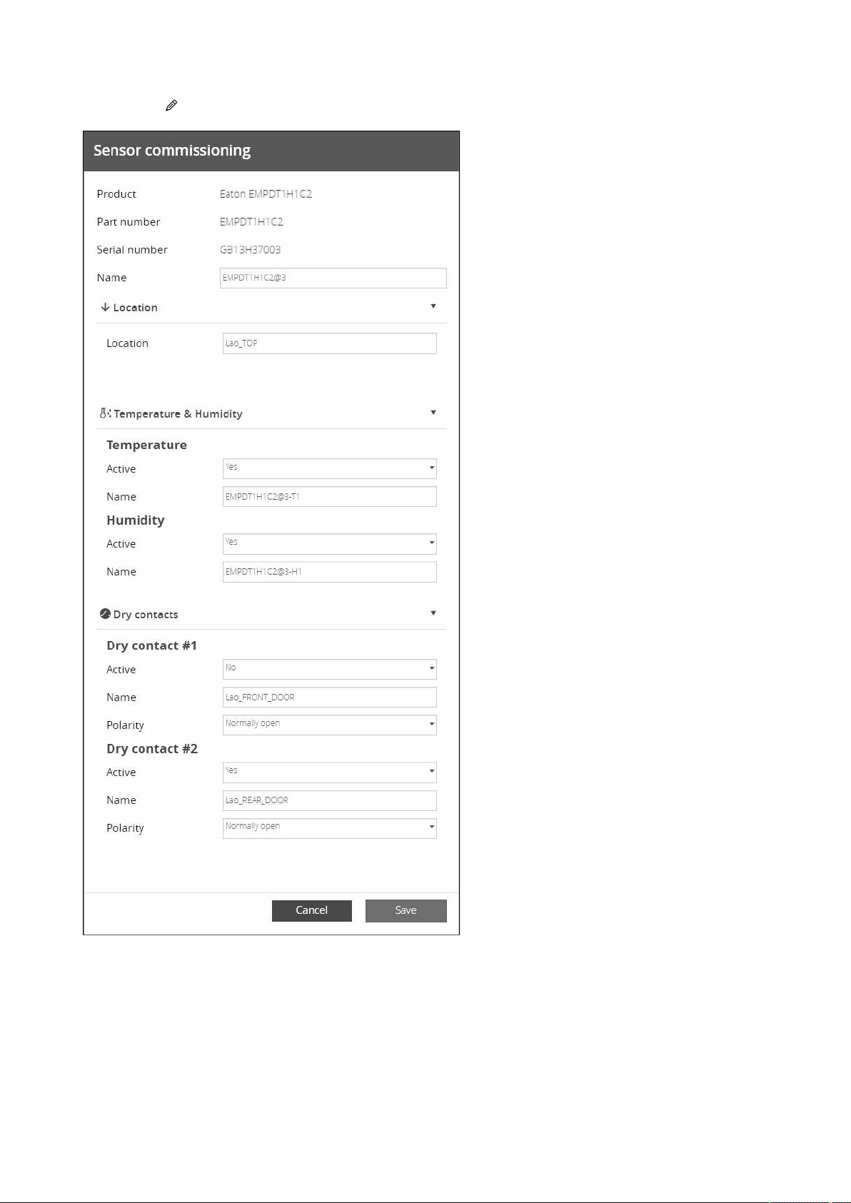
Card
Contextual Help – 83
•
•
•
•
•
•
•
2.8.5.2.4 Edit
Press the pen logo to edit sensor communication information and access to the following information and settings:
Product reference
Part number
Serial number
Name
Location
Temperature and humidity – Active (Yes, No)
Dry contacts –Active (Yes, No)/Name/Polarity (Normally open, Normally closed)
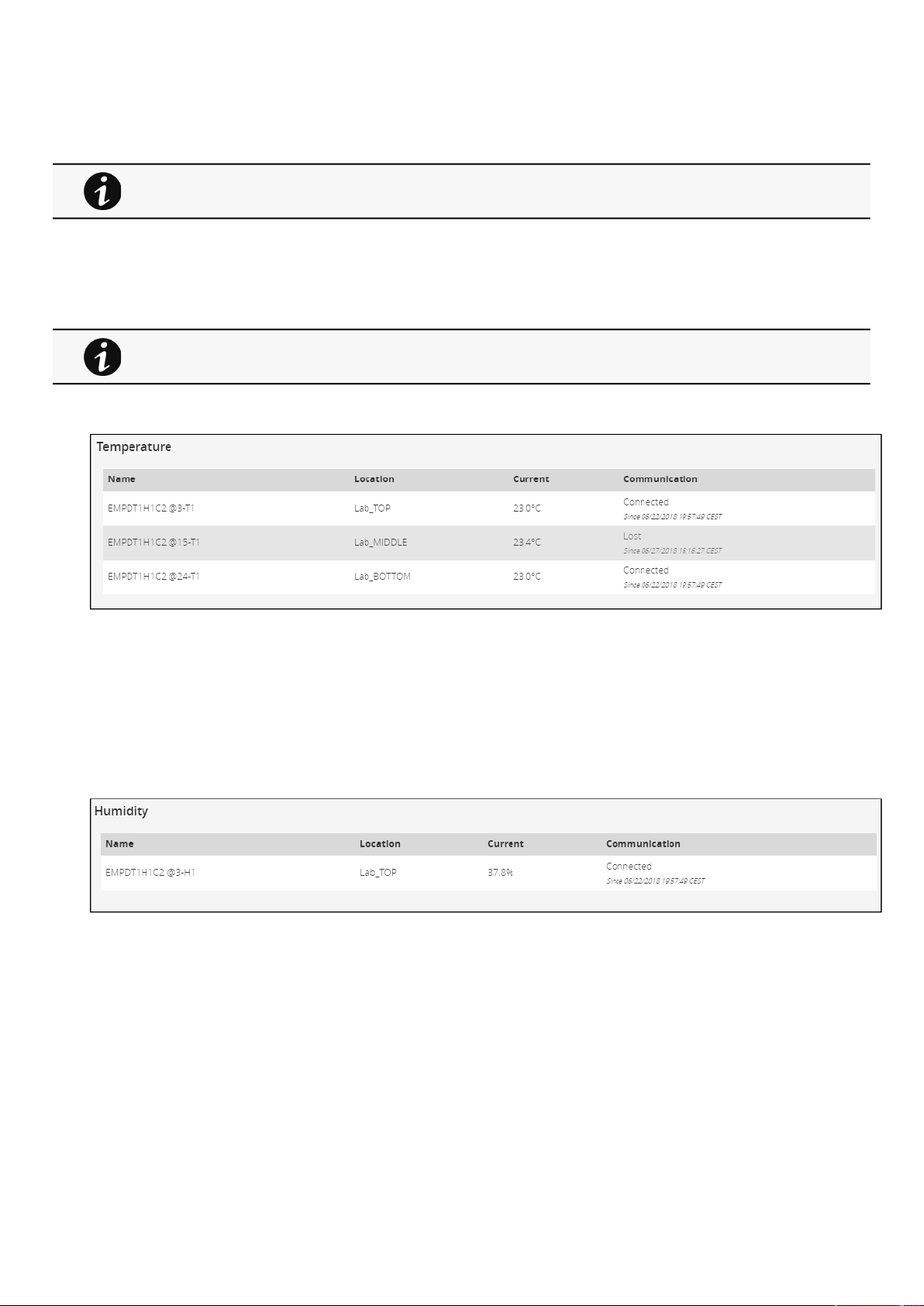
Sensors
Contextual Help – 84
•
•
•
•
•
•
•
•
PressSaveafter modifications.
2.8.5.3 Note:
2.9 Sensors
2.9.1 Status (sensors)
2.9.1.1 Temperature table
The table shows the following information for each sensor:
Name
Location
Current temperature
Communication–Connected/Lost with dates
2.9.1.2 Humidity table
The table shows the following information for each sensor:
Name
Location
Current humidity
Communication
–Connected/Lost with dates
If the UPS provides temperature compensated battery charging option, see the
Servicing the
EMP>>>Using the EMP for temperature compensated battery charging
section
Humidities, temperatures or dry contacts deactivated during commissioning are not displayed.
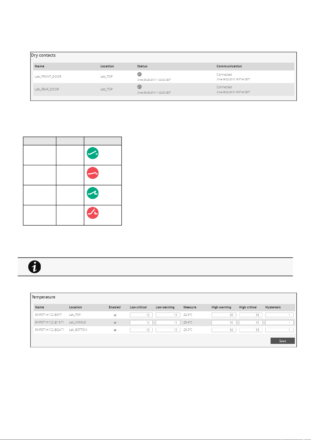
Sensors
Contextual Help – 85
•
•
•
•
•
•
•
•
•
•
2.9.1.3 Dry contacts table
The table shows the following information for dry contacts:
Name
Location
Status with date:
Polarity setCurrent stateDry contact status
Normally openopen
Normally openclosed
Normally closedclosed
Normally closedopen
Communication
–Connected/Lost with dates
2.9.2 Alarm configuration (sensors)
2.9.2.1 Temperature
The table shows the following information and settings for each sensor:
Name
Enabled– yes/no
Low critical threshold– xx°C or xx°F
Low warning threshold– xx°C or xx°F
Current temperature
High warning threshold– xx°C or xx°F
Humidity, temperatures or dry contacts deactivated during commissioning are not displayed.
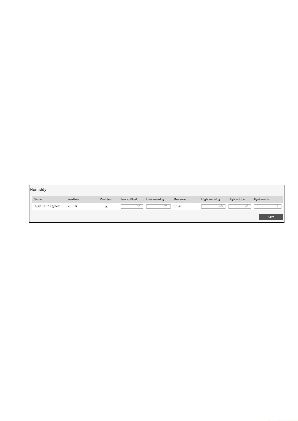
Sensors
Contextual Help – 86
•
•
•
•
•
•
•
•
•
•
High critical threshold– xx°C or xx°F
Hysteresis– x°C or x°F
2.9.2.1.1 Actions
a Set Enabled
Select and directly change the setting in the tableand then
Save.
When disabled, no alarm will be sent.
b Set alarm threshold
Select and directly change the setting in the tableand then
Save.
When a warning threshold is reached, an alarm will be sent with a warning level.
When a critical threshold is reached, an alarm will be sent with a critical level.
c Set Hysteresis
Select and directly change the setting in the tableand then
Save.
The hysteresis is the difference between the value where the alarm turns ON from turning OFF and the value where it turns OFF
from turning ON.
2.9.2.2 Humidity
The table shows the following information and settings for each sensor:
Name
Enabled
–yes/no
Low critical threshold– xx%
Low warning threshold– xx%
Current humidity
High warning threshold– xx%
High critical threshold– xx%
Hysteresis– x%
2.9.2.2.1 Actions
a Set Enabled
Select and directly change the setting in the tableand then
Save.
When disabled, no alarm will be sent.
b Set alarm threshold
Select and directly change the setting in the tableand then
Save.
When a warning threshold is reached, an alarm will be sent with a warning level.
When a critical threshold is reached, an alarm will be sent with a critical level.
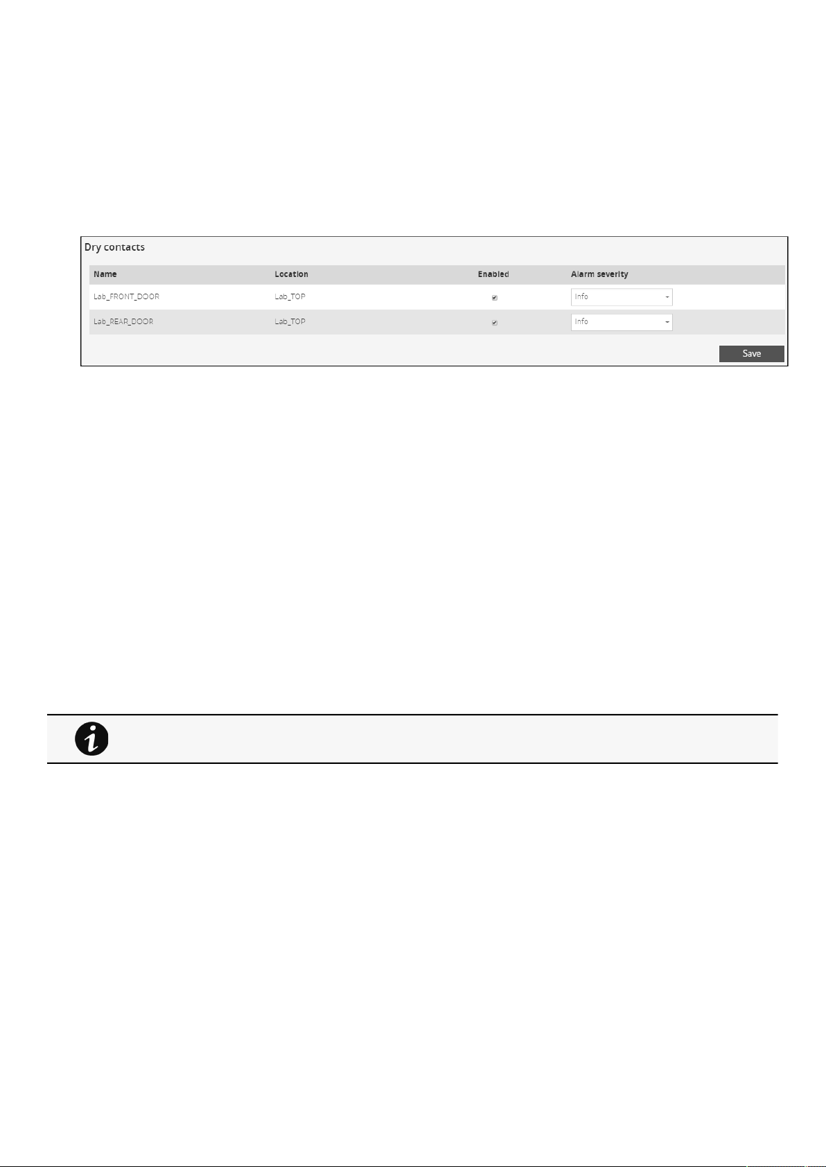
Sensors
Contextual Help – 87
•
•
•
c Set Hysteresis
Select and directly change the setting in the tableand then
Save.
The hysteresis is the difference between the value where the alarm turns ON from turning OFF and the value where it turns OFF
from turning ON.
2.9.2.3 Dry contacts
The table shows the following settings for each dry contact:
Name
Enabled
–yes/no
Alarm severity – Info/Warning/Critical
2.9.2.3.1 Actions
a Set Enabled
Select and directly change the setting in the tableand then
Save.
When disabled, no alarm will be sent.
b Set alarm severity
Select and directly change the setting in the tableand then
Save.
Dry contacts alarm will be sent at the selected level.
2.9.2.4 Default settings parameters and limitations
2.9.3 Information (sensors)
Sensor information is an overviewof all the sensors information connected to the Network Module.
For details on default parameters and limitations, see the
Information>>>Default settings
parameters
section
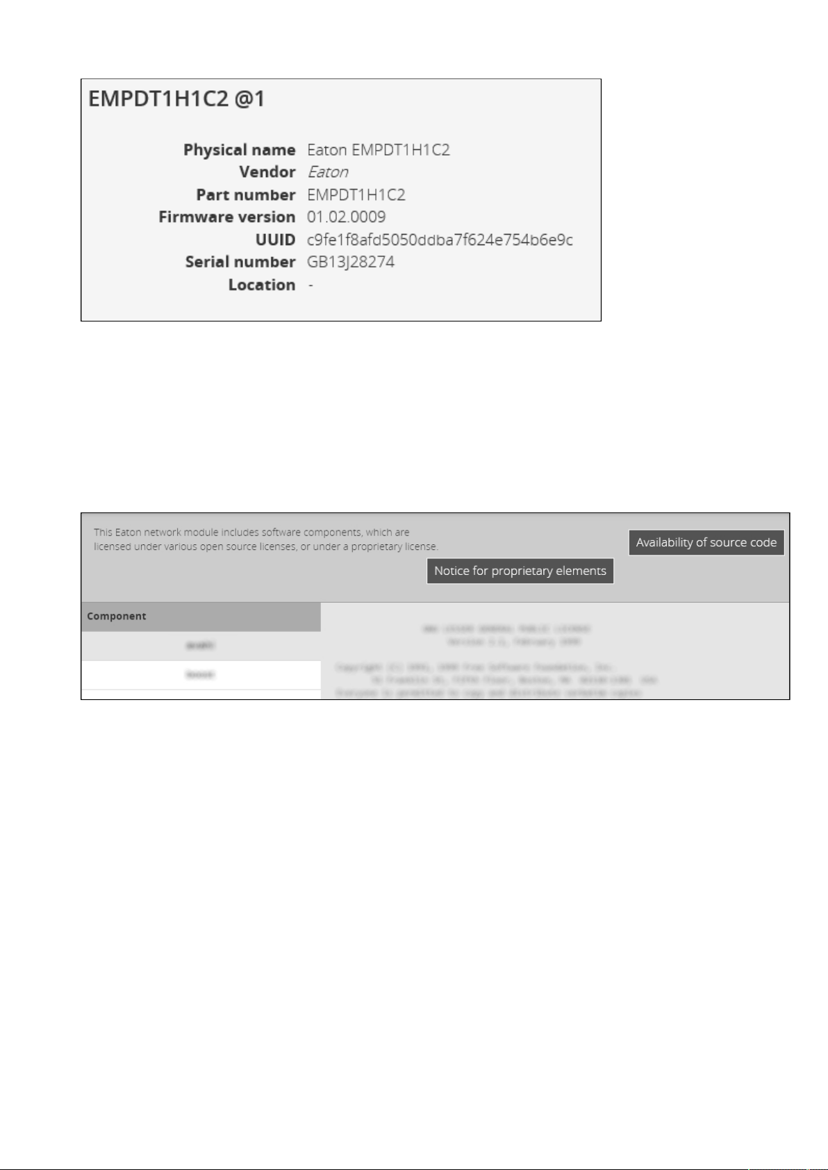
Legal information (footer)
Contextual Help – 88
•
•
•
•
•
•
•
Physical name
Vendor
Part number
Firmware version
UUID
Serial number
Location
2.10 Legal information (footer)
This Network Module includes software components that are either licensed under various open source license, or under a
proprietary license.
2.10.1 Component list
All the open source components included in the Network Module are listed with their licenses.
2.10.2 Notice for our proprietary (i.e. non-Open source) elements
Provides notice for our proprietary (i.e. non-Open source) elements.
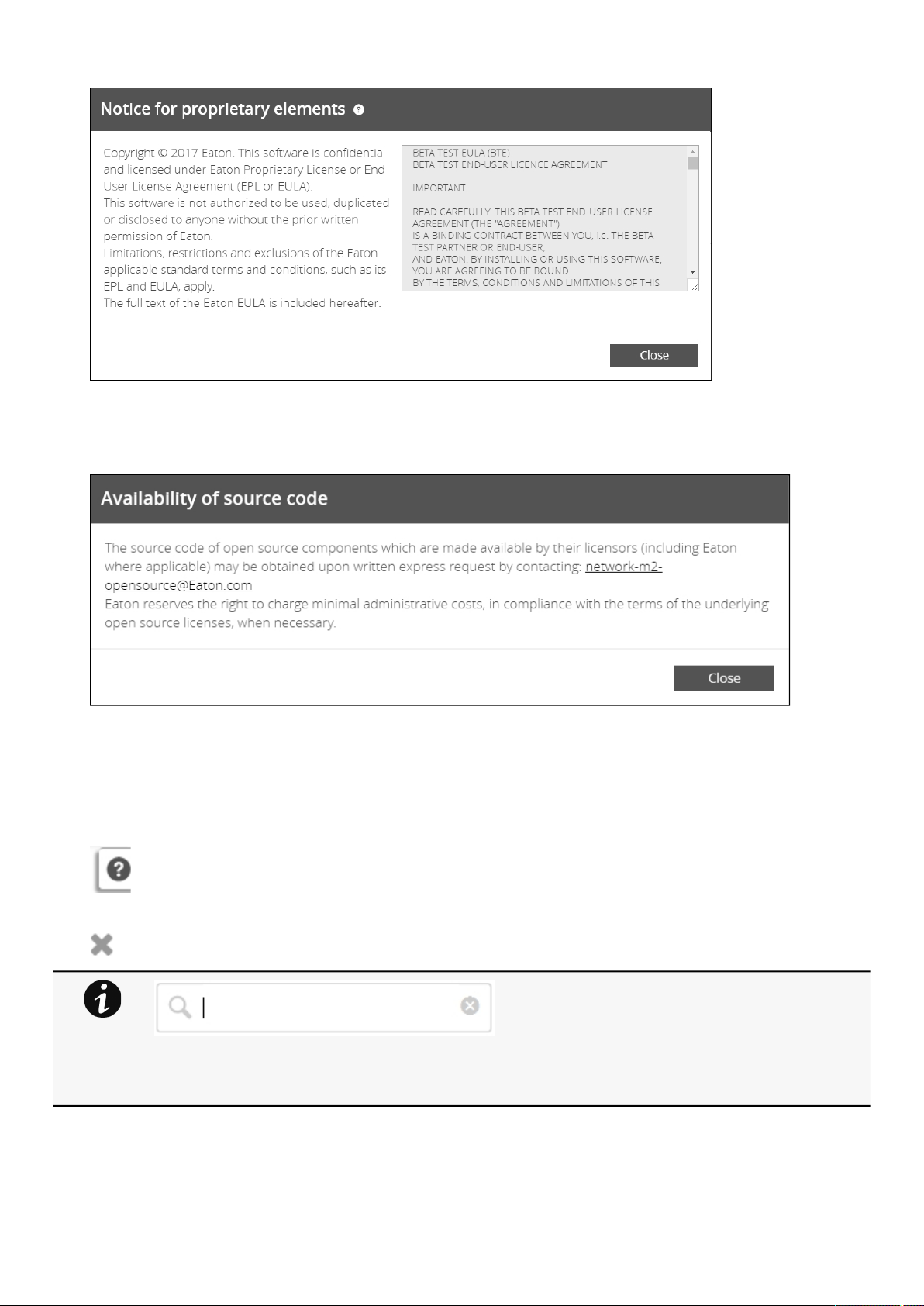
Contextual help and full documentation
Contextual Help – 89
2.10.3 Availability of source code
Provides the way to obtain the source code of open source components that are made available by their licensors.
2.11 Contextual help and full documentation
2.11.1 Access to contextual help
Press
?icon on the top right side of the page to access the contextual help.
Contextual help can be closed by pressing the
Xicon on the top right of the page.
2.11.2 Access to full documentation
Press
?icon on the top right side of the page to access the contextual help.
Search feature is indexed, but when inside the contextual help section it won't search in the full
documentation.
To get better results when searching, search inside the full documentation.

Contextual help and full documentation
Contextual Help – 90
•
•
•
•
•
In the contextual help section, press the Full documentationbutton on the top right to access the full documentation in a new
window.
You can then navigate into below sections:
Contextual help
Servicing the Network Management Module
Securing the Network Management Module
Information
Troubleshooting
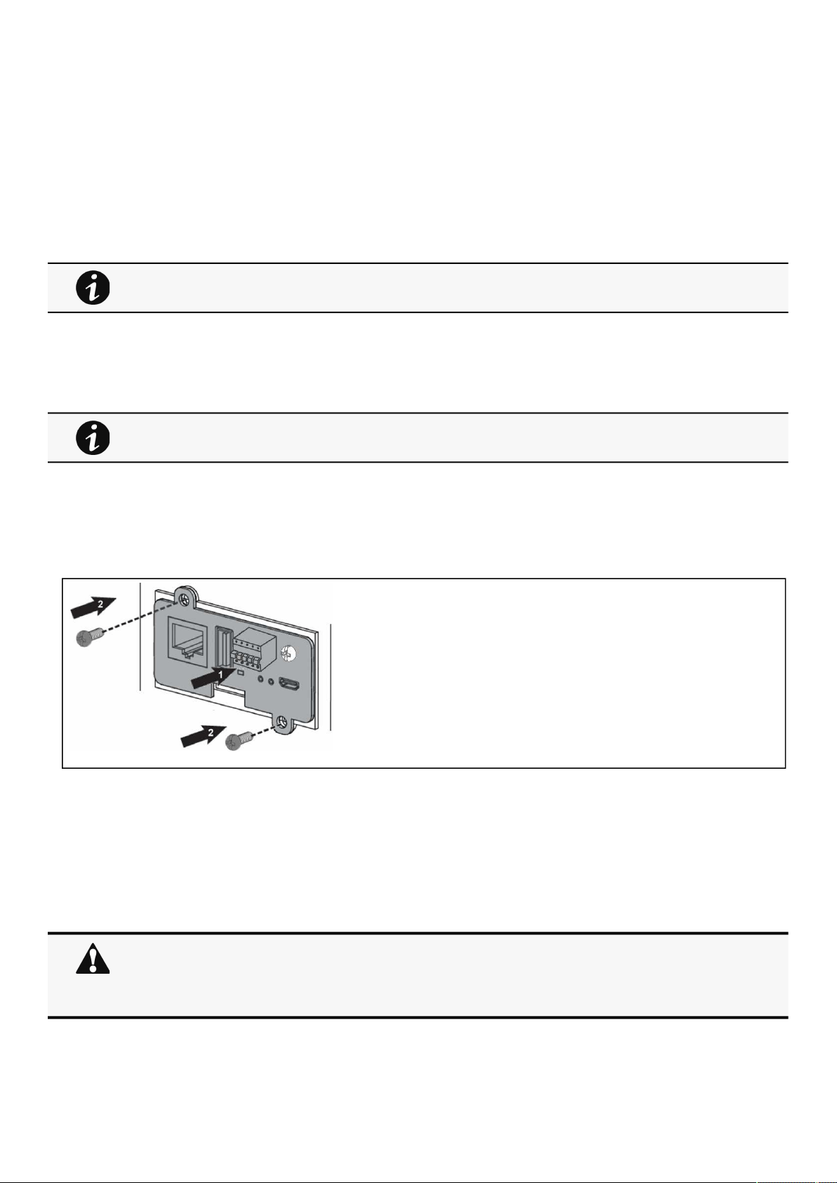
Unpacking the Network module
Servicing the Network Management Module – 91
•
•
•
•
3 Servicing the Network Management Module
3.1 Unpacking the Network module
The network module will include the following:
RS-485 wiring terminal (
For INDGW-M2 only)
3.2 Installing the Network Module
3.2.1 Mounting the Network Module
The Network Module is hot-swappable. Inserting and/or extracting the Network Module from the communication slot of theproduct
has no effect on the output.
Remove the two screws securing the option slot cover plate and store the plate for possible future use.
Install theNetwork Module along the alignment channels in the option slot.
Secure the Network Module using the two screws.
If theproduct is powered up, you can verify that the Network Module is seated properly and communicating with
theproduct by checking that the Status ON LEDflashes green after 2 minutes.
3.2.2 Wiring the RS-485 Modbus RTU terminal
The Modbus Network Module provides an easy path for integrating anEatonUPS into an RS-485 Modbus network and also
provides isolation of the communication between the UPS and the RS-485 Modbus network.
Use the terminal strip on the ModbusNetwork Module to wire into a two-wire network.
Packing materials must be disposed of in compliance with all local regulations concerning waste.
Recycling symbols are printed on the packing materials to facilitate sorting.
It is not necessary to power down theUPS before installing the Network Module. Required tools: No. 2
Phillips screwdriver.
If the Modbus Network Module is the last device installed in the network chain or the length of the
network cable is excessive, termination needs to be enabled.
For details on termination, see the
Wiring the RS-485 Modbus RTU terminal>>>Configuring the
termination
section.
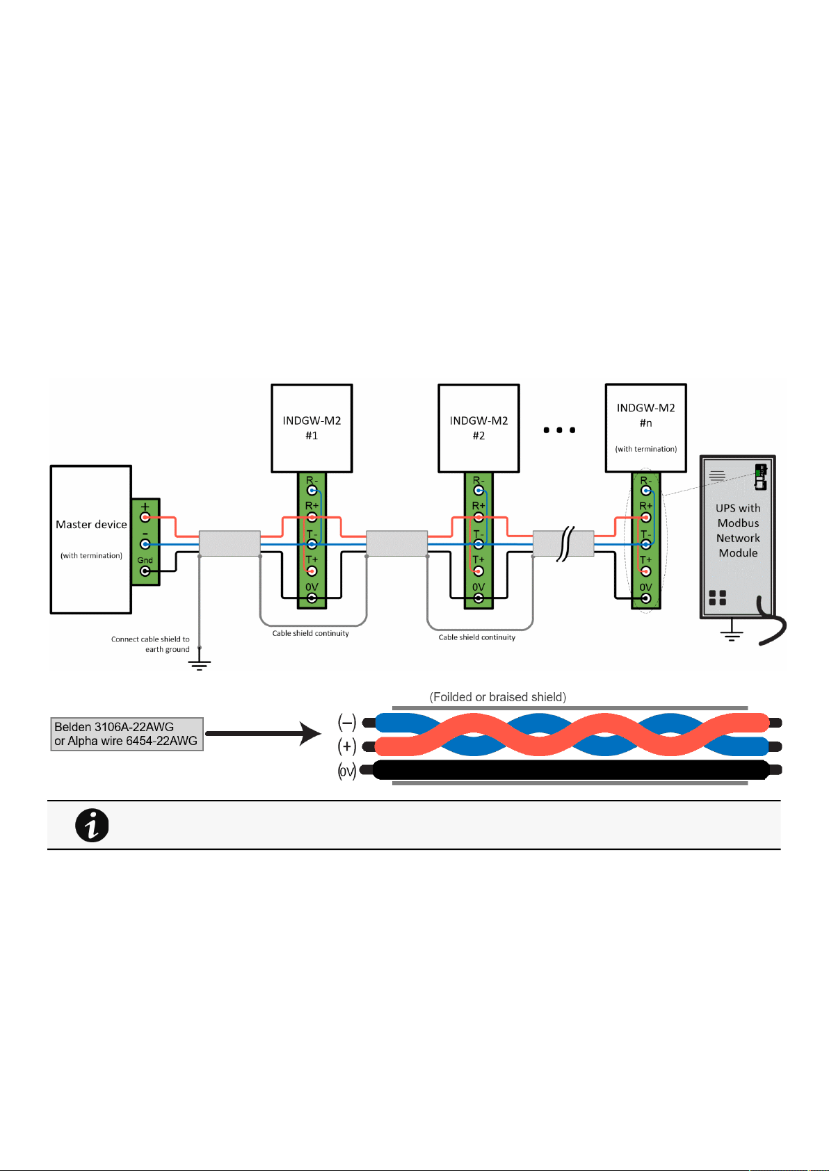
Installing the Network Module
Servicing the Network Management Module – 92
•
•
•
3.2.2.1 Modbus Common/GND (0V pin on terminal block)connection
The Network Module is an isolated device, if all the other devices on the network are isolated, common/GND (0V pin on terminal
block) should be connected between devices to limit common mode voltage.
Common/GND (0V pin on terminal block) should not be connected to any other devices that is not isolatedto avoid ground loops.
3.2.2.2 Cable shield connection (foiled or braised)
The cable shield should be continuous on the entire length of the bus and should be connected to ground (earth) at only one point
to limit the flow of ground-loop currents in the shield caused by ground potential differences.
3.2.2.3 Two-wire networks
Interconnect R- with T- and R+ with T+ onthe Modbus Network Moduleterminal strip.
Connect the RS-485 network signal
+ to the R+ or T+ on the Modbus Network Moduleterminal strip.
Connect the RS-485 network signal – to the R- or T- on the ModbusNetwork Moduleterminal strip.
3.2.2.4 Four-wire networks
All four RS-485 network signals including T-, T+, R–, and R+ must be connected respectively to the terminal strip R-, R+, T-, T+.
Belden 3106A-22AWG or equivalent cabling (a 1.5 twisted-pair shielded 120Ω cable with ground) is
recommended.
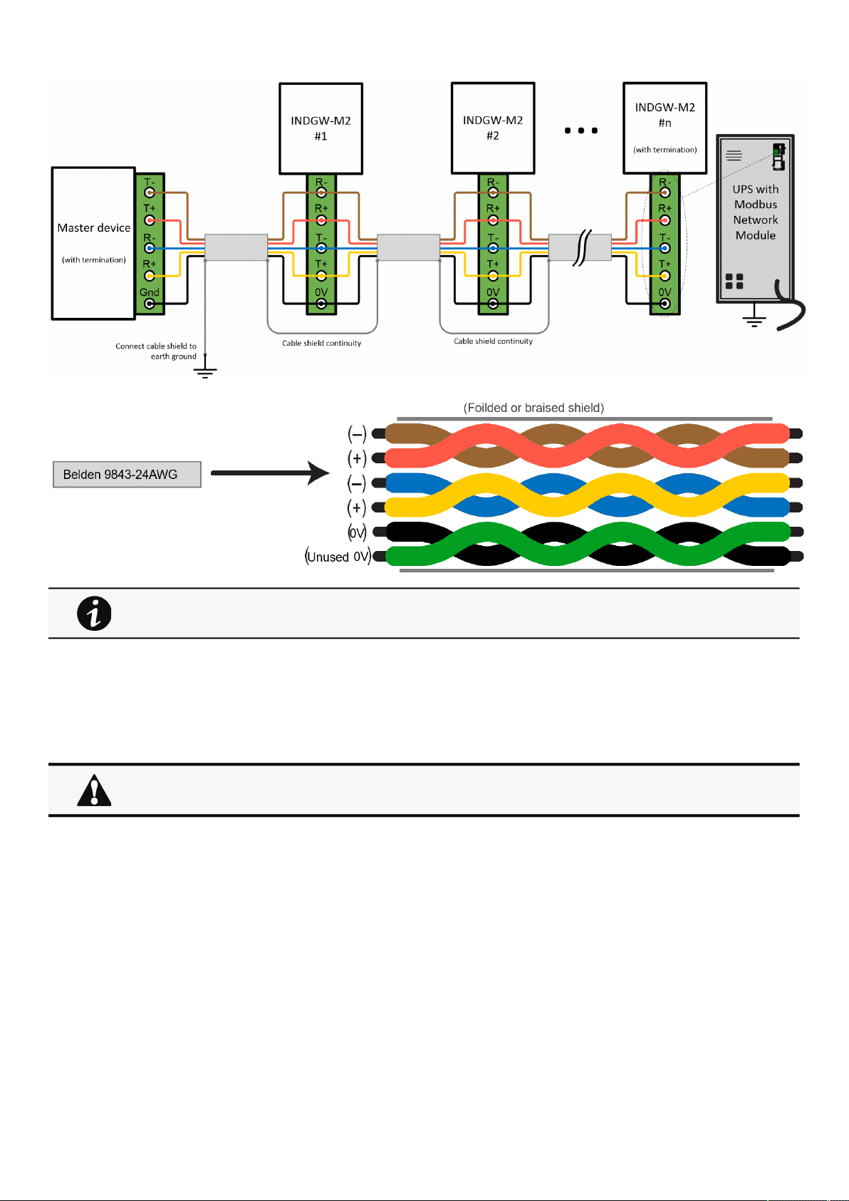
Installing the Network Module
Servicing the Network Management Module – 93
1.
3.2.2.5 Configuring the termination
If the Modbus Card is the last device installed in the network chain or the length of the network cable is excessive, termination
needs to be enabled.
Termination is used to match impedance of a node to the impedance of the transmission line being used. When impedances are
mismatched, the transmitted signal is not completely absorbed by the load and a portion is reflected into the transmission line.
To enable the on-board termination resistor (120Ω):
Locate the termination switch that is located on the top of the Modbus Network Module.
Belden 9843-24AWG or equivalent cabling (3 twisted-pair shielded 120Ω cable with ground) is
recommended.
No more than two termination points should be used in the RS-485 network.
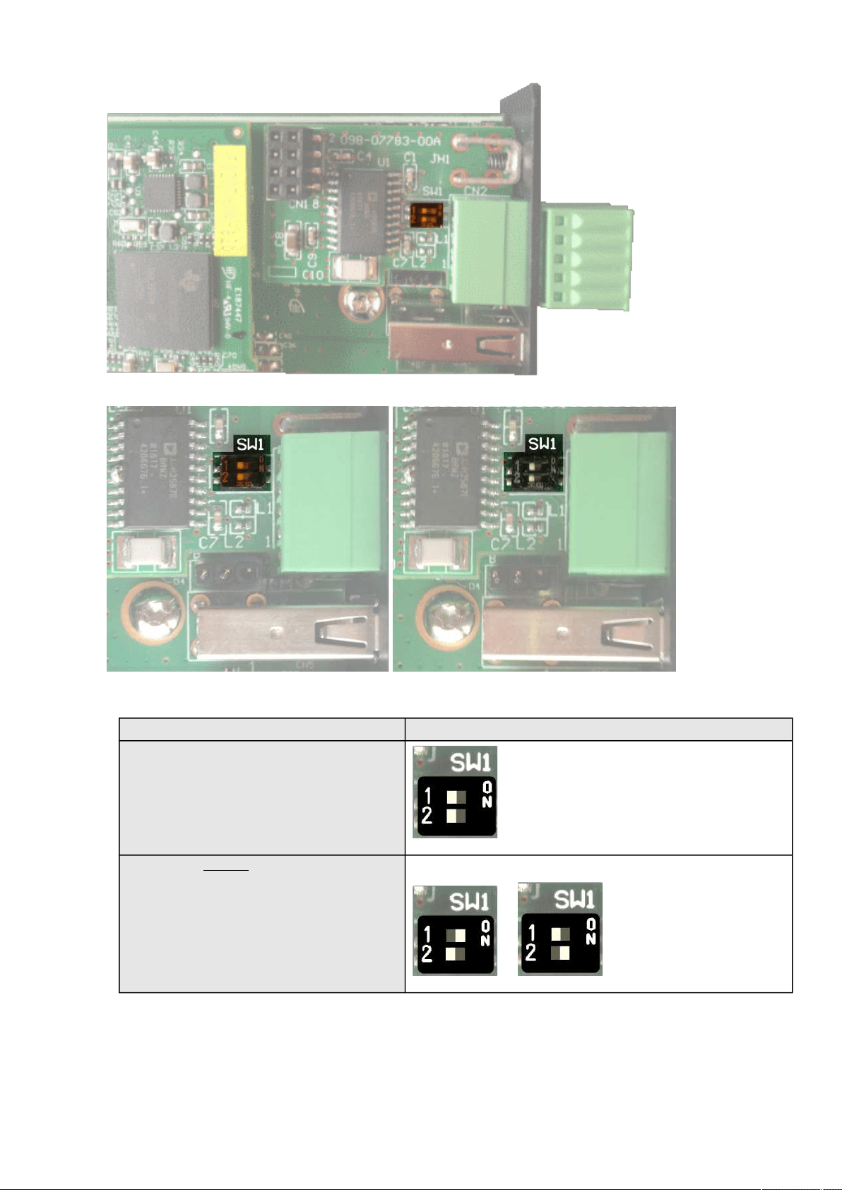
Installing the Network Module
Servicing the Network Management Module – 94
2.
3.
Peel off the protection:
Change the position of the termination switch according to your needs:
Switch position
No termination (default)
Termination for two-wire networksOne of the two position below can be used:
or
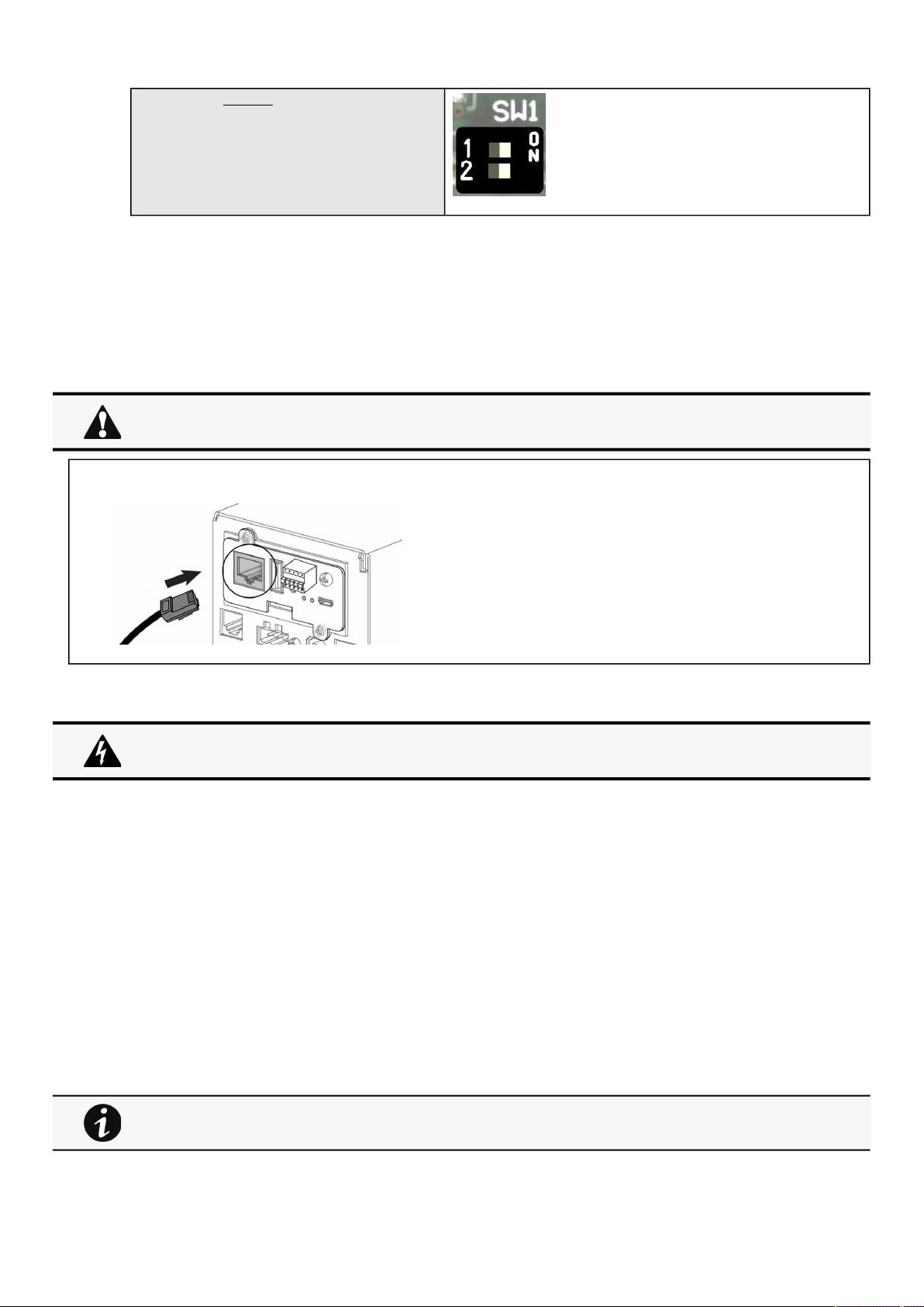
Accessing the Network Module
Servicing the Network Management Module – 95
1.
2.
3.
4.
5.
Termination for four-wire networks
3.3 Accessing the Network Module
3.3.1 Accessing the web interface through Network
3.3.1.1 Connecting the network cable
Connect a standard
gigabit compatible shielded ethernetcable (F/UTP or F/FTP)
between the network connector on theNetwork Module and a
network jack.
3.3.1.2 Accessing the web interface
On a network computer, launch a supported web browser. The browser window appears.
In the Address/Location field, enter: https://xxx.xxx.xxx.xxx,wherexxx.xxx.xxx.xxx
is the static IP address of the Network
Module.
The log in screen appears.
Enter the user name in the User Name field. The default user name is admin.
Enter the password in the Password field. The default password is admin.
The password must be changed at first login.
Click Sign In. The Network Module web interface appears.
3.3.2 Finding and setting the IP address
3.3.2.1 Your network is equipped with a BOOTP/DHCP server (default)
3.3.2.1.1 Read from the device LCD
If your device has an LCD, from the LCD’s menu, navigate to Identification>>>"COM card IPv4".
Security settings in the Network Module may be in their default states.
For maximum security, configure through a USB connection before connecting the network cable.
It is highly recommended that browser access to the Network Module is isolated from outside access
using a firewall or isolated network.
Note: some older UPS may not be able to display the IP address even if they have an LCD. Please
consult the UPS manual.
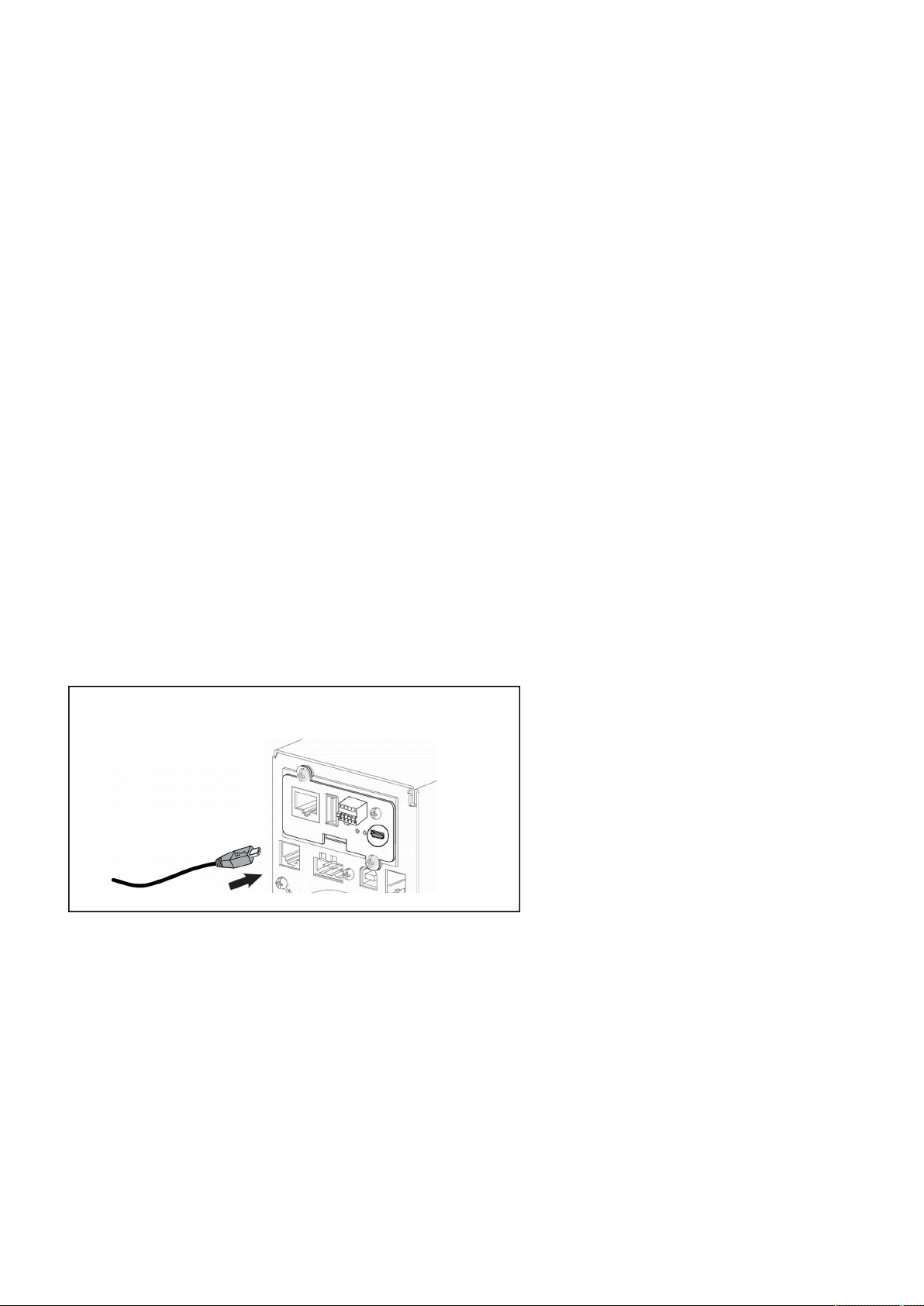
Accessing the Network Module
Servicing the Network Management Module – 96
•
•
•
•
•
•
•
•
Note the IP address of the card.
Go to the section: Accessing the web interface through Network.
3.3.2.1.2 With web browser throughthe configuration port
For example, if your device does not have an LCD, the IP address can be discovered by accessing the web interface through RNDIS
andbrowsing to Settings>Network.
To access the web interface through RNDIS, see the
Accessing the web interface through RNDISsection.
Navigate toSettings>>>Network>>>IPV4.
Read the IPv4 settings.
3.3.2.2 Your network is not equipped with a BOOTP/DHCP server
3.3.2.2.1 Define from the configuration port
The IP address can be defined by accessing the web interface through RNDIS.
To access web interface through RNDIS, see the
Accessing the web interface through RNDISsection.
Define the IP settings:
Navigate toSettings>>>Network>>>IPV4.
Select Manual (Static IP).
Input the following information: Address, Subnet Mask, Default Gateway
Save the changes.
3.3.3 Accessing the web interface through RNDIS
3.3.3.1 Connecting the configuration cable
1.Connect the Micro-B to USB cable to a USB connector on the host computer.
2. Connect the cable to the Settings connector on theNetwork Module.
This connection is used to access and configure the Network Module network settings locally through a RNDIS(Ethernet over USB
interface).
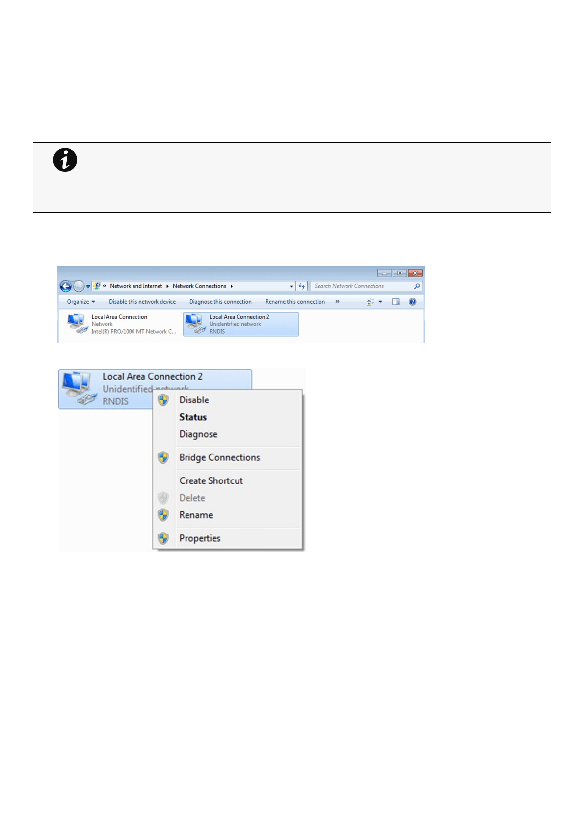
Accessing the Network Module
Servicing the Network Management Module – 97
3.3.3.2 Web interface access through RNDIS
3.3.3.2.1 Configuring the RNDIS
a Automatic configuration
b Manual configuration
1. In case
Windows® OS fails to find driver automatically, go to theWindows control panel>Network and sharing center>Local area
connection
2. Right click on the RNDIS local area connection and select Properties.
3.Select Internet Protocol Version 4 (TCP/IPv4)” and press the Properties button.
RNDIS driver is used to emulate a network connection from USB.
After the card is connected to the PC, Windows® OS will automatically search for the RNDIS driver.
On some computers, the OS can find the RNDIS driver then configuration is completed, and you can go
to Accessing the web interface.
On some others it may fail then proceed to manual configuration.
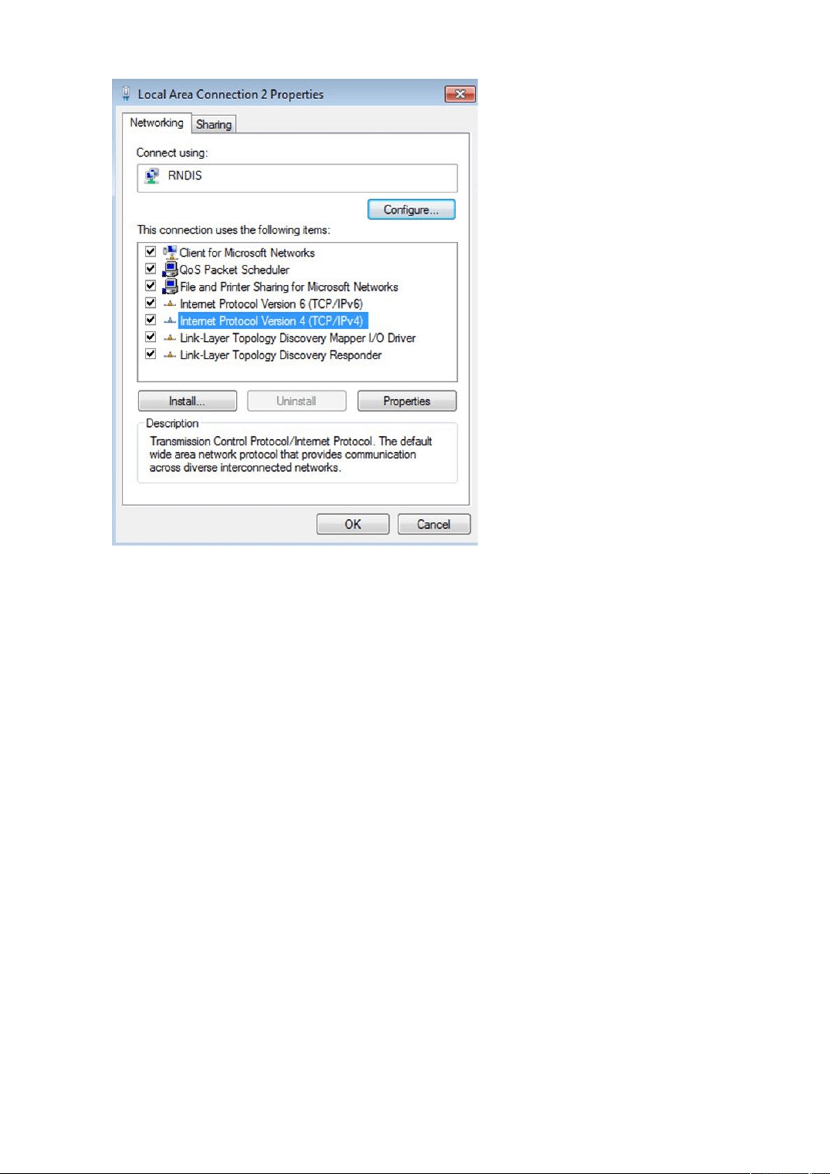
Accessing the Network Module
Servicing the Network Management Module – 98
4. Then enter the configuration as below and validate (IP = 169.254.0.150 and mask = 255.255.255.0), click OK, then click on Close.
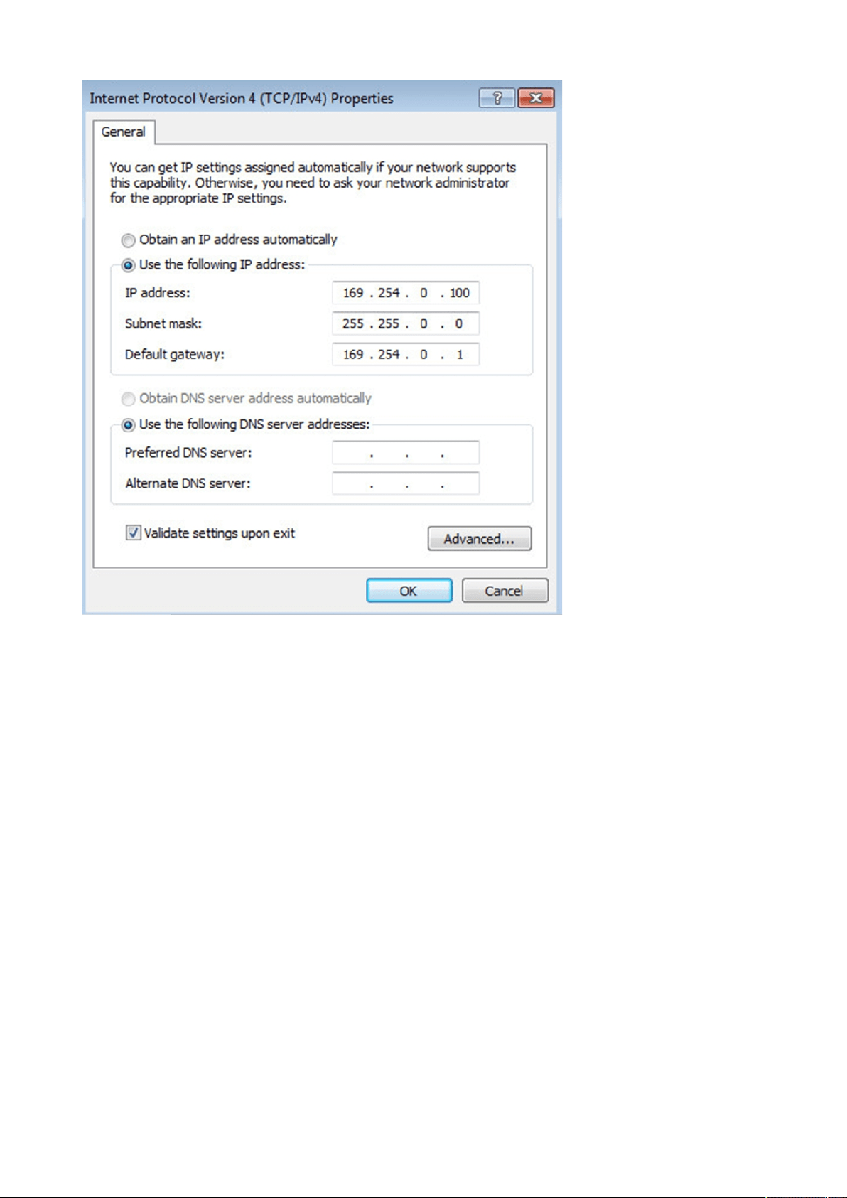
Accessing the Network Module
Servicing the Network Management Module – 99
3.3.3.2.2 Accessing the web interface
1.Be sure that the UPS is powered on.
2. On the host computer, download the rndis.7z file from the website www.eaton.com/downloads and extract it. For more
information, navigate to
Accessing to the latest Network Module firmware/driversection.
3. Launch setProxy.bat to add 169.254.* in proxy’s exceptions list, if needed. For manual configuration, navigate to Modifying the
Proxy exception list section in the full documentation.
4. Launch a supported browser, the browser window appears.
5. In the Address/Location field, enter: https://169.254.0.1, the static IP address of the Network Module for RNDIS. The log in
screen appears.
6. Enter the user name in the User Name field. The default user name isadmin.
7. Enter the password in the Password field. The default password isadmin.
8. ClickSign In. The Network Module local web interface appears.
3.3.4 Accessing the card through serial terminal emulation
3.3.4.1 Connecting the configuration cable
1.Connect the Micro-B to USB cable to a USB connector on the host computer.
2. Connect the cable to the Settings connector on theNetwork Module.
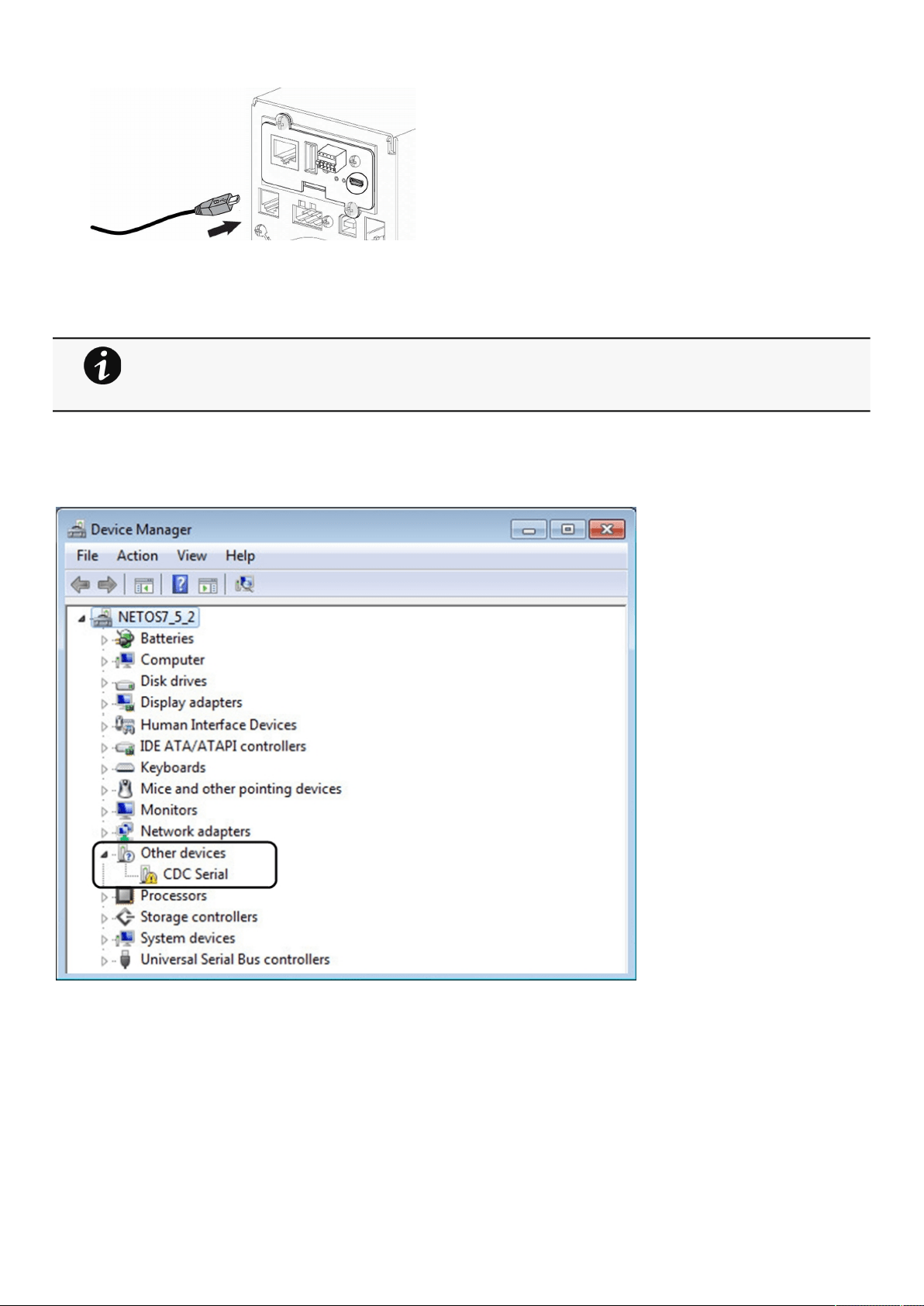
Accessing the Network Module
Servicing the Network Management Module – 100
This connection is used to access and configure the Network Module network settings locally through Serial (Serial over USB
interface).
3.3.4.2 Manual configuration of the serial connection
1.On the host computer,download therndis.7z file from the website www.eaton.com/downloads and extract it.
2. Plug the USB cable and go to
Windows® Device Manager.
3. Check the CDC Serial in the list, if it is with a yellow exclamation mark implying that driver has not been installed follow the steps
4-5-6-7 otherwise configuration is OK.
4. Right click on it and select Update Driver Software. When prompted to choose how to search for device driver software, choose
Browse my computer for driver software. Select Let me pick from a list of device drivers on my computer.
5. Select the folder where you have previously downloaded the driver file Click on Next.
6. A warning window will come up because the driver is not signed. Select Install this driver software anyway
7. The installation is successful when the COM port number is displayed for the Gadget Serial device in theWindows® Device
Manager.
Serial driver is used to emulate a serial connection from USB.
After the card is connected to the PC, manual configuration of the driver is needed for Windows® OS to
discover the serial connection.
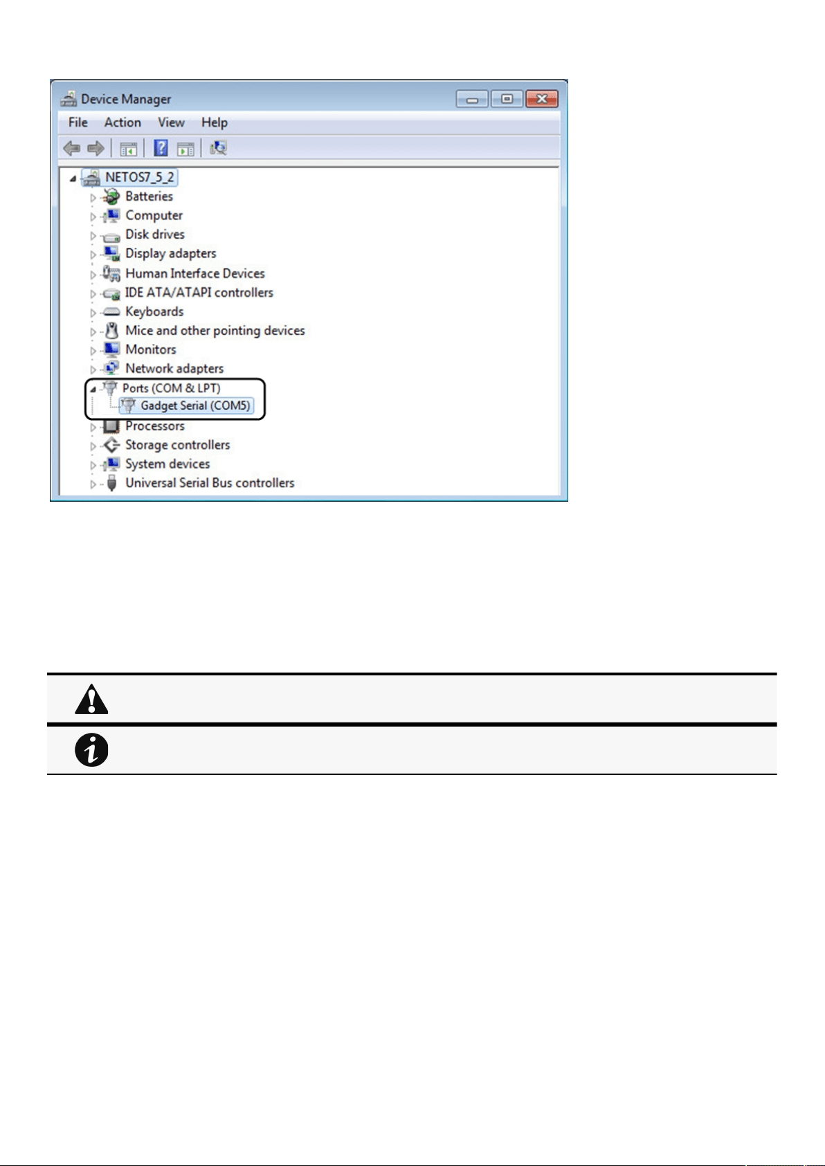
Accessing the Network Module
Servicing the Network Management Module – 101
•
•
•
•
3.3.4.3 Accessing the card through Serial
CLI can be accessed through:
SSH
Serial terminal emulation.
It is intended mainly for automated configuration of the network and time settings of the network card. It can also be used for
troubleshooting and remote reboot/reset of the network interface in case the web user interface is not accessible.
3.3.5 Modifying the Proxy exception list
To connect to the Network Module via a USB cable and your system uses a Proxy server to connect to the internet, the proxy
settings can reject the IP address 169.254.0.1.
The 169.254. * Sequence is used to set up communication with devices via a physical connection.
To activate this connection, exceptions will have to be made in the proxy settings.
Open Internet Explorer
Navigate to settings, Internet options;
Changing network parameters may cause the card to become unavailable remotely. If this happens it
can only be reconfigured locally through USB.
You can see this list of available commands by typing in the CLI:
?
You can see the help by typing in the CLI:
help
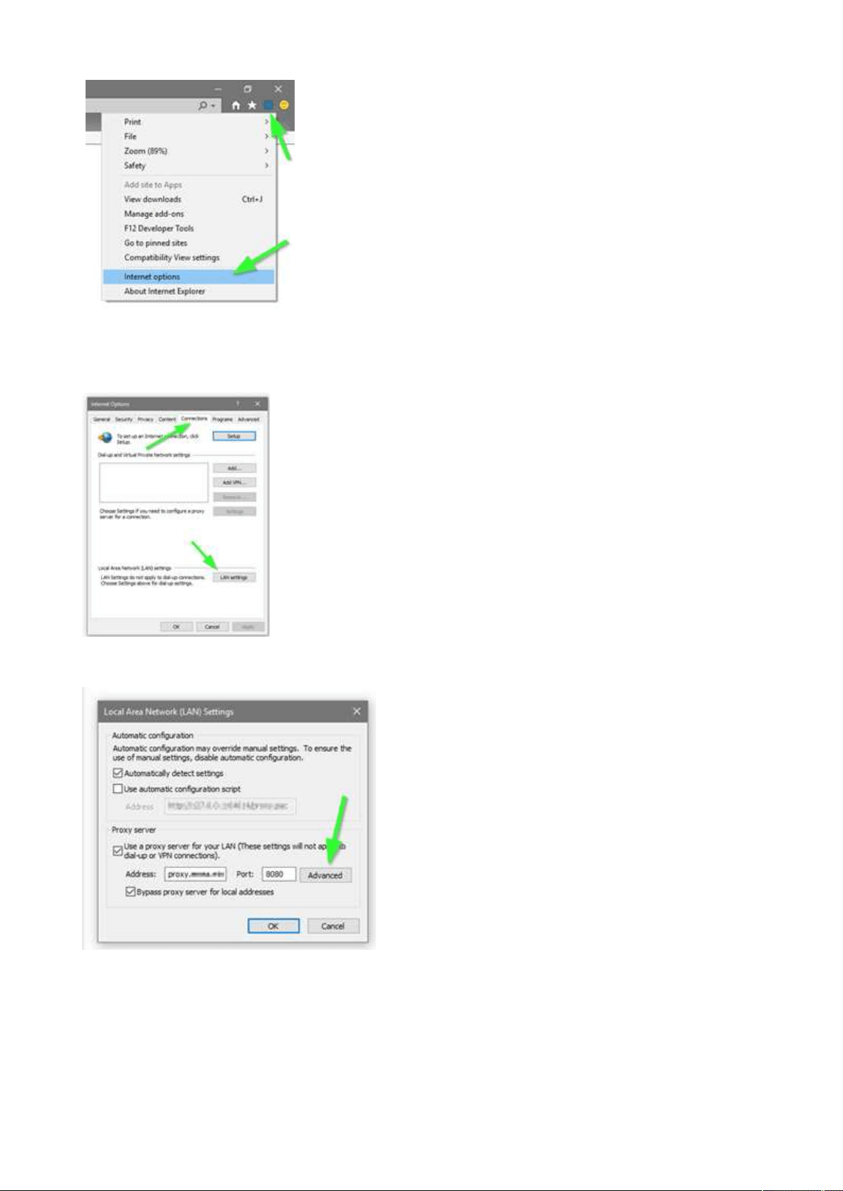
Accessing the Network Module
Servicing the Network Management Module – 102
•
•
•
•
Select the Connections tab
Press LAN Settings
Press ADVANCED
Add the address 169.254. *
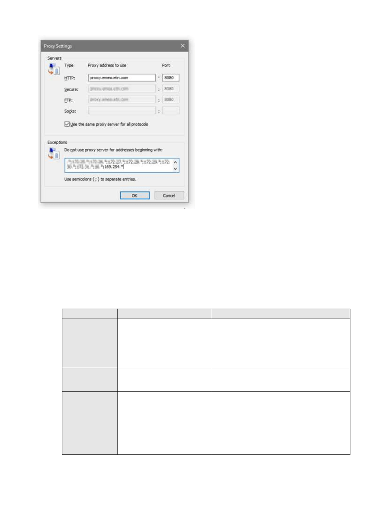
Configuring Modbus TCP and RTU
Servicing the Network Management Module – 103
•
•
•
•
•
Press OK.
Close Internet Explorer and re-open it.
Now you can access the address 169.254.0.1 with Internet Explorer and any other browser.
3.4 Configuring Modbus TCP and RTU
3.4.1 Configuring the communication parameters
Access the web interface through Network or RNDIS
Navigate to Settings>>>Modbus and set the communication parameters to the desired settings.
Default settingPossible parameters
Modbus RTUEnable — disabled
Baud rate (bps) — 19200
Parity — Even
Stop bits – 1
Enable — disable/enable
Baud rate (bps) —
1200/2400/4800/9600/19200/38400/57600/115200
Parity — None/Even/Odd
Stop bits – 1/2
Modbus TCPEnable — disabled
Port — 502
Enable — disable/enable
Port — x-xxx
Mapping configurationNo mappingName – 128 characters maximum
Map – Eaton ModbusMS compatible
Transport – RTU/TCP
Device ID – from 1 to 247
Access – None/Read only/Read/Write
Illegal read behavior –Return exception/Return zeros

Configuring Modbus TCP and RTU
Servicing the Network Management Module – 104
•
•
•
•
•
•
•
•
•
•
•
•
•
•
•
•
•
•
3.4.2 Available maps
Access the web interface through Network or RNDIS
Navigate to Settings>>>Modbus and press the
Supported MAPsbutton to download the MAPs.
3.4.2.1 Mapping table content
address (hex): register address in hexadecimal
address (1-base): register address in 1-base format
Type: Register/Discrete
Size in bytes
Number of modbus registers
Writable: True/False
Representation: Int16/Uint16/String/Boolean/...
Name
Description
Unit (Kelvin, A, V, W, VA,%, Hz, min, ...)
Status to 0: status when the discrete equal 0
Status to 1:status when the discrete equal 1
Available: True/False –Shows if the register is available on current UPS
Value: Shows current value of the register on current UPS
3.4.3 Modbus communication monitoring tool
Access the CLI through SSH or the Serial terminal emulation
Get available commands by typing
?
in the CLI
CLI commands can be used to retrieve Modbus communication statistics, navigate to
theInformation>>>CLI>>>modbus_statisticssection for more details.
3.4.4 Example of supported Modbus mapping
The following table is an example of the mapping information that can be retrieved in the Modbus settings by pressing the
Supported MAPs button.
For Modbus RTU configuration refer to the sectionContextual help>>>Settings>>>Modbus RTU.
For Modbus TCP configuration refer to the sectionContextual help>>>Settings>>>Modbus TCP.
File is generated in real time and will take into account the UPS capabilities and values at the time of the
generation.
Table in the downloaded file will show all possible registers, only the one showing Available equal to
True will be supported by your system.
The units used on Modbus map belong to the International System of Units, temperatures are
expressed in Kelvin for example.
For an example of supported Modbus mapping, navigate to Example of supported Modbus mapping.
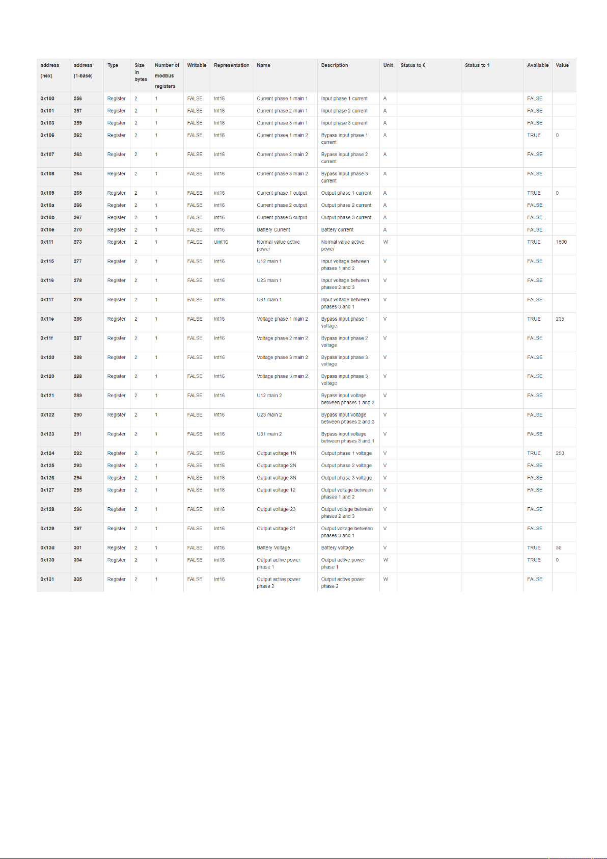
Configuring Modbus TCP and RTU
Servicing the Network Management Module – 105
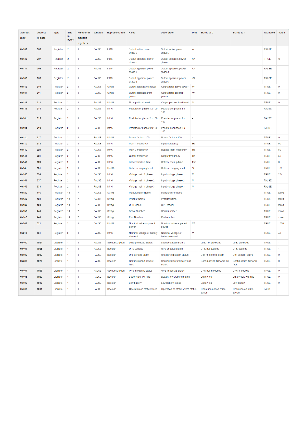
Configuring Modbus TCP and RTU
Servicing the Network Management Module – 106
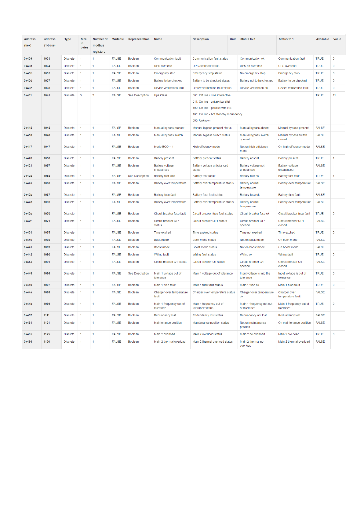
Configuring Modbus TCP and RTU
Servicing the Network Management Module – 107
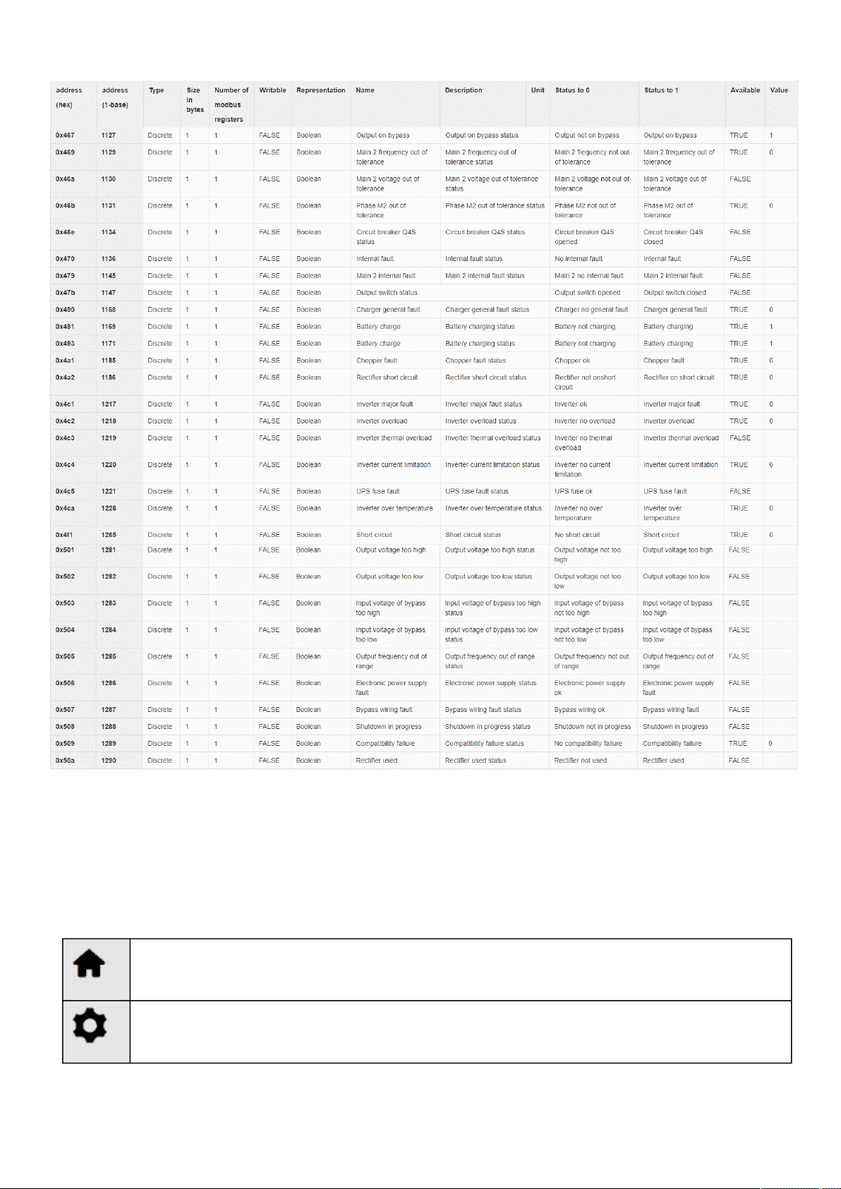
Configuring the Network Module settings
Servicing the Network Management Module – 108
3.5 Configuring the Network Module settings
UseEaton UPSNetwork Module web interface to configure the UPS Network Module.
Main web interface menus are described below:
Home page with overview of the UPS/Module status (Synoptic with measures, Active alarms, Meters, Outlet status,…).
Module settings (Date&Time, Users, Network, Protocols, Certificates, Email, My Preferences, …).

Configuring/Commissioning/Testing LDAP
Servicing the Network Management Module – 109
1.
2.
3.
4.
a.
b.
5.
6.
7.
List of Alarms with date, time and description.
Power quality meters, Battery information and measure logs.
Entire UPS Control, Battery test, Outlets control.
Scheduled Shutdown, Agents list, Agent Settings, Power Outage Policy.
Sensors (only displayed when sensors have been discovered in card administration)
Card administration (Firmware upgrade, reboot, save and restore, commissioning,...)
3.6 Configuring/Commissioning/Testing LDAP
3.6.1 Commissioning
Refer to the section
Contextual Help>>>Settings>>>Users to get help on the configuration.
3.6.1.1 Configuring connection to LDAP database
This step configures the LDAP client of the network module to request data from an LDAP base.
Activate LDAP.
Define security parameters according to LDAP servers' requirements.
Configure primary server (and optionally a secondary one).
If security configuration needs server certificate verification, import your LDAP server certificate.
Refer to the section to get help on certificate import.
In case LDAP server certificate is self-signed, import the self-signed certificate in the
Trusted remote certificate
list for
LDAP
service.
in case LDAP server certificate has been signed by a CA, import the corresponding CA in the
Certificate
authorities (CA)
list for
LDAP
service.
Configure credentials to bind with the LDAP server or select
anonymous
if no credentials are required.
Configure the
Search base DN
.
Configure the request parameters (see examples below).
3.6.1.1.1 Typical request parameters
ParameterOpenLDAPActive Directory™ with POSIX
account activated
Active Directory™
User base DNou=users, dc=example, dc=comou=users, dc=example, dc=comou=users, dc=example, dc=com
User name attributeuiduidsAMAccountName
UID attributeuidNumberuidNumberobjectSid:S-1-5-xx-yy-zz (domain SID)

Configuring/Commissioning/Testing LDAP
Servicing the Network Management Module – 110
1.
2.
3.
1.
2.
1.
2.
3.
4.
1.
2.
3.
4.
ParameterOpenLDAPActive Directory™ with POSIX
account activated
Active Directory™
Group base DNou=groups, dc=example, dc=comou=groups, dc=example, dc=comou=groups, dc=example, dc=com
Group name attributegidgidsAMAccountName
GID attributegidNumbergidNumberobjectSid:S-1-5-xx-yy-zz (domain SID)
3.6.1.2 Testing connection to LDAP database
Refer to the section
Information>>>CLI>>>ldap-testto get help on the CLI command.
To test connection to the LDAP database:
Connect to the CLI.
Launch
ldap-test --checkusername
command.
In case of error, use the
verbose
option ofthe command to investigate the reason.
3.6.1.3 Map remote users to profile
Configure the rules to mapped LDAP users to profile:
Enter LDAP group name.
Select the profile to assigned.
You can define up to 5 mapping rules.
All LDAP users belonging to the configured LDAP group will have permissions granted by the associated profile.
3.6.1.4 Testing profile mapping
Refer to the section
Information>>>CLI>>>ldap-testto get help on the CLI command.
To test LDAP users profile mapping:
Connect to the CLI.
Launch
ldap-test --checkmappedgroups
command.
This command will verify each mapped group exists in the LDAP base and will display the associated local profile.
In case of error, use the
verbose
option ofthe command to investigate the reason.
3.6.1.5 Define LDAP user's preferences
This step configures the user's preferences to apply to
all LDAP users.
3.6.2 Testing LDAP authentication
Refer to the section
Information>>>CLI>>>ldap-test to get help on the CLI command.
Connect to the CLI.
Launch
ldap-test --checkauth
command.
This command will verify an LDAP user can authenticate using his username and password and will display its local
profile.
In case of error, use the
verbose
option ofthe command to investigate the reason
This step is mandatory and configures the Network module to give permissions to the LDAP users.
Users not belonging to a group mapped on a profile will be rejected.
If a user belongs to multiple LDAP groups mapped to different profiles, the behavior is undefined.

Pairing agent to the Network Module
Servicing the Network Management Module – 111
•
•
•
•
•
•
•
•
•
•
•
•
•
•
•
•
3.6.3 Limitations
If the same username exists in both local and LDAP databases, the behavior is undefined.
If a user belongs to multiple LDAP groups mapped to different profiles, the behavior is undefined.
No client certificate provided. It is not possible for the server to verify the client authenticity.
It is not possible to configure LDAP to work with 2 different search bases.
LDAP user's preferences are common to
all LDAP users.
LDAP users cannot change their password through the Network Module.
The remote groupname entered in profile mapping settings must be composed only of alphanumerics, underscore
and hyphen characters (but this last one can't be at the beginning).
3.7 Pairing agent to the Network Module
Authentication and encryption of connections between the UPS network module and shutdown agents is based on matching
certificates.
3.7.1 Pairing with credentials on the agent
STEP 1: Action on the agent (IPP or IPM).
1. Connect to the web interface of the agent.
2. Detect the UPS Network Module with an Address(es) scan, select Override global authentication settings and type the UPS
Network Module credentials.
3.7.2 Pairing with automatic acceptance (recommended if done in a
secure and trusted network)
Pairing with automatic acceptance of shutdown agents and UPS network modules is recommended in case the installation is done
in a secure and trusted network, and when certificates cannot be created in other ways.
STEP 1: Action on the Network Module
1.Connect to the Network Module
On a network computer, launch a supported web browser. The browser window appears.
In the Address/Location field, enter: https://xxx.xxx.xxx.xxx where xxx.xxx.xxx.xxx is the static IP address of the
Network Module.
The log in screen appears.
Enter the user name in the User Name field.
Enter the password in the Password field.
Click Sign In. The Network Module web interface appears.
2. Navigate to Protection/Agents list page
3. In the Pairing with shutdown agentssection, select the time to accept new agents and press the Start button and the
pressContinue. During the selected timeframe, new agent connections to the Network Module are automatically trusted and
accepted.
STEP 2: Action on the agent(IPP)while the time to accepts new agents is running on the Network Module:
Connect to the web interface of the agent.
Detect the UPS Network Module with a Quick scan, Range scan or an Address(es) scan.
Right-click on the UPS Network Module when discovered and then Set aspower source,Configure it, andSave it.
STEP 3: Action on the Network Module
1. Make sure all listed agents in the card (Protection/Agents list) belong to your infrastructure, if not, access may be revoked using
theDeletebutton.
2. If the time for pairing still runs, you can stop it. Press Stop in thePairing with shutdown agentssection.
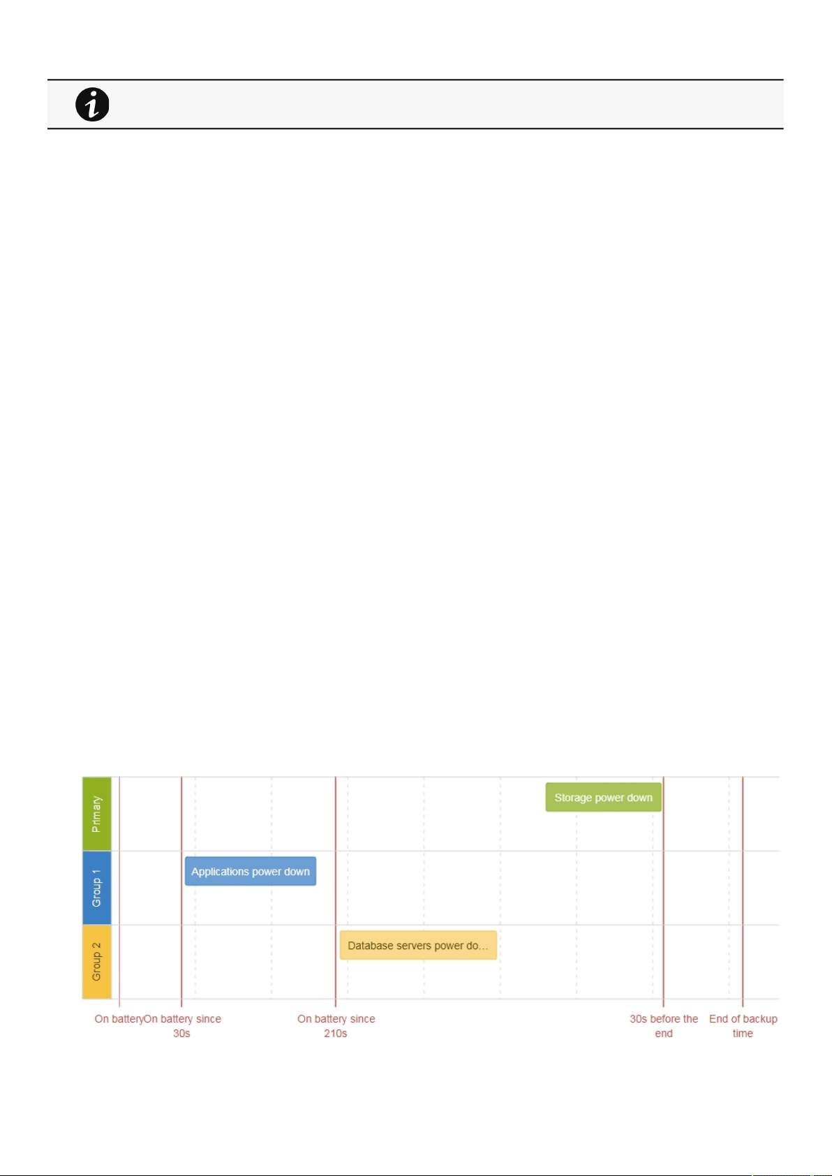
Powering down/up applications (examples)
Servicing the Network Management Module – 112
•
•
•
•
•
•
3.7.3 Pairing with manual acceptance
Manual pairing provides the maximum security.
STEP 1: Action on the agent(IPP)
1. Connect to the web interface of the agent
2. Detect the UPS Network Module with a Quick scan, Range scan or an Address(es) scan.
3. Define the power source
Note: After that stage, the agent creates a client certificate. The power source could show a communication loss since the
current client certificate is not trusted by the Network Module.
4.Copy the agent certificate file client.pemthat is located in the folderEaton\IntelligentPowerProtector\configs\tls.STEP 2: Action
on the Network Module
1.Connect to the Network Module
On a network computer, launch a supported web browser. The browser window appears.
In the Address/Location field, enter: https://xxx.xxx.xxx.xxx where xxx.xxx.xxx.xxx is the static IP address of the
Network Module.
The log in screen appears.
Enter the user name in the User Name field.
Enter the password in the Password field.
Click Sign In. The Network Module web interface appears.
2. Navigate to Settings/Certificatepage
3. In theTrusted remote certificates section, click Import, selectProtected applications (MQTT) and thenclick on CONTINUE
4. Select the client.pem file previously saved, click Open. Communication with the agent is restored.
3.8 Powering down/up applications (examples)
3.8.1 Powering down IT system in a specific order
3.8.1.1 Target
Powering down applications first (when on battery for 30s), database servers next (3min after the applications), and storage last (as
late as possible).
STEP 1 and STEP2 can be done either ways.

Powering down/up applications (examples)
Servicing the Network Management Module – 113
•
•
•
•
•
•
3.8.1.2 Step 1: Installation setup
3.8.1.2.1 Objective
Use load segmentation provided by the UPS to independently control the power supply of each IT equipment categories
(Applications, Database servers, Storage).
It also allows IT equipment to sequentially restart on utility recovery (
Restart sequentially the IT equipment on utility recovery).
3.8.1.2.2 Resulting setup
UPS provides outlets (Group 1 and Group 2) and a primary output.
Connections to UPS are done as described below:
Group 1: Applications
Group 2: Database servers
Primary: Storage
3.8.1.3 Step 2: Agent settings
3.8.1.3.1 Objective
Ensure IT solution is shutdown gracefully.
3.8.1.3.2 Resulting setup
1. InstallIPPSoftware on each server (Application, Database servers, Storage) and register the UPS load segment as power source:
Applications:Group 1
Database servers:Group 2
Storage: Entire UPS
2. Pair agent to the Network Module (
Pairing agent to the Network Module).
When done, each server appears in the Agent list.
3.Navigate toProtection/Agent settingspage.
4. Set the OS shutdown duration to the time needed for your server to shutdown gracefully.
This will make sureIPPshutdowns your servers before the load segment is powered down.
As a result, it will define the overall shutdown sequence duration for each load segments.
3.8.1.4 Step 3: Power outage policy settings
3.8.1.4.1 Objective
Use load segment policies to define shutdown sequencing.
3.8.1.4.2 Resulting setup
1. Navigate to
Protection/Power outage policypage of the Network Module
When primary shuts OFF, both group 1 and group 2 shut OFF immediately.
For examples of Agent settings, see the Agent settings examples section.
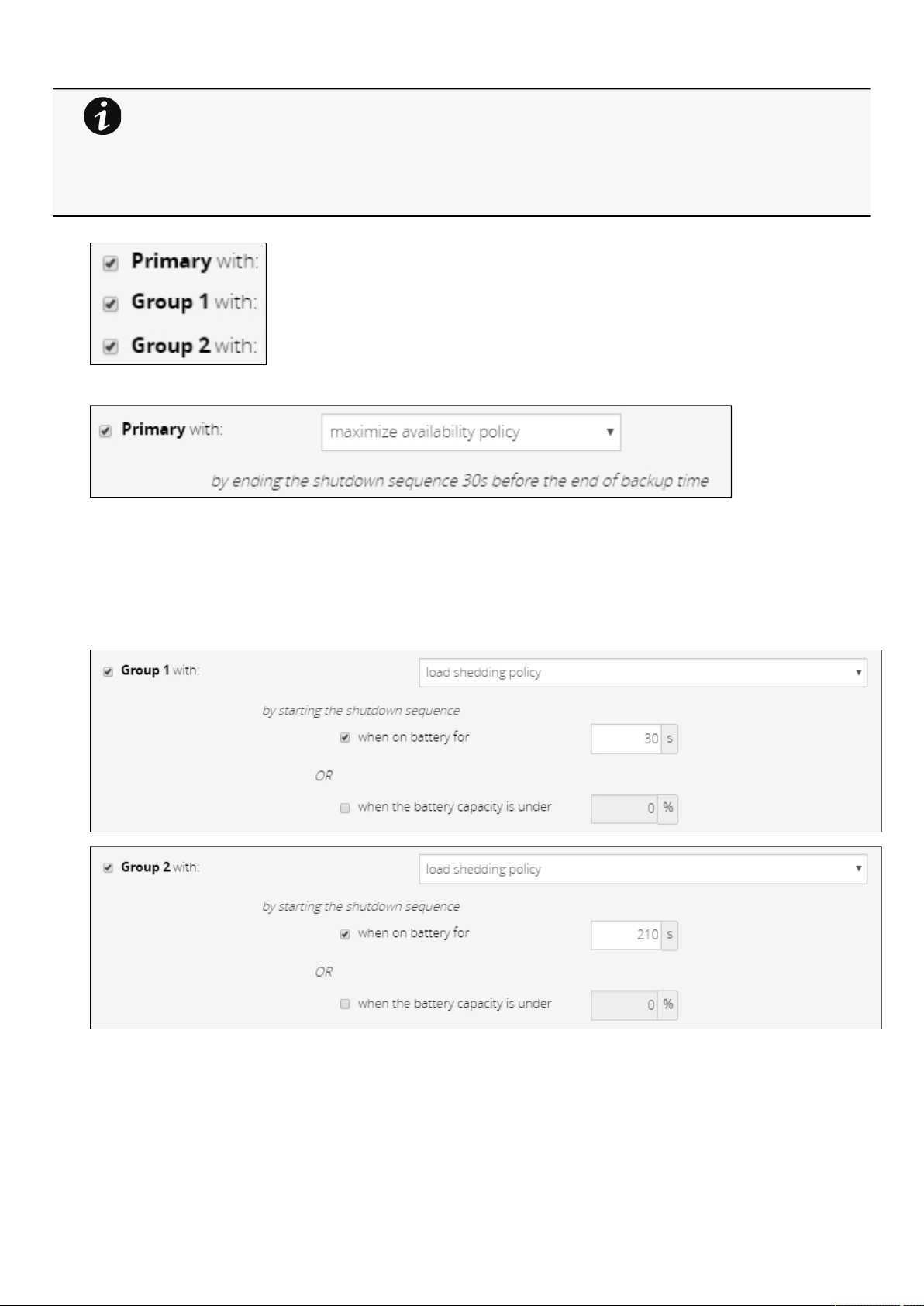
Powering down/up applications (examples)
Servicing the Network Management Module – 114
2. Enable policies of Primary, Group 1 and Group 2.
3. Set Primary to: maximize availability policy.
Storage is the last one to power down, its availability is maximized, and its shutdown will end 30s before the end of backup
time.
4. Set Group 1 and Group 2 to:
load shedding policy.
Applications must shutdown first so Group 1 has been set to start shutdown when on battery for 30s.
Servers must shutdown second, so Group 2has been set to start shutdown when on battery for 210s, so 3min after the
applications.
•
•
•
•
For examples of Power outage policy, see the following sections:
Maximize availability policy example
Immediate graceful shutdown policy example
Load shedding policy examples
Custom policy examples
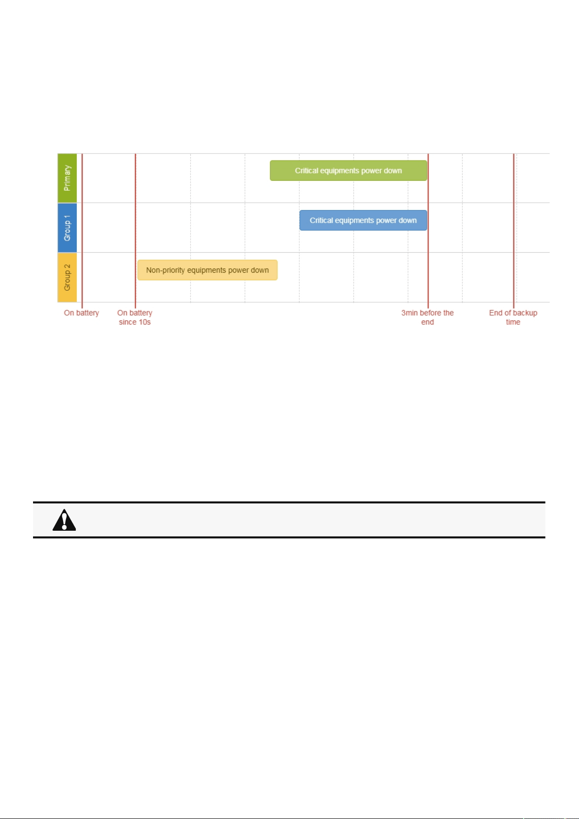
Powering down/up applications (examples)
Servicing the Network Management Module – 115
•
•
•
•
3.8.2 Powering down non-priority equipment first
3.8.2.1 Target
Powering down non-priority equipment first (immediately) and keep battery power for critical equipment.
Powering down critical equipment 3min before the end of backup time.
3.8.2.2 Step 1: Installation setup
3.8.2.2.1 Objective
Use load segmentation provided by the UPS to independently control the power supply of each IT equipment categories
(Applications, Database servers, Storage).
Load segmentation also allows IT equipment to restart sequentially on utility recovery(
Restart sequentially the IT equipment on
utility recovery).
3.8.2.2.2 Resulting setup
UPS provides outlets (Group 1 and Group 2) and a primary output.
Connections can be done as described below:
Group 2: non-priority equipment
Group 1: critical equipment
Primary:criticalequipment
3.8.2.3 Step 2: Agent settings
3.8.2.3.1 Objective
Ensure IT solution is shutdown gracefully.
3.8.2.3.2 Resulting setup
1. InstallIPPSoftware on each server (Application, Database servers, Storage) and register the UPS load segment as power source:
Critical equipment:Group 1
When primary shuts OFF, both group 1 and group 2 shut OFF immediately.
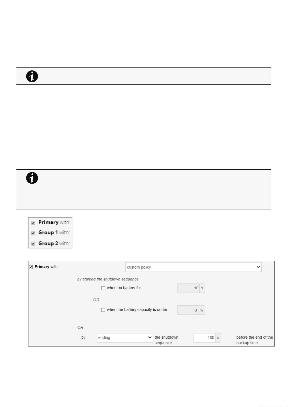
Powering down/up applications (examples)
Servicing the Network Management Module – 116
•
•
Non-priority equipment:Group 2
Critical equipment: Entire UPS
2. Pair agent to the Network Module (Pairing agent to the Network Module).
When done, each server appears in the Agent list.
3.Navigate toProtection/Agent settingspage
4. Set the OS shutdown duration to the time needed for your server to shutdown gracefully.
This will make sureIPPshutdowns your servers before the load segment is powered down.
As a result, it will define the overall shutdown sequence duration for each load segments.
3.8.2.4 Step 3: Power outage policy settings
3.8.2.4.1 Objective
Use load segment policies to define shutdown sequencing.
3.8.2.4.2 Resulting setup
1. Navigate to
Protection/Power outage policypage on the Network Module
2. Enable policies of Primary, Group 1 and Group 2.
3. Set Primary and Group 1 to:
custom policyand set it to end shutdown sequence 180s before the end of backup time.
For examples of Agent settings, see the Agent settings examples sections.
•
•
•
•
For examples of Power outage policy, see the following sections:
Maximize availability policy example
Immediate graceful shutdown policy example
Load shedding policy examples
Custom policy examples
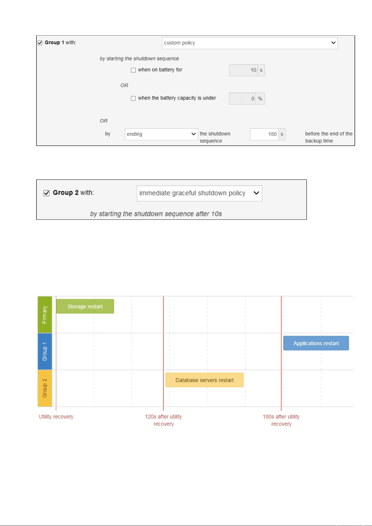
Powering down/up applications (examples)
Servicing the Network Management Module – 117
Critical equipment is the last one to power down, their availability will be maximized and their shutdown will end 180s before
the end of backup time.
4. Set Group 2 to:immediate graceful shutdown policy.
Non-priority equipmentimmediately shuts down when on battery for 10s to keep battery power for critical equipment.
3.8.3 Restart sequentially the IT equipment on utility recovery
3.8.3.1 Target
Restart the storage first (right after utility recovery), database servers next(2min after utility recovery) and applications last (3min
after utility recovery).
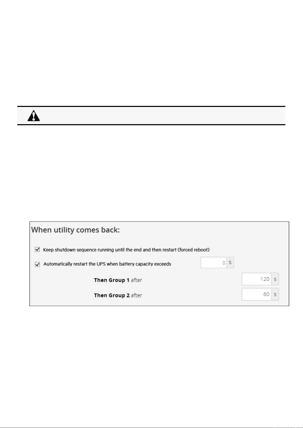
Powering down/up applications (examples)
Servicing the Network Management Module – 118
•
•
•
3.8.3.2 Step 1: Installation setup
3.8.3.2.1 Objective
Use load segmentation provided by the UPS to independently control the power supply of each IT equipment categories
(Applications, Database servers, Storage).
This will allow to restart sequentially the IT equipment on utility recovery.
3.8.3.2.2 Resulting setup
UPS provides outlets (Group 1 and Group 2) and a primary output.
Connections to UPS can be done as described below:
Group 1: Applications
Group 2: Database servers
Primary: Storage
3.8.3.3 Step 2: Power outage policy settings
3.8.3.3.1 Objective
Use load segment restart settings to define restart sequencing.
3.8.3.3.2 Resulting setup
1. Navigate to
Protection/Power outage policypage and to the When utility comes backsection.
2.Enable the "Keep shutdown sequence running until the end and then restart (forced reboot)".
3. Enable the "Automatically restart the UPS when battery capacity exceeds" and set it to 0%.
The storage will restart first, right after utility recovery without waiting the battery capacity to exceed a % limit.
4. Set Then Group 1 after to 120s.
The database servers will restart 120s after the utility recovery.
5. Set Then Group 2 after to 60s.
The database servers will restart 180s after the utility recovery.
When utility recovers, primary starts immediately.
Checking the current firmware version of the Network Module
Servicing the Network Management Module – 119
•
•
•
1.
2.
3.9 Checking the current firmware version of the Network
Module
Currentfirmware of the Network Module can be accessed in :
The footer: Version : x.xx.x
The Card menu :
Card>>>System information>>>FW information: Firmware version x.xx.x
The Card menu : Card>>>Administration>>>Network module firmware: Active FW version x.xx.x
3.10 Accessing to the latest Network Module firmware/driver/
script
Download the latest Eaton Network Module firmware, driver or script from the Eaton websitewww.eaton.com/downloads.
3.11 Upgrading the card firmware (Web interface / shell script)
3.11.1 Web interface
To upgrade the Network module through the Web interface, refer to the section:
Firmware upgrade through the Web interface.
3.11.2 Shell script
3.11.2.1 Prerequisite
Shell script uses the following tools: sshpass, scp.
To get it installed on your Linux host, use the following commands.
Debian/Ubuntu
$ sudo apt-get install sshpass scp
RedHat/Fedora/CentOS
$ sudo dnf install sshpass scp
Make shell script executable:
$ chmod 700 install_updatePackage.sh
3.11.2.2 Procedure
To upgrade the Network module using:
Open a shell terminal on your computer (Linux or cygwin; meaning real or emulated Linux operating system).
Use the shell script
install_updatePackage.sh
For instructions on accessing to the latest firmware and script, refer to: Accessing to the latest firmware
and script

Changing the RTC battery cell
Servicing the Network Management Module – 120
Usage: 'install_updatePackage.sh' [options]
Upgrade tool
Mandatory arguments are -f, -i, -u and -p
-h : show help
-f <path> : path of the upgrade file
-u <username> : username of a card user allowed to start upgrade
-p <password> : user password
-i <ipaddress> : ip address of the card to upgrade
-r : reboot the card after upgrade
3.11.3 Example:
$ ./install_updatePackage.sh -u admin -p <mypassword> -f FW_Update.tar -i <cardIpAddress> -r
STARTING UPDATE FROM: [FW_Update.tar] to [X.X.X.X]
Transfer by scp (FW_Update.tar) to [X.X.X.X]
Warning: Permanently added 'X.X.X.X' (ECDSA) to the list of known hosts.
Transfer done.
Check running upgrade status ...
Check firmware binary signature
Uncompress and flash upgrade - inProgress(%):11
Uncompress and flash upgrade - inProgress(%):28
Uncompress and flash upgrade - inProgress(%):44
Uncompress and flash upgrade - inProgress(%):61
Uncompress and flash upgrade - inProgress(%):78
Uncompress and flash upgrade - inProgress(%):92
Uncompress and flash upgrade - inProgress(%):100
Uncompress and flash upgrade - inProgress(%):100
Uncompress and flash upgrade
Executing post post_upgrade.sh script upgrade
Upgrade done
Warning: Permanently added 'X.X.X.X' (ECDSA) to the list of known hosts.
Rebooting...
res: Y
Update: OK
3.12 Changing the RTC battery cell
1.Access the Network Module, and then disconnect the Network cable, if needed.
2. Unscrew the Network Module and remove it from the slot.
3. Locate the RTC battery cell located on the back of the Network Module.4. Get a new battery cell (CR1220 type).

Changing the RTC battery cell
Servicing the Network Management Module – 121
5. Replace the battery cell, the positive mark (+) should be visible when inserting it.
6. Replace the Network Module and secure the screw, reconnect the Network cableif it was unplugged during the operation.
7. Connect the Network Module and set the date and time. For more information, see the Date & Timesection.

Updating the time of the Network Module precisely and permanently (ntp server)
Servicing the Network Management Module – 122
1.
2.
3.13 Updating the time of the Network Module precisely and
permanently (ntp server)
For an accurate and quick update of the RTC for the Network Module, we recommend implementing a NTP server as time source
for the Network Module.
LANs have aninternal NTP server (Domain Controller, mail servers, Outlook servers are generally time servers too) but you can use
a public ntp server like pool.ntp.org (after addition of the related rules to your firewall system).
For more information, see the
Date and Time section.
3.14 Synchronizing the time of the Network Module and the UPS
3.14.1 Automatic time synchronization
3.14.1.1 Every day at 5 a.m.
The UPS time (local time) is synchronized with the Network Module.
3.14.1.2 If the Network Module time is lost
The Network Module and the UPS time is synchronized with the oldest time between the last know Network Module time and the
UPS time.
3.14.2 Manual time synchronization
3.14.2.1 From the Network Module
On the Network Module, navigate to
Settings>>>Date & Time section and update the time.
The UPS time (local time) is directly synchronized with the Network Module.
3.14.2.2 From the UPS
3.15 Changing the language of the web pages
Update thelanguage of the web page in the Settings menu.
Navigate to
Settings>>>My preferences>>>Language.
Select the language, and then press the Save button.
This section is valid only when the UPS can manage date and time (refer to the UPS user manual for
confirmation).
The Network Module use UTC time and manage the time zone and the DST.
The UPS manage only the local time.
When the time is updated on the UPS, it is not synchronized on the Network Module.
The language of the login page is English by default or browser language when it is supported.
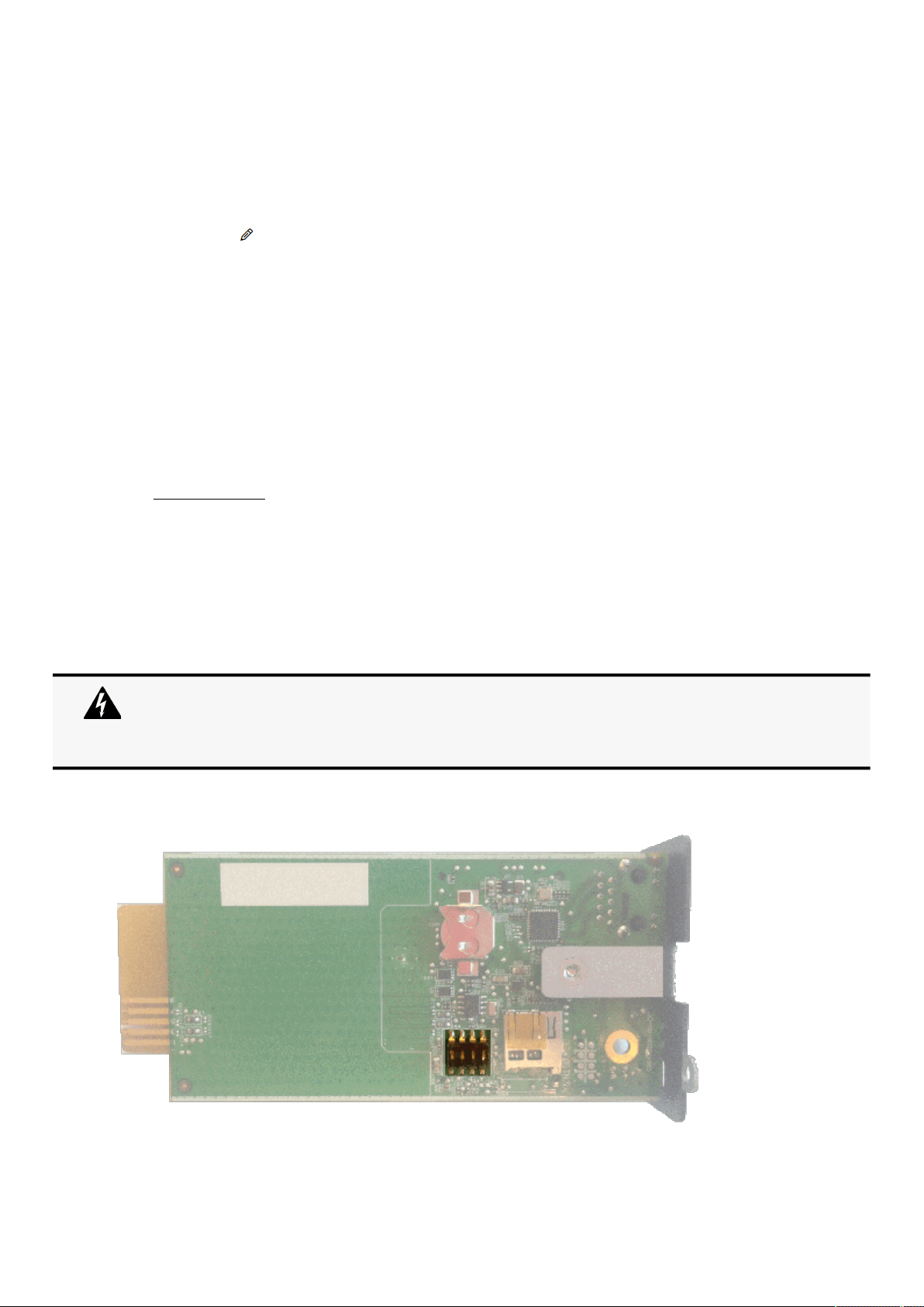
Resetting username and password
Servicing the Network Management Module – 123
1.
2.
3.
4.
•
•
•
5.
6.
1.
2.
3.
4.
1.
2.
3.
4.
3.16 Resetting username and password
3.16.1 As an admin for other users
Navigate to
Settings>>>Users.
Press the pen icon to edit user information.
Change username and save the changes.
Select Reset password and choosefrom the following options :
Generate randomly
Enter manually
Force password to be changed on next login
Enter your own password to confirm the changes.
Save the changes.
3.16.2 Resetting its own password
Navigate to
Settings>>>My preferences>>>Profile.
Press Change password
Enter your current password, the new password twice.
Press Continue to save the changes.
3.17 Recovering main administrator password
To recover the mainadministrator password,ask another administrator to initialize the password.
If it is not possible, proceed to the card sanitization:
Access the Network Module, disconnect the Network cable, if needed.
Unscrew the Network Module and remove it from the slot.
Locate the SANITIZATION switch that is located on the back of the Network Module.
Peel off the protection :
Below instruction will sanitize the card and blank all the data.
Depending on your network configuration, the Network Module may restart with a different IP address.
Only main administrator user will remain with default login and password.
Refresh the browser after the Network module reboot time to get access to the login page.
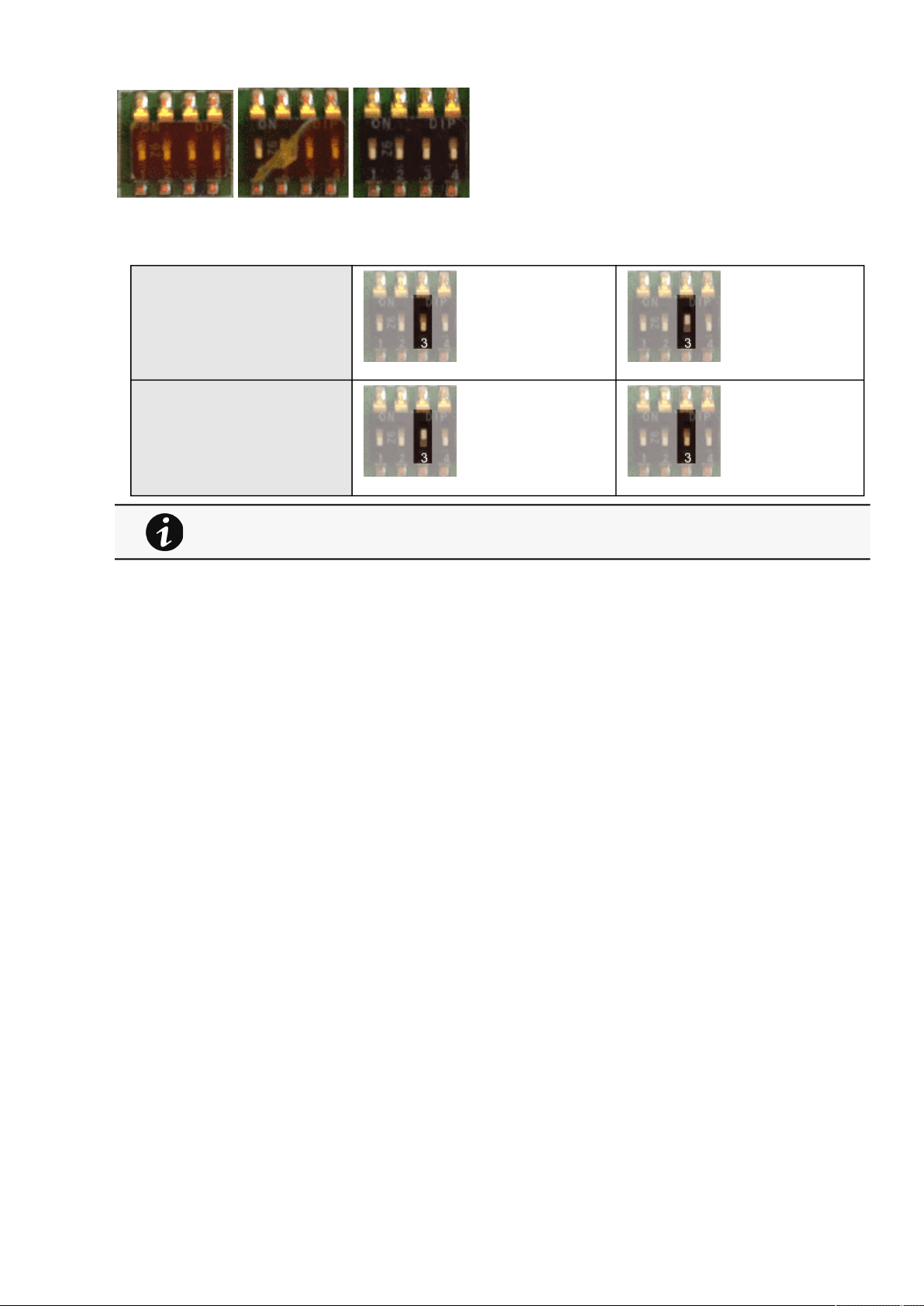
Switching to static IP (Manual) / Changing IP address of the Network Module
Servicing the Network Management Module – 124
5.
6.
7.
8.
•
•
•
Change the position of switch number 3, this change is detected during next power ON and the sanitization will be
applied :
Case 1 :
Case 2 :
Replace the Network Module and secure the screw, connect the Network cable, if needed.
Connect the Network Module byusing the default credentials of the main administrator : admin/admin.
You will beforced tochange the password accordingly to the current password strength rules.
3.18 Switching to static IP (Manual) / Changing IP address of the
Network Module
Administrators can switch to static IPin the Settings menu and change the IP address of the Network Module:
1.Navigate to
Settings>>>Network>>>IPV4.
2. Select Manual (Static IP).
3. Input the following information:
IPv4 Address
Subnet Mask
Default Gateway
4. Save the changes.
3.19 Reading product (UPS) information in a simple way
3.19.1 Web page
The product information is located in the
Home page,specifically with the Details button on the top of the diagram and in the
Meters menu.
Changes of the switches 1, 2 or 4 has no effect.

Subscribing to a set of alarms for email notification
Servicing the Network Management Module – 125
•
•
•
•
•
3.20 Subscribing to a set of alarms for email notification
3.20.1 Example #1: subscribing only to one alarm (load unprotected)
Follow the steps below:
1.Navigate to Settings>>>Email>>>Email sending configuration.
2. Press the button
New to create a new configuration.
3. Select:
Active: Yes
Configuration name: Load unprotected notification
Email address:[email protected]
Notify on events: Active
Always notify events with code: 81E (Load unprotected)
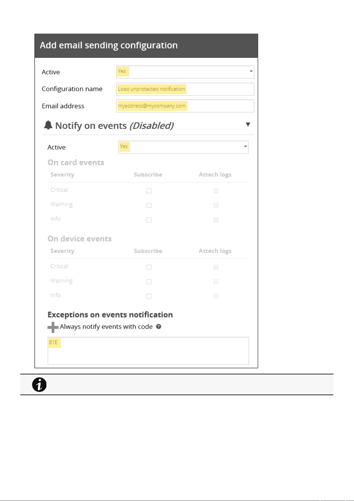
Subscribing to a set of alarms for email notification
Servicing the Network Management Module – 126
4. Press Save, the table will show the new configuration.
Logs will be attached by default in that example even if there is no subscription on card or device
events.

Subscribing to a set of alarms for email notification
Servicing the Network Management Module – 127
•
•
•
•
•
•
3.20.2 Example #2: subscribing to all Critical alarms and some specific
Warnings
Follow the steps below:
1.Navigate to Settings>>>Email>>>Email sending configuration.
2. Press the button
Newto create a new configuration.
3. Select:
Active: Yes
Configuration name: ALL Critical and User account Warning notification
Email address: [email protected]
Notify on events: Active
Subscribe to Critical card events and Critical device events
Always notify events with code:0800700,0800900 (User account - password expired,User account- locked)
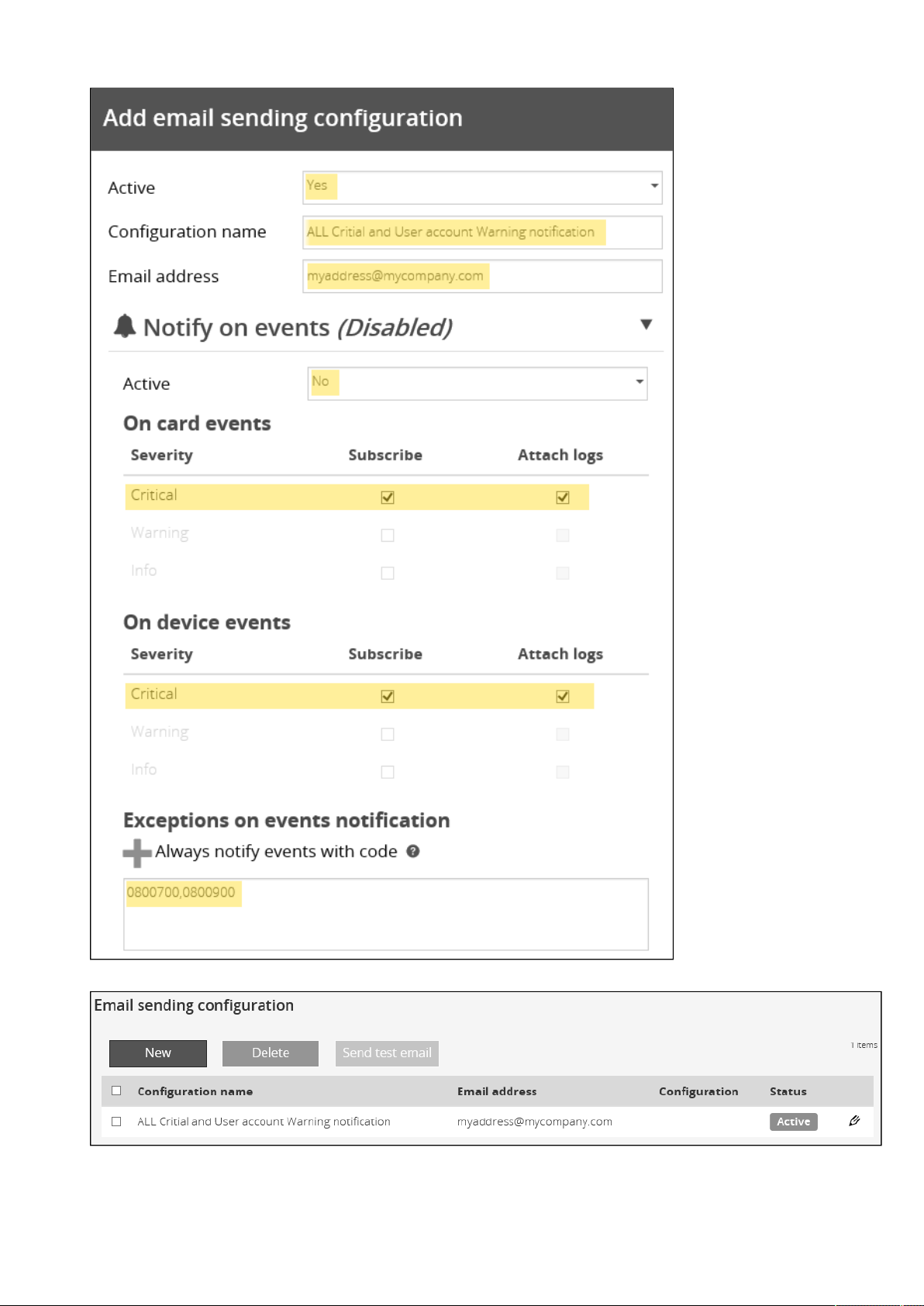
Subscribing to a set of alarms for email notification
Servicing the Network Management Module – 128
4. PressSave, the table will show the new configuration.
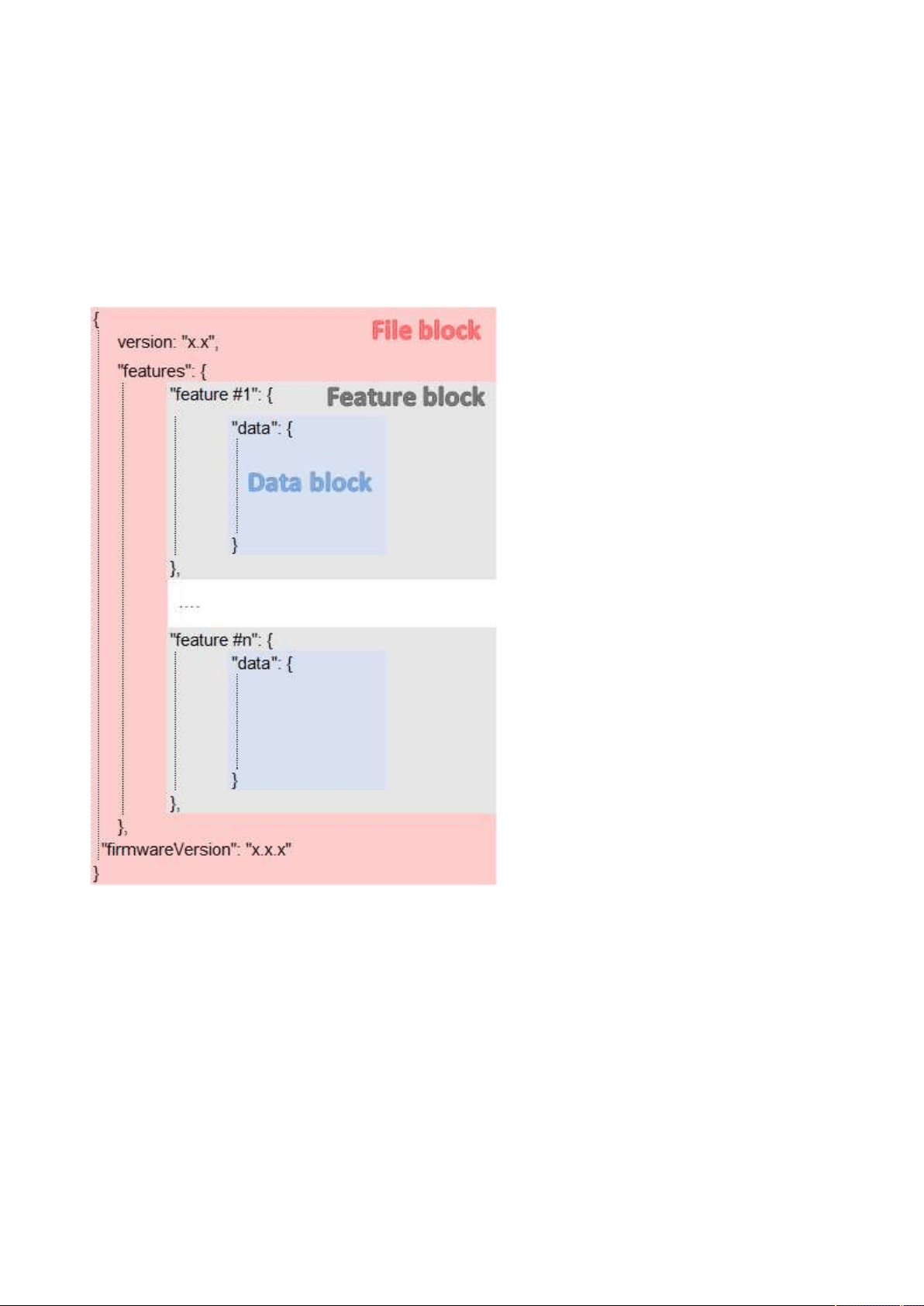
Saving/Restoring/Duplicating Network module configuration settings
Servicing the Network Management Module – 129
3.21 Saving/Restoring/Duplicating Network module configuration
settings
3.21.1 Modifying the JSON configuration settings file
3.21.1.1 JSON file structure
The JSON file is structured into 3 blocks:
3.21.1.1.1 File block
File block cannot be modified, this is the mandatory structure of the JSON file.
3.21.1.1.2 Feature block
Feature block contains the full definition of a feature.
If it is removed from the JSON file, this feature settings will not be updated/restored in the card.
3.21.1.1.3 Data block
Data block contains all the feature settings values.
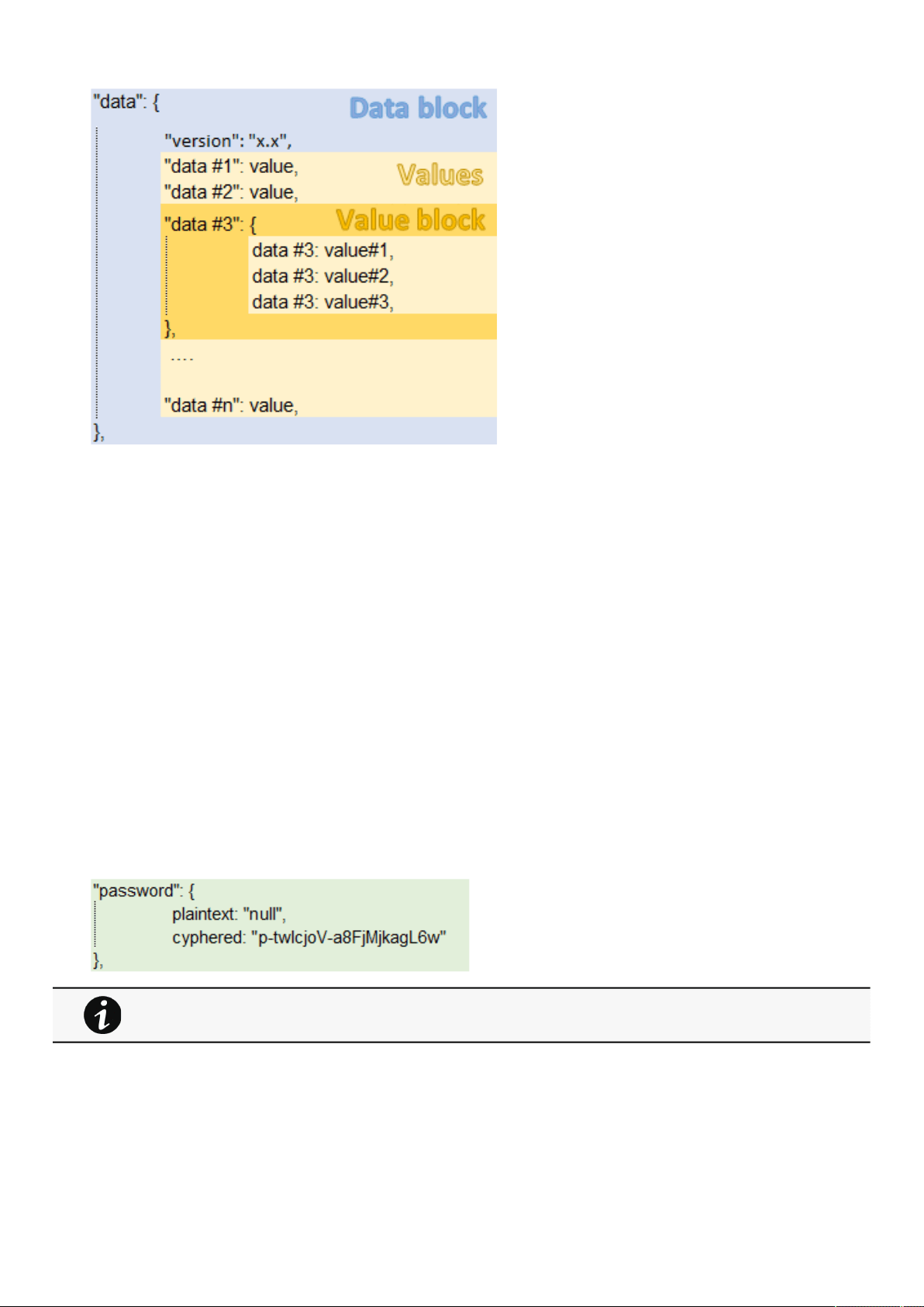
Saving/Restoring/Duplicating Network module configuration settings
Servicing the Network Management Module – 130
a Data block
Data block cannot be modified, this is the mandatory structure of the JSON file.
b Value block
If some values inside the Value block need to be kept, Value block structure cannot be modified, this is the mandatory structure of
the JSON file.
If it is removed from the JSON file, these values will not be updated/restored.
c Values
Values can be kept as is, modified or removed.
Removed values will not be updated/restored.
3.21.1.2 Sensitive data (like passwords)
JSON file structure will slightly varies if sensitive data are exported with passphrase or not.
3.21.1.2.1 The JSON file is saved using passphrase (preferred)
All sensitive data will have below structure:
3.21.1.2.2 The JSON file is saved without passphrase
All sensitive data will have below structure:
When restoring the file, the corresponding setting will be updated based on the cyphered value.
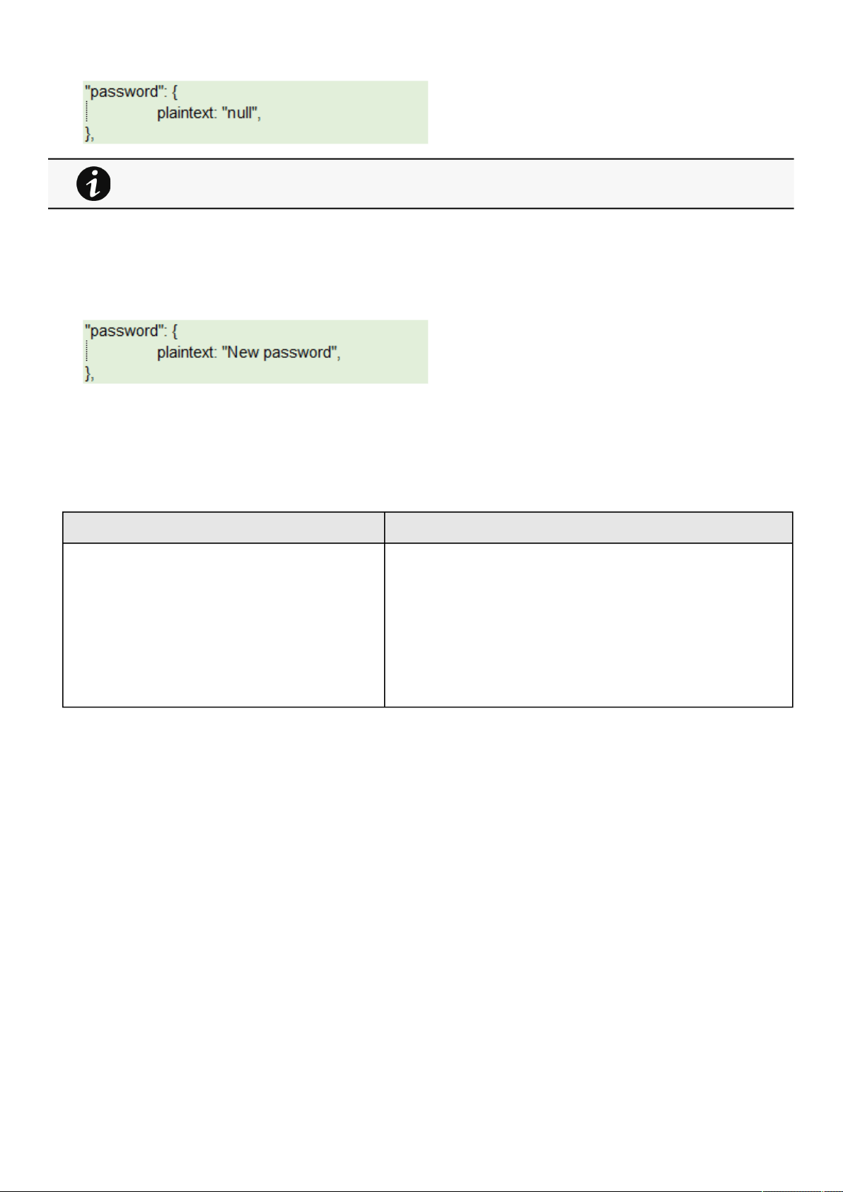
Saving/Restoring/Duplicating Network module configuration settings
Servicing the Network Management Module – 131
3.21.1.3 Modifying JSON file examples
3.21.1.3.1 Modifying sensitive data
To change sensitive data, plain text must be filled with the new value
and the Cyphered entry (if existing) must be removed:
3.21.1.3.2 Adding local users
Adding or modifying local users is not yet available, only the predefined account (main administrator) can be modified.
3.21.1.3.3 Modifying SNMP settings
Original file:Modified file:
SNMP disabledSNMP enabled on port 161
SNMPv1 disabled
SNMPv3 enabled
2 x accounts
1 x read only user (enabled) with Auth-Priv security level and passwords
1x read write user (enabled) with Auth-Priv security level and passwords
1 x active trap
When restoring the file, the corresponding setting will not be set.
This may lead to restoration failure if corresponding setting was not previously set with a valid value.
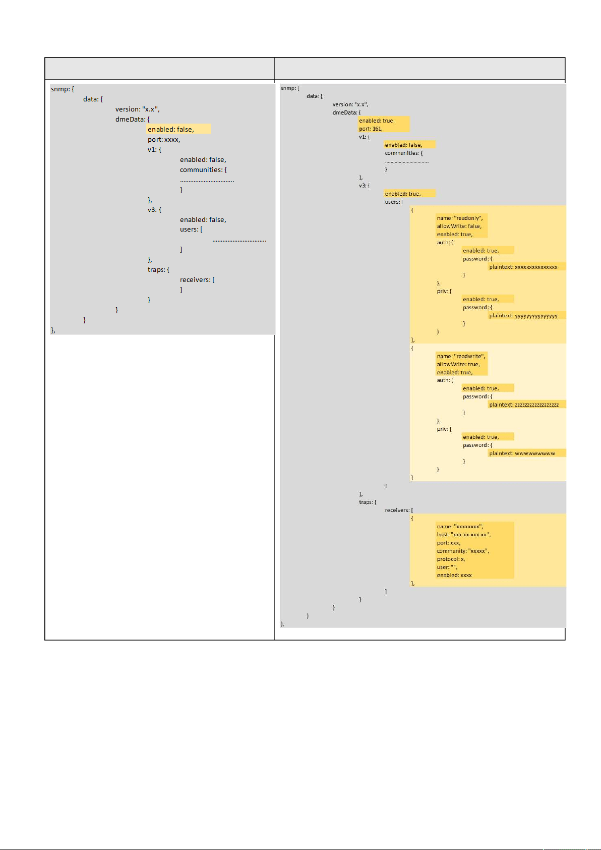
Saving/Restoring/Duplicating Network module configuration settings
Servicing the Network Management Module – 132
Original file:Modified file:
3.21.1.3.4 Making a partial update/restoration
a Example: Updating/Restoring onlyLDAP settings
If you restore below JSON content, only LDAP settings will be updated/restored, everything else will remain unchanged.

Saving/Restoring/Duplicating Network module configuration settings
Servicing the Network Management Module – 133
{
"version": "x.x",
"features": {
"ldap": {
"data": {
"version": "x.x",
"certificateData": [],
"dmeData": {
"enabled": true,
"baseAccess": {
"security": {"ssl": 1,"verifyTlsCert": false},
"primary": {"name": "Primary","hostname": "xxxxxxxxx","
port": xxxx},
"secondary": {"name": "xxxxxx","hostname": "xxxxxx","
port": xxxx},
"credentials": {
"anonymousSearchBind": false,
"searchUserDN":
"CN=xxxx,OU=xxxx,OU=xxxx,OU=xxxx,DC=xxxx,DC=xxxx",
"password": {"plaintext": null}},
"searchBase": {"searchBaseDN": "DC=xxx,DC=xxx,DC=xxx"
}
},
"requestParameters": {
"userBaseDN": "OU=xxxx,DC=xxxx",
"userNameAttribute": "xxxx",
"uidAttribute":"objectSid:x-x-x-xx-xxxxxxxxxx-
xxxxxxxxxx-xxxxxxxxxx",
"groupBaseDN": "OU=xxxx,DC=xxxx",
"groupNameAttribute": "xx",
"gidAttribute":"objectSid:x-x-x-xx-xxxxxxxxxx-
xxxxxxxxxx-xxxxxxxxxx"
},
"profileMapping": [
{ "remoteGroup": "xxxxxxxxxxxxxx","profile": 1},
{ "remoteGroup": "xxxxxxxxxxxxxx","profile": 2},
{ "remoteGroup": "","profile": 0},
{ "remoteGroup": "","profile": 0},
{ "remoteGroup": "","profile": 0}
]
}
}
},
},
"firmwareVersion": "x.x.x"
}
3.21.1.4 Non-intuitive data values in the JSON file
DataValues example

Saving/Restoring/Duplicating Network module configuration settings
Servicing the Network Management Module – 134
Account servicepreferences>>>languagede: Deutsh
en: English
es: Español
fr: Français
it: Italiano
ja: 日本語
zh_Hans: 简体中文
zh_Hant:繁體中文
preferences>>>dateFormatY-m-d: YYYY-MM-DD
d-m-Y: DD-MM-YYYY
d.m.Y: DD.MM.YYYY
d/m/Y: DD/MM/YYYY
m/d/Y: MM/DD/YYYY
d m Y: DD MM YYYY
preferences>>>timeFormat1: 24h
0: 12h
preferences>>>temperatureUnit1: °C
2: °F
DataValues example
Card--
DataValues example
DatetimeZone"Europe/Paris","Africa/Johannesburg","America/
New_York","Asia/Shanghai"
Refer to the Web interface for the full list.
DataValues example
emailperiodicReport>>>periodicityEvery day
Every week
Every month
periodicReport>>>startTimetimestamp (unix)
DataValues example
LDAPbaseAccess>>>security>>>ssl1: None
2: Start TLS
3: SSL
baseAccess>>>profileMapping>>>profileadministrators
viewers
operators
DataValues example
Measure--
DataValues example

Saving/Restoring/Duplicating Network module configuration settings
Servicing the Network Management Module – 135
Modbusrtu>>>configuration>>>baudrate1: 1200pbs
2: 2400bps
3: 4800bps
4: 9600bps
5: 19200bps
6: 38400bps
7: 57600bps
8: 115200bps
rtu>>>configuration>>>parity1: None
2: Even
3: Odd
rtu>>>configuration>>>stopBits1: 1 Stop bit
2: 2 Stop bits
mapping>>>configurations>>>transport1: RTU
2: TCP
mapping>>>configurations>>>mapnetwork_card: Card System Information
modbus_ms: Eaton ModbusMS compatible
mapping>>>configurations>>>transportFilter*: Access to all
xx.xxx.xx.xx;yy.yyy.yy.yy;...: Access to a list of IP address
mapping>>>configurations>>>deviceID1 to 247
mapping>>>configurations>>>access0: None
1: Read only
3: Read/Write
mapping>>>configurations>>>illegalReadBehavior1: Return exception
2: return zeros
DataValues example
MQTT--
DataValues example
Power outage policyid1: Primary
2: Group 1
3: Group 2
DataValues example
Remote userpreferences>>>languagede: Deutsh
en: English
es: Español
fr: Français
it: Italiano
ja: 日本語
zh_Hans: 简体中文
zh_Hant:繁體中文

Saving/Restoring/Duplicating Network module configuration settings
Servicing the Network Management Module – 136
preferences>>>dateFormatY-m-d: YYYY-MM-DD
d-m-Y: DD-MM-YYYY
d.m.Y: DD.MM.YYYY
d/m/Y: DD/MM/YYYY
m/d/Y: MM/DD/YYYY
d m Y: DD MM YYYY
preferences>>>timeFormat1: 24h
0: 12h
preferences>>>temperatureUnit1: °C
2: °F
DataValues example
Schedulescheduler1: Primary
2: Group 1
3: Group 2
recurrence0: once
1: every day
2: every week
shutdownTimeStamptimestamp (unix)
restartTimeStamptimestamp (unix)
DataValues example
SMTP--
DataValues example
SNMPtraps>>>receivers>>>protocol1: SNMP v1
3: SNMP v2
traps>>>receivers>>>userUser configuration cannot be duplicated without manual
configuration through the Web interface.
DataValues example
Syslogservers>>>protocol1: UDP
2: TCP
servers>>>tcpframing1: TRADITIONAL
2: OCTET_COUNTING
DataValues example
Web server--
3.21.2 Saving/Restoring/Duplicating settings through the CLI
Navigate to
Information>>>CLI>>>save_configuration | restore_configuration section to get example on how to save and restore
settings through the CLI.

Saving/Restoring/Duplicating Network module configuration settings
Servicing the Network Management Module – 137
3.21.3 Saving/Restoring/Duplicating settings through the Web interface
Navigate to
Card>>>Administration section to getinformation on how to save and restore settings through the Web interface.

Cybersecurity considerations for electrical distribution systems
Securing the Network Management Module – 138
•
•
•
•
4 Securing the Network Management Module
4.1 Cybersecurity considerations for electrical distribution
systems
4.1.1 Purpose
The purpose of this section is to provide high-level guidance to help customers across industries and applications apply Eaton
solutions for power management of electrical systems in accordance with current cybersecurity standards.
This document is intended to provide an overview of key security features and practices to consider in order to meet industry
recommended standards and best practices.
4.1.2 Introduction
Every day, cyber-attacks against government and commercial computer networks number in the millions. According to U.S. Cyber
Command, Pentagon systems are probed 250,000 times per hour. Similar attacks are becoming more prevalent on other kinds of
information-based smart networks as well, such as those that operate buildings and utility systems. Whether the objective is to
steal intellectual property or halt operations, the tools and the techniques used for unauthorized network access are increasingly
sophisticated.
4.1.3 Connectivity—why do we need to address cybersecurity for
industrial control systems (ICS)?
There is increasing concern regarding cybersecurity across industries where companies are steadily integrating field devices into
enterprise-wide information systems. This occurs in discrete manufacturing and process industrial environments, a wide range of
general and specific purpose commercial buildings, and even utility networks. Traditionally, electrical systems were controlled
through serial devices connected to computers via dedicated transceivers with proprietary protocols. In contrast, today’s control
systems are increasingly connected to larger enterprise networks, which can expose these systems to similar vulnerabilities that
are typically found in computer systems. The differences between information technology (IT) and ICS networks can be
summarized as follows:
The main focus of the IT network is to ensure the
confidentiality and the integrity of the data using rigorous access
control and data encryption
The main focus of the ICS network is safety, availability, and integrity of data
Enterprise security protects the servers’ data from attack
Control system security protects the facility’s ability to safely and securely operate, regardless of what may befall the
rest of the network
4.1.4 Cybersecurity threat vectors
Cybersecurity threat vectors are paths or tools that an entity can use to gain access to a device or a control network in order to
deliver a malicious attack. Figure below shows examples of attack vectors on a network that might otherwise seem secure.
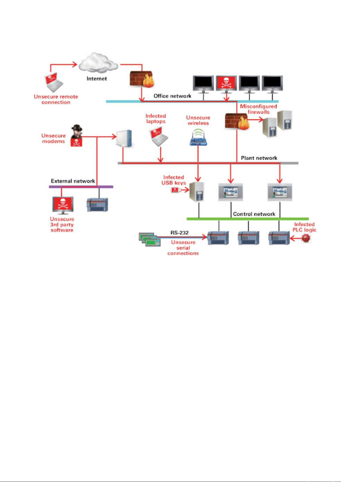
Cybersecurity considerations for electrical distribution systems
Securing the Network Management Module – 139
•
•
•
•
•
•
•
•
•
•
4.1.4.1 Paths to the control network
The paths in above figure include:
External users accessing the network through the Internet
Misconfigured firewalls
Unsecure wireless routers and wired modems
Infected laptops located elsewhere that can access the network behind the firewall
Infected USB keys and PLC logic programs
Unsecure RS-232 serial links
The most common malicious attacks come in the following forms:
Virus—a software program that spreads from one device to another, affecting operation
Trojan horse—a malicious device program that hides inside other programs and provides access to that device
Worm—a device program that spreads without user interaction and affects the stability and performance of the ICS
network
Spyware—a device program that changes the configuration of a device
4.1.5 Defense in depth
While there are differences between traditional IT systems and ICS, the fundamental concept of “defense in depth” is applicable to
both. Defense in depth is a strategy of integrating technology, people, and operations capabilities to establish variable barriers
across multiple layers of an organization. These barriers include electronic countermeasures such as firewalls, intrusion detection
software/components, and antivirus software, coupled with physical protection policies and training. Fundamentally, the barriers are
intended to reduce the probability of attacks on the network and provide mechanisms to detect “intruders.”

Cybersecurity considerations for electrical distribution systems
Securing the Network Management Module – 140
•
•
•
•
•
4.1.6 Designing for the threat vectors
4.1.6.1 Firewalls
Firewalls provide the capability to add stringent and multifaceted rules for communication between various network segments and
zones in an ICS network. They can be configured to block data from certain segments, while allowing the relevant and necessary
data through. A thorough understanding of the devices, applications, and services that are in a network will guide the appropriate
deployment and configuration of firewalls in a network. Typical types of firewalls that can be deployed in a network include:
Packet filter or boundary firewalls that work on the network layer
These firewalls mainly operate at the network layer, using pre-established rules based on port numbers and protocols
to analyze the packets going into or out of a separated network.
These firewalls either permit or deny passage based on these rules.
Host firewalls
These firewalls are software firewall solutions that protect ports and services on devices. Host firewalls can apply
rules that track, allow, or deny incoming and outgoing traffic on the device and are mainly found on mobile devices,
laptops, and desktops that can be easily connected to an ICS.
Application-level proxy firewalls
These firewalls are highly secure firewall protection methods that hide and protect individual devices and computers
in a control network. These firewalls communicate at the application layer and can provide better inspection
capabilities. Because they collect extensive log data, application-level proxy firewalls can negatively impact the
performance of an ICS network.
Stateful inspection firewalls
These firewalls work at the network, session, and application layers of the open system interconnection (OSI).
Stateful inspection firewalls are more secure than packet filter firewalls because they only allow packets belonging to
allowed sessions.
These firewalls can authenticate users when a session is established and analyze a packet to determine whether they
contain the expected payload type or enforce constraints at the application layer.
SCADA hardware firewalls
These are hardware-based firewalls that provide defense for an ICS based on observing abnormal behavior on a
device within the control network. For example, if an operator station computer suddenly attempts to program a PLC,
this activity could be blocked and an alarm could be raised to prevent serious risk to the system.
4.1.6.2 Demilitarized zones (DMZ)
Network segmentation is a key consideration in establishing secure control networks. Firewalls should be used to create DMZ by
grouping critical components and isolating them from the traditional business IT network. A three-tier architecture should be
employed at a minimum, with a DMZ between the organization’s core network and an isolated control system’s network as shown
in below figure.
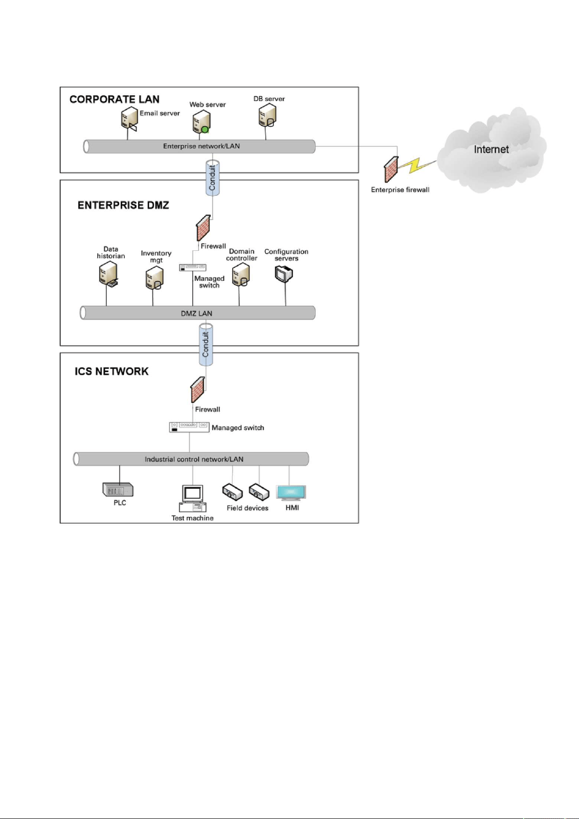
Cybersecurity considerations for electrical distribution systems
Securing the Network Management Module – 141
•
•
•
•
4.1.6.2.1 Three-tier architecture for a secure control network
Above figure shows that the control networks are divided into layers or zones based on control functions, which are then
connected by conduits (connections between the zones) that provide security controls to:
Control access to zones
Resist denial of services (DOS) attacks or the transfer of malware
Shield other network systems
Protect the integrity and the confidentiality of network traffic
Beyond network segmentation, access control (both physical and logical) should be defined and implemented.
The key consideration when designing access control is defining the required interactions both within a given zone and between
zones. These interactions should be mapped out clearly and prioritized based on need. It is important to realize that every hole
poked in a firewall and each non-essential functionality that provides access or creates additional connectivity increases potential
exposure to attacks. A system then becomes only as secure as the devices connecting to it.
If mapped correctly, the potential adverse impact to control system reliability and functionality should be negligible. However, this
element introduces additional costs (in terms of firewall and other network infrastructure) and complexity to the environment.

Cybersecurity considerations for electrical distribution systems
Securing the Network Management Module – 142
•
•
•
•
•
•
•
•
4.1.6.3 Intrusion detection and prevention systems (IDPS)
These are systems that are primarily focused on identifying possible incidents in an ICS network, logging the information about
them, attempting to stop them, and reporting them to ICS security administrators.
Because these systems are critical in an ICS network, they are regular targets for attacks and securing them is extremely important.
The type of IDPS technology deployed will vary with the type of events that need to be monitored.
There are four classes of IDPS technology:
Network-based IDPS monitors network traffic for particular ICS network segments or devices and analyzes the
network and application protocol activity to identify suspicious activity
Wireless IDPS monitors and analyzes wireless network traffic to identify suspicious activity involving the ICS wireless
network protocol
Network behavior analysis IDPS examines ICS network traffic to identify threats that generate unusual traffic flows
such as DOS attacks
Host-based IDPS monitors the characteristics and the events occurring within a single ICS network host for
suspicious activity
4.1.7 Policies, procedures, standards, and guidelines
For the defense in depth strategy to succeed, there must be well-documented and continuously reviewed policies, procedures,
standards, and guidelines.
Policies provide procedures or actions that must be carried out to meet objectives and to address the who, what, and
why
Procedures provide detailed steps to follow for operations and to address the how, where, and when
Standards typically refer to specific hardware and software, and specify uniform use and implementation of specific
technologies or parameters
Guidelines provide recommendations on a method to implement the policies, procedures, and standards
4.1.7.1 Understanding an ICS network
Creating an inventory of all the devices, applications, and services that are hosted in a network can establish an initial baseline for
what to monitor. Once those components are identified and understood, control, ownership, and operational consideration can be
developed.
4.1.7.2 Log and event management
It is important to understand what is happening within the network from both a performance and security perspective. This is
especially true in a control systems environment.
Log and event management entails monitoring infrastructure components such as routers, firewalls, and IDS/IPS, as well as
host assets. Security Information and Event Management (SIEM) systems can collect events from various sources and provide
correlation and alerts.
Generating and collecting events, or even implementing a SIEM is not sufficient by itself. Many organizations have SIEM solutions,
but alerts go unwatched or unnoticed.
Monitoring includes both the capability to monitor environments and the capacity to perform the monitoring. Capability relates to
the
design and the architecture of the environment. Has it been built in a manner that takes into consideration the ability to monitor?
Capacity speaks to the resources (personnel, tools, expertise) needed to perform meaningful interpretation of the information and
initiate timely and appropriate action.
Through monitoring, the organization can identify issues such as suspicious or malicious activities. Awareness can be raised when
new (potentially unauthorized) devices appear in the environment. Careful consideration should be taken into account to ensure that
log and event management does not adversely impact the functionality or the reliability of the control system devices.

Cybersecurity considerations for electrical distribution systems
Securing the Network Management Module – 143
•
•
•
•
•
•
•
•
•
•
•
•
•
•
•
•
•
•
4.1.7.3 Security policy and procedures
It is important to identify “asset owners,” and to develop policies and procedures for a cybersecurity program. These policies need
to be practical and enforceable in order to be effective. Policies should also address access related issues, such as physical access,
contractors, and vendors.
Existing (traditional) IT standards and policies may not apply (or have not been considered) for control systems. A gap analysis
should be performed to determine which components are not covered (or not adequately covered) by existing policies.
Relationships with existing policies and standards should be explicitly identified and new or supporting policies should be
developed. It is important that industrial control system administrators have proper authorizations and full support of their
management to implement policies that will help secure the ICS network.
4.1.7.4 ICS hardening
The goal for system hardening is to reduce as many security risks as possible by securely configuring ICS networks. The idea is to
establish configurations based on what is required and eliminate unnecessary services and applications that could potentially
provide another possible entry point to an intruder.
Minimum security baselines should be established for the various platforms and products deployed (operating system, application,
and infrastructure elements such as drives, meters, HMI devices). The following actions should be implemented where applicable:
Disable unnecessary services
Disable anonymous FTP
Do not use clear text protocols (e.g., use SSH v2 instead of Telnet)
Install only required packages/applications/features
Deploy antivirus solutions (where possible)
Disable or otherwise control use of USB devices
Establish a warning banner
Change default passwords (e.g., SNMP)
It may be easier to implement these actions on devices for which you control the base operating system platform. However,
several
of the items listed above can be configured from the product specific configuration options.
Changes such as these could potentially impact the functionality of a control system device. Extensive testing needs to be
conducted before deployment to minimize this impact.
4.1.7.5 Continuous assessment and security training
It is critical that ICS network administrators and regular users be properly trained to ensure the security of the ICS and the safety of
the people who operate and depend on it.
Ongoing vulnerability assessments are critical to identify issues and understand the effectiveness of other defensible network
elements.
Assessments should include testing and validating the following:
Monitoring capabilities and alerts are triggered and responded to as expected
Device configuration of services and applications
Expected connectivity within and between zones
Existence of previously unknown vulnerabilities in the environment
Effectiveness of patching
A program should be established for performing assessments.
The actual assessment should be performed by a qualified resource, which can be an in-house or third-party organization.
Regardless of who performs the assessments, in-house resources need to be involved in the planning, scoping, and supporting of
assessment activities and must be appropriately trained to do so.
Assessments should be conducted according to a methodology that is clearly defined to address:
Physical security
People and processes
Network security
Host security
Applications security (both internally developed and commercially off-the-shelf (COTS))

Cybersecurity considerations for electrical distribution systems
Securing the Network Management Module – 144
4.1.7.6 Patch management planning and procedures
A patching and vulnerability management process should be established based on the timely awareness of issues and appropriate
action. This process should take all of the elements that make up the control system environment into consideration.
Information resources should be identified for vulnerability and advisory information for the various components in the environment.
These should include vendor-specific sources as well as other public or commercial services that provide vulnerability advisory
information. For example, the National Vulnerability Database (NVD) provides information related to vulnerabilities identified in
general IT components, while the Industrial Control Systems Cyber Emergency Response Team (ICS-CERT) publishes advisories
specific to control systems.
A regular patch deployment schedule should be established for each component in the environment. Depending on the component,
this could range from a monthly schedule to an as-needed deployment, depending on the historical frequency of patch or
vulnerability related issues for the component or the vendor. Additionally, out-of-band or emergency patch management needs to
be
considered and qualifications need to be defined.
Vulnerability information and advisories should be reviewed regularly and assessments should be performed to determine the
relative severity and urgency of issues.
Elements of the process should also include the preparation, scheduling, and change controls; testing and rollback procedures;
and pre-deployment notification to stakeholders that includes scope, expectations, and reporting. Testing is a significant element,
as
the effect of the patch application needs to be clearly understood; unintended or unexpected impacts to a control system
component influence the decision to deploy a patch. In the event that it isdetermined that a patch cannot be safely deployed but
the severity of the issue represents a significant concern, compensating controls should be investigated.
4.1.8 Conclusion
To protect important assets, all organizations must take cybersecurity threats seriously and meet them proactively with a system-
wide defensive approach specific to organizational needs.
There is no protection method that is completely secure. A defense mechanism that is effective today may not be effective
tomorrow– the ways and means of cyber-attacks constantly change. It is critical ICS administrators remain aware of changes in
cybersecurity and continue to work to prevent any potential vulnerabilities in the systems they manage.
4.1.9 Terms and definitions
DMZA demilitarized zone is a logical or physical sub network that interfaces an organization’s external
services to a larger, untrusted network and providing an additional layer of security.
EncryptionThe process of transforming plain or clear text using analgorithm to make it unreadable to anyone
except those possessing special knowledge.
ICSA device or set of device that manage, command, direct, or regulate the behavior of other devices
or systems.
ProtocolA set of standard rules for data representation, signaling, authentication, and error detection
required to send information over a communications channel
4.1.10 Acronyms
COTSCommercially Off-the-Shelf
DMZDemilitarized Zone
DOSDenial of Service
FTPFile Transfer Protocol
HMIHuman Machine Interface
ICSIndustrial Control Systems
ICS-CERTIndustrial Control Systems - Cyber Emergency Response Team
IDPSIntrusion Detection and Prevention Systems

Cybersecurity considerations for electrical distribution systems
Securing the Network Management Module – 145
IDSIntrusion Detection Systems
IPSIntrusion Prevention Systems
ITInformation Technology
NVDNational Vulnerability Database
OSIOpen System Interconnection
PLCProgrammable Logic Controller
SCADASupervisory Control and Data Acquisition
SNMPSimple Network Management Protocol
SSHSecure Shell
SIEMSecurity Information and Event Management
USBUniversal Serial Bus
4.1.11 References
[1] Recommended Practice: Improving Industrial Control Systems Cybersecurity with Defense-In-Depth Strategies, October 2009
https://ics-cert.us-cert.gov/sites/default/files/FactSheets/NCCIC%20ICS_FactSheet_Defense_in_Depth_Strategies_S508C.pdf
[2] NIST.SP.800-82 Guide to Industrial Control Systems (ICS) Security, June 2011
http://csrc.nist.gov/publications/nistpubs/800-82/SP800-82-final.pdf
[3] NIST.SP.800-94 Guide to Intrusion Detection and Prevention Systems (IDPS), Feb 2007
http://csrc.nist.gov/publications/nistpubs/800-94/SP800-94.pdf
[4] Common Cybersecurity Vulnerabilities in Industrial Control Systems, May 2011
http://ics-cert.uscert.gov/sites/default/files/recommended_practices/DHS_Common_Cybersecurity_Vulnerabilities_ICS_2010.pdf
[5] The Tao of Network Security Monitoring, 2005 Richard Bejtlich

Cybersecurity recommended secure hardening guidelines
Securing the Network Management Module – 146
•
•
•
•
•
•
•
•
•
•
•
•
•
•
•
•
•
•
4.2 Cybersecurity recommended secure hardening guidelines
4.2.1 Introduction
This Network module has been designed with Cybersecurity as an important consideration. Number of Cybersecurity features are
now offered in the product which if implemented as per the recommendations in this section would minimize Cybersecurity risk to
the Network module. This section “secure configuration” or “hardening” guidelines provide information to the users to securely
deploy and maintain their product to adequately minimize the cybersecurity risks to their system.
Eaton is committed to minimizing the Cybersecurity risk in its products and deploys cybersecurity best practices and latest
cybersecurity technologies in its products and solutions; making them more secure, reliable and competitive for our customers.
Eaton also offers Cybersecurity Best Practices whitepapers to its customers that can be referenced at
www.eaton.com/
cybersecurity
4.2.2 Secure configuration guidelines
4.2.2.1 Asset identification and Inventory
Keeping track of all the devices in the system is a pre-requisite for effective management of Cybersecurity of a system. Ensure you
maintain an inventory of all the components in your system in a manner in which you uniquely identify each component. To
facilitate this Network module supports the following identifying information - manufacturer, type, serial number, f/w version
number, and location.
4.2.2.1.1 Network Module identification and its firmware information
It can be retrieved by navigating to
Card>>>System information
.
Identification
System name
Product
Physical name
Vendor
UUID
Part number
Serial number
Hardware version
Location
Contact
Firmware information
Firmware version
Firmware SHA
Firmware date
Firmware installation date
Firmware activation date
Bootloader version
4.2.2.1.2 Communication settings
It can be retrieved by navigating to
Settings>>>Network
LAN
Link status
MAC address
TheCOPY TO CLIPBOARDbutton will copy the information to the clipboard.

Cybersecurity recommended secure hardening guidelines
Securing the Network Management Module – 147
•
•
•
•
•
•
•
•
•
•
•
•
•
•
•
•
•
•
•
•
•
•
•
•
•
Configuration
IPV4
Status
Mode
Address
Netmask
Gateway
Domain
Mode
FQDN
Primary DNS
Secondary DNS
IPV6
Status
Mode
Addresses
4.2.2.1.3 UPS details
It can be retrieved by navigating to
Home>>>Details
Details
Name
Model
P/N
S/N
Location
FW version
4.2.2.2 Physical Protection
Industrial Control Protocols don’t offer cryptographic protections at protocol level, at physical ports and at controller mode switches
leaving them exposed to Cybersecurity risk. Physical security is an important layer of defense in such cases. Network module is
designed with the consideration that it would be deployed and operated in a physically secure location.
Physical access to cabinets and/or enclosures containing Network module and the associated system should be
restricted, monitored and logged at all times.
Physical access to the communication lines should be restricted to prevent any attempts of wiretapping, sabotage.
It’s a best practice to use metal conduits for the communication lines running between one cabinet to another
cabinet.
Attacker with unauthorized physical access to the device could cause serious disruption of the device functionality. A
combination of physical access controls to the location should be used, such as locks, card readers, and/or guards etc.
Network module supports the following physical access ports, controller mode switches and USB ports: RJ45, USB
A, USB Micro-B.Access to them need to be restricted.
Do not connect unauthorized USB device or SD card for any operation (e.g. Firmware upgrade, Configuration change
and Boot application change).
Before connecting any portable device through USB or SD card slot, scan the device for malwares and virus.
4.2.2.3
Authorization and Access Control
It is extremely important to securely configure the logical access mechanisms provided in Network module to safeguard the device
from unauthorized access. Eaton recommends that the available access control mechanisms be used properly to ensure that
TheCOPY TO CLIPBOARDbutton will copy the information to the clipboard.

Cybersecurity recommended secure hardening guidelines
Securing the Network Management Module – 148
•
•
•
•
•
•
•
•
•
•
•
•
access to the system is restricted to legitimate users only. And, such users are restricted to only the privilege levels necessary to
complete their job roles/functions.
Ensure default credentials are changed upon first login. Network module should not be commissioned for production
with Default credentials; it’s a serious Cybersecurity flaw as the default credentials are published in the manuals.
No password sharing – Make sure each user gets his/her own password for that desired functionality vs. sharing the
passwords. Security monitoring features of Network module are created with the view of each user having his/her
own unique password. Security controls will be weakened as soon as the users start sharing the password.
Restrict administrative privileges - Threat actors are increasingly focused on gaining control of legitimate credentials,
especially those associated with highly privileged accounts. Limit privileges to only those needed for a user’s duties.
Perform periodic account maintenance (remove unused accounts).
Change passwords and other system access credentials whenever there is a personnel change.
Use client certificates along with username and password as additional security measure.
Description of the User management in the Network Module:
User and profiles management: (Navigate to Settings>>>Users)
Add users
Remove users
Edit users
Password/Account/Session management: (Navigate to Settings>>>Users)
Password strength rules –Minimum length/Minimum upper case/Minimum lower case/Minimum digit/Special character
Account expiration–Number of days before the account expiration/Number of tries before blocking the account
Session expiration– No activity timeout/Session lease time
See "Default settings parameters" in the embedded help for (recommended) default values.
Additionally, it is possible to enable account expiration to force users renew their password periodically.
Default credentials: admin/admin
Thechangeof the default "admin" password is enforced at first connection.
It is also recommended to change the default "admin" user namethroughthe
Settings>>>Users
page.
Follow embedded help for instructions on how to edit a user account.
Server and client certificate configuration: (Navigate to Settings>>>Certificate)
Follow embedded help for instructions on how to configure it.
4.2.2.4
Deactivate unused features
Network module provides multiple options to upgrade firmware, change configurations, set power schedules, etc. The device also
provide multiple options to connect with the device i.e. SSH, SNMP,SMTP,HTTPS etc. Services like SNMPv1 are considered
insecure and Eaton recommends disabling all such insecure services.
It is recommended to disable unused physical ports like USB and SD card.
Disable insecure services like SNMP v1
Network Security
Network module provides network access to facilitate communication with other devices in the systems and configuration. But this
capability could open up a big security hole if it’s not configured securely.
Eaton recommends segmentation of networks into logical enclaves and restrict the communication to host-to-host paths. This helps
protect sensitive information and critical services and limits damage from network perimeter breaches. At a minimum, a utility
Industrial Control Systems network should be segmented into a three-tiered architecture (as recommended by NIST SP800-82[R3])
for better security control.
Deploy adequate network protection devices like Firewalls, Intrusion Detection / Protection devices,
Please find detailed information about various Network level protection strategies in Eaton Cybersecurity Considerations for
Electrical Distribution Systems [R1]. Use the below information for configuring the firewalls to allow needed access for Network
module to operate smoothly.

Cybersecurity recommended secure hardening guidelines
Securing the Network Management Module – 149
•
•
•
•
•
•
•
•
•
•
•
•
Navigate to
Information>>>Specifications/Technical characteristics>>>Port
to get the list of all ports and services
running on the device.
SNMP V1/SNMP V3 can be disabled or configured by navigating to
Settings>>>SNMP
.
Instructions are available in the
Contextual help>>>Settings>>>SNMP
.
4.2.2.5
Logging and Event Management
Best Practices
Eaton recommends that all remote interactive sessions are encrypted, logged, and monitored including all
administrative and maintenance activities.
Ensure that logs are backed up, retain the backups for a minimum of 3 months or as per organization’s security policy.
Perform log review at a minimum every 15 days.
Navigate to
Information>>>List of events codes
to get log information and how to export it.
4.2.2.6
Secure Maintenance
Best Practices
4.2.2.6.1 Apply Firmware updates and patches regularly
Due to increasing Cyber Attacks on Industrial Control Systems, Eaton implements a comprehensive patch and update process for
its products. Users are encouraged to maintain a consistent process to promptly monitor for fresh firmware updates, implement
patching and updates as and when required or released.
Navigate in the help to
Contextual help>>>Card>>>Administration
to get information on how to upgrade the Network
Module.
Eaton also has a robust vulnerability response process. In the event of any security vulnerability getting discovered in
its products, Eaton patches the vulnerability and releases information bulletin through its cybersecurity web site -
http://eaton.com/cybersecurity and patch through www.eaton.com/downloads.
Conduct regular Cybersecurity risk analyses of the organization /system.
Eaton has worked with third-party security firms to perform system audits, both as part of a specific customer’s deployment and
within Eaton’s own development cycle process. Eaton can provide guidance and support to your organization’s effort to perform
regular cybersecurity audits or assessments.
4.2.2.6.2 Plan for Business Continuity / Cybersecurity Disaster Recovery
It’s a Cybersecurity best practice for organizations to plan for Business continuity. Establish an OT Business Continuity plan,
periodically review and, where possible, exercise the established continuity plans. Make sure offsite backups include
Backup of the latest f/w copy of Network module. Make it a part of SOP to update the backup copy as soon as the
latest f/w is updated on Network module.
Backup of the most current configurations.
Documentation of the most current User List.
Save and store securely the current configurations of the device.
4.2.3 References
[R1]
Cybersecurity Considerations for Electrical Distribution Systems (WP152002EN):
http://www.eaton.com/ecm/groups/public/@pub/@eaton/@corp/documents/content/pct_1603172.pdf
[R2]
Cybersecurity Best Practices Checklist Reminder (WP910003EN):
http://www.cooperindustries.com/content/dam/public/powersystems/resources/library/1100_EAS/WP910003EN.pdf
[R3]
NIST SP 800-82 Rev 2, Guide to Industrial Control Systems (ICS) Security, May 2015:
https://ics-cert.us-cert.gov/Standards-and-References
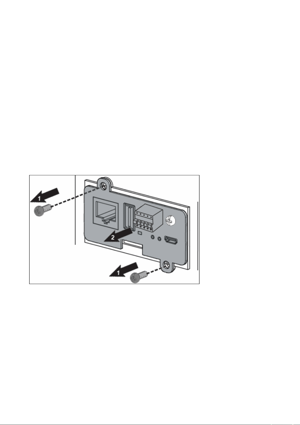
Configuring user permissions through profiles
Securing the Network Management Module – 150
[R4] National Institute of Technology (NIST) Interagency “Guidelines on Firewalls and Firewall Policy, NIST Special Publication
800-41”, October 2009:
http://nvlpubs.nist.gov/nistpubs/Legacy/SP/nistspecialpublication800-41r1.pdf
4.3 Configuring user permissions through profiles
The user profile can be defined when creating a new users or changed when modifying an existing one.
Refer to the section
Usersin the settings.
4.4 Decommissioning the Network Management module
With the increased frequency of reported data breaches, it’s becoming more and more necessary for companies to implement
effective and reliable decommissioning policies and procedures.
In order to protect the data stored on retired IT equipment from falling into the wrong hands, or a data breach, we recommend to
follow below decomissionong steps:
1- Sanitize the Network Module
Sanitizationerases all the data (user name and password, certificates, keys, settings, logs...).
To sanitize the Network Module refer to:
Sanitization
2- Unmount the Network Module from the device.
Unscrew the Network Module and remove it from the slot.

Description and features
Servicing the EMP – 151
•
•
•
•
•
•
•
•
•
•
•
•
•
•
•
•
•
5 Servicing the EMP
5.1 Description and features
The optional Environmental Monitoring Probe (EMP) enables you to collect temperature and humidity readings and monitor the
environmental data remotely.
You can also collect and retrieve the status of one or two dry contact devices (not included).
Up to 3 Environmental Monitoring Probe can be daisy chained on one device.
You can monitor readings remotely using SNMP or a standard Web browser through the Network module.
This provides greater power management control and flexible monitoring options.
The EMP device is delivered with a screw and screw anchor, magnets, nylon fasteners, tie wraps, and magnets. You can install the
device anywhere on the rack or on the wall near the rack.
The EMP has the following features:
The hot-swap feature simplifies installation by enabling you to install the probe safely without turning off power to the
device or to the loads that are connected to it.
The EMP monitors temperature and humidity information to help you protect critical equipment.
The EMP measures temperatures from 0°C to 70°C with an accuracy of ±2°C.
The EMP measures relative humidity from 10% to 90% with an accuracy of ±5%.
The EMP can be located some distance away from the device with a CAT5 network cable up to 50m (165 ft) long.
The EMP monitors the status of the two user-provided contact devices.
Temperature, humidity, and contact closure status can be displayed through a Web browserthrough the Network
module or LCD interface (if available)
A Temperature and Humidity Offset can be set.
5.2 Unpacking the EMP
The sensor will include the following:
EMPDT1H1C2 sensor
Dry contact terminal block
Quickstart
USB to RS485 converter
RJ45 female to female connector
Wall mounting screw and anchor
Rack mounting screw nut and washer
Tie wraps (x2)
Nylon fastener
For more information, refer to the device manual.
Packing materials must be disposed of in compliance with all local regulations concerning waste.
Recycling symbols are printed on the packing materials to facilitate sorting.
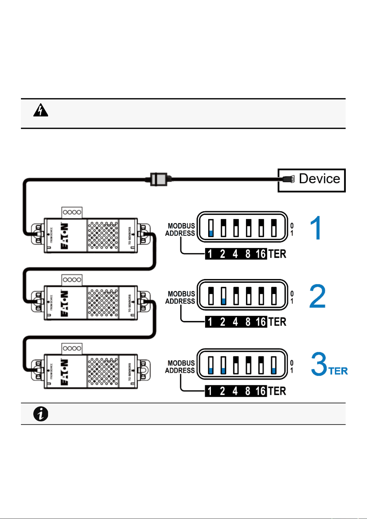
Installing the EMP
Servicing the EMP – 152
5.3 Installing the EMP
5.3.1 Defining EMPs address and termination
5.3.1.1 Manual addressing
Define
different address for all the EMPs in the daisy-chain.
Set the RS485 termination (TER) to 1 on the last EMP of the daisy chain, set it to 0 on all the other EMPs.
5.3.1.1.1 Example:manual addressing of 3 EMPs connected to the Device
5.3.2 Mounting the EMP
The EMP includes magnets, cable ties slots and keyholes to enable multiple ways of mounting it on your installation.
Address must be defined before the EMP power-up otherwise the changes won't be taken into
account.
Do not set Modbus address to 0,otherwise the EMP will not be detected.
Green LED of the TO DEVICE RJ45 connector shows if the EMP is powered by the Network module.
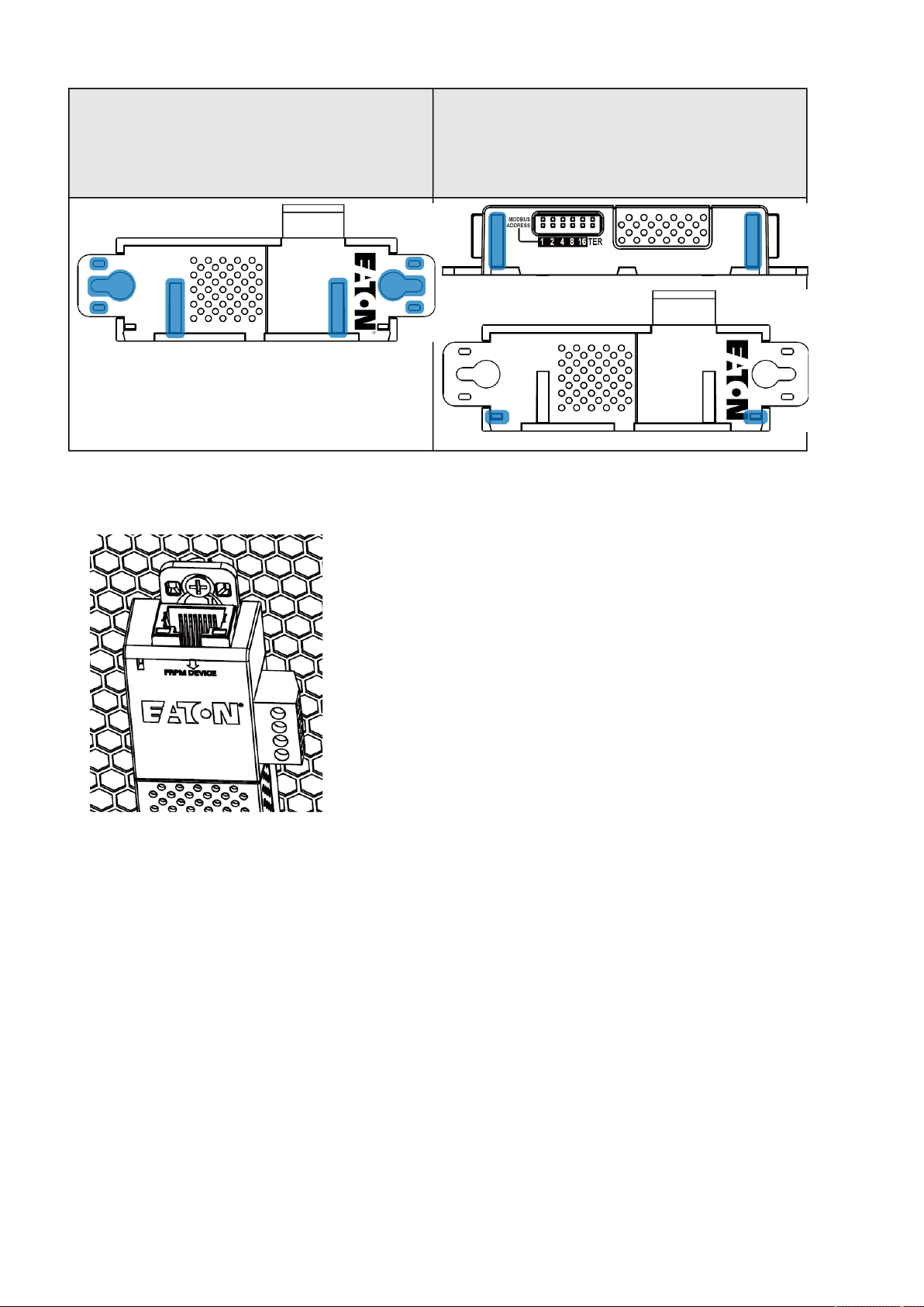
Installing the EMP
Servicing the EMP – 153
•
•
•
•
•
•
Bottom mounting capabilities:
magnets
keyholes
tie wraps
nylon fastener
Side mounting
magnets
tie wraps
5.3.2.1 Rack mounting with keyhole example
To mount the EMP on the rack, use the supplied screw, washer and nut. Then, mount the EMP on the screw and tighten it.
5.3.2.2 Rack mounting with tie wraps example
To mount the EMP on the door of the rack, use the supplied cable ties.
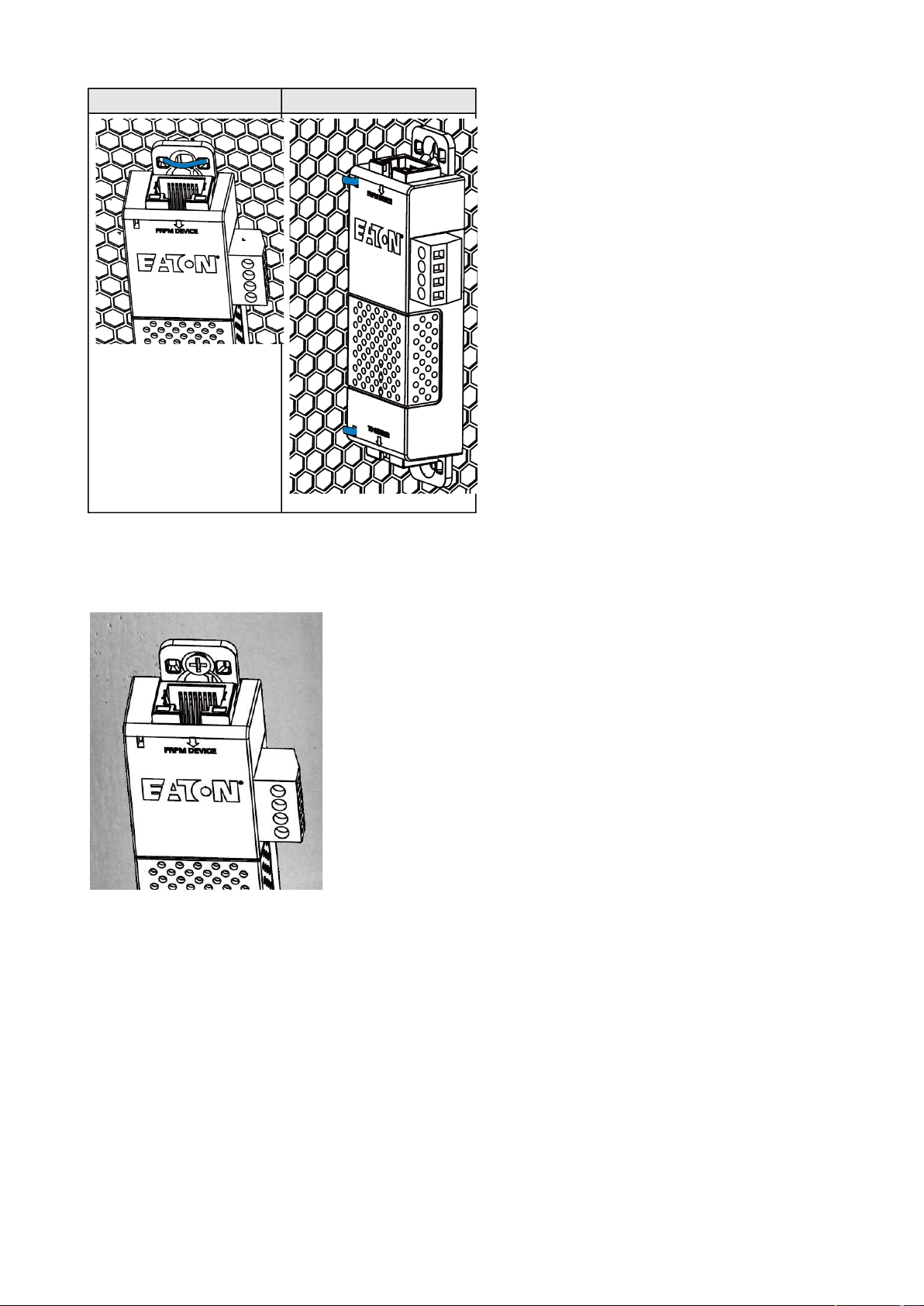
Installing the EMP
Servicing the EMP – 154
Bottom mountingSide mounting
5.3.2.3 Wall mounting with screws example
To mount the EMP on the wall close to the rack, use the supplied screw and screw anchor. Then, mount the EMP on the screw
and tighten it.
5.3.2.4 Wall mounting with nylon fastener example
To mount the EMP within the enclosure environment, attach one nylon fastener to the EMP and the other nylon fastener to an
enclosure rail post. Then, press the two nylon strips together to secure the EMP to the rail post.
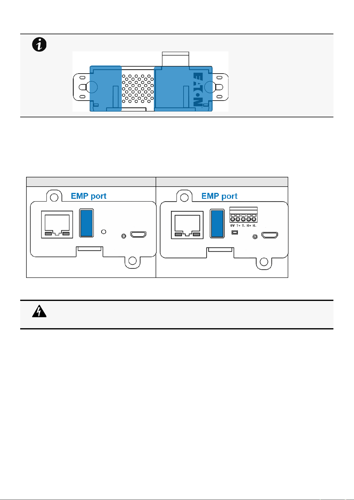
Installing the EMP
Servicing the EMP – 155
•
•
•
•
•
5.3.3 Cabling the first EMP to the device
5.3.3.1 Available Devices
5.3.3.1.1 Network-M2 and INDGW-M2
Network-M2INDGW-M2
5.3.3.2 Connecting the EMP to the device
5.3.3.2.1 Material needed:
EMP
RJ45 female/female connector (supplied in EMP accessories)
USB to RS485 converter cable(supplied in EMP accessories)
Ethernet cable (
not supplied).
Device
Cut nylon fastener and stick it on the EMP bottom on the location highlighted below, this will prevent to
interfere with the EMP data acquisition parts.
Address must be defined before the EMP power-up otherwise the changes won't be taken into
account.
Do not set Modbus address to 0,otherwise the EMP will not be detected.
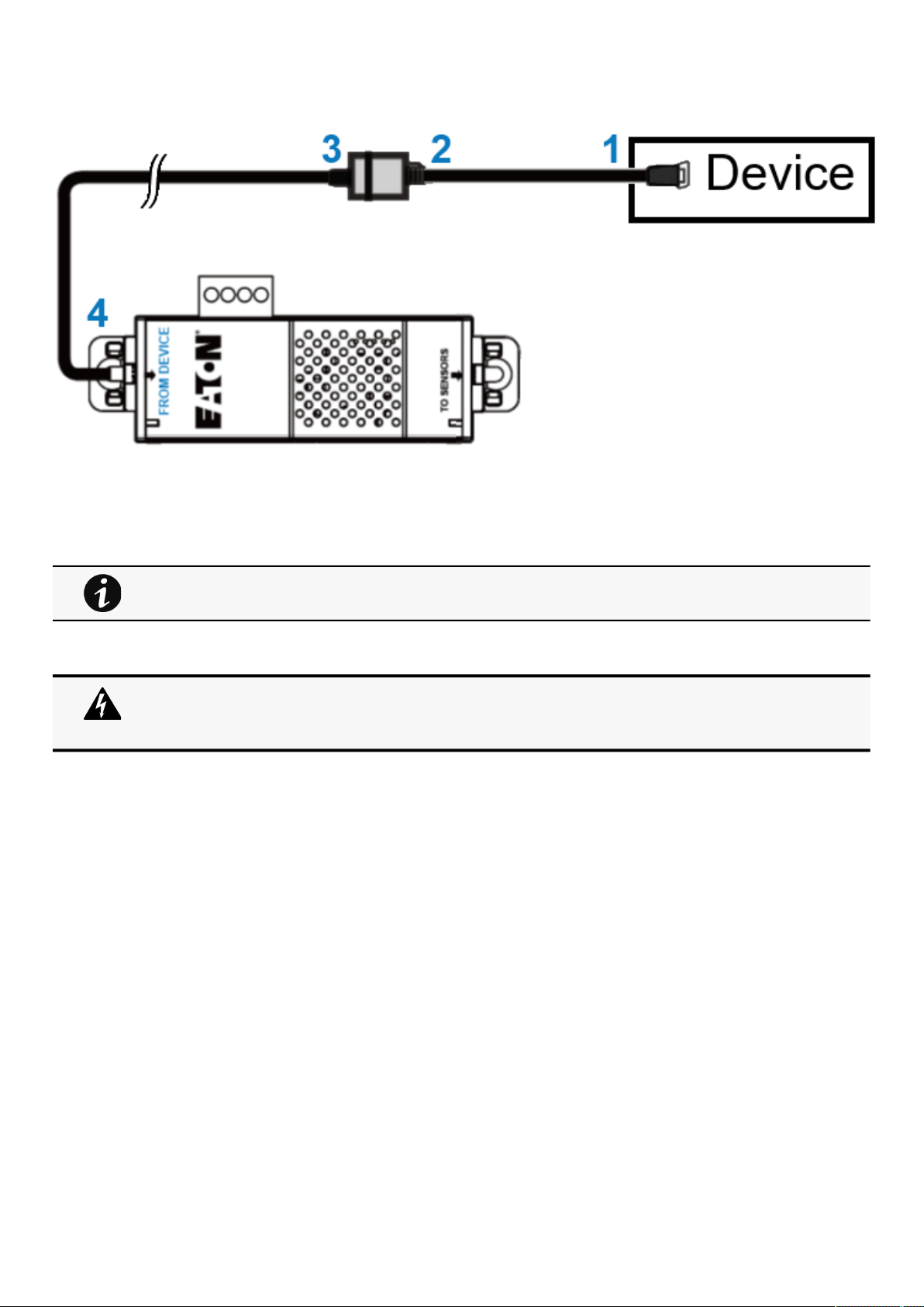
Installing the EMP
Servicing the EMP – 156
•
•
•
•
5.3.3.2.2 Connection steps
Step 1 – Connect the "USB to RS485 converter cable" to the USB port of the Device.
Step 2 – Connect the "USB to RS485 converter cable" to the RJ45 female/female connector.
Step 3 –Connect the Ethernet cableto theother end of the RJ45 female/female connector.
Step 4–Connect the other end of the Ethernet cable to the RJ-45 port on the EMP (FROM DEVICE).
5.3.4 Daisy chaining EMPs
5.3.4.1 Material needed:
First EMP connected to the device (refer to previous section)
Additional EMPs
2 x Ethernet cable (
not supplied).
Device
Use the supplied tie wraps to secure the "RS485 to USB cable" to the Network cable.
Address must be defined before the EMP power-up otherwise the changes won't be taken into
account.
Do not set Modbus address to 0,otherwise the EMP will not be detected.
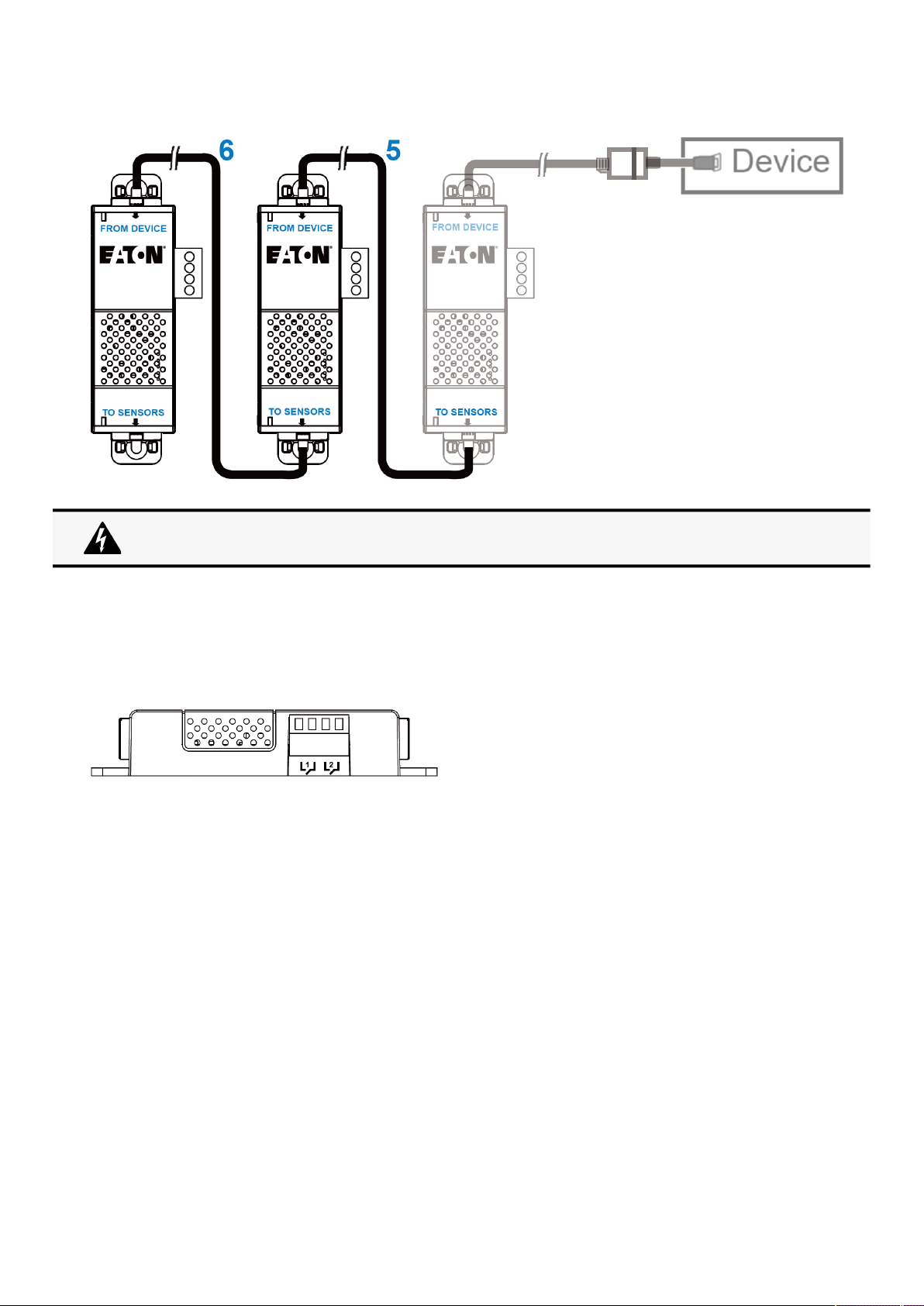
Commissioning the EMP
Servicing the EMP – 157
•
•
•
•
•
•
•
5.3.4.2 Steps
STEP 5–Connect the Ethernet cable to the "TO SENSORS" port of the first EMP, and to the "FROM DEVICE" port of the second
EMP.
STEP 6–Connect the Ethernet cable to the "TO SENSORS" port of the second EMP, and to the "FROM DEVICE" port of the third
EMP.
5.3.5 Connecting an external contact device
To connect an external device to the EMP:
1- Connect the external contact closure inputs to the terminal block on the EMP (see the table and the figure below):
External contact device 1. Connect the return and signal input wires from device 1 to screw terminals 1.
External contact device 2. Connect the return and signal input wires from device 2 to screw terminals 2.
2- Tighten the corresponding tightening screws on top of the EMP to secure the wires.
5.4 Commissioning the EMP
5.4.1 On the Network-M2 device
STEP 1:Connect to the Network Module
On a network computer, launch a supported web browser. The browser window appears.
In the Address/Location field, enter:https://xxx.xxx.xxx.xxx/where xxx.xxx.xxx.xxx is the IP address of the Network
Module.
The log in screen appears.
Enter the user name in the User Name field.
Enter the password in the Password field.
Up to 3 EMP can be daisy chained on one device.
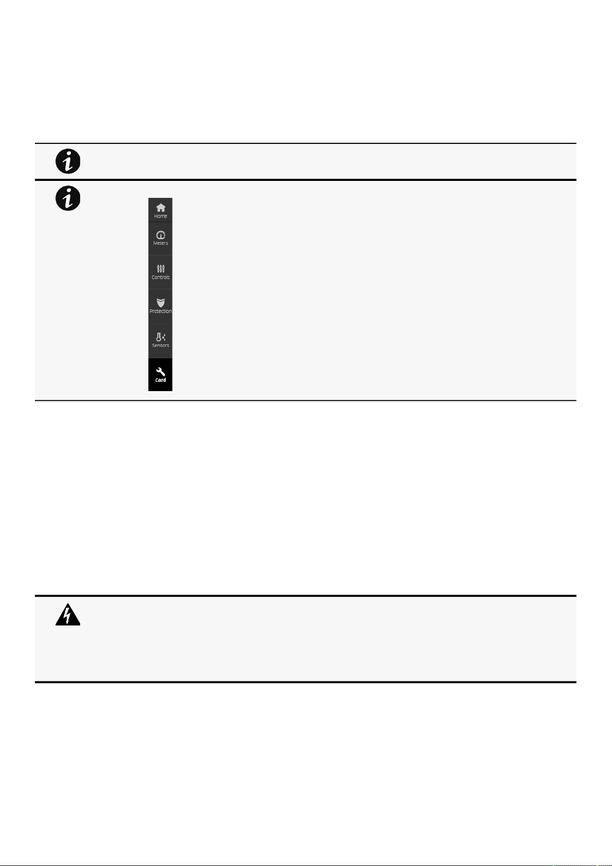
Using the EMP for temperature compensated battery charging
Servicing the EMP – 158
•
•
•
•
•
•
•
•
•
ClickSign In. The Network Module web interface appears.
STEP 2:Navigate to Cards/Commissioningpage
STEP 3: Proceed to the commissioning (refer to the contextual help for details: Cards>>>Commissioning (Sensors)
Click Discover. The EMP connected to the Network module appears in the table.
Press the pen logo to edit EMP information and access its settings.
Click Define offsets to define temperature or humidity offsets if needed.
STEP 4: Define alarm configuration (refer to the contextual help for details: Sensors>>>Alarm configuration)
Click on the Sensors menu that has just appeared on the left bar after the EMP discovery.
Select the Alarm configuration page.
Enable or disable alarms.
Define thresholds, hysteresis and severity of temperature, humidity and dry contacts alarms.
5.5 Using the EMP for temperature compensated battery
charging
This section applies only to UPS that provides temperature compensated battery charging option.
5.5.1 Addressing the EMP
Set the address 31 to the sensor dedicated to the battery room temperature:
Set all the Modbus address switches to 1 to set the EMP to the address 31 as indicated on the picture below:
When discovered, the orange LEDs of the EMP RJ45 connectors shows the data traffic.If the discovery
process fails refer to the troubleshooting section.
The Sensor button on the left bar also appears, this will be reviewed on STEP4 .
Address must be defined before the EMP is powered up; otherwise the changes won't be taken into
account.
Do not set all the Modbus address to 0,otherwise the EMP will not be detected.
Definea unique addressfor all the EMPs in the daisy-chain.
Set the RS485 termination (TER) to 1 on the last EMP of the daisy chain. On other EMPs this should be
set to 0.
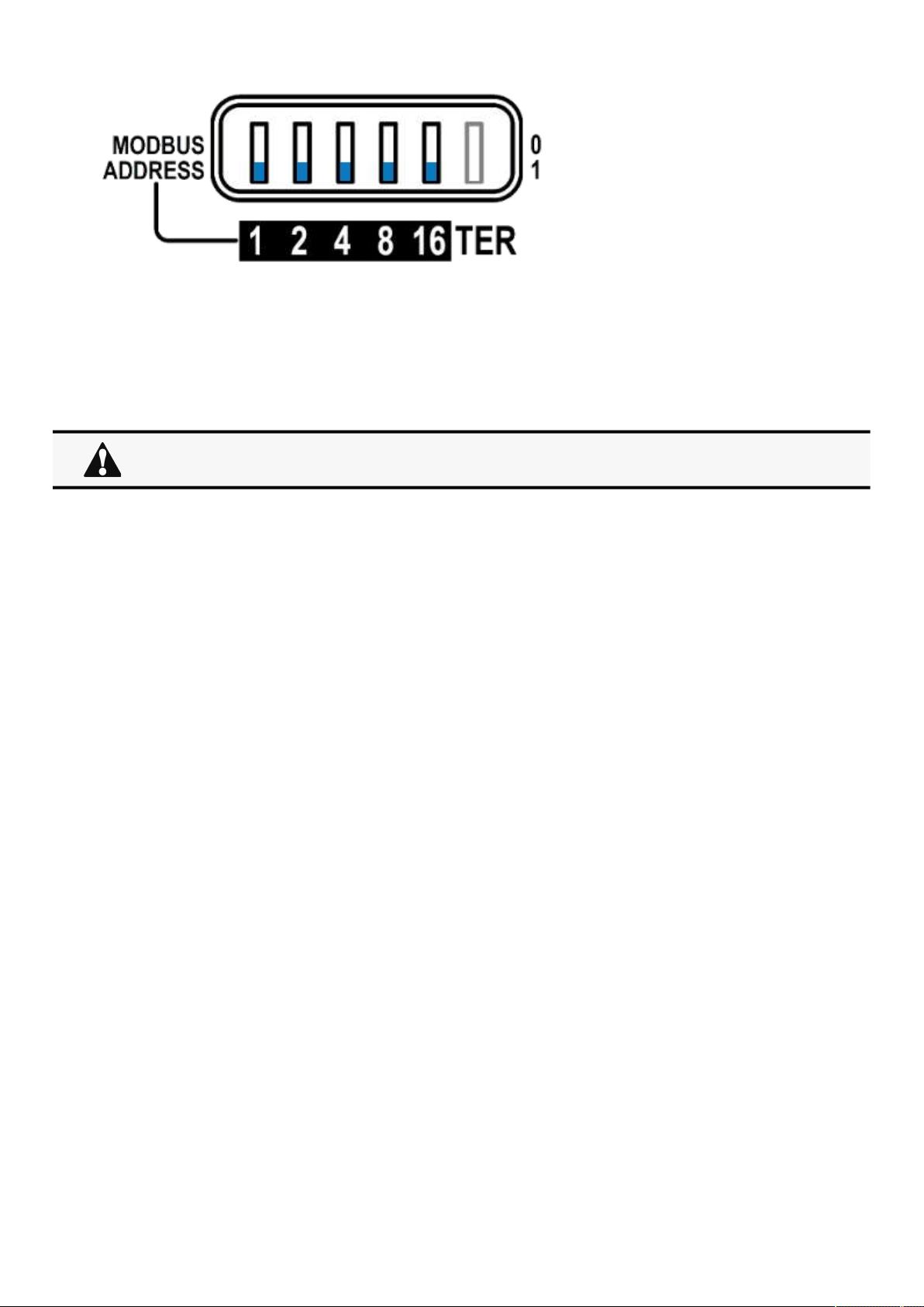
Using the EMP for temperature compensated battery charging
Servicing the EMP – 159
5.5.2 Commissioning the EMP
Refer to thesection
Commissioning the EMP.
5.5.3 Enabling temperature compensated battery charging in the UPS
To enablethe temperature compensated battery charging, refer to the UPS user manual.
The temperature compensated battery charging feature needs to be enabled in the UPS.
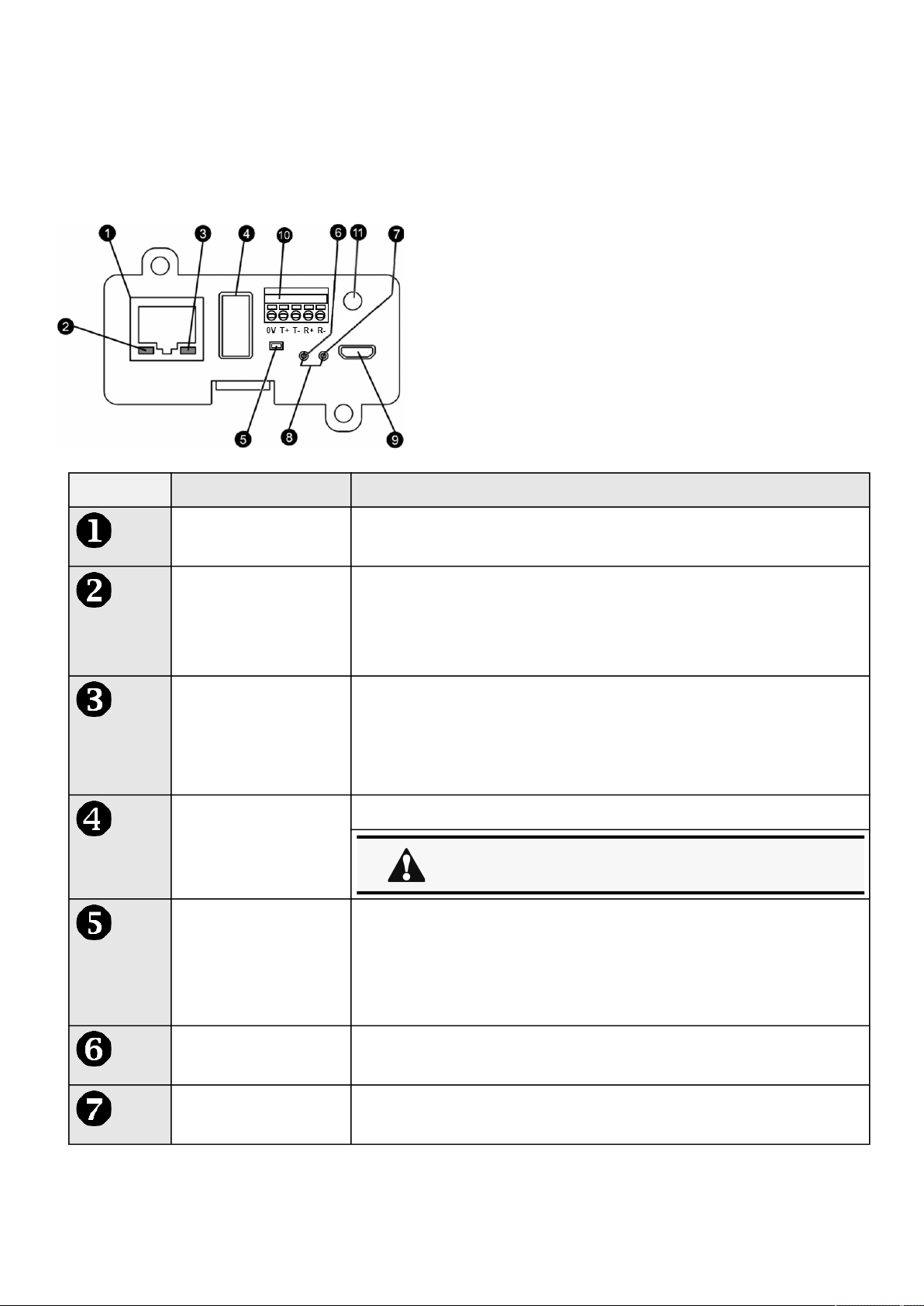
Front panel connectors and LED indicators
Information – 160
•
•
•
•
•
•
•
•
6 Information
6.1 Front panel connectors and LED indicators
NbrNameDescription
Network connectorEthernet port
Network speed LEDFlashing green sequences:
1 flash
— Port operating at 10Mbps
2 flashes — Port operating at 100Mbps
3 flashes — Port operating at 1Gbps
Network link/activity LED
Off
— UPS Network Module is not connected to the network.
Solid yellow— UPS Network Module is connected to the network, but
no activity detected.
Flashing yellow— UPS Network Module is connected to the network
and sending or receiving data.
AUX connectorFor Network Module accessories only.
Restart buttonBall point pen or equivalent will be needed to restart:
Short press (<6s)
— Safe software restart (firmware safely shutdown
before restart).
Long press (>9s)— Forced hardware restart.
ON LEDFlashing green— Network Module is operating normally.
Warning LEDSolid red— Network Module is in error state.
Do not use for general power supply or USB charger.

Default settings and possible parameters
Information – 161
Boot LEDsSolid green and flashing red— Network Module is starting boot sequence.
Settings/UPS data connectorConfiguration port.
Access to Network Module’s web interface through RNDIS (Emulated Network port).
Access to the Network Module console through Serial (Emulated Serial port).
Modbus connectorDetachable terminal block with push-in connections: 0V / T+ / T- / R+ / R-
ShieldDepending on the cabling this location may be used as a shield reference.
6.2 Default settings and possible parameters
6.2.1 Settings
6.2.1.1 General
Default settingPossible parameters
GeneralLocation—empty
Contact—empty
System name—empty
Location — 31 characters maximum
Contact— 255 characters maximum
System name— 255 characters maximum
6.2.1.2 Date & Time
Default settingPossible parameters
Date & TimeMode—Manual (Time zone: Europe/Paris)Mode—Manual (Time zone: selection on map/Date) /
Dynamic (NTP)
6.2.1.3 Users
Default settingPossible parameters
Password strengthMinimum length — enabled (8)
Minimum upper case — enabled (1)
Minimum lower case — enabled (1)
Minimum digit — enabled (1)
Special character — enabled (1)
Minimum length — enable (6-32)/disable
Minimum upper case — enable (0-32)/disable
Minimum lower case — enable (0-32)/disable
Minimum digit — enable (0-32)/disable
Special character — enable (0-32)/disable
Account expirationPassword expires after — disabled
Main administrator password never expires — disabled
Block account when invalid password is entered after
— disabled
Main administrator account never blocks — disabled
Password expires after — disable/enable (1-99999)
Main administrator password never expires — disable/
enable
Block account when invalid password is entered after —
disable/enable (1-99)
Main administrator account never blocks — disable/enable

Default settings and possible parameters
Information – 162
•
•
•
•
•
•
•
•
•
•
•
•
•
•
Session expirationNo activity timeout — 60 minutes
Session lease time — 120 minutes
No activity timeout — 1-60 minutes
Session lease time — 60-720 minutes
Local users1 user only:
Active—Yes
Profile—Administrator
Username—admin
Full Name—blank
Email—blank
Phone—blank
Organization—blank
10 users maximum:
Active—Yes/No
Profile—Administrator/Operator/Viewer
Username—255 characters maximum
Full Name—128 characters maximum
Email—128 characters maximum
Phone—64 characters maximum
Organization—128 characters maximum

Default settings and possible parameters
Information – 163
•
•
•
•
•
•
•
•
•
•
•
•
•
•
•
•
•
•
•
•
•
•
•
•
•
•
LDAPConfigure
Active – No
Security
SSL – SSL
Verify server certificate – enabled
Primary server
Name – Primary
Hostname – blank
Port – 636
Secondary server
Name – blank
Hostname – blank
Port – blank
Credentials
Anonymous search bind – disabled
Search user DN – blank
Password – blank
Search base
Search base DN –
dc=example,dc=com
Request parameters
User base DN –
ou=people,dc=example,dc=com
User name attribute – uid
UID attribute – uidNumber
Group base DN –
ou=group,dc=example,dc=com
Group name attribute – gid
GID attribute – gidNumber
Profile mapping – no mapping
Users preferences
Language –English
Temperature unit – °C (Celsius)
Date format – MM-DD-YYYY
Time format – hh:mm:ss (24h)
Configure
Active – No/yes
Security
SSL – None/Start TLS/SSL
Verify server certificate – disabled/
enabled
Primary server
Name – 128 characters maximum
Hostname – 128 characters maximum
Port – x-xxx
Secondary server
Name – 128 characters maximum
Hostname – 128 characters maximum
Port – x-xxx
Credentials
Anonymous search bind – disabled/
enabled
Search user DN – 1024 characters
maximum
Password – 128 characters maximum
Search base
Search base DN – 1024 characters
maximum
Request parameters
User base DN – 1024 characters
maximum
User name attribute – 1024 characters
maximum
UID attribute – 1024 characters maximum
Group base DN – 1024 characters
maximum
Group name attribute – 1024 characters
maximum
GID attribute – 1024 characters maximum
Profile mapping – up to 5 remote groups mapped to local
profiles, the group name must fulfil the following
conditions :
1 character minimum
255 characters maximum
First character alphanumeric or
underscore
Other characters alphanumeric,
underscore or hyphen
Users preferences
Language –German/English/Spanish/
French/Italian/Japanese/Simplified
Chinese/Traditional Chinese
Temperature unit – °C (Celsius)/°F
(Fahrenheit)
Date format – MM-DD-YYYY / YYY-MM-
DD / DD-MM-YYY / DD.MM.YYY / DD/
MM/YYY / DD MM YYYY
Time format – hh:mm:ss (24h) /
hh:mm:ss (12h)

Default settings and possible parameters
Information – 164
•
•
•
•
•
•
•
•
•
•
•
•
•
•
•
•
•
•
•
•
••
RADIUSConfigure
Active – No
Retry number – 0
Primary server
Name – blank
Secret – blank
Address – blank
UDP port – 1812
Time out – 3
Secondary server
Name – blank
Secret – blank
Address – blank
UDP port – 1812
Time out – 3
Users preferences
Language –English
Temperature unit – °C (Celsius)
Date format – MM-DD-YYYY
Time format – hh:mm:ss (24h)
Configure
Active – Yes/No
Retry number – 0 to 128
Primary server
Name – 128 characters maximum
Address – 128 characters maximum
Secret – 128 characters maximum
UDP port – 1 to 65535
Time out – 3 to 60
Secondary server
Name – 128 characters maximum
Address – 128 characters maximum
Secret – 128 characters maximum
UDP port – 1 to 65535
Time out – 3 to 60
Users preferences
Language –
German/English/Spanish/French/Italian/Japanese/
Simplified Chinese/Traditional Chinese
Temperature unit – °C (Celsius)
Date format – MM-DD-YYYY
Time format – hh:mm:ss (24h)
6.2.1.4 Network
Default settingPossible parameters
LANConfiguration — Auto negotiationConfiguration — Auto negotiation - 10Mbps -Half duplex - 10Mbps -
Full duplex - 100Mbps - Half duplex - 100Mbps -Full duplex - 1.0 Gbps
- Full duplex
IPV4Mode — Dynamic (DHCP)Mode — DHCP/Manual (IP address/Netmask/Gateway)
DomainDomain configuration (more) :
Hostname — ups-[MAC
address]
Mode — DHCP
Domain configuration (more) :
Hostname — 128 characters maximum
Mode :DHCP/Manual (Domain name/Primary DNS/
Secondary DNS)
IPV6Enable — checked
IPV6 details (more) :
Mode — Router
Enable — enable/disable
IPV6 details (more) :
Mode — Router/Manual (Address/Prefix/Gateway)
6.2.1.5 Protocols
Default settingPossible parameters
HTTPSPort — 443Port — x-xxx

Default settings and possible parameters
Information – 165
•
•
•
•
SyslogEnable — disabled
Server#1
Name – Primary
Active – No
Hostname – empty
Port – 514
Protocol – UDP
Message transfer method – Non
transparent framing
Using unicode byte order mask
(BOM)– disabled
Server#2
Name – empty
Active – No
Hostname – empty
Port – 514
Protocol – UDP
Message transfer method –
DIsabled in UDP
Using unicode byte order mask
(BOM)– disabled
Enable — disable/enable
Server#1
Name – 128 characters maximum
Active – No/Yes
Hostname – 128 characters maximum
Port – x-xxx
Protocol – UDP/TCP
Message transfer method – Non transparent framing
Using unicode byte order mask (BOM)– disable/enable
Server#2
Name – 128 characters maximum
Active – No/Yes
Hostname – 128 characters maximum
Port – x-xxx
Protocol – UDP/TCP
Message transfer method (in TCP)– Octet counting/Non
transparent framing
Using unicode byte order mask (BOM)– disable/enable
6.2.1.6 SNMP
Default settingPossible parameters

Default settings and possible parameters
Information – 166
•
•
•
•
•
•
•
•
SNMPEnable — disabled
Port — 161
SNMP V1 — disabled
Community #1 — public
Active — No
Access — Read only
Community #2 —
private
Active — No
Access — Read/Write
SNMP V3 — enabled
User #1 — readonly
Active — No
Access — Read only
Security — Auth, Priv
Authentication algorithm
— SHA256
Password — empty
Confirm password —
empty
Privacy algorithm — AES
Key — empty
Confirm key — empty
User#2 — readwrite
Active — No
Access — Read/Write
Security — Auth, Priv
Authentication algorithm
— SHA256
Password — empty
Confirmpassword —
empty
Privacy — Secured - AES
Key — empty
Confirm key — empty
Enable — disable/enable
Port — x-xxx
SNMP V1 — disable/enable
Community #1 — 128 characters maximum
Active — No/Yes
Access — Read only
Community #2 — 128 characters maximum
Active — No/Yes
Access — Read/Write
SNMP V3 — disable/enable
User #1 — 32 characters maximum
Active — No/Yes
Access — Read only/Read-Write
Security — No Auth, No Priv / Auth, No Priv / Auth,
Priv
Authentication algorithm — SHA / SHA256 / SHA384 /
SHA512
Password — 128 characters maximum
Confirm password — 128 characters maximum
Privacy algorithm — AES / AES192 / AES256
Key — 128 characters maximum
Confirm key — 128 characters maximum
User#2 — 32 characters maximum
Active — No/Yes
Access — Read only/Read-Write
Security — No Auth, No Priv / Auth, No Priv / Auth,
Priv
Authentication algorithm — SHA / SHA256 / SHA384 /
SHA512
Password — 128 characters maximum
Confirmpassword — 128 characters maximum
Privacy algorithm — AES / AES192 / AES256
Key — 128 characters maximum
Confirm key — 128 characters maximum
Trap receiversNo trapActive — No/Yes
Application name — 128 characters maximum
Hostname or IP address — 128 characters maximum
Port — x-xxx
Protocol — V1
Trap community — 128 characters maximum
6.2.1.7 Modbus
This setting is only for the Modbus Network Module INDGW-M2.

Default settings and possible parameters
Information – 167
Default settingPossible parameters
Modbus RTUEnable — disabled
Baud rate (bps) — 19200
Parity — Even
Stop bits – 1
Enable — disable/enable
Baud rate (bps) — 1200/2400/4800/9600/19200/38400/57600/115200
Parity — None/Even/Odd
Stop bits – 1/2
Modbus TCPEnable — disabled
Port — 502
Enable — disable/enable
Port — x-xxx
Mapping configurationNo mappingName – 128 characters maximum
Map – Eaton ModbusMS compatible
Transport – RTU/TCP
Device ID – from 1 to 247
Access – None/Read only/Read/Write
Illegal read behaviour – Return exception/Return zeros
6.2.1.8 Certificate
Default settingPossible parameters
Local certificatesCountry — FR
State or Province — 38
City or Locality — Grenoble
Organization name — Eaton
Organization unit — Power quality
Contact email address — blank
Country — Country code
State or Province —64 characters maximum
City or Locality —64 characters maximum
Organization name —64 characters maximum
Organization unit —64 characters maximum
Contact email address —64 characters maximum
6.2.1.9 Email
Default settingPossible parameters

Default settings and possible parameters
Information – 168
•
•
•
•
•
•
•
•
•
•
•
Email sending
configuration
No email5 configurations maximum
Active — No/Yes
Configuration name — 128 characters maximum
Email address — 128 characters maximum
Notify on events
Active — No/Yes
On card events – Subscribe/Attach logs (Critical/Warning/
Info)
On devices events– Subscribe/Attach logs (Critical/
Warning/Info)
Exceptions on events notification – Always notify events
with code/Never notify events with code
Periodic report
Active — No/Yes
Recurrence – Every day/Every week/Every month
Starting – Date and time
Topic – Subscribe/Attach logs (Card/Devices)
Email configuration
Sender – text field/list of customization key words
Subject – text field/list of customization key words
SMTPServer IP/Hostname — blank
SMTP server authentication —
disabled
Port — 25
Sender address —
Secure SMTP connection —
enabled
Verify certificate authority —
disabled
Server IP/Hostname — 128 characters maximum
SMTP server authentication — disable/enable (Username/Password — 128
characters maximum)
Port — x-xxx
Sender address — 128 characters maximum
Secure SMTP connection — enable/disable
Verify certificate authority — disable/enable
6.2.1.10 My preferences
Default settingPossible parameters
ProfileEdit user:
Full name — Administrator
Email — blank
Phone — blank
Organization — blank
Edit user:
Full name — 128 characters maximum
Email — 128 characters maximum
Phone — 64 characters maximum
Organization — 128 characters maximum
Temperature°C (Celsius)°C (Celsius)/°F (Fahrenheit)
Date formatMM-DD-YYYYMM-DD-YYYY / YYY-MM-DD / DD-MM-YYY / DD.MM.YYY / DD/MM/
YYY / DD MM YYYY
Time formathh:mm:ss (24h)hh:mm:ss (24h) / hh:mm:ss (12h)
LanguageEnglishLanguage —German/English/Spanish/French/Italian/Japanese/Simplified
Chinese/Traditional Chinese

Default settings and possible parameters
Information – 169
6.2.2 Meters
Default settingPossible parameters
ConfigurationLog measures every—60sLog measures every — 3600s maximum
6.2.3 Sensors alarm configuration
Default settingPossible parameters
TemperatureEnabled—No
Low critical – 0°C/32°F
Low warning – 10°C/50°F
High warning – 70°C/158°F
High critical – 80°C/176°F
Enabled—No/Yes
low critical<low warning<high warning<high critical
HumidityEnabled—No
Low critical – 10%
Low warning – 20%
High warning – 80%
High critical – 90%
Enabled—No/Yes
0%<low critical<low warning<high warning<high critical<100%
Dry contactsEnabled—No
Alarm severity – Warning
Enabled—No/Yes
Alarm severity – Info/Warning/Critical

Specifications/Technical characteristics
Information – 170
6.3 Specifications/Technical characteristics
Physical characteristics
Dimensions (wxdxh)132 x 66 x 42 mm | 5.2 x 2.6 x 1.65 in
Weight70 g | 0.15 lb
RoHS100% compatible
Storage
Storage temperature-25°C to 70°C (14°F to 158°F)
Ambient conditions
Operating temperature0°C to 70°C (32°F to 158°F)
Relative humidity5%-95%, noncondensing
Module performance
Module input power5V-12V ±5% | 1A
AUX output power5V ±5% | 200mA
Date/Time backupCR1220 battery coin cell | The RTC is able to keep the date and the time when Network Module is OFF
Functions
LanguagesEnglish, French, Italian, German, Spanish, Japanese,
Alarms/LogEmail, SNMP trap, web interface / Log on events
NetworkGigabit ETHERNET, 10/100/1000Mb/s, auto negotiation, HTTP 1.1, SNMP V1, SNMP V3, NTP, SMTP,
DHCP
SecurityRestricted to TLS 1.2
Supported MIBs
xUPS MIB | Standard IETF UPS MIB (RFC 1628) | Sensor MIB
BrowsersInternet Explorer, Google Chrome, Firefox, Safari
Settings (default values)
IP networkDHCP enabled | NTP server: pool.ntp.org
Port443 (https), 22 (ssh), 161 (snmp), 162 (snmp trap), 25 (smtp), 8883 (mqtts), 123 (ntp), 5353 (mdns-sd), 80
(http), 514 (syslog),636 (LDAP), 1812 (RADIUS)
Web interface access controlUser name: admin | Password: admin
Settings/UPS data connectorUSB RNDIS Apipa compatible | IP address: 169.254.0.1 | Subnet mask: 255.255.0.0
6.4 List of event codes
To get access to the Alarm log codes or the System log codes for email subscription, see the
Alarm log codesand System log
codessections.
6.5 Alarm log codes
To retrieve Alarm logs, navigate to Alarm section and press the Download alarms button.

Alarm log codes
Information – 171
6.5.1 Critical
CodeSeverityActive messageNon-active messageAdvice
002CriticalInternal failureEnd of internal failureService required
004CriticalTemperature alarmTemperature OKCheck air conditioner
007CriticalFan faultFan OKService required
00FCriticalParallel UPS not compatibleParallel UPS compatibility OKService required
010CriticalUPS power supply faultUPS power supply OKService required
011CriticalParallel UPS protection lostParallel UPS protection OKReduce output load
012CriticalParallel UPS measure inconsistentParallel UPS measure OKService required
100CriticalRectifier fuse faultRectifier fuse OKService required
105CriticalInput AC module failureInput AC module OKService required
110CriticalBuilding alarm (through dry contact)Building alarm OK-
11FCriticalBuilding alarm (through Network
module)
Building alarm OK-
202CriticalBypass thermal overloadBypass thermal OKReduce output load
203CriticalBypass temperature alarmBypass temperature OKCheck air conditioner
207CriticalBypass AC module failureBypass AC module OK-
208CriticalBypass overloadNo bypass overload-
305CriticalRectifier failureRectifier OKService required
306CriticalRectifier overloadRectifier OKReduce output load
308CriticalRectifier short circuitRectifier OKReduce output load
400CriticalDCDC converter failureDCDC converter OKService required
500CriticalBattery charger faultBattery charger OKService required
600CriticalBattery fuse faultBattery fuse OKService required
602CriticalBattery fuse faultBattery fuse OKService required
604CriticalBattery lowBattery OK-
607CriticalBattery test failedBattery test OKCheck battery
60DCriticalNo batteryBattery presentCheck battery
629CriticalBattery voltage low criticalBatteryvoltage OKCheck battery
62BCriticalBattery voltage high criticalBatteryvoltage OKCheck battery
62DCriticalBattery charge current low criticalBatterycharge current OKCheck battery
62FCriticalBatterycharge current high criticalBatterycharge current OKCheck battery
631CriticalBattery discharge current low
critical
Batterydischarge current OKCheck battery
633CriticalBatterydischarge current high
critical
Batterydischarge current OKCheck battery
635CriticalBattery temperature low criticalBatterytemperature OKCheck battery
Below codes are the one to be used to add "Exceptions on events notification" on email sending
configurations.
Some zeros maybe added in front of the code when displayed in emails or logs.

Alarm log codes
Information – 172
637CriticalBatterytemperature high criticalBattery temperature OKCheck battery
63ECriticalBattery faultBattery OKCheck battery
700CriticalInverter limitationNo current limitationReduce output load
701CriticalInverter fuse faultInverter fuse OKService required
704CriticalInverter internal failureUPS OKService required
705CriticalInverter overloadNo power overloadReduce output load
706CriticalTemperature alarmTemperature OKCheck air conditioner
70ACriticalInverter thermal overloadNo power overloadReduce output load
70BCriticalInverter short circuitEnd of inverter short circuitService required
802CriticalShutdown imminentShutdown canceled-
805CriticalOutput short circuitOutput OKReduce output load
806CriticalEmergency power OFFNo emergency OFF-
811CriticalParallel negative powerParallel power OKReduce output load
814CriticalFirmware watchdog resetFirmware watchdog OKService required
815CriticalCalibration faultCalibration OKService required
81ECriticalLoad unprotectedLoad protected-
900CriticalMaintenance bypassNot on maintenance bypass-
1201CriticalTemperature is critically low
(EMP)
Temperature is back to low
(EMP)
-
1204CriticalTemperature is critically high
(EMP)
Temperature is back to high
(EMP)
-
1211CriticalHumidity is critically low
(EMP)
Humidity is back to low
(EMP)
-
1214CriticalHumidity is critically high
(EMP)
Humidity is back to high
(EMP)
-
6.5.2 Warning
CodeSeverityActive messageNon-active messageAdvice
001WarningOn batteryNo more on battery-
00BWarningParallel UPS redundancy lostParallel UPS redundancy OKReduce output load
00EWarningParallel UPS communication lostParallel UPS communication OKService required
103WarningUtility breaker openUtility breaker closed-
104WarningInput AC frequency out of rangeInput AC frequency in range-
106WarningInput AC not presentInput AC present-
107WarningInput bad wiringInput wiring OKCheck input wiring
108WarningInput AC voltage out of range (-)Input AC voltage in range-
109WarningInput AC voltage out of range (+)Input AC voltage in range-
10AWarningInput AC unbalancedEnd of input AC unbalanced-
200WarningBypass phase out rangeBypass phase in range-
201WarningBypass not availableBypass availableService required
204WarningBypass breaker openBypass breaker closed-
205WarningBypass modeNo more on bypass-
206WarningBypass frequency out of rangeBypass frequency in range-
209WarningBypass voltage out of rangeBypass voltage in range-

Alarm log codes
Information – 173
20AWarningBypass AC over voltageEnd of bypass AC over voltage-
20BWarningBypass AC under voltageEnd of bypass AC under voltage-
20CWarningBypass bad wiringBypass wiring OKCheck bypass wiring
300WarningDC bus + too highDC bus + voltage OKService required
301WarningDC bus - too highDC bus - voltage OKService required
302WarningDC bus + too lowDC bus + voltage OKService required
303WarningDC bus - too lowDC bus - voltage OKService required
304WarningDC bus unbalancedDC bus OKService required
501WarningCharger temperature alarmCharger temperature OKService required
502WarningMax charger voltageCharger voltage OKService required
503WarningMin charger voltageCharger voltage OKService required
603WarningBattery dischargingEnd of UPS battery discharge-
605WarningBattery temperature alarmBattery temperature OKService required
606WarningBattery breaker openBattery breaker closedService required
610WarningBattery low voltageBattery voltage OKCheck battery
613WarningBattery voltage too highBattery voltage OKCheck battery
616WarningBattery voltage unbalancedBattery voltage OKCheck battery
61CWarningCommunication with battery lostCommunication with battery
recovered
Check battery
61EWarningAt least one breaker in battery is
open
All battery breakers are closedCheck battery
61FWarningBattery State Of Charge below
limit
Battery State Of Charge OK-
620WarningBattery State Of Health below limitBatteryState Of Health OKCheck battery
628WarningBattery voltage low warningBattery voltage OKCheck battery
62AWarningBattery voltage high warningBattery voltage OKCheck battery
62CWarningBatterycharge current low
warning
Batterycharge current OKCheck battery
62EWarningBatterycharge current high
warning
Batterycharge current OKCheck battery
630WarningBattery discharge current low
warning
Battery discharge current OKCheck battery
632WarningBattery discharge current high
warning
Battery discharge current OKCheck battery
634WarningBattery temperature low warningBattery temperature OKCheck battery
636WarningBatterytemperature high warningBatterytemperature OKCheck battery
638WarningBattery BMS failureBattery BMS OKCheck battery
639WarningBattery temperature unbalancedBatterytemperature OKCheck battery
63DWarningBattery warningBattery OKCheck battery
70CWarningInverter voltage too lowInverter voltage OKService required
70DWarningInverter voltage too highInverter voltage OKService required
801WarningLoad not poweredLoad powered-
803WarningOutput breaker openOutput breaker closed-
808WarningPower overloadNo power overloadReduce output load
80DWarningInternal configuration failureInternal configuration OKService required

Alarm log codes
Information – 174
80EWarningOverload pre-alarmNo overload pre-alarmReduce output load
810WarningOverload alarmNo overloadReduce output load
816WarningCompatibility failureCompatibility OKService required
817WarningOutput over currentNo output over currentReduce output load
818WarningOutput frequency out of rangeOutput frequency in rangeService required
819WarningOutput voltage too highOutput voltage OKService required
81AWarningOutput voltage too lowOutput voltage OKService required
81BWarningUPS Shutoff requestedEnd of UPS shutoff requestedService required
81DWarningLoad not poweredLoad protected-
901WarningMaintenance bypass breaker
closed
Maintenance bypass breaker open-
B00WarningEnd of warrantyEnd of warranty cleared-
B01WarningBatteries are aging. Consider
replacement
Batteries aging condition cleared-
1032WarningProtection: immediate shutdown in
progress
Protection: immediate shutdown
completed
-
1053WarningProtection: communication lost
with agent
Protection: communication
recovered with agent
-
1200WarningCommunication lost
(with EMP)
Communication recovered
(EMP)
-
1202WarningTemperature is low
(EMP)
Temperature is back to normal
(EMP)
-
1203WarningTemperature is high
(EMP)
Temperature is back to normal
(EMP)
-
1212WarningHumidity is low
(EMP)
Humidity is back to normal
(EMP)
-
1213WarningHumidity is high
(EMP)
Humidity is back to normal
(EMP)
-
6.5.3 Info
CodeSeverityActive messageNon-active messageAdvice
005InfoCommunication lost (with UPS)Communication recovered (with
UPS)
Service required
009InfoOn high efficiency / On ESS modeHigh efficiency disabled / ESS
disabled
-
013InfoUpgrading: limited communicationEnd of upgrade mode-
101InfoOn AVR (Boost)End of AVR (Boost)-
102InfoOn AVR (Buck)End of AVR (Buck)-
63CInfoBattery informationBattery OK-
A00InfoGroup 1 is OFFGroup 1 is ON-
A01InfoGroup 2 is OFFGroup 2 is ON-
A0FInfoGroup is OFFGroup is ON-
1016InfoProtection: sequential shutdown
scheduled
Protection: sequential shutdown
canceled
-
1017InfoProtection: sequential shutdown
in progress
Protection: sequential shutdown
completed
-

Alarm log codes
Information – 175
1054InfoProtection: agent is in unknown
state
Protection: agent is in service-
1055InfoProtection: agent is startingProtection: agent is in service-
1056InfoProtection: agent is stoppingProtection: agent is in service-
1057InfoProtection: agent is stoppedProtection: agent is in service-
1100InfoSchedule: shutdown date reachedSchedule: shutdown initiated-
1101InfoSchedule: restart date reachedSchedule: restart initiated-
1300InfoNo UPS connectedCommunication recovered (with
UPS)
-
1301InfoUPS not supportedCommunication recovered (with
UPS)
-
6.5.4 With settable severity
CodeSeverityActive messageNon-active messageAdvice
1221SettableContact is active
(EMP)
Contact is back to normal
(EMP)
-

System log codes
Information – 176
6.6 System log codes
6.6.1 Critical
CodeSeverityLog messageFile
0801000AlertUser account - admin password reset to defaultlogAccount.csv
0E00400CriticalThe [selfsign/PKI] signed certificate of the <service> server is not validlogSystem.csv
0A00700ErrorNetwork module file system integrity corrupted <f/w: xx.yy.zzzz>logUpdate.csv
0000D00ErrorCard reboot due to database errorlogSystem.csv
0700200ErrorFailed to start execution of script "<script description>". Client not registered. (<script
uuid>)
logSystem.csv
0700400ErrorExecution of script "<script description>" failed with return code: <script return code>.
(<script uuid>)
logSystem.csv
0700500ErrorExecution of script "<script description>" timeout! (<script uuid>)logSystem.csv
0700700AlertFailed to prepare isolated environment for script execution. Protection service startup is
aborted.
logSystem.csv
6.6.2 Warning
CodeSeverityLog messageFile
0A00200WarningNetwork module upgrade failed <f/w: xx.yy.zzzz>logUpdate.csv
0A00A00WarningNetwork module bootloader upgrade failed <f/w: xx.yy.zzzz>logUpdate.csv
0B00500WarningRTC battery cell lowlogSystem.csv
0E00200WarningNew [self/PKI] signed certificate [generated/imported] for <service> serverlogSystem.csv
0E00300WarningThe [self/PKI] signed certificate of the <service> server will expires in <X> dayslogSystem.csv
0800700WarningUser account - password expiredlogAccount.csv
0800900WarningUser account- lockedlogAccount.csv
0C00100WarningUnable to send email: Smtp server is unknownlogSystem.csv
0C00200WarningUnable to send email: Authentication method is not supportedlogSystem.csv
0C00300WarningUnable to send email: Authentication errorlogSystem.csv
0C00500WarningUnable to send email: Certificate Authority not recognizedlogSystem.csv
0C00600WarningUnable to send email: Secure connection requiredlogSystem.csv
0C00800WarningUnable to send email: Unknown errorlogSystem.csv
0C00B00WarningUnable to send email: Recipient not specifiedlogSystem.csv
To retrieve System logs, navigate to Card>>>System logs section and press theDownload System
logsbutton.
Below codes are the one to be used to add "Exceptions on events notification" on email sending
configurations.
Some zeros maybe added in front of the code when displayed in emails or logs.

System log codes
Information – 177
0F01300WarningCard reboot due to UPS FW upgradelogSystem.csv
1000F00Warning<
feature
> settings partial restorationlogSystem.csv
1001000Warning<
feature
> settings restoration errorlogSystem.csv
1000C00WarningSettings partial restorationlogSystem.csv
1000D00WarningSettings restoration errorlogSystem.csv
6.6.3 Info
CodeSeverityLog messageFile
0300D00NoticeUser action - sanitization launchedlogSystem.csv
0A00500NoticeNetwork module sanitizedlogUpdate.csv
0A00900NoticeNetwork module bootloader upgrade success <f/w: xx.yy.zzzz>logUpdate.csv
0A00B00NoticeNetwork module bootloader upgrade started <f/w: xx.yy.zzzz>logUpdate.csv
0A00C00NoticePeriodic system integrity check startedlogUpdate.csv
0B00100NoticeTime manually changedlogSystem.csv
0B00700NoticeNTP sever not available <NTP server address>logSystem.csv
0900100NoticeSession - openedlogSession.csv
0900200NoticeSession - closedlogSession.csv
0900300NoticeSession - invalid tokenlogSession.csv
0900400NoticeSession - authentication failedlogSession.csv
0300F00NoticeUser action - network module admin password reset switch activatedlogSystem.csv
0E00500Notice[Certificate authority/ Client certificate] <id> is added for <service>logSystem.csv
0E00600Notice[Certificate authority/ Client certificate] <id> is revoked for <service>logSystem.csv
0700100InfoStart execution of script "<script description>". (<script uuid>)logSystem.csv
0700300InfoExecution of script "<script description>" succeeded. (<script uuid>)logSystem.csv
0700600Info/Notice/
Error/Debug
<Script execution log message>logSystem.csv
0800100NoticeUser account - created <user account id>logAccount.csv
0800200NoticeUser account - deleted <user account id>logAccount.csv
0800400NoticeUser account - name changed <user account id>logAccount.csv
0800600NoticeUser account - password changedlogAccount.csv
0800800NoticeUser account- password reset <user account id>logAccount.csv
0800A00NoticeUser account- unlockedlogAccount.csv
0800B00NoticeUser account - activated <user account id>logAccount.csv
0800C00NoticeUser account - deactivated <user account id>logAccount.csv
0800D00NoticeUser account - password rules changedlogAccount.csv
0800E00NoticeUser account - password expiration changedlogAccount.csv
0800F00NoticeUser account - session expiration changedlogAccount.csv
0900D00Notice<user> connected into interactive CLI with session id XXXXXXlogSession.csv
0900E00Notice<user> disconnected from interactive CLI with session id XXXXXXlogSession.csv
0900F00Notice<user> doesn't have access to CLI - CLI session id XXXXXXlogSession.csv

System log codes
Information – 178
1.
0901000Notice<user> connected and executes remote command <command> into the CLI - CLI
session id XXXXXX
logSession.csv
0901100Notice<user> finished executing remote command <command> into the CLI - CLI session
id XXXXXX
logSession.csv
0901200Notice<user> connection rejected - CLI session id XXXXXXlogSession.csv
0901300Notice<user> disconnected from interactive CLI with session id XXXXXX due to session
timeout
logSession.csv
0901400Notice<user> disconnected from interactive CLI with session id XXXXXX due to concurrent
connection with session id XXXXXX
logSession.csv
0100C00NoticeSyslog is startedlogSystem.csv
0100B00NoticeSyslog is stoppinglogSystem.csv
0100D00NoticeNetwork module is bootinglogSystem.csv
0100E00NoticeNetwork module is operatinglogSystem.csv
0100F00NoticeNetwork module is starting shutdown sequencelogSystem.csv
0101000NoticeNetwork module is ending shutdown sequencelogSystem.csv
0101400NoticeNetwork module shutdown requestedlogSystem.csv
0101500NoticeNetwork module reboot requestedlogSystem.csv
0A00100InfoNetwork module upgrade success <f/w: xx.yy.zzzz>logUpdate.csv
0A00300InfoNetwork module upgrade startedlogUpdate.csv
0A00600InfoNetwork module file system integrity OK <f/w: xx.yy.zzzz>logUpdate.csv
0B00300InfoTime with NTP synchronizedlogSystem.csv
0B00600InfoTime settings changedlogSystem.csv
0B01100InfoTime reset to last known date: "date"logSystem.csv
0C00F00InfoTest email
1000100InfoSettings saving requestedlogSystem.csv
1000200Info<
feature
> settings savedlogSystem.csv
1000A00InfoSettings restoration requestedlogSystem.csv
1000E00Info<
feature
> settings restoration successlogSystem.csv
1000B00InfoSettings restoration successlogSystem.csv
0301500NoticeSanitization switch changedlogSystem.csv
0A01600NoticeMajor version downgradelogUpdate.csv
Notes:
Event with code0700600 is used within shutdown script. The severity may vary according to the event context.

SNMP traps
Information – 179
6.7 SNMP traps
6.7.1 Sensor Mib traps
This information is for reference only.
Trap oid :
.1.3.6.1.4.1.534.6.8.1.x.x.x
Trap description
.1.3.6.1.4.1.534.6.8.1.1.0.1Sent whenever the sensor count changes after a discovery or removing from the UI.
.1.3.6.1.4.1.534.6.8.1.1.0.2Sent whenever one status of each sensor connected changes.
.1.3.6.1.4.1.534.6.8.1.2.0.1Sent whenever one status of each temperature changes.
.1.3.6.1.4.1.534.6.8.1.3.0.1Sent whenever one status of each humidity changes.
.1.3.6.1.4.1.534.6.8.1.4.0.1Sent whenever one status of each digital input alarm changes.
6.7.2 Xups Mib traps
This information is for reference only.
Trap oid :
.1.3.6.1.4.1.534.1.11.4.1.0.x
Trap message at oid :
.1.3.6.1.4.1.534.1.11.3.0
.1.3.6.1.4.1.534.1.11.4.1.0.3Battery discharging
.1.3.6.1.4.1.534.1.11.4.1.0.4Battery low
.1.3.6.1.4.1.534.1.11.4.1.0.5No more on battery
.1.3.6.1.4.1.534.1.11.4.1.0.6Battery OK
.1.3.6.1.4.1.534.1.11.4.1.0.7Power overload
.1.3.6.1.4.1.534.1.11.4.1.0.8Internal failure
.1.3.6.1.4.1.534.1.11.4.1.0.10Inverter internal failure
.1.3.6.1.4.1.534.1.11.4.1.0.11Bypass mode
.1.3.6.1.4.1.534.1.11.4.1.0.12Bypass not available
.1.3.6.1.4.1.534.1.11.4.1.0.13Load not powered
.1.3.6.1.4.1.534.1.11.4.1.0.14On battery
.1.3.6.1.4.1.534.1.11.4.1.0.15Building alarm through input dry contact
.1.3.6.1.4.1.534.1.11.4.1.0.16Shutdown imminent
.1.3.6.1.4.1.534.1.11.4.1.0.17No more on bypass
.1.3.6.1.4.1.534.1.11.4.1.0.20Breaker open
.1.3.6.1.4.1.534.1.11.4.1.0.23Battery test failed
.1.3.6.1.4.1.534.1.11.4.1.0.26Communication lost
.1.3.6.1.4.1.534.1.11.4.1.0.30Sensor contact is active
.1.3.6.1.4.1.534.1.11.4.1.0.31Sensor contact back to normal
.1.3.6.1.4.1.534.1.11.4.1.0.32Parallel UPS redundancy lost
.1.3.6.1.4.1.534.1.11.4.1.0.33Temperature alarm
.1.3.6.1.4.1.534.1.11.4.1.0.34Battery charger fault
.1.3.6.1.4.1.534.1.11.4.1.0.35Fan fault
.1.3.6.1.4.1.534.1.11.4.1.0.36Fuse fault

CLI
Information – 180
•
•
Trap oid :
.1.3.6.1.4.1.534.1.11.4.1.0.x
Trap message at oid :
.1.3.6.1.4.1.534.1.11.3.0
.1.3.6.1.4.1.534.1.11.4.1.0.42Sensor temperature is below/above critical threshold
.1.3.6.1.4.1.534.1.11.4.1.0.43Sensor humidity is below/above critical threshold
.1.3.6.1.4.1.534.1.11.4.1.0.48Maintenance bypass
6.7.3 IETF Mib-2 Ups traps
This information is for reference only.
Trap oid :
.1.3.6.1.2.1.33.2.0.x
Description :
.1.3.6.1.2.1.33.2.0.1Sent whenever the UPS transfers on battery,
then sent every minutes until the UPS Comes back to AC Input.
.1.3.6.1.2.1.33.2.0.3Sent whenever an alarm appears.
The matching alarm oid is added as binded variables in the table below.
.1.3.6.1.2.1.33.2.0.4Sent whenever an alarm disappears.
The matching alarm oid is added as binded variables in the table below.
Alarm oid at :
.1.3.6.1.2.1.33.1.6.3.x
Description when trap 3Description when trap 4
.1.3.6.1.2.1.33.1.6.3.1Battery test failedBattery test OK
.1.3.6.1.2.1.33.1.6.3.2Battery dischargingEnd of UPS battery discharge
.1.3.6.1.2.1.33.1.6.3.3Low batteryBattery OK
.1.3.6.1.2.1.33.1.6.3.5Temperature alarmTemperature OK
.1.3.6.1.2.1.33.1.6.3.6Input AC not presentInput AC present
.1.3.6.1.2.1.33.1.6.3.8Power overloadNo power overload
.1.3.6.1.2.1.33.1.6.3.9Bypass modeNo more on bypass
.1.3.6.1.2.1.33.1.6.3.10Bypass not availableBypass available
.1.3.6.1.2.1.33.1.6.3.13Battery charger faultBattery charger OK
.1.3.6.1.2.1.33.1.6.3.14Not poweredPowered (Protected or Not protected)
.1.3.6.1.2.1.33.1.6.3.16Fan faultFan OK
.1.3.6.1.2.1.33.1.6.3.17Battery fuse fault
Rectifier fuse fault
Inverter fuse fault
Battery fuse OK
Rectifier fuse OK
Inverter fuse OK
.1.3.6.1.2.1.33.1.6.3.18Internal failureEnd of internal failure
.1.3.6.1.2.1.33.1.6.3.20Communication lostCommunication recovered
.1.3.6.1.2.1.33.1.6.3.23Shutdown imminentShutdown canceled
6.8 CLI
CLI can be accessed through:
SSH
Serial terminal emulation (refer to section
Servicing the Network Management Module>>>Installing the Network
Module>>>Accessing the card through serial terminal emulation).
It is intended mainly for automated configuration of the network and time settings of the network card. It can also be used for
troubleshooting and remote reboot/reset of the network interface in case the web user interface is not accessible.

CLI
Information – 181
Warning: Changing network parameters may cause the card to become unavailable remotely. If this happens it can only be
reconfigured locally through USB.
6.8.1 Commands available
You can see this list anytime by typing in the CLI:
?
6.8.2 Contextual help
You can see this help anytime by typing in the CLI:
help
CONTEXT SENSITIVE HELP
[?] - Display context sensitive help. This is either a list of possible
command completions with summaries, or the full syntax of the
current command. A subsequent repeat of this key, when a command
has been resolved, will display a detailed reference.
AUTO-COMPLETION
The following keys both perform auto-completion for the current command line.
If the command prefix is not unique then the bell will ring and a subsequent
repeat of the key will display possible completions.
[enter] - Auto-completes, syntax-checks then executes a command. If there is
a syntax error then offending part of the command line will be
highlighted and explained.
[space] - Auto-completes, or if the command is already resolved inserts a space.
MOVEMENT KEYS
[CTRL-A] - Move to the start of the line
[CTRL-E] - Move to the end of the line.
[up] - Move to the previous command line held in history.
[down] - Move to the next command line held in history.
[left] - Move the insertion point left one character.
[right] - Move the insertion point right one character.
DELETION KEYS
[CTRL-C] - Delete and abort the current line
[CTRL-D] - Delete the character to the right on the insertion point.
[CTRL-K] - Delete all the characters to the right of the insertion point.
[CTRL-U] - Delete the whole line.
[backspace] - Delete the character to the left of the insertion point.
ESCAPE SEQUENCES
!! - Substitute the last command line.
!N - Substitute the Nth command line (absolute as per 'history' command)
!-N - Substitute the command line entered N lines before (relative)

CLI
Information – 182
•
•
•
•
•
•
6.8.3 get release info
6.8.3.1 Description
Displayscertain basic information related to the firmware release.
6.8.3.2 Access
Viewer
Operator
Administrator
6.8.3.3 Help
get_release_info
-d Get current release date
-s Get current release sha1
-t Get current release time
-v Get current release version number
6.8.4 history
6.8.4.1 Description
Displaysrecentcommands executed on the card.
6.8.4.2 Access
Viewer
Operator
Administrator
6.8.4.3 Help
history
<cr> Display the current session's command line history(by default display
last 10 commands)
<Unsigned integer> Set the size of history list (zero means unbounded). Example 'history
6' display the 6 last command
6.8.5 ldap-test
6.8.5.1 Description
Ldap-test help to troubleshoot LDAP configuration issues or working issues.

CLI
Information – 183
•
6.8.5.2 Access
Administrator
6.8.5.3 Help
Usage: ldap-test <command> [OPTION]...
Test LDAP configuration.
Commands:
ldap-test -h, --help, Display help page
ldap-test --checkusername <username> [--primary|--secondary] [-v]
Check if the user can be retrieve from the LDAP server
<username> Remote username to test
--primary Force the test to use primary server (optional)
--secondary Force the test to use secondary server (optional)
-v,--verbose Print the exchanges with LDAP server (optional)
ldap-test --checkauth <username> [--primary|--secondary] [-v]
Check if remote user can login to the card
<username> Remote username to test
-p,--primary Force the test to use primary server (optional)
-s,--secondary Force the test to use secondary server (optional)
-v,--verbose Print the exchanges with LDAP server (optional)
ldap-test --checkmappedgroups [--primary|--secondary] [-v]
Check LDAP mapping
-p,--primary Force the test to use primary server (optional)
-s,--secondary Force the test to use secondary server (optional)
-v,--verbose Print the exchanges with LDAP server (optional)
Quick guide for testing:
In case of issue with LDAP configuration, we recommend to verify the
configuration using the commands in the following order:
1. Check user can be retrieve on the LDAP server
ldap-test --checkusername <username>
2. Check that your remote group are mapped to the good profile
ldap-test --checkmappedgroups
3. Check that the user can connect to the card
ldap-test --checkauth <username>
6.8.6 logout
6.8.6.1 Description
Logout the current user.

CLI
Information – 184
•
•
•
•
•
6.8.6.2 Access
Viewer
Operator
Administrator
6.8.6.3 Help
logout
<cr> logout the user
6.8.7 maintenance
6.8.7.1 Description
Creates a maintenance report file whichmaybehandedto the technical support.
6.8.7.2 Access
Administrator
6.8.7.3 Help
maintenance
<cr> Create maintenance report file.
-h, --help Display help page
6.8.8 modbus_message_display
6.8.8.1 Description
modbus_message_display restarts the server and displays Modbus message. This command allow you to verifiy that Modbus
server is working as expected.
6.8.8.2 Access
Administrator
6.8.8.3 Help
modbus_message_display
--help Restart server and display modbus message
-h Restart server and display modbus message
This section is only for the Modbus Network Module.

CLI
Information – 185
•
•
•
•
•
•
•
•
•
•
•
•
•
•
•
•
6.8.9 modbus_statistics
6.8.9.1 Description
modbus_statistics displays Modbus RTU and TCP status and server statistics:
Bus character overrun count
Bus frame error count
Bus parity error count
Buffer overrun count
Bus message count
Valid message count
CRC error count
Incoming message count
Discarded message count
Processed message count
Success returned count
Exception returned count
6.8.9.2 Access
Administrator
6.8.9.3 Help
modbus_statistics
Display modbus server statistics
-h, --help Display the help page.
-r, --reset Reset modbus server statistics.
The counter from A1.1 to A1.4 are reset only at startup of the
server.
6.8.10 netconf
6.8.10.1 Description
Tools to display or change the network configuration of the card.
6.8.10.2 Access
Viewer(read-only)
Operator (read-only)
Administrator
6.8.10.3 Help
For Viewer and Operator profiles:
This section is only for the Modbus Network Module.

CLI
Information – 186
netconf -h
Usage: netconf [OPTION]...
Display network information and change configuration.
-h, --help display help page
-l, --lan display Link status and MAC address
-4, --ipv4 display IPv4 Mode, Address, Netmask and Gateway
-6, --ipv6 display IPv6 Mode, Addresses and Gateway
-d, --domain display Domain mode, FQDN, Primary and Secondary DNS
For Administrator profile:

CLI
Information – 187
netconf -h
Usage: netconf [OPTION]...
Display network information and change configuration.
-h, --help display help page
-l, --lan display Link status and MAC address
-d, --domain display Domain mode, FQDN, Primary and Secondary DNS
-4, --ipv4 display IPv4 Mode, Address, Netmask and Gateway
-6, --ipv6 display IPv6 Mode, Addresses and Gateway
Set commands are used to modify the settings.
-s, --set-lan <link speed>
Link speed values:
auto Auto negotiation
10hf 10 Mbps - Half duplex
10ff 10 Mbps - Full duplex
100hf 100 Mbps - Half duplex
100ff 100 Mbps - Full duplex
1000ff 1.0 Gbps - Full duplex
-f, --set-domain hostname <hostname> set custom hostname
-f, --set-domain <mode>
Mode values:
- set custom Network address, Netmask and Gateway:
manual <domain name> <primary DNS> <secondary DNS>
- automatically set Domain name, Primary and Secondary DNS
dhcp
-i, --set-ipv4 <mode>
Mode values:
- set custom Network address, Netmask and Gateway
manual <network> <mask> <gateway>
- automatically set Network address, Netmask and Gateway
dhcp
-x, --set-ipv6 <status>
Status values:
- enable IPv6
enable
- disable IPv6
disable
-x, --set-ipv6 <mode>
Mode values:
- set custom Network address, Prefix and Gateway
manual <network> <prefix> <gateway>
- automatically set Network address, Prefix and Gateway
router
Examples of usage:
-> Display Link status and MAC address
netconf -l
-> Set Auto negotiation to Link
netconf --set-lan auto
-> Set custom hostname
netconf --set-domain hostname ups-00-00-00-00-00-00
-> Set Adress, Netmask and Gateway
netconf --set-ipv4 manual 192.168.0.1 255.255.255.0 192.168.0.2
-> Disable IPv6

•
6.8.10.4 Examples of usage
-> Display Link status and MAC address
netconf -l
-> Set Auto negotiation to Link
netconf -s auto
-> Set custom hostname
netconf -f hostname ups-00-00-00-00-00-00
-> Set Adress, Netmask and Gateway
netconf -i manual 192.168.0.1 255.255.255.0 192.168.0.2
-> Disable IPv6
netconf -6 disable
6.8.11 ping and ping6
6.8.11.1 Description
Ping and ping6 utilities are used to test network connection.
6.8.11.2 Access
Administrator
6.8.11.3 Help
ping
The ping utility uses the ICMP protocol's mandatory ECHO_REQUEST datagram
to elicit an ICMP ECHO_RESPONSE from a host or gateway. ECHO_REQUEST
datagrams (``pings'') have an IP and ICMP header, followed by a ``struct
timeval'' and then an arbitrary number of ``pad'' bytes used to fill out
the packet.
-c Specify the number of echo requests to be sent
-h Specify maximum number of hops
<Hostname or IP> Host name or IP address
ping6
The ping6 utility uses the ICMP protocol's mandatory ECHO_REQUEST datagram
to elicit an ICMP ECHO_RESPONSE from a host or gateway. ECHO_REQUEST
datagrams (``pings'') have an IP and ICMP header, followed by a ``struct
timeval'' and then an arbitrary number of ``pad'' bytes used to fill out
the packet.
-c Specify the number of echo requests to be sent
<IPv6 address> IPv6 address
6.8.12 reboot
6.8.12.1 Description
Tool to Reboot the card.

•
•
•
•
•
•
•
6.8.12.2 Access
Administrator
6.8.12.3 Help
Usage: reboot [OPTION]
<cr> Reboot the card
--help Display help
--withoutconfirmation Reboot the card without confirmation
6.8.13 save_configuration | restore_configuration
6.8.13.1 Description
Save_configuration and restore_configuration are using JSON format to save and restorecertain part of the configuration of the
card.
6.8.13.2 Access
Administrator
6.8.13.3 Help
save_configuration -h
save_configuration: print the card configuration in JSON format to standard output.
restore_configuration -h
restore_configuration: restore the card configuration from a JSON-formatted standard input.
6.8.13.4 Examples of usage
6.8.13.4.1 From a linux host:
Save over SSH:sshpass -p $PASSWORD ssh $USER@$CARD_ADDRESS save_configuration -p $PASSPHRASE> $FILE
Restore over SSH:cat $FILE | sshpass -p $PASSWORD ssh $USER@$CARD_ADDRESS restore_configuration -p $PASSPHRASE
6.8.13.4.2 From a Windows host:
Save over SSH:plink $USER@$CARD_ADDRESS -pw$PASSWORD -batch save_configuration -p $PASSPHRASE > $FILE
Restore over SSH: type $FILE | plink $USER@$CARD_ADDRESS -pw $PASSWORD -batch restore_configuration -p $PASSPHRASE
(Require plink tools from putty)
Where:
$USER is user name (the user shall have administrator profile)
$PASSWORD is the user password
$PASSPHRASE is any passphrase to encrypt/decrypt sensible data.
$CARD_ADDRESS is IP or hostname of the card
$FILE is a path to the JSON file (on your host computer) where the configuration is saved or restored.

•
•
•
•
•
6.8.14 sanitize
6.8.14.1 Description
Sanitize command to return card to factory reset configuration.
6.8.14.2 Access
Administrator
6.8.14.3 Help
sanitize
-h, --help Display help page
--withoutconfirmation Do factory reset of the card without confirmation
<cr> Do factory reset of the card
6.8.15 ssh-keygen
6.8.15.1 Description
Command usedfor generating the ssh keys.
6.8.15.2 Access
Administrator
6.8.15.3 Help
ssh-keygen
-h, --help Display help
<cr> Renew SSH keys
6.8.16 time
6.8.16.1 Description
Command used to displayor changetime and date.
6.8.16.2 Access
Viewer(read-only)
Operator (read-only)
Administrator
6.8.16.3 Help
For Viewer and Operator profiles:

•
time -h
Usage: time [OPTION]...
Display time and date.
-h, --help display help page
-p, --print display date and time in YYYYMMDDhhmmss format
For Administrator profile:
time -h
Usage: time [OPTION]...
Display time and date, change time and date.
-h, --help display help page
-p, --print display date and time in YYYYMMDDhhmmss format
-s, --set <mode>
Mode values:
- set date and time (format YYYYMMDDhhmmss)
manual <date and time>
- set preferred and alternate NTP servers
ntpmanual <preferred server> <alternate server>
- automatically set date and time
ntpauto
Examples of usage:
-> Set date 2017-11-08 and time 22:00
time --set manual 201711082200
-> Set preferred and alternate NTP servers
time --set ntpmanual fr.pool.ntp.org de.pool.ntp.org
6.8.16.4 Examples of usage
-> Set date 2017-11-08 and time 22:00
time --set manual 201711082200
-> Set preferred and alternate NTP servers
time --set ntpmanual fr.pool.ntp.org de.pool.ntp.org
6.8.17 traceroute and traceroute6
6.8.17.1 Description
Traceroute and traceroute6 utilities are for checking the configuration of the network.
6.8.17.2 Access
Administrator
6.8.17.3 Help
traceroute
-h Specify maximum number of hops
<Hostname or IP> Remote system to trace

•
•
•
•
•
•
•
•
1.
a.
b.
traceroute6
-h Specify maximum number of hops
<IPv6 address> IPv6 address
6.8.18 whoami
6.8.18.1 Description
whoami displays current user information:
Username
Profile
Realm
6.8.18.2 Access
Viewer
Operator
Administrator
6.8.19 email-test
6.8.19.1 Description
mail-test sends test email to troubleshoot SMTP issues.
6.8.19.2 Access
Operator
Administrator
6.8.19.3 Help
Usage: email-test <command> ...
Test SMTP configuration.
Commands:
email-test -h, --help, Display help page
email-test -r, --recipient <recipient_address>
Send test email to the
<recipient_address> Email address of the recipient
6.8.20 systeminfo_statistics
6.8.20.1 Description
Displays the following system information usage:
CPU
usage : %
upSince: date since the system started

2.
a.
b.
c.
d.
3.
a.
i.
ii.
iii.
•
•
•
•
Ram
total: MB
free: MB
used: MB
tmpfs: temporary files usage (MB)
Flash
user data
total: MB
free: MB
used: MB
6.8.20.2 Access
Viewer
Operator
Administrator
6.8.20.3 Help
systeminfo_statistics
Display systeminfo statistics
-h, --help Display the help page.
6.8.21 certificates.
6.8.21.1 Description
Allows to manage certificates through the CLI.
6.8.21.2 Access
Administrator
6.8.21.3 Help
certificates <target> <action> <service_name>
<target> :
- local
<action> :
- print: provides a given certificate detailed information.
- revoke: revokes a given certificate.
- export: returns a given certificate contents.
- import: upload a given certificate for the server CSR. This will replace
the CSR with the certificate given.
- csr: get the server CSR contents. This will create the CSR if not already
existing.
<service_name>: mqtt/syslog/webserver

•
•
•
•
•
•
•
•
•
•
•
•
6.8.21.4 Examples of usage
6.8.21.4.1 From a linux host:
printover SSH:sshpass -p $PASSWORD ssh $USER@$CARD_ADDRESS certificates local print $SERVICE_NAME
revoke over SSH:sshpass -p $PASSWORD ssh $USER@$CARD_ADDRESS certificates localrevoke $SERVICE_NAME
exportover SSH:sshpass -p $PASSWORD ssh $USER@$CARD_ADDRESS certificates localexport $SERVICE_NAME
importover SSH:cat$FILE | sshpass -p $PASSWORD ssh $USER@$CARD_ADDRESS certificates localimport $SERVICE_NAME
csr over SSH:sshpass -p $PASSWORD ssh $USER@$CARD_ADDRESS certificates localcsr mqtt
6.8.21.4.2 From a Windows host:(plink tools from putty is required)
print over SSH:plink $USER@$CARD_ADDRESS -pw$PASSWORD -batch certificates local print $SERVICE_NAME
revoke over SSH: plink $USER@$CARD_ADDRESS -pw $PASSWORD -batch certificates localrevoke $SERVICE_NAME
export over SSH:plink $USER@$CARD_ADDRESS -pw$PASSWORD -batch certificates localexport $SERVICE_NAME
import over SSH: type $FILE | plink $USER@$CARD_ADDRESS -pw $PASSWORD -batch certificates localimport
$SERVICE_NAME
csrover SSH: plink $USER@$CARD_ADDRESS -pw $PASSWORD -batch certificates localcsr mqtt
6.8.21.4.3 Where:
$USER is user name (the user shall have administrator profile)
$PASSWORD is the user password
$PASSPHRASE is any passphrase to encrypt/decrypt sensible data.
$CARD_ADDRESS is IP or hostname of the card
$FILE is a certificate file
$SERVICE_NAME is the name one of the following services : mqtt/ syslog / webserver.
6.9 Legal information
This Network Module includes software components that are either licensed under various open source license, or under a
proprietary license.
For more information, see to the legal Information link from the main user interface in the footer.
6.9.1 Availability of Source Code
The source code of open source components that are made available by their licensors may be obtained upon written express
request by contacting
[email protected].Eatonreserves the right to charge minimal administrative costs, in
compliance with the terms of the underlying open source licenses, when the situation requires.
6.9.2 Notice for Open Source Elements
This product includes software released under BSD or Apache v2 licenses, and developed by various projects, peoples and entities,
such as, but not limited to:
* the Regents of the University of California, Berkeley and its contributors,
* the OpenEvidence Project,
* Oracle and/or its affiliates,
* Mike Bostock,
* JS Foundation and other contributors,
* 2011-2014 Novus Partners, Inc.
This product includes software developed by the OpenSSL Project for use in the OpenSSL Toolkit. (
www.openssl.org/).
This product includes cryptographic software written by Eric Young ([email protected]).

•
•
•
•
•
•
•
•
•
•
•
•
•
•
•
•
•
•
This product includes software released under MIT license, and developed by various projects, peoples and entities, such as, but
not limited to:
* Google, Inc.,
* the AngularUI Team
* Lucas Galfasó
* nerv
* Angular
* Konstantin Skipor
* Filippo Oretti, Dario Andrei
* The angular-translate team and Pascal Precht,
* Twitter, Inc.
* Zeno Rocha
* Kristopher Michael Kowal and contributors
* JS Foundation and other contributors
* Jonathan Hieb
* Mike Grabski
* Sachin N.
This product includes contents released under Creative Commons Attribution 4.0, Creative Commons Attribution-ShareAlike 3.0
Unported and SIL Open Font License licenses, and created by:
* IcoMoon
* Dave Gandy
* Stephen Hutchings and the Typicons team.
In order to access the complete and up to date copyright information, licenses, and legal disclaimers, see the Legal Information
pages, available from the HTML user interface of the present product.
6.9.3 Notice for our proprietary (i.e. non-Open source) elements
Copyright © 2019 Eaton. This firmware is confidential and licensed under Eaton Proprietary License (EPL or EULA).
This firmware is not authorized to be used, duplicated, or disclosed to anyone without the prior written permission of Eaton.
Limitations, restrictions and exclusions of the Eaton applicable standard terms and conditions, such as its EPL and EULA, apply.

6.10 Acronyms and abbreviations
AC:Alternating current.
AVR:Automatic Voltage Regulation provides stable voltage to keep equipment running in the optimal range.
BMS: A Battery Management System is any electronic system that manages li-ion battery.
bps: bit per second
BOM:In Syslog,placing an encoded Byte Order Markat the start of a text stream can indicates that the text is Unicode and identify
the encoding scheme used.
CA: Certificate Authority
CLI: Command Line Interface.
Aim is to interact with the Network Module by using commandsin the form of successive lines of text (command lines).
CSR: Certificate Signing Request
DC:Direct current.
DN:Distinguished Name (LDAP).
DHCPv6: The Dynamic Host Configuration Protocol version 6 is a network protocol for configuring Internet Protocol version 6 (IPv6)
hosts with IP addresses, IP prefixes and other configuration data required to operate in an IPv6 network.
It is the IPv6 equivalent of the Dynamic Host Configuration Protocol for IPv4.
DNS: The Domain Name System is a hierarchical decentralized naming system for computers, services, or other resources
connected to the Internet or a private network.
DST: The daylight saving time.EMP: Environmental monitoring probeGID: Group Identifier is a numeric value used to represent a
specific group (LDAP).HTTPS:HTTPS consists of communication over Hypertext Transfer Protocol (HTTP) within a connection
encrypted by Transport Layer Security (TLS).
IPP:Intelligent Power Protector is a web-based application that enables administrators to manage an UPS from a browser-based
management console. Administrators can monitor, manage, and control a single UPS locally and remotely. A familiar browser
interface provides secure access to the UPS Administrator Software and UPS Client Software from anywhere on the network.
Administrators may configure power failure settings and define UPS load segments for maximum uptime of critical servers.The
UPS can also be configured to extend runtimes for critical devices during utility power failures. For most UPSs, the receptacles on
the rear panel are divided into one or more groups, called load segments, which can be controlled independently. By shutting down
a load segment that is connected to less critical equipment, the runtime for more critical equipment is extended, providing
additional protection.
IPv4:Internet Protocol version 4 is the fourth version of the Internet Protocol (IP).
IPv6:Internet Protocol version 6 is the most recent version of the Internet Protocol (IP).
JSON:JavaScript Object Notation is an open-standard file format that uses human-readable text to transmit data objects consisting
of attribute–value pairs and array data types.
kVA:kilovolt-ampere
LAN:A LAN is a local area network, a computer network covering a small local area, such as a home or office.
LDAP:The Lightweight Directory Access Protocol is an industry standard application protocol for accessing and maintaining
distributed directory information services over an Internet Protocol.
MAC:A media access control address of a computer is a unique identifier assigned to network interfaces for communications at
the data link layer of a network segment.
MIB:A management information base is a database used for managing the entities in a communication network. Most often
associated with the Simple Network Management Protocol (SNMP).
NTP:Network Time Protocol is a networking protocol for clock synchronization between computer systems.
P/N:Part number.
RTC:Real time clock
RTU: Remote Terminal Unit
S/N:Serial number.
SMTP:Simple Mail Transfer Protocol is an Internet standard for electronic mail (email) transmission.

SNMP:Simple Network Management Protocol is an Internet-standard protocol for collecting and organizing information about
managed devices on IP networks and for modifying that information to change device behavior.
SSH:Secure Shell is a cryptographic network protocol for operating network services securely over an unsecured network.
SSL:Secure Sockets Layer, is a cryptographic protocol used for network traffic.
TCP: Transmission Control Protocol
TLS:Transport Layer Security is cryptographic protocol that provide communications security over a computer network.
TFTP:Trivial File Transfer Protocol is a simple lockstep File Transfer Protocol which allows a client to get a file from or put a file onto
a remote host.
UID:User identifier (LDAP).
UTC:Coordinated Universal Time is the primary time standard by which the world regulates clocks and time.
UPS:An uninterruptible power supply is an electrical apparatus that provides emergency power to a load when the input power
source or mains power fails.
A UPS is typically used to protect hardware such as computers, data centers, telecommunication equipment or other electrical
equipment where an unexpected power disruption could cause injuries, fatalities, serious business disruption or data loss.


7 Troubleshooting
7.1 Action not allowed in Control/Schedule/Power outage policy
7.1.1 Symptom
Below message is displayed when you access the Control, Schedule or Power outage policy page.
7.1.2 Possible Cause
1- Remote commands are not allowed due to the UPS configuration (see the action below)
2- The UPS does not support remote commands.
7.1.3 Action
Refer to the UPS user manual and its instruction on how to configure the UPS settings and allow remote commands.
Example: UPS menu Settings>>>ON/OFF settings>>>Remote command>>>Enable.
7.2 Client server is not restarting
7.2.1 Symptom
Utility power has been restored, the UPS and its load segments are powered on, but the Client server does not restart.
7.2.2 Possible Cause
The “Automatic Power ON” server setup setting might be disabled.
7.2.3 Action
In the server system BIOS, change the setting for Automatic Power ON to "Enabled".
7.3 EMP detection fails at discovery stage
In the Network Module,in Card>>>Commissioning, EMPs are missing in the Sensor commissioning table.
7.3.1 Symptom #1
The EMPs green RJ45 LED (FROM DEVICE) is not ON.
7.3.1.1 Possible causes
The EMPs are not powered by the Network module.

•
•
7.3.1.2 Action #1-1
Launch again the discovery, if it is still not ok, go to Action #1-2.
7.3.1.3 Action #1-2
1- Check the EMPs connection and cables.
Refer to the sections
Servicing the EMP>>>Installing the EMP>>>Cabling the first EMP to the deviceandServicing the
EMP>>>Installing the EMP>>>Daisy chaining 3 EMPs.
2- Disconnect and reconnect the USB to RS485 cable.
3-Launch the discovery, if it is still not ok, go to Action #1-3.
7.3.1.4 Action #1-3
1- Reboot the Network module.
2-Launch the discovery.
7.3.2 Symptom #2
The EMPs orange RJ45 LEDs are not blinking.
7.3.2.1 Possible causes
C#1: the EMP address switches are all set to 0.
C#2: the EMPs are daisy chained, the Modbus address is the same on the missing EMPs.
7.3.2.2 Action #2-1
1- Change the address of the EMPs to have different address and avoid all switches to 0.
Refer to the section
Servicing the EMP>>>Defining EMPs address and termination>>>Manual addressing.
2- Disconnect and reconnect the USB to RS485 cable. The address change is only taken into account after an EMP power-up.
3-Launch the discovery,if it is still not ok, go to Action #2-2.
7.3.2.3 Action #2-2
1- Reboot the Network module.
Refer to the section
Card>>>Administration>>>Reboot.
2-Launch the discovery.
7.4 How do I log in if I forgot my password?
7.4.1 Action
Askyour administrator for password initialization.
If you are the mainadministrator, yourpasswordcan be reset manually by following steps described in the
Recoverin
g main administrator password.

•
•
•
•
•
•
•
•
•
7.5 Card wrong timestamp leads to "Full acquisition has failed"
error message on IPM/IPP
7.5.1 Symptoms:
IPM/IPP shows the error message"The full data acquisition has failed" even if the credentials are correct.
7.5.2 Possible cause:
The Network module timestamp is not correct.
Probably the MQTT certificate is not valid at Network-M2 date.
7.5.3 Action:
Set the right date, time and timezone. If possible, use a NTP server
7.6 IPP/IPM is not able to communicate with the Network
module
7.6.1 Symptoms
In the Network Module,in Protection>>>Agents list>>>Agents list, agent is showing "
Lost" as a status.
In the Network Module,in Settings>>>Certificates>>>Trusted remote certificates, the status of theProtected
applications (MQTT) is showing"Not valid yet".
IPP/IPM shows "The authentication has failed", "The notifications reception encountered error".
7.6.2 Possible cause
The IPP/IPM certificate is not yet valid for the Network Module.
Certificates of IPP/IPM and the Network Module are not matching so that authentication and encryption of connections between
the Network Module and the shutdown agents is not working.
7.6.3 Setup
IPP/IPM is started.
Network module is connected to the UPS and to the network.
7.6.4 Action #1
Check if the IPP/IPM certificate validity for the Network Module.
STEP 1:Connect to the Network Module
On a network computer, launch a supported web browser. The browser window appears.
In the Address/Location field, enter:https://xxx.xxx.xxx.xxx/where xxx.xxx.xxx.xxx is the static IP address of the
Network Module.
The log in screen appears.
Enter the user name in the User Name field.
Enter the password in the Password field.
ClickSign In. The Network Module web interface appears.
STEP 2:Navigate toSettings/Certificatespage

•
•
•
•
•
•
•
•
•
STEP 3:In theTrusted remote certificatessection, check the status of theProtected applications (MQTT).
If it is "Valid"go to Action#2 STEP 2, if it is "Not yet valid", time of the need to be synchronized with IPP/IPM.
STEP 4:Synchronize the time of the Network Module with IPP/IPM and check that the status of theProtected applications
(MQTT)is now valid.
Communication will then recover, if notgo to Action#2 STEP 2.
7.6.5 Action #2
Pair agent to the Network Module with automatic acceptance (recommended in case the installation is done in a secure and trusted
network).
STEP 1:Connect to the Network Module.
On a network computer, launch a supported web browser. The browser window appears.
In the Address/Location field, enter:https://xxx.xxx.xxx.xxx/where xxx.xxx.xxx.xxx is the static IP address of the
Network Module.
The log in screen appears.
Enter the user name in the User Name field.
Enter the password in the Password field.
ClickSign In. The Network Module web interface appears.
STEP 2:Navigate toProtection/Agents listpage.
STEP 3:In thePairing with shutdown agentssection, select the time to accept new agents and press theStartbutton
andContinue. During the selected timeframe, new agent connections to the Network Module are automatically trusted and
accepted.
STEP 4:Action on the agent(IPP/IPM)while the time to accepts new agents is running on the Network Module
Remove theNetwork module certificate file(s) *.0that is (are) located in the folderEaton\IntelligentPowerProtector\configs\tls.
7.7 LDAP configuration/commissioning is not working
Refer to the section
Servicing the Network Management Module>>>Commissioning/Testing LDAP.
7.8 Modbus communication doesn't work
7.8.1 Symptoms
Communication doesn't work
7.8.2 Possible cause
Incorrect communication parameters.
Verify that the communication parameters are set to the desired settings.
For Modbus RTU configuration refer to the section
Contextual help>>>Settings>>>Modbus RTU.
For Modbus TCP configuration refer to the sectionContextual help>>>Settings>>>Modbus TCP.
RS-485 communication lines are reversed
For manual pairing (maximum security), go toServicing the Network Management Module>>>Pairing
agent to the Network Modulesection and then go to STEP 2, item 1.
Refer to the section Servicing the Network Management Module>>>Configuring/testing Modbus TCP
and RTU to get configuration and testings information.

•
For two-wire networks refer to the section Installing the Network Module>>>Wiring the RS-485 Modbus RTU
terminal>>>Two-wire networks.
For four-wire networks refer to the section Installing the Network Module>>>Wiring the RS-485 Modbus RTU
terminal>>>Four-wire networks.
If the Modbus Card is the last device installed in the network chain or the length of the network cable is excessive,
termination needs to be enabled.
Verify the termination settings and refer to the sectionInstalling the Network Module>>>Wiring the RS-485 Modbus
RTU terminal>>>Configuring the termination.

7.9 Password change in My preferences is not working
7.9.1 Symptoms
The password change shows "
Invalid credentials
" when I try to change my password in My preferences menu.
7.9.2 Possible cause
The password has already been changed once within a day period.
7.9.3 Action
Let one day between your last password change and retry.
7.10 SNMPv3 password management issue with Save and
Restore
7.10.1 Affected FW versions
This issue affects SNMP
configuration done on versions prior to 1.7.0 when applied to versions 1.7.0 or above.
7.10.2 Symptom
SNMPv3 connectivity is not properly working after a restore settings on a 1.7.0 version or above.
7.10.3 Cause
The SNMPv3 was
configured prior to 1.7.0.
In that case, SNMPv3 configuration is not well managed by the Save and by the Restore settings.
7.10.4 Action
Reconfigure your SNMPv3 users and passwords on versions 1.7.0 or above and Save the settings.
The SNMPv3 configuration can then be Restored.
7.11 The Network Module fails to boot after upgrading the
firmware
7.11.1 Possible Cause
The IP address has changed.
Note: If theapplication is corrupt, due to an interruptionwhile flashing the firmware for example, the boot will be done on previous
firmware.
7.11.2 Action
Recover the IP address and connect to the card.

•
•
7.12 Web user interface is not up to date after a FW upgrade
7.12.1 Symptom
After an upgrade:
The Web interface is not up to date
New features of the new FW are not displayed
7.12.1.1 Possible causes
The browser is displaying the Web interface through the cache that contains previous FW data.
7.12.1.2 Action
Empty the cache of your browser using F5 or CTRL+F5.

