(IEC 19-inch & ETSI 21-inch Cabinet)
5 U Quick Installation Guide
This document applies to the installation of the NetEngine 8000 M14,
PTN 6900-2-M14, and NE40E-X2-M14.
Issue:01
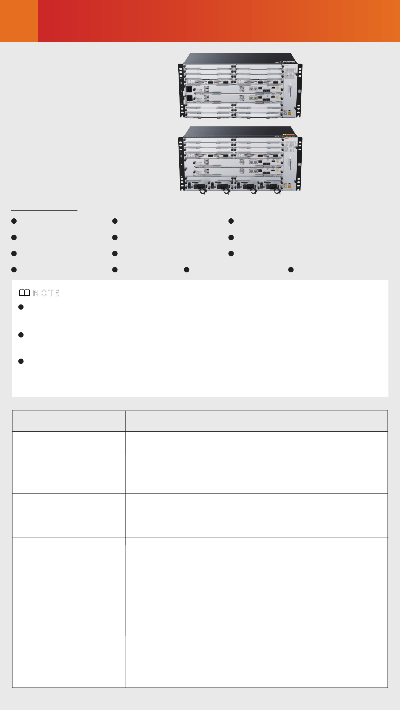
Device Overview
1
DC chassis
AC chassis
Insulation tape Corrugated pipe
ESD wrist strap
Signal cable label Cable management framePanel screw (M6x12)
Label cable tie
Floating nut (M6)
Cable tie (300 x 3.6 mm)
Power cable label
Quick Installation Guide
Serial cable
Fiber binding tape
Packing list
DC and AC Chassis are installed in the same way, and DC Chassis is
used as an example here.
Figures in the document are for reference only and may be dierent
from actual devices.
The type and quantity of items in an installation accessory package
vary according to the device model. Check the delivered items
against the actual packing list.
NOTE
Item
Chassis height[U]
Rated input
voltage[V]
Input voltage
range [V]
Maximum input
current [A]
DC Chassis
5 U
222 mm x 442 mm x
220 mm (8.74 in. x
17.4 in. x 8.66 in.)
10.1 kg (22.27 lb)
-48 V/-60 V
AC Chassis
5 U
222 mm x 442 mm x 220
mm (8.74 in. x 17.4 in. x
8.66 in.)
14.6 kg (32.19 lb)
PTN devices: 110 V/220 V
Other devices: 200 V to 240 V
/100 Vto 127 V dual live wires,
support 240V HVDC
Dimensions without
packaging(H x W x
D)[mm(in.)]
Weight without
packaging (base
configuration)[kg(lb)]
-40 V to -72 V
NetEngine 8000 M14/
PTN 6900-2-M14/
NE40E-X2-M14: 60 A
NetEngine 8000 M14/
PTN 6900-2-M14/NE40E
-X2-M14: 10 A
90 V to 290 V
Safety Guidelines
2
Observe all safety regulations and precautions
Only trained and qualified personnel are allowed to install, operate
or maintain the equipment. Familiarize yourself with all safety pre-
cautions before performing any operation on the equipment.
Operator qualifications
To ensure personal and equipment safety, observe all the safety
precautions on the equipmentand in this document.
and and items do not cover all the safety precautions and
are only supplementary to the safety precautions.
Follow all the safety precautions and instructions provided by Huawei.
The safety precautions outlined in this document are only requirements
of Huawei and do not cover general safety regulations. Huawei is not
liable for any consequence that results from violation of regulation
spertaining to safe operations or safety codes pertaining to design,
production, and equipment use.
DANGER
WARNING
CAUTION
NOTICE
Do not install or remove the equipment or power cables while power is on.
To ensure equipment and personal safety, ground the equipment before
powering it on.
DANGER
Use multiple persons to move or lift a chassis and take measures to pro-
tect personal safety.
Laser beams will cause eye damage. Do not look into bores of optical
modules or opticalfibers without eye protection.
WARNING
During equipment transport and installation, prevent the equipment
from colliding withobjects like doors, walls, or shelves.
Move an unpacked chassis upright. Do not drag it with it lying down.
Do not touch unpainted surfaces of the equipment with wet or contami-
nated gloves.
Do not open the ESD bags of cards and modules until they are delivered
to the equipmentroom. When taking a card out of the ESD bag, do not
use the connector to support the card's weight because this operation
will distort the connector and make the pins on the backplane connector
bend.
NOTICE
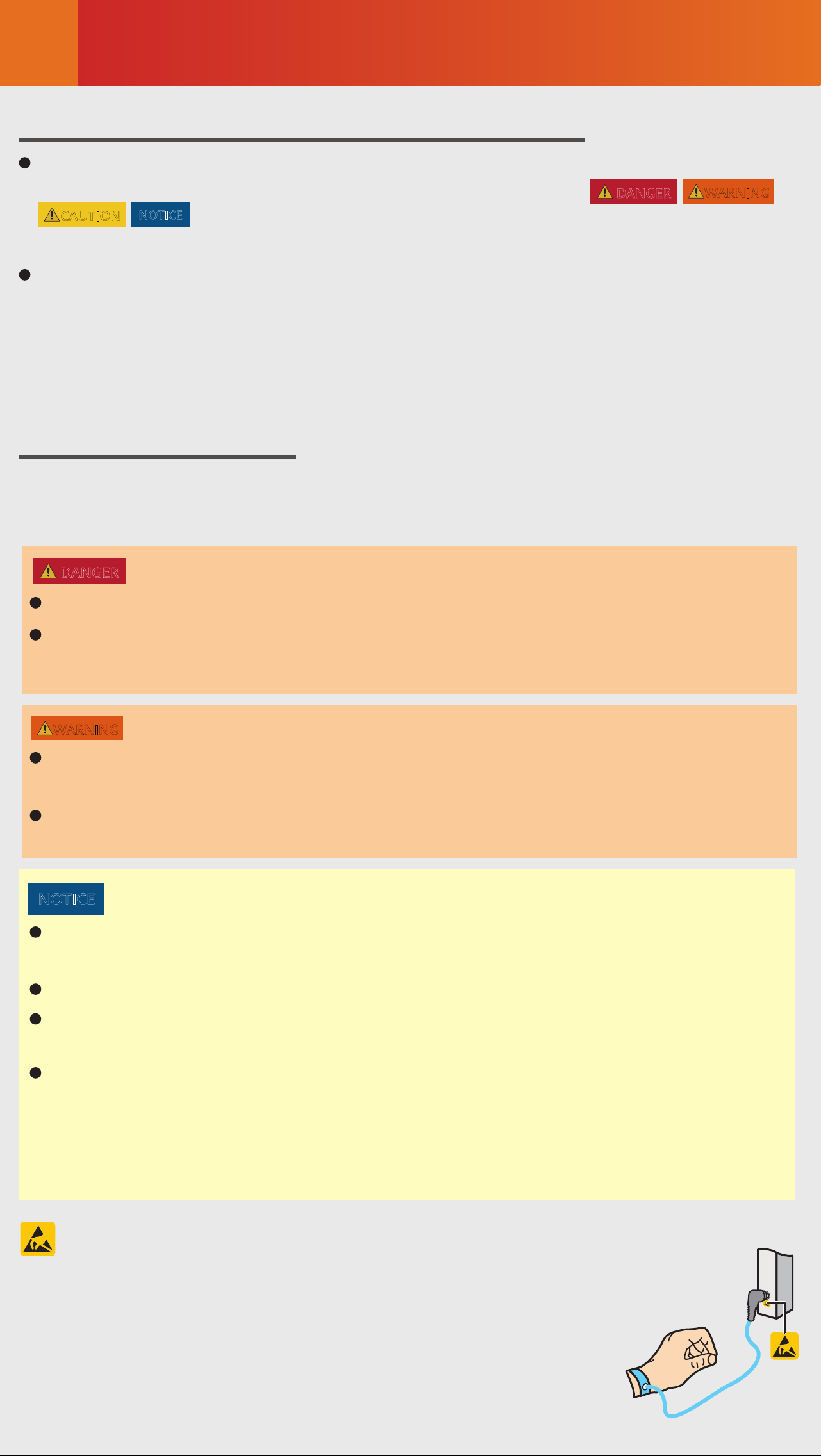
Before installing, operating, or maintaining the
equipment, wear an ESD wrist strap and insert the other
end into the ESD jack on the chassis or cabinet. Remove
conductive objects like jewelry and watches to prevent
damages to the equipment and cards caused by
electrostatic discharge.
ESD Protection
Site Requirements
3
precautions on the equipmentand in this document.
The device needs to be installed in a clean, dry, well ventilated, and
temperature-controllable standard equipment room. In addition, the
equipment room must be free from leaking or dripping water, heavy
dew, and condensing.
Dustproof measures must be taken in the installation site. This is
because dust will cause electrostatic discharges on the device and
aect connections of metal connectors and joints, shortening the
service life of the device and even resulting in device failures.
The installation site must be free from acidic, alkaline, and other
types of corrosive gases.
The device that is operating may cause radio interference. If this is the
case, relevant measures may be needed to reduce the interference.
Generally, devices such as wireless antennas should not be installed in
the equipment room. If such devices must be installed indoors, ensure
that the electromagnetic environment meets relevant requirements or
take necessary electromagnetic shielding measures.
The device to be installed must be used indoors. To ensure normal
operation and long service life of the device, the following requirements
must be met:
The temperature and humidity in the installation site must meet device
requirements described in the following table.
Long-term operating
temperature [°C]
Relative operating
humidity [RH]
DC: -40°C ~ 65°C
AC: –20°C to +55°C
≤ 4000 m (For the altitude in the range of 1800 m
to 4000 m, the operating temperature of the device
decreases by 1°C every time the altitude increases
by 220 m.)
Item Requirements
Storage temperature
[°C]
–40°C to +70°C
Relative storage
humidity [RH]
Long-term operating
altitude [m]
Storage altitude [m] < 5000 m
NetEngine 8000 M14/PTN 6900-2-M14/NE40E-X2-
M14:
Long-term: 5% to 85% RH, non-condensing
Short-term: 5% to 95% RH, non-condensing
NetEngine 8000 M14/PTN 6900-2-M14/NE40E-X2-
M14: 5% to 95% RH, non-condensing

Cabinet Requirements
4
Installing a Device
5
The device must be installed in an IEC 19-inch cabinet or an ETSI 21-inch
cabinet.
Huawei A63B cabinet is recommended. If customers choose to purchase
cabinets by themselves, the cabinets must meet the following require-
ments:
NOTE
1. 19-inch or 21-inch cabinet with a depth of greater than or equal to 300
mm.
2. The cabling space in front of the cabinet complies with the cabling
space requirements of boards. It is recommended that the distance
between the cabinet door and any device board be greater than or equal
to 120 mm. If the cabling space is insucient, cables will block the
cabinet door from closing. Therefore, a cabinet with broader cabling space
is recommended, such as a cabinet with a convex door.
3. The device draws air from the left side and exhausts from the right
side. Therefore, if the device is installed in a 19-inch cabinet, there must
be a clearance of at least 75 mm at the left and right sides of the cabinet
to ensure good ventilation.
4. The porosity of each cabinet door must be greater than 50%, meeting
heat dissipation requirements of devices.
5. The cabinet has installation accessories, such as guide rails, floating
nuts, and screws.
6. The cabinet has a ground terminal to connect to the device.
7. The cabinet has a cable outlet on the top or at the bottom for
overhead or underfloor cabling.
The cabinet may be installed on an ESD floor or a concrete floor. For de-
tails about how to install a cabinet, see the Cabinet Installation Guide
delivered with a cabinet.
When installing a device in a cabinet, ensure that the total heat
consumption of all devices in the cabinet does not exceed the heat
dissipation capability of the cabinet.
To prevent air return from aecting heat dissipation, leave at least 2 U
space between devices in the cabinet. In addition, if the cabinet has
middle columns, devices can be installed in stacking mode.
Do not block the heat dissipation holes on panels.
A device that needs to share the same cabinet with other devices cannot
be installed near the air exhaust vents of those devices.
Consider the impact of a device's air exhaust vent on adjacent devices to
prevent high temperature.
When fastening floating nuts, ensure that there is at least 75 mm space
on the left and right sides of the device for ventilation after device
installation.
CAUTION
Installing a Device
5
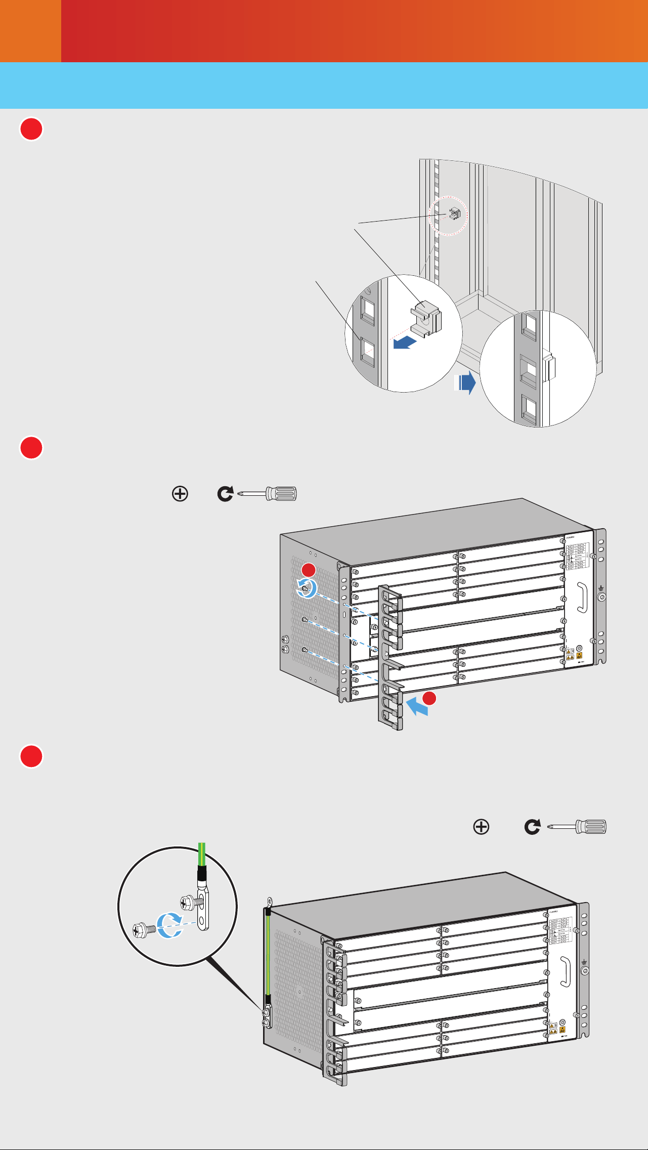
5.1 Installing a Device in an IEC 19-Inch Cabinet
1
Install floating nuts onto the cabinet.
2
Install the cable management frame onto the device.
3
Connect the PGND cable to the front or side face of the device.
The side face is preferred.
M3
2
1
M6
Installation hole
Floating nut
Installing a Device
5
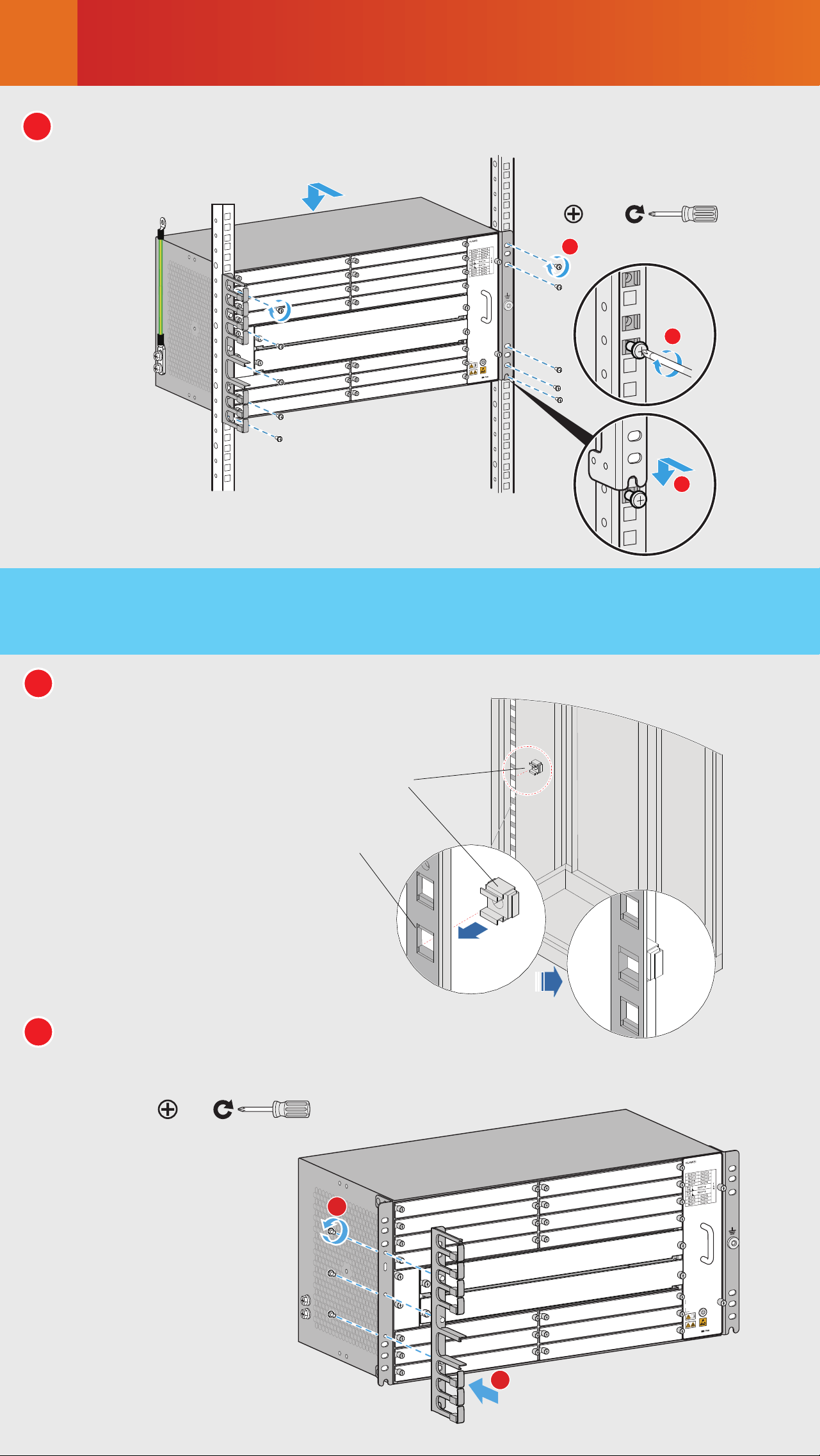
5.2 Installing a Device in an ETSI 21-Inch Cabinet
with Front Columns
2
Install the cable management frame
and power cable tray onto the device.
1
Install floating nuts onto the cabinet.
4
Install the device into the cabinet.
M6
1
2
3
2
1
M3
Installation hole
Floating nut
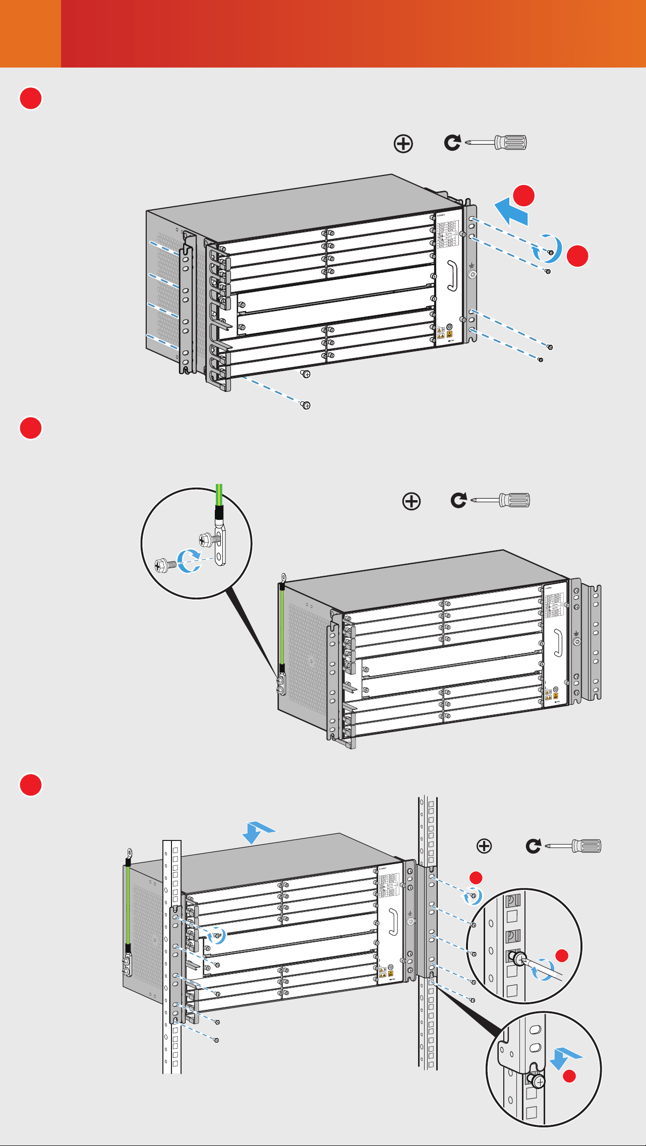
Installing a Device
5
5
Install the device into the cabinet.
4
Connect the PGND cable to the front or side face of the device.
The side face is preferred.
3
Install conversion mounting ears on both sides of the device.
M6
1
2
M6
2
M6
1
2
3
Installing a Device
5
5.3 Installing a Device in an ETSI 21-Inch Cabinet
with Middle Columns
1
Install floating nuts onto the cabinet.
2
Install the cable management frame
and power cable tray onto the device.
M3
2
1
M6
Installation hole
Floating nut
3
Remove the mounting ear on
the left side of the chassis,
move it to the middle of the
panel, and install an ETSI
conversion mounting ear.
Then, take out a 19-inch
mounting ear and an ETSI
conversion mounting ear
from the auxiliary material
package and install them on
the right side of the chassis
(that is, the side with a cable
management frame).
Installing a Device
5
4
IInstall the 19-inch mounting ears and conversion mounting ears
on the left and right sides of the device.
5
Connect the PGND cable to the
front or side face of the device.
The side face is preferred.
6
Install the device into the cabinet.
M4
2
1
M6
M6
Installing Components
6
6.1 Installing Boards
Installing an interface board
Installing a main control board
STAT
L/A0
L/A1
STAT
L/A0
L/A1
3
1
4
2
M3
L/A1
ACTC
ACTX
SYNG
PROG
STAT
L/A1
ACTC
ACTX
SYNG
PROG
STAT
L/A1
ACTC
ACTX
SYNG
PROG
STAT
3
1
4
2
M3
1
2
3
4
CAUTION
Hold the ejector levers on the panel with both hands, and turn them
outward until they make an angle of 45 degrees with the panel.
Push the board along guide rails into the slot until it cannot move
forward.
Lower the ejector levers and push them inward until they cannot
move forward. (When installing a main control board, ensure that
the latches of the ejector levers are locked into the panel.)
Use a Phillips screwdriver to fasten the captive screws clockwise on
both sides of the panel.
Wear ESD wrist straps or ESD gloves before installing or removing a board.
Filler panels must be installed in vacant slots to ensure good
electromagnetic compatibility and meet dust-proof and heat dissipation
requirements.
The filler panel in a slot can be removed only before you insert an interface
board into the slot. Removing multiple filler panels and then inserting
multiple interface boards at a time is not allowed.
When sliding a board into a slot along guide rails, press the front panel of
the board with your thumbs, and push the board until it cannot move
forward. Then, fasten the ejector levers.
Installing Components
6
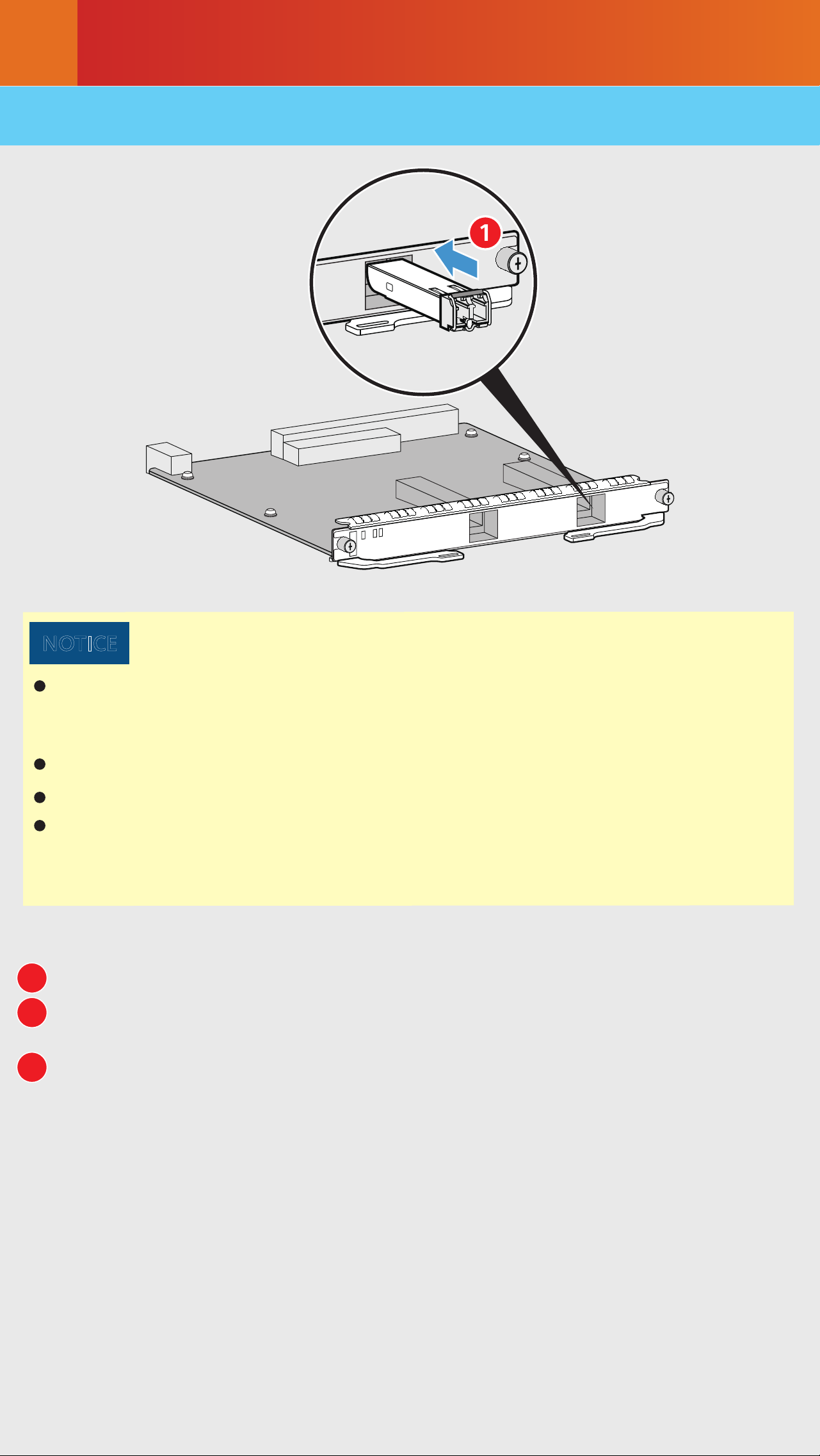
6.2 Installing Optical Modules
STAT
L/A0
L/A1
1
NOTICE
Huawei-certified optical modules need to be used. This is because the
reliability of non-Huawei-certified optical modules cannot be ensured,
and using such modules may aect service stability.
Wear ESD wrist straps or ESD gloves before installing optical modules.
Install dust-proof caps on optical ports without optical modules.
Ensure that optical modules are not reversely installed. If an optical
module cannot be completely inserted into an optical port, do not force
it into the port. Turn the optical module over and try again.
1
2
3
Insert the optical module fully into the optical port.
Connect optical fibers according to the required connection
sequence.
Check the LINK indicator on the corresponding optical port. If the
LINK indicator is steady green, the optical module is working
properly.
Connecting Cables
7
Cable layout for a DC device
Cable layout for an AC device
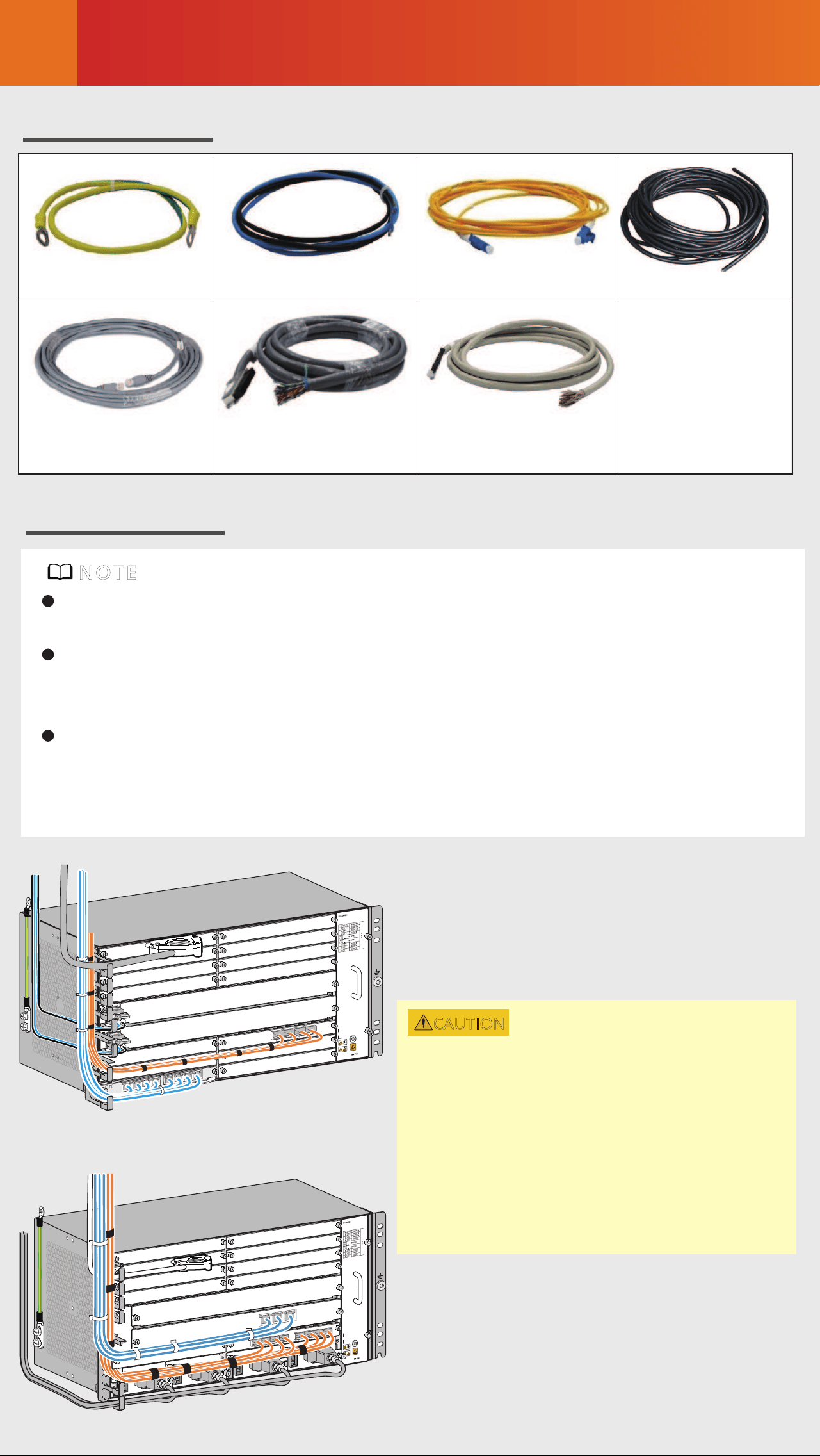
Common Cables
PUSH
PUSH
STAT
SRV
AUXQ
PGND cable Optical fiberDC power cable AC power cable
Shielded Ethernet
cable
120-ohm 16 x E1
cable
75-ohm 16 x E1
cable
Routing Planning
If cables are routed on the rear of a device, ensure that the cables do not
block the air vents of the device to achieve proper heat dissipation.
Before routing cables, make temporary labels and attach them to the
cables. After the cables are routed, make formal labels and attach them
to the cables as required.
Do not bundle or route outdoor cables (such as outdoor antenna feeders
and outdoor power cables) and indoor cables together in the cabinet or
cable tray.
NOTE
CAUTION
It is recommended that the power
cables, E1 cables, optical fibers, and
Ethernet cables of an AC or DC device
be routed on the left side of the
cabinet. To facilitate power module
maintenance, keep the cables away
from the upper or lower power
module insertion and removal areas.
Connecting Cables
7
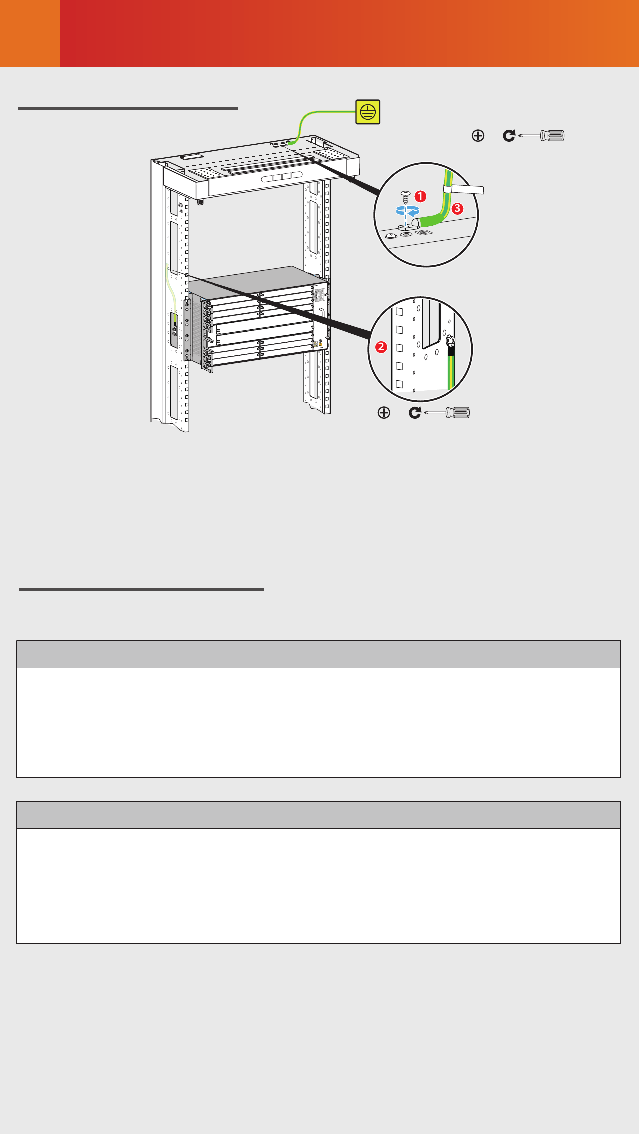
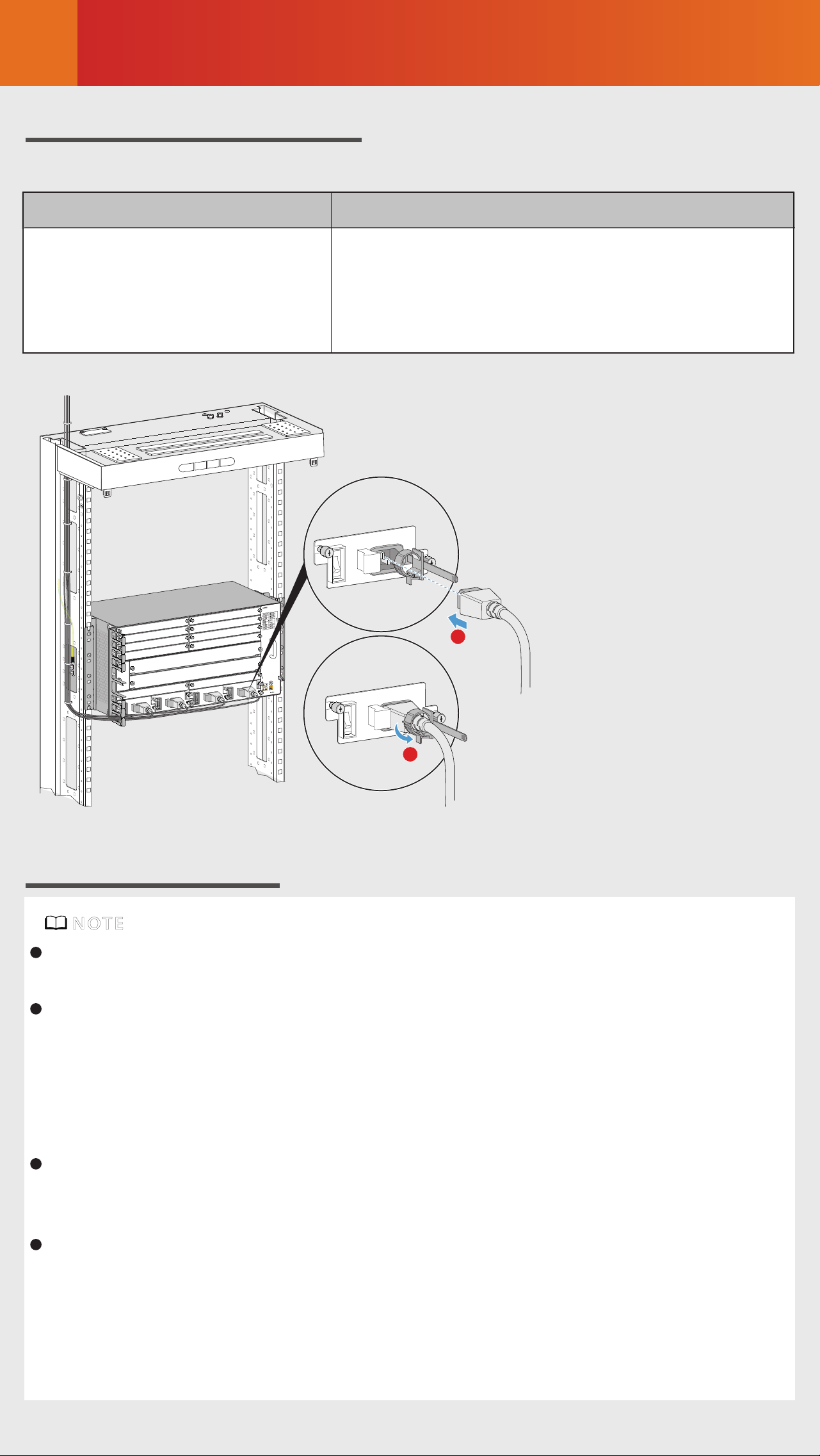
Installing a PGND Cable
TO:
X-XXX-X-X
M8
1
3
2
M6
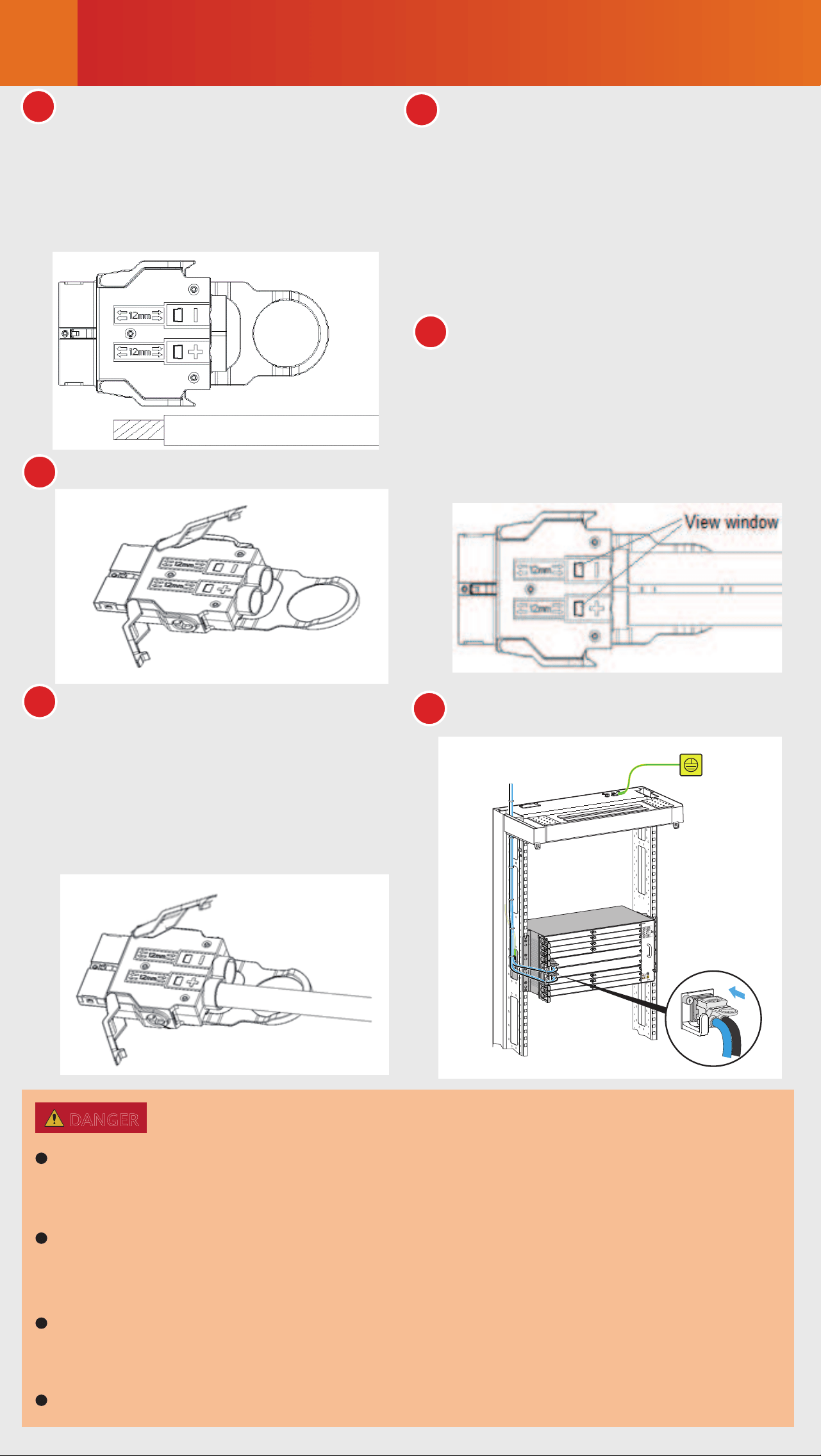
Installing DC Power Cables
Check the fuse capacity of the external power supply.
Device Model Recommended Fuse Capacity
NetEngine 8000 M14
PTN 6900-2-M14
NE40E-X2-M14
Device Model
NetEngine 8000 M14
PTN 6900-2-M14
NE40E-X2-M14
Maximum Cable Size
≥63A, ≤80A
(Select 10 mm² cables for 63 A circuit breakers,
and 16 mm² cables for circuit breakers
higher than 63 A.)
16mm², 10mm² (0-14meters) recommended,
16mm² (15-23meters) recommended
Connecting Cables
7
3
4
5
6
Insert the connector into the PIU.
PUSH
PUSH
PUSH
Insert one power cable into the
corresponding hole according to
its pole (positive or negative).
Then, fasten the screws and
latch. The method of power
cable installation for the other
pole is similar.
Drag each power cable slightly
to check whether it is fastened.
If the cable is loose or its core
wires are exposed, disconnect
the cable, cut o the split part,
re-strip the cable, and then
reconnect it.
Check whether the cables have
been properly connected and
whether the cable sheath has
been pressed through view
windows. If not, repeat the
preceding steps to prepare and
connect the cables again.
The conductor of each power cable must be completely inserted into
the DC connector to prevent electric shocks. Shut down the power
supply before connecting or disconnecting power cables.
The power cables must be correctly connected according to the
labels on the PIU. If the power cables are reversely connected, the
device cannot be powered on.
Ensure that the power cables do not have joints or excess part, and
are not coiled. The bent part of the cables must have enough slack,
with a bending radius of no less than 20 mm.
No bare copper wire is allowed at power cable terminals.
DANGER
1
2
Take out the power connector
from the packaging bag, and
then strip each DC power cable
for a length of 6 mm to 10 mm
according to the mark on the
silkscreen of the connector.
Unfasten the connector latch.
Connecting Cables
7
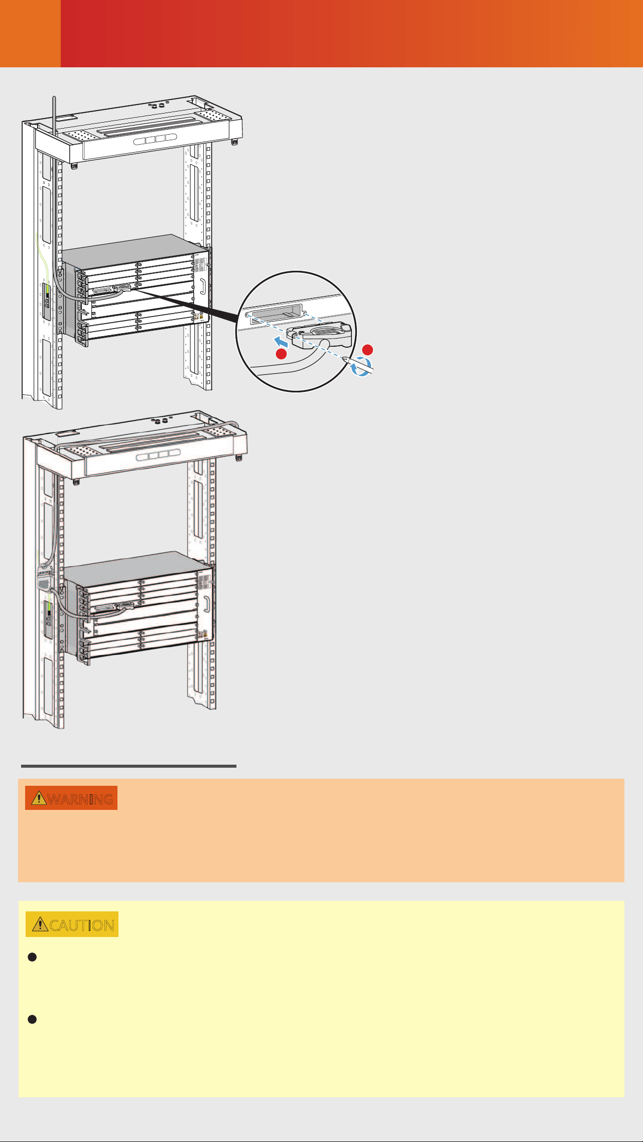
Installing an E1 Cable
To avoid aecting right-hand board maintenance after cable routing, you
are advised to connect an E1 cable only to a left-hand board.
An E1 cable is a thin cable with a diameter of 1.6 mm. It needs to be con-
nected to a DDF using an MC 75-1-1 connector and a crimping tool with
a bore diameter of 1.7 mm. If you use an MC 75-1-1 connector and a
crimping tool with a bore diameter of 2.5 mm, crimp the joint twice. Spe-
cifically, after performing the first crimping, rotate the coaxial connector
by 90 degrees and crimp the joint again.
An E1 cable with a negative 45-degree connector is delivered by default.
If you use this cable, connect the connector to the desired board port and
use a Phillips screwdriver to fasten screws.
If you use an E1 cable with a positive 45-degree connector, the cable must
be routed without aecting fan module installation or removal. To
achieve this, you need to use an E1 transfer cable instead of directly con-
necting the connector to a board port. Specifically, connect the cable to
the E1 transfer cable, and then connect the E1 transfer cable to the de-
sired board port.
NOTE
Installing an AC Power Cable
Check the fuse capacity of the external power supply.
Device Model Recommended Fuse Capacity
NetEngine 8000 M14
PTN 6900-2-M14
NE40E-X2-M14
2
1
≥10A, ≤16A
For hierarchical power supplying protection,
the current of the circuit breaker at the
user side should be 10 A.
Connecting Cables
7
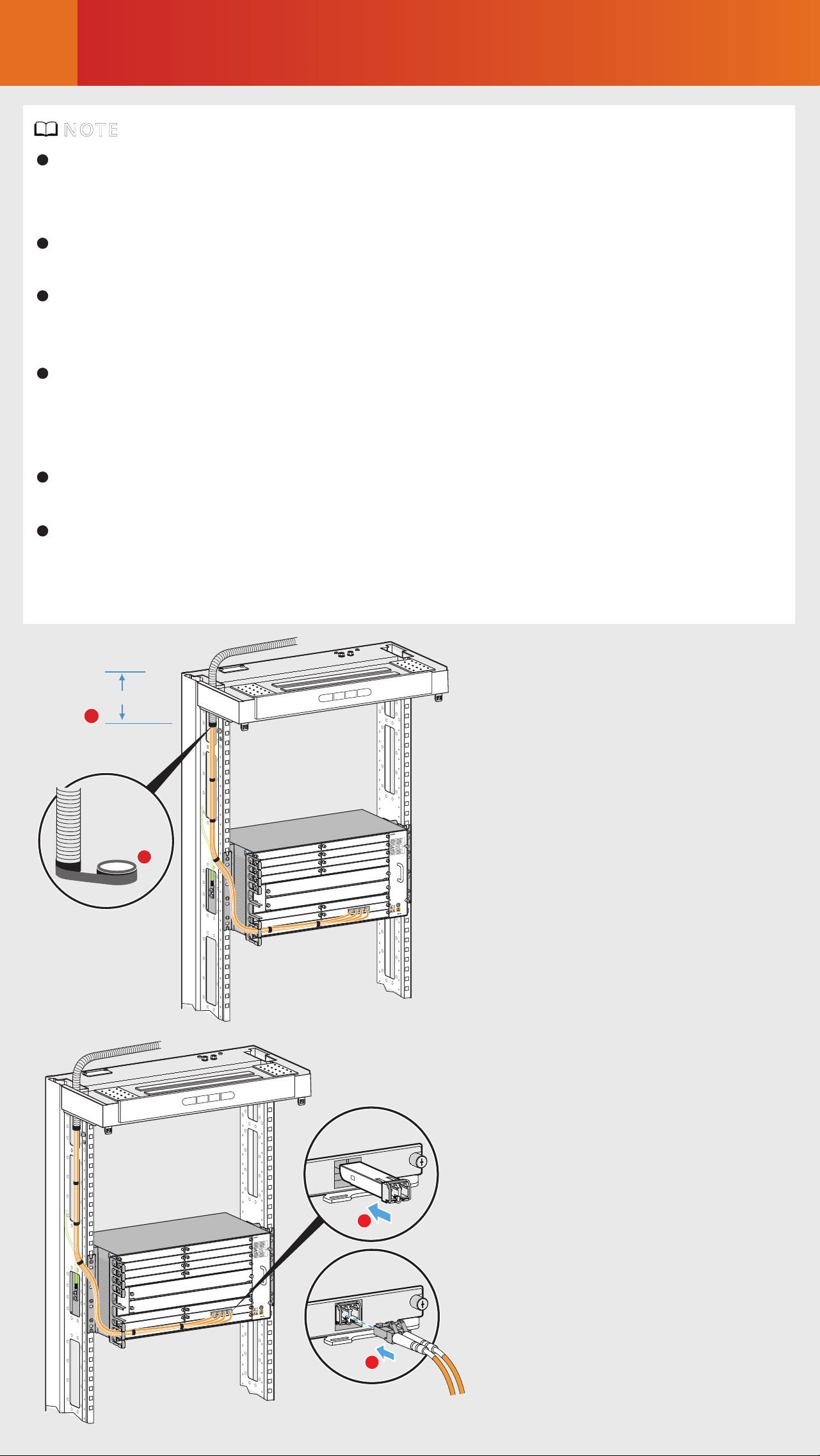
Installing Optical Fibers
STAT
L/A0
2
1
Installing an E1 cable with
a negative 45-degree connector
Installing an E1 cable with
a positive 45-degree connector
When performing operations such as installing or maintaining optical
fibers, do not move your eyes close to or look into the optical fiber
outlet without eye protection.
WARNING
CAUTION
Before routing internal optical fibers, install fixed optical attenua-
tors at the corresponding optical ports on boards according to the
fixed optical attenuator installation table.
If you use the recommended A63B cabinet, it is recommended that
only one optical attenuator be added. If multiple optical attenua-
tors are added, there is a risk that the cabinet door cannot be prop-
erly opened.
Connecting Cables
7
1
100mm (3.94 in.)
2
1
2
Handling Corrugated Pipes
Installing Optical Fibers
The bending radius of a single-mode G.657A2 optical fiber is no less
than 10 mm, and that of a multi-mode A1b optical fiber is no less than
30 mm.
After laying out optical fibers, use binding straps to bind the fibers
neatly without squeezing them.
After the optical fibers are connected, the optical ports and optical con-
nectors that are not used must be covered by dustproof plugs and dust-
proof caps, respectively.
Do not use an open-end corrugated pipe to hold excessive optical fibers.
It is recommended that an open-end corrugated pipe with a diameter of
32 mm accommodate a maximum of 60 fibers with a diameter of 2
mm.
It is recommended that the length of a corrugated pipe inside a cabinet
be about 10 cm.
Use an A63B cabinet as an example. If corrugated pipes need to be used
in the cabling area on the top of the cabinet, a maximum of two such
pipes are supported, accommodating a maximum of 120 optical fibers.
If more optical fibers are required, use the E1 cable hole.
NOTE
Connecting Cables
7
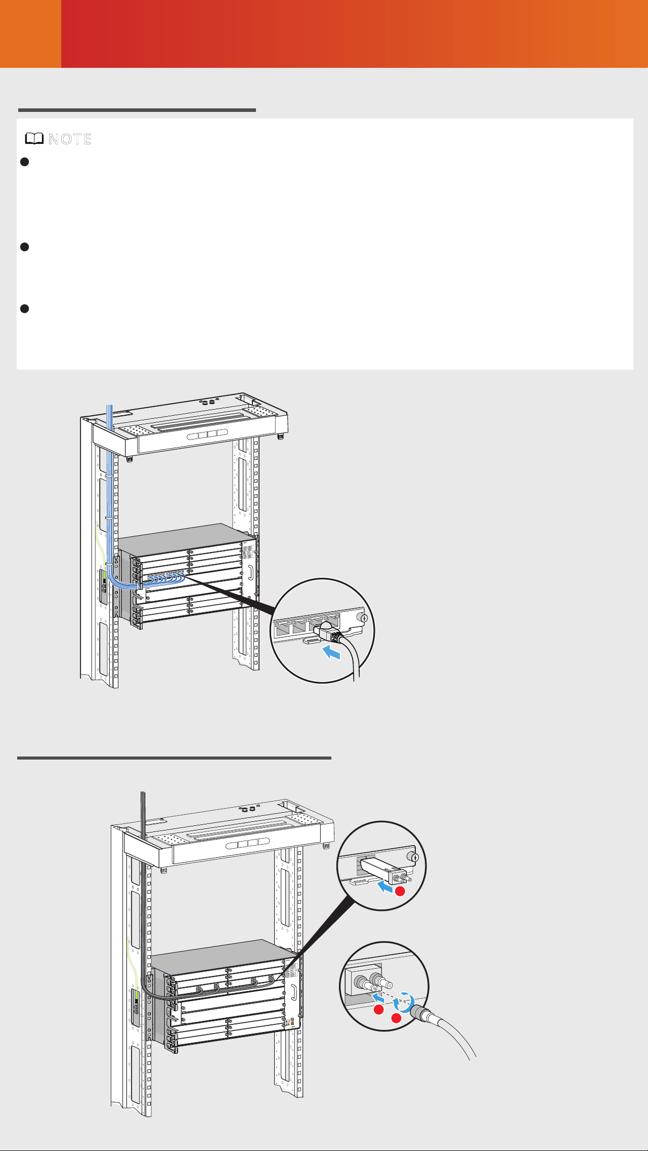
Installing Ethernet Cables
Installing a 75-ohm Coaxial Cable
FE1
FE2
FE3
FE4
2
3
1
The maximum number of shielded Ethernet cables supported by a flat-door
cabinet is limited. For example, a 300 mm deep flat-door N63B/N63E cabi-
net supports a maximum of six shielded Ethernet cables per layer of inter-
face boards.
In contrast, a convex-door cabinet supports more shielded Ethernet cables.
For example, a convex-door A63B/A63E cabinet supports a maximum of 16
shielded Ethernet cables per layer of interface boards.
Connecting a device to an NMS server requires two Ethernet cables: one for
the active main control board and the other for the standby main control
board.
NOTE
Checking the Installation
8
Check Before Power-on
If the power supply voltage does not meet requirements, do not power on
the device.
Check whether fixed optical attenuators have been added in accordance
with corresponding configuration rules.
Check whether the fuse capacity of the external power supply meets re-
quirements.
Check whether the external power supply voltage is normal.
CAUTION
STAT
Indicator Abnormal State Possible Cause Handling Procedure
Steady red
Steady o
Signals on an
optical port are
lost.
The corre-
sponding
module cannot
be detected.
1. Power on the peer chassis.
2. Check the peer board and
ensure that the transmit opti-
cal power of the board is
normal.
3. Check that fiber connections
are correct.
4. If there is no fixed optical
attenuator at the optical port,
check the fiber attenuation,
clean the fiber connector, and
replace damaged fibers until
the indicator turns green.
If the chassis is powered on
but all the indicators on the
board are o, contact software
commissioning engineers to
replace the board.
Before performing a power-on check,
turn o all the switches on the device
and external power supply system.
WARNING
The following table describes the
states of indicators when the device
is operating properly.
Hardware Module
Steady greenPower module
Steady green
Steady green
Steady green
Steady green
Steady green
Fan module
Main control board
Interface board
PWR
FAN
STAT
PROG
STAT
L/A
Indicator State
Power-on Check
If board indicators are in speci-
fied abnormal states after you
power on the device, handle
the abnormalities onsite.
For more information about device indi-
cators, see in the
corresponding product documentation.
NOTE
HardwareDescription

Obtaining Product Documentation
and Technical Support
9
Log in to Huawei enterprise technical support website
(https://support.huawei.com/enterprise) and select a specific product
model and version to find its documentation.
Log in to Huawei enterprise support community
(
https://forum.huawei.com/enterprise), and post your questions in the
community.
Log in to Huawei carrier technical support website
(
https://support.huawei.com/carrier), and select a specific product
model and version to find its documentation.
Log in to carrier enterprise support community
(
https://forum.huawei.com/carrier) and post your questions in the
community.
For enterprise users:
For carrier usesrs:
Huawei Carrier Technical Support
Huawei Enterprise Technical Support
Trademarks and Permissions
All other trademarks and trade names mentioned in this document are
the property of their respective holders.
Copyright © Huawei Technologies Co., Ltd. 2021. All rights reserved.
No part of this document may be reproduced or transmitted in any form
or by any means without prior written consent of Huawei Technologies
Co., Ltd.
and other Huawei trademarks are trademarks of Huawei
Technologies Co., Ltd.

Appendix Inspecting and Cleaning
Optical Fiber Connectors and Adapters
Since the 50G optical module link uses the PAM4 encoding tech-
nology, there are higher requirements on the optical fiber and
cable quality and the link is more sensitive to multipath reflection
interference of signals. If the fiber link connector, fiber section, or
fiber splicing surface is dirty, optical signals are reflected back
and forth on the fiber link, causing interference due to co-chan-
nel noise on the receive side. As a result, the optical link is unsta-
ble or intermittently disconnected. To prevent this issue, you need
to check and clean the optical fiber connectors before installa-
tion. For details, see Installation and maintenance > Preparing for
the installation> Inspecting and Cleaning Optical Fiber Connec-
tors and Adapters in the product documentation.